Gov fema fema356
519
FEMA 356 Prestandard November 2000 The ASCE/FEMA 273 Prestandard Project has been completed. This joint effort between ASCE and FEMA has taken the first step in updating and converting the FEMA 273 — NEHRP Guidelines for the Seismic Rehabilitation of Buildings in to a national consensus standard. In the process, recent research and technical advancements have been incorporated into the provisions when deemed appropriate by the Project Team and approved by the ASCE Standards Committee on Seismic Rehabilitation. The resulting document, FEMA 356— Prestandard and Commentary for the Seismic Rehabilitation of Buildings, is now available for use. Users of this Prestandard need to be aware that the ASCE Standards Committee on Seismic Rehabilitation of Buildings is currently reviewing, discussing, and potentially revising the document prior to its being issued as a voluntary consensus standard. The Standards Committee, with over 150 members, has voted to accept this Prestandard as the initial draft for their standard which, upon its completion, will be suitable for adoption by building codes and inclusion in contracts. In early 2001, the Standards Committee will begin committee balloting on this document to be followed by an open Public Ballot period. The process that the Standards Committee will follow will be in accordance with the ASCE Rules for Standards Committees. These Rules have been approved by the ASCE Board of Direction and by the American National Standards Institute (ANSI). A copy of these Rules may be found in the ASCE Official Register.
-
Upload
independent -
Category
Documents
-
view
0 -
download
0
Transcript of Gov fema fema356
FEMA 356 Prestandard
November 2000
The ASCE/FEMA 273 Prestandard Project has been completed. This joint effort between ASCE and FEMA has taken the first step in updating and converting the FEMA 273 — NEHRP Guidelines for the Seismic Rehabilitation of Buildings in to a national consensus standard. In the process, recent research and technical advancements have been incorporated into the provisions when deemed appropriate by the Project Team and approved by the ASCE Standards Committee on Seismic Rehabilitation. The resulting document, FEMA 356— Prestandard and Commentary for the Seismic Rehabilitation of Buildings, is now available for use. Users of this Prestandard need to be aware that the ASCE Standards Committee on Seismic Rehabilitation of Buildings is currently reviewing, discussing, and potentially revising the document prior to its being issued as a voluntary consensus standard. The Standards Committee, with over 150 members, has voted to accept this Prestandard as the initial draft for their standard which, upon its completion, will be suitable for adoption by building codes and inclusion in contracts. In early 2001, the Standards Committee will begin committee balloting on this document to be followed by an open Public Ballot period. The process that the Standards Committee will follow will be in accordance with the ASCE Rules for Standards Committees. These Rules have been approved by the ASCE Board of Direction and by the American National Standards Institute (ANSI). A copy of these Rules may be found in the ASCE Official Register.

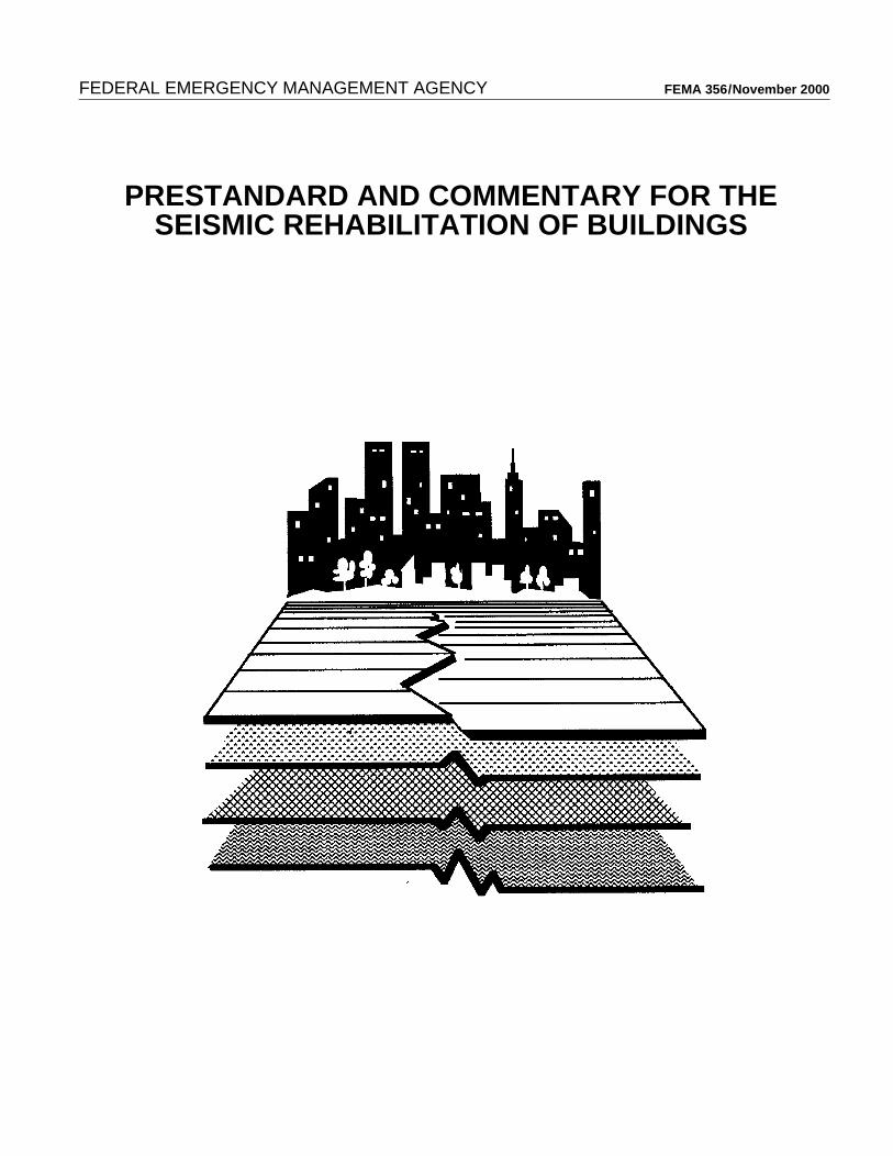
FEDERAL EMERGENCY MANAGEMENT AGENCY FEMA 356 / November 2000
PRESTANDARD AND COMMENTARY FOR THESEISMIC REHABILITATION OF BUILDINGS

FEDERAL EMERGENCY MANAGEMENT AGENCY FEMA 356 / November 2000
PRESTANDARD AND COMMENTARY FOR THESEISMIC REHABILITATION OF BUILDINGS

NOTICE: This report was prepared under a cooperative agreement between the Federal Emergency Management Agency and the American Society of Civil Engineers.
Any opinions, findings, conclusions, or recommendations expressed in this publication do not necessarily reflect the views of the Federal Emergency Management Agency (FEMA) or the American Society of Civil Engineers (ASCE). Additionally, neither FEMA, ASCE, nor any of their employees make any warranty, expressed or implied, nor assumes any legal liability or responsibility for the accuracy, completeness, or usefulness of any information, prod-uct, or process included in this publication. Users of information from this publication assume all liability arising from such use.
For further information concerning this document or the activities of the ASCE, contact the American Society of Civil Engineers, 1801 Alexander Bell Drive, Reston, Virginia, 20191, (703) 295-6000.
FEDERAL EMERGENCY MANAGEMENT AGENCY FEMA 356 / November 2000
PRESTANDARD AND COMMENTARY FOR THESEISMIC REHABILITATION OF BUILDINGS
Prepared byAMERICAN SOCIETY OF CIVIL ENGINEERS
Reston, Virginia
Prepared forFEDERAL EMERGENCY MANAGEMENT AGENCY
Washington, D.C.
November 2000Federal Emergency Management Agency
Washington, D.C.

ASCE Standards Program and the Structural Engineering InstituteThe Structural Engineering Institute (SEI) of the American Society of Civil Engineers (ASCE) was created in 1996 as a semi-autonomous organization within ASCE to focus on serving the needs of the broad structural engineering community. The mis-sion of SEI is to advance the profession of structural engineering by enhancing and sharing knowledge, supporting research, and improving business and professional practices. SEI is comprised of three divisions: Technical Activities, Business and Profes-sional Activities, and Codes and Standards Activities.
The standards activities of SEI operate under the umbrella of ASCE’s standards program. ASCE has over 125,000 members worldwide. More than 7,000 of these members participate on over 500 technical committees, 44 of which are active Standards Committees that have resulted in over 30 published standards, to date. In addition to individual participation, ASCE's standards program actively encourages participation by representatives of affected organizations, thereby expanding the input into the stan-dards developing process well beyond ASCE’s 125,000 members to ensure a high level of exposure and participation.
ASCE’s standards program, and hence SEI’s activities, are governed by the Rules for Standards Committees (referred to herein as ASCE Rules). These Rules are reviewed and approved by the American National Standards Institute (ANSI), which accredits ASCE as a standards developing organization (SDO). Membership and participation in ASCE's standards program is open to both members and non-members of ASCE. Standards committees are required to publicize their activities through ASCE News and to distribute meeting agendas at least 30 days in advance, to afford all interested parties the opportunity to participate. To fur-ther extend beyond its membership, ASCE distributes press releases on new standards activities, and to announce when a stan-dard progresses into the public ballot phase. ASCE’s Public Relations Department maintains a list of over 400 civil engineering related publications, and it is common for 40 to 50 press releases to be distributed, thereby notifying and soliciting comments from several hundred thousand individuals.
An ASCE standards committee must have a minimum of 12 members, though, current committees range in size from 12 to over 200 members. To join a standards committee, an application must be completed which describes the individual’s qualifications and interest in the respective subject. However, acceptance of an applicant is not based solely on technical qualifications. During the initial formation of a standards committee, membership is open to any interested party, provided they can demonstrate that they are directly or indirectly affected by the activity.
As the committee begins its work to bring the standard into suitable condition for balloting, the committee also must ensure that its membership is “balanced.” ASCE Rules define a balanced committee and require that members be classified into one of three categories: Producer, Consumer, or General Interest. For standards of regulatory interest, a subclass of General Interest is estab-lished for Regulators. Each of the three categories must compose from 20 to 40 percent of the total committee membership. When the subclass of Regulators is established, they must compose 5 to 15 percent of the total membership.
Producers include representatives of manufacturers, distributors, developers, contractors and subcontractors, construction labor organizations, associations of these groups, and professional consultants to these groups. Consumers include representatives of owners, owner's organizations, designers, consultants retained by owners, testing laboratories retained by owners, and insurance companies serving owners. General Interest members include researchers from private, state and federal organizations, represen-tatives of public interest groups, representatives of consumer organizations, and representatives of standards and model code organizations. Regulators include representatives of regulatory organizations at local, state, or federal levels of government.
Recognizing that committee members are volunteers whose time and travel budgets are limited, ASCE's Rules are designed to allow members to fully participate in the work of the standards committee without attending committee meetings. Responding in writing to letter ballots is a proven and effective means of participation.
ASCE’s ANSI accreditation ensures that all standards developed for the civil engineering profession that are intended to become part of the laws which govern the profession have been developed through a process that is fully open, allows for the participa-tion of all interested parties, and provides participants with due process. Standards resulting from this ANSI process are true national voluntary consensus standards which serve and benefit the general public.

Participants
Project ManagersUgo Morelli, FEMA Project OfficerThomas R. McLane, ASCE Project Manager
Project TeamChris D. Poland, Principal InvestigatorJon A. Heintz, AuthorAshvin Shah, AuthorVicky Vance May, AuthorMelvyn GreenRonald O. HamburgerWilliam T. HolmesJack P. MoehleMike MehrainLawrence D. ReaveleyChristopher RojahnJim RossbergDaniel ShapiroDiana Todd
Project Advisory CommitteeJohn R. Baals, ChairJames CagleyEdwin T. DeanS.K. GhoshJames O. JirsaPatrick J. LamaMichael ValleyRichard A. VognildEugene Zeller
Special Study ParticipantsDaniel P. AbramsJohn M. CoilCraig D. ComartinW. Paul GrantDarrick B. HomJohn HooperBrian KehoePeter Somers
Desktop PublishingKris Ingle
FEMA 356 Seismic Rehabilitation Prestandard v

vi Seismic Rehabilitation Prestandard FEMA 356

Foreword
The preparation of this prestandard was originally undertaken with two principal and complementary objectives. The first was to encourage the wider application of the NEHRP Guidelines for the Seismic Rehabilitation of Buildings, FEMA 273, by converting it into mandatory language. Design professionals and building officials thus would have at their disposal a more specific reference document for making buildings more resistant to earthquakes. This volume fully meets this first objective.
The second objective was to provide a basis for a nationally recognized, ANSI-approved standard that would further help in disseminating and incorporating the approaches and technology of the prestandard into the mainstream of design and construction practices in the United States. How successfully this volume achieves the second objective will become apparent with the passage of time, as this prestandard goes through the balloting process of the American Society of Civil Engineers.
Several additional related efforts were ongoing during the development of this prestandard. A concerted effort was made to gather any new information produced by these endeavors. Topics varied considerably, but typically covered approaches, methodologies, and criteria. Whenever an analysis of the new information disclosed significant advances or improvements in the state-of-the-practice, they were included in this volume. Thus, maintaining FEMA 273 as a living document—a process to which FEMA is strongly committed—is continuing.
FEMA and the Project Officer are deeply thankful to the members of the Project Team and consultants, the Project Advisory Committee, and the staff of the American Society of Civil Engineers for their dedicated efforts in completing this prestandard, which is a significant addition to the bibliography on seismic safety of existing buildings.
The Federal Emergency Management Agency
FEMA 356 Seismic Rehabilitation Prestandard vii

viii Seismic Rehabilitation Prestandard FEMA 356
Preface
The title of this document, FEMA 356 Prestandard and Commentary for the Seismic Rehabilitation of Buildings, incorporates a word that not all users may be familiar with. That word—prestandard—has a special meaning within the ASCE Standards Program in that it signifies the document has been accepted for use as the start of the formal standard development process, however, the document has yet to be fully processed as a voluntary consensus standard.
Users of this prestandard should be aware that the ASCE Standards Committee on Seismic Rehabilitation of Buildings is currently reviewing, discussing, and potentially revising the document prior to issuing it as a voluntary consensus standard. The Standards Committee, with over 150 members, has voted to accept this prestandard as the initial draft for their standard which, upon completion, will be suitable for adoption by building codes and inclusion in contracts. In early
2001, the Standards Committee will begin committee balloting on this document to be followed by an open public ballot period. The process the Standards Committee will follow will be in accordance with the ASCE Rules for Standards Committees. These rules have been approved by the ASCE Board of Direction and by the American National Standards Institute (ANSI). A copy of these rules may be found in the ASCE Official Register.
If you would like to participate in the formal standard development process either as a member of the Standards Committee or as part of the public ballot process, please contact ASCE's Standards Coordinator, Kim Brubaker, ASCE, 1801 Alexander Bell Drive, Reston, VA 20191.
American Society of Civil Engineers
FEMA 356 Seismic Rehabilitation Prestandard ix

x Seismic Rehabilitation Prestandard FEMA 356

Table of Contents
Foreword . . . . . . . . . . . . . . . . . . . . . . . . . . . . . . . . . . . . . . . . . . . . . . . . . . . . . . . . . . . . . . . . . . . . . . . . . . . . . ix
Preface . . . . . . . . . . . . . . . . . . . . . . . . . . . . . . . . . . . . . . . . . . . . . . . . . . . . . . . . . . . . . . . . . . . . . . . . . . . . . . . xi
1. Rehabilitation Requirements . . . . . . . . . . . . . . . . . . . . . . . . . . . . . . . . . . . . . . . . . . . . . . . . . . . . . . 1-1
1.1 Scope . . . . . . . . . . . . . . . . . . . . . . . . . . . . . . . . . . . . . . . . . . . . . . . . . . . . . . . . . . . . . . . . . . . 1-11.2 Design Basis . . . . . . . . . . . . . . . . . . . . . . . . . . . . . . . . . . . . . . . . . . . . . . . . . . . . . . . . . . . . . 1-21.3 Seismic Rehabilitation Process . . . . . . . . . . . . . . . . . . . . . . . . . . . . . . . . . . . . . . . . . . . . . . . 1-4
1.3.1 Review Initial Considerations . . . . . . . . . . . . . . . . . . . . . . . . . . . . . . . . . . . . . . . . 1-61.3.2 Select Rehabilitation Objective . . . . . . . . . . . . . . . . . . . . . . . . . . . . . . . . . . . . . . . 1-71.3.3 Obtain As-Built Information . . . . . . . . . . . . . . . . . . . . . . . . . . . . . . . . . . . . . . . . . 1-71.3.4 Select Rehabilitation Method . . . . . . . . . . . . . . . . . . . . . . . . . . . . . . . . . . . . . . . . 1-71.3.5 Perform Rehabilitation Design . . . . . . . . . . . . . . . . . . . . . . . . . . . . . . . . . . . . . . . 1-71.3.6 Verify Rehabilitation Design . . . . . . . . . . . . . . . . . . . . . . . . . . . . . . . . . . . . . . . . 1-7
1.4 Rehabilitation Objectives . . . . . . . . . . . . . . . . . . . . . . . . . . . . . . . . . . . . . . . . . . . . . . . . . . . 1-81.4.1 Basic Safety Objective . . . . . . . . . . . . . . . . . . . . . . . . . . . . . . . . . . . . . . . . . . . . . 1-91.4.2 Enhanced Rehabilitation Objectives . . . . . . . . . . . . . . . . . . . . . . . . . . . . . . . . . . . 1-91.4.3 Limited Rehabilitation Objectives . . . . . . . . . . . . . . . . . . . . . . . . . . . . . . . . . . . 1-10
1.5 Target Building Performance Levels . . . . . . . . . . . . . . . . . . . . . . . . . . . . . . . . . . . . . . . . . . 1-101.5.1 Structural Performance Levels and Ranges . . . . . . . . . . . . . . . . . . . . . . . . . . . . 1-111.5.2 Nonstructural Performance Levels . . . . . . . . . . . . . . . . . . . . . . . . . . . . . . . . . . . 1-171.5.3 Designation of Target Building Performance Levels . . . . . . . . . . . . . . . . . . . . . 1-23
1.6 Seismic Hazard . . . . . . . . . . . . . . . . . . . . . . . . . . . . . . . . . . . . . . . . . . . . . . . . . . . . . . . . . . 1-261.6.1 General Procedure for Hazard Due to Ground Shaking . . . . . . . . . . . . . . . . . . . 1-271.6.2 Site-Specific Procedure for Hazard Due to Ground Shaking . . . . . . . . . . . . . . 1-341.6.3 Zones of Seismicity . . . . . . . . . . . . . . . . . . . . . . . . . . . . . . . . . . . . . . . . . . . . . . . 1-35
2. General Requirements . . . . . . . . . . . . . . . . . . . . . . . . . . . . . . . . . . . . . . . . . . . . . . . . . . . . . . . . . . . 2-1
2.1 Scope . . . . . . . . . . . . . . . . . . . . . . . . . . . . . . . . . . . . . . . . . . . . . . . . . . . . . . . . . . . . . . . . . . . 2-12.2 As-Built Information . . . . . . . . . . . . . . . . . . . . . . . . . . . . . . . . . . . . . . . . . . . . . . . . . . . . . . . 2-1
2.2.1 Building Configuration . . . . . . . . . . . . . . . . . . . . . . . . . . . . . . . . . . . . . . . . . . . . . 2-22.2.2 Component Properties . . . . . . . . . . . . . . . . . . . . . . . . . . . . . . . . . . . . . . . . . . . . . . 2-22.2.3 Site Characterization and Geotechnical Information . . . . . . . . . . . . . . . . . . . . . . 2-22.2.4 Adjacent Buildings . . . . . . . . . . . . . . . . . . . . . . . . . . . . . . . . . . . . . . . . . . . . . . . . 2-32.2.5 Primary and Secondary Elements and Components . . . . . . . . . . . . . . . . . . . . . . . 2-42.2.6 Data Collection Requirements . . . . . . . . . . . . . . . . . . . . . . . . . . . . . . . . . . . . . . . 2-4
2.3 Rehabilitation Methods . . . . . . . . . . . . . . . . . . . . . . . . . . . . . . . . . . . . . . . . . . . . . . . . . . . . . 2-62.3.1 Simplified Rehabilitation Method . . . . . . . . . . . . . . . . . . . . . . . . . . . . . . . . . . . . . 2-62.3.2 Systematic Rehabilitation Method . . . . . . . . . . . . . . . . . . . . . . . . . . . . . . . . . . . . 2-7
2.4 Analysis Procedures . . . . . . . . . . . . . . . . . . . . . . . . . . . . . . . . . . . . . . . . . . . . . . . . . . . . . . . 2-82.4.1 Linear Procedures . . . . . . . . . . . . . . . . . . . . . . . . . . . . . . . . . . . . . . . . . . . . . . . . . 2-92.4.2 Nonlinear Procedures . . . . . . . . . . . . . . . . . . . . . . . . . . . . . . . . . . . . . . . . . . . . . 2-112.4.3 Alternative Rational Analysis . . . . . . . . . . . . . . . . . . . . . . . . . . . . . . . . . . . . . . . 2-122.4.4 Acceptance Criteria . . . . . . . . . . . . . . . . . . . . . . . . . . . . . . . . . . . . . . . . . . . . . . . 2-12
FEMA 356 Seismic Rehabilitation Prestandard xi
2.5 Rehabilitation Strategies . . . . . . . . . . . . . . . . . . . . . . . . . . . . . . . . . . . . . . . . . . . . . . . . . . .2-172.5.1 Local Modification of Components . . . . . . . . . . . . . . . . . . . . . . . . . . . . . . . . . . .2-172.5.2 Removal or Lessening of Existing Irregularities . . . . . . . . . . . . . . . . . . . . . . . . .2-182.5.3 Global Structural Stiffening . . . . . . . . . . . . . . . . . . . . . . . . . . . . . . . . . . . . . . . . .2-182.5.4 Global Structural Strengthening . . . . . . . . . . . . . . . . . . . . . . . . . . . . . . . . . . . . .2-192.5.5 Mass Reduction . . . . . . . . . . . . . . . . . . . . . . . . . . . . . . . . . . . . . . . . . . . . . . . . . .2-192.5.6 Seismic Isolation . . . . . . . . . . . . . . . . . . . . . . . . . . . . . . . . . . . . . . . . . . . . . . . . .2-192.5.7 Supplemental Energy Dissipation . . . . . . . . . . . . . . . . . . . . . . . . . . . . . . . . . . . .2-20
2.6 General Design Requirements . . . . . . . . . . . . . . . . . . . . . . . . . . . . . . . . . . . . . . . . . . . . . . .2-202.6.1 Multidirectional Seismic Effects . . . . . . . . . . . . . . . . . . . . . . . . . . . . . . . . . . . . .2-202.6.2 P-∆ Effects . . . . . . . . . . . . . . . . . . . . . . . . . . . . . . . . . . . . . . . . . . . . . . . . . . . . . .2-202.6.3 Horizontal Torsion . . . . . . . . . . . . . . . . . . . . . . . . . . . . . . . . . . . . . . . . . . . . . . . .2-202.6.4 Overturning . . . . . . . . . . . . . . . . . . . . . . . . . . . . . . . . . . . . . . . . . . . . . . . . . . . . .2-202.6.5 Continuity . . . . . . . . . . . . . . . . . . . . . . . . . . . . . . . . . . . . . . . . . . . . . . . . . . . . . .2-202.6.6 Diaphragms . . . . . . . . . . . . . . . . . . . . . . . . . . . . . . . . . . . . . . . . . . . . . . . . . . . . .2-212.6.7 Walls . . . . . . . . . . . . . . . . . . . . . . . . . . . . . . . . . . . . . . . . . . . . . . . . . . . . . . . . . .2-222.6.8 Nonstructural Components . . . . . . . . . . . . . . . . . . . . . . . . . . . . . . . . . . . . . . . . .2-232.6.9 Structures Sharing Common Elements . . . . . . . . . . . . . . . . . . . . . . . . . . . . . . . .2-232.6.10 Building Separation . . . . . . . . . . . . . . . . . . . . . . . . . . . . . . . . . . . . . . . . . . . . . .2-232.6.11 Vertical Seismic Effects . . . . . . . . . . . . . . . . . . . . . . . . . . . . . . . . . . . . . . . . . . .2-24
2.7 Construction Quality Assurance . . . . . . . . . . . . . . . . . . . . . . . . . . . . . . . . . . . . . . . . . . . . .2-242.7.1 Construction Quality Assurance Plan . . . . . . . . . . . . . . . . . . . . . . . . . . . . . . . . .2-252.7.2 Construction Quality Assurance Requirements . . . . . . . . . . . . . . . . . . . . . . . . . .2-252.7.3 Responsibilities of the Code Official . . . . . . . . . . . . . . . . . . . . . . . . . . . . . . . . . .2-26
2.8 Alternative Modeling Parameters and Acceptance Criteria . . . . . . . . . . . . . . . . . . . . . . . . .2-272.8.1 Experimental Setup . . . . . . . . . . . . . . . . . . . . . . . . . . . . . . . . . . . . . . . . . . . . . . .2-272.8.2 Data Reduction and Reporting . . . . . . . . . . . . . . . . . . . . . . . . . . . . . . . . . . . . . .2-272.8.3 Design Parameters and Acceptance Criteria . . . . . . . . . . . . . . . . . . . . . . . . . . . .2-28
3. Analysis Procedures . . . . . . . . . . . . . . . . . . . . . . . . . . . . . . . . . . . . . . . . . . . . . . . . . . . . . . . . . . . . .3-1
3.1 Scope . . . . . . . . . . . . . . . . . . . . . . . . . . . . . . . . . . . . . . . . . . . . . . . . . . . . . . . . . . . . . . . . . . .3-13.2 General Analysis Requirements . . . . . . . . . . . . . . . . . . . . . . . . . . . . . . . . . . . . . . . . . . . . . . .3-1
3.2.1 Analysis Procedure Selection . . . . . . . . . . . . . . . . . . . . . . . . . . . . . . . . . . . . . . . .3-13.2.2 Mathematical Modeling . . . . . . . . . . . . . . . . . . . . . . . . . . . . . . . . . . . . . . . . . . . .3-23.2.3 Configuration . . . . . . . . . . . . . . . . . . . . . . . . . . . . . . . . . . . . . . . . . . . . . . . . . . . . .3-43.2.4 Diaphragms . . . . . . . . . . . . . . . . . . . . . . . . . . . . . . . . . . . . . . . . . . . . . . . . . . . . . .3-43.2.5 P-∆ Effects . . . . . . . . . . . . . . . . . . . . . . . . . . . . . . . . . . . . . . . . . . . . . . . . . . . . . . .3-53.2.6 Soil-Structure Interaction . . . . . . . . . . . . . . . . . . . . . . . . . . . . . . . . . . . . . . . . . . .3-63.2.7 Multidirectional Seismic Effects . . . . . . . . . . . . . . . . . . . . . . . . . . . . . . . . . . . . . .3-73.2.8 Component Gravity Loads for Load Combinations . . . . . . . . . . . . . . . . . . . . . . .3-83.2.9 Verification of Design Assumptions . . . . . . . . . . . . . . . . . . . . . . . . . . . . . . . . . . .3-83.2.10 Overturning . . . . . . . . . . . . . . . . . . . . . . . . . . . . . . . . . . . . . . . . . . . . . . . . . . . . . .3-9
3.3 Analysis Procedures . . . . . . . . . . . . . . . . . . . . . . . . . . . . . . . . . . . . . . . . . . . . . . . . . . . . . . .3-103.3.1 Linear Static Procedure . . . . . . . . . . . . . . . . . . . . . . . . . . . . . . . . . . . . . . . . . . . .3-103.3.2 Linear Dynamic Procedure . . . . . . . . . . . . . . . . . . . . . . . . . . . . . . . . . . . . . . . . .3-163.3.3 Nonlinear Static Procedure . . . . . . . . . . . . . . . . . . . . . . . . . . . . . . . . . . . . . . . . .3-183.3.4 Nonlinear Dynamic Procedure . . . . . . . . . . . . . . . . . . . . . . . . . . . . . . . . . . . . . .3-24
xii Seismic Rehabilitation Prestandard FEMA 356

5 9
3.4 Acceptance Criteria . . . . . . . . . . . . . . . . . . . . . . . . . . . . . . . . . . . . . . . . . . . . . . . . . . . . . . . 3-253.4.1 General Requirements . . . . . . . . . . . . . . . . . . . . . . . . . . . . . . . . . . . . . . . . . . . . . 3-253.4.2 Linear Procedures . . . . . . . . . . . . . . . . . . . . . . . . . . . . . . . . . . . . . . . . . . . . . . . . 3-253.4.3 Nonlinear Procedures . . . . . . . . . . . . . . . . . . . . . . . . . . . . . . . . . . . . . . . . . . . . . 3-27
4. Foundations and Geologic Site Hazards . . . . . . . . . . . . . . . . . . . . . . . . . . . . . . . . . . . . . . . . . . . . . 4-1
4.1 Scope . . . . . . . . . . . . . . . . . . . . . . . . . . . . . . . . . . . . . . . . . . . . . . . . . . . . . . . . . . . . . . . . . . . 4-14.2 Site Characterization . . . . . . . . . . . . . . . . . . . . . . . . . . . . . . . . . . . . . . . . . . . . . . . . . . . . . . . 4-1
4.2.1 Foundation Information . . . . . . . . . . . . . . . . . . . . . . . . . . . . . . . . . . . . . . . . . . . . 4-14.2.2 Seismic Geologic Site Hazards . . . . . . . . . . . . . . . . . . . . . . . . . . . . . . . . . . . . . . . 4-2
4.3 Mitigation of Seismic-Geologic Site Hazards . . . . . . . . . . . . . . . . . . . . . . . . . . . . . . . . . . . . 4-84.4 Foundation Strength and Stiffness . . . . . . . . . . . . . . . . . . . . . . . . . . . . . . . . . . . . . . . . . . . . 4-10
4.4.1 Expected Capacities of Foundations . . . . . . . . . . . . . . . . . . . . . . . . . . . . . . . . . . 4-114.4.2 Load-Deformation Characteristics for Foundations . . . . . . . . . . . . . . . . . . . . . . 4-154.4.3 Foundation Acceptability Criteria . . . . . . . . . . . . . . . . . . . . . . . . . . . . . . . . . . . . 4-27
4.5 Seismic Earth Pressure . . . . . . . . . . . . . . . . . . . . . . . . . . . . . . . . . . . . . . . . . . . . . . . . . . . . 4-284.6 Foundation Rehabilitation . . . . . . . . . . . . . . . . . . . . . . . . . . . . . . . . . . . . . . . . . . . . . . . . . . 4-29
5. Steel . . . . . . . . . . . . . . . . . . . . . . . . . . . . . . . . . . . . . . . . . . . . . . . . . . . . . . . . . . . . . . . . . . . . . . . . . . 5-1
5.1 Scope . . . . . . . . . . . . . . . . . . . . . . . . . . . . . . . . . . . . . . . . . . . . . . . . . . . . . . . . . . . . . . . . . . . 5-15.2 Material Properties Based on Historical Information . . . . . . . . . . . . . . . . . . . . . . . . . . . . . . 5-15.3 Material Properties and Condition Assessment . . . . . . . . . . . . . . . . . . . . . . . . . . . . . . . . . . . 5-1
5.3.1 General . . . . . . . . . . . . . . . . . . . . . . . . . . . . . . . . . . . . . . . . . . . . . . . . . . . . . . . . . 5-15.3.2 Properties of In-Place Materials and Components . . . . . . . . . . . . . . . . . . . . . . . . 5-25.3.3 Condition Assessment . . . . . . . . . . . . . . . . . . . . . . . . . . . . . . . . . . . . . . . . . . . . . . 5-85.3.4 Knowledge Factor . . . . . . . . . . . . . . . . . . . . . . . . . . . . . . . . . . . . . . . . . . . . . . . .
5.4 General Assumptions and Requirements . . . . . . . . . . . . . . . . . . . . . . . . . . . . . . . . . . . . . . . . 5-95.4.1 Stiffness . . . . . . . . . . . . . . . . . . . . . . . . . . . . . . . . . . . . . . . . . . . . . . . . . . . . . . . . . 5-95.4.2 Design Strengths and Acceptance Criteria . . . . . . . . . . . . . . . . . . . . . . . . . . . . . . 5-95.4.3 Rehabilitation Measures . . . . . . . . . . . . . . . . . . . . . . . . . . . . . . . . . . . . . . . . . . . . 5-9
5.5 Steel Moment Frames . . . . . . . . . . . . . . . . . . . . . . . . . . . . . . . . . . . . . . . . . . . . . . . . . . . . . 5-105.5.1 General . . . . . . . . . . . . . . . . . . . . . . . . . . . . . . . . . . . . . . . . . . . . . . . . . . . . . . . . 5-105.5.2 Fully Restrained Moment Frames . . . . . . . . . . . . . . . . . . . . . . . . . . . . . . . . . . . . 5-125.5.3 Partially Restrained Moment Frames . . . . . . . . . . . . . . . . . . . . . . . . . . . . . . . . . 5-22
5.6 Steel Braced Frames . . . . . . . . . . . . . . . . . . . . . . . . . . . . . . . . . . . . . . . . . . . . . . . . . . . . . . 5-275.6.1 General . . . . . . . . . . . . . . . . . . . . . . . . . . . . . . . . . . . . . . . . . . . . . . . . . . . . . . . . 5-275.6.2 Concentric Braced Frames (CBF) . . . . . . . . . . . . . . . . . . . . . . . . . . . . . . . . . . . . 5-285.6.3 Eccentric Braced Frames (EBF) . . . . . . . . . . . . . . . . . . . . . . . . . . . . . . . . . . . . . 5-30
5.7 Steel Plate Shear Walls . . . . . . . . . . . . . . . . . . . . . . . . . . . . . . . . . . . . . . . . . . . . . . . . . . . . 5-325.7.1 General . . . . . . . . . . . . . . . . . . . . . . . . . . . . . . . . . . . . . . . . . . . . . . . . . . . . . . . . 5-325.7.2 Stiffness . . . . . . . . . . . . . . . . . . . . . . . . . . . . . . . . . . . . . . . . . . . . . . . . . . . . . . . . 5-325.7.3 Strength . . . . . . . . . . . . . . . . . . . . . . . . . . . . . . . . . . . . . . . . . . . . . . . . . . . . . . . . 5-325.7.4 Acceptance Criteria . . . . . . . . . . . . . . . . . . . . . . . . . . . . . . . . . . . . . . . . . . . . . . . 5-335.7.5 Rehabilitation Measures . . . . . . . . . . . . . . . . . . . . . . . . . . . . . . . . . . . . . . . . . . . 5-33
5.8 Steel Frames with Infills . . . . . . . . . . . . . . . . . . . . . . . . . . . . . . . . . . . . . . . . . . . . . . . . . . . 5-345.9 Diaphragms . . . . . . . . . . . . . . . . . . . . . . . . . . . . . . . . . . . . . . . . . . . . . . . . . . . . . . . . . . . . . 5-45
5.9.1 Bare Metal Deck Diaphragms . . . . . . . . . . . . . . . . . . . . . . . . . . . . . . . . . . . . . . . 5-45
FEMA 356 Seismic Rehabilitation Prestandard xiii
5.9.2 Metal Deck Diaphragms with Structural Concrete Topping . . . . . . . . . . . . . . . .5-465.9.3 Metal Deck Diaphragms with Nonstructural Concrete Topping . . . . . . . . . . . . .5-485.9.4 Horizontal Steel Bracing (Steel Truss Diaphragms) . . . . . . . . . . . . . . . . . . . . . .5-495.9.5 Archaic Diaphragms . . . . . . . . . . . . . . . . . . . . . . . . . . . . . . . . . . . . . . . . . . . . . .5-515.9.6 Chord and Collector Elements . . . . . . . . . . . . . . . . . . . . . . . . . . . . . . . . . . . . . . .5-52
5.10 Steel Pile Foundations . . . . . . . . . . . . . . . . . . . . . . . . . . . . . . . . . . . . . . . . . . . . . . . . . . . . .5-535.10.1 General . . . . . . . . . . . . . . . . . . . . . . . . . . . . . . . . . . . . . . . . . . . . . . . . . . . . . . . . .5-535.10.2 Stiffness . . . . . . . . . . . . . . . . . . . . . . . . . . . . . . . . . . . . . . . . . . . . . . . . . . . . . . . .5-535.10.3 Strength . . . . . . . . . . . . . . . . . . . . . . . . . . . . . . . . . . . . . . . . . . . . . . . . . . . . . . . .5-535.10.4 Acceptance Criteria . . . . . . . . . . . . . . . . . . . . . . . . . . . . . . . . . . . . . . . . . . . . . . .5-535.10.5 Rehabilitation Measures . . . . . . . . . . . . . . . . . . . . . . . . . . . . . . . . . . . . . . . . . . .5-54
5.11 Cast and Wrought Iron . . . . . . . . . . . . . . . . . . . . . . . . . . . . . . . . . . . . . . . . . . . . . . . . . . . . .5-545.11.1 General . . . . . . . . . . . . . . . . . . . . . . . . . . . . . . . . . . . . . . . . . . . . . . . . . . . . . . . . .5-545.11.2 Stiffness . . . . . . . . . . . . . . . . . . . . . . . . . . . . . . . . . . . . . . . . . . . . . . . . . . . . . . . .5-545.11.3 Strength and Acceptance Criteria . . . . . . . . . . . . . . . . . . . . . . . . . . . . . . . . . . . .5-54
6. Concrete . . . . . . . . . . . . . . . . . . . . . . . . . . . . . . . . . . . . . . . . . . . . . . . . . . . . . . . . . . . . . . . . . . . . . . .6-1
6.1 Scope . . . . . . . . . . . . . . . . . . . . . . . . . . . . . . . . . . . . . . . . . . . . . . . . . . . . . . . . . . . . . . . . . . .6-16.2 Material Properties Based on Historical Information . . . . . . . . . . . . . . . . . . . . . . . . . . . . . .6-16.3 Material Properties and Condition Assessment . . . . . . . . . . . . . . . . . . . . . . . . . . . . . . . . . . .6-4
6.3.1 General . . . . . . . . . . . . . . . . . . . . . . . . . . . . . . . . . . . . . . . . . . . . . . . . . . . . . . . . . .6-46.3.2 Properties of In-Place Materials and Components . . . . . . . . . . . . . . . . . . . . . . . .6-46.3.3 Condition Assessment . . . . . . . . . . . . . . . . . . . . . . . . . . . . . . . . . . . . . . . . . . . . . .6-96.3.4 Knowledge Factor . . . . . . . . . . . . . . . . . . . . . . . . . . . . . . . . . . . . . . . . . . . . . . . .6-11
6.4 General Assumptions and Requirements . . . . . . . . . . . . . . . . . . . . . . . . . . . . . . . . . . . . . . .6-116.4.1 Modeling and Design . . . . . . . . . . . . . . . . . . . . . . . . . . . . . . . . . . . . . . . . . . . . . .6-116.4.2 Strength and Deformability . . . . . . . . . . . . . . . . . . . . . . . . . . . . . . . . . . . . . . . . .6-146.4.3 Flexure and Axial Loads . . . . . . . . . . . . . . . . . . . . . . . . . . . . . . . . . . . . . . . . . . .6-156.4.4 Shear and Torsion . . . . . . . . . . . . . . . . . . . . . . . . . . . . . . . . . . . . . . . . . . . . . . . .6-166.4.5 Development and Splices of Reinforcement . . . . . . . . . . . . . . . . . . . . . . . . . . . .6-176.4.6 Connections to Existing Concrete . . . . . . . . . . . . . . . . . . . . . . . . . . . . . . . . . . . .6-186.4.7 Rehabilitation—General Requirements . . . . . . . . . . . . . . . . . . . . . . . . . . . . . . . .6-18
6.5 Concrete Moment Frames . . . . . . . . . . . . . . . . . . . . . . . . . . . . . . . . . . . . . . . . . . . . . . . . . .6-196.5.1 Types of Concrete Moment Frames . . . . . . . . . . . . . . . . . . . . . . . . . . . . . . . . . .6-196.5.2 Reinforced Concrete Beam-Column Moment Frames . . . . . . . . . . . . . . . . . . . .6-206.5.3 Post-Tensioned Concrete Beam-Column Moment Frames . . . . . . . . . . . . . . . . .6-296.5.4 Slab-Column Moment Frames . . . . . . . . . . . . . . . . . . . . . . . . . . . . . . . . . . . . . . .6-30
6.6 Precast Concrete Frames . . . . . . . . . . . . . . . . . . . . . . . . . . . . . . . . . . . . . . . . . . . . . . . . . . .6-346.6.1 Types of Precast Concrete Frames . . . . . . . . . . . . . . . . . . . . . . . . . . . . . . . . . . .6-346.6.2 Precast Concrete Frames that Emulate Cast-in-Place Moment Frames . . . . . . .6-356.6.3 Precast Concrete Moment Frames Constructed with Dry Joints . . . . . . . . . . . . .6-366.6.4 Precast Concrete Frames Not Expected to Resist Lateral Loads Directly . . . . .6-37
6.7 Concrete Frames with Infills . . . . . . . . . . . . . . . . . . . . . . . . . . . . . . . . . . . . . . . . . . . . . . . .6-376.7.1 Types of Concrete Frames with Infills . . . . . . . . . . . . . . . . . . . . . . . . . . . . . . . .6-376.7.2 Concrete Frames with Masonry Infills . . . . . . . . . . . . . . . . . . . . . . . . . . . . . . . .6-386.7.3 Concrete Frames with Concrete Infills . . . . . . . . . . . . . . . . . . . . . . . . . . . . . . . .6-41
xiv Seismic Rehabilitation Prestandard FEMA 356

6.8 Concrete Shear Walls . . . . . . . . . . . . . . . . . . . . . . . . . . . . . . . . . . . . . . . . . . . . . . . . . . . . . 6-436.8.1 Types of Concrete Shear Walls and Associated Components . . . . . . . . . . . . . . 6-436.8.2 Reinforced Concrete Shear Walls, Wall Segments, Coupling Beams, and
RC Columns Supporting Discontinuous Shear Walls . . . . . . . . . . . . . . . . . . . . . 6-466.9 Precast Concrete Shear Walls . . . . . . . . . . . . . . . . . . . . . . . . . . . . . . . . . . . . . . . . . . . . . . . 6-56
6.9.1 Types of Precast Shear Walls . . . . . . . . . . . . . . . . . . . . . . . . . . . . . . . . . . . . . . . 6-566.9.2 Precast Concrete Shear Walls and Wall Segments . . . . . . . . . . . . . . . . . . . . . . . 6-57
6.10 Concrete-Braced Frames . . . . . . . . . . . . . . . . . . . . . . . . . . . . . . . . . . . . . . . . . . . . . . . . . . . 6-606.10.1 Types of Concrete-Braced Frames . . . . . . . . . . . . . . . . . . . . . . . . . . . . . . . . . . . 6-606.10.2 General Considerations . . . . . . . . . . . . . . . . . . . . . . . . . . . . . . . . . . . . . . . . . . . . 6-606.10.3 Stiffness . . . . . . . . . . . . . . . . . . . . . . . . . . . . . . . . . . . . . . . . . . . . . . . . . . . . . . . . 6-606.10.4 Strength . . . . . . . . . . . . . . . . . . . . . . . . . . . . . . . . . . . . . . . . . . . . . . . . . . . . . . . . 6-616.10.5 Acceptance Criteria . . . . . . . . . . . . . . . . . . . . . . . . . . . . . . . . . . . . . . . . . . . . . . . 6-616.10.6 Rehabilitation Measures . . . . . . . . . . . . . . . . . . . . . . . . . . . . . . . . . . . . . . . . . . . 6-61
6.11 Cast-in-Place Concrete Diaphragms . . . . . . . . . . . . . . . . . . . . . . . . . . . . . . . . . . . . . . . . . . 6-616.11.1 Components of Concrete Diaphragms . . . . . . . . . . . . . . . . . . . . . . . . . . . . . . . . 6-616.11.2 Analysis, Modeling, and Acceptance Criteria . . . . . . . . . . . . . . . . . . . . . . . . . . 6-626.11.3 Rehabilitation Measures . . . . . . . . . . . . . . . . . . . . . . . . . . . . . . . . . . . . . . . . . . . 6-63
6.12 Precast Concrete Diaphragms . . . . . . . . . . . . . . . . . . . . . . . . . . . . . . . . . . . . . . . . . . . . . . . 6-636.12.1 Components of Precast Concrete Diaphragms . . . . . . . . . . . . . . . . . . . . . . . . . . 6-636.12.2 Analysis, Modeling, and Acceptance Criteria . . . . . . . . . . . . . . . . . . . . . . . . . . 6-636.12.3 Rehabilitation Measures . . . . . . . . . . . . . . . . . . . . . . . . . . . . . . . . . . . . . . . . . . . 6-64
6.13 Concrete Foundation Elements . . . . . . . . . . . . . . . . . . . . . . . . . . . . . . . . . . . . . . . . . . . . . . 6-646.13.1 Types of Concrete Foundations . . . . . . . . . . . . . . . . . . . . . . . . . . . . . . . . . . . . . 6-646.13.2 Analysis of Existing Foundations . . . . . . . . . . . . . . . . . . . . . . . . . . . . . . . . . . . . 6-656.13.3 Evaluation of Existing Condition . . . . . . . . . . . . . . . . . . . . . . . . . . . . . . . . . . . . 6-656.13.4 Rehabilitation Measures . . . . . . . . . . . . . . . . . . . . . . . . . . . . . . . . . . . . . . . . . . . 6-65
7. Masonry . . . . . . . . . . . . . . . . . . . . . . . . . . . . . . . . . . . . . . . . . . . . . . . . . . . . . . . . . . . . . . . . . . . . . . . 7-1
7.1 Scope . . . . . . . . . . . . . . . . . . . . . . . . . . . . . . . . . . . . . . . . . . . . . . . . . . . . . . . . . . . . . . . . . . . 7-17.2 Historical Information . . . . . . . . . . . . . . . . . . . . . . . . . . . . . . . . . . . . . . . . . . . . . . . . . . . . . . 7-17.3 Material Properties and Condition Assessment . . . . . . . . . . . . . . . . . . . . . . . . . . . . . . . . . . . 7-1
7.3.1 General . . . . . . . . . . . . . . . . . . . . . . . . . . . . . . . . . . . . . . . . . . . . . . . . . . . . . . . . . 7-17.3.2 Properties of In-Place Materials . . . . . . . . . . . . . . . . . . . . . . . . . . . . . . . . . . . . . . 7-27.3.3 Condition Assessment . . . . . . . . . . . . . . . . . . . . . . . . . . . . . . . . . . . . . . . . . . . . . . 7-77.3.4 Knowledge Factor . . . . . . . . . . . . . . . . . . . . . . . . . . . . . . . . . . . . . . . . . . . . . . . . 7-11
7.4 Engineering Properties of Masonry Walls . . . . . . . . . . . . . . . . . . . . . . . . . . . . . . . . . . . . . 7-117.4.1 Types of Masonry Walls . . . . . . . . . . . . . . . . . . . . . . . . . . . . . . . . . . . . . . . . . . . 7-127.4.2 Unreinforced Masonry Walls and Piers In-Plane . . . . . . . . . . . . . . . . . . . . . . . . 7-147.4.3 Unreinforced Masonry Walls Out-of-Plane . . . . . . . . . . . . . . . . . . . . . . . . . . . . 7-177.4.4 Reinforced Masonry Walls and Piers In-Plane . . . . . . . . . . . . . . . . . . . . . . . . . . 7-187.4.5 Reinforced Masonry Walls Out-of-Plane . . . . . . . . . . . . . . . . . . . . . . . . . . . . . . 7-23
7.5 Engineering Properties of Masonry Infills . . . . . . . . . . . . . . . . . . . . . . . . . . . . . . . . . . . . . 7-237.5.1 Types of Masonry Infills . . . . . . . . . . . . . . . . . . . . . . . . . . . . . . . . . . . . . . . . . . . 7-247.5.2 Masonry Infills In-Plane . . . . . . . . . . . . . . . . . . . . . . . . . . . . . . . . . . . . . . . . . . . 7-257.5.3 Masonry Infills Out-of-Plane . . . . . . . . . . . . . . . . . . . . . . . . . . . . . . . . . . . . . . . 7-29
7.6 Anchorage to Masonry Walls . . . . . . . . . . . . . . . . . . . . . . . . . . . . . . . . . . . . . . . . . . . . . . . 7-30
FEMA 356 Seismic Rehabilitation Prestandard xv
7.6.1 Types of Anchors . . . . . . . . . . . . . . . . . . . . . . . . . . . . . . . . . . . . . . . . . . . . . . . . .7-307.6.2 Analysis of Anchors . . . . . . . . . . . . . . . . . . . . . . . . . . . . . . . . . . . . . . . . . . . . . .7-31
7.7 Masonry Foundation Elements . . . . . . . . . . . . . . . . . . . . . . . . . . . . . . . . . . . . . . . . . . . . . .7-317.7.1 Types of Masonry Foundations . . . . . . . . . . . . . . . . . . . . . . . . . . . . . . . . . . . . . .7-317.7.2 Analysis of Existing Foundations . . . . . . . . . . . . . . . . . . . . . . . . . . . . . . . . . . . .7-317.7.3 Rehabilitation Measures . . . . . . . . . . . . . . . . . . . . . . . . . . . . . . . . . . . . . . . . . . .7-31
8. Wood and Light Metal Framing . . . . . . . . . . . . . . . . . . . . . . . . . . . . . . . . . . . . . . . . . . . . . . . . . . .8-1
8.1 Scope . . . . . . . . . . . . . . . . . . . . . . . . . . . . . . . . . . . . . . . . . . . . . . . . . . . . . . . . . . . . . . . . . . .8-18.2 Historical Information . . . . . . . . . . . . . . . . . . . . . . . . . . . . . . . . . . . . . . . . . . . . . . . . . . . . . .8-18.3 Material Properties and Condition Assessment . . . . . . . . . . . . . . . . . . . . . . . . . . . . . . . . . . .8-2
8.3.1 General . . . . . . . . . . . . . . . . . . . . . . . . . . . . . . . . . . . . . . . . . . . . . . . . . . . . . . . . . .8-28.3.2 Properties of In-Place Materials and Components . . . . . . . . . . . . . . . . . . . . . . . .8-38.3.3 Condition Assessment . . . . . . . . . . . . . . . . . . . . . . . . . . . . . . . . . . . . . . . . . . . . .8-108.3.4 Knowledge Factor . . . . . . . . . . . . . . . . . . . . . . . . . . . . . . . . . . . . . . . . . . . . . . . .8-12
8.4 General Assumptions and Requirements . . . . . . . . . . . . . . . . . . . . . . . . . . . . . . . . . . . . . . .8-128.4.1 Stiffness . . . . . . . . . . . . . . . . . . . . . . . . . . . . . . . . . . . . . . . . . . . . . . . . . . . . . . . .8-128.4.2 Strength and Acceptance Criteria . . . . . . . . . . . . . . . . . . . . . . . . . . . . . . . . . . . .8-138.4.3 Connection Requirements . . . . . . . . . . . . . . . . . . . . . . . . . . . . . . . . . . . . . . . . . .8-138.4.4 Rehabilitation Measures . . . . . . . . . . . . . . . . . . . . . . . . . . . . . . . . . . . . . . . . . . .8-14
8.5 Wood and Light Frame Shear Walls . . . . . . . . . . . . . . . . . . . . . . . . . . . . . . . . . . . . . . . . . .8-148.5.1 General . . . . . . . . . . . . . . . . . . . . . . . . . . . . . . . . . . . . . . . . . . . . . . . . . . . . . . . . .8-148.5.2 Types of Wood Frame Shear Walls . . . . . . . . . . . . . . . . . . . . . . . . . . . . . . . . . . .8-158.5.3 Types of Light Gage Metal Frame Shear Walls . . . . . . . . . . . . . . . . . . . . . . . . .8-198.5.4 Single Layer Horizontal Lumber Sheathing or Siding Shear Walls . . . . . . . . . .8-208.5.5 Diagonal Lumber Sheathing Shear Walls . . . . . . . . . . . . . . . . . . . . . . . . . . . . . .8-278.5.6 Vertical Wood Siding Shear Walls . . . . . . . . . . . . . . . . . . . . . . . . . . . . . . . . . . .8-278.5.7 Wood Siding over Horizontal Sheathing Shear Walls . . . . . . . . . . . . . . . . . . . .8-288.5.8 Wood Siding over Diagonal Sheathing . . . . . . . . . . . . . . . . . . . . . . . . . . . . . . . .8-288.5.9 Wood Structural Panel Sheathing . . . . . . . . . . . . . . . . . . . . . . . . . . . . . . . . . . . .8-298.5.10 Stucco on Studs, Sheathing, or Fiberboard . . . . . . . . . . . . . . . . . . . . . . . . . . . . .8-308.5.11 Gypsum Plaster on Wood Lath . . . . . . . . . . . . . . . . . . . . . . . . . . . . . . . . . . . . . .8-318.5.12 Gypsum Plaster on Gypsum Lath . . . . . . . . . . . . . . . . . . . . . . . . . . . . . . . . . . . .8-318.5.13 Gypsum Wallboard . . . . . . . . . . . . . . . . . . . . . . . . . . . . . . . . . . . . . . . . . . . . . . .8-328.5.14 Gypsum Sheathing . . . . . . . . . . . . . . . . . . . . . . . . . . . . . . . . . . . . . . . . . . . . . . . .8-328.5.15 Plaster on Metal Lath . . . . . . . . . . . . . . . . . . . . . . . . . . . . . . . . . . . . . . . . . . . . . .8-338.5.16 Horizontal Lumber Sheathing with Cut-In Braces or Diagonal Blocking . . . . .8-338.5.17 Fiberboard or Particleboard Sheathing . . . . . . . . . . . . . . . . . . . . . . . . . . . . . . . .8-348.5.18 Light Gage Metal Frame Shear Walls . . . . . . . . . . . . . . . . . . . . . . . . . . . . . . . . .8-34
8.6 Wood Diaphragms . . . . . . . . . . . . . . . . . . . . . . . . . . . . . . . . . . . . . . . . . . . . . . . . . . . . . . . .8-358.6.1 General . . . . . . . . . . . . . . . . . . . . . . . . . . . . . . . . . . . . . . . . . . . . . . . . . . . . . . . . .8-358.6.2 Types of Wood Diaphragms . . . . . . . . . . . . . . . . . . . . . . . . . . . . . . . . . . . . . . . .8-358.6.3 Single Straight Sheathing . . . . . . . . . . . . . . . . . . . . . . . . . . . . . . . . . . . . . . . . . .8-398.6.4 Double Straight Sheathing . . . . . . . . . . . . . . . . . . . . . . . . . . . . . . . . . . . . . . . . . .8-408.6.5 Single Diagonal Sheathing . . . . . . . . . . . . . . . . . . . . . . . . . . . . . . . . . . . . . . . . .8-408.6.6 Diagonal Sheathing with Straight Sheathing or Flooring Above . . . . . . . . . . . .8-418.6.7 Double Diagonal Sheathing . . . . . . . . . . . . . . . . . . . . . . . . . . . . . . . . . . . . . . . . .8-41
xvi Seismic Rehabilitation Prestandard FEMA 356
8.6.8 Wood Structural Panel Sheathing . . . . . . . . . . . . . . . . . . . . . . . . . . . . . . . . . . . . 8-428.6.9 Wood Structural Panel Overlays on Straight or Diagonal Sheathing . . . . . . . . . 8-438.6.10 Wood Structural Panel Overlays on Existing Wood Structural Panel Sheathing 8-448.6.11 Braced Horizontal Diaphragms . . . . . . . . . . . . . . . . . . . . . . . . . . . . . . . . . . . . . . 8-44
8.7 Wood Foundations . . . . . . . . . . . . . . . . . . . . . . . . . . . . . . . . . . . . . . . . . . . . . . . . . . . . . . . . 8-448.7.1 Types of Wood Foundations . . . . . . . . . . . . . . . . . . . . . . . . . . . . . . . . . . . . . . . . 8-448.7.2 Analysis, Strength, and Acceptance Criteria of Wood Foundations . . . . . . . . . . 8-458.7.3 Rehabilitation Measures . . . . . . . . . . . . . . . . . . . . . . . . . . . . . . . . . . . . . . . . . . . 8-45
8.8 Other Wood Elements and Components . . . . . . . . . . . . . . . . . . . . . . . . . . . . . . . . . . . . . . . 8-468.8.1 General . . . . . . . . . . . . . . . . . . . . . . . . . . . . . . . . . . . . . . . . . . . . . . . . . . . . . . . . 8-468.8.2 Components Supporting Discontinuous Shear Walls . . . . . . . . . . . . . . . . . . . . . 8-46
9. Seismic Isolation and Energy Dissipation . . . . . . . . . . . . . . . . . . . . . . . . . . . . . . . . . . . . . . . . . . . 9-1
9.1 Scope . . . . . . . . . . . . . . . . . . . . . . . . . . . . . . . . . . . . . . . . . . . . . . . . . . . . . . . . . . . . . . . . . . . 9-19.2 Seismic Isolation Systems . . . . . . . . . . . . . . . . . . . . . . . . . . . . . . . . . . . . . . . . . . . . . . . . . . . 9-3
9.2.1 General Requirements . . . . . . . . . . . . . . . . . . . . . . . . . . . . . . . . . . . . . . . . . . . . . . 9-39.2.2 Mechanical Properties and Modeling of Seismic Isolation Systems . . . . . . . . . . 9-49.2.3 General Criteria for Seismic Isolation Design . . . . . . . . . . . . . . . . . . . . . . . . . . 9-159.2.4 Linear Procedures . . . . . . . . . . . . . . . . . . . . . . . . . . . . . . . . . . . . . . . . . . . . . . . . 9-179.2.5 Nonlinear Procedures . . . . . . . . . . . . . . . . . . . . . . . . . . . . . . . . . . . . . . . . . . . . . 9-199.2.6 Nonstructural Components . . . . . . . . . . . . . . . . . . . . . . . . . . . . . . . . . . . . . . . . . 9-209.2.7 Detailed System Requirements . . . . . . . . . . . . . . . . . . . . . . . . . . . . . . . . . . . . . . 9-209.2.8 Design Review . . . . . . . . . . . . . . . . . . . . . . . . . . . . . . . . . . . . . . . . . . . . . . . . . . 9-229.2.9 Isolation System Testing and Design Properties . . . . . . . . . . . . . . . . . . . . . . . . . 9-22
9.3 Passive Energy Dissipation Systems . . . . . . . . . . . . . . . . . . . . . . . . . . . . . . . . . . . . . . . . . . 9-259.3.1 General Requirements . . . . . . . . . . . . . . . . . . . . . . . . . . . . . . . . . . . . . . . . . . . . . 9-259.3.2 Implementation of Energy Dissipation Devices . . . . . . . . . . . . . . . . . . . . . . . . . 9-269.3.3 Modeling of Energy Dissipation Devices . . . . . . . . . . . . . . . . . . . . . . . . . . . . . . 9-269.3.4 Linear Procedures . . . . . . . . . . . . . . . . . . . . . . . . . . . . . . . . . . . . . . . . . . . . . . . . 9-289.3.5 Nonlinear Procedures . . . . . . . . . . . . . . . . . . . . . . . . . . . . . . . . . . . . . . . . . . . . . 9-319.3.6 Detailed Systems Requirements . . . . . . . . . . . . . . . . . . . . . . . . . . . . . . . . . . . . . 9-339.3.7 Design Review . . . . . . . . . . . . . . . . . . . . . . . . . . . . . . . . . . . . . . . . . . . . . . . . . . 9-349.3.8 Required Tests of Energy Dissipation Devices . . . . . . . . . . . . . . . . . . . . . . . . . . 9-34
9.4 Other Response Control Systems . . . . . . . . . . . . . . . . . . . . . . . . . . . . . . . . . . . . . . . . . . . . 9-37
10. Simplified Rehabilitation . . . . . . . . . . . . . . . . . . . . . . . . . . . . . . . . . . . . . . . . . . . . . . . . . . . . . . . . 10-1
10.1 Scope . . . . . . . . . . . . . . . . . . . . . . . . . . . . . . . . . . . . . . . . . . . . . . . . . . . . . . . . . . . . . . . . . . 10-110.2 Procedure . . . . . . . . . . . . . . . . . . . . . . . . . . . . . . . . . . . . . . . . . . . . . . . . . . . . . . . . . . . . . . . 10-110.3 Correction of Deficiencies . . . . . . . . . . . . . . . . . . . . . . . . . . . . . . . . . . . . . . . . . . . . . . . . . . 10-9
11. Architectural, Mechanical, and Electrical Components . . . . . . . . . . . . . . . . . . . . . . . . . . . . . . . 11-1
11.1 Scope . . . . . . . . . . . . . . . . . . . . . . . . . . . . . . . . . . . . . . . . . . . . . . . . . . . . . . . . . . . . . . . . . . 11-111.2 Procedure . . . . . . . . . . . . . . . . . . . . . . . . . . . . . . . . . . . . . . . . . . . . . . . . . . . . . . . . . . . . . . . 11-2
11.2.1 Condition Assessment . . . . . . . . . . . . . . . . . . . . . . . . . . . . . . . . . . . . . . . . . . . . . 11-211.2.2 Sample Size . . . . . . . . . . . . . . . . . . . . . . . . . . . . . . . . . . . . . . . . . . . . . . . . . . . . . 11-2
FEMA 356 Seismic Rehabilitation Prestandard xvii
11.3 Historical and Component Evaluation Considerations . . . . . . . . . . . . . . . . . . . . . . . . . . . .11-611.3.1 Historical Information . . . . . . . . . . . . . . . . . . . . . . . . . . . . . . . . . . . . . . . . . . . . .11-611.3.2 Component Evaluation . . . . . . . . . . . . . . . . . . . . . . . . . . . . . . . . . . . . . . . . . . .11-10
11.4 Rehabilitation Objectives and Performance Levels . . . . . . . . . . . . . . . . . . . . . . . . . . . . . .11-1111.5 Structural-Nonstructural Interaction . . . . . . . . . . . . . . . . . . . . . . . . . . . . . . . . . . . . . . . . .11-12
11.5.1 Response Modification . . . . . . . . . . . . . . . . . . . . . . . . . . . . . . . . . . . . . . . . . . .11-1211.5.2 Base Isolation . . . . . . . . . . . . . . . . . . . . . . . . . . . . . . . . . . . . . . . . . . . . . . . . . .11-12
11.6 Classification of Acceleration-Sensitive and Deformation-Sensitive Components . . . . .11-1211.7 Evaluation Procedures . . . . . . . . . . . . . . . . . . . . . . . . . . . . . . . . . . . . . . . . . . . . . . . . . . . .11-14
11.7.1 Analytical Procedure . . . . . . . . . . . . . . . . . . . . . . . . . . . . . . . . . . . . . . . . . . . . .11-1411.7.2 Prescriptive Procedure . . . . . . . . . . . . . . . . . . . . . . . . . . . . . . . . . . . . . . . . . . . .11-1411.7.3 Force Analysis: Default Equations . . . . . . . . . . . . . . . . . . . . . . . . . . . . . . . . . .11-1511.7.4 Force Analysis: General Equations . . . . . . . . . . . . . . . . . . . . . . . . . . . . . . . . . .11-1511.7.5 Deformation Analysis . . . . . . . . . . . . . . . . . . . . . . . . . . . . . . . . . . . . . . . . . . . .11-1611.7.6 Other Procedures . . . . . . . . . . . . . . . . . . . . . . . . . . . . . . . . . . . . . . . . . . . . . . . .11-16
11.8 Rehabilitation Methods . . . . . . . . . . . . . . . . . . . . . . . . . . . . . . . . . . . . . . . . . . . . . . . . . . .11-1911.9 Architectural Components: Definition, Behavior, and Acceptance Criteria . . . . . . . . . . .11-20
11.9.1 Exterior Wall Elements . . . . . . . . . . . . . . . . . . . . . . . . . . . . . . . . . . . . . . . . . . .11-2011.9.2 Partitions . . . . . . . . . . . . . . . . . . . . . . . . . . . . . . . . . . . . . . . . . . . . . . . . . . . . . .11-2511.9.3 Interior Veneers . . . . . . . . . . . . . . . . . . . . . . . . . . . . . . . . . . . . . . . . . . . . . . . . .11-2611.9.4 Ceilings . . . . . . . . . . . . . . . . . . . . . . . . . . . . . . . . . . . . . . . . . . . . . . . . . . . . . . .11-2711.9.5 Parapets and Appendages . . . . . . . . . . . . . . . . . . . . . . . . . . . . . . . . . . . . . . . . .11-2811.9.6 Canopies and Marquees . . . . . . . . . . . . . . . . . . . . . . . . . . . . . . . . . . . . . . . . . . .11-2911.9.7 Chimneys and Stacks . . . . . . . . . . . . . . . . . . . . . . . . . . . . . . . . . . . . . . . . . . . . .11-2911.9.8 Stairs and Stair Enclosures . . . . . . . . . . . . . . . . . . . . . . . . . . . . . . . . . . . . . . . .11-30
11.10 Mechanical, Electrical, and Plumbing Components: Definition, Behavior, and Acceptance Criteria . . . . . . . . . . . . . . . . . . . . . . . . . . . . . . . . . . . . . . . . . . . . . . . . . . . . . .11-3011.10.1 Mechanical Equipment . . . . . . . . . . . . . . . . . . . . . . . . . . . . . . . . . . . . . . . . . . .11-3011.10.2 Storage Vessels and Water Heaters . . . . . . . . . . . . . . . . . . . . . . . . . . . . . . . . . .11-3211.10.3 Pressure Piping . . . . . . . . . . . . . . . . . . . . . . . . . . . . . . . . . . . . . . . . . . . . . . . . .11-3311.10.4 Fire Suppression Piping . . . . . . . . . . . . . . . . . . . . . . . . . . . . . . . . . . . . . . . . . . .11-3411.10.5 Fluid Piping other than Fire Suppression . . . . . . . . . . . . . . . . . . . . . . . . . . . . .11-3411.10.6 Ductwork . . . . . . . . . . . . . . . . . . . . . . . . . . . . . . . . . . . . . . . . . . . . . . . . . . . . . .11-3611.10.7 Electrical and Communications Equipment . . . . . . . . . . . . . . . . . . . . . . . . . . .11-3611.10.8 Electrical and Communications Distribution Components . . . . . . . . . . . . . . . .11-3711.10.9 Light Fixtures . . . . . . . . . . . . . . . . . . . . . . . . . . . . . . . . . . . . . . . . . . . . . . . . . .11-38
11.11 Furnishings and Interior Equipment: Definition, Behavior, and Acceptance Criteria . . . .11-3911.11.1 Storage Racks . . . . . . . . . . . . . . . . . . . . . . . . . . . . . . . . . . . . . . . . . . . . . . . . . .11-3911.11.2 Bookcases . . . . . . . . . . . . . . . . . . . . . . . . . . . . . . . . . . . . . . . . . . . . . . . . . . . . .11-3911.11.3 Computer Access Floors . . . . . . . . . . . . . . . . . . . . . . . . . . . . . . . . . . . . . . . . . .11-4011.11.4 Hazardous Materials Storage . . . . . . . . . . . . . . . . . . . . . . . . . . . . . . . . . . . . . . .11-4111.11.5 Computer and Communication Racks . . . . . . . . . . . . . . . . . . . . . . . . . . . . . . . .11-4111.11.6 Elevators . . . . . . . . . . . . . . . . . . . . . . . . . . . . . . . . . . . . . . . . . . . . . . . . . . . . . .11-4211.11.7 Conveyors . . . . . . . . . . . . . . . . . . . . . . . . . . . . . . . . . . . . . . . . . . . . . . . . . . . . .11-43
xviii Seismic Rehabilitation Prestandard FEMA 356
A. Use of this Standard for Local or Directed Risk Mitigation Programs . . . . . . . . . . . . . . . . . . . A-1
A.1 General . . . . . . . . . . . . . . . . . . . . . . . . . . . . . . . . . . . . . . . . . . . . . . . . . . . . . . . . . . . . . . . . A-1A.2 Initial Considerations for Mitigation Programs . . . . . . . . . . . . . . . . . . . . . . . . . . . . . . . . . . A-1
A.2.1 Potential Costs of Local or Directed Programs . . . . . . . . . . . . . . . . . . . . . . . . . . A-1A.2.2 Timetables and Effectiveness . . . . . . . . . . . . . . . . . . . . . . . . . . . . . . . . . . . . . . . A-2A.2.3 Historic Preservation . . . . . . . . . . . . . . . . . . . . . . . . . . . . . . . . . . . . . . . . . . . . . . A-2
A.3 Use in Passive Programs . . . . . . . . . . . . . . . . . . . . . . . . . . . . . . . . . . . . . . . . . . . . . . . . . . . A-2A.3.1 Selection of Seismic Rehabilitation Triggers . . . . . . . . . . . . . . . . . . . . . . . . . . . A-2A.3.2 Selection of Passive Seismic Rehabilitation Standards . . . . . . . . . . . . . . . . . . . A-3
A.4 Use in Active or Mandated Programs . . . . . . . . . . . . . . . . . . . . . . . . . . . . . . . . . . . . . . . . . A-3A.4.1 Selection of Buildings to be Included . . . . . . . . . . . . . . . . . . . . . . . . . . . . . . . . . A-3A.4.2 Selection of Active Seismic Rehabilitation Standards . . . . . . . . . . . . . . . . . . . . A-3
A.5 Social, Economic, and Political Considerations . . . . . . . . . . . . . . . . . . . . . . . . . . . . . . . . . A-3A.5.1 Construction Cost . . . . . . . . . . . . . . . . . . . . . . . . . . . . . . . . . . . . . . . . . . . . . . . . A-4A.5.2 Housing . . . . . . . . . . . . . . . . . . . . . . . . . . . . . . . . . . . . . . . . . . . . . . . . . . . . . . . . A-4A.5.3 Impacts on Lower-Income Groups . . . . . . . . . . . . . . . . . . . . . . . . . . . . . . . . . . . A-4A.5.4 Regulations . . . . . . . . . . . . . . . . . . . . . . . . . . . . . . . . . . . . . . . . . . . . . . . . . . . . . A-4A.5.5 Architecture . . . . . . . . . . . . . . . . . . . . . . . . . . . . . . . . . . . . . . . . . . . . . . . . . . . . . A-4A.5.6 Community Revitalization . . . . . . . . . . . . . . . . . . . . . . . . . . . . . . . . . . . . . . . . . A-4
A.6 Considerations for Historic Buildings . . . . . . . . . . . . . . . . . . . . . . . . . . . . . . . . . . . . . . . . . A-4A.6.1 Secretary of Interior’s Standards . . . . . . . . . . . . . . . . . . . . . . . . . . . . . . . . . . . . . A-4A.6.2 Application of Building Codes and Standards . . . . . . . . . . . . . . . . . . . . . . . . . . A-4A.6.3 Rehabilitation Strategies . . . . . . . . . . . . . . . . . . . . . . . . . . . . . . . . . . . . . . . . . . . A-5A.6.4 Rehabilitation Objectives . . . . . . . . . . . . . . . . . . . . . . . . . . . . . . . . . . . . . . . . . . A-5
Symbols . . . . . . . . . . . . . . . . . . . . . . . . . . . . . . . . . . . . . . . . . . . . . . . . . . . . . . . . . . . . . . . . .Symbols-1
Acronyms . . . . . . . . . . . . . . . . . . . . . . . . . . . . . . . . . . . . . . . . . . . . . . . . . . . . . . . . . . . . . . Acronyms-1
Definitions . . . . . . . . . . . . . . . . . . . . . . . . . . . . . . . . . . . . . . . . . . . . . . . . . . . . . . . . . . . . .Definitions-1
References . . . . . . . . . . . . . . . . . . . . . . . . . . . . . . . . . . . . . . . . . . . . . . . . . . . . . . . . . . . . .References-1
Index . . . . . . . . . . . . . . . . . . . . . . . . . . . . . . . . . . . . . . . . . . . . . . . . . . . . . . . . . . . . . . . . . . . . . Index-1
FEMA 356 Seismic Rehabilitation Prestandard xix

xx Seismic Rehabilitation Prestandard FEMA 356

List of Figures
Figure C1-1 Rehabilitation Process . . . . . . . . . . . . . . . . . . . . . . . . . . . . . . . . . . . . . . . . . . . . . . . . . . . . . . 1-5
Figure C1-2 Target Building Performance Levels and Ranges . . . . . . . . . . . . . . . . . . . . . . . . . . . . . . . . 1-23
Figure 1-1 General Horizontal Response Spectrum. . . . . . . . . . . . . . . . . . . . . . . . . . . . . . . . . . . . . . . . 1-34Figure 2-1 In-Plane Discontinuity in Lateral System . . . . . . . . . . . . . . . . . . . . . . . . . . . . . . . . . . . . . . 2-10Figure 2-2 Typical Building with Out-of-Plane Offset Irregularity. . . . . . . . . . . . . . . . . . . . . . . . . . . . 2-10Figure 2-3 Component Force Versus Deformation Curves . . . . . . . . . . . . . . . . . . . . . . . . . . . . . . . . . . 2-13Figure C2-1 Generalized Component Force-Deformation Relations for Depicting Modeling and
Acceptance Criteria . . . . . . . . . . . . . . . . . . . . . . . . . . . . . . . . . . . . . . . . . . . . . . . . . . . . . . . 2-15
Figure 2-4 Backbone Curve for Experimental Data . . . . . . . . . . . . . . . . . . . . . . . . . . . . . . . . . . . . . . . 2-29Figure 2-5 Alternative Force-Deformation Curve . . . . . . . . . . . . . . . . . . . . . . . . . . . . . . . . . . . . . . . . 2-29Figure C3-1 Plausible Force Distribution in a Flexible Diaphragm. . . . . . . . . . . . . . . . . . . . . . . . . . . . . . 3-5
Figure C3-2 Diaphragm and Wall Displacement Terminology . . . . . . . . . . . . . . . . . . . . . . . . . . . . . . . . 3-13
Figure 3-1 Idealized Force-Displacement Curves . . . . . . . . . . . . . . . . . . . . . . . . . . . . . . . . . . . . . . . . . 3-20Figure 4-1 Presumptive Expected Capacities of Piles or Piers in Granular Soils . . . . . . . . . . . . . . . . . 4-12Figure 4-2 Presumptive Expected Capacities of Piles or Piers in Cohesive Soils . . . . . . . . . . . . . . . . 4-13Figure C4-1 Outline Procedure for Consideration of Rocking Behavior . . . . . . . . . . . . . . . . . . . . . . . . . 4-17
Figure 4-3 (a) Idealized Elasto-Plastic Load-Deformation Behavior for Soils(b) Uncoupled Spring Model for Rigid Footings . . . . . . . . . . . . . . . . . . . . . . . . . . . . . . . . . 4-19
Figure 4-4 Elastic Solutions for Rigid Footing Spring Constraints . . . . . . . . . . . . . . . . . . . . . . . . . . . 4-20Figure C4-2 (a) Foundation Shape Effect
(b) Foundation Embedment Effect . . . . . . . . . . . . . . . . . . . . . . . . . . . . . . . . . . . . . . . . . . . . 4-22
Figure 4-5 Vertical Stiffness Modeling for Shallow Bearing Footings . . . . . . . . . . . . . . . . . . . . . . . . 4-23Figure 4-6 Passive Pressure Mobilization Curve . . . . . . . . . . . . . . . . . . . . . . . . . . . . . . . . . . . . . . . . . 4-26Figure C4-3 Idealized Concentration of Stress at Edge of Rigid Footings Subjected to
Overturning Moment . . . . . . . . . . . . . . . . . . . . . . . . . . . . . . . . . . . . . . . . . . . . . . . . . . . . . . 4-27
Figure 5-1 Generalized Force-Deformation Relation for Steel Elements or Components . . . . . . . . . . 5-13Figure 5-2 Definition of Chord Rotation . . . . . . . . . . . . . . . . . . . . . . . . . . . . . . . . . . . . . . . . . . . . . . . . 5-13Figure 5-3 Top and Bottom Clip Angle Connection . . . . . . . . . . . . . . . . . . . . . . . . . . . . . . . . . . . . . . . 5-24Figure 5-4 Double Split Tee Connection . . . . . . . . . . . . . . . . . . . . . . . . . . . . . . . . . . . . . . . . . . . . . . . 5-25Figure 5-5 Bolted Flange Plate Connection . . . . . . . . . . . . . . . . . . . . . . . . . . . . . . . . . . . . . . . . . . . . . 5-26Figure 5-6 Bolted End Plate Connection . . . . . . . . . . . . . . . . . . . . . . . . . . . . . . . . . . . . . . . . . . . . . . . . 5-26Figure 6-1 Generalized Force-Deformation Relations for Concrete Elements or Components . . . . . . 6-13Figure C6-1 Identification of Component Types in Concrete Shear Wall Elements . . . . . . . . . . . . . . . 6-44
Figure 6-2 Plastic Hinge Rotation in Shear Wall where Flexure Dominates Inelastic Response . . . . . 6-48Figure 6-3 Story Drift in Shear Wall where Shear Dominates Inelastic Response . . . . . . . . . . . . . . . . 6-48Figure 6-4 Chord Rotation for Shear Wall Coupling Beams . . . . . . . . . . . . . . . . . . . . . . . . . . . . . . . . 6-48Figure 7-1 Generalized Force-Deformation Relation for Masonry Elements or Components . . . . . . . 7-11Figure C7-1 Effective Height and Differential Displacement of Wall Components . . . . . . . . . . . . . . . . 7-12
Figure C7-2 Compression Strut Analogy–Concentric Struts . . . . . . . . . . . . . . . . . . . . . . . . . . . . . . . . . . 7-26
Figure C7-3 Compression Strut Analogy–Eccentric Struts . . . . . . . . . . . . . . . . . . . . . . . . . . . . . . . . . . . 7-26
FEMA 356 Seismic Rehabilitation Prestandard xxi

Figure C7-4 Compression Strut Analogy–Perforated Infills. . . . . . . . . . . . . . . . . . . . . . . . . . . . . . . . . . .7-26
Figure 8-1 Generalized Force-Deformation Relation for Wood Elements or Components . . . . . . . . .8-12Figure C9-1 Idealized Hysteretic Force-Displacement Relation of a Lead-Rubber Bearing . . . . . . . . . . .9-5
Figure C9-2 Force-Displacement Loops of a High-Damping Rubber Bearing . . . . . . . . . . . . . . . . . . . . .9-6
Figure C9-3 Tangent Shear Modulus and Effective Damping Ratio of High-Damping Rubber Bearing .9-7
Figure C9-4 Analytical Force-Displacement Loops of High-Damping Rubber Bearing . . . . . . . . . . . . . .9-8
Figure C9-5 Idealized Force Displacement Loops of Sliding Bearings . . . . . . . . . . . . . . . . . . . . . . . . . .9-10
Figure C9-6 Coefficient of Friction of PTFE-based Composite in Contact with Polished Stainless Steel at Normal Temperature . . . . . . . . . . . . . . . . . . . . . . . . . . . . . . . . . . . . . . . . . . . . . . . .9-11
Figure C9-7 Definition of Effective Stiffness of Seismic Isolation Devices . . . . . . . . . . . . . . . . . . . . . .9-12
Figure C9-8 Idealized Force-Displacement Loops of Energy Dissipation Devices with Recentering Capability . . . . . . . . . . . . . . . . . . . . . . . . . . . . . . . . . . . . . . . . . . . . . . . . . . . . . . . . . . . . . . .9-28
Figure 9-1 Calculation of Secant Stiffness, Ks . . . . . . . . . . . . . . . . . . . . . . . . . . . . . . . . . . . . . . . . . . .9-32
xxii Seismic Rehabilitation Prestandard FEMA 356

List of Tables
Table C1-1 Rehabilitation Objectives . . . . . . . . . . . . . . . . . . . . . . . . . . . . . . . . . . . . . . . . . . . . . . . . . . . . 1-9
Table C1-2 Damage Control and Building Performance Levels. . . . . . . . . . . . . . . . . . . . . . . . . . . . . . . 1-13
Table C1-3 Structural Performance Levels and Damage—Vertical Elements . . . . . . . . . . . . . . . . . . . 1-14
Table C1-4 Structural Performance Levels and Damage—Horizontal Elements . . . . . . . . . . . . . . . . . 1-17
Table C1-5 Nonstructural Performance Levels and Damage—Architectural Components . . . . . . . . . . 1-20
Table C1-6 Nonstructural Performance Levels and Damage—Mechanical, Electrical, and Plumbing Systems/Components . . . . . . . . . . . . . . . . . . . . . . . . . . . . . . . . . . . . . . . . . . . . . 1-21
Table C1-7 Nonstructural Performance Levels and Damage—Contents . . . . . . . . . . . . . . . . . . . . . . . . 1-22
Table C1-8 Target Building Performance Levels and Ranges . . . . . . . . . . . . . . . . . . . . . . . . . . . . . . . . 1-25
Table 1-1 Values of Exponent n for Determination of Response Acceleration Parameters at Earthquake Hazard Levels between 10%/50 years and 2%/50 years; Sites where Mapped BSE-2 Values of SS ≥1.5g . . . . . . . . . . . . . . . . . . . . . . . . . . . . . . . . . . . . . . . . . . . 1-32
Table 1-2 Values of Exponent n for Determination of Response Acceleration Parameters at Probabilities of Exceedance Greater than 10%/50 years; Sites where Mapped BSE-2 Values of SS < 1.5g. . . . . . . . . . . . . . . . . . . . . . . . . . . . . . . . . . . . . . . . . . . . . . . . . . . . . . . . 1-33
Table 1-3 Values of Exponent n for Determination of Response Acceleration Parameters at Probabilities of Exceedance Greater than 10%/50 years; Sites where Mapped BSE-2 Values of SS ≥1.5g . . . . . . . . . . . . . . . . . . . . . . . . . . . . . . . . . . . . . . . . . . . . . . . . . . . . . . . . 1-33
Table 1-4 Values of Fa as a Function of Site Class and Mapped Short-Period Spectral Response Acceleration SS . . . . . . . . . . . . . . . . . . . . . . . . . . . . . . . . . . . . . . . . . . . . . . . . . . . . . . . . . . . 1-33
Table 1-5 Values of Fv as a Function of Site Class and Mapped Spectral Response Acceleration at One-Second Period S1 . . . . . . . . . . . . . . . . . . . . . . . . . . . . . . . . . . . . . . . . . . . . . . . . . . . . . 1-33
Table 1-6 Damping Coefficients BS and B1 as a Function of Effective Damping β . . . . . . . . . . . . . . 1-34
Table 2-1 Data Collection Requirements . . . . . . . . . . . . . . . . . . . . . . . . . . . . . . . . . . . . . . . . . . . . . . . . 2-4
Table C2-1 Examples of Possible Deformation-Controlled and Force-Controlled Actions . . . . . . . . . . 2-14
Table 2-2 Calculation of Component Action Capacity—Nonlinear Procedures . . . . . . . . . . . . . . . . . 2-17
Table 2-3 Calculation of Component Action Capacity—Linear Procedures . . . . . . . . . . . . . . . . . . . . 2-17
Table 2-4 Coefficient χ for Calculation of Out-of-Plane Wall Forces . . . . . . . . . . . . . . . . . . . . . . . . . 2-22
Table 3-1 Values for Effective Mass Factor Cm. . . . . . . . . . . . . . . . . . . . . . . . . . . . . . . . . . . . . . . . . . 3-14
Table 3-2 Values for Modification Factor C0. . . . . . . . . . . . . . . . . . . . . . . . . . . . . . . . . . . . . . . . . . . . 3-22
Table 3-3 Values for Modification Factor C2. . . . . . . . . . . . . . . . . . . . . . . . . . . . . . . . . . . . . . . . . . . . 3-22
Table 4-1 Estimated Susceptibility to Liquefaction of Surficial Deposits During Strong Ground Shaking . . . . . . . . . . . . . . . . . . . . . . . . . . . . . . . . . . . . . . . . . . . . . . . . . . . . . . . . . . . 4-4
Table 4-2 Parameters for Calculating Presumptive Expected Foundation Load Capacities of Spread Footings and Mats . . . . . . . . . . . . . . . . . . . . . . . . . . . . . . . . . . . . . . . . . . . . . . . . . . 4-11
Table 4-3 Typical Pile and Pier Capacity Parameters: Bearing Capacity Factors, Nq . . . . . . . . . . . . . 4-14
Table 4-4 Typical Pile and Pier Capacity Parameters: Effective Horizontal Stress Factors, Fdi and Fui . . . . . . . . . . . . . . . . . . . . . . . . . . . . . . . . . . . . . . . . . . . . . . . . . . . . . . . . . . . . . . . 4-14
Table 4-5 Typical Pile and Pier Capacity Parameters: Friction Angle, δ (degrees) . . . . . . . . . . . . . . . 4-14
Table 4-6 Typical Pile and Pier Capacity Parameters: Cohesion, ct, and Adhesion, ca (psf). . . . . . . . 4-15
FEMA 356 Seismic Rehabilitation Prestandard xxiii
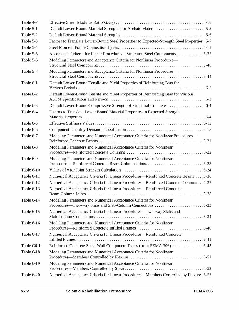
Table 4-7 Effective Shear Modulus Ratio(G/G0) . . . . . . . . . . . . . . . . . . . . . . . . . . . . . . . . . . . . . . . . .4-18
Table 5-1 Default Lower-Bound Material Strengths for Archaic Materials . . . . . . . . . . . . . . . . . . . . . .5-5
Table 5-2 Default Lower-Bound Material Strengths. . . . . . . . . . . . . . . . . . . . . . . . . . . . . . . . . . . . . . . .5-6
Table 5-3 Factors to Translate Lower-Bound Steel Properties to Expected-Strength Steel Properties .5-7
Table 5-4 Steel Moment Frame Connection Types. . . . . . . . . . . . . . . . . . . . . . . . . . . . . . . . . . . . . . . .5-11
Table 5-5 Acceptance Criteria for Linear Procedures—Structural Steel Components . . . . . . . . . . . . .5-35
Table 5-6 Modeling Parameters and Acceptance Criteria for Nonlinear Procedures—Structural Steel Components. . . . . . . . . . . . . . . . . . . . . . . . . . . . . . . . . . . . . . . . . . . . . . . . .5-40
Table 5-7 Modeling Parameters and Acceptance Criteria for Nonlinear Procedures—Structural Steel Components. . . . . . . . . . . . . . . . . . . . . . . . . . . . . . . . . . . . . . . . . . . . . . . . .5-44
Table 6-1 Default Lower-Bound Tensile and Yield Properties of Reinforcing Bars for Various Periods . . . . . . . . . . . . . . . . . . . . . . . . . . . . . . . . . . . . . . . . . . . . . . . . . . . . . . . . . . . .6-2
Table 6-2 Default Lower-Bound Tensile and Yield Properties of Reinforcing Bars for Various ASTM Specifications and Periods . . . . . . . . . . . . . . . . . . . . . . . . . . . . . . . . . . . . . . . . . . . . .6-3
Table 6-3 Default Lower-Bound Compressive Strength of Structural Concrete . . . . . . . . . . . . . . . . . .6-4
Table 6-4 Factors to Translate Lower Bound Material Properties to Expected StrengthMaterial Properties . . . . . . . . . . . . . . . . . . . . . . . . . . . . . . . . . . . . . . . . . . . . . . . . . . . . . . . . .6-4
Table 6-5 Effective Stiffness Values. . . . . . . . . . . . . . . . . . . . . . . . . . . . . . . . . . . . . . . . . . . . . . . . . . .6-12
Table 6-6 Component Ductility Demand Classification . . . . . . . . . . . . . . . . . . . . . . . . . . . . . . . . . . . .6-15
Table 6-7 Modeling Parameters and Numerical Acceptance Criteria for Nonlinear Procedures—Reinforced Concrete Beams . . . . . . . . . . . . . . . . . . . . . . . . . . . . . . . . . . . . . . . . . . . . . . . . .6-21
Table 6-8 Modeling Parameters and Numerical Acceptance Criteria for Nonlinear Procedures—Reinforced Concrete Columns . . . . . . . . . . . . . . . . . . . . . . . . . . . . . . . . . . . .6-22
Table 6-9 Modeling Parameters and Numerical Acceptance Criteria for Nonlinear Procedures—Reinforced Concrete Beam-Column Joints. . . . . . . . . . . . . . . . . . . . . . . . . . .6-23
Table 6-10 Values of γ for Joint Strength Calculation . . . . . . . . . . . . . . . . . . . . . . . . . . . . . . . . . . . . . .6-24
Table 6-11 Numerical Acceptance Criteria for Linear Procedures—Reinforced Concrete Beams . . . .6-26
Table 6-12 Numerical Acceptance Criteria for Linear Procedures—Reinforced Concrete Columns . .6-27
Table 6-13 Numerical Acceptance Criteria for Linear Procedures—Reinforced ConcreteBeam-Column Joints. . . . . . . . . . . . . . . . . . . . . . . . . . . . . . . . . . . . . . . . . . . . . . . . . . . . . . .6-28
Table 6-14 Modeling Parameters and Numerical Acceptance Criteria for Nonlinear Procedures—Two-way Slabs and Slab-Column Connections . . . . . . . . . . . . . . . . . . . . . . .6-33
Table 6-15 Numerical Acceptance Criteria for Linear Procedures—Two-way Slabs andSlab-Column Connections . . . . . . . . . . . . . . . . . . . . . . . . . . . . . . . . . . . . . . . . . . . . . . . . . .6-34
Table 6-16 Modeling Parameters and Numerical Acceptance Criteria for Nonlinear Procedures—Reinforced Concrete Infilled Frames . . . . . . . . . . . . . . . . . . . . . . . . . . . . . . .6-40
Table 6-17 Numerical Acceptance Criteria for Linear Procedures—Reinforced ConcreteInfilled Frames . . . . . . . . . . . . . . . . . . . . . . . . . . . . . . . . . . . . . . . . . . . . . . . . . . . . . . . . . . .6-41
Table C6-1 Reinforced Concrete Shear Wall Component Types (from FEMA 306) . . . . . . . . . . . . . . .6-45
Table 6-18 Modeling Parameters and Numerical Acceptance Criteria for Nonlinear Procedures—Members Controlled by Flexure . . . . . . . . . . . . . . . . . . . . . . . . . . . . . . . . . .6-51
Table 6-19 Modeling Parameters and Numerical Acceptance Criteria for Nonlinear Procedures—Members Controlled by Shear. . . . . . . . . . . . . . . . . . . . . . . . . . . . . . . . . . . . .6-52
Table 6-20 Numerical Acceptance Criteria for Linear Procedures—Members Controlled by Flexure .6-53
xxiv Seismic Rehabilitation Prestandard FEMA 356
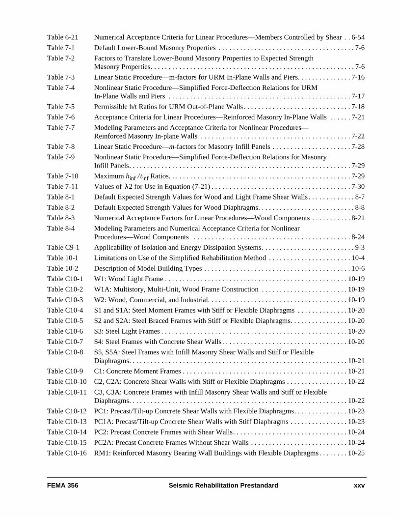
Table 6-21 Numerical Acceptance Criteria for Linear Procedures—Members Controlled by Shear . . 6-54
Table 7-1 Default Lower-Bound Masonry Properties . . . . . . . . . . . . . . . . . . . . . . . . . . . . . . . . . . . . . . 7-6
Table 7-2 Factors to Translate Lower-Bound Masonry Properties to Expected Strength Masonry Properties. . . . . . . . . . . . . . . . . . . . . . . . . . . . . . . . . . . . . . . . . . . . . . . . . . . . . . . . . 7-6
Table 7-3 Linear Static Procedure—m-factors for URM In-Plane Walls and Piers. . . . . . . . . . . . . . . 7-16
Table 7-4 Nonlinear Static Procedure—Simplified Force-Deflection Relations for URM In-Plane Walls and Piers . . . . . . . . . . . . . . . . . . . . . . . . . . . . . . . . . . . . . . . . . . . . . . . . . . . 7-17
Table 7-5 Permissible h/t Ratios for URM Out-of-Plane Walls . . . . . . . . . . . . . . . . . . . . . . . . . . . . . . 7-18
Table 7-6 Acceptance Criteria for Linear Procedures—Reinforced Masonry In-Plane Walls . . . . . . 7-21
Table 7-7 Modeling Parameters and Acceptance Criteria for Nonlinear Procedures—Reinforced Masonry In-plane Walls . . . . . . . . . . . . . . . . . . . . . . . . . . . . . . . . . . . . . . . . . . 7-22
Table 7-8 Linear Static Procedure—m-factors for Masonry Infill Panels . . . . . . . . . . . . . . . . . . . . . . 7-28
Table 7-9 Nonlinear Static Procedure—Simplified Force-Deflection Relations for Masonry Infill Panels. . . . . . . . . . . . . . . . . . . . . . . . . . . . . . . . . . . . . . . . . . . . . . . . . . . . . . . . . . . . . . 7-29
Table 7-10 Maximum hinf / tinf Ratios. . . . . . . . . . . . . . . . . . . . . . . . . . . . . . . . . . . . . . . . . . . . . . . . . . . 7-29
Table 7-11 Values of λ2 for Use in Equation (7-21) . . . . . . . . . . . . . . . . . . . . . . . . . . . . . . . . . . . . . . . 7-30
Table 8-1 Default Expected Strength Values for Wood and Light Frame Shear Walls . . . . . . . . . . . . . 8-7
Table 8-2 Default Expected Strength Values for Wood Diaphragms. . . . . . . . . . . . . . . . . . . . . . . . . . . 8-8
Table 8-3 Numerical Acceptance Factors for Linear Procedures—Wood Components . . . . . . . . . . . 8-21
Table 8-4 Modeling Parameters and Numerical Acceptance Criteria for Nonlinear Procedures—Wood Components . . . . . . . . . . . . . . . . . . . . . . . . . . . . . . . . . . . . . . . . . . . . 8-24
Table C9-1 Applicability of Isolation and Energy Dissipation Systems. . . . . . . . . . . . . . . . . . . . . . . . . . 9-3
Table 10-1 Limitations on Use of the Simplified Rehabilitation Method . . . . . . . . . . . . . . . . . . . . . . . 10-4
Table 10-2 Description of Model Building Types . . . . . . . . . . . . . . . . . . . . . . . . . . . . . . . . . . . . . . . . . 10-6
Table C10-1 W1: Wood Light Frame . . . . . . . . . . . . . . . . . . . . . . . . . . . . . . . . . . . . . . . . . . . . . . . . . . . 10-19
Table C10-2 W1A: Multistory, Multi-Unit, Wood Frame Construction . . . . . . . . . . . . . . . . . . . . . . . . 10-19
Table C10-3 W2: Wood, Commercial, and Industrial. . . . . . . . . . . . . . . . . . . . . . . . . . . . . . . . . . . . . . . 10-19
Table C10-4 S1 and S1A: Steel Moment Frames with Stiff or Flexible Diaphragms . . . . . . . . . . . . . . 10-20
Table C10-5 S2 and S2A: Steel Braced Frames with Stiff or Flexible Diaphragms. . . . . . . . . . . . . . . . 10-20
Table C10-6 S3: Steel Light Frames . . . . . . . . . . . . . . . . . . . . . . . . . . . . . . . . . . . . . . . . . . . . . . . . . . . . 10-20
Table C10-7 S4: Steel Frames with Concrete Shear Walls . . . . . . . . . . . . . . . . . . . . . . . . . . . . . . . . . . . 10-20
Table C10-8 S5, S5A: Steel Frames with Infill Masonry Shear Walls and Stiff or Flexible Diaphragms. . . . . . . . . . . . . . . . . . . . . . . . . . . . . . . . . . . . . . . . . . . . . . . . . . . . . . . . . . . . . 10-21
Table C10-9 C1: Concrete Moment Frames . . . . . . . . . . . . . . . . . . . . . . . . . . . . . . . . . . . . . . . . . . . . . . 10-21
Table C10-10 C2, C2A: Concrete Shear Walls with Stiff or Flexible Diaphragms . . . . . . . . . . . . . . . . . 10-22
Table C10-11 C3, C3A: Concrete Frames with Infill Masonry Shear Walls and Stiff or Flexible Diaphragms. . . . . . . . . . . . . . . . . . . . . . . . . . . . . . . . . . . . . . . . . . . . . . . . . . . . . . . . . . . . . 10-22
Table C10-12 PC1: Precast/Tilt-up Concrete Shear Walls with Flexible Diaphragms. . . . . . . . . . . . . . . 10-23
Table C10-13 PC1A: Precast/Tilt-up Concrete Shear Walls with Stiff Diaphragms . . . . . . . . . . . . . . . . 10-23
Table C10-14 PC2: Precast Concrete Frames with Shear Walls. . . . . . . . . . . . . . . . . . . . . . . . . . . . . . . . 10-24
Table C10-15 PC2A: Precast Concrete Frames Without Shear Walls . . . . . . . . . . . . . . . . . . . . . . . . . . . 10-24
Table C10-16 RM1: Reinforced Masonry Bearing Wall Buildings with Flexible Diaphragms . . . . . . . . 10-25
FEMA 356 Seismic Rehabilitation Prestandard xxv
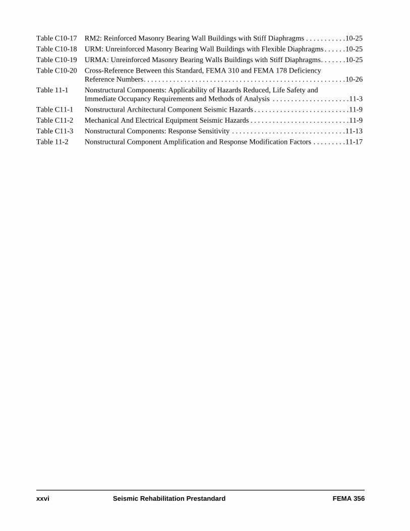
Table C10-17 RM2: Reinforced Masonry Bearing Wall Buildings with Stiff Diaphragms . . . . . . . . . . .10-25
Table C10-18 URM: Unreinforced Masonry Bearing Wall Buildings with Flexible Diaphragms . . . . . .10-25
Table C10-19 URMA: Unreinforced Masonry Bearing Walls Buildings with Stiff Diaphragms. . . . . . .10-25
Table C10-20 Cross-Reference Between this Standard, FEMA 310 and FEMA 178 DeficiencyReference Numbers. . . . . . . . . . . . . . . . . . . . . . . . . . . . . . . . . . . . . . . . . . . . . . . . . . . . . . .10-26
Table 11-1 Nonstructural Components: Applicability of Hazards Reduced, Life Safety and Immediate Occupancy Requirements and Methods of Analysis . . . . . . . . . . . . . . . . . . . . .11-3
Table C11-1 Nonstructural Architectural Component Seismic Hazards . . . . . . . . . . . . . . . . . . . . . . . . . .11-9
Table C11-2 Mechanical And Electrical Equipment Seismic Hazards . . . . . . . . . . . . . . . . . . . . . . . . . . .11-9
Table C11-3 Nonstructural Components: Response Sensitivity . . . . . . . . . . . . . . . . . . . . . . . . . . . . . . .11-13
Table 11-2 Nonstructural Component Amplification and Response Modification Factors . . . . . . . . .11-17
xxvi Seismic Rehabilitation Prestandard FEMA 356
1. Rehabilitation Requirements
1.1 ScopeThis Prestandard for the Seismic Rehabilitation of Buildings, referred to herein as “this standard,” specifies nationally applicable provisions for the rehabilitation of buildings to improve seismic performance. It is intended for use by code officials in directed seismic rehabilitation programs, or for reference by building owners and design professionals in voluntary rehabilitation efforts.
This chapter sets forth requirements for selecting a Rehabilitation Objective and conducting the seismic rehabilitation process.
Symbols, acronyms, definitions, and references used throughout this standard are cited separately in sections located at the end of this standard.
C1.1 ScopeThis standard is intended to serve as a nationally applicable tool for design professionals, code officials, and building owners undertaking the seismic rehabilitation of existing buildings. It consists of two parts: provisions, which contain the technical requirements, and commentary, intended to explain the provisions. Commentary for a given section is located in a shaded box immediately following the section, and is identified by the same section number preceded by the letter “C.”
It is expected that most buildings rehabilitated in accordance with this standard would perform within the desired levels when subjected to the design earthquakes. However, compliance with the standard does not guarantee such performance. The practice of earthquake engineering is rapidly evolving, and both our understanding of the behavior of buildings subjected to strong earthquakes and our ability to predict this behavior are advancing. In the future, new knowledge and technology will provide more reliable methods of accomplishing these goals.
The procedures contained in this standard are specifically applicable to the rehabilitation of existing buildings and are, in general, more appropriate for that purpose than are new building codes. New building codes are primarily intended to regulate the design and construction of new buildings; as such, they include many provisions that encourage the development of designs with features important for good seismic performance, including regular configuration, structural continuity, ductile detailing, and materials of appropriate quality. Many existing buildings were designed and constructed without these features and contain characteristics such as unfavorable configuration and poor detailing that preclude application of building code provisions for their seismic rehabilitation.
While it is intended to be used as a follow-up to a previous seismic evaluation, this standard can also be used as an evaluation tool that ascertains compliance with a selected rehabilitation objective. A FEMA 310, Tier 3 evaluation is an example of this use. It should be noted, however, that an evaluation using this standard may be more stringent than other evaluation methodologies because the provisions have been calibrated for use in design. Historically, criteria for evaluation have been set lower than those for design to minimize the need to strengthen buildings that would otherwise have only modest deficiencies.
The expertise of the design professional in earthquake engineering is an important prerequisite for the appropriate use of this standard in assisting a building owner to select voluntary seismic criteria or to design and analyze seismic rehabilitation projects.
This standard is intended to be generally applicable to seismic rehabilitation of all buildings—regardless of importance, occupancy, historic status, or other classifications of use. However, application of these provisions should be coordinated with other requirements that may be in effect, such as ordinances governing historic structures or hospital construction. In addition to the direct effects of ground shaking, this standard also considers the effects of local geologic site hazards such as liquefaction.
FEMA 356 Seismic Rehabilitation Prestandard 1-1
Chapter 1: Rehabilitation Requirements
1.2 Design BasisSeismic rehabilitation of buildings shall comply with the design criteria and procedures of this standard for achieving the performance-based Rehabilitation Objectives defined in Section 1.4. The use of alternative performance-based criteria and procedures shall be permitted as approved by the code official.
This standard applies to the seismic rehabilitation of both the overall structural system of a building and its nonstructural components including ceilings, partitions, mechanical, electrical, and plumbing systems.
With careful extrapolation, the procedures of this standard may also be applied to many nonbuilding structures such as pipe racks, steel storage racks, structural towers for tanks and vessels, piers, wharves, and electrical power generating facilities. However, the applicability of these procedures has not been fully examined for every type of structure, particularly those that have generally been covered by specialized codes or standards, such as bridges and nuclear power plants.
In addition to techniques for increasing the strength and ductility of systems, this standard provides techniques for reducing seismic demand, such as the introduction of isolation or damping devices. Design of new buildings and evaluation of components for gravity and wind forces in the absence of earthquake demands are beyond the scope of this standard.
This standard does not explicitly address the determination of whether or not a rehabilitation project should be undertaken for a particular building. Guidance on the use of this standard in voluntary or directed risk-mitigation programs is provided in Appendix A. Determining when these provisions should be required or desired is beyond the scope of this standard. Once the decision to rehabilitate a building has been made, this standard can be referenced for detailed engineering guidance on how to conduct a seismic rehabilitation analysis and design.
Featured in this standard are descriptions of damage states in relation to specific performance levels. These descriptions are intended to aid design professionals and owners in selecting appropriate performance levels for rehabilitation design. They are not intended to be used for condition assessment of earthquake-damaged buildings. Although there may be similarities between these damage descriptions and those used for post-earthquake damage assessment, many factors enter into the processes of assessing seismic performance. No single parameter in this standard should be cited as defining either a performance level or the safety or usefulness of an earthquake-damaged building.
Techniques for repair of earthquake- damaged buildings are not included in this standard, but are referenced in the commentary of Chapters 5 through 8 when such guidelines exist. If the mechanical properties of repaired components are known, acceptability criteria for use with this standard can be either deduced by comparison with other similar components, or derived. Any combination of repaired elements, undamaged existing elements, and new elements can be modeled using this standard, and each checked against performance level acceptance criteria.
C1.2 Design BasisProvisions of this standard for seismic rehabilitation are based on a performance-based design methodology that differs from seismic design procedures for the design of new buildings currently specified in national building codes and standards.
The framework in which these requirements are specified is purposefully broad so that Rehabilitation Objectives can accommodate buildings of different types, that satisfy a variety of performance levels, and consider the variation of seismic hazards across the United States and Territories.
The provisions and commentary of this standard are primarily based on the FEMA 273 Guidelines with limited material taken from the FEMA 274 Commentary. This standard is intended to supersede FEMA 273, but FEMA 274 remains a valid explanation for the provisions in this standard unless indicated otherwise in the relevant commentary of this standard. For this reason, section numbers in this standard remain essentially the same as in FEMA 273, with the exception of Chapters 1 and 2, which were reorganized for clarity.
1-2 Seismic Rehabilitation Prestandard FEMA 356

Chapter 1: Rehabilitation Requirements
FEMA 273 was developed by a large team of specialists in earthquake engineering and seismic rehabilitation. The most advanced analytical techniques considered practical for production use have been incorporated. The acceptance criteria have been specified using actual laboratory test results, where available, supplemented by the engineering judgment of various development teams. Certain buildings damaged in the 1994 Northridge earthquake and a limited number of designs using codes for new buildings have been checked using the procedures of FEMA 273. A comprehensive program of case studies was undertaken by FEMA in 1998 to test more thoroughly the various analysis techniques and acceptability criteria. The results of this study are reported in FEMA 343, Case Studies: An Assessment of the NEHRP Guidelines for the Seismic Rehabilitation of Buildings. The results of the FEMA 343 case studies have been incorporated in the provisions of this standard, where possible. Similarly, information from FEMA 350, FEMA 351, and other reports published by the SAC Joint Venture project, formed as a result of the Northridge steel moment frame damage, has been incorporated where applicable. Engineering judgment should be exercised in determining the applicability of various analysis techniques and material acceptability criteria in each situation.
The commentary to this standard contains specific references to many other documents. In addition, this standard is also related generically to the following publications.
1. FEMA 222A and 223A, NEHRP Recommended Provisions for Seismic Regulations for New Buildings, 1994 Edition. For the purposes of the design of new components, this standard has been designed to be as compatible as possible with the companion Provisions for new buildings and its reference design documents. Detailed references to the use of specific sections of the Provisions document will be found in subsequent sections of this standard.
2. FEMA 302 and 303, 1997 NEHRP Recommended Provisions for Seismic Regulations for New Buildings and Other Structures referred to herein as the 1997 NEHRP Recommended Provisions.
3. FEMA 237, Development of Guidelines for Seismic Rehabilitation of Buildings, Phase I: Issues Identification and Resolution, which underwent an American Society of Civil Engineers (ASCE) consensus approval process, provided policy direction for this standard.
4. ATC-28-2, Proceedings of the Workshop to Resolve Seismic Rehabilitation Sub-issues provided recommendations to the writers of this standard on more detailed sub-issues.
5. FEMA 172, NEHRP Handbook of Techniques for the Seismic Rehabilitation of Existing Buildings, originally produced by URS/Blume and reviewed by BSSC, contains construction techniques for implementing engineering solutions to the seismic deficiencies of existing buildings.
6. FEMA 178, NEHRP Handbook for the Seismic Evaluation of Existing Buildings, which was originally developed by ATC and underwent the consensus approval process of the BSSC, covered the subject of evaluating existing buildings to determine if they are seismically deficient in terms of life safety. This document has been updated by FEMA as a prestandard, FEMA 310, Handbook for the Seismic Evaluation of Existing Buildings, which underwent an ASCE consensus approval process. (The model building types and other information from FEMA 310 are used or referred to extensively in this standard in Chapter 10.)
7. FEMA 156 and 157, Typical Costs for Seismic Rehabilitation of Existing Buildings, Second Edition, reports statistical analysis of the costs of rehabilitation of over 2,000 buildings based on construction costs or detailed studies. Several different seismic zones and performance levels are included in the data. Since the data were developed in 1994, none of the data are based on buildings rehabilitated specifically in accordance with the FEMA 273 Guidelines document. Performance Levels defined in this standard are not intended to be significantly different from parallel levels used previously, and costs still should be reasonably representative.
8. FEMA 275, Planning for Seismic Rehabilitation: Societal Issues, discusses societal and implementation issues associated with rehabilitation and describes several case histories.
FEMA 356 Seismic Rehabilitation Prestandard 1-3

Chapter 1: Rehabilitation Requirements
1.3 Seismic Rehabilitation ProcessSeismic rehabilitation of an existing building shall be conducted in accordance with the process outlined in Sections 1.3.1 through 1.3.6. Before embarking on a rehabilitation design, seismic deficiencies shall have been identified through a prior seismic evaluation performed using an evaluation methodology considering a combination of building performance and seismic hazard.
9. FEMA 276, Guidelines for the Seismic Rehabilitation of Buildings: Example Applications, intended as a companion document to FEMA 273 and FEMA 274, describes examples of buildings that have been seismically rehabilitated in various seismic regions and for different Rehabilitation Objectives. Costs of the work are given and references made to FEMA 156 and 157. Because this document is based on previous case histories, none of the examples was rehabilitated specifically in accordance with this standard. However, Performance Levels defined in this standard are not intended to be significantly different from parallel levels used previously, and the case studies are therefore considered representative.
10.ATC 40, Seismic Evaluation and Retrofit of Concrete Buildings, incorporates performance levels almost identical to those shown in Table C1-8 and employs “pushover” nonlinear analysis techniques. The capacity spectrum method for determining the displacement demand is treated in detail. This document covers only concrete buildings.
C1.3 Seismic Rehabilitation ProcessThe steps are presented in this section in the order in which they would typically be followed in the rehabilitation process. However, the criteria for performing these steps are presented in a somewhat different order to facilitate presentation of the concepts.
Figure C1-1 depicts the rehabilitation process specified in this standard and shows specific chapter references in parentheses at points where input from this standard is to be obtained.
This standard requires the building owner or the code official to select a Rehabilitation Objective for a building that has been previously identified as needing seismic rehabilitation.
Prior to embarking on a rehabilitation program, an evaluation should be performed to determine whether the building, in its existing condition, has the desired seismic performance capability. FEMA 310 is an example of an evaluation methodology that may be used for this purpose. It should be noted, however, that a building may meet certain performance objectives using the methodology of FEMA 310, but may not meet those same performance objectives when an evaluation is performed using the procedures of this standard. This is largely because FEMA 310 is specifically intended to accept somewhat greater levels of damage within each performance level than permitted by this standard, which is consistent with the historic practice of evaluating existing buildings for slightly lower criteria than those used for design of new buildings. FEMA 310 quantifies this difference with the use of a 0.75 factor on demands when using this standard in a Tier 3 evaluation. This essentially lowers the reliability of achieving the selected performance level from about 90% to 60%. This practice minimizes the need to rehabilitate structures with relatively modest deficiencies relative to the desired performance level.
1-4 Seismic Rehabilitation Prestandard FEMA 356

Chapter 1: Rehabilitation Requirements
Figure C1-1 Rehabilitation Process
6.2A Section 1.3.6.2: Prepare Construction Documents of Acceptable Rehabilitation
• Develop construction documents
• Begin rehabilitation• Exercise quality control
4A Simplified Rehabilitation (Chapters 2, 10 and 11)• Identify building model type • Consider deficiencies• Select full or partial rehabilitation
(Note: Simplified Rehabilitation shall be used for Limited Objectives only.)
4B Systematic Rehabilitation (Chapters 2 through 9 and 11)• Consider deficiencies• Select rehabilitation strategy (Chapter 2)• Select analysis procedure (Chapters 2 and 3)• Consider general requirements (Chapter 2)
4C Other Choices (not in this standard)
• Reduce occupancy• Demolish
5A Section 1.3.5:Perform Rehabilitation Design• Determine and design
rehabilitation measures to meet applicable FEMA 310 requirements
6A Section 1.3.6:Verify Rehabilitation Design• Reevaluate building to assure
that rehabilitation measures remove all deficiencies without creating new ones
• Review for economic acceptability
6B Section 1.3.6:Verify Rehabilitation Design• Apply component acceptance criteria (Chapters 2 through 9
and 11)• Review for conformance with requirements of Chapter 2• Review for economic acceptability
6.1B Section 1.3.6.1: Redesign Unacceptable Rehabilitation
• Return to 4B to revise analysis and design or to 2 to reconsider Rehabilitation Objective
6.2B Section 1.3.6.2: Prepare Construction Documents of Acceptable Rehabilitation
• Develop construction documents
• Begin rehabilitation• Exercise quality control
6.1A Section 1.3.6.1: Redesign Unacceptable Rehabilitation
• Return to 4A to reconsider Rehabilitation Objective or to 5A to revise corrective measures
5B Section 1.3.5: Perform Rehabilitation Design• Develop mathematical model (Chapters 3 through 9 for stiffness
and strength)• Perform force and deformation response evaluation
(Chapters 2 through 9 and 11)• Size elements, components, and connections
(Chapters 2, 5 through 9, and 11)
4 Section 1.3.4: Select Rehabilitation Method
3 Section 1.3.3: Obtain As-Built Information (Chapter 2)
Interest in reducing seismic risk
1 Section 1.3.1: Review Initial Considerations
• Structural characteristics (Chapter 2)• Site seismic hazards (Chapters 1 and 4)• Results from prior seismic evaluations (Section 1.2)• Occupancy (not considered in this standard)• Historic status (Appendix A)• Economic considerations (Section C1.2.6.2)• Societal issues: (Appendix A)• Local jurisdictional requirements (not considered in this standard)
2 Section 1.3.2: Select Rehabilitation Objective
• Target Building Performance level (Section 1.5)• Seismic Hazard (Section 1.6)
Prior Seismic Evaluation (Section 1.2)
FEMA 356 Seismic Rehabilitation Prestandard 1-5
Chapter 1: Rehabilitation Requirements
1.3.1 Review Initial Considerations
The design professional shall review initial considerations with the building owner or code official to determine any restrictions that exist on the design of rehabilitation measures. Initial considerations shall include structural characteristics of the building, seismic hazards including geologic site hazards known to be present at the site, results of prior seismic evaluations, building use and occupancy requirements, historic status, economic considerations, societal issues, and local jurisdictional requirements.
C1.3.1 Review Initial Considerations
The process of building rehabilitation will be simplified and made more efficient if information that significantly affects the rehabilitation design is obtained and considered prior to beginning the process. Rehabilitation requirements mandated by local jurisdictions would be particularly important to determine in the initial stages of a project.
The building owner should be aware of the range of costs and impacts of rehabilitation, including both the variation associated with different Rehabilitation Objectives and the potential additional costs often associated with seismic rehabilitation, such as other life safety upgrades, hazardous material removal, work associated with the Americans with Disabilities Act, and nonseismic building remodeling. Also to be considered are potential federal tax incentives for the rehabilitation of historic buildings and for some other older nonresidential buildings.
Seismic hazards other than ground shaking may exist at the building site. The risk and possible extent of damage from geologic site hazards identified in Section 4.2.2 should be considered before undertaking a rehabilitation aimed solely at reducing damage due to shaking. In some cases it may be feasible to mitigate the site hazard or rehabilitate the building and still meet the selected performance level. In other cases the risk due to site hazards may be so extreme and difficult to control that rehabilitation is neither cost-effective nor feasible.
The use of the building must be considered in weighing the significance of potential temporary or permanent disruptions associated with various risk mitigation schemes. Other limitations on modifications to the building due to historic or aesthetic features must also be understood. The historic status of every building at least 50 years old should be determined (see Appendix A, Section A.6, Considerations for Historic Buildings). This determination should be made early as it could influence the choices of rehabilitation approaches and techniques.
There are many ways to reduce seismic risk, whether the risk is to property, life safety, or post- earthquake use of the building. The occupancy of vulnerable buildings can be reduced, redundant facilities can be provided, and nonhistoric buildings can be demolished and replaced. The risks posed by nonstructural components and contents can be reduced. Seismic site hazards other than shaking can be mitigated.
Most often, however, when all alternatives are considered, the options of modifying the building to reduce the risk of damage should be studied. Such corrective measures include stiffening or strengthening the structure, adding local elements to eliminate irregularities or tie the structure together, reducing the demand on the structure through the use of seismic isolation or energy dissipation devices, and reducing the height or mass of the structure. Rehabilitation strategies are discussed in Chapter 2.
1-6 Seismic Rehabilitation Prestandard FEMA 356
Chapter 1: Rehabilitation Requirements
1.3.2 Select Rehabilitation Objective
The building owner or code official shall select a seismic Rehabilitation Objective for the building as specified in Section 1.4. The selection of a Rehabilitation Objective shall consist of the selection of a target Building Performance Level from a range of performance levels defined in Section 1.5 and on the selection of an anticipated Earthquake Hazard Level from a range of seismic hazards defined in Section 1.6.
1.3.3 Obtain As-Built Information
Available as-built information for the building shall be obtained and a site visit shall be conducted as specified in Section 2.2.
1.3.4 Select Rehabilitation Method
An applicable rehabilitation method shall be determined in accordance with Section 2.3.
1.3.5 Perform Rehabilitation Design
Rehabilitation measures shall be designed using the applicable rehabilitation method.
1.3.6 Verify Rehabilitation Design
The rehabilitation design shall be verified to meet the requirements of this standard through an analysis of the building, including rehabilitation measures. The analysis shall be consistent with the procedures for the applicable rehabilitation method specified in Section 2.3. A separate analytical evaluation shall be performed for each combination of building performance and seismic hazard specified in the selected Rehabilitation Objective.
1.3.6.1 Redesign Unacceptable Rehabilitation
If the rehabilitation design fails to comply with the acceptance criteria for the selected Rehabilitation Objective, the rehabilitation measures shall be redesigned or an alternative rehabilitation strategy shall be implemented. This process shall be repeated until the design is in compliance with the acceptance criteria for the selected Rehabilitation Objective.
C1.3.2 Select Rehabilitation Objective
The concepts and terminology of performance-based design are new and should be carefully studied and discussed with building owners before use. The terminology used for target Building Performance Levels is intended to represent goals of design. The actual ground motion will seldom be comparable to that specified in the Rehabilitation Objective, so in most events, designs targeted at various damage states may only determine relative performance. Even given a ground motion similar to that specified in the Rehabilitation Objective and used in design, variations from stated performance objectives should be expected and compliance with this standard should not be considered a guarantee of performance. Variations in actual performance could be associated with unknown geometry and member sizes in existing buildings, deterioration of materials, incomplete site data, variation of ground motion that can occur within a small area, and incomplete knowledge and simplifications related to modeling and analysis. Information on the expected reliability of achieving various target Building Performance Levels when the requirements are followed can be found in Chapter 2 of FEMA 274.
C1.3.4 Select Rehabilitation Method
Rehabilitation can consist of the Simplified Rehabilitation Method or the Systematic Rehabilitation Method. These methods are defined in Section 2.3 and further explained in the associated commentary of that section.
FEMA 356 Seismic Rehabilitation Prestandard 1-7

Chapter 1: Rehabilitation Requirements
1.3.6.2 Prepare Construction Documents of Acceptable Rehabilitation
If the rehabilitation design meets the acceptance criteria for the selected Rehabilitation Objective, and the decision is made to proceed with the rehabilitation, construction documents shall be prepared and shall include requirements for construction quality assurance in accordance with Section 2.7.
1.4 Rehabilitation ObjectivesA seismic Rehabilitation Objective shall be selected for the building, consisting of one or more rehabilitation goals. Each goal shall consist of a target Building Performance Level defined in Section 1.5 and an Earthquake Hazard Level defined in Section 1.6. Goals shall be selected considering basic, enhanced, or limited objectives defined in Sections 1.4.1 through 1.4.3.
C1.3.6.2 Prepare Construction Documents of Acceptable Rehabilitation
At this stage, a cost estimate can be made to review the economic acceptability of the design. Cost estimating or reviewing economic acceptability of the rehabilitation design is not included in the standard, but is an essential part of the rehabilitation process shown in Figure C1-1.
Construction costs are discussed in Example Applications, FEMA 276 and Typical Costs for Seismic Rehabilitation, FEMA 156 and 157.
If the design proves uneconomical or otherwise not feasible, further refinement may be considered in analysis, a different rehabilitation scheme may be designed or a different Rehabilitation Objective may be considered.
Section 2.7 specifies provisions for a quality assurance program during the construction or implementation of the rehabilitation design. Other aspects of the implementation process, including details of the preparation of construction documents, obtaining a building permit, selection of a contractor, details of historic preservation techniques for particular kinds of materials, and financing are not covered in this standard.
C1.4 Rehabilitation ObjectivesRecommendations regarding the selection of a Rehabilitation Objective for any building are beyond the scope of this standard. FEMA 274 discusses issues to consider when combining various performance and seismic hazard levels. It should be noted that not all combinations constitute reasonable or cost-effective Rehabilitation Objectives. This standard is written under the premise that greater flexibility is required in seismic rehabilitation than in the design of new buildings. However, given that flexibility, once a Rehabilitation Objective is selected, this standard provides internally consistent procedures with the necessary specificity to perform a rehabilitation analysis and design.
Building performance can be described qualitatively in terms of the safety afforded building occupants during and after the event; the cost and feasibility of restoring the building to pre-earthquake condition; the length of time the building is removed from service to effect repairs; and economic, architectural, or historic impacts on the larger community. These performance characteristics are directly related to the extent of damage that would be sustained by the building.
In this standard, the extent of damage to a building is categorized as a Building Performance Level. A broad range of target Building Performance Levels may be selected when determining Rehabilitation Objectives.
Probabilistic Earthquake Hazard Levels frequently used in this standard and their corresponding mean return periods (the average number of years between events of similar severity) are as follows:
These mean return periods are typically rounded to 75, 225, 500, and 2,500 years, respectively.
Earthquake Having Probability of Exceedance
Mean Return Period (years)
50%/50 year 72
20%/50 year 225
10%/50 year 474
2%/50 year 2,475
1-8 Seismic Rehabilitation Prestandard FEMA 356

Chapter 1: Rehabilitation Requirements
1.4.1 Basic Safety Objective
The Basic Safety Objective (BSO) is a Rehabilitation Objective that achieves the dual rehabilitation goals of Life Safety Building Performance Level (3-C) for the BSE-1 Earthquake Hazard Level and Collapse Prevention Building Performance Level (5-E) for the BSE-2 Earthquake Hazard Level.
1.4.2 Enhanced Rehabilitation Objectives
Rehabilitation that provides building performance exceeding that of the BSO is termed an Enhanced Objective. Enhanced Rehabilitation Objectives shall be achieved using one or a combination of the following two methods:
1. By designing for target Building Performance Levels that exceed those of the BSO at either the BSE-1 or BSE-2 hazard levels, or both.
2. By designing for the target Building Performance Levels of the BSO using an Earthquake Hazard Level that exceeds either the BSE-1 or BSE-2 hazard levels, or both.
The Rehabilitation Objective selected as a basis for design will determine, to a great extent, the cost and feasibility of any rehabilitation project, as well as the benefit to be obtained in terms of improved safety, reduction in property damage, and interruption of use in the event of future earthquakes. Table C1-1 indicates the range of Rehabilitation Objectives that may be used in this standard.
Table C1-1 Rehabilitation Objectives
Target Building Performance Levels
Op
erat
ion
al P
erfo
rman
ce
Lev
el (
1-A
)
Imm
edia
te O
ccu
pan
cy P
erfo
rman
ce
Lev
el (
1-B
)
Lif
e S
afet
y P
erfo
rman
ce
Lev
el (
3-C
)
Co
llaps
e P
reve
nti
on
Per
form
ance
L
evel
(5-
E)
Ear
thq
uak
e H
azar
d
Lev
el
50%/50 year a b c d
20%/50 year e f g h
BSE-1(~10%/50 year)
i j k l
BSE-2(~2%/50 year)
m n o p
Notes:
1. Each cell in the above matrix represents a discrete Rehabilitation Objective.
2. The Rehabilitation Objectives in the matrix above may be used to represent the three specific Rehabilitation Objectives defined in Sections 1.4.1, 1.4.2, and 1.4.3, as follows:
k + p = Basic Safety Objective (BSO)k + p + any of a, e, i, b, f, j, or n = Enhanced Objectiveso alone or n alone or m alone = Enhanced Objectivek alone or p alone = Limited Objectivesc, g, d, h, l = Limited Objectives
C1.4.1 Basic Safety Objective
The BSO is intended to approximate the earthquake risk to life safety traditionally considered acceptable in the United States. Buildings meeting the BSO are expected to experience little damage from relatively frequent, moderate earthquakes, but significantly more damage and potential economic loss from the most severe and infrequent earthquakes that could affect them. The level of damage and potential economic loss experienced by buildings rehabilitated to the BSO may be greater than that expected in properly designed and constructed new buildings.
C1.4.2 Enhanced Rehabilitation Objectives
Enhanced Rehabilitation Objectives can be obtained by designing for higher target Building Performance Levels (method 1) or by designing using higher Earthquake Hazard Levels (method 2) or any combination of these two methods.
FEMA 356 Seismic Rehabilitation Prestandard 1-9
Chapter 1: Rehabilitation Requirements
1.4.3 Limited Rehabilitation Objectives
Rehabilitation that provides building performance less than that of the BSO is termed a Limited Objective. Limited Rehabilitation Objectives shall be achieved using Reduced Rehabilitation specified in Section 1.4.3.1 or Partial Rehabilitation specified in Section 1.4.3.2, and shall comply with the following conditions:
1. The rehabilitation measures shall not result in a reduction in the performance level of the existing building;
2. The rehabilitation measures shall not create a new structural irregularity or make an existing structural irregularity more severe;
3. The rehabilitation measures shall not result in an increase in the seismic forces to any component that is deficient in capacity to resist these forces;
4. All new or rehabilitated structural components and elements shall be detailed and connected to the existing structure in compliance with the requirements of this standard.
1.4.3.1 Reduced Rehabilitation Objective
Rehabilitation that addresses the entire building structural and nonstructural systems, but uses a lower seismic hazard or lower target Building Performance Level than the BSO, is termed Reduced Rehabilitation Objective. Reduced Rehabilitation shall be designed for one or more of the following objectives:
1. Life Safety Building Performance Level (3-C) for earthquake demands that are less severe (more probable) than the BSE-1;
2. Collapse Prevention Building Performance Level (5-E) for earthquake demands that are less severe (more probable) than the BSE-2;
3. Building Performance Levels 4-C, 4-D, 4-E, 5-C, 5-D, 5-E, 6-D, or 6-E for BSE-1 or less severe (more probable) earthquake demands.
1.4.3.2 Partial Rehabilitation Objective
Rehabilitation that addresses a portion of the building without rehabilitating the complete lateral-force-resisting system is termed Partial Rehabilitation. A Partial Rehabilitation shall be designed and constructed considering future completion of a Rehabilitation Objective intended to improve the performance of the entire structure.
1.5 Target Building Performance Levels
A target Building Performance Level shall consist of a combination of a Structural Performance Level selected from the levels specified in Section 1.5.1 and a Nonstructural Performance Level selected from the levels specified in Section 1.5.2. The target Building Performance Level shall be designated alphanumerically in accordance with Section 1.5.3.
C1.5 Target Building Performance Levels
Building performance is a combination of the performance of both structural and nonstructural components. Table C1-2 describes the approximate limiting levels of structural and nonstructural damage that may be expected of buildings rehabilitated to the levels defined in the standard. On average, the expected damage would be less. For comparative purposes, the estimated performance of a new building subjected to the BSE-1 level of shaking is indicated. Performance descriptions in Table C1-2 are estimates rather than precise predictions, and variation among buildings of the same target Building Performance Level must be expected.
1-10 Seismic Rehabilitation Prestandard FEMA 356

Chapter 1: Rehabilitation Requirements
1.5.1 Structural Performance Levels and Ranges
The Structural Performance Level of a building shall be selected from four discrete Structural Performance Levels and two intermediate Structural Performance Ranges defined in this section.
The discrete Structural Performance Levels are Immediate Occupancy (S-1), Life Safety (S-3), Collapse Prevention (S-5), and Not Considered (S-6). Design procedures and acceptance criteria corresponding to these Structural Performance Levels shall be as specified in Chapters 4 through 10.
The intermediate Structural Performance Ranges are the Damage Control Range (S-2) and the Limited Safety Range (S-4). Acceptance criteria for performance within the Damage Control Structural Performance Range shall be obtained by interpolating the acceptance criteria provided for the Immediate Occupancy and Life Safety Structural Performance Levels. Acceptance criteria for performance within the Limited Safety Structural Performance Range shall be obtained by interpolating the acceptance criteria provided for the Life Safety and Collapse Prevention Structural Performance Levels.
1.5.1.1 Immediate Occupancy Structural Performance Level (S-1)
Structural Performance Level S-1, Immediate Occupancy, shall be defined as the post-earthquake damage state that remains safe to occupy, essentially retains the pre-earthquake design strength and stiffness of the structure, and is in compliance with the acceptance criteria specified in this standard for this Structural Performance Level.
Building performance in this standard is expressed in terms of target Building Performance Levels. These target Building Performance Levels are discrete damage states selected from among the infinite spectrum of possible damage states that buildings could experience during an earthquake. The particular damage states identified as target Building Performance Levels in this standard have been selected because they have readily identifiable consequences associated with the post-earthquake disposition of the building that are meaningful to the building community. These include the ability to resume normal functions within the building, the advisability of post-earthquake occupancy, and the risk to life safety.
Due to inherent uncertainties in prediction of ground motion and analytical prediction of building performance, some variation in actual performance should be expected. Compliance with this standard should not be considered a guarantee of performance. Information on the reliability of achieving various Performance Levels can be found Chapter 2 of FEMA 274).
C1.5.1 Structural Performance Levels and Ranges
A wide range of structural performance requirements could be desired by individual building owners. The four Structural Performance Levels defined in this standard have been selected to correlate with the most commonly specified structural performance requirements. The two Structural Performance Ranges permit users with other requirements to customize their building Rehabilitation Objectives.
Table C1-3 relates these Structural Performance Levels to the limiting damage states for common vertical elements of lateral-force-resisting systems. Table C1-4 relates these Structural Performance Levels to the limiting damage states for common horizontal elements of building lateral-force-resisting systems. Later sections of this standard specify design parameters (such as m-factors, component capacities, and inelastic deformation demands) specified as limiting values for attaining these Structural Performance Levels for a known earthquake demand.
The drift values given in Table C1-3 are typical values provided to illustrate the overall structural response associated with various Structural Performance Levels. They are not provided in these tables as drift limit requirements for this standard, and do not supersede component or element deformation limits that are specified in Chapters 4 through 9, and 11.
The expected post-earthquake state of the buildings described in these tables is for comparative purposes and should not be used in the post-earthquake safety evaluation process.
FEMA 356 Seismic Rehabilitation Prestandard 1-11
Chapter 1: Rehabilitation Requirements
1.5.1.2 Damage Control Structural Performance Range (S-2)
Structural Performance Range S-2, Damage Control, shall be defined as the continuous range of damage states between the Life Safety Structural Performance Level (S-3) and the Immediate Occupancy Structural Performance Level (S-1).
1.5.1.3 Life Safety Structural Performance Level (S-3)
Structural Performance Level S-3, Life Safety, shall be defined as the post-earthquake damage state that includes damage to structural components but retains a margin against onset of partial or total collapse in compliance with the acceptance criteria specified in this standard for this Structural Performance Level.
1.5.1.4 Limited Safety Structural Performance Range (S-4)
Structural Performance Range S-4, Limited Safety, shall be defined as the continuous range of damage states between the Life Safety Structural Performance Level (S-3) and the Collapse Prevention Structural Performance Level (S-5).
1.5.1.5 Collapse Prevention Structural Performance Level (S-5)
Structural Performance Level S-5, Collapse Prevention, shall be defined as the post-earthquake damage state that includes damage to structural components such that the structure continues to support gravity loads but retains no margin against collapse in compliance with the acceptance criteria specified in this standard for this Structural Performance Level.
C1.5.1.1 Immediate Occupancy Structural Performance Level (S-1)
Structural Performance Level S-1, Immediate Occupancy, means the post-earthquake damage state in which only very limited structural damage has occurred. The basic vertical- and lateral-force-resisting systems of the building retain nearly all of their pre-earthquake strength and stiffness. The risk of life-threatening injury as a result of structural damage is very low, and although some minor structural repairs may be appropriate, these would generally not be required prior to reoccupancy.
C1.5.1.2 Damage Control Structural Performance Range (S-2)
Design for the Damage Control Structural Performance Range may be desirable to minimize repair time and operation interruption, as a partial means of protecting valuable equipment and contents, or to preserve important historic features when the cost of design for immediate occupancy is excessive.
C1.5.1.3 Life Safety Structural Performance Level (S-3)
Structural Performance Level S-3, Life Safety, means the post-earthquake damage state in which significant damage to the structure has occurred, but some margin against either partial or total structural collapse remains. Some structural elements and components are severely damaged, but this has not resulted in large falling debris hazards, either within or outside the building. Injuries may occur during the earthquake; however, the overall risk of life-threatening injury as a result of structural damage is expected to be low. It should be possible to repair the structure; however, for economic reasons this may not be practical. While the damaged structure is not an imminent collapse risk, it would be prudent to implement structural repairs or install temporary bracing prior to reoccupancy.
1-12 Seismic Rehabilitation Prestandard FEMA 356
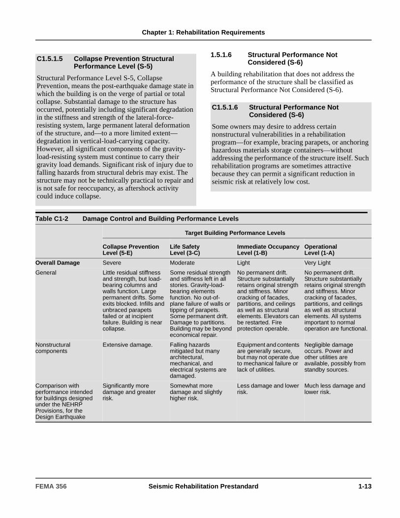
Chapter 1: Rehabilitation Requirements
1.5.1.6 Structural Performance Not Considered (S-6)
A building rehabilitation that does not address the performance of the structure shall be classified as Structural Performance Not Considered (S-6).
C1.5.1.5 Collapse Prevention Structural Performance Level (S-5)
Structural Performance Level S-5, Collapse Prevention, means the post-earthquake damage state in which the building is on the verge of partial or total collapse. Substantial damage to the structure has occurred, potentially including significant degradation in the stiffness and strength of the lateral-force-resisting system, large permanent lateral deformation of the structure, and—to a more limited extent—degradation in vertical-load-carrying capacity. However, all significant components of the gravity-load-resisting system must continue to carry their gravity load demands. Significant risk of injury due to falling hazards from structural debris may exist. The structure may not be technically practical to repair and is not safe for reoccupancy, as aftershock activity could induce collapse.
C1.5.1.6 Structural Performance Not Considered (S-6)
Some owners may desire to address certain nonstructural vulnerabilities in a rehabilitation program—for example, bracing parapets, or anchoring hazardous materials storage containers—without addressing the performance of the structure itself. Such rehabilitation programs are sometimes attractive because they can permit a significant reduction in seismic risk at relatively low cost.
Table C1-2 Damage Control and Building Performance Levels
Target Building Performance Levels
Collapse Prevention Level (5-E)
Life SafetyLevel (3-C)
Immediate OccupancyLevel (1-B)
OperationalLevel (1-A)
Overall Damage Severe Moderate Light Very Light
General Little residual stiffness and strength, but load-bearing columns and walls function. Large permanent drifts. Some exits blocked. Infills and unbraced parapets failed or at incipient failure. Building is near collapse.
Some residual strength and stiffness left in all stories. Gravity-load-bearing elements function. No out-of-plane failure of walls or tipping of parapets. Some permanent drift. Damage to partitions. Building may be beyond economical repair.
No permanent drift. Structure substantially retains original strength and stiffness. Minor cracking of facades, partitions, and ceilings as well as structural elements. Elevators can be restarted. Fire protection operable.
No permanent drift. Structure substantially retains original strength and stiffness. Minor cracking of facades, partitions, and ceilings as well as structural elements. All systems important to normal operation are functional.
Nonstructural components
Extensive damage. Falling hazards mitigated but many architectural, mechanical, and electrical systems are damaged.
Equipment and contents are generally secure, but may not operate due to mechanical failure or lack of utilities.
Negligible damage occurs. Power and other utilities are available, possibly from standby sources.
Comparison with performance intended for buildings designed under the NEHRP Provisions, for the Design Earthquake
Significantly more damage and greater risk.
Somewhat more damage and slightly higher risk.
Less damage and lower risk.
Much less damage and lower risk.
FEMA 356 Seismic Rehabilitation Prestandard 1-13

Chapter 1: Rehabilitation Requirements
Table C1-3 Structural Performance Levels and Damage1, 2, 3—Vertical Elements
Elements Type
Structural Performance Levels
Collapse Prevention S-5
Life Safety S-3
Immediate Occupancy S-1
Concrete Frames Primary Extensive cracking and hinge formation in ductile elements. Limited cracking and/or splice failure in some nonductile columns. Severe damage in short columns.
Extensive damage to beams. Spalling of cover and shear cracking (<1/8" width) for ductile columns. Minor spalling in nonductile columns. Joint cracks<1/8" wide.
Minor hairline cracking. Limited yielding possible at a few locations. No crushing (strains below 0.003).
Secondary Extensive spalling in columns (limited shortening) and beams. Severe joint damage. Some reinforcing buckled.
Extensive cracking and hinge formation in ductile elements. Limited cracking and/or splice failure in some nonductile columns. Severe damage in short columns.
Minor spalling in a few places in ductile columns and beams. Flexural cracking in beams and columns. Shear cracking in joints <1/16" width.
Drift 4% transientor permanent
2% transient;1% permanent
1% transient; negligible permanent
Steel Moment Frames Primary Extensive distortion of beams and column panels. Many fractures at moment connections, but shear connections remain intact.
Hinges form. Local buckling of some beam elements. Severe joint distortion; isolated moment connection fractures, but shear connections remain intact. A few elements may experience partial fracture.
Minor local yielding at a few places. No fractures. Minor buckling or observable permanent distortion of members.
Secondary Same as primary. Extensive distortion of beams and column panels. Many fractures at moment connections, but shear connections remain intact.
Same as primary.
Drift 5% transient or permanent
2.5% transient;1% permanent
0.7% transient; negligible permanent
Braced Steel Frames Primary Extensive yielding and buckling of braces. Many braces and their connections may fail.
Many braces yield or buckle but do not totally fail. Many connections may fail.
Minor yielding or buckling of braces.
Secondary Same as primary. Same as primary. Same as primary.
Drift 2% transientor permanent
1.5% transient; 0.5% permanent
0.5% transient; negligible permanent
1-14 Seismic Rehabilitation Prestandard FEMA 356

Chapter 1: Rehabilitation Requirements
Concrete Walls Primary Major flexural and shear cracks and voids. Sliding at joints. Extensive crushing and buckling of reinforcement. Failure around openings. Severe boundary element damage. Coupling beams shattered and virtually disintegrated.
Some boundary element stress, including limited buckling of reinforcement. Some sliding at joints. Damage around openings. Some crushing and flexural cracking. Coupling beams: extensive shear and flexural cracks; some crushing, but concrete generally remains in place.
Minor hairline cracking of walls, <1/16" wide. Coupling beams experience cracking <1/8" width.
Secondary Panels shattered and virtually disintegrated.
Major flexural and shear cracks. Sliding at joints. Extensive crushing. Failure around openings. Severe boundary element damage. Coupling beams shattered and virtually disintegrated.
Minor hairline cracking of walls. Some evidence of sliding at construction joints. Coupling beams experience cracks <1/8" width. Minor spalling.
Drift 2% transientor permanent
1% transient; 0.5% permanent
0.5% transient; negligible permanent
Unreinforced Masonry Infill Walls
Primary Extensive cracking and crushing; portions of face course shed.
Extensive cracking and some crushing but wall remains in place. No falling units. Extensive crushing and spalling of veneers at corners of openings.
Minor (<1/8" width) cracking of masonry infills and veneers. Minor spalling in veneers at a few corner openings.
Secondary Extensive crushing and shattering; some walls dislodge.
Same as primary. Same as primary.
Drift 0.6% transientor permanent
0.5% transient; 0.3% permanent
0.1% transient; negligible permanent
UnreinforcedMasonry (Noninfill) Walls
Primary Extensive cracking; face course and veneer may peel off. Noticeable in-plane and out-of-plane offsets.
Extensive cracking. Noticeable in-plane offsets of masonry and minor out-of-plane offsets.
Minor (<1/8" width) cracking of veneers. Minor spalling in veneers at a few corner openings. No observable out-of-plane offsets.
Secondary Nonbearing panels dislodge.
Same as primary. Same as primary.
Drift 1% transientor permanent
0.6% transient; 0.6% permanent
0.3% transient; 0.3% permanent
Table C1-3 Structural Performance Levels and Damage1, 2, 3—Vertical Elements (continued)
Elements Type
Structural Performance Levels
Collapse Prevention S-5
Life Safety S-3
Immediate Occupancy S-1
FEMA 356 Seismic Rehabilitation Prestandard 1-15
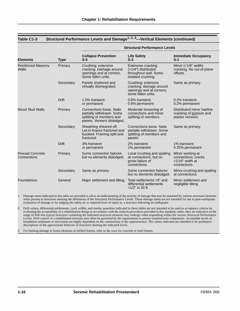
Chapter 1: Rehabilitation Requirements
Reinforced Masonry Walls
Primary Crushing; extensive cracking. Damage around openings and at corners. Some fallen units.
Extensive cracking (<1/4") distributed throughout wall. Some isolated crushing.
Minor (<1/8" width) cracking. No out-of-plane offsets.
Secondary Panels shattered and virtually disintegrated.
Crushing; extensive cracking; damage around openings and at corners; some fallen units.
Same as primary.
Drift 1.5% transient or permanent
0.6% transient; 0.6% permanent
0.2% transient; 0.2% permanent
Wood Stud Walls Primary Connections loose. Nails partially withdrawn. Some splitting of members and panels. Veneers dislodged.
Moderate loosening of connections and minor splitting of members.
Distributed minor hairline cracking of gypsum and plaster veneers.
Secondary Sheathing sheared off. Let-in braces fractured and buckled. Framing split and fractured.
Connections loose. Nails partially withdrawn. Some splitting of members and panels.
Same as primary.
Drift 3% transient or permanent
2% transient; 1% permanent
1% transient; 0.25% permanent
Precast Concrete Connections
Primary Some connection failures but no elements dislodged.
Local crushing and spalling at connections, but no gross failure of connections.
Minor working at connections; cracks <1/16" width at connections.
Secondary Same as primary. Some connection failures but no elements dislodged.
Minor crushing and spalling at connections.
Foundations General Major settlement and tilting. Total settlements <6" and differential settlements <1/2" in 30 ft.
Minor settlement and negligible tilting.
1. Damage states indicated in this table are provided to allow an understanding of the severity of damage that may be sustained by various structural elements when present in structures meeting the definitions of the Structural Performance Levels. These damage states are not intended for use in post-earthquake evaluation of damage or for judging the safety of, or required level of repair to, a structure following an earthquake.
2. Drift values, differential settlements, crack widths, and similar quantities indicated in these tables are not intended to be used as acceptance criteria for evaluating the acceptability of a rehabilitation design in accordance with the analysis procedures provided in this standard; rather, they are indicative of the range of drift that typical structures containing the indicated structural elements may undergo when responding within the various Structural Performance Levels. Drift control of a rehabilitated structure may often be governed by the requirements to protect nonstructural components. Acceptable levels of foundation settlement or movement are highly dependent on the construction of the superstructure. The values indicated are intended to be qualitative descriptions of the approximate behavior of structures meeting the indicated levels.
3. For limiting damage to frame elements of infilled frames, refer to the rows for concrete or steel frames.
Table C1-3 Structural Performance Levels and Damage1, 2, 3—Vertical Elements (continued)
Elements Type
Structural Performance Levels
Collapse Prevention S-5
Life Safety S-3
Immediate Occupancy S-1
1-16 Seismic Rehabilitation Prestandard FEMA 356

Chapter 1: Rehabilitation Requirements
1.5.2 Nonstructural Performance Levels
The Nonstructural Performance Level of a building shall be selected from five discrete Nonstructural Performance Levels, consisting of Operational (N-A), Immediate Occupancy (N-B), Life Safety (N-C), Hazards Reduced (N-D), and Not Considered (N-E). Design procedures and acceptance criteria for rehabilitation of nonstructural components shall comply with the requirements of Chapters 10 and 11.
Table C1-4 Structural Performance Levels and Damage1, 2—Horizontal Elements
Element
Structural Performance Levels
Collapse Prevention S-5
Life Safety S-3
Immediate Occupancy S-1
Metal Deck Diaphragms Large distortion with buckling of some units and tearing of many welds and seam attachments.
Some localized failure of welded connections of deck to framing and between panels. Minor local buckling of deck.
Connections between deck units and framing intact. Minor distortions.
Wood Diaphragms Large permanent distortion with partial withdrawal of nails and extensive splitting of elements.
Some splitting at connections. Loosening of sheathing. Observable withdrawal of fasteners. Splitting of framing and sheathing.
No observable loosening or withdrawal of fasteners. No splitting of sheathing or framing.
Concrete Diaphragms Extensive crushing and observable offset across many cracks.
Extensive cracking (<1/4" width). Local crushing and spalling.
Distributed hairline cracking. Some minor cracks of larger size (<1/8” width).
Precast Diaphragms Connections between units fail. Units shift relative to each other. Crushing and spalling at joints.
Extensive cracking (<1/4” width). Local crushing and spalling.
Some minor cracking along joints.
1. Damage states indicated in this table are provided to allow an understanding of the severity of damage that may be sustained by various structural elements when present in structures meeting the definitions of the Structural Performance Levels. These damage states are not intended for use in post-earthquake evaluation of damage or for judging the safety of, or required level of repair to, a structure following an earthquake.
2. Drift values, differential settlements, crack widths, and similar quantities indicated in these tables are not intended to be used as acceptance criteria for evaluating the acceptability of a rehabilitation design in accordance with the analysis procedures provided in this standard; rather, they are indicative of the range of drift that typical structures containing the indicated structural elements may undergo when responding within the various Structural Performance Levels. Drift control of a rehabilitated structure may often be governed by the requirements to protect nonstructural components. Acceptable levels of foundation settlement or movement are highly dependent on the construction of the superstructure. The values indicated are intended to be qualitative descriptions of the approximate behavior of structures meeting the indicated levels.
C1.5.2 Nonstructural Performance Levels
Nonstructural Performance Levels other than Not Considered (N-E) are summarized in Table C1-5 through C1-7. Nonstructural components addressed in this standard include architectural components such as partitions, exterior cladding, and ceilings; and mechanical and electrical components, including HVAC systems, plumbing, fire suppression systems, and lighting. Occupant contents and furnishings (such as inventory and computers) are included in these tables for some levels but are generally not covered with specific requirements.
FEMA 356 Seismic Rehabilitation Prestandard 1-17
Chapter 1: Rehabilitation Requirements
1.5.2.1 Operational Nonstructural Performance Level (N-A)
Nonstructural Performance Level N-A, Operational, shall be defined as the post-earthquake damage state in which the nonstructural components are able to support the pre-earthquake functions present in the building.
1.5.2.2 Immediate Occupancy Nonstructural Performance Level (N-B)
Nonstructural Performance Level N-B, Immediate Occupancy, shall be defined as the post-earthquake damage state that includes damage to nonstructural components, but building access and life safety systems—including doors, stairways, elevators, emergency lighting, fire alarms, and suppression systems—generally remain available and operable, provided that power is available.
1.5.2.3 Life Safety Nonstructural Performance Level (N-C)
Nonstructural Performance Level N-C, Life Safety, shall be defined as the post-earthquake damage state that includes damage to nonstructural components but the damage is non-life threatening.
C1.5.2.1 Operational Nonstructural Performance Level (N-A)
At this level, most nonstructural systems required for normal use of the building—including lighting, plumbing, HVAC, and computer systems—are functional, although minor cleanup and repair of some items may be required. This Nonstructural Performance Level requires considerations beyond those that are normally within the sole province of the structural engineer. In addition to assuring that nonstructural components are properly mounted and braced within the structure, it is often necessary to provide emergency standby utilities. It also may be necessary to perform rigorous qualification testing of the ability of key electrical and mechanical equipment items to function during or after strong shaking.
Specific design procedures and acceptance criteria for this Nonstructural Performance Level are not included in this standard. Users wishing to design for this Nonstructural Performance Level will need to refer to appropriate criteria from other sources (such as equipment manufacturers’ data) to ensure the performance of mechanical and electrical systems.
C1.5.2.2 Immediate Occupancy Nonstructural Performance Level (N-B)
Minor window breakage and slight damage could occur to some components. Presuming that the building is structurally safe, occupants could safely remain in the building, although normal use may be impaired and some cleanup and inspection may be required. In general, components of mechanical and electrical systems in the building are structurally secured and should be able to function if necessary utility service is available. However, some components may experience misalignments or internal damage and be nonoperable. Power, water, natural gas, communications lines, and other utilities required for normal building use may not be available. The risk of life-threatening injury due to nonstructural damage is very low.
C1.5.2.3 Life Safety Nonstructural Performance Level (N-C)
Nonstructural Performance Level C, Life Safety, is the post-earthquake damage state in which potentially significant and costly damage has occurred to nonstructural components but they have not become dislodged and fallen, threatening life safety either inside or outside the building. Egress routes within the building are not extensively blocked, but may be impaired by lightweight debris. HVAC, plumbing, and fire suppression systems may have been damaged, resulting in local flooding as well as loss of function. While injuries may occur during the earthquake from the failure of nonstructural components, overall, the risk of life-threatening injury is very low. Restoration of the nonstructural components may take extensive effort.
1-18 Seismic Rehabilitation Prestandard FEMA 356

Chapter 1: Rehabilitation Requirements
1.5.2.4 Hazards Reduced Nonstructural Performance Level (N-D)
Nonstructural Performance Level N-D, Hazards Reduced, shall be defined as the post-earthquake damage state that includes damage to nonstructural components that could potentially create falling hazards, but high hazard nonstructural components identified in Table 11-1 are secured and will not fall into areas of public assembly. Preservation of egress, protection of fire suppression systems, and similar life-safety issues are not addressed in this Nonstructural Performance Level.
1.5.2.5 Nonstructural Performance Not Considered (N-E)
A building rehabilitation that does not address nonstructural components shall be classified as Nonstructural Performance Not Considered (N-E).
C1.5.2.4 Hazards Reduced Nonstructural Performance Level (N-D)
Nonstructural Performance Level D, Hazards Reduced, represents a post-earthquake damage state in which extensive damage has occurred to nonstructural components, but large or heavy items that pose a high risk of falling hazard to a large number of people—such as parapets, cladding panels, heavy plaster ceilings, or storage racks—are prevented from falling. The hazards associated with exterior elements along portions of the exterior of the building that are available for public occupancy have been reduced. While isolated serious injury could occur from falling debris, failures that could injure large numbers of persons—either inside or outside the structure—should be avoided.
Nonstructural components that are small, lightweight, or close to the ground may fall, but should not cause serious injury. Larger nonstructural components in areas that are less likely to be populated may also fall.
The intent of the Hazards Reduced Performance Level is to address significant nonstructural hazards without needing to rehabilitate all of the nonstructural components in a building. When using this performance level, it will generally be appropriate to consider Hazards Reduced Performance as equivalent to Life Safety Performance for the most hazardous, highest risk subset of the nonstructural components in the building.
C1.5.2.5 Nonstructural Performance Not Considered (N-E)
In some cases, the decision to rehabilitate the structure may be made without addressing the vulnerabilities of nonstructural components. It may be desirable to do this when rehabilitation must be performed without interruption of building operation. In some cases, it is possible to perform all or most of the structural rehabilitation from outside occupied building areas. Extensive disruption of normal operation may be required to perform nonstructural rehabilitation. Also, since many of the most severe hazards to life safety occur as a result of structural vulnerabilities, some municipalities may wish to adopt rehabilitation ordinances that require structural rehabilitation only.
FEMA 356 Seismic Rehabilitation Prestandard 1-19

Chapter 1: Rehabilitation Requirements
Table C1-5 Nonstructural Performance Levels and Damage1—Architectural Components
Component
Nonstructural Performance Levels
Hazards Reduced2
N-DLife Safety
N-CImmediate Occupancy
N-BOperational
N-A
Cladding Severe distortion in connections. Distributed cracking, bending, crushing, and spalling of cladding elements. Some fracturing of cladding, but panels do not fall in areas of public assembly.
Severe distortion in connections. Distributed cracking, bending, crushing, and spalling of cladding elements. Some fracturing of cladding, but panels do not fall.
Connections yield; minor cracks (<1/16" width) or bending in cladding.
Connections yield; minor cracks (<1/16" width) or bending in cladding.
Glazing General shattered glass and distorted frames in unoccupied areas. Extensive cracked glass; little broken glass in occupied areas.
Extensive cracked glass; little broken glass.
Some cracked panes; none broken.
Some cracked panes; none broken.
Partitions Distributed damage; some severe cracking, crushing, and racking in some areas.
Distributed damage; some severe cracking, crushing, and racking in some areas.
Cracking to about 1/16" width at openings. Minor crushing and cracking at corners.
Cracking to about 1/16" width at openings. Minor crushing and cracking at corners.
Ceilings Extensive damage. Dropped suspended ceiling tiles. Moderate cracking in hard ceilings.
Extensive damage. Dropped suspended ceiling tiles. Moderate cracking in hard ceilings.
Minor damage. Some suspended ceiling tiles disrupted. A few panels dropped. Minor cracking in hard ceilings.
Generally negligible damage. Isolated suspended panel dislocations, or cracks in hard ceilings.
Parapets & Ornamentation
Extensive damage; some falling in unoccupied areas.
Extensive damage; some falling in unoccupied areas.
Minor damage. Minor damage.
Canopies & Marquees Moderate damage. Moderate damage. Minor damage. Minor damage.
Chimneys & Stacks Extensive damage. No collapse.
Extensive damage. No collapse.
Minor cracking. Negligible damage.
Stairs & Fire Escapes Extensive racking. Loss of use.
Some racking and cracking of slabs. Usable.
Minor damage. Negligible damage.
Doors Distributed damage. Many racked and jammed doors.
Distributed damage. Some racked and jammed doors.
Minor damage. Doors operable.
Minor damage. Doors operable.
1. Damage states indicated in this table are provided to allow an understanding of the severity of damage that may be sustained by various nonstructural elements meeting the Nonstructural Performance Levels defined in this standard. These damage states are not intended for use in post-earthquake evaluation of damage or for judging the safety or required level of repair following an earthquake.
2. For the Hazards Reduced Performance Level, high hazard nonstructural components evaluated or rehabilitated to the Life Safety criteria will have Hazards Reduced performance identical to that expected for the Life Safety Performance Level.
1-20 Seismic Rehabilitation Prestandard FEMA 356
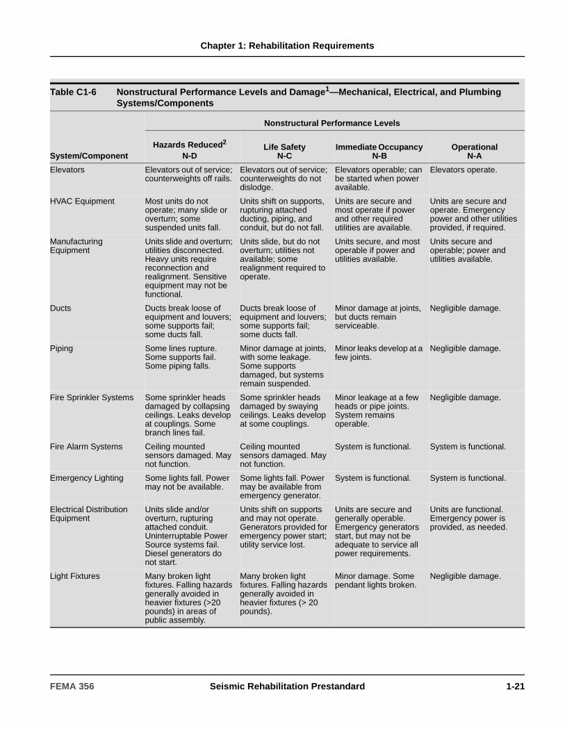
Chapter 1: Rehabilitation Requirements
Table C1-6 Nonstructural Performance Levels and Damage1—Mechanical, Electrical, and Plumbing Systems/Components
System/Component
Nonstructural Performance Levels
Hazards Reduced2
N-DLife Safety
N-CImmediate Occupancy
N-BOperational
N-A
Elevators Elevators out of service; counterweights off rails.
Elevators out of service; counterweights do not dislodge.
Elevators operable; can be started when power available.
Elevators operate.
HVAC Equipment Most units do not operate; many slide or overturn; some suspended units fall.
Units shift on supports, rupturing attached ducting, piping, and conduit, but do not fall.
Units are secure and most operate if power and other required utilities are available.
Units are secure and operate. Emergency power and other utilities provided, if required.
Manufacturing Equipment
Units slide and overturn; utilities disconnected. Heavy units require reconnection and realignment. Sensitive equipment may not be functional.
Units slide, but do not overturn; utilities not available; some realignment required to operate.
Units secure, and most operable if power and utilities available.
Units secure and operable; power and utilities available.
Ducts Ducts break loose of equipment and louvers; some supports fail; some ducts fall.
Ducts break loose of equipment and louvers; some supports fail; some ducts fall.
Minor damage at joints, but ducts remain serviceable.
Negligible damage.
Piping Some lines rupture. Some supports fail. Some piping falls.
Minor damage at joints, with some leakage. Some supports damaged, but systems remain suspended.
Minor leaks develop at a few joints.
Negligible damage.
Fire Sprinkler Systems Some sprinkler heads damaged by collapsing ceilings. Leaks develop at couplings. Some branch lines fail.
Some sprinkler heads damaged by swaying ceilings. Leaks develop at some couplings.
Minor leakage at a few heads or pipe joints. System remains operable.
Negligible damage.
Fire Alarm Systems Ceiling mounted sensors damaged. May not function.
Ceiling mounted sensors damaged. May not function.
System is functional. System is functional.
Emergency Lighting Some lights fall. Power may not be available.
Some lights fall. Power may be available from emergency generator.
System is functional. System is functional.
Electrical Distribution Equipment
Units slide and/or overturn, rupturing attached conduit. Uninterruptable Power Source systems fail. Diesel generators do not start.
Units shift on supports and may not operate. Generators provided for emergency power start; utility service lost.
Units are secure and generally operable. Emergency generators start, but may not be adequate to service all power requirements.
Units are functional. Emergency power is provided, as needed.
Light Fixtures Many broken light fixtures. Falling hazards generally avoided in heavier fixtures (>20 pounds) in areas of public assembly.
Many broken light fixtures. Falling hazards generally avoided in heavier fixtures (> 20 pounds).
Minor damage. Some pendant lights broken.
Negligible damage.
FEMA 356 Seismic Rehabilitation Prestandard 1-21
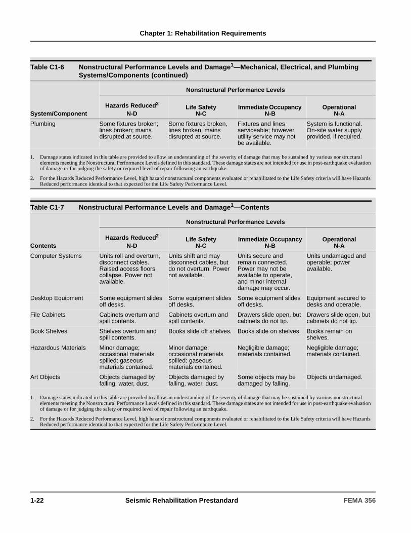
Chapter 1: Rehabilitation Requirements
Plumbing Some fixtures broken; lines broken; mains disrupted at source.
Some fixtures broken, lines broken; mains disrupted at source.
Fixtures and lines serviceable; however, utility service may not be available.
System is functional. On-site water supply provided, if required.
1. Damage states indicated in this table are provided to allow an understanding of the severity of damage that may be sustained by various nonstructural elements meeting the Nonstructural Performance Levels defined in this standard. These damage states are not intended for use in post-earthquake evaluation of damage or for judging the safety or required level of repair following an earthquake.
2. For the Hazards Reduced Performance Level, high hazard nonstructural components evaluated or rehabilitated to the Life Safety criteria will have Hazards Reduced performance identical to that expected for the Life Safety Performance Level.
Table C1-7 Nonstructural Performance Levels and Damage1—Contents
Contents
Nonstructural Performance Levels
Hazards Reduced2
N-DLife Safety
N-CImmediate Occupancy
N-BOperational
N-A
Computer Systems Units roll and overturn, disconnect cables. Raised access floors collapse. Power not available.
Units shift and may disconnect cables, but do not overturn. Power not available.
Units secure and remain connected. Power may not be available to operate, and minor internal damage may occur.
Units undamaged and operable; power available.
Desktop Equipment Some equipment slides off desks.
Some equipment slides off desks.
Some equipment slides off desks.
Equipment secured to desks and operable.
File Cabinets Cabinets overturn and spill contents.
Cabinets overturn and spill contents.
Drawers slide open, but cabinets do not tip.
Drawers slide open, but cabinets do not tip.
Book Shelves Shelves overturn and spill contents.
Books slide off shelves. Books slide on shelves. Books remain on shelves.
Hazardous Materials Minor damage; occasional materials spilled; gaseous materials contained.
Minor damage; occasional materials spilled; gaseous materials contained.
Negligible damage; materials contained.
Negligible damage; materials contained.
Art Objects Objects damaged by falling, water, dust.
Objects damaged by falling, water, dust.
Some objects may be damaged by falling.
Objects undamaged.
1. Damage states indicated in this table are provided to allow an understanding of the severity of damage that may be sustained by various nonstructural elements meeting the Nonstructural Performance Levels defined in this standard. These damage states are not intended for use in post-earthquake evaluation of damage or for judging the safety or required level of repair following an earthquake.
2. For the Hazards Reduced Performance Level, high hazard nonstructural components evaluated or rehabilitated to the Life Safety criteria will have Hazards Reduced performance identical to that expected for the Life Safety Performance Level.
Table C1-6 Nonstructural Performance Levels and Damage1—Mechanical, Electrical, and Plumbing Systems/Components (continued)
System/Component
Nonstructural Performance Levels
Hazards Reduced2
N-DLife Safety
N-CImmediate Occupancy
N-BOperational
N-A
1-22 Seismic Rehabilitation Prestandard FEMA 356
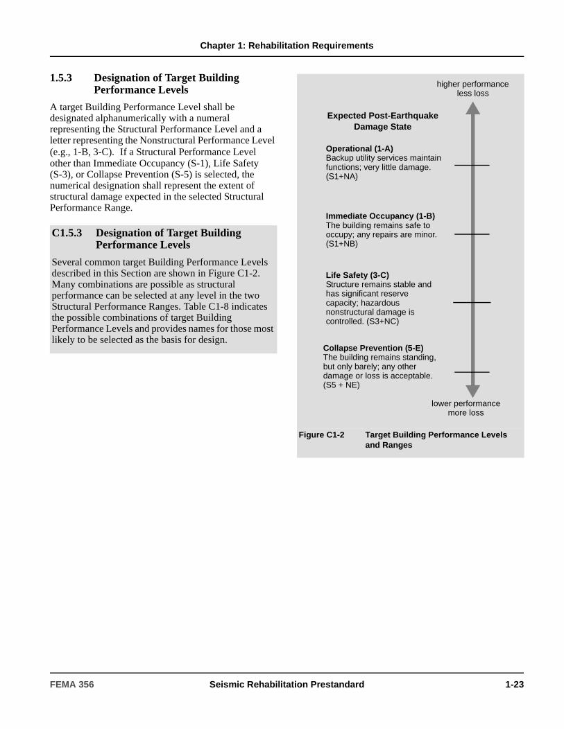
Chapter 1: Rehabilitation Requirements
1.5.3 Designation of Target Building Performance Levels
A target Building Performance Level shall be designated alphanumerically with a numeral representing the Structural Performance Level and a letter representing the Nonstructural Performance Level (e.g., 1-B, 3-C). If a Structural Performance Level other than Immediate Occupancy (S-1), Life Safety(S-3), or Collapse Prevention (S-5) is selected, the numerical designation shall represent the extent of structural damage expected in the selected Structural Performance Range.
C1.5.3 Designation of Target Building Performance Levels
Several common target Building Performance Levels described in this Section are shown in Figure C1-2. Many combinations are possible as structural performance can be selected at any level in the two Structural Performance Ranges. Table C1-8 indicates the possible combinations of target Building Performance Levels and provides names for those most likely to be selected as the basis for design.
Figure C1-2 Target Building Performance Levels and Ranges
Operational (1-A)Backup utility services maintain functions; very little damage. (S1+NA)
Immediate Occupancy (1-B)The building remains safe to occupy; any repairs are minor. (S1+NB)
Life Safety (3-C)Structure remains stable and has significant reserve capacity; hazardous nonstructural damage is controlled. (S3+NC)
Collapse Prevention (5-E)The building remains standing, but only barely; any other damage or loss is acceptable. (S5 + NE)
lower performancemore loss
higher performanceless loss
Expected Post-Earthquake Damage State
FEMA 356 Seismic Rehabilitation Prestandard 1-23
Chapter 1: Rehabilitation Requirements
1.5.3.1 Operational Building Performance Level (1-A)
To attain the Operational Building Performance Level (1-A), the structural components of the building shall meet the requirements of Section 1.5.1.1 for the Immediate Occupancy Structural Performance Level (S-1) and the nonstructural components shall meet the requirements of Section 1.5.2.1 for the Operational Nonstructural Performance Level (N-A).
1.5.3.2 Immediate Occupancy Building Performance Level (1-B)
To attain the Immediate Occupancy Building Performance Level (1-B), the structural components of the building shall meet the requirements of Section 1.5.1.1 for the Immediate Occupancy Structural Performance Level (S-1) and the nonstructural components of the building shall meet the requirements of Section 1.5.2.2 for the Immediate Occupancy Nonstructural Performance Level (N-B).
1.5.3.3 Life Safety Building Performance Level (3-C)
To attain the Life Safety Building Performance Level (3-C), the structural components of the building shall meet the requirements of Section 1.5.1.3 for the Life Safety Structural Performance Level (S-3) and the nonstructural components shall meet the requirements of Section 1.5.2.3 for the Life Safety Nonstructural Performance Level (N-C).
C1.5.3.1 Operational Building Performance Level (1-A)
Buildings meeting this target Building Performance Level are expected to sustain minimal or no damage to their structural and nonstructural components. The building is suitable for its normal occupancy and use, although possibly in a slightly impaired mode, with power, water, and other required utilities provided from emergency sources, and possibly with some non-essential systems not functioning. Buildings meeting this target Building Performance Level pose an extremely low risk to life safety.
Under very low levels of earthquake ground motion, most buildings should be able to meet or exceed this target Building Performance Level. Typically, however, it will not be economically practical to design for this target Building Performance Level for severe ground shaking, except for buildings that house essential services.
C1.5.3.2 Immediate Occupancy Building Performance Level (1-B)
Buildings meeting this target Building Performance Level are expected to sustain minimal or no damage to their structural elements and only minor damage to their nonstructural components. While it would be safe to reoccupy a building meeting this target Building Performance Level immediately following a major earthquake, nonstructural systems may not function, either because of the lack of electrical power or internal damage to equipment. Therefore, although immediate reoccupancy of the building is possible, it may be necessary to perform some cleanup and repair and await the restoration of utility service before the building can function in a normal mode. The risk to life safety at this target Building Performance Level is very low.
Many building owners may wish to achieve this level of performance when the building is subjected to moderate earthquake ground motion. In addition, some owners may desire such performance for very important buildings under severe earthquake ground shaking. This level provides most of the protection obtained under the Operational Building Performance Level without the cost of providing standby utilities and performing rigorous seismic qualification of equipment performance.
C1.5.3.3 Life Safety Building Performance Level (3-C)
Buildings meeting this level may experience extensive damage to structural and nonstructural components. Repairs may be required before reoccupancy of the building occurs, and repair may be deemed economically impractical. The risk to life safety in buildings meeting this target Building Performance Level is low.
1-24 Seismic Rehabilitation Prestandard FEMA 356
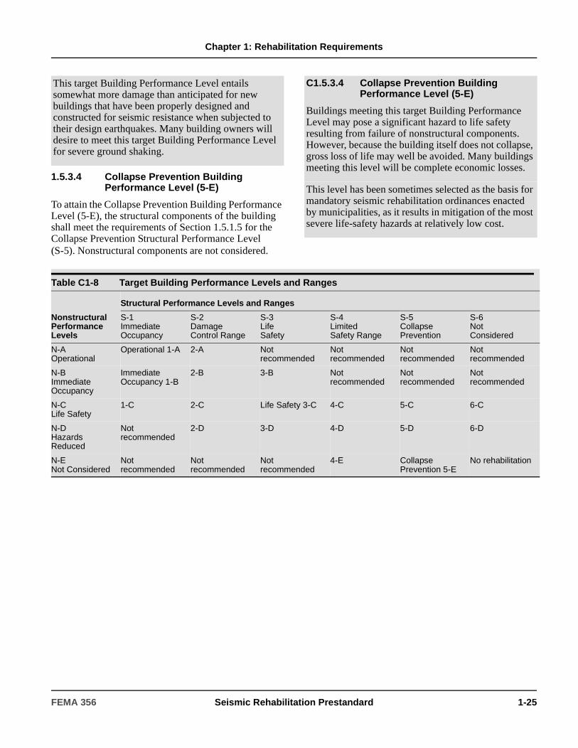
Chapter 1: Rehabilitation Requirements
1.5.3.4 Collapse Prevention Building Performance Level (5-E)
To attain the Collapse Prevention Building Performance Level (5-E), the structural components of the building shall meet the requirements of Section 1.5.1.5 for the Collapse Prevention Structural Performance Level (S-5). Nonstructural components are not considered.
This target Building Performance Level entails somewhat more damage than anticipated for new buildings that have been properly designed and constructed for seismic resistance when subjected to their design earthquakes. Many building owners will desire to meet this target Building Performance Level for severe ground shaking.
C1.5.3.4 Collapse Prevention Building Performance Level (5-E)
Buildings meeting this target Building Performance Level may pose a significant hazard to life safety resulting from failure of nonstructural components. However, because the building itself does not collapse, gross loss of life may well be avoided. Many buildings meeting this level will be complete economic losses.
This level has been sometimes selected as the basis for mandatory seismic rehabilitation ordinances enacted by municipalities, as it results in mitigation of the most severe life-safety hazards at relatively low cost.
Table C1-8 Target Building Performance Levels and Ranges
Nonstructural Performance Levels
Structural Performance Levels and Ranges
S-1 Immediate Occupancy
S-2 Damage Control Range
S-3 Life Safety
S-4 Limited Safety Range
S-5 Collapse Prevention
S-6 Not Considered
N-A Operational
Operational 1-A 2-A Not recommended
Not recommended
Not recommended
Not recommended
N-B Immediate Occupancy
Immediate Occupancy 1-B
2-B 3-B Not recommended
Not recommended
Not recommended
N-C Life Safety
1-C 2-C Life Safety 3-C 4-C 5-C 6-C
N-D Hazards Reduced
Not recommended
2-D 3-D 4-D 5-D 6-D
N-E Not Considered
Not recommended
Not recommended
Not recommended
4-E Collapse Prevention 5-E
No rehabilitation
FEMA 356 Seismic Rehabilitation Prestandard 1-25
Chapter 1: Rehabilitation Requirements
1.6 Seismic HazardSeismic hazard due to ground shaking shall be based on the location of the building with respect to causative faults, the regional and site-specific geologic characteristics, and a selected Earthquake Hazard Level. Assessment of seismic hazard due to earthquake-induced geologic site hazards shall be performed in accordance with Chapter 4.
Seismic hazard due to ground shaking shall be defined as acceleration response spectra or acceleration time-histories on either a probabilistic or deterministic basis. Acceleration response spectra shall be developed in accordance with either the General Procedure of Section 1.6.1 or the Site-Specific Procedure of Section 1.6.2. Acceleration time-histories shall be developed in accordance with Section 1.6.2.2. The seismic zone of the building shall be determined as specified in Section 1.6.3.
Unless otherwise approved, the site-specific procedure shall be used where any of the following conditions apply.
1. The building is located on Type E soils (as defined in Section 1.6.1.4) and the mapped BSE-2 spectral response acceleration at short periods (SS) exceeds 2.0g.
2. The building is located on Type F soils as defined in Section 1.6.1.4.
Exception: Where SS determined in accordance with Section 1.6.1.1 is less than 0.20g, use of a Type E soil profile shall be permitted.
3. A time-history response analysis of the building will be performed as part of the design.
C1.6 Seismic HazardThe analysis and design procedures of this standard are primarily aimed at improving performance of buildings under loads and deformations imposed by seismic shaking. However, other seismic hazards could exist at the building site that could damage the building regardless of its ability to resist ground shaking. These hazards include fault rupture, liquefaction or other shaking-induced soil failures, landslides, and inundation from offsite effects such as dam failure or tsunami.
This standard requires hazards due to earthquake shaking to be defined on either a probabilistic or deterministic basis. Probabilistic hazards are defined in terms of the probability that more severe demands will be experienced (probability of exceedance) in a 50-year period. Deterministic demands are defined within a level of confidence in terms of a specific magnitude event on a particular major active fault.
This standard defines two basic Earthquake Hazard Levels: Basic Safety Earthquake 1 (BSE-1) and Basic Safety Earthquake 2 (BSE-2).
In addition to the BSE-1 and BSE-2 Earthquake Hazard Levels, Rehabilitation Objectives may be formed considering ground shaking due to Earthquake Hazard Levels with any defined probability of exceedance, or based on any deterministic event on a specific fault.
1-26 Seismic Rehabilitation Prestandard FEMA 356
Chapter 1: Rehabilitation Requirements
1.6.1 General Procedure for Hazard Due to Ground Shaking
The seismic hazard due to ground shaking shall be defined for any Earthquake Hazard Level using approved spectral response acceleration contour maps of 5%-damped response spectrum ordinates for short-period (0.2 second) and long-period (1 second) response.
The short-period response acceleration parameter, SS, and the long-period response acceleration parameter, S1, shall be determined as follows:
1. If the desired Earthquake Hazard Level corresponds with one of the mapped Earthquake Hazard Levels, obtain spectral response acceleration parameters directly from the maps. Values between contour lines shall be interpolated in accordance with the procedure in Section 1.6.1.1.
2. If the desired Earthquake Hazard Level does not correspond with the mapped levels of hazard, then obtain the spectral response acceleration parameters from the available maps, and modify them to the desired hazard level, either by logarithmic interpolation or extrapolation, in accordance with Section 1.6.1.3.
3. Obtain design spectral response acceleration parameters by adjusting the mapped or modified spectral response acceleration parameters for site class effects, in accordance with Section 1.6.1.4.
4. If the desired Earthquake Hazard Level is the Basic Safety Earthquake 2 (BSE-2), obtain spectral response acceleration parameters in accordance with Section 1.6.1.1.
5. If the desired Earthquake Hazard Level is the Basic Safety Earthquake 1 (BSE-1), obtain the spectral response acceleration parameters in accordance with Section 1.6.1.2.
6. Using the design spectral response acceleration parameters that have been adjusted for site class effects, develop the general response spectrum in accordance with Section 1.6.1.5.
C1.6.1 General Procedure for Hazard Due to Ground Shaking
This standard uses the latest national earthquake hazard maps developed by the United States Geological Survey (USGS) as part of a joint effort with the Building Seismic Safety Council, known as Project 97. National probabilistic maps were developed for ground motions with a 10% chance of exceedance in 50 years, a 10% chance of exceedance in 100 years (which can also be expressed as a 5% chance of exceedance in 50 years) and a 10% chance of exceedance in 250 years (which also can be expressed as a 2% chance of exceedance in 50 years). These probabilities correspond to motions that are expected to occur, on average, about once every 500, 1,000, and 2,500 years. In addition, local ground motions in regions with well-defined earthquake sources, known as deterministic motions, were used to develop Maximum Considered Earthquake (MCE) maps.
The Rehabilitation Objective options featured in this standard allow consideration of any ground motion that may be of interest. However, for defining BSE-1 and BSE-2 Earthquake Hazard Levels, and for convenience in defining the ground motion for other Earthquake Hazard Levels, the 10%/50-year probabilistic maps and the MCE maps developed in Project 97 are referenced in this standard. This collection of maps, referred to as the National Earthquake Hazards Reduction Program (NEHRP) design map set (Maps 1 through 32), is available from the FEMA Distribution Center at 1-800-480-2520, online at http://geohazards.cr.usgs.gov/eq, or on CD-ROM from the USGS.
FEMA 356 Seismic Rehabilitation Prestandard 1-27
Chapter 1: Rehabilitation Requirements
1.6.1.1 BSE-2 Response Acceleration Parameters
The design short-period response acceleration parameter, SXS, and design response acceleration parameter at a one-second period, SX1, for the BSE-2 Earthquake Hazard Level shall be determined using values of SS and S1 taken from approved MCE spectral response acceleration contour maps and modified for site class in accordance with Section 1.6.1.4.
Parameters SS and S1 shall be obtained by interpolating between the values shown on the map for the response acceleration contour lines on either side of the site, or by using the value shown on the map for the higher contour adjacent to the site.
The MCE ground motion maps, were developed by the USGS in conjunction with the Seismic Design Procedure Group (SDPG) appointed by BSSC. The effort utilized the latest seismological information to develop design response acceleration parameters with the intent of providing a uniform margin against collapse in all areas of the United States. The MCE ground motion maps are based on seismic hazard maps, which are (1) 2%/50 year earthquake ground motion hazard maps for regions of the United States that have different ground motion attenuation relationships, and (2) deterministic ground motion maps in regions of high seismicity with the appropriate ground motion attenuation relationships for each region. The deterministic maps are used in regions of high seismicity where frequent large earthquakes are known to occur, and the rare earthquake ground motions corresponding to the 2%/50 year hazard are controlled by the large uncertainties in the hazard studies, which results in unusually high ground motions. These high ground motions were judged by the Seismic Design Procedure Group to be inappropriate for use in design. The use of these different maps to develop the MCE maps required the Seismic Design Procedure Group to define guidelines for integrating the maps into the design ground motion maps.
The most rigorous guideline developed was for integrating the probabilistic and the deterministic maps. To integrate the probabilistic maps and the deterministic map, a transition zone set at 150% of the level of the 1994 NEHRP Provisions was used and is extensively discussed in the 1997 NEHRP Provisions Commentary. The goal of this guideline was to not exceed the deterministic ground motion in these areas of high seismicity where earthquake faults and maximum magnitudes are relatively well defined. The remaining guidelines were more subjective, and were related to smoothing irregular contours, joining contours in areas where closely spaced contours of equal values occurred (particularly in areas where faults are known to exist, but the hazard parameters are not well defined), increasing the response acceleration parameters in small areas surrounded by higher parameters, etc.
Based on the process used to develop the MCE maps, there are some locations where the mapped acceleration response parameters in the MCE maps exceed the probabilistic 2%/50-years seismic hazard maps. These locations occur primarily in the New Madrid, Missouri, area; the Salt Lake City, Utah, area; coastal California; and the Seattle, Washington, area. This is an intended result of the process and the mapped values represent the appropriate values as determined by the Seismic Design Procedure Group.
This standard requires earthquake shaking demands to be expressed in terms of ground motion response spectra or suites of ground motion time histories, depending on the analysis procedure selected. While the maps provide a ready source for this type of information, this standard may be used with approved seismic hazard data from any source, as long as it is expressed as a response spectrum.
1-28 Seismic Rehabilitation Prestandard FEMA 356
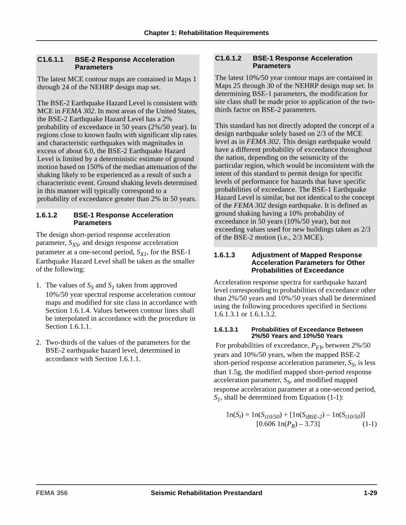
Chapter 1: Rehabilitation Requirements
1.6.1.2 BSE-1 Response Acceleration Parameters
The design short-period response acceleration parameter, SXS, and design response acceleration parameter at a one-second period, SX1, for the BSE-1 Earthquake Hazard Level shall be taken as the smaller of the following:
1. The values of SS and S1 taken from approved 10%/50 year spectral response acceleration contour maps and modified for site class in accordance with Section 1.6.1.4. Values between contour lines shall be interpolated in accordance with the procedure in Section 1.6.1.1.
2. Two-thirds of the values of the parameters for the BSE-2 earthquake hazard level, determined in accordance with Section 1.6.1.1.
1.6.1.3 Adjustment of Mapped Response Acceleration Parameters for Other Probabilities of Exceedance
Acceleration response spectra for earthquake hazard level corresponding to probabilities of exceedance other than 2%/50 years and 10%/50 years shall be determined using the following procedures specified in Sections 1.6.1.3.1 or 1.6.1.3.2.
1.6.1.3.1 Probabilities of Exceedance Between 2%/50 Years and 10%/50 Years
For probabilities of exceedance, PEY, between 2%/50 years and 10%/50 years, when the mapped BSE-2 short-period response acceleration parameter, SS, is less than 1.5g, the modified mapped short-period response acceleration parameter, SS, and modified mapped response acceleration parameter at a one-second period, S1, shall be determined from Equation (1-1):
1n(Si) = 1n(Si10/50) + [1n(SiBSE-2) – 1n(Si10/50)][0.606 1n(PR) – 3.73] (1-1)
C1.6.1.1 BSE-2 Response Acceleration Parameters
The latest MCE contour maps are contained in Maps 1 through 24 of the NEHRP design map set.
The BSE-2 Earthquake Hazard Level is consistent with MCE in FEMA 302. In most areas of the United States, the BSE-2 Earthquake Hazard Level has a 2% probability of exceedance in 50 years (2%/50 year). In regions close to known faults with significant slip rates and characteristic earthquakes with magnitudes in excess of about 6.0, the BSE-2 Earthquake Hazard Level is limited by a deterministic estimate of ground motion based on 150% of the median attenuation of the shaking likely to be experienced as a result of such a characteristic event. Ground shaking levels determined in this manner will typically correspond to a probability of exceedance greater than 2% in 50 years.
C1.6.1.2 BSE-1 Response Acceleration Parameters
The latest 10%/50 year contour maps are contained in Maps 25 through 30 of the NEHRP design map set. In determining BSE-1 parameters, the modification for site class shall be made prior to application of the two-thirds factor on BSE-2 parameters.
This standard has not directly adopted the concept of a design earthquake solely based on 2/3 of the MCE level as in FEMA 302. This design earthquake would have a different probability of exceedance throughout the nation, depending on the seismicity of the particular region, which would be inconsistent with the intent of this standard to permit design for specific levels of performance for hazards that have specific probabilities of exceedance. The BSE-1 Earthquake Hazard Level is similar, but not identical to the concept of the FEMA 302 design earthquake. It is defined as ground shaking having a 10% probability of exceedance in 50 years (10%/50 year), but not exceeding values used for new buildings taken as 2/3 of the BSE-2 motion (i.e., 2/3 MCE).
FEMA 356 Seismic Rehabilitation Prestandard 1-29
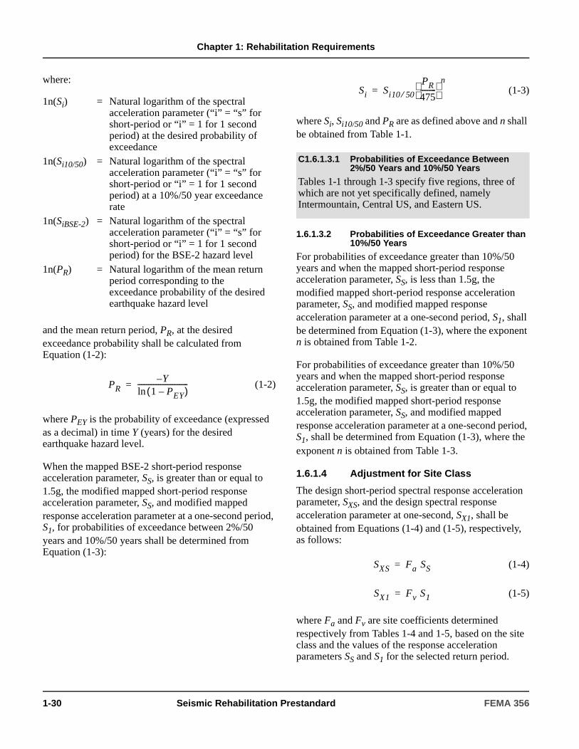
Chapter 1: Rehabilitation Requirements
where:
and the mean return period, PR, at the desired exceedance probability shall be calculated from Equation (1-2):
(1-2)
where PEY is the probability of exceedance (expressed as a decimal) in time Y (years) for the desired earthquake hazard level.
When the mapped BSE-2 short-period response acceleration parameter, SS, is greater than or equal to 1.5g, the modified mapped short-period response acceleration parameter, SS, and modified mapped response acceleration parameter at a one-second period, S1, for probabilities of exceedance between 2%/50 years and 10%/50 years shall be determined from Equation (1-3):
(1-3)
where Si, Si10/50 and PR are as defined above and n shall be obtained from Table 1-1.
1.6.1.3.2 Probabilities of Exceedance Greater than 10%/50 Years
For probabilities of exceedance greater than 10%/50 years and when the mapped short-period response acceleration parameter, SS, is less than 1.5g, the modified mapped short-period response acceleration parameter, SS, and modified mapped response acceleration parameter at a one-second period, S1, shall be determined from Equation (1-3), where the exponent n is obtained from Table 1-2.
For probabilities of exceedance greater than 10%/50 years and when the mapped short-period response acceleration parameter, SS, is greater than or equal to 1.5g, the modified mapped short-period response acceleration parameter, SS, and modified mapped response acceleration parameter at a one-second period, S1, shall be determined from Equation (1-3), where the exponent n is obtained from Table 1-3.
1.6.1.4 Adjustment for Site Class
The design short-period spectral response acceleration parameter, SXS, and the design spectral response acceleration parameter at one-second, SX1, shall be obtained from Equations (1-4) and (1-5), respectively, as follows:
(1-4)
(1-5)
where Fa and Fv are site coefficients determined respectively from Tables 1-4 and 1-5, based on the site class and the values of the response acceleration parameters SS and S1 for the selected return period.
1n(Si) = Natural logarithm of the spectral acceleration parameter (“i” = “s” for short-period or “i” = 1 for 1 second period) at the desired probability of exceedance
1n(Si10/50) = Natural logarithm of the spectral acceleration parameter (“i” = “s” for short-period or “i” = 1 for 1 second period) at a 10%/50 year exceedance rate
1n(SiBSE-2) = Natural logarithm of the spectral acceleration parameter (“i” = “s” for short-period or “i” = 1 for 1 second period) for the BSE-2 hazard level
1n(PR) = Natural logarithm of the mean return period corresponding to the exceedance probability of the desired earthquake hazard level
PRY–
1 PEY–( )ln-----------------------------=
C1.6.1.3.1 Probabilities of Exceedance Between 2%/50 Years and 10%/50 Years
Tables 1-1 through 1-3 specify five regions, three of which are not yet specifically defined, namely Intermountain, Central US, and Eastern US.
Si Si10 50⁄PR
475---------
n
=
SXS Fa SS=
SX1 Fv S1=
1-30 Seismic Rehabilitation Prestandard FEMA 356

Chapter 1: Rehabilitation Requirements
1.6.1.4.1 Site Classes
Site classes shall be defined as follows:
1. Class A: Hard rock with average shear wave
velocity, > 5,000 ft/sec
2. Class B: Rock with 2,500 ft/sec < < 5,000 ft/sec
3. Class C: Very dense soil and soft rock with
1,200 ft/sec < ≤ 2,500 ft/sec or with either
standard blow count > 50 or undrained shear
strength > 2,000 psf
4. Class D: Stiff soil with 600 ft/sec < ≤
1,200 ft/sec or with 15 < ≤ 50 or 1,000 psf ≤ < 2,000 psf
5. Class E: Any profile with more than 10 feet of soft clay defined as soil with plasticity index PI >
20, or water content w > 40 percent, and < 500
psf or a soil profile with < 600 ft/sec.
6. Class F: Soils requiring site-specific evaluations:
6.1. Soils vulnerable to potential failure or collapse under seismic loading, such as liquefiable soils, quick and highly-sensitive clays, collapsible weakly-cemented soils
6.2. Peats and/or highly organic clays (H > 10 feet of peat and/or highly organic clay, where H = thickness of soil)
6.3. Very high plasticity clays (H > 25 feet with PI > 75)
6.4. Very thick soft/medium stiff clays (H > 120 feet).
The parameters , , and are, respectively, the
average values of the shear wave velocity, Standard Penetration Test (SPT) blow count, and undrained shear strength of the upper 100 feet of soils at the site. These values shall be calculated from Equation (1-6), below:
(1-6)
where:
and
(1-7)
Where vs data are available for the site, such data shall be used to classify the site. If such data are not available, N data shall be used for cohesionless soil sites (sands, gravels), and su data for cohesive soil sites (clays). For rock in profile classes B and C, classification shall be based either on measured or estimated values of vs. Classification of a site as Class A rock shall be based on measurements of vs either for material at the site itself, or for rock having the same formation adjacent to the site; otherwise, Class B rock shall be assumed. Class A or B profiles shall not be assumed to be present if there is more than 10 feet of soil between the rock surface and the base of the building.
1.6.1.4.2 Default Site Class
If there is insufficient data available to classify a soil profile as Class A through C, and there is no evidence of soft clay soils characteristic of Class E in the vicinity of the site, the default site class shall be taken as Class D. If there is evidence of Class E soils in the vicinity of the site, and no other data supporting selection of Class A through D, the default site class shall be taken as Class E.
vs
vs
vs
N
su
vs
N su
su
vs
vs N su
Ni = SPT blow count in soil layer “i”
n = Number of layers of similar soil materials for which data is available
di = Depth of layer “i”
sui = Undrained shear strength in layer “i”
= Shear wave velocity of the soil in layer “i”
vs N su, ,
di
i 1=
n
∑
di
vsi------
di
Ni-----
di
sui------, ,
n
∑
-----------------------------------=
νsi
di
i 1=
n
∑ 100 ft=
FEMA 356 Seismic Rehabilitation Prestandard 1-31

Chapter 1: Rehabilitation Requirements
1.6.1.5 General Response Spectrum
A general response spectrum shall be developed as specified in Sections 1.6.1.5.1 through 1.6.1.5.3.
1.6.1.5.1 General Horizontal Response Spectrum
A general horizontal response spectrum as shown in Figure 1-1 shall be developed using Equations (1-8), (1-9), and (1-10) for spectral response acceleration, Sa, versus structural period, T, in the horizontal direction.
(1-8)
, and
, and (1-9)
(1-10)
where TS and T0 are given by Equations (1-11) and (1-12)
(1-11)
(1-12)
and where BS and B1 shall be taken from Table 1-6.
Use of spectral response accelerations calculated using Equation (1-8) in the extreme short period range (T < T0) shall only be permitted in dynamic analysis procedures and only for modes other than the fundamental mode.
1.6.1.5.2 General Vertical Response Spectrum
Where a vertical response spectrum is required, it shall be developed by taking two-thirds of the spectral ordinates, at each period, obtained for the horizontal response spectrum.
1.6.1.5.3 Damping Ratios
A 5% damped response spectrum shall be used for the rehabilitation design of all buildings and structural systems except those meeting the following criteria:
1. For structures without exterior cladding, an effective viscous damping ratio, β, equal to 2% of critical damping shall be assumed.
2. For structures with wood diaphragms and interior partitions and cross walls that interconnect the diaphragm levels at a maximum spacing of 40 feet on center transverse to the direction of motion, an effective viscous damping ratio, β, equal to 10% of critical damping shall be permitted.
3. For structures rehabilitated using seismic isolation technology or enhanced energy dissipation technology, an equivalent effective viscous damping ratio, β, shall be calculated using the procedures specified in Chapter 9.
Sa SXS5
BS------ 2–
TTS------ 0.4+=
for 0 T T0< <
Sa SXS BS⁄ for T TS<( )=
Sa SX1 B1T( )⁄( ) for T TS>=
TS SX1BS( ) SXSB1( )⁄=
T0 0.2TS=
Table 1-1 Values of Exponent n for Determination of Response Acceleration Parameters at Earthquake Hazard Levels between 10%/50 years and 2%/50 years;Sites where Mapped BSE-2 Values of SS ≥1.5g
Values of Exponent n for
Region SS S1
California 0.29 0.29
Pacific Northwest 0.56 0.67
Intermountain 0.50 0.60
Central US 0.98 1.09
Eastern US 0.93 1.05
1-32 Seismic Rehabilitation Prestandard FEMA 356
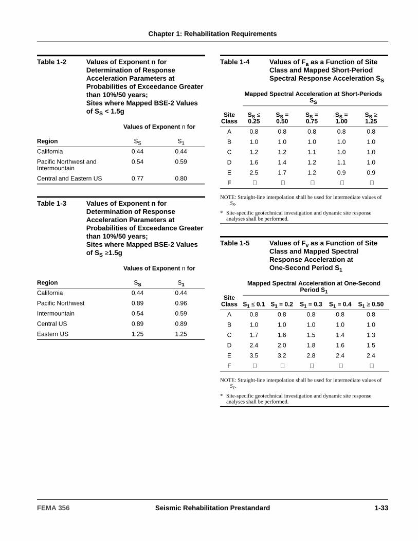
Chapter 1: Rehabilitation Requirements
Table 1-2 Values of Exponent n for Determination of Response Acceleration Parameters at Probabilities of Exceedance Greater than 10%/50 years;Sites where Mapped BSE-2 Values of SS < 1.5g
Values of Exponent n for
Region SS S1
California 0.44 0.44
Pacific Northwest and Intermountain
0.54 0.59
Central and Eastern US 0.77 0.80
Table 1-3 Values of Exponent n for Determination of Response Acceleration Parameters at Probabilities of Exceedance Greater than 10%/50 years;Sites where Mapped BSE-2 Values of SS ≥1.5g
Values of Exponent n for
Region SS S1
California 0.44 0.44
Pacific Northwest 0.89 0.96
Intermountain 0.54 0.59
Central US 0.89 0.89
Eastern US 1.25 1.25
Table 1-4 Values of Fa as a Function of Site Class and Mapped Short-Period Spectral Response Acceleration SS
Site Class
Mapped Spectral Acceleration at Short-Periods SS
SS ≤ 0.25
SS = 0.50
SS = 0.75
SS = 1.00
SS ≥ 1.25
A 0.8 0.8 0.8 0.8 0.8
B 1.0 1.0 1.0 1.0 1.0
C 1.2 1.2 1.1 1.0 1.0
D 1.6 1.4 1.2 1.1 1.0
E 2.5 1.7 1.2 0.9 0.9
F ∗ ∗ ∗ ∗ ∗
NOTE: Straight-line interpolation shall be used for intermediate values of SS.
* Site-specific geotechnical investigation and dynamic site response analyses shall be performed.
Table 1-5 Values of Fv as a Function of Site Class and Mapped Spectral Response Acceleration at One-Second Period S1
Site Class
Mapped Spectral Acceleration at One-Second Period S1
S1 ≤ 0.1 S1 = 0.2 S1 = 0.3 S1 = 0.4 S1 ≥ 0.50
A 0.8 0.8 0.8 0.8 0.8
B 1.0 1.0 1.0 1.0 1.0
C 1.7 1.6 1.5 1.4 1.3
D 2.4 2.0 1.8 1.6 1.5
E 3.5 3.2 2.8 2.4 2.4
F ∗ ∗ ∗ ∗ ∗
NOTE: Straight-line interpolation shall be used for intermediate values of S1.
* Site-specific geotechnical investigation and dynamic site response analyses shall be performed.
FEMA 356 Seismic Rehabilitation Prestandard 1-33

Chapter 1: Rehabilitation Requirements
1.6.2 Site-Specific Procedure for Hazard Due to Ground Shaking
Where site-specific ground shaking characterization is selected or required by the code official as the basis of rehabilitation design, the characterization shall be developed in accordance with this section.
1.6.2.1 Site-Specific Response Spectra
Development of site-specific response spectra shall be based on the geologic, seismologic, and soil characteristics associated with the specific site and as specified in Sections 1.6.2.1.1 through 1.6.2.1.4.
1.6.2.1.1 Damping Ratios
Response spectra shall be developed for an effective viscous damping ratio of 5% of critical damping and for other damping ratios appropriate to the indicated structural behavior, as discussed in Section 1.6.1.5.
1.6.2.1.2 Minimum Spectral Amplitude
The 5% damped site-specific spectral amplitudes in the period range of greatest significance to the structural response shall not be specified less than 70 percent of the spectral amplitudes of the General Response Spectrum.
1.6.2.1.3 Basis of the Response Spectra
Probabilistic site-specific spectra that represent the BSE-1 Earthquake Hazard Level shall be mean spectra at the 10%/50 year probability of exceedance. Probabilistic site-specific spectra that represent the BSE-2 Earthquake Hazard Level shall be mean spectra at the 2%/50 year probability of exceedance. Deterministic BSE-2 site-specific spectra shall be taken as 150% of the median spectra for the characteristic event on the controlling fault.
1.6.2.1.4 Site-Specific Response Acceleration Parameters and Construction of Response Spectra
The design response acceleration parameters, SXS, SX1, and TS shall be obtained using the site-specific response spectra in accordance with this section. Values of the design response acceleration parameter at short-periods, SXS, shall be taken as the response acceleration obtained from the site-specific spectra at a period of 0.2 seconds, except that it shall not be taken as less than 90% of the peak response acceleration at any period. In order to obtain values for the design spectral response acceleration parameter SX1, a curve of the form Sa = SX1/T shall be graphically overlaid on the site-specific spectra such that at any period, the value of Sa obtained from the curve is not less than 90% of that which would be obtained directly from the spectra. The value of TS shall be determined in accordance with Equation (1-13).
(1-13)
Table 1-6 Damping Coefficients BS and B1 as a Function of Effective Damping β
Effective Viscous Damping β (percentage of critical damping)1 BS B1
< 2 0.8 0.8
5 1.0 1.0
10 1.3 1.2
20 1.8 1.5
30 2.3 1.7
40 2.7 1.9
> 50 3.0 2.0
1. Damping coefficients shall be based on linear interpolation for effective viscous damping values other than those given.
Figure 1-1 General Horizontal Response Spectrum
TS SX1 SXS⁄=
1-34 Seismic Rehabilitation Prestandard FEMA 356
Chapter 1: Rehabilitation Requirements
1.6.2.1.5 Site-Specific BSE-2 Response Acceleration Parameters
The site-specific response acceleration parameters for the BSE-2 Earthquake Hazard Level shall be taken as the smaller of the following:
1. The values of the parameters from mean probabilistic site-specific spectra at the 2%/50 year probability of exceedance.
2. The values of the parameters from 150% of median deterministic site-specific spectra.
1.6.2.1.6 Site-Specific BSE-1 Response Acceleration Parameters
The site-specific response acceleration parameters for the BSE-1 Earthquake Hazard Level shall be taken as the smaller of the following:
1. The values of the parameters from mean probabilistic site-specific spectra at the 10%/50 year probability of exceedance.
2. Two-thirds of the values of the parameters determined for the BSE-2 Earthquake Hazard Level.
1.6.2.2 Acceleration Time Histories
Time history analysis shall be performed with no fewer than three data sets (each containing two horizontal components or, if vertical motion is to be considered, two horizontal components and one vertical component) of ground motion time histories that shall be selected and scaled from no fewer than three recorded events. Time histories shall have magnitude, fault distances, and source mechanisms that are equivalent to those that control the design earthquake ground motion. Where three recorded ground-motion time history data sets having these characteristics are not available, simulated time history data sets having equivalent duration and spectral content shall be used to make up the total number required. For each data set, the square root of the sum of the squares (SRSS) of the 5%-damped site-specific spectrum of the scaled horizontal components shall be constructed. The data sets shall be scaled such that the average value of the SRSS spectra does not fall below 1.4 times the 5%-damped spectrum for the design earthquake for periods between 0.2T seconds and 1.5T seconds (where T is the fundamental period of the building).
Where three time history data sets are used in the analysis of a structure, the maximum value of each response parameter (e.g., force in a member, displacement at a specific level) shall be used to determine design acceptability. Where seven or more time history data sets are employed, the average value of each response parameter shall be permitted to determine design acceptability.
1.6.3 Zones of Seismicity
The zone of seismicity shall be defined as High, Moderate, or Low as specified in Sections 1.6.3.1, 1.6.3.2, and 1.6.3.3, respectively.
1.6.3.1 Zones of High Seismicity
Buildings shall be considered to be located within zones of high seismicity where the 10%/50 year, design short-period response acceleration, SXS, and the 10%/50 year design one-second period response acceleration, SX1, are as specified in Equation (1-14):
SXS ≥ 0.5g andSX1 ≥ 0.2g (1-14)
C1.6.2.1 Procedure for Site-Specific Response Spectrum
The code official should consider an independent third-party review of the site-specific spectra by an individual with expertise in the evaluation of ground motion.
FEMA 356 Seismic Rehabilitation Prestandard 1-35

Chapter 1: Rehabilitation Requirements
1.6.3.2 Zones of Moderate Seismicity
Buildings shall be considered to be located within zones of moderate seismicity where the 10%/50 year, design short-period response acceleration, SXS, and the 10%/50 year, design one-second period response acceleration, SX1, are as specified in Equation (1-15):
0.167 ≤ SXS < 0.5g or0.067 ≤ SX1 < 0.2g (1-15)
1.6.3.3 Zones of Low Seismicity
Buildings shall be considered to be located within zones of low seismicity where the 10%/50 year, design short-period response acceleration, SXS, and the 10%/50 year, design one-second period response acceleration, SX1, are as specified in Equation (1-16):
SXS < 0.167g andSX1 < 0.067g (1-16)
1-36 Seismic Rehabilitation Prestandard FEMA 356
2. General Requirements
2.1 ScopeThis chapter sets forth general requirements for data collection, analysis procedures, methods, and strategies for the design of seismic rehabilitation projects.
Section 2.2 specifies data collection procedures for obtaining required as-built information on buildings. Section 2.3 outlines the Simplified and Systematic Methods for seismic rehabilitation of buildings. Section 2.4 specifies limitations on selecting analysis procedures, and defines component behavior types and corresponding acceptance criteria. Section 2.5 identifies acceptable rehabilitation strategies. Section 2.6 contains general design requirements for rehabilitation designs. Section 2.7 specifies construction quality assurance requirements. Section 2.8 specifies procedures for developing alternative modeling parameters and acceptance criteria.
2.2 As-Built InformationThe configuration of the structural system, as well as the type, detailing, connectivity, material strength and condition of the structural elements comprising the building shall be determined in accordance with this section. Data shall also be obtained for all nonstructural elements of the building that affect the forces and deformations experienced by the structural elements during response to earthquake ground motion. This data shall be obtained from available drawings, specifications, and other documents for the existing construction, and shall be supplemented and verified by on-site investigations including nondestructive examination and testing of building materials and components as required in Section 2.2.6.
At least one site visit shall be made to observe exposed conditions of building configuration, building components, site and foundation conditions, and adjacent structures, and to verify that as-built information obtained from other sources is representative of the existing conditions.
C2.2 As-Built InformationExisting building characteristics pertinent to seismic performance should be obtained from the following sources, as appropriate:
1. Field observation of exposed conditions and configuration.
2. Construction documents, engineering analyses, reports, soil borings and test logs, maintenance histories, and manufacturers’ literature and test data available from the owner and/or the code official.
3. Reference standards and codes from the period of construction as cited in Chapters 5 through 8.
4. Destructive and nondestructive examination and testing of selected building materials and components as specified in Section 2.2.6.
5. Interviews with building owners, tenants, managers, the original architect and engineer, contractor(s), and the local building official as arranged by the code official.
The information required for an existing building may also be available from a previously conducted seismic evaluation of the building. For situations where seismic rehabilitation has been mandated according to building construction classification, familiarity with the building type and typical seismic deficiencies is recommended. Such information is available from several sources, including FEMA 310. Such information may be sufficient for Simplified Rehabilitation. Additional as-built information may be needed for Systematic Rehabilitation.
When a destructive and nondestructive testing program is necessary to obtain as-built information, it is prudent to perform preliminary calculations to select key locations or parameters prior to establishing a detailed testing program. These obtain knowledge at a reasonable cost and with as little disruption as possible of construction features and materials properties at concealed locations.
FEMA 356 Seismic Rehabilitation Prestandard 2-1

Chapter 2: General Requirements
2.2.1 Building Configuration
The as-built building configuration information shall include data on the type and arrangement of existing structural elements and components of the gravity- and lateral-load-resisting systems, and the nonstructural components of the building that affect either the stiffness or strength of the structural elements, or the structural load path. The structural elements and components shall be identified and categorized as either primary or secondary, using the criteria described in Section 2.4.4.2.
The as-built building configuration shall be examined to identify the gravity and lateral load paths. These load paths shall be evaluated to identify seismic deficiencies prior to conducting a detailed rehabilitation design.
2.2.2 Component Properties
Sufficient as-built information shall be collected on component properties and their interconnection with other components to permit computation of strengths and deformation capacities. To account for any uncertainty associated with component as-built information, a knowledge factor κ shall be used in the capacity evaluation as specified in Section 2.2.6.4.
2.2.3 Site Characterization and Geotechnical Information
Data on foundation configuration and soil surface and subsurface conditions at the site shall be obtained from existing documentation, visual site reconnaissance, or a program of site-specific subsurface investigation in accordance with Chapter 4. A site-specific subsurface investigation shall be performed when Enhanced Rehabilitation Objectives are selected, or when insufficient data are available to quantify foundation capacities or determine the presence of geologic site hazards identified in Section 4.2.2. When historic information indicates geologic site hazards have occurred in the vicinity of the site, a site-specific subsurface investigation shall be performed to investigate the potential for geologic site hazards at the site. Use of applicable existing foundation capacity or geologic site hazard information available for the site shall be permitted.
If the building is a historic structure, it is also important to identify the locations of historically significant features and fabric which should be thoroughly investigated. Care should be taken in the design and investigation process to minimize the impact of work on these features. Refer to the Secretary of the Interior’s Standards for the Treatment of Historic Properties as discussed in Appendix A. The services of a historic preservation expert may be necessary.
C2.2.1 Building Configuration
Identifying the building configuration will identify both the intended load-resisting elements and effective load-resisting elements. Effective load-resisting elements may include structural elements and nonstructural elements that participate in resisting lateral loads, whether or not they were intended to do so by the original designers. Potential seismic deficiencies in intended and effective load resisting elements may include discontinuities in the load path, weak links, irregularities and inadequate strength and deformation capacities.
FEMA 310 is one example of a seismic evaluation tool that offers guidance on building configuration.
C2.2.2 Component Properties
Meaningful structural analysis of a building’s probable seismic behavior and reliable design of rehabilitation measures requires good understanding of the existing components (e.g., beams, columns, diaphragms), their interconnection, and their material properties (strength, deformability, and toughness). The strength and deformation capacity of existing components should be computed, as specified in Chapters 4 through 9 and 11, based on derived material properties and detailed component knowledge. Existing component action strengths must be determined for two basic purposes: to allow calculation of their ability to deliver load to other elements and components, and to allow determination of their capacity to resist forces and deformations.
2-2 Seismic Rehabilitation Prestandard FEMA 356
Chapter 2: General Requirements
A site reconnaissance shall be performed to observe variances from existing building drawings, foundation modifications not shown on existing documentation, the presence of adjacent development or grading activities, and evidence of poor foundation performance.
2.2.4 Adjacent Buildings
Sufficient data shall be collected on the configuration of adjacent structures to permit analysis of the interaction issues identified in Section 2.2.4.1 through 2.2.4.3. If the necessary information on adjacent structures is not available, the building owner shall be informed of the potential consequences of the interactions which are not being evaluated.
2.2.4.1 Building Pounding
Data shall be collected to permit investigation of the effects of building pounding in accordance with Section 2.6.10, whenever a portion of an adjacent structure is located within 4% of the height above grade at the location of potential impact.
2.2.4.2 Shared Element Condition
Data shall be collected on adjacent structures that share common vertical or lateral load-resisting elements with the building to permit investigation in accordance with Section 2.6.9.
2.2.4.3 Hazards from Adjacent Buildings
Data on adjacent buildings shall be collected to permit consideration of the potential for damage due to hazards such as falling debris, aggressive chemical leakage, fire, or explosion that might occur as a result of an earthquake. If the potential for such hazards exists, the building owner shall be notified of the potential impact on the ability to meet the selected Rehabilitation Objective.
C2.2.3 Site Characterization and Geotechnical Information
Sources of applicable existing geotechnical information include original design information, foundation capacity information included on the drawings, and previous geotechnical reports located at, or in the immediate vicinity, of the site.
Adjacent building development or grading activities that impose loads or reduce the lateral support of the structure can affect building performance in a future earthquake. Evidence of poor foundation performance can include settlement of building floor slabs and foundations, or differential movement visible at adjacent exterior sidewalks or other miscellaneous site construction.
C2.2.4.1 Building Pounding
Building pounding can alter the basic response of the building to ground motion and impart additional inertial loads and energy to the building from the adjacent structure. Of particular concern is the potential for extreme local damage to structural elements at the zones of impact.
C2.2.4.2 Shared Element Condition
Buildings sharing common elements, such as party walls, have several potential problems. If the buildings attempt to move independently, one building may pull the shared element away from the other, resulting in a partial collapse. If the buildings behave as an integral unit, the additional mass and inertial loads of one structure may result in extreme demands on the lateral-force-resisting system of the other.
C2.2.4.3 Hazards from Adjacent Buildings
Hazards from adjacent buildings that may impact building performance or the operation of the building after an earthquake should be considered and discussed with the building owner. Consideration should be given to hardening those portions of the building that may be impacted by debris or other hazards from adjacent structures. Where Immediate Occupancy of the building is desired and ingress to the building may be impaired by such hazards, consideration should be given to providing suitably resistant access to the building. Sufficient information should be collected on adjacent structures to allow preliminary evaluation of the likelihood and nature of hazards such as potential falling debris, fire, and blast pressures. Evaluations similar to those in FEMA 154 may be adequate for this purpose.
FEMA 356 Seismic Rehabilitation Prestandard 2-3
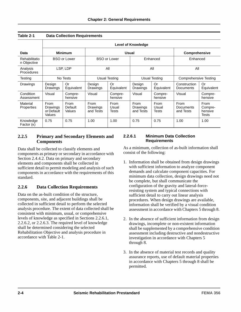
Chapter 2: General Requirements
2.2.5 Primary and Secondary Elements and Components
Data shall be collected to classify elements and components as primary or secondary in accordance with Section 2.4.4.2. Data on primary and secondary elements and components shall be collected in sufficient detail to permit modeling and analysis of such components in accordance with the requirements of this standard.
2.2.6 Data Collection Requirements
Data on the as-built condition of the structure, components, site, and adjacent buildings shall be collected in sufficient detail to perform the selected analysis procedure. The extent of data collected shall be consistent with minimum, usual, or comprehensive levels of knowledge as specified in Sections 2.2.6.1, 2.2.6.2, or 2.2.6.3. The required level of knowledge shall be determined considering the selected Rehabilitation Objective and analysis procedure in accordance with Table 2-1.
2.2.6.1 Minimum Data Collection Requirements
As a minimum, collection of as-built information shall consist of the following:
1. Information shall be obtained from design drawings with sufficient information to analyze component demands and calculate component capacities. For minimum data collection, design drawings need not be complete, but shall communicate the configuration of the gravity and lateral-force-resisting system and typical connections with sufficient detail to carry out linear analysis procedures. When design drawings are available, information shall be verified by a visual condition assessment in accordance with Chapters 5 through 8.
2. In the absence of sufficient information from design drawings, incomplete or non-existent information shall be supplemented by a comprehensive condition assessment including destructive and nondestructive investigation in accordance with Chapters 5 through 8.
3. In the absence of material test records and quality assurance reports, use of default material properties in accordance with Chapters 5 through 8 shall be permitted.
Table 2-1 Data Collection Requirements
Data
Level of Knowledge
Minimum Usual Comprehensive
Rehabilitation Objective
BSO or Lower BSO or Lower Enhanced Enhanced
Analysis Procedures
LSP, LDP All All All
Testing No Tests Usual Testing Usual Testing Comprehensive Testing
Drawings DesignDrawings
OrEquivalent
DesignDrawings
OrEquivalent
DesignDrawings
OrEquivalent
Construction Documents
Or Equivalent
Condition Assessment
Visual Compre-hensive
Visual Compre-hensive
Visual Compre-hensive
Visual Compre-hensive
Material Properties
From Drawings or Default Values
From Default Values
From Drawings and Tests
From Usual Tests
From Drawings and Tests
From Usual Tests
From Documents and Tests
From Compre-hensive Tests
Knowledge Factor (κ)
0.75 0.75 1.00 1.00 0.75 0.75 1.00 1.00
2-4 Seismic Rehabilitation Prestandard FEMA 356

Chapter 2: General Requirements
4. Information needed on adjacent buildings, referenced in Section 2.2.4, shall be gained through field surveys and research of available as-built information.
5. Information on foundation and site related concerns shall be collected in accordance with Section 2.2.3.
2.2.6.2 Usual Data Collection Requirements
Usual collection of as-built information shall consist of the following:
1. Information shall be obtained from design drawings with sufficient information to analyze component demands and calculate component capacities. For usual data collection, design drawings need not be complete, but shall communicate the configuration of the gravity and lateral-force-resisting system and typical connections with sufficient detail to carry out any analysis procedure. When design drawings are available, information shall be verified by a visual condition assessment in accordance with Chapters 5 through 8.
2. In the absence of sufficient information from design drawings, incomplete or non-existent information shall be supplemented by a comprehensive condition assessment including destructive and nondestructive investigation in accordance with Chapters 5 through 8.
3. In the absence of material test records and quality assurance reports, material properties shall be determined by usual materials testing in accordance with Chapters 5 through 8.
4. Information needed on adjacent buildings, referenced in Section 2.2.4, shall be gained through field surveys and research of available as-built information.
5. Information on foundation and site related concerns shall be collected in accordance with Section 2.2.3.
2.2.6.3 Comprehensive Data Collection Requirements
Comprehensive collection of as-built information shall consist of the following:
1. Information shall be obtained from construction documents including design drawings, specifications, material test records, and quality assurance reports covering original construction and subsequent modifications to the structure. When construction documents are available, information shall be verified by a visual condition assessment in accordance with Chapters 5 through 8.
2. If construction documents are incomplete, missing information shall be supplemented by a comprehensive condition assessment including destructive and nondestructive investigation in accordance with Chapters 5 through 8.
3. In the absence of material test records and quality assurance reports, material properties shall be determined by comprehensive materials testing in accordance with Chapters 5 through 8. The coefficient of variation in material test results shall be less than 20%.
4. Information needed on adjacent buildings, referenced in Section 2.2.4, shall be gained through field surveys and research of available as-built information.
5. Information on foundation and site related concerns shall be collected in accordance with Section 2.2.3.
FEMA 356 Seismic Rehabilitation Prestandard 2-5

Chapter 2: General Requirements
2.2.6.4 Knowledge Factor
2.2.6.4.1 General
To account for uncertainty in the collection of as-built data, a knowledge factor, κ, shall be selected from Table 2-1 considering the selected Rehabilitation Objective, analysis procedure, and data collection process. Knowledge factors shall be applied on a component basis as determined by the level of knowledge obtained for individual components during data collection.
2.2.6.4.2 Linear Procedures
When linear procedures are used, data collection consistent with the minimum level of knowledge shall be permitted.
2.2.6.4.3 Nonlinear Procedures
When nonlinear procedures are used, data collection consistent with either the usual or comprehensive levels of knowledge shall be performed.
2.2.6.4.4 Assumed values of Knowledge Factor
Selected κ values shall be supported by data collection performed at any time prior to implementation of a rehabilitation strategy. It shall be permitted to perform an analysis in advance of the data collection process using an assumed value of κ, provided the value of κ is substantiated by data collection in accordance with the requirements of Section 2.2.6 prior to implementation of the rehabilitation strategies.
If the assumed value of κ is not supported by subsequent data collection, the analysis shall be revised to include a revised κ consistent with the data collected in accordance with the requirements of Section 2.2.6.
If an analysis using an assumed value of κ will result in no required rehabilitation of the structure, the value of κ shall be substantiated by data collection in accordance with the requirements of Section 2.2.6 before the analysis is finalized.
2.3 Rehabilitation MethodsSeismic rehabilitation of the building shall be performed to achieve the selected Rehabilitation Objective in accordance with the requirements of the Simplified Rehabilitation Method of Section 2.3.1 or the Systematic Rehabilitation Method of Section 2.3.2.
2.3.1 Simplified Rehabilitation Method
The Simplified Rehabilitation Method shall be permitted for buildings that conform to one of the Model Building Types contained in Table 10-1, and all limitations in that table with regard to building size and seismic zone.
Use of the Simplified Rehabilitation Method shall be restricted to Limited Rehabilitation Objectives consisting of the Life Safety Building Performance Level (3-C) at the BSE-1 Earthquake Hazard Level, or Partial Rehabilitation as defined in Section 1.4.3.2.
The Simplified Rehabilitation Method shall be performed in accordance with the requirements of Chapters 2, 10, and 11.
C2.2.6.4.1 General
The κ factor is used to express the confidence with which the properties of the building components are known, when calculating component capacities. The value of the factor is established from the knowledge obtained based on access to original construction documents, or condition assessments including destructive or nondestructive testing of representative components. The values of the factor have been established, indicating whether the level of knowledge is “minimum,” “usual,” or “comprehensive.”
C2.3.1 Simplified Rehabilitation Method
Simplified Rehabilitation may be applied to certain buildings of regular configuration that do not require advanced analytical procedures. The primary intent of Simplified Rehabilitation is to reduce seismic risk efficiently, where possible and appropriate, by seeking Limited Objectives. Partial Rehabilitation measures, which target high-risk building deficiencies such as parapets and other exterior falling hazards, are included as Simplified Rehabilitation techniques.
The Simplified Rehabilitation Method is less complicated than the complete analytical rehabilitation design procedures found under Systematic Rehabilitation. In many cases, Simplified Rehabilitation represents a cost-effective improvement in seismic performance, and often requires less detailed evaluation or partial analysis to qualify for a specific performance level.
2-6 Seismic Rehabilitation Prestandard FEMA 356

Chapter 2: General Requirements
2.3.2 Systematic Rehabilitation Method
If the Simplified Rehabilitation Method is not applicable, the Systematic Rehabilitation Method shall be used as specified below:
1. An analysis procedure shall be selected in accordance with the requirements and limitations of Section 2.4.
2. A preliminary rehabilitation scheme shall be developed using one or more of the rehabilitation strategies defined in Section 2.5.
3. An analysis of the building, including rehabilitation measures, shall be performed, and the results of the analysis shall be evaluated in accordance with the requirements of Chapters 2 through 9 and 11 to verify the rehabilitation design meets the selected Rehabilitation Objective.
C2.3.2 Systematic Rehabilitation Method
Systematic Rehabilitation may be applied to any building and involves thorough checking of each existing structural element or component, the design of new ones, and verification of acceptable overall performance represented by expected displacements and internal forces. The Systematic Rehabilitation Method focuses on the nonlinear behavior of structural response, and employs procedures not previously emphasized in seismic codes.
The Systematic Rehabilitation Method is intended to be complete and contains all requirements to reach any specified performance level. Systematic Rehabilitation is an iterative process, similar to the design of new buildings, in which modifications of the existing structure are assumed for the purposes of a preliminary design and analysis, and the results of the analysis are verified as acceptable on an element and component basis. If either new or existing components or elements still prove to be inadequate, the modifications are adjusted and, if necessary, a new analysis and verification cycle is performed. A preliminary design is needed to define the extent and configuration of corrective measures in sufficient detail to estimate the interaction of the stiffness, strength, and post-yield behavior of all new, modified, or existing elements to be used for lateral force resistance. The designer is encouraged to include all elements with significant lateral stiffness in a mathematical model to assure deformation capability under realistic seismic drifts. However, just as in the design of new buildings, it may be determined that certain components or elements will not be considered part of the lateral-force-resisting system, as long as deformation compatibility checks are made on these components or elements to assure their adequacy.
A mathematical model, developed for the preliminary design, must be constructed in connection with one of the analysis procedures defined in Chapter 3. These are the linear procedures (Linear Static and Linear Dynamic) and the nonlinear procedures (Nonlinear Static and Nonlinear Dynamic). With the exception of the Nonlinear Dynamic Procedure, this standard defines the analysis and rehabilitation design procedures sufficiently that compliance can be checked by a building department in a manner similar to design reviews for new buildings. Modeling assumptions to be used in various situations are given in Chapters 4 through 9, and in Chapter 11 for nonstructural components. Requirements for seismic demand are given in Chapter 1. Requirements are specified for use of the Nonlinear Dynamic Procedure; however, considerable judgment is required in its application. Criteria for applying ground motion for various analysis procedures is given, but definitive rules for developing ground motion input are not included in this standard.
FEMA 356 Seismic Rehabilitation Prestandard 2-7

Chapter 2: General Requirements
2.4 Analysis ProceduresAn analysis of the building, including rehabilitation measures, shall be conducted to determine the forces and deformations induced in components of the building by ground motion corresponding to the selected Earthquake Hazard Level, or by other seismic geologic site hazards specified in Section 4.2.2.
The analysis procedure shall comply with one of the following:
1. Linear analysis subject to limitations specified in Section 2.4.1, and complying with the Linear Static Procedure (LSP) in accordance with Section 3.3.1, or the Linear Dynamic Procedure (LDP) in accordance with Section 3.3.2.
2. Nonlinear analysis subject to limitations specified in Section 2.4.2, and complying with the Nonlinear Static Procedure (NSP) in accordance with Section 3.3.3, or the Nonlinear Dynamic Procedure (NDP) in accordance with Section 3.3.4.
3. Alternative rational analysis in accordance with Section 2.4.3.
The analysis results shall comply with the applicable acceptance criteria selected in accordance with Section 2.4.4.
This standard specifies acceptance criteria for stiffness, strength, and ductility characteristics of structural elements and components for three discrete structural performance levels in Chapters 4 though 8 for use in the Systematic Rehabilitation Method, and acceptance criteria for the performance of nonstructural components or architectural, mechanical, and electrical components in Chapter 11 for use in Systematic and Simplified Rehabilitation Methods.
Inherent in the concept of performance levels and ranges is the assumption that performance can be measured using analytical results such as story drift ratios or strength and ductility demands on individual components or elements. To enable structural verification at the selected performance level, stiffness, strength, and ductility characteristics of many common elements and components have been derived from laboratory tests and analytical studies and are presented in a standard format in Chapters 4 through 8 of this standard.
This standard specifies two new technologies in Chapter 9: seismic isolation and energy dissipation, for use in seismic rehabilitation of buildings using the Systematic Rehabilitation Method.
It is expected that testing of existing materials and elements will continue and that additional corrective measures and products will be developed. It is also expected that systems and products intended to modify structural response beneficially will be advanced. The format of the analysis techniques and acceptability criteria of this standard allows rapid incorporation of such technology. Section 2.8 gives specific requirements in this regard. It is expected that this standard will have a significant impact on testing and documentation of existing materials and systems as well as on new products.
C2.4 Analysis ProceduresThe linear procedures maintain the traditional use of a linear stress-strain relationship, but incorporate adjustments to overall building deformations and material acceptance criteria to permit better consideration of the probable nonlinear characteristics of seismic response. The Nonlinear Static Procedure, often called “pushover analysis,” uses simplified nonlinear techniques to estimate seismic structural deformations. The Nonlinear Dynamic Procedure, commonly known as nonlinear time history analysis, requires considerable judgment and experience to perform, and may be used only within the limitations described in Section 2.4.2.2 of this standard.
2-8 Seismic Rehabilitation Prestandard FEMA 356
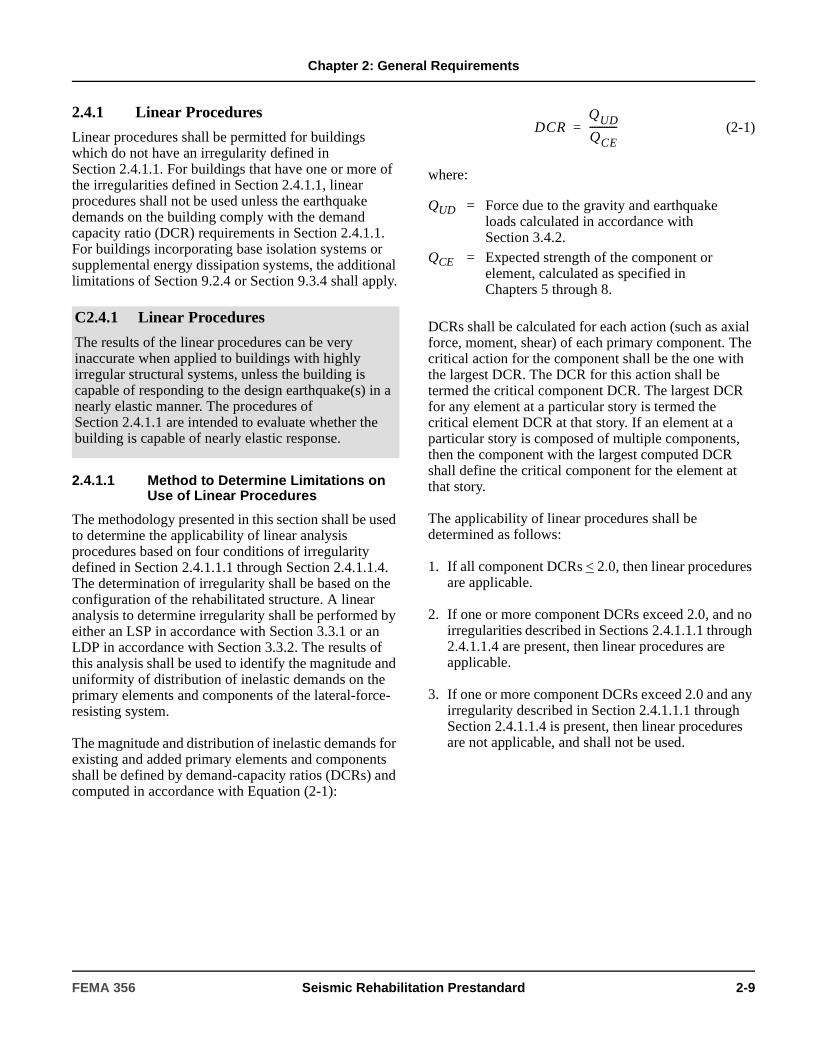
Chapter 2: General Requirements
2.4.1 Linear Procedures
Linear procedures shall be permitted for buildings which do not have an irregularity defined in Section 2.4.1.1. For buildings that have one or more of the irregularities defined in Section 2.4.1.1, linear procedures shall not be used unless the earthquake demands on the building comply with the demand capacity ratio (DCR) requirements in Section 2.4.1.1. For buildings incorporating base isolation systems or supplemental energy dissipation systems, the additional limitations of Section 9.2.4 or Section 9.3.4 shall apply.
2.4.1.1 Method to Determine Limitations on Use of Linear Procedures
The methodology presented in this section shall be used to determine the applicability of linear analysis procedures based on four conditions of irregularity defined in Section 2.4.1.1.1 through Section 2.4.1.1.4. The determination of irregularity shall be based on the configuration of the rehabilitated structure. A linear analysis to determine irregularity shall be performed by either an LSP in accordance with Section 3.3.1 or an LDP in accordance with Section 3.3.2. The results of this analysis shall be used to identify the magnitude and uniformity of distribution of inelastic demands on the primary elements and components of the lateral-force-resisting system.
The magnitude and distribution of inelastic demands for existing and added primary elements and components shall be defined by demand-capacity ratios (DCRs) and computed in accordance with Equation (2-1):
(2-1)
where:
DCRs shall be calculated for each action (such as axial force, moment, shear) of each primary component. The critical action for the component shall be the one with the largest DCR. The DCR for this action shall be termed the critical component DCR. The largest DCR for any element at a particular story is termed the critical element DCR at that story. If an element at a particular story is composed of multiple components, then the component with the largest computed DCR shall define the critical component for the element at that story.
The applicability of linear procedures shall be determined as follows:
1. If all component DCRs < 2.0, then linear procedures are applicable.
2. If one or more component DCRs exceed 2.0, and no irregularities described in Sections 2.4.1.1.1 through 2.4.1.1.4 are present, then linear procedures are applicable.
3. If one or more component DCRs exceed 2.0 and any irregularity described in Section 2.4.1.1.1 through Section 2.4.1.1.4 is present, then linear procedures are not applicable, and shall not be used.
C2.4.1 Linear Procedures
The results of the linear procedures can be very inaccurate when applied to buildings with highly irregular structural systems, unless the building is capable of responding to the design earthquake(s) in a nearly elastic manner. The procedures of Section 2.4.1.1 are intended to evaluate whether the building is capable of nearly elastic response.
QUD = Force due to the gravity and earthquake loads calculated in accordance with Section 3.4.2.
QCE = Expected strength of the component or element, calculated as specified in Chapters 5 through 8.
DCRQUD
QCE-----------=
FEMA 356 Seismic Rehabilitation Prestandard 2-9
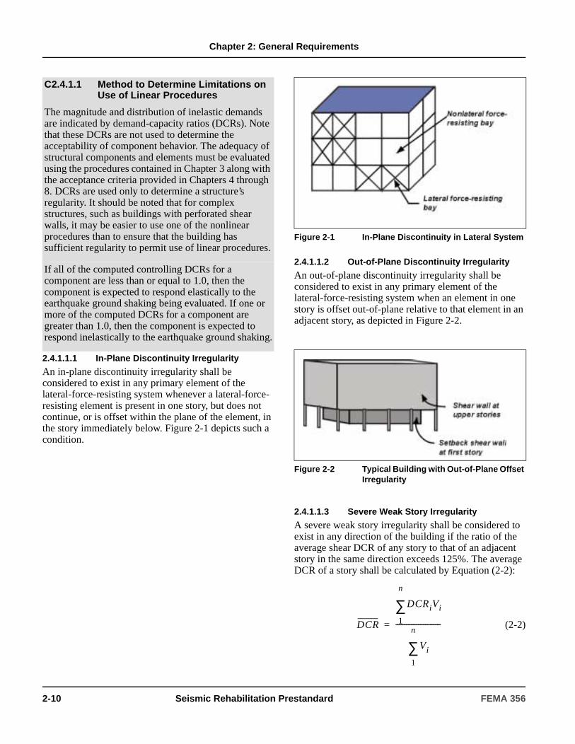
Chapter 2: General Requirements
2.4.1.1.1 In-Plane Discontinuity Irregularity
An in-plane discontinuity irregularity shall be considered to exist in any primary element of the lateral-force-resisting system whenever a lateral-force-resisting element is present in one story, but does not continue, or is offset within the plane of the element, in the story immediately below. Figure 2-1 depicts such a condition.
2.4.1.1.2 Out-of-Plane Discontinuity Irregularity
An out-of-plane discontinuity irregularity shall be considered to exist in any primary element of the lateral-force-resisting system when an element in one story is offset out-of-plane relative to that element in an adjacent story, as depicted in Figure 2-2.
2.4.1.1.3 Severe Weak Story Irregularity
A severe weak story irregularity shall be considered to exist in any direction of the building if the ratio of the average shear DCR of any story to that of an adjacent story in the same direction exceeds 125%. The average DCR of a story shall be calculated by Equation (2-2):
(2-2)
C2.4.1.1 Method to Determine Limitations on Use of Linear Procedures
The magnitude and distribution of inelastic demands are indicated by demand-capacity ratios (DCRs). Note that these DCRs are not used to determine the acceptability of component behavior. The adequacy of structural components and elements must be evaluated using the procedures contained in Chapter 3 along with the acceptance criteria provided in Chapters 4 through 8. DCRs are used only to determine a structure’s regularity. It should be noted that for complex structures, such as buildings with perforated shear walls, it may be easier to use one of the nonlinear procedures than to ensure that the building has sufficient regularity to permit use of linear procedures.
If all of the computed controlling DCRs for a component are less than or equal to 1.0, then the component is expected to respond elastically to the earthquake ground shaking being evaluated. If one or more of the computed DCRs for a component are greater than 1.0, then the component is expected to respond inelastically to the earthquake ground shaking.
Figure 2-1 In-Plane Discontinuity in Lateral System
Figure 2-2 Typical Building with Out-of-Plane Offset Irregularity
DCR
DCRiVi
1
n
∑
Vi
1
n
∑
--------------------------=
2-10 Seismic Rehabilitation Prestandard FEMA 356

Chapter 2: General Requirements
where:
For buildings with flexible diaphragms, each line of framing shall be independently evaluated.
2.4.1.1.4 Severe Torsional Strength Irregularity
A severe torsional strength irregularity shall be considered to exist in any story if the diaphragm above the story under consideration is not flexible and, for a given direction, the ratio of the critical element DCRs for primary elements on one side of the center of resistance of a story, to those on the other side of the center of resistance of the story, exceeds 1.5.
2.4.1.2 Limitations on Use of the Linear Static Procedure
The Linear Static Procedure shall not be used for a building with one or more of the following characteristics:
1. The fundamental period of the building, T, is greater than or equal to 3.5 times Ts.
2. The ratio of the horizontal dimension at any story to the corresponding dimension at an adjacent story exceeds 1.4 (excluding penthouses).
3. The building has a severe torsional stiffness irregularity in any story. A severe torsional stiffness irregularity exists in a story if the diaphragm above the story under consideration is not flexible and the results of the analysis indicate that the drift along any side of the structure is more than 150% of the average story drift.
4. The building has a severe vertical mass or stiffness irregularity. A severe vertical mass or stiffness irregularity exists when the average drift in any story (except penthouses) exceeds that of the story above or below by more than 150%.
5. The building has a nonorthogonal lateral-force- resisting system.
For buildings in which linear procedures are applicable, but the Linear Static Procedure is not permitted, use of the Linear Dynamic Procedure shall be permitted.
2.4.2 Nonlinear Procedures
Nonlinear procedures shall be permitted for any of the rehabilitation strategies contained in Section 2.5. Nonlinear procedures shall be used for analysis of buildings when linear procedures are not permitted. Data collection for use with nonlinear procedures shall be in accordance with Section 2.2.6.
2.4.2.1 Nonlinear Static Procedure
The NSP shall be permitted for structures in which higher mode effects are not significant, as defined in this section. To determine if higher modes are significant, a modal response spectrum analysis shall be performed for the structure using sufficient modes to capture 90% mass participation. A second response spectrum analysis shall also be performed, considering only the first mode participation. Higher mode effects shall be considered significant if the shear in any story resulting from the modal analysis considering modes required to obtain 90% mass participation exceeds 130% of the corresponding story shear considering only the first mode response.
DCR = Average DCR for the storyDCRi = Critical action DCR for element i of the
storyVi = Total calculated lateral shear force in an
element i due to earthquake response, assuming that the structure remains elastic
n = Total number of elements in the story
C2.4.1.2 Limitations on Use of the Linear Static Procedure
For buildings that have irregular distributions of mass or stiffness, irregular geometries, or nonorthogonal lateral-force-resisting systems, the distribution of demands predicted by an LDP analysis will be more accurate than those predicted by the LSP. Either the response spectrum method or time history method may be used for evaluation of such structures.
FEMA 356 Seismic Rehabilitation Prestandard 2-11

Chapter 2: General Requirements
If higher mode effects are significant, the NSP shall be permitted if an LDP analysis is also performed to supplement the NSP. Buildings with significant higher mode effects must meet the acceptance criteria of this standard for both analysis procedures, except that an increase by a factor of 1.33 shall be permitted in the LDP acceptance criteria for deformation-controlled actions (m-factors) provided in Chapters 5 through 9. A building analyzed using the NSP, with or without a supplementary LDP evaluation, shall meet the acceptance criteria for nonlinear procedures specified in Section 3.4.3.
2.4.2.2 Nonlinear Dynamic Procedure
The NDP shall be permitted for all structures. An analysis performed using the NDP shall be reviewed and approved by an independent third-party engineer with experience in seismic design and nonlinear procedures.
2.4.3 Alternative Rational Analysis
Nothing in this standard shall be interpreted as preventing the use of any approved alternative analysis procedure that is rational and based on fundamental principles of engineering mechanics and dynamics. Such alternative analyses shall not adopt the acceptance criteria contained in this standard without first determining their applicability. All projects using alternative rational analysis procedures shall be reviewed and approved by an independent third-party engineer with experience in seismic design.
2.4.4 Acceptance Criteria
2.4.4.1 General
The acceptability of force and deformation actions shall be evaluated for each component in accordance with the requirements of Section 3.4. Prior to selecting component acceptance criteria for use in Section 3.4, each component shall be classified as primary or secondary in accordance with Section 2.4.4.2, and each action shall be classified as deformation-controlled (ductile) or force-controlled (nonductile) in accordance with Section 2.4.4.3. Component strengths, material properties, and component capacities shall be determined in accordance with Sections 2.4.4.4, 2.4.4.5, and 2.4.4.6, respectively. Component acceptance criteria not presented in this standard shall be determined by qualification testing in accordance with Section 2.8.
The rehabilitated building shall be provided with at least one continuous load path to transfer seismic forces, induced by ground motion in any direction, from the point of application to the final point of resistance. All primary and secondary components shall be capable of resisting force and deformation actions within the applicable acceptance criteria of the selected performance level.
2.4.4.2 Primary and Secondary Elements and Components
Elements and components that affect the lateral stiffness or distribution of forces in a structure, or are loaded as a result of lateral deformation of the structure, shall be classified as primary or secondary, even if they are not part of the intended lateral-force-resisting system.
2.4.4.2.1 Primary Elements and Components
Elements and components that provide the capacity of the structure to resist collapse under seismic forces induced by ground motion in any direction shall be classified as primary.
C2.4.2.1 Nonlinear Static Procedure
The NSP is generally a more reliable approach to characterizing the performance of a structure than are linear procedures. However, it is not exact, and cannot accurately account for changes in dynamic response as the structure degrades in stiffness or account for higher mode effects. When the NSP is utilized on a structure that has significant higher mode response, the LDP is also employed to verify the adequacy of the design. When this approach is taken, less restrictive criteria are permitted for the LDP, recognizing the significantly improved knowledge that is obtained by performing both analysis procedures.
2-12 Seismic Rehabilitation Prestandard FEMA 356

Chapter 2: General Requirements
2.4.4.2.2 Secondary Elements and Components
Other elements and components shall be classified as secondary.
2.4.4.3 Deformation- and Force-Controlled Actions
All actions shall be classified as either deformation-controlled or force-controlled using the component force versus deformation curves shown in Figure 2-3.
Figure 2-3 Component Force Versus Deformation Curves
C2.4.4.2 Primary and Secondary Elements and Components
In a typical building, nearly all elements, including many nonstructural components, will contribute to the building’s overall stiffness, mass, and damping, and consequently its response to earthquake ground motion. However, not all of these elements are critical to the ability of the structure to resist collapse when subjected to strong ground shaking.
The secondary designation typically will be used when a component or element does not contribute significantly or reliably in resisting earthquake effects because of low lateral stiffness, strength, or deformation capacity.
For example, exterior cladding and interior partitions can add substantial initial stiffness to a structure, yet this stiffness is not typically considered in the design of new buildings because the lateral strength of these elements is often small. Similarly, the interaction of floor framing systems and columns in shear wall buildings can add some stiffness, although designers typically neglect such stiffness when proportioning the building’s shear walls.
The concept of primary and secondary elements permits the engineer to differentiate between the performance required of elements that are critical to the building’s ability to resist collapse and of those that are not. For a given performance level, acceptance criteria for primary elements and components will typically be more restrictive than those for secondary elements and components.
Use of the secondary classification will allow certain components to experience greater damage and larger displacements than would otherwise be permitted for primary elements, as explained below.
1. Although damage to the primary elements and some degradation of their stiffness may be permitted to occur, the overall function of these elements in resisting structural collapse should not be compromised.
2. For some structural performance levels, substantial degradation of the lateral-force-resisting stiffness and strength of secondary elements and components is permissible. However, the ability of these secondary elements and components to support gravity loads under the maximum induced deformations must be preserved.
FEMA 356 Seismic Rehabilitation Prestandard 2-13
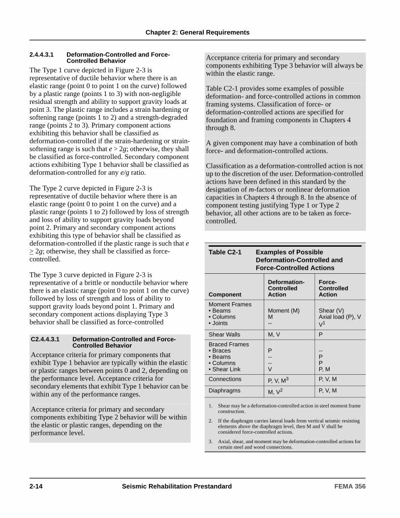
Chapter 2: General Requirements
2.4.4.3.1 Deformation-Controlled and Force-Controlled Behavior
The Type 1 curve depicted in Figure 2-3 is representative of ductile behavior where there is an elastic range (point 0 to point 1 on the curve) followed by a plastic range (points 1 to 3) with non-negligible residual strength and ability to support gravity loads at point 3. The plastic range includes a strain hardening or softening range (points 1 to 2) and a strength-degraded range (points 2 to 3). Primary component actions exhibiting this behavior shall be classified as deformation-controlled if the strain-hardening or strain-softening range is such that e > 2g; otherwise, they shall be classified as force-controlled. Secondary component actions exhibiting Type 1 behavior shall be classified as deformation-controlled for any e/g ratio.
The Type 2 curve depicted in Figure 2-3 is representative of ductile behavior where there is an elastic range (point 0 to point 1 on the curve) and a plastic range (points 1 to 2) followed by loss of strength and loss of ability to support gravity loads beyond point 2. Primary and secondary component actions exhibiting this type of behavior shall be classified as deformation-controlled if the plastic range is such that e > 2g; otherwise, they shall be classified as force-controlled.
The Type 3 curve depicted in Figure 2-3 is representative of a brittle or nonductile behavior where there is an elastic range (point 0 to point 1 on the curve) followed by loss of strength and loss of ability to support gravity loads beyond point 1. Primary and secondary component actions displaying Type 3 behavior shall be classified as force-controlled
C2.4.4.3.1 Deformation-Controlled and Force-Controlled Behavior
Acceptance criteria for primary components that exhibit Type 1 behavior are typically within the elastic or plastic ranges between points 0 and 2, depending on the performance level. Acceptance criteria for secondary elements that exhibit Type 1 behavior can be within any of the performance ranges.
Acceptance criteria for primary and secondary components exhibiting Type 2 behavior will be within the elastic or plastic ranges, depending on the performance level.
Acceptance criteria for primary and secondary components exhibiting Type 3 behavior will always be within the elastic range.
Table C2-1 provides some examples of possible deformation- and force-controlled actions in common framing systems. Classification of force- or deformation-controlled actions are specified for foundation and framing components in Chapters 4 through 8.
A given component may have a combination of both force- and deformation-controlled actions.
Classification as a deformation-controlled action is not up to the discretion of the user. Deformation-controlled actions have been defined in this standard by the designation of m-factors or nonlinear deformation capacities in Chapters 4 through 8. In the absence of component testing justifying Type 1 or Type 2 behavior, all other actions are to be taken as force-controlled.
Table C2-1 Examples of Possible Deformation-Controlled and Force-Controlled Actions
Component
Deformation- Controlled Action
Force- Controlled Action
Moment Frames• Beams• Columns• Joints
Moment (M)M--
Shear (V)Axial load (P), VV1
Shear Walls M, V P
Braced Frames• Braces• Beams• Columns• Shear Link
P----V
--PPP, M
Connections P, V, M3 P, V, M
Diaphragms M, V2 P, V, M
1. Shear may be a deformation-controlled action in steel moment frame construction.
2. If the diaphragm carries lateral loads from vertical seismic resisting elements above the diaphragm level, then M and V shall be considered force-controlled actions.
3. Axial, shear, and moment may be deformation-controlled actions for certain steel and wood connections.
2-14 Seismic Rehabilitation Prestandard FEMA 356

Chapter 2: General Requirements
Figure C2-1 shows the generalized force versus deformation curves used throughout this standard to specify component modeling and acceptance criteria for deformation-controlled actions in any of the four basic material types. Linear response is depicted between point A (unloaded component) and an effective yield point B. The slope from B to C is typically a small percentage (0-10%) of the elastic slope, and is included to represent phenomena such as strain hardening. C has an ordinate that represents the strength of the component, and an abscissa value equal to the deformation at which significant strength degradation begins (line CD). Beyond point D, the component responds with substantially reduced strength to point E. At deformations greater than point E, the component strength is essentially zero.
The sharp transition as shown on idealized curves in Figure C2-1 between points C and D can result in computational difficulty and an inability to converge when used as modeling input in nonlinear computerized analysis software. In order to avoid this computational instability, a small slope may be provided to the segment of these curves between points C and D.
For some components it is convenient to prescribe acceptance criteria in terms of deformation (e.g., θ or ∆), while for others it is more convenient to give criteria in terms of deformation ratios. To accommodate this, two types of idealized force vs. deformation curves are used in Figures C2-1 (a) and (b). Figure C2-1(a) shows normalized force (Q/QCE) versus deformation (θ or ∆) and the parameters a, b, and c. Figure C2-1(b) shows normalized force (Q/QCE) versus deformation ratio (θ/θy, ∆/∆y, or ∆/h) and the parameters d, e, and c. Elastic stiffnesses and values for the parameters a, b, c, d, and e that can be used for modeling components are given in Chapters 5 through 8. Acceptance criteria for deformation or deformation ratios for primary members (P) and secondary members (S) corresponding to the target Building Performance Levels of Collapse Prevention (CP), Life Safety (LS), and Immediate Occupancy (IO) as shown in Figure 2-1(c) are given in Chapters 5 through 8.
Figure C2-1 Generalized Component Force-Deformation Relations for Depicting Modeling and Acceptance Criteria
FEMA 356 Seismic Rehabilitation Prestandard 2-15

Chapter 2: General Requirements
2.4.4.4 Expected and Lower-Bound Strength
In Figure 2-3, Qy represents the yield strength of the component. When evaluating the behavior of deformation-controlled actions, the expected strength, QCE, shall be used. QCE is defined as the statistical mean value of yield strengths, Qy, for a population of similar components, and includes consideration of strain hardening and plastic section development. When evaluating the behavior of force-controlled actions, a lower bound estimate of the component strength, QCL, shall be used. QCL is defined as the statistical mean minus one standard deviation of the yield strengths, Qy, for a population of similar components.
2.4.4.5 Material Properties
Expected material properties shall be based on mean values of tested material properties. Lower bound material properties shall be based on mean values of tested material properties minus one standard deviation (σ).
Nominal material properties, or properties specified in construction documents, shall be taken as lower bound material properties unless otherwise specified in Chapters 5 through 8. Corresponding expected material properties shall be calculated by multiplying lower-bound values by appropriate factors specified in Chapters 5 through 8 to translate from lower bound to expected values.
2.4.4.6 Component Capacities
2.4.4.6.1 General
Detailed criteria for calculation of individual component force and deformation capacities shall comply with the requirements in individual materials chapters as follows:
1. Foundations—Chapter 4.
2. Elements and components composed of steel or cast iron—Chapter 5.
3. Elements and components composed of reinforced concrete—Chapter 6.
4. Elements and components composed of reinforced or unreinforced masonry—Chapter 7.
5. Elements and components composed of timber, light metal studs, gypsum, or plaster products—Chapter 8.
6. Seismic isolation systems and energy dissipation systems—Chapter 9.
7. Nonstructural (architectural, mechanical, and electrical) components—Chapter 11.
8. Elements and components comprising combinations of materials are covered in the Chapters associated with each material.
2.4.4.6.2 Nonlinear Procedures
If nonlinear procedures are used, component capacities for deformation-controlled actions shall be taken as permissible inelastic deformation limits, and component capacities for force-controlled actions shall be taken as lower-bound strengths, QCL, as summarized in Table 2-2.
2.4.4.6.3 Linear Procedures
If linear procedures are used, capacities for deformation-controlled actions shall be defined as the product of m-factors and expected strengths, QCE. Capacities for force-controlled actions shall be defined as lower-bound strengths, QCL, as summarized in Table 2-3.
C2.4.4.4 Expected and Lower-Bound Strength
In Figure 2-3, the yield strength of the component, Qy, will vary because of inherent variability in the material strength comprising the individual elements as well as differences in workmanship and physical condition. See Chapters 5 through 8 for specific direction regarding the calculation of expected and lower-bound strengths of components.
C2.4.4.5 Material Properties
When calculations are used to determine expected or lower-bound strengths of components, expected or lower-bound materials properties, respectively, shall be used.
2-16 Seismic Rehabilitation Prestandard FEMA 356

Chapter 2: General Requirements
2.5 Rehabilitation StrategiesA Rehabilitation Objective shall be achieved by implementing rehabilitation measures based on a strategy of addressing deficiencies identified by a prior seismic evaluation. Each rehabilitation measure shall be evaluated in conjunction with other rehabilitation measures, and the existing structure as a whole, to assure that the complete rehabilitation scheme achieves the target Building Performance Level for the selected Earthquake Hazard Level. The effects of rehabilitation on stiffness, strength, and deformability shall be taken into account in an analytical model of the rehabilitated structure. The compatibility of new and existing components and elements shall be checked at displacements consistent with the demands produced by the selected Earthquake Hazard Level and geologic site hazards present at the site.
2.5.1 Local Modification of Components
Local modification of deficient components shall be permitted as an applicable rehabilitation strategy.
Table 2-2 Calculation of Component Action Capacity—Nonlinear Procedures
ParameterDeformation-Controlled Force-Controlled
Deformation Capacity—Existing Component
κ · deformation limit
N/A
Deformation Capacity—New Component
deformation limit N/A
Strength Capacity—Existing Component
N/A κ · QCL
Strength Capacity—New Component
N/A QCL
Note: Capacity reduction (φ) factors shall be taken as unity in the evaluation of capacities.
Table 2-3 Calculation of Component Action Capacity—Linear Procedures
ParameterDeformation-Controlled Force-Controlled
Existing Material Strength
Expected mean value with allowance for strain hardening
Lower-bound value (approximately mean value -1σ level)
Existing Action Capacity
κ · QCE κ · QCL
New Material Strength
Expected material strength
Specified material strength
New Action Capacity
QCE QCL
Note: Capacity reduction (φ) factors shall be taken as unity in the evaluation of capacities.
C2.5 Rehabilitation StrategiesAlthough not specifically required by any of the strategies, it is very beneficial for the rehabilitated lateral-force-resisting system to have an appropriate level of redundancy, so that any localized failure of a few elements of the system will not result in local collapse or an instability. This should be considered when developing rehabilitation designs.
C2.5.1 Local Modification of Components
Some existing buildings have substantial strength and stiffness, but some of their components may not have adequate strength, toughness, or deformation capacity to satisfy the Rehabilitation Objectives. An appropriate strategy for such structures may be to perform local modifications of components that are inadequate while retaining the basic configuration of the building’s lateral-force-resisting system. Local modifications that can be considered include improvement of component connectivity, component strength, and/or component deformation capacity. This strategy tends to be the most economical rehabilitation approach when only a few of the building’s components are inadequate.
FEMA 356 Seismic Rehabilitation Prestandard 2-17
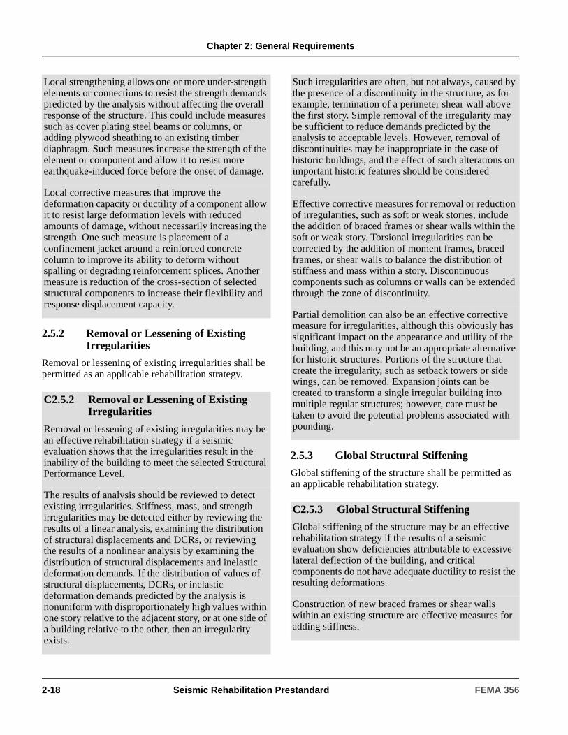
Chapter 2: General Requirements
2.5.2 Removal or Lessening of Existing Irregularities
Removal or lessening of existing irregularities shall be permitted as an applicable rehabilitation strategy.
2.5.3 Global Structural Stiffening
Global stiffening of the structure shall be permitted as an applicable rehabilitation strategy.
Local strengthening allows one or more under-strength elements or connections to resist the strength demands predicted by the analysis without affecting the overall response of the structure. This could include measures such as cover plating steel beams or columns, or adding plywood sheathing to an existing timber diaphragm. Such measures increase the strength of the element or component and allow it to resist more earthquake-induced force before the onset of damage.
Local corrective measures that improve the deformation capacity or ductility of a component allow it to resist large deformation levels with reduced amounts of damage, without necessarily increasing the strength. One such measure is placement of a confinement jacket around a reinforced concrete column to improve its ability to deform without spalling or degrading reinforcement splices. Another measure is reduction of the cross-section of selected structural components to increase their flexibility and response displacement capacity.
C2.5.2 Removal or Lessening of Existing Irregularities
Removal or lessening of existing irregularities may be an effective rehabilitation strategy if a seismic evaluation shows that the irregularities result in the inability of the building to meet the selected Structural Performance Level.
The results of analysis should be reviewed to detect existing irregularities. Stiffness, mass, and strength irregularities may be detected either by reviewing the results of a linear analysis, examining the distribution of structural displacements and DCRs, or reviewing the results of a nonlinear analysis by examining the distribution of structural displacements and inelastic deformation demands. If the distribution of values of structural displacements, DCRs, or inelastic deformation demands predicted by the analysis is nonuniform with disproportionately high values within one story relative to the adjacent story, or at one side of a building relative to the other, then an irregularity exists.
Such irregularities are often, but not always, caused by the presence of a discontinuity in the structure, as for example, termination of a perimeter shear wall above the first story. Simple removal of the irregularity may be sufficient to reduce demands predicted by the analysis to acceptable levels. However, removal of discontinuities may be inappropriate in the case of historic buildings, and the effect of such alterations on important historic features should be considered carefully.
Effective corrective measures for removal or reduction of irregularities, such as soft or weak stories, include the addition of braced frames or shear walls within the soft or weak story. Torsional irregularities can be corrected by the addition of moment frames, braced frames, or shear walls to balance the distribution of stiffness and mass within a story. Discontinuous components such as columns or walls can be extended through the zone of discontinuity.
Partial demolition can also be an effective corrective measure for irregularities, although this obviously has significant impact on the appearance and utility of the building, and this may not be an appropriate alternative for historic structures. Portions of the structure that create the irregularity, such as setback towers or side wings, can be removed. Expansion joints can be created to transform a single irregular building into multiple regular structures; however, care must be taken to avoid the potential problems associated with pounding.
C2.5.3 Global Structural Stiffening
Global stiffening of the structure may be an effective rehabilitation strategy if the results of a seismic evaluation show deficiencies attributable to excessive lateral deflection of the building, and critical components do not have adequate ductility to resist the resulting deformations.
Construction of new braced frames or shear walls within an existing structure are effective measures for adding stiffness.
2-18 Seismic Rehabilitation Prestandard FEMA 356
Chapter 2: General Requirements
2.5.4 Global Structural Strengthening
Global strengthening of the structure shall be permitted as an applicable rehabilitation strategy.
2.5.5 Mass Reduction
Reduction of mass in the building shall be permitted as an applicable rehabilitation strategy.
2.5.6 Seismic Isolation
Seismic isolation of the building shall be permitted as an applicable rehabilitation strategy in accordance with Chapter 9.
C2.5.4 Global Structural Strengthening
Global strengthening of the structure may be an effective rehabilitation strategy if the results of a seismic evaluation show unacceptable performance attributable to a global deficiency in structural strength. This can be identified when the onset of global inelastic behavior occurs at levels of ground shaking that are substantially less than the selected level of ground shaking or large DCRs (or inelastic deformation demands) are present throughout the structure. By providing supplemental strength to such a lateral-force-resisting system, it is possible to raise the threshold of ground motion at which the onset of damage occurs. Shear walls and braced frames are effective elements for this purpose, but they may be significantly stiffer than the structure to which they are added, which requires their design to provide nearly all of the structure’s lateral resistance. Moment-resisting frames, being more flexible, may be more compatible with existing elements in some structures; however, such flexible elements may not become effective in the building’s response until existing brittle elements have already been damaged.
C2.5.5 Mass Reduction
Mass reduction may be an effective rehabilitation strategy if the results of a seismic evaluation show deficiencies attributable to excessive building mass, global structural flexibility, or global structural weakness. Mass and stiffness control the amount of force and deformation induced in a structure by ground motion. Reductions in mass can result in direct reductions in both the amount of force and deformation demand produced by earthquakes and, therefore, can be used in lieu of structural strengthening and stiffening. Mass can be reduced through demolition of upper stories, replacement of heavy cladding and interior partitions, or removal of heavy storage and equipment loads.
C2.5.6 Seismic Isolation
Seismic isolation may be an effective rehabilitation strategy if the results of a seismic evaluation show deficiencies attributable to excessive seismic forces or deformation demands, or if it is desired to protect important contents and nonstructural components from damage. When a structure is seismically isolated, compliant bearings are inserted between the superstructure and its foundations. This produces a system (structure and isolation bearings) with a nearly rigid body translation of the structure above the bearings. Most of the deformation induced in the isolated system by the ground motion occurs within the compliant bearings, which are specifically designed to resist these concentrated displacements. Most bearings also have excellent energy dissipation characteristics (damping). Together, this results in greatly reduced demands on the existing elements of the structure, including contents and nonstructural components. For this reason, seismic isolation is often an appropriate strategy to achieve Enhanced Rehabilitation Objectives that include the protection of historic fabric, valuable contents, and equipment, or for buildings that contain important operations and functions. This technique is most effective for relatively stiff buildings with low profiles and large mass. It is less effective for light, flexible structures.
FEMA 356 Seismic Rehabilitation Prestandard 2-19

Chapter 2: General Requirements
2.5.7 Supplemental Energy Dissipation
Installation of supplemental energy dissipation devices shall be permitted as an applicable rehabilitation strategy in accordance with Chapter 9.
2.6 General Design RequirementsThe requirements of this section shall apply to all buildings for which the systematic rehabilitation method is selected for any target Building Performance Level and any selected seismic hazard unless specified otherwise.
2.6.1 Multidirectional Seismic Effects
Elements and components shall be designed to resist seismic forces acting in any horizontal direction. Seismic forces in the vertical direction shall be considered when required by Section 2.6.11. Multidirectional seismic effects shall be considered in the analysis as specified in Section 3.2.7.
2.6.2 P-∆ Effects
Elements and components of buildings shall be designed for P-∆ effects, defined as the combined effects of gravity loads acting in conjunction with lateral drifts due to seismic forces, as specified in Section 3.2.5.
2.6.3 Horizontal Torsion
Elements and components of buildings shall be designed to resist the effects of horizontal torsion as specified in Section 3.2.2.2.
2.6.4 Overturning
Elements and components of buildings shall be designed to resist the effects of overturning at each intermediate level as well as the base of the structure. Stability against overturning shall be evaluated as specified in Section 3.2.10. Effects of overturning on foundations shall be evaluated as specified in Section 4.4.
2.6.5 Continuity
All elements and components shall be tied together to form a complete load path for the transfer of inertial forces generated by the dynamic response of portions of the structure to the rest of the structure. Inertial forces specified in this section shall be considered force-controlled.
1. Smaller portions of a structure, such as an outstanding wing, shall be connected to the structure as a whole. Component connections shall be capable of resisting horizontal force in any direction calculated using Equation (2-3). These connections are not required if the individual portions of the structure are self-supporting and are separated by a seismic joint permitting independent movement during dynamic response.
(2-3)
C2.5.7 Supplemental Energy Dissipation
)Installation of supplemental energy dissipation devices may be an effective rehabilitation strategy if the results of a seismic evaluation show deficiencies attributable to excessive deformations due to global structural flexibility in a building. Many available technologies allow the energy imparted to a structure by ground motion to be dissipated in a controlled manner through the action of special devices—fluid viscous dampers (hydraulic cylinders), yielding plates, or friction pads—resulting in an overall reduction in the displacements of the structure. The most commonly used devices dissipate energy through frictional, hysteretic, or viscoelastic processes. In order to dissipate substantial energy, dissipation devices must typically undergo significant deformation (or stroke), which requires that the structural experience substantial lateral displacements. Therefore, these systems are most effective in structures that are relatively flexible and have some inelastic deformation capacity. Energy dissipaters are most commonly installed in structures as components of braced frames. Depending on the characteristics of the device, either static or dynamic stiffness is added to the structure as well as energy dissipation capacity (damping). In some cases, although the structural displacements are reduced, the forces delivered to the structure can actually be increased.
Fp 0.133SXS W=
2-20 Seismic Rehabilitation Prestandard FEMA 356

Chapter 2: General Requirements
where:
2. Components shall be connected to the structure to resist a horizontal force in any direction calculated using Equation (2-4) unless specified otherwise in Sections 2.6.6 and 2.6.7.
(2-4)
where:
exceptions:
1. For discrete connections resisting concentrated forces, Fp shall not be less than 1120 pounds.
2. For continuous connections, Fp shall not be less than 280 pounds per lineal foot.
3. Where a sliding support is provided at the end(s) of a component, the bearing length shall be sufficient to accommodate the expected differential displacement between the component and the support.
2.6.6 Diaphragms
Diaphragms shall be defined as horizontal elements that transfer earthquake-induced inertial forces to vertical elements of the lateral-force-resisting systems through the collective action of diaphragm components including chords, collectors, and ties.
Diaphragms shall be provided at each level of the structure as necessary to connect building masses to the primary vertical elements of the lateral-force-resisting system. The analytical model of the building shall account for the behavior of the diaphragms as specified in Section 3.2.4.
Diaphragms and their connections to vertical elements providing lateral support shall comply with the design requirements specified in Section 5.9 for metal diaphragms, Section 6.11 for concrete diaphragms, Section 6.12 for precast concrete diaphragms, and Section 8.6 for wood diaphragms.
2.6.6.1 Diaphragm Chords
Except for diaphragms evaluated as “unchorded” as specified in Chapter 8, a component shall be provided to develop horizontal shear stresses at each diaphragm edge (either interior or exterior). This component shall consist of either a continuous diaphragm chord, a continuous wall or frame element, or a continuous combination of wall, frame, and chord elements. The forces accumulated in these components and elements due to their action as diaphragm boundaries shall be considered. At re-entrant corners in diaphragms, and at the corners of openings in diaphragms, diaphragm chords shall be extended a distance sufficient to develop the accumulated diaphragm boundary stresses into the diaphragm beyond the corner.
2.6.6.2 Diaphragm Collectors
At each vertical element a diaphragm collector shall be provided to transfer to the element accumulated diaphragm forces that are in excess of the forces transferred directly to the element in shear. The diaphragm collector shall be extended beyond the element and attached to the diaphragm to transfer the accumulated forces.
2.6.6.3 Diaphragm Ties
Diaphragms shall be provided with continuous tension ties between chords or boundaries. Ties shall be spaced at a distance not exceeding three times the length of the tie. At a minimum, ties shall be designed for an axial tensile force calculated using Equation (2-5) as a force-controlled action.
(2-5)
Fp = Horizontal force in any direction for the design of connections between two portions of a structure
SXS = Spectral response acceleration parameter at short periods for the selected Earthquake Hazard Level and damping, adjusted for site class
W = Weight of the smaller portion of the structure
Fp = Horizontal force in any direction for the design of component connections to the structure
SXS = Spectral response acceleration parameter for short periods for the selected Earthquake Hazard Level and damping adjusted for site class
W = Weight of the component
Fp 0.08SXS W=
Fp 0.4SXS W=
FEMA 356 Seismic Rehabilitation Prestandard 2-21
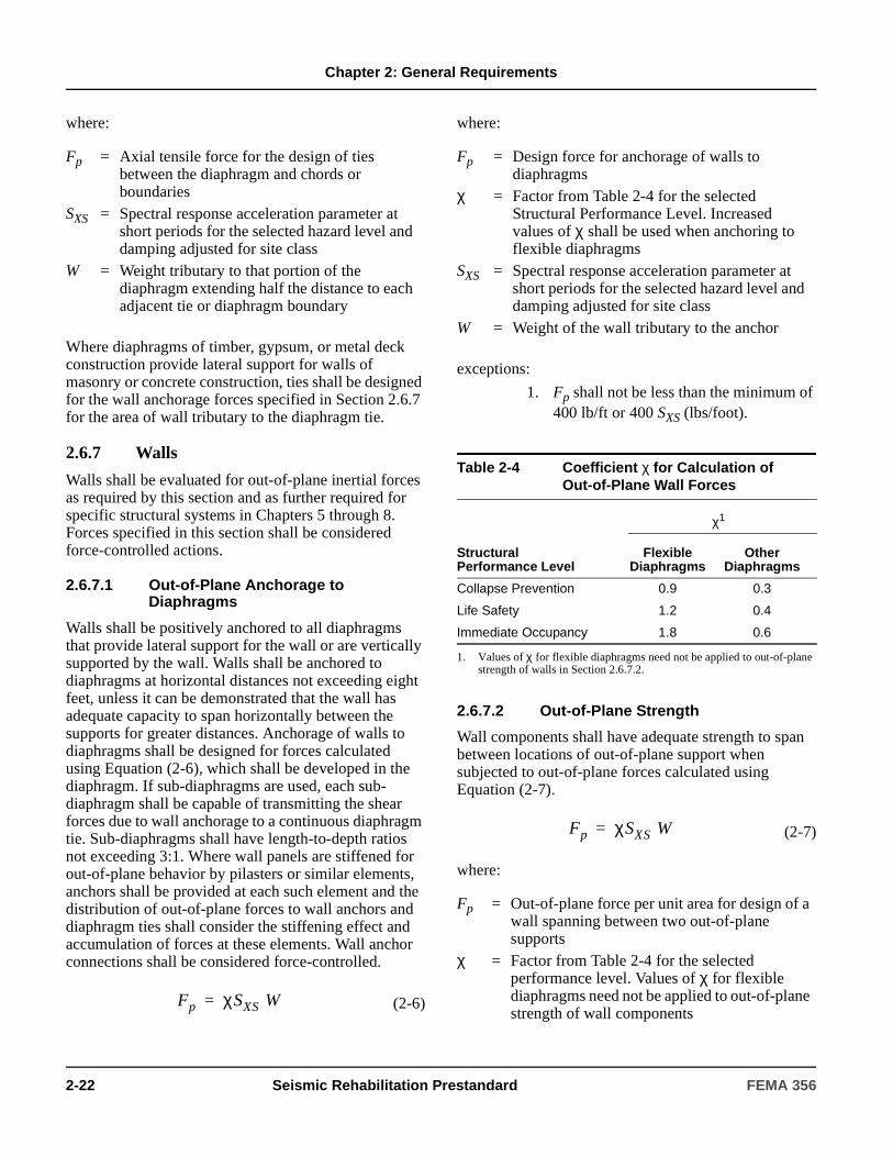
Chapter 2: General Requirements
where:
Where diaphragms of timber, gypsum, or metal deck construction provide lateral support for walls of masonry or concrete construction, ties shall be designed for the wall anchorage forces specified in Section 2.6.7 for the area of wall tributary to the diaphragm tie.
2.6.7 Walls
Walls shall be evaluated for out-of-plane inertial forces as required by this section and as further required for specific structural systems in Chapters 5 through 8. Forces specified in this section shall be considered force-controlled actions.
2.6.7.1 Out-of-Plane Anchorage to Diaphragms
Walls shall be positively anchored to all diaphragms that provide lateral support for the wall or are vertically supported by the wall. Walls shall be anchored to diaphragms at horizontal distances not exceeding eight feet, unless it can be demonstrated that the wall has adequate capacity to span horizontally between the supports for greater distances. Anchorage of walls to diaphragms shall be designed for forces calculated using Equation (2-6), which shall be developed in the diaphragm. If sub-diaphragms are used, each sub-diaphragm shall be capable of transmitting the shear forces due to wall anchorage to a continuous diaphragm tie. Sub-diaphragms shall have length-to-depth ratios not exceeding 3:1. Where wall panels are stiffened for out-of-plane behavior by pilasters or similar elements, anchors shall be provided at each such element and the distribution of out-of-plane forces to wall anchors and diaphragm ties shall consider the stiffening effect and accumulation of forces at these elements. Wall anchor connections shall be considered force-controlled.
(2-6)
where:
exceptions:
1. Fp shall not be less than the minimum of 400 lb/ft or 400 SXS (lbs/foot).
2.6.7.2 Out-of-Plane Strength
Wall components shall have adequate strength to span between locations of out-of-plane support when subjected to out-of-plane forces calculated using Equation (2-7).
(2-7)
where:
Fp = Axial tensile force for the design of ties between the diaphragm and chords or boundaries
SXS = Spectral response acceleration parameter at short periods for the selected hazard level and damping adjusted for site class
W = Weight tributary to that portion of the diaphragm extending half the distance to each adjacent tie or diaphragm boundary
Fp χSXS W=
Fp = Design force for anchorage of walls to diaphragms
χ = Factor from Table 2-4 for the selected Structural Performance Level. Increased values of χ shall be used when anchoring to flexible diaphragms
SXS = Spectral response acceleration parameter at short periods for the selected hazard level and damping adjusted for site class
W = Weight of the wall tributary to the anchor
Table 2-4 Coefficient χ for Calculation of Out-of-Plane Wall Forces
Structural Performance Level
χ1
1. Values of χ for flexible diaphragms need not be applied to out-of-plane strength of walls in Section 2.6.7.2.
Flexible Diaphragms
Other Diaphragms
Collapse Prevention 0.9 0.3
Life Safety 1.2 0.4
Immediate Occupancy 1.8 0.6
Fp = Out-of-plane force per unit area for design of a wall spanning between two out-of-plane supports
χ = Factor from Table 2-4 for the selected performance level. Values of χ for flexible diaphragms need not be applied to out-of-plane strength of wall components
Fp χSXS W=
2-22 Seismic Rehabilitation Prestandard FEMA 356
Chapter 2: General Requirements
2.6.8 Nonstructural Components
Nonstructural components, including architectural, mechanical and electrical components, shall be anchored and braced to the structure in accordance with the provisions of Chapter 11.
2.6.9 Structures Sharing Common Elements
Buildings sharing common vertical or lateral load-resisting elements shall be rehabilitated considering interconnection of the two structures, or they shall be separated as specified in this section.
2.6.9.1 Interconnection
Buildings sharing common elements, other than foundation elements, shall be thoroughly tied together so as to behave as an integral unit. Ties between the structures at each level shall be designed for the forces specified in Section 2.6.5. Analyses of the combined response of the buildings shall account for the interconnection of the structures and shall evaluate the structures as one integral unit.
If the shared common elements are foundation elements, and the superstructures meet the separation requirements of Section 2.6.10, the structures need not be tied together. Shared foundation elements shall be designed considering an analysis of the combined response of the two buildings.
2.6.9.2 Separation
Buildings sharing common elements shall be completely separated by introducing seismic joints between the structures meeting the requirements of Section 2.6.10. Independent lateral-force-resisting systems shall be provided for each structure. Independent vertical support shall be provided on each side of the seismic joint, unless slide bearings are used and adequate bearing length is provided to accommodate the expected independent lateral movement of each structure. It shall be assumed for such purposes that the structures move out of phase with each other in opposite directions simultaneously. The original shared element shall be either completely removed, or anchored to one of the structures in accordance with the applicable requirements of Section 2.6.5.
2.6.10 Building Separation
2.6.10.1 Minimum Separation
Buildings shall be separated from adjacent structures to prevent pounding by a minimum distance si at any level i given by Equation (2-8) unless exempted as specified in Section 2.6.10.2.
(2-8)
where:
The value of si need not exceed 0.04 times the height of the level under consideration above grade at the location of potential impact.
SXS = Spectral response acceleration at short periods for the selected hazard level and damping adjusted for site class
W = Weight of the wall per unit area
∆i1 = Lateral deflection of the building under consideration, at level i, relative to the ground, calculated in accordance with the provisions of this standard for the selected hazard level
∆i2 = Lateral deflection of an adjacent building, at level i, relative to the ground, estimated using the provisions of this standard or other approved approximate procedure. Alternatively, it shall be permitted to assume ∆i2 = (0.03) (hi) for any structure in lieu of a more detailed analysis, where hi is the height of level i above grade
si ∆i12 ∆i2
2+=
FEMA 356 Seismic Rehabilitation Prestandard 2-23

Chapter 2: General Requirements
2.6.10.2 Exceptions
For Structural Performance Levels of life safety or lower, buildings adjacent to structures that have diaphragms located at the same elevation, and differ in height by less than 50% of the height of the shorter building, need not meet the minimum separation distance specified in Section 2.6.10.1.
Buildings rehabilitated using an approved analysis procedure that accounts for the change in dynamic response of the structures due to impact need not meet the minimum separation distance specified in Section 2.6.10.1. Such an analysis shall demonstrate that:
1. The structures are capable of transferring forces resulting from impact when diaphragms are located at the same elevation; or
2. The structures are capable of resisting all required vertical and lateral forces considering the loss of any elements or components damaged by impact of the structures.
2.6.11 Vertical Seismic Effects
The effects of the vertical response of a structure to earthquake ground motion shall be considered for the following cases:
1. Cantilever elements and components of structures.
2. Pre-stressed elements and components of structures.
3. Structural components in which demands due to gravity loads specified in Section 3.2.8 exceed 80% of the nominal capacity of the component.
2.7 Construction Quality AssuranceConstruction of seismic rehabilitation work shall be checked for quality of construction and general compliance with the intent of the plans and specifications of the rehabilitation design. Construction quality assurance shall conform to the requirements of this section and the additional testing and inspection requirements of the building code and reference standards of Chapters 5 through 11.
C2.6.10.2 Exceptions
This standard permits rehabilitated buildings to experience pounding as long as the effects are adequately considered by analysis methods that account for the transfer of momentum and energy between the structures as they impact.
Approximate methods of acounting for these effects can be obtained by performing nonlinear time history analyses of both structures (Johnson 1992). Approximate elastic methods for evaluating these effects have also been developed and are presented in the literature (Kasai 1990).
Buildings that are likely to experience significant pounding should not be considered capable of meeting Enhanced Rehabilitation Objectives. This is because signficant local crushing of building components is likely to occur at points of impact. Further, the very nature of the impact is such that high frequency shocks can be transmitted through the structures and potentially be very damaging to architectural elements, and mechanical and electrical systems. Such damage is not consistent with the performance expected of buildings designed to Enhahced Rehabilitation Objectives.
C2.7 Construction Quality AssuranceThe design professional responsible for the seismic rehabilitation of a specific building may find it appropriate to specify more stringent or more detailed requirements. Such additional requirements may be particularly appropriate for those buildings having Enhanced Rehabilitation Objectives.
2-24 Seismic Rehabilitation Prestandard FEMA 356
Chapter 2: General Requirements
2.7.1 Construction Quality Assurance Plan
A Quality Assurance Plan (QAP) shall be prepared by the design professional and approved by the code official. The QAP shall identify components of the work that are subject to quality assurance procedures and identify special inspection, testing, and observation requirements to confirm construction quality. The QAP shall also include a process for modifying the rehabilitation design to reflect unforeseen conditions discovered during construction.
2.7.2 Construction Quality Assurance Requirements
2.7.2.1 Requirements for the Design Professional
The design professional shall be responsible for preparing the QAP applicable to the portion of the work for which they are in responsible charge, overseeing the implementation of the plan, and reviewing special inspection and testing reports.
The design professional shall be responsible for performing periodic structural observation of the rehabilitation work. Structural observation shall be performed at significant stages of construction, and shall include visual observation of the work for substantial conformance with the construction documents and confirmation of conditions assumed during design. Structural observation shall be performed in addition to any special inspection and testing that is otherwise required for the work.
The design professional shall be responsible for modifying the rehabilitation design to reflect conditions discovered during construction.
2.7.2.2 Special Inspection
The owner shall engage the services of a special inspector to observe construction of the following rehabilitation work:
1. Items designated in Section A.9.3.3 of Appendix A of ASCE 7
2. All other elements and components designated for such special inspection by the design professional.
2.7.2.3 Testing
The special inspector shall be responsible for verifying that special test requirements, as described in the QAP, are performed by an approved testing agency for the following rehabilitation work:
1. All work described in Section A.9.3.4 of Appendix A of ASCE 7
2. Other work designated for such testing by the design professional.
C2.7.1 Construction Quality Assurance Plan
The QAP should, as a minimum, include the following:
1. Required contractor quality control procedures.
2. Required design professional construction quality assurance services, including but not limited to the following:
2.1. Review of required contractor submittals.
2.2. Monitoring of required inspection reports and test results.
2.3. Construction consultation as required by the contractor on the intent of the construction documents.
2.4. Construction observation in accordance with Section 2.7.2.1.
C2.7.2.1 Requirements for the Design Professional
Following structural observations, the design professional should report any observed deficiencies in writing to the owner’s representative, the special inspector, the contractor, and the code official. Upon completion of the work, the design professional should submit to the code official a written statement attesting that the site visits have been made, and identifying any reported deficiencies that, to the best of the structural construction observer’s knowledge, have been resolved or rectified.
FEMA 356 Seismic Rehabilitation Prestandard 2-25

Chapter 2: General Requirements
2.7.2.4 Reporting and Compliance Procedures
The special inspector shall furnish copies of progress reports to the owner’s representative and the design professional, noting any uncorrected deficiencies and corrections of previously reported deficiencies. All observed deficiencies shall be brought to the immediate attention of the contractor for correction.
Upon completion of construction, the special inspector shall submit a final report to the owner’s representative and the design professional, indicating the extent to which inspected work was completed in accordance with approved construction documents. Non-compliant work shall have been corrected prior to completion of construction.
2.7.3 Responsibilities of the Code Official
The code official shall be responsible for reviewing and approving the QAP and specifying minimum special inspection, testing, and reporting requirements.
C2.7.3 Responsibilities of the Code Official
The code official should act to enhance and encourage the protection of the public that is represented by such rehabilitation. These actions should include those described in the following subsections.
1. Construction Document Submittals— Permitting
As part of the permitting process, the code official should require that construction documents be submitted for a permit to construct the proposed seismic rehabilitation measures. The documents should include a statement of the design basis for the rehabilitation, drawings (or adequately detailed sketches), structural/seismic calculations, and a QAP as recommended by Section 2.7.1. Appropriate structural construction specifications are also recommended, if structural requirements are not adequately defined by notes on drawings.
The code official should require that it be demonstrated (in the design calculations, by third-party review, or by other means) that the design of the seismic rehabilitation measures has been performed in conformance with local building regulations, the stated design basis, the intent of this standard, and/or accepted engineering principles. The code official should be aware that compliance with the building code provisions for new structures is often not possible and is not required by this standard. It is not intended that the code official assure compliance of the submittals with the structural requirements for new construction.
The code official should maintain a permanent public file of the construction documents submitted as part of the permitting process for construction of the seismic rehabilitation measures.
2. Construction Phase Role
The code official should monitor the implementation of the QAP. In particular, the following actions should be taken.
2.1 Files of inspection reports should be maintained for a defined length of time following completion of construction and issuance of a certificate of occupancy. These files should include both reports submitted by special inspectors employed by the owner, as in Section 2.7.2.2, and those submitted by inspectors employed by the code official.
2.2 Prior to issuance of certificates of occupancy, the code official should ascertain that either all reported noncompliant aspects of construction have been rectified, or such noncompliant aspects have been accepted by the design professional in responsible charge as acceptable substitutes that are consistent with the general intent of the construction documents.
2.3 Files of test reports prepared in accordance with Section 2.7.2.4 should be maintained for a defined length of time following completion of construction and issuance of a certificate of occupancy.
2-26 Seismic Rehabilitation Prestandard FEMA 356
Chapter 2: General Requirements
2.8 Alternative Modeling Parameters and Acceptance Criteria
For elements, components, systems, and materials for which structural modeling parameters and acceptance criteria are not provided in this standard, it shall be permitted to derive the required parameters and acceptance criteria using the experimentally obtained cyclic response characteristics of the assembly, determined in accordance with this section. Approved independent review of this process shall be conducted.
2.8.1 Experimental Setup
When relevant data on the inelastic force-deformation behavior for a structural subassembly (elements or components) are not available, such data shall be obtained from experiments consisting of physical tests of representative subassemblies as specified in this section. Each subassembly shall be an identifiable portion of the structural element or component, the stiffness of which is required to be modeled as part of the structural analysis process. The objective of the experiment shall be to estimate the lateral-force-displacement relationships (stiffness) for the subassemblies at different loading increments, together with the strength and deformation capacities for the desired Structural Performance Levels. These properties shall be used in developing an analytical model of the structure to calculate its response to earthquake ground shaking and other hazards, and in developing acceptance criteria for strength and deformations. The limiting strength and deformation capacities shall be determined from the experimental program using the average values of a minimum of three tests performed for the same design configuration and test conditions.
The experimental setup shall replicate the construction details, support and boundary conditions, and loading conditions expected in the building. The loading shall consist of fully reversed cyclic loading at increasing displacement levels with the number of cycles and displacement levels based on expected response of the structure to the design earthquake. Increments shall be continued until the subassembly exhibits complete failure, characterized by the loss of lateral- and gravity-load resistance.
2.8.2 Data Reduction and Reporting
A report shall be prepared for each experiment. The report shall include the following:
1. Description of the subassembly being tested.
2. Description of the experimental setup, including:
2.1. Details on fabrication of the subassembly,
2.2. Location and date of experiment,
2.3. Description of instrumentation employed,
2.4. Name of the person in responsible charge of the test, and
2.5. Photographs of the specimen, taken prior to testing.
3. Description of the loading protocol employed, including:
3.1. Increment of loading (or deformation) applied,
3.2. Rate of loading application, and
3.3. Duration of loading at each stage.
4. Description, including photographic documentation, and limiting deformation value for all important behavior states observed during the test, including the following, as applicable:
4.1. Elastic range with effective stiffness reported,
4.2. Plastic range,
4.3. Onset of visible damage,
4.4. Loss of lateral-force-resisting capacity,
4.5. Loss of vertical-load-carrying capacity,
4.6. Force-deformation plot for the subassembly (noting the various behavior states), and
4.7. Description of limiting behavior states defined as the onset of specific damage mode, change in stiffness or behavior (e.g., initiation of cracking or yielding) and failure modes.
FEMA 356 Seismic Rehabilitation Prestandard 2-27
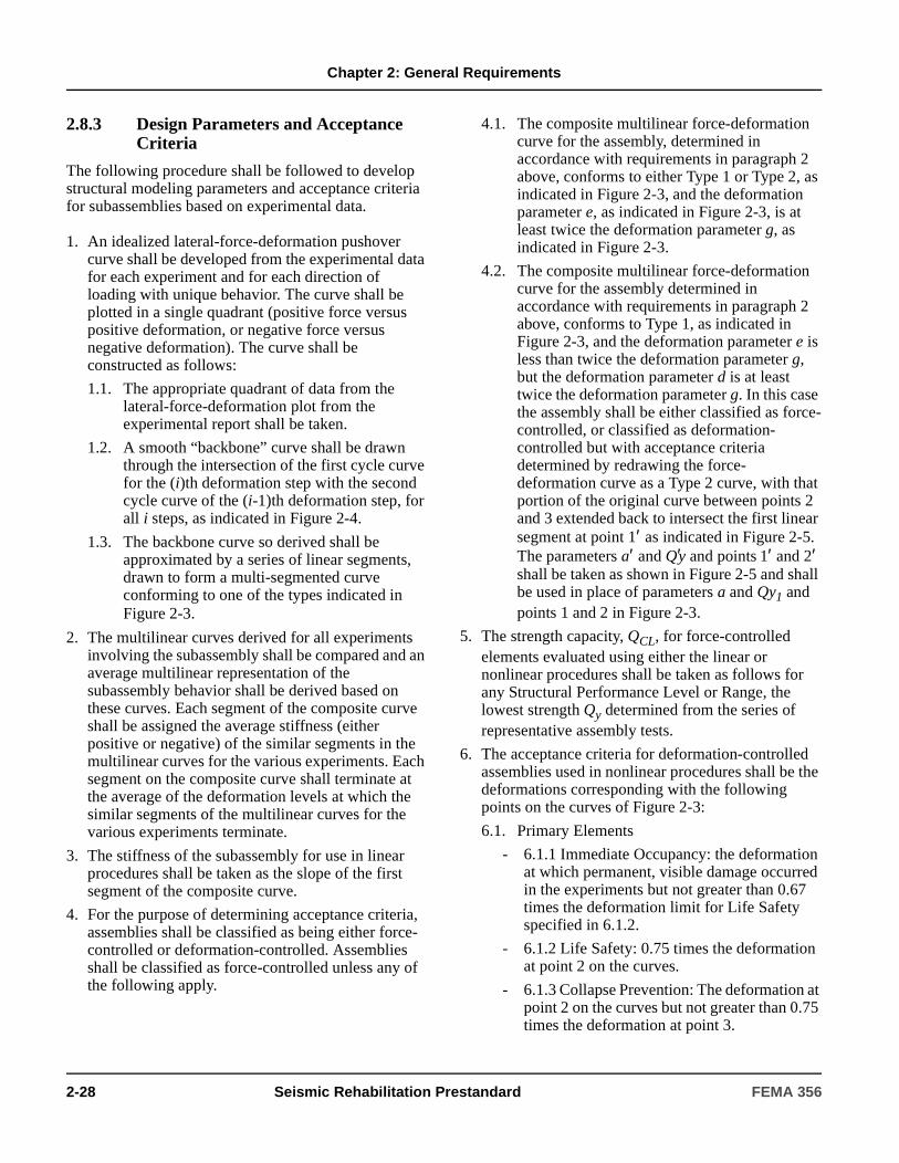
Chapter 2: General Requirements
2.8.3 Design Parameters and Acceptance Criteria
The following procedure shall be followed to develop structural modeling parameters and acceptance criteria for subassemblies based on experimental data.
1. An idealized lateral-force-deformation pushover curve shall be developed from the experimental data for each experiment and for each direction of loading with unique behavior. The curve shall be plotted in a single quadrant (positive force versus positive deformation, or negative force versus negative deformation). The curve shall be constructed as follows:
1.1. The appropriate quadrant of data from the lateral-force-deformation plot from the experimental report shall be taken.
1.2. A smooth “backbone” curve shall be drawn through the intersection of the first cycle curve for the (i)th deformation step with the second cycle curve of the (i-1)th deformation step, for all i steps, as indicated in Figure 2-4.
1.3. The backbone curve so derived shall be approximated by a series of linear segments, drawn to form a multi-segmented curve conforming to one of the types indicated in Figure 2-3.
2. The multilinear curves derived for all experiments involving the subassembly shall be compared and an average multilinear representation of the subassembly behavior shall be derived based on these curves. Each segment of the composite curve shall be assigned the average stiffness (either positive or negative) of the similar segments in the multilinear curves for the various experiments. Each segment on the composite curve shall terminate at the average of the deformation levels at which the similar segments of the multilinear curves for the various experiments terminate.
3. The stiffness of the subassembly for use in linear procedures shall be taken as the slope of the first segment of the composite curve.
4. For the purpose of determining acceptance criteria, assemblies shall be classified as being either force- controlled or deformation-controlled. Assemblies shall be classified as force-controlled unless any of the following apply.
4.1. The composite multilinear force-deformation curve for the assembly, determined in accordance with requirements in paragraph 2 above, conforms to either Type 1 or Type 2, as indicated in Figure 2-3, and the deformation parameter e, as indicated in Figure 2-3, is at least twice the deformation parameter g, as indicated in Figure 2-3.
4.2. The composite multilinear force-deformation curve for the assembly determined in accordance with requirements in paragraph 2 above, conforms to Type 1, as indicated in Figure 2-3, and the deformation parameter e is less than twice the deformation parameter g, but the deformation parameter d is at least twice the deformation parameter g. In this case the assembly shall be either classified as force-controlled, or classified as deformation-controlled but with acceptance criteria determined by redrawing the force-deformation curve as a Type 2 curve, with that portion of the original curve between points 2 and 3 extended back to intersect the first linear segment at point 1′ as indicated in Figure 2-5. The parameters a′ and Q′y and points 1′ and 2′ shall be taken as shown in Figure 2-5 and shall be used in place of parameters a and Qy1 and points 1 and 2 in Figure 2-3.
5. The strength capacity, QCL, for force-controlled elements evaluated using either the linear or nonlinear procedures shall be taken as follows for any Structural Performance Level or Range, the lowest strength Qy determined from the series of representative assembly tests.
6. The acceptance criteria for deformation-controlled assemblies used in nonlinear procedures shall be the deformations corresponding with the following points on the curves of Figure 2-3:
6.1. Primary Elements
- 6.1.1 Immediate Occupancy: the deformation at which permanent, visible damage occurred in the experiments but not greater than 0.67 times the deformation limit for Life Safety specified in 6.1.2.
- 6.1.2 Life Safety: 0.75 times the deformation at point 2 on the curves.
- 6.1.3 Collapse Prevention: The deformation at point 2 on the curves but not greater than 0.75 times the deformation at point 3.
2-28 Seismic Rehabilitation Prestandard FEMA 356
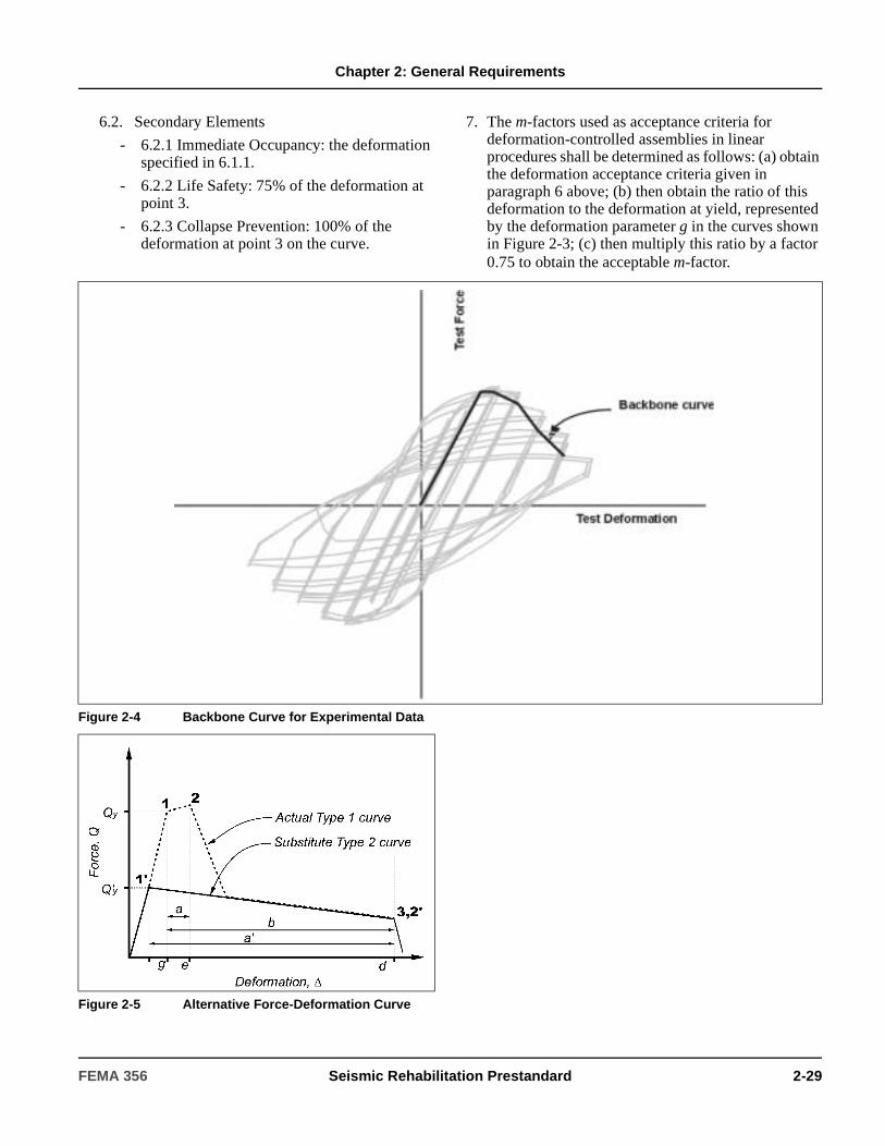
Chapter 2: General Requirements
6.2. Secondary Elements
- 6.2.1 Immediate Occupancy: the deformation specified in 6.1.1.
- 6.2.2 Life Safety: 75% of the deformation at point 3.
- 6.2.3 Collapse Prevention: 100% of the deformation at point 3 on the curve.
7. The m-factors used as acceptance criteria for deformation-controlled assemblies in linear procedures shall be determined as follows: (a) obtain the deformation acceptance criteria given in paragraph 6 above; (b) then obtain the ratio of this deformation to the deformation at yield, represented by the deformation parameter g in the curves shown in Figure 2-3; (c) then multiply this ratio by a factor 0.75 to obtain the acceptable m-factor.
Figure 2-4 Backbone Curve for Experimental Data
Figure 2-5 Alternative Force-Deformation Curve
FEMA 356 Seismic Rehabilitation Prestandard 2-29

Chapter 2: General Requirements
2-30 Seismic Rehabilitation Prestandard FEMA 356
3. Analysis Procedures
3.1 ScopeThis chapter sets forth requirements for analysis of buildings using the Systematic Rehabilitation Method. Section 3.2 specifies general analysis requirements for the mathematical modeling of buildings including basic assumptions, consideration of torsion, diaphragm flexibility, P-∆ effects, soil-structure interaction, multidirectional effects, and overturning. Section 3.3 defines four analysis procedures included in this standard. Section 3.4 defines component acceptance criteria.
Analysis of buildings with seismic isolation or energy dissipation systems shall comply with the requirements of Chapter 9. Analysis of buildings using the Simplified Rehabilitation Method shall comply with the requirements of Chapter 10.
3.2 General Analysis RequirementsAn analysis of the building, as specified in Section 2.4, shall be conducted in accordance with the requirements of this section and Section 2.6.
3.2.1 Analysis Procedure Selection
An analysis of the building shall be performed using the Linear Static Procedure (LSP), Linear Dynamic Procedure (LDP), Nonlinear Static Procedure (NSP), or Nonlinear Dynamic Procedure (NDP) selected based on the limitations specified in Section 2.4. Use of alternative rational analysis procedures as described in Section 2.4.3 shall also be permitted.
C3.1 ScopeThe relationship of the analysis procedures described in this chapter with specifications in other chapters of this standard is as follows.
• Information on Rehabilitation Objectives, including Earthquake Hazard Levels and target Building Performance Levels, is provided in Chapter 1.
• The provisions set forth in this chapter are intended for Systematic Rehabilitation. Provisions for Simplified Rehabilitation are presented in Chapter 10.
• Guidelines for selecting an appropriate analysis procedure are provided in Chapter 2. Chapter 3 describes the loading requirements, mathematical model, and detailed analytical procedures required to estimate seismic force and deformation demands on elements and components of a building. Information on the calculation of appropriate stiffness and strength characteristics for components and elements is provided in Chapters 4 through 9.
• General design requirements are specified in Section 2.6 for multidirectional excitation effects, P-∆ effects, horizontal torsion, overturning, continuity of the framing system, diaphragms, walls, nonstructural components, building separation, structures sharing common components, and vertical seismic effects.
• Component strength and deformation demands obtained from analysis using procedures described in this chapter, based on component acceptance criteria outlined in this chapter, are compared with permissible values provided in Chapters 4 through 9 for the desired performance level.
• Design methods for walls subjected to out-of-plane seismic forces are addressed in Chapter 2. Analysis and design methods for nonstructural components and mechanical and electrical equipment are presented in Chapter 11.
C3.2.1 Analysis Procedure Selection
Four procedures are presented for seismic analysis of buildings: two linear procedures, and two nonlinear procedures. The two linear procedures are termed the Linear Static Procedure (LSP) and the Linear Dynamic Procedure (LDP). The two nonlinear procedures are termed the Nonlinear Static Procedure (NSP) and Nonlinear Dynamic Procedure (NDP).
FEMA 356 Seismic Rehabilitation Prestandard 3-1
Chapter 3: Analysis Procedures
3.2.2 Mathematical Modeling
3.2.2.1 Basic Assumptions
A building shall be modeled, analyzed, and evaluated as a three-dimensional assembly of elements and components. Alternatively, use of a two-dimensional model shall permitted if the building meets one of the following conditions:
1. The building has rigid diaphragms as defined in Section 3.2.4 and horizontal torsion effects do not exceed the limits specified in Section 3.2.2.2, or horizontal torsion effects are accounted for as specified in Section 3.2.2.2.
2. The building has flexible diaphragms as defined in Section 3.2.4.
If two-dimensional models are used, the three-dimensional nature of components and elements shall be considered when calculating stiffness and strength properties.
If the building contains out-of-plane offsets in vertical lateral-force-resisting elements, the model shall explicitly account for such offsets in the determination of diaphragm demands.
Modeling stiffness of structural components shall be based on the stiffness requirements of Chapters 4 through 8.
For nonlinear procedures, a connection shall be explicitly modeled if the connection is weaker, has less ductility than the connected components, or the flexibility of the connection results in a change in the connection forces or deformations greater than 10%.
3.2.2.2 Horizontal Torsion
The effects of horizontal torsion shall be considered in accordance with this section. Torsion need not be considered in buildings with flexible diaphragms as defined in Section 3.2.4.
Either the linear procedures of Section 3.3.1 and Section 3.3.2 or the nonlinear procedures of Sections 3.3.3 and 3.3.4 may be used to analyze a building, subject to the limitations set forth in Section 2.4.
Linear procedures are appropriate when the expected level of nonlinearity is low. This is measured by component demand to capacity ratios (DCRs) of less than 2.0.
Static procedures are appropriate when higher mode effects are not significant. This is generally true for short, regular buildings. Dynamic procedures are required for tall buildings, buildings with torsional irregularities, or non-orthogonal systems.
The Nonlinear Static Procedure is acceptable for most buildings, but should be used in conjunction with the Linear Dynamic Procedure if mass participation in the first mode is low.
The term “linear” in linear analysis procedures implies “linearly elastic.” The analysis procedure, however, may include geometric nonlinearity of gravity loads acting through lateral displacements and implicit material nonlinearity of concrete and masonry components using properties of cracked sections. The term “nonlinear” in nonlinear analysis procedures implies explicit material nonlinearity or inelastic material response, but geometric nonlinearity may also be included.
C3.2.2.1 Basic Assumptions
For two-dimensional models, the three-dimensional nature of components and elements should be recognized in calculating their stiffness and strength properties. For example, shear walls and other bracing systems may have “L” or “T” or other three-dimensional cross-sections where contributions of both the flanges and webs should be accounted for in calculating stiffness and strength properties.
In this standard, component stiffness is generally taken as the effective stiffness based on the secant stiffness to yield level forces. Specific direction on calculating effective stiffness is provided in each material chapter for each type of structural system.
Examples of where connection flexibility may be important to model include the panel zone of steel moment-resisting frames and the “joint” region of perforated masonry or concrete walls.
3-2 Seismic Rehabilitation Prestandard FEMA 356
Chapter 3: Analysis Procedures
3.2.2.2.1 Total Torsional Moment
The total horizontal torsional moment at a story shall be equal to the sum of the actual torsional moment and accidental torsional moment calculated as follows:
1. The actual torsional moment at a story shall be calculated by multiplying the seismic story shear force by the eccentricity between the center of mass and the center of rigidity measured perpendicular to the direction of the applied load. The center of mass shall be based on all floors above the story under consideration. The center of rigidity of a story shall include all vertical seismic elements in the story.
2. The accidental torsion moment at a story shall be calculated as the seismic story shear force multiplied by a distance equal to 5% of the horizontal dimension at the given floor level measured perpendicular to the direction of the applied load.
3.2.2.2.2 Consideration of Torsional Effects
Effects of horizontal torsion shall be considered in accordance with the following requirements:
1. Increased forces and displacements due to actual torsion shall be calculated for all buildings.
2. The displacement multiplier, η, at each floor shall be calculated as the ratio of the maximum displacement at any point on the floor diaphragm to the average displacement (δmax/δavg). Displacements shall be calculated for the applied loads.
3. Increased forces and displacements due to accidental torsion shall be considered unless the accidental torsional moment is less than 25 percent of the actual torsional moment, or the displacement multiplier η due to the applied load and accidental torsion is less than 1.1 at every floor.
4. For linear analysis procedures, forces and displacements due to accidental torsion shall be amplified by a factor, Ax, as defined by Equation (3-1), when the displacement multiplier η due to total torsional moment exceeds 1.2 at any level.
(3-1)
5. If the displacement modifier η due to total torsional moment at any floor exceeds 1.50, two-dimensional models shall not be permitted and three-dimensional models that account for the spatial distribution of mass and stiffness shall be used.
6. When two-dimensional models are used, the effects of horizontal torsion shall be calculated as follows.
6.1. For the LSP and the LDP, forces and displacements shall be amplified by the maximum value of η calculated for the building.
6.2. For the NSP, the target displacement shall be amplified by the maximum value of η calculated for the building.
6.3. For the NDP, the amplitude of the ground acceleration record shall be amplified by the maximum value of η calculated for the building.
7. The effects of accidental torsion shall not be used to reduce force and deformation demands on components and elements.
Ax
ηx
1.2-------
2 3.0≤=
C3.2.2.2 Horizontal Torsion
Actual torsion is due to the eccentricity between centers of mass and stiffness. Accidental torsion is intended to cover the effects of the rotational component of the ground motion, differences between computed and actual stiffness, and unfavorable distributions of dead and live load masses.
The 10% threshold on additional displacement due to accidental torsion is based on judgment. The intent is to reward those building frames that are torsionally redundant and possess high torsional stiffness. Such structures are likely to be much less susceptible to torsional response than those framing systems possessing low redundancy and low torsional stiffness.
FEMA 356 Seismic Rehabilitation Prestandard 3-3

Chapter 3: Analysis Procedures
3.2.2.3 Primary and Secondary Elements and Components
Elements and components shall be classified as primary or secondary as defined in Section 2.4.4.2. Primary elements and components shall be evaluated for earthquake-induced forces and deformations in combination with gravity load effects. Secondary elements and components shall be evaluated for earthquake-induced deformations in combination with gravity load effects.
Mathematical models for use with linear analysis procedures shall include the stiffness and resistance of only the primary elements and components. If the total lateral stiffness of secondary elements exceeds 25% of the total initial stiffness of primary elements, some secondary elements shall be reclassified as primary to reduce the total stiffness of secondary elements to less than 25% of primary. If the exclusion of a secondary element will reduce the force or deformation demands on a primary element, the secondary element shall be included in the model.
Mathematical models for use with nonlinear procedures shall include the stiffness and resistance of primary and secondary elements and components. The strength and stiffness degradation of primary and secondary elements and components shall be explicitly modeled. For the simplified NSP of Section 3.3.3.2.1, only primary elements and components shall be included in the model and degradation shall not be modeled.
Nonstructural components shall be included in mathematical models if their lateral stiffness exceeds 10% of the total initial lateral stiffness of a story.
Components and elements shall not be selectively designated primary or secondary to change the configuration of a building from irregular to regular.
3.2.2.4 Stiffness and Strength Assumptions
Stiffness and strength properties of components and elements shall be determined in accordance with the requirements of Chapters 4 through 9, and 11.
3.2.2.5 Foundation Modeling
The foundation system shall be modeled considering the degree of fixity provided at the base of the structure. Rigid or flexible base assumptions shall be permitted in accordance with the requirements of Section 4.4.3. The foundation modeling shall consider movement due to geologic site hazards specified in Section 4.2.2.
3.2.3 Configuration
Building irregularities defined in Section 2.4.1.1 shall be based on the plan and vertical configuration of the rehabilitated structure. A structure defined as regular shall not have any irregularity defined in Section 2.4.1.1, both with and without the contribution of secondary components.
3.2.4 Diaphragms
3.2.4.1 General
Diaphragms shall be classified as either flexible, stiff, or rigid in accordance with Section 3.2.4.2.
C3.2.2.3 Primary and Secondary Elements and Components
In linear analysis procedures, the 25% limit for the lateral stiffness of the secondary components and elements can be checked by initially including the secondary components and elements in the mathematical model and examining their stiffness contribution.
C3.2.3 Configuration
One objective of seismic rehabilitation should be the improvement of the regularity of a building through the judicious placement of new framing elements.
Adding seismic framing elements at certain locations will improve the regularity of the building and should be considered as a means to improve seismic performance of the building.
Secondary components can lose significant strength and stiffness after initial earthquake shaking and may no longer be effective. Therefore, regularity of the building should be determined independent of the contribution of secondary components.
3-4 Seismic Rehabilitation Prestandard FEMA 356

Chapter 3: Analysis Procedures
3.2.4.2 Classification of Diaphragms
Diaphragms shall be classified as flexible when the maximum horizontal deformation of the diaphragm along its length is more than twice the average interstory drift of the vertical lateral-force-resisting elements of the story immediately below the diaphragm. For diaphragms supported by basement walls, the average interstory drift of the story above the diaphragm shall be used.
Diaphragms shall be classified as rigid when the maximum lateral deformation of the diaphragm is less than half the average interstory drift of the vertical lateral-force-resisting elements of the associated story.
Diaphragms that are neither flexible nor rigid shall be classified as stiff.
For the purpose of classifying diaphragms, interstory drift and diaphragm deformations shall be calculated using the pseudo lateral load specified in Equation (3-10). The in-plane deflection of the diaphragm shall be calculated for an in-plane distribution of lateral force consistent with the distribution of mass, and all in-plane lateral forces associated with offsets in the vertical seismic framing at that diaphragm level.
3.2.4.3 Mathematical Modeling
Mathematical modeling of buildings with rigid diaphragms shall account for the effects of horizontal torsion as specified in Section 3.2.2.2. Mathematical models of buildings with stiff or flexible diaphragms shall account for the effects of diaphragm flexibility by modeling the diaphragm as an element with an in-plane stiffness consistent with the structural characteristics of the diaphragm system. Alternatively, for buildings with flexible diaphragms at each floor level, each lateral-force-resisting element in a vertical plane shall be permitted to be designed independently, with seismic masses assigned on the basis of tributary area. 3.2.5 P-∆ Effects
Buildings shall be evaluated for static P-∆ effects and dynamic P-∆ effects as specified in this section.
3.2.5.1 Static P-∆ Effects
Static P-∆ effects shall be included in linear or nonlinear analysis procedures as specified in Sections 3.2.5.1.1 and 3.2.5.1.2, respectively.
C3.2.4 Diaphragms
Evaluation of diaphragm demands should be based on the likely distribution of horizontal inertia forces. For flexible diaphragms, such a distribution may be given by Equation (C3-1) and illustrated in Figure C3-1 below.
(C3-1)
where:
fd = Inertial load per foot
Fd = Total inertial load on a flexible diaphragm
x = Distance from the center line of flexible diaphragm
Ld = Distance between lateral support points for diaphragm
Figure C3-1 Plausible Force Distribution in a Flexible Diaphragm
fd
1.5Fd
Ld-------------- 1
2xLd------
2–=
FEMA 356 Seismic Rehabilitation Prestandard 3-5
Chapter 3: Analysis Procedures
3.2.5.1.1 Linear Procedures
For linear procedures, the stability coefficient θ shall be evaluated for each story in the building and for each direction of response using Equation (3-2).
(3-2)
where:
When the stability coefficient θi is less than 0.1 in all stories, the P-∆ effects need not be considered. If the stability coefficient lies between 0.1 and 0.33, seismic forces and deformations in story i shall be increased by the factor 1/(1– θi). When the stability coefficient θi exceeds 0.33, the structure shall be considered unstable and the rehabilitation design modified to reduce the computed lateral deflections in the story to comply with this limitation.
3.2.5.1.2 Nonlinear Procedures
For nonlinear procedures, static P-∆ effects shall be incorporated in the analysis by including in the mathematical model the nonlinear force-deformation relationship of all elements and components subjected to axial forces.
3.2.5.2 Dynamic P-∆ Effects
Dynamic P-∆ effects shall be included using the coefficient C3 defined for linear procedures in Section 3.3.1.3.1 or for the NSP in Section 3.3.3.3.2.
3.2.6 Soil-Structure Interaction
The effects of soil-structure interaction (SSI) shall be evaluated for those buildings in which an increase in fundamental period due to SSI effects will result in an increase in spectral accelerations. For other buildings, the effects of SSI need not be evaluated.
Pi = Portion of the total weight of the structure including dead, permanent live, and 25% of transient live loads acting on the columns and bearing walls within story level i
Vi = The total calculated lateral shear force in the direction under consideration at story i due to earthquake response to the selected ground shaking level, as indicated by the selected linear analysis procedure
hi = Height of story i, which shall be taken as the distance between either the centerline of floor framing at each of the levels above and below, or the top of floor slabs at each of the levels above and below (or other common points of reference)
δi = Lateral drift in story i, in the direction under consideration, at its center of rigidity, using the same units as for measuring hi
θi
Piδi
Vihi----------=
C3.2.5 P-∆ Effects
Static P-∆ effects are caused by gravity loads acting through the deformed configuration of a building and result in an increase in lateral displacements.
A negative post-yield stiffness may significantly increase interstory drift and the target displacement. Dynamic P-∆ effects are introduced to consider this additional drift. The degree by which dynamic P-∆ effects increase displacements depends on the following:
1. The ratio α of the negative post-yield stiffness to the effective elastic stiffness;
2. The fundamental period of the building;
3. The strength ratio, R;
4. The hysteretic load-deformation relations for each story;
5. The frequency characteristics of the ground motion; and
6. The duration of the strong ground motion.
Because of the number of parameters involved, it is difficult to capture dynamic P-∆ effects with a single modification factor. Coefficient C3 represents a substantial simplification and interpretation of much analysis data. Dynamic P-∆ effects are automatically captured in the NDP.
3-6 Seismic Rehabilitation Prestandard FEMA 356
Chapter 3: Analysis Procedures
SSI effects shall be calculated in accordance with this section, or other approved rational procedure. The simplified procedure shall be permitted only when the LSP is used. The explicit modeling procedure shall be used when the LDP, NSP, or NDP are used. It shall be permitted to ignore the effects of damping in the calculation of SSI when SSI effects are not required to be evaluated.
3.2.6.1 Simplified Procedure
Calculation of SSI effects using the simplified procedure shall comply with the procedure in ASCE 7 utilizing the effective fundamental period and effective fundamental damping ratio of the foundation-structure system.
When the simplified procedure is used to evaluate SSI effects, reduction in seismic demands on elements and components shall not exceed 25% of the demands calculated without SSI effects.
3.2.6.2 Explicit Modeling Procedure
Calculation of SSI effects using the explicit modeling procedure shall explicitly model the stiffness and damping of individual foundation elements. Foundation stiffness parameters shall comply with the requirements of Section 4.4.2. In lieu of explicitly modeling damping, the effective damping ratio, β, of the structure-foundation system shall be permitted to be calculated using the simplified procedure. The damping ratio used for individual foundation elements shall not exceed the value used for the elastic superstructure. For the NSP, the effective damping ratio of the foundation-structure system shall be used to calculate the spectral
demands. If the simplified procedure is used to calculate the effective damping ratio, reduction in seismic demands shall not exceed 25% of the demands calculated without SSI effects.
3.2.7 Multidirectional Seismic Effects
Buildings shall be designed for seismic motion in any horizontal direction. Multidirectional seismic effects shall be considered to act concurrently as specified in Section 3.2.7.1for buildings meeting the following criteria:
1. The building has plan irregularities as defined in Section 2.4.1.1; or
2. The building has one or more primary columns which form a part of two or more intersecting frame or braced frame elements.
All other buildings shall be permitted to be designed for seismic motions acting nonconcurrently in the direction of each principal axis of the building.
3.2.7.1 Concurrent Seismic Effects
When concurrent multidirectional seismic effects must be considered, horizontally oriented orthogonal X and Y axes shall be established. Elements and components of the building shall be designed for combinations of forces and deformations from separate analyses performed for ground motions in X and Y directions as follows:
1. Where the LSP or LDP are used as the basis for design, elements and components shall be designed for (a) forces and deformations associated with 100% of the design forces in the X direction plus the forces and deformations associated with 30% of the design forces in the perpendicular horizontal Y direction, and for (b) forces and deformations associated with 100% of the design forces in the Y direction plus the forces and deformations associated with 30% of the design forces in the X direction. Other combination rules shall be permitted where verified by experiment or analysis.
C3.2.6 Soil-Structure Interaction
Soil-structure interaction (SSI) may modify the seismic demand on a building.
For those rare cases (such as near-field and soft soil sites) in which the increase in period due to SSI increases spectral accelerations, the effects of SSI on building response must be evaluated.
FEMA 356 Seismic Rehabilitation Prestandard 3-7
Chapter 3: Analysis Procedures
2. Where the NSP or NDP are used as the basis for design, elements and components of the building shall be designed for (a) forces and deformations associated with 100% of the design displacement in the X direction plus the forces (not deformations) associated with 30% of the design displacements in the perpendicular horizontal Y direction, and for (b) forces and deformations associated with 100% of the design displacements in the Y direction plus the forces (not deformations) associated with 30% of the design displacements in the X direction. Other combination rules shall be permitted where verified by experiment or analysis.
3.2.7.2 Vertical Seismic Effects
For components in which Section 2.6.11 requires consideration of vertical seismic effects, the vertical response of a structure to earthquake ground motion need not be combined with the effects of the horizontal response.
3.2.8 Component Gravity Loads for Load Combinations
The following component gravity forces, , shall be
considered for combination with seismic loads.
When the effects of gravity and seismic loads are additive, the gravity loads shall be obtained in accordance with Equation (3-3).
(3-3)
When the effects of gravity and seismic loads are counteracting, the gravity loads shall be obtained in accordance with Equation (3-4).
(3-4)
where:
3.2.9 Verification of Design Assumptions
Each component shall be evaluated to determine that assumed locations of inelastic deformations are consistent with strength and equilibrium requirements along the component length to verify that locations of potential inelastic action have been properly accounted for in the analysis. Each component shall also be evaluated for post-earthquake residual gravity load capacity by an approved rational analysis procedure that accounts for potential redistribution of gravity loads and reduction of strength or stiffness caused by earthquake damage to the structure.
QD = Dead-load (action).
QL = Effective live load (action), equal to 25% of the unreduced design live load, but not less than the actual live load.
QS = Effective snow load (action) contribution to W, specified in Section 3.3.1.3.1.
QG
QG 1.1= QD Q+L
QS+( )
QG 0.9QD=
C3.2.8 Component Gravity Loads for Load Combinations
Evaluation of components for gravity and wind forces, in the absence of earthquake forces, is beyond the scope of this document.
C3.2.9 Verification of Design Assumptions
It is important that assumptions about locations of potential inelastic activity in the structure are verified. In linear procedures, the potential for inelastic flexural action is restricted to the beam ends because flexural yielding along the span length can lead to unconservative results. In nonlinear procedures, potential inelastic activity should only occur where specifically modeled. Where demands due to gravity load combinations of Section 3.2.8 exceed 50 percent of the capacity of the component at any location along its length, the potential for inelastic activity exists and should be investigated. Sample procedures for verifying design assumptions are contained in Section C3.2.9 of FEMA 274.
3-8 Seismic Rehabilitation Prestandard FEMA 356
Chapter 3: Analysis Procedures
3.2.10 Overturning
Structures shall be designed to resist overturning effects caused by seismic forces. Each vertical-force-resisting element receiving earthquake forces due to overturning shall be investigated for the cumulative effects of seismic forces applied at and above the level under consideration. The effects of overturning shall be evaluated at each level of the structure as specified in Section 3.2.10.1 for linear procedures, or Section 3.2.10.2 for nonlinear procedures. The effects of overturning on foundations and geotechnical components shall be considered in the evaluation of foundation strength and stiffness as specified in Chapter 4.
3.2.10.1 Linear Procedures
When linear procedures are used, overturning effects shall be resisted through the stabilizing effect of dead loads acting alone or in combination with positive connection of structural components to elements or components below the level under consideration.
Where dead loads alone are used to resist the effects of overturning, Equation (3-5) shall be satisfied:
(3-5)
C3.2.10 Overturning
Response to earthquake ground motion results in a tendency for structures and individual vertical elements of structures to overturn about their bases. Although actual overturning failure is very rare, overturning effects can result in significant stresses, as demonstrated in some local and global failures. In new building design, earthquake effects, including overturning, are evaluated for lateral forces that are significantly reduced (by an R-factor) from those that may actually develop in the structure.
For elements with positive attachment between levels that behave as single units—such as reinforced concrete walls—the overturning effects are resolved into component forces (e.g., flexure and shear at the base of the wall). The element is then proportioned with adequate strength using m-factors, where appropriate, to resist overturning effects resulting from these force levels.
Some elements, such as wood shear walls and foundations, may not be designed with positive attachment between levels. An overturning stability check is typically performed for such elements when designed using codes for new buildings. If the element has sufficient dead load to remain stable under the overturning effects of the design lateral forces and sufficient shear connection to the level below, then the design is deemed adequate. However, if dead load is inadequate to provide stability, then hold-downs, piles, or other types of uplift anchors are provided to resist the residual overturning caused by the design forces.
In the linear and nonlinear procedures of this standard, lateral forces are not reduced by an R-factor, as they are for new buildings, so computed overturning effects are larger than typically calculated for new buildings. Although the procedure used for new buildings is not completely rational, it has resulted in successful performance. Therefore, it may not be appropriate to require that structures and elements of structures remain stable for the pseudo lateral forces used in the linear procedures in this standard. Instead, the designer must determine if positive direct attachment will be used to resist overturning effects or if dead loads will be used. If positive direct attachment will be used, then this attachment is treated just as any other element or component action.
However, if dead loads alone are used to resist overturning, then overturning is treated as a force-controlled behavior and the overturning demands are reduced to an estimate of the real overturning demands that can be transmitted to the element, considering the overall limiting strength of the structure.
There is no simple rational method available, shown to be consistent with observed behavior, to design or evaluate elements for overturning effects. The method described in this standard is rational, but inconsistent with procedures used for new buildings. To improve damage control, the full lateral forces used in the linear procedures of this standard are required for checking acceptability for performance levels higher than life safety.
Additional studies are needed on the parameters that control overturning in seismic rehabilitation.
MST MOT C1C2C3J( )⁄>
FEMA 356 Seismic Rehabilitation Prestandard 3-9
Chapter 3: Analysis Procedures
where:
MOT = Total overturning moment induced on the element by seismic forces applied at and above the level under consideration
MST = Stabilizing moment produced by dead loads acting on the element
C1, C2, and C3 = Coefficients defined in Section 3.3.1.3
J =Coefficient defined in Section 3.4.2.1.2The quantity MOT / (C1C2C3J) need not exceed the overturning moment on the element, as limited by the expected strength of the structure. The element shall be evaluated for the effects of increased compression at the end about which it is being overturned. For this purpose, compression at the end of the element shall be considered a force-controlled action.
Alternatively, the load combination represented by Equation (3-6) shall be permitted for evaluating the adequacy of dead loads alone to resist the effects of overturning.
(3-6)
where:
When Equations (3-5) or (3-6) for dead load stability against the effects of overturning are not satisfied, positive attachment between elements of the structure above and below the level under consideration shall be provided. If the level under consideration is the base of the structure, positive attachment shall be provided between the structure and the supporting soil, unless
nonlinear procedures are used to rationalize overturning stability. Positive attachments shall be capable of resisting earthquake forces in combination with gravity loads as force- or deformation-controlled actions in accordance with Equations (3-18) or (3-19) and applicable acceptance criteria of Equations (3-20) or (3-21).
3.2.10.2 Nonlinear Procedures
When nonlinear procedures are used, the effects of earthquake-induced uplift on the tension side of an element, or rocking, shall be included in the analytical model as a nonlinear degree of freedom. The adequacy of elements above and below the level at which uplift or rocking occurs, including the foundations, shall be evaluated for any redistribution of forces or deformations that occurs as a result of this rocking.
3.3 Analysis ProceduresSelection of an appropriate analysis procedure shall comply with Section 3.2.1.
3.3.1 Linear Static Procedure
3.3.1.1 Basis of the Procedure
If the Linear Static Procedure (LSP) is selected for seismic analysis of the building, the design seismic forces, their distribution over the height of the building, and the corresponding internal forces and system displacements shall be determined using a linearly elastic, static analysis in accordance with this section.
ROT = 10.0 for Collapse Prevention
= 8.0 for Life Safety= 4.0 for Immediate Occupancy.
0.9MST MOT C1C2C3ROT( )⁄>
C3.2.10.1 Linear Procedures
For evaluating the adequacy of dead loads to provide stability against overturning, the alternative procedure of Section 3.2.10.1 is intended to provide a method that is consistent with prevailing practice specified in current codes for new buildings.
3-10 Seismic Rehabilitation Prestandard FEMA 356

Chapter 3: Analysis Procedures
Buildings shall be modeled with linearly elastic stiffness and equivalent viscous damping values consistent with components responding at or near yield level, as defined in Section 2.4.4. The pseudo lateral load defined in Section 3.3.1.3 shall be used to calculate internal forces and system displacements due to the design earthquake.
Results of the LSP shall be checked using the acceptance criteria of Section 3.4.2.
3.3.1.2 Period Determination
The fundamental period of a building shall be calculated for the direction under consideration using one of the following analytical, empirical, or approximate methods specified in this section.
3.3.1.2.1 Method 1—Analytical
Eigenvalue (dynamic) analysis of the mathematical model of the building shall be performed to determine the fundamental period of the building.
3.3.1.2.2 Method 2—Empirical
The fundamental period of the building shall be determined in accordance with Equation (3-7):
(3-7)
where:
3.3.1.2.3 Method 3—Approximate
1. For any building, use of the Rayleigh-Ritz method to approximate the fundamental period shall be permitted.
2. For one-story buildings with single span flexible diaphragms, use of Equation (3-8) to approximate the fundamental period shall be permitted.
(3-8)
Where ∆w and ∆d are in-plane wall and diaphragm displacements in inches, due to a lateral load in the direction under consideration, equal to the weight of the diaphragm.
C3.3.1.1 Basis of the Procedure
The magnitude of the pseudo lateral load has been selected with the intention that, when applied to the linearly elastic model of the building, it will result in design displacement amplitudes approximating maximum displacements expected during the design earthquake. The procedure is keyed to the displacement response of the building because displacements are a better indicator of damage in the nonlinear range of building response than are forces. In this range relatively small changes in force demand correspond to large changes in displacement demand. If the building responds essentially elastically to the design earthquake, the calculated internal forces will be reasonable approximations of those expected during the design earthquake. If the building responds inelastically to the design earthquake, as commonly will be the case, the actual internal forces that would develop in the yielding building will be less than the internal forces calculated using a pseudo lateral load.
Calculated internal forces typically will exceed those that the building can develop because of anticipated inelastic response of components and elements. These design forces are evaluated through the acceptance criteria of Section 3.4.2, which include modification factors and alternative analysis procedures to account for anticipated inelastic response demands and capacities.
= Fundamental period (in seconds) in the direction under consideration
= 0.035 for steel moment-resisting frame systems
= 0.018 for concrete moment-resisting frame systems
= 0.030 for steel eccentrically-braced frame systems
= 0.060 for wood buildings (Types 1 and 2 in Table 10-2)
= 0.020 for all other framing systems= Height (in feet) above the base to the roof level
= 0.80 for steel moment-resisting frame systems
= 0.90 for concrete moment-resisting frame systems
= 0.75 for all other framing systems
T Cthnβ=
T
Ct
hn
β
T 0.1∆w 0.078∆d+( )0.5=
FEMA 356 Seismic Rehabilitation Prestandard 3-11

Chapter 3: Analysis Procedures
3. For one-story buildings with multiple-span diaphragms, use of Equation (3-8) shall be permitted as follows: a lateral load equal to the weight tributary to the diaphragm span under consideration shall be applied to calculate a separate period for each diaphragm span. The period that maximizes the pseudo lateral load shall be used for design of all walls and diaphragm spans in the building.
4. For unreinforced masonry buildings with single span flexible diaphragms, six stories or less in height, use of Equation (3-9) to approximate the fundamental period shall be permitted.
(3-9)
where ∆d is the maximum in-plane diaphragm displacement in inches, due to a lateral load in the direction under consideration, equal to the weight tributary to the diaphragm.
C3.3.1.2 Period Determination
C3.3.1.2.1 Method 1—Analytical
For many buildings, including multistory buildings with well-defined framing systems, the preferred approach to obtaining the period for design is Method 1. By this method, the building is modeled using the modeling procedures of Chapters 4 through 8 and 11, and the period is obtained by Eigenvalue analysis. Flexible diaphragms may be modeled as a series of lumped masses and diaphragm finite elements.
Contrary to procedures in codes for new buildings, there is no maximum limit on period calculated using Method 1. This omission is intended to encourage the use of more advanced analyses. It is felt that sufficient controls on analyses and acceptance criteria are present within this standard to provide appropriately conservative results using calculated periods.
T 0.078∆d( )0.5=
C3.3.1.2.2 Method 2—Empirical
Empirical equations for period, such as that used in Method 2, intentionally underestimate the actual period and will generally result in conservative estimates of pseudo lateral load. Studies have shown that depending on actual mass or stiffness distributions in a building, the results of Method 2 may differ significantly from those of Method 1. The Ct values specified for Method 2 are generally consistent with FEMA 302 but have been modified based on recent published research on measured building response to earthquakes. The Ct value for wood buildings is not substantiated by field measurements and is based on engineering judgment.
C3.3.1.2.3 Method 3—Approximate
Method 3 is appropriate for systems with rigid vertical elements and flexible diaphragms in which the dynamic response of the system is concentrated in the diaphragm. Use of Method 2 on these systems to calculate the period based on the stiffness of the vertical elements will substantially underestimate the period of actual dynamic response and overestimate the pseudo lateral load.
Equation (3-9) is a special case developed specifically for URM buildings. In this method, wall deformations are assumed negligible compared to diaphragm deflections.
For illustration of wall and diaphragm displacements see Figure C3-2. When calculating diaphragm displacements for the purpose of estimating period using Equations (3-8) or (3-9), the diaphragm shall be considered to remain elastic under the prescribed lateral loads.
3-12 Seismic Rehabilitation Prestandard FEMA 356

Chapter 3: Analysis Procedures
3.3.1.3 Determination of Forces and Deformations
Forces and deformations in elements and components shall be calculated for the psuedo lateral load of Section 3.3.1.3.1, using component stiffnesses calculated in accordance with Chapters 4 through 8. Pseudo lateral loads shall be distributed throughout the building in accordance with Sections 3.3.1.3.2 through 3.3.1.3.4. Alternatively, for unreinforced masonry buildings in which the fundamental period is calculated using Equation (3-9), pseudo lateral loads shall be permitted to be distributed in accordance with Section 3.3.1.3.5. Actions and deformations shall be modified to consider the effects of horizontal torsion in accordance with Section 3.2.2.2.
3.3.1.3.1 Pseudo Lateral Load
The pseudo lateral load in a given horizontal direction of a building shall be determined using Equation (3-10). This load shall be used to design the vertical elements of the lateral-force-resisting system.
(3-10)
where:
Figure C3-2 Diaphragm and Wall Displacement Terminology
V C1C2C3CmSaW=
= Pseudo lateral load.
= Modification factor to relate expected maximum inelastic displacements to displacements calculated for linear elastic response, calculated either using the procedure indicated in Section 3.3.3.3 with the elastic base shear capacity substituted for shear yield strength Vy in Equation (3-16) or calculated as follows:
= 1.5 for second.
= 1.0 for second.
Linear interpolation shall be used to calculate for intermediate values of .
= Fundamental period of the building in the direction under consideration, calculated in accordance with Section 3.3.1.2, including modification for SSI effects of Section 3.2.6, if applicable.
= Characteristic period of the response spectrum, defined as the period associated with the transition from the constant acceleration segment of the spectrum to the constant velocity segment of the spectrum in accordance with Sections 1.6.1.5 and 1.6.2.1.
= Modification factor to represent the effects of pinched hysteresis shape, stiffness degradation, and strength deterioration on maximum displacement response. For linear procedures C2 shall be taken as 1.0.
= Modification factor to represent increased displacements due to dynamic P-∆ effects specified in Section 3.2.5.2. For values of the stability coefficient θi per Equation (3-2) less than 0.1 in all stories, C3 shall be set equal to 1.0, otherwise C3 shall be calculated as 1 + 5 (θ − 0.1)/T using θ equal to the maximum value of θi of all stories.
= Effective mass factor to account for higher mode mass participation effects obtained from Table 3-1. Cm shall be taken as 1.0 if the fundamental period, T, is greater than 1.0 second.
V
C1
C1 T 0.10<
C1 T TS≥
C1 T
T
TS
C2
C3
Cm
FEMA 356 Seismic Rehabilitation Prestandard 3-13
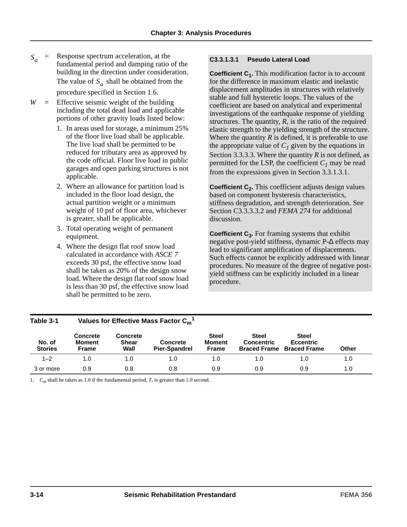
Chapter 3: Analysis Procedures
= Response spectrum acceleration, at the fundamental period and damping ratio of the building in the direction under consideration. The value of shall be obtained from the
procedure specified in Section 1.6.W = Effective seismic weight of the building
including the total dead load and applicable portions of other gravity loads listed below:1. In areas used for storage, a minimum 25%
of the floor live load shall be applicable. The live load shall be permitted to be reduced for tributary area as approved by the code official. Floor live load in public garages and open parking structures is not applicable.
2. Where an allowance for partition load is included in the floor load design, the actual partition weight or a minimum weight of 10 psf of floor area, whichever is greater, shall be applicable.
3. Total operating weight of permanent equipment.
4. Where the design flat roof snow load calculated in accordance with ASCE 7 exceeds 30 psf, the effective snow load shall be taken as 20% of the design snow load. Where the design flat roof snow load is less than 30 psf, the effective snow load shall be permitted to be zero.
Sa
Sa
C3.3.1.3.1 Pseudo Lateral Load
Coefficient C1. This modification factor is to account for the difference in maximum elastic and inelastic displacement amplitudes in structures with relatively stable and full hysteretic loops. The values of the coefficient are based on analytical and experimental investigations of the earthquake response of yielding structures. The quantity, R, is the ratio of the required elastic strength to the yielding strength of the structure. Where the quantity R is defined, it is preferable to use the appropriate value of C1 given by the equations in Section 3.3.3.3. Where the quantity R is not defined, as permitted for the LSP, the coefficient C1 may be read from the expressions given in Section 3.3.1.3.1.
Coefficient C2. This coefficient adjusts design values based on component hysteresis characteristics, stiffness degradation, and strength deterioration. See Section C3.3.3.3.2 and FEMA 274 for additional discussion.
Coefficient C3. For framing systems that exhibit negative post-yield stiffness, dynamic P-∆ effects may lead to significant amplification of displacements. Such effects cannot be explicitly addressed with linear procedures. No measure of the degree of negative post-yield stiffness can be explicitly included in a linear procedure.
Table 3-1 Values for Effective Mass Factor Cm1
No. of Stories
Concrete Moment Frame
Concrete ShearWall
Concrete Pier-Spandrel
Steel Moment Frame
Steel Concentric
Braced Frame
Steel Eccentric
Braced Frame Other
1–2 1.0 1.0 1.0 1.0 1.0 1.0 1.0
3 or more 0.9 0.8 0.8 0.9 0.9 0.9 1.0
1. Cm shall be taken as 1.0 if the fundamental period, T, is greater than 1.0 second.
3-14 Seismic Rehabilitation Prestandard FEMA 356

Chapter 3: Analysis Procedures
3.3.1.3.2 Vertical Distribution of Seismic Forces
The vertical distribution of the pseudo lateral load shall be as specified in this section for all buildings except unreinforced masonry buildings for which the pseudo lateral loads shall be permitted to be distributed in accordance with Section 3.3.1.3.5. The lateral load
applied at any floor level x shall be determined in accordance with Equation (3-11) and Equation (3-12):
(3-11)
(3-12)
where:
3.3.1.3.3 Horizontal Distribution of Seismic Forces
The seismic forces at each floor level of the building calculated using Equation (3-11) shall be distributed according to the distribution of mass at that floor level.
3.3.1.3.4 Diaphragms
Diaphragms shall be designed to resist the combined effects of the inertial force, , calculated in
accordance with Equation (3-13), and horizontal forces resulting from offsets in or changes in the stiffness of the vertical seismic framing elements above and below the diaphragm. Forces resulting from offsets in or changes in the stiffness of the vertical seismic framing elements shall be taken as the forces due to the pseudo lateral load of Equation (3-10) without reduction, unless smaller forces are justified by a limit-state or other rational analysis, and shall be added directly to the diaphragm inertial forces.
(3-13)
where:
The seismic load on each flexible diaphragm shall be distributed along the span of that diaphragm, proportional to its displaced shape.
Diaphragms receiving horizontal forces from discontinuous vertical elements shall be taken as force-controlled. Actions on other diaphragms shall be considered force- or deformation-controlled as specified for diaphragm components in Chapters 5 through 8.
= Vertical distribution factor
= 2.0 for seconds
= 1.0 for seconds
Linear interpolation shall be used to calculate values of for intermediate values of
= Pseudo lateral load from Equation (3-10)
= Portion of the total building weight W located on or assigned to floor level i
= Portion of the total building weight W located on or assigned to floor level x
= Height (in ft) from the base to floor level i
= Height (in ft) from the base to floor level x
Fx
Fx CvxV=
Cvx
wxhxk
wihik
i 1=
n
∑--------------------=
Cvx
k T 2.5≥
T 0.5≤
k T
V
wi
wx
hi
hx
= Total diaphragm inertial force at level x
= Lateral load applied at floor level i given by Equation (3-11)
= Portion of the effective seismic weight W located on or assigned to floor level i
= Portion of the effective seismic weight W located on or assigned to floor level x
Fpx
Fpx Fi
i x=
n
∑wx
wi
i x=
n
∑--------------=
Fpx
Fi
wi
wx
FEMA 356 Seismic Rehabilitation Prestandard 3-15
Chapter 3: Analysis Procedures
3.3.1.3.5 Distribution of Seismic Forces for Unreinforced Masonry Buildings with Flexible Diaphragms
For unreinforced masonry buildings with flexible diaphragms for which the fundamental period is calculated using Equation (3-9), it shall be permitted to calculate and distribute the pseudo lateral loads as follows:
1. For each span of the building and at each level, calculate period from Equation (3-9).
2. Using Equation (3-10), calculate pseudo lateral load for each span.
3. Apply the lateral loads calculated for all spans and calculate forces in vertical seismic-resisting elements using tributary loads.
4. Diaphragm forces for evaluation of diaphragms shall be determined from the results of step 3 above and distributed along the diaphragm span considering its deflected shape.
5. Diaphragm deflection shall not exceed 6 inches for this method of distribution of pseudo lateral loads to be applicable.
3.3.2 Linear Dynamic Procedure
3.3.2.1 Basis of the Procedure
If the Linear Dynamic Procedure (LDP) is selected for seismic analysis of the building, the design seismic forces, their distribution over the height of the building, and the corresponding internal forces and system displacements shall be determined using a linearly-elastic, dynamic analysis in compliance with the requirements of this section.
Buildings shall be modeled with linearly elastic stiffness and equivalent viscous damping values consistent with components responding at or near yield level, as defined in Section 2.4.4. Modeling and analysis procedures to calculate forces and deformations shall be in accordance with Section 3.3.2.2.
Results of the LDP shall be checked using the acceptance criteria of Section 3.4.2.
3.3.2.2 Modeling and Analysis Considerations
3.3.2.2.1 General
The ground motion characterized for dynamic analysis shall comply with the requirements of Section 3.3.2.2.2. The dynamic analysis shall be performed using the response spectrum method in accordance with Section 3.3.2.2.3 or the time-history method in accordance with Section 3.3.2.2.4.
3.3.2.2.2 Ground Motion Characterization
The horizontal ground motion shall be characterized for design by the requirements of Section 1.6 and shall be one of the following:
1. A response spectrum as specified in Section 1.6.1.5.
2. A site-specific response spectrum as specified in Section 1.6.2.1.
3. Ground acceleration time histories as specified in Section 1.6.2.2.
C3.3.2.1 Basis of the Procedure
Modal spectral analysis is carried out using linearly-elastic response spectra that are not modified to account for anticipated nonlinear response. As with the LSP, it is expected that the LDP will produce displacements that approximate maximum displacements expected during the design earthquake, but will produce internal forces that exceed those that would be obtained in a yielding building.
Calculated internal forces typically will exceed those that the building can sustain because of anticipated inelastic response of components and elements. These design forces are evaluated through the acceptance criteria of Section 3.4.2, which include modification factors and alternative analysis procedures to account for anticipated inelastic response demands and capacities.
3-16 Seismic Rehabilitation Prestandard FEMA 356

Chapter 3: Analysis Procedures
3.3.2.2.3 Response Spectrum Method
Dynamic analysis using the response spectrum method shall calculate peak modal responses for sufficient modes to capture at least 90% of the participating mass of the building in each of two orthogonal principal horizontal directions of the building. Modal damping ratios shall reflect the damping in the building at deformation levels less than the yield deformation.
Peak member forces, displacements, story forces, story shears, and base reactions for each mode of response shall be combined by either the SRSS (square root sum of squares) rule or the CQC (complete quadratic combination) rule.
Multidirectional seismic effects shall be considered in accordance with the requirements of Section 3.2.7.
3.3.2.2.4 Time History Method
Dynamic analysis using the time history method shall calculate building response at discrete time steps using discretized recorded or synthetic time histories as base motion. The damping matrix associated with the mathematical model shall reflect the damping in the building at deformation levels near the yield deformation.
Response parameters shall be calculated for each time history analysis. If three or more time history analyses are performed, the maximum response of the parameter of interest shall be used for design. If seven or more consistent pairs of horizontal ground motion records are used for time history analysis, use of the average of all responses of the parameter of interest shall be permitted for design.
Multidirectional seismic effects shall be considered in accordance with the requirements of Section 3.2.7. Alternatively, an analysis of a three-dimensional mathematical model using simultaneously imposed consistent pairs of earthquake ground motion records along each of the horizontal axes of the building shall be permitted.
3.3.2.3 Determination of Forces and Deformations
3.3.2.3.1 Modification of Demands
All forces and deformations calculated using either the Response Spectrum or Time History Analysis Methods shall be multiplied by the product of the modification factors C1, C2, and C3 defined in Section 3.3.1.3, and further modified to consider the effects of torsion in accordance with Section 3.2.2.2.
3.3.2.3.2 Diaphragms
Diaphragms shall be designed to resist simultaneously (1) the seismic forces calculated by the LDP, and (2) the horizontal forces resulting from offsets in, or changes in stiffness of, the vertical seismic framing elements above and below the diaphragm. The seismic forces calculated by the LDP shall be taken as not less than 85% of the forces calculated using Equation (3-13). Forces resulting from offsets in, or changes in stiffness of, the vertical seismic framing elements shall be taken to be equal to the elastic forces without reduction, unless smaller forces are justified by an approved rational analysis. Diaphragm actions need not be multiplied by the product of the modification factors C1, C2, and C3.
C3.3.2.2 Modeling and Analysis Considerations
The LDP includes two analysis methods, namely, the Response Spectrum Method and the Time History Method. The Response Spectrum Method uses peak modal responses calculated from dynamic analysis of a mathematical model. Only those modes contributing significantly to the response need to be considered. Modal responses are combined using rational methods to estimate total building response quantities. The Time History Method (also termed Response-History Analysis) involves a time-step-by-time-step evaluation of building response, using discretized recorded or synthetic earthquake records as base motion input. Pairs of ground motion records for simultaneous analysis along each horizontal axis of the building should be consistent. Consistent pairs are the orthogonal motions expected at a given site based on the same earthquake.
FEMA 356 Seismic Rehabilitation Prestandard 3-17
Chapter 3: Analysis Procedures
3.3.3 Nonlinear Static Procedure
3.3.3.1 Basis of the Procedure
If the Nonlinear Static Procedure (NSP) is selected for seismic analysis of the building, a mathematical model directly incorporating the nonlinear load-deformation characteristics of individual components and elements of the building shall be subjected to monotonically increasing lateral loads representing inertia forces in an earthquake until a target displacement is exceeded. Mathematical modeling and analysis procedures shall comply with the requirements of Section 3.3.3.2. The target displacement shall be calculated by the procedure in Section 3.3.3.3.
Calculated displacements and internal forces shall meet the acceptance criteria specified in Section 3.4.3.
3.3.3.2 Modeling and Analysis Considerations
3.3.3.2.1 General
The selection of a control node, the selection of lateral load patterns, the determination of the fundamental period, and analysis procedures shall comply with the requirements of this section.
The relation between base shear force and lateral displacement of the control node shall be established for control node displacements ranging between zero and 150% of the target displacement, δt.
The component gravity loads shall be included in the mathematical model for combination with lateral loads as specified in Section 3.2.8. The lateral loads shall be applied in both the positive and negative directions, and the maximum seismic effects shall be used for design.
The analysis model shall be discretized to represent the load-deformation response of each component along its length to identify locations of inelastic action.
All primary and secondary lateral-force-resisting elements shall be included in the model, as specified in Section 3.2.2.3.
The force-displacement behavior of all components shall be explicitly included in the model using full backbone curves that include strength degradation and residual strength, if any.
Alternatively, the use of a simplified NSP analysis shall be permitted. In a simplified NSP analysis only primary lateral force resisting elements are modeled, the force-displacement characteristics of such elements are bilinear, and the degrading portion of the backbone curve is not explicitly modeled. The simplified NSP analysis shall only be used in conjunction with the acceptance criteria of Section 3.4.3.2.2. Elements not meeting the acceptance criteria for primary components shall be designated as secondary, and removed from the mathematical model.
3.3.3.2.2 Control Node Displacement
The control node shall be located at the center of mass at the roof of a building. For buildings with a penthouse, the floor of the penthouse shall be regarded as the level of the control node. The displacement of the control node in the mathematical model shall be calculated for the specified lateral loads.
C3.3.3.1 Basis of the Procedure
The target displacement is intended to represent the maximum displacement likely to be experienced during the design earthquake. Because the mathematical model accounts directly for effects of material inelastic response, the calculated internal forces will be reasonable approximations of those expected during the design earthquake.
C3.3.3.2.1 General
When using the simplified NSP analysis, care should be taken to make sure that removal of degraded elements from the model does not result changes in the regularity of the structure that would significantly alter the dynamic response. In pushing with a static load pattern, the NSP does not capture changes in the dynamic characteristics of the structure as yielding and degradation take place.
In order to explicitly evaluate deformation demands on secondary elements that are to be excluded from the model, one might consider including them in the model, but with negligible stiffness, to obtain deformations demands without significantly affecting the overall response.
3-18 Seismic Rehabilitation Prestandard FEMA 356

Chapter 3: Analysis Procedures
3.3.3.2.3 Lateral Load Distribution
Lateral loads shall be applied to the mathematical model in proportion to the distribution of inertia forces in the plane of each floor diaphragm. For all analyses, at least two vertical distributions of lateral load shall be applied. One pattern shall be selected from each of the following two groups:
1. A modal pattern selected from one of the following:
1.1. A vertical distribution proportional to the values of Cvx given in Equation (3-12). Use of this distribution shall be permitted only when more than 75% of the total mass participates in the fundamental mode in the direction under consideration, and the uniform distribution is also used.
1.2. A vertical distribution proportional to the shape of the fundamental mode in the direction under consideration. Use of this distribution shall be permitted only when more than 75% of the total mass participates in this mode.
1.3. A vertical distribution proportional to the story shear distribution calculated by combining modal responses from a response spectrum analysis of the building, including sufficient modes to capture at least 90% of the total building mass, and using the appropriate ground motion spectrum.This distribution shall be used when the period of the fundamental mode exceeds 1.0 second.
2. A second pattern selected from one of the following:
2.1. A uniform distribution consisting of lateral forces at each level proportional to the total mass at each level.
2.2. An adaptive load distribution that changes as the structure is displaced. The adaptive load distribution shall be modified from the original load distribution using a procedure that considers the properties of the yielded structure.
3.3.3.2.4 Idealized Force-Displacement Curve
The nonlinear force-displacement relationship between base shear and displacement of the control node shall be replaced with an idealized relationship to calculate the effective lateral stiffness, , and effective yield
strength, , of the building as shown in Figure 3-1.
This relationship shall be bilinear, with initial slope Ke and post-yield slope α. Line segments on the idealized force-displacement curve shall be located using an iterative graphical procedure that approximately balances the area above and below the curve. The effective lateral stiffness, , shall be taken as the secant stiffness calculated at a base shear force equal to 60% of the effective yield strength of the structure. The post-yield slope, α, shall be determined by a line segment that passes through the actual curve at the calculated target displacement. The effective yield strength shall not be taken as greater than the maximum base shear force at any point along the actual curve.
C3.3.3.2.3 Lateral Load Distribution
The distribution of lateral inertial forces determines relative magnitudes of shears, moments, and deformations within the structure. The distribution of these forces will vary continuously during earthquake response as portions of the structure yield and stiffness characteristics change. The extremes of this distribution will depend on the severity of the earthquake shaking and the degree of nonlinear response of the structure. Use of more than one lateral load pattern is intended to bound the range of design actions that may occur during actual dynamic response.
In lieu of using the uniform distribution to bound the solution, changes in the distribution of lateral inertial forces can be investigated using adaptive load patterns that change as the structure is displaced to larger amplitudes. Procedures for developing adaptive load patterns include the use of story forces proportional to the deflected shape of the structure (Fajfar and Fischinger), the use of load patterns based on mode shapes derived from secant stiffnesses at each load step (Eberhard and Sozen), and the use of load patterns proportional to the story shear resistance at each step (Bracci et al.). Use of an adaptive load pattern will require more analysis effort, but may yield results that are more consistent with the characteristics of the building under consideration.
KeVy
Ke
FEMA 356 Seismic Rehabilitation Prestandard 3-19

Chapter 3: Analysis Procedures
3.3.3.2.5 Period Determination
The effective fundamental period in the direction under consideration shall be based on the idealized force-displacement curve defined in Section 3.3.3.2.4. The effective fundamental period, , shall be calculated in
accordance with Equation (3-14):
(3-14)
where:
3.3.3.2.6 Analysis of Mathematical Models
Separate mathematical models representing the framing along two orthogonal axes of the building shall be developed for two-dimensional analysis. A mathematical model representing the framing along two orthogonal axes of the building shall be developed for three-dimensional analysis.
The effects of horizontal torsion shall be evaluated in accordance with Section 3.2.2.2.
Independent analysis along each of the two orthogonal principal axes of the building shall be permitted unless concurrent evaluation of multidirectional effects is required by Section 3.2.7.
3.3.3.3 Determination of Forces and Deformations
3.3.3.3.1 General
For buildings with rigid diaphragms at each floor level, the target displacement, δt, shall be calculated in accordance with Equation (3-15) or by an approved procedure that accounts for the nonlinear response of the building.
For buildings with non-rigid diaphragms at each floor level, diaphragm flexibility shall be explicitly included in the model. The target displacement shall be calculated as specified for rigid diaphragms, except that it shall be amplified by the ratio of the maximum displacement at any point on the roof to the displacement at the center of mass of the roof (δmax/δcm). δmax and δcm shall be based on a response spectrum analysis of a three-dimensional model of the building. The target displacement so calculated shall be no less than that displacement given by Equation (3-15). No line of vertical seismic framing shall be evaluated for displacements smaller than the target displacement.
Figure 3-1 Idealized Force-Displacement Curves
Te
Te Ti
Ki
Ke------=
= Elastic fundamental period (in seconds) in the direction under consideration calculated by elastic dynamic analysis
= Elastic lateral stiffness of the building in the direction under consideration
= Effective lateral stiffness of the building in the direction under consideration
Ti
Ki
Ke
3-20 Seismic Rehabilitation Prestandard FEMA 356

Chapter 3: Analysis Procedures
Alternatively, for buildings with flexible diaphragms at each floor level, a target displacement shall be calculated for each line of vertical seismic framing. The target displacement for an individual line of vertical seismic framing shall be as specified for buildings with rigid diaphragms, except that the masses shall be assigned to each line on the basis of tributary area.
Forces and deformations corresponding to the control node displacement equaling or exceeding the target displacement shall comply with acceptance criteria of Section 3.4.3.
3.3.3.3.2 Target Displacement
The target displacement, δt, at each floor level shall be calculated in accordance with Equation (3-15) and as specified in Section 3.3.3.3.1.
g (3-15)
where:
The strength ratio R shall be calculated in accordance with Equation (3-16):
(3-16)
= Modification factor to relate spectral displacement of an equivalent SDOF system to the roof displacement of the building MDOF system calculated using one of the following procedures:• The first modal participation factor at the
level of the control node;• The modal participation factor at the level
of the control node calculated using a shape vector corresponding to the deflected shape of the building at the target displacement. This procedure shall be used if the adaptive load pattern defined in paragraph 2.2 of Section 3.3.3.2.3 is used; or
• The appropriate value from Table 3-2.= Modification factor to relate expected
maximum inelastic displacements to displacements calculated for linear elastic response:
= 1.0 for
= for
δt C0C1C2C3Sa
Te2
4π2---------=
C0
C1
Te TS≥
1.0 R 1–( )TS Te⁄+[ ] R⁄ Te TS<
but not greater than the values given in Section 3.3.1.3 nor less than 1.0.
= Effective fundamental period of the building in the direction under consideration, sec.
= Characteristic period of the response spectrum, defined as the period associated with the transition from the constant acceleration segment of the spectrum to the constant velocity segment of the spectrum per Sections 1.6.1.5 and 1.6.2.1.
= Ratio of elastic strength demand to calculated yield strength coefficient calculated by Equation (3-16).
= Modification factor to represent the effect of pinched hysteretic shape, stiffness degradation and strength deterioration on maximum displacement response. Values of for different framing systems and Structural Performance Levels shall be obtained from Table 3-3. Alternatively, use of C2 = 1.0 shall be permitted for nonlinear procedures.
= Modification factor to represent increased displacements due to dynamic P-∆ effects. For buildings with positive post-yield stiffness,
shall be set equal to 1.0. For buildings with negative post-yield stiffness, values of
shall be calculated using Equation (3-17) but not to exceed the values set forth in Section 3.3.1.3.
= Response spectrum acceleration, at the effective fundamental period and damping ratio of the building in the direction under consideration, g, as calculated in Sections 1.6.1.5 and 1.6.2.1.
g = acceleration of gravity
Te
TS
R
C2
C2
C3
C3
C3
Sa
RSa
Vy W⁄-------------- Cm⋅=
FEMA 356 Seismic Rehabilitation Prestandard 3-21
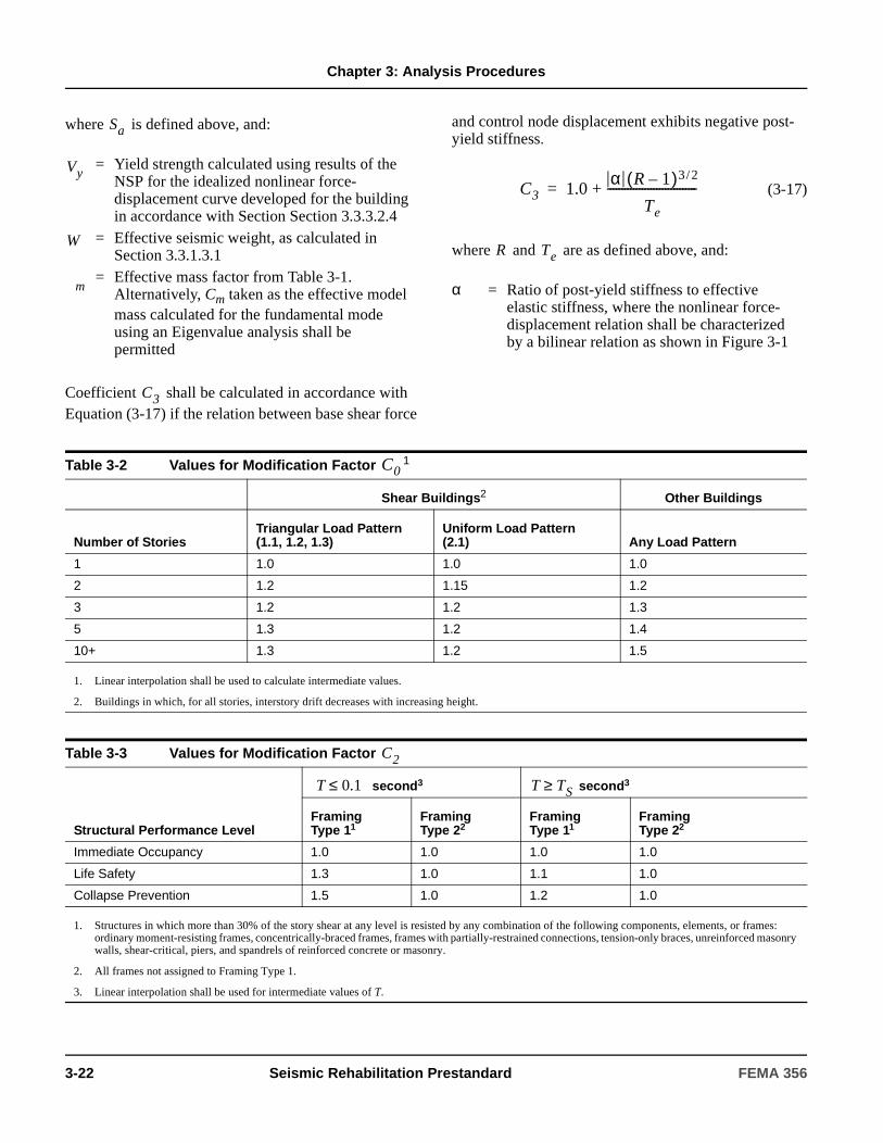
Chapter 3: Analysis Procedures
where is defined above, and:
Coefficient shall be calculated in accordance with Equation (3-17) if the relation between base shear force
and control node displacement exhibits negative post-yield stiffness.
(3-17)
where and are as defined above, and:
= Yield strength calculated using results of the NSP for the idealized nonlinear force-displacement curve developed for the building in accordance with Section Section 3.3.3.2.4
= Effective seismic weight, as calculated in Section 3.3.1.3.1
= Effective mass factor from Table 3-1. Alternatively, Cm taken as the effective model mass calculated for the fundamental mode using an Eigenvalue analysis shall be permitted
Sa
Vy
W
m
C3
α = Ratio of post-yield stiffness to effective elastic stiffness, where the nonlinear force- displacement relation shall be characterized by a bilinear relation as shown in Figure 3-1
C3 1.0α R 1–( )3 2/
Te
-------------------------------+=
R Te
Table 3-2 Values for Modification Factor 1
Shear Buildings2 Other Buildings
Number of StoriesTriangular Load Pattern (1.1, 1.2, 1.3)
Uniform Load Pattern(2.1) Any Load Pattern
1 1.0 1.0 1.0
2 1.2 1.15 1.2
3 1.2 1.2 1.3
5 1.3 1.2 1.4
10+ 1.3 1.2 1.5
1. Linear interpolation shall be used to calculate intermediate values.
2. Buildings in which, for all stories, interstory drift decreases with increasing height.
Table 3-3 Values for Modification Factor
Structural Performance Level
second3 second3
Framing Type 11
Framing Type 22
Framing Type 11
Framing Type 22
Immediate Occupancy 1.0 1.0 1.0 1.0
Life Safety 1.3 1.0 1.1 1.0
Collapse Prevention 1.5 1.0 1.2 1.0
1. Structures in which more than 30% of the story shear at any level is resisted by any combination of the following components, elements, or frames: ordinary moment-resisting frames, concentrically-braced frames, frames with partially-restrained connections, tension-only braces, unreinforced masonry walls, shear-critical, piers, and spandrels of reinforced concrete or masonry.
2. All frames not assigned to Framing Type 1.
3. Linear interpolation shall be used for intermediate values of T.
C0
C2
T 0.1≤ T TS≥
3-22 Seismic Rehabilitation Prestandard FEMA 356

Chapter 3: Analysis Procedures
C3.3.3.3.2 Target Displacement
Calculation Method. This standard presents the Coefficient Method for calculating target displacement. Other procedures can also be used. Section C3.3.3.3 of FEMA 274 presents additional background information on the Coefficient Method and another acceptable procedure referred to as the Capacity Spectrum Method.
Coefficient C0. This coefficient accounts for the difference between the roof displacement of an MDOF building and the displacement of the equivalent SDOF system. Using only the first mode shape (φ1) and elastic behavior, coefficient C0 is equal to the first-mode participation factor at the roof (control node) level. If the absolute value of the roof (control node) ordinate of each mode shape is set equal to unity, the value of coefficient C0 is equal to the first mode mass participation factor.
Explicit calculation of C0 using the actual deflected shape is more accurate and may be beneficial in terms of lower amplification of target displacement. The actual shape vector may take on any form, particularly since it is intended to simulate the time-varying deflection profile of the building responding inelastically to the ground motion. Based on past studies, the use of a shape vector corresponding to the deflected shape at the target displacement level may be more appropriate. This shape will likely be different from the elastic first-mode shape. While the use of such a deflected shape vector in the estimation of C0 is preferred, the choice of the elastic first-mode shape vector is a simpler alternative that takes into account at least the relative mass distribution over the height of the structure.
The use of the tabulated values, which are based on a straight-line vector with equal masses at each floor level, is approximate, particularly if masses vary much over the height of the building, and may be overly conservative.
Coefficient C1. This coefficient accounts for the observed difference in peak displacement response amplitude for nonlinear response as compared with linear response, as observed for buildings with relatively short initial vibration periods. For use with the NSP, it is recommended to calculate the value of this coefficient using the strength ratio, R, given by Equation (3-16). Additional discussion of this coefficient is in the commentary to Section 3.3.1.3.1.
Recent studies suggest that maximum elastic and inelastic displacement amplitudes may differ considerably if either the strength ratio R is large or the building is located in the near field of the causative fault. Specifically, the inelastic displacements will exceed the elastic displacement. If the strength ratio exceeds five, it is recommended that a displacement larger than the elastic displacement be used as the basis for calculating the target displacement.
Coefficient C2. If the hysteresis loops exhibit significant pinching or stiffness deterioration, the energy absorption and dissipation capacities decrease, and larger displacement excursions should be expected. This effect is important for short-period, low-strength structures with very pinched hysteresis loops. Framing Types 1 and 2 are introduced for the purpose of cataloguing systems prone to exhibit pinching and strength degradation—that is, Type 1. Type 2 systems are those not specifically identified as Type 1. Values for C2 are reduced for smaller levels of damage; that is, the values for C2 are smaller for the Immediate Occupancy Structural Performance Level (little to no damage) than for the Collapse Prevention Structural Performance Level (moderate to major damage). However, the selected performance level is not a direct measure of the extent of inelastic behavior that a building will experience, particularly in zones of moderate and low seismicity. If, for example, the structure meets a performance level superior to the selected performance level, use of a lower value of C2 corresponding to the actual performance level achieved would be justified. This may be done by interpolation between the C2 values specified for the performance levels above and below the level achieved. The values for C2 given in Table 3-3 are intended to account for both stiffness degradation and strength deterioration, and are based on judgment at the time this standard was written.
FEMA 356 Seismic Rehabilitation Prestandard 3-23
Chapter 3: Analysis Procedures
3.3.3.3.3 Modification of Demands
The target displacement shall be modified to consider the effects of horizontal torsion in accordance with Section 3.2.2.2.
3.3.3.3.4 Diaphragms
Diaphragms shall be designed to resist the combined effects of the horizontal forces resulting from offsets in, or changes in stiffness of, the vertical seismic framing elements above and below the diaphragm, and the diaphragm forces determined using either Section 3.3.1.3.4 or Section 3.3.2.3.2.
3.3.4 Nonlinear Dynamic Procedure
3.3.4.1 Basis of the Procedure
If the Nonlinear Dynamic Procedure (NDP) is selected for seismic analysis of the building, a mathematical model directly incorporating the nonlinear load-deformation characteristics of individual components and elements of the building shall be subjected to earthquake shaking represented by ground motion time histories in accordance with Section 1.6.2.2 to obtain forces and displacements.
Calculated displacements and internal forces shall be compared directly with acceptance criteria specified in Section 3.4.3.
3.3.4.2 Modeling and Analysis Considerations
3.3.4.2.1 General
The modeling and analysis requirements specified in Section 3.3.3.2 for the NSP shall apply to the NDP, excluding considerations of control node and target displacements.
3.3.4.2.2 Ground Motion Characterization
For the NDP, earthquake shaking shall be characterized by discretized recorded or synthetic earthquake records as base motion meeting the requirements of Section 1.6.2.2.
While single-degree-of-freedom systems with pinched hysteretic behavior do experience amplified displacements, some recent research has shown that the displacement response of multiple-degree-of-freedom building structures is not significantly affected by the pinched hysteretic behavior of individual elements. These new results are not yet entirely conclusive. At present, Table 3-3 has been retained in this standard, but the use of C2 = 1.0 is permitted.
Coefficient C3. P-∆ effects caused by gravity loads acting through the deformed configuration of a building will always result in an increase in lateral displacements. Static P-∆ effects can be captured using procedures set forth in Section 3.2.5. If P-∆ effects result in a negative post-yield stiffness in any one story, such effects may significantly increase the interstory drift and the target displacement. The degree by which dynamic P-∆ effects increase displacements depends on (1) the ratio α of the negative post-yield stiffness to the effective elastic stiffness, (2) the fundamental period of the building, (3) the strength ratio, (4) the hysteretic load-deformation relations for each story, (5) the frequency characteristics of the ground motion, and (6) the duration of the strong ground motion. Because of the number of parameters involved, it is difficult to capture dynamic P- ∆ effects with a single modification factor. Coefficient C3, calculated only for those buildings that exhibit negative post-yield stiffness, given by Equation (3-17), represents a substantial simplification and interpretation of much analysis data.
C3.3.4.1 Basis of the Procedure
The basis, modeling approaches, and acceptance criteria of the NDP are similar to those for the NSP. The main exception is that the response calculations are carried out using Time History Analysis. With the NDP, the design displacements are not established using a target displacement, but instead are determined directly through dynamic analysis using ground motion time histories. Calculated response can be highly sensitive to characteristics of individual ground motions; therefore, the analysis should be carried out with more than one ground motion record. Because the numerical model accounts directly for effects of material inelastic response, the calculated internal forces will be reasonable approximations of those expected during the design earthquake.
3-24 Seismic Rehabilitation Prestandard FEMA 356
Chapter 3: Analysis Procedures
3.3.4.2.3 Time History Method
For the NDP, Time History Analysis shall be performed using horizontal ground motion time histories prepared according to the requirements of Section 1.6.2.2.
Multidirectional seismic effects shall be accounted for in accordance with Section 3.2.7. Alternatively, an analysis of a three-dimensional mathematical model using simultaneously imposed consistent pairs of earthquake ground motion records along each of the horizontal axes of the building shall be permitted.
3.3.4.3 Determination of Forces and Deformations
Forces and deformations shall be determined in accordance with Section 3.3.2.2.4.
3.3.4.3.1 Modification of Demands
The effects of torsion shall be considered in accordance with Section 3.2.2.2.
3.3.4.3.2 Diaphragms
Diaphragms shall be designed to resist the effects of the seismic forces calculated by dynamic analysis including the effects of the horizontal forces resulting from offsets in, or changes in stiffness of, the vertical seismic framing elements above and below the diaphragm.
3.4 Acceptance Criteria
3.4.1 General Requirements
Components and elements analyzed using the linear procedures of Section 3.3.1 and Section 3.3.2 shall satisfy the requirements of Section 3.4.2. Components and elements analyzed using the nonlinear procedures of Section 3.3.3 and Section 3.3.4 shall satisfy the requirements of Section 3.4.3.
Prior to selecting component acceptance criteria, components shall be classified as primary or secondary, and actions shall be classified as deformation-controlled or force-controlled, as defined in Section 2.4.4.
Foundations shall satisfy the criteria specified in Chapter 4.
3.4.2 Linear Procedures
3.4.2.1 Design Forces and Deformations
Component design forces and deformations shall be calculated in accordance with linear analysis procedures of Sections 3.3.1 or 3.3.2.
3.4.2.1.1 Deformation-Controlled Actions
Deformation-controlled design actions shall be
calculated in accordance with Equation (3-18):
(3-18)
where:
3.4.2.1.2 Force-Controlled Actions
Force-controlled design actions, QUF, shall be calculated using one of the following methods:
1. QUF shall be taken as the maximum action that can be developed in a component based on a limit-state analysis considering the expected strength of the components delivering load to the component under consideration, or the maximum action developed in the component as limited by the nonlinear response of the building.
2. Alternatively, QUF shall be calculated in accordance with Equation (3-19).
= Action due to design earthquake loads calculated using forces and analysis models described in either Section 3.3.1 or Section 3.3.2
= Action due to design gravity loads as defined in Section 3.2.8
= Deformation-controlled design action due to gravity loads and earthquake loads
C3.4.2.1.1 Deformation-Controlled Actions
Because of possible anticipated nonlinear response of the structure, the design actions as represented by Equation (3-18) may exceed the actual strength of the component or element to resist these actions. The acceptance criteria of Section 3.4.2.2.1 take this overload into account through use of a factor, m, which is an indirect measure of the nonlinear deformation capacity of the component or element.
QUD
QUD QG QE±=
QE
QG
QUD
FEMA 356 Seismic Rehabilitation Prestandard 3-25

Chapter 3: Analysis Procedures
(3-19)
where:
3.4.2.2 Acceptance Criteria for Linear Procedures
3.4.2.2.1 Deformation-Controlled Actions
Deformation-controlled actions in primary and secondary components and elements shall satisfy Equation (3-20).
(3-20)
where:
QCE, the expected strength, shall be determined considering all coexisting actions on the component under the design loading condition by procedures specified in Chapters 4 through 8.
= Force-controlled design action due to gravity loads in combination with earthquake loads
= Force-delivery reduction factor, greater than or equal to 1.0, taken as the smallest DCR of the components in the load path delivering force to the component in question, calculated in accordance with Equation (2-1).Alternatively, values of J equal to 2.0 in Zones of High Seismicity, 1.5 in Zones of Moderate Seismicity, and 1.0 in Zones of Low Seismicity shall be permitted when not based on calculated DCRs. J shall be taken as 1.0 for the Immediate Occupancy Structural Performance Level. In any case where the forces contributing to QUF are delivered by components of the lateral force resisting system that remain elastic, J shall be taken as 1.0.
C3.4.2.1.2 Force-Controlled Actions
The basic approach for calculating force-controlled actions for design differs from that used for deformation-controlled actions because nonlinear deformations associated with forced-controlled actions are not permitted. Therefore, force demands for force-controlled actions should not exceed the force capacity (strength).
Ideally, an inelastic mechanism for the structure will be identified, and the force-controlled actions, QUF, for design will be determined by limit analysis using that mechanism. This approach will always produce a conservative estimate of the design actions, even if an incorrect mechanism is selected. Where it is not possible to use limit (or plastic) analysis, or in cases where design forces do not produce significant nonlinear response in the building, it is acceptable to determine the force-controlled actions for design using Equation (3-19).
QUF QG
QE
C1C2C3J-----------------------± =
QUF
J
Coefficients C1, C2, and C3 were introduced in Equation (3-10) to amplify the design base shear to achieve a better estimate of the maximum displacements expected for buildings responding in the inelastic range. Displacement amplifiers, C1, C2, and C3 are divided out of Equation (3-19) when seeking an estimate of the force level present in a component when the building is responding inelastically.
Since J is included for force-controlled actions, it may appear to be more advantageous to treat an action as force-controlled when m-factors are less than J. However, proper application of force-controlled criteria requires a limit state analysis of demand and lower bound calculation of capacity that will yield a safe result whether an action is treated as force- or deformation-controlled.
m = Component or element demand modifier (factor) to account for expected ductility associated with this action at the selected Structural Performance Level. m-factors are specified in Chapters 4 through 8
= Expected strength of the component or element at the deformation level under consideration for deformation-controlled actions
κ = Knowledge factor defined in Section 2.2.6.4
mκQCE QUD≥
QCE
3-26 Seismic Rehabilitation Prestandard FEMA 356

Chapter 3: Analysis Procedures
3.4.2.2.2 Force-Controlled Actions
Force-controlled actions in primary and secondary components and elements shall satisfy Equation (3-21):
(3-21)
where:
QCL, the lower-bound strength, shall be determined considering all coexisting actions on the component under the design loading condition by procedures specified in Chapters 5 through 8.
3.4.2.2.3 Verification of Design Assumptions
In addition to the requirements in Section 3.2.9, the following verification of design assumptions shall be made.
Where moments due to gravity loads in horizontally spanning primary components exceed 75% of the expected moment strength at any location, the possibility for inelastic flexural action at locations other than member ends shall be specifically investigated by comparing flexural actions with expected member strengths.
3.4.3 Nonlinear Procedures
3.4.3.1 Design Forces and Deformations
Component design forces and deformations shall be calculated in accordance with nonlinear analysis procedures of Sections 3.3.3 or 3.3.4.
3.4.3.2 Acceptance Criteria for Nonlinear Procedures
3.4.3.2.1 Deformation-Controlled Actions
Primary and secondary components shall have expected deformation capacities not less than maximum deformation demands calculated at the target displacement. Primary and secondary component demands shall be within the acceptance criteria for secondary components at the selected Structural Performance Level. Expected deformation capacities shall be determined considering all coexisting forces and deformations in accordance with Chapters 4 through 8.
The base shear at the target displacement, Vt, shall not be less than 80% of the effective yield strength of the structure, Vy, defined in Section 3.3.3.2.4.
Acceptance criteria for the simplified NSP analysis of Section 3.3.3.2.1 shall be as specified in Section 3.4.3.2.2.
3.4.3.2.2 Deformation-Controlled Actions for the Simplified Nonlinear Static Analysis
Primary and secondary components modeled using the alternative simplified NSP analysis of Section 3.3.3.2.1 shall meet the requirements of this section. Expected deformation capacities shall not be less than maximum deformation demands calculated at the target displacement. Primary component demands shall be within the acceptance criteria for primary components at the selected Structural Performance Level. Demands on other components shall be within the acceptance criteria for secondary components at the selected Structural Performance Level. Expected deformation capacities shall be determined considering all coexisting forces and deformations by procedures specified in Chapters 4 through 8.
= Lower-bound strength of a component or element at the deformation level under consideration for force-controlled actions
κQCL QUF≥
QCLC3.4.3.2.1 Deformation-Controlled Actions
When all components are explicitly modeled with full backbone curves, the NSP can be used to evaluate the full contribution of all components to the lateral force resistance of the structure as they degrade to residual strength values. When degradation is explicitly evaluated in the NSP, components can be relied upon for lateral-force resistance out to the secondary component limits of response. As components degrade, the post-yield slope of the force-displacement curve becomes negative, and the target displacement begins to grow. The procedure is self-limiting in that small negative post-yield slopes will result in large amplifications of the target displacement through the C3 coefficient, quickly causing nonconvergence of the solution. As an additional control on the extent of degradation, Vt is limited to not less than 80% of Vy.
FEMA 356 Seismic Rehabilitation Prestandard 3-27
Chapter 3: Analysis Procedures
3.4.3.2.3 Force-Controlled Actions
Primary and secondary components shall have lower-bound strengths not less than the maximum design forces. Lower-bound strengths shall be determined considering all coexisting forces and deformations by procedures specified in Chapters 4 through 8.
3.4.3.2.4 Verification of Design Assumptions
In addition to the requirements in Section 3.2.9, the following verification of design assumptions shall be made.
Flexural plastic hinges shall not form away from component ends unless they are explicitly accounted for in modeling and analysis.
C3.4.3.2.2 Deformation-Controlled Actions for the Simplified Nonlinear Static Analysis
In the simplified NSP analysis, primary components are not modeled with full backbone curves. Degradation cannot be explicitly evaluated and degraded elements cannot be reliably used to the secondary component limits of response. For this reason, the lateral-force-resistance of the structure consists of primary components measured against primary component acceptance criteria.
3-28 Seismic Rehabilitation Prestandard FEMA 356

4. Foundations and Geologic Site Hazards
4.1 ScopeThis chapter sets forth general requirements for consideration of foundation load-deformation characteristics, seismic rehabilitation of foundations, and mitigation of geologic site hazards in the Systematic Rehabilitation of buildings.
Section 4.2 specifies data collection for site characterization and defines geologic site hazards. Section 4.3 outlines procedures for mitigation of geologic site hazards. Section 4.4 provides soil strength and stiffness parameters for consideration of foundation load-deformation characteristics. Section 4.5 specifies seismic earth pressures on building walls. Section 4.6 specifies requirements for seismic rehabilitation of foundations.
4.2 Site CharacterizationSite characterization shall include collection of information on the building foundation as specified in Section 4.2.1, and on seismic geologic site hazards as specified in Section 4.2.2.
4.2.1 Foundation Information
Information on the foundation supporting the building to be rehabilitated, nearby foundation conditions, design foundation loads, and load-deformation characteristics of the foundation soils shall be obtained as specified in Sections 4.2.1.1 through 4.2.1.3.
4.2.1.1 Foundation Conditions
4.2.1.1.1 Structural Foundation Information
The following structural information shall be obtained for the foundation of the building to be rehabilitated:
1. Foundation type.
2. Foundation configuration, including dimensions, locations, depth of embedment of shallow foundations, pile tip elevations, and variations in cross-section along the length of pile or belled caissons.
3. Material composition and details of construction.
4.2.1.1.2 Subsurface Soil Conditions
The following information on subsurface soil conditions shall be obtained as required by the selected performance level:
C4.1 ScopeThis chapter provides geotechnical engineering provisions for building foundations and seismic-geologic site hazards. Acceptability of the behavior of the foundation system and foundation soils for a given performance level cannot be determined apart from the context of the behavior of the superstructure.
Geotechnical requirements for buildings that are suitable for Simplified Rehabilitation are included in Chapter 10. Structural engineering issues of foundation systems are discussed in the chapters on Steel and Cast Iron (Chapter 5), Concrete (Chapter 6), Masonry (Chapter 7), and Wood and Light Metal Framing (Chapter 8).
C4.2 Site CharacterizationThe guidance of the State Historic Preservation Officer should be obtained if historic or archeological resources are present at the site.
C4.2.1.1.1 Structural Foundation Information
Foundation types may consist of shallow isolated or continuous spread footings, mat foundations, deep foundations of driven piles, or cast-in-place concrete piers or drilled shafts of concrete.
Foundation material types include concrete, steel, and wood. Foundation installation methods include cast-in-place and open/closed-end driving.
With this minimum amount of information, presumptive or prescriptive procedures may be used to determine the ultimate bearing capacity of the foundations. However, additional information is required for site-specific assessments of foundation bearing capacity and stiffness. Acquiring this additional information involves determining unit weights, shear strength, friction angle, compressibility characteristics, soil moduli, and Poisson’s ratio.
FEMA 356 Seismic Rehabilitation Prestandard 4-1

Chapter 4: Foundations and Geologic
Site Hazards
1. For Collapse Prevention and Life Safety Performance Levels, the type, composition, consistency, relative density, and layering of soils shall be determined to a depth at which the stress imposed by the building is less than or equal to 10% of the building weight divided by the total foundation area. For buildings with friction piles, the depth so calculated shall be increased by two-thirds of the pile length. For end bearing piles, the depth of investigation shall be the pile length plus 10 feet.
2. The location of the water table and its seasonal fluctuations beneath the building shall be determined.
3. For enhanced rehabilitation objectives, the soil unit weight, γ; soil cohesion, c; soil friction angle, φ; soil compressibility characteristics, soil shear modulus, G; and Poisson’s ratio, ν, for each type, shall be determined.
4.2.1.2 Design Foundation Loads
Information on the design foundation loads shall be obtained including separate information on dead loads and live loads.
4.2.1.3 Load-Deformation Characteristics Under Seismic Loading
Load-deformation characteristics of foundations shall be obtained from geotechnical reports, or shall be determined in accordance with the requirements of Section 4.4.
4.2.2 Seismic Geologic Site Hazards
Seismic rehabilitation shall include an assessment of earthquake-induced hazards at the site due to fault rupture, liquefaction, differential compaction, landsliding, and an assessment of earthquake-induced flooding or inundation in accordance with Sections 4.2.2.1 through 4.2.2.5.
If the resulting ground movements cause unacceptable performance in the building for the selected performance level, then the hazards shall be mitigated in accordance with Section 4.3.
4.2.2.1 Fault Rupture
A geologic fault shall be defined as a plane or zone along which earth materials on opposite sides have moved differentially in response to tectonic forces.
Geologic site information shall be obtained to determine if an active geologic fault is present under the building foundation. If a fault is present, the following information shall be obtained:
C4.2.1.1.2 Subsurface Soil Conditions
Specific foundation information developed for an adjacent or nearby building may be useful if subsurface soils and ground water conditions in the site region are known to be uniform. However, less confidence will result if subsurface data are developed from anywhere but the site of the building being rehabilitated. Adjacent sites where construction has been done recently may provide a guide for evaluation of subsurface conditions at the site being considered.
Design drawings may indicate information regarding the allowable bearing capacity of the foundation elements. This information can be used directly in a presumptive or prescriptive evaluation of the foundation capacity. Construction records may also be available indicating ultimate pile capacities if load tests were performed. Information on the existing loads on the structure is relevant to determining the amount of overload that the foundations may be capable of resisting during an earthquake.
C4.2.1.3 Load-Deformation Characteristics Under Seismic Loading
Traditional geotechnical engineering treats load-deformation characteristics for long-term dead loads plus frequently applied live loads only. In most cases, long-term settlement governs foundation design. Short-term (earthquake) load-deformation characteristics have not traditionally been used for design; consequently, such relationships are not generally found in the geotechnical reports for existing buildings.
4-2 Seismic Rehabilitation Prestandard FEMA 356
Chapter 4: Foundations and Geologic
Site Hazards
1. The degree of activity based on the age of most recent movement.
2. The fault type; whether it is a strike-slip, normal-slip, reverse-slip, or thrust fault.
3. The sense of slip with respect to building geometry.
4. Magnitudes of vertical and/or horizontal displacements consistent with the selected earthquake hazard level.
5. The width and distribution of the fault-rupture zone.
4.2.2.2 Liquefaction
Liquefaction shall be defined as an earthquake-induced process in which saturated, loose, granular soils lose shear strength and liquefy as a result of an increase in pore-water pressure during earthquake shaking.
Subsurface soil and ground water information shall be obtained to determine if liquefiable materials are present under the building foundation. If liquefiable soils are present, the following information shall be obtained: soil type, soil density, depth to water table, ground surface slope, proximity of free-face conditions, and lateral and vertical differential displacements.
A site shall be regarded as free from liquefaction hazard if the site soils, or similar soils in the site vicinity, have not experienced historical liquefaction, and if any of the following criteria are met:
1. The geologic materials underlying the site are either bedrock or have a very low liquefaction susceptibility according to the relative susceptibility ratings based upon the type of deposit and geologic age of the deposit, as shown in Table 4-1.
2. The soils underlying the site are stiff clays or clayey silts.
3. The soils are not highly sensitive, based on local experience.
4. The soils are cohesionless with a minimum normalized Standard Penetration Test (SPT) resistance, N1 60, value of 30 blows/foot as defined in ASTM D1586-99, for depths below the ground water table, or with clay content greater than 20%.
5. The ground water table is at least 35 feet below the deepest foundation depth, or 50 feet below the ground surface, whichever is shallower, including considerations for seasonal and historic ground-water level rises, and any slopes or free-face conditions in the site vicinity do not extend below the ground water elevation at the site.
If a liquefaction hazard is determined to exist at the site, then a more detailed evaluation of potential ground movements due to liquefaction shall be performed using approved procedures.
C4.2.2.1 Fault Rupture
Buildings found to straddle active faults should be assessed to determine if any rehabilitation is warranted, possibly to reduce the collapse potential of the structure given the likely amount and direction of fault displacement.
FEMA 356 Seismic Rehabilitation Prestandard 4-3
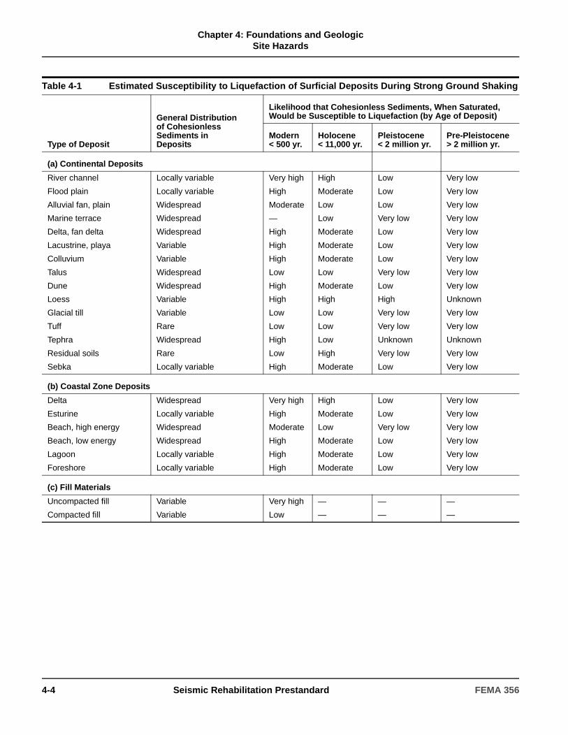
Chapter 4: Foundations and Geologic
Site Hazards
Table 4-1 Estimated Susceptibility to Liquefaction of Surficial Deposits During Strong Ground Shaking
Type of Deposit
General Distribution of CohesionlessSediments inDeposits
Likelihood that Cohesionless Sediments, When Saturated,Would be Susceptible to Liquefaction (by Age of Deposit)
Modern< 500 yr.
Holocene< 11,000 yr.
Pleistocene< 2 million yr.
Pre-Pleistocene> 2 million yr.
(a) Continental Deposits
River channel
Flood plain
Alluvial fan, plain
Marine terrace
Delta, fan delta
Lacustrine, playa
Colluvium
Talus
Dune
Loess
Glacial till
Tuff
Tephra
Residual soils
Sebka
Locally variable
Locally variable
Widespread
Widespread
Widespread
Variable
Variable
Widespread
Widespread
Variable
Variable
Rare
Widespread
Rare
Locally variable
Very high
High
Moderate
—
High
High
High
Low
High
High
Low
Low
High
Low
High
High
Moderate
Low
Low
Moderate
Moderate
Moderate
Low
Moderate
High
Low
Low
Low
High
Moderate
Low
Low
Low
Very low
Low
Low
Low
Very low
Low
High
Very low
Very low
Unknown
Very low
Low
Very low
Very low
Very low
Very low
Very low
Very low
Very low
Very low
Very low
Unknown
Very low
Very low
Unknown
Very low
Very low
(b) Coastal Zone Deposits
Delta
Esturine
Beach, high energy
Beach, low energy
Lagoon
Foreshore
Widespread
Locally variable
Widespread
Widespread
Locally variable
Locally variable
Very high
High
Moderate
High
High
High
High
Moderate
Low
Moderate
Moderate
Moderate
Low
Low
Very low
Low
Low
Low
Very low
Very low
Very low
Very low
Very low
Very low
(c) Fill Materials
Uncompacted fill
Compacted fill
Variable
Variable
Very high
Low
—
—
—
—
—
—
4-4 Seismic Rehabilitation Prestandard FEMA 356

Chapter 4: Foundations and Geologic
Site Hazards
C4.2.2.2 Liquefaction
Soil liquefaction is a phenomenon in which a soil below the ground-water table loses a substantial amount of strength due to strong earthquake ground shaking. Recently deposited (i.e., geologically young) and relatively loose natural soils and uncompacted or poorly compacted fill soils are potentially susceptible to liquefaction. Loose sands and silty sands are particularly susceptible; loose silts and gravels also have potential for liquefaction. Dense natural soils and well-compacted fills have low susceptibility to liquefaction. Clay soils are generally not susceptible, except for highly sensitive clays found in some geographic regions.
The following information may be necessary for evaluating the liquefaction potential of soils.
1. Soil type: Whether liquefiable soils—i.e., granular (sand, silty sand, nonplastic silt) soils—are present.
2. Soil density: Whether liquefiable soils are loose to medium dense.
3. Depth to water table: Whether liquefiable soils are saturated at any time during seasonal fluctuations of the water table.
4. Ground surface slope and proximity of free-face conditions: Whether liquefiable soils are at a gently sloping site or in the proximity of free-surface conditions.
5. Lateral and vertical differential displacement: Amount and direction at the building foundation should be calculated.
Seed-Idriss Procedure for Evaluating Liquefaction Potential The potential for liquefaction to occur may be assessed by a variety of available approaches (National Research Council). The most commonly utilized approach is the Seed-Idriss simplified empirical procedure—presented by Seed and Idriss (1971, 1982) and updated by Seed et al. (1985) and Seed and Harder (1990)—that utilizes SPT blow count data. Using SPT data to assess liquefaction potential due to an earthquake is considered a reasonable engineering approach (Seed and Idriss, 1982; Seed et al., 1985; National Research Council), because many of the factors affecting penetration resistance affect the liquefaction resistance of sandy soils in a similar way, and because these liquefaction potential evaluation procedures are based on actual performance of soil deposits during worldwide historical earthquakes. More guidance for evaluating liquefaction potential is contained in Section C4.2.2.2 of FEMA 274.
Evaluating Potential for Lateral Spreading. Lateral spreads are ground-failure phenomena that can occur on gently sloping ground underlain by liquefied soil. Earthquake ground shaking affects the stability of sloping ground containing liquefiable materials by seismic inertia forces within the slope and by shaking-induced strength reductions in the liquefiable materials. Temporary instability due to seismic inertia forces is manifested by lateral “downslope” movement that can potentially involve large land areas. For the duration of ground shaking associated with moderate to large earthquakes, there could be many such occurrences of temporary instability, producing an accumulation of “downslope” movement. The resulting movements can range from a few inches or less to tens of feet, and are characterized by breaking up of the ground and horizontal and vertical offsets.
FEMA 356 Seismic Rehabilitation Prestandard 4-5

Chapter 4: Foundations and Geologic
Site Hazards
Various relationships for estimating lateral spreading displacement have been proposed, including the Liquefaction Severity Index (LSI) by Youd and Perkins (1978), a relationship incorporating slope and liquefied soil thickness by Hamada et al. (1986), a modified LSI approach presented by Baziar et al. (1992), and a relationship by Bartlett and Youd (1992), in which they characterize displacement potential as a function of earthquake and local site characteristics (e.g., slope, liquefaction thickness, and grain size distribution). The relationship of Bartlett and Youd (1992), which is empirically based on analysis of case histories where lateral spreading did and did not occur, is relatively widely used, especially for initial assessments of the hazard. More site-specific analyses can also be made based on slope stability and deformation analysis procedures using undrained residual strengths for liquefied sand (Seed and Harder, 1990; Stark and Mesri, 1992), along with either Newmark-type simplified displacement analyses (Newmark, 1965; Franklin and Chang, 1977; Makdisi and Seed, 1978; Yegian et al., 1991) or more complex deformation analysis approaches.
Evaluating Potential for Flow Slides. Flow generally occurs in liquefied materials found on steeper slopes and may involve ground movements of hundreds of feet or more. As a result, flow slides can be the most catastrophic of the liquefaction-related ground-failure phenomena. Fortunately, flow slides occur much less commonly than lateral spreads. Whereas lateral spreading requires earthquake inertia forces to create instability for movement to occur, flow movements occur when the gravitational forces acting on a ground slope exceed the strength of the liquefied materials within the slope. The potential for flow sliding can be assessed by carrying out static slope stability analyses using undrained residual strengths for the liquefied materials.
Evaluating Potential for Bearing Capacity Failure. The occurrence of liquefaction in soils supporting foundations can result in bearing capacity failures and large plunging-type settlements. In fact, the buildup of pore water pressures in a soil to less than a complete liquefaction condition will still reduce soil strength and may threaten bearing capacity if the strength is reduced sufficiently.
The potential for bearing capacity failure beneath a spread footing depends on the depth of the liquefied (or partially liquefied) layer below the footing, the size of the footing, and the load. If lightly loaded small footings are located sufficiently above the depth of liquefied materials, bearing capacity failure may not occur. The foundation bearing capacity for a case where a footing is located some distance above a liquefied layer can be assessed by evaluating the strength of the liquefied (excess pore pressure ratio = 1.0), partially liquefied and nonliquefied strata, then applying bearing capacity formulations for layered systems (Meyerhof, 1974; Hanna and Meyerhof, 1980; Hanna, 1981). The capacity of friction pile or pier foundations can be similarly assessed, based on the strengths of the liquefied, partially liquefied, and nonliquefied strata penetrated by the foundations.
Evaluating Potential for Liquefaction-Induced Settlements. Following the occurrence of liquefaction, over time the excess pore water pressures built up in the soil will dissipate, drainage will occur, and the soil will densify, manifesting at the ground surface as settlement. Differential settlements occur due to lateral variations in soil stratigraphy and density. Typically, such settlements are much smaller and tend to be more uniform than those due to bearing capacity failure. They may range from a few inches to a few feet at the most where thick, loose soil deposits liquefy.
One approach to estimating the magnitude of such ground settlement, analogous to the Seed-Idriss simplified empirical procedure for liquefaction potential evaluation (i.e., using SPT blow count data and cyclic stress ratio), has been presented by Tokimatsu and Seed (1987). Relationships presented by Ishihara and Yoshimine (1992) are also available for assessing settlement.
Evaluating Increased Lateral Earth Pressures on Building Walls. Liquefaction of soils adjacent to building walls increases lateral earth pressures which can be approximated as a fluid pressure having a unit weight equal to the saturated unit weight of the soil plus the inertial forces on the soil equal to the hydrodynamic pressure.
4-6 Seismic Rehabilitation Prestandard FEMA 356
Chapter 4: Foundations and Geologic
Site Hazards
4.2.2.3 Differential Compaction
Differential compaction shall be defined as an earthquake-induced process in which foundation soils compact and the foundation settles in a nonuniform manner across a site.
Subsurface soil information shall be obtained to determine if soils susceptible to differential compaction are present under the building foundation.
A site shall be regarded as free of a differential compaction hazard if the soil conditions meet both of the following criteria:
1. Geologic materials below the ground water table do not pose a liquefaction hazard, based on the criteria in Section 4.2.2.2.
2. Geologic deposits above the ground water table are either Pleistocene in geologic age (older than 11,000 years), stiff clays or clayey silts, or cohesionless sands, silts, and gravels with a minimum (N I)60 of 20 blows/0.3 m (20 blows/foot).
If a differential compaction hazard is determined to exist at the site, then a more detailed evaluation shall be performed using approved procedures.
4.2.2.4 Landsliding
A landslide shall be defined as the down-slope mass movement of earth resulting from any cause. Subsurface soil information shall be obtained to determine if soils susceptible to a landslide that will cause differential movement of the building foundation are present at the site.
Slope stability shall be evaluated at sites with:
1. Existing slopes exceeding 18 degrees (three horizontal to one vertical).
2. Prior histories of instability (rotational or translational slides, or rock fall).
Use of pseudo-static analyses shall be permitted to determine slope stability if the soils are not susceptible to liquefaction based on Section 4.2.2.2 or otherwise expected to lose shear strength during deformation. If soils are susceptible to liquefaction based on Section 4.2.2.2 or otherwise expected to lose shear strength during deformation, dynamic analyses shall be performed to determine slope stability.
Evaluating Potential for Flotation of Buried Structures. A common phenomenon accompanying liquefaction is the flotation of tanks or structures that are embedded in liquefied soil. A building with a basement surrounded by liquefied soil can be susceptible to either flotation or bearing capacity failure, depending on the building weight and the structural continuity (i.e., whether the basement acts as an integral unit). The potential for flotation of a buried or embedded structure can be evaluated by comparing the total weight of the buried or embedded structure with the increased uplift forces occurring due to the buildup of liquefaction-induced pore water pressures.
C4.2.2.3 Differential Compaction
Differential compaction or densification of soils may accompany strong ground shaking. The resulting differential settlements can be damaging to structures. Types of soil susceptible to liquefaction (that is, relatively loose natural soils, or uncompacted or poorly compacted fill soils) are also susceptible to compaction. Compaction can occur in soils above and below the ground-water table.
Situations most susceptible to differential compaction include heavily graded areas where deep fills have been placed to create building sites for development. If the fills are not well compacted, they may be susceptible to significant settlements, and differential settlements may occur above variable depths of fill placed in canyons and near the transitions of cut and filled areas.
FEMA 356 Seismic Rehabilitation Prestandard 4-7

Chapter 4: Foundations and Geologic
Site Hazards
Pseudo-static analyses shall use a seismic coefficient equal to SXS /5, to approximate one-half the peak ground acceleration at the site associated with the selected Rehabilitation Objective. Sites with a static factor of safety equal to or greater than 1.0 shall be judged to have adequate stability, and require no further stability analysis.
A sliding-block displacement analysis shall be performed for sites with a static factor of safety of less than 1.0. The displacement analysis shall determine the magnitude of ground movement and its effect upon the performance of the structure.
In addition to the effects of landslides that directly undermine the building foundation, the effects of rock fall or slide debris from adjacent slopes shall be evaluated using approved procedures.
4.2.2.5 Flooding or Inundation
For seismic rehabilitation of buildings for performance levels higher than Life Safety, site information shall be obtained to determine if the following sources of earthquake-induced flooding or inundation are present:
1. Dams located upstream, subject to damage by earthquake shaking or fault rupture.
2. Pipelines, aqueducts, and water storage tanks located upstream, subject to damage by fault rupture, earthquake-induced landslides, or strong shaking.
3. Coastal areas within tsunami zones or areas adjacent to bays or lakes, subject to seiche waves.
4. Low-lying areas with shallow ground water, subject to regional subsidence and surface ponding of water, resulting in inundation of the site.
Damage to buildings from earthquake-induced flooding or inundation shall be evaluated for its effect upon the performance of the structure.
In addition to the effects of earthquake-induced flooding or inundation, scour of building foundation soils from swiftly flowing water shall be evaluated using approved procedures.
4.3 Mitigation of Seismic-Geologic Site Hazards
Mitigation of seismic-geologic hazards identified in Section 4.2 shall be accomplished through modification of the structure, foundation, soil conditions, or other approved methods.
C4.2.2.4 Landsliding
If no blocks of rock are present at the site but a cliff or steep slope is located nearby, then the likely performance of the cliff under earthquake loading should be evaluated. The earthquake loading condition for cliff performance must be compatible with the earthquake loading condition selected for the Rehabilitation Objective for the building.
Some sites may be exposed to hazards from major landslides moving onto the site from upslope, or retrogressive removal of support from downslope. Such conditions should be identified during site characterization, and may pose special challenges if adequate investigation requires access to adjacent property.
C4.3 Mitigation of Seismic-Geologic Site Hazards
Opportunities exist to improve seismic performance under the influence of some site hazards at reasonable cost; however, some site hazards may be so severe that they are economically impractical to include in risk-reduction measures. The discussions presented in this section are based on the concept that the extent of site hazards is discovered after the decision for seismic rehabilitation of a building has been made; however, the decision to rehabilitate a building and the selection of a Rehabilitation Objective may have been made with full knowledge that significant site hazards exist and must be mitigated as part of the rehabilitation.
Possible mitigation strategies for seismic geologic site hazards are presented in the following sections.
4-8 Seismic Rehabilitation Prestandard FEMA 356
Chapter 4: Foundations and Geologic
Site Hazards
1. Fault Rupture. If the structural performance of a building evaluated for the calculated ground movement due to fault rupture during earthquake fails to comply with the requirements for the selected performance level, mitigation schemes should be employed that include one or more of the following measures to achieve acceptable performance: stiffening of the structure and/or its foundation; strengthening of the structure and/or its foundation; and modifications to the structure and/or its foundation to distribute the effects of differential vertical movement over a greater horizontal distance to reduce angular distortion.
Large movements caused by fault rupture generally cannot be mitigated economically. If the structural consequences of the estimated horizontal and vertical displacements are unacceptable for any performance level, either the structure, its foundation, or both, might be stiffened or strengthened to reach acceptable performance. Measures are highly dependent on specific structural characteristics and inadequacies. Grade beams and reinforced slabs are effective in increasing resistance to horizontal displacement. Horizontal forces are sometimes limited by sliding friction capacity of spread footings or mats. Vertical displacements are similar in nature to those caused by long-term differential settlement.
2. Liquefaction. If the structural performance of a building evaluated for the calculated ground movement due to liquefaction during an earthquake fails to comply with the requirements for the selected performance level, then one or more of the following mitigation measures should be implemented to achieve acceptable performance.
2.1 Modification of the Structure. The structure should be strengthened to improve resistance against the predicted liquefaction-induced ground deformation.
This solution may be feasible for small ground deformations.
2.2 Modification of the Foundation. The foundation system should be modified to reduce or eliminate the differential foundation displacements by underpinning existing shallow foundations to achieve bearing on deeper, nonliquefiable strata or by stiffening a shallow foundation system by a system of grade beams between isolated footings, or any other approved method.
2.3 Modification of the Soil Conditions. One or more of the following ground improvement techniques should be implemented to reduce or eliminate the liquefaction under existing buildings: soil grouting (either throughout the entire liquefiable strata beneath a building, or locally beneath foundation elements); installation of drains; or installation of permanent dewatering systems.
Other types of ground improvement widely used for new construction are less applicable to existing buildings because of the effects of the procedures on the building. Thus, removal and replacement of liquefiable soil or in-place densification of liquefiable soil by various techniques are not applicable beneath an existing building.
2.4 Mitigation of the Lateral Spreading. Large soil volumes should be stabilized and/or buttressing structures should be constructed.
If the potential for significant liquefaction-induced lateral spreading movements exists at a site, then the mitigation of the liquefaction hazard may be more difficult. This is because the potential for lateral spreading movements beneath a building may depend on the behavior of the soil mass at distances well beyond the building as well as immediately beneath it.
3. Differential Compaction. If the structural performance of a building evaluated for the calculated differential compaction during earthquake fails to comply with the requirements for the selected performance level, then one or more mitigation measures similar to those recommended for liquefaction should be implemented to achieve acceptable performance.
4. Landslide. If the structural performance of a building evaluated for the calculated ground movement due to landslide during earthquake fails to comply with the requirements for the selected performance level, then one or more of the following mitigation measures should be implemented to achieve acceptable performance:
1. Regrading.
2. Drainage.
3. Buttressing.
FEMA 356 Seismic Rehabilitation Prestandard 4-9
Chapter 4: Foundations and Geologic
Site Hazards
4.4 Foundation Strength and Stiffness
Foundation strength and stiffness shall be determined in accordance with this section.
4. Structural Improvements:
a. Gravity walls.
b. Tieback/soil nail walls.
c. Mechanically stabilized earth walls.
d. Barriers for debris torrents or rock fall.
e. Building strengthening to resist deformation.
f. Grade beams.
g. Shear walls.
5. Soil Modification/Replacement:
a. Grouting.
b. Densification.
5. Flooding or Inundation. If the structural performance of a building evaluated for the effects of earthquake-induced flooding and inundation fails to comply with the requirements for the selected performance level, then one or more of the following mitigating measures should be implemented to achieve acceptable performance:
1. Improvement of nearby dam, pipeline, or aqueduct facilities independent of the rehabilitated building.
2. Diversion of anticipated peak flood flows.
3. Installation of pavement around the building to reduce scour.
4. Construction of sea wall or breakwater for tsunami or seiche protection.
C4.4 Foundation Strength and Stiffness
It is assumed that foundation soils are not susceptible to significant strength loss due to earthquake loading. In general, soils have considerable ductility unless they degrade significantly in stiffness and strength under cyclic loading. With this assumption, the provisions of this section provide an overview of the requirements and procedures for evaluating the ability of foundations to withstand the imposed seismic loads without excessive deformations.
The amount of acceptable deformations for foundations in such soils depends primarily on the effect of the deformation on the structure, which in turn depends on the desired Structural Performance Level. However, foundation yield associated with mobilization at upper bound expected capacity during earthquake loading may be accompanied by progressive permanent foundation settlement during continued cyclic loading, albeit in most cases this settlement probably would be less than a few inches. In general, if the real loads transmitted to the foundation during earthquake loading do not exceed upper bound expected soil capacities, it can be assumed that foundation deformations will be relatively small.
Parametric analyses to cover uncertainties in soil load-deformation characteristics are required. One alternative is to perform the NSP or NDP because the nonlinear load-deformation characteristics of the foundations can be directly incorporated in these analyses (Section 4.4.2). In static analyses, a somewhat conservative interpretation of the results is recommended because cyclic loading effects cannot be incorporated directly.
4-10 Seismic Rehabilitation Prestandard FEMA 356

Chapter 4: Foundations and Geologic
Site Hazards
4.4.1 Expected Capacities of Foundations
The expected capacity of foundation components shall be determined by presumptive, prescriptive, or site-specific methods as specified in Sections 4.4.1.1 through 4.4.1.3. Capacities shall be based on foundation information obtained as specified in Section 4.2.1.
4.4.1.1 Presumptive Capacities
4.4.1.1.1 Presumptive Capacities of Shallow Foundations
Calculation of presumptive expected capacities for spread footings and mats shall be permitted using the parameters specified in Table 4-2.
4.4.1.1.2 Presumptive Capacities of Deep Foundations
1. Capacities of Piles or Piers in Granular Soils
Calculation of presumptive expected capacities of piles or piers in granular soils shall be permitted using the procedure shown in Figure 4-1.
2. Capacities of Piles or Piers in Cohesive Soils
Calculation of presumptive expected capacities of piles or piers in cohesive soils shall be permitted using the procedure shown in Figure 4-2.
C4.4.1 Expected Capacities of Foundations
Design values recommended by geotechnical engineers are generally consistent with lower bound values. It is important to obtain information on the actual factor of safety applied to arrive at design values so that ultimate soil capacities are understood and expected values can be properly derived.
C4.4.1.1.2 Presumptive Capacities of Deep Foundations
The calculation procedures for presumptive expected capacities of piles or piers specified in this section are adapted from ATC-40 and NAVFAC (1986a and 1986b).
Table 4-2 Parameters for Calculating Presumptive Expected Foundation Load Capacities of Spread Footings and Mats
Class of Materials2
Vertical FoundationPressure3
Lbs/Sq. Ft. (qc)
Lateral Bearing Pressure
Lbs/Sq. Ft./Ft ofDepth Below
Natural Grade4
Lateral Sliding1
Coefficient5Resistance6 Lbs/Sq. Ft
Massive Crystalline Bedrock 8000 2400 0.80 —
Sedimentary and Foliated Rock 4000 800 0.70 —
Sandy Gravel and/or Gravel (GW and GP)
4000 400 0.70 —
Sand, Silty Sand, Clayey Sand, Silty Gravel, and Clayey Gravel (SW, SP, SM, SC, GM, and GC)
3000 300 0.50 —
Clay, Sandy Clay, Silty Clay, and Clayey Silt (CL, ML, MH, and CH)
20007 200 — 260
1. Lateral bearing and lateral sliding resistance shall be permitted to be combined.
2. For soil classifications OL, OH, and PT (i.e., organic clays and peat), a foundation investigation shall be required.
3. All values of expected bearing capacities are for footings having a minimum width of 12 inches and a minimum depth of 12 inches into natural grade. Except where Footnote 7 applies, an increase of 20% is allowed for each additional foot of width or depth to a maximum value of three times the designated value.
4. Shall be permitted to be increased by the amount of the designated value for each additional foot of depth to a maximum of 15 times the designated value.
5. Coefficient applied to the dead load.
6. Lateral sliding resistance value to be multiplied by the contact area. In no case shall the lateral sliding resistance exceed one-half of the dead load.
7. No increase for width shall be permitted.
FEMA 356 Seismic Rehabilitation Prestandard 4-11
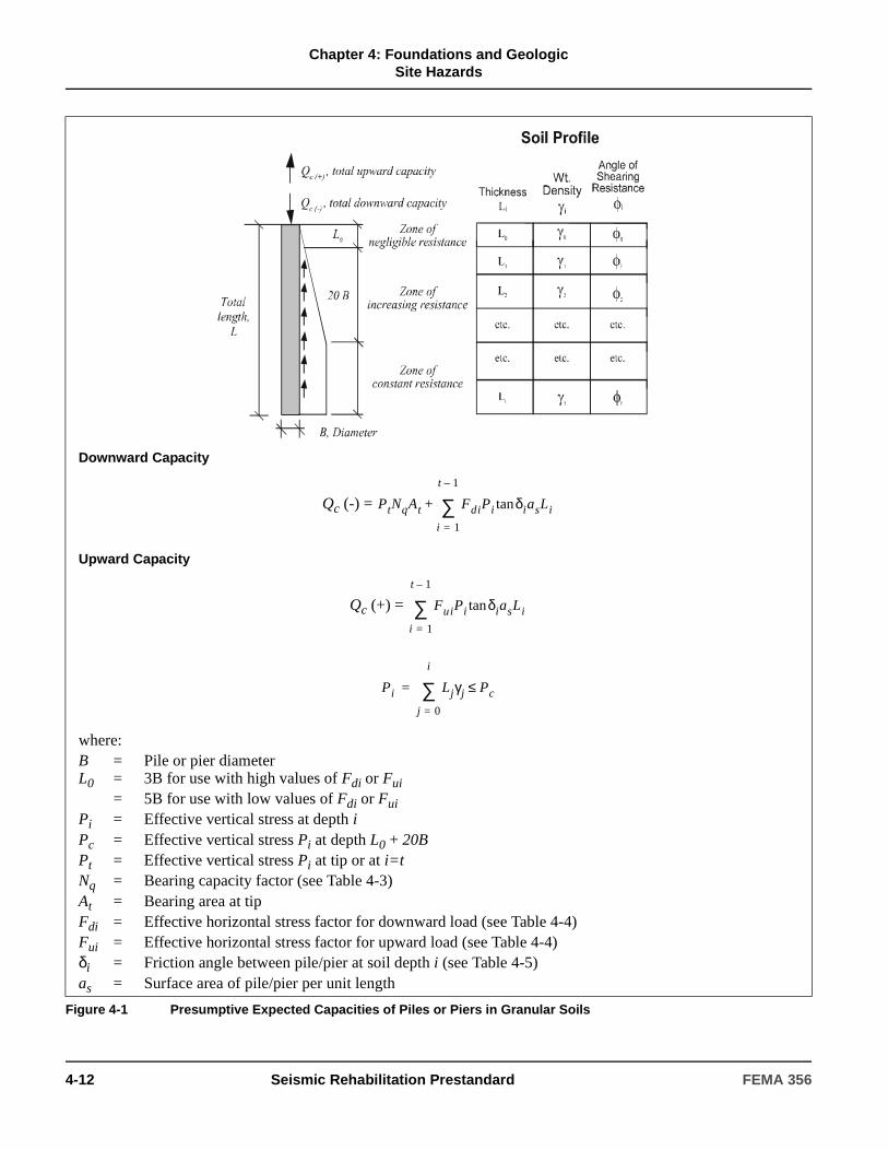
Chapter 4: Foundations and Geologic
Site Hazards
Downward Capacity
Qc (-) =
Upward Capacity
Qc (+) =
where:B = Pile or pier diameterL0 = 3B for use with high values of Fdi or Fui
= 5B for use with low values of Fdi or FuiPi = Effective vertical stress at depth iPc = Effective vertical stress Pi at depth L0 + 20BPt = Effective vertical stress Pi at tip or at i=tNq = Bearing capacity factor (see Table 4-3)At = Bearing area at tipFdi = Effective horizontal stress factor for downward load (see Table 4-4)Fui = Effective horizontal stress factor for upward load (see Table 4-4)δi = Friction angle between pile/pier at soil depth i (see Table 4-5)as = Surface area of pile/pier per unit length
Figure 4-1 Presumptive Expected Capacities of Piles or Piers in Granular Soils
PtNqAt FdiPi δiasLitan
i 1=
t 1–
∑+
FuiPi δiasLitan
i 1=
t 1–
∑
Pi Ljγj Pc≤j 0=
i
∑=
4-12 Seismic Rehabilitation Prestandard FEMA 356

Chapter 4: Foundations and Geologic
Site Hazards
Downward Capacity
Qc (-) =
Upward Capacity
Qc (+) =
where:B = Pile or pier diameterL0 = 4Bct = Cohesion strength of soil at tip (see Table 4-6)Nc = Bearing capacity factor = 9.0 for L > 4B
= 9L/4B for L < L0At = Bearing area at tipcai = Adhesion strength of soil (see Table 4-6) at depth ias = Surface area of pile/pier per unit length
Figure 4-2 Presumptive Expected Capacities of Piles or Piers in Cohesive Soils
ctNcAt caiasLi
i 1=
t
∑+
caiasLi
i 1=
t
∑
FEMA 356 Seismic Rehabilitation Prestandard 4-13
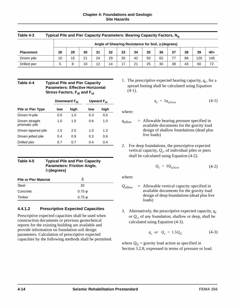
Chapter 4: Foundations and Geologic
Site Hazards
4.4.1.2 Prescriptive Expected Capacities
Prescriptive expected capacities shall be used when construction documents or previous geotechnical reports for the existing building are available and provide information on foundation soil design parameters. Calculation of prescriptive expected capacities by the following methods shall be permitted.
1. The prescriptive expected bearing capacity, qc, for a spread footing shall be calculated using Equation (4-1).
(4-1)
where:
2. For deep foundations, the prescriptive expected vertical capacity, Qc, of individual piles or piers shall be calculated using Equation (4-2).
(4-2)
where:
3. Alternatively, the prescriptive expected capacity, qc or Qc, of any foundation, shallow or deep, shall be calculated using Equation (4-3).
(4-3)
where QG = gravity load action as specified in Section 3.2.8, expressed in terms of pressure or load.
Table 4-3 Typical Pile and Pier Capacity Parameters: Bearing Capacity Factors, Nq
Placement
Angle of Shearing Resistance for Soil, φ (degrees)
26 28 30 31 32 33 34 35 36 37 38 39 40+
Driven pile 10 15 21 24 29 35 42 50 62 77 86 120 145
Drilled pier 5 8 10 12 14 17 21 25 30 38 43 60 72
Table 4-4 Typical Pile and Pier Capacity Parameters: Effective Horizontal Stress Factors, Fdi and Fui
Pile or Pier Type
Downward Fdi Upward Fui
low high low high
Driven H-pile 0.5 1.0 0.3 0.5
Driven straight prismatic pile
1.0 1.5 0.6 1.0
Driven tapered pile 1.5 2.0 1.0 1.3
Driven jetted pile 0.4 0.9 0.3 0.6
Drilled pier 0.7 0.7 0.4 0.4
Table 4-5 Typical Pile and Pier Capacity Parameters: Friction Angle, δ (degrees)
Pile or Pier Material δSteel 20
Concrete 0.75 φ
Timber 0.75 φ
qallow = Allowable bearing pressure specified in available documents for the gravity load design of shallow foundations (dead plus live loads)
Qallow = Allowable vertical capacity specified in available documents for the gravity load design of deep foundations (dead plus live loads)
qc 3qallow=
Qc 3Qallow=
qc or Qc 1.5QG=
4-14 Seismic Rehabilitation Prestandard FEMA 356

Chapter 4: Foundations and Geologic
Site Hazards
4.4.1.3 Site-Specific Capacities
For buildings where the methods specified in Sections 4.4.1.1 and 4.4.1.2 do not apply, a subsurface geotechnical investigation shall be conducted to determine expected ultimate foundation capacities based on the specific characteristics of the building site.
4.4.2 Load-Deformation Characteristics for Foundations
If building foundations are explicitly modeled in the mathematical model of the building, the load-deformation characteristics shall be calculated in accordance with Section 4.4.2.1 for shallow bearing foundations, Section 4.4.2.2 for pile foundations, and Section 4.4.2.3 for drilled shafts.
For explicit modeling of other types of foundations, load deformation characteristics shall be calculated by an approved method.
Nonlinear behavior of foundations shall be represented by an equivalent elasto-plastic load-deformation relationship unless another approved relationship is available.
Building analyses, including load-deformation characteristics of foundations, shall be bounded by upper and lower bound assumptions of stiffness and capacity as illustrated in Figure 4-3a and defined in this section. In lieu of an explicit evaluation of uncertainties of the foundation characteristics, it shall be permitted to
take the respective upper and lower bound stiffness and strength values as twice-and-one-half the values given in this section.
Table 4-6 Typical Pile and Pier Capacity Parameters: Cohesion, ct, and Adhesion, ca (psf)
Pile MaterialConsistency of Soil
(approximately STP blow count)
Cohesion, ct Adhesion, ca
low high low high
Timber and Concrete Very soft (<2) 0 250 0 250
Soft (2–4) 250 500 250 480
Medium stiff (4–8) 500 1000 480 750
Stiff (8–15) 1000 2000 750 950
Very stiff (>15) 2000 4000 950 1300
Steel Very soft (<2) 0 250 0 250
Soft (2–4) 250 500 250 460
Medium stiff (4–8) 500 1000 460 700
Stiff (8–15) 1000 2000 700 720
Very stiff (>15) 2000 4000 720 750
C4.4.2 Load-Deformation Characteristics for Foundations
Load-deformation characteristics are required where the effects of foundations are to be taken into account in Linear Static or Dynamic Procedures (LSP or LDP), Nonlinear Static (pushover) Procedures (NSP), or Nonlinear Dynamic (time-history) Procedures (NDP). Foundation load-deformation parameters characterized by both stiffness and capacity can have a significant effect on both structural response and load distribution among structural elements.
While it is recognized that the load-deformation behavior of foundations is nonlinear, an equivalent elasto-plastic representation of load-deformation behavior is recommended because of the difficulties in determining soil properties and the likely variability of soils supporting foundations. In addition, to allow for such variability or uncertainty, an upper and lower bound approach to defining stiffness and capacity is required to evaluate the sensitivity of the structural response to these parameters.
FEMA 356 Seismic Rehabilitation Prestandard 4-15
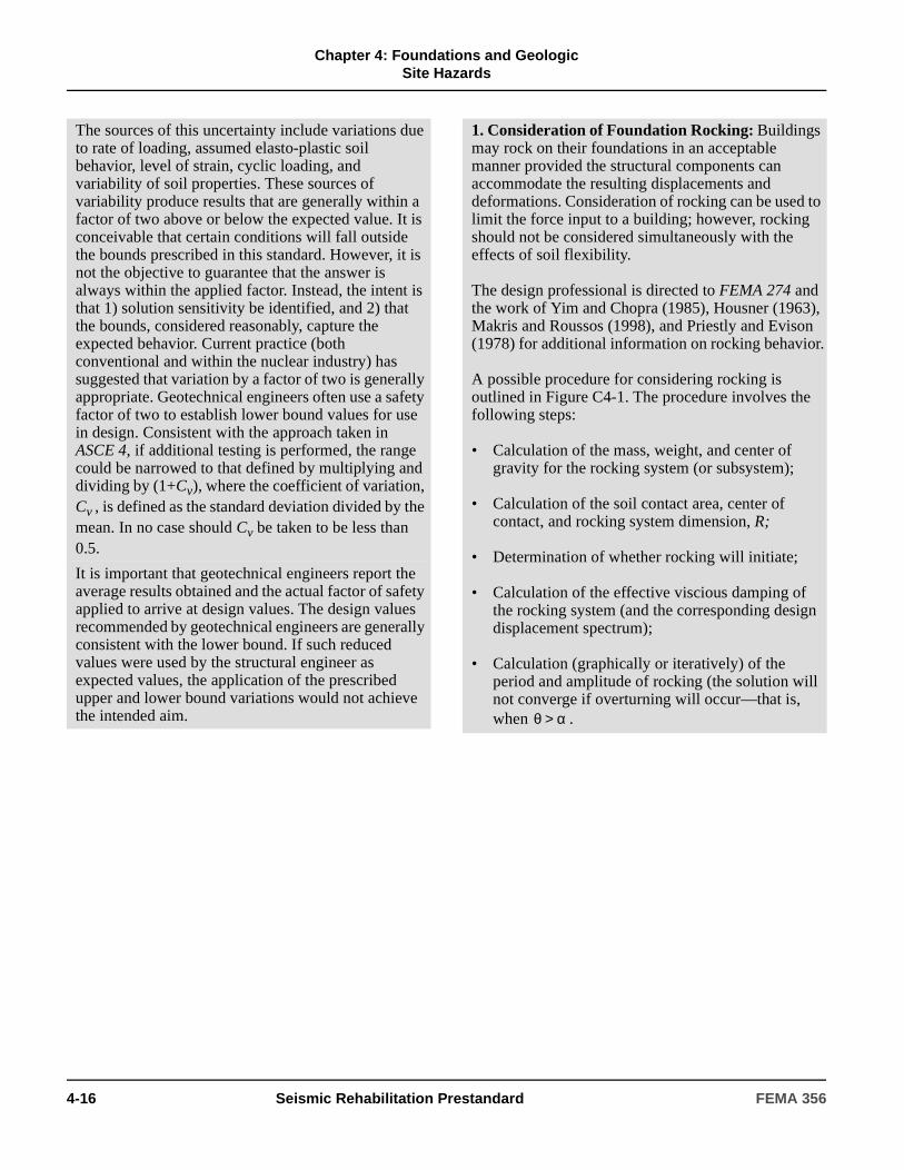
Chapter 4: Foundations and Geologic
Site Hazards
The sources of this uncertainty include variations due to rate of loading, assumed elasto-plastic soil behavior, level of strain, cyclic loading, and variability of soil properties. These sources of variability produce results that are generally within a factor of two above or below the expected value. It is conceivable that certain conditions will fall outside the bounds prescribed in this standard. However, it is not the objective to guarantee that the answer is always within the applied factor. Instead, the intent is that 1) solution sensitivity be identified, and 2) that the bounds, considered reasonably, capture the expected behavior. Current practice (both conventional and within the nuclear industry) has suggested that variation by a factor of two is generally appropriate. Geotechnical engineers often use a safety factor of two to establish lower bound values for use in design. Consistent with the approach taken in ASCE 4, if additional testing is performed, the range could be narrowed to that defined by multiplying and dividing by (1+Cv), where the coefficient of variation, Cv , is defined as the standard deviation divided by the mean. In no case should Cv be taken to be less than 0.5.
It is important that geotechnical engineers report the average results obtained and the actual factor of safety applied to arrive at design values. The design values recommended by geotechnical engineers are generally consistent with the lower bound. If such reduced values were used by the structural engineer as expected values, the application of the prescribed upper and lower bound variations would not achieve the intended aim.
1. Consideration of Foundation Rocking: Buildings may rock on their foundations in an acceptable manner provided the structural components can accommodate the resulting displacements and deformations. Consideration of rocking can be used to limit the force input to a building; however, rocking should not be considered simultaneously with the effects of soil flexibility.
The design professional is directed to FEMA 274 and the work of Yim and Chopra (1985), Housner (1963), Makris and Roussos (1998), and Priestly and Evison (1978) for additional information on rocking behavior.
A possible procedure for considering rocking is outlined in Figure C4-1. The procedure involves the following steps:
• Calculation of the mass, weight, and center of gravity for the rocking system (or subsystem);
• Calculation of the soil contact area, center of contact, and rocking system dimension, R;
• Determination of whether rocking will initiate;
• Calculation of the effective viscious damping of the rocking system (and the corresponding design displacement spectrum);
• Calculation (graphically or iteratively) of the period and amplitude of rocking (the solution will not converge if overturning will occur—that is, when .θ α>
4-16 Seismic Rehabilitation Prestandard FEMA 356
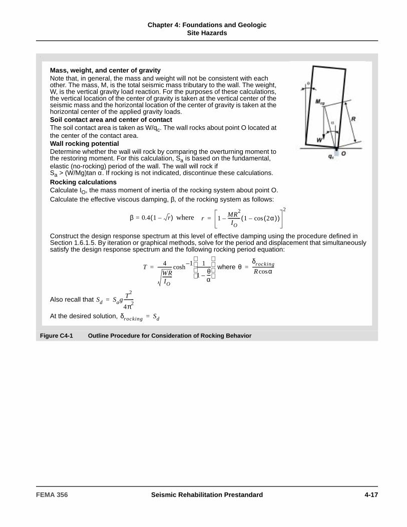
Chapter 4: Foundations and Geologic
Site Hazards
,
Figure C4-1 Outline Procedure for Consideration of Rocking Behavior
Mass, weight, and center of gravityNote that, in general, the mass and weight will not be consistent with each other. The mass, M, is the total seismic mass tributary to the wall. The weight, W, is the vertical gravity load reaction. For the purposes of these calculations, the vertical location of the center of gravity is taken at the vertical center of the seismic mass and the horizontal location of the center of gravity is taken at the horizontal center of the applied gravity loads.Soil contact area and center of contactThe soil contact area is taken as W/qc. The wall rocks about point O located at the center of the contact area.Wall rocking potentialDetermine whether the wall will rock by comparing the overturning moment to the restoring moment. For this calculation, Sa is based on the fundamental, elastic (no-rocking) period of the wall. The wall will rock if Sa > (W/Mg)tan α. If rocking is not indicated, discontinue these calculations.Rocking calculationsCalculate IO, the mass moment of inertia of the rocking system about point O.Calculate the effective viscous damping, β, of the rocking system as follows:
where
Construct the design response spectrum at this level of effective damping using the procedure defined in Section 1.6.1.5. By iteration or graphical methods, solve for the period and displacement that simultaneously satisfy the design response spectrum and the following rocking period equation:
where
Also recall that
At the desired solution,
β 0.4= 1 r–( ) r 1MR
2
IO----------- 1 2α( )cos–( )–
2
=
T4
WRIO
---------
------------- 1–cosh
1
1θα---–
-------------
= θδrocking
R αcos--------------------=
Sd SagT
2
4π2---------=
δrocking Sd=
FEMA 356 Seismic Rehabilitation Prestandard 4-17

Chapter 4: Foundations and Geologic
Site Hazards
4.4.2.1 Shallow Bearing Foundations
4.4.2.1.1 Stiffness Parameters
The initial shear modulus, Go, shall be calculated in accordance with Equation (4-4) or (4-5) where vs is the shear wave velocity at low strains, γ is the weight density of the soil, and g is the acceleration due to gravity.
(4-4)
(4-5)
where:
Go in Equation (4-5) is expressed in pounds per square
foot, as is .
The effective shear modulus, G, shall be calculated in accordance with Table 4-7.
Based on relative stiffnesses of the foundation structure and the supporting soil, the foundation stiffness shall be calculated using one of the following three methods.
= Standard Penetration Test blow count normalized for an effective stress of 1.0 ton per square foot confining pressure and corrected to an equivalent hammer energy efficiency of 60%
= Effective vertical stress in psf
=
γt = Total unit weight of soil
γw = Unit weight of water
d = Depth to sampledw = Depth to ground-water level
Go
γvs2
g--------=
Go 20 000 N1( )601 3⁄ σ ′o,≅
N1( )60
σ ′o
σ ′o γtd γw d dw–( )–
σ ′o
Table 4-7 Effective Shear Modulus Ratio(G/G0)
Site Class
Effective Peak Acceleration, SXS /2.5
SXS /2.5=0
SXS /2.5=0.1
SXS /2.5=0.4
SXS /2.5=0.8
A 1.00 1.00 1.00 1.00
B 1.00 1.00 0.95 0.90
C 1.00 0.95 0.75 0.60
D 1.00 0.90 0.50 0.10
E 1.00 0.60 0.05 *
F * * * *
Note: Use straight-line interpolation for intermediate values of SXS/2.5.
* Site-specific geotechnical investigation and dynamic site response analyses shall be performed.
C4.4.2.1.1 Stiffness Parameters
Table 4-7 is consistent with the site classification Tables 1-4 and 1-5 in that the layout and level of complexity is identical, and the indication of problem soils that require site-specific investigation (Site Class F) is consistent. The following observations on the relationship between shear modulus reduction and peak ground acceleration can be made:
1. As the peak ground acceleration approaches zero, the modulus reduction factor approaches unity,
2. Modulus reduction effects are significantly more pronounced for softer soils, and
3. The modulus reduction factors given in both FEMA 273 and the FEMA 302 NEHRP Recommended Provisions overestimate the modulus reduction effects for Site Classes A, B, and C.
4-18 Seismic Rehabilitation Prestandard FEMA 356

Chapter 4: Foundations and Geologic
Site Hazards
4.4.2.1.2 Method 1
For shallow bearing footings that are rigid with respect to the supporting soil, an uncoupled spring model, as shown in Figure 4-3(b), shall represent the foundation stiffness.
The equivalent spring constants shall be calculated as specified in Figure 4-4.
The shears and moments in foundation elements are conservative when such elements are considered rigid. However, soil pressures may be significantly underestimated when foundation flexibility is ignored. The flexibility and nonlinear response of soil and of foundation structures should be considered when the results would change.
For beams on elastic supports (for instance, strip footings and grade beams) with a point load at midspan, the beam may be considered rigid when:
(C4-1)
The above equation is generally consistent with traditional beam-on-elastic foundation limits (NAVFAC, 1986b; Bowles, 1988). The resulting soil bearing pressures are within 3% of the results, including foundation flexibility.
For rectangular plates (with plan dimensions L and B, and thickness t, and mechanical properties Ef and vf) on elastic supports (for instance, mat foundations or isolated footings) subjected to a point load in the center, the foundation may be considered rigid when:
(C4-2)where:
(C4-3)
The above equation is based on Timoshenko’s solutions for plates on elastic foundations (Timoshenko, 1959). The general solution has been simplified by restriction to a center load. Only the first five values of m and n (in the infinite series) are required to achieve reasonable accuracy.
EI
L4
------ 23---ksvB>
4ksv
m 1=
5
∑sin
2 m π⋅2
------------ sin
2 n π⋅2
----------
π4Df
m2
L2
------ n2
B2
------+ 2
ksv+
-------------------------------------------------------------- 0.03<n 1=
5
∑
Df
Ef t3
12 1 νf–( ) 2------------------------------=
Figure 4-3 (a) Idealized Elasto-Plastic Load-Deformation Behavior for Soils(b) Uncoupled Spring Model for Rigid Footings
FEMA 356 Seismic Rehabilitation Prestandard 4-19
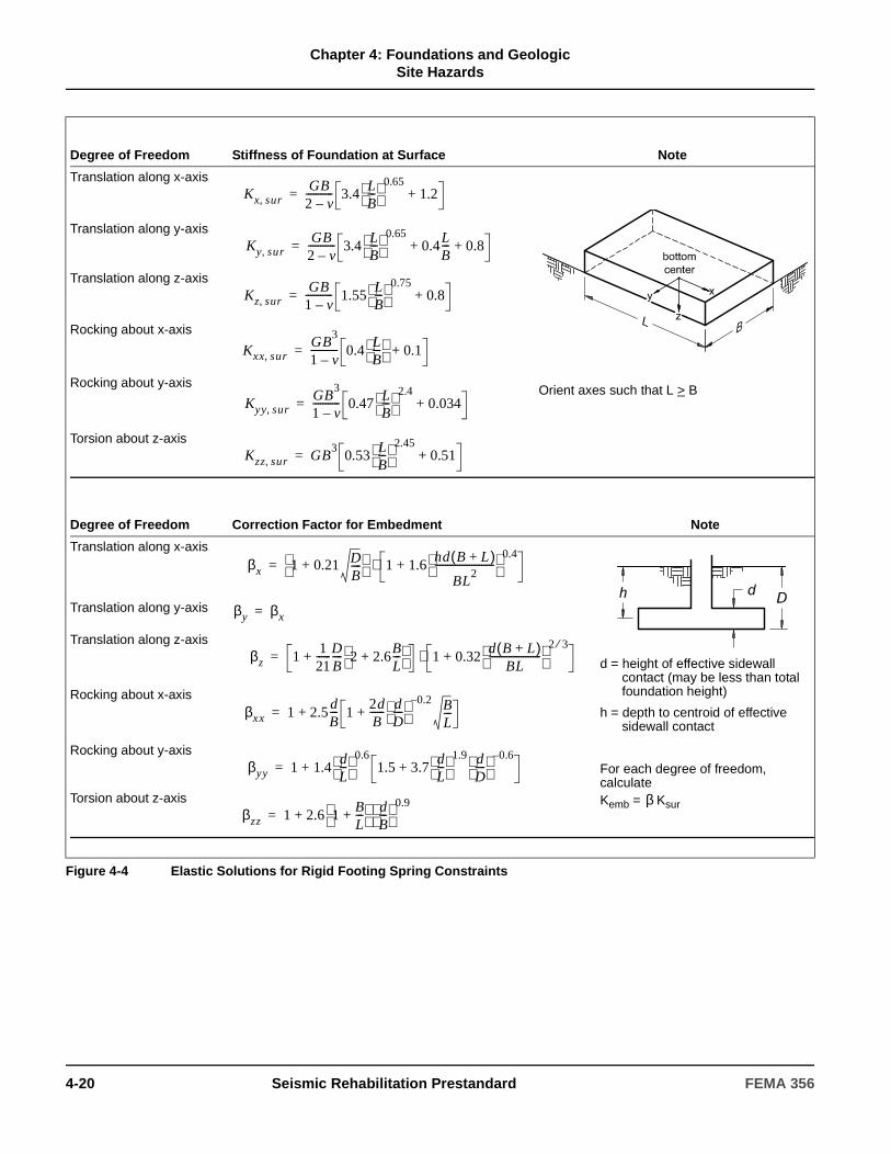
Chapter 4: Foundations and Geologic
Site Hazards
Figure 4-4 Elastic Solutions for Rigid Footing Spring Constraints
Degree of Freedom Stiffness of Foundation at Surface Note
Translation along x-axis
Orient axes such that L > B
Translation along y-axis
Translation along z-axis
Rocking about x-axis
Rocking about y-axis
Torsion about z-axis
Kx sur,GB
2 v–----------- 3.4
LB---
0.651.2+=
Ky sur,GB
2 v–----------- 3.4
LB---
0.650.4
LB--- 0.8+ +=
Kz sur,GB
1 v–----------- 1.55
LB---
0.750.8+=
Kxx sur,GB
3
1 v–----------- 0.4
LB---
0.1+=
Kyy sur,GB
3
1 v–----------- 0.47
LB---
2.40.034+=
Kzz sur, GB3
0.53LB---
2.450.51+=
Degree of Freedom Correction Factor for Embedment Note
Translation along x-axis
d = height of effective sidewall contact (may be less than total foundation height)
h = depth to centroid of effective sidewall contact
For each degree of freedom, calculate Kemb = Ksur
Translation along y-axis
Translation along z-axis
Rocking about x-axis
Rocking about y-axis
Torsion about z-axis
βx 1 0.21 DB----+
1 1.6hd B L+( )
BL2
------------------------ 0.4
+⋅=
β
βy βx=
βz 11
21------D
B---- 2 2.6
BL---+
+ 1 0.32d B L+( )
BL---------------------
2 3⁄+⋅=
βxx 1 2.5dB--- 1
2dB------ d
D----
0.2– BL---++=
βyy 1 1.4dL---
0.61.5 3.7
dL---
1.9 dD----
0.6–++=
βzz 1 2.6 1BL---+
dB---
0.9+=
4-20 Seismic Rehabilitation Prestandard FEMA 356
Chapter 4: Foundations and Geologic
Site Hazards
C4.4.2.1.2 Method 1
Researchers have developed spring stiffness solutions that are applicable to any solid basemat shape on the surface of, or partially or fully embedded in, a homogeneous halfspace (Gazetas). Rectangular foundations are most common in buildings. Therefore, the general spring stiffness solutions were adapted to the general rectangular foundation problem, which includes rectangular strip footings.
Using Figure 4-4, a two step calculation process is required. First, the stiffness terms are calculated for a foundation at the surface. Then, an embedment correction factor is calculated for each stiffness term. The stiffness of the embedded foundation is the product of these two terms. Figure C4-2 illustrates the effects of foundation aspect ratio and embedment.
According to Gazetas, the height of effective sidewall contact, d, should be taken as the average height of the sidewall that is in good contact with the surrounding soil. It should, in general, be smaller than the nominal height of contact to account for such phenomena as slippage and separation that may occur near the ground surface. Note that d will not necessarily attain a single value for all modes of oscillation. When d is taken larger than zero, the resulting stiffness includes sidewall friction and passive pressure contributions
Although frequency-dependent solutions are available, results are reasonably insensitive to loading frequencies within the range of parameters of interest for buildings subjected to earthquakes. It is sufficient to use static stiffnesses as representative of repeated loading conditions. Other formulations incorporating a wider range of variables may be found in Gazetas and Lam, et al.
FEMA 356 Seismic Rehabilitation Prestandard 4-21
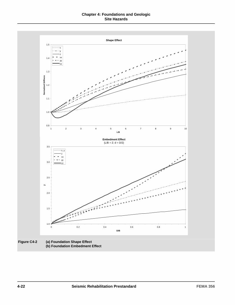
Chapter 4: Foundations and Geologic
Site Hazards
Figure C4-2 (a) Foundation Shape Effect(b) Foundation Embedment Effect
Embedment Effect(L/B = 2; d = D/2)
1.0
1.5
2.0
2.5
3.0
3.5
0 0.2 0.4 0.6 0.8 1
D/B
β
x, y
z
xx
yy
zz
Shape Effect
0.9
1.0
1.1
1.2
1.3
1.4
1.5
1 2 3 4 5 6 7 8 9 10
L/B
No
rmal
ized
Sti
ffn
ess
x
y
z
xx
yy
zz
4-22 Seismic Rehabilitation Prestandard FEMA 356
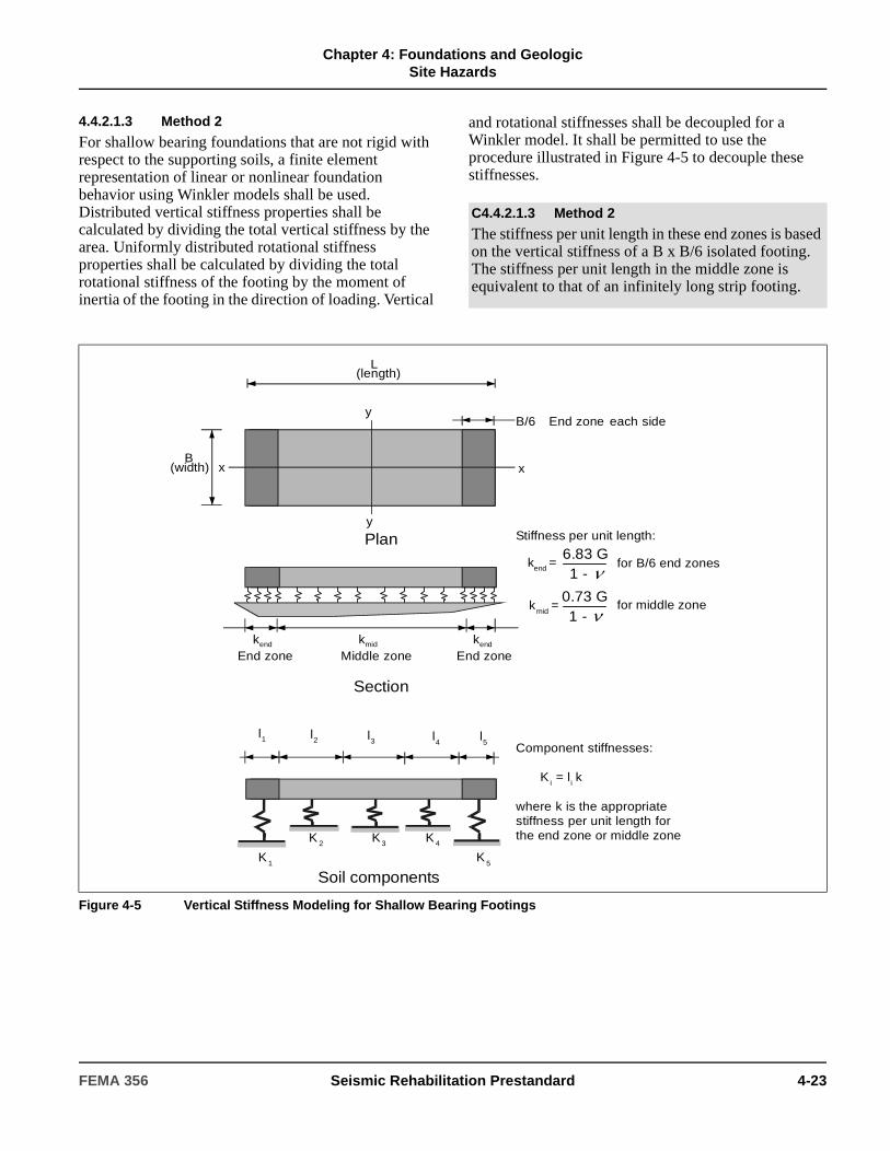
Chapter 4: Foundations and Geologic
Site Hazards
4.4.2.1.3 Method 2
For shallow bearing foundations that are not rigid with respect to the supporting soils, a finite element representation of linear or nonlinear foundation behavior using Winkler models shall be used. Distributed vertical stiffness properties shall be calculated by dividing the total vertical stiffness by the area. Uniformly distributed rotational stiffness properties shall be calculated by dividing the total rotational stiffness of the footing by the moment of inertia of the footing in the direction of loading. Vertical
and rotational stiffnesses shall be decoupled for a Winkler model. It shall be permitted to use the procedure illustrated in Figure 4-5 to decouple these stiffnesses.
C4.4.2.1.3 Method 2
The stiffness per unit length in these end zones is based on the vertical stiffness of a B x B/6 isolated footing. The stiffness per unit length in the middle zone is equivalent to that of an infinitely long strip footing.
Figure 4-5 Vertical Stiffness Modeling for Shallow Bearing Footings
y
x
y
x
Plan
L(length)
B(width)
B/6 End zone each side
Soil componentsK
1
l1 l5
l4
l3l2
K5
K4K3K 2
Component stiffnesses:
Ki = li k
where k is the appropriatestiffness per unit length forthe end zone or middle zone
Stiffness per unit length:
kend = for B/6 end zones
kmid
= for middle zone
Section
kmid kendkend
End zone Middle zone End zone
0.73 G1 -
6.83 G1 -
FEMA 356 Seismic Rehabilitation Prestandard 4-23

Chapter 4: Foundations and Geologic
Site Hazards
4.4.2.1.4 Method 3
For shallow bearing foundations that are flexible relative to the supporting soil, based on approved theoretical solutions for beams or plates on elastic supports, the foundation stiffness shall be permitted to be calculated by a decoupled Winkler model using a unit subgrade spring coefficient. For flexible foundation systems, the unit subgrade spring coefficient, ksv , shall be calculated by Equation (4-6).
(4-6)
where:
4.4.2.1.5 Capacity Parameters
The vertical expected capacity of shallow bearing foundations shall be determined using the procedures of Section 4.4.1.
In the absence of moment loading, the expected vertical load capacity, Qc, of a rectangular footing shall be calculated by Equation (4-7).
(4-7)
where:
The moment capacity of a rectangular footing shall be calculated by Equation (4-8):
(4-8)
where:
The lateral capacity of shallow foundations shall be calculated using established principles of soil mechanics and shall include the contributions of traction at the bottom and passive pressure resistance on the leading face. Mobilization of passive pressure shall be calculated using Figure 4-6.
G = Shear modulusB = Width of footing
= Poisson’s ratio
qc = Expected bearing capacity determined in Section 4.4.1
B = Width of footingL = Length of footing
P = Vertical load on footingq =
= vertical bearing pressure
ksv1.3G
B 1 ν–( )---------------------=
ν
Qc qcBL=
McLP2
------- 1qqc-----–
=
PBL-------
B = Width of footing (parallel to the axis of bending)
L = Length of footing in the direction of bendingqc = Expected bearing capacity determined in
Section 4.4.1
C4.4.2.1.5 Capacity Parameters
For rigid footings subject to moment and vertical load, contact stresses become concentrated at footing edges, particularly as uplift occurs. The ultimate moment capacity, Mc, is dependent upon the ratio of the vertical load stress, q, to the expected bearing capacity, qc. Assuming that contact stresses are proportional to vertical displacement and remain elastic up to the expected bearing capacity, qc, it can be shown that uplift will occur prior to plastic yielding of the soil when q/qc is less than 0.5. If q/qc is greater than 0.5, then the soil at the toe will yield prior to uplift. This is illustrated in Figure C4-3.
For footings subjected to lateral loads, the base traction strength is given by V = C + N ; where C is the effective cohesion force (effective cohesion stress, c, times footing base area), N is the normal (compressive) force and µ is the coefficient of friction. If included, side traction is calculated in a similar manner. The coefficient of friction is often specified by the geotechnical consultant. In the absence of such a recommendation, may be based on the minimum of the effective internal friction angle of the soil and the friction coefficient between soil and foundation from published foundation references. The ultimate passive pressure strength is often specified by the geotechnical consultant in the form of passive pressure coefficients or equivalent fluid pressures. The passive pressure problem has been extensively investigated for more than 200 years. As a result, countless solutions and recommendations exist. The method used should, at a minimum, include the contributions of internal friction and cohesion, as appropriate.
µ
µ
4-24 Seismic Rehabilitation Prestandard FEMA 356

Chapter 4: Foundations and Geologic
Site Hazards
4.4.2.2 Pile Foundations
A pile foundation shall be defined as a deep foundation system composed of one or more driven or cast-in-place piles and a pile cap cast-in-place over the piles, which together form a pile group supporting one or more load-bearing columns, or a linear sequence of pile groups supporting a shear wall.
The requirements of this section shall apply to piles less than or equal to 24 inches in diameter. The stiffness characteristics of single large-diameter piles or drilled shafts larger than 24 inches in diameter shall comply with the requirements of Section 4.4.2.3.
4.4.2.2.1 Stiffness Parameters
The uncoupled spring model shown in Figure 4-3(b) shall be used to represent the stiffness of a pile foundation where the footing in the figure represents the pile cap. In calculating the vertical and rocking springs, the contribution of the soil immediately beneath the pile cap shall be neglected. The total lateral stiffness of a pile group shall include the contributions of the piles (with an appropriate modification for group effects) and the passive resistance of the pile cap. The lateral stiffness of piles shall be based on classical methods or on analytical solutions using approved beam-column pile models. The lateral stiffness contribution of the pile cap shall be calculated using the passive pressure mobilization curve in Figure 4-6.
Pile group axial spring stiffness values, ksv, shall be calculated using Equation (4-9).
(4-9)
where:
The rocking spring stiffness values about each horizontal pile cap axis shall be computed by modeling each pile axial spring as a discrete Winkler spring. The rotational spring constant, ksr , (moment per unit rotation) shall be calculated using Equation (4-10).
(4-10)
where:
4.4.2.2.2 Capacity Parameters
The axial load capacity of piles in compression and tension shall be determined using the procedures in Section 4.4.1. The axial capacity in tension shall not exceed the tensile load capacity of the pile cap and splice connections.
As shown in Figure 4-6, the force-displacement response associated with passive pressure resistance is highly nonlinear. However, for shallow foundations, passive pressure resistance generally accounts for much less than half of the total strength. Therefore, it is adequate to characterize the nonlinear response of shallow foundations as elastic-perfectly plastic using the initial, effective stiffness and the total expected strength. The actual behavior is expected to fall within the upper and lower bounds prescribed in this standard.
ksvA E
L---------
n 1=
N
∑=
A = Cross-sectional area of a pileE = Modulus of elasticity of pilesL = Length of pilesN = Number of piles in group
kvn = Axial stiffness of the nth pile
Sn = Distance between nth pile and axis of rotation.
C4.4.2.2.1 Stiffness Parameters
As the passive pressure resistance may be a significant part of the total strength, and deep foundations often require larger lateral displacements than shallow foundations to mobilize the expected strength, it may not be appropriate to base the force-displacement response on the initial, effective stiffness alone. Instead, the contribution of passive pressure should be based on the passive pressure mobilization curve provided in Figure 4-6.
Although the effects of group action and the influence of pile batter are not directly accounted for in the form of the above equations, it can be reasonably assumed that the latter effects are accounted for in the range of uncertainties that must be considered in accordance with Section 4.4.1.
ksr kvnSn2
n 1=
N
∑=
FEMA 356 Seismic Rehabilitation Prestandard 4-25

Chapter 4: Foundations and Geologic
Site Hazards
The moment capacity of a pile group shall be determined assuming a rigid pile cap. Lower-bound moment capacity shall be based on triangular distribution of axial pile loading and lower-bound axial capacity of the piles. Upper-bound moment capacity shall be based on a rectangular distribution of axial pile load using full, upper-bound axial capacity of the piles.
The lateral capacity of a pile group shall include the contributions of the piles (with an appropriate modification for group effects) and the passive resistance of the pile cap. The lateral capacity of the piles shall be calculated using the same method used to calculate the stiffness. The lateral capacity of the pile
cap, due to passive pressure, shall be calculated using established principles of soil mechanics. Passive pressure mobilization shall be calculated using Figure 4-6.
C4.4.2.2.2 Capacity Parameters
The lateral capacity of a pile cap should be calculated in the same way that the capacity of a shallow foundation is computed, except that the contribution of base traction should be neglected. Section C4.4.2.1.5 provides a more detailed description of the calculation procedure.
Figure 4-6 Passive Pressure Mobilization Curve
Passive Pressure Mobilization Curve
0.0
0.1
0.2
0.3
0.4
0.5
0.6
0.7
0.8
0.9
1.0
0.00 0.01 0.02 0.03 0.04 0.05 0.06
δ/H
P/P
ult
Based on NAVFAC, 1986b.
P = Mobilized Passive Pressure
Pult =Ultimate Passive Pressure
= Lateral displacement
H = Thickness of Footing
δ
4-26 Seismic Rehabilitation Prestandard FEMA 356

Chapter 4: Foundations and Geologic
Site Hazards
4.4.2.3 Drilled Shafts
The stiffness and capacity of drilled shaft foundations and piers of diameter less than or equal to 24 inches shall be calculated using the requirements for pile foundations specified in 4.4.2.2. For drilled shaft foundations and piers of diameter greater than 24 inches, the capacity shall be calculated based on the interaction of the soil and shaft where the soil shall be represented using Winkler type models specified in Section 4.4.2.2.
4.4.3 Foundation Acceptability Criteria
The foundation soil shall comply with the acceptance criteria specified in this section. The structural components of foundations shall meet the appropriate requirements of Chapters 5 through 8. The foundation soil shall be evaluated to support all actions, including vertical loads, moments, and lateral forces applied to the soil by the foundation.
4.4.3.1 Simplified Rehabilitation
The foundation soil of buildings for which the Simplified Rehabilitation Method is selected in accordance with Section 2.3.1 shall comply with the requirements of Chapter 10.
4.4.3.2 Linear Procedures
The acceptance criteria for foundation soil analyzed by linear procedures shall be based on the modeling assumptions for the base of the structure specified in Section 4.4.3.2.1 or 4.4.3.2.2.
4.4.3.2.1 Fixed Base Assumption
If the base of the structure is assumed to be completely rigid, the geotechnical components shall be classified as deformation-controlled. Component actions shall be determined by Equation (3-18). Acceptance criteria shall be based on Equation (3-20), m-factors for geotechnical components shall not exceed 3, and the use of upper-bound component capacities shall be permitted. A fixed base assumption shall not be used for buildings being rehabilitated to the Immediate Occupancy Performance Level that are sensitive to base rotations or other types of foundation movement.
Figure C4-3 Idealized Concentration of Stress at Edge of Rigid Footings Subjected to Overturning Moment
P
P
P
P
P
P
q
q
qc
qc
qc
qc
< 0.5q
cq
> 0.5q
cq
M
M
M c
M c
C4.4.2.3 Drilled Shafts
When the diameter of the shaft becomes large (> 24 inches), the bending and the lateral stiffness and strength of the shaft itself may contribute to the overall capacity. This is obviously necessary for the case of individual shafts supporting isolated columns.
FEMA 356 Seismic Rehabilitation Prestandard 4-27

Chapter 4: Foundations and Geologic
Site Hazards
If the alternative overturning method described in Section 3.2.10.1 is used, the geotechnical components shall be classified as force-controlled. Component actions shall not exceed the calculated capacities and upper-bound component capacities shall not be used.
4.4.3.2.2 Flexible Base Assumption
If the base of the structure is assumed to be flexible and modeled using linear geotechnical components, then the geotechnical components shall be classified as deformation-controlled. Component actions shall be determined by Equation (3-18). Soil strength need not be evaluated. Acceptability of soil displacements shall be based on the ability of the structure to accommodate these displacements within the acceptance criteria for the selected Rehabilitation Objective.
4.4.3.3 Nonlinear Procedures
The acceptance criteria for geotechnical components analyzed by nonlinear procedures shall be based on the modeling assumptions for the base of the structure specified in Section 4.4.3.3.1 or 4.4.3.3.2.
4.4.3.3.1 Fixed Base Assumption
If the base of the structure is assumed to be completely rigid, then the base reactions for all geotechnical components shall be classified as force-controlled, as determined by Equation (3-19), and shall not exceed upper-bound component capacities. A fixed base assumption shall not be used for buildings being rehabilitated for the Immediate Occupancy Performance Level that are sensitive to base rotations or other types of foundation movement.
4.4.3.3.2 Flexible Base Assumption
If the base of the structure is assumed to be flexible and modeled using flexible nonlinear geotechnical components, then the geotechnical components shall be classified as deformation-controlled and the displacements at the base of the structure shall not exceed the acceptance criteria of this section. For the Life Safety and Collapse Prevention Structural Performance Levels, acceptability of soil displacements shall be based on the ability of the structure to accommodate these displacements within the
acceptance criteria for the selected Rehabilitation Objective. For the Immediate Occupancy Structural Performance Level, the permanent, nonrecoverable displacement of the geotechnical components shall be calculated by an approved method based on the maximum total displacement, foundation and soil type, thickness of soil layers, and other pertinent factors. The acceptability of these displacements shall be based upon the ability of the structure to accommodate them within the acceptance criteria for the Immediate Occupancy Structural Performance Level.
4.5 Seismic Earth PressureBuilding walls retaining soil shall be evaluated to resist additional earth pressure due to seismic forces. Unless otherwise determined from a site-specific geotechnical investigation, the seismic earth pressure acting on a building wall retaining nonsaturated, level soil above the ground water table shall be calculated using Equation (4-11):
(4-11)
where:
∆p = Additional earth pressure due to seismic shaking, which is assumed to be a uniform pressure
kh = Horizontal seismic coefficient in the soil, which may be assumed equal to SXS /2.5
γt = Total unit weight of soil
Hrw = Height of the retaining wall
SXS = Spectral response acceleration parameter as specified in Section 1.6
∆p 0.4khγtHrw=
4-28 Seismic Rehabilitation Prestandard FEMA 356

Chapter 4: Foundations and Geologic
Site Hazards
The seismic earth pressure shall be added to the unfactored static earth pressure to obtain the total earth pressure on the wall. The wall shall be evaluated as a force-controlled component using acceptance criteria based on the type of wall construction and approved methods.
4.6 Foundation RehabilitationFoundation rehabilitation schemes shall be evaluated in conjunction with any rehabilitation of the superstructure and according to the general principles and requirements of this standard to assure that the complete rehabilitation achieves the selected building performance level for the selected earthquake hazard level. When new rehabilitation elements are used in conjunction with existing elements, the effects of differential foundation stiffness on the modified structure shall be demonstrated to meet the acceptance criteria. If existing loads are not redistributed to all the elements of rehabilitated foundation by shoring and/or jacking, the effects of differential strengths and stiffnesses among individual foundation elements shall be included in the analysis of the rehabilitated foundation. The effects of rehabilitation on stiffness, strength, and deformability shall be taken into account in an analytical model of the rehabilitated structure. The compatibility of new and existing components and/or elements shall be checked at displacements consistent with the performance level chosen.
C4.5 Seismic Earth PressurePast earthquakes have not caused extensive damage to building walls below grade. In some cases, however, it is advisable to verify the adequacy of retaining walls to resist increased pressure due to seismic loading. These situations include walls of poor construction quality, unreinforced or lightly reinforced walls, walls of archaic materials, unusually tall or thin walls, damaged walls, or other conditions implying a sensitivity to increased loads.
The expression in Equation (4-11) is a simplified approximation of the Mononobe-Okabe formulation. The actual magnitude and distribution of pressure on walls during earthquakes is very complex. If walls do not have the apparent capacity to resist the pressures estimated from the above approximate procedures, detailed investigation by a qualified geotechnical engineer is recommended.
Seismic earth pressures calculated in accordance with this section are intended for use in checking acceptability of local wall components and should not be used to increase total base shear on the building.
C4.6 Foundation RehabilitationGuidance for modification of foundations to improve seismic performance is provided below.
1. Soil Material Improvements. Improvement in existing soil materials may be effective in the rehabilitation of foundations by achieving one or more of the following results: (a) improvement in vertical bearing capacity of footing foundations, (b) increase in the lateral frictional resistance at the base of footings, (c) and increase in the passive resistance of the soils adjacent to foundations or grade beams.
FEMA 356 Seismic Rehabilitation Prestandard 4-29
Chapter 4: Foundations and Geologic
Site Hazards
Soil improvement options to increase the vertical bearing capacity of footing foundations are limited. Soil removal and replacement and soil vibratory densification usually are not feasible because they would induce settlements beneath the footings or be expensive to implement without causing settlement. Grouting may be considered to increase bearing capacity. Different grouting techniques are discussed in FEMA 274 Section C4.3.2. Compaction grouting can achieve densification and strengthening of a variety of soil types and/or extend foundation loads to deeper, stronger soils. The technique requires careful control to avoid causing uplift of foundation elements or adjacent floor slabs during the grouting process. Permeation grouting with chemical grouts can achieve substantial strengthening of sandy soils, but the more fine-grained or silty the sand, the less effective the technique becomes. Jet grouting could also be considered. These same techniques also may be considered to increase the lateral frictional resistance at the base of footings.
Soil improvement by the following methods may be effective in increasing the passive resistance of soils adjacent to foundations or grade beams; removal and replacement of existing soils with stronger, well-compacted soils or with treated (e.g., cement-stabilized) soils; in-place mixing of existing soils with strengthening materials (e.g., cement); grouting, including permeation grouting and jet grouting; and in-place densification by impact or vibratory compaction. In-place densification by impact or vibratory compaction should be used only if the soil layers to be compacted are not too thick and vibration effects on the structure are tolerable.
2. Shallow Foundation Rehabilitation. The following measures may be effective in the rehabilitation of shallow foundations:
2.1 New isolated or spread footings may be added to existing structures to support new structural elements such as shear walls or frames.
2.2 Existing isolated or spread footings may be enlarged to increase bearing or uplift capacity. Consideration of existing contact pressures on the strength and stiffness of the modified footing may be required unless uniform distribution is achieved by shoring and/or jacking.
2.3 Existing isolated or spread footings may be underpinned to increase bearing or uplift capacity. Underpinning improves bearing capacity by lowering the contact horizon of the footing. Consideration of the effects of jacking and load transfer may be required.
2.4 Uplift capacity may be improved by increasing the resisting soil mass above the footing.
2.5 Mitigation of differential lateral displacement of different portions of a building foundation may be carried out by provision of interconnection with grade beams, reinforced grade slab or ties.
3. Deep Foundation Rehabilitation. The following measures may be effective in the rehabilitation of deep foundation consisting of driven piles made of steel, concrete, or wood, or cast-in-place concrete piers, or drilled shafts of concrete.
3.1 Shallow foundation of spread footings or mats may be provided to support new shear walls or frames or other new elements of the lateral force-resisting system, provided the effects of differential foundation stiffness on the modified structure are analyzed and meet the acceptance criteria.
3.2 New wood piles may be provided for an existing wood pile foundation. A positive connection should be provided to transfer the uplift forces from the pile cap or foundation above to the new wood piles. Existing wood piles should be inspected for deterioration caused by decay, insect infestation, or other signs of distress prior to undertaking evaluation of existing wood pile foundation.
3.3 Driven piles made of steel, concrete, or wood, or cast-in-place concrete piers or drilled shafts of concrete, may be provided to support new structural elements such as shear walls or frames.
3.4 Driven piles made of steel, concrete, or wood, or cast-in-place concrete piers or drilled shafts of concrete, may be provided to supplement the vertical and lateral capacities of existing pile and pier foundation groups.
4-30 Seismic Rehabilitation Prestandard FEMA 356

5. Steel
5.1 ScopeThis chapter sets forth requirements for the Systematic Rehabilitation of steel lateral-force-resisting elements within a building. The requirements of this chapter shall apply to existing steel components of a building system, rehabilitated steel components of a building system, and new steel components added to an existing building system.
Sections 5.2 and 5.3 specify data collection procedures for obtaining material properties and performing condition assessments. Section 5.4 specifies general requirements. Sections 5.5, 5.6, 5.7, and 5.8 provide modeling procedures, component strengths, acceptance criteria, and rehabilitation measures for steel moment-resisting frame, steel braced frame, steel plate shear wall, and steel frame with infill structures. Section 5.9 provides modeling procedures, strengths, acceptance criteria, and rehabilitation measures for diaphragms used in steel structures. Section 5.11 specifies requirements for steel piles. Section 5.11 specifies requirements for components of cast or wrought iron.
5.2 Material Properties Based on Historical Information
Available construction documents and as-built information shall be obtained as specified in Section 2.2. Use of material properties based on historical information as default values shall be permitted as specified in Section 5.3.2.5.
5.3 Material Properties and Condition Assessment
5.3.1 General
Mechanical properties for steel materials and components shall be based on available construction documents and as-built conditions for the particular structure. Where such information fails to provide adequate information to quantify material properties or document the condition of the structure, such information shall be supplemented by material tests and assessments of existing conditions as required in Section 2.2.6.
Material properties of existing steel components shall be determined in accordance with Section 5.3.2. A condition assessment shall be conducted in accordance with Section 5.3.3. The extent of materials testing and condition assessment performed shall be used to determine the knowledge factor as specified in Section 5.3.4.
C5.1 ScopeTechniques for repair of earthquake-damaged steel components are not included in this standard. The design professional is referred to SAC publications FEMA 351 and FEMA 353 for information on design, evaluation, and repair of damaged steel moment resisting frame structures.
C5.2 Material Properties Based on Historical Information
Steel components of buildings include columns, beams, braces, connections, link beams, and diaphragms. Columns, beams, and braces may be built up with plates, angles, and/or channels connected together with rivets, bolts, or welds. The material used in older construction is likely to be mild steel with a specified yield strength between 30 ksi and 36 ksi. Cast iron was often used for columns in much older construction (before 1900). Cast iron was gradually replaced by wrought iron and then by steel. The connectors in older construction were usually mild steel rivets or bolts. These were later replaced by high-strength bolts and welds. The seismic performance of these components will depend heavily on the condition of the in-place material. A more detailed historical perspective is given in Section C5.2 of FEMA 274.
Great care should be exercised in selecting the appropriate rehabilitation approaches and techniques for application to historic buildings in order to preserve their unique characteristics.
FEMA 356 Seismic Rehabilitation Prestandard 5-1
Chapter 5: Steel
Use of default material properties shall be permitted in accordance with Section 5.3.2.5.
5.3.2 Properties of In-Place Materials and Components
5.3.2.1 Material Properties
5.3.2.1.1 GeneralThe following component and connection material properties shall be obtained for the as-built structure:
1. Yield and tensile strength of the base material.
2. Yield and tensile strength of the connection material.
3. Carbon equivalent of the base and connection material.
Structural steel components constructed after 1900 shall be classified based on ASTM specification and material grade and, if applicable, shape group in accordance with Table 5-2. Lower bound material properties shall be taken in accordance with Table 5-2 for material conforming to the specifications listed therein. For material grades not listed in Table 5-2, lower bound material properties shall be taken as nominal or specified properties, or shall be based on tests when the material grade or specified value is not known.
When materials testing is required by Section 2.2.6, test methods to determine ASTM designation and material grade or to quantify material properties shall be as specified in Section 5.3.2.3.
The minimum number of tests shall comply with the requirements of Section 5.3.2.4.
The carbon equivalent of the existing components shall be determined unless it is confirmed that the existing material provides suitable characteristics of weldability, by virtue of their conformance with a weldable material specification, or welding to existing components will not be performed as part of the rehabilitation. The welding procedures shall be determined based on the chemistry of the base material and filler material as specified in Section 8 of AWS D1.1. Material conforming to ASTM A36/A36M-00, ASTM A242/A242M-00, ASTM A307-00, ASTM A572/572M-00, ASTM A913/A913M-00, and ASTM A972/A972M-00 shall be deemed to be weldable.
5.3.2.1.2 Nominal Properties
Nominal material properties, or properties specified in construction documents, shall be taken as lower bound material properties. Corresponding expected material properties shall be calculated by multiplying lower-bound values by an appropriate factor taken from Table 5-3 to translate from lower bound to expected values.
Where construction documents indicate the ultimate tensile strength of weld metal, the lower-bound strength of welds shall be taken as indicated in AWS D1.1. For construction pre-dating 1970, use of a nominal ultimate tensile strength of 60 ksi shall be permitted.
5.3.2.2 Component Properties
The following properties of components and their connections shall be obtained for the structure:
1. Size and thickness of connected materials, including cover plates, bracing, and stiffeners.
C5.3.1 General
The extent of in-place materials testing and condition assessment that must be accomplished is related to availability and accuracy of construction and as-built records, the quality of materials used and construction performed, and the physical condition of the structure. Data such as the properties and grades of material used in component and connection fabrication may be effectively used to reduce the amount of in-place testing required. The design professional is encouraged to research and acquire all available records from original construction.
C5.3.2.1 Material Properties
Mechanical properties of component and connection material dictate the structural behavior of the component under load. Mechanical properties of greatest interest include the expected and lower bound estimates of yield (Fye) and tensile (Fte) strengths of base and connection material, modulus of elasticity, ductility, toughness, elongational characteristics, and weldability.
Expected material properties should be used for deformation-controlled actions. Lower bound material properties should be used for force-controlled actions in lieu of nominal strengths specified in the AISC (1993) LRFD Specifications.
5-2 Seismic Rehabilitation Prestandard FEMA 356

Chapter 5: Steel
2. Cross-sectional area, section moduli, moments of inertia, and torsional properties of components at critical sections.
3. As-built configuration of intermediate, splice, and end connections.
4. Current physical condition of base metal and connector materials, including presence of deformation and extent of deterioration.
Review of available construction documents shall be performed to identify primary vertical- and lateral-load-carrying elements and systems, critical components and connections, and any modifications to components or overall configuration of the structure.
In the absence of deterioration, use of the nominal cross-sectional dimensions of components published by the American Institute of Steel Construction (AISC), the American Iron and Steel Institute (AISI), and other approved trade associations shall be permitted.
5.3.2.3 Test Methods to Quantify Properties
Laboratory testing of samples to determine in-place mechanical properties of materials and components shall be performed in compliance with consensus standards published by ASTM, the American National Standards Institute (ANSI), and other approved organizations.
The extent of in-place materials testing required to determine material properties shall be based on the availability of original and updated construction documents, original quality of construction, accessibility, and condition of materials.
The determination of material properties shall be accomplished through removal of samples and laboratory testing. Sampling shall take place in regions of reduced stress. If a connector such as a bolt or rivet is removed for testing, a comparable bolt shall be reinstalled at the time of sampling. Destructive removal of a welded connection sample shall be accompanied by repair of the connection.
Expected material properties shall be based on mean test values. Lower bound material properties shall be based on mean test values minus one standard deviation except that where the material is positively identified as conforming to a defined standard material specification, lower-bound properties need not be taken less than the nominal properties for that specification.
C5.3.2.3 Test Methods to Quantify Properties
FEMA 274 provides information and references for several test methods.
Sampling should take place in regions of reduced stress—such as flange tips at beam ends and external plate edges—to minimize the effects of reduced area.
Of greatest interest to steel building system performance are the expected yield and tensile strength of the installed materials. Notch toughness of structural steel and weld material is also important for connections that undergo cyclic loadings and deformations during earthquakes. Chemical and metallurgical properties can provide information on properties such as compatibility of welds with parent metal and potential lamellar tearing due to through- thickness stresses. Virtually all steel component elastic and inelastic limit states are related to yield and tensile strengths. Past research and accumulation of data by industry groups have resulted in published material mechanical properties for most primary metals and their date of fabrication. Section 5.3.2.5 provides default properties. This information may be used, together with tests from recovered samples, to rapidly establish expected strength properties for use in component strength and deformation analyses.
Review of other properties derived from laboratory tests—such as hardness, impact, fracture, and fatigue—is generally not needed for steel component capacity determination, but may be required for archaic materials and connection evaluation. These properties may not be needed in the analysis phase if significant rehabilitative measures are already known to be required.
FEMA 356 Seismic Rehabilitation Prestandard 5-3

Chapter 5: Steel
5.3.2.4 Minimum Number of Tests
Materials testing is not required if material properties are available from original construction documents that include material test records or material test reports. If such properties differ from default material properties given in Tables 5-1 and 5-2, material properties for rehabilitation shall be selected such that the largest demands on components and connections are generated.
5.3.2.4.1 Usual Testing
The minimum number of tests to determine the yield and tensile strengths of steel materials for usual data collection shall be based on the following criteria:
1. If design drawings are incomplete or not available, at least one strength coupon from each steel component type shall be removed for testing, and one weld metal sample shall be obtained for testing.
2. If design drawings containing ASTM specification and material grade information are available, use of Table 5-2 to determine material properties shall be permitted without additional testing.
3. If design drawings containing material property information are available but the material properties are not listed in Table 5-2, use of nominal or specified material properties shall be permitted without additional testing.
5.3.2.4.2 Comprehensive Testing
The minimum number of tests to determine the yield and tensile strengths of steel materials for comprehensive data collection shall be based on the following criteria:
1. If original construction documents defining material properties are inconclusive or do not exist, but the date of construction is known and the material used is confirmed to be carbon steel, at least three strength coupons and three bolts and rivets shall be randomly removed from each component type.
2. If no knowledge of the structural system and materials used exists, at least two tensile strength coupons and two bolts and rivets shall be removed from each component type for every four floors. If it is determined from testing that more than one material grade exists, additional sampling and testing shall be performed until the extent of each grade in component fabrication has been established.
3. In the absence of construction records defining welding filler metals and processes used, at least one weld metal sample for each construction type shall be obtained for laboratory testing. The sample shall consist of both local base and weld metal to determine composite strength of the connection.
4. For archaic materials, at least three strength coupons shall be extracted for each component type for every four floors of construction. If initial tests provide material properties that are consistent with properties given in Table 5-1, tests shall be required for every six floors of construction only. If these tests provide material properties that are nonuniform, additional tests shall be performed until the extent of different materials is established.
For other material properties, a minimum of three tests shall be conducted.
The results of any material testing performed shall be compared to the default values in Tables 5-1 and 5-2 for the particular era of building construction. The amount of testing shall be doubled if the expected and lower-bound yield and tensile strengths determined from testing are lower than the default values.
To quantify material properties and analyze the performance of welded moment connections, more extensive sampling and testing may be necessary. This testing may include base and weld material chemical and metallurgical evaluation, expected strength determination, hardness, and charpy V-notch testing of the heat-affected zone and neighboring base metal, and other tests depending on connection configuration.
Recommendations given in FEMA 351 may also be followed to select welding procedures for welding of rehabilitative measures to existing components.
C5.3.2.4 Minimum Number of Tests
In order to quantify expected strength and other properties accurately, a minimum number of tests may be required to be conducted on representative components.
5-4 Seismic Rehabilitation Prestandard FEMA 356

Chapter 5: Steel
5.3.2.5 Default Properties
The default lower bound material properties for steel components shall be as specified in Tables 5-1 and 5-2. Default expected strength material properties shall be determined by multiplying lower-bound values by an appropriate factor taken from Table 5-3.
Use of default material properties to determine component and connection strengths shall be permitted in conjunction with the linear analysis procedures of Chapter 3.
Material properties of structural steel vary much less than those of other construction materials. In fact, the expected yield and tensile stresses are usually considerably higher than the nominal specified values. As a result, testing for material properties of structural steel may not be required. The properties of wrought iron are more variable than those of steel. The strength of cast iron components cannot be determined from small sample tests, since component behavior is usually governed by inclusions and other imperfections.
If ductility and toughness are required at or near the weld, the design professional may conservatively assume that no ductility is available, in lieu of testing. In this case the joint would have to be modified if inelastic demands are anticipated and the possibility of fractures cannot be tolerated. Special requirements for welded moment frames are given in FEMA 351.
If a higher degree of confidence in results is desired, either the sample size shall be determined using ASTM E22 criteria, or the prior knowledge of material grades from Section 5.3.2.5 should be used in conjunction with approved statistical procedures.
Design professionals may consider using Bayesian statistics and other statistical procedures contained in FEMA 274 to gain greater confidence in the test results obtained from the sample sizes specified in this section.
Table 5-1 Default Lower-Bound Material Strengths for Archaic Materials1
Properties based on tables of allowable loads as published in mill catalogs
Year MaterialLower-Bound Yield
Strength, ksiLower-Bound Tensile
Strength, ksi
pre-1900 cast iron 18 —
pre-1900 steel 24 36
1. Modified from unit stress values in AISC “Iron and Steel Beams from 1873 to 1952.”
FEMA 356 Seismic Rehabilitation Prestandard 5-5

Chapter 5: Steel
Table 5-2 Default Lower-Bound Material Strengths1
Properties based on ASTM and AISC Structural Steel Specification Stresses
Date Specification RemarksTensile Strength2,
ksiYield Strength2,
ksi
1900 ASTM, A9
Buildings
Rivet Steel
Medium Steel
50
60
30
35
1901–1908 ASTM, A9Buildings
Rivet SteelMedium Steel
5060
2530
1909–1923 ASTM, A9
Buildings
Structural Steel
Rivet Steel
55
46
28
23
1924–1931 ASTM, A7 Structural Steel 55 30
Rivet Steel 46 25
ASTM, A9 Structural Steel 55 30
Rivet Steel 46 25
1932 ASTM, A140-32T issued as a tentative revision to ASTM, A9 (Buildings)
Plates, Shapes, Bars 60 33
Eyebar flats unannealed 67 36
1933 ASTM, A140-32T discontinued and ASTM, A9 (Buildings) revised Oct. 30, 1933
Structural Steel 55 30
ASTM, A9 tentatively revised to ASTM, A9-33T (Buildings)
Structural Steel 60 33
ASTM, A141-32T adopted as a standard
Rivet Steel 52 28
1934 on ASTM, A9 Structural Steel 60 33
ASTM, A141 Rivet Steel 52 28
1961 – 1990 ASTM, A36/A36M-00Group 1Group 2Group 3Group 4Group 5
Structural Steel6259606270
4441393741
1961 on ASTM, A572, Grade 50Group 1Group 2Group 3Group 4Group 5
Structural Steel6566687277
5050515050
1990 on A36/A36M-00 & Dual GradeGroup 1Group 2Group 3Group 4
Structural Steel66677070
49505249
1. Lower-bound values for material prior to 1960 are based on minimum specified values. Lower-bound values for material after 1960 are mean minus one standard deviation values from statistical data.
2. The indicated values are representative of material extracted from the flanges of wide flange shapes.
5-6 Seismic Rehabilitation Prestandard FEMA 356
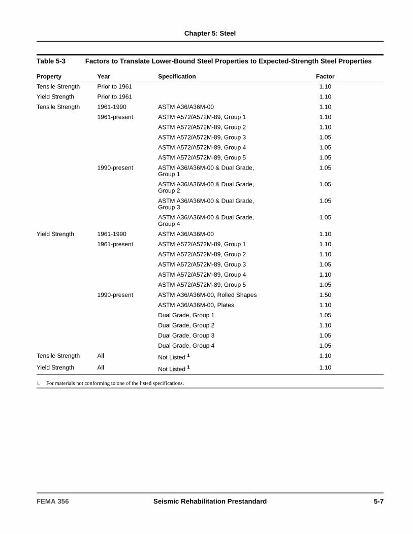
Chapter 5: Steel
Table 5-3 Factors to Translate Lower-Bound Steel Properties to Expected-Strength Steel Properties
Property Year Specification Factor
Tensile Strength Prior to 1961 1.10
Yield Strength Prior to 1961 1.10
Tensile Strength 1961-1990 ASTM A36/A36M-00 1.10
1961-present ASTM A572/A572M-89, Group 1 1.10
ASTM A572/A572M-89, Group 2 1.10
ASTM A572/A572M-89, Group 3 1.05
ASTM A572/A572M-89, Group 4 1.05
ASTM A572/A572M-89, Group 5 1.05
1990-present ASTM A36/A36M-00 & Dual Grade, Group 1
1.05
ASTM A36/A36M-00 & Dual Grade, Group 2
1.05
ASTM A36/A36M-00 & Dual Grade, Group 3
1.05
ASTM A36/A36M-00 & Dual Grade, Group 4
1.05
Yield Strength 1961-1990 ASTM A36/A36M-00 1.10
1961-present ASTM A572/A572M-89, Group 1 1.10
ASTM A572/A572M-89, Group 2 1.10
ASTM A572/A572M-89, Group 3 1.05
ASTM A572/A572M-89, Group 4 1.10
ASTM A572/A572M-89, Group 5 1.05
1990-present ASTM A36/A36M-00, Rolled Shapes 1.50
ASTM A36/A36M-00, Plates 1.10
Dual Grade, Group 1 1.05
Dual Grade, Group 2 1.10
Dual Grade, Group 3 1.05
Dual Grade, Group 4 1.05
Tensile Strength All Not Listed 1 1.10
Yield Strength All Not Listed 1 1.10
1. For materials not conforming to one of the listed specifications.
FEMA 356 Seismic Rehabilitation Prestandard 5-7

Chapter 5: Steel
5.3.3 Condition Assessment
5.3.3.1 General
A condition assessment of the existing building and site shall be performed as specified in this section. A condition assessment shall include the following:
1. Examination of components that will receive earthquake-induced forces or deformations to identify the presence of degradation due to environmental or loading effects.
2. Verification of the presence and configuration of structural elements and components and their connections, and the continuity of load paths between components, elements, and systems.
3. Identification of other conditions including the presence of nonstructural components that influence building performance and impose limitations on rehabilitation.
4. Characterization of soil and foundation conditions as specified in Section 2.2.3.
5. Identification of adjacent buildings as specified in Section 2.2.4.
5.3.3.2 Scope and Procedures
The condition assessment shall include visual inspection of accessible structural elements and components involved in lateral-load resistance to verify information shown on available documents.
If coverings or other obstructions exist, either indirect visual inspection through use of drilled holes and a fiberscope shall be used, or direct visual inspection shall be performed by local removal of covering materials. When required by Section 2.2.6, visual and comprehensive condition assessments shall include the following:
1. If detailed design drawings exist, at least one connection of each connection type shall be exposed. If no deviations from the drawings exist, the sample shall be considered representative. If deviations from the existing drawings exist, then removal of additional coverings from connections of that type shall be done until the extent of deviations is determined.
2. In the absence of construction drawings, at least three primary connections of each connection type shall be exposed. If no deviations within a connection group are observed, the sample shall be considered representative. If deviations within a connection group are observed, then additional connections shall be exposed until the extent of deviations is determined.
C5.3.3.1 General
The physical condition of existing components and elements and their connections must be examined for degradation. Degradation may include environmental effects (e.g., corrosion, fire damage, chemical attack) or past/current loading effects (e.g., overload, damage from past earthquakes, fatigue, fracture). The condition assessment should also examine for configurational problems observed in recent earthquakes, including effects of discontinuous components, improper welding, and poor fit-up.
Component orientation, plumbness, and physical dimensions should be confirmed during an assessment. Connections in steel components, elements, and systems require special consideration and evaluation. The load path for the system must be determined, and each connection in the load path(s) must be evaluated. This includes diaphragm-to-component and component-to-component connections. FEMA 351 provides recommendations for inspection of welded steel moment frames.
The condition assessment also affords an opportunity to review other conditions that may influence steel elements and systems and overall building performance. Of particular importance is the identification of other elements and components that may contribute to or impair the performance of the steel system in question, including infills, neighboring buildings, and equipment attachments. Limitations posed by existing coverings, wall and ceiling space, infills, and other conditions shall also be defined such that prudent rehabilitation measures may be planned.
C5.3.3.2 Scope and Procedures
For steel elements encased in concrete, it may be more cost effective to provide an entirely new lateral-load-resisting system than undertaking a visual inspection by removal of concrete encasement and repair.
5-8 Seismic Rehabilitation Prestandard FEMA 356
Chapter 5: Steel
5.3.3.3 Basis for the Mathematical Building Model
The results of the condition assessment shall be used to create a mathematical building model.
If no damage, alteration, or degradation is observed in the condition assessment, component section properties shall be taken from design drawings. If some sectional material loss or deterioration has occurred, the loss shall be quantified by direct measurement and section properties shall be reduced accordingly using principles of structural mechanics.
5.3.4 Knowledge Factor
A knowledge factor (κ) for computation of steel component capacities and permissible deformations shall be selected in accordance with Section 2.2.6.4 with the following additional requirements specific to steel components.
A knowledge factor of 0.75 shall be used if the components and their connectors are composed of cast or wrought iron.
5.4 General Assumptions and Requirements
5.4.1 Stiffness
Component stiffnesses shall be calculated in accordance with Sections 5.5 through 5.11.
5.4.2 Design Strengths and Acceptance Criteria
5.4.2.1 General
Classification of steel component actions as deformation- or force-controlled, and calculation of design strengths, shall be as specified in Sections 5.5 through 5.10.
5.4.2.2 Deformation-Controlled Actions
Design strengths for deformation-controlled actions, QCE, shall be taken as expected strengths obtained experimentally or calculated using accepted principles of mechanics. Expected strength shall be defined as the mean maximum resistance expected over the range of deformations to which the component is likely to be subjected. When calculations are used to determine mean expected strength, expected material properties (including strain hardening) shall be used. Unless other procedures are specified in this standard, procedures contained in AISC (1993) LRFD Specifications to calculate design strength shall be permitted, except that the strength reduction factor, φ, shall be taken as unity. Deformation capacities for acceptance of deformation-controlled actions shall be as specified in Sections 5.5 through 5.11.
5.4.2.3 Force-Controlled Actions
Design strengths for force-controlled actions, QCL, shall be taken as lower-bound strengths obtained experimentally or calculated using established principles of mechanics. Lower-bound strength shall be defined as mean strength minus one standard deviation. When calculations are used to determine lower-bound strength, lower bound material properties shall be used. Unless other procedures are specified in this standard, procedures contained in AISC (1993) LRFD Specifications to calculate design strength shall be permitted, except that the strength reduction factor, φ, shall be taken as unity. Where alternative definitions of design strength are used, they shall be justified by experimental evidence.
5.4.3 Rehabilitation Measures
Upon determining that steel elements in an existing building are deficient for the selected Rehabilitation Objective, these elements shall be rehabilitated or replaced so they are no longer deficient. If replacement of the element is selected, the new element shall be designed in accordance with an approved building code.
Physical condition of components and connectors may also dictate the use of certain destructive and nondestructive test methods. If steel elements are covered by well-bonded fireproofing materials or encased in durable concrete, it is likely that their condition will be suitable. However, local removal of these materials at connections should be performed as part of the assessment. The scope of this removal effort is dictated by the component and element design. For example, in a braced frame, exposure of several key connections may suffice if the physical condition is acceptable and the configuration matches the design drawings. However, for moment frames, it may be necessary to expose more connection points because of varying designs and the critical nature of the connections. See FEMA 351 for inspection of welded moment frames.
FEMA 356 Seismic Rehabilitation Prestandard 5-9
Chapter 5: Steel
5.5 Steel Moment Frames
5.5.1 General
The behavior of steel moment-resisting frames is generally dependent on the connection configuration and detailing. Table 5-4 identifies the various connection types for which acceptance criteria are provided. Modeling procedures, acceptance criteria, and rehabilitation measures for Fully Restrained (FR) Moment Frames and Partially Restrained (PR) Moment Frames shall be as defined in Sections 5.5.2 and 5.5.3, respectively.
C5.5.1 General
Steel moment frames are those frames that develop their seismic resistance through bending of steel beams and columns, and moment-resisting beam-column connections. A moment-resisting beam-column connection is one that is designed to develop moment resistance at the joint between the beam and the column and also designed to develop the shear resistance at the panel zone of the column. Beams and columns consist of either hot-rolled steel sections or cold-formed steel sections or built-up members from hot-rolled or cold-formed plates and sections. Built-up members are assembled by riveting, bolting, or welding. The components are either bare steel or steel with a nonstructural coating for protection from fire or corrosion or both, or steel with either concrete or masonry encasement.
Following the 1994 Northridge Earthquake, the SAC Joint Venture undertook a major program to address the issue of the seismic performance of moment-resisting steel frame structures. This program produced several documents which provide recommended criteria for the evaluation and upgrade of this building type. However, the design professional should be cautioned that there are some differences in the methodologies and specifics of this standard and the SAC procedures. While both methodologies utilize similar analysis procedures, there are some variations in the factors used to compute the pseudo lateral load in the LSP and NSP. When using the acceptance criteria of this section, the design professional should follow the procedures set forth in Chapter 3 of this standard without modification. The procedures in this standard and the SAC procedures are judged to result in comparable levels of drift demand.
Connections between the members shall be classified as fully restrained (FR) or partially restrained (PR), based on the strength and stiffness of the connection assembly. The connection types and definitions contained in Table 5-4, as well as the acceptance criteria for these connections, has been adopted from the referenced SAC documents, FEMA 350, 351, 355D, and 355F. The number of connections identified is based on research that has shown behavior to be highly dependent on connection detailing. The design professional should refer to those guidelines for more detailed descriptions of these connections as well as a methodology for determining acceptance criteria for other connection types not included in this standard.
FEMA 351 provides an alternate methodology for determining column demands that has not been adopted into this standard.
5-10 Seismic Rehabilitation Prestandard FEMA 356
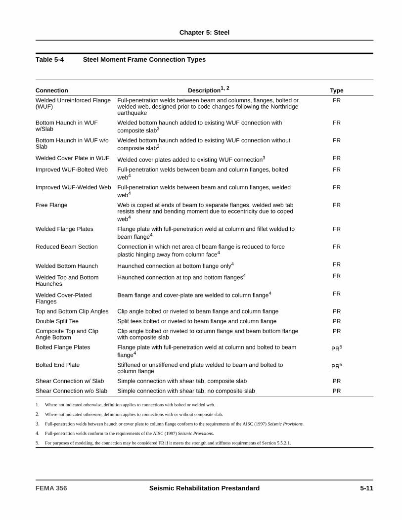
Chapter 5: Steel
Table 5-4 Steel Moment Frame Connection Types
Connection Description1, 2 Type
Welded Unreinforced Flange (WUF)
Full-penetration welds between beam and columns, flanges, bolted or welded web, designed prior to code changes following the Northridge earthquake
FR
Bottom Haunch in WUF w/Slab
Welded bottom haunch added to existing WUF connection with composite slab3
FR
Bottom Haunch in WUF w/o Slab
Welded bottom haunch added to existing WUF connection without composite slab3
FR
Welded Cover Plate in WUF Welded cover plates added to existing WUF connection3 FR
Improved WUF-Bolted Web Full-penetration welds between beam and column flanges, bolted web4
FR
Improved WUF-Welded Web Full-penetration welds between beam and column flanges, welded web4
FR
Free Flange Web is coped at ends of beam to separate flanges, welded web tab resists shear and bending moment due to eccentricity due to coped web4
FR
Welded Flange Plates Flange plate with full-penetration weld at column and fillet welded to beam flange4
FR
Reduced Beam Section Connection in which net area of beam flange is reduced to force plastic hinging away from column face4
FR
Welded Bottom Haunch0 Haunched connection at bottom flange only4 FR
Welded Top and Bottom0 Haunches
Haunched connection at top and bottom flanges4 FR
Welded Cover-Plated0 Flanges
Beam flange and cover-plate are welded to column flange4 FR
Top and Bottom Clip Angles Clip angle bolted or riveted to beam flange and column flange PR
Double Split Tee Split tees bolted or riveted to beam flange and column flange PR
Composite Top and Clip Angle Bottom
Clip angle bolted or riveted to column flange and beam bottom flange with composite slab
PR
Bolted Flange Plates Flange plate with full-penetration weld at column and bolted to beam flange4
PR5
Bolted End Plate Stiffened or unstiffened end plate welded to beam and bolted to column flange
PR5
Shear Connection w/ Slab Simple connection with shear tab, composite slab PR
Shear Connection w/o Slab Simple connection with shear tab, no composite slab PR
1. Where not indicated otherwise, definition applies to connections with bolted or welded web.
2. Where not indicated otherwise, definition applies to connections with or without composite slab.
3. Full-penetration welds between haunch or cover plate to column flange conform to the requirements of the AISC (1997) Seismic Provisions.
4. Full-penetration welds conform to the requirements of the AISC (1997) Seismic Provisions.
5. For purposes of modeling, the connection may be considered FR if it meets the strength and stiffness requirements of Section 5.5.2.1.
FEMA 356 Seismic Rehabilitation Prestandard 5-11

Chapter 5: Steel
5.5.2 Fully Restrained Moment Frames
5.5.2.1 General
Fully restrained (FR) moment frames shall be those moment frames with connections identified as FR in Table 5-4.
Moment frames with connections not included in Table 5-4 shall be defined as FR if the joint deformations (not including panel zone deformation) do not contribute more than 10% to the total lateral deflection of the frame, and the connection is at least as strong as the weaker of the two members being joined. If either of these conditions is not satisfied, the frame shall be characterized as partially restrained.
Fully restrained moment frames encompass both Special Moment Frames and Ordinary Moment Frames, defined in AISC (1997) Seismic Provisions. These terms are not used in this standard, but the requirements for these systems and for general or seismic design of steel components specified in AISC (1993) LRFD Specifications or ASCE 7 shall be followed for new elements designed as part of the seismic rehabilitation, unless superseded by provisions in this standard.
5.5.2.2 Stiffness
5.5.2.2.1 Linear Static and Dynamic Procedures
The stiffness of steel members (columns and beams) and connections (joints and panel zones used with the linear procedures of Chapter 3) shall be based on principles of structural mechanics and as specified in the AISC (1993) LRFD Specifications unless superseded by provisions of this section.
1. Axial Area and Shear Area: [For elements fully encased in concrete, calculation of the stiffness using full composite action shall be permitted if confining reinforcement is provided to allow the concrete to remain in place during an earthquake. Concrete enclosed on at least three sides, or over 75% of its perimeter, by elements of the structural steel member shall be permitted to be considered adequately confined to provide composite action.
2. Moment of Inertia: [For components encased in concrete, the stiffness shall include composite action, but the width of the composite section shall be taken as equal to the width of the flanges of the steel member and shall not include parts of the adjoining floor slab, unless there is an identifiable shear transfer mechanism between the concrete and the steel which is shown to meet the applicable acceptance criteria for the selected performance level.
3. Panel Zone Modeling: [Inclusion of panel zones flexibility shall be permitted in a frame analysis by adding a panel zone element to the mathematical model. Alternatively, adjustment of the beam flexural stiffness to account for panel zone flexibility shall be permitted. Where the expected shear strength of panel zones exceeds the flexural strength of the beams at a beam-column connection, and the stiffness of the panel zone is at least 10 times larger than the flexural stiffness of the beam, direct modeling of the panel zone shall not be required. In such cases, rigid offsets from the center of the column shall be permitted to represent the effective span of the beam. Use of center line analysis shall be permitted for other cases.
4. Joint Modeling: Modeling of connection stiffness for FR moment frames shall not be required except for joints that are intentionally reinforced to force formation of plastic hinges within the beam span, remote from the column face. For such joints, rigid elements shall be used between the column and the beam to represent the effective span of the beam.
5. Connections: Requirements of this section shall apply to connections identified as FR in Table 5-4 and those meeting the requirements of Section 5.5.2.1.
C5.5.2.1 General
FEMA 351 identifies two types of connections—Type 1 (ductile) and Type 2 (brittle). These definitions are not used in this standard since the distinction is reflected in the acceptance criteria for the connections.
The most common beam-to-column connection used in steel FR moment frames since the late 1950s required the beam flange to be welded to the column flange using complete joint penetration groove welds. Many of these connections have fractured during recent earthquakes. The design professional is referred to FEMA 274 and to FEMA 351.
5-12 Seismic Rehabilitation Prestandard FEMA 356
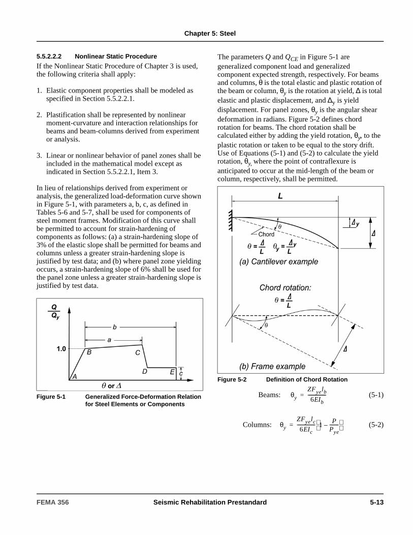
Chapter 5: Steel
5.5.2.2.2 Nonlinear Static Procedure
If the Nonlinear Static Procedure of Chapter 3 is used, the following criteria shall apply:
1. Elastic component properties shall be modeled as specified in Section 5.5.2.2.1.
2. Plastification shall be represented by nonlinear moment-curvature and interaction relationships for beams and beam-columns derived from experiment or analysis.
3. Linear or nonlinear behavior of panel zones shall be included in the mathematical model except as indicated in Section 5.5.2.2.1, Item 3.
In lieu of relationships derived from experiment or analysis, the generalized load-deformation curve shown in Figure 5-1, with parameters a, b, c, as defined in Tables 5-6 and 5-7, shall be used for components of steel moment frames. Modification of this curve shall be permitted to account for strain-hardening of components as follows: (a) a strain-hardening slope of 3% of the elastic slope shall be permitted for beams and columns unless a greater strain-hardening slope is justified by test data; and (b) where panel zone yielding occurs, a strain-hardening slope of 6% shall be used for the panel zone unless a greater strain-hardening slope is justified by test data.
The parameters Q and QCE in Figure 5-1 are generalized component load and generalized component expected strength, respectively. For beams and columns, θ is the total elastic and plastic rotation of the beam or column, θy is the rotation at yield, ∆ is total elastic and plastic displacement, and ∆y is yield displacement. For panel zones, θy is the angular shear deformation in radians. Figure 5-2 defines chord rotation for beams. The chord rotation shall be calculated either by adding the yield rotation, θy, to the plastic rotation or taken to be equal to the story drift. Use of Equations (5-1) and (5-2) to calculate the yield rotation, θy, where the point of contraflexure is anticipated to occur at the mid-length of the beam or column, respectively, shall be permitted.
Beams: (5-1)
Columns: (5-2)
Figure 5-1 Generalized Force-Deformation Relation for Steel Elements or Components
Figure 5-2 Definition of Chord Rotation
θy
ZFyelb
6EIb----------------=
θy
ZFyelc
6EIc---------------- 1
PPye--------–
=
FEMA 356 Seismic Rehabilitation Prestandard 5-13

Chapter 5: Steel
Q and QCE are the generalized component load and generalized component expected strength, respectively. For flexural actions of beams and columns, QCE refers to the plastic moment capacity, which shall be calculated using Equations (5-3) and (5-4):
Beams:
(5-3)
Columns:
(5-4)
For panel zones, QCE refers to the plastic shear capacity of the panel zone, which shall be calculated using Equation (5-5):
Panel Zones:
(5-5)
where:
5.5.2.2.3 Nonlinear Dynamic Procedure
The complete hysteretic behavior of each component shall be determined experimentally.
5.5.2.3 Strength
5.5.2.3.1 General
Component strengths shall be computed in accordance with the general requirements of Section 5.4.2 and the specific requirements of this section.
5.5.2.3.2 Linear Static and Dynamic Procedures
1. Beams: The strength of elements of structural steel under flexural actions with negligible axial load present shall be calculated in accordance with this section. These actions shall be considered deformation-controlled.
The expected flexural strength, QCE, of beam components shall be determined using equations for design strength, Mp, given in AISC (1997) Seismic Provisions, except that φ shall be taken as 1.0 and Fye shall be substituted for Fy. The component expected strength, QCE, of beams and other flexural deformation-controlled members shall be the lowest value obtained for the limit states of yielding, lateral-torsional buckling, local flange buckling, or shear yielding of the web.
dc = Column depth
E = Modulus of elasticity
Fye = Expected yield strength of the material
I = Moment of inertia
lb = Beam length
lc = Column length
MCE = Expected flexural strength
P = Axial force in the member at the target displacement for nonlinear static analyses, or at the instant of computation for nonlinear dynamic analyses. For linear analyses, P shall be taken as QUF, calculated in accordance with Section 3.4.2.1.2
Pye = Expected axial yield force of the member = AgFye
Q = Generalized component load
QCE = Generalized component expected strength
QCE MCE ZFye= =
QCE MCE 1.18ZFye 1P
Pye--------–
ZFye≤= =
QCE VCE 0.55Fyedctp= =
tp = Total thickness of panel zone including doubler plates
θ = Chord rotation
θy = Yield rotation
VCE = Expected shear strength
Z = Plastic section modulus
C5.5.2.2.2 Nonlinear Static Procedure
Strain hardening should be considered for all components. The design professional is directed to FEMA 355D for information concerning nonlinear behavior of various tested connection configurations.
C5.5.2.2.3 Nonlinear Dynamic Procedure
The design professional is directed to FEMA 355D for information concerning nonlinear behavior of various tested connection configurations.
5-14 Seismic Rehabilitation Prestandard FEMA 356
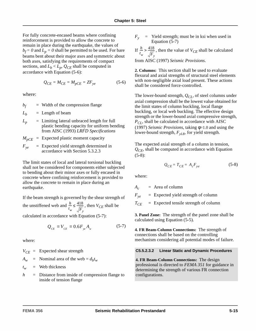
Chapter 5: Steel
For fully concrete-encased beams where confining reinforcement is provided to allow the concrete to remain in place during the earthquake, the values of bf = 0 and Lp = 0 shall be permitted to be used. For bare beams bent about their major axes and symmetric about both axes, satisfying the requirements of compact sections, and Lb < Lp, QCE shall be computed in accordance with Equation (5-6):
QCE = MCE = MpCE = ZFye (5-6)
where:
The limit states of local and lateral torsional buckling shall not be considered for components either subjected to bending about their minor axes or fully encased in concrete where confining reinforcement is provided to allow the concrete to remain in place during an earthquake.
If the beam strength is governed by the shear strength of
the unstiffened web and , then VCE shall be
calculated in accordance with Equation (5-7):
(5-7)
where:
If , then the value of VCE shall be calculated
from AISC (1997) Seismic Provisions.
2. Columns: This section shall be used to evaluate flexural and axial strengths of structural steel elements with non-negligible axial load present. These actions shall be considered force-controlled.
The lower-bound strength, QCL, of steel columns under axial compression shall be the lowest value obtained for the limit states of column buckling, local flange buckling, or local web buckling. The effective design strength or the lower-bound axial compressive strength, PCL, shall be calculated in accordance with AISC (1997) Seismic Provisions, taking φ=1.0 and using the lower-bound strength, FyLB, for yield strength.
The expected axial strength of a column in tension, QCE, shall be computed in accordance with Equation (5-8):
(5-8)
where:
3. Panel Zone: The strength of the panel zone shall be calculated using Equation (5-5).
4. FR Beam-Column Connections: The strength of connections shall be based on the controlling mechanism considering all potential modes of failure.
bf = Width of the compression flange
Lb = Length of beam
Lp = Limiting lateral unbraced length for full plastic bending capacity for uniform bending from AISC (1993) LRFD Specifications
MpCE = Expected plastic moment capacity
Fye = Expected yield strength determined in accordance with Section 5.3.2.3
VCE = Expected shear strength
Aw = Nominal area of the web = dbtw
tw = Web thickness
h = Distance from inside of compression flange to inside of tension flange
htw----- 418
Fy
----------≤
wyeCECEAFVQ 6.0==
Fy = Yield strength; must be in ksi when used in Equation (5-7)
Ac = Area of column
Fye = Expected yield strength of column
TCE = Expected tensile strength of column
C5.5.2.3.2 Linear Static and Dynamic Procedures
4. FR Beam-Column Connections: The design professional is directed to FEMA 351 for guidance in determining the strength of various FR connection configurations.
htw----- 418
Fy
---------->
QCE TCE AcFye==
FEMA 356 Seismic Rehabilitation Prestandard 5-15
Chapter 5: Steel
5. Column Base Plate to Concrete Pile Caps or Footings: The strength of connections between columns and concrete pile caps or footings shall be the lowest value obtained for the limit states of the strength of the columns, the strength of the base plates, and the strength of the anchor bolts. The strength of the base plate shall be the lowest value based on the following limit states: expected strength of the welds or bolts, expected bearing stress of the concrete, and expected yield strength, Fye, of the base plate.
The strength of the anchor bolt connection between the base plate and the concrete shall be the lowest value based on the following limit states: shear or tension yield strength of the anchor bolts, loss of bond between the anchor bolts and the concrete, or failure of the concrete. Anchor bolt strengths for each failure type or limit state shall be calculated in accordance with IBC, Section 1913, using φ=1.0, or other approved procedure.
5.5.2.3.3 Nonlinear Static Procedure
The complete load-deformation relationship of each component as depicted in Figure 5-1 shall be determined in accordance with Section 5.5.2.2.2. The values for expected strength, QCE, shall be the same as those used for linear procedures as specified in Section 5.5.2.3.2.
5.5.2.3.4 Nonlinear Dynamic Procedures
The complete hysteretic behavior of each component shall be determined experimentally.
5.5.2.4 Acceptance Criteria
5.5.2.4.1 General
Component acceptance criteria shall be computed in accordance with the general requirements of Section 5.4.2 and the specific requirements of this section.
5.5.2.4.2 Linear Static and Dynamic Procedures
1. Beams: The acceptance criteria of this section shall apply to flexural actions of elements of structural steel with negligible axial load. Beam flexure and shear shall be considered deformation-controlled.
For built-up shapes, the adequacy of lacing plates shall be evaluated using the provisions for tension braces in Section 5.6.2.4.
Values for the m-factor used in Equation (3-20) shall be as specified in Table 5-5. For fully concrete-encased beams where confining reinforcement is provided to allow the concrete to remain in place during an earthquake, the values of bf = 0 and Lp = 0 shall be used for the purpose of determining m. If QCE < MpCE due to lateral torsional buckling, then m in Equation (3-20) shall be replaced by me, calculated in accordance with Equation (5-9):
(5-9)
where:
C5.5.2.3.4 Nonlinear Dynamic Procedures
The design professional is directed to FEMA 355D for information concerning nonlinear behavior of various tested connection configurations.
C5.5.2.4.1 General
The strength and behavior of steel moment-resisting frames is typically governed by the connections. The design professional is urged to determine the controlling limit state of the system when selecting the corresponding acceptance criterion.
Lb = Distance between points braced against lateral displacement of the compression flange, or between points braced to prevent twist of the cross-section, AISC (1993) LRFD Specifications
Lp = Limiting unbraced length between points of lateral restraint for the full plastic moment capacity to be effective, AISC (1993) LRFD Specifications
Lr = Limiting unbraced length between points of lateral support beyond which elastic lateral torsional buckling of the beam is the failure mode, AISC (1993) LRFD Specifications
m = Value of m given in Table 5-5
me = Effective m computed in accordance with Equation (5-9)
Cb = Coefficient to account for effect of nonuniform moment, AISC (1993) LRFD Specifications
me Cb m m 1–( )Lb Lp–
Lr Lp–-----------------–=
5-16 Seismic Rehabilitation Prestandard FEMA 356
Chapter 5: Steel
For built-up shapes, where the strength is governed by the strength of the lacing plates that carry component shear, the m-factor shall be taken as 0.5 times the applicable value in Table 5-5, unless larger values are justified by tests or analysis; however, m need not be taken less than 1.0. For built-up laced beams and columns fully encased in concrete, local buckling of the lacing need not be considered where confining reinforcement is provided to allow the encasement to remain in place during a design earthquake.
2. Columns: For steel columns under combined axial compression and bending stress, where the axial column load is less than 50% of the lower-bound axial column strength, PCL, the column shall be considered deformation-controlled for flexural behavior and force-controlled for compressive behavior and the combined strength shall be evaluated by Equation (5-10) or (5-11).
For
(5-10)
For
(5-11)
where:
Steel columns with axial compressive forces exceeding 50% of the lower-bound axial compressive strength, PCL, shall be considered force-controlled for both axial loads and flexure and shall be evaluated using Equation (5-12):
(5-12)
where:
Flexural strength shall be calculated in accordance with AISC (1997) Seismic Provisions taking φ=1.0 and using the lower-bound value for yield strength.
For columns under combined compression and bending, lateral bracing to prevent torsional buckling shall be provided as required by the AISC (1993) LRFD Specifications.
Steel columns under axial tension shall be considered deformation-controlled and shall be evaluated using Equation (3-20).
Steel columns under combined axial tension and bend-ing stress shall be considered deformation-controlled and shall be evaluated using Equation (5-13):
(5-13)
PUF = Axial force in the member computed in accordance with Section 3.4.2.1.2
PCL = Lower-bound compression strength of the column
Mx = Bending moment in the member for the x-axis computed in accordance with Section 3.4.2.1.1
My = Bending moment in the member for the y-axis computed in accordance with Section 3.4.2.1.1
MCEx = Expected bending strength of the column for the x-axis
MCEy = Expected bending strength of the column for the y-axis
0.2PUF
PCL---------- 0.5≤ ≤
PUF
PCL---------- 8
9---
Mx
mxMCEx---------------------
My
myMCEy--------------------++ 1.0≤
PUF
PCL---------- 0.2<
PUF
2PCL
------------Mx
mxMCEx--------------------
My
myMCEy--------------------++ 1.0≤
mx = Value of m for the column bending about the x-axis in accordance with Table 5-5
my = Value of m for the column bending about the y-axis in accordance with Table 5-5
PUF = Axial load in the member, calculated in accordance with Section 3.4.2.1.2
MUFx = Bending moment in the member about the x-axis, calculated in accordance with Section 3.4.2.1.2
MUFy = Bending moment in the member about the y-axis, calculated in accordance with Section 3.4.2.1.2
MCLx = Lower-bound flexural strength of the member about the x-axis
MCLy = Lower-bound flexural strength of the member about the y-axis
PUF
PCL
----------MuFx
MCLx--------------
MuFy
MCLy--------------++ 1≤
TmtTCE
----------------Mx
mxMCEx--------------------
My
myMCEy--------------------++ 1.0≤
FEMA 356 Seismic Rehabilitation Prestandard 5-17
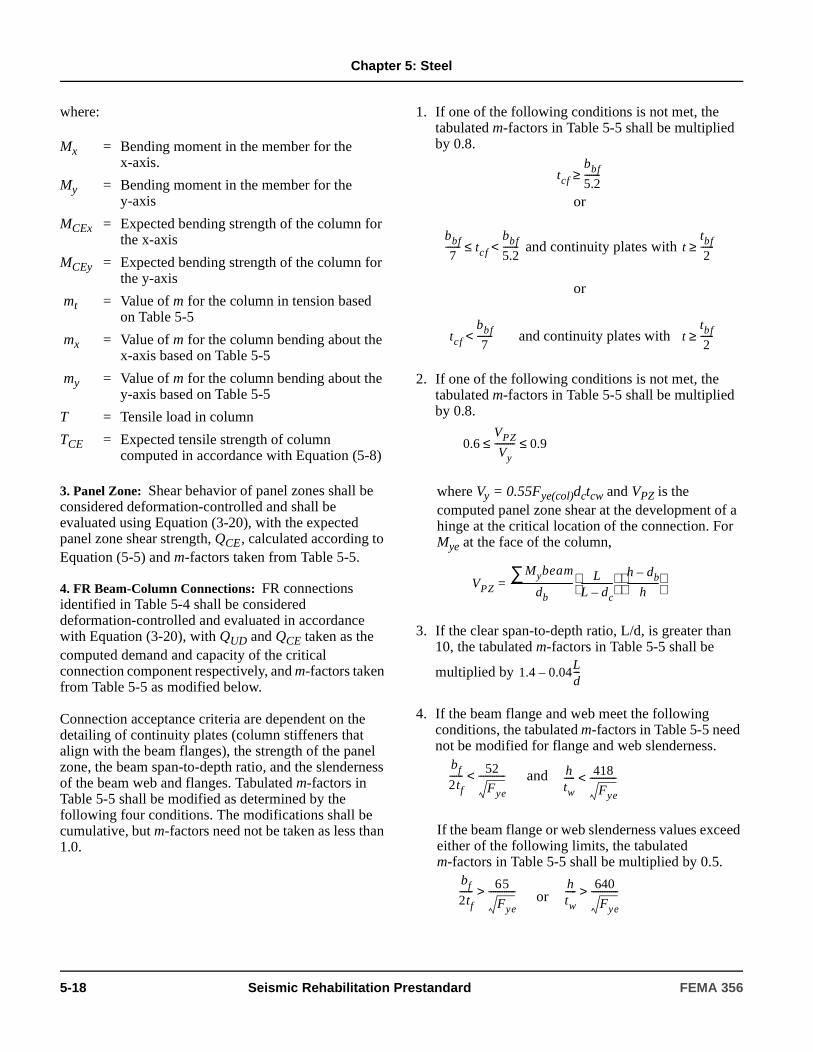
Chapter 5: Steel
where:
3. Panel Zone: Shear behavior of panel zones shall be considered deformation-controlled and shall be evaluated using Equation (3-20), with the expected panel zone shear strength, QCE, calculated according to Equation (5-5) and m-factors taken from Table 5-5.
4. FR Beam-Column Connections: FR connections identified in Table 5-4 shall be considered deformation-controlled and evaluated in accordance with Equation (3-20), with QUD and QCE taken as the computed demand and capacity of the critical connection component respectively, and m-factors taken from Table 5-5 as modified below.
Connection acceptance criteria are dependent on the detailing of continuity plates (column stiffeners that align with the beam flanges), the strength of the panel zone, the beam span-to-depth ratio, and the slenderness of the beam web and flanges. Tabulated m-factors in Table 5-5 shall be modified as determined by the following four conditions. The modifications shall be cumulative, but m-factors need not be taken as less than 1.0.
1. If one of the following conditions is not met, the tabulated m-factors in Table 5-5 shall be multiplied by 0.8.
or
and continuity plates with
or
and continuity plates with
2. If one of the following conditions is not met, the tabulated m-factors in Table 5-5 shall be multiplied by 0.8.
where Vy = 0.55Fye(col)dctcw and VPZ is the computed panel zone shear at the development of a hinge at the critical location of the connection. For Mye at the face of the column,
3. If the clear span-to-depth ratio, L/d, is greater than 10, the tabulated m-factors in Table 5-5 shall be
multiplied by
4. If the beam flange and web meet the following conditions, the tabulated m-factors in Table 5-5 need not be modified for flange and web slenderness.
and
If the beam flange or web slenderness values exceed either of the following limits, the tabulated m-factors in Table 5-5 shall be multiplied by 0.5.
or
Mx = Bending moment in the member for the x-axis.
My = Bending moment in the member for the y-axis
MCEx = Expected bending strength of the column for the x-axis
MCEy = Expected bending strength of the column for the y-axis
mt = Value of m for the column in tension based on Table 5-5
mx = Value of m for the column bending about the x-axis based on Table 5-5
my = Value of m for the column bending about the y-axis based on Table 5-5
T = Tensile load in column
TCE = Expected tensile strength of column computed in accordance with Equation (5-8)
tcf
bbf
5.2-------≥
bbf
7------- tcf
bbf
5.2-------<≤ t
tbf
2------≥
tcf
bbf
7-------< t
tbf
2------≥
0.6VPZ
Vy--------- 0.9≤ ≤
VPZ
Mybeam∑db
----------------------------=L
L dc–--------------
h db–
h--------------
1.4 0.04Ld---–
bf
2tf------ 52
Fye
------------< htw----- 418
Fye
------------<
bf
2tf------ 65
Fye
------------> htw----- 640
Fye
------------>
5-18 Seismic Rehabilitation Prestandard FEMA 356
Chapter 5: Steel
Straight line interpolation, based on the case that results in the lower modifier, shall be used for intermediate values of beam flange or web slenderness.
Type FR connections designed to promote yielding of the beam remote from the column face shall be considered force-controlled and shall be designed using Equation (5-14):
(5-14)
where:
5. Column Base Plate to Concrete Pile Caps or Footings: For column base plate yielding, bolt yielding, and weld failure, the use of m-factors from Table 5-5, based on the respective limit states for partially restrained end plates, shall be permitted. Column-base connection limit states controlled by anchor bolt failure modes governed by the concrete shall be considered force-controlled.
5.5.2.4.3 Nonlinear Static and Dynamic Procedures
Calculated component actions shall satisfy the requirements of Section 3.4.3. Maximum permissible inelastic deformations shall be taken from Tables 5-6 and 5-7.
1. Beams: Flexural actions of beams shall be considered deformation-controlled. Permissible plastic rotation deformation shall be as indicated in Tables 5-6 and 5-7, where θy shall be calculated in accordance with Section 5.5.2.2.2.
2. Columns: Axial compressive loading of columns shall be considered force-controlled, with the lower-bound axial compression capacity, PCL, computed in accordance with Section 5.5.2.4.2.
Flexural loading of columns, with axial loads at a target displacement less than 50% of PCL, computed in accordance with Section 5.5.2.4.2, shall be considered deformation-controlled and maximum permissible plastic rotation demands on columns, in radians, shall be as indicated in Tables 5-6 and 5-7, dependent on the axial load present and the compactness of the section.
Flexural loading of columns, with axial loads at the target displacement greater than or equal to 50% of PCL, computed in accordance with Section 5.5.2.4.2, shall be considered force-controlled and shall conform to Equation (5-11).
QCLc = The lower-bound strength of the connection
QCEb = Expected bending strength of the beam
C5.5.2.4.2 Linear Static and Dynamic Procedures
4. FR Beam-Column Connections. The continuity plate modifier is based on recommendations FEMA 355F for continuity plate detailing in relationship to column flange thickness.
The panel zone modifier is based on research in FEMA 355F indicating that connection performance is less ductile when the strength of the panel zone is either too great or too small compared to the flexural strength of the beam. The panel zone range between 60 percent to 90 percent of the beam strength is considered to provide balanced yielding between the beam and panel zone, which results in more desirable performance.
QCLc QCEb≥
The clear span-to-depth ratio modifier for linear acceptance criteria reflects the decreased apparent ductility that arises due to increased elastic rotations for longer beams. The decreased plastic rotation capacity of beams with very small L/d ratios is not reflected directly. However, the modifier for linear criteria was developed so that it would be appropriate for the predominant case of L/d ratios greater than about 5.
The beam flange and web slenderness modifier is based on the same modifications to beam acceptance criteria contained in Table 5-5. While not an aspect of the connection itself, beam flange and web slenderness affect the behavior of the connection assembly.
Type FR connections designed to promote yielding of the beam in the span, remote from the column face, are discussed in FEMA 350.
FEMA 356 Seismic Rehabilitation Prestandard 5-19
Chapter 5: Steel
3. FR Connection Panel Zones: Plastic rotation demands on panel zones, shall be evaluated using the acceptance criteria provided in Tables 5-6 and 5-7.
4. FR Beam-Column Connections: FR connections identified in Table 5-4 shall be considered deformation-controlled and the plastic rotation predicted by analysis shall be compared with the acceptance criteria in Tables 5-6 and 5-7 as modified below. Connection acceptance criteria are dependent on the detailing of continuity plates, the strength of the panel zone, the beam span-to-depth ratio, and the slenderness of the beam web and flanges as determined by the following four conditions. The modifications shall be cumulative.
1. If one of the following conditions is not met, the tabulated plastic rotation in Tables 5-6 and 5-7 shall be multiplied by 0.8.
or
and continuity plates with
or
and continuity plates with
2. If the following condition is not met, the tabulated plastic rotations in Tables 5-6 and 5-7 shall be multiplied by 0.8.
where Vy = 0.55Fye(col)dctcw and VPZ is the computed panel zone shear at the development of a hinge at the critical location of the connection. For Mye at the face of the column,
3. If the clear span-to-depth ratio, L/d, is less than 8, the tabulated plastic rotations in Tables 5-6 and 5-7
shall be multiplied by
4. If the beam flange and web meet the following conditions, the tabulated plastic rotations in Tables 5-6 and 5-7 need not be modified for flange and web slenderness.
and
If the beam flange or web slenderness values exceed either of the following limits, the tabulated plastic rotations Tables 5-6 and 5-7 shall be multiplied by 0.5.
or
Straight line interpolation, based on the case that results in the lower modifier, shall be used for intermediate values of beam flange or web slenderness.
Type FR connections designed to promote yielding of the beam in the span remote from the column face, shall be considered force-controlled and shall be evaluated to assure that the lower-bound strength of the connection exceeds the expected flexural strength of the beam at the connection.
tcf
bbf
5.2-------≥
bbf
7------- tcf
bbf
5.2-------<≤ t
tbf
2------≥
tcf
bbf
7-------< t tbf≥
0.6VPZ
Vy--------- 0.9≤ ≤
VPZ
Mybeam∑db
----------------------------=L
L dc–--------------
h db–
h--------------
C5.5.2.4.3 Nonlinear Static and Dynamic Procedures
4. FR Beam-Column Connections: The continuity plate modifier is based on recommendations in FEMA 355F for continuity plate detailing in relationship to column flange thickness.
The panel zone modifier is based on research in FEMA 355F indicating that connection performance is less ductile when the strength of the panel zone is either too great or too small compared to the flexural strength of the beam. The panel zone range between 60 percent to 90 percent of the beam strength is considered to provide balanced yielding between the beam and panel zone, which results in more desirable performance.
0.5( ) 8 L d⁄–3
-------------------
bf
2tf------ 52
Fye
------------< htw----- 418
Fye
------------<
bf
2tf------ 65
Fye
------------> htw----- 640
Fye
------------>
5-20 Seismic Rehabilitation Prestandard FEMA 356

Chapter 5: Steel
5.5.2.5 Rehabilitation Measures
FR moment frame components that do not meet the acceptance criteria for the selected Rehabilitation Objective shall be rehabilitated. Rehabilitation measures shall meet the requirements of Section 5.4.3 and other provisions of this standard.
The clear span-to-depth ratio modifier for nonlinear modeling and acceptance criteria reflects decreased plastic rotation capacity for beams with hinging occurring over a shorter length. This modifier is based on the plastic rotation capacities corresponding to the FEMA 350 L/d limits of 5 and 8.
The beam flange and web slenderness modifier is based on the same modifications to beam acceptance criteria contained in Tables 5-6 and 5-7. While not an aspect of the connection itself, beam flange and web slenderness affects the behavior of the connection assembly.
Type FR connections designed to promote yielding of the beam in the span, remote from the column face, are discussed in FEMA 350.
C5.5.2.5 Rehabilitation Measures
The following measures, which are presented in greater detail in FEMA 351, may be effective in rehabilitating FR moment frames:
1. Add steel braces to one or more bays of each story to form concentric or eccentric braced frames to increase the stiffness of the frames. The attributes and design criteria for braced frames shall be as specified in Section 5.6. The location of added braces should be selected so as to not increase horizontal torsion in the system.
2. Add ductile concrete or masonry shear walls or infill walls to one or more bays of each story to increase the stiffness and strength of the structure. The attributes and design requirements of concrete and masonry shear walls shall be as specified in Sections 6.8 and 7.4, respectively. The attributes and design requirements of concrete and masonry infills shall be as specified in Sections 6.7 and 7.5, respectively. The location of added walls should be selected so as not to increase horizontal torsion in the system.
3. Attach new steel frames to the exterior of the building. The rehabilitated structure should be checked for the effects of the change in the distribution of stiffness, the seismic load path, and the connections between the new and existing frames. The rehabilitation scheme of attaching new steel frames to the exterior of the building has been used in the past and has been shown to be very effective under certain conditions. This rehabilitation approach may be structurally efficient, but it changes the architectural appearance of the building. The advantage is that the rehabilitation may take place without disrupting the use of the building.
4. Reinforce moment-resisting connections to force plastic hinge locations in the beam material away from the joint region to reduce the stresses in the welded connection, thereby reducing the possibility of brittle fractures. This scheme should not be used if the full-pen connection of the existing structure did not use weld material of sufficient toughness to avoid fracture at stresses lower than yield or when strain hardening at the new hinge location produces larger stresses than existing at the weld. The rehabilitation measures to reinforce selected moment-resisting connections shall consist of providing horizontal cover plates, vertical stiffeners, or haunches. Removal of beam material to force plastic hinge in the beam and away from the joint region shall also be permitted subject to the above restrictions. Guidance on the design of these modifications of FR moment connections is discussed in FEMA 351.
5. Add energy dissipation devices as specified in Chapter 9.
6. Increase the strength and stiffness of existing frames by welding steel plates or shapes to selected members.
FEMA 356 Seismic Rehabilitation Prestandard 5-21

Chapter 5: Steel
5.5.3 Partially Restrained Moment Frames
5.5.3.1 General
Partially restrained (PR) moment frames shall be defined as those moment frames with connections identified as PR in Table 5-4. Moment frames with connections not included in Table 5-4 shall be defined as PR if the deformations of the beam-to-column joints contribute greater than 10% to the total lateral deflection of the frame or where the strength of the connections is less than the strength of the weaker of the two members being joined. For a PR connection with two or more failure modes, the weakest failure mechanism shall be considered to govern the behavior of the joint. Design provisions for PR frames specified in AISC (1997) Seismic Provisions or ASCE 7 shall apply unless superseded by the provisions in this standard. Equations for calculating nominal design strength shall be used for determining the expected strength, except φ = 1, and either the expected strength or lower-bound strength shall be used in place of Fy, as further indicated in this standard.
5.5.3.2 Stiffness
5.5.3.2.1 Linear Static and Dynamic Procedures
1. Beams, columns, and panel zones: Axial area, shear area, moment of inertia, and panel zone stiffness shall be determined as specified in Section 5.5.2.2 for FR frames.
2. Connections: The rotational stiffness Kθ of each PR connection for use in PR frame analysis shall be determined by the procedure of this section, by experiment, or by an approved rational analysis. The deformation of the connection shall be included when calculating frame displacements.
The rotational spring stiffness, Kθ, shall be calculated in accordance with Equation (5-15):
(5-15)
where:
MCE =Expected moment strength of connection for the following PR connections:
1. PR connections encased in concrete, where the nominal resistance, MCE, determined for the connection shall include the composite action provided by the concrete encasement.
2. PR connections encased in masonry, where composite action shall not be included in the determination of connection resistance, MCE.
3. Bare steel PR connections.
For PR connections not listed above, the rotational spring stiffness shall be calculated in accordance with Equation (5-16):
(5-16)
As a simplified alternative, modeling the frame as for FR joints but with the beam stiffness, EIb, adjusted to account for the flexibility of the joints in accordance with Equation (5-17) shall be permitted:
(5-17)
C5.5.3.1 General
Table 5-4 includes simple shear or pinned connections classified as PR connections. Although the gravity load carrying beams and columns are typically neglected in the lateral analysis of steel moment frame structures, SAC research contained in FEMA 355D indicates that these connections are capable of contributing non-negligible stiffness through very large drift demands. Including gravity load carrying elements (subject to the modeling procedures and acceptance criteria in this section) in the mathematical model could be used by the design engineer to reduce the demands on the moment frame elements.
KθMCE
0.005-------------=
KθMCE
0.003-------------=
EIb adjusted1
6h
Lb2Kθ
------------- 1EIb--------+
----------------------------=
5-22 Seismic Rehabilitation Prestandard FEMA 356
Chapter 5: Steel
where:
When Equation (5-17) is used, the adjusted beam stiffness shall be used in standard rigid-connection frame analysis and the rotation of the connection shall be taken as the rotation of the beam at the joint.
5.5.3.2.2 Nonlinear Static Procedure
If the Nonlinear Static Procedure of Chapter 3 is used, the following criteria shall apply:
1. The elastic component properties shall be modeled as specified in Section 5.5.3.2.1.
2. The nonlinear moment-curvature or load-deformation behavior for beams, beam-columns, and panel zones shall be modeled as specified in Section 5.5.2.2 for FR frames.
3. In lieu of relationships derived from experiment or analysis, the generalized load-deformation curve shown in Figure 5-1 with its parameters a, b, c as defined in Tables 5-6 and 5-7, shall be used to represent moment-rotation behavior for PR connections in accordance with Section 5.5.2.2.2. The value for θy shall be 0.005 for connections, for which Equation (5-15) in Section 5.5.3.2.1 applies, or 0.003 for all other connections.
5.5.3.2.3 Nonlinear Dynamic Procedure
The complete hysteretic behavior of each component shall be modeled as verified by experiment.
5.5.3.3 Strength
5.5.3.3.1 General
Component strengths shall be computed in accordance with the general requirements of Section 5.4.2 and the specific requirements of this section.
5.5.3.3.2 Linear Static and Dynamic Procedures
The strength of steel beams and columns in PR Frames being analyzed using linear procedures shall be computed in accordance with Section 5.5.2.3.2 for FR Frames.
The expected strength, QCE, for PR connections shall be based on procedures specified in AISC (1993) LRFD Specifications, based on experiment, or based on the procedures listed in the subsequent sections.
1. Top and Bottom Clip Angle Connection: The moment strength, MCE, of the riveted or bolted clip angle connection, as shown in Figure 5-3, shall be the smallest value of MCE computed for the following four limits states:
1.1 Limit State 1: If the shear connectors between the beam flange and the flange angle control the capacity of the connection, QCE shall be computed in accordance with Equation (5-18):
(5-18)
Kθ = Equivalent rotational spring stiffness of connection per Equation (5-15) or (5-16)
MCE = Expected moment strength
Ib = Moment of inertia of the beam
E = Modulus of elasticity
h = Average story height of the columns
Lb = Centerline span of the beam
C5.5.3.2.1 Linear Static and Dynamic Procedures
The design professional is directed to FEMA 274 for information concerning stiffness properties and modeling guidelines for PR connections.
C5.5.3.2.2 Nonlinear Static Procedure
The design professional is directed to FEMA 355D for information concerning nonlinear behavior of various tested connection configurations.
C5.5.3.2.3 Nonlinear Dynamic Procedure
The design professional is directed to FEMA 355D for information concerning nonlinear behavior of various tested connection configurations.
QCE MCE db FveAbNb( )==
FEMA 356 Seismic Rehabilitation Prestandard 5-23
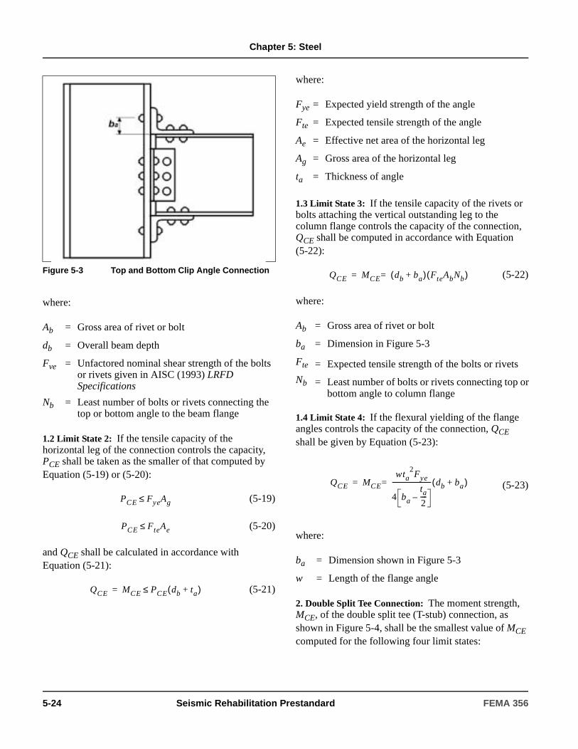
Chapter 5: Steel
where:
1.2 Limit State 2: If the tensile capacity of the horizontal leg of the connection controls the capacity, PCE shall be taken as the smaller of that computed by Equation (5-19) or (5-20):
(5-19)
(5-20)
and QCE shall be calculated in accordance with Equation (5-21):
(5-21)
where:
1.3 Limit State 3: If the tensile capacity of the rivets or bolts attaching the vertical outstanding leg to the column flange controls the capacity of the connection, QCE shall be computed in accordance with Equation (5-22):
(5-22)
where:
1.4 Limit State 4: If the flexural yielding of the flange angles controls the capacity of the connection, QCE shall be given by Equation (5-23):
(5-23)
where:
2. Double Split Tee Connection: The moment strength, MCE, of the double split tee (T-stub) connection, as shown in Figure 5-4, shall be the smallest value of MCE computed for the following four limit states:
Figure 5-3 Top and Bottom Clip Angle Connection
Ab = Gross area of rivet or bolt
db = Overall beam depth
Fve = Unfactored nominal shear strength of the bolts or rivets given in AISC (1993) LRFD Specifications
Nb = Least number of bolts or rivets connecting the top or bottom angle to the beam flange
PCE FyeAg≤
PCE FteAe≤
QCE MCE PCE db ta+( )≤=
Fye = Expected yield strength of the angle
Fte = Expected tensile strength of the angle
Ae = Effective net area of the horizontal leg
Ag = Gross area of the horizontal leg
ta = Thickness of angle
Ab = Gross area of rivet or bolt
ba = Dimension in Figure 5-3
Fte = Expected tensile strength of the bolts or rivets
Nb = Least number of bolts or rivets connecting top orbottom angle to column flange
ba = Dimension shown in Figure 5-3
w = Length of the flange angle
QCE MCE db ba+( ) FteAbNb( )==
QCE MCE
wta2Fye
4 ba
ta
2----–
------------------------- db ba+( )==
5-24 Seismic Rehabilitation Prestandard FEMA 356

Chapter 5: Steel
2.1 Limit State 1: If the shear connectors between the beam flange and the web of the split tee control the capacity of the connection, QCE shall be calculated using Equation (5-18).
2.2 Limit State 2: If the tension capacity of the bolts orrivets connecting the flange of the split tee to the col-umn flange control the capacity of the connection, QCEshall be calculated using Equation (5-24):
(5-24)
where:
2.3 Limit State 3: If tension in the stem of the split tee controls the capacity of the connection, Equations (5-21) and (5-22) shall be used to determine QCE, with Ag and Ae being the gross and net areas of the split tee stem and replacing ta with ts.
2.4 Limit State 4: If flexural yielding of the flanges of the split tee controls the capacity of the connection, QCE shall be determined in accordance with Equation (5-25):
(5-25)
where:
3. Bolted Flange Plate Connections: [For bolted flange plate connections, as shown in Figure 5-5, the flange plate shall be welded to the column and welded or bolted to the beam flange. This connection shall be considered fully restrained if its strength equals or exceeds the strength of the connected beam. The expected strength of the connection shall be calculated in accordance with Equation (5-26):
(5-26)
Figure 5-4 Double Split Tee Connection
db = Overall beam depth
bt = Distance between one row of fasteners in the split tee flange and the centerline of the stem as shown in Figure 5-4
ts = Thickness of the split tee stem
Fte = Expected tensile strength of the bolts or rivets
QCE MCE db 2bt ts+ +( ) FteAbNb( )==
Ab = Gross area of rivet or bolt
Nb = Number of fasteners in tension connecting the flanges of one split tee to the column flange
k1 = Distance from the center of the split tee stem to the edge of the split tee flange fillet
bt = Distance between one row of fasteners in the split tee flange and the centerline of the stem as shown in Figure 5-4
w = Length of split tee
tf = Thickness of split tee flange
QCE MCE
db ts+( )wtf2Fye
2 bt k1–( )----------------------------------------==
QCE MCE PCE db tp+( )==
FEMA 356 Seismic Rehabilitation Prestandard 5-25
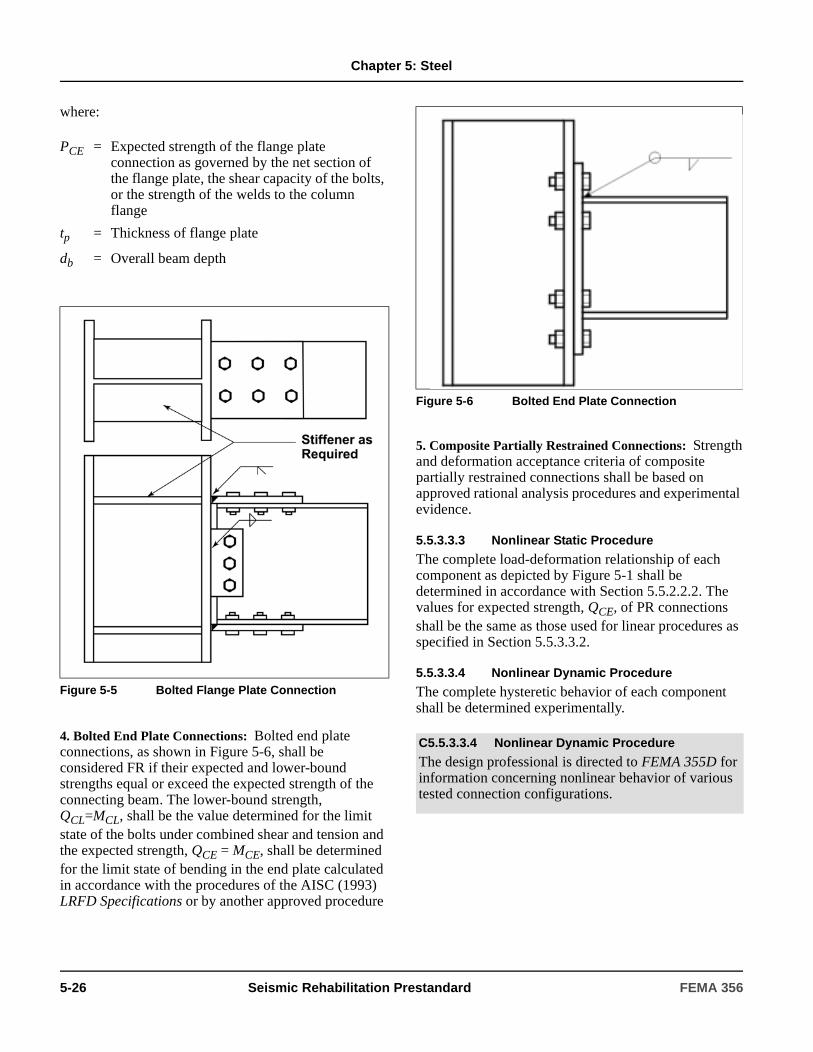
Chapter 5: Steel
where:
4. Bolted End Plate Connections: Bolted end plate connections, as shown in Figure 5-6, shall be considered FR if their expected and lower-bound strengths equal or exceed the expected strength of the connecting beam. The lower-bound strength, QCL=MCL, shall be the value determined for the limit state of the bolts under combined shear and tension and the expected strength, QCE = MCE, shall be determined for the limit state of bending in the end plate calculated in accordance with the procedures of the AISC (1993) LRFD Specifications or by another approved procedure
5. Composite Partially Restrained Connections: Strength and deformation acceptance criteria of composite partially restrained connections shall be based on approved rational analysis procedures and experimental evidence.
5.5.3.3.3 Nonlinear Static Procedure
The complete load-deformation relationship of each component as depicted by Figure 5-1 shall be determined in accordance with Section 5.5.2.2.2. The values for expected strength, QCE, of PR connections shall be the same as those used for linear procedures as specified in Section 5.5.3.3.2.
5.5.3.3.4 Nonlinear Dynamic Procedure
The complete hysteretic behavior of each component shall be determined experimentally.
PCE = Expected strength of the flange plate connection as governed by the net section of the flange plate, the shear capacity of the bolts, or the strength of the welds to the column flange
tp = Thickness of flange plate
db = Overall beam depth
Figure 5-5 Bolted Flange Plate Connection
Figure 5-6 Bolted End Plate Connection
C5.5.3.3.4 Nonlinear Dynamic Procedure
The design professional is directed to FEMA 355D for information concerning nonlinear behavior of various tested connection configurations.
5-26 Seismic Rehabilitation Prestandard FEMA 356

Chapter 5: Steel
5.5.3.4 Acceptance Criteria
5.5.3.4.1 General
Component acceptance criteria shall be computed in accordance with the general requirements of Section 5.4.2 and the specific requirements of this section.
5.5.3.4.2 Linear Static and Dynamic Procedures
Design actions shall be compared with design strengths in accordance with Section 3.4.2. m-factors for steel components and connections of PR frames shall be selected from Table 5-5. Limit states for which no m-factors are provided in Table 5-5 shall be considered force-controlled.
Acceptance criteria for steel beams and columns in PR frames shall be computed in accordance with Section 5.5.2.4.2.
5.5.3.4.3 Nonlinear Static and Dynamic Procedures
Calculated component actions shall satisfy the requirements of Section 3.4.3. Maximum permissible inelastic deformations shall be taken from Tables 5-6 and 5-7.
5.5.3.5 Rehabilitation Measures
PR moment frames that do not meet the acceptance criteria for the selected Rehabilitation Objective shall be rehabilitated. Rehabilitation measures shall meet the requirements of Section 5.4.3 and other provisions of this standard.
5.6 Steel Braced Frames
5.6.1 General
Steel braced frames shall be defined as those frames that develop seismic resistance primarily through axial forces in the components.
Modeling procedures and rehabilitation measures for concentric braced frames and eccentric braced frames shall be as specified in Sections 5.6.2 and 5.6.3, respectively. Components of concentric and eccentric braced frames shall include columns, beams, braces, and connections. Eccentric braced frames shall also include link beam components.
C5.5.3.4.1 General
The strength and behavior of partially restrained steel moment-resisting frames is typically governed by the connections. The design professional is urged to consider the acceptance criteria for the mechanism that controls the system.
C5.5.3.5 Rehabilitation Measures
The rehabilitation measures for FR moment frames described in C5.5.2.5 may be effective for PR moment frames as well. PR moment frames are often too flexible to provide adequate seismic performance. Adding concentric or eccentric bracing, or reinforced concrete or masonry infills, may be a cost-effective rehabilitation measure.
Connections in PR moment frames are usually components that are weak, flexible, or both. Connections may be rehabilitated by replacing rivets with high-strength bolts, adding weldment to supplement rivets or bolts, or welding stiffeners to connection pieces or combinations of these measures. Refer to FEMA 351 for additional information concerning the rehabilitation of PR moment frames.
C5.6.1 General
Steel braced frames act as vertical trusses where the columns are the chords and the beams and braces are the web members.
Components can be either bare steel, steel with a nonstructural coating for fire protection, or steel with concrete or masonry encasement.
FEMA 356 Seismic Rehabilitation Prestandard 5-27
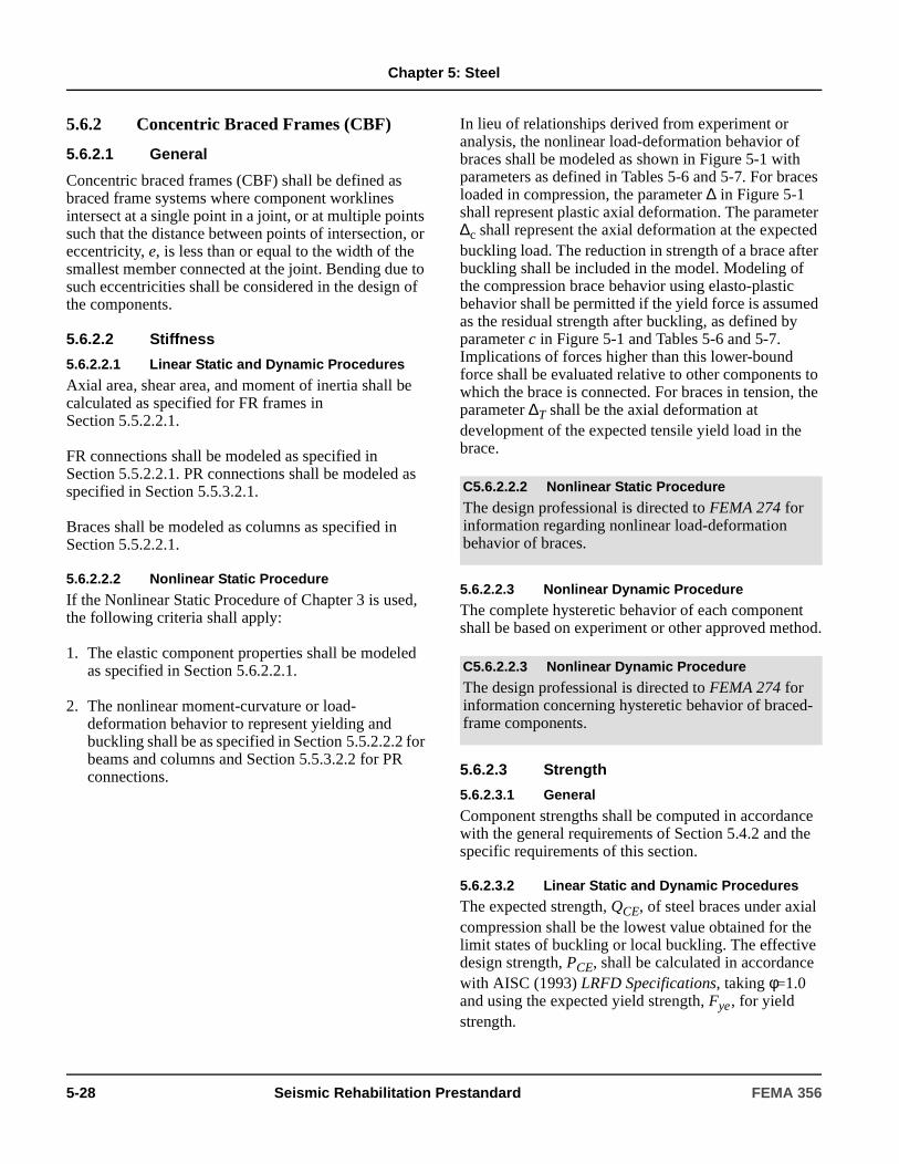
Chapter 5: Steel
5.6.2 Concentric Braced Frames (CBF)
5.6.2.1 General
Concentric braced frames (CBF) shall be defined as braced frame systems where component worklines intersect at a single point in a joint, or at multiple points such that the distance between points of intersection, or eccentricity, e, is less than or equal to the width of the smallest member connected at the joint. Bending due to such eccentricities shall be considered in the design of the components.
5.6.2.2 Stiffness
5.6.2.2.1 Linear Static and Dynamic Procedures
Axial area, shear area, and moment of inertia shall be calculated as specified for FR frames in Section 5.5.2.2.1.
FR connections shall be modeled as specified in Section 5.5.2.2.1. PR connections shall be modeled as specified in Section 5.5.3.2.1.
Braces shall be modeled as columns as specified in Section 5.5.2.2.1.
5.6.2.2.2 Nonlinear Static Procedure
If the Nonlinear Static Procedure of Chapter 3 is used, the following criteria shall apply:
1. The elastic component properties shall be modeled as specified in Section 5.6.2.2.1.
2. The nonlinear moment-curvature or load-deformation behavior to represent yielding and buckling shall be as specified in Section 5.5.2.2.2 for beams and columns and Section 5.5.3.2.2 for PR connections.
In lieu of relationships derived from experiment or analysis, the nonlinear load-deformation behavior of braces shall be modeled as shown in Figure 5-1 with parameters as defined in Tables 5-6 and 5-7. For braces loaded in compression, the parameter ∆ in Figure 5-1 shall represent plastic axial deformation. The parameter ∆c shall represent the axial deformation at the expected buckling load. The reduction in strength of a brace after buckling shall be included in the model. Modeling of the compression brace behavior using elasto-plastic behavior shall be permitted if the yield force is assumed as the residual strength after buckling, as defined by parameter c in Figure 5-1 and Tables 5-6 and 5-7. Implications of forces higher than this lower-bound force shall be evaluated relative to other components to which the brace is connected. For braces in tension, the parameter ∆T shall be the axial deformation at development of the expected tensile yield load in the brace.
5.6.2.2.3 Nonlinear Dynamic Procedure
The complete hysteretic behavior of each component shall be based on experiment or other approved method.
5.6.2.3 Strength
5.6.2.3.1 General
Component strengths shall be computed in accordance with the general requirements of Section 5.4.2 and the specific requirements of this section.
5.6.2.3.2 Linear Static and Dynamic Procedures
The expected strength, QCE, of steel braces under axial compression shall be the lowest value obtained for the limit states of buckling or local buckling. The effective design strength, PCE, shall be calculated in accordance with AISC (1993) LRFD Specifications, taking φ=1.0 and using the expected yield strength, Fye, for yield strength.
C5.6.2.2.2 Nonlinear Static Procedure
The design professional is directed to FEMA 274 for information regarding nonlinear load-deformation behavior of braces.
C5.6.2.2.3 Nonlinear Dynamic Procedure
The design professional is directed to FEMA 274 for information concerning hysteretic behavior of braced-frame components.
5-28 Seismic Rehabilitation Prestandard FEMA 356
Chapter 5: Steel
For common cross bracing configurations where both braces cross at their midpoints and are attached to a common gusset plate, the effective length of each brace shall be taken as 0.5 times the total length of the brace including gusset plates for both axes of buckling. For other bracing configurations (chevron, V, single brace), the length shall be taken as the total length of the brace including gusset plates, and the effective length shall be taken as 0.8 times the total length for in-plane buckling and 1.0 times the total length for out-of-plane buckling.
The expected strength, QCE, of steel braces in tension shall be calculated as for columns, in accordance with Section 5.5.2.3.2.
Expected, QCE, and lower bound, QCL, strengths of beams and columns shall be calculated as for FR beams and columns in Section 5.5.2.3. Strength of beams with non-negligible axial load shall be as calculated for FR columns.
The lower-bound strength of brace connections shall be calculated in accordance with the AISC (1993) LFRD Specifications, taking φ=1.0 and using the lower-bound yield strength, FyLB, for yield strength.
5.6.2.3.3 Nonlinear Static Procedure
In lieu of relationships derived by experiment or analysis, the complete load-deformation behavior of each component as depicted by Figure 5-1 shall be determined in accordance with Section 5.5.2.2.2. The values for expected strength, QCE, shall as specified in Section 5.6.2.3.2 for linear procedures.
5.6.2.3.4 Nonlinear Dynamic Procedure
The complete hysteretic behavior of each component shall be determined experimentally.
5.6.2.4 Acceptance Criteria
5.6.2.4.1 General
Component acceptance criteria shall be computed in accordance with the general requirements of Section 5.4.2 and the specific requirements of this section.
Axial tension and compression in braces shall be considered deformation-controlled. Actions on beams and columns with non-negligible axial load shall be considered force- or deformation-controlled as determined for FR frame columns in Section 5.5.2.4. Compression, tension, shear, and bending actions on brace connections including gusset plates, bolts, welds, and other connectors shall be considered force-controlled.
5.6.2.4.2 Linear Static and Dynamic Procedures
Design actions shall be compared with design strengths in accordance with Section 3.4.2. m-factors for steel components shall be selected from Table 5-5.
Stitch plates for built-up members shall be spaced such that the largest slenderness ratio of the components of the brace does not exceed 0.4 times the governing slenderness ratio of the brace as a whole. The stitches for compression members shall be able to transfer the maximum force in one element to adjacent elements. If not, stitch plates shall be added, or the m-factors in Table 5-4 shall be reduced by 50%, but need not be taken less than 1.0.
5.6.2.4.3 Nonlinear Static and Dynamic Procedures
Calculated component actions shall satisfy the requirements of Section 3.4.3. Deformations limits shall be taken from Tables 5-6 and 5-7.
5.6.2.5 Rehabilitation Measures
Concentric braced frame components that do meet not the acceptance criteria for the selected Rehabilitation Objective shall be rehabilitated. Rehabilitation measures shall meet the requirements of Section 5.4.3 and other provisions of this standard.
C5.6.2.3.4 Nonlinear Dynamic Procedure
The design professional is directed to FEMA 274 for information concerning hysteretic behavior of braced frame components.
C5.6.2.5 Rehabilitation Measures
The rehabilitation measures for FR moment frames described in Section C5.5.2.5 may be effective for braced frames. Other modifications which may be effective include replacement or modification of connections that are insufficient in strength and/or ductility, and encasement of columns in concrete to improve their performance.
FEMA 356 Seismic Rehabilitation Prestandard 5-29
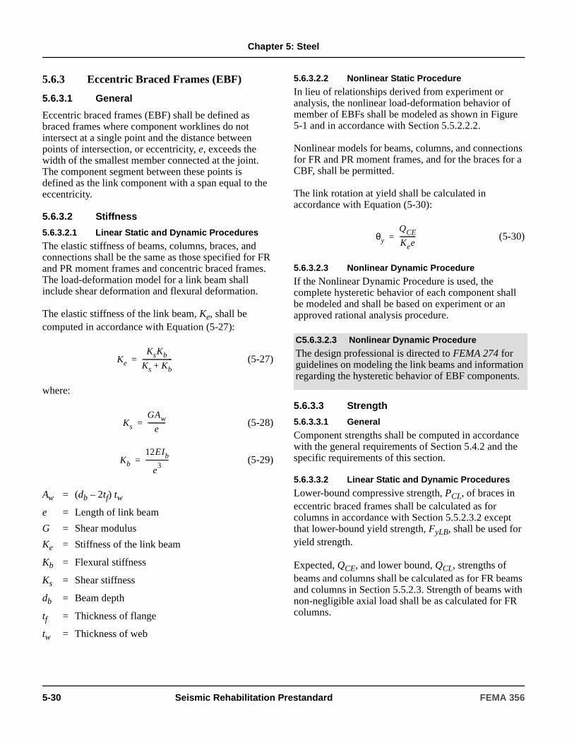
Chapter 5: Steel
5.6.3 Eccentric Braced Frames (EBF)
5.6.3.1 General
Eccentric braced frames (EBF) shall be defined as braced frames where component worklines do not intersect at a single point and the distance between points of intersection, or eccentricity, e, exceeds the width of the smallest member connected at the joint. The component segment between these points is defined as the link component with a span equal to the eccentricity.
5.6.3.2 Stiffness
5.6.3.2.1 Linear Static and Dynamic Procedures
The elastic stiffness of beams, columns, braces, and connections shall be the same as those specified for FR and PR moment frames and concentric braced frames. The load-deformation model for a link beam shall include shear deformation and flexural deformation.
The elastic stiffness of the link beam, Ke, shall be computed in accordance with Equation (5-27):
(5-27)
where:
(5-28)
(5-29)
5.6.3.2.2 Nonlinear Static Procedure
In lieu of relationships derived from experiment or analysis, the nonlinear load-deformation behavior of member of EBFs shall be modeled as shown in Figure 5-1 and in accordance with Section 5.5.2.2.2.
Nonlinear models for beams, columns, and connections for FR and PR moment frames, and for the braces for a CBF, shall be permitted.
The link rotation at yield shall be calculated in accordance with Equation (5-30):
(5-30)
5.6.3.2.3 Nonlinear Dynamic Procedure
If the Nonlinear Dynamic Procedure is used, the complete hysteretic behavior of each component shall be modeled and shall be based on experiment or an approved rational analysis procedure.
5.6.3.3 Strength
5.6.3.3.1 General
Component strengths shall be computed in accordance with the general requirements of Section 5.4.2 and the specific requirements of this section.
5.6.3.3.2 Linear Static and Dynamic Procedures
Lower-bound compressive strength, PCL, of braces in eccentric braced frames shall be calculated as for columns in accordance with Section 5.5.2.3.2 except that lower-bound yield strength, FyLB, shall be used for yield strength.
Expected, QCE, and lower bound, QCL, strengths of beams and columns shall be calculated as for FR beams and columns in Section 5.5.2.3. Strength of beams with non-negligible axial load shall be as calculated for FR columns.
Aw = (db – 2tf) tw
e = Length of link beam
G = Shear modulus
Ke = Stiffness of the link beam
Kb = Flexural stiffness
Ks = Shear stiffness
db = Beam depth
tf = Thickness of flange
tw = Thickness of web
Ke
KsKb
Ks Kb+-------------------=
Ks
GAw
e-----------=
Kb
12EIb
e3
---------------=
C5.6.3.2.3 Nonlinear Dynamic Procedure
The design professional is directed to FEMA 274 for guidelines on modeling the link beams and information regarding the hysteretic behavior of EBF components.
θy
QCE
Kee----------=
5-30 Seismic Rehabilitation Prestandard FEMA 356

Chapter 5: Steel
The lower-bound strength of brace connections shall be calculated in accordance with AISC (1993) LRFD Specifications, taking φ=1.0 and using the lower-bound yield strength, FyLB, for yield strength.
The strength of the link beam shall be governed by shear, flexure, or the combination of shear and flexure. MCE shall be taken as the expected moment capacity and VCE shall be taken as 0.6 FyeAw.
If , Equation (5-31) shall be used to compute
the expected strength of the link beam:
(5-31)
If , Equation (5-32) shall be used to compute
the expected strength of the link beam:
(5-32)
Linear interpolation between Equations (5-31) and (5-32) shall be used for intermediate values of e.
5.6.3.3.3 Nonlinear Static Procedure
Strengths for EBFs shall be the same as those specified in Section 5.6.2.3.3 for CBFs. In lieu of relationships derived from experiment or analysis, the load-deformation behavior of each component, as depicted by Figure 5-1, shall be determined in accordance with Section 5.6.3.2.2.
5.6.3.3.4 Nonlinear Dynamic Procedure
The complete hysteretic behavior of each component shall be determined experimentally.
5.6.3.4 Acceptance Criteria
5.6.3.4.1 General
Component acceptance criteria shall be computed in accordance with the general requirements of Section 5.4.2 and the specific requirements of this section.
Shear and flexure in link beams shall be considered deformation-controlled actions. All other actions, and actions on other EBF components, shall be considered force-controlled. Compression, tension, shear, and bending actions on brace connections including gusset plates, bolts, welds, and other connectors shall be considered force-controlled.
5.6.3.4.2 Linear Static and Dynamic Procedures
Design actions shall be compared with design strengths in accordance with Section 3.4.2. m-factors for steel components shall be selected from Table 5-5.
Link beams shall conform to the requirements of the AISC (1997) Seismic Provisions with regard to detailing. The brace connecting to a link beam shall be designed for 1.25 times the link strength to ensure link yielding without brace or column buckling. Where the link beam is attached to the column flange with full-pen welds, the provisions for these connections shall be the same as for FR frame full-pen connections. m-factors for flexure and shear in link beams shall be taken from Table 5-5.
5.6.3.4.3 Nonlinear Static and Dynamic Procedures
Calculated component actions shall satisfy the requirements of Section 3.4.3. Deformations limits shall be taken from Tables 5-6 and 5-7.
e1.6MCE
VCE-------------------≤
QCE VCE 0.6FyeAw= =
e2.6MCE
VCE------------------->
QCE 2MCE
e-----------=
C5.6.3.4.2 Linear Static and Dynamic Procedures
The acceptance criteria for full-penetration welded beam-to-column connections is based on testing of typical moment frame proportioning and span ratios.
FEMA 356 Seismic Rehabilitation Prestandard 5-31

Chapter 5: Steel
5.6.3.5 Rehabilitation Measures
Eccentric braced frame components that do not meet the acceptance criteria for the selected Rehabilitation Objective shall be rehabilitated. Rehabilitation measures shall meet the requirements of Section 5.4.3 and other provisions of this standard.
5.7 Steel Plate Shear Walls
5.7.1 General
A steel plate shear wall, with or without perforations, shall be provided with boundary members on all four sides and shall be welded to these boundary elements. The steel plate walls shall be designed to resist seismic loads acting alone or in conjunction with other existing lateral load resisting elements. The boundary elements shall be evaluated as beams and/or columns.
5.7.2 Stiffness
5.7.2.1 Linear Static and Dynamic Procedures
Use of a plane stress finite element with beams and col-umns as boundary elements to analyze a steel plate shear wall shall be permitted. The global stiffness of the wall, Kw, shall be calculated in accordance with Equa-tion (5-33) unless another method based on principles of mechanics is used.
(5-33)
where:
5.7.2.2 Nonlinear Static Procedure
The elastic stiffness of the load-deformation relationship for the wall shall be as specified in Section 5.7.2.1. The complete nonlinear load-deformation relationship shall be based on experiment or approved rational analysis. Alternatively, use of the generalized load-deformation relationship shown in Figure 5-1, as specified in Section 5.5.2.2.2, shall be permitted.
5.7.2.3 Nonlinear Dynamic Procedure
The complete hysteretic behavior of each component shall be modeled by a rational procedure verified by experiment.
5.7.3 Strength
5.7.3.1 General
Component strengths shall be computed in accordance with the general requirements of Section 5.4.2 and the specific requirements of this section.
C5.6.3.5 Rehabilitation Measures
The rehabilitation measures described in C5.4.2.4 for FR moment frames and in C5.5.2.4 for CBFs may be effective for many of the beams, columns, and braces. Cover plates and/or stiffeners may be effective in rehabilitating these components. The strength of the link may be increased by adding cover plates to the beam flange(s), adding doubler plates or stiffeners to the web, or changing the brace configuration.
C5.7.1 General
A steel plate wall develops its seismic resistance through shear stress in the plate wall.
Although steel plate walls are not common, they have been used to rehabilitate a few essential structures where Immediate Occupancy and operation of a facility is mandatory after a large earthquake. Due to their stiffness, the steel plate walls attract much of the seismic shear. It is essential that the new load paths be carefully established.
The provisions for steel plate walls in this standard assume that the plates are sufficiently stiffened to prevent buckling. The design professional is referred to Timler (2000) for additional information regarding the behavior and design of steel plate shear walls.
G = Shear modulus of steela = Clear width of wall between columnsh = Clear height of wall between beamstw = Thickness of plate wall
C5.7.2.3 Nonlinear Dynamic Procedure
This procedure is not recommended in most cases.
Kw
Ga tw
h---------------=
5-32 Seismic Rehabilitation Prestandard FEMA 356
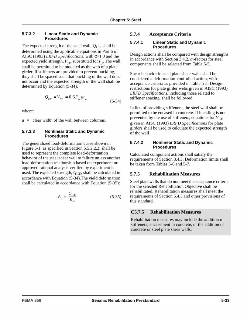
Chapter 5: Steel
5.7.3.2 Linear Static and Dynamic Procedures
The expected strength of the steel wall, QCE, shall be determined using the applicable equations in Part 6 of AISC (1993) LRFD Specifications, with φ=1.0 and the expected yield strength, Fye, substituted for Fy. The wall shall be permitted to be modeled as the web of a plate girder. If stiffeners are provided to prevent buckling, they shall be spaced such that buckling of the wall does not occur and the expected strength of the wall shall be determined by Equation (5-34):
(5-34)
where:
5.7.3.3 Nonlinear Static and Dynamic Procedures
The generalized load-deformation curve shown in Figure 5-1, as specified in Section 5.5.2.2.2, shall be used to represent the complete load-deformation behavior of the steel shear wall to failure unless another load-deformation relationship based on experiment or approved rational analysis verified by experiment is used. The expected strength, QCE, shall be calculated in accordance with Equation (5-34).The yield deformation shall be calculated in accordance with Equation (5-35):
(5-35)
5.7.4 Acceptance Criteria
5.7.4.1 Linear Static and Dynamic Procedures
Design actions shall be compared with design strengths in accordance with Section 3.4.2. m-factors for steel components shall be selected from Table 5-5.
Shear behavior in steel plate shear walls shall be considered a deformation-controlled action, with acceptance criteria as provided in Table 5-5. Design restrictions for plate girder webs given in AISC (1993) LRFD Specifications, including those related to stiffener spacing, shall be followed.
In lieu of providing stiffeners, the steel wall shall be permitted to be encased in concrete. If buckling is not prevented by the use of stiffeners, equations for VCE given in AISC (1993) LRFD Specifications for plate girders shall be used to calculate the expected strength of the wall.
5.7.4.2 Nonlinear Static and Dynamic Procedures
Calculated component actions shall satisfy the requirements of Section 3.4.3. Deformation limits shall be taken from Tables 5-6 and 5-7.
5.7.5 Rehabilitation Measures
Steel plate walls that do not meet the acceptance criteria for the selected Rehabilitation Objective shall be rehabilitated. Rehabilitation measures shall meet the requirements of Section 5.4.3 and other provisions of this standard.
a = clear width of the wall between columns.
wyeCECEatFVQ 6.0==
∆y
QCE
Kw-----------=
C5.7.5 Rehabilitation Measures
Rehabilitation measures may include the addition of stiffeners, encasement in concrete, or the addition of concrete or steel plate shear walls.
FEMA 356 Seismic Rehabilitation Prestandard 5-33

Chapter 5: Steel
5.8 Steel Frames with InfillsSteel frames with partial or complete infills of reinforced concrete or reinforced or unreinforced masonry shall be evaluated considering the combined stiffness of the steel frame and infill material.
The engineering properties and acceptance criteria for the infill walls shall comply with the requirements in Chapter 6 for concrete and Chapter 7 for masonry. Infill walls and frames shall be considered to carry the seismic force in composite action, considering the relative stiffness of each element, until complete failure of the walls has occurred. The interaction between the steel frame and infill shall be considered using procedures specified in Chapter 6 for concrete frames with infill. The analysis of each component shall be done in stages, considering the effects of interaction between the elements and carried through each performance level. At the point where the infill has been deemed to fail, as determined by the acceptance criteria specified in Chapter 6 or Chapter 7, the wall shall be removed from the analytical model. The analysis shall be resumed on the bare steel frame taking into consideration any vertical discontinuity created by the degraded wall. At this point, the engineering properties and acceptance criteria for the frame, as specified in Section 5.5, shall apply.
C5.8 Steel Frames with InfillsSeismic evaluation of infill walls is required because, in many cases, these walls are unreinforced or lightly reinforced, and their strength and ductility may be inadequate. Before the loss of the wall, the steel frame adds confining pressure to the wall and enhances its resistance. The actual effective forces on the steel frame components, however, are probably minimal. As the frame components attempt to develop force they deform and the stiffer concrete or masonry components on the far side of the member pick up load. However, beam end connections, column splices, and steel frame connections at the foundation should be investigated for forces due to interaction with the infill similar to procedures specified for concrete frames in Chapter 6.
The stiffness and resistance provided by concrete and/or masonry infills may be much larger than the stiffness of the steel frame acting alone with or without composite actions. Gaps or incomplete contact between the steel frame and the infill may negate some or all of this stiffness. These gaps may be between the wall and columns of the frame or between the wall and the top beam enclosing the frame. Different strength and stiffness conditions must be expected with different discontinuity types and locations. Therefore, the presence of any gaps or discontinuities between the infill walls and the frame must be determined and considered in the design and rehabilitation process. The resistance provided by infill walls may also be included if proper evaluation of the connection and interaction between the wall and the frame is made and if the strength, ductility, and properties of the wall are properly included.
The stiffness provided by infill masonry walls is excluded from the design and rehabilitation process unless integral action between the steel frame and the wall is verified. If complete or partial interaction between the wall and frame is verified, the stiffness is increased accordingly. The seismic performance of unconfined masonry walls is far inferior to that of confined masonry walls; therefore, the resistance of the attached wall can be used only if strong evidence as to its strength, ductility, and interaction with the steel frame is provided.
5-34 Seismic Rehabilitation Prestandard FEMA 356

Chapter 5: Steel
Table 5-5 Acceptance Criteria for Linear Procedures—Structural Steel Components
m-factors for Linear Procedures1
IO
Primary Secondary
Component/Action LS CP LS CP
Beams – flexure
a.
and 2 6 8 10 12
b.
or 1.25 2 3 3 4
c. Other
Linear interpolation between the values on lines a and b for both flange slenderness (first term) and web slenderness (second term) shall be performed, and the lowest
resulting value shall be used
Columns – flexure 12, 13
For P/PCL < 0.20
a.
and 2 6 8 10 12
b.
or 1.25 1.25 2 2 3
c. Other
Linear interpolation between the values on lines a and b for both flange slenderness (first term) and web slenderness (second term) shall be performed, and the lowest
resulting value shall be used
bf2tf------ 52
Fye
------------≤
htw----- 418
Fye
------------≤
bf2tf------ 65
Fye
------------≥
htw----- 640
Fye
------------≥
bf2tf------ 52
Fye
------------≤
htw----- 300
Fye
------------≤
bf2tf------ 65
Fye
------------≥
htw----- 460
Fye
------------≥
FEMA 356 Seismic Rehabilitation Prestandard 5-35

Chapter 5: Steel
For 0.2 < P/PCL < 0.50
a.
and 1.25 —2 —3 —4 —5
b.
or 1.25 1.25 1.5 2 2
c. OtherLinear interpolation between the values on lines a and b for both flange slenderness (first term) and web slenderness (second term) shall be performed, and the lowest
resulting value shall be used
Column Panel Zones – Shear 1.5 8 11 12 12
Fully Restrained Moment Connections15
WUF14 1.0 4.3-0.083d 3.9-0.043d 4.3-0.048d 5.5-0.064d
Bottom haunch in WUF with slab 1.6 2.7 3.4 3.8 4.7
Bottom haunch in WUF without slab 1.3 2.1 2.5 2.8 3.3
Welded cover plate in WUF14 2.4-0.030d 4.3-0.067d 5.4-0.090d 5.4-0.090d 6.9-0.118d
Improved WUF-bolted web14 1.4-0.008d 2.3-0.021d 3.1-0.032d 4.9-0.048d 6.2-0.065d
Improved WUF-welded web 2.0 4.2 5.3 5.3 6.7
Free flange14 2.7-0.032d 6.3-0.098d 8.1-0.129d 8.4-0.129d 11.0-0.172d
Reduced beam section14 2.2-0.008d 4.9-0.025d 6.2-0.032d 6.5-0.025d 8.4-0.032d
Welded flange plates
a. Flange plate net section 1.7 3.3 4.1 5.7 7.3
b. Other limit states force-controlled
Welded bottom haunch 1.6 3.1 3.8 4.6 5.9
Welded top and bottom haunches 1.6 3.1 3.9 4.7 6.0
Welded cover-plated flanges 1.7 2.8 3.4 3.4 4.2
Table 5-5 Acceptance Criteria for Linear Procedures—Structural Steel Components (continued)
m-factors for Linear Procedures1
IO
Primary Secondary
Component/Action LS CP LS CP
bf2tf------ 52
Fye
------------≤
htw----- 260
Fye
------------≤
bf2tf------ 65
Fye
------------≥
htw----- 400
Fye
------------≥
5-36 Seismic Rehabilitation Prestandard FEMA 356

Chapter 5: Steel
Partially Restrained Moment Connections
Top and bottom clip angle8
a. Shear failure of rivet or bolt (Limit State 1)9
1.5 4 6 6 8
b. Tension failure of horizontal leg of angle (Limit State 2)
1.25 1.5 2 1.5 2
c. Tension failure of rivet or bolt (Limit State 3)9
1.25 1.5 2.5 4 4
d. Flexural failure of angle (Limit State 4)
2 5 7 7 14
Double split tee8
a. Shear failure of rivet or bolt (Limit State 1)9
1.5 4 6 6 8
b. Tension failure of rivet or bolt (Limit State 2)9
1.25 1.5 2.5 4 4
c. Tension failure of split tee stem (Limit State 3)
1.25 1.5 2 1.5 2
d. Flexural failure of split tee (Limit State 4)
2 5 7 7 14
Bolted flange plate8
a. Failure in net section of flange plate or shear failure of bolts or rivets9
1.5 4 5 4 5
b. Weld failure or tension failure on gross section of plate
1.25 1.5 2 1.5 2
Bolted end plate
a. Yield of end plate 2 5.5 7 7 7
b. Yield of bolts 1.5 2 3 4 4
c. Failure of weld 1.25 1.5 2 3 3
Composite top and clip angle bottom 8
a. Failure of deck reinforcement 1.25 2 3 4 6
b. Local flange yielding and web crippling of column
1.5 4 6 5 7
c. Yield of bottom flange angle 1.5 4 6 6 7
d. Tensile yield of rivets or bolts at column flange
1.25 1.5 2.5 2.5 3.5
e. Shear yield of beam flange connections
1.25 2.5 3.5 3.5 4.5
Shear connection with slab14 1.6-0.005dbg -- -- 13.0-0.290dbg 17.0-0.387dbg
Shear connection without slab14 4.9-0.097dbg -- -- 13.0-0.290dbg 17.0-0.387dbg
Table 5-5 Acceptance Criteria for Linear Procedures—Structural Steel Components (continued)
m-factors for Linear Procedures1
IO
Primary Secondary
Component/Action LS CP LS CP
FEMA 356 Seismic Rehabilitation Prestandard 5-37

Chapter 5: Steel
EBF Link Beam7, 10
a. 1.5 9 13 13 15
b. Same as for beams.
c. Linear interpolation shall be used.
Braces in Compression (except EBF braces)
a. Double angles buckling in-plane
1.25 6 8 7 9
b. Double angles buckling out-of-plane
1.25 5 7 6 8
c. W or I shape 1.25 6 8 6 8
d. Double channels buckling in-plane
1.25 6 8 7 9
e. Double channels buckling out-of-plane
1.25 5 7 6 8
f. Concrete-filled tubes 1.25 5 7 5 7
g. Rectangular cold-formed tubes
1. 1.25 5 7 5 7
2. 1.25 2 3 2 3
3. Linear interpolation shall be used.
h. Circular hollow tubes
1. 1.25 5 7 5 7
Table 5-5 Acceptance Criteria for Linear Procedures—Structural Steel Components (continued)
m-factors for Linear Procedures1
IO
Primary Secondary
Component/Action LS CP LS CP
e1.6 MCE
VCE-------------------≤
e2.6 MCE
VCE-------------------≥
1.6 MCE
VCE------------------- e
2.6 MCE
VCE-------------------< <
yFt
d 90≤
yFt
d 190≥
yFt
d
yF
19090≤≤
yFt
d 1500≤
5-38 Seismic Rehabilitation Prestandard FEMA 356

Chapter 5: Steel
2. 1.25 2 3 2 3
3. Linear interpolation shall be used.
Braces in Tension (except EBF braces)16
1.25 6 8 8 10
Beams, Columns in Tension (except EBF beams, columns)
1.25 3 5 6 7
Steel Plate Shear Walls11 1.5 8 12 12 14
Diaphragm Components
Diaphragm shear yielding or panel or plate buckling
1.25 2 3 2 3
Diaphragm chords and collectors—full lateral support
1.25 6 8 6 8
Diaphragm chords and collectors—limited lateral support
1.25 2 3 2 3
1. For built-up members where the lacing plates do not meet the requirements of Section 5.6.2.4.2, divide m-factors by 2.0, but values need not be less than 1.0.
2. m=9(1-1.7 P/PCL).
3. m=12(1-1.7 P/PCL).
4. m=15(1-1.7 P/PCL).
5. m=18(1-1.7 P/PCL).
6. Not used.
7. Values are for link beams with three or more web stiffeners. If no stiffeners, divide values by 2.0, but values need not be less than 1.25. Linear interpolation shall be used for one or two stiffeners.
8. Web plate or stiffened seat shall be considered to carry shear. Without shear connection, action shall not be classified as secondary. If db > 18 inches, multiply m-factors by 18/db, but values need not be less than 1.0.
9. For high-strength bolts, divide values by 2.0, but values need not be less than 1.25.
10. Assumes ductile detailing for flexural link, in accordance with AISC (1995) LRFD Specifications.
11. Applicable if stiffeners, or concrete backing, is provided to prevent buckling.
12. Columns in moment or braced frames shall be permitted to be designed for the maximum force delivered by connecting members. For rectangular or square columns, replace bt /2tf with b/t, replace 52 with 110, and replace 65 with 190.
13. Columns with P/PCL > 0.5 shall be considered force-controlled.
14. d is the beam depth; dbg is the depth of the bolt group.
15. Tabulated values shall be modified as indicated in Section 5.5.2.4.2, item 4.
16. For tension-only bracing, m-factors shall be divided by 2.0.
Table 5-5 Acceptance Criteria for Linear Procedures—Structural Steel Components (continued)
m-factors for Linear Procedures1
IO
Primary Secondary
Component/Action LS CP LS CP
yFt
d 6000≥
yFt
d
yF
60001500≤≤
FEMA 356 Seismic Rehabilitation Prestandard 5-39
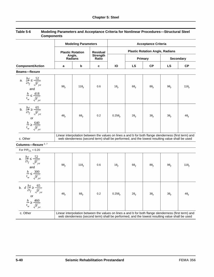
Chapter 5: Steel
Table 5-6 Modeling Parameters and Acceptance Criteria for Nonlinear Procedures—Structural Steel Components
Component/Action
Modeling Parameters Acceptance Criteria
Plastic RotationAngle,
Radians
Residual Strength
Ratio
Plastic Rotation Angle, Radians
IO
Primary Secondary
a b c LS CP LS CP
Beams—flexure
a.
and 9θy 11θy 0.6 1θy 6θy 8θy 9θy 11θy
b.
or 4θy 6θy 0.2 0.25θy 2θy 3θy 3θy 4θy
c. Other
Linear interpolation between the values on lines a and b for both flange slenderness (first term) and web slenderness (second term) shall be performed, and the lowest resulting value shall be used
Columns—flexure 2, 7
For P/PCL < 0.20
a.
and 9θy 11θy 0.6 1θy 6θy 8θy 9θy 11θy
b.
or 4θy 6θy 0.2 0.25θy 2θy 3θy 3θy 4θy
c. Other Linear interpolation between the values on lines a and b for both flange slenderness (first term) and web slenderness (second term) shall be performed, and the lowest resulting value shall be used
bf2tf------ 52
Fye
------------≤
htw----- 418
Fye
------------≤
bf2tf------ 65
Fye
------------≥
htw----- 640
Fye
------------≥
bf2tf------ 52
Fye
------------≤
htw----- 300
Fye
------------≤
bf2tf------ 65
Fye
------------≥d
htw----- 460
Fye
------------≥
5-40 Seismic Rehabilitation Prestandard FEMA 356

Chapter 5: Steel
For 0.2 < P/PCL < 0.50
a.
and — 3 — 4 0.2 0.25θy — 5 — 3 — 6 — 4
b.
or 1θy 1.5θy 0.2 0.25θy 0.5θy 0.8θy 1.2θy 1.2θy
c. Other
Linear interpolation between the values on lines a and b for both flange slenderness (first term) and web slenderness (second term) shall be performed, and the lowest resulting value shall be used
Column Panel Zones 12θy 12θy 1.0 1θy 8θy 11θy 12θy 12θy
Fully Restrained Moment Connections13
WUF12 0.051-0.0013d 0.043-0.0006d 0.2 0.0128-0.0003d
0.0337-0.0009d
0.0284-0.0004d
0.0323-0.0005d
0.043-0.0006d
Bottom haunch in WUF with slab
0.026 0.036 0.2 0.0065 0.0172 0.0238 0.0270 0.036
Bottom haunch in WUF without slab
0.018 0.023 0.2 0.0045 0.0119 0.0152 0.0180 0.023
Welded cover plate in WUF12
0.056-0.0011d 0.056-0.0011d 0.2 0.0140-0.0003d
0.0319-0.0006d
0.0426-0.0008d
0.0420-0.0008d
0.056-0.0011d
Improved WUF-bolted web12
0.021-0.0003d 0.050-0.0006d 0.2 0.0053-0.0001d
0.0139-0.0002d
0.0210-0.0003d
0.0375-0.0005d
0.050-0.0006d
Improved WUF-welded web 0.041 0.054 0.2 0.0103 0.0312 0.0410 0.0410 0.054
Free flange12 0.067-0.0012d 0.094-0.0016d 0.2 0.0168-0.0003d
0.0509-0.0009d
0.0670-0.0012d
0.0705-0.0012d
0.094-0.0016d
Reduced beam section12 0.050-0.0003d 0.070-0.0003d 0.2 0.0125-0.0001d
0.0380-0.0002d
0.0500-0.0003d
0.0525-0.0002d
0.07-0.0003d
Welded flange plates
a. Flange plate net section
0.03 0.06 0.2 0.0075 0.0228 0.0300 0.0450 0.06
b. Other limit states force-controlled
Welded bottom haunch 0.027 0.047 0.2 0.0068 0.0205 0.0270 0.0353 0.047
Welded top and bottom haunches
0.028 0.048 0.2 0.0070 0.0213 0.0280 0.0360 0.048
Welded cover-plated flanges
0.031 0.031 0.2 0.0078 0.0177 0.0236 0.0233 0.031
Table 5-6 Modeling Parameters and Acceptance Criteria for Nonlinear Procedures—Structural Steel Components (continued)
Component/Action
Modeling Parameters Acceptance Criteria
Plastic RotationAngle,
Radians
Residual Strength
Ratio
Plastic Rotation Angle, Radians
IO
Primary Secondary
a b c LS CP LS CP
bf2tf------ 52
Fye
------------≤
htw----- 260
Fye
------------≤
bf2tf------ 65
Fye
------------≥
htw----- 400
Fye
------------≥
FEMA 356 Seismic Rehabilitation Prestandard 5-41
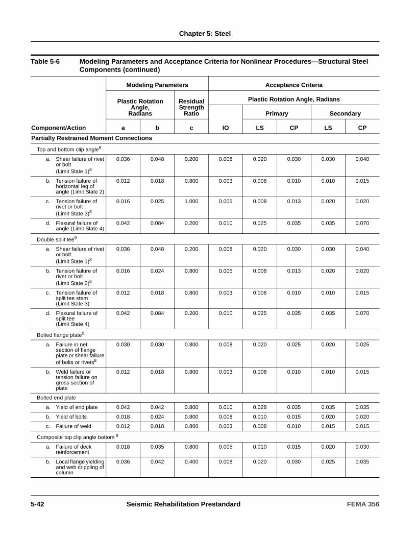
Chapter 5: Steel
Partially Restrained Moment Connections
Top and bottom clip angle9
a. Shear failure of rivet or bolt (Limit State 1)8
0.036 0.048 0.200 0.008 0.020 0.030 0.030 0.040
b. Tension failure of horizontal leg of angle (Limit State 2)
0.012 0.018 0.800 0.003 0.008 0.010 0.010 0.015
c. Tension failure of rivet or bolt (Limit State 3)8
0.016 0.025 1.000 0.005 0.008 0.013 0.020 0.020
d. Flexural failure of angle (Limit State 4)
0.042 0.084 0.200 0.010 0.025 0.035 0.035 0.070
Double split tee9
a. Shear failure of rivet or bolt (Limit State 1)8
0.036 0.048 0.200 0.008 0.020 0.030 0.030 0.040
b. Tension failure of rivet or bolt (Limit State 2)8
0.016 0.024 0.800 0.005 0.008 0.013 0.020 0.020
c. Tension failure of split tee stem (Limit State 3)
0.012 0.018 0.800 0.003 0.008 0.010 0.010 0.015
d. Flexural failure of split tee (Limit State 4)
0.042 0.084 0.200 0.010 0.025 0.035 0.035 0.070
Bolted flange plate9
a. Failure in net section of flange plate or shear failure of bolts or rivets8
0.030 0.030 0.800 0.008 0.020 0.025 0.020 0.025
b. Weld failure or tension failure on gross section of plate
0.012 0.018 0.800 0.003 0.008 0.010 0.010 0.015
Bolted end plate
a. Yield of end plate 0.042 0.042 0.800 0.010 0.028 0.035 0.035 0.035
b. Yield of bolts 0.018 0.024 0.800 0.008 0.010 0.015 0.020 0.020
c. Failure of weld 0.012 0.018 0.800 0.003 0.008 0.010 0.015 0.015
Composite top clip angle bottom 9
a. Failure of deck reinforcement
0.018 0.035 0.800 0.005 0.010 0.015 0.020 0.030
b. Local flange yielding and web crippling of column
0.036 0.042 0.400 0.008 0.020 0.030 0.025 0.035
Table 5-6 Modeling Parameters and Acceptance Criteria for Nonlinear Procedures—Structural Steel Components (continued)
Component/Action
Modeling Parameters Acceptance Criteria
Plastic RotationAngle,
Radians
Residual Strength
Ratio
Plastic Rotation Angle, Radians
IO
Primary Secondary
a b c LS CP LS CP
5-42 Seismic Rehabilitation Prestandard FEMA 356

Chapter 5: Steel
c. Yield of bottom flange angle
0.036 0.042 0.200 0.008 0.020 0.030 0.025 0.035
d. Tensile yield of rivets or bolts at column flange
0.015 0.022 0.800 0.005 0.008 0.013 0.013 0.018
e. Shear yield of beam flange connection
0.022 0.027 0.200 0.005 0.013 0.018 0.018 0.023
Shear connection with slab12
0.029-0.0002dbg
0.15-0.0036dbg 0.400 0.0073-0.0001dbg
-- -- 0.1125-0.0027dbg
0.15-0.0036dbg
Shear connection without slab12
0.15-0.0036dbg 0.15-0.0036dbg 0.400 0.0375-0.0009dbg
-- -- 0.1125-0.0027dbg
0.15-0.0036dbg
EBF Link Beam10, 11
a. 0.15 0.17 0.8 0.005 0.11 0.14 0.14 0.16
b. Same as for beams.
c. Linear interpolation shall be used.
Steel Plate Shear Walls 1 14θy 16θy 0.7 0.5θy 10θy 13θy 13θy 15θy
1. Values are for shear walls with stiffeners to prevent shear buckling.
2. Columns in moment or braced frames shall be permitted to be designed for the maximum force delivered by connecting members. For rectangular or square columns, replace bt /2tf with b/t, replace 52 with 110, and replace 65 with 190.
3. Plastic rotation = 11 (1-1.7 P/PCL) θy.
4. Plastic rotation = 17 (1-1.7 P/PCL) θy.
5. Plastic rotation = 8 (1-1.7 P/PCL) θy.
6. Plastic rotation = 14 (1-1.7 P/PCL) θy.
7. Columns with P/PCL > 0.5 shall be considered force-controlled.
8. For high-strength bolts, divide values by 2.0.
9. Web plate or stiffened seat shall be considered to carry shear. Without shear connection, action shall not be classified as secondary. If beam depth, db > 18 inches, multiply m-factors by 18/db.
10. Deformation is the rotation angle between link and beam outside link or column.
11. Values are for link beams with three or more web stiffeners. If no stiffeners, divide values by 2.0. Linear interpolation shall be used for one or two stiffeners.
12. d is the beam depth; dbg is the depth of the bolt group.
13. Tabulated values shall be modified as indicated in Section 5.5.2.4.2, item 4.
Table 5-6 Modeling Parameters and Acceptance Criteria for Nonlinear Procedures—Structural Steel Components (continued)
Component/Action
Modeling Parameters Acceptance Criteria
Plastic RotationAngle,
Radians
Residual Strength
Ratio
Plastic Rotation Angle, Radians
IO
Primary Secondary
a b c LS CP LS CP
e1.6 MCE
VCE-------------------≤
e2.6 MCE
VCE-------------------≥
.6 MCE
VCE------------------- e
2.6 MCE
VCE-------------------< <
FEMA 356 Seismic Rehabilitation Prestandard 5-43

Chapter 5: Steel
Table 5-7 Modeling Parameters and Acceptance Criteria for Nonlinear Procedures—Structural Steel Components
Modeling Parameters Acceptance Criteria
Component/Action
Plastic Deformation
Residual Strength
Ratio
Plastic Deformation
IO
Primary Secondary
a b c LS CP LS CP
Braces in Compression (except EBF braces)1
a. Double angles buckling in-plane
0.5∆c 9∆c 0.2 0.25∆c 5∆c 7∆c 7∆c 8∆c
b. Double angles buckling out-of-plane
0.5∆c 8∆c 0.2 0.25∆c 4∆c 6∆c 6∆c 7∆c
c. W or I shape 0.5∆c 8∆c 0.2 0.25∆c 5∆c 7∆c 7∆c 8∆c
d. Double channels buckling in-plane
0.5∆c 9∆c 0.2 0.25∆c 5∆c 7∆c 7∆c 8∆c
e. Double channels buckling out-of-plane
0.5∆c 8∆c 0.2 0.25∆c 4∆c 6∆c 6∆c 7∆c
f. Concrete-filled tubes 0.5∆c 7∆c 0.2 0.25∆c 4∆c 6∆c 6∆c 7∆c
g. Rectangular cold-formed tubes
1. 0.5∆c 7∆c 0.4 0.25∆c 4∆c 6∆c 6∆c 7∆c
2. 0.5∆c 3∆c 0.2 0.25∆c 1∆c 2∆c 2∆c 3∆c
3. Linear interpolation shall be used.
h. Circular hollow tubes
1.0.5∆c 9∆c 0.4 0.25∆c 4∆c 6∆c 5∆c 8∆c
2. 0.5∆c 3∆c 0.2 0.25∆c 1∆c 2∆c 2∆c 3∆c
3. Linear interpolation shall be used.
Braces in Tension
(except EBF braces)2 11∆T 14∆T 0.8 0.25∆T 7∆T 9∆T 11∆T 13∆T
Beams, Columns in Tension (except EBF beams, columns)2
5∆T 7∆T 1.0 0.25∆T 3∆T 5∆T 6∆T 7∆T
1. ∆c is the axial deformation at expected buckling load.2. ∆T is the axial deformation at expected tensile yielding load.
yFt
d 90≤
yFt
d 190≥
yFt
d
yF
19090≤≤
yFt
d 1500≤
yFt
d 6000≥
yFt
d
yF
60001500≤≤
5-44 Seismic Rehabilitation Prestandard FEMA 356
Chapter 5: Steel
5.9 Diaphragms
5.9.1 Bare Metal Deck Diaphragms
5.9.1.1 General
Metal deck diaphragms shall be composed of metal plate or gage thickness steel sheets formed in a repeating pattern with ridges and valleys. Decking units shall be attached to each other and to the structural steel supports by welds or by mechanical fasteners. Bare metal deck diaphragms shall be permitted to resist seismic loads acting alone or in conjunction with supplementary diagonal bracing complying with the requirements of Section 5.9.4. Steel frame elements, to which bare metal deck diaphragms are attached at their boundaries, shall be considered to be the chord and collector elements.
Criteria shall apply to existing diaphragms as well as to stiffened, strengthened, or otherwise rehabilitated diaphragms. Interaction of new and existing elements of rehabilitated diaphragms shall be evaluated to ensure stiffness compatibility. Load transfer mechanisms between new and existing diaphragm elements shall be evaluated.
5.9.1.2 Stiffness
5.9.1.2.1 Linear Procedures
Metal deck diaphragms shall be classified as flexible, stiff, or rigid in accordance with Section 3.2.4. Flexibility factors for use in the analysis shall be calculated by an approved rational method.
5.9.1.2.2 Nonlinear Static Procedure
Inelastic properties of diaphragms shall not be included in inelastic seismic analyses if the weak link of the diaphragm is connection failure. Procedures for developing models for inelastic response of wood diaphragms in unreinforced masonry (URM) buildings shall be permitted for use as the basis of an inelastic model of a flexible metal diaphragm. A strain- hardening modulus of 3% shall be used in the post-elastic region.
5.9.1.3 Strength
The strength of bare metal deck diaphragms shall be determined in accordance with Section 5.4.2 and the specific requirements of the general requirements of this section.
Expected strength, QCE, for bare metal deck diaphragms shall be taken as two times allowable values specified in approved codes and standards, unless a larger value is justified by test data.
Lower-bound strengths, QCL, of welded connectors shall be as specified in the Welding Code for Sheet Steel, AWS D1.3, or other approved standard.
C5.9.1.1 General
Bare metal deck diaphragms are usually used for roofs of buildings where there are very light gravity loads other than support of roofing materials. Load transfer to frame elements that act as chords or collectors in modern frames is through shear connectors, puddle welds, screws, or shot pins.
C5.9.1.2.1 Linear Procedures
Flexibility factors for various types of metal decks are available from manufacturers’ catalogs. In systems for which values are not available, values can be established by interpolating between the most representative systems for which values are available. Flexibility factors for use in the analysis can also be calculated using the SDI, Steel Deck Institute Diaphragm Design Manual.
C5.9.1.3 Strength
Capacities of steel deck diaphragms are given in International Conference of Building Officials (ICBO) reports, in manufacturers’ literature, or in the publications of the Steel Deck Institute (SDI). Where allowable stresses are given, these may be multiplied by 2.0 in lieu of information provided by the manufacturer or other knowledgeable sources.
Connections between metal decks and steel framing commonly use puddle welds. Connection capacities are provided in ICBO reports, manufacturers’ data, the SDI Manual, or AWS D1.3. Other attachment systems, such as clips, are sometimes used.
FEMA 356 Seismic Rehabilitation Prestandard 5-45

Chapter 5: Steel
5.9.1.4 Acceptance Criteria
Connections of bare metal deck diaphragms shall be considered force-controlled. Connection capacity shall be checked for the ability to transfer the total diaphragm reaction into the steel framing. Diaphragms that are governed by the capacity of the connections shall also be considered force-controlled. Bare metal deck diaphragms not governed by the capacity of the connections shall be considered deformation-controlled. m-factors for shear yielding or plate buckling shall taken from Table 5-5.
For the Life Safety Structural Performance Level, a loss of bearing support or anchorage of the deck shall not be permitted. For higher performance levels, the amount of damage to the connections shall not impair the load transfer between the diaphragm and the steel frame. Deformations shall not exceed the threshold of deflections that cause unacceptable damage to other elements (either structural or nonstructural) at specified performance levels.
5.9.1.5 Rehabilitation Measures
Bare metal diaphragms that do not meet the acceptance criteria for the selected Rehabilitation Objective shall be rehabilitated. Rehabilitation measures shall meet the requirements of Section 5.4.3 and other provisions of this standard.
5.9.2 Metal Deck Diaphragms with Structural Concrete Topping
5.9.2.1 General
Metal deck diaphragms with structural concrete topping, consisting of either a composite deck with indentations, or a noncomposite form deck and the concrete topping slab with reinforcement acting together, shall be permitted to resist diaphragm loads. The concrete fill shall be either normal or lightweight structural concrete, with reinforcing composed of wire mesh or reinforcing steel. Decking units shall be attached to each other and to structural steel supports by welds or by mechanical fasteners. The steel frame elements to which the topped metal deck diaphragm boundaries are attached shall be considered the chord and collector elements.
Criteria shall apply to existing diaphragms as well as new and rehabilitated diaphragms. Interaction of new and existing elements of rehabilitated diaphragms shall be evaluated for stiffness compatibility. Load transfer mechanisms between new and existing diaphragm components shall be considered in determining the flexibility of the diaphragm.
C5.9.1.4 Acceptance Criteria
If bare deck capacity is controlled by connections to frame members or panel buckling, then inelastic action and ductility are limited and the deck should be considered to be a force-controlled member.
C5.9.1.5 Rehabilitation Measures
The following measures may be effective in rehabilitating bare metal diaphragms:
1. Adding shear connectors for transfer of stress to chord or collector elements.
2. Strengthening existing chords or collectors by the addition of new steel plates to existing frame components.
3. Adding puddle welds or other shear connectors at panel perimeters.
4. Adding diagonal steel bracing to form a horizontal truss to supplement diaphragm strength.
5. Replacing nonstructural fill with structural concrete.
6. Adding connections between deck and supporting members.
C5.9.2.1 General
Metal deck diaphragms with structural concrete topping are frequently used on floors and roofs of buildings where there are typical floor gravity loads. Concrete has structural properties that significantly add to diaphragm stiffness and strength. Concrete reinforcing ranges from light mesh reinforcement to a regular grid of small reinforcing bars (#3 or #4). Metal decking is typically composed of corrugated sheet steel from 22 ga. down to 14 ga. Rib depths vary from 1-1/2 to 3 inches in most cases. Attachment of the metal deck to the steel frame is usually accomplished using puddle welds at one to two feet on center. For composite behavior, shear studs are welded to the frame before the concrete is cast.
5-46 Seismic Rehabilitation Prestandard FEMA 356

Chapter 5: Steel
5.9.2.2 Stiffness
5.9.2.2.1 Linear Procedures
For existing topped metal deck diaphragms, a rigid diaphragm assumption shall be permitted if the span-to-depth ratio is not greater than five-to-one. For greater span-to-depth ratios, and in cases with plan irregularities, diaphragm flexibility shall be explicitly included in the analysis in accordance with Section 3.2.4. Diaphragm stiffness shall be calculated using an approved method with a representative concrete thickness.
5.9.2.2.2 Nonlinear Procedures
Inelastic properties of diaphragms shall not be included in inelastic seismic analyses if the weak link in the diaphragm is connection failure. Procedures for developing models for inelastic response of wood diaphragms in unreinforced masonry (URM) buildings shall be permitted for use as the basis of an inelastic model of a flexible metal deck diaphragm with structural to concrete topping.
5.9.2.3 Strength
Capacities of metal deck diaphragms with structural concrete topping shall be established by an approved procedure
Alternatively, the expected strength, QCE, of topped metal deck diaphragms shall be taken as two times allowable values specified in approved codes and standards unless a larger value is justified by test data. Lower-bound strengths, QCL, of welded connectors shall be as specified in AWS D1.3 or other approved standards. Lower-bound strengths, QCL, for headed stud connectors shall be as specified in AISC (1993) LRFD Specifications, with φ=1.0.
5.9.2.4 Acceptance Criteria
Connections of metal deck diaphragms with structural concrete topping shall be considered force-controlled. Connection capacity shall be checked for the ability to transfer the total diaphragm reaction into the steel framing. Diaphragms that are governed by the capacity of the connections shall also be considered force-controlled. Topped metal deck diaphragms not governed by the capacity of the connections shall be considered deformation-controlled. m-factors for shear yielding shall be taken from Table 5-5.
For the Life Safety Structural Performance Level, a loss of bearing support or anchorage shall not be permitted. For higher performance levels, the amount of damage to the connections or cracking in concrete-filled slabs shall not impair the load transfer between the diaphragm and the steel frame. Deformations shall be limited to be below the threshold of deflections that cause damage to other elements (either structural or nonstructural) at specified performance levels. Acceptance criteria for collectors shall be as specified in Section 5.9.6.4.
Load transfer to frame elements that act as chords or collectors in modern frames is usually through puddle welds or headed studs. In older construction where the frame is encased for fire protection, load transfer is made through bond.
C5.9.2.2.1 Linear Procedures
Flexibility factors for topped metal decks are available from manufacturers’ catalogs. For combinations in which values are not available, values can be established by interpolating between the most representative systems for which values are available. Flexibility factors for use in the analysis can also be calculated using the SDI Manual.
C5.9.2.3 Strength
Member capacities of steel deck diaphragms with structural concrete are given in manufacturers’ catalogs, ICBO reports, or the SDI Manual. If composite deck capacity is controlled by shear connectors, inelastic action and ductility are limited. It would be expected that there would be little or no inelastic action in steel deck/concrete diaphragms, except in long span conditions; however, perimeter transfer mechanisms and collector forces must be considered to be sure this is the case. SDI calculation procedures or ICBO values with a multiplier of 2.0 should be used to bring allowable values to a strength level. Connector capacities may also be found in ICBO reports, manufacturers’ data, or the SDI Manual.
FEMA 356 Seismic Rehabilitation Prestandard 5-47

Chapter 5: Steel
Shear connectors for steel beams designed to act compositely with the slab shall have the capacity to transfer both diaphragm shears and composite beam shears. Where the beams are encased in concrete, use of bond between the steel and the concrete shall be permitted to transfer loads.
5.9.2.5 Rehabilitation Measures
Metal deck diaphragms with structural concrete topping that do not meet the acceptance criteria for the selected Rehabilitation Objective shall be rehabilitated. Rehabilitation measures shall meet the requirements of Section 5.4.3 and other provisions of this standard.
5.9.3 Metal Deck Diaphragms with Nonstructural Concrete Topping
5.9.3.1 General
Metal deck diaphragms with nonstructural concrete topping shall be evaluated as bare metal deck diaphragms, unless the strength and stiffness of the non-structural topping is substantiated through approved test data.
5.9.3.2 Stiffness
5.9.3.2.1 Linear Procedures
The potential for composite action and modification of load distribution shall be considered. Interaction of new and existing elements of strengthened diaphragms shall be evaluated by maintaining stiffness compatibility between the two, and the load transfer mechanisms between the new and existing diaphragm elements shall be considered in determining the flexibility of the diaphragm. Similarly, the interaction of new diaphragms with existing frames shall be evaluated, as well as the load transfer mechanisms between them.
C5.9.2.4 Acceptance Criteria
Shear failure of topped metal deck diaphragms requires cracking of the concrete or tearing of the metal deck, so m-factors have been set at conservative levels.
C5.9.2.5 Rehabilitation Measures
The following measures may be effective in rehabilitating metal deck diaphragms with structural concrete topping:
1. Adding shear connectors to transfer forces to chord or collector elements.
2. Strengthening existing chords or collectors by the addition of new steel plates to existing frame components, or attaching new plates directly to the slab by embedded bolts or epoxy.
3. Adding diagonal steel bracing to supplement diaphragm strength.
C5.9.3.1 General
Metal deck diaphragms with nonstructural concrete fill are typically used on roofs of buildings where there are very small gravity loads. The concrete fill, such as very lightweight insulating concrete (e.g., vermiculite), usually does not have usable structural properties and is most often unreinforced. Consideration of any composite action must be done with caution after extensive investigation of field conditions. Material properties, force transfer mechanisms, and other similar factors must be verified in order to include such composite action. Typically, the decks are composed of corrugated sheet steel from 22 gage down to 14 gage, and the rib depths vary from 9/16 to 3 inches in most cases.
C5.9.3.2.1 Linear Procedures
Flexibility of the diaphragm will depend on the strength and thickness of the topping. It may be necessary to bound the solution in some cases using both rigid and flexible diaphragm assumptions.
5-48 Seismic Rehabilitation Prestandard FEMA 356

Chapter 5: Steel
5.9.3.2.2 Nonlinear Procedures
Inelastic properties of diaphragms shall not be included in inelastic seismic analyses if the weak link in the diaphragm is connection failure. Procedures for developing models for inelastic response of wood diaphragms in unreinforced masonry (URM) buildings shall be permitted as the basis of an inelastic model of a flexible bare metal deck diaphragm with nonstructural concrete topping.
5.9.3.3 Strength
Capacities of metal deck diaphragms with nonstructural topping shall be taken as specified for bare metal deck in Section 5.9.1. Capacities for welded and headed stud connectors shall be taken as specified in Section 5.9.2.3.
5.9.3.4 Acceptance Criteria
Connections of metal deck diaphragms with nonstructural concrete topping shall be considered force-controlled. Connection capacity shall be checked for the ability to transfer the total diaphragm reaction into the steel framing. Diaphragms that are governed by the capacity of the connections shall also be considered force-controlled. Topped metal deck diaphragms not governed by the capacity of the connections shall be considered deformation-controlled. m-factors for shear yielding or plate buckling shall taken from Table 5-5.
For the Life Safety Structural Performance Level, a loss of bearing support or anchorage shall not be permitted. For higher performance levels, the amount of damage to the connections or cracking in concrete filled slabs shall not impair the load transfer mechanism between the diaphragm and the steel frame. Deformations shall be limited to be below the threshold of deflections that cause damage to other elements (either structural or nonstructural) at specified performance levels.
5.9.3.5 Rehabilitation Measures
Metal deck diaphragms with nonstructural concrete topping that do not meet the acceptance criteria for the selected Rehabilitation Objective shall be rehabilitated. Rehabilitation measures shall meet the requirements of Section 5.4.3 and other provisions of this standard.
5.9.4 Horizontal Steel Bracing (Steel Truss Diaphragms)
5.9.4.1 General
Horizontal steel bracing (steel truss diaphragms) shall be permitted to act as diaphragms independently or in conjunction with bare metal deck roofs. Where structural concrete fill is provided over the metal decking, relative rigidities between the steel truss and concrete systems shall be considered in the analysis.
Criteria shall apply to existing truss diaphragms, strengthened truss diaphragms, and new diaphragms.
Where steel truss diaphragms are added as part of a rehabilitation plan, interaction of new and existing elements of strengthened diaphragm systems (stiffness compatibility) shall be evaluated and the load transfer mechanisms between new and existing diaphragm elements shall be considered in determining the flexibility of the strengthened diaphragm.
C5.9.3.4 Acceptance Criteria
Generally, there should be little or no inelastic action in the diaphragms, provided the connections to the framing members are adequate. SDI calculation procedures should be used for strengths, or ICBO values with a multiplier of 2 should be used to bring allowable values to strength levels.
C5.9.3.5 Rehabilitation Measures
The following measures may be effective in rehabilitating metal deck diaphragms with nonstructural concrete topping:
1. Adding shear connectors to transfer forces to chord or collector elements.
2. Strengthening existing chords or collectors by the addition of new steel plates to existing frame components, or attaching new plates directly to the slab by embedded bolts or epoxy.
3. Adding puddle welds at panel perimeters of diaphragms.
4. Adding diagonal steel bracing to supplement diaphragm strength.
5. Replacing nonstructural fill with structural concrete.
FEMA 356 Seismic Rehabilitation Prestandard 5-49
Chapter 5: Steel
Load transfer mechanisms between new diaphragm elements and existing frames shall be considered in determining the flexibility of the diaphragm/frame system.
5.9.4.2 Stiffness
5.9.4.2.1 Linear Procedures
Truss diaphragm systems shall be modeled as horizontal truss elements (similar to braced steel frames) where axial stiffness controls deflections. Joints shall be permitted to be modeled as pinned except when joints provide moment resistance or where eccentricities exist at the connections. In such cases, joint rigidities shall be modeled. Flexibility of truss diaphragms shall be explicitly considered in distribution of lateral loads to vertical elements.
5.9.4.2.2 Nonlinear Procedures
Elastic properties of truss diaphragms shall be permitted in the model for inelastic seismic analyses. Inelastic models similar to those of braced steel frames shall be permitted.
5.9.4.3 Strength
Capacities of truss diaphragm members shall be calculated as specified for steel braced frame members in Section 5.6. Lateral support of truss diaphragm members provided by metal deck, with or without concrete fill, shall be considered in evaluation of truss diaphragm capacities. Gravity force effects shall be included in the calculations for those members that support gravity loads.
5.9.4.4 Acceptance Criteria
Force transfer mechanisms between various members of the truss at the connections, and between trusses and frame elements, shall be evaluated to verify the completion of the load path.
For the Life Safety Structural Performance Level, a loss of bearing support or anchorage shall not be permitted. For higher performance levels the amount of damage to the connections or bracing elements shall not result in the loss of the load transfer between the diaphragm and the steel frame. Deformations shall be limited to be below the threshold of deflections that cause damage to other elements (either structural or nonstructural) at specified performance levels.
5.9.4.4.1 Linear ProceduresLinear acceptance criteria for horizontal steel truss diaphragm components shall be as specified for concentric braced frames in Section 5.6.2.4 except that beam and column criteria need not be used. Use of m-factors specified for diagonal brace components, in lieu of those for beam and column components of braced frames, shall be permitted for strut and chord members in the truss.
5.9.4.4.2 Nonlinear Procedures
Nonlinear acceptance criteria for horizontal steel truss diaphragm components shall be as specified for concentric braced frames in Section 5.6.2.4 except that beam and column criteria need not be used. Use of plastic deformations specified for diagonal brace components, in lieu of those specified for beam and column components of braced frames, shall be permitted for strut and chord members in the truss.
C5.9.4.1 General
Steel truss diaphragm elements are typically found in conjunction with vertical framing systems that are of structural steel framing. Steel trusses are more common in long span situations, such as special roof structures for arenas, exposition halls, auditoriums, and industrial buildings. Diaphragms with a large span-to-depth ratios may often be stiffened by the addition of steel trusses. The addition of steel trusses for diaphragms identified to be deficient may provide a proper method of enhancement.
Horizontal steel bracing (steel truss diaphragms) may be made up of any of the various structural shapes. Often, the truss chord elements consist of wide flange shapes that also function as floor beams to support the gravity loads of the floor. For lightly loaded conditions, such as industrial metal deck roofs without concrete fill, the diagonal members may consist of threaded rod elements, which are assumed to act only in tension. For steel truss diaphragms with large loads, diagonal elements may consist of wide flange members, tubes, or other structural elements that will act in both tension and compression. Truss element connections are generally concentric, to provide the maximum lateral stiffness and ensure that the truss members act under pure axial load. These connections are generally similar to those of gravity-load-resisting trusses.
5-50 Seismic Rehabilitation Prestandard FEMA 356
Chapter 5: Steel
5.9.4.5 Rehabilitation Measures
Steel truss diaphragms that do not meet the acceptance criteria for the selected Rehabilitation Objective shall be rehabilitated. Rehabilitation measures shall meet the requirements of Section 5.4.3 and other provisions of this standard.
5.9.5 Archaic Diaphragms
5.9.5.1 General
Archaic diaphragms in steel buildings are those consisting of shallow brick arches that span between steel floor beams, with the arches packed tightly between the beams to provide the necessary resistance to thrust forces.
5.9.5.2 Stiffness
5.9.5.2.1 Linear Procedures
Existing archaic diaphragm systems shall be modeled as a horizontal diaphragm with equivalent thickness of brick arches and concrete fill. Modeling of the archaic diaphragm as a truss with steel beams as tension elements and arches as compression elements shall be permitted. The flexibility of flexible archaic diaphragms shall be considered in calculating the distribution of lateral loads to vertical elements. Analysis results shall be evaluated to verify that diaphragm response remains elastic as assumed.
Interaction of new and existing elements of strengthened diaphragms shall be evaluated by checking the stiffness compatibility of the two in cases where steel trusses are added as part of a seismic upgrade. Load transfer mechanisms between new and existing diaphragm elements shall be considered in determining the flexibility of the strengthened diaphragm.
5.9.5.2.2 Nonlinear Procedures
Archaic diaphragms shall be required to remain in the elastic range unless otherwise approved.
5.9.5.3 Strength
Member capacities of archaic diaphragm components shall be permitted to be calculated, assuming no tension capacity exists for all components except steel beam members. Gravity force effects shall be included for components of these diaphragms. Force transfer mechanisms between various members and between frame elements shall be evaluated to verify the completion of the load path.
C5.9.4.5 Rehabilitation Measures
The following measures may be effective in rehabilitating steel truss diaphragms:
1. Diagonal components may be added to form additional horizontal trusses as a method of strengthening a weak existing diaphragm.
2. Existing chords components strengthened by the addition of shear connectors to enhance composite action.
3. Existing steel truss components strengthened by methods specified for braced steel frame members.
4. Truss connections strengthened by the addition of welds, new or enhanced plates, and bolts.
5. Structural concrete fill added to act in combination with steel truss diaphragms after verifying the effects of the added weight of concrete fill.
C5.9.5.1 General
Archaic steel diaphragm elements are almost always found in older steel buildings in conjunction with vertical systems of structural steel framing. The brick arches were typically covered with a very low-strength concrete fill, usually unreinforced. In many instances, various archaic diaphragm systems were patented by contractors.
C5.9.5.2.2 Nonlinear Procedures
Inelastic properties of archaic diaphragms should be chosen with caution for seismic analyses. For the case of archaic diaphragms, inelastic models similar to those of archaic timber diaphragms in unreinforced masonry buildings may be appropriate. Inelastic deformation limits of archaic diaphragms should be lower than those prescribed for a concrete-filled diaphragm.
FEMA 356 Seismic Rehabilitation Prestandard 5-51

Chapter 5: Steel
5.9.5.4 Acceptance Criteria
Archaic diaphragms shall be considered force-controlled. For the Life Safety Structural Performance Level, diaphragm deformations and displacements shall not lead to a loss of bearing support for the elements of the arches. For higher performance levels, the deformation due to diagonal tension shall not result in the loss of the load transfer mechanism. Deformations shall be limited below the threshold of deflections that cause damage to other elements (either structural or nonstructural) at specified performance levels. These values shall be established in conjunction with those for steel frames.
5.9.5.5 Rehabilitation Measures
Archaic diaphragms that do not meet the acceptance criteria for the selected Rehabilitation Objective shall be rehabilitated. Rehabilitation measures shall meet the requirements of Section 5.4.3 and other provisions of this standard.
5.9.6 Chord and Collector Elements
5.9.6.1 General
Steel framing that supports the diaphragm shall be permitted as diaphragm chord and collector elements. When structural concrete is present, additional slab reinforcing shall be permitted to act as the chord or collector for tensile loads, while the slab carries chord or collector compression. When the steel framing acts as a chord or collector, it shall be attached to the deck with spot welds or by mechanical fasteners.
5.9.6.2 Stiffness
Modeling assumptions specified for equivalent steel frame members in this chapter shall be used for chord and collector elements.
5.9.6.3 Strength
Capacities of structural steel chords and collectors shall be as specified for FR beams and columns in Section 5.5.2.3.2. Capacities for reinforcing steel embedded in concrete slabs and acting as chords or collectors shall be determined in accordance with the provisions of Chapter 6.
5.9.6.4 Acceptance Criteria
Inelastic action in chords and collectors shall be permitted if it is permitted in the diaphragm. Where such actions are permissible, chords and collectors shall be considered deformation-controlled. m-factors shall be taken from Table 5-5 and inelastic acceptance criteria shall be taken from FR beam and column components in Section 5.5. Where inelastic action is not permitted, chords and collectors shall be considered force-controlled components. Where chord and collector elements are force-controlled, QUD need not exceed the total force that can be delivered to the component by the expected strength of the diaphragm or the vertical elements of the lateral-force-resisting system. For the Life Safety Structural Performance Level, the deformations and displacements of chord and collector components shall not result in the loss of vertical support. For higher performance levels chords and collectors shall not impair the load path.
C5.9.5.5 Rehabilitation Measures
The following measures may be effective in rehabilitating archaic diaphragms:
1. Adding diagonal members to form a horizontal truss as a method of strengthening a weak archaic diaphragm.
2. Strengthening existing steel members by adding shear connectors to enhance composite action.
3. Removing weak concrete fill and replacing it with a structural concrete topping slab after verifying the effects of the added weight of concrete fill.
C5.9.6.1 General
When reinforcing acts as the chord or collector, load transfer occurs through bond between the reinforcing bars and the concrete.
5-52 Seismic Rehabilitation Prestandard FEMA 356
Chapter 5: Steel
Welds and connectors joining the diaphragms to the chords and collectors shall be considered force-controlled. If all connections meet the acceptance criteria, the diaphragm shall be considered to prevent buckling of the chord member within the plane of the diaphragm. Where chords or collectors carry gravity loads in combination with seismic loads, they shall be checked as members with combined axial load and bending in accordance with Section 5.5.2.4.2.
5.9.6.5 Rehabilitation Measures
Chord and collector elements that do not meet the acceptance criteria for the selected Rehabilitation Objective shall be rehabilitated. Rehabilitation measures shall meet the requirements of Section 5.4.3 and other provisions of this standard.
5.10 Steel Pile Foundations
5.10.1 General
A pile shall provide strength and stiffness to the foundation either by bearing directly on soil or rock, by friction along the pile length in contact with the soil, or by a combination of these mechanisms. Foundations shall be evaluated as specified in Chapter 4. Concrete components of foundations shall conform with Chapter 6. The design of the steel piles shall comply with the requirements of this section.
5.10.2 Stiffness
If the pile cap is below grade, the foundation stiffness from the pile cap bearing against the soil shall be permitted to be represented by equivalent soil springs derived as specified in Chapter 4. Additional stiffness of the piles shall be permitted to be derived through bending and bearing against the soil. For piles in a group, the reduction in each pile’s contribution to the total foundation stiffness and strength shall be made to account for group effects. Additional requirements for calculating the stiffness shall be as specified in Chapter 4.
5.10.3 Strength
Except in sites subject to liquefaction of soils, it shall be permitted to neglect buckling of portions of piles embedded in the ground. Flexural demands in piles shall be calculated either by nonlinear methods or by elastic methods for which the pile is treated as a cantilever column above a calculated point of fixity.
5.10.4 Acceptance Criteria
The acceptance criteria for the axial force and maximum bending moments for the pile strength shall be as specified for a steel column in Section 5.5.2.4.2 for linear methods and in Section 5.5.2.4.3 for nonlinear methods, where the lower-bound axial compression, expected axial tension and flexural strengths shall be computed for an unbraced length equal to zero for those portions of piles that are embedded in non-liquefiable soils.
Connections between steel piles and pile caps shall be considered force-controlled.
C5.9.6.5 Rehabilitation Measures
The following measures may be effective in rehabilitating chord and collector elements:
1. Strengthen the connection between diaphragms and chords or collectors.
2. Strengthen steel chords or collectors with steel plates attached directly to the slab with embedded bolts or epoxy, and strengthen slab chord or collectors with added reinforcing bars.
3. Add chord members.
C5.10.1 General
Steel piles of wide flange shape (H-piles) or structural tubes, with and without concrete infills, shall be permitted to be used to support foundation loads. Piles driven in groups should have a reinforced concrete pile cap to transfer loads from the superstructure to the piles.
C5.10.4 Acceptance Criteria
Nonlinear methods require the use of a computer program. The design professional is referred to FEMA 274 for additional information.
FEMA 356 Seismic Rehabilitation Prestandard 5-53

Chapter 5: Steel
5.10.5 Rehabilitation Measures
Steel pile foundations that do not meet the acceptance criteria for the selected Rehabilitation Objective shall be rehabilitated. Rehabilitation measures shall meet the requirements of Section 5.4.3 and other provisions of this standard.
5.11 Cast and Wrought Iron
5.11.1 General
Existing components of cast and wrought iron shall be permitted to participate in resisting seismic forces in combination with concrete or masonry walls. Cast iron frames, in which beams and columns are integrally cast, shall not be permitted to resist seismic forces as primary elements of the lateral-force-resisting system. The ability of cast iron elements to resist the design displacements at the selected earthquake hazard level shall be evaluated.
5.11.2 Stiffness
The axial and flexural stiffness of cast iron shall be calculated using elastic section properties and a modulus of elasticity, E, of 25,000 kips per square inch.
5.11.3 Strength and Acceptance Criteria
Axial and flexural loads on cast iron components shall be considered to be force-controlled behaviors. Lower bound material properties for cast iron shall be based on Table 5-1.
The lower-bound strength of a cast iron column shall be calculated as:
(5-36)
where:
Ag = Gross area of column
for
for
Cast iron columns shall only be permitted to carry axial compression.
C5.10.5 Rehabilitation Measures
Rehabilitation of the concrete pile cap is specified in Chapter 6. Criteria for the rehabilitation of the foundation element are specified in Chapter 4. The following measure may be effective in rehabilitating steel pile foundations: driving additional piles near existing groups and then adding a new pile cap to increase stiffness and strength of the pile foundation. Monolithic behavior gained by connecting the new and old pile caps with epoxied dowels may also be effective. In most cases, it is not possible to rehabilitate the existing piles.
QCL PCL AgFcr= =
Fcr 12ksi= lc r⁄ 108≤
Fcr1.40
5×10
lc r⁄( )2----------------------ksi= lc r⁄ 108>
5-54 Seismic Rehabilitation Prestandard FEMA 356
6. Concrete
6.1 ScopeThis chapter sets forth requirements for the Systematic Rehabilitation of concrete lateral-force-resisting elements within a building. The requirements of this chapter shall apply to existing concrete components of a building system, rehabilitated concrete components of a building system, and new concrete components that are added to an existing building system.
Sections 6.2 and 6.3 specify data collection procedures for obtaining material properties and performing condition assessments. Section 6.4 specifies general analysis and design requirements for concrete components. Sections 6.5, 6.6, 6.7, 6.8, 6.9, and 6.10 provide modeling procedures, component strengths, acceptance criteria, and rehabilitation measures for concrete and precast concrete moment frames, braced frames, and shear walls. Sections 6.11, 6.12, and 6.13 provide modeling procedures, strengths, acceptance criteria, and rehabilitation measures for concrete diaphragm systems.
6.2 Material Properties Based on Historical Information
Available construction documents and as-built information shall be obtained as specified in Section 2.2. Use of material properties based on historical information as default values shall be as specified in Section 6.3.2.5.
C6.1 ScopeTechniques for repair of earthquake-damaged concrete components are not included in this standard. The design professional is referred to FEMA 306, FEMA 307, and FEMA 308 for information on evaluation and repair of damaged concrete wall components.
C6.2 Material Properties Based on Historical Information
The form, function, concrete strength, concrete quality, reinforcing steel strength, quality and detailing, form-ing techniques and concrete placement techniques have constantly evolved and have had a significant impact on the seismic resistance of a concrete building. Inno-vations such as prestressed and precast concrete, post tensioning, and lift slab construction have created a multivariant inventory of existing concrete structures.
It is important to investigate the local practices relative to seismic design when trying to analyze a concrete building. Specific benchmark years can be determined for the implementation of earthquake-resistant design in most locations, but caution should be exercised in assuming optimistic characteristics for any specific building.
Particularly with concrete materials, the date of origi-nal building construction significantly influences seis-mic performance. In the absence of deleterious conditions or materials, concrete gains compressive strength from the time it is originally cast and in-place. Strengths typically exceed specified design values (28-day or similar). Early uses of concrete did not specify any design strength, and low-strength concrete was not uncommon. Also, early use of concrete in buildings often employed reinforcing steel with relatively low strength and ductility, limited continuity, and reduced bond development. Continuity between specific exist-ing components and elements (e.g., beams and col-umns, diaphragms and shear walls) is also particularly difficult to assess, given the presence of concrete cover and other barriers to inspection.
Properties of welded wire fabric for various periods of construction can be obtained from the Wire Reinforcement Institute.
FEMA 356 Seismic Rehabilitation Prestandard 6-1
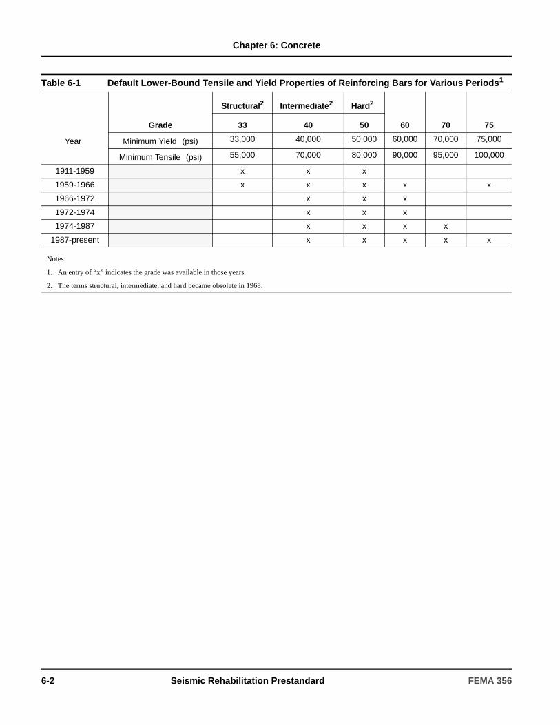
Chapter 6: Concrete
Table 6-1 Default Lower-Bound Tensile and Yield Properties of Reinforcing Bars for Various Periods1
Grade
Structural2 Intermediate21 Hard21
60 70 7533 40 50
Year3 Minimum Yield2 (psi) 33,000 40,000 50,000 60,000 70,000 75,000
Minimum Tensile2 (psi) 55,000 70,000 80,000 90,000 95,000 100,000
1911-1959 x x x
1959-1966 x x x x x
1966-1972 x x x
1972-1974 x x x
1974-1987 x x x x
1987-present x x x x x
Notes:
1. An entry of “x” indicates the grade was available in those years.
2. The terms structural, intermediate, and hard became obsolete in 1968.
6-2 Seismic Rehabilitation Prestandard FEMA 356
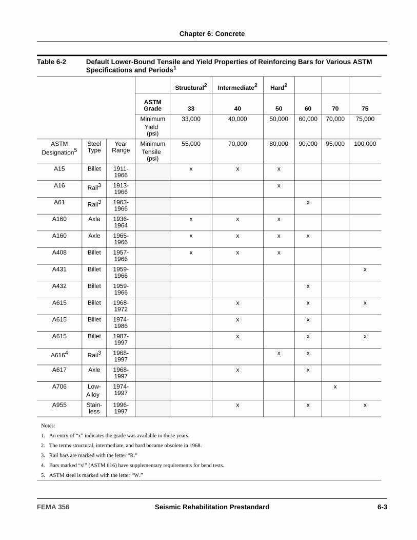
Chapter 6: Concrete
Table 6-2 Default Lower-Bound Tensile and Yield Properties of Reinforcing Bars for Various ASTM Specifications and Periods1
Structural2 Intermediate2 Hard2
ASTM Grade 33 40 50 60 70 75
Minimum Yield2
(psi)
33,000 40,000 50,000 60,000 70,000 75,000
ASTM Designation5
SteelType
YearRange
3
Minimum Tensile2
(psi)
55,000 70,000 80,000 90,000 95,000 100,000
A15 Billet 1911-1966
x x x
A16 Rail3 1913-1966
x
A61 Rail3 1963-1966
x
A160 Axle 1936-1964
x x x
A160 Axle 1965-1966
x x x x
A408 Billet 1957-1966
x x x
A431 Billet 1959-1966
x
A432 Billet 1959-1966
x
A615 Billet 1968-1972
x x x
A615 Billet 1974-1986
x x
A615 Billet 1987-1997
x x x
A6164 Rail3 1968-1997
x x
A617 Axle 1968-1997
x x
A706 Low-Alloy5
1974-1997
x
A955 Stain-less
1996-1997
x x x
Notes:
1. An entry of “x” indicates the grade was available in those years.
2. The terms structural, intermediate, and hard became obsolete in 1968.
3. Rail bars are marked with the letter “R.”
4. Bars marked “s!” (ASTM 616) have supplementary requirements for bend tests.
5. ASTM steel is marked with the letter “W.”
FEMA 356 Seismic Rehabilitation Prestandard 6-3

Chapter 6: Concrete
6.3 Material Properties and Condition Assessment
6.3.1 General
Mechanical properties for concrete materials and components shall be based on available construction documents and as-built conditions for the particular structure. Where such information fails to provide adequate information to quantify material properties or document the condition of the structure, such information shall be supplemented by materials tests and assessments of existing conditions as required in Section 2.2.6.
Material properties of existing concrete components shall be determined in accordance with Section 6.3.2. A condition assessment shall be conducted in accordance with Section 6.3.3. The extent of materials testing and condition assessment performed shall be used to determine the knowledge factor as specified in Section 6.3.4.
Use of default material properties shall be permitted in accordance with Section 6.3.2.5.
6.3.2 Properties of In-Place Materials and Components
6.3.2.1 Material Properties
6.3.2.1.1 General
The following component and connection material properties shall be obtained for the as-built structure:
1. Concrete compressive strength.
2. Yield and ultimate strength of conventional and prestressing reinforcing steel and metal connection hardware.
When materials testing is required by Section 2.2.6, the test methods to quantify material properties shall comply with the requirements of Section 6.3.2.3. The frequency of sampling, including the minimum number of tests for property determination shall comply with the requirements of Section 6.3.2.4.
Table 6-3 Default Lower-Bound Compressive Strength of Structural Concrete (psi)1
Time Frame Footings Beams Slabs Columns Walls
1900–1919 1000–2500 2000–3000 1500–3000 1500–3000 1000–2500
1920–1949 1500–3000 2000–3000 2000–3000 2000–4000 2000–3000
1950–1969 2500–3000 3000–4000 3000–4000 3000–6000 2500–4000
1970–Present 3000–4000 3000–5000 3000–5000 3000–100002 3000–5000
Table 6-4 Factors to Translate Lower Bound Material Properties to Expected Strength Material Properties
Material Property Factor
Concrete Compressive Strength 1.50
Reinforcing Steel Tensile & Yield Strength
1.25
Connector Steel Yield Strength 1.50
C6.3.1 General
This section identifies properties requiring consideration and provides guidelines for determining the properties of buildings. Also described is the need for a thorough condition assessment and utilization of knowledge gained in analyzing component and system behavior. Personnel involved in material property quantification and condition assessment shall be experienced in the proper implementation of testing practices and the interpretation of results.
Documentation of properties and grades of material used in component/connection construction is invaluable and may be effectively used to reduce the amount of in-place testing required. The design professional is encouraged to research and acquire all available records from original construction.
6-4 Seismic Rehabilitation Prestandard FEMA 356
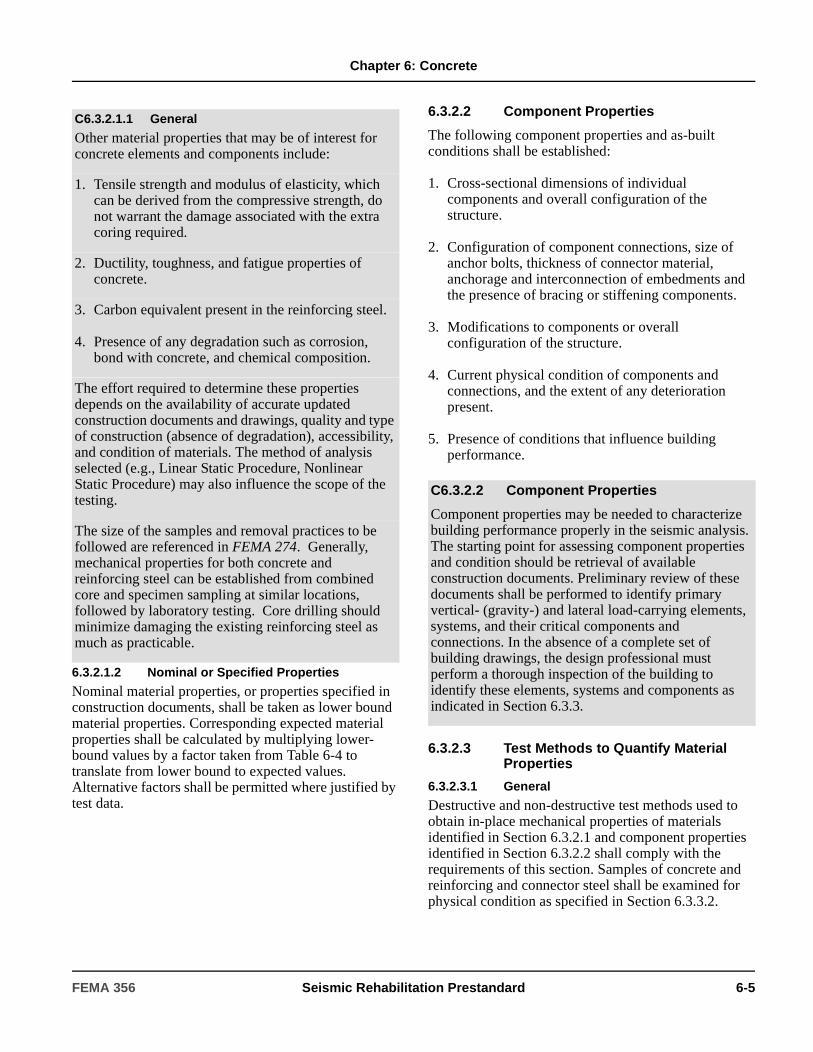
Chapter 6: Concrete
6.3.2.1.2 Nominal or Specified Properties
Nominal material properties, or properties specified in construction documents, shall be taken as lower bound material properties. Corresponding expected material properties shall be calculated by multiplying lower-bound values by a factor taken from Table 6-4 to translate from lower bound to expected values. Alternative factors shall be permitted where justified by test data.
6.3.2.2 Component Properties
The following component properties and as-built conditions shall be established:
1. Cross-sectional dimensions of individual components and overall configuration of the structure.
2. Configuration of component connections, size of anchor bolts, thickness of connector material, anchorage and interconnection of embedments and the presence of bracing or stiffening components.
3. Modifications to components or overall configuration of the structure.
4. Current physical condition of components and connections, and the extent of any deterioration present.
5. Presence of conditions that influence building performance.
6.3.2.3 Test Methods to Quantify Material Properties
6.3.2.3.1 General
Destructive and non-destructive test methods used to obtain in-place mechanical properties of materials identified in Section 6.3.2.1 and component properties identified in Section 6.3.2.2 shall comply with the requirements of this section. Samples of concrete and reinforcing and connector steel shall be examined for physical condition as specified in Section 6.3.3.2.
C6.3.2.1.1 General
Other material properties that may be of interest for concrete elements and components include:
1. Tensile strength and modulus of elasticity, which can be derived from the compressive strength, do not warrant the damage associated with the extra coring required.
2. Ductility, toughness, and fatigue properties of concrete.
3. Carbon equivalent present in the reinforcing steel.
4. Presence of any degradation such as corrosion, bond with concrete, and chemical composition.
The effort required to determine these properties depends on the availability of accurate updated construction documents and drawings, quality and type of construction (absence of degradation), accessibility, and condition of materials. The method of analysis selected (e.g., Linear Static Procedure, Nonlinear Static Procedure) may also influence the scope of the testing.
The size of the samples and removal practices to be followed are referenced in FEMA 274. Generally, mechanical properties for both concrete and reinforcing steel can be established from combined core and specimen sampling at similar locations, followed by laboratory testing. Core drilling should minimize damaging the existing reinforcing steel as much as practicable.
C6.3.2.2 Component Properties
Component properties may be needed to characterize building performance properly in the seismic analysis. The starting point for assessing component properties and condition should be retrieval of available construction documents. Preliminary review of these documents shall be performed to identify primary vertical- (gravity-) and lateral load-carrying elements, systems, and their critical components and connections. In the absence of a complete set of building drawings, the design professional must perform a thorough inspection of the building to identify these elements, systems and components as indicated in Section 6.3.3.
FEMA 356 Seismic Rehabilitation Prestandard 6-5

Chapter 6: Concrete
If the determination of material properties is accomplished through removal and testing of samples for laboratory analysis, sampling shall take place in primary gravity- and lateral-force-resisting components in regions with the least stress.
Expected material properties shall be based on mean test values. Lower bound material properties shall be based on mean test values minus one standard deviation.
6.3.2.3.2 Sampling
For concrete, the sampling program shall consist of the removal of standard cores. Core drilling shall be preceded by nondestructive location of the reinforcing steel. Core holes shall be filled with comparable-strength concrete or grout. If conventional reinforcing and bonded prestressing steel is tested, sampling shall consist of the removal of local bar segments and installation of replacement spliced material to maintain continuity of the rebar for transfer of bar force.
Core strength shall be converted to in situ concrete compressive strength (ƒc) by an approved procedure.
If a sample population greater than the minimum specified in Section 6.3.2.4 is used in the testing program and the coefficient of variation in test results is less than 14%, the mean strength derived shall be permitted to be used as the expected strength in the analysis. The expected concrete strength shall not exceed the mean less one standard deviation in situations where the coefficient of variation is greater than 14%.
Removal of core samples and performance of laboratory destructive testing shall be permitted as a method of determining existing concrete strength properties. Removal of core samples shall employ the procedures contained in ASTM C42/C42M-99. Testing shall follow the procedures contained in ASTM C42/C42M-99, ASTM C39/C39M-99, and ASTM C496-96. The measured strength from testing shall be correlated to in-place concrete compressive strength.
Removal of bar or tendon length samples and performance of laboratory destructive testing shall be permitted as a method of determining existing reinforcing steel strength properties. The tensile yield strength and ultimate strength for reinforcing and prestressing steels shall be obtained using the
procedures contained in ASTM A370-97a. Prestressing materials also shall meet the supplemental requirements in ASTM A416/A416M-99, ASTM A421/A421M-98a, or ASTM A722/A722M-98, depending on material type. Properties of connector steels shall be permitted to be determined by wet and dry chemical composition tests, and direct tensile and compressive strength tests as specified by ASTM A370-97a. Where strengths of embedded connectors are required, in situ testing shall satisfy the provisions of ASTM E488-96.
6.3.2.4 Minimum Number of Tests
Materials testing is not required if material properties are available from original construction documents that include material test records or material test reports.
The minimum number of tests necessary to quantify properties by in-place testing for comprehensive data collection shall be as specified in Sections 6.3.2.4.1 through 6.3.2.4.4. The minimum number of tests for usual data collection shall be as specified in Section 6.3.2.4.5. If the existing vertical or lateral-force-resisting system is being replaced in the rehabilitation process, material testing shall be required
C6.3.2.3 Test Methods to Quantify Material Properties
ACI 318 and FEMA 274 provide further guidance on correlating core strength to in-place strength and provides references for various test methods that may be used to estimate material properties.
The chemical composition may also be determined from the retrieved samples.
FEMA 274 provides references for these tests.
Usually, the reinforcing steel system used in the construction of a specific building is of a common grade and strength. Occasionally one grade of reinforcement is used for small-diameter bars (e.g., those used for stirrups and hoops) and another grade for large-diameter bars (e.g., those used for longitudinal reinforcement). Furthermore, it is possible that a number of different concrete design strengths (or “classes”) have been employed. Historical research and industry documents also contain insight on material mechanical properties used in different construction eras.
6-6 Seismic Rehabilitation Prestandard FEMA 356
Chapter 6: Concrete
only to qualify properties of existing materials at new connection points.
6.3.2.4.1 Comprehensive Testing
Unless specified otherwise, a minimum of three tests shall be conducted to determine any property. If the coefficient of variation exceeds 14%, additional tests shall be performed until the coefficient of variation is equal to or less than 14%.
6.3.2.4.2 Concrete Materials
For each concrete element type (such as a shear wall), a minimum of three core samples shall be taken and subjected to compression tests. A minimum of six total tests shall be performed on a building for concrete strength determination, subject to the limitations of this section. If varying concrete classes/grades were employed in the construction of the building, a minimum of three samples and tests shall be performed for each class. The modulus of elasticity shall be permitted to be estimated from the data of strength testing. Samples shall be taken from randomly selected components critical to structural behavior of the building. Tests also shall be performed on samples from components that are damaged or degraded, if such
damage or degradation is identified to quantify their condition. Test results shall be compared with strength values specified in the construction documents. If test values less than the specified strength in the construction documents are found, further strength testing shall be performed to determine the cause or identify the extent of the condition.
The minimum number of tests to determine compressive and tensile strength shall conform to the following criteria.
1. For concrete elements for which the specified design strength is known and test results are not available, a minimum of three cores/tests shall be conducted for each floor level, 400 cubic yards of concrete, or 10,000 square feet of surface area, whichever requires the most frequent testing.
2. For concrete elements for which the design strength is unknown and test results are not available, a minimum of six cores/tests shall be conducted for each floor level, 400 cubic yards of concrete, or 10,000 square feet of surface area, whichever requires the most frequent testing. Where the results indicate that different classes of concrete were employed, the degree of testing shall be increased to confirm class use.
Quantification of concrete strength via ultrasonics or other nondestructive test methods shall not be substituted for core sampling and laboratory testing.
6.3.2.4.3 Conventional Reinforcing and Connector Steels
The minimum number of tests required to determine reinforcing and connector steel strength properties shall be as follows. Connector steel shall be defined as additional structural steel or miscellaneous metal used to secure precast and other concrete shapes to the building structure. Tests shall determine both yield and ultimate strengths of reinforcing and connector steel. A minimum of three tensile tests shall be conducted on conventional reinforcing steel samples from a building
C6.3.2.4 Minimum Number of Tests
In order to quantify in-place properties accurately, it is important that a minimum number of tests be conducted on primary components in the lateral-force-resisting system. The minimum number of tests is dictated by available data from original construction, the type of structural system employed, desired accuracy, and the quality and condition of in-place materials. The accessibility of the structural system may also influence the testing program scope. The focus of this testing shall be on primary lateral-force-resisting components and on specific properties needed for analysis. The test quantities provided in this section are minimum numbers; the design professional should determine whether further testing is needed to evaluate as-built conditions.
Testing is generally not required on components other than those of the lateral-force-resisting system.
The design professional (and subcontracted testing agency) should carefully examine test results to verify that suitable sampling and testing procedures were followed and that appropriate values for the analysis were selected from the data.
C6.3.2.4.2 Concrete Materials
Ultrasonics and nondestructive test methods should not be substituted for core sampling and laboratory testing since they do not yield accurate strength values directly.
FEMA 356 Seismic Rehabilitation Prestandard 6-7
Chapter 6: Concrete
for strength determination, subject to the following supplemental conditions.
1. If original construction documents defining properties exist, at least three strength coupons shall be randomly removed from each element or component type and tested.
2. If original construction documents defining properties do not exist, but the approximate date of construction is known and a common material grade is confirmed, at least three strength coupons shall be randomly removed from each element or component type for every three floors of the building. If the date of construction is unknown, at least six such samples/tests, for every three floors, shall be performed.
All sampled steel shall be replaced with new fully spliced and connected material unless an analysis confirms that replacement of original components is not required.
6.3.2.4.4 Prestressing Steels
The sampling of prestressing steel tendons for laboratory testing shall be required only for those prestressed components that are a part of the lateral-force-resisting system. Prestressed components in diaphragms shall be permitted to be excluded from testing.
Tendon or prestress removal shall be avoided if possible by sampling of either the tendon grip or extension beyond the anchorage.
All sampled prestressed steel shall be replaced with new fully connected and stressed material and anchorage hardware unless an analysis confirms that replacement of original components is not required.
6.3.2.4.5 Usual Testing
The minimum number of tests to determine concrete and reinforcing steel material properties for usual data collection shall be based on the following criteria:
1. If the specified design strength of the concrete is known, at least one core shall be taken from samples of each different concrete strength used in the
construction of the building, with a minimum of three cores taken for the entire building.
2. If the specified design strength of the concrete is not known, at least one core shall be taken from each type of component, with a minimum of six cores taken for the entire building.
3. If the specified design strength of the reinforcing steel is known, use of nominal or specified material properties shall be permitted without additional testing.
4. If the specified design strength of the reinforcing steel is not known, at least two strength coupons of reinforcing steel shall be removed from a building for testing.
6.3.2.5 Default Properties
Use of default material properties to determine component strengths shall be permitted in conjunction with the linear analysis procedures of Chapter 3.
Default lower-bound concrete compressive strengths shall be taken from Table 6-3. Default expected strength concrete compressive strengths shall be determined by multiplying lower-bound values by an appropriate factor selected from Table 6-4 unless another factor is justified by test data. The appropriate default compressive strength—lower bound or expected strength as specified in Section 2.4.4—shall be used to establish other strength and performance characteristics for the concrete as needed in the structural analysis.
Default lower-bound values for reinforcing steel shall be taken from Table 6-1 or 6-2. Default expected strength values for reinforcing steel shall be determined by multiplying lower-bound values by an appropriate factor selected from Table 6-4 unless another factor is justified by test data. For Rehabilitation Objectives in which default values are assumed for existing reinforcing steel, welding or mechanical coupling of
C6.3.2.4.5 Usual Testing
For other material properties, such as hardness and ductility, no minimum number of tests is prescribed. Similarly, standard test procedures may not exist. The design professional should examine the particular need for this type of testing and establish an adequate protocol.
6-8 Seismic Rehabilitation Prestandard FEMA 356
Chapter 6: Concrete
new reinforcement to the existing reinforcing steel shall not be used.
The default lower-bound yield strength for steel connector material shall be taken as 27,000 psi. The default expected yield strength for steel connector material shall be determined by multiplying lower-bound values by an appropriate factor selected from Table 6-4 unless another value is justified by test data.
Default values for prestressing steel in prestressed concrete construction shall not be used.
6.3.3 Condition Assessment
6.3.3.1 General
A condition assessment of the existing building and site conditions shall be performed as specified in this section.
The condition assessment shall include the following:
1. The physical condition of primary and secondary components shall be examined and the presence of any degradation shall be noted.
2. The presence and configuration of components and their connections, and the continuity of load paths
between components, elements, and systems shall be verified or established.
3. Other conditions including neighboring party walls and buildings, presence of nonstructural components, prior remodeling, and limitations for rehabilitation that may influence building performance shall be reviewed and documented.
4. A basis for selecting a knowledge factor in accordance with Section 6.3.4 shall be formulated.
5. Component orientation, plumbness, and physical dimensions shall be confirmed.
6.3.3.2 Scope and Procedures
The scope of the condition assessment shall include all accessible structural elements and components involved in lateral load resistance.
6.3.3.2.1 Visual Condition Assessment
Direct visual inspection of accessible and representative primary components and connections shall be performed to identify any configurational issues, determine whether degradation is present, establish continuity of load paths, establish the need for other test methods to quantify the presence and degree of degradation, and measure dimensions of existing construction to compare with available design information and reveal any permanent deformations.
Visual inspection of the building shall include visible portions of foundations, lateral-force-resisting members, diaphragms (slabs), and connections. As a minimum, a representative sampling of at least 20% of the elements, components, and connections shall be visually inspected at each floor level. If significant damage or degradation is found, the assessment sample of all critical components of similar type in the building shall be increased to 40%.
If coverings or other obstructions exist, indirect visual inspection through the obstruction, using drilled holes and a fiberscope, shall be permitted.
C6.3.2.5 Default Properties
Default values provided in this standard are generally conservative. While strength of reinforcing steel may be fairly consistent throughout a building, the strength of concrete in a building could be highly variable, given variability in concrete mix designs and sensitivity to water-cement ratio and curing practices.
Until about 1920, a variety of proprietary reinforcing steels was used. Yield strengths are likely to be in the range of 33,000 to 55,000 psi, but higher values are possible and actual yield and tensile strengths may exceed minimum values. Once commonly used to designate reinforcing steel grade, the terms structural, intermediate and hard became obsolete in 1968. Plain and twisted square bars were sometimes used between 1900 and 1949.
Factors to convert default reinforcing steel strength to expected strength include consideration of material overstrength and strain hardening.
C6.3.3.2 Scope and Procedures
The degree to which the condition assessment is performed will affect the knowledge (κ) factor as specified in Section 6.3.4.
FEMA 356 Seismic Rehabilitation Prestandard 6-9

Chapter 6: Concrete
6.3.3.2.2 Comprehensive Condition Assessment
Exposure is defined as local minimized removal of cover concrete and other materials to allow inspection of reinforcing system details. All damaged concrete cover shall be replaced after inspection. The following criteria shall be used for assessing primary connections in the building for comprehensive data collection:
1. If detailed design drawings exist, exposure of at least three different primary connections shall occur, with the connection sample including different types of connections. If no deviations from the drawings exist, it shall be permitted to consider the sample as being representative of installed conditions. If deviations are noted, then at least 25% of the specific connection type shall be inspected to identify the extent of deviation.
2. In the absence of detailed design drawings, at least three connections of each primary connection type shall be exposed for inspection. If common detailing among the three connections is observed, it shall be permitted to consider this condition as representative of installed conditions. If variations are observed among like connections, additional connections shall be inspected until an accurate understanding of building construction is gained.
6.3.3.2.3 Additional Testing
If additional destructive and nondestructive testing is required to determine the degree of damage or presence of deterioration or to understand the internal condition and quality of concrete, approved test methods shall be used.
6.3.3.3 Basis for the Mathematical Building Model
The results of the condition assessment shall be used to quantify the following items needed to create the mathematical building model:
1. Component section properties and dimensions.
2. Component configuration and the presence of any eccentricities or permanent deformation.
3. Connection configuration and the presence of any eccentricities.
C6.3.3.2.3 Additional Testing
The physical condition of components and connectors will affect their performance. The need to accurately identify the physical condition may also dictate the need for certain additional destructive and nondestructive test methods. Such methods may be used to determine the degree of damage or presence of deterioration, and to improve understanding of the internal condition and quality of the concrete. Further guidelines and procedures for destructive and nondestructive tests that may be used in the condition assessment are provided in FEMA 274 and FEMA 306. The following paragraphs identify those nondestructive examination (NDE) methods having the greatest use and applicability to condition assessment.
• Surface NDE methods include infrared thermography, delamination sounding, surface hardness measurement, and crack mapping. These methods may be used to find surface degradation in components such as service-induced cracks, corrosion, and construction defects.
• Volumetric NDE methods, including radiography and ultrasonics, may be used to identify the presence of internal discontinuities, as well as to identify loss of section. Impact-echo ultrasonics is particularly useful because of ease of implementation and proven capability in concrete.
• Structural condition and performance may be assessed through on-line monitoring using acoustic emissions and strain gauges, and in-place static or dynamic load tests. Monitoring is used to determine if active degradation or deformations are occurring, while nondestructive load testing provides direct insight on load-carrying capacity.
• Locating, sizing, and initial assessment of the reinforcing steel may be completed using electromagnetic methods (such as a pacometer) or radiography. Further assessment of suspected corrosion activity should use electrical half-cell potential and resistivity measurements.
• Where it is absolutely essential, the level of prestress remaining in an unbonded prestressed system may be measured using lift-off testing (assuming original design and installation data are available), or another nondestructive method such as “coring stress relief” specified in ASCE 11.
6-10 Seismic Rehabilitation Prestandard FEMA 356

Chapter 6: Concrete
4. Presence and effect of alterations to the structural system since original construction.
5. Interaction of nonstructural components and their involvement in lateral load resistance.
All deviations between available construction records and as-built conditions obtained from visual inspection shall be accounted for in the structural analysis.
Unless concrete cracking, reinforcing corrosion, or other mechanisms are observed in the condition assessment to be causing damage or reduced capacity, the cross-sectional area and other sectional properties shall be taken as those from the design drawings. If some sectional material loss has occurred, the loss shall be quantified by direct measurement and sectional properties shall be reduced accordingly, using principles of structural mechanics.
6.3.4 Knowledge Factor
A knowledge factor (κ) for computation of concrete component capacities and permissible deformations shall be selected in accordance with Section 2.2.6.4 with the following additional requirements specific to concrete components.
A knowledge factor, κ, equal to 0.75 shall be used if any of the following criteria are met:
1. Components are found damaged or deteriorated during assessment, and further testing is not performed to quantify their condition or justify the use of κ=1.0.
2. Component mechanical properties have a coefficient of variation exceeding 25%.
3. Components contain archaic or proprietary material and the condition is uncertain.
6.4 General Assumptions and Requirements
6.4.1 Modeling and Design
6.4.1.1 General Approach
Seismic rehabilitation of concrete structural elements of existing buildings shall comply with the requirements of ACI 318, except as otherwise indicated in this standard. Seismic evaluation shall identify brittle or low-ductility failure modes of force-controlled actions as defined in Section 2.4.4.
Evaluation of demands and capacities of reinforced concrete components shall include consideration of locations along the length where lateral and gravity loads produce maximum effects, where changes in cross-section or reinforcement result in reduced strength, and where abrupt changes in cross section or reinforcement, including splices, may produce stress concentrations, resulting in premature failure.
6.4.1.2 Stiffness
Component stiffnesses shall be calculated considering shear, flexure, axial behavior and reinforcement slip deformations. Consideration shall be given to the state of stress on the component due to volumetric changes from temperature and shrinkage, and to deformation levels to which the component will be subjected under gravity and earthquake loading.
6.4.1.2.1 Linear Procedures
Where design actions are determined using the linear procedures of Chapter 3, component effective stiffnesses shall correspond to the secant value to the yield point of the component. The use of higher stiffnesses shall be permitted where it is demonstrated by analysis to be appropriate for the design loading.
C6.4.1.1 General Approach
Brittle or low-ductility failure modes typically include behavior in direct or nearly-direct compression, shear in slender components and in component connections, torsion in slender components, and reinforcement development, splicing, and anchorage. It is recommended that the stresses, forces, and moments acting to cause these failure modes be determined from a limit-state analysis considering probable resistances at locations of nonlinear action.
FEMA 356 Seismic Rehabilitation Prestandard 6-11
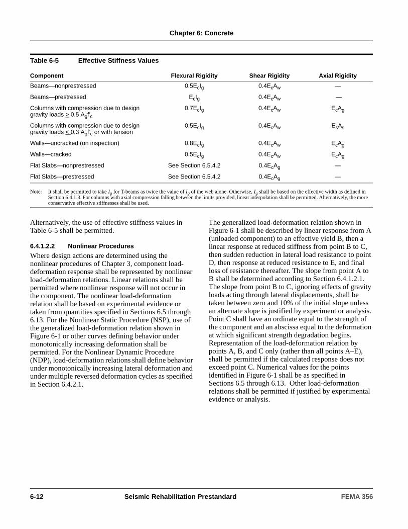
Chapter 6: Concrete
Alternatively, the use of effective stiffness values in Table 6-5 shall be permitted.
6.4.1.2.2 Nonlinear Procedures
Where design actions are determined using the nonlinear procedures of Chapter 3, component load-deformation response shall be represented by nonlinear load-deformation relations. Linear relations shall be permitted where nonlinear response will not occur in the component. The nonlinear load-deformation relation shall be based on experimental evidence or taken from quantities specified in Sections 6.5 through 6.13. For the Nonlinear Static Procedure (NSP), use of the generalized load-deformation relation shown in Figure 6-1 or other curves defining behavior under monotonically increasing deformation shall be permitted. For the Nonlinear Dynamic Procedure (NDP), load-deformation relations shall define behavior under monotonically increasing lateral deformation and under multiple reversed deformation cycles as specified in Section 6.4.2.1.
The generalized load-deformation relation shown in Figure 6-1 shall be described by linear response from A (unloaded component) to an effective yield B, then a linear response at reduced stiffness from point B to C, then sudden reduction in lateral load resistance to point D, then response at reduced resistance to E, and final loss of resistance thereafter. The slope from point A to B shall be determined according to Section 6.4.1.2.1. The slope from point B to C, ignoring effects of gravity loads acting through lateral displacements, shall be taken between zero and 10% of the initial slope unless an alternate slope is justified by experiment or analysis. Point C shall have an ordinate equal to the strength of the component and an abscissa equal to the deformation at which significant strength degradation begins. Representation of the load-deformation relation by points A, B, and C only (rather than all points A–E), shall be permitted if the calculated response does not exceed point C. Numerical values for the points identified in Figure 6-1 shall be as specified in Sections 6.5 through 6.13. Other load-deformation relations shall be permitted if justified by experimental evidence or analysis.
Table 6-5 Effective Stiffness Values
Component Flexural Rigidity Shear Rigidity Axial Rigidity
Beams—nonprestressed 0.5EcIg 0.4EcAw —
Beams—prestressed EcIg 0.4EcAw —
Columns with compression due to design gravity loads > 0.5 Agf’c
0.7EcIg 0.4EcAw EcAg
Columns with compression due to design gravity loads < 0.3 Agf’c or with tension
0.5EcIg 0.4EcAw EsAs
Walls—uncracked (on inspection) 0.8EcIg 0.4EcAw EcAg
Walls—cracked 0.5EcIg 0.4EcAw EcAg
Flat Slabs—nonprestressed See Section 6.5.4.2 0.4EcAg —
Flat Slabs—prestressed See Section 6.5.4.2 0.4EcAg —
Note: It shall be permitted to take Ig for T-beams as twice the value of Ig of the web alone. Otherwise, Ig shall be based on the effective width as defined in Section 6.4.1.3. For columns with axial compression falling between the limits provided, linear interpolation shall be permitted. Alternatively, the more conservative effective stiffnesses shall be used.
6-12 Seismic Rehabilitation Prestandard FEMA 356

Chapter 6: Concrete
C6.4.1.2.2 Nonlinear Procedures
Typically, the responses shown in Figure 6-1 are associated with flexural response or tension response. In this case, the resistance at Q/Qy = 1.0 is the yield value, and subsequent strain hardening accommodates strain hardening in the load-deformation relation as the member is deformed toward the expected strength. When the response shown in Figure 6-1 is associated with compression, the resistance at Q/Qy = 1.0 typically is the value at which concrete begins to spall, and strain hardening in well-confined sections may be associated with strain hardening of the longitudinal reinforcement and the confined concrete. When the response shown in Figure 6-1 is associated with shear, the resistance at Q/Qy = 1.0 typically is the value at which the design shear strength is reached, and no strain hardening follows.
The deformations used for the load-deformation relation of Figure 6-1 shall be defined in one of two ways, as follows:
(a) Deformation, or Type I. In this curve, deformations are expressed directly using terms such as strain, curvature, rotation, or elongation. The parameters a and b shall refer to those portions of the deformation that occur after yield; that is, the plastic deformation. The parameter c is the reduced resistance after the sudden reduction from C to D. Parameters a, b, and c are defined numerically in various tables in this chapter. Alternatively, it shall be permitted to determine the parameters a, b, and c directly by analytical procedures justified by experimental evidence.
(b) Deformation Ratio, or Type II. In this curve, deformations are expressed in terms such as shear angle and tangential drift ratio. The parameters d and e refer to total deformations measured from the origin. Parameters c, d, and e are defined numerically in various tables in this chapter. Alternatively, it shall be permitted to determine the parameters c, d, and e directly by analytical procedures justified by experimental evidence.
Figure 6-1 Generalized Force-Deformation Relations for Concrete Elements or Components
FEMA 356 Seismic Rehabilitation Prestandard 6-13
Chapter 6: Concrete
6.4.1.3 Flanged Construction
In beams consisting of a web and flange that act integrally, the combined stiffness and strength for flexural and axial loading shall be calculated considering a width of effective flange on each side of the web equal to the smaller of: (1) the provided flange width, (2) eight times the flange thickness, (3) half the distance to the next web, or (4) one-fifth of the span for beams. When the flange is in compression, both the concrete and reinforcement within the effective width shall be considered effective in resisting flexure and axial load. When the flange is in tension, longitudinal reinforcement within the effective width and that is developed beyond the critical section shall be considered fully effective for resisting flexural and axial loads. The portion of the flange extending beyond the width of the web shall be assumed ineffective in resisting shear.
In walls, effective flange width shall be in accordance with Chapter 21 of ACI 318.
6.4.2 Strength and Deformability
6.4.2.1 General
Actions in a structure shall be classified as being either deformation-controlled or force-controlled, as defined in Section 2.4.4. Design strengths for deformation-controlled and force-controlled actions shall be calculated in accordance with Sections 6.4.2.2 and 6.4.2.3, respectively.
Components shall be classified as having low, moderate, or high ductility demands according to Section 6.4.2.4.
Where strength and deformation capacities are derived from test data, the tests shall be representative of proportions, details, and stress levels for the component and comply with requirements specified in Section 2.8.1.
The strength and deformation capacities of concrete members shall correspond to values resulting from earthquake loadings involving three fully reversed cycles to the design deformation level unless a larger or smaller number of deformation cycles is determined considering earthquake duration and the dynamic properties of the structure.
6.4.2.2 Deformation-Controlled Actions
Strengths used for deformation-controlled actions shall be taken as equal to expected strengths, QCE, obtained experimentally, or calculated using accepted principles of mechanics. Expected strength is defined as the mean maximum resistance expected over the range of deformations to which the concrete component is likely to be subjected. When calculations are used to define expected strength, expected material properties shall be used. Unless other procedures are specified in this standard, procedures specified in ACI 318 to calculate design strengths shall be permitted except that the strength reduction factor, φ, shall be taken equal to unity. Deformation capacities for acceptance of deformation-controlled actions calculated by nonlinear procedures shall be as specified in Sections 6.5 to Section 6.13. For components constructed of lightweight concrete, QCE shall be modified in accordance with ACI 318 procedures for lightweight concrete.
C6.4.2.1 General
Strengths and deformation capacities given in this chapter are for earthquake loadings involving three fully reversed deformation cycles to the design deformation levels, in addition to similar cycles to lesser deformation levels. In some cases—including some short-period buildings and buildings subjected to a long-duration design earthquake—a building may be expected to be subjected to additional cycles to the design deformation levels. The increased number of cycles may lead to reductions in resistance and deformation capacity. The effects on strength and deformation capacity of additional deformation cycles should be considered in design. Large earthquakes will cause additional cycles.
C6.4.2.2 Deformation-Controlled Actions
Expected yield strength of reinforcing steel, as specified in this standard, includes consideration of material overstrength and strain hardening.
6-14 Seismic Rehabilitation Prestandard FEMA 356

Chapter 6: Concrete
6.4.2.3 Force-Controlled Actions
Strengths used for force-controlled actions shall be taken as lower-bound strengths, QCL, obtained experimentally, or calculated using established principles of mechanics. Lower-bound strength is defined as the mean minus one standard deviation of resistance expected over the range of deformations and loading cycles to which the concrete component is likely to be subjected. When calculations are used to define lower-bound strengths, lower bound estimates of material properties shall be used. Unless other procedures are specified in this standard, procedures specified in ACI 318 to calculate design strengths shall be permitted, except that the strength reduction factor, φ, shall be taken equal to unity. For components constructed of lightweight concrete, QCL shall be modified in accordance with ACI 318 procedures for lightweight concrete.
6.4.2.4 Component Ductility Demand Classification
Where procedures in this chapter require classification of component ductility demand, components shall be classified as having low, moderate, or high ductility demands, based on the maximum value of the demand capacity ratio (DCR) defined in Section 2.4.1 for linear procedures, or the calculated displacement ductility for nonlinear procedures in accordance with Table 6-6.
6.4.3 Flexure and Axial Loads
Flexural strength and deformation capacity of members with and without axial loads shall be calculated according to the procedures of ACI 318 or by other approved methods. Strengths and deformation capacities of components with monolithic flanges shall be calculated considering concrete and developed longitudinal reinforcement within the effective flange width as defined in Section 6.4.1.3.
Strength and deformation capacities shall be determined considering available development of longitudinal reinforcement. Where longitudinal reinforcement has embedment or development length that is insufficient for development of reinforcement strength, flexural strength shall be calculated based on limiting stress capacity of the embedded bar as defined in Section 6.4.5.
Where flexural deformation capacities are calculated from basic principles of mechanics, reductions in deformation capacity due to applied shear shall be taken into consideration. When using analytical models for flexural deformability that do not directly consider effect of shear, and where design shear equals or
exceeds Aw, where f ′c is in psi and Aw is gross
area of web in square inches, the design value shall not exceed eighty percent of the value calculated using the analytical model.
For concrete columns under combined axial load and biaxial bending, the combined strength shall be evaluated considering biaxial bending. When using linear procedures, the design axial load, PUF, shall be calculated as a force-controlled action in accordance with Section 3.4. The design moments, MUD, shall be calculated about each principal axis in accordance with Section 3.4. Acceptance shall be based on the following equation:
(6-1)
Table 6-6 Component Ductility Demand Classification
Maximum value of DCR or displacement ductility Descriptor
< 2 Low Ductility Demand
2 to 4 Moderate Ductility Demand
> 4 High Ductility Demand
6 fc′
MUDx
mxκMCEx-------------------------
2 MUDy
myκMCEy-------------------------
+2
1≤
FEMA 356 Seismic Rehabilitation Prestandard 6-15

Chapter 6: Concrete
where:
Alternative approaches based on principles of mechanics shall be permitted.
6.4.3.1 Usable Strain Limits
Without confining transverse reinforcement, the maximum usable strain at the extreme concrete compression fiber shall not exceed 0.002 for components in nearly pure compression and 0.005 for other components unless larger strains are substantiated by experimental evidence and approved. Maximum usable compressive strains for confined concrete shall be based on experimental evidence and shall consider limitations posed by fracture of transverse reinforcement, buckling of longitudinal reinforcement, and degradation of component resistance at large
deformation levels. Maximum compressive strains in longitudinal reinforcement shall not exceed 0.02, and maximum tensile strains in longitudinal reinforcement shall not exceed 0.05.
6.4.4 Shear and Torsion
Strengths in shear and torsion shall be calculated according to ACI 318 except as modified in this standard.
Within yielding regions of components with moderate or high ductility demands, shear and torsional strength shall be calculated according to procedures for ductile components, such as the provisions in Chapter 21 of ACI 318. Within yielding regions of components with low ductility demands and outside yielding regions for all ductility demands, calculation of design shear strength using procedures for effective elastic response such as the provisions in Chapter 11 of ACI 318 shall be permitted.
Where the longitudinal spacing of transverse reinforcement exceeds half the component effective depth measured in the direction of shear, transverse reinforcement shall be assumed not more than 50% effective in resisting shear or torsion. Where the longitudinal spacing of transverse reinforcement exceeds the component effective depth measured in the direction of shear, transverse reinforcement shall be assumed ineffective in resisting shear or torsion. For beams and columns in which perimeter hoops are either lap-spliced or have hooks that are not adequately anchored in the concrete core, transverse reinforcement shall be assumed not more than 50% effective in regions of moderate ductility demand and shall be assumed ineffective in regions of high ductility demand.
Shear friction strength shall be calculated according to ACI 318, taking into consideration the expected axial load due to gravity and earthquake effects. Where rehabilitation involves the addition of concrete requiring overhead work with dry-pack, the shear friction coefficient µ shall be taken as equal to 70% of the value specified by ACI 318.
MUDx = design bending moment about x axis for axial load PUF, kip-in.
MUDy = design bending moment about y axis for axial load PUF, kip-in.
MCEx = expected bending moment strength about x axis, kip-in.
MCEy = expected bending moment strength about y axis, kip-in.
mx = m-factor for column for bending about x axis
my = m-factor for column for bending about y axis
C6.4.3 Flexure and Axial Loads
Laboratory tests indicate that flexural deformability may be reduced as co-existing shear forces increase. As flexural ductility demands increase, shear capacity decreases, which may result in a shear failure before theoretical flexural deformation capacities are reached. Caution should be exercised when flexural deformation capacities are determined by calculation. FEMA 306 is a resource for guidance regarding the interaction between shear and flexure.
6-16 Seismic Rehabilitation Prestandard FEMA 356
Chapter 6: Concrete
6.4.5 Development and Splices of Reinforcement
Development of straight bars, hooked bars, and lap-spliced bars shall be calculated according to the provisions of ACI 318, with the following modifications:
1. Within yielding regions of components with moderate or high ductility demands as classified in Section 6.4.2.4, deformed straight bars, hooked bars, and lap-spliced bars shall meet the development requirements of Chapter 21 of ACI 318. Within yielding regions of components with low ductility demands, and outside yielding regions for all ductility demands, bars shall meet the development requirements of Chapter 12 of ACI 318, except requirements for lap splices shall be the same as those for straight development of bars in tension without consideration of lap splice classifications.
2. Where existing deformed straight bars, hooked bars, and lap-spliced bars do not meet the development requirements of (1) above, the capacity of existing reinforcement shall be calculated using Equation (6-2):
(6-2)
where fs = maximum stress that can be developed in the bar for the straight development, hook, or lap splice length lb provided; fy = yield strength of reinforcement; and ld = length required by Chapter 12 or Chapter 21 (as appropriate) of ACI 318 for straight development, hook development, or lap splice length, except required splice lengths may be taken as straight bar development lengths in tension. Where transverse reinforcement is distributed along the development length with spacing not exceeding one-third of the effective depth of the component, it shall be permitted to assume the reinforcement retains the calculated maximum stress to high ductility demands. For larger spacings of transverse reinforcement, the developed stress shall be assumed to degrade from fs to 0.2fs at a ductility demand or DCR equal to 2.0.
3. Strength of deformed straight, discontinuous bars embedded in concrete sections or beam-column joints, with clear cover over the embedded bar not less than 3db, shall be calculated according to Equation (6-3):
(6-3)
where fs = maximum stress (in psi) that can be developed in an embedded bar having embedment length le (in inches), db = diameter of embedded bar (in inches), and fy = bar yield stress (in psi). When fs is less than fy, and the calculated stress in the bar due to design loads equals or exceeds fs, the maximum developed stress shall be assumed to degrade from fs to 0.2fs at a ductility demand or DCR equal to 2.0. In beams with short bottom bar embedments into beam-column joints, flexural strength shall be calculated considering the stress limitation of Equation (6-3).
4. For plain straight bars, hooked bars, and lap-spliced bars, development and splice lengths shall be taken as twice the values determined in accordance with ACI 318 unless other lengths are justified by approved tests or calculations considering only the chemical bond between the bar and the concrete.
5. Doweled bars added in seismic rehabilitation shall be assumed to develop yield stress when all the following conditions are satisfied:
5.1. Drilled holes for dowel bars are cleaned with a stiff brush that extends the length of the hole.
5.2. Embedment length le is not less than 10db
5.3. Minimum spacing of dowel bars is not less than 4le and minimum edge distance is not less than 2le. Design values for dowel bars not satisfying these conditions shall be verified by test data. Field samples shall be obtained to ensure design strengths are developed in accordance with Section 6.4.6.3.
fslbld----fy=
fs2500
db------------le fy≤=
FEMA 356 Seismic Rehabilitation Prestandard 6-17

Chapter 6: Concrete
6.4.5.1 Square Reinforcing Bars
Square reinforcing bars in a building shall be classified as either twisted or straight. The developed strength of twisted square bars shall be as specified for deformed bars in Section 6.4.5, using an effective diameter calculated based on the gross area of the square bar. Straight square bars shall be considered as plain bars, and the developed strength shall be as specified for plain bars in Section 6.4.5.
6.4.6 Connections to Existing Concrete
Connections used to connect two or more components shall be classified according to their anchoring systems as cast-in-place or as post-installed.
6.4.6.1 Cast-In-Place Systems
Component actions on cast-in-place connection systems, including shear forces, tension forces, bending moments, and prying actions, shall be considered force-controlled. Lower-bound strength of connections shall be ultimate values as specified in an approved building code with .
The capacity of anchors placed in areas where cracking is expected shall be reduced by a factor of 0.5.
6.4.6.2 Post-Installed Systems
Component actions on post-installed connection systems shall be considered force-controlled. The lower-bound capacity of post-installed anchors shall be mean minus one standard deviation of ultimate values published in approved test reports.
6.4.6.3 Quality Assurance
Connections between existing concrete components and new components added to rehabilitate the structure shall be subject to the quality assurance provisions specified in Section 2.7. The design professional shall specify the required inspection and testing of cast-in-place and post-installed anchors as part of the Quality Assurance Plan.
6.4.7 Rehabilitation—General Requirements
Upon determining that concrete elements in an existing building are deficient for the selected Rehabilitation Objective, these elements shall be rehabilitated or replaced or the structure shall be otherwise rehabilitated so that the element is no longer deficient for the selected rehabilitation objective. If replacement of the element is selected, the new element shall be designed in accordance with an approved building code.
Rehabilitation measures shall be evaluated in accordance with the principles and requirements of this standard, to assure that the completed rehabilitation achieves the selected Rehabilitation Objective. The effects of rehabilitation on stiffness, strength, and deformability shall be taken into account in an analytical model of the rehabilitated structure. The compatibility of new and existing components shall be checked at displacements consistent with the selected performance level.
Connections required between existing and new elements shall satisfy the requirements of Section 6.4.6 and other requirements of this standard.
C6.4.5 Development and Splices of Reinforcement
Chapter 21 requirements for development of reinforcement in ACI 318 are intended for use in yielding components of reinforced concrete moment frame elements, and not shear wall components. When checking development of bars in shear wall components, Chapter 12 requirements should be used.
For buildings constructed prior to 1950, the bond strength developed between reinforcing steel and concrete may be less than present-day strength. Current equations for development and splices of reinforcement account for mechanical bond due to deformations present in deformed bars in addition to chemical bond. The length required to develop plain bars will be much greater than that required for deformed bars, and will be more sensitive to cracking in the concrete. Procedures for testing and assessment of tensile lap splices and development length of plain reinforcing steel may be found in CRSI.
φ 1.0=
6-18 Seismic Rehabilitation Prestandard FEMA 356
Chapter 6: Concrete
6.5 Concrete Moment Frames
6.5.1 Types of Concrete Moment Frames
Concrete moment frames shall be defined as elements composed primarily of horizontal framing components (beams and/or slabs), vertical framing components (columns) and joints connecting horizontal and vertical framing components. These elements resist lateral loads acting alone, or in conjunction with shear walls, braced frames, or other elements in a dual system.
Frames that are cast monolithically, including monolithic concrete frames created by the addition of new material, shall meet the provisions of this section. Frames covered under this section include reinforced concrete beam-column moment frames, prestressed concrete beam-column moment frames, and slab-column moment frames. Precast concrete frames, concrete frames with infills, and concrete braced frames shall meet the provisions of Sections 6.6, 6.7, and 6.10, respectively.
6.5.1.1 Reinforced Concrete Beam-Column Moment Frames
Reinforced concrete beam-column moment frames shall satisfy the following conditions:
1. Framing components shall be beams (with or without slabs), columns, and their connections.
2. Beams and columns shall be of monolithic construction that provides for moment transfer between beams and columns.
3. Primary reinforcement in components contributing to lateral load resistance shall be nonprestressed.
Special Moment Frames, Intermediate Moment Frames, and Ordinary Moment Frames as defined in ASCE 7, shall be deemed to satisfy the above conditions. This classification shall include existing construction, new construction, and existing construction that has been rehabilitated.
6.5.1.2 Post-Tensioned Concrete Beam- Column Moment Frames
Post-tensioned concrete beam-column moment frames shall satisfy the following conditions:
1. Framing components shall be beams (with or without slabs), columns, and their connections.
2. Frames shall be of monolithic construction that provides for moment transfer between beams and columns.
3. Primary reinforcement in beams contributing to lateral load resistance shall include post-tensioned reinforcement with or without mild reinforcement.
This classification shall include existing construction, new construction, and existing construction that has been rehabilitated.
6.5.1.3 Slab-Column Moment Frames
Slab-column moment frames shall satisfy the following conditions:
1. Framing components shall be slabs (with or without beams in the transverse direction), columns, and their connections.
2. Frames shall be of monolithic construction that provides for moment transfer between slabs and columns.
3. Primary reinforcement in slabs contributing to lateral load resistance shall include nonprestressed reinforcement, prestressed reinforcement, or both.
This classification shall include frames intended as part of the lateral-force-resisting system and frames not intended as part of the lateral-force-resisting system in the original design, including existing construction, new construction, and existing construction that has been rehabilitated.
FEMA 356 Seismic Rehabilitation Prestandard 6-19
Chapter 6: Concrete
6.5.2 Reinforced Concrete Beam-Column Moment Frames
6.5.2.1 General Considerations
The analytical model for a beam-column frame element shall represent strength, stiffness, and deformation capacity of beams, columns, beam-column joints, and other components of the frame, including connections with other elements. Potential failure in flexure, shear, and reinforcement development at any section along the component length shall be considered. Interaction with other elements, including nonstructural elements and components, shall be included.
Analytical models representing a beam- column frame using line elements with properties concentrated at component centerlines shall be permitted. Where beam and column centerlines do not intersect, the effects of the eccentricity between centerlines on framing shall be taken into account. Where the centerline of the narrower component falls within the middle third of the adjacent framing component measured transverse to the framing direction, however, this eccentricity need not be considered. Where larger eccentricities occur, the effect shall be represented either by reductions in effective stiffness, strength, and deformation capacity, or by direct modeling of the eccentricity.
The beam-column joint in monolithic construction shall be represented as a stiff or rigid zone having horizontal dimensions equal to the column cross-sectional dimensions and vertical dimension equal to the beam depth, except that a wider joint shall be permitted where the beam is wider than the column and where justified by experimental evidence. The model of the connection between the columns and foundation shall be selected based on the details of the column-foundation connection and rigidity of the foundation-soil system.
Action of the slab as a diaphragm interconnecting vertical elements shall be represented. Action of the slab as a composite beam flange shall be considered in developing stiffness, strength, and deformation capacities of the beam component model, according to Section 6.4.1.3.
Inelastic action shall be restricted to those components and actions listed in Tables 6-7 through 6-9, except where it is demonstrated by experimental evidence and analysis that other inelastic action is acceptable for the selected performance level. Acceptance criteria shall be as specified in Section 6.5.2.4.
6.5.2.2 Stiffness for Analysis
6.5.2.2.1 Linear Static and Dynamic Procedures
Beams shall be modeled considering flexural and shear stiffnesses, including the effect of the slab acting as a flange in monolithic construction. Columns shall be modeled considering flexural, shear, and axial stiffnesses. Joints shall be modeled as either stiff or rigid components. Effective stiffnesses shall be according to Section 6.4.1.2.
6.5.2.2.2 Nonlinear Static Procedure
Nonlinear load-deformation relations shall follow the requirements of Section 6.4.1.2.
Beams and columns shall be modeled using concentrated plastic hinge models or distributed plastic hinge models. Other models whose behavior has been demonstrated to represent the behavior of reinforced concrete beam and column components subjected to lateral loading shall be permitted. The beam and column model shall be capable of representing inelastic response along the component length, except where it is shown by equilibrium that yielding is restricted to the component ends. Where nonlinear response is expected in a mode other than flexure, the model shall be established to represent these effects.
Monotonic load-deformation relations shall be according to the generalized load-deformation relation shown in Figure 6-1, except that different relations shall be permitted where verified by experiments. The overall load-deformation relation shall be established so that the maximum resistance is consistent with the design strength specifications of Sections 6.4.2 and 6.5.2.3.
For beams and columns, the generalized deformation in Figure 6-1 shall be either the chord rotation or the plastic hinge rotation. For beam-column joints, the generalized deformation shall be shear strain. Values of the generalized deformation at points B, C, and D shall be derived from experiments or rational analyses, and shall take into account the interactions between flexure, axial load, and shear.
6-20 Seismic Rehabilitation Prestandard FEMA 356

Chapter 6: Concrete
Table 6-7 Modeling Parameters and Numerical Acceptance Criteria for Nonlinear Procedures—Reinforced Concrete Beams
Conditions
Modeling Parameters3 Acceptance Criteria3
Plastic Rotation Angle, radians
Residual Strength
Ratio
Plastic Rotation Angle, radians
Performance Level
IO
Component Type
Primary Secondary
a b c LS CP LS CP
i. Beams controlled by flexure1
Trans. Reinf.2
≤ 0.0 C ≤ 3 0.025 0.05 0.2 0.010 0.02 0.025 0.02 0.05
≤ 0.0 C ≥ 6 0.02 0.04 0.2 0.005 0.01 0.02 0.02 0.04
≥ 0.5 C ≤ 3 0.02 0.03 0.2 0.005 0.01 0.02 0.02 0.03
≥ 0.5 C ≥ 6 0.015 0.02 0.2 0.005 0.005 0.015 0.015 0.02
≤ 0.0 NC ≤ 3 0.02 0.03 0.2 0.005 0.01 0.02 0.02 0.03
≤ 0.0 NC ≥ 6 0.01 0.015 0.2 0.0015 0.005 0.01 0.01 0.015
≥ 0.5 NC ≤ 3 0.01 0.015 0.2 0.005 0.01 0.01 0.01 0.015
≥ 0.5 NC ≥ 6 0.005 0.01 0.2 0.0015 0.005 0.005 0.005 0.01
ii. Beams controlled by shear1
Stirrup spacing ≤ d/2 0.0030 0.02 0.2 0.0015 0.0020 0.0030 0.01 0.02
Stirrup spacing > d/2 0.0030 0.01 0.2 0.0015 0.0020 0.0030 0.005 0.01
iii. Beams controlled by inadequate development or splicing along the span1
Stirrup spacing ≤ d/2 0.0030 0.02 0.0 0.0015 0.0020 0.0030 0.01 0.02
Stirrup spacing > d/2 0.0030 0.01 0.0 0.0015 0.0020 0.0030 0.005 0.01
iv. Beams controlled by inadequate embedment into beam-column joint1
0.015 0.03 0.2 0.01 0.01 0.015 0.02 0.03
1. When more than one of the conditions i, ii, iii, and iv occurs for a given component, use the minimum appropriate numerical value from the table.
2. “C” and “NC” are abbreviations for conforming and nonconforming transverse reinforcement. A component is conforming if, within the flexural plastic hinge region, hoops are spaced at ≤ d/3, and if, for components of moderate and high ductility demand, the strength provided by the hoops (Vs) is at least three-fourths of the design shear. Otherwise, the component is considered nonconforming.
3. Linear interpolation between values listed in the table shall be permitted.
ρ ρ′–ρbal
-------------- V
bwd fc′--------------------
FEMA 356 Seismic Rehabilitation Prestandard 6-21
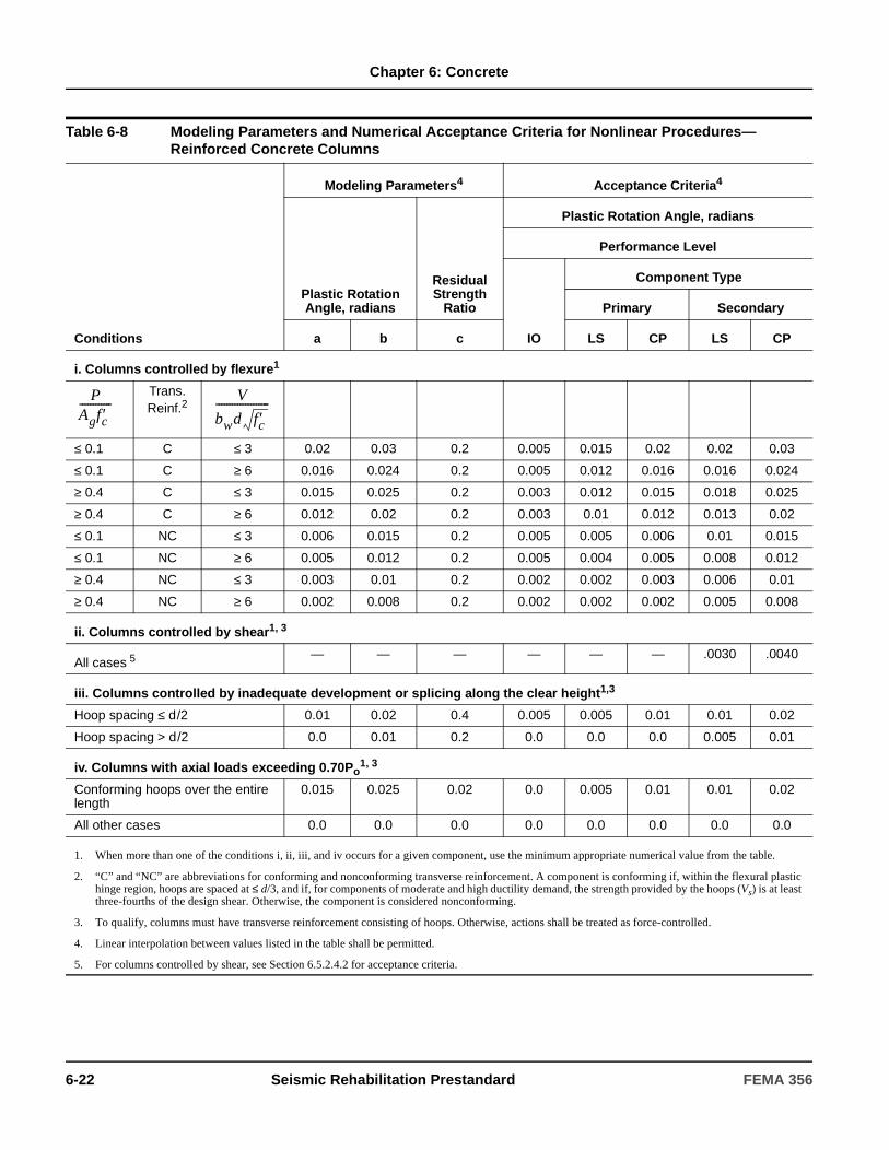
Chapter 6: Concrete
Table 6-8 Modeling Parameters and Numerical Acceptance Criteria for Nonlinear Procedures—Reinforced Concrete Columns
Conditions
Modeling Parameters4 Acceptance Criteria4
Plastic Rotation Angle, radians
Residual Strength
Ratio
Plastic Rotation Angle, radians
Performance Level
IO
Component Type
Primary Secondary
a b c LS CP LS CP
i. Columns controlled by flexure1
Trans. Reinf.2
≤ 0.1 C ≤ 3 0.02 0.03 0.2 0.005 0.015 0.02 0.02 0.03
≤ 0.1 C ≥ 6 0.016 0.024 0.2 0.005 0.012 0.016 0.016 0.024
≥ 0.4 C ≤ 3 0.015 0.025 0.2 0.003 0.012 0.015 0.018 0.025
≥ 0.4 C ≥ 6 0.012 0.02 0.2 0.003 0.01 0.012 0.013 0.02
≤ 0.1 NC ≤ 3 0.006 0.015 0.2 0.005 0.005 0.006 0.01 0.015
≤ 0.1 NC ≥ 6 0.005 0.012 0.2 0.005 0.004 0.005 0.008 0.012
≥ 0.4 NC ≤ 3 0.003 0.01 0.2 0.002 0.002 0.003 0.006 0.01
≥ 0.4 NC ≥ 6 0.002 0.008 0.2 0.002 0.002 0.002 0.005 0.008
ii. Columns controlled by shear1, 3
All cases 5 — — — — — — .0030 .0040
iii. Columns controlled by inadequate development or splicing along the clear height1,3
Hoop spacing ≤ d/2 0.01 0.02 0.4 0.005 0.005 0.01 0.01 0.02
Hoop spacing > d/2 0.0 0.01 0.2 0.0 0.0 0.0 0.005 0.01
iv. Columns with axial loads exceeding 0.70Po1, 3
Conforming hoops over the entire length
0.015 0.025 0.02 0.0 0.005 0.01 0.01 0.02
All other cases 0.0 0.0 0.0 0.0 0.0 0.0 0.0 0.0
1. When more than one of the conditions i, ii, iii, and iv occurs for a given component, use the minimum appropriate numerical value from the table.
2. “C” and “NC” are abbreviations for conforming and nonconforming transverse reinforcement. A component is conforming if, within the flexural plastic hinge region, hoops are spaced at ≤ d/3, and if, for components of moderate and high ductility demand, the strength provided by the hoops (Vs) is at least three-fourths of the design shear. Otherwise, the component is considered nonconforming.
3. To qualify, columns must have transverse reinforcement consisting of hoops. Otherwise, actions shall be treated as force-controlled.
4. Linear interpolation between values listed in the table shall be permitted.
5. For columns controlled by shear, see Section 6.5.2.4.2 for acceptance criteria.
PAgfc′------------ V
bwd fc′--------------------
6-22 Seismic Rehabilitation Prestandard FEMA 356

Chapter 6: Concrete
Table 6-9 Modeling Parameters and Numerical Acceptance Criteria for Nonlinear Procedures—Reinforced Concrete Beam-Column Joints
Conditions
Modeling Parameters4 Acceptance Criteria4
Plastic Shear Angle, radians
Residual Strength
Ratio
Plastic Rotation Angle, radians
Performance Level
IO
Component Type
Primary Secondary
a b c LS CP LS CP
i. Interior joints2, 3
Trans. Reinf. 3
≤ 0.1 C ≤ 1.2 0.015 0.03 0.2 0.0 0.0 0.0 0.02 0.03
≤ 0.1 C ≥ 1.5 0.015 0.03 0.2 0.0 0.0 0.0 0.015 0.02
≥ 0.4 C ≤ 1.2 0.015 0.025 0.2 0.0 0.0 0.0 0.015 0.025
≥ 0.4 C ≥ 1.5 0.015 0.02 0.2 0.0 0.0 0.0 0.015 0.02
≤ 0.1 NC ≤ 1.2 0.005 0.02 0.2 0.0 0.0 0.0 0.015 0.02
≤ 0.1 NC ≥ 1.5 0.005 0.015 0.2 0.0 0.0 0.0 0.01 0.015
≥ 0.4 NC ≤ 1.2 0.005 0.015 0.2 0.0 0.0 0.0 0.01 0.015
≥ 0.4 NC ≥ 1.5 0.005 0.015 0.2 0.0 0.0 0.0 0.01 0.015
ii. Other joints2, 3
Trans. Reinf.1
≤ 0.1 C ≤ 1.2 0.01 0.02 0.2 0.0 0.0 0.0 0.015 0.02
≤ 0.1 C ≥ 1.5 0.01 0.015 0.2 0.0 0.0 0.0 0.01 0.015
≥ 0.4 C ≤ 1.2 0.01 0.02 0.2 0.0 0.0 0.0 0.015 0.02
≥ 0.4 C ≥ 1.5 0.01 0.015 0.2 0.0 0.0 0.0 0.01 0.015
≤ 0.1 NC ≤ 1.2 0.005 0.01 0.2 0.0 0.0 0.0 0.0075 0.01
≤ 0.1 NC ≥ 1.5 0.005 0.01 0.2 0.0 0.0 0.0 0.0075 0.01
≥ 0.4 NC ≤ 1.2 0.0 0.0 – 0.0 0.0 0.0 0.005 0.0075
≥ 0.4 NC ≥ 1.5 0.0 0.0 – 0.0 0.0 0.0 0.005 0.0075
1. “C” and “NC” are abbreviations for conforming and nonconforming transverse reinforcement. A joint is conforming if hoops are spaced at ≤ hc/3 within the joint. Otherwise, the component is considered nonconforming.
2. P is the design axial force on the column above the joint and Ag is the gross cross-sectional area of the joint.
3. V is the design shear force and Vn is the shear strength for the joint. The design shear force and shear strength shall be calculated according to Section 6.5.2.3.
4. Linear interpolation between values listed in the table shall be permitted.
PAg f c′------------- V
Vn------
PAg f c′------------- V
Vn------
FEMA 356 Seismic Rehabilitation Prestandard 6-23

Chapter 6: Concrete
6.5.2.2.3 Nonlinear Dynamic Procedure
For the NDP, the complete hysteretic behavior of each component shall be modeled using properties verified by experimental evidence. The use of the generalized load-deformation relation described by Figure 6-1 to represent the envelope relation for the analysis shall be permitted. Unloading and reloading properties shall represent significant stiffness and strength degradation characteristics.
6.5.2.3 Strength
Component strengths shall be computed according to the general requirements of Sections 6.4.2 as modified in this section.
The maximum component strength shall be determined considering potential failure in flexure, axial load, shear, torsion, development, and other actions at all points along the length of the component under the actions of design gravity and earthquake load combinations.
6.5.2.3.1 Columns
For columns, the contribution of concrete to shear strength, Vc, calculated according to Equation (6-4) shall be permitted.
(6-4)
in which k = 1.0 in regions of low ductility demand, 0.7 in regions of high ductility demand, and varies linearly between these extremes in regions of moderate ductility demand; λ = 0.75 for lightweight aggregate concrete and 1.0 for normal weight aggregate concrete; Nu = axial compression force in pounds (= 0 for tension force); M/V is the largest ratio of moment to shear under design loadings for the column but shall not be taken greater than 3 or less than 2; d is the effective depth; and Ag is the gross cross-sectional area of the column. It shall be permitted to assume d=0.8h, where h is the dimension of the column in the direction of shear. Where axial force is calculated from the linear procedures of Chapter 3, the maximum compressive axial load for use in Equation (6-4) shall be taken as equal to the value calculated using Equation (3-4) considering design gravity load only, and the minimum compression axial load shall be calculated according to Equation (3-18). Alternatively, limit analysis as specified in Section 3.4.2.1.2 shall be permitted to be used to determine design axial loads for use with the linear analysis procedures of Chapter 3. Alternative formulations for column strength that consider effects of reversed cyclic, inelastic deformations and that are verified by experimental evidence shall be permitted.
For columns satisfying the detailing and proportioning requirements of Chapter 21 of ACI 318, the shear strength equations of ACI 318 shall be permitted to be used.
Table 6-10 Values of γ for Joint Strength Calculation
ρ"
Value of γ
Interior joint with transverse
beams
Interior joint without
transverse beams
Exterior joint with transverse
beams
Exterior joint without
transverse beams Knee joint
<0.003 12 10 8 6 4
≥0.003 20 15 15 12 8
ρ" = volumetric ratio of horizontal confinement reinforcement in the joint; knee joint = self-descriptive (with transverse beams or not).
Vc λk6 f ′cM Vd⁄---------------- 1
Nu
6 f’cAg
-------------------+
0.8bwh( )=
6-24 Seismic Rehabilitation Prestandard FEMA 356

Chapter 6: Concrete
For beam-column joints, the nominal cross-sectional area, Aj, shall be defined by a joint depth equal to the column dimension in the direction of framing and a joint width equal to the smallest of (1) the column width, (2) the beam width plus the joint depth, and (3) twice the smaller perpendicular distance from the longitudinal axis of the beam to the column side. Design forces shall be calculated based on development of flexural plastic hinges in adjacent framing members, including effective slab width, but need not exceed values calculated from design gravity and earthquake-load combinations. Nominal joint shear strength Vn shall be calculated according to the general procedures of ACI 318, as modified by Equation (6-5):
(6-5)
in which λ = 0.75 for lightweight aggregate concrete and 1.0 for normal weight aggregate concrete, Aj is the effective horizontal joint area with dimensions as defined above, and γ is as defined in Table 6-10.
6.5.2.4 Acceptance Criteria
6.5.2.4.1 Linear Static and Dynamic Procedures
All actions shall be classified as being either deformation-controlled or force-controlled, as defined in Section 2.4.4. In primary components, deformation-controlled actions shall be restricted to flexure in beams (with or without slab) and columns. In secondary components, deformation-controlled actions shall be restricted to flexure in beams (with or without slab), plus restricted actions in shear and reinforcement development, as identified in Tables 6-11 through 6-13. All other actions shall be defined as being force- controlled actions.
Design actions on components shall be determined as prescribed in Chapter 3. Where the calculated DCR values exceed unity, the following design actions shall be determined using limit analysis principles as prescribed in Chapter 3: (1) moments, shears, torsions, and development and splice actions corresponding to development of component strength in beams and columns; (2) joint shears corresponding to development of strength in adjacent beams and columns; and (3) axial load in columns and joints, considering likely plastic action in components above the level in question.
Design actions shall be compared with design strengths in accordance with Section 3.4.2.2. m-factors shall be selected from Tables 6-11 through 6-13. Those components that satisfy Equations (3-20) and (3-21) shall satisfy the performance criteria.
Where the average DCR of columns at a level exceeds the average value of beams at the same level, and exceeds the greater of 1.0 and m/2 for all columns, the level shall be defined as a weak column element. For weak column elements, one of the following shall be satisfied.
1. The check of average DCR values at the level shall be repeated, considering all primary and secondary components at the level with a weak column element. If the average of the DCR values for vertical components exceeds the average value for horizontal components at the level, and exceeds 2.0, the structure shall be reanalyzed using a nonlinear procedure, or the structure shall be rehabilitated to remove this deficiency.
2. The structure shall be reanalyzed using either the NSP or the NDP of Chapter 3.
3. The structure shall be rehabilitated to remove the weak story.
6.5.2.4.2 Nonlinear Static and Dynamic Procedures
Calculated component actions shall satisfy the requirements of Section 3.4.3.2. Where the generalized deformation is taken as rotation in the flexural plastic hinge zone in beams and columns, the plastic hinge rotation capacities shall be as defined by Tables 6-7 and 6-8. Where the generalized deformation is shear distortion of the beam-column joint, shear angle capacities shall be as defined by Table 6-9. For columns designated as primary components and for which calculated design shears exceed design shear strength as defined by Equation (6-4), the permissible deformation for the Collapse Prevention Performance Level shall not exceed the deformation at which shear strength is calculated to be reached; the permissible deformation for the Life Safety Performance Level shall not exceed three quarters of that value. Where inelastic action is indicated for a component or action not listed in these tables, the performance shall be deemed unacceptable. Alternative approaches or values shall be permitted where justified by experimental evidence and analysis.
QCL Vn λγ fc′ Aj psi,= =
FEMA 356 Seismic Rehabilitation Prestandard 6-25

Chapter 6: Concrete
Table 6-11 Numerical Acceptance Criteria for Linear Procedures—Reinforced Concrete Beams
Conditions
m-factors3
Performance Level
IO
Component Type
Primary Secondary
LS CP LS CP
i. Beams controlled by flexure1
Trans. Reinf.2
≤ 0.0 C ≤ 3 3 6 7 6 10
≤ 0.0 C ≥ 6 2 3 4 3 5
≥ 0.5 C ≤ 3 2 3 4 3 5
≥ 0.5 C ≥ 6 2 2 3 2 4
≤ 0.0 NC ≤ 3 2 3 4 3 5
≤ 0.0 NC ≥ 6 1.25 2 3 2 4
≥ 0.5 NC ≤ 3 2 3 3 3 4
≥ 0.5 NC ≥ 6 1.25 2 2 2 3
ii. Beams controlled by shear1
Stirrup spacing ≤ d/2 1.25 1.5 1.75 3 4
Stirrup spacing > d/2 1.25 1.5 1.75 2 3
iii. Beams controlled by inadequate development or splicing along the span1
Stirrup spacing ≤ d/2 1.25 1.5 1.75 3 4
Stirrup spacing > d/2 1.25 1.5 1.75 2 3
iv. Beams controlled by inadequate embedment into beam-column joint1
2 2 3 3 4
1. When more than one of the conditions i, ii, iii, and iv occurs for a given component, use the minimum appropriate numerical value from the table.
2. “C” and “NC” are abbreviations for conforming and nonconforming transverse reinforcement. A component is conforming if, within the flexural plastic hinge region, hoops are spaced at ≤ d/3, and if, for components of moderate and high ductility demand, the strength provided by the hoops (Vs) is at least three-fourths of the design shear. Otherwise, the component is considered nonconforming.
3. Linear interpolation between values listed in the table shall be permitted.
ρ ρ′–ρbal
-------------- V
bwd fc′--------------------
6-26 Seismic Rehabilitation Prestandard FEMA 356

Chapter 6: Concrete
Table 6-12 Numerical Acceptance Criteria for Linear Procedures—Reinforced Concrete Columns
Conditions
m-factors4
Performance Level
IO
Component Type
Primary Secondary
LS CP LS CP
i. Columns controlled by flexure1
Trans. Reinf.2
≤ 0.1 C ≤ 3 2 3 4 4 5
≤ 0.1 C ≥ 6 2 2.4 3.2 3.2 4
≥ 0.4 C ≤ 3 1.25 2 3 3 4
≥ 0.4 C ≥ 6 1.25 1.6 2.4 2.4 3.2
≤ 0.1 NC ≤ 3 2 2 3 2 3
≤ 0.1 NC ≥ 6 2 1.6 2.4 1.6 2.4
≥ 0.4 NC ≤ 3 1.25 1.5 2 1.5 2
≥ 0.4 NC ≥ 6 1.25 1.5 1.75 1 1.6
ii. Columns controlled by shear1,3
Hoop spacing ≤ d/2,
or ≤ 0.1
– – – 2 3
Other cases – – – 1.5 2
iii. Columns controlled by inadequate development or splicing along the clear height1,3
Hoop spacing ≤ d/2 1.25 1.5 1.75 3 4
Hoop spacing > d/2 – – – 2 3
iv. Columns with axial loads exceeding 0.70Po1,3
Conforming hoops over the entire length 1 1 2 2 2
All other cases – – – 1 1
1. When more than one of the conditions i, ii, iii, and iv occurs for a given component, use the minimum appropriate numerical value from the table.
2. “C” and “NC” are abbreviations for conforming and nonconforming transverse reinforcement. A component is conforming if, within the flexural plastic hinge region, hoops are spaced at ≤ d/3, and if, for components of moderate and high ductility demand, the strength provided by the hoops (Vs) is at least three-fourths of the design shear. Otherwise, the component is considered nonconforming.
3. To qualify, columns must have transverse reinforcement consisting of hoops. Otherwise, actions shall be treated as force-controlled.
4. Linear interpolation between values listed in the table shall be permitted.
PAgfc′------------ V
bwd fc′--------------------
PAg f c′------------
FEMA 356 Seismic Rehabilitation Prestandard 6-27

Chapter 6: Concrete
Table 6-13 Numerical Acceptance Criteria for Linear Procedures—Reinforced Concrete Beam-Column Joints
Conditions
m-factors4
Performance Level
IO
Component Type
Primary5 Secondary
LS CP LS CP
i. Interior joints2, 3
Trans. Reinf.
≤ 0.1 C ≤ 1.2 – – – 3 4
≤ 0.1 C ≥ 1.5 – – – 2 3
≥ 0.4 C ≤ 1.2 – – – 3 4
≥ 0.4 C ≥ 1.5 – – – 2 3
≤ 0.1 NC ≤ 1.2 – – – 2 3
≤ 0.1 NC ≥ 1.5 – – – 2 3
≥ 0.4 NC ≤ 1.2 – – – 2 3
≥ 0.4 NC ≥ 1.5 – – – 2 3
ii. Other joints2, 3
Trans. Reinf.
≤ 0.1 C ≤ 1.2 – – – 3 4
≤ 0.1 C ≥ 1.5 – – – 2 3
≥ 0.4 C ≤ 1.2 – – – 3 4
≥ 0.4 C ≥ 1.5 – – – 2 3
≤ 0.1 NC ≤ 1.2 – – – 2 3
≤ 0.1 NC ≥ 1.5 – – – 2 3
≥ 0.4 NC ≤ 1.2 – – – 1.5 2.0
≥ 0.4 NC ≥ 1.5 – – – 1.5 2.0
1. “C” and “NC” are abbreviations for conforming and nonconforming transverse reinforcements. A joint is conforming if hoops are spaced at ≤ hc/3 within the joint. Otherwise, the component is considered nonconforming.
2. P is the ratio of the design axial force on the column above the joint and Ag is the gross cross-sectional area of the joint.
3. V is the design shear force and Vn is the shear strength for the joint. The design shear force and shear strength shall be calculated according to Section 6.5.2.3.
4. Linear interpolation between values listed in the table shall be permitted.
5. For linear procedures, all primary joints shall be force-controlled; m-factors shall not apply.
PAg f c′------------
VVn------
PAg f c′------------
VVn------
6-28 Seismic Rehabilitation Prestandard FEMA 356
Chapter 6: Concrete
6.5.2.5 Rehabilitation Measures
Concrete beam-column moment frame components that do not meet the acceptance criteria for the selected rehabilitation objective shall be rehabilitated. Rehabilitation measures shall meet the requirements of Section 6.4.7 and other provisions of this standard.
6.5.3 Post-Tensioned Concrete Beam-Column Moment Frames
6.5.3.1 General Considerations
The analytical model for a post-tensioned concrete beam-column frame element shall be established following the criteria specified in Section 6.5.2.1 for reinforced concrete beam-column moment frames. In addition to potential failure modes described in Section 6.5.2.1, the analysis model shall consider potential failure of tendon anchorages.
The analysis procedures described in Chapter 3 shall apply to frames with post-tensioned beams satisfying the following conditions:
1. The average prestress, fpc, calculated for an area equal to the product of the shortest cross-sectional dimension and the perpendicular cross-sectional dimension of the beam, does not exceed the greater of 750 psi or f ’c /12 at locations of nonlinear action.
C6.5.2.5 Rehabilitation Measures
The following rehabilitation measures may be effective in rehabilitating reinforced concrete beam-column moment frames:
1. Jacketing existing beams, columns, or joints with new reinforced concrete, steel, or fiber wrap overlays. The new materials should be designed and constructed to act compositely with the existing concrete. Where reinforced concrete jackets are used, the design should provide detailing to enhance ductility. Component strength should be taken to not exceed any limiting strength of connections with adjacent components. Jackets should be designed to provide increased connection strength and improved continuity between adjacent components.
2. Post-tensioning existing beams, columns, or joints using external post-tensioned reinforcement. Post-tensioned reinforcement should be unbonded within a distance equal to twice the effective depth from sections where inelastic action is expected. Anchorages should be located away from regions where inelastic action is anticipated, and should be designed considering possible force variations due to earthquake loading.
3. Modification of the element by selective material removal from the existing element. Examples include: (1) where nonstructural elements or components interfere with the frame, removing or separating the nonstructural elements or components to eliminate the interference; (2) weakening, due to removal of concrete or severing of longitudinal reinforcement, to change response mode from a nonductile mode to a more ductile mode (e.g., weakening of beams to promote formation of a strong-column, weak-beam system); and (3) segmenting walls to change stiffness and strength.
4. Improvement of deficient existing reinforcement details. Removal of cover concrete for modification of existing reinforcement details should avoid damage to core concrete and the bond between existing reinforcement and core concrete. New cover concrete should be designed and constructed to achieve fully composite action with the existing materials.
5. Changing the building system to reduce the demands on the existing element. Examples include addition of supplementary lateral-force- resisting elements such as walls or buttresses, seismic isolation, and mass reduction.
6. Changing the frame element to a shear wall, infilled frame, or braced frame element by addition of new material. Connections between new and existing materials should be designed to transfer the forces anticipated for the design load combinations. Where the existing concrete frame columns and beams act as boundary elements and collectors for the new shear wall or braced frame, these should be checked for adequacy, considering strength, reinforcement development, and deformability. Diaphragms, including drag struts and collectors, should be evaluated and, if necessary, rehabilitated to ensure a complete load path to the new shear wall or braced frame element.
FEMA 356 Seismic Rehabilitation Prestandard 6-29

Chapter 6: Concrete
2. Prestressing tendons do not provide more than one- quarter of the strength for both positive moments and negative moments at the joint face.
3. Anchorages for tendons are demonstrated to have performed satisfactorily for seismic loadings in compliance with the requirements of ACI 318. These anchorages occur outside hinging areas or joints, except in existing components where experimental evidence demonstrates that the connection will meet the performance objectives under design loadings.
Alternative procedures shall be provided where these conditions are not satisfied.
6.5.3.2 Stiffness
6.5.3.2.1 Linear Static and Dynamic Procedures
Beams shall be modeled considering flexural and shear stiffnesses, including the effect of the slab acting as a flange in monolithic and composite construction. Columns shall be modeled considering flexural, shear, and axial stiffnesses. Joints shall be modeled as either stiff or rigid components. Effective stiffnesses shall be according to Section 6.4.1.2.
6.5.3.2.2 Nonlinear Static Procedure
Nonlinear load-deformation relations shall comply with the requirements of Section 6.4.1.2 and the reinforced concrete frame requirements of Section 6.5.2.2.2.
Values of the generalized deformation at points B, C, and D in Figure 6-1 shall be either derived from experiments or approved rational analyses, and shall take into account the interactions between flexure, axial load, and shear. Alternatively, where the generalized deformation is taken as rotation in the flexural plastic hinge zone, and where the three conditions of Section 6.5.3.1 are satisfied, beam plastic hinge rotation capacities shall be as defined by Table 6-7. Columns and joints shall be modeled as described in Section 6.5.2.2.
6.5.3.2.3 Nonlinear Dynamic Procedure
For the NDP, the complete hysteretic behavior of each component shall be modeled using properties verified by experimental evidence. The relation of Figure 6-1 shall be taken to represent the envelope relation for the analysis. Unloading and reloading properties shall represent significant stiffness and strength degradation characteristics as influenced by prestressing.
6.5.3.3 Strength
Component strengths shall be computed according to the general requirements of Sections 6.4.2 and the additional requirements of Section 6.5.2.3. Effects of prestressing on strength shall be considered.
For deformation-controlled actions, prestress shall be assumed to be effective for the purpose of determining the maximum actions that may be developed associated with nonlinear response of the frame. For force- controlled actions, the effects on strength of prestress loss shall also be considered as a design condition, where these losses are possible under design load combinations including inelastic deformation reversals.
6.5.3.4 Acceptance Criteria
Acceptance criteria for post-tensioned concrete beam-column moment frames shall follow the criteria for reinforced concrete beam-column frames specified in Section 6.5.2.4.
Modeling parameters and acceptance criteria shall be based on Tables 6-7 through 6-9 and 6-11 through 6-13.
6.5.3.5 Rehabilitation Measures
Post-tensioned concrete beam-column moment frame components that do not meet the acceptance criteria for the selected Rehabilitation Objective shall be rehabilitated. Rehabilitation measures shall meet the requirements of Section 6.4.7 and other provisions of this standard.
6.5.4 Slab-Column Moment Frames
6.5.4.1 General Considerations
The analytical model for a slab-column frame element shall represent strength, stiffness, and deformation capacity of slabs, columns, slab-column connections, and other components of the frame. Potential failure in flexure, shear, shear-moment transfer, and reinforcement development at any section along the component length shall be considered. Interaction with other elements, including nonstructural elements and components, shall be included.
C6.5.3.5 Rehabilitation Measures
The rehabilitation measures described in C6.5.2.5 for reinforced concrete beam-column moment frames may also be effective in rehabilitating post-tensioned concrete beam-column moment frames.
6-30 Seismic Rehabilitation Prestandard FEMA 356
Chapter 6: Concrete
The analytical model that represents the slab-column frame, using either line elements with properties concentrated at component centerlines or a combination of line elements (to represent columns) and plate-bending elements (to represent the slab), based on any of the following approaches, shall be permitted.
1. An effective beam width model, in which the columns and slabs are represented by line elements that are rigidly interconnected at the slab-column joint.
2. An equivalent frame model in which the columns and slabs are represented by line elements that are interconnected by connection springs.
3. A finite element model in which the columns are represented by line elements and the slab is represented by plate-bending elements.
In any model, the effects of changes in cross section, including slab openings, shall be considered.
The connection between the columns and foundation shall be modeled based on the details of the column-foundation connection and rigidity of the foundation-soil system.
Action of the slab as a diaphragm interconnecting vertical elements shall be represented.
In the design model, inelastic deformations in primary components shall be restricted to flexure in slabs and columns, plus nonlinear response in slab-column connections. Other inelastic deformations shall be permitted as part of the design in secondary components. Acceptance criteria shall be as specified in Section 6.5.4.4.
6.5.4.2 Stiffness
6.5.4.2.1 Linear Static and Dynamic Procedures
Slabs shall be modeled considering flexural, shear, and torsional (in the slab adjacent to the column) stiffnesses. Columns shall be modeled considering flexural, shear, and axial stiffnesses. Joints shall be modeled as either stiff or rigid components. The effective stiffnesses of components shall be determined according to the general principles of Section 6.4.1.2, but adjustments on the basis of experimental evidence shall be permitted.
6.5.4.2.2 Nonlinear Static Procedure
Nonlinear load-deformation relations shall comply with the requirements of Section 6.4.1.2.
Slabs and columns shall be modeled using concentrated plastic hinge models, distributed plastic hinge models, or other models whose behavior has been demonstrated to adequately represent behavior of reinforced concrete slab and column components subjected to lateral loading. The model shall be capable of representing inelastic response along the component length, except where it is shown by equilibrium that yielding is restricted to the component ends. Slab- column connections shall be modeled separately from the slab and column components in order to identify potential failure in shear and moment transfer; alternatively, the potential for connection failure shall be otherwise checked as part of the analysis. Where nonlinear response is expected in a mode other than flexure, the model shall be established to represent these effects.
Monotonic load-deformation relations shall be according to the generalized relation shown in Figure 6-1, with definitions according to Section 6.5.2.2.2. The overall load-deformation relation shall be established so that the maximum resistance is consistent with the design strength specifications of Sections 6.4.2 and 6.5.4.3. Where the generalized deformation shown in Figure 6-1 is taken as the flexural plastic hinge rotation for the column, the plastic hinge rotation capacities shall be as defined by Table 6-8. Where the generalized deformation shown in Figure 6-1 is taken as the rotation of the slab-column connection, the plastic rotation capacities shall be as defined by Table 6-14.
6.5.4.2.3 Nonlinear Dynamic Procedure
The requirements of Sections 6.4.2 6.5.2.2.3 for reinforced concrete beam-column moment frames shall apply to slab-column moment frames.
6.5.4.3 Strength
Component strengths shall be computed according to the general requirements of Sections 6.4.2, as modified in this section.
FEMA 356 Seismic Rehabilitation Prestandard 6-31
Chapter 6: Concrete
The maximum component strength shall be determined considering potential failure in flexure, axial load, shear, torsion, development, and other actions at all points along the length of the component under the actions of design gravity and earthquake load combinations. The strength of slab-column connections also shall be determined and incorporated in the analytical model.
The flexural strength of a slab to resist moment due to lateral deformations shall be calculated as MnCS – MgCS, where MnCS is the design flexural strength of the column strip and MgCS is the column strip moment due to gravity loads. MgCS shall be calculated according to the procedures of ACI 318 for the design gravity load specified in Chapter 3.
For columns, the evaluation of shear strength according to Section 6.5.2.3 shall be permitted.
Shear and moment transfer strength of the slab-column connection shall be calculated considering the combined action of flexure, shear, and torsion acting in the slab at the connection with the column. The procedures described below shall be permitted to satisfy this requirement.
For interior connections without transverse beams, and for exterior connections with moment about an axis perpendicular to the slab edge, the shear and moment transfer strength calculated as the minimum of the following strengths shall be permitted:
1. The strength calculated considering eccentricity of shear on a slab critical section due to combined shear and moment, as prescribed in ACI 318.
2. The moment transfer strength equal to ΣMn/γf, where ΣMn = the sum of positive and negative flexural strengths of a section of slab between lines that are two and one-half slab or drop panel thicknesses (2.5h) outside opposite faces of the column or capital; γf = the fraction of the moment resisted by flexure per ACI 318; and h = slab thickness.
For moment about an axis parallel to the slab edge at exterior connections without transverse beams, where the shear on the slab critical section due to gravity loads does not exceed 0.75Vc, or the shear at a corner support does not exceed 0.5 Vc, the moment transfer strength shall be permitted to be taken as equal to the flexural strength of a section of slab between lines that are a distance, c1, outside opposite faces of the column or capital. Vc is the direct punching shear strength defined by ACI 318.
6.5.4.4 Acceptance Criteria
6.5.4.4.1 Linear Static and Dynamic Procedures
All component actions shall be classified as being either deformation-controlled or force-controlled, as defined in Section 2.4.4. In primary components, deformation-controlled actions shall be restricted to flexure in slabs and columns, and shear and moment transfer in slab-column connections. In secondary components, deformation-controlled actions shall also be permitted in shear and reinforcement development, as identified in Table 6-15. All other actions shall be defined as being force-controlled actions.
Design actions on components shall be determined as prescribed in Chapter 3. Where the calculated DCR values exceed unity, the following design actions shall be determined using limit analysis principles as prescribed in Chapter 3: (1) moments, shears, torsions, and development and splice actions corresponding to development of component strength in slabs and columns; and (2) axial load in columns, considering likely plastic action in components above the level in question.
Design actions shall be compared with design strengths in accordance with Section 3.4.2.2, Tables 6-12 and 6-15. Those components that satisfy Equations (3-20) and (3-21) shall satisfy the performance criteria. Components that reach their design strengths shall be further evaluated according to this section to determine performance acceptability.
Where the average of the DCRs of columns at a level exceeds the average value of slabs at the same level, and exceeds the greater of 1.0 and m/2, the element shall be defined as a weak story element and shall be evaluated by the procedure for weak story elements described in Section 6.5.2.4.1.
6-32 Seismic Rehabilitation Prestandard FEMA 356

Chapter 6: Concrete
6.5.4.4.2 Nonlinear Static and Dynamic Procedures
In the design model, inelastic response shall be restricted to those components and actions listed in Tables 6-8 and 6-14, except where it is demonstrated by experimental evidence and analysis that other inelastic action is acceptable for the selected performance levels.
Calculated component actions shall satisfy the requirements of Chapter 3. Maximum permissible inelastic deformations shall be as listed in Tables 6-8 and 6-14. Where inelastic action is indicated for a component or action not listed in these tables, the performance shall be deemed unacceptable. Alternative approaches or values shall be permitted where justified by experimental evidence and analysis.
6.5.4.5 Rehabilitation Measures
Reinforced concrete slab-column, beam-column moment frame components that do not meet the acceptance criteria for the selected Rehabilitation Objective shall be rehabilitated. Rehabilitation measures shall meet the requirements of Section 6.4.7 and other provisions of this standard.
C6.5.4.5 Rehabilitation Measures
The rehabilitation measures described in C6.5.2.5 for reinforced concrete beam-column moment frames may also be effective in rehabilitating reinforced concrete slab-column moment frames.
Table 6-14 Modeling Parameters and Numerical Acceptance Criteria for Nonlinear Procedures—Two-way Slabs and Slab-Column Connections
Conditions
Modeling Parameters4 Acceptance Criteria4
Plastic Rotation Angle, radians
Residual Strength
Ratio
Plastic Rotation Angle, radians
Performance Level
IO
Component Type
Primary Secondary
a b c LS CP LS CP
i. Slabs controlled by flexure, and slab-column connections1
2Continuity
Reinforcement3
≤ 0.2 Yes 0.02 0.05 0.2 0.01 0.015 0.02 0.03 0.05
≥ 0.4 Yes 0.0 0.04 0.2 0.0 0.0 0.0 0.03 0.04
≤ 0.2 No 0.02 0.02 – 0.01 0.015 0.02 0.015 0.02
≥ 0.4 No 0.0 0.0 – 0.0 0.0 0.0 0.0 0.0
ii. Slabs controlled by inadequate development or splicing along the span1
0.0 0.02 0.0 0.0 0.0 0.0 0.01 0.02
iii. Slabs controlled by inadequate embedment into slab-column joint1
0.015 0.03 0.2 0.01 0.01 0.015 0.02 0.03
1. When more than one of the conditions i, ii, and iii occurs for a given component, use the minimum appropriate numerical value from the table.
2. Vg = the gravity shear acting on the slab critical section as defined by ACI 318; Vo = the direct punching shear strength as defined by ACI 318.
3. Under the heading “Continuity Reinforcement,” use “Yes” where at least one of the main bottom bars in each direction is effectively continuous through the column cage. Where the slab is post-tensioned, use “Yes” where at least one of the post-tensioning tendons in each direction passes through the column cage. Otherwise, use “No.”
4. Linear interpolation between values shown in the table shall be permitted.
Vg
Vo------
FEMA 356 Seismic Rehabilitation Prestandard 6-33

Chapter 6: Concrete
6.6 Precast Concrete Frames
6.6.1 Types of Precast Concrete Frames
Precast concrete frames shall be defined as those elements that are constructed from individually made beams and columns that are assembled to create gravity-load-carrying systems. These systems shall include those that are considered in design to resist design lateral loads, and those that are considered in design as secondary elements that do not resist design lateral loads but must resist the effects of deformations resulting from design lateral loads.
The provisions of this section shall apply to precast concrete frames that emulate cast-in-place moment frames defined in Section 6.6.1.1, precast concrete beam-column moment frames constructed with dry joints defined in Section 6.6.1.2, and precast concrete frames not expected to directly resist lateral loads defined in Section 6.6.1.3.
Table 6-15 Numerical Acceptance Criteria for Linear Procedures—Two-way Slabs and Slab-Column Connections
Conditions
m-factors
Performance Level
IO
Component Type
Primary Secondary
LS CP LS CP
i. Slabs controlled by flexure, and slab-column connections1
2Continuity Reinforcement3
≤ 0.2 Yes 2 2 3 3 4
≥ 0.4 Yes 1 1 1 2 3
≤ 0.2 No 2 2 3 2 3
≥ 0.4 No 1 1 1 1 1
ii. Slabs controlled by inadequate development or splicing along the span1
– – – 3 4
iii. Slabs controlled by inadequate embedment into slab-column joint1
2 2 3 3 4
1. When more than one of the conditions i, ii, and iii occurs for a given component, use the minimum appropriate numerical value from the table.
2. Vg = the gravity shear acting on the slab critical section as defined by ACI 318; Vo = the direct punching shear strength as defined by ACI 318.
3. Under the heading “Continuity Reinforcement,” use “Yes” where at least one of the main bottom bars in each direction is effectively continuous through the column cage. Where the slab is post-tensioned, use “Yes” where at least one of the post-tensioning tendons in each direction passes through the column cage. Otherwise, use “No.”
Vg
Vo------
6-34 Seismic Rehabilitation Prestandard FEMA 356

Chapter 6: Concrete
6.6.1.1 Precast Concrete Frames that Emulate Cast-in-Place Moment Frames
Precast concrete frames that emulate cast-in-place moment frames shall be defined as those precast beam-column systems that are interconnected using reinforcement and wet concrete to create a system that resists lateral loads in a manner similar to cast-in-place concrete systems.
6.6.1.2 Precast Concrete Moment Frames Constructed with Dry Joints
Frames of this classification shall be assembled using dry joints (connections are made by bolting, welding, post-tensioning, or other similar means) in a way that results in significant lateral force resistance in the framing element. Frames of this classification resist lateral loads either acting alone, or acting in conjunction with shear walls, braced frames, or other lateral load resisting elements in a dual system.
6.6.1.3 Precast Concrete Frames Not Expected to Resist Lateral Load Directly
Frames of this classification shall be assembled using dry joints in a way that does not result in significant lateral force resistance in the framing element. Shear walls, braced frames, or moment frames provide the entire lateral load resistance, with the precast concrete frame system deforming in a manner that is compatible with the structure as a whole.
6.6.2 Precast Concrete Frames that Emulate Cast-in-Place Moment Frames
6.6.2.1 General Considerations
The analytical model for a frame element of this classification shall represent strength, stiffness, and deformation capacity of beams, columns, beam-column joints, and other components of the frame. Potential failure in flexure, shear, and reinforcement development at any section along the component length shall be considered. Interaction with other elements, including nonstructural elements and components, shall be included. All other considerations of Section 6.5.2.1 shall be taken into account. In addition, the effects of shortening due to creep, and other effects of prestressing and post-tensioning on member behavior, shall be evaluated.
6.6.2.2 Stiffness
Stiffness for analysis shall be as defined in Section 6.5.2.2. The effects of prestressing shall be considered when computing the effective stiffness values using Table 6-5.
6.6.2.3 Strength
Component strength shall be computed according to the requirements of Section 6.5.2.3, with the additional requirement that the following effects be included in the analysis:
1. Effects of prestressing that are present, including, but not limited to, reduction in rotation capacity, secondary stresses induced, and amount of effective prestress force remaining;
2. Effects of construction sequence, including the possibility of construction of the moment connections occurring after portions of the structure are subjected to dead loads;
3. Effects of restraint due to interaction with interconnected wall or brace components.
6.6.2.4 Acceptance Criteria
Acceptance criteria for precast concrete frames that emulate cast-in-place moment frames shall be as specified in Section 6.5.2.4, except that the factors defined in Section 6.5.2.3 shall also be considered.
C6.6.1.1 Precast Concrete Frames that Emulate Cast-in-Place Moment Frames
These systems are recognized and accepted by FEMA 222A, and are based on ACI 318, which requires safety and serviceability levels expected from monolithic construction. There is insufficient research and testing data at this time to qualify systems assembled using dry joints as emulated moment frames.
C6.6.1.2 Precast Concrete Moment Frames Constructed with Dry Joints
The appendix to Chapter 6 of FEMA 222A contains a trial version of code provisions for new construction of this classification.
FEMA 356 Seismic Rehabilitation Prestandard 6-35
Chapter 6: Concrete
6.6.2.5 Rehabilitation Measures
Precast concrete frame components that do not meet the acceptance criteria for the selected Rehabilitation Objective shall be rehabilitated. Rehabilitation measures shall meet the requirements of Section 6.4.7 and other provisions of this standard.
6.6.3 Precast Concrete Moment Frames Constructed with Dry Joints
6.6.3.1 General Considerations
The analysis model for precast concrete moment frames constructed with dry joints shall be as specified in Section 6.5.2.1 for reinforced concrete beam-column moment frames, with additional consideration of the special nature of the dry joints used in assembling the precast system. Where connections yield under design lateral loads, the analysis model shall take this into account.
6.6.3.2 Stiffness
Stiffness for analysis shall be as defined in Section 6.6.2.2. Flexibilities associated with connections shall be included in the analytical model.
6.6.3.3 Strength
Component strength shall be computed according to the requirements of Section 6.6.2.3, with the additional requirement that connection strength shall comply with the requirements of Section 6.4.6.
6.6.3.4 Acceptance Criteria
Acceptance criteria for precast concrete moment frames constructed with dry joints shall be as specified in Section 6.6.2.4, with the additional requirement that the connections comply with the requirements of Section 6.4.6.
6.6.3.5 Rehabilitation Measures
Precast concrete moment frame components that do not meet the acceptance criteria for the selected Rehabilitation Objective shall be rehabilitated. Rehabilitation measures shall meet the requirements of Section 6.4.7 and other provisions of this standard.
C6.6.2.5 Rehabilitation Measures
The rehabilitation measures described in C6.5.2.5 for reinforced concrete beam-column moment frames may also be effective in rehabilitating precast concrete frames that emulate cast-in-place moment frames. When installing new elements, components, or materials to the existing system, existing prestressing strands should be protected.
C6.6.3.1 General Considerations
The requirements given in the appendix to Chapter 6 of FEMA 222A for this type of structural system should be adhered to where possible, and the philosophy and approach should be employed when designing new connections for existing components.
C6.6.3.3 Strength
In addition to complying with the provisions of Section 6.6.3.3, the connections should comply with the requirements given in the appendix to Chapter 6 of FEMA 222A.
C6.6.3.4 Acceptance Criteria
In addition to complying with the provisions of Section 6.6.3.4, the acceptance criteria should comply with the requirements given in Section 6A.4 of the appendix to Chapter 6 of FEMA 222A.
C6.6.3.5 Rehabilitation Measures
The rehabilitation measures described in C6.5.2.5 for reinforced concrete beam-column moment frames may also be effective in rehabilitating precast concrete frames constructed with dry joints. When installing new elements, components, or materials to the existing system, existing prestressing strands should be protected.
6-36 Seismic Rehabilitation Prestandard FEMA 356
Chapter 6: Concrete
6.6.4 Precast Concrete Frames Not Expected to Resist Lateral Loads Directly
6.6.4.1 General Considerations
The analytical model for precast concrete frames that are not expected to resist lateral loads directly shall comply with the requirements of Section 6.6.3.1 and shall include the effects of deformations that are calculated to occur under the design earthquake loadings.
6.6.4.2 Stiffness
The analytical model shall either include realistic lateral stiffness of these frames to evaluate the effects of deformations under lateral loads or, if the lateral stiffness is ignored in the analytical model, the effects of calculated building drift on these frames shall be evaluated separately. The analytical model shall consider the negative effects of connection stiffness on component response where that stiffness results in actions that may cause component failure.
6.6.4.3 Strength
Component strength shall be computed according to the requirements of Section 6.6.3.3. All components shall have sufficient strength and ductility to transmit induced forces from one member to another and to the designated lateral-force-resisting system.
6.6.4.4 Acceptance Criteria
Acceptance criteria for components in precast concrete frames not expected to directly resist lateral loads shall be as specified in Section 6.6.3.4. All moments, shear forces, and axial loads induced through the deformation of the structural system shall be checked for acceptability by appropriate criteria in the referenced section.
6.6.4.5 Rehabilitation Measures
Precast concrete frame components that do not meet the acceptance criteria for the selected Rehabilitation Objective shall be rehabilitated. Rehabilitation measures shall meet the requirements of Section 6.4.7 and other provisions of this standard.
6.7 Concrete Frames with Infills
6.7.1 Types of Concrete Frames with Infills
Concrete frames with infills are elements with complete gravity-load-carrying concrete frames infilled with masonry or concrete, constructed in such a way that the infill and the concrete frame interact when subjected to vertical and lateral loads.
Isolated infills are infills isolated from the surrounding frame complying with the minimum gap requirements specified in Section 7.5.1. If all infills in a frame are isolated infills, the frame shall be analyzed as an isolated frame according to provisions given elsewhere in this chapter, and the isolated infill panels shall be analyzed according to the requirements of Chapter 7.
The provisions of Section 6.7 shall apply to concrete frames with existing infills, frames that are rehabilitated by addition or removal of material, and concrete frames that are rehabilitated by the addition of new infills.
C6.6.4.2 Stiffness
The stiffness used in the analysis should consider possible resistance that may develop under lateral deformation. In some cases it may be appropriate to assume zero lateral stiffness. However, the Northridge earthquake graphically demonstrated that there are few instances where the precast column can be considered to be completely pinned top and bottom, and as a consequence, not resist any shear from building drift. Several parking structures collapsed as a result of this defect. Conservative assumptions should be made.
C6.6.4.5 Rehabilitation Measures
The rehabilitation measures described in C6.5.2.5 for reinforced concrete beam-column moment frames may also be effective in rehabilitating precast concrete frames not expected to resist lateral loads directly. When installing new elements, components, or materials to the existing system, existing prestressing strands should be protected.
FEMA 356 Seismic Rehabilitation Prestandard 6-37
Chapter 6: Concrete
6.7.1.1 Types of Frames
The provisions of Section 6.7 shall apply to concrete frames as defined in Sections 6.5, 6.6, and 6.10, where those frames interact with infills.
6.7.1.2 Masonry Infills
The provisions of Section 6.7 shall apply to masonry infills as defined in Chapter 7, where those infills interact with concrete frames.
6.7.1.3 Concrete Infills
The provisions of Section 6.7 shall apply to concrete infills that interact with concrete frames, where the infills were constructed to fill the space within the bay of a complete gravity frame without special provision for continuity from story to story. The concrete of the infill shall be evaluated separately from the concrete of the frame.
6.7.2 Concrete Frames with Masonry Infills
6.7.2.1 General Considerations
The analytical model for a concrete frame with masonry infills shall represent strength, stiffness, and deformation capacity of beams, slabs, columns, beam-column joints, masonry infills, and all connections and components of the element. Potential failure in flexure, shear, anchorage, reinforcement development, or crushing at any section shall be considered. Interaction with other nonstructural elements and components shall be included.
For a concrete frame with masonry infill resisting lateral forces within its plane, modeling of the response using a linear elastic model shall be permitted provided that the infill will not crack when subjected to design lateral forces. If the infill will not crack when subjected to design lateral forces, modeling the assemblage of frame and infill as a homogeneous medium shall be permitted.
For a concrete frame with masonry infills that will crack when subjected to design lateral forces, modeling of the response using a diagonally braced frame model, in which the columns act as vertical chords, the beams act as horizontal ties, and the infill acts as an equivalent compression strut, shall be permitted. Requirements for the equivalent compression strut analogy shall be as specified in Chapter 7.
Frame components shall be evaluated for forces imparted to them through interaction of the frame with the infill, as specified in Chapter 7. In frames with full-height masonry infills, the evaluation shall include the effect of strut compression forces applied to the column and beam, eccentric from the beam-column joint. In frames with partial-height masonry infills, the evaluation shall include the reduced effective length of the columns above the infilled portion of the bay.
6.7.2.2 Stiffness
6.7.2.2.1 Linear Static and Dynamic Procedures
In frames having infills in some bays and no infill in other bays, the restraint of the infill shall be represented as described in Section 6.7.2.1, and the noninfilled bays shall be modeled as frames as specified in appropriate portions of Sections 6.5, 6.6, and 6.10. Where infills create a discontinuous wall, the effects of the discontinuity on overall building performance shall be evaluated. Effective stiffnesses shall be in accordance with Section 6.4.1.2.
6.7.2.2.2 Nonlinear Static Procedure
Nonlinear load-deformation relations for use in analysis by Nonlinear Static Procedure (NSP) shall follow the requirements of Section 6.4.1.2.2.
C6.7.1.3 Concrete Infills
The construction of concrete-infilled frames is very similar to that of masonry-infilled frames, except that the infill is of concrete instead of masonry units. In older existing buildings, the concrete infill commonly contains nominal reinforcement, which is unlikely to extend into the surrounding frame. The concrete is likely to be of lower quality than that used in the frame, and should be investigated separately from investigations of the frame concrete.
C6.7.2.1 General Considerations
The design professional is referred to FEMA 274 and FEMA 306 for additional information regarding the behavior of masonry infills.
6-38 Seismic Rehabilitation Prestandard FEMA 356
Chapter 6: Concrete
Modeling beams and columns using nonlinear truss elements shall be permitted in infilled portions of the frame. Beams and columns in noninfilled portions of the frame shall be modeled using the relevant specifications of Sections 6.5, 6.6, and 6.10. The model shall be capable of representing inelastic response along the component lengths.
Monotonic load-deformation relations shall be according to the generalized relation shown in Figure 6-1, except different relations shall be permitted where verified by tests. Numerical quantities in Figure 6-1 shall be derived from tests or by analyses procedures as specified in Chapter 2, and shall take into account the interactions between frame and infill components. Alternatively, the following procedure shall be permitted for monolithic reinforced concrete frames.
1. For beams and columns in noninfilled portions of frames, where the generalized deformation is taken as rotation in the flexural plastic hinge zone, the plastic hinge rotation capacities shall be as defined by Table 6-18.
2. For masonry infills, the generalized deformations and control points shall be as defined in Chapter 7.
3. For beams and columns in infilled portions of frames, where the generalized deformation is taken as elongation or compression displacement of the beams or columns, the tension and compression strain capacities shall be as specified in Table 6-16.
6.7.2.2.3 Nonlinear Dynamic Procedure
Nonlinear load-deformation relations for use in analysis by Nonlinear Dynamic Procedure (NDP) shall model the complete hysteretic behavior of each component using properties verified by tests. Unloading and reloading properties shall represent stiffness and strength degradation characteristics.
6.7.2.3 Strength
Strengths of reinforced concrete components shall be calculated according to the general requirements of Sections 6.4.2, as modified by other specifications of this chapter. Strengths of masonry infills shall be calculated according to the requirements of Chapter 7. Strength calculations shall consider:
1. Limitations imposed by beams, columns, and joints in nonfilled portions of frames.
2. Tensile and compressive capacity of columns acting as boundary elements of infilled frames.
3. Local forces applied from the infill to the frame.
4. Strength of the infill.
5. Connections with adjacent elements.
6.7.2.4 Acceptance Criteria
6.7.2.4.1 Linear Static and Dynamic Procedures
All component actions shall be classified as either deformation-controlled or force-controlled, as defined in Section 2.4.4. In primary components, deformation-controlled actions shall be restricted to flexure and axial actions in beams, slabs, and columns, and lateral deformations in masonry infill panels. In secondary components, deformation-controlled actions shall be restricted to those actions identified for the isolated frame in Sections 6.5, 6.6, and 6.10, as appropriate, and for the masonry infill in Section 7.5.
Design actions shall be determined as prescribed in Chapter 3. Where calculated DCR values exceed unity, the following design actions shall be determined using limit analysis principles as prescribed in Chapter 3: (1) moments, shears, torsions, and development and splice actions corresponding to development of component strength in beams, columns, or masonry infills; and (2) column axial load corresponding to development of the flexural capacity of the infilled frame acting as a cantilever wall.
Design actions shall be compared with design strengths in accordance with Section 3.4.2.2.
Values of m-factors shall be as specified in Section 7.5.2.3 for masonry infills; applicable portions of Sections 6.5, 6.6, and 6.10 for concrete frames; and Table 6-17 for columns modeled as tension and compression chords. Those components that have design actions less than design strengths shall be assumed to satisfy the performance criteria for those components.
6.7.2.4.2 Nonlinear Static and Dynamic Procedures
In the design model, inelastic response shall be restricted to those components and actions that are permitted for isolated frames as specified in Sections 6.5, 6.6, and 6.10, as well as for masonry infills as specified in Section 7.5.
FEMA 356 Seismic Rehabilitation Prestandard 6-39
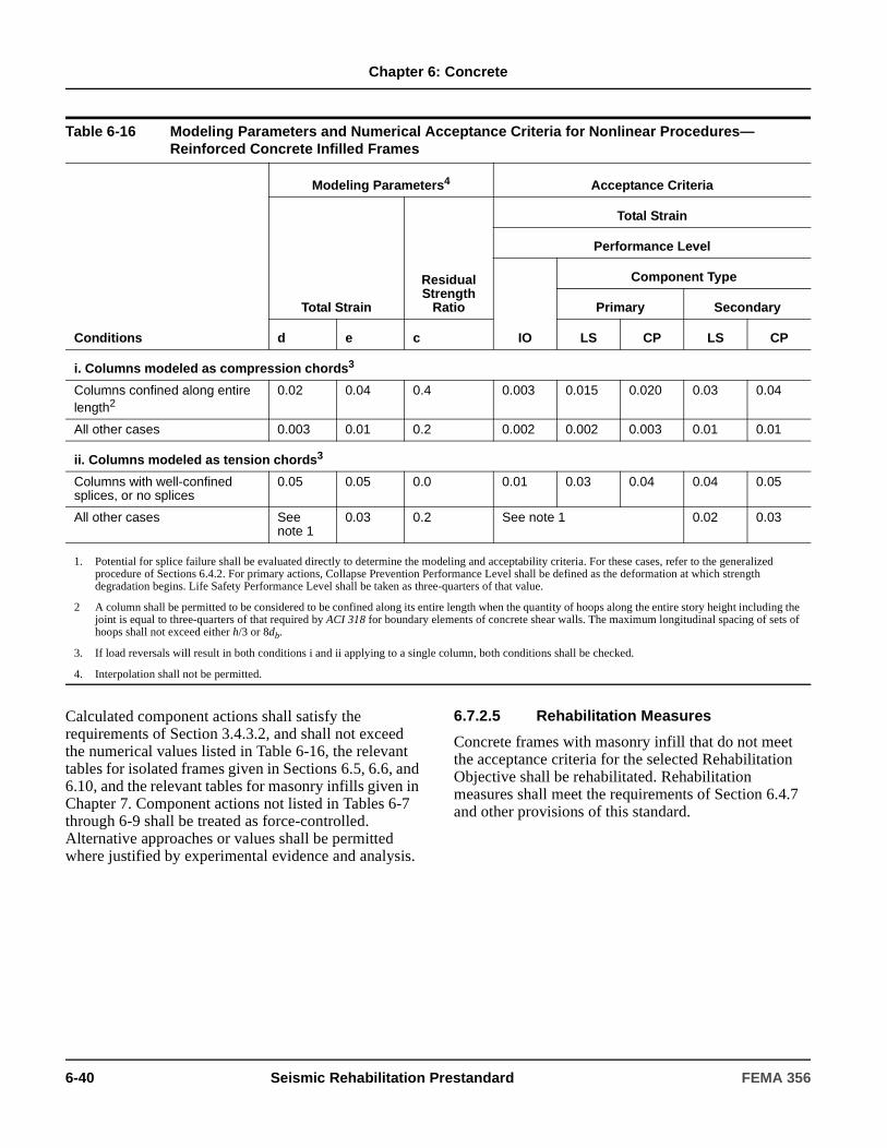
Chapter 6: Concrete
Calculated component actions shall satisfy the requirements of Section 3.4.3.2, and shall not exceed the numerical values listed in Table 6-16, the relevant tables for isolated frames given in Sections 6.5, 6.6, and 6.10, and the relevant tables for masonry infills given in Chapter 7. Component actions not listed in Tables 6-7 through 6-9 shall be treated as force-controlled. Alternative approaches or values shall be permitted where justified by experimental evidence and analysis.
6.7.2.5 Rehabilitation Measures
Concrete frames with masonry infill that do not meet the acceptance criteria for the selected Rehabilitation Objective shall be rehabilitated. Rehabilitation measures shall meet the requirements of Section 6.4.7 and other provisions of this standard.
Table 6-16 Modeling Parameters and Numerical Acceptance Criteria for Nonlinear Procedures—Reinforced Concrete Infilled Frames
Conditions
Modeling Parameters4 Acceptance Criteria
Total Strain
Residual Strength
Ratio
Total Strain
Performance Level
IO
Component Type
Primary Secondary
d e c LS CP LS CP
i. Columns modeled as compression chords3
Columns confined along entire length2
0.02 0.04 0.4 0.003 0.015 0.020 0.03 0.04
All other cases 0.003 0.01 0.2 0.002 0.002 0.003 0.01 0.01
ii. Columns modeled as tension chords3
Columns with well-confined splices, or no splices
0.05 0.05 0.0 0.01 0.03 0.04 0.04 0.05
All other cases See note 1
0.03 0.2 See note 1 0.02 0.03
1. Potential for splice failure shall be evaluated directly to determine the modeling and acceptability criteria. For these cases, refer to the generalized procedure of Sections 6.4.2. For primary actions, Collapse Prevention Performance Level shall be defined as the deformation at which strength degradation begins. Life Safety Performance Level shall be taken as three-quarters of that value.
2 A column shall be permitted to be considered to be confined along its entire length when the quantity of hoops along the entire story height including the joint is equal to three-quarters of that required by ACI 318 for boundary elements of concrete shear walls. The maximum longitudinal spacing of sets of hoops shall not exceed either h/3 or 8db.
3. If load reversals will result in both conditions i and ii applying to a single column, both conditions shall be checked.
4. Interpolation shall not be permitted.
6-40 Seismic Rehabilitation Prestandard FEMA 356
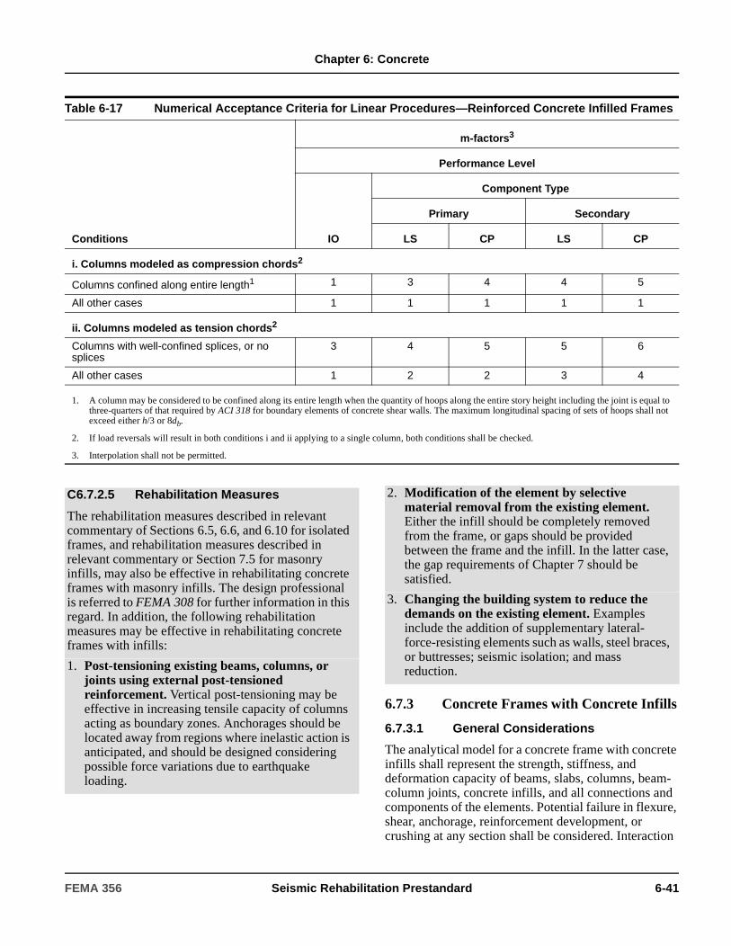
Chapter 6: Concrete
6.7.3 Concrete Frames with Concrete Infills
6.7.3.1 General Considerations
The analytical model for a concrete frame with concrete infills shall represent the strength, stiffness, and deformation capacity of beams, slabs, columns, beam-column joints, concrete infills, and all connections and components of the elements. Potential failure in flexure, shear, anchorage, reinforcement development, or crushing at any section shall be considered. Interaction
Table 6-17 Numerical Acceptance Criteria for Linear Procedures—Reinforced Concrete Infilled Frames
Conditions
m-factors3
Performance Level
IO
Component Type
Primary Secondary
LS CP LS CP
i. Columns modeled as compression chords2
Columns confined along entire length1 1 3 4 4 5
All other cases 1 1 1 1 1
ii. Columns modeled as tension chords2
Columns with well-confined splices, or no splices
3 4 5 5 6
All other cases 1 2 2 3 4
1. A column may be considered to be confined along its entire length when the quantity of hoops along the entire story height including the joint is equal to three-quarters of that required by ACI 318 for boundary elements of concrete shear walls. The maximum longitudinal spacing of sets of hoops shall not exceed either h/3 or 8db.
2. If load reversals will result in both conditions i and ii applying to a single column, both conditions shall be checked.
3. Interpolation shall not be permitted.
C6.7.2.5 Rehabilitation Measures
The rehabilitation measures described in relevant commentary of Sections 6.5, 6.6, and 6.10 for isolated frames, and rehabilitation measures described in relevant commentary or Section 7.5 for masonry infills, may also be effective in rehabilitating concrete frames with masonry infills. The design professional is referred to FEMA 308 for further information in this regard. In addition, the following rehabilitation measures may be effective in rehabilitating concrete frames with infills:
1. Post-tensioning existing beams, columns, or joints using external post-tensioned reinforcement. Vertical post-tensioning may be effective in increasing tensile capacity of columns acting as boundary zones. Anchorages should be located away from regions where inelastic action is anticipated, and should be designed considering possible force variations due to earthquake loading.
2. Modification of the element by selective material removal from the existing element. Either the infill should be completely removed from the frame, or gaps should be provided between the frame and the infill. In the latter case, the gap requirements of Chapter 7 should be satisfied.
3. Changing the building system to reduce the demands on the existing element. Examples include the addition of supplementary lateral-force-resisting elements such as walls, steel braces, or buttresses; seismic isolation; and mass reduction.
FEMA 356 Seismic Rehabilitation Prestandard 6-41

Chapter 6: Concrete
with other nonstructural elements and components shall be included.
The analytical model shall be established considering the relative stiffness and strength of the frame and the infill, as well as the level of deformations and associated damage. For low deformation levels, and for cases where the frame is relatively flexible, the infilled frame shall be permitted to be modeled as a shear wall, with openings modeled where they occur. In other cases, the frame-infill system shall be permitted to be modeled using a braced-frame analogy such as that described for concrete frames with masonry infills in Section 6.7.2.
Frame components shall be evaluated for forces imparted to them through interaction of the frame with the infill as specified in Chapter 7. In frames with full-height infills, the evaluation shall include the effect of strut compression forces applied to the column and beam eccentric from the beam-column joint. In frames with partial-height infills, the evaluation shall include the reduced effective length of the columns above the infilled portion of the bay.
In frames having infills in some bays and no infills in other bays, the restraint of the infill shall be represented as described in this section, and the noninfilled bays shall be modeled as frames as specified in appropriate portions of Sections 6.5, 6.6, and 6.10. Where infills create a discontinuous wall, the effects of the discontinuity on overall building performance shall be evaluated.
6.7.3.2 Stiffness
6.7.3.2.1 Linear Static and Dynamic Procedures
Effective stiffnesses shall be calculated according to the principles of Section 6.4.1.2 and the procedure of Section 6.7.2.2.1.
6.7.3.2.2 Nonlinear Static Procedure
Nonlinear load-deformation relations for use in analysis by Nonlinear Static Procedure (NSP) shall follow the requirements of Section 6.4.1.2.2.
Monotonic load-deformation relations shall be according to the generalized relation shown in Figure 6-1, except different relations shall be permitted where verified by tests. Numerical quantities in Figure 6-1 shall be derived from tests or by analysis procedures
specified in Section 2.8, and shall take into account the interactions between frame and infill components. Alternatively, the procedure of Section 6.7.2.2.2 shall be permitted for the development of nonlinear modeling parameters for concrete frames with concrete infills.
6.7.3.2.3 Nonlinear Dynamic Procedure
Nonlinear load-deformation relations for use in analysis by Nonlinear Dynamic Procedure (NDP) shall model the complete hysteretic behavior of each component using properties verified by tests. Unloading and reloading properties shall represent stiffness and strength degradation characteristics.
6.7.3.3 Strength
Strengths of reinforced concrete components shall be calculated according to the general requirements of Sections 6.4.2, as modified by other specifications of this chapter. Strength calculations shall consider:
1. Limitations imposed by beams, columns, and joints in unfilled portions of frames.
2. Tensile and compressive capacity of columns acting as boundary elements of infilled frames.
3. Local forces applied from the infill to the frame.
4. Strength of the infill.
5. Connections with adjacent elements.
Strengths of existing concrete infills shall be determined considering shear strength of the infill panel. For this calculation, procedures specified in Section 6.8.2.3 shall be used for calculation of the shear strength of a wall segment.
Where the frame and concrete infill are assumed to act as a monolithic wall, flexural strength shall be based on continuity of vertical reinforcement in both (1) the columns acting as boundary elements, and (2) the infill wall, including anchorage of the infill reinforcement in the boundary frame.
6.7.3.4 Acceptance Criteria
The acceptance criteria for concrete frames with concrete infills shall comply with relevant acceptance criteria of Sections 6.7.2.4, 6.8, and 6.9.
6-42 Seismic Rehabilitation Prestandard FEMA 356
Chapter 6: Concrete
6.7.3.5 Rehabilitation Measures
Concrete frames with concrete infills that do not meet the acceptance criteria for the selected Rehabilitation Objective shall be rehabilitated. Rehabilitation measures shall meet the requirements of Section 6.4.7 and other provisions of this standard.
6.8 Concrete Shear Walls
6.8.1 Types of Concrete Shear Walls and Associated Components
The provisions of Section 6.8 shall apply to all shear walls in all types of structural systems that incorporate shear walls. This includes isolated shear walls, shear walls used in dual (wall-frame) systems, coupled shear walls, and discontinuous shear walls. Shear walls shall be permitted to be considered as solid walls if they have openings that do not significantly influence the strength or inelastic behavior of the wall. Perforated shear walls shall be defined as walls having a regular pattern of
openings in both horizontal and vertical directions that creates a series of pier and deep beam elements referred to as wall segments.
Coupling beams, and columns that support discontinuous shear walls, shall comply with provisions of Section 6.8.2. These special frame components associated with shear walls shall be exempted from the provisions for beams and columns of frame elements covered in Section 6.5.
C6.7.3.5 Rehabilitation Measures
Rehabilitation measures described in C6.7.2.5 for concrete frames with masonry infills may also be effective in rehabilitating concrete frames with concrete infills. In addition, application of shotcrete to the face of an existing wall to increase the thickness and shear strength may be effective. For this purpose, the face of the existing wall should be roughened, a mat of reinforcing steel should be doweled into the existing structure, and shotcrete should be applied to the desired thickness. The design professional is referred to FEMA 308 for further information regarding rehabilitation of concrete frames with concrete infill.
C6.8.1 Types of Concrete Shear Walls and Associated Components
Concrete shear walls are planar vertical elements or combinations of interconnected planar elements that serve as lateral-load-resisting elements in concrete structures. Shear walls (or wall segments) shall be considered slender if their aspect ratio (height/length) is >3.0, and shall be considered short or squat if their aspect ration is <1.5. Slender shear walls are normally controlled by flexural behavior; short walls are normally controlled by shear behavior. The response of walls with intermediate aspect ratios is influenced by both flexure and shear.
Identification of component types in concrete shear wall elements depends, to some degree, on the relative strengths of the wall segments. Vertical segments are often termed piers, while horizontal segments may be called coupling beams or spandrels. The design professional is referred to FEMA 306 for additional information regarding the behavior of concrete wall components. Selected information from FEMA 306 has been reproduced in the commentary of this standard, in Table C6-1 and Figure C6-1 to clarify wall component identification.
FEMA 356 Seismic Rehabilitation Prestandard 6-43

Chapter 6: Concrete
Figure C6-1 Identification of Component Types in Concrete Shear Wall Elements (from FEMA 306)
6-44 Seismic Rehabilitation Prestandard FEMA 356

Chapter 6: Concrete
6.8.1.1 Monolithic Reinforced Concrete Shear Walls and Wall Segments
Monolithic reinforced concrete shear walls shall consist of vertical cast-in-place elements, either uncoupled or coupled, in open or closed shapes. These walls shall have relatively continuous cross sections and reinforcement and shall provide both vertical and lateral force resistance, in contrast with infilled walls defined in Section 6.7.1.3.
Shear walls or wall segments with axial loads greater than 0.35 Po shall not be considered effective in resisting seismic forces. The maximum spacing of horizontal and vertical reinforcement shall not exceed 18 inches. Walls with horizontal and vertical reinforcement ratios less than 0.0025, but with reinforcement spacings less than 18 inches, shall be permitted where the shear force demand does not exceed the reduced nominal shear strength of the wall calculated in accordance with Section 6.8.2.3.
Table C6-1 Reinforced Concrete Shear Wall Component Types (from FEMA 306)
Component Typeper FEMA 306 Description FEMA 356 Designation
RC1 Isolated Wall or Stronger Wall Pier
Stronger than beam or spandrel elements that may frame into it so that nonlinear behavior (and damage) is generally concentrated at the base, with a flexural plastic hinge, shear failure, etc. Includes isolated (cantilever) walls. If the component has a major setback or cutoff of reinforcement above the base, this section should be also checked for nonlinear behavior
Monolithic reinforced concrete wall or vertical wall segment
RC2 Weaker Wall Pier Weaker than the spandrels to which it connects; characterized by flexural hinging top and bottom, or shear failure, etc.
RC3 Weaker Spandrel or Coupling Beam
Weaker than the wall piers to which it connects; characterized by hinging at each end, shear failure, sliding shear failure, etc.
Horizontal wall segment or coupling beam
RC4 Stronger Spandrel Should not suffer damage because it is stronger than attached piers. If this component is damaged, it should probably be re-classified as RC3.
RC5 Pier-Spandrel Panel Zone
Typically not a critical area in RC walls Wall segment
C6.8.1.1 Monolithic Reinforced Concrete Shear Walls and Wall Segments
The wall reinforcement is normally continuous in both the horizontal and vertical directions, and bars are typically lap-spliced for tension continuity. The reinforcement mesh may also contain horizontal ties around vertical bars that are concentrated either near the vertical edges of a wall with constant thickness, or in boundary members formed at the wall edges. The amount and spacing of these ties is important for determining how well the concrete at the wall edge is confined, and thus for determining the lateral deformation capacity of the wall.
FEMA 356 Seismic Rehabilitation Prestandard 6-45

Chapter 6: Concrete
6.8.1.2 Reinforced Concrete Columns Supporting Discontinuous Shear Walls
Reinforced concrete columns supporting discontinuous shear walls shall be evaluated and rehabilitated to comply with the requirements of Section 6.8.2.
6.8.1.3 Reinforced Concrete Coupling Beams
Reinforced concrete coupling beams used to link two shear walls together shall be evaluated and rehabilitated to comply with the requirements of Section 6.8.2.
6.8.2 Reinforced Concrete Shear Walls, Wall Segments, Coupling Beams, and RC Columns Supporting Discontinuous Shear Walls
6.8.2.1 General Considerations
The analytical model for a shear wall element shall represent the stiffness, strength, and deformation capacity of the shear wall. Potential failure in flexure, shear, and reinforcement development at any point in the shear wall shall be considered. Interaction with other structural and nonstructural elements shall be included.
In general, slender reinforced concrete shear walls will be governed by flexure and will tend to form a plastic flexural hinge near the base of the wall under severe lateral loading. The ductility of the wall will be a function of the percentage of longitudinal reinforcement concentrated near the boundaries of the wall, the level of axial load, the amount of lateral shear required to cause flexural yielding, and the thickness and reinforcement used in the web portion of the shear wall. In general, higher axial load stresses and higher shear stresses will reduce the flexural ductility and energy absorbing capability of the shear wall. Short or squat shear walls will normally be governed by shear. These walls will normally have a limited ability to deform beyond the elastic range and continue to carry lateral loads. Thus, these walls are typically designed either as displacement-controlled components with low ductility capacities or as force-controlled components.
C6.8.1.2 Reinforced Concrete Columns Supporting Discontinuous Shear Walls
In shear wall buildings it is not uncommon to find that some walls are terminated either to create commercial space in the first story or to create parking spaces in the basement. In such cases, the walls are commonly supported by columns. Such designs are not recommended in seismic zones because very large demands may be placed on these columns during earthquake loading. In older buildings such columns will often have “standard” longitudinal and transverse reinforcement; the behavior of such columns during past earthquakes indicates that tightly spaced closed ties with well-anchored 135-degree hooks will be required for the building to survive severe earthquake loading.
C6.8.1.3 Reinforced Concrete Coupling Beams
The coupled walls are generally much stiffer and stronger than they would be if they acted independently. Coupling beams typically have a small span-to-depth ratio, and their inelastic behavior is normally affected by the high shear forces acting in these components. Coupling beams in most older reinforced concrete buildings will commonly have “conventional” reinforcement that consists of longitudinal flexural steel and transverse steel for shear. In some, more modern buildings, or in buildings where coupled shear walls are used for seismic rehabilitation, the coupling beams may use diagonal reinforcement as the primary reinforcement for both flexure and shear. The inelastic behavior of coupling beams that use diagonal reinforcement has been shown experimentally to be much better with respect to retention of strength, stiffness, and energy dissipation capacity than the observed behavior of coupling beams with conventional reinforcement.
6-46 Seismic Rehabilitation Prestandard FEMA 356
Chapter 6: Concrete
Slender shear walls and wall segments shall be permitted to be modeled as equivalent beam-column elements that include both flexural and shear deformations. The flexural strength of beam-column elements shall include the interaction of axial load and bending. The rigid-connection zone at beam connections to this equivalent beam-column element shall represent the distance from the wall centroid to the edge of the wall. Unsymmetrical wall sections shall model the different bending capacities for the two loading directions.
A beam element that incorporates both bending and shear deformations shall be used to model coupling beams. The element inelastic response shall account for the loss of shear strength and stiffness during reversed cyclic loading to large deformations. For coupling beams that have diagonal reinforcement satisfying ACI 318, a beam element representing flexure only shall be permitted.
For columns supporting discontinuous shear walls, the model shall account for axial compression, axial tension, flexure, and shear response including rapid loss of resistance where this behavior is likely under design loadings. The diaphragm action of concrete slabs that interconnect shear walls and frame columns shall be represented in the model.
6.8.2.2 Stiffness
The effective stiffness of all the elements discussed in Section 6.8 shall be defined based on the material properties, component dimensions, reinforcement quantities, boundary conditions, and current state of the member with respect to cracking and stress levels. Alternatively, use of values for effective stiffness given in Table 6-5 shall be permitted. To obtain a proper distribution of lateral forces in bearing wall buildings, all of the walls shall be assumed to be either cracked or uncracked. In buildings where lateral load resistance is provided by either structural walls only, or a combination of walls and frame members, all shear walls and wall segments discussed in this section shall be considered to be cracked.
For coupling beams, the effective stiffness values given in Table 6-5 for nonprestressed beams shall be used unless alternative stiffnesses are determined by more detailed analysis. The effective stiffness of columns supporting discontinuous shear walls shall change between the values given for columns in tension and compression, depending on the direction of the lateral load being resisted by the shear wall.
6.8.2.2.1 Linear Static and Dynamic Procedures
Shear walls and associated components shall be modeled considering axial, flexural, and shear stiffness. For closed and open wall shapes, such as box, T, L, I, and C sections, the effective tension or compression flange widths shall be as specified in Section 6.4.1.3. The calculated stiffnesses to be used in analysis shall be in accordance with the requirements of Section 6.4.1.2.
Joints between shear walls and frame elements shall be modeled as stiff components or rigid components, as appropriate.
6.8.2.2.2 Nonlinear Static Procedure
Nonlinear load-deformation relations for use in analysis by nonlinear static and dynamic procedures shall comply with the requirements of Section 6.4.1.2.
Monotonic load-deformation relationships for analytical models that represent shear walls, wall elements, coupling beams, and columns that support discontinuous shear walls shall be in accordance with the generalized relation shown in Figure 6-1.
C6.8.2.1 General Considerations
For rectangular shear walls and wall segments with , and flanged wall sections with
, either a modified beam-column analogy or a multiple-node, multiple-spring approach should be used. Because shear walls usually respond in single curvature over a story height, the use of one multiple-spring element per story should be permitted for modeling shear walls. Wall segments should be modeled with either the beam-column element or with a multiple-spring model with two elements over the length of the wall segment.
Coupling beams that have diagonal reinforcement satisfying FEMA 222A will commonly have a stable hysteretic response under large load reversals. Therefore, these members could adequately be modeled with beam elements used for typical frame analyses.
hw lw 2.5≤⁄
hw lw 3.5≤⁄
FEMA 356 Seismic Rehabilitation Prestandard 6-47
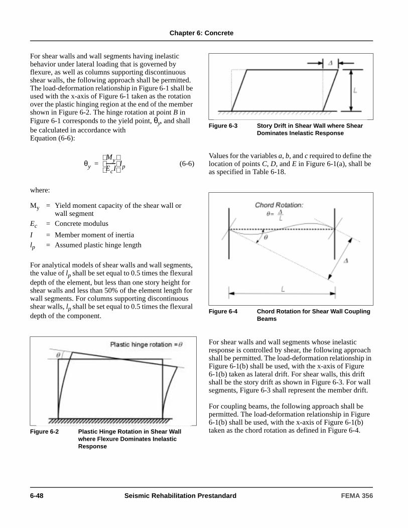
Chapter 6: Concrete
For shear walls and wall segments having inelastic behavior under lateral loading that is governed by flexure, as well as columns supporting discontinuous shear walls, the following approach shall be permitted. The load-deformation relationship in Figure 6-1 shall be used with the x-axis of Figure 6-1 taken as the rotation over the plastic hinging region at the end of the member shown in Figure 6-2. The hinge rotation at point B in Figure 6-1 corresponds to the yield point, θy, and shall be calculated in accordance with Equation (6-6):
(6-6)
where:
For analytical models of shear walls and wall segments, the value of lp shall be set equal to 0.5 times the flexural depth of the element, but less than one story height for shear walls and less than 50% of the element length for wall segments. For columns supporting discontinuous shear walls, lp shall be set equal to 0.5 times the flexural depth of the component.
Values for the variables a, b, and c required to define the location of points C, D, and E in Figure 6-1(a), shall be as specified in Table 6-18.
For shear walls and wall segments whose inelastic response is controlled by shear, the following approach shall be permitted. The load-deformation relationship in Figure 6-1(b) shall be used, with the x-axis of Figure 6-1(b) taken as lateral drift. For shear walls, this drift shall be the story drift as shown in Figure 6-3. For wall segments, Figure 6-3 shall represent the member drift.
For coupling beams, the following approach shall be permitted. The load-deformation relationship in Figure 6-1(b) shall be used, with the x-axis of Figure 6-1(b) taken as the chord rotation as defined in Figure 6-4.
My = Yield moment capacity of the shear wall or wall segment
Ec = Concrete modulus
I = Member moment of inertialp = Assumed plastic hinge length
Figure 6-2 Plastic Hinge Rotation in Shear Wall where Flexure Dominates Inelastic Response
θy
My
EcI--------
lp=
Figure 6-3 Story Drift in Shear Wall where Shear Dominates Inelastic Response
Figure 6-4 Chord Rotation for Shear Wall Coupling Beams
6-48 Seismic Rehabilitation Prestandard FEMA 356
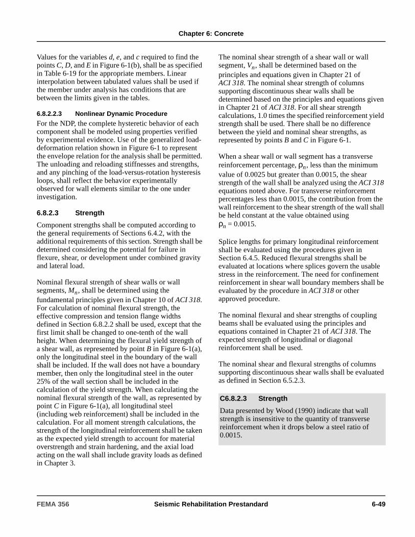
Chapter 6: Concrete
Values for the variables d, e, and c required to find the points C, D, and E in Figure 6-1(b), shall be as specified in Table 6-19 for the appropriate members. Linear interpolation between tabulated values shall be used if the member under analysis has conditions that are between the limits given in the tables.
6.8.2.2.3 Nonlinear Dynamic Procedure
For the NDP, the complete hysteretic behavior of each component shall be modeled using properties verified by experimental evidence. Use of the generalized load-deformation relation shown in Figure 6-1 to represent the envelope relation for the analysis shall be permitted. The unloading and reloading stiffnesses and strengths, and any pinching of the load-versus-rotation hysteresis loops, shall reflect the behavior experimentally observed for wall elements similar to the one under investigation.
6.8.2.3 Strength
Component strengths shall be computed according to the general requirements of Sections 6.4.2, with the additional requirements of this section. Strength shall be determined considering the potential for failure in flexure, shear, or development under combined gravity and lateral load.
Nominal flexural strength of shear walls or wall segments, Mn, shall be determined using the fundamental principles given in Chapter 10 of ACI 318. For calculation of nominal flexural strength, the effective compression and tension flange widths defined in Section 6.8.2.2 shall be used, except that the first limit shall be changed to one-tenth of the wall height. When determining the flexural yield strength of a shear wall, as represented by point B in Figure 6-1(a), only the longitudinal steel in the boundary of the wall shall be included. If the wall does not have a boundary member, then only the longitudinal steel in the outer 25% of the wall section shall be included in the calculation of the yield strength. When calculating the nominal flexural strength of the wall, as represented by point C in Figure 6-1(a), all longitudinal steel (including web reinforcement) shall be included in the calculation. For all moment strength calculations, the strength of the longitudinal reinforcement shall be taken as the expected yield strength to account for material overstrength and strain hardening, and the axial load acting on the wall shall include gravity loads as defined in Chapter 3.
The nominal shear strength of a shear wall or wall segment, Vn, shall be determined based on the principles and equations given in Chapter 21 of ACI 318. The nominal shear strength of columns supporting discontinuous shear walls shall be determined based on the principles and equations given in Chapter 21 of ACI 318. For all shear strength calculations, 1.0 times the specified reinforcement yield strength shall be used. There shall be no difference between the yield and nominal shear strengths, as represented by points B and C in Figure 6-1.
When a shear wall or wall segment has a transverse reinforcement percentage, ρn, less than the minimum value of 0.0025 but greater than 0.0015, the shear strength of the wall shall be analyzed using the ACI 318 equations noted above. For transverse reinforcement percentages less than 0.0015, the contribution from the wall reinforcement to the shear strength of the wall shall be held constant at the value obtained using ρn = 0.0015.
Splice lengths for primary longitudinal reinforcement shall be evaluated using the procedures given in Section 6.4.5. Reduced flexural strengths shall be evaluated at locations where splices govern the usable stress in the reinforcement. The need for confinement reinforcement in shear wall boundary members shall be evaluated by the procedure in ACI 318 or other approved procedure.
The nominal flexural and shear strengths of coupling beams shall be evaluated using the principles and equations contained in Chapter 21 of ACI 318. The expected strength of longitudinal or diagonal reinforcement shall be used.
The nominal shear and flexural strengths of columns supporting discontinuous shear walls shall be evaluated as defined in Section 6.5.2.3.
C6.8.2.3 Strength
Data presented by Wood (1990) indicate that wall strength is insensitive to the quantity of transverse reinforcement when it drops below a steel ratio of 0.0015.
FEMA 356 Seismic Rehabilitation Prestandard 6-49

Chapter 6: Concrete
6.8.2.4 Acceptance Criteria
6.8.2.4.1 Linear Static and Dynamic Procedures
Shear walls, wall segments, coupling beams, and columns supporting discontinuous shear walls shall be classified as either deformation- or force-controlled, as defined in Section 2.4.4. For columns supporting discontinuous shear walls, deformation-controlled actions shall be restricted to flexure. In other components, deformation-controlled actions shall be restricted to flexure or shear. All other actions shall be defined as being force-controlled actions.
The nominal flexural strength of a shear wall or wall segment shall be used to determine the maximum shear force in shear walls, wall segments, and columns supporting discontinuous shear walls. For cantilever shear walls and columns supporting discontinuous shear walls, the design shear force shall be equal to the magnitude of the lateral force required to develop the nominal flexural strength at the base of the wall, assuming the lateral force is distributed uniformly over the height of the wall. For wall segments, the design force shall be equal to the shear corresponding to the development of the positive and negative nominal moment strengths at opposite ends of the wall segment.
Design actions (flexure, shear, or force transfer at rebar anchorages and splices) on components shall be determined as prescribed in Chapter 3. When determining the appropriate value for the design actions, proper consideration shall be given to gravity loads and to the maximum forces that can be transmitted considering nonlinear action in adjacent components. Design actions shall be compared with design strengths in accordance with Section 3.4.2.2. Table 6-20 and 6-21 specify m values for use in Equation (3-20). Alternate m values shall be permitted where justified by experimental evidence and analysis.
6.8.2.4.2 Nonlinear Static and Dynamic Procedures
In the design model, inelastic response shall be restricted to those elements and actions listed in Tables 6-18 and 6-19, except where it is demonstrated that other inelastic actions are justified for the selected performance levels. For members experiencing inelastic behavior, the magnitude of other actions (forces, moments, or torque) in the member shall correspond to the magnitude of the action causing inelastic behavior. The magnitude of these other actions shall be shown to be below their nominal capacities.
Components experiencing inelastic response shall satisfy the requirements of Section 3.4.3.2, and the maximum plastic hinge rotations, drifts, or chord rotation angles shall not exceed the values given in Tables 6-18 and 6-19, for the selected performance level. Linear interpolation between tabulated values shall be used if the member under analysis has conditions that are between the limits given in the tables.
The need for confinement reinforcement in shear wall boundary members may be evaluated by the method recommended by Wallace (1994 and 1995) for determining maximum lateral deformations in the wall and the resulting maximum compression strains in the wall boundary.
6-50 Seismic Rehabilitation Prestandard FEMA 356

Chapter 6: Concrete
Table 6-18 Modeling Parameters and Numerical Acceptance Criteria for Nonlinear Procedures—Members Controlled by Flexure
Conditions
Plastic Hinge Rotation(radians)
ResidualStrength
Ratio
Acceptable Plastic Hinge Rotation(radians)
Performance Level
IO
Component Type
Primary Secondary4
a b c LS CP LS CP
i. Shear walls and wall segments
Confined Boundary1
≤ 0.1 ≤3 Yes 0.015 0.020 0.75 0.005 0.010 0.015 0.015 0.020
≤ 0.1 ≥ 6 Yes 0.010 0.015 0.40 0.004 0.008 0.010 0.010 0.015
≥ 0.25 ≤ 3 Yes 0.009 0.012 0.60 0.003 0.006 0.009 0.009 0.012
≥ 0.25 ≥ 6 Yes 0.005 0.010 0.30 0.0015 0.003 0.005 0.005 0.010
≤ 0.1 ≤ 3 No 0.008 0.015 0.60 0.002 0.004 0.008 0.008 0.015
≤ 0.1 ≥ 6 No 0.006 0.010 0.30 0.002 0.004 0.006 0.006 0.010
≥ 0.25 ≤ 3 No 0.003 0.005 0.25 0.001 0.002 0.003 0.003 0.005
≥ 0.25 ≥ 6 No 0.002 0.004 0.20 0.001 0.001 0.002 0.002 0.004
ii. Columns supporting discontinuous shear walls
Transverse reinforcement2
Conforming 0.010 0.015 0.20 0.003 0.007 0.010 n.a. n.a.
Nonconforming 0.0 0.0 0.0 0.0 0.0 0.0 n.a. n.a.
iii. Shear wall coupling beams
Longitudinal reinforcement and transverse reinforcement3
Conventional longitudinal reinforcement with conforming transverse reinforcement
≤ 3 0.025 0.050 0.75 0.010 0.02 0.025 0.025 0.050
≥ 6 0.02 0.040 0.50 0.005 0.010 0.020 0.020 0.040
Conventional longitudinal reinforcement with nonconforming transverse reinforcement
≤ 3 0.020 0.035 0.50 0.006 0.012 0.020 0.020 0.035
≥ 6 0.010 0.025 0.25 0.005 0.008 0.010 0.010 0.025
Diagonal reinforcement n.a. 0.030 0.050 0.80 0.006 0.018 0.030 0.030 0.050
1. Requirements for a confined boundary are the same as those given in ACI 318.
2. Requirements for conforming transverse reinforcement in columns are: (a) hoops over the entire length of the column at a spacing ≤ d/2, and (b) strength of hoops Vs ≥ required shear strength of column.
3. Conventional longitudinal reinforcement consists of top and bottom steel parallel to the longitudinal axis of the coupling beam. Conforming transverse reinforcement consists of: (a) closed stirrups over the entire length of the coupling beam at a spacing ≤ d/3, and (b) strength of closed stirrups Vs ≥ 3/4 of required shear strength of the coupling beam.
4. For secondary coupling beams spanning <8’-0”, with bottom reinforcement continuous into the supporting walls, secondary values shall be permitted to be doubled.
As As– ′( )fy P+
twlwfc′------------------------------------
Shear
twlw fc ′---------------------
Shear
twlw fc ′---------------------
FEMA 356 Seismic Rehabilitation Prestandard 6-51

Chapter 6: Concrete
Table 6-19 Modeling Parameters and Numerical Acceptance Criteria for Nonlinear Procedures—Members Controlled by Shear
Conditions
Total Drift Ratio (%), or Chord
Rotation (radians)1
Residual Strength
Ratio
Acceptable Total Drift (%) or Chord Rotation (radians)1
Performance Level
IO
Component Type
Primary Secondary
d e c LS CP LS CP
i. Shear walls and wall segments
All shear walls and wall segments2 0.75 2.0 0.40 0.40 0.60 0.75 0.75 1.5
ii. Shear wall coupling beams4
Longitudinal reinforcement and transverse reinforcement3
Conventional longitudinal reinforcement with conforming transverse reinforcement
≤ 3 0.002 0.030 0.600.006 0.015 0.020 0.020 0.030
≥ 6 0.016 0.024 0.300.005 0.012 0.016 0.016 0.024
Conventional longitudinal reinforcement with nonconforming transverse reinforcement
≤ 3 0.012 0.025 0.400.006 0.008 0.010 0.010 0.020
≥ 6 0.008 0.014 0.200.004 0.006 0.007 0.007 0.012
1. For shear walls and wall segments, use drift; for coupling beams, use chord rotation; refer to Figures 6-3 and 6-4.
2. For shear walls and wall segments where inelastic behavior is governed by shear, the axial load on the member must be ≤ 0.15 Ag fc’; otherwise, the member must be treated as a force-controlled component.
3. Conventional longitudinal reinforcement consists of top and bottom steel parallel to the longitudinal axis of the coupling beam. Conforming transverse reinforcement consists of: (a) closed stirrups over the entire length of the coupling beam at a spacing ≤ d/3, and (b) strength of closed stirrups Vs ≥ 3/4 of required shear strength of the coupling beam.
4. For secondary coupling beams spanning <8’-0”, with bottom reinforcement continuous into the supporting walls, secondary values shall be permitted to be doubled.
Shear
twlw fc′---------------------
6-52 Seismic Rehabilitation Prestandard FEMA 356

Chapter 6: Concrete
Table 6-20 Numerical Acceptance Criteria for Linear Procedures—Members Controlled by Flexure
Conditions
m-factors
Performance Level
IO
Component Type
Primary Secondary
LS CP LS CP
i. Shear walls and wall segments
5Confined
Boundary1
≤ 0.1 ≤ 3 Yes 2 4 6 6 8
≤ 0.1 ≥ 6 Yes 2 3 4 4 6
≥ 0.25 ≤ 3 Yes 1.5 3 4 4 6
≥ 0.25 ≥ 6 Yes 1.25 2 2.5 2.5 4
≤ 0.1 ≤ 3 No 2 2.5 4 4 6
≤ 0.1 ≥ 6 No 1.5 2 2.5 2.5 4
≥ 0.25 ≤ 3 No 1.25 1.5 2 2 3
≥ 0.25 ≥ 6 No 1.25 1.5 1.75 1.75 2
ii. Columns supporting discontinuous shear walls
Transverse reinforcement2
Conforming 1 1.5 2 n.a. n.a.
Nonconforming 1 1 1 n.a. n.a.
iii. Shear wall coupling beams4
Longitudinal reinforcement and transverse reinforcement3
5
Conventional longitudinal reinforcement with conforming transverse reinforcement
≤ 3 2 4 6 6 9
≥ 6 1.5 3 4 4 7
Conventional longitudinal reinforcement with nonconforming transverse reinforcement
≤ 3 1.5 3.5 5 5 8
≥ 6 1.2 1.8 2.5 2.5 4
Diagonal reinforcement n.a. 2 5 7 7 10
1. Requirements for a confined boundary are the same as those given in ACI 318.
2. Requirements for conforming transverse reinforcement in columns are: (a) hoops over the entire length of the column at a spacing ≤ d/2, and (b) strength of hoops Vs ≥ required shear strength of column.
3. Conventional longitudinal reinforcement consists of top and bottom steel parallel to the longitudinal axis of the coupling beam. Conforming transverse reinforcement consists of: (a) closed stirrups over the entire length of the coupling beam at a spacing ≤ d/3, and (b) strength of closed stirrups Vs ≥ 3/4 of required shear strength of the coupling beam.
4. For secondary coupling beams spanning <8’-0”, with bottom reinforcement continuous into the supporting walls, secondary values shall be permitted to be doubled.
5. Design shear shall be calculated using limit-state analysis procedures.
As As– ′( )fy P+
twlwfc′------------------------------------
Shear
twlw fc ′---------------------
Shear
twlw fc ′---------------------
FEMA 356 Seismic Rehabilitation Prestandard 6-53

Chapter 6: Concrete
Table 6-21 Numerical Acceptance Criteria for Linear Procedures—Members Controlled by Shear
Conditions
m-factors
Performance Level
IO
Component Type
Primary Secondary
LS CP LS CP
i. Shear walls and wall segments
All shear walls and wall segments1 2 2 3 2 3
ii. Shear wall coupling beams3
Longitudinal reinforcement and transverse reinforcement2
Conventional longitudinal reinforcement with conforming transverse reinforcement
≤ 3 1.5 3 4 4 6
≥ 6 1.2 2 2.5 2.5 3.5
Conventional longitudinal reinforcement with nonconforming transverse reinforcement
≤ 3 1.5 2.5 3 3 4
≥ 6 1.25 1.2 1.5 1.5 2.5
1. For shear walls and wall segments where inelastic behavior is governed by shear, the axial load on the member must be ≤ 0.15 Ag f ′c, the longitudinal reinforcement must be symmetrical, and the maximum shear demand must be ≤ 6 ; otherwise, the shear shall be considered to be a force-controlled action.
2. Conventional longitudinal reinforcement consists of top and bottom steel parallel to the longitudinal axis of the coupling beam. Conforming transverse reinforcement consists of: (a) closed stirrups over the entire length of the coupling beam at a spacing ≤ d/3, and (b) strength of closed stirrups Vs ≥ 3/4 of required shear strength of the coupling beam.
3. For secondary coupling beams spanning <8’-0”, with bottom reinforcement continuous into the supporting walls, secondary values shall be permitted to be doubled.
Shear
twlw fc′---------------------
fc ′
6-54 Seismic Rehabilitation Prestandard FEMA 356

Chapter 6: Concrete
6.8.2.5 Rehabilitation Measures
Reinforced shear walls, wall segments, coupling beams, and columns supporting discontinuous shear walls that do not meet the acceptance criteria for the selected Rehabilitation Objective shall be rehabilitated. Rehabilitation measures shall meet the requirements of Section 6.4.7 and other provisions of this standard.
C6.8.2.5 Rehabilitation Measures
The following measures may be effective in rehabilitating reinforced shear walls, wall segments, coupling beams, and reinforced concrete columns supporting discontinuous shear walls:
1. Addition of wall boundary members. Addition of boundary members may be an effective measure in strengthening shear walls or wall segments that have insufficient flexural strength. These members may be either cast-in-place reinforced concrete elements or steel sections. In both cases, proper connections should be made between the existing wall and the added members. The shear capacity of the rehabilitated wall should be re-evaluated.
2. Addition of confinement jackets at wall boundaries. Increasing the confinement at the wall boundaries by the addition of a steel or reinforced concrete jacket may be an effective measure in improving the flexural deformation capacity of a shear wall. For both types of jackets, the longitudinal should not be continuous from story to story unless the jacket is also being used to increase the flexural capacity. The minimum thickness for a concrete jacket should be three inches. Carbon fiber wrap should be permitted for improving the confinement of concrete in compression.
3. Reduction of flexural strength. Reduction in the flexural capacity of a shear wall to change the governing failure mode from shear to flexure may be an effective rehabilitation measure. It may be accomplished by saw-cutting a specified number of longitudinal bars near the edges of the shear wall.
4. Increased shear strength of wall. Increasing the shear strength of the web of a shear wall by casting additional reinforced concrete adjacent to the wall web may be an effective rehabilitation measure. The new concrete should be at least four inches thick and should contain horizontal and vertical reinforcement. The new concrete should be properly bonded to the existing web of the shear wall. The use of carbon fiber sheets, epoxied to the concrete surface, should also be permitted to increase the shear capacity of a shear wall.
5. Confinement jackets to improve deformation capacity of coupling beams and columns supporting discontinuous shear walls. The use of confinement jackets specified above as a rehabilitation measure for wall boundaries, and in Section 6.5 for frame elements, may also be effective in increasing both the shear capacity and the deformation capacity of coupling beams and columns supporting discontinuous shear walls.
6. Infilling between columns supporting discontinuous shear walls. Where a discontinuous shear wall is supported on columns that lack either sufficient strength or deformation capacity to satisfy design criteria, making the wall continuous by infilling the opening between these columns may be an effective rehabilitation measure. The infill and existing columns should be designed to satisfy all the requirements for new wall construction, including any strengthening of the existing columns required by adding a concrete or steel jacket for strength and increased confinement. The opening below a discontinuous shear wall should also be permitted to be “infilled” with steel bracing. The bracing members should be sized to satisfy all design requirements and the columns should be strengthened with a steel or a reinforced concrete jacket.
All of the above rehabilitation measures require an evaluation of the wall foundation, diaphragms, and connections between existing structural elements and any elements added for rehabilitation purposes.
FEMA 356 Seismic Rehabilitation Prestandard 6-55

Chapter 6: Concrete
6.9 Precast Concrete Shear Walls
6.9.1 Types of Precast Shear Walls
Precast concrete shear walls shall consist of story-high or half-story-high precast wall segments that are made continuous through the use of either mechanical connectors or reinforcement splicing techniques with or without a cast-in-place connection strip. Connections between precast segments shall be permitted along both the horizontal and vertical edges of a wall segment.
The design of the following types of precast shear walls shall meet the requirements of Section 6.9:
1. Construction that emulates cast-in-place shear wall defined as that construction in which the reinforcement connections are made to be stronger than the adjacent precast panels so that the lateral load response of the precast wall system will be comparable to that for monolithic shear walls.
2. Jointed construction defined as construction in which inelastic action is permitted to occur at the connections between precast panels.
3. Tilt-up construction defined as a special technique for precast wall construction where there are vertical joints between adjacent panels and horizontal joints at the foundation level, and where the roof or floor diaphragm connects with the tilt-up panel.
6.9.1.1 Construction that Emulates Cast-In-Place Shear Wall
For this type of precast wall, the connections between precast wall elements shall be designed and detailed to be stronger than the panels they connect. The shear walls and wall segments of precast walls that emulate cast-in-place construction shall be evaluated by the criteria defined in Section 6.8.
6.9.1.2 Jointed Construction
Shear walls and wall segments of jointed construction type of precast walls shall be evaluated by the criteria defined in Section 6.9.2.
C6.9.1.1 Construction that Emulates Cast-In-Place Shear Wall
When the precast shear wall is subjected to lateral loading, any yielding and inelastic behavior should take place in the panel elements away from the connections. If the reinforcement detailing in the panel is similar to that for cast-in-place shear walls, then the inelastic response of a precast shear wall should be very similar to that for a cast-in-place wall.
Modern building codes permit the use of precast shear wall construction in high seismic zones if it satisfies the criteria for construction that emulates a cast-in-place shear wall.
C6.9.1.2 Jointed Construction
For most older structures that contain precast shear walls, and for some modern construction, inelastic activity can be expected in the connections between precast wall panels during severe lateral loading. Because joints between precast shear walls in older buildings have often exhibited brittle behavior during inelastic load reversals, jointed construction had not been permitted in high seismic zones. Therefore, when evaluating older buildings that contain precast shear walls that are likely to respond as jointed construction, the permissible ductilities and rotation capacities given in Section 6.8 should be reduced.
For some modern structures, precast shear walls have been constructed with special connectors that are detailed to exhibit ductile response and energy absorption characteristics. Many of these connectors are proprietary and only limited experimental evidence concerning their inelastic behavior is available. Although this type of construction is clearly safer than jointed construction in older buildings, the experimental evidence is not sufficient to permit the use of the same ductility and rotation capacities given for cast-in-place construction. Thus, the permissible values given in Section 6.8 should be reduced.
6-56 Seismic Rehabilitation Prestandard FEMA 356

Chapter 6: Concrete
6.9.1.3 Tilt-up Construction
Shear walls and wall segments of tilt-up type of precast walls shall be evaluated by the criteria defined in Section 6.9.2.
6.9.2 Precast Concrete Shear Walls and Wall Segments
6.9.2.1 General Considerations
The analytical model for a precast concrete shear wall or wall segment shall represent the stiffness, strength, and deformation capacity of the overall member, as well as the connections and joints between any precast panel components that compose the wall. Potential failure in flexure, shear, and reinforcement development at any point in the shear wall panels or connections shall be considered. Interaction with other structural and nonstructural elements shall be included.
Modeling of precast concrete shear walls and wall segments within the precast panels as equivalent beam-columns that include both flexural and shear deformations shall be permitted. The rigid-connection zone at beam connections to these equivalent beam-columns shall represent the distance from the wall centroid to the edge of the wall or wall segment. The different bending capacities for the two loading directions of unsymmetrical precast wall sections shall be modeled.
For precast shear walls and wall segments where shear deformations have a more significant effect on behavior than flextural deformation, a multiple spring model shall be used.
The diaphragm action of concrete slabs interconnecting precast shear walls and frame columns shall be represented in the model.
6.9.2.2 Stiffness
The modeling assumptions defined in Section 6.8.2.2 for monolithic concrete shear walls and wall segments shall also be used for precast concrete walls. In addition, the analytical model shall model the axial, shear, and rotational deformations of the connections between the precast components that compose the wall by either softening the model used to represent the precast panels or by adding spring elements between panels.
6.9.2.2.1 Linear Static and Dynamic Procedures
The modeling procedures given in Section 6.8.2.2.1, combined with a procedure for including connection deformations as noted above, shall be used.
6.9.2.2.2 Nonlinear Static Procedure
Nonlinear load-deformation relations shall comply with the requirements of Section 6.4.1.2. The monotonic load-deformation relationships for analytical models that represent precast shear walls and wall elements within precast panels shall be in accordance with the generalized relation shown in Figure 6-1, except that alternative approaches shall be permitted where verified by experiments. Where the relations are according to the Figure 6-1, the following approach shall be permitted.
Values for plastic hinge rotations or drifts at points B, C, and E for the two general shapes shall be as defined below. The strength levels at points B and C shall correspond to the yield strength and nominal strength, as defined in Section 6.8.2.3. The residual strength for the line segment D–E shall be as defined below.
For precast shear walls and wall segments whose inelastic behavior under lateral loading is governed by flexure, the general load-deformation relationship shall be defined as in Figure 6-1(a). For these members, the x-axis of Figure 6-1(a) shall be taken as the rotation over the plastic hinging region at the end of the member as shown in Figure 6-2. If the requirements for construction that emulates cast-in- place shear wall are satisfied, the value of the hinge rotation at point B shall correspond to the yield rotation, θy, and shall be calculated by Equation (6-6). The same expression shall also be used for wall segments within a precast panel if flexure controls the inelastic response of the segment. If the precast wall is of jointed construction and flexure governs the inelastic response of the member, then the value of θy shall be increased to account for rotation in
C6.9.1.3 Tilt-up Construction
Tilt-up construction should be considered to be a special case of jointed construction. The walls for most buildings constructed by the tilt-up method are longer than their height. Shear would usually govern their in-plane design. The major concern for most tilt-up construction is the connection between the tilt-up wall and the roof diaphragm. That connection should be carefully analyzed to be sure the diaphragm forces can be safely transmitted to the precast wall system.
FEMA 356 Seismic Rehabilitation Prestandard 6-57
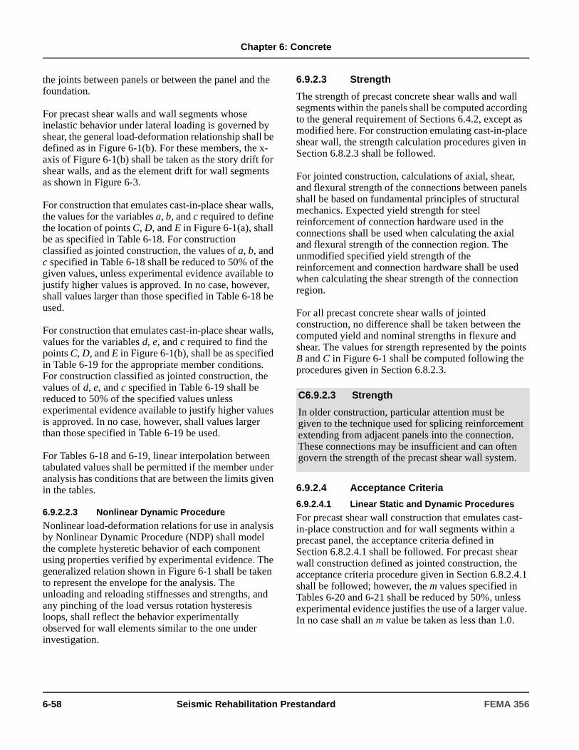
Chapter 6: Concrete
the joints between panels or between the panel and the foundation.
For precast shear walls and wall segments whose inelastic behavior under lateral loading is governed by shear, the general load-deformation relationship shall be defined as in Figure 6-1(b). For these members, the x-axis of Figure 6-1(b) shall be taken as the story drift for shear walls, and as the element drift for wall segments as shown in Figure 6-3.
For construction that emulates cast-in-place shear walls, the values for the variables a, b, and c required to define the location of points C, D, and E in Figure 6-1(a), shall be as specified in Table 6-18. For construction classified as jointed construction, the values of a, b, and c specified in Table 6-18 shall be reduced to 50% of the given values, unless experimental evidence available to justify higher values is approved. In no case, however, shall values larger than those specified in Table 6-18 be used.
For construction that emulates cast-in-place shear walls, values for the variables d, e, and c required to find the points C, D, and E in Figure 6-1(b), shall be as specified in Table 6-19 for the appropriate member conditions. For construction classified as jointed construction, the values of d, e, and c specified in Table 6-19 shall be reduced to 50% of the specified values unless experimental evidence available to justify higher values is approved. In no case, however, shall values larger than those specified in Table 6-19 be used.
For Tables 6-18 and 6-19, linear interpolation between tabulated values shall be permitted if the member under analysis has conditions that are between the limits given in the tables.
6.9.2.2.3 Nonlinear Dynamic Procedure
Nonlinear load-deformation relations for use in analysis by Nonlinear Dynamic Procedure (NDP) shall model the complete hysteretic behavior of each component using properties verified by experimental evidence. The generalized relation shown in Figure 6-1 shall be taken to represent the envelope for the analysis. The unloading and reloading stiffnesses and strengths, and any pinching of the load versus rotation hysteresis loops, shall reflect the behavior experimentally observed for wall elements similar to the one under investigation.
6.9.2.3 Strength
The strength of precast concrete shear walls and wall segments within the panels shall be computed according to the general requirement of Sections 6.4.2, except as modified here. For construction emulating cast-in-place shear wall, the strength calculation procedures given in Section 6.8.2.3 shall be followed.
For jointed construction, calculations of axial, shear, and flexural strength of the connections between panels shall be based on fundamental principles of structural mechanics. Expected yield strength for steel reinforcement of connection hardware used in the connections shall be used when calculating the axial and flexural strength of the connection region. The unmodified specified yield strength of the reinforcement and connection hardware shall be used when calculating the shear strength of the connection region.
For all precast concrete shear walls of jointed construction, no difference shall be taken between the computed yield and nominal strengths in flexure and shear. The values for strength represented by the points B and C in Figure 6-1 shall be computed following the procedures given in Section 6.8.2.3.
6.9.2.4 Acceptance Criteria
6.9.2.4.1 Linear Static and Dynamic Procedures
For precast shear wall construction that emulates cast-in-place construction and for wall segments within a precast panel, the acceptance criteria defined in Section 6.8.2.4.1 shall be followed. For precast shear wall construction defined as jointed construction, the acceptance criteria procedure given in Section 6.8.2.4.1 shall be followed; however, the m values specified in Tables 6-20 and 6-21 shall be reduced by 50%, unless experimental evidence justifies the use of a larger value. In no case shall an m value be taken as less than 1.0.
C6.9.2.3 Strength
In older construction, particular attention must be given to the technique used for splicing reinforcement extending from adjacent panels into the connection. These connections may be insufficient and can often govern the strength of the precast shear wall system.
6-58 Seismic Rehabilitation Prestandard FEMA 356
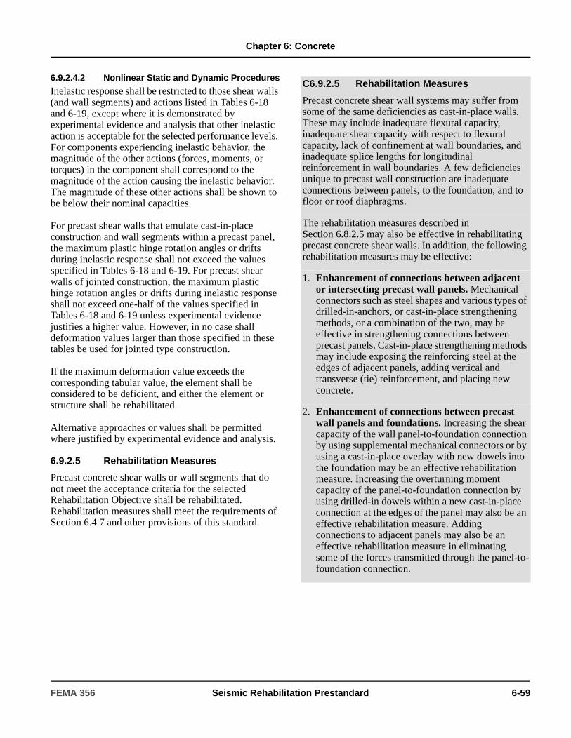
Chapter 6: Concrete
6.9.2.4.2 Nonlinear Static and Dynamic Procedures
Inelastic response shall be restricted to those shear walls (and wall segments) and actions listed in Tables 6-18 and 6-19, except where it is demonstrated by experimental evidence and analysis that other inelastic action is acceptable for the selected performance levels. For components experiencing inelastic behavior, the magnitude of the other actions (forces, moments, or torques) in the component shall correspond to the magnitude of the action causing the inelastic behavior. The magnitude of these other actions shall be shown to be below their nominal capacities.
For precast shear walls that emulate cast-in-place construction and wall segments within a precast panel, the maximum plastic hinge rotation angles or drifts during inelastic response shall not exceed the values specified in Tables 6-18 and 6-19. For precast shear walls of jointed construction, the maximum plastic hinge rotation angles or drifts during inelastic response shall not exceed one-half of the values specified in Tables 6-18 and 6-19 unless experimental evidence justifies a higher value. However, in no case shall deformation values larger than those specified in these tables be used for jointed type construction.
If the maximum deformation value exceeds the corresponding tabular value, the element shall be considered to be deficient, and either the element or structure shall be rehabilitated.
Alternative approaches or values shall be permitted where justified by experimental evidence and analysis.
6.9.2.5 Rehabilitation Measures
Precast concrete shear walls or wall segments that do not meet the acceptance criteria for the selected Rehabilitation Objective shall be rehabilitated. Rehabilitation measures shall meet the requirements of Section 6.4.7 and other provisions of this standard.
C6.9.2.5 Rehabilitation Measures
Precast concrete shear wall systems may suffer from some of the same deficiencies as cast-in-place walls. These may include inadequate flexural capacity, inadequate shear capacity with respect to flexural capacity, lack of confinement at wall boundaries, and inadequate splice lengths for longitudinal reinforcement in wall boundaries. A few deficiencies unique to precast wall construction are inadequate connections between panels, to the foundation, and to floor or roof diaphragms.
The rehabilitation measures described in Section 6.8.2.5 may also be effective in rehabilitating precast concrete shear walls. In addition, the following rehabilitation measures may be effective:
1. Enhancement of connections between adjacent or intersecting precast wall panels. Mechanical connectors such as steel shapes and various types of drilled-in-anchors, or cast-in-place strengthening methods, or a combination of the two, may be effective in strengthening connections between precast panels. Cast-in-place strengthening methods may include exposing the reinforcing steel at the edges of adjacent panels, adding vertical and transverse (tie) reinforcement, and placing new concrete.
2. Enhancement of connections between precast wall panels and foundations. Increasing the shear capacity of the wall panel-to-foundation connection by using supplemental mechanical connectors or by using a cast-in-place overlay with new dowels into the foundation may be an effective rehabilitation measure. Increasing the overturning moment capacity of the panel-to-foundation connection by using drilled-in dowels within a new cast-in-place connection at the edges of the panel may also be an effective rehabilitation measure. Adding connections to adjacent panels may also be an effective rehabilitation measure in eliminating some of the forces transmitted through the panel-to-foundation connection.
FEMA 356 Seismic Rehabilitation Prestandard 6-59

Chapter 6: Concrete
6.10 Concrete-Braced Frames
6.10.1 Types of Concrete-Braced Frames
Reinforced concrete-braced frames shall be defined as those frames with monolithic, non-prestressed, reinforced concrete beams, columns, and diagonal braces that are coincident at beam-column joints and that resist lateral loads primarily through truss action.
Where masonry infills are present in concrete-braced frames, requirements for masonry infilled frames as specified in Section 6.7 shall also apply.
The provisions of Section 6.10 shall apply to existing reinforced concrete-braced frames and existing reinforced concrete-braced frames rehabilitated by addition or removal of material.
6.10.2 General Considerations
The analytical model for a reinforced concrete-braced frame shall represent the strength, stiffness, and deformation capacity of beams, columns, braces, and all connections and components of the element. Potential failure in tension, compression (including instability), flexure, shear, anchorage, and reinforcement development at any section along the component length shall be considered. Interaction with other structural and nonstructural elements and components shall be included.
The analytical model that represents the framing, using line elements with properties concentrated at component centerlines, shall be permitted. The analytical model also shall comply with the requirements specified in Section 6.5.2.1.
In frames having braces in some bays and no braces in other bays, the restraint of the brace shall be represented in the analytical model as specified above, and the nonbraced bays shall be modeled as frames in compliance with the applicable provisions in other sections of this chapter. Where braces create a vertically discontinuous frame, the effects of the discontinuity on overall building performance shall be considered.
Inelastic deformations in primary components shall be restricted to flexure and axial load in beams, columns, and braces. Other inelastic deformations shall be permitted in secondary components. Acceptance criteria for design actions shall be as specified in Section 6.10.5.
6.10.3 Stiffness
6.10.3.1 Linear Static and Dynamic Procedures
Modeling of beams, columns, and braces in braced portions of the frame considering only axial tension and compression flexibilities shall be permitted. Nonbraced portions of frames shall be modeled according to procedures described elsewhere for frames. Effective stiffnesses shall be according to Section 6.4.1.2.
6.10.3.2 Nonlinear Static Procedure
Nonlinear load-deformation relations shall comply with the requirements of Section 6.4.1.2.
Beams, columns, and braces in braced portions shall be modeled using nonlinear truss components or other models whose behavior has been demonstrated to adequately represent behavior of concrete components dominated by axial tension and compression loading. Models for beams and columns in nonbraced portions shall comply with requirements for frames specified in Section 6.5.2.2.2. The model shall be capable of representing inelastic response along the component lengths, as well as within connections.
Monotonic load-deformation relations shall be according to the generalized load-deformation relation shown in Figure 6-1, except that different relations are permitted where verified by experiments. The overall load-deformation relation shall be established so that the maximum resistance is consistent with the design strength specifications of Sections 6.4.2 and 6.5.2.3. Numerical quantities in Figure 6-1 shall be derived from tests, rational analyses, or criteria of
3. Enhancement of connections between precast wall panels and floor or roof diaphragms. Strengthening these connections by using either supplemental mechanical devices or cast-in-place connectors may be an effective rehabilitation measure. Both in-plane shear and out-of-plane forces should be considered when strengthening these connections.
6-60 Seismic Rehabilitation Prestandard FEMA 356
Chapter 6: Concrete
Section 6.7.2.2.2, with braces modeled as columns in accordance with Table 6-16.
6.10.3.3 Nonlinear Dynamic Procedure
Nonlinear load-deformation relations for use in analysis by Nonlinear Dynamic Procedure (NDP) shall model the complete hysteretic behavior of each component using properties verified by experimental evidence. Unloading and reloading properties shall represent stiffness and strength degradation characteristics.
6.10.4 Strength
Component strengths shall be computed according to the general requirements of Sections 6.4.2 and the additional requirements of Section 6.5.2.3. The possibility of instability of braces in compression shall be considered.
6.10.5 Acceptance Criteria
6.10.5.1 Linear Static and Dynamic Procedures
All actions shall be classified as being either deformation-controlled or force-controlled, as defined in Section 2.4.4. In primary components, deformation-controlled actions shall be restricted to flexure and axial actions in beams and columns, and axial actions in braces. In secondary components, deformation-controlled actions shall be restricted to those actions identified for the braced or isolated frame in this chapter.
Calculated component actions shall satisfy the requirements of Section 3.4.2.2. The m-factors for concrete frames shall be as specified in other applicable sections of this chapter, and m-factors for beams, columns, and braces modeled as tension and compression components shall be as specified for columns in Table 6-17. The m-factors shall be reduced to half the values in that table, but need not be less than 1.0, where component buckling is a consideration. Alternate approaches or values shall be permitted where justified by experimental evidence and analysis.
6.10.5.2 Nonlinear Static and Dynamic Procedures
Calculated component actions shall satisfy the requirements of Section 3.4.2.2 and shall not exceed the numerical values listed in Table 6-16 or the relevant tables for isolated frames specified in other sections of
this chapter. Where inelastic action is indicated for a component or action not listed in these tables, the performance shall be deemed unacceptable. Alternate approaches or values shall be permitted where justified by experimental evidence and analysis.
6.10.6 Rehabilitation Measures
Concrete-braced frame components that do not meet the acceptance criteria for the selected Rehabilitation Objective shall be rehabilitated. Rehabilitation measures shall meet the requirements of Section 6.4.7 and other provisions of this standard.
6.11 Cast-in-Place Concrete Diaphragms
6.11.1 Components of Concrete Diaphragms
Cast-in-place concrete diaphragms transmit inertial forces within a structure to vertical lateral-force-resisting elements.
Concrete diaphragms shall be made up of slabs, struts, collectors, and chords. Alternatively, diaphragm action may be provided by a structural truss in the horizontal plane. Diaphragms consisting of structural concrete topping on metal deck shall comply with the requirements of Section 5.9.2.
6.11.1.1 Slabs
Slabs shall consist of cast-in-place concrete systems that, in addition to supporting gravity loads, transmit inertial loads developed within structure from one vertical lateral-force-resisting element to another, and provide out-of-plane bracing to other portions of the building.
6.11.1.2 Struts and Collectors
Collectors are components that serve to transmit the inertial forces within the diaphragm to elements of the lateral-force-resisting system. Struts are components of a structural diaphragm used to provide continuity
C6.10.6 Rehabilitation Measures
Rehabilitation measures that may be effective in rehabilitating concrete-braced frames include the general approaches listed for other concrete elements in this chapter, plus other approaches based on rational principles.
FEMA 356 Seismic Rehabilitation Prestandard 6-61

Chapter 6: Concrete
around an opening in the diaphragm. Struts and collectors shall be monolithic with the slab, occurring either within the slab thickness or being thicker than the slab.
6.11.1.3 Diaphragm Chords
Diaphragm chords are components along diaphragm edges with increased longitudinal and transverse reinforcement, acting primarily to resist tension and compression forces generated by bending in the diaphragm. Exterior walls shall be permitted to serve as chords provided there is adequate strength to transfer shear between the slab and wall.
6.11.2 Analysis, Modeling, and Acceptance Criteria
6.11.2.1 General Considerations
The analytical model for a diaphragm shall represent the strength, stiffness, and deformation capacity of each component and the diaphragm as a whole. Potential failure in flexure, shear, buckling, and reinforcement development shall be considered.
Modeling of the diaphragm as a continuous or simple span horizontal beam supported by elements of varying stiffness shall be permitted. The beam shall be modeled as rigid, stiff, or flexible considering the deformation characteristics of the actual system.
6.11.2.2 Stiffness
Diaphragm stiffness shall be modeled according to Section 6.11.2.1 and shall be determined using a linear elastic model and gross section properties. The modulus of elasticity used shall be that of the concrete as specified in ACI 318. When the length-to-width ratio of the diaphragm exceeds 2.0 (where the length is the distance between vertical elements), the effects of diaphragm flexibility shall be considered when assigning lateral forces to the resisting vertical elements.
6.11.2.3 Strength
Strength of cast-in-place concrete diaphragm components shall comply with the requirements of Sections 6.4.2 as modified in this section.
The maximum component strength shall be determined considering potential failure in flexure, axial load, shear, torsion, development, and other actions at all points in the component under the actions of design gravity and lateral load combinations. The shear strength shall be as specified in Chapter 21 of ACI 318. Strut, collector, and chord strengths shall be as determined for frame components in Section 6.5.2.3.
6.11.2.4 Acceptance Criteria
Diaphragm shear and flexure shall be considered deformation-controlled. Acceptance criteria for slab component actions shall be as specified for shear walls in Section 6.8.2.4, with m values taken according to similar components in Tables 6-20 and 6-21 for use in Equation (3-20). Acceptance criteria for struts, chords, and collectors shall be as specified for frame components in Section 6.5.2.4. Connections shall be considered force-controlled.
C6.11.1.3 Diaphragm Chords
When evaluating an existing building, special care should be taken to evaluate the condition of the lap splices. Where the splices are not confined by closely spaced transverse reinforcement, splice failure is possible if stress levels reach critical values. In rehabilitation construction, new laps should be confined by closely spaced transverse reinforcement.
C6.11.2.1 General Considerations
Some computer models assume a rigid diaphragm. Few cast-in-place diaphragms would be considered flexible; however, a thin concrete slab on a metal deck might be stiff depending on the length-to-width ratio of the diaphragm.
C6.11.2.2 Stiffness
The concern is for relatively flexible vertical members that may be displaced by the diaphragm, and for relatively stiff vertical members that may be overloaded by the same diaphragm displacement.
6-62 Seismic Rehabilitation Prestandard FEMA 356
Chapter 6: Concrete
6.11.3 Rehabilitation Measures
Concrete diaphragms that do not meet the acceptance criteria for the selected Rehabilitation Objective shall be rehabilitated. Rehabilitation measures shall meet the requirements of Section 6.4.7 and other provisions of this standard.
6.12 Precast Concrete Diaphragms
6.12.1 Components of Precast Concrete Diaphragms
Precast concrete diaphragms are elements composed primarily of precast components with or without topping, that transmit shear forces from within a structure to vertical lateral-force-resisting elements.
Precast concrete diaphragms shall be classified as topped or untopped. A topped diaphragm shall be defined as one that includes a reinforced structural concrete topping slab poured over the completed precast horizontal system. An untopped diaphragm shall be defined as one constructed of precast components without a structural cast-in-place topping.
6.12.2 Analysis, Modeling, and Acceptance Criteria
Analysis and modeling of precast concrete diaphragms shall conform to Section 6.11.2.2, with the added requirement that the analysis and modeling shall account for the segmental nature of the individual components.
Component strengths shall be determined in accordance with Section 6.11.2.3. Welded connection strength shall be based on rational procedures, and connections shall be assumed to have little ductility capacity unless test data verify higher ductility values. Precast concrete diaphragms with reinforced concrete topping slabs shall be considered deformation-controlled in shear and flexure. m-factors shall be taken as 1.0, 1.25, and 1.5 for IO, LS, and CP performance levels, respectively.
C6.11.3 Rehabilitation Measures
Cast-in-place concrete diaphragms can have a wide variety of deficiencies; see Chapter 10 and FEMA 310.
Two general alternatives may be effective in correcting deficiencies: either improve the strength and ductility, or reduce the demand in accordance with FEMA 172. Providing additional reinforcement and encasement may be an effective measure to strengthen or improve individual components. Increasing the diaphragm thickness may also be effective, but the added weight may overload the footings and increase the seismic loads. Lowering seismic demand by providing additional lateral-force-resisting elements, introducing additional damping, or base isolating the structure may also be effective rehabilitation measures.
C6.12.1 Components of Precast Concrete Diaphragms
Section 6.11 provided a general overview of concrete diaphragms. Components of precast concrete diaphragms are similar in nature and function to those of cast-in-place diaphragms with a few critical differences. One is that precast diaphragms do not possess the inherent unity of cast-in-place monolithic construction. Additionally, precast components may be highly stressed due to prestressed forces. These forces cause long-term shrinkage and creep, which shorten the component over time. This shortening tends to fracture connections that restrain the component.
Most floor systems have a topping system, but some hollow core floor systems do not. The topping slab generally bonds to the top of the precast elements, but may have an inadequate thickness at the center of the span, or may be inadequately reinforced. Also, extensive cracking of joints may be present along the panel joints. Shear transfer at the edges of precast concrete diaphragms is especially critical.
Some precast roof systems are constructed as untopped systems. Untopped precast concrete diaphragms have been limited to lower seismic zones by recent versions of the Uniform Building Code. This limitation has been imposed because of the brittleness of connections and lack of test data concerning the various precast systems. Special consideration shall be given to diaphragm chords in precast construction.
FEMA 356 Seismic Rehabilitation Prestandard 6-63

Chapter 6: Concrete
Untopped precast concrete diaphragms shall be considered force-controlled.
6.12.3 Rehabilitation Measures
Precast concrete diaphragms that do not meet the acceptance criteria for the selected Rehabilitation Objective shall be rehabilitated. Rehabilitation measures shall meet the requirements of Section 6.4.7 and other provisions of this standard.
6.13 Concrete Foundation Elements
6.13.1 Types of Concrete Foundations
Foundations shall be defined as those elements that serve to transmit loads from the vertical structural subsystems (columns and walls) of a building to the supporting soil or rock. Concrete foundations for buildings shall be classified as either shallow or deep foundations as defined in Chapter 4. Requirements of Section 6.13 shall apply to shallow foundations that include spread or isolated footing, strip or line footing, combination footing, and concrete mat footing; and to deep foundations that include pile foundations and cast-in-place piers. Concrete-grade beams shall be permitted in both shallow and deep foundation systems and shall comply with the requirements of Section 6.13.
The provisions of Section 6.13 shall apply to existing foundation elements and to new materials or elements that are required to rehabilitate an existing building.
6.13.1.1 Shallow Foundations
Existing spread footings, strip footings, and combination footings are reinforced or unreinforced. Vertical loads are transmitted by these footings to the soil by direct bearing; and lateral loads are transmitted by a combination of friction between the bottom of the footing and the soil, and passive pressure of the soil on the vertical face of the footing.
Concrete mat footings shall be reinforced to resist the flexural and shear stresses resulting from the superimposed concentrated and line structural loads and the distributed resisting soil pressure under the footing. Lateral loads shall be resisted by friction between the soil and the bottom of the footing, and by passive pressure developed against foundation walls that are part of the system.
6.13.1.2 Deep Foundations
6.13.1.2.1 Driven Pile Foundations
Concrete pile foundations shall be composed of a reinforced concrete pile cap supported on driven piles. The piles shall be concrete (with or without prestressing), steel shapes, steel pipes, or composite (concrete in a driven steel shell). Vertical loads shall be transmitted to the piling by the pile cap, and are resisted by direct bearing of the pile tip in the soil or by skin friction or cohesion of the soil on the surface area of the pile. Lateral loads are resisted by passive pressure of the soil on the vertical face of the pile cap, in combination with interaction of the piles in bending and passive soil pressure on the pile surface.
6.13.1.2.2 Cast-in-Place Pile Foundations
Cast-in-place concrete pile foundations shall consist of reinforced concrete placed in a drilled or excavated shaft. Cast-in-place pile or pier foundations shall resist vertical and lateral loads in the same manner as that of driven pile foundations specified in Section 6.13.1.2.1.
C6.12.2 Analysis, Modeling, and Acceptance Criteria
Welded connection strength can be determined using the latest version of the Precast Concrete Institute (PCI) Handbook.
C6.12.3 Rehabilitation Measures
Section 6.11.3 provides guidance for rehabilitation measures for concrete diaphragms in general. Special care should be taken to overcome the segmental nature of precast concrete diaphragms, and to avoid damaging prestressing strands when adding connections.
C6.13.1.2 Deep Foundations
C6.13.1.2.1 Driven Pile Foundations
In poor soils, or soils subject to liquefaction, bending of the piles may be the only dependable resistance to lateral loads.
6-64 Seismic Rehabilitation Prestandard FEMA 356
Chapter 6: Concrete
6.13.2 Analysis of Existing Foundations
For concrete buildings with columns or walls cast monolithically with the foundation, the vertical structural elements shall be considered fixed against rotation at the top of the foundation if the foundations and supporting soil are shown to be capable of resisting the induced moments. When columns are not monolithic with their foundations, or are designed to not resist flexural moments, they shall be modeled with pinned ends. In such cases, the column base shall be evaluated for the resulting axial and shear forces as well as the ability to accommodate the necessary end rotation of the columns. The effects of base fixity of columns shall be taken into account at the point of maximum displacement of the superstructure.
If a more rigorous analysis procedure is used, appropriate vertical, lateral, and rotational soil springs shall be incorporated in the analytical model as described in Section 4.4.2. The spring characteristics shall be as specified in Chapter 4. Rigorous analysis of structures with deep foundations in soft soils shall be based on special soil/pile interaction studies to determine the probable location of the point of fixity in the foundation and the resulting distribution of forces and displacements in the superstructure. In these analyses, the appropriate representation of the connection of the pile to the pile cap shall be included in the model. Piles with less than six inches of embedment without any dowels into the pile cap shall be modeled as being “pinned” to the cap. Unless the pile and pile cap connection detail is identified as otherwise from the available construction documents, the “pinned” connection shall be used in the analytical model.
When the foundations are included in the analytical model, the responses of the foundation components shall be considered. The reactions of structural elements attached at the foundation (axial loads, shears, and moments) shall be used to evaluate the individual components of the foundation system.
6.13.3 Evaluation of Existing Condition
Allowable soil capacities (subgrade modulus, bearing pressure, passive pressure) and foundation displacements for the selected performance level shall be as prescribed in Chapter 4 or as established with project-specific data. All components of existing foundation elements and all new material, components, or elements required for rehabilitation shall be considered to be force-controlled based on the mechanical and analytical properties in Section 6.3.3. However, the capacity of the foundation components need not exceed 1.25 times the capacity of the supported vertical structural component or element (column or wall).
6.13.4 Rehabilitation Measures
Existing foundations that do not meet the acceptance criteria for the selected Rehabilitation Objective shall be rehabilitated. Rehabilitation measures shall meet the requirements of Section 6.4.7 and other provisions of this standard.
C6.13.1.2.2 Cast-in-Place Pile Foundations
Segmented steel cylindrical liners are available to form the shaft in weak soils and allow the liner to be removed as the concrete is placed. Various slurry mixes are often used to protect the drilled shaft from caving soils. The slurry is then displaced as the concrete is placed by the tremie method.
C6.13.2 Analysis of Existing Foundations
Overturning moments and economics may dictate the use of more rigorous analysis procedures.
C6.13.4 Rehabilitation Measures
Rehabilitation measures described in Section C6.13.4.1 for shallow foundations and in Section C6.13.4.2 for deep foundations may be effective in rehabilitating existing foundations.
FEMA 356 Seismic Rehabilitation Prestandard 6-65

Chapter 6: Concrete
C6.13.4.1 Rehabilitation Measures for Shallow Foundations
1. Enlarging the existing footing by lateral additions. Enlarging the existing footing may be an effective rehabilitation measure. The enlarged footing may be considered to resist subsequent actions produced by the design loads, provided that adequate shear and moment transfer capacity are provided across the joint between the existing footing and the additions.
2. Underpinning the footing. Underpinning an existing footing involves the removal of unsuitable soil underneath, coupled with replacement using concrete, soil cement, suitable soil, or other material. Underpinning should be staged in small increments to prevent endangering the stability of the structure. This technique may be used to enlarge an existing footing or to extend it to a more competent soil stratum.
3. Providing tension hold-downs. Tension ties (soil and rock anchors—prestressed and unstressed) may be drilled and grouted into competent soils and anchored in the existing footing to resist uplift. Increased soil bearing pressures produced by the ties should be checked against the acceptance criteria for the selected Performance Level specified in Chapter 4. Piles or drilled piers may also be effective in providing tension hold-downs of existing footings.
4. Increasing effective depth of footing. This method involves pouring new concrete to increase shear and moment capacity of the existing footing. The new concrete must be adequately doweled or otherwise connected so that it is integral with the existing footing. New horizontal reinforcement should be provided, if required, to resist increased moments.
5. Increasing the effective depth of a concrete mat foundation with a reinforced concrete overlay. This method involves pouring an integral topping slab over the existing mat to increase shear and moment capacity.
6. Providing pile supports for concrete footings or mat foundations. Adding new piles may be effective in providing support for existing concrete footing or mat foundations, provided the pile locations and spacing are designed to avoid overstressing the existing foundations.
7. Changing the building structure to reduce the demand on the existing elements. This method involves removing mass or height of the building or adding other materials or components (such as energy dissipation devices) to reduce the load transfer at the base level. New shear walls or braces may be provided to reduce the demand on existing foundations.
8. Adding new grade beams. This approach involves the addition of grade beams to tie existing footings together when poor soil exists, to provide fixity to column bases, and to distribute lateral loads between individual footings, pile caps, or foundation walls.
9. Improving existing soil. This approach involves grouting techniques to improve existing soil.
C6.13.4.2 Rehabilitation Measures for Deep Foundations
1. Providing additional piles or piers. Providing additional piles or piers may be effective, provided extension and additional reinforcement of existing pile caps comply with the requirements for extending existing footings in Section C6.13.4.1.
2. Increasing the effective depth of the pile cap. New concrete and reinforcement to the top of the pile cap may be effective in increasing its shear and moment capacity, provided the interface is designed to transfer actions between the existing and new materials.
3. Improving soil adjacent to existing pile cap. Soil improvement adjacent to existing pile caps may be effective if undertaken in accordance with guidance provided in Section 4.3.
4. Increasing passive pressure bearing area of pile cap. Addition of new reinforced concrete extensions to the existing pile cap may be effective in increasing the vertical foundation bearing area and load resistance.
6-66 Seismic Rehabilitation Prestandard FEMA 356
Chapter 6: Concrete
5. Changing the building system to reduce the demands on the existing elements. New lateral-load-resisting elements may be effective in reducing demand.
6. Adding batter piles or piers. Adding batter piles or piers to existing pile or pier foundation may be effective in resisting lateral loads. It should be noted that batter piles have performed poorly in recent earthquakes when liquefiable soils were present. This is especially important to consider around wharf structures and in areas having a high water table. Addition of batter pile to foundations in areas of such seismic hazards should be in accordance with requirements in [Sections 4.3.2 and 4.4.2.2B].
7. Increasing tension tie capacity from pile or pier to superstructure. Added reinforcement should satisfy the requirements of Section 6.4.
FEMA 356 Seismic Rehabilitation Prestandard 6-67

Chapter 6: Concrete
6-68 Seismic Rehabilitation Prestandard FEMA 356

7. Masonry
7.1 ScopeThis chapter sets forth requirements for the Systematic Rehabilitation of concrete- or clay-unit masonry lateral-force-resisting elements within a building. The requirements of this chapter shall apply to existing masonry components of a building system, rehabilitated masonry components of a building system, and new masonry components that are added to an existing building system.
Sections 7.2 and 7.3 specify data collection procedures for obtaining material properties and performing condition assessments. Sections 7.4 and 7.5 provide modeling procedures, component strengths, acceptance criteria, and rehabilitation measures for masonry walls and masonry infills. Section 7.6 specifies requirements for anchorage to masonry walls. Section 7.7 specifies requirements for masonry foundation elements.
7.2 Historical InformationAvailable construction documents and as-built information shall be obtained as specified in Section 2.2. Use of material properties based on historical information as default values shall be as
specified in Section 7.3.2.10. Other values of material properties shall be permitted if rationally justified, based on available historical information for a particular type of masonry construction, prevailing codes, and assessment of existing conditions.
7.3 Material Properties and Condition Assessment
7.3.1 General
Mechanical properties for masonry materials and components shall be based on available construction documents and as-built conditions for the particular structure. Where such information fails to provide adequate information to quantify material properties or document the condition of the structure, such information shall be supplemented by materials tests and assessments of existing conditions as required in Section 2.2.6.
C7.1 ScopeThe provisions of this chapter should be applied to solid or hollow clay-unit masonry, solid or hollow concrete-unit masonry, and hollow clay tile. Stone or glass block masonry is not covered in this chapter.
Portions of masonry buildings that are not subject to systematic rehabilitation provisions include parapets, cladding, and partition walls.
If the Simplified Rehabilitation Method of Chapter 10 is followed, unreinforced masonry buildings with flexible floor diaphragms may be evaluated using the procedures given in FEMA 310.
Techniques for repair of earthquake-damaged masonry components are not included in this standard. The design professional is referred to FEMA 306, FEMA 307, and FEMA 308 for information on evaluation and repair of masonry wall components.
C7.2 Historical Information Construction of existing masonry buildings in the United States dates back to the 1500s in the southeastern and southwestern regions, to the 1770s in the central and eastern regions, and to the 1850s in the western half of the nation. The stock of existing masonry buildings in the United States is composed largely of structures constructed in the last 150 years. Since the types of units, mortars, and construction methods changed during this time, knowing the age of a masonry building may be useful in identifying the characteristics of its construction. Although structural properties cannot be inferred solely from age, some background on typical materials and methods for a given period can help to improve engineering judgment and provide some direction in the assessment of an existing building. The design professional should be aware that values given in some existing documents are working stress values rather than expected or lower-bound strengths used in this standard.
As indicated in Chapter 1, great care should be exercised in selecting the appropriate rehabilitation approaches and techniques for application to historic buildings to preserve their unique characteristics.
FEMA 356 Seismic Rehabilitation Prestandard 7-1

Chapter 7: Masonry
Material properties of existing masonry components shall be determined in accordance with Section 7.3.2. A condition assessment shall be conducted in accordance with Section 7.3.3. The extent of materials testing and condition assessment performed shall be used to determine the knowledge factor as specified in Section 7.3.4.
Use of default material properties shall be permitted in accordance with Section 7.3.2.10.
Procedures for defining masonry structural systems and assessing masonry condition shall be conducted in accordance with the provisions stated in Section 7.3.3.
7.3.2 Properties of In-Place Materials
7.3.2.1 General
The following component and connection material properties shall be obtained for the as-built structure in accordance with Sections 7.3.2.1 through 7.3.2.10:
1. Masonry compressive strength.
2. Masonry tensile strength.
3. Masonry shear strength.
4. Masonry elastic modulus.
5. Masonry shear modulus.
6. Strength and modulus of elasticity of reinforcing steel.
When materials testing is required by Section 2.2.6, test methods to quantify material properties shall comply with Sections 7.3.2.2 through 7.3.2.8. The minimum number of tests shall comply with the requirements of Section 7.3.2.9.
Expected material properties shall be based on mean values from test data. Lower bound material properties shall be based on mean values from test data minus one standard deviation.
The condition of existing masonry shall be classified as good, fair, or poor as defined in this standard, or based
on other approved procedures that consider the nature and extent of damage or deterioration present.
7.3.2.2 Nominal or Specified Properties
Nominal material properties, or properties specified in construction documents, shall be taken as lower-bound material properties. Corresponding expected material properties shall be calculated by multiplying lower-bound values by a factor as specified in Table 7-2 to translate from lower-bound to expected values.
7.3.2.3 Masonry Compressive Strength
Expected masonry compressive strength, fme, shall be measured using one of the following three methods.
1. Test prisms shall be extracted from an existing wall and tested in accordance with Section 1.4.B.3 of ACI 530.1/ASCE 6/TMS 602 Specifications for Masonry Structures.
2. Prisms shall be fabricated from actual extracted masonry units, and a surrogate mortar designed on the basis of a chemical analysis of actual mortar samples. The test prisms shall be tested in
C7.3.2.1 General
The design professional is referred to FEMA 306, FEMA 307, and FEMA 308 for additional information regarding the condition of masonry. The classification of the condition of masonry requires consideration of the type of component, the anticipated mode of inelastic behavior, and the nature and extent of damage or deterioration. These documents also contain extensive information regarding the effects of damage on strength, stiffness, and displacement limits for masonry components. Included are damage classification guides with visual representations of typical earthquake-related damage of masonry components, which may be useful in classifying the condition of masonry for this standard. The severity of damage described in FEMA 306, FEMA 307, and FEMA 308 is categorized as Insignificant, Slight, Moderate, Heavy, and Extreme. Masonry in good condition shall have severity of damage not exceeding Insignificant or Slight, as defined by FEMA 306. Masonry in fair condition shall have severity of damage not exceeding Moderate. Masonry with Heavy or Extreme damage shall be classified as Poor.
7-2 Seismic Rehabilitation Prestandard FEMA 356
Chapter 7: Masonry
accordance with Section 1.4.B.3 of ACI 530.1/ASCE 6/TMS 602.
3. For solid unreinforced masonry, the strength of the masonry can be estimated using a flatjack test in accordance with ASTM C1196-92.
For each of the three methods enumerated in this section, the expected compressive strength shall be based on the net mortared area.
If the masonry unit strength and the mortar type are known, fme values shall be taken from Tables 1 and 2 of ACI 530.1/ASCE 6/TMS 602 for clay or concrete masonry constructed after 1960. The fme value shall be obtained by multiplying the table values by a factor as specified in Table 7-2 to translate lower-bound masonry compressive strength to expected strength.
7.3.2.4 Masonry Elastic Modulus in Compression
Expected values of elastic modulus for masonry in compression, Eme, shall be measured using one of the following two methods:
1. Test prisms shall be extracted from an existing wall and tested in compression. Stresses and
deformations shall be measured to determine modulus values.
2. For solid unreinforced masonry, the modulus can be measured using a flatjack test in accordance with ASTM C1197-92.
7.3.2.5 Masonry Flexural Tensile Strength
Expected flexural tensile strength, fte, for out-of-plane bending shall be measured using one of the following three methods:
1. Test samples shall be extracted from an existing wall and subjected to minor-axis bending using the bond-wrench method of ASTM C1072-99.
2. Test samples shall be tested in situ using the bond- wrench method.
3. Sample wall panels shall be extracted and subjected to minor-axis bending in accordance with ASTM E518-00.
Flexural tensile strength for unreinforced masonry (URM) walls subjected to in-plane lateral forces shall be assumed to be equal to that for out-of-plane bending, unless testing is done to define the expected tensile strength for in-plane bending.
C7.3.2.3 Masonry Compressive Strength
The three test methods are further described in Section C7.3.2.1 of FEMA 274. As an alternative to the test methods given in this section of the standard, the expected masonry compressive strength may be deduced from a nominal value prescribed in ACI 530.1/ASCE 6/TMS 602.
Default values of compressive strength are set at very low stresses to reflect an absolute lower bound. Masonry in poor condition is given a strength equal to one-third of that for masonry in good condition, to reflect the influence of mortar deterioration and unit cracking on compressive strength.
C7.3.2.4 Masonry Elastic Modulus in Compression
Both methods measure vertical strain between two gage points to infer strain, and thus elastic modulus. They are further described in FEMA 274 Section C7.3.2.2. The coefficient of 550 for default values in Table 7-1 is set lower than values given in IBC (2000) to compensate for larger values of expected strength.
C7.3.2.5 Masonry Flexural Tensile Strength
The flexural tensile strength of older brick masonry walls constructed with lime mortars may often be neglected. The tensile strength of newer concrete- and clay-unit masonry walls can result in appreciable flexural strengths.
FEMA 356 Seismic Rehabilitation Prestandard 7-3
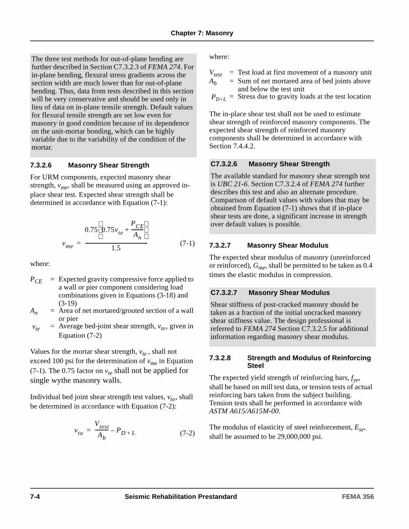
Chapter 7: Masonry
7.3.2.6 Masonry Shear Strength
For URM components, expected masonry shear strength, vme, shall be measured using an approved in-place shear test. Expected shear strength shall be determined in accordance with Equation (7-1):
(7-1)
where:
Values for the mortar shear strength, vte , shall not exceed 100 psi for the determination of vme in Equation (7-1). The 0.75 factor on vte shall not be applied for single wythe masonry walls.
Individual bed joint shear strength test values, vto , shall be determined in accordance with Equation (7-2):
(7-2)
where:
The in-place shear test shall not be used to estimate shear strength of reinforced masonry components. The expected shear strength of reinforced masonry components shall be determined in accordance with Section 7.4.4.2.
7.3.2.7 Masonry Shear Modulus
The expected shear modulus of masonry (unreinforced or reinforced), Gme, shall be permitted to be taken as 0.4 times the elastic modulus in compression.
7.3.2.8 Strength and Modulus of Reinforcing Steel
The expected yield strength of reinforcing bars, fye, shall be based on mill test data, or tension tests of actual reinforcing bars taken from the subject building. Tension tests shall be performed in accordance with ASTM A615/A615M-00.
The modulus of elasticity of steel reinforcement, Ese, shall be assumed to be 29,000,000 psi.
The three test methods for out-of-plane bending are further described in Section C7.3.2.3 of FEMA 274. For in-plane bending, flexural stress gradients across the section width are much lower than for out-of-plane bending. Thus, data from tests described in this section will be very conservative and should be used only in lieu of data on in-plane tensile strength. Default values for flexural tensile strength are set low even for masonry in good condition because of its dependence on the unit-mortar bonding, which can be highly variable due to the variability of the condition of the mortar.
PCE = Expected gravity compressive force applied to a wall or pier component considering load combinations given in Equations (3-18) and (3-19)
An = Area of net mortared/grouted section of a wall or pier
vte = Average bed-joint shear strength, vto, given in Equation (7-2)
vme
0.75 0.75vte
PCE
An----------+
1.5---------------------------------------------------=
vto
Vtest
Ab----------- PD L+–=
Vtest = Test load at first movement of a masonry unitAb = Sum of net mortared area of bed joints above
and below the test unit PD+L = Stress due to gravity loads at the test location
C7.3.2.6 Masonry Shear Strength
The available standard for masonry shear strength test is UBC 21-6. Section C7.3.2.4 of FEMA 274 further describes this test and also an alternate procedure. Comparison of default values with values that may be obtained from Equation (7-1) shows that if in-place shear tests are done, a significant increase in strength over default values is possible.
C7.3.2.7 Masonry Shear Modulus
Shear stiffness of post-cracked masonry should be taken as a fraction of the initial uncracked masonry shear stiffness value. The design professional is referred to FEMA 274 Section C7.3.2.5 for additional information regarding masonry shear modulus.
7-4 Seismic Rehabilitation Prestandard FEMA 356
Chapter 7: Masonry
7.3.2.9 Minimum Number of Tests
Materials testing is not required if material properties are available from original construction documents that include material test records or material test reports.
7.3.2.9.1 Usual Testing
The minimum number of tests to determine masonry and reinforcing steel material properties for usual data collection shall be based on the following criteria:
1. If the specified design strength of the masonry is known, and the masonry is in good or fair condition, at least one test shall be performed on samples of each different masonry strength used in the construction of the building, with a minimum of three tests performed for the entire building. If the masonry is in poor condition, additional tests shall be performed to determine the extent of the reduced material properties.
2. If the specified design strength of the masonry is not known, at least one test shall be performed on each type of component, with a minimum of six tests performed on the entire building.
3. If the specified design strength of the reinforcing steel is known, use of nominal or specified material properties shall be permitted without additional testing.
4. If the specified design strength of the reinforcing steel is not known, at least two strength coupons of reinforcing steel shall be removed from a building for testing.
7.3.2.9.2 Comprehensive Testing
The minimum number of tests necessary to quantify properties by in-place testing for comprehensive data collection shall be based on the following criteria:
1. For masonry in good or fair condition as defined in this standard, a minimum of three tests shall be performed for each masonry type, and for each three floors of construction or 3,000 square feet of wall
surface, if original construction records are available that specify material properties; six tests shall be performed if original construction records are not available. At least two tests shall be performed for each wall or line of wall elements providing a common resistance to lateral forces. A minimum of eight tests shall be performed for each building.
2. For masonry in poor condition as defined in this standard, additional tests shall be done to estimate material strengths in regions where properties differ, or nondestructive condition assessment tests in accordance with Section 7.3.3.2 shall be used to quantify variations in material strengths.
Samples for tests shall be taken at locations representative of the material conditions throughout the entire building, taking into account variations in workmanship at different story levels, variations in weathering of the exterior surfaces, and variations in the condition of the interior surfaces due to deterioration caused by leaks and condensation of water and/or the deleterious effects of other substances contained within the building.
An increased sample size shall be permitted to improve the confidence level. The relation between sample size and confidence shall be as defined in ASTM E139-00.
If the coefficient of variation in test measurements exceeds 25%, the number of tests performed shall be doubled.
If mean values from in situ material tests are less than the default values prescribed in Section 7.3.2.10, the number of tests performed shall be doubled.
C7.3.2.9 Minimum Number of Tests
The number and location of material tests should be selected to provide sufficient information to adequately define the existing condition of materials in the building. Test locations should be identified in those masonry components that are determined to be critical to the primary path of lateral-force resistance.
FEMA 356 Seismic Rehabilitation Prestandard 7-5
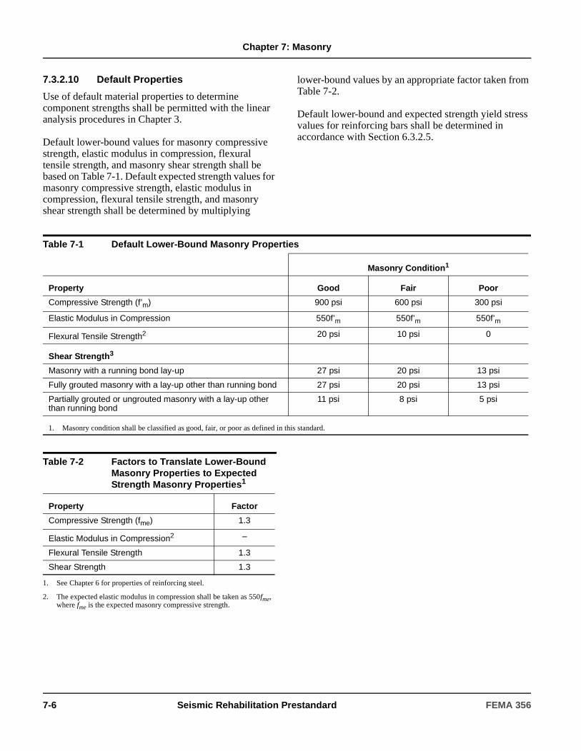
Chapter 7: Masonry
7.3.2.10 Default Properties
Use of default material properties to determine component strengths shall be permitted with the linear analysis procedures in Chapter 3.
Default lower-bound values for masonry compressive strength, elastic modulus in compression, flexural tensile strength, and masonry shear strength shall be based on Table 7-1. Default expected strength values for masonry compressive strength, elastic modulus in compression, flexural tensile strength, and masonry shear strength shall be determined by multiplying
lower-bound values by an appropriate factor taken from Table 7-2.
Default lower-bound and expected strength yield stress values for reinforcing bars shall be determined in accordance with Section 6.3.2.5.
Table 7-1 Default Lower-Bound Masonry Properties
Masonry Condition1
Property Good Fair Poor
Compressive Strength (f’m) 900 psi 600 psi 300 psi
Elastic Modulus in Compression 550f’m 550f’m 550f’m
Flexural Tensile Strength2 20 psi 10 psi 0
Shear Strength3
Masonry with a running bond lay-up 27 psi 20 psi 13 psi
Fully grouted masonry with a lay-up other than running bond 27 psi 20 psi 13 psi
Partially grouted or ungrouted masonry with a lay-up other than running bond
11 psi 8 psi 5 psi
1. Masonry condition shall be classified as good, fair, or poor as defined in this standard.
Table 7-2 Factors to Translate Lower-Bound Masonry Properties to Expected Strength Masonry Properties1
Property Factor
Compressive Strength (fme) 1.3
Elastic Modulus in Compression2 –
Flexural Tensile Strength 1.3
Shear Strength 1.3
1. See Chapter 6 for properties of reinforcing steel.
2. The expected elastic modulus in compression shall be taken as 550fme, where fme is the expected masonry compressive strength.
7-6 Seismic Rehabilitation Prestandard FEMA 356
Chapter 7: Masonry
7.3.3 Condition Assessment
A condition assessment of the existing building and site conditions shall be performed as specified in Sections 7.3.3.1 through 7.3.3.3.
A condition assessment shall include the following:
1. The physical condition of primary and secondary components shall be examined and the presence of any degradation shall be noted.
2. The presence and configuration of components and their connections, and the continuity of load paths between components, elements, and systems shall be verified or established.
3. Other conditions, including the presence and attachment of veneer, neighboring party walls and buildings, presence of nonstructural components, prior remodeling, and limitations for rehabilitation that may influence building performance, shall be identified and documented.
The condition of the masonry shall be classified as good, fair, or poor as defined in this standard, based on the results of visual examination conducted in accordance with Section 7.3.3.1.
7.3.3.1 Visual Condition Assessment
The size and location of all masonry shear and bearing walls shall be determined by visual examination. The orientation and placement of the walls shall be noted. Overall dimensions of masonry components shall be measured or determined from plans, including wall heights, lengths, and thicknesses. Locations and sizes of window and door openings shall be measured or determined from plans. The distribution of gravity loads to bearing walls shall be estimated.
Walls shall be classified as reinforced or unreinforced, composite or noncomposite, and grouted, partially grouted, or ungrouted. For reinforced masonry (RM) construction, the size and spacing of horizontal and
C7.3.3 Condition Assessment
Buildings are often constructed with veneer as an architectural finish, which may make the wall appear thicker than the actual structural thickness. In many areas of the country, the veneer wythe is separated from the structural wall by an air space to provide ventilation and moisture control. This is called cavity wall construction. In this case, the veneer may be anchored, but does not add any strength to the assembly.
In areas of the southwest United States and along the California coast (as well as other regions), the veneer is placed directly against the building wall. It will be in a running bond pattern without a header course. Other patterns are also seen. If the veneer is not anchored, or has a layer of building paper between it and the inner wythe, it cannot be considered as part of the structural wall.
Veneer on modern buildings may be adhered or anchored. In either case, the veneer is a weight to be considered, but does not contribute to a wall’s strength. In all cases, the veneer must be anchored to prevent its detaching during an earthquake. Requirements for veneer are specified in Chapter 11.
Face brick bonded to the inner wythes with a regular pattern of header courses is not veneer. In this case, the outer wythes are part of the structural wall, and can be used in evaluating the height-to-thickness ratio of the wall.
See Section C7.3.2.1 regarding the use of FEMA 306, FEMA 307, and FEMA 308 for additional information in classifying the condition of masonry.
FEMA 356 Seismic Rehabilitation Prestandard 7-7
Chapter 7: Masonry
vertical reinforcement shall be estimated. For multi-wythe construction, the number of wythes shall be noted, as well as the distance between wythes, and the placement of inter-wythe ties. The condition and attachment of veneer wythes shall be noted. For grouted construction, the quality of grout placement shall be assessed. For partially grouted walls, the locations of grout placement shall be identified.
The type and condition of the mortar and mortar joints shall be determined. Mortar shall be examined for weathering, erosion, and hardness, and to identify the condition of any repointing, including cracks, internal voids, weak components, and/or deteriorated or eroded mortar. Horizontal cracks in bed joints, vertical cracks in head joints and masonry units, and diagonal cracks near openings shall be noted.
Vertical components that are not straight shall be identified. Bulging or undulations in walls shall be observed, as well as separation of exterior wythes, out-of-plumb walls, and leaning parapets or chimneys.
Connections between masonry walls and floors or roofs shall be examined to identify details and condition. If construction drawings are available, a minimum of three connections shall be inspected for each connection type. If no deviations from the drawings are found, the sample shall be considered representative. If drawings are unavailable, or if deviations are noted between the drawings and constructed work, then a random sample of connections shall be inspected until a representative pattern of connections is identified.
7.3.3.2 Comprehensive Condition Assessment
The following nondestructive tests shall be permitted to quantify and confirm the uniformity of construction quality and the presence and degree of deterioration for comprehensive data collection:
1. Ultrasonic or mechanical pulse velocity to detect variations in the density and modulus of masonry materials and to detect the presence of cracks and discontinuities.
2. Impact echo test to confirm whether reinforced walls are grouted.
3. Radiography to confirm location of reinforcing steel.
The location and number of nondestructive tests shall be determined in accordance with the requirements of Section 7.3.2.9.2.
C7.3.3.2 Comprehensive Condition Assessment
Nondestructive tests may be used to supplement the visual observations required by Section 7.3.3.1.
C7.3.3.2.1 Ultrasonic Pulse Velocity
Measurement of the velocity of ultrasonic pulses through a wall can detect variations in the density and modulus of masonry materials as well as the presence of cracks and discontinuities. Transmission times for pulses traveling through a wall (direct method) or between two points on the same side of a wall (indirect method) are measured and used to infer wave velocity.
Test equipment with wave frequencies in the range of 50 kHz has been shown to be appropriate for masonry walls. Use of equipment with higher frequency waves is not recommended because the short wave length and high attenuation are not consistent with typical dimensions of masonry units. Test locations should be sufficiently close to identify zones with different properties. Contour maps of direct transmission wave velocities can be constructed to assess the overall homogeneity of a wall elevation. For indirect test data, vertical or horizontal distance can be plotted versus travel time to identify changes in wave velocity (slope of the curve). Abrupt changes in slope will identify locations of cracks or flaws.
Ultrasonic methods are not applicable for masonry of poor quality or low modulus, or with many flaws and cracks. The method is sensitive to surface condition, the coupling material used between the transducer or receiver and the brick, and the pressure applied to the transducer.
The use of ultrasonic pulse velocity methods with masonry walls has been researched extensively by Calvi (1988); Epperson and Abrams (1989); Kingsley et al. (1987). A standard for the use of ultrasonic methods for masonry is currently under development in Europe with RILEM Committee 76LUM.
7-8 Seismic Rehabilitation Prestandard FEMA 356

Chapter 7: Masonry
7.3.3.3 Supplemental Tests
Supplemental tests shall be permitted to enhance the level of confidence in masonry material properties, or the assessment of masonry condition for justifying the use of a higher knowledge factor, as specified in Section 7.3.4.
C7.3.3.2.2 Mechanical Pulse Velocity
The mechanical pulse velocity test consists of impacting a wall with a hammer blow and measuring the travel time of a sonic wave across a specified gage distance. An impact hammer is equipped with a load cell or accelerometer to detect the time of impact. A distant accelerometer is fixed to a wall to detect the arrival time of the pulse. Wave velocity is determined by dividing the gage length by the travel time. The form and duration of the generated wave can be varied by changing the material on the hammer cap.
The generated pulse has a lower frequency and higher energy content than an ultrasonic pulse, resulting in longer travel distances and less sensitivity to small variations in masonry properties and minor cracking. The mechanical pulse method should be used in lieu of the ultrasonic pulse method when overall mean properties of a large portion of masonry are of interest.
The use of mechanical pulse velocity measurements for masonry condition assessments has been confirmed through research by Epperson and Abrams (1989) and Kingsley et al. (1987). Although no standard exists for mechanical pulse velocity tests with masonry, a standard for concrete materials (ASTM C597-97) does exist.
C7.3.3.2.3 Impact Echo
The impact-echo technique can be useful for nondestructive determination of the location of void areas within grouted reinforced walls - Sansalone and Carino (1988). Commercial devices are available or systems can be assembled using available electronic components. Since this technique cannot distinguish between a shrinkage crack at the grout-unit interface and a complete void in the grout, drilling of small holes in the bed joint or examination using an optical borescope should be performed to verify the exact condition.
C7.3.3.2.4 Radiography
A number of commercial radiographic (x-ray) devices exist that can be used to identify the location of reinforcing steel in masonry walls. They are also useful for locating bed-joint reinforcing steel, masonry ties and anchors, and conduits and pipes. The better devices can locate a No. 6 bar at depths up to approximately six inches; however, this means that for a 12-inch-thick concrete masonry wall, a bar located off-center cannot be found when access is limited to only one side of the wall. These devices are not able to locate or determine the length of reinforcing bar splices in walls in most cases. They work best for identifying the location of single isolated bars and become less useful when the congestion of reinforcing bars increases.
C7.3.3.3 Supplemental Tests
Ancillary tests are recommended, but not required, to enhance the level of confidence in masonry material properties, or to assess condition. Possible supplemental tests are described below.
C7.3.3.3.1 Surface Hardness
The surface hardness of exterior-wythe masonry can be evaluated using the Schmidt rebound hammer. Research has shown that the technique is sensitive to differences in masonry strength, but cannot by itself be used to determine absolute strength. A Type N hammer (5000 lb.) is recommended for normal-strength masonry, while a Type L hammer (1600 lb.) is recommended for lower-strength masonry. Impacts at the same test location should be continued until consistent readings are obtained, because surface roughness can affect initial readings.
The method is limited to tests of only the surface wythe. Tuckpointing may influence readings and the method is not sensitive to cracks.
Measurement of surface hardness for masonry walls has been studied by Noland et al. (1987).
FEMA 356 Seismic Rehabilitation Prestandard 7-9
Chapter 7: Masonry
C7.3.3.3.2 Vertical Compressive Stress
In situ vertical compressive stress resisted by the masonry can be measured using a thin hydraulic flat jack that is inserted into a removed mortar bed joint. Pressure in the flat jack is increased until distortions in the brickwork are reduced to the pre-cut condition. Existing vertical compressive stress is inferred from the jack hydraulic pressure, using correction factors for the shape and stiffness of the flat jack.
The method is useful for measurement of gravity load distribution, flexural stresses in out-of-plane walls, and stresses in masonry veneer walls that are compressed by a surrounding concrete frame. The test is limited to only the face wythe of masonry.
Not less than three tests should be done for each section of the building for which it is desired to measure in situ vertical stress. The number and location of tests should be determined based on the building configuration and the likelihood of overstress conditions.
C7.3.3.3.3 Diagonal Compression Test
A square panel of masonry is subjected to a compressive force applied at two opposite corners along a diagonal until the panel cracks. Shear strength is inferred from the measured diagonal compressive force based on a theoretical distribution of shear and normal stress for a homogeneous and elastic continuum. Using the same theory, shear modulus is inferred from measured diagonal compressive stress and strain.
Extrapolation of the test data to actual masonry walls is difficult because the ratio of shear to normal stress is fixed at a constant ratio of 1.0 for the test specimens. Also, the distribution of shear and normal stresses across a bed joint may not be as uniform for a test specimen as for an actual wall. Lastly, any redistribution of stresses after the first cracking will not be represented with the theoretical stress distributions. Thus, the test data cannot be useful to predict nonlinear behavior.
If the size of the masonry units relative to the panel dimension is large, masonry properties will be not continuous, but discrete. Test panels should be a minimum of four feet square. The high cost and disruption of extracting a number of panels this size may be impractical. The standard test method specified in ASTM E519-81 may be used.
C7.3.3.3.4 Large-Scale Load Tests
[Large-scale destructive tests may be done on portions of a masonry component or element to (1) increase the confidence level on overall structural properties, (2) obtain performance data on archaic building materials and construction materials, (3) quantify effects of complex edge and boundary conditions around openings and two-way spanning, and (4) verify or calibrate analytical models. Large-scale load tests do not necessarily have to be run to the ultimate limit state. They may have value for simply demonstrating structural integrity up to some specific Performance Level.
Out-of-plane strength and behavior of masonry walls can be determined with air-bag tests. Behavior of test panels incorporating connections and edge details can be determined from such a test, in addition to flexural and arching properties of a solid or perforated wall. Strength and deformation capacity under in-plane lateral forces can be determined by loading an individual portion of wall that is cut free of the surrounding masonry. Loading actuators are reacted against adjacent and stronger portions of masonry. Such testing is particularly useful when the wall is composed of different materials that cannot be evaluated by testing an individual unit of an individual wythe.
Visual and nondestructive surveys should be used to identify locations for test samples.
Standards for laboratory test methods are published by ASTM. Procedures for removal and transportation of masonry samples are given in NBS 62.
Large-scale tests are expensive and limited to a single or few samples. They may result in considerable local damage and may require substantial reconstruction near the sample location. Test data must be extrapolated to the remainder of the system, based on a low confidence level.
7-10 Seismic Rehabilitation Prestandard FEMA 356
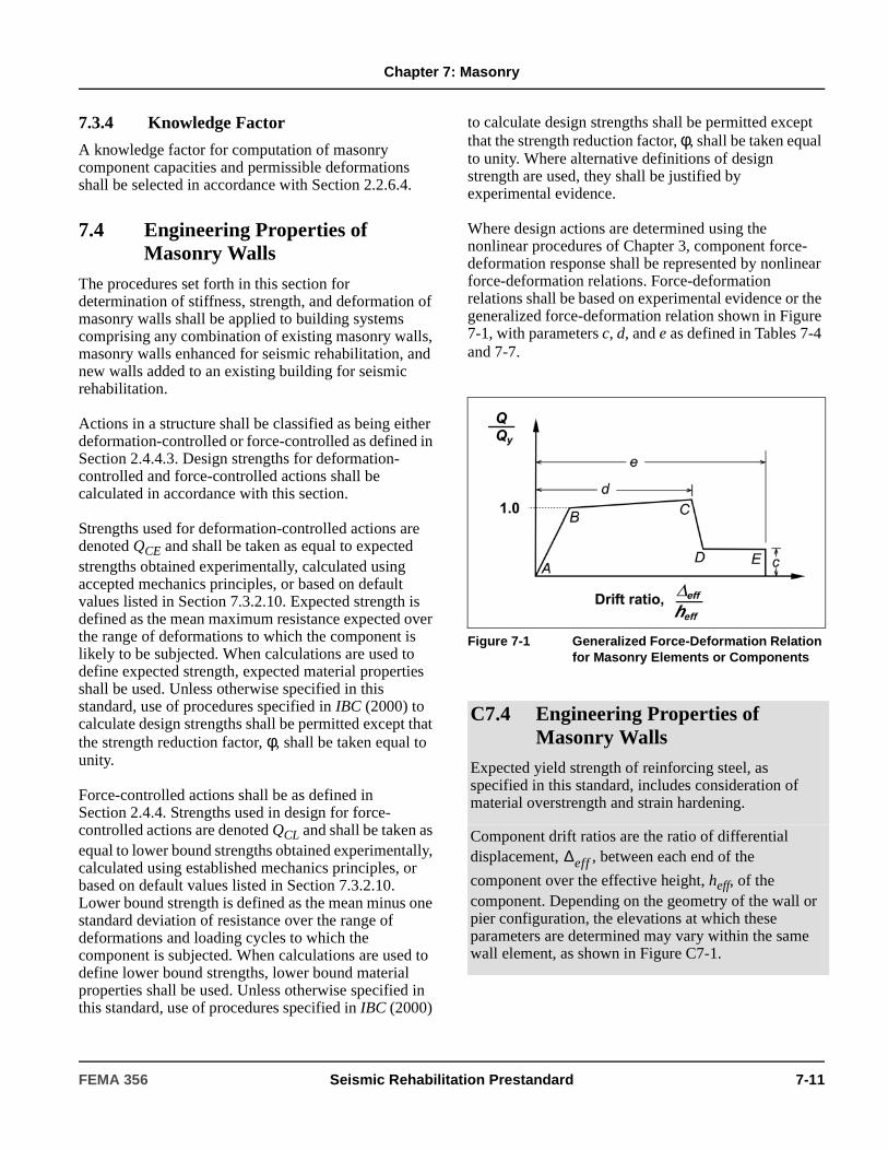
Chapter 7: Masonry
7.3.4 Knowledge Factor
A knowledge factor for computation of masonry component capacities and permissible deformations shall be selected in accordance with Section 2.2.6.4.
7.4 Engineering Properties of Masonry Walls
The procedures set forth in this section for determination of stiffness, strength, and deformation of masonry walls shall be applied to building systems comprising any combination of existing masonry walls, masonry walls enhanced for seismic rehabilitation, and new walls added to an existing building for seismic rehabilitation.
Actions in a structure shall be classified as being either deformation-controlled or force-controlled as defined in Section 2.4.4.3. Design strengths for deformation-controlled and force-controlled actions shall be calculated in accordance with this section.
Strengths used for deformation-controlled actions are denoted QCE and shall be taken as equal to expected strengths obtained experimentally, calculated using accepted mechanics principles, or based on default values listed in Section 7.3.2.10. Expected strength is defined as the mean maximum resistance expected over the range of deformations to which the component is likely to be subjected. When calculations are used to define expected strength, expected material properties shall be used. Unless otherwise specified in this standard, use of procedures specified in IBC (2000) to calculate design strengths shall be permitted except that the strength reduction factor, φ, shall be taken equal to unity.
Force-controlled actions shall be as defined in Section 2.4.4. Strengths used in design for force-controlled actions are denoted QCL and shall be taken as equal to lower bound strengths obtained experimentally, calculated using established mechanics principles, or based on default values listed in Section 7.3.2.10. Lower bound strength is defined as the mean minus one standard deviation of resistance over the range of deformations and loading cycles to which the component is subjected. When calculations are used to define lower bound strengths, lower bound material properties shall be used. Unless otherwise specified in this standard, use of procedures specified in IBC (2000)
to calculate design strengths shall be permitted except that the strength reduction factor, φ, shall be taken equal to unity. Where alternative definitions of design strength are used, they shall be justified by experimental evidence.
Where design actions are determined using the nonlinear procedures of Chapter 3, component force-deformation response shall be represented by nonlinear force-deformation relations. Force-deformation relations shall be based on experimental evidence or the generalized force-deformation relation shown in Figure 7-1, with parameters c, d, and e as defined in Tables 7-4 and 7-7.
Figure 7-1 Generalized Force-Deformation Relation for Masonry Elements or Components
C7.4 Engineering Properties of Masonry Walls
Expected yield strength of reinforcing steel, as specified in this standard, includes consideration of material overstrength and strain hardening.
Component drift ratios are the ratio of differential displacement, , between each end of the
component over the effective height, heff, of the component. Depending on the geometry of the wall or pier configuration, the elevations at which these parameters are determined may vary within the same wall element, as shown in Figure C7-1.
∆eff
FEMA 356 Seismic Rehabilitation Prestandard 7-11
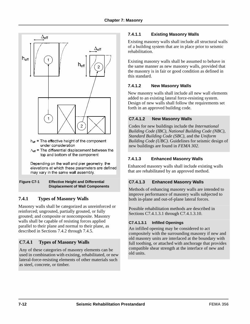
Chapter 7: Masonry
7.4.1 Types of Masonry Walls
Masonry walls shall be categorized as unreinforced or reinforced; ungrouted, partially grouted, or fully grouted; and composite or noncomposite. Masonry walls shall be capable of resisting forces applied parallel to their plane and normal to their plane, as described in Sections 7.4.2 through 7.4.5.
7.4.1.1 Existing Masonry Walls
Existing masonry walls shall include all structural walls of a building system that are in place prior to seismic rehabilitation.
Existing masonry walls shall be assumed to behave in the same manner as new masonry walls, provided that the masonry is in fair or good condition as defined in this standard.
7.4.1.2 New Masonry Walls
New masonry walls shall include all new wall elements added to an existing lateral force-resisting system. Design of new walls shall follow the requirements set forth in an approved building code.
7.4.1.3 Enhanced Masonry Walls
Enhanced masonry walls shall include existing walls that are rehabilitated by an approved method.
Figure C7-1 Effective Height and Differential Displacement of Wall Components
C7.4.1 Types of Masonry Walls
Any of these categories of masonry elements can be used in combination with existing, rehabilitated, or new lateral-force-resisting elements of other materials such as steel, concrete, or timber.
C7.4.1.2 New Masonry Walls
Codes for new buildings include the International Building Code (IBC), National Building Code (NBC), Standard Building Code (SBC), and the Uniform Building Code (UBC). Guidelines for seismic design of new buildings are found in FEMA 302.
C7.4.1.3 Enhanced Masonry Walls
Methods of enhancing masonry walls are intended to improve performance of masonry walls subjected to both in-plane and out-of-plane lateral forces.
Possible rehabilitation methods are described in Sections C7.4.1.3.1 through C7.4.1.3.10.
C7.4.1.3.1 Infilled Openings
An infilled opening may be considered to act compositely with the surrounding masonry if new and old masonry units are interlaced at the boundary with full toothing, or attached with anchorage that provides compatible shear strength at the interface of new and old units.
7-12 Seismic Rehabilitation Prestandard FEMA 356

Chapter 7: Masonry
Stiffness assumptions, strength criteria, and acceptable deformations for masonry walls with infilled openings should be the same as given for non-rehabilitated solid masonry walls; differences in elastic moduli and strengths for the new and old masonry walls should be considered for the composite section.
C7.4.1.3.2 Enlarged Openings
Openings in URM shear walls may be enlarged by removing portions of masonry above or below windows or doors.
Openings are enlarged to increase the height-to-length aspect ratio of piers so that the limit state may be altered from shear to flexure. This method is only applicable to URM walls.
Stiffness assumptions, strength criteria, and acceptable deformations for URM walls with enlarged openings shall be reassessed to reflect the final condition of the wall.
C7.4.1.3.3 Shotcrete
An existing masonry wall with an application of shotcrete may be considered to behave as a composite section if anchorage is provided at the shotcrete-masonry interface to transfer the shear forces calculated in accordance with Chapter 3. Stresses in the masonry and shotcrete should be determined considering the difference in elastic moduli for each material, or the existing masonry wall should be neglected and the new shotcrete layer should be designed to resist all of the force.
Stiffness assumptions, strength criteria, and acceptable deformations for masonry components with shotcrete should be the same as that for new reinforced concrete components. Variations in boundary conditions should be considered.
C7.4.1.3.4 Coatings for Unreinforced Masonry Walls
A coated masonry wall may be considered a composite section as long as anchorage is provided at the interface between the coating and the masonry wall to transfer shear forces. Stresses in the masonry and coating should be determined considering the difference in elastic moduli for each material. If stresses exceed expected strengths of the coating material, then the coating should be considered ineffective.
Stiffness assumptions, strength criteria, and acceptable deformations for coated masonry walls should be the same as that for existing URM walls.
C7.4.1.3.5 Reinforced Cores for Unreinforced Masonry Walls
A reinforced-cored masonry wall should be considered to behave as a reinforced masonry wall, provided that the bond between the new reinforcement and the grout and between the grout and the cored surface are capable of transferring seismic forces computed in accordance with Chapter 3. Vertical reinforcement should be anchored at the base of the wall to resist the full tensile strength of the wall.
Grout in new reinforced cores should consist of cementitious materials whose hardened properties are compatible with those of the surrounding masonry.
Adequate shear strength must exist, or should be provided, so that the strength of the new vertical reinforcement can be developed.
Stiffness assumptions, strength criteria, and acceptable deformations for URM walls with reinforced cores should be the same as that for existing reinforced walls.
C7.4.1.3.6 Prestressed Cores for Unreinforced Masonry Walls
A prestressed-cored masonry wall with unbonded tendons should be considered to behave as a URM wall with increased vertical compressive stress.
Losses in prestressing force due to creep and shrinkage of the masonry should be accounted for in analyses conducted in accordance with Chapter 3.
Stiffness assumptions, strength criteria, and acceptable deformations for URM walls with unbonded prestressing tendons should be the same as for existing unreinforced masonry walls subjected to vertical compressive stress.
C7.4.1.3.7 Grout Injections
Grout used for filling voids and cracks should have strength, modulus, and thermal properties compatible with the existing masonry.
Inspections should be conducted in accordance with Chapter 2 during the grouting process to ensure that voids are completely filled with grout.
FEMA 356 Seismic Rehabilitation Prestandard 7-13

Chapter 7: Masonry
7.4.2 Unreinforced Masonry Walls and Piers In-Plane
Engineering properties of unreinforced masonry (URM) walls subjected to lateral forces applied parallel to their plane shall be determined in accordance with this section. Requirements of this section shall apply to cantilevered shear walls that are fixed against rotation at their base, and piers between window or door openings that are fixed against rotation top and bottom.
Stiffness and strength criteria presented in this section shall apply to both the Linear Static and Nonlinear Static Procedures prescribed in Chapter 3.
7.4.2.1 Stiffness
The lateral stiffness of masonry walls subjected to lateral in-plane forces shall be determined considering both flexural and shear deformations.
The masonry assemblage of units, mortar, and grout shall be considered to be a homogeneous medium for stiffness computations with an expected elastic modulus in compression, Eme, as specified in Section 7.3.2.4.
For linear procedures, the stiffness of a URM wall or pier resisting lateral forces parallel to its plane shall be considered to be linear and proportional with the geometrical properties of the uncracked section excluding veneer wythes.
Story shears in perforated shear walls shall be distributed to piers in proportion to the relative lateral uncracked stiffness of each pier.
Stiffnesses for existing and enhanced walls shall be determined using principles of mechanics used for new walls.
Stiffness assumptions, strength criteria, and acceptable deformations for masonry walls with grout injections should be the same as that for existing unreinforced or reinforced walls.
C7.4.1.3.8 Repointing
Bond strength of new mortar should be equal to or greater than that of the original mortar. Compressive strength of new mortar should be equal to or less than that of the original mortar.
Stiffness assumptions, strength criteria, and acceptable deformations for repointed masonry walls should be the same as that for existing masonry walls.
C7.4.1.3.9 Braced Masonry Walls
Masonry walls with height-to-thickness ratios in excess of those permitted by Table 7-5, or out-of-plane bending stresses in excess of those permitted by Section 7.4.3.2, may be braced with external structural elements. Adequate strength should be provided in the bracing element and connections to resist the transfer of forces from the masonry wall to the bracing element. Out-of-plane deflections of braced walls resulting from the transfer of vertical floor or roof loadings should be considered.
Stiffness assumptions, strength criteria, and acceptable deformations for braced masonry walls should be the same as that for existing masonry walls. The reduced span of the masonry wall should be considered.
C7.4.1.3.10 Stiffening Elements
Masonry walls with inadequate out-of-plane stiffness or strength may be stiffened with external structural members. The stiffening members should be proportioned to resist a tributary portion of lateral load applied normal to the plane of a masonry wall. Connections at the ends of the stiffening element should be provided to transfer the reaction force. Flexibility of the stiffening element should be considered when estimating lateral drift of a masonry wall panel.
Stiffness assumptions, strength criteria, and acceptable deformations for stiffened masonry walls should be the same as that for existing masonry walls. The stiffening action that the new element provides shall be considered.
C7.4.1.3.11 Veneer Attachment
Veneer not bonded to the structural core of a masonry wall may be rehabilitated by the use of pins inserted through the joints and into the brick substrate. Spacing of pins should match current code requirements given the seismicity of the region.
7-14 Seismic Rehabilitation Prestandard FEMA 356
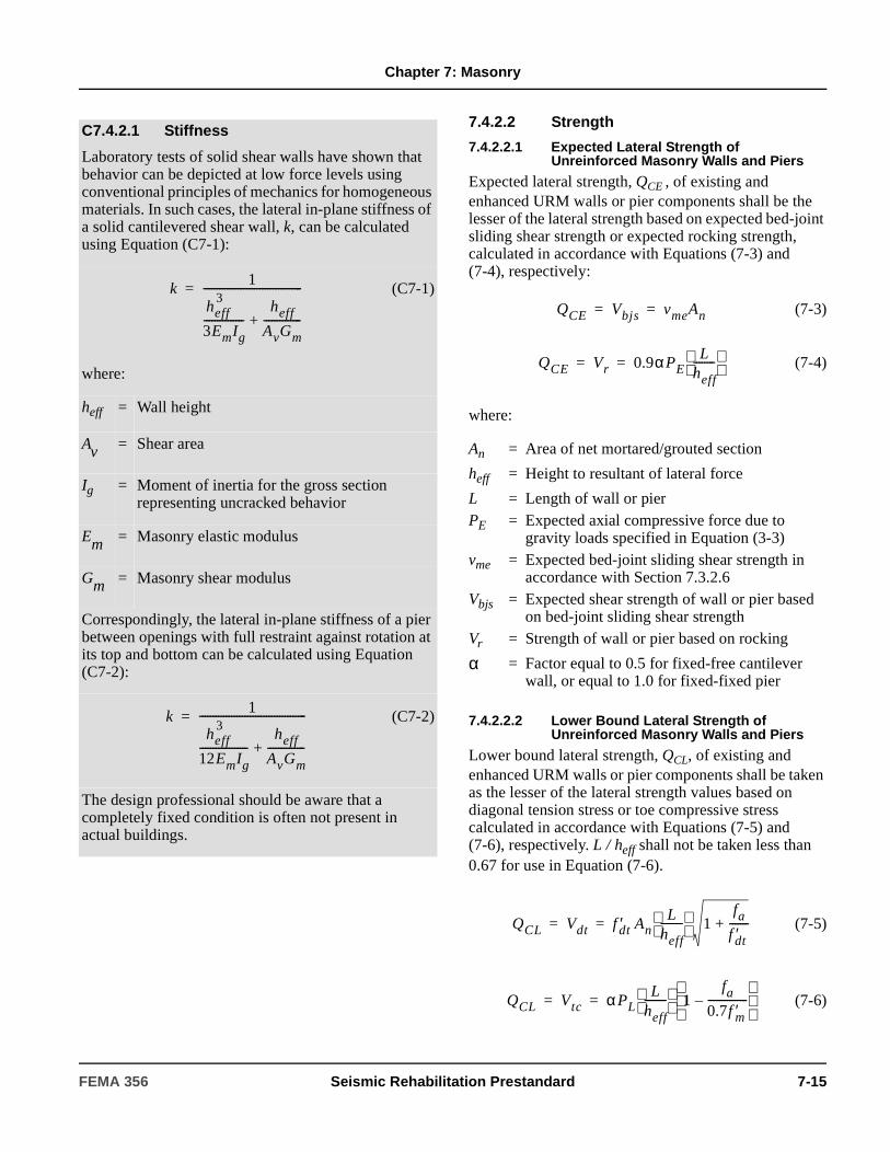
Chapter 7: Masonry
7.4.2.2 Strength
7.4.2.2.1 Expected Lateral Strength of Unreinforced Masonry Walls and Piers
Expected lateral strength, QCE , of existing and enhanced URM walls or pier components shall be the lesser of the lateral strength based on expected bed-joint sliding shear strength or expected rocking strength, calculated in accordance with Equations (7-3) and (7-4), respectively:
(7-3)
(7-4)
where:
7.4.2.2.2 Lower Bound Lateral Strength of Unreinforced Masonry Walls and Piers
Lower bound lateral strength, QCL, of existing and enhanced URM walls or pier components shall be taken as the lesser of the lateral strength values based on diagonal tension stress or toe compressive stress calculated in accordance with Equations (7-5) and (7-6), respectively. L / heff shall not be taken less than 0.67 for use in Equation (7-6).
(7-5)
(7-6)
C7.4.2.1 Stiffness
Laboratory tests of solid shear walls have shown that behavior can be depicted at low force levels using conventional principles of mechanics for homogeneous materials. In such cases, the lateral in-plane stiffness of a solid cantilevered shear wall, k, can be calculated using Equation (C7-1):
(C7-1)
where:
heff = Wall height
Av = Shear area
Ig = Moment of inertia for the gross section representing uncracked behavior
Em = Masonry elastic modulus
Gm = Masonry shear modulus
Correspondingly, the lateral in-plane stiffness of a pier between openings with full restraint against rotation at its top and bottom can be calculated using Equation (C7-2):
(C7-2)
The design professional should be aware that a completely fixed condition is often not present in actual buildings.
k1
heff 3
3EmIg---------------
heff
AvGm--------------+
-------------------------------------=
k1
heff 3
12EmIg------------------
heff
AvGm--------------+
----------------------------------------=
An = Area of net mortared/grouted section
heff = Height to resultant of lateral force
L = Length of wall or pierPE = Expected axial compressive force due to
gravity loads specified in Equation (3-3)vme = Expected bed-joint sliding shear strength in
accordance with Section 7.3.2.6Vbjs = Expected shear strength of wall or pier based
on bed-joint sliding shear strengthVr = Strength of wall or pier based on rocking
α = Factor equal to 0.5 for fixed-free cantilever wall, or equal to 1.0 for fixed-fixed pier
QCE Vbjs vmeAn= =
QCE Vr 0.9αPEL
heff--------
= =
QCL Vdt f ′dt AnL
heff--------
1fa
f ′dt-------+= =
QCL Vtc αPLL
heff--------
1fa
0.7f ′m---------------–
= =
FEMA 356 Seismic Rehabilitation Prestandard 7-15

Chapter 7: Masonry
where An, heff, L, and α are the same as given for Equations (7-3) and (7-4), and:
Substitution of the bed-joint shear strength, vme, for the
diagonal tension strength, , in Equation (7-5) shall be permitted.
The lower bound masonry compressive strength, ,
shall be taken as the expected strength, fme , determined in accordance with Section 7.3.2.3, divided by 1.6.
7.4.2.2.3 Lower Bound Vertical Compressive Strength of Unreinforced Masonry Walls and Piers
Lower bound vertical compressive strength of existing URM walls or pier components shall be limited by lower bound masonry compressive stress in accordance with Equation (7-7):
(7-7)
where is equal to the lower bound compressive
strength determined in accordance with Section 7.3.2.3.
7.4.2.3 Acceptance Criteria
Unreinforced masonry walls and piers shall be considered deformation-controlled components if their expected lateral strength limited by bed-joint sliding shear stress or rocking, as specified in Section 7.4.2.2.1, is less than the lower bound lateral strength limited by diagonal tension or toe compressive stress, as specified in Section 7.4.2.2.2. Unreinforced masonry walls not meeting the criteria for deformation-controlled components shall be considered force-controlled components. Axial compression on URM wall components shall be considered force-controlled.
7.4.2.3.1 Linear Procedures
For the linear procedures in Sections 3.3.1 and 3.3.2, component actions shall be compared with capacities in accordance with Section 3.4.2.2. The expected strength, QCE, for use in Equation (3-20) for components classified as deformation-controlled, shall be the lower of the two expected strengths as determined from Equations (7-3) and (7-4). The m-factors for use with corresponding expected strength shall be obtained from Table 7-3.
fa = Axial compressive stress due to gravity loads specified in Equation (3-3)
f ′dt = Lower bound masonry diagonal tension strength
f ′m = Lower bound masonry compressive strength
PL = Lower bound axial compressive force due to gravity loads specified in Equation (3-4)
Vdt = Lower bound shear strength based on diagonal tension stress for wall or pier
Vtc = Lower bound shear strength based on toe compressive stress for wall or pier
f ′dt
f ′m
QCL PCL 0.80 0.85f ′m An( )= =
f ′m
Table 7-3 Linear Static Procedure—m-factors for URM In-Plane Walls and Piers
m-factors
Performance Level
Limiting Behavioral Mode
IO
Primary Secondary
LS CP LS CP
Bed-Joint Sliding 1 3 4 6 8
Rocking 1.5heff/L(not less than 1)
3heff/L(not less than 1.5)
4heff/L(not less than 2)
6heff/L(not less than 3)
8heff/L(not less than 4)
Interpolation shall be used between table values.
7-16 Seismic Rehabilitation Prestandard FEMA 356

Chapter 7: Masonry
For determination of m-factors from Table 7-3, the vertical compressive stress, fae, shall be based on an expected value of gravity compressive force given by the load combination in Equation (3-3).
7.4.2.3.2 Nonlinear Procedures
For the Nonlinear Static Procedure given in Section 3.3.3, wall and pier components shall meet the requirements of Section 3.4.3.2. For deformation-controlled components, nonlinear deformations shall not exceed the values given in Table 7-4. Variables d and e, representing nonlinear deformation capacities for primary and secondary components, shall be expressed in terms of drift ratio percentages as defined in Figure 7-1. The limiting behavior mode in Table 7-4 shall be identified from the lower of the two expected strengths as determined from Equations (7-3) and (7-4). .
For the Nonlinear Dynamic Procedure given in Section 3.3.4, wall and pier components shall meet the requirements of Section 3.4.3.2. Nonlinear force-deflection relations for deformation-controlled wall and pier components shall be established based on the information given in Table 7-4, or an approved procedure based on a comprehensive evaluation of the hysteretic characteristics of those components.
7.4.3 Unreinforced Masonry Walls Out-of-Plane
As required by Section 2.6.7, URM walls shall be evaluated for out-of-plane inertial forces as isolated components spanning between floor levels, and/or spanning horizontally between columns or pilasters. URM walls shall not be analyzed out-of-plane with the Linear or Nonlinear Static Procedures prescribed in Chapter 3.
7.4.3.1 Stiffness
The out-of-plane stiffness of walls shall be neglected in analytical models of the global structural system in the orthogonal direction.
7.4.3.2 Strength
Unless arching action is considered, flexural cracking shall be limited by the expected tensile stress values given in Section 7.3.2.5.
Arching action shall be considered only if surrounding floor, roof, column, or pilaster elements have sufficient stiffness and strength to resist thrusts from arching of a wall panel, and a condition assessment has been performed to ensure that there are no gaps between a wall panel and the adjacent structure.
The condition of the collar joint shall be considered when estimating the effective thickness of a wall for out-of-plane behavior. The effective void ratio shall be taken as the ratio of the collar joint area without mortar to the total area of the collar joint. Wythes separated by collar joints that are not bonded, or have an effective
Table 7-4 Nonlinear Static Procedure—Simplified Force-Deflection Relations for URM In-Plane Walls and Piers
Acceptance Criteria
Limiting Behavioral Mode
Performance Level
IO%
Primary Secondary
c %
d %
e %
LS%
CP%
LS%
CP%
Bed-Joint Sliding 0.6 0.4 0.8 0.1 0.3 0.4 0.6 0.8
Rocking 0.6 0.4heff /L 0.8heff /L 0.1 0.3heff /L 0.4heff /L 0.6heff /L 0.8heff /L
Interpolation shall be used between table values.
FEMA 356 Seismic Rehabilitation Prestandard 7-17

Chapter 7: Masonry
void ratio greater than 50% shall not be considered part of the effective thickness of the wall.
7.4.3.3 Acceptance Criteria
For the Immediate Occupancy Structural Performance Level, flexural cracking in URM walls due to out-of-plane inertial loading shall not be permitted as limited by the tensile stress requirements of Section 7.4.3.2. For the Life Safety and Collapse Prevention Structural Performance Levels, flexural cracking in URM walls due to out-of-plane inertial loading shall be permitted provided that cracked wall segments will remain stable during dynamic excitation. Stability shall be checked using analytical time-step integration models considering acceleration time histories at the top and base of a wall panel. For the Life Safety and Collapse Prevention Structural Performance Levels, stability need not be checked for walls spanning vertically with a height-to-thickness (h/t) ratio less than that given in Table 7-5.
7.4.4 Reinforced Masonry Walls and Piers In-Plane
7.4.4.1 Stiffness
The stiffness of a reinforced masonry wall or pier component in-plane shall be determined as follows:
1. The shear stiffness of RM wall components shall be based on uncracked section properties.
2. The flexural stiffness of RM wall components shall be based on cracked section properties. Use of a cracked moment of inertia equal to 50 percent of Ig shall be permitted.
In either case, veneer wythes shall not be considered in the calculation of wall component properties. Stiffnesses for existing and new walls shall be assumed to be the same.
7.4.4.2 Strength
The strength of RM wall or pier components in flexure, shear, and axial compression shall be determined in accordance with the requirements of this section. The assumptions, procedures, and requirements of this section shall apply to both existing and new RM wall or pier components.
7.4.4.2.1 Flexural Strength of Walls and Piers
Expected flexural strength of an RM wall or pier shall be determined based on the following assumptions:
1. Stress in reinforcement below the expected yield strength, fye, shall be taken as the expected modulus of elasticity, Ese, times the steel strain. For reinforcement strains larger than those corresponding to the expected yield strength, the stress in the reinforcement shall be considered independent of strain and equal to the expected yield strength, fye.
2. Tensile strength of masonry shall be neglected when calculating the flexural strength of a reinforced masonry cross-section.
3. Flexural compressive stress in masonry shall be assumed to be distributed across an equivalent rectangular stress block. Masonry stress of 0.85 times the expected compressive strength, fme, shall be distributed uniformly over an equivalent
C7.4.3.2 Strength
This section applies to treatment of veneer for out-of-plane behavior of walls only. For in-plane resistance, effective thickness is the sum of all wythes without consideration of the condition of the collar joints.
C7.4.3.3 Acceptance Criteria
For further information on evaluating the stability of unreinforced masonry walls out-of-plane, refer to ABK (1984).
Table 7-5 Permissible h/t Ratios for URM Out-of-Plane Walls
Wall TypesSX1
≤0.24g0.24g<SX1
≤0.37gSX1
>0.37g
Walls of one-story buildings
20 16 13
First-story wall of multistory building
20 18 15
Walls in top story of multistory building
14 14 9
All other walls 20 16 13
7-18 Seismic Rehabilitation Prestandard FEMA 356
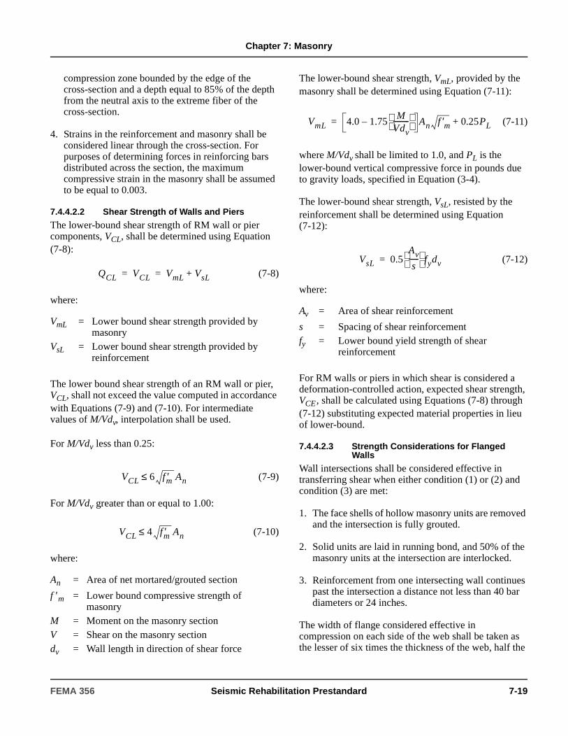
Chapter 7: Masonry
compression zone bounded by the edge of the cross-section and a depth equal to 85% of the depth from the neutral axis to the extreme fiber of the cross-section.
4. Strains in the reinforcement and masonry shall be considered linear through the cross-section. For purposes of determining forces in reinforcing bars distributed across the section, the maximum compressive strain in the masonry shall be assumed to be equal to 0.003.
7.4.4.2.2 Shear Strength of Walls and Piers
The lower-bound shear strength of RM wall or pier components, VCL, shall be determined using Equation (7-8):
(7-8)
where:
The lower bound shear strength of an RM wall or pier, VCL, shall not exceed the value computed in accordance with Equations (7-9) and (7-10). For intermediate values of M/Vdv, interpolation shall be used.
For M/Vdv less than 0.25:
(7-9)
For M/Vdv greater than or equal to 1.00:
(7-10)
where:
The lower-bound shear strength, VmL, provided by the masonry shall be determined using Equation (7-11):
(7-11)
where M/Vdv shall be limited to 1.0, and PL is the lower-bound vertical compressive force in pounds due to gravity loads, specified in Equation (3-4).
The lower-bound shear strength, VsL, resisted by the reinforcement shall be determined using Equation (7-12):
(7-12)
where:
For RM walls or piers in which shear is considered a deformation-controlled action, expected shear strength, VCE , shall be calculated using Equations (7-8) through (7-12) substituting expected material properties in lieu of lower-bound.
7.4.4.2.3 Strength Considerations for Flanged Walls
Wall intersections shall be considered effective in transferring shear when either condition (1) or (2) and condition (3) are met:
1. The face shells of hollow masonry units are removed and the intersection is fully grouted.
2. Solid units are laid in running bond, and 50% of the masonry units at the intersection are interlocked.
3. Reinforcement from one intersecting wall continues past the intersection a distance not less than 40 bar diameters or 24 inches.
The width of flange considered effective in compression on each side of the web shall be taken as the lesser of six times the thickness of the web, half the
VmL = Lower bound shear strength provided by masonry
VsL = Lower bound shear strength provided by reinforcement
An = Area of net mortared/grouted section
f ′m = Lower bound compressive strength of masonry
M = Moment on the masonry sectionV = Shear on the masonry sectiondv = Wall length in direction of shear force
QCL VCL VmL VsL+= =
VCL 6 f ′m An≤
VCL 4 f ′m An≤
Av = Area of shear reinforcement
s = Spacing of shear reinforcementfy = Lower bound yield strength of shear
reinforcement
VmL 4.0 1.75M
Vdv---------
– An f ′m 0.25PL+=
VsL 0.5Av
s------
fydv=
FEMA 356 Seismic Rehabilitation Prestandard 7-19

Chapter 7: Masonry
distance to the next web, or the actual flange on either side of the web wall.
The width of flange considered effective in tension on each side of the web shall be taken as the lesser of 3/4 of the wall height, half the distance to an adjacent web, or the actual flange on either side of the web wall.
7.4.4.2.4 Vertical Compressive Strength of Walls and Piers
Lower bound vertical compressive strength of existing RM wall or pier components shall be determined using Equation (7-13):
(7-13)
where:
7.4.4.3 Acceptance Criteria
The shear required to develop the expected strength of reinforced masonry walls and piers in flexure shall be compared to the lower bound shear strength defined in Section 7.4.4.2.2. For reinforced masonry wall components governed by flexure, flexural actions shall be considered deformation-controlled. For reinforced masonry components governed by shear, shear actions shall be considered deformation-controlled. Axial compression on reinforced masonry wall or pier components shall be considered force-controlled. Expected strength in flexure shall be determined in accordance with Section 7.4.4.2.1, and lower bound strength in axial compression shall be determined in accordance with Section 7.4.4.2.4.
7.4.4.3.1 Linear Procedures
For the linear procedures of Section 3.3.2, component actions shall be compared with capacities in accordance with Section 3.4.2.2. The m-factor for use in Equation (3-20) for those components classified as deformation-controlled shall be as specified in Table 7-6.
For determination of m-factors from Table 7-6, the ratio of vertical compressive stress to expected compressive strength, fae / fme, shall be based on gravity compressive force determined in accordance with the load combinations given in Equations (3-3) and (3-4).
7.4.4.3.2 Nonlinear Procedures
For the Nonlinear Static Procedure of Section 3.3.3, wall and pier components shall meet the requirements of Section 3.4.3.2. Nonlinear deformations on deformation-controlled components shall not exceed the values given in Table 7-7. Variables d and e, representing nonlinear deformation capacities for primary and secondary components, shall be expressed in terms of story drift ratio percentages as defined in Figure 7-1.
For determination of the c, d, and e values and the acceptable drift levels using Table 7-7, the vertical compressive stress, fae, shall be based on gravity compressive force determined in accordance with the load combinations given in Equations (3-3) and (3-4).
For the Nonlinear Dynamic Procedure of Section 3.3.4, wall and pier components shall meet the requirements of Section 3.4.3.2. Nonlinear force-deflection relations for deformation-controlled wall and pier components shall be established based on the information given in Table 7-7, or an approved procedure based on comprehensive evaluation of the hysteretic characteristics of those components.
Acceptable deformations for existing and new walls shall be assumed to be the same.
= Lower bound masonry compressive strength determined in accordance with Section 7.3.2.3
fy = Lower bound reinforcement yield strength determined in accordance with Section 7.3.2.8
QCL PCL 0.8 0.85f ′m An As–( ) As fy+[ ]= =
f ′m
C7.4.4.3.2 Nonlinear Procedures
For primary components, collapse is considered at lateral drift percentages exceeding values of d in Table 7-7, and the Life Safety Structural Performance Level is considered at approximately 75% of d. For secondary components, collapse is considered at lateral drift percentages exceeding the values of e in the table, and the Life Safety Structural Performance Level is considered at approximately 75% of e. Story drift ratio percentages based on these criteria are given in Table 7-7.
7-20 Seismic Rehabilitation Prestandard FEMA 356
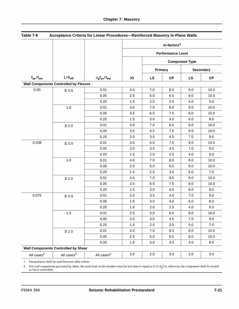
Chapter 7: Masonry
Table 7-6 Acceptance Criteria for Linear Procedures—Reinforced Masonry In-Plane Walls
fae / fme L / heff ρgfye / fme
m-factors1
Performance Level
IO
Component Type
Primary Secondary
LS CP LS CP
Wall Components Controlled by Flexure
0.00 ≤ 0.5 0.01 4.0 7.0 8.0 8.0 10.0
0.05 2.5 5.0 6.5 8.0 10.0
0.20 1.5 2.0 2.5 4.0 5.0
1.0 0.01 4.0 7.0 8.0 8.0 10.0
0.05 3.5 6.5 7.5 8.0 10.0
0.20 1.5 3.0 4.0 6.0 8.0
≥ 2.0 0.01 4.0 7.0 8.0 8.0 10.0
0.05 3.5 6.5 7.5 8.0 10.0
0.20 2.0 3.5 4.5 7.0 9.0
0.038 ≤ 0.5 0.01 3.0 6.0 7.5 8.0 10.0
0.05 2.0 3.5 4.5 7.0 9.0
0.20 1.5 2.0 2.5 4.0 5.0
1.0 0.01 4.0 7.0 8.0 8.0 10.0
0.05 2.5 5.0 6.5 8.0 10.0
0.20 1.5 2.5 3.5 5.0 7.0
≥ 2.0 0.01 4.0 7.0 8.0 8.0 10.0
0.05 3.5 6.5 7.5 8.0 10.0
0.20 1.5 3.0 4.0 6.0 8.0
0.075 ≤ 0.5 0.01 2.0 3.5 4.5 7.0 9.0
0.05 1.5 3.0 4.0 6.0 8.0
0.20 1.0 2.0 2.5 4.0 5.0
1.0 0.01 2.5 5.0 6.5 8.0 10.0
0.05 2.0 3.5 4.5 7.0 9.0
0.20 1.5 2.5 3.5 5.0 7.0
≥ 2.0 0.01 4.0 7.0 8.0 8.0 10.0
0.05 2.5 5.0 6.5 8.0 10.0
0.20 1.5 3.0 4.0 4.0 8.0
Wall Components Controlled by Shear
All cases2 All cases2 All cases2 2.0 2.0 3.0 2.0 3.0
1. Interpolation shall be used between table values.
2. For wall components governed by shear, the axial load on the member must be less than or equal to 0.15 Agf ′m, otherwise the component shall be treated as force-controlled.
FEMA 356 Seismic Rehabilitation Prestandard 7-21
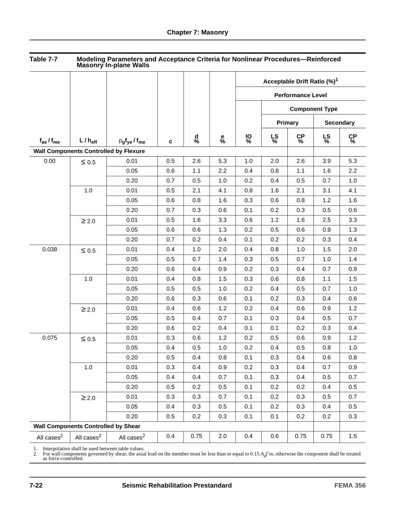
Chapter 7: Masonry
Table 7-7 Modeling Parameters and Acceptance Criteria for Nonlinear Procedures—Reinforced Masonry In-plane Walls
fae / fme L / heff ρgfye / fme cd%
e%
Acceptable Drift Ratio (%)1
Performance Level
IO%
Component Type
Primary Secondary
LS%
CP%
LS%
CP%
Wall Components Controlled by Flexure
0.00 ≤ 0.5 0.01 0.5 2.6 5.3 1.0 2.0 2.6 3.9 5.3
0.05 0.6 1.1 2.2 0.4 0.8 1.1 1.6 2.2
0.20 0.7 0.5 1.0 0.2 0.4 0.5 0.7 1.0
1.0 0.01 0.5 2.1 4.1 0.8 1.6 2.1 3.1 4.1
0.05 0.6 0.8 1.6 0.3 0.6 0.8 1.2 1.6
0.20 0.7 0.3 0.6 0.1 0.2 0.3 0.5 0.6
≥ 2.0 0.01 0.5 1.6 3.3 0.6 1.2 1.6 2.5 3.3
0.05 0.6 0.6 1.3 0.2 0.5 0.6 0.9 1.3
0.20 0.7 0.2 0.4 0.1 0.2 0.2 0.3 0.4
0.038 ≤ 0.5 0.01 0.4 1.0 2.0 0.4 0.8 1.0 1.5 2.0
0.05 0.5 0.7 1.4 0.3 0.5 0.7 1.0 1.4
0.20 0.6 0.4 0.9 0.2 0.3 0.4 0.7 0.9
1.0 0.01 0.4 0.8 1.5 0.3 0.6 0.8 1.1 1.5
0.05 0.5 0.5 1.0 0.2 0.4 0.5 0.7 1.0
0.20 0.6 0.3 0.6 0.1 0.2 0.3 0.4 0.6
≥ 2.0 0.01 0.4 0.6 1.2 0.2 0.4 0.6 0.9 1.2
0.05 0.5 0.4 0.7 0.1 0.3 0.4 0.5 0.7
0.20 0.6 0.2 0.4 0.1 0.1 0.2 0.3 0.4
0.075 ≤ 0.5 0.01 0.3 0.6 1.2 0.2 0.5 0.6 0.9 1.2
0.05 0.4 0.5 1.0 0.2 0.4 0.5 0.8 1.0
0.20 0.5 0.4 0.8 0.1 0.3 0.4 0.6 0.8
1.0 0.01 0.3 0.4 0.9 0.2 0.3 0.4 0.7 0.9
0.05 0.4 0.4 0.7 0.1 0.3 0.4 0.5 0.7
0.20 0.5 0.2 0.5 0.1 0.2 0.2 0.4 0.5
≥ 2.0 0.01 0.3 0.3 0.7 0.1 0.2 0.3 0.5 0.7
0.05 0.4 0.3 0.5 0.1 0.2 0.3 0.4 0.5
0.20 0.5 0.2 0.3 0.1 0.1 0.2 0.2 0.3
Wall Components Controlled by Shear
All cases2 All cases2 All cases2 0.4 0.75 2.0 0.4 0.6 0.75 0.75 1.5
1. Interpolation shall be used between table values.2. For wall components governed by shear, the axial load on the member must be less than or equal to 0.15 Agf ′m, otherwise the component shall be treated
as force-controlled.
7-22 Seismic Rehabilitation Prestandard FEMA 356
Chapter 7: Masonry
7.4.5 Reinforced Masonry Walls Out-of-Plane
Reinforced masonry (RM) walls shall be capable of resisting out-of-plane inertial forces as isolated components spanning between floor levels, and/or spanning horizontally between columns or pilasters. Walls shall not be analyzed out-of-plane with the Linear or Nonlinear Static Procedures prescribed in Chapter 3, but shall be capable of resisting out-of-plane inertial forces as given in Section 2.6.7, or be capable of responding to earthquake motions as determined using the Nonlinear Dynamic Procedure, while satisfying the deflection criteria given in Section 7.4.5.3.
7.4.5.1 Stiffness
RM walls shall be considered local elements spanning out-of-plane between individual story levels.
The out-of-plane stiffness of walls shall be neglected in analytical models of the global structural system.
Stiffness shall be based on the net mortared/grouted area of the uncracked section, provided that net flexural tensile stress does not exceed the expected tensile strength, fte, in accordance with Section 7.3.2.5. Stiffness shall be based on the cracked section for a wall when the net flexural tensile stress exceeds the expected tensile strength.
Stiffnesses for existing and new reinforced out-of-plane walls shall be assumed to be the same.
7.4.5.2 Strength
Expected flexural strength shall be based on Section 7.4.4.2.1. For walls with an h/t ratio exceeding 20, second-order moment effects due to out-of-plane deflections shall be considered.
The strength of new and existing walls shall be assumed to be the same.
7.4.5.3 Acceptance Criteria
Out-of plane forces on reinforced masonry walls shall be considered force-controlled actions. Out-of-plane RM walls shall be sufficiently strong in flexure to resist the out-of-plane loads prescribed in Section 2.6.7.
If the Nonlinear Dynamic Procedure is used, the following performance criteria shall be based on the maximum out-of-plane deflection normal to the plane of a wall.
1. For the Immediate Occupancy Structural Performance Level, the out-of-plane story drift ratio shall be equal to or less than 2%.
2. For the Life Safety Structural Performance Level, the out-of-plane story drift ratio shall be equal to or less than 3%.
3. For the Collapse Prevention Structural Performance Level, the out-of-plane story drift ratio shall be equal to or less than 5%.
Acceptable deformations for existing and new walls shall be assumed to be the same.
7.5 Engineering Properties of Masonry Infills
The requirements of this section shall apply to masonry infill panels comprised of any combination of existing panels, panels enhanced for seismic rehabilitation, and new panels added to an existing building for seismic rehabilitation. The procedures for determination of stiffness, strength, and deformation of masonry infills shall be based on this section and used with the analytical methods and acceptance criteria prescribed in Chapter 3, unless noted otherwise.
Masonry infill panels shall be considered as primary elements of a lateral force-resisting system. If the analysis shows that the surrounding frame remains stable following the loss of an infill panel, infill panels shall not be subject to limits set by the Collapse Prevention Structural Performance Level.
C7.4.5.3 Deformation Acceptance Criteria
The limit states specified in this section are based on the masonry units having significant cracking for IO, masonry units at a point of being dislodged and falling out of the wall for LS, and masonry units on the verge of collapse for CP.
C7.5 Engineering Properties of Masonry Infills
The design professional is referred to FEMA 306, FEMA 307, and FEMA 308 for additional information regarding the engineering properties of masonry infills.
FEMA 356 Seismic Rehabilitation Prestandard 7-23

Chapter 7: Masonry
7.5.1 Types of Masonry Infills
Infills shall include panels built partially or fully within the plane of steel or concrete frames, and bounded by beams and columns.
Infill panel types considered in this standard include unreinforced clay-unit masonry, concrete masonry, and hollow-clay tile masonry. Infills made of stone or glass block are not addressed in this standard.
Infill panels considered isolated from the surrounding frame shall have gaps at top and sides to accommodate maximum expected lateral frame deflections. Isolated panels shall be restrained in the transverse direction to ensure stability under normal forces. Panels in full contact with the frame elements on all four sides are termed “shear infill panels”.
Frame members and connections surrounding infill panels shall be evaluated for frame-infill interaction effects. These effects shall include forces transferred from an infill panel to beams, columns, and connections, and bracing of frame members across a partial length.
7.5.1.1 Existing Masonry Infills
Existing masonry infills considered in this section shall include all structural infills of a building system that are in place prior to seismic rehabilitation. Infill types included in this section consist of unreinforced and ungrouted panels, and composite or noncomposite panels. Existing infill panels subjected to lateral forces applied parallel with their plane shall be considered separately from infills subjected to forces normal to their plane, as described in Sections 7.5.2 and 7.5.3.
Existing masonry infills shall be assumed to behave the same as new masonry infills, provided that the masonry is in good or fair condition as defined in this standard.
7.5.1.2 New Masonry Infills
New masonry infills shall include all new panels added to an existing lateral-force-resisting system for
structural rehabilitation. Infill types shall include unreinforced or reinforced, grouted, ungrouted, or partially grouted, and composite or noncomposite.
7.5.1.3 Enhanced Masonry Infills
Enhanced masonry infill panels shall include existing infills that are rehabilitated by an approved method.
C7.5.1.3 Enhanced Masonry Infills
Masonry infills may be rehabilitated using the methods described in this section. Masonry infills enhanced in accordance with this section should be analyzed using the same procedures and performance criteria used for new infills.
Unless stated otherwise, methods are applicable to unreinforced infills, and are intended to improve performance of masonry infills subjected to both in-plane and out-of-plane lateral forces.
Guidelines from the following sections pertaining to enhancement methods for reinforced masonry walls listed in Section C7.4.1.3, may also apply to unreinforced masonry infill panels: (1) “Infilled Openings,” (2) “Shotcrete,” (3) “Coatings for URM Walls,” (4) “Grout Injections,” (5) “Repointing,” and (6) “Stiffening Elements.” In addition, the following two enhancement methods may apply to masonry infill panels.
C7.5.1.3.1 Boundary Restraints for Infill Panels
Infill panels not in tight contact with perimeter frame members should be restrained for out-of-plane forces.This may be accomplished by installing steel angles or plates on each side of the infills, and welding or bolting the angles or plates to the perimeter frame members.
C7.5.1.3.2 Joints Around Infill Panels
Gaps between an infill panel and the surrounding frame may be filled if integral infill-frame action is assumed for in-plane response.
7-24 Seismic Rehabilitation Prestandard FEMA 356

Chapter 7: Masonry
7.5.2 Masonry Infills In-Plane
The calculation of masonry infill in-plane stiffness and strength based on nonlinear finite element analysis of a composite frame substructure with infill panels that account for the presence of openings and post-yield cracking of masonry shall be permitted. Alternatively, the methods of Sections 7.5.2.1 and 7.5.2.2 shall be used.
7.5.2.1 Stiffness
The elastic in-plane stiffness of a solid unreinforced masonry infill panel prior to cracking shall be represented with an equivalent diagonal compression strut of width, a, given by Equation (7-14). The equivalent strut shall have the same thickness and modulus of elasticity as the infill panel it represents.
(7-14)
where:
and
For noncomposite infill panels, only the wythes in full contact with the frame elements shall be considered when computing in-plane stiffness unless positive anchorage capable of transmitting in-plane forces from frame members to all masonry wythes is provided on all sides of the walls.
Stiffness of cracked unreinforced masonry infill panels shall be represented with equivalent struts; the strut properties shall be determined from analyses that consider the nonlinear behavior of the infilled frame system after the masonry is cracked.
The equivalent compression strut analogy shall be used to represent the elastic stiffness of a perforated unreinforced masonry infill panel; the equivalent strut properties shall be determined from stress analyses of infill walls with representative opening patterns.
Stiffnesses for existing and new infills shall be assumed to be the same.
C7.5.2 Masonry Infills In-Plane
Finite element programs such as FEM 1 may be useful in analyzing masonry infills with openings.
hcol = Column height between centerlines of beams, in.
hinf = Height of infill panel, in.
Efe = Expected modulus of elasticity of frame material, ksi
Eme = Expected modulus of elasticity of infill material, ksi
Icol = Moment of inertia of column, in 4.Linf = Length of infill panel, in.
rinf = Diagonal length of infill panel, in.
tinf = Thickness of infill panel and equivalent strut, in.
a 0.175 λ1hcol( ) 0.4–rinf=
λ1
Emetinf 2sin θ4EfeIcolhinf
--------------------------------
14---
=
= Angle whose tangent is the infill height-to-length aspect ratio, radians
= Coefficient used to determine equivalent width of infill strut
C7.5.2.1 Stiffness
In-plane lateral stiffness of an infilled frame system is not the same as the sum of the frame and infill stiffnesses because of the interaction of the infill with the surrounding frame. Experiments have shown that under lateral forces, the frame tends to separate from the infill near windward lower and leeward upper corners of the infill panels, causing compressive contact stresses to develop between the frame and the infill at the other diagonally opposite corners. Recognizing this behavior, the stiffness contribution of the infill is represented with an equivalent compression strut connecting windward upper and leeward lower corners of the infilled frame. In such an analytical model, if the thickness and modulus of elasticity of the strut are assumed to be the same as those of the infill, the problem is reduced to determining the effective width of the compression strut. Solidly infilled frames may be modeled with a single compression strut in this fashion.
θ
λ1
FEMA 356 Seismic Rehabilitation Prestandard 7-25
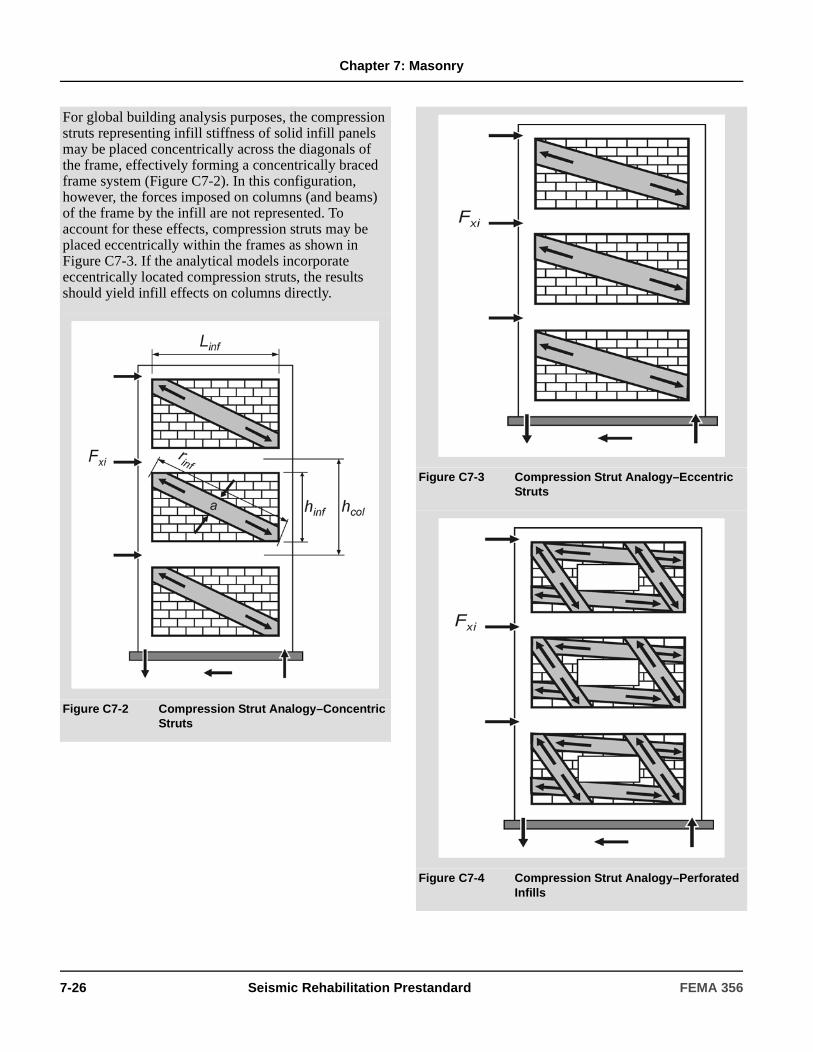
Chapter 7: Masonry
For global building analysis purposes, the compression struts representing infill stiffness of solid infill panels may be placed concentrically across the diagonals of the frame, effectively forming a concentrically braced frame system (Figure C7-2). In this configuration, however, the forces imposed on columns (and beams) of the frame by the infill are not represented. To account for these effects, compression struts may be placed eccentrically within the frames as shown in Figure C7-3. If the analytical models incorporate eccentrically located compression struts, the results should yield infill effects on columns directly.
Figure C7-2 Compression Strut Analogy–Concentric Struts
Figure C7-3 Compression Strut Analogy–Eccentric Struts
Figure C7-4 Compression Strut Analogy–Perforated Infills
7-26 Seismic Rehabilitation Prestandard FEMA 356

Chapter 7: Masonry
7.5.2.2 Strength
The transfer of story shear across a masonry infill panel confined within a concrete or steel frame shall be considered a deformation-controlled action. Expected in-plane panel shear strength shall be determined in accordance with the requirements of this section.
Expected infill shear strength, Vine, shall be calculated in accordance with Equation (7-15):
(7-15)
where:
Expected shear strength of existing infills, fvie, shall not exceed the expected masonry bed-joint shear strength, vme, as determined in accordance with Section 7.3.2.6.
Shear strength of new infill panels, fvie, shall not exceed values specified in an approved building code for zero vertical compressive stress.
For noncomposite infill panels, only the wythes in full contact with the frame elements shall be considered when computing in-plane strength, unless positive anchorage capable of transmitting in-plane forces from frame members to all masonry wythes is provided on all sides of the walls.
7.5.2.3 Acceptance Criteria
7.5.2.3.1 Required Strength of Column Members Adjacent to Infill Panels
The expected flexural and shear strengths of column members adjacent to an infill panel shall exceed the forces resulting from one of the following conditions:
1. The application of the horizontal component of the expected infill strut force at a distance lceff from the top or bottom of the infill panel, where lceff shall be as defined by Equation (7-16):
(7-16)
where shall be as defined by Equation (7-17):
(7-17)
2. The shear force resulting from development of expected column flexural strengths at the top and bottom of a column with a reduced height equal to lceff .
The reduced column length, lceff, in Equation (7-16) shall be equal to the clear height of opening for a captive column braced laterally with a partial height infill.
The requirements of this section shall be waived if the expected masonry shear strength, vme, as measured in accordance with test procedures of Section 7.3.2.6, is less than 20 psi.
7.5.2.3.2 Required Strength of Beam Members Adjacent to Infill Panels
The expected flexural and shear strengths of beam members adjacent to an infill panel shall exceed forces resulting from one of the following conditions:
Alternatively, global analyses may be performed using concentric braced frame models, and the infill effects on columns (or beams) may be evaluated at a local level by applying the strut loads onto the columns (or beams).
Diagonally concentric equivalent struts may also be used to incorporate infill panel stiffnesses into analytical models for perforated infill panels (e.g., infills with window openings), provided that the equivalent stiffness of the infill is determined using appropriate analysis methods (e.g., finite element analysis) in a consistent fashion with the global analytical model. Analysis of local effects, however, must consider various possible stress fields that can potentially develop within the infill. A possible representation of these stress fields with multiple compression struts, as shown in Figure C7-4, have been proposed by Hamburger (1993). Theoretical work and experimental data for determining multiple strut placement and strut properties, however, are not sufficient to establish reliable guidelines; the use of this approach requires judgment on a case-by-case basis.
Ani = Area of net mortared/grouted section across infill panel
fvie = Expected shear strength of masonry infill
QCE Vine Ani fvie= =
lceffaθccos
--------------=
θctan
θctan
hinfaθccos
--------------–
Linf-----------------------------=
FEMA 356 Seismic Rehabilitation Prestandard 7-27
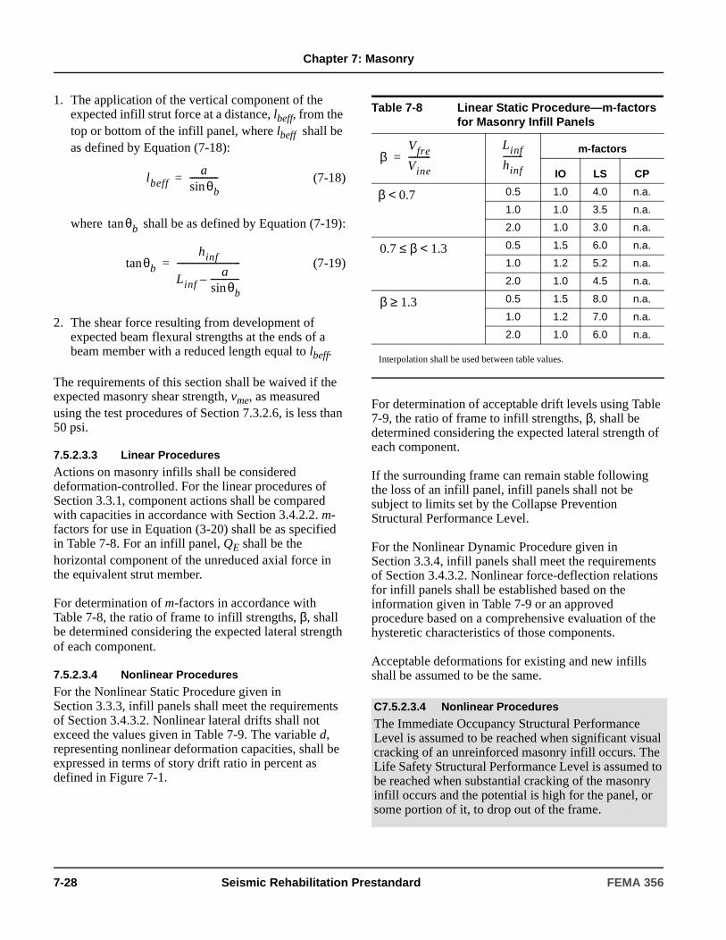
Chapter 7: Masonry
1. The application of the vertical component of the expected infill strut force at a distance, lbeff, from the top or bottom of the infill panel, where lbeff shall be as defined by Equation (7-18):
(7-18)
where shall be as defined by Equation (7-19):
(7-19)
2. The shear force resulting from development of expected beam flexural strengths at the ends of a beam member with a reduced length equal to lbeff.
The requirements of this section shall be waived if the expected masonry shear strength, vme, as measured using the test procedures of Section 7.3.2.6, is less than 50 psi.
7.5.2.3.3 Linear Procedures
Actions on masonry infills shall be considered deformation-controlled. For the linear procedures of Section 3.3.1, component actions shall be compared with capacities in accordance with Section 3.4.2.2. m-factors for use in Equation (3-20) shall be as specified in Table 7-8. For an infill panel, QE shall be the horizontal component of the unreduced axial force in the equivalent strut member.
For determination of m-factors in accordance with Table 7-8, the ratio of frame to infill strengths, β, shall be determined considering the expected lateral strength of each component.
7.5.2.3.4 Nonlinear Procedures
For the Nonlinear Static Procedure given in Section 3.3.3, infill panels shall meet the requirements of Section 3.4.3.2. Nonlinear lateral drifts shall not exceed the values given in Table 7-9. The variable d, representing nonlinear deformation capacities, shall be expressed in terms of story drift ratio in percent as defined in Figure 7-1.
For determination of acceptable drift levels using Table 7-9, the ratio of frame to infill strengths, β, shall be determined considering the expected lateral strength of each component.
If the surrounding frame can remain stable following the loss of an infill panel, infill panels shall not be subject to limits set by the Collapse Prevention Structural Performance Level.
For the Nonlinear Dynamic Procedure given in Section 3.3.4, infill panels shall meet the requirements of Section 3.4.3.2. Nonlinear force-deflection relations for infill panels shall be established based on the information given in Table 7-9 or an approved procedure based on a comprehensive evaluation of the hysteretic characteristics of those components.
Acceptable deformations for existing and new infills shall be assumed to be the same.
lbeffaθbsin
-------------=
θbtan
θbtanhinf
Linfaθbsin
-------------–-----------------------------=
Table 7-8 Linear Static Procedure—m-factors for Masonry Infill Panels
m-factors
IO LS CP
0.5 1.0 4.0 n.a.
1.0 1.0 3.5 n.a.
2.0 1.0 3.0 n.a.
0.5 1.5 6.0 n.a.
1.0 1.2 5.2 n.a.
2.0 1.0 4.5 n.a.
0.5 1.5 8.0 n.a.
1.0 1.2 7.0 n.a.
2.0 1.0 6.0 n.a.
Interpolation shall be used between table values.
C7.5.2.3.4 Nonlinear Procedures
The Immediate Occupancy Structural Performance Level is assumed to be reached when significant visual cracking of an unreinforced masonry infill occurs. The Life Safety Structural Performance Level is assumed to be reached when substantial cracking of the masonry infill occurs and the potential is high for the panel, or some portion of it, to drop out of the frame.
βVfre
Vine----------=
Linf
hinf---------
β 0.7<
0.7 β 1.3<≤
β 1.3≥
7-28 Seismic Rehabilitation Prestandard FEMA 356
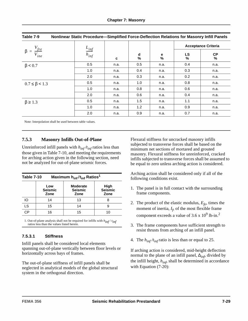
Chapter 7: Masonry
7.5.3 Masonry Infills Out-of-Plane
Unreinforced infill panels with hinf /tinf ratios less than those given in Table 7-10, and meeting the requirements for arching action given in the following section, need not be analyzed for out-of-plane seismic forces.
7.5.3.1 Stiffness
Infill panels shall be considered local elements spanning out-of-plane vertically between floor levels or horizontally across bays of frames.
The out-of-plane stiffness of infill panels shall be neglected in analytical models of the global structural system in the orthogonal direction.
Flexural stiffness for uncracked masonry infills subjected to transverse forces shall be based on the minimum net sections of mortared and grouted masonry. Flexural stiffness for unreinforced, cracked infills subjected to transverse forces shall be assumed to be equal to zero unless arching action is considered.
Arching action shall be considered only if all of the following conditions exist.
1. The panel is in full contact with the surrounding frame components.
2. The product of the elastic modulus, Efe, times the moment of inertia, If, of the most flexible frame
component exceeds a value of 3.6 x 10⁹ lb-in.2
3. The frame components have sufficient strength to resist thrusts from arching of an infill panel.
4. The hinf /tinf ratio is less than or equal to 25.
If arching action is considered, mid-height deflection normal to the plane of an infill panel, ∆inf, divided by the infill height, hinf, shall be determined in accordance with Equation (7-20):
Table 7-9 Nonlinear Static Procedure—Simplified Force-Deflection Relations for Masonry Infill Panels
cd%
e%
Acceptance Criteria
LS%
CP%
0.5 n.a. 0.5 n.a. 0.4 n.a.
1.0 n.a. 0.4 n.a. 0.3 n.a.
2.0 n.a. 0.3 n.a. 0.2 n.a.
0.5 n.a. 1.0 n.a. 0.8 n.a.
1.0 n.a. 0.8 n.a. 0.6 n.a.
2.0 n.a. 0.6 n.a. 0.4 n.a.
0.5 n.a. 1.5 n.a. 1.1 n.a.
1.0 n.a. 1.2 n.a. 0.9 n.a.
2.0 n.a. 0.9 n.a. 0.7 n.a.
Note: Interpolation shall be used between table values.
βVfre
Vine----------=
Linf
hinf---------
β 0.7<
0.7 β 1.3<≤
β 1.3≥
Table 7-10 Maximum hinf /tinf Ratios1
Low Seismic
Zone
Moderate Seismic
Zone
High Seismic
Zone
IO 14 13 8
LS 15 14 9
CP 16 15 10
1. Out-of-plane analysis shall not be required for infills with hinf / tinf ratios less than the values listed herein.
FEMA 356 Seismic Rehabilitation Prestandard 7-29

Chapter 7: Masonry
(7-20)
For infill panels not meeting the requirements for arching action, deflections shall be determined in accordance with the procedures given in Sections 7.4.3 or 7.4.5.
Stiffnesses for existing and new infills shall be assumed to be the same.
7.5.3.2 Strength
When arching action is not considered, the lower bound strength of a URM infill panels shall be limited by the lower bound masonry flexural tension strength, f ’t, which shall be taken as 0.7 times the expected tensile strength, fte, as determined in accordance with Section 7.3.2.5.
If arching action is considered, the lower bound out-of-plane strength of an infill panel in pounds per square foot, qin, shall be determined using Equation (7-21):
(7-21)
where:
7.5.3.3 Acceptance Criteria
Infill panels loaded out-of-plane shall not be analyzed with the Linear or Nonlinear Static Procedures prescribed in Chapter 3.
The lower bound transverse strength of URM infill panels shall exceed normal pressures as prescribed in Section 2.6.7.
If the Nonlinear Dynamic Procedure is used, the following performance criteria shall be based on the maximum out-of-plane deflection normal to the plane of the wall.
1. For the Immediate Occupancy Structural Performance Level, the out-of-plane story drift ratio of a panel shall be equal to or less than 2%.
2. For the Life Safety Structural Performance Level, the out-of-plane story drift ratio of a panel shall be equal to or less than 3%.
3. For the Collapse Prevention Structural Performance Level, the out-of-plane story drift ratio of a panel shall be equal to or less than 5%.
If the surrounding frame is shown to remain stable following the loss of an infill panel, infill panels shall not be subject to limits for the Collapse Prevention Structural Performance Level.
Acceptable deformations of existing and new walls shall be assumed to be the same.
7.6 Anchorage to Masonry Walls
7.6.1 Types of Anchors
Anchors considered in Section 7.6.2 shall include plate anchors, headed anchor bolts, and bent bar anchor bolts
= Lower bound of masonry compressive strength determined in accordance with Section 7.3.2.3
λ2 = Slenderness parameter as defined in Table 7-11
Table 7-11 Values of λ2 for Use in Equation (7-21)
hinf / tinf 5 10 15 25
λ2 0.129 0.060 0.034 0.013
Interpolation shall be used.
∆inf
hinf---------
0.002hinf
tinf--------
1 1 0.002hinf
tinf--------
2
–+
-----------------------------------------------------=
QCL qin
0.7f ′m λ2
hinf
tinf--------
--------------------- 144×= =
f ′m
C7.5.3.3 Acceptance Criteria
The Immediate Occupancy Structural Performance level is assumed to be reached when significant visual cracking of an unreinforced masonry infill occurs. The Life Safety Structural Performance Level is assumed to be reached when substantial damage of the unreinforced masonry infill occurs and the potential is high for the panel, or some portion of it, to drop out of the frame.
7-30 Seismic Rehabilitation Prestandard FEMA 356

Chapter 7: Masonry
embedded into clay-unit and concrete masonry. Anchors in hollow-unit masonry shall be embedded in grout.
Pullout and shear strength of expansion anchors shall be verified by approved test procedures.
7.6.2 Analysis of Anchors
Anchors embedded into existing or new masonry walls shall be considered force-controlled components. Lower bound values for strengths of embedded anchors with respect to pullout, shear, and combinations of pullout and shear, shall be as specified in an approved building code.
The minimum effective embedment length for considerations of pullout strength of embedded anchors shall be as specified in the building code. When the embedment length is less than four bolt diameters or two inches, the pullout strength shall be taken as zero.
The minimum edge distance for considerations of full shear strength shall be 12 diameters. Shear strength of anchors with edge distances equal to or less than one inch shall be taken as zero. Linear interpolation of shear strength for edge distances between these two bounds shall be permitted.
7.7 Masonry Foundation Elements
7.7.1 Types of Masonry Foundations
Masonry foundations shall be rehabilitated in accordance with this section.
7.7.2 Analysis of Existing Foundations
The deformability of the masonry footings and the flexibility of the soil under them shall be considered in the lateral force analysis of the building system. The strength and stiffness of the soil shall be determined in accordance with the requirements of Section 4.4.
Masonry footings shall be considered force-controlled components. Masonry footings shall be modeled as elastic components with no inelastic deformation capacity, unless verification tests are done in accordance with Section 2.8 to prove otherwise.
Masonry retaining walls shall be evaluated to resist active and passive soil pressures in accordance with Section 4.5. Stiffness, strength, and acceptability criteria for masonry retaining walls shall be the same as that for other masonry walls subjected to out-of-plane loadings, as specified in Sections 7.4.3 and 7.4.5.
7.7.3 Rehabilitation Measures
Masonry foundation elements shall be rehabilitated in accordance with Section 6.13.4 or by another approved method.
C7.6.2 Analysis of Anchors
Anchors in masonry may be analyzed in accordance with FEMA 302.
C7.7.1 Types of Masonry Foundations
Masonry foundations are common in older buildings and are still used for some modern construction. Such foundations may include footings and foundation walls constructed of stone, clay brick, or concrete block. Generally, masonry footings are unreinforced; foundation walls may or may not be reinforced.
Spread footings transmit vertical column and wall loads to the soil by direct bearing. Lateral forces are transferred through friction between the soil and the masonry, as well as by passive pressure of the soil acting on the vertical face of the footing.
C7.7.3 Rehabilitation Measures
Possible rehabilitation methods include:
1. Injection grouting of stone foundations.
2. Reinforcing of URM foundations.
3. Prestressing of masonry foundations.
4. Enlargement of footings by placement of reinforced shotcrete.
5. Enlargement of footings with additional reinforced concrete sections.
Procedures for rehabilitation should follow provisions for enhancement of masonry walls where applicable, according to Section 7.4.1.3.
FEMA 356 Seismic Rehabilitation Prestandard 7-31

Chapter 7: Masonry
7-32 Seismic Rehabilitation Prestandard FEMA 356
8. Wood and Light Metal Framing
8.1 ScopeThis chapter sets forth requirements for the Systematic Rehabilitation of wood and light metal frame buildings or wood and light metal framed lateral-force-resisting elements within a building. The requirements of this chapter shall apply to existing wood and light metal frame components of a building system, rehabilitated wood and light metal frame components of a building system, and new wood and light metal frame components that are added to an existing building system.
Sections 8.2 and 8.3 specify data collection procedures for obtaining material properties and performing condition assessments. Section 8.4 specifies general assumptions and requirements. Sections 8.5 and 8.6 provide modeling procedures, component strengths, acceptance criteria, and rehabilitation measures for wood and light frame shear walls and wood diaphragms. Section 8.7 specifies requirements for wood foundations. Section 8.8 specifies requirements for other wood components including, but not limited to, knee-braced frames, rod-braced frames, braced horizontal diaphragms, and components supporting discontinuous shear walls.
8.2 Historical InformationAvailable construction documents and as-built information shall be obtained as specified in Section 2.2. Use of material properties based on historical information for use as default values shall be as specified in Section 8.3.2.5. Other approved values of material properties shall be permitted if based on available historical information for a particular type of wood frame construction, prevailing codes, and assessment of existing condition.
C8.1 ScopeThe Linear Static Procedure (LSP) presented in Chapter 3 is most often used for the systematic analysis of wood frame buildings; however, properties of the idealized inelastic performance of various elements and connections are included so that nonlinear procedures can be used if desired.
A general history of the development of wood framing methods is presented in Section 8.2, along with the features likely to be found in buildings of different ages. The evaluation and assessment of various structural elements of wood frame buildings is found in Section 8.3. For a description and discussion of connections between the various components and elements, see Section 8.3.2.2.2. Properties of shear walls are described in Section 8.5, along with various rehabilitation or strengthening methods. Horizontal floor and roof diaphragms are discussed in Section 8.6, which also covers engineering properties and methods of upgrading or strengthening the elements. Wood foundations and pole structures are addressed in Section 8.7. For additional information regarding foundations, see Chapter 4.
C8.2 Historical InformationWood frame construction has evolved over the years; wood is the primary building material of most residential and small commercial structures in the United States. It has often been used for the framing of roofs and floors, and in combination with other materials.
Establishing the age and recognizing the location of a building can be helpful in determining what types of lateral-force-resisting systems may be present.
As indicated in Chapter 1, great care should be exercised in selecting the appropriate rehabilitation approaches and techniques for application to historic buildings in order to preserve their unique characteristics.
FEMA 356 Seismic Rehabilitation Prestandard 8-1

Chapter 8: Wood and Light Metal Framing
8.3 Material Properties and Condition Assessment
8.3.1 General
Mechanical properties for wood and light metal framing materials, components, and assemblies shall be based on available construction documents and as-built conditions for the particular structure. When such information fails to provide adequate information to quantify material properties, capacities of assemblies, or condition of the structure, such information shall be supplemented by materials tests, mock-up tests of assemblies, and assessments of existing conditions as required in Section 2.2.6.
Based on the approximate age of a building, various assumptions can be made about the design and features of construction. Older wood frame structures that predate building codes and standards usually do not have the types of elements considered essential for predictable seismic performance. These elements will generally have to be added, or the existing elements upgraded by the addition of lateral-load-resisting components to the existing structure in order to obtain predictable performance.
If the age of a building is known, the code in effect at the time of construction and the general quality of the construction usual for the time can be helpful in evaluating an existing building. The level of maintenance of a building may be a useful guide in determining the structure’s capacity to resist loads.
The earliest wood frame buildings in the U.S. were built with post and beam or frame construction adopted from Europe and the British Isles. This was followed by the development of balloon framing in about 1830 in the Midwest, which spread to the East Coast by the 1860s. This, in turn, was followed by the development of western or platform framing shortly after the turn of the century. Platform framing is the system currently in use for multistory construction.
Drywall or wallboard was first introduced in about 1920; however, its use was not widespread until after World War II, when gypsum lath (button board) also came into extensive use as a replacement for wood lath.
With the exception of public schools in high seismic areas, modern wood frame structures detailed to resist seismic loads were generally not built prior to 1934. For most wood frame structures, either general seismic provisions were not provided—or the codes that included them were not enforced—until the mid-1950s or later, even in the most active seismic areas. This time frame varies somewhat depending on local conditions and practice.
Buildings constructed after 1970 in high seismic areas usually included a well-defined lateral-force-resisting system as a part of the design. However, site inspections and code enforcement varied greatly. Thus, the inclusion of various features and details on the plans does not necessarily mean that they are in place or fully effective. Verification is needed to ensure that good construction practices were followed.
Until about 1950, wood residential buildings were frequently constructed on raised foundations and in some cases included a short stud wall, called a “cripple wall,” between the foundation and the first floor framing. This occurs on both balloon-framed and platform-framed buildings. There may be an extra demand on these cripple walls because most interior partition walls do not continue to the foundation. Special attention is required in these situations. Adequate bracing must be provided for cripple walls as well as the attachment of the sill plate to the foundation.
In more recent times, light gage metal studs and joists have been used in lieu of wood framing for some structures. Lateral-load resistance is either provided by metal straps attached to the studs and top and bottom tracks, or by structural panels attached with sheet metal screws to the studs and the top and bottom track in a manner similar to that of wood construction. The metal studs and joists vary in size, gage, and configuration, depending on the manufacturer and the loading conditions.
For systems using structural panels for bracing, see Section 8.5 for analysis and acceptance criteria. For the all-metal systems using steel strap braces, see Chapter 5 for guidance.
8-2 Seismic Rehabilitation Prestandard FEMA 356
Chapter 8: Wood and Light Metal Framing
Material properties of existing wood and light metal framing components and assemblies shall be determined in accordance with Section 8.3.2. A condition assessment shall be conducted in accordance with Section 8.3.3. The extent of materials testing and condition assessment performed shall be used to determine the knowledge factor, κ , as specified in Section 8.3.4.
8.3.2 Properties of In-Place Materials and Components
8.3.2.1 Material Properties
8.3.2.1.1 General
The species and grade of wood shall be established by one of the following methods:
1. Construction documents shall be reviewed.
2. An inspection shall be conducted.
3. Samples shall be tested in a laboratory.
When materials testing is required by Section 2.2.6, grading shall be performed using the ASTM D245-00 grading methodology or an approved grading handbook for the assumed wood species and application. Samples shall be taken from regions of reduced stress and tested in accordance with Section 8.3.2.3. The properties of adhesives used in the fabrication of laminated products other than plywood shall be evaluated.
Use of default properties for wood and light metal frame shear walls, wood diaphragms, components, and connectors shall be permitted in accordance with Section 8.3.2.5. For materials comprising individual components, the use of default properties shall be permitted where the species and grade of wood have been determined. Use of default properties for connectors shall be permitted where the species of the connected members has been determined.
C8.3.1 General
Various grades and species of wood have been used in a cut dimension form, combined with other structural materials (e.g., steel/wood elements), or in multiple layers of construction (e.g., glue-laminated wood components). Wood materials have also been manufactured into hardboard, plywood, and particleboard products, which may have structural or nonstructural functions in construction. The condition of the in-place wood materials will greatly influence the future behavior of wood components in the building system.
Quantification of in-place material properties and verification of existing system configuration and condition are necessary to properly analyze the building. The focus of this effort shall be given to the primary vertical- and lateral-load-resisting elements and components thereof. These primary components may be identified through initial analysis and application of loads to the building model.
The extent of in-place materials testing and condition assessment that must be accomplished is related to availability and accuracy of construction documents and as-built records, the quality of materials used and construction performed, and physical condition. A specific problem with wood construction is that structural wood components are often covered with other components, materials, or finishes; in addition, their behavior is influenced by past loading history. Knowledge of the properties and grades of material used in original component/connection fabrication is invaluable, and may be effectively used to reduce the amount of in-place testing required. The design professional is encouraged to research and acquire all available records from original construction, including design calculations.
Connection configuration also has a very important influence on response to applied loads and motions. A large number of connector types exist, the most prevalent being nails and through bolts. However, more recent construction has included metal straps and hangers, clip angles, and truss plates. An understanding of connector configuration and mechanical properties must be gained to properly analyze the anticipated performance of the building.
FEMA 356 Seismic Rehabilitation Prestandard 8-3
Chapter 8: Wood and Light Metal Framing
8.3.2.1.2 Nominal or Specified Properties
Use of nominal material properties or properties specified in construction documents to compute expected and lower bound material properties shall be permitted in accordance with Section 8.3.2.5.
8.3.2.2 Component Properties
8.3.2.2.1 Elements
The following component properties shall be determined in accordance with Section 8.3.3:
1. Cross-sectional shape and physical dimensions of the primary components and overall configuration of the structure.
2. Configuration of connections, size and thickness of connected materials, and continuity of load path.
3. Modifications to individual components or overall configuration of the structure.
4. Location and dimension of braced frames and shear walls; type, grade, nail size, and spacing of hold- downs and drag/strut members.
5. Current physical condition of components and extent of any deterioration present.
8.3.2.2.2 Connections
Details of the following connections shall be determined or verified in accordance with Section 8.3.3:
1. Connections between horizontal diaphragms and shear walls and braced frames.
2. Size and character of all drag ties and struts, including splice connections.
3. Connections at splices in chord members of horizontal diaphragms.
C8.3.2.1.2 Nominal or Specified Properties
Actions associated with wood and light metal framing components generally are deformation-controlled; thus, expected strength material properties will be used most often. Lower-bound values will be used with components supporting discontinuous shear walls, bodies of connections, and axial compression of individual timber frame components, which are force-controlled. Material properties listed in this chapter are expected strength values. If lower-bound material properties are needed, they should be taken as mean minus one standard deviation values, or adjusted from expected strength values in accordance with Section 8.3.2.5.
C8.3.2.2.1 Elements
Structural elements of the lateral-force-resisting system comprise primary and secondary components, which collectively define element strength and resistance to deformation. Behavior of the components—including shear walls, beams, diaphragms, columns, and braces—is dictated by physical properties such as area; material grade; thickness, depth, and slenderness ratios; lateral torsional buckling resistance; and connection details.
The actual physical dimensions should be measured; e.g., 2" x 4" stud dimensions are generally 1.5" x 3.5". Connected members include plywood, bracing, stiffeners, chords, sills, struts, and hold-down posts. Modifications to members include notching, holes, splits, and cracks. The presence of decay or deformation should be noted.
These primary component properties are needed to properly characterize building performance in the seismic analysis. The starting point for establishing component properties should be the available construction documents. Preliminary review of these documents shall be performed to identify primary vertical- (gravity-) and lateral-load-carrying elements and systems, and their critical components and connections. Site inspections should be conducted to verify conditions and to assure that remodeling has not changed the original design concept. In the absence of a complete set of building drawings, the design professional must thoroughly inspect the building to identify these elements, systems, and components as indicated in Section 8.3.3. Where reliable record drawings do not exist, an as-built set of plans for the building must be created.
8-4 Seismic Rehabilitation Prestandard FEMA 356

Chapter 8: Wood and Light Metal Framing
4. Connections of horizontal diaphragms to exterior or interior concrete or masonry walls for both in-plane and out-of-plane loads.
5. Connections of cross tie members for concrete or masonry buildings.
6. Connections of shear walls to foundations for transfer of shear and overturning forces.
7. Method of through-floor transfer of wall shear and overturning forces in multistory buildings.
8.3.2.3 Test Methods to Quantify Material Properties
The stiffness and strength of wood and light metal framing components and assemblies shall be established through in situ testing or observation, or mock-up testing of assemblies in accordance with Section 2.8, unless default values are used in accordance with Section 8.3.2.5. The number of tests required shall be based on Section 8.3.2.4. Expected material properties shall be based on mean values of tests. Lower bound material properties shall be based on mean values of tests minus one standard deviation.
8.3.2.4 Minimum Number of Tests
8.3.2.4.1 Usual Testing
The minimum number of tests to quantify expected strength material properties for usual data collection shall be based on the following criteria:
1. If design drawings containing material property information are available, at least one location for each story shall be randomly verified by observing grade stamps or by compliance with grading rules.
2. If design drawings are incomplete or not available, at least two locations for each story shall be randomly verified by observing grade stamps or by compliance with grading rules.
C8.3.2.2.2 Connections
The method of connecting the various elements of the structural system is critical to its performance. The type and character of the connections must be determined by a review of the plans and a field verification of the conditions.
C8.3.2.3 Test Methods to Quantify Material Properties
To obtain the desired in-place mechanical properties of materials and components, including expected strength, it is often necessary to use proven destructive and nondestructive testing methods.
Of greatest interest to wood building system performance are the expected orthotropic strengths of the installed materials for anticipated actions (e.g., flexure). Past research and accumulation of data by industry groups have led to published mechanical properties for most wood types and sizes (e.g., dimensional solid-sawn lumber, and glue-laminated or “glulam” beams). Section 8.3.2.5 addresses these established default strengths and distortion properties. This information may be used, together with tests from recovered samples or observation, to establish the expected properties for use in component strength and deformation analyses. Where possible, the load history for the building shall be assessed for possible influence on component strength and deformation properties.
To quantify material properties and analyze the performance of archaic wood construction, shear walls, and diaphragm action, more extensive sampling and testing may be necessary. This testing should include further evaluation of load history and moisture effects on properties, and an examination of wall and diaphragm continuity and the suitability of in-place connectors.
Where it is desired to use an existing assembly and little or no information about its performance is available, a cyclic load test of a mock-up of the existing structural elements can be used to determine the performance of various assemblies, connections, and load transfer conditions. See Section 2.8 for an explanation of the backbone curve and the establishment of alternative modeling parameters.
FEMA 356 Seismic Rehabilitation Prestandard 8-5
Chapter 8: Wood and Light Metal Framing
8.3.2.4.2 Comprehensive Testing
The minimum number of tests necessary to quantify expected strength properties for comprehensive data collection shall be defined in accordance with the following requirements:
1. If original construction documents exist that define the grade of wood and mechanical properties, at least one location for each story shall be randomly verified by observing grade stamps, or by compliance with grading rules for each component type identified as having a different material grade.
2. If original construction documents defining properties are not complete or do not exist but the date of construction is known and single material use is confirmed, at least three locations shall be randomly verified—by sampling and testing or by observing grade stamps and conditions—for each component type, for every two floors in the building.
3. If no knowledge of the structural system and materials used exists, at least six locations shall be randomly verified—by sampling and testing or by observing grade stamps and conditions—for each element and component type, for every two floors of construction. If it is determined from testing or observation that more than one material grade exists, additional observations and testing shall be conducted until the extent of use for each grade in component fabrication has been established.
4. In the absence of construction records defining connector features present, at least three connectors of each connector type shall be observed for every floor of the building.
5. A full-scale mock-up test shall be conducted for archaic assemblies; at least two cyclic tests of each assembly shall be conducted. A third test shall be conducted if the results of the two tests vary by more than 20%.
8.3.2.5 Default Properties
Use of default properties to determine component strengths shall be permitted in conjunction with the linear analysis procedures of Chapter 3.
Default expected strength and stiffness values for wood and light metal frame shear wall assemblies shall be taken from Table 8-1. Default expected strength and stiffness values for wood diaphragm assemblies shall be taken from Table 8-2.
C8.3.2.4 Minimum Number of Tests
In order to quantify expected strength and other in-place properties accurately, a minimum number of tests must be conducted on representative components. The minimum number of tests is dictated by available data from original construction, the type of structural system employed, desired accuracy, and quality/condition of in-place materials. Visual access to the structural system also influences testing program definition. As an alternative, the design professional may elect to use the default strength properties in accordance with Section 8.3.2.5. However, using default values without testing is only permitted with the linear analysis procedures. It is strongly encouraged that the expected strengths be derived through testing of assemblies in order to model behavior accurately.
Removal of coverings, including stucco, fireproofing, and partition materials, is generally required to facilitate sampling and observations.
Component types include solid-sawn lumber, glulam beam, and plywood diaphragm. Element types include primary gravity- and lateral-load-resisting components. The observations shall consist of each connector type present in the building (e.g., nails, bolts, straps), such that the composite strength of the connection can be estimated.
8-6 Seismic Rehabilitation Prestandard FEMA 356

Chapter 8: Wood and Light Metal Framing
Table 8-1 Default Expected Strength Values for Wood and Light Frame Shear Walls
Property
Shear Wall Type1Shear Stiffness—Gd
(lb/in)Yield Capacity (QCE)
(plf)
Single Layer Horizontal Lumber Sheathing or Siding 2000 80
Single Layer Diagonal Lumber Sheathing 8000 700
Double Layer Diagonal Lumber Sheathing 18000 1300
Vertical Wood Siding 1000 70
Wood Siding over Horizontal Sheathing 4000 500
Wood Siding over Diagonal Sheathing 11000 1100
Wood Structural Panel Sheathing2 -- --
Stucco on Studs, Sheathing, or Fiberboard 14000 350
Gypsum Plaster on Wood Lath 8000 400
Gypsum Plaster on Gypsum Lath 10000 80
Gypsum Wallboard 8000 100
Gypsum Sheathing 8000 100
Plaster on Metal Lath 12000 150
Horizontal Lumber Sheathing with Cut-in Braces or Diagonal Blocking
2000 80
Fiberboard or Particleboard Sheathing 6000 100
1. As defined in Section 8.5.
2. See Section 8.5.9 for shear stiffness and yield capacity of wood structural panel shear walls.
FEMA 356 Seismic Rehabilitation Prestandard 8-7

Chapter 8: Wood and Light Metal Framing
Default expected strength values for wood materials comprising individual components shall be based on design resistance values associated with the AF&PA/ASCE 16 Standard for Load and Resistance Factor Design (LRFD) for Engineered Wood Construction (ASCE 16) as determined in accordance with ASTM D5457-93. All adjustment factors, including the time-effect factor, that are applicable in accordance with ASCE 16 shall be considered. The resistance factor, φ, shall be taken as unity. If components are damaged, reductions in capacity and stiffness shall be applied, considering the position and size of the ineffective cross-section.
Default expected strength values for connectors shall be based on design resistance values associated with ASCE 16 as determined in accordance with ASTM D5457-93. All adjustment factors, including the time-effect factor, that are applicable in accordance with ASCE 16 shall be considered. The resistance factor, φ, shall be taken as unity.
Alternatively, expected strength values shall be permitted to be directly computed from allowable stress values listed in an approved code using the method contained in ASTM D5457-93.
Table 8-2 Default Expected Strength Values for Wood Diaphragms
Property
Diaphragm Type1Shear Stiffness—Gd
(lb/in)Yield Capacity (QCE)
(plf)
Single Straight Sheathing5 2,000 120
Double Straight Sheathing Chorded 15,000 600
Unchorded 7,000 400
Single Diagonally Sheathing Chorded 8,000 600
Unchorded 4,000 420
Diagonal Sheathing with Straight Sheathing or Flooring Above
Chorded 18,000 900
Unchorded 9,000 625
Double Diagonal Sheathing Chorded 18,000 900
Unchorded 9,000 625
Wood Structural Panel Sheathing2 Unblocked, Chorded
8,000 -
Unblocked, Unchorded
4,000 -
Wood Structural Panel Overlays on:a. Straight or Diagonal Sheathing3
orb. Existing Wood Structural
Panel Sheathing4
Unblocked, Chorded
9,000 450
Unblocked, Unchorded
5,000 300
Blocked, Chorded 18,000 -
Blocked, Unchorded 7,000 -
1. As defined in Section 8.6.
2. See Section 8.6.8 for shear stiffness and yield capacity of wood structural panel diaphragms.
3. See Section 8.6.9 for yield capacity of wood structural panel overlays on straight or diagonal sheathing.
4. See Section 8.6.10 for yield capacity of wood structural panel overlays on existing wood structural panel sheathing.
5. For single straight sheathing, yield capacity shall be multiplied by 1.5 when built-up roofing is present. The value for stiffness shall not be changed.
8-8 Seismic Rehabilitation Prestandard FEMA 356

Chapter 8: Wood and Light Metal Framing
Default deformations at yield of connectors shall be taken as:
1. 0.02 inches for wood-to-wood and wood-to-metal nailed connections.
2. 0.05 inches for wood screws.
3. 0.10 inches for lag bolts.
4. 0.2 inches for wood-to-wood bolted connections.
5. 1.05 inches for wood-to-steel bolted connections.
The estimated deformation of any hardware including allowance for poor fit or oversized holes, shall be summed to obtain the total deformation of the connection.
Default expected strength values for connection hardware shall be taken as the average ultimate test values from published reports.
Default lower-bound strength values, when required in this chapter, shall be taken as expected strength values multiplied by 0.85.
C8.3.2.5 Default Properties
The results of any material testing performed should be compared to the default values for the particular era of building construction. If significantly reduced properties from testing are discovered, further evaluation should be undertaken.
Tables 8-1 and 8-2 contain default values for strength and stiffness of shear wall and diaphragm assemblies. The shear stiffness, Gd, for the assemblies should not be confused with the modulus of rigidity, G, for wood structural panels.
The LRFD methodology of ASCE 16 is based on the concepts of limit state design, similar to the provisions for strength design in steel or concrete. The reference resistance values for wood elements and connections associated with this standard are contained in the LRFD Manual for Engineered Wood Construction, including supplements and guidelines, (AF&PA LRFD). The resistance values in these documents were developed using ASTM D5457-93, which provides methodologies for calculation directly from data or by format conversion from approved allowable stress values. Use of a format conversion (i.e., the LRFD equivalent of allowable stresses) for computing expected strengths of wood materials comprising individual wood components and for wood connectors (nails, screws, lags, bolts, split rings, etc.) is permitted. This methodology is not applicable for wood shear wall and diaphragm assemblies covered in Tables 8-1 and 8-2. For use with this chapter, capacities for shear wall and diaphragm assemblies are to be taken directly from the tables or as indicated by the table footnotes.
The LRFD reference resistance is computed as the allowable stress value multiplied by a format conversion factor. The format conversion factor is defined as KE = 2.16/φ, where φ is the specified LRFD resistance factor: 0.90 for compression, 0.85 for flexure, 0.80 for tension, 0.75 for shear/torsion, and 0.65 for connections. The allowable stress value shall include all applicable adjustment factors, except for the load duration factor. If allowable values already include consideration of duration effects, the load duration adjustment factor must be divided out prior to format conversion. Note that the time-effect factor specified for LRFD is 1.0 for load combinations that include earthquake loads.
FEMA 356 Seismic Rehabilitation Prestandard 8-9

Chapter 8: Wood and Light Metal Framing
8.3.3 Condition Assessment
8.3.3.1 General
A condition assessment of the existing building and site shall be performed as specified in this section.
A condition assessment shall include the following:
1. The physical condition of primary and secondary components shall be examined and the presence of degradation shall be noted.
2. The presence and configuration of components and their connections, and the continuity of load paths between components, elements, and systems shall be verified or established.
3. Other conditions, including neighboring party walls and buildings, presence of nonstructural components, prior remodeling, and limitations for rehabilitation that may influence building performance, shall be reviewed and documented.
The NEHRP Recommended Provisions (BSSC, 2000) contain strength-based resistance values for wood structural panel shear walls and diaphragms. Allowable stress values for wood components and connections can be found in the National Design Specification for Wood Construction (NDS, 1997) and the ASD Manual for Engineered Wood Construction, including supplements and guidelines (AF&PA ASD).
AF&PA LRFD contains a guideline for calculating resistance values for connection hardware for which published report values are in allowable stress format. When computing the expected strength of connections, all limit states, including that of the connection hardware, must be considered (e.g., in addition to the published strength of a hold-down device, consider the limit states for the stud bolts, the anchor bolts in the foundation, etc.).
Actions associated with wood and light metal framing components generally are deformation-controlled, and expected strength material properties will be used most often. Lower bound values are needed for actions that are force-controlled. The 0.85 factor included in this standard to convert expected strength to lower bound values is based on the results of shear wall testing. If more precise lower bound material properties are desired, they should be taken as mean minus one standard deviation from test data for the components in question.
C8.3.3.1 General
The physical condition of existing components and elements and their connections must be examined for degradation. Degradation may include environmental effects (e.g., decay; splitting; fire damage; biological, termite, and chemical attack) or past/current loading effects (e.g., overload, damage from past earthquakes, crushing, and twisting). Natural wood also has inherent discontinuities such as knots, checks, and splits that must be noted. Configuration problems observed in recent earthquakes, including effects of discontinuous components, improper nailing or bolting, poor fit-up, and connection problems at the foundation level, should also be evaluated. Often, unfinished areas such as attic spaces, basements, and crawl spaces provide suitable access to wood components and can give a general indication of the condition of the rest of the structure. Invasive inspection of critical components and connections is typically required. Neighboring party walls and buildings, the presence of nonstructural components, prior remodeling, and limitations for rehabilitation should also be noted.
Connections require special consideration and evaluation. The load path for the system must be determined, and each connection in the load path(s) must be evaluated. This includes diaphragm-to-component and component-to-component connections. The strength and deformation capacity of connections must be checked where the connection is attached to one or more components that are expected to experience significant inelastic response. Anchorage of exterior walls to roof and floors in concrete and masonry buildings, for which wood diaphragms are used for out-of-plane loading, requires detailed inspection. Bolt holes in relatively narrow straps sometimes preclude the ductile behavior of the steel strap. Twists and kinks in the strap can also have a serious impact on its anticipated behavior. Cross ties, which are part of the wall anchorage system, need to be inspected to confirm their presence, along with the connection of each piece, to ensure that a positive load path exists to tie the building walls together.
8-10 Seismic Rehabilitation Prestandard FEMA 356
Chapter 8: Wood and Light Metal Framing
8.3.3.2 Scope and Procedures
All primary structural elements and components involved in gravity- and lateral-load resistance shall be included in the condition assessment.
8.3.3.2.1 Visual Condition Assessment
The dimensions and features of all accessible components shall be measured and compared to available design information. Similarly, the configuration and condition of all accessible connections shall be visually verified, with any deformations or anomalies noted.
8.3.3.2.2 Comprehensive Condition Assessment
If coverings or other obstructions exist, indirect visual inspection through the use of drilled holes and a fiberscope shall be used, or covering materials shall be removed locally based on the following requirements:
1. If detailed design drawings exist, at least three different primary connections shall be exposed for each connection type. If no capacity reducing deviations from the drawings exist, the sample shall be considered representative. If deviations are noted, then all coverings from primary connections of that type shall be removed unless the connection strength is ignored in the seismic evaluation.
2. In the absence of accurate drawings, at least 50% of all primary connection types shall be exposed and inspected or inspected fiberscopically. If common detailing is observed, this sample shall be considered representative. If any details or conditions are observed that result in a discontinuous load path, all primary connections shall be exposed.
The condition assessment also affords an opportunity to review other conditions that may influence wood elements and systems and overall building performance. Of particular importance is the identification of other elements and components that may contribute to or impair the performance of the wood system in question, including infills, neighboring buildings, and equipment attachments. Limitations posed by existing coverings, wall and ceiling space insulation, and other material shall also be defined such that prudent rehabilitation measures can be planned.
C8.3.3.2 Scope and Procedures
Accessibility constraints may necessitate the use of instruments such as a fiberscope or video probe to reduce the amount of damage to covering materials and fabrics. The knowledge and insight gained from the condition assessment is invaluable to understanding load paths and the ability of components to resist and transfer loads. The degree of assessment performed also affects the knowledge factor discussed in Section 8.3.4.
Direct visual inspection provides the most valuable information, as it can be used to identify any configuration issues, allows measurement of component dimensions, and identifies the presence of degradation. The continuity of load paths may be established by viewing components and connection condition. From visual inspection, the need for other test methods to quantify the presence and degree of degradation may be established.
The scope of the removal effort is dictated by the component and element design. For example, in a braced frame, exposure of several key connections may suffice if the physical condition is acceptable and the configuration matches the design drawings. However, for shear walls and diaphragms, it may be necessary to expose more connection points because of varying designs and the critical nature of the connections. For encased walls and frames for which no drawings exist, it is necessary to indirectly view or expose all primary end connections for verification.
Physical condition of components and connectors may also support the need to use certain destructive and nondestructive test methods. Devices normally used for the detection of reinforcing steel in concrete or masonry may be used to verify the metal straps and hardware located beneath finish surfaces.
FEMA 356 Seismic Rehabilitation Prestandard 8-11
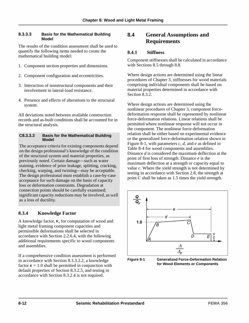
Chapter 8: Wood and Light Metal Framing
8.3.3.3 Basis for the Mathematical Building Model
The results of the condition assessment shall be used to quantify the following items needed to create the mathematical building model:
1. Component section properties and dimensions.
2. Component configuration and eccentricities.
3. Interaction of nonstructural components and their involvement in lateral-load resistance.
4. Presence and effects of alterations to the structural system.
All deviations noted between available construction records and as-built conditions shall be accounted for in the structural analysis.
8.3.4 Knowledge Factor
A knowledge factor, κ, for computation of wood and light metal framing component capacities and permissible deformations shall be selected in accordance with Section 2.2.6.4, with the following additional requirements specific to wood components and assemblies.
If a comprehensive condition assessment is performed in accordance with Section 8.3.3.2.2, a knowledge factor κ = 1.0 shall be permitted in conjunction with default properties of Section 8.3.2.5, and testing in accordance with Section 8.3.2.4 is not required.
8.4 General Assumptions and Requirements
8.4.1 Stiffness
Component stiffnesses shall be calculated in accordance with Sections 8.5 through 8.8.
Where design actions are determined using the linear procedures of Chapter 3, stiffnesses for wood materials comprising individual components shall be based on material properties determined in accordance with Section 8.3.2.
Where design actions are determined using the nonlinear procedures of Chapter 3, component force-deformation response shall be represented by nonlinear force-deformation relations. Linear relations shall be permitted where nonlinear response will not occur in the component. The nonlinear force-deformation relation shall be either based on experimental evidence or the generalized force-deformation relation shown in Figure 8-1, with parameters c, d, and e as defined in Table 8-4 for wood components and assemblies. Distance d is considered the maximum deflection at the point of first loss of strength. Distance e is the maximum deflection at a strength or capacity equal to value c. Where the yield strength is not determined by testing in accordance with Section 2.8, the strength at point C shall be taken as 1.5 times the yield strength.
C8.3.3.3 Basis for the Mathematical Building Model
The acceptance criteria for existing components depend on the design professional’s knowledge of the condition of the structural system and material properties, as previously noted. Certain damage—such as water staining, evidence of prior leakage, splitting, cracking, checking, warping, and twisting—may be acceptable. The design professional must establish a case-by-case acceptance for such damage on the basis of capacity loss or deformation constraints. Degradation at connection points should be carefully examined; significant capacity reductions may be involved, as well as a loss of ductility.
Figure 8-1 Generalized Force-Deformation Relation for Wood Elements or Components
8-12 Seismic Rehabilitation Prestandard FEMA 356
Chapter 8: Wood and Light Metal Framing
8.4.2 Strength and Acceptance Criteria
8.4.2.1 General
Actions in a structure shall be classified as being either deformation-controlled or force-controlled, as defined in Section 2.4.4. Design strengths for deformation-controlled and force-controlled actions shall be calculated in accordance with Sections 8.4.2.2 and Sections 8.4.2.3, respectively.
8.4.2.2 Deformation-Controlled Actions
Expected strengths for deformation-controlled actions, QCE, shall be taken as yield strengths obtained experimentally or calculated using accepted principles of mechanics. Unless other procedures are specified in this chapter, the expected strengths shall be permitted to be based on the LRFD procedures contained in ASCE 16, except that the resistance factor, φ, shall be taken as unity. Material properties shall be determined in accordance with Section 8.3.2. Acceptance criteria for deformation-controlled actions shall be as specified in Sections 8.5 through 8.8.
8.4.2.3 Force-Controlled Actions
Where obtained by testing, lower-bound strengths for force-controlled actions, QCL, shall be taken as the mean minus one standard deviation of yield strengths. Where calculated using established principles of mechanics or based on LRFD procedures contained in ASCE 16, lower-bound strength values shall be determined using the default lower bound material properties defined in Section 8.3.2.5.
Where the force-controlled design actions, QUF, calculated in accordance with Section 3.4.2.1.2 are based on a limit-state analysis, the expected strength of the components delivering load to the component under consideration shall be taken as 1.5 times the yield strength.
8.4.3 Connection Requirements
Unless otherwise specified in this standard, connections between wood components in a lateral-force-resisting system shall be considered in accordance with this section. Demands on connectors, including nails, screws, lags, bolts, split rings, and shear plates used to link wood components to other wood or metal components, shall be considered deformation-controlled actions. Demands on bodies of connections, and bodies of connection hardware, shall be considered force-controlled actions.
C8.4.2.2 Deformation-Controlled Actions
The relative magnitude of the m-factors alone should not be interpreted as a direct indicator of performance. The stiffness of a component and its expected strength, QCE, must be considered when evaluating expected performance, For example, while the m-factors for gypsum plaster are higher than those for wood structural panels, the stiffness assigned to gypsum plaster is relatively high and the expected strength values are much lower than those for wood structural panels. As a result, worse performance for a given displacement is predicted.
C8.4.2.3 Force-Controlled Actions
The maximum forces developed in yielding shear walls and diaphragms are consistently 1.5 to 2 times the yield force. Other wood components and connectors exhibit similar overstrength.
C8.4.3 Connection Requirements
In considering connections between wood components in this standard, connectors are distinguished from bodies of connections. Connectors, which consist of the nails, screws, lags, bolts, split rings, and shear plates used to link pieces of a connection assembly together, are considered to have the ability to deform in a ductile manner, provided the bodies of the connections do not prematurely fracture. Much of the ductility in a wood shear wall or diaphragm assembly comes from bending in the nails prior to point where nails pull through the sheathing material. In bolted connections, bolt bending or crushing of the wood around the bolt hole are ductile sources of deformation in an assembly, as long as net section fracture or splitting do not occur. For this reason, connectors are considered deformation-controlled and bodies of connections are considered force-controlled. When determining the demand on force-controlled portions of the connection assembly, use of a limit-state analysis to determine the maximum force that can be delivered to the connection is recommended.
FEMA 356 Seismic Rehabilitation Prestandard 8-13

Chapter 8: Wood and Light Metal Framing
8.4.4 Rehabilitation Measures
If portions of a wood building structure are deficient for the selected Rehabilitation Objective, the structure shall be rehabilitated, reinforced, or replaced. If replacement of the element is selected, the new element shall be designed in accordance with an approved building code. If reinforcement of the existing framing system is selected, the following factors shall be considered:
1. Degree of degradation in the component from such mechanisms as biological attack, creep, high static or dynamic loading, moisture, or other effects.
2. Level of steady state stress in the components to be reinforced and the potential to temporarily remove this stress if appropriate.
3. Elastic and inelastic properties of existing components; strain compatibility with any new reinforcement materials shall be preserved.
4. Ductility, durability, and suitability of existing connectors between components, and access for reinforcement or modification.
5. Efforts necessary to achieve appropriate fit-up for reinforcing components and connections.
6. Load path and deformation of the components at end connections.
7. Presence of components manufactured with archaic materials, which may contain material discontinuities and shall be examined during the rehabilitation design to ensure that the selected reinforcement is feasible.
8.5 Wood and Light Frame Shear Walls
8.5.1 General
Wood and light frame shear walls shall be categorized as primary or secondary elements. Walls that are considered part of the lateral-force-resisting system shall be considered primary elements. Walls that are not considered part of the lateral-force-resisting system, but must remain stable to support the gravity loads during seismic excitation, shall be considered secondary elements.
Dissimilar wall sheathing materials on opposite sides of a wall shall not be combined when calculating the capacity of the wall. Different walls sheathed with dissimilar materials along the same line of lateral-force resistance shall be analyzed based on only the wall sheathing with the greatest capacity. The walls shall be analyzed based on the relative rigidity and capacity of the materials to determine if performance of the secondary elements is acceptable.
For overturning calculations on shear wall elements, stability shall be evaluated in accordance with Section 3.2.10. Net tension due to overturning shall be resisted by uplift connections.
When computing the strength of connections, all potential limit states should be considered, including those associated with the bodies of connection hardware or connectors with which the assembly may be composed. For example, in addition to the strength of a hold-down device itself, limit states for the stud bolts, foundation bolts, and net section of the end post should be considered. The controlling condition will determine the expected or lower-bound strength of the connection.
C8.4.4 Rehabilitation Measures
Special attention is required where connections such as bolts and nails are encountered.
Wood structural panels are used to provide lateral strength and stiffness to most modern wood frame buildings and are generally recommended for the rehabilitation of horizontal diaphragms and shear walls of existing buildings. The system relies on the in-plane strength and stiffness of the panels and their connection to the framing. Panels are connected together by nailing into the same structural member to create, in effect, one continuous panel. The various panels are described in Sections 8.5 and 8.6. The performance of the structural panels is dependent to a great degree on the nailing or attachment to the framing. The nail spacing and effectiveness of the attachment should be investigated if the existing panels are expected to withstand significant loads. If nails are to be added to existing panels, they should be the same size as the existing nails.
8-14 Seismic Rehabilitation Prestandard FEMA 356

Chapter 8: Wood and Light Metal Framing
The effects of openings in wood shear walls shall be considered. Where required, reinforcement consisting of chords and collectors shall be added to provide sufficient load capacity around openings to meet the requirements for shear walls.
Connections between shear walls and other components including drag struts, collectors, diaphragms, posts, and foundations shall be considered in accordance with Section 8.4.3, and designed for forces calculated in accordance with Chapter 3. Components supporting discontinuous shear walls shall be considered in accordance with Section 8.8.2.
The expected strength, QCE, of wood and light frame shear walls shall be taken as the yield capacity of the shear wall assembly determined in accordance with Sections 8.5.4 through 8.5.18.
8.5.2 Types of Wood Frame Shear Walls
8.5.2.1 Existing Wood Frame Shear Walls
8.5.2.1.1 Single Layer Horizontal Lumber Sheathing or Siding
Single layer horizontal lumber sheathing or siding shall include horizontal sheathing or siding applied directly to studs or horizontal boards nailed to studs 2 inches or greater in width.
C8.5.1 General
The behavior of wood and light frame shear walls is complex and influenced by many factors, the primary factor being the wall sheathing. Wall sheathings can be divided into many categories (e.g., brittle, elastic, strong, weak, good at dissipating energy, poor at dissipating energy). In many existing buildings, the walls were not expected to act as shear walls (e.g., a wall sheathed with wood lath and plaster). Most shear walls are designed based on values from monotonic load tests and historically accepted values. The allowable shear per unit length used for design was assumed to be the same for long walls, narrow walls, walls with stiff tie-downs, and walls with flexible tie- downs. Only recently have shear wall assemblies—framing, covering, anchorage—been tested using cyclic loading.
Another major factor influencing the behavior of shear walls is the aspect ratio of the wall. The NEHRP Recommended Provisions (BSSC, 2000) limit the aspect ratio (height-to-width) for structural panel shear walls to 2:1 for full design shear capacity and permit reduced design shear capacities for walls with aspect ratios up to 3.5:1. The interaction of the floor and roof with the wall, the end conditions of the wall, and the redundancy or number of walls along any wall line would affect the wall behavior for walls with the same aspect ratio. In addition, the rigidity of the tie-downs at the wall ends has an important effect in the behavior of narrow walls.
The presence of any but small openings in wood shear walls will cause a reduction in the stiffness and yield capacity due to a reduced length of wall available to resist lateral forces. Special analysis techniques and detailing are required at the openings. The presence or addition of chord members around the openings will reduce the loss in overall stiffness and limit damage in the area of openings. See BSSC (2000) for reinforcement requirements around openings in wood shear walls.
For wood and light frame shear walls, the important limit states are sheathing failure, connection failure, tie-down failure, and excessive deflection. Limit states define the point of life safety and, often, of structural stability. To reduce damage or retain usability immediately after an earthquake, deflection must be limited (see Section 2.5). The ultimate capacity is the maximum capacity of the assembly, regardless of the deflection.
C8.5.2.1.1 Single Layer Horizontal Lumber Sheathing or Siding
Typically, 1"x horizontal sheathing or siding is applied directly to studs. Forces are resisted by nail couples. Horizontal boards, from 1" x 4" to 1" x 12", typically are nailed to 2"x or greater width studs with two or more nails (typically 8d or 10d) per stud.
FEMA 356 Seismic Rehabilitation Prestandard 8-15

Chapter 8: Wood and Light Metal Framing
8.5.2.1.2 Diagonal Lumber Sheathing
Diagonal lumber sheathing shall include sheathing applied at a 45-degree angle to the studs in a single or double layer with three or more nails per stud, sill and top plates.
8.5.2.1.3 Vertical Wood Siding Only
Vertical wood siding shall include vertical boards nailed directly to studs and blocking 2 inches or greater in width.
8.5.2.1.4 Wood Siding over Horizontal Sheathing
Wood siding over horizontal sheathing shall include siding connected to horizontal sheathing with nails that go through the sheathing to the studs.
8.5.2.1.5 Wood Siding over Diagonal Sheathing
Wood siding over diagonal sheathing shall include siding connected to diagonal sheathing with nails that go through the sheathing to the studs.
8.5.2.1.6 Wood Structural Panel Sheathing or Siding
Wood structural panel sheathing or siding shall include wood structural panels, as defined in this standard, oriented vertically or horizontally and nailed to studs 2 inches or greater in width.
8.5.2.1.7 Stucco on Studs
Stucco on studs (over sheathing or wire-backed building paper) shall include portland cement plaster applied to wire lath or expanded metal lath. Wire lath or expanded metal lath shall be nailed to the studs.
8.5.2.1.8 Gypsum Plaster on Wood Lath
Gypsum plaster on wood lath shall include gypsum plaster keyed onto spaced wood lath that is nailed to the studs.
C8.5.2.1.2 Diagonal Lumber Sheathing
Typically, 1" x 6" or 1" x 8" diagonal sheathing, applied directly to the studs, resists lateral forces primarily by triangulation (i.e., direct tension and compression). Sheathing boards are installed at a 45-degree angle to studs, with three or more nails (typically 8d or 10d) per stud, and to sill and top plates. A second layer of diagonal sheathing is sometimes added on top of the first layer, at 90 degrees to the first layer (called Double Diagonal Sheathing), for increased load capacity and stiffness.
C8.5.2.1.3 Vertical Wood Siding Only
Typically, 1" x 8", 1" x 10", or 1" x 12" vertical boards are nailed directly to 2"x or greater width studs and blocking with 8d or 10d galvanized nails. The lateral forces are resisted by nail couples, similarly to horizontal siding.
C8.5.2.1.4 Wood Siding over Horizontal Sheathing
Typically, siding is nailed with 8d or 10d galvanized nails through the sheathing to the studs. Lateral forces are resisted by nail couples for both layers.
C8.5.2.1.5 Wood Siding over Diagonal Sheathing
Typically, siding is nailed with 8d or 10d galvanized nails to and through the sheathing into the studs. Diagonal sheathing provides most of the lateral resistance by triangulation (see Section 8.5.2.1.2).
C8.5.2.1.6 Wood Structural Panel Sheathing or Siding
Typically, 4′ x 8′ panels are applied vertically or horizontally to 2"x or greater studs and nailed with 6d to 10d nails. These panels resist lateral forces by panel diaphragm action.
C8.5.2.1.7 Stucco on Studs
Typically, 7/8-inch portland cement plaster is applied to wire lath or expanded metal lath. Wire lath or expanded metal lath is nailed to the studs with 11 gage nails or 16 gage staples at 6 inches on center. This assembly resists lateral forces by panel diaphragm action.
C8.5.2.1.8 Gypsum Plaster on Wood Lath
Typically, 1-inch gypsum plaster is keyed onto spaced 1-1/4-inch wood lath that is nailed to studs with 13 gage nails. Gypsum plaster on wood lath resists lateral forces by panel diaphragm-shear action.
8-16 Seismic Rehabilitation Prestandard FEMA 356
Chapter 8: Wood and Light Metal Framing
8.5.2.1.9 Gypsum Plaster on Gypsum Lath
Gypsum plaster on gypsum lath shall include plaster that is glued or keyed to gypsum lath nailed to studs.
8.5.2.1.10 Gypsum Wallboard or Drywall
Gypsum wallboard or drywall shall include manufactured panels with a paper facing and gypsum core that are oriented horizontally or vertically and nailed to studs or blocking in a single layer or multiple layers.
8.5.2.1.11 Gypsum Sheathing
Gypsum sheathing shall include manufactured gypsum panels that are oriented horizontally or vertically and nailed to studs or blocking.
8.5.2.1.12 Plaster on Metal Lath
Plaster on metal lath shall include gypsum plaster applied to expanded wire lath that is nailed to the studs.
8.5.2.1.13 Horizontal Lumber Sheathing with Cut-In Braces or Diagonal Blocking
Horizontal lumber sheathing with cut-in braces or diagonal blocking shall include 1"x horizontal sheathing or siding applied directly to studs or 1" x 4" to 1" x 12" horizontal boards nailed to studs 2 inches or greater in width. The wall shall be braced with diagonal cut-in braces or blocking extending from corner to corner.
8.5.2.1.14 Fiberboard or Particleboard Sheathing
Fiberboard or particleboard sheathing walls shall include fiberboard or particleboard panels that are applied directly to the studs with nails.
8.5.2.2 Enhanced Wood Frame Shear Walls
Enhanced wood frame shear walls shall include existing shear walls rehabilitated in accordance with an approved method. Enhanced wood shear walls shall be evaluated in accordance with Section 8.5.9.
C8.5.2.1.9 Gypsum Plaster on Gypsum Lath
Typically, 1/2-inch plaster is glued or keyed to 16" x 48" gypsum lath, which is nailed to studs with 13 gage nails. Gypsum plaster on gypsum lath resists lateral loads by panel diaphragm action.
C8.5.2.1.10 Gypsum Wallboard or Drywall
Typically, 4′x 8′ to 4′ x 12′ panels are laid-up horizontally or vertically and nailed to studs or blocking with 5d to 8d cooler nails at 4 to 7 inches on center. Multiple layers are used in some situations. The assembly resists lateral forces by panel diaphragm action.
C8.5.2.1.11 Gypsum Sheathing
Typically, 4′ x 8′ to 4′ x 12′ panels are laid-up horizontally or vertically and nailed to studs or blocking with galvanized 11 gage 7/16-inch diameter head nails at 4 to 7 inches on center. Gypsum sheathing is usually installed on the exterior of structures with siding over it in order to improve fire resistance. Lateral forces are resisted by panel diaphragm action.
C8.5.2.1.12 Plaster on Metal Lath
Typically, 1-inch gypsum plaster is applied on expanded wire lath that is nailed to the studs. Lateral forces are resisted by panel diaphragm action.
C8.5.2.1.13 Horizontal Lumber Sheathing with Cut-In Braces or Diagonal Blocking
Horizontal sheathing with cut-in braces or diagonal blocking is installed in the same manner as horizontal sheathing, except the wall is braced with cut-in (or let-in) braces or blocking. The bracing is usually installed at a 45-degree angle and nailed with 8d or 10d nails at each stud, and at the top and bottom plates. Bracing provides only nominal increase in resistance.
C8.5.2.1.14 Fiberboard or Particleboard Sheathing
Typically, 4′ x 8′ panels are applied directly to the studs with nails. Fiberboard requires nails (typically 8d) with large heads such as roofing nails. Lateral loads are resisted by panel diaphragm action.
C8.5.2.2 Enhanced Wood Frame Shear Walls
Possible rehabilitation methods for wood shear walls are described in Sections C8.5.2.2.1 through C8.5.2.2.5.
C8.5.2.2.1 Wood Structural Panel Sheathing Added to Unfinished Stud Walls
Wood structural panel sheathing may be added to one side of unfinished stud walls to increase the wall shear capacity and stiffness.
FEMA 356 Seismic Rehabilitation Prestandard 8-17
Chapter 8: Wood and Light Metal Framing
Examples of unfinished stud walls are cripple walls and attic end walls.
C8.5.2.2.2 Wood Structural Panel Sheathing Overlay of Existing Shear Walls
The following types of existing shear walls may be overlaid with wood structural panel sheathing:
1. Single layer horizontal lumber sheathing or siding.
2. Single layer diagonal lumber sheathing.
3. Vertical wood siding only.
4. Gypsum plaster or wallboard on studs (also on gypsum lath and gypsum wallboard).
5. Gypsum sheathing.
6. Horizontal lumber sheathing with cut-in braces or diagonal blocking.
7. Fiberboard or particleboard sheathing.
The original sheathing should not be included in the evaluation conducted in accordance with Section 8.5.9 and the yield capacity of the overlay material should be reduced by 20%.
This method results in a moderate increase in shear capacity and stiffness and can be applied in most places in most structures. For example, plywood sheathing can be applied over an interior wall finish. For exterior applications, the wood structural panel can be nailed directly through the exterior finish to the studs.
When existing shear walls are overlaid with wood structural panels, the connections of the overlay to the existing framing must be considered. Splitting can occur in both the wood sheathing and the framing. The length of nails needed to achieve full capacity attachment in the existing framing must be determined. This length will vary with the thickness of the existing wall covering. Sometimes staples are used instead of nails to prevent splitting. The overlay is stapled to the wood sheathing instead of the framing. Nails are recommended for overlay attachment to the underlying framing. In some cases, new blocking at wood structural panel joints may also be needed.
C8.5.2.2.3 Wood Structural Panel Sheathing Added under Existing Wall Covering
The existing wall covering may be removed; wood structural panel sheathing, connections, and tie-downs may be added; and the wall covering may be replaced.
This method will result in a significant increase in shear capacity. In some cases, where earthquake loads are large, this may be the best method of rehabilitation. This rehabilitation procedure can be used on any of the existing shear wall assemblies. Additional framing members can be added if necessary, and the wood structural panels can be cut to fit existing stud spacings.
C8.5.2.2.4 Increased Attachment
Additional nailing, collector straps, splice straps, tie-downs or other collectors may be added to existing wood structural panel-sheathed walls to increase their rigidity and capacity.
For existing structural panel-sheathed walls, additional nailing will result in higher capacity and increased stiffness. Other connectors—collector straps, splice straps, or tie-downs—are often necessary to increase the rigidity and capacity of existing structural panel shear walls. Increased ductility will not necessarily result from the additional nailing. Access to these shear walls will often require the removal and replacement of existing finishes.
C8.5.2.2.5 Connections
Where absent, new connections between shear walls and diaphragms and foundations may be added. Where needed, blocking between floor and roof joists at shear walls may be added. Blocking should be connected to the shear wall and the diaphragm to provide a load path for lateral loads. Wood for framing members or blocking should be kiln-dried or well-seasoned to prevent it from shrinking away from the existing framing, or splitting.
Most shear wall rehabilitation procedures require a check of all existing connections, especially to diaphragms and foundations. Sheet metal framing clips can be used to provide a verifiable connection between the wall framing, the blocking, and the diaphragm. Framing clips are also often used for connecting blocking or rim joists to sill plates.
Frequently, bolting between sill plates and foundations must be added.
8-18 Seismic Rehabilitation Prestandard FEMA 356

Chapter 8: Wood and Light Metal Framing
8.5.2.3 New Wood Frame Shear Walls
New wood frame shear walls shall include all new wood structural panel shear walls added to an existing lateral-force-resisting system. Design of new walls shall be in accordance with the requirements of an approved building code.
8.5.3 Types of Light Gage Metal Frame Shear Walls
8.5.3.1 Existing Light Gage Metal Frame Shear Walls
8.5.3.1.1 Plaster on Metal Lath
Plaster on metal lath shall include gypsum plaster applied to metal lath or expanded metal lath that is connected to the metal framing with wire ties.
8.5.3.1.2 Gypsum Wallboard
Gypsum wallboard shear walls shall include gypsum wallboard panels that are attached to the studs.
8.5.3.1.3 Wood Structural Panel Sheathing or Siding
Wood structural panel shear walls shall include structural panels that are attached to the studs and tracks.
8.5.3.2 Enhanced Light Gage Metal Frame Shear Walls
Enhanced light gage metal frame shear walls shall include existing shear walls rehabilitated in accordance with an approved method.
The framing in existing buildings is usually very dry, hard, and easily split. Care must be taken not to split the existing framing when adding connectors. Predrilling holes for nails will reduce splitting, and framing clips that use small nails are less likely to split the existing framing.
C8.5.2.3 New Wood Frame Shear Walls
New shear walls using the existing framing or new framing generally are sheathed with wood structural panels (i.e., plywood or oriented strand board). According to the NEHRP Recommended Provisions (BSSC, 2000), only wood structural panel sheathing is permitted for use in wood frame shear walls in engineered construction. The thickness and grade of these panels can vary. In most cases, the panels are placed vertically and fastened directly to the studs and plates. This reduces the need for blocking at the joints. All edges of panels must be blocked to obtain full capacity. The thickness, size, and number of fasteners, and aspect ratio and connections will determine the capacity of the new walls. Additional information on the various panels available and their application for shear walls can be found in documents from the American Plywood Association (APA) such as APA (1995 and 1997) and Tissell (1993).
C8.5.3.1.1 Plaster on Metal Lath
Typically, 1 inch of gypsum plaster is applied to metal lath or expanded metal that is connected to the metal framing with wire ties.
C8.5.3.1.2 Gypsum Wallboard
Typically, 4′ x 8′ to 4′ x 12′ panels are laid-up horizontally and screwed with No. 6 x 1-inch-long self-tapping screws to studs at 4 to 7 inches on center.
C8.5.3.1.3 Wood Structural Panel Sheathing or Siding
Typically, the wood structural panels are applied vertically and screwed to the studs and tracks with No. 8 to No. 12 self-tapping screws.
C8.5.3.2 Enhanced Light Gage Metal Frame Shear Walls
Possible rehabilitation methods for light gage metal frame shear walls are described in Sections C8.5.3.2.1 and C8.5.3.2.2. See Section 8.5.2.2 for additional information concerning enhancement of existing shear walls.
C8.5.3.2.1 Wood Structural Panel Sheathing Added to Existing Metal Stud Walls
Any existing covering other than wood structural panels shall be removed and replaced with wood structural panels. Connections to the diaphragm(s) and the foundation shall be checked and strengthened when not adequate to resist enhanced wall capacity.
C8.5.3.2.2 Increased Attachment
Screws and connections shall be added to connect existing wood structural panels to framing.
FEMA 356 Seismic Rehabilitation Prestandard 8-19
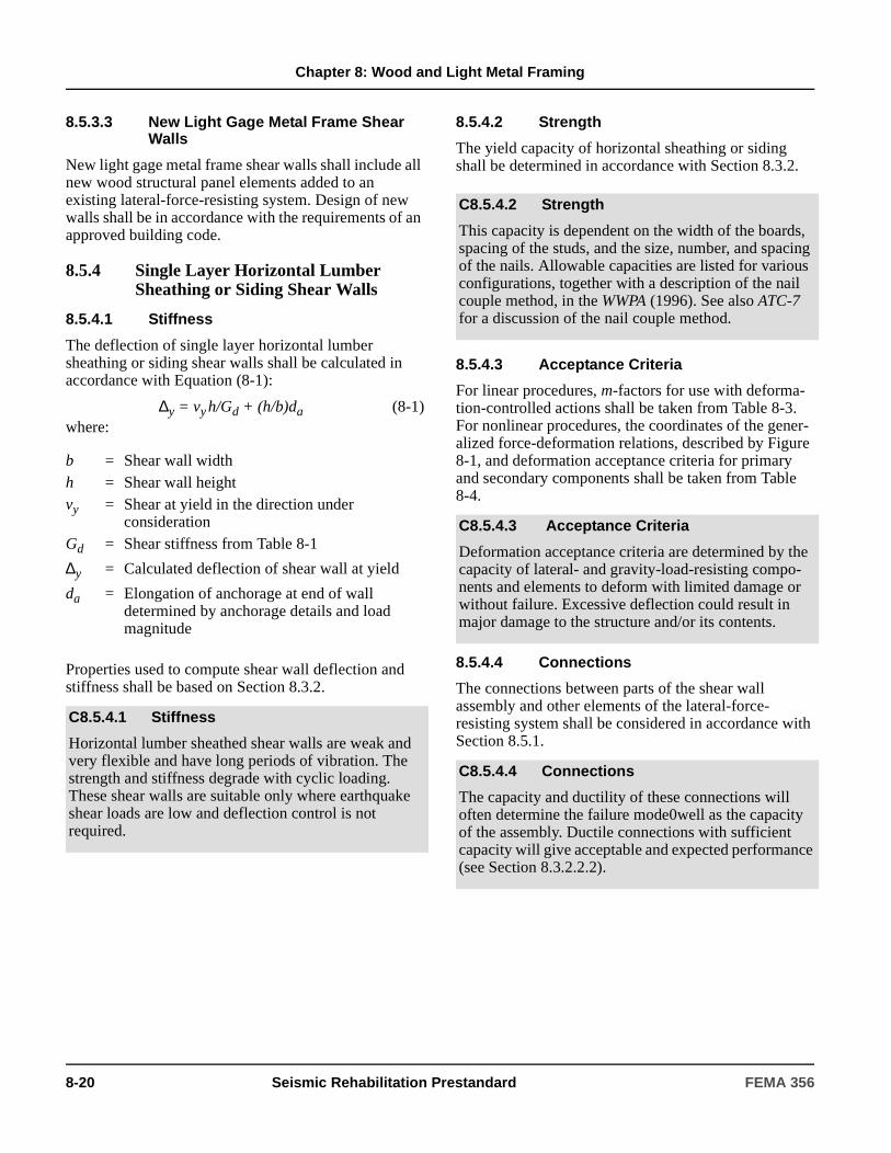
Chapter 8: Wood and Light Metal Framing
8.5.3.3 New Light Gage Metal Frame Shear Walls
New light gage metal frame shear walls shall include all new wood structural panel elements added to an existing lateral-force-resisting system. Design of new walls shall be in accordance with the requirements of an approved building code.
8.5.4 Single Layer Horizontal Lumber Sheathing or Siding Shear Walls
8.5.4.1 Stiffness
The deflection of single layer horizontal lumber sheathing or siding shear walls shall be calculated in accordance with Equation (8-1):
∆y = vy h/Gd + (h/b)da (8-1)where:
Properties used to compute shear wall deflection and stiffness shall be based on Section 8.3.2.
8.5.4.2 Strength
The yield capacity of horizontal sheathing or siding shall be determined in accordance with Section 8.3.2.
8.5.4.3 Acceptance Criteria
For linear procedures, m-factors for use with deforma-tion-controlled actions shall be taken from Table 8-3. For nonlinear procedures, the coordinates of the gener-alized force-deformation relations, described by Figure 8-1, and deformation acceptance criteria for primary and secondary components shall be taken from Table 8-4.
8.5.4.4 Connections
The connections between parts of the shear wall assembly and other elements of the lateral-force-resisting system shall be considered in accordance with Section 8.5.1.
b = Shear wall widthh = Shear wall heightvy = Shear at yield in the direction under
considerationGd = Shear stiffness from Table 8-1
∆y = Calculated deflection of shear wall at yield
da = Elongation of anchorage at end of wall determined by anchorage details and load magnitude
C8.5.4.1 Stiffness
Horizontal lumber sheathed shear walls are weak and very flexible and have long periods of vibration. The strength and stiffness degrade with cyclic loading. These shear walls are suitable only where earthquake shear loads are low and deflection control is not required.
C8.5.4.2 Strength
This capacity is dependent on the width of the boards, spacing of the studs, and the size, number, and spacing of the nails. Allowable capacities are listed for various configurations, together with a description of the nail couple method, in the WWPA (1996). See also ATC-7 for a discussion of the nail couple method.
C8.5.4.3 Acceptance Criteria
Deformation acceptance criteria are determined by the capacity of lateral- and gravity-load-resisting compo-nents and elements to deform with limited damage or without failure. Excessive deflection could result in major damage to the structure and/or its contents.
C8.5.4.4 Connections
The capacity and ductility of these connections will often determine the failure mode0well as the capacity of the assembly. Ductile connections with sufficient capacity will give acceptable and expected performance (see Section 8.3.2.2.2).
8-20 Seismic Rehabilitation Prestandard FEMA 356
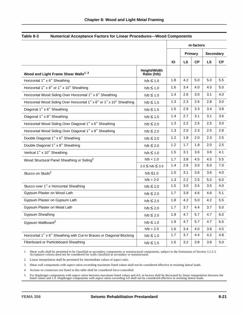
Chapter 8: Wood and Light Metal Framing
Table 8-3 Numerical Acceptance Factors for Linear Procedures—Wood Components
m-factors
IO
Primary Secondary
LS CP LS CP
Wood and Light Frame Shear Walls1, 3Height/Width
Ratio (h/b)
Horizontal 1" x 6" Sheathing h/b ≤ 1.0 1.8 4.2 5.0 5.0 5.5
Horizontal 1" x 8" or 1" x 10" Sheathing h/b ≤ 1.0 1.6 3.4 4.0 4.0 5.0
Horizontal Wood Siding Over Horizontal 1" x 6" Sheathing h/b ≤ 1.0 1.4 2.6 3.0 3.1 4.0
Horizontal Wood Siding Over Horizontal 1" x 8" or 1" x 10" Sheathing h/b ≤ 1.5 1.3 2.3 2.6 2.8 3.0
Diagonal 1" x 6" Sheathing h/b ≤ 1.5 1.5 2.9 3.3 3.4 3.8
Diagonal 1" x 8" Sheathing h/b ≤ 1.5 1.4 2.7 3.1 3.1 3.6
Horizontal Wood Siding Over Diagonal 1" x 6" Sheathing h/b ≤ 2.0 1.3 2.2 2.5 2.5 3.0
Horizontal Wood Siding Over Diagonal 1" x 8" Sheathing h/b ≤ 2.0 1.3 2.0 2.3 2.5 2.8
Double Diagonal 1" x 6" Sheathing h/b ≤ 2.0 1.2 1.8 2.0 2.3 2.5
Double Diagonal 1" x 8" Sheathing h/b ≤ 2.0 1.2 1.7 1.9 2.0 2.5
Vertical 1" x 10" Sheathing h/b ≤ 1.0 1.5 3.1 3.6 3.6 4.1
Wood Structural Panel Sheathing or Siding2 h/b < 1.0 1.7 3.8 4.5 4.5 5.5
2.0 ≤ h/b ≤ 3.5 1.4 2.6 3.0 6.0 7.0
Stucco on Studs2 h/b ≤1.0 1.5 3.1 3.6 3.6 4.0
h/b = 2.0 1.3 2.2 2.5 5.0 6.0
Stucco over 1"-x Horizontal Sheathing h/b ≤ 2.0 1.5 3.0 3.5 3.5 4.0
Gypsum Plaster on Wood Lath h/b ≤ 2.0 1.7 3.9 4.6 4.6 5.1
Gypsum Plaster on Gypsum Lath h/b ≤ 2.0 1.8 4.2 5.0 4.2 5.5
Gypsum Plaster on Metal Lath h/b ≤ 2.0 1.7 3.7 4.4 3.7 5.0
Gypsum Sheathing h/b ≤ 2.0 1.9 4.7 5.7 4.7 6.0
Gypsum Wallboard2 h/b ≤ 1.0 1.9 4.7 5.7 4.7 6.0
h/b = 2.0 1.6 3.4 4.0 3.8 4.5
Horizontal 1" x 6" Sheathing with Cut-In Braces or Diagonal Blocking h/b ≤ 1.0 1.7 3.7 4.4 4.2 4.8
Fiberboard or Particleboard Sheathing h/b ≤ 1.5 1.6 3.2 3.8 3.8 5.0
1. Shear walls shall be permitted to be classified as secondary components or nonstructural components, subject to the limitations of Section 3.2.2.3. Acceptance criteria need not be considered for walls classified as secondary or nonstructural.
2. Linear interpolation shall be permitted for intermediate values of aspect ratio.
3. Shear wall components with aspect ratios exceeding maximum listed values shall not be considered effective in resisting lateral loads.
4. Actions on connectors not listed in this table shall be considered force-controlled.
5. For diaphragm components with aspect ratios between maximum listed values and 4.0, m-factors shall be decreased by linear interpolation between the listed values and 1.0. Diaphragm components with aspect ratios exceeding 4.0 shall not be considered effective in resisting lateral loads.
FEMA 356 Seismic Rehabilitation Prestandard 8-21

Chapter 8: Wood and Light Metal Framing
Diaphragms5Length/WidthRatio (L/b)
Single Straight Sheathing, Chorded L/b ≤ 3.0 1 2.0 2.5 2.4 3.1
Single Straight Sheathing, Unchorded L/b ≤ 3.0 1 1.5 2.0 1.8 2.5
Double Straight Sheathing, Chorded L/b ≤ 3.0 1.25 2.0 2.5 2.3 2.8
Double Straight Sheathing, Unchorded L/b ≤ 3.0 1 1.5 2.0 1.8 2.3
Single Diagonal Sheathing, Chorded L/b ≤ 3.0 1.25 2.0 2.5 2.3 2.9
Single Diagonal Sheathing, Unchorded L/b ≤ 3.0 1 1.5 2.0 1.8 2.5
Straight Sheathing Over Diagonal Sheathing, Chorded L/b ≤ 3.0 1.5 2.5 3.0 2.8 3.5
Straight Sheathing Over Diagonal Sheathing, Unchorded L/b ≤ 3.0 1.25 2.0 2.5 2.3 3.0
Double Diagonal Sheathing, Chorded L/b ≤ 3.5 1.5 2.5 3.0 2.9 3.5
Double Diagonal Sheathing, Unchorded L/b ≤ 3.5 125 2.0 2.5 2.4 3.1
Wood Structural Panel, Blocked, Chorded2 L/b ≤ 3.0 1.5 3.0 4.0 3.0 4.5
L/b = 4 1.5 2.5 3.0 2.8 3.5
Wood Structural Panel, Unblocked, Chorded2 L/b ≤ 3 1.5 2.5 3.0 2.9 4.0
L/b = 4 1.5 2.0 2.5 2.6 3.2
Wood Structural Panel, Blocked, Unchorded2 L/b ≤ 2.5 1.25 2.5 3.0 2.9 4.0
L/b = 3.5 1.25 2.0 2.5 2.6 3.2
Wood Structural Panel, Unblocked, Unchorded2 L/b ≤ 2.5 1.25 2.0 2.5 2.4 3.0
L/b = 3.5 1.0 1.5 2.0 2.0 2.6
Wood Structural Panel Overlay on Sheathing, Chorded2 L/b ≤ 3 1.5 2.5 3.0 2.9 4.0
L/b = 4 1.5 2.0 2.5 2.6 3.2
Wood Structural Panel Overlay on Sheathing, Unchorded2 L/b ≤ 2.5 1.25 2.0 2.5 2.4 3.0
L/b = 3.5 1.0 1.5 2.0 1.9 2.6
Table 8-3 Numerical Acceptance Factors for Linear Procedures—Wood Components (continued)
m-factors
IO
Primary Secondary
LS CP LS CP
1. Shear walls shall be permitted to be classified as secondary components or nonstructural components, subject to the limitations of Section 3.2.2.3. Acceptance criteria need not be considered for walls classified as secondary or nonstructural.
2. Linear interpolation shall be permitted for intermediate values of aspect ratio.
3. Shear wall components with aspect ratios exceeding maximum listed values shall not be considered effective in resisting lateral loads.
4. Actions on connectors not listed in this table shall be considered force-controlled.
5. For diaphragm components with aspect ratios between maximum listed values and 4.0, m-factors shall be decreased by linear interpolation between the listed values and 1.0. Diaphragm components with aspect ratios exceeding 4.0 shall not be considered effective in resisting lateral loads.
8-22 Seismic Rehabilitation Prestandard FEMA 356
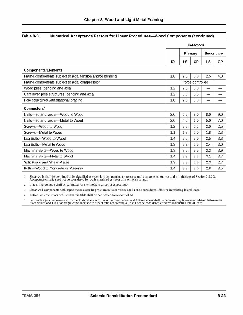
Chapter 8: Wood and Light Metal Framing
Components/Elements
Frame components subject to axial tension and/or bending 1.0 2.5 3.0 2.5 4.0
Frame components subject to axial compression force-controlled
Wood piles, bending and axial 1.2 2.5 3.0 — —
Cantilever pole structures, bending and axial 1.2 3.0 3.5 — —
Pole structures with diagonal bracing 1.0 2.5 3.0 — —
Connectors4
Nails—8d and larger—Wood to Wood 2.0 6.0 8.0 8.0 9.0
Nails—8d and larger—Metal to Wood 2.0 4.0 6.0 5.0 7.0
Screws—Wood to Wood 1.2 2.0 2.2 2.0 2.5
Screws—Metal to Wood 1.1 1.8 2.0 1.8 2.3
Lag Bolts—Wood to Wood 1.4 2.5 3.0 2.5 3.3
Lag Bolts—Metal to Wood 1.3 2.3 2.5 2.4 3.0
Machine Bolts—Wood to Wood 1.3 3.0 3.5 3.3 3.9
Machine Bolts—Metal to Wood 1.4 2.8 3.3 3.1 3.7
Split Rings and Shear Plates 1.3 2.2 2.5 2.3 2.7
Bolts—Wood to Concrete or Masonry 1.4 2.7 3.0 2.8 3.5
Table 8-3 Numerical Acceptance Factors for Linear Procedures—Wood Components (continued)
m-factors
IO
Primary Secondary
LS CP LS CP
1. Shear walls shall be permitted to be classified as secondary components or nonstructural components, subject to the limitations of Section 3.2.2.3. Acceptance criteria need not be considered for walls classified as secondary or nonstructural.
2. Linear interpolation shall be permitted for intermediate values of aspect ratio.
3. Shear wall components with aspect ratios exceeding maximum listed values shall not be considered effective in resisting lateral loads.
4. Actions on connectors not listed in this table shall be considered force-controlled.
5. For diaphragm components with aspect ratios between maximum listed values and 4.0, m-factors shall be decreased by linear interpolation between the listed values and 1.0. Diaphragm components with aspect ratios exceeding 4.0 shall not be considered effective in resisting lateral loads.
FEMA 356 Seismic Rehabilitation Prestandard 8-23

Chapter 8: Wood and Light Metal Framing
Table 8-4 Modeling Parameters and Numerical Acceptance Criteria for Nonlinear Procedures—Wood Components
Modeling Parameters Acceptance Criteria
Residual Strength
Ratio
Acceptable Deformation Ratio ∆ / ∆y
Performance Level
IO
Component Type
Primary Secondary
d e c LS CP LS CP
Wood and Light Frame Shear Walls1
Height/WidthRatio (h/b)
Horizontal 1" x 6" Sheathing h/b ≤ 1.0 5.0 6.0 0.3 2.0 4.0 5.0 5.0 6.0
Horizontal 1" x 8" or 1" x 10" Sheathing
h/b ≤ 1.0 4.0 5.0 0.3 1.8 3.3 4.0 4.0 5.0
Horizontal Wood Siding Over Horizontal 1" x 6" Sheathing
h/b ≤ 1.5 3.0 4.0 0.2 1.5 2.5 3.0 3.0 4.0
Horizontal Wood Siding Over Horizontal 1" x 8" or 1" x 10" Sheathing
h/b ≤ 1.5 2.6 3.6 0.2 1.4 2.2 2.6 2.6 3.6
Diagonal 1" x 6" Sheathing h/b ≤ 1.5 3.3 4.0 0.2 1.6 2.7 3.3 3.3 4.0
Diagonal 1" x 8" Sheathing h/b ≤ 1.5 3.1 4.0 0.2 1.5 2.6 3.1 3.1 4.0
Horizontal Wood Siding Over Diagonal 1" x 6" Sheathing
h/b ≤ 2.0 2.5 3.0 0.2 1.4 2.1 2.5 2.5 3.0
Horizontal Wood Siding Over Diagonal 1" x 8" Sheathing
h/b ≤ 2.0 2.3 3.0 0.2 1.3 2.0 2.3 2.3 3.0
Double Diagonal 1" x 6" Sheathing
h/b ≤ 2.0 2.0 2.5 0.2 1.3 1.8 2.0 2.0 2.5
Double Diagonal 1" x 8" Sheathing
h/b ≤ 2.0 2.0 2.5 0.2 1.3 1.8 2.0 2.0 2.5
Vertical 1" x 10" Sheathing h/b ≤ 1.0 3.6 4.0 0.3 1.7 3.0 3.6 3.6 4.0
Wood Structural Panel Sheathing or Siding2
h/b ≤ 1.0 4.5 5.5 0.3 1.9 3.6 4.5 4.5 5.5
2.0 ≤ h/b ≤ 3.5 3.0 4.0 0.2 1.5 2.5 3.0 3.0 4.0
Stucco on Studs2 h/b ≤ 1.0 3.6 4.0 0.2 1.7 3.0 3.6 3.6 4.0
h/b = 2.0 2.5 3.0 0.2 1.4 2.1 2.5 2.5 3.0
Stucco Over 1"x Horizontal Sheathing
h/b ≤ 2.0 3.5 4.0 0.2 1.6 2.9 3.5 3.5 4.0
Gypsum Plaster on Wood Lath h/b ≤ 2.0 4.6 5.0 0.2 1.9 3.7 4.6 4.6 5.0
Gypsum Plaster on Gypsum Lath h/b ≤ 2.0 5.0 6.0 0.2 2.0 4.0 5.0 5.0 6.0
1. Shear wall components with aspect ratios exceeding maximum listed values shall not be considered effective in resisting lateral loads.
2. Linear interpolation shall be permitted for intermediate values of aspect ratio.
3. For diaphragm components with aspect ratios between maximum listed values and 4.0, deformation ratios shall be decreased by linear interpolation between the listed values and 1.0. Diaphragm components with aspect ratios exceeding 4.0 shall not be considered effective in resisting lateral loads.
4. Actions on connectors not listed in this table shall be considered force-controlled.
∆∆y------
8-24 Seismic Rehabilitation Prestandard FEMA 356

Chapter 8: Wood and Light Metal Framing
Gypsum Plaster on Metal Lath h/b ≤ 2.0 4.4 5.0 0.2 1.9 3.6 4.4 4.4 5.0
Gypsum Sheathing h/b ≤ 2.0 5.7 6.3 0.2 2.2 4.5 5.7 5.7 6.3
Gypsum Wallboard2 h/b ≤ 1.0 5.7 6.3 0.2 2.2 4.5 5.7 5.7 6.3
h/b = 2.0 4.0 5.0 0.2 1.8 3.3 4.0 4.0 5.0
Horizontal 1" x 6" Sheathing with Cut-In Braces or Diagonal Blocking
h/b ≤ 1.0 4.4 5.0 0.2 1.9 3.6 4.4 4.4 5.0
Fiberboard or Particleboard Sheathing
h/b ≤ 1.5 3.8 4.0 0.2 1.7 3.1 3.8 3.8 4.0
Diaphragms3Length/Width
Ratio (L/b)
Single Straight Sheathing, Chorded
L/b ≤ 2.0 2.5 3.5 0.2 1.4 2.1 2.5 2.5 3.5
Single Straight Sheathing, Unchorded
L/b ≤ 2.0 2.0 3.0 0.3 1.3 1.8 2.0 2.0 3.0
Double Straight Sheathing, Chorded
L/b ≤ 2.0 2.5 3.5 0.2 1.4 2.1 2.5 2.5 3.5
Double Straight Sheathing, Unchorded
L/b ≤ 2.0 2.0 3.0 0.3 1.3 1.8 2.0 2.0 3.0
Single Diagonal Sheathing, Chorded
L/b ≤ 2.0 2.5 3.5 0.2 1.4 2.1 2.5 2.5 3.5
Single Diagonal Sheathing, Unchorded
L/b ≤ 2.0 2.0 3.0 0.3 1.3 1.8 2.0 2.0 3.0
Straight Sheathing Over Diagonal Sheathing, Chorded
L/b ≤ 2.0 3.0 4.0 0.2 1.5 2.5 3.0 3.0 4.0
Straight Sheathing Over Diagonal Sheathing, Unchorded
L/b ≤ 2.0 2.5 3.5 0.3 1.4 2.1 2.5 2.5 3.5
Double Diagonal Sheathing, Chorded
L/b ≤ 2.0 3.0 4.0 0.2 1.5 2.5 3.0 3.0 4.0
Double Diagonal Sheathing, Unchorded
L/b ≤ 2.0 2.5 3.5 0.2 1.4 2.1 2.5 2.5 3.5
Table 8-4 Modeling Parameters and Numerical Acceptance Criteria for Nonlinear Procedures—Wood Components (continued)
Modeling Parameters Acceptance Criteria
Residual Strength
Ratio
Acceptable Deformation Ratio ∆ / ∆y
Performance Level
IO
Component Type
Primary Secondary
d e c LS CP LS CP
1. Shear wall components with aspect ratios exceeding maximum listed values shall not be considered effective in resisting lateral loads.
2. Linear interpolation shall be permitted for intermediate values of aspect ratio.
3. For diaphragm components with aspect ratios between maximum listed values and 4.0, deformation ratios shall be decreased by linear interpolation between the listed values and 1.0. Diaphragm components with aspect ratios exceeding 4.0 shall not be considered effective in resisting lateral loads.
4. Actions on connectors not listed in this table shall be considered force-controlled.
∆∆y------
FEMA 356 Seismic Rehabilitation Prestandard 8-25
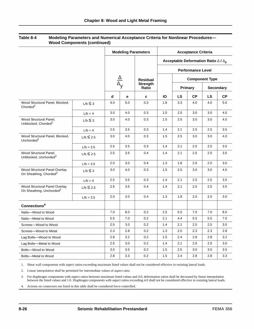
Chapter 8: Wood and Light Metal Framing
Wood Structural Panel, Blocked, Chorded2
L/b ≤ 3 4.0 5.0 0.3 1.8 3.3 4.0 4.0 5.0
L/b = 4 3.0 4.0 0.3 1.5 2.5 3.0 3.0 4.0
Wood Structural Panel, Unblocked, Chorded2
L/b ≤ 3 3.0 4.0 0.3 1.5 2.5 3.0 3.0 4.0
L/b = 4 2.5 3.5 0.3 1.4 2.1 2.5 2.5 3.5
Wood Structural Panel, Blocked, Unchorded2
L/b ≤ 2.5 3.0 4.0 0.3 1.5 2.5 3.0 3.0 4.0
L/b = 3.5 2.5 3.5 0.3 1.4 2.1 2.5 2.5 3.5
Wood Structural Panel, Unblocked, Unchorded2
L/b ≤ 2.5 2.5 3.5 0.4 1.4 2.1 2.5 2.5 3.5
L/b = 3.5 2.0 3.0 0.4 1.3 1.8 2.0 2.0 3.0
Wood Structural Panel Overlay On Sheathing, Chorded2
L/b ≤ 3 3.0 4.0 0.3 1.5 2.5 3.0 3.0 4.0
L/b = 4 2.5 3.5 0.3 1.4 2.1 2.5 2.5 3.5
Wood Structural Panel Overlay On Sheathing, Unchorded2
L/b ≤ 2.5 2.5 3.5 0.4 1.4 2.1 2.5 2.5 3.5
L/b = 3.5 2.0 3.0 0.4 1.3 1.8 2.0 2.0 3.0
Connections4
Nails—Wood to Wood 7.0 8.0 0.2 2.5 5.5 7.0 7.0 8.0
Nails—Metal to Wood 5.5 7.0 0.2 2.1 4.4 5.5 5.5 7.0
Screws—Wood to Wood 2.5 3.0 0.2 1.4 2.1 2.5 2.5 3.0
Screws—Wood to Metal 2.3 2.8 0.2 1.3 2.0 2.3 2.3 2.8
Lag Bolts—Wood to Wood 2.8 3.2 0.2 1.5 2.4 2.8 2.8 3.2
Lag Bolts—Metal to Wood 2.5 3.0 0.2 1.4 2.1 2.5 2.5 3.0
Bolts—Wood to Wood 3.0 3.5 0.2 1.5 2.5 3.0 3.0 3.5
Bolts—Metal to Wood 2.8 3.3 0.2 1.5 2.4 2.8 2.8 3.3
Table 8-4 Modeling Parameters and Numerical Acceptance Criteria for Nonlinear Procedures—Wood Components (continued)
Modeling Parameters Acceptance Criteria
Residual Strength
Ratio
Acceptable Deformation Ratio ∆ / ∆y
Performance Level
IO
Component Type
Primary Secondary
d e c LS CP LS CP
1. Shear wall components with aspect ratios exceeding maximum listed values shall not be considered effective in resisting lateral loads.
2. Linear interpolation shall be permitted for intermediate values of aspect ratio.
3. For diaphragm components with aspect ratios between maximum listed values and 4.0, deformation ratios shall be decreased by linear interpolation between the listed values and 1.0. Diaphragm components with aspect ratios exceeding 4.0 shall not be considered effective in resisting lateral loads.
4. Actions on connectors not listed in this table shall be considered force-controlled.
∆∆y------
8-26 Seismic Rehabilitation Prestandard FEMA 356

Chapter 8: Wood and Light Metal Framing
8.5.5 Diagonal Lumber Sheathing Shear Walls
8.5.5.1 Stiffness
The deflection of diagonal lumber sheathed shear walls shall be determined using Equation (8-1). Properties used to compute shear wall deflection and stiffness shall be based on Section 8.3.2.
8.5.5.2 Strength
The yield capacity of diagonal sheathing shall be determined in accordance with Section 8.3.2.
8.5.5.3 Acceptance Criteria
For linear procedures, m-factors for use with deformation-controlled actions shall be taken from Table 8-3. For nonlinear procedures, the coordinates of the generalized force-deformation relation, described by Figure 8-1, and deformation acceptance criteria for primary and secondary components shall be taken from Table 8-4.
8.5.5.4 Connections
The connections between parts of the shear wall assembly and other elements of the lateral-force-
resisting system shall be considered in accordance with Section 8.5.1.
8.5.6 Vertical Wood Siding Shear Walls
8.5.6.1 Stiffness
The deflection of vertical wood siding shear walls shall be determined using Equation (8-1). Properties used to compute shear wall deflection and stiffness shall be based on Section 8.3.2.
8.5.6.2 Strength
The yield capacity of vertical wood siding shear walls shall be determined in accordance with Section 8.3.2.
8.5.6.3 Acceptance Criteria
For linear procedures, m-factors for use with deformation-controlled actions shall be taken from Table 8-3. For nonlinear procedures, the coordinates of the generalized force-deformation relation, described by Figure 8-1, and deformation acceptance criteria for primary and secondary components shall be taken from Table 8-4.
C8.5.5.1 Stiffness
Diagonal lumber sheathed shear walls are stiffer and stronger than horizontal sheathed shear walls. They also provide greater stiffness for deflection control, and thereby greater damage control.
C8.5.5.2 Strength
The yield capacity of diagonal sheathing is dependent on the width of the boards, the spacing of the studs, the size of nails, the number of nails per board, and the boundary conditions. Allowable capacities are listed for various configurations in WWPA (1996).
C8.5.6.1 Stiffness
Vertical wood siding has a very low lateral-force-resistance capacity and is very flexible. The strength and stiffness degrade with cyclic loading. These shear walls are suitable only where earthquake shear loads are very low and deflection control is not needed.
C8.5.6.2 Strength
The yield capacity of vertical wood siding is dependent on the width of the boards, the spacing of the studs, the spacing of blocking, and the size, number, and spacing of the nails. The nail couple method WWPA (1996) can be used to calculate the capacity of vertical wood siding in a manner similar to the method used for horizontal siding.
FEMA 356 Seismic Rehabilitation Prestandard 8-27
Chapter 8: Wood and Light Metal Framing
8.5.6.4 Connections
The presence of connections between parts of the vertical wood siding shear wall assembly and other elements of the lateral-force-resisting system shall be verified. If connections are present, they need not be considered in the analysis conducted in accordance with Chapter 3. In the absence of connections, connections shall be provided in accordance with Section 8.5.1.
8.5.7 Wood Siding over Horizontal Sheathing Shear Walls
8.5.7.1 Stiffness
The deflection of wood siding over horizontal sheathing shear walls shall be determined using Equation (8-1). Properties used to compute shear wall deflection and stiffness shall be based on Section 8.3.2.
8.5.7.2 Strength
The yield capacity of wood siding over horizontal sheathing shall be determined in accordance with Section 8.3.2.
8.5.7.3 Acceptance Criteria
For linear procedures, m-factors for use with deformation-controlled actions shall be taken from Table 8-3. For nonlinear procedures, the coordinates of the generalized force-deformation relation, described by Figure 8-1, and deformation acceptance criteria for primary and secondary components shall be taken from Table 8-4.
8.5.7.4 Connections
The connections between parts of the shear wall assembly and other elements of the lateral-force-resisting system shall be considered in accordance with Section 8.5.1.
8.5.8 Wood Siding over Diagonal Sheathing
8.5.8.1 Stiffness
The deflection of these shear walls shall be calculated in accordance with Equation (8-1). Properties used to compute shear wall deflection and stiffness shall be based on Section 8.3.2.
8.5.8.2 Strength
The yield capacity of wood siding over diagonal sheathing shall be determined in accordance with Section 8.3.2.
C8.5.6.4 Connections
The load capacity of the vertical siding is low, which makes the capacity of connections between the shear wall and the other elements of less concern (see Section 8.3.2.2.2).
C8.5.7.1 Stiffness
Double-layer horizontal sheathed shear walls are stiffer and stronger than single-layer horizontal sheathed shear walls. These shear walls are often suitable for resisting earthquake shear loads that are low to moderate in magnitude. They also provide greater stiffness for deflection control and, thereby, greater damage control.
C8.5.7.2 Strength
This capacity is dependent on the width of the boards, the spacing of the studs, the size, number, and spacing of the nails, and the location of joints.
C8.5.8.1 Stiffness
Horizontal wood siding over diagonal sheathing will provide stiff, strong shear walls. These shear walls are often suitable for resisting earthquake shear loads that are moderate in magnitude. They also provide good stiffness for deflection control and damage control.
C8.5.8.2 Strength
The capacity of wood siding over diagonal sheathing is dependent on the width of the boards, the spacing of the studs, the size, number, and spacing of the nails, the location of joints, and the boundary conditions.
8-28 Seismic Rehabilitation Prestandard FEMA 356

Chapter 8: Wood and Light Metal Framing
8.5.8.3 Acceptance Criteria
For linear procedures, m-factors for use with deformation-controlled actions shall be taken from Table 8-3. For nonlinear procedures, the coordinates of the generalized force-deformation relation, described by Figure 8-1, and deformation acceptance criteria for primary and secondary components shall be taken from Table 8-4.
8.5.8.4 Connections
The connections between parts of the shear wall assembly and other elements of the lateral-force-resisting system shall be considered in accordance with Section 8.5.1.
8.5.9 Wood Structural Panel Sheathing
8.5.9.1 Stiffness
The deflection of wood structural shear walls at yield shall be determined using Equation (8-2):
∆y = 8 vy h3/(E A b) + vy h/(G t)
+ 0.75h en + (h/b)da (8-2)
where:
Properties used to compute shear wall deflection and stiffness shall be based on Section 8.3.2.
8.5.9.2 Strength
Where the strength of wood structural panel shear walls is derived from testing or based on principles of mechanics, the requirements in Section 8.4.2.2 shall apply. Where the strength is calculated using LRFD-based values in an approved code, the expected strength shall be taken as the nominal strength (φ= 1) times 0.8 for plywood, or 0.65 for wood structural panels other than plywood.
Conversion from tabulated allowable stress values in accordance with Section 8.3.2.5 shall not be permitted for wood structural panel shear walls, but approved allowable stress values for fasteners shall be permitted to be converted in accordance with Section 8.3.2.5 where the strength of a shear wall is computed using principles of mechanics.
vy = Shear at yield in the direction under consideration in lb/ft.
h = Shear wall height, ft.E = Modulus of elasticity of boundary
member, psiA = Area of boundary member cross section,
in.2
b = Shear wall width, ft.G = Modulus of rigidity of wood structural
panel, psi t = Effective thickness of wood structural
panel, in.da = Deflection at yield of tie-down anchorage
or deflection at load level to anchorage at end of wall, determined by anchorage details and dead load, in.
en = Nail deformation at yield load per nail, in. Values listed are for Structural I panels; multiply by 1.2 for all other panel grades.For 6d nails at yield, en = 0.13For 8d nails at yield, en = 0.08For 10d nails at yield, en = 0.08
C8.5.9.1 Stiffness
The response of wood structural panel shear walls is dependent on the thickness of the wood structural panels, the height-to-width (h/b) ratio, the nailing pattern, and other factors. Values for modulus of rigidity, G, and effective thickness, t, for various sheathing materials are contained in APA (1995 and 1997).
C8.5.9.2 Strength
Shear capacities of wood structural panel shear walls are primarily dependent on the nailing at the plywood panel edges, and the thickness and grade of the plywood.
FEMA 356 Seismic Rehabilitation Prestandard 8-29
Chapter 8: Wood and Light Metal Framing
8.5.9.3 Acceptance Criteria
For linear procedures, m-factors for use with deformation-controlled actions shall be taken from Table 8-3. For nonlinear procedures, the coordinates of the generalized force-deformation relation, described in Equation (8-1), and deformation acceptance criteria for primary and secondary components shall be taken from Table 8-4.
8.5.9.4 Connections
The connections between parts of the shear wall assembly and other elements of the lateral-force-resisting system shall be considered in accordance with Section 8.5.1.
8.5.10 Stucco on Studs, Sheathing, or Fiberboard
8.5.10.1 Stiffness
The deflection of stucco on studs, sheathing, or fiberboard shear walls shall be determined using Equation (8-1). Properties used to compute shear wall deflection and stiffness shall be based on Section 8.3.2.
8.5.10.2 Strength
The yield capacity of stucco on studs, sheathing, or fiberboard shall be determined in accordance with Section 8.3.2.
8.5.10.3 Acceptance Criteria
For linear procedures, m-factors for use with deformation-controlled actions shall be taken from Table 8-3. For nonlinear procedures, the coordinates of the generalized force-deformation relation, described by Figure 8-1, and deformation acceptance criteria for primary and secondary components shall be taken from Table 8-4.
The ratio between yield strength and nominal design strength is based on preliminary results of cyclic testing performed at the University of California at Irvine in the year 2000. This testing has shown that the ratio between yield strength and design strength is lower for sheathing materials other than plywood (e.g., oriented strand board).
LRFD-based design values for various configurations are listed in AF&PA LRFD and BSSC (2000). A method for calulating the capacity of wood structural shear walls based on accepted nail values is provided in Tissell (1993). For this method, use LRFD-based fastener strengths. Due to the differences in load duration / time-effect factors between the allowable stress and LRFD formats, direct conversion of shear wall tables using the method outlined in Section 8.3.2.5 is not permitted. However, the tabulated LRFD design values, with φ= 1, are intended to be 2.0 times the associated allowable stress design values.
C8.5.10.1 Stiffness
Stucco is brittle, and the lateral-force-resisting capacity of stucco shear walls is low. The walls are stiff until cracking occurs, but he strength and stiffness degrade under cyclic loading. These shear walls are suitable only where earthquake shear loads are low.
C8.5.10.2 Strength
This capacity is dependent on the attachment of the stucco netting to the studs and the embedment of the netting in the stucco.
8-30 Seismic Rehabilitation Prestandard FEMA 356
Chapter 8: Wood and Light Metal Framing
8.5.10.4 Connections
The connection between the stucco netting and the framing shall be investigated. The connections between the shear wall and foundation, and between the shear wall and other elements of the lateral-force-resisting system, shall be considered in accordance with Section 8.5.1.
8.5.11 Gypsum Plaster on Wood Lath
8.5.11.1 Stiffness
The deflection of gypsum plaster on wood lath shear walls shall be determined using Equation (8-1). Properties used to compute shear wall deflection and stiffness shall be based on Section 8.3.2.
8.5.11.2 Strength
The yield capacity of gypsum plaster shall be determined in accordance with Section 8.3.2.
8.5.11.3 Acceptance Criteria
For linear procedures, m-factors for use with deformation-controlled actions shall be taken from Table 8-3. For nonlinear procedures, the coordinates of the generalized force-deformation relation by Figure 8-1, and deformation acceptance criteria for primary and secondary components shall be taken from Table 8-4.
8.5.11.4 Connections
The presence of connections between parts of the shear wall assembly and other elements of the lateral-force-resisting system shall be verified. If connections are present, they need not be considered in the analysis conducted in accordance with Chapter 3. If connections are absent, they shall be provided in accordance with Section 8.5.1.
8.5.12 Gypsum Plaster on Gypsum Lath
8.5.12.1 Stiffness
The deflection of gypsum plaster on gypsum lath shear walls shall be determined using Equation (8-1). Properties used to compute shear wall deflection and stiffness shall be based on Section 8.3.2.
8.5.12.2 Strength
The yield capacity of gypsum plaster on gypsum lath shear walls shall be determined in accordance with Section 8.3.2.
8.5.12.3 Acceptance Criteria
For linear procedures, m-factors for use with deformation-controlled actions shall be taken from Table 8-3. For nonlinear procedures, the coordinates of the generalized force-deformation relation, described by Figure 8-1, and deformation acceptance criteria for primary and secondary components shall be taken from Table 8-4.
C8.5.10.4 Connections
Of less concern is the connection of the stucco to the netting. Unlike plywood, the tensile capacity of the stucco material (portland cement) rather than the connections, will often govern failure. See Section 8.3.2.2.2.
C8.5.11.1 Stiffness
Gypsum plaster shear walls are similar to stucco, except their strength is lower. As is the case for stucco, the walls are stiff until failure, but the strength and stiffness degrade under cyclic loading. These shear walls are suitable only where earthquake shear loads are very low.
C8.5.11.4 Connections
The tensile and bearing capacity of the plaster, rather than the connections, will often govern failure. The relatively low strength of this material makes connections between parts of the shear wall assembly and the other elements of the lateral-force-resisting system of less concern.
C8.5.12.1 Stiffness
Gypsum plaster on gypsum lath is similar to gypsum wallboard (see Section 8.5.13).
FEMA 356 Seismic Rehabilitation Prestandard 8-31

Chapter 8: Wood and Light Metal Framing
8.5.12.4 Connections
The presence of connections between parts of the shear wall assembly and other elements of the lateral-force-resisting system shall be verified. If connections are present, they need not be considered in the analysis conducted in accordance with Chapter 3. If connections are absent, they shall be provided in accordance with Section 8.5.1.
8.5.13 Gypsum Wallboard
8.5.13.1 Stiffness
The deflection of gypsum wallboard shear walls shall be determined using Equation (8-1). Properties used to compute shear wall deflection and stiffness shall be based on Section 8.3.2.
8.5.13.2 Strength
The yield capacity of gypsum wallboard shear walls shall be determined in accordance with Section 8.3.2.
8.5.13.3 Acceptance Criteria
For linear procedures, m-factors for use with deformation-controlled actions shall be taken from Table 8-3. For nonlinear procedures, the coordinates of the generalized force-deformation relation, described by Figure 8-1, and deformation acceptance criteria for primary and secondary components shall be taken from Table 8-4.
8.5.13.4 Connections
The connections between parts of the shear wall assembly and other elements of the lateral-force-resisting system shall be considered in accordance with Section 8.5.1.
8.5.14 Gypsum Sheathing
8.5.14.1 Stiffness
The deflection of gypsum sheathed shear walls shall be determined using Equation (8-1). Properties used to compute shear wall deflection and stiffness shall be based on Section 8.3.2.
8.5.14.2 Strength
The yield capacity of gypsum wallboard shear walls shall be determined in accordance with Section 8.3.2.
8.5.14.3 Acceptance Criteria
For linear procedures, m-factors for use with deformation-controlled actions shall be taken from Table 8-3. For nonlinear procedures, the coordinates of the generalized force-deformation relation, described by Figure 8-1, and deformation acceptance criteria for primary and secondary components shall be taken from Table 8-4.
C8.5.12.4 Connections
The tensile and bearing capacity of the plaster, rather than the connections, will often govern failure. The relatively low strength of this material makes connections between parts of the shear wall assembly and the other elements of the lateral-force-resisting system of less concern.
C8.5.13.1 Stiffness
Gypsum wallboard has a very low lateral-force-resisting capacity, but is relatively stiff until cracking occurs. The strength and stiffness degrade under cyclic loading. These shear walls are suitable only where earthquake shear loads are very low.
C8.5.13.2 Strength
The default capacity listed in Section Table 8-1 is for typical 7-inch nail spacing of 1/2-inch or 5/8-inch-thick panels with 4d or 5d nails. Higher capacities can be used if closer nail spacing, multilayers of gypsum board, and/or the presence of blocking at all panel edges is verified.
C8.5.14.1 Stiffness
Gypsum sheathing is similar to gypsum wallboard (see Section 8.5.13.1).
C8.5.14.2 Strength
The default capacity listed in Table 8-1 is based on typical 7-inch nail spacing of 1/2-inch or 5/8-inch-thick panels with 4d or 5d nails. Higher capacities can be used if closer nail spacing, multilayers of gypsum board, and/or the presence of blocking at all panel edges is verified.
8-32 Seismic Rehabilitation Prestandard FEMA 356

Chapter 8: Wood and Light Metal Framing
8.5.14.4 Connections
The connections between parts of the shear wall assembly and other elements of the lateral-force-resisting system shall be considered in accordance with Section 8.5.1.
8.5.15 Plaster on Metal Lath
8.5.15.1 Stiffness
The deflection of plaster on metal lath shear walls shall be determined using Equation (8-1). Properties used to compute shear wall deflection and stiffness shall be based on Section 8.3.2.
8.5.15.2 Strength
The yield capacity of plaster on metal lath shear walls shall be determined in accordance with Section 8.3.2.
8.5.15.3 Acceptance Criteria
For linear procedures, m-factors for use with deformation-controlled actions shall be taken from Table 8-3. For nonlinear procedures, the coordinates of the generalized force-deformation relation, described by Figure 8-1, and deformation acceptance criteria for primary and secondary components shall be taken from Table 8-4.
8.5.15.4 Connections
The presence of connections between parts of the shear wall assembly and other elements of the lateral-force-resisting system shall be verified. If connections are present, they need not be considered in the analysis conducted in accordance with Chapter 3. If connections are absent, they shall be provided in accordance with Section 8.5.1.
8.5.16 Horizontal Lumber Sheathing with Cut-In Braces or Diagonal Blocking
8.5.16.1 Stiffness
The deflection of horizontal lumber sheathing with cut-in braces or diagonal blocking shear walls shall be calculated using Equation (8-1). Properties used to compute shear wall deflection and stiffness shall be based on Section 8.3.2.
8.5.16.2 Strength
The yield capacity of horizontal sheathing or siding shall be determined in accordance with Section 8.3.2.
8.5.16.3 Acceptance Criteria
For linear procedures, m-factors for use with deformation-controlled actions shall be taken from Table 8-3. For nonlinear procedures, the coordinates of the generalized force-deformation relation, described by Figure 8-1, and deformation acceptance criteria for primary and secondary components shall be taken from Table 8-4.
C8.5.15.1 Stiffness
Plaster on metal lath is similar to plaster on wood lath, and the lateral-force-resisting capacity of these shear walls is low. The walls are stiff until cracking occurs, but the strength and stiffness degrade under cyclic loading. These shear walls are suitable only where earthquake shear loads are low.
C8.5.15.4 Connections
The tensile and bearing capacity of the plaster, rather than the connections, will often govern failure. The relatively low strength of this material makes connections between parts of the shear wall assembly and the other elements of the lateral-force-resisting system of less concern.
C8.5.16.1 Stiffness
This assembly is similar to horizontal sheathing without braces, except that the cut-in braces or diagonal blocking provide higher stiffness at initial loads. After the braces or blocking fail (at low loads), the behavior of the wall is the same as with horizontal sheathing without braces. The strength and stiffness degrade under cyclic loading.
FEMA 356 Seismic Rehabilitation Prestandard 8-33

Chapter 8: Wood and Light Metal Framing
8.5.16.4 Connections
The connections between the parts of the shear wall assembly and other elements of the lateral-force-resisting system shall be considered in accordance with Section 8.5.1.
8.5.17 Fiberboard or Particleboard Sheathing
8.5.17.1 Stiffness
For structural particleboard sheathing, see Section 8.5.9. The deflection of shear walls sheathed in nonstructural particleboard shall be determined using Equation (8-1). Properties used to compute shear wall deflection and stiffness shall be based on Section 8.3.2. Fiberboard sheathing shall not be used to resist lateral loads.
8.5.17.2 Strength
The strength of structural particleboard shall be based on Section 8.5.9. The strength of nonstructural fiberboard or particleboard sheathed walls shall be determined in accordance with Section 8.3.2.
8.5.17.3 Acceptance Criteria
For linear procedures, m-factors for use with deformation-controlled actions shall be taken from Table 8-3. For nonlinear procedures, the coordinates of the generalized force-deformation relation, described by Figure 8-1, and deformation acceptance criteria for primary and secondary components shall be taken from Table 8-4.
8.5.17.4 Connections
The connections between parts of structural particleboard shear wall assemblies and other elements of the lateral-force-resisting system shall be considered in accordance with Section 8.5.1.
The presence of connections between parts of nonstructural particleboard shear wall assemblies and other elements of the lateral-force-resisting system shall be verified. If connections are present, they need not be considered in the analysis conducted in accordance with Chapter 3. If connections are absent, they shall be provided in accordance with Section 8.5.1.
8.5.18 Light Gage Metal Frame Shear Walls
8.5.18.1 Plaster on Metal Lath
The criteria for plaster on metal lath shall be based on Section 8.5.15.
8.5.18.2 Gypsum Wallboard
The criteria for gypsum wallboard shall be based on Section 8.5.13.
C8.5.16.4 Connections
The capacity and ductility of these connections will often determine the failure mode as well as the capacity of the assembly. Ductile connections with sufficient capacity will give acceptable performance (see Section 8.3.2.2.2).
C8.5.17.1 Stiffness
Fiberboard sheathing is very weak, lacks stiffness, and is unable to resist lateral loads. Particleboard comes in two varieties: one is similar to structural panels, the other (nonstructural) is slightly stronger than gypsum board but more brittle. Nonstructural particleboard should only be used where earthquake loads are very low.
C8.5.17.2 Strength
Fiberboard has very low strength.
C8.5.17.4 Connections
The capacity and ductility of the connections in structural particleboard shear walls will often determine the failure mode as well as the capacity of the assembly. Ductile connections with sufficient capacity will give acceptable performance. The tensile and bearing capacity of the nonstructural particleboard, rather than the connections, will often govern failure. The relatively low strength of this material makes connections between parts of the shear wall assembly and the other elements of the lateral-force-resisting system of less concern.
8-34 Seismic Rehabilitation Prestandard FEMA 356
Chapter 8: Wood and Light Metal Framing
8.5.18.3 Wood Structural Panels
The criteria wood structural panels shall be based on Section 8.5.9. The expected strength values of fasteners shall be calculated in accordance with Section 8.3.2.5, based on approved data.
8.6 Wood Diaphragms
8.6.1 General
The expected strength of wood diaphragms, QCE, shall be taken as the yield capacity of the diaphragm assembly determined in accordance with Sections 8.6.3 through 8.6.10. The expected strength, QCE, of braced horizontal diaphragm systems shall be determined in accordance with Section 8.8.1.
The effects of openings in wood diaphragms shall be considered. Chords and collectors shall be added to provide sufficient load capacity around openings to meet the requirements for diaphragms.
Connections between diaphragms and other components including shear walls, drag struts, collectors, cross ties, and out-of-plane anchors shall be considered in accordance with Section 8.4.3, and designed for forces calculated in accordance with Chapter 3.
8.6.2 Types of Wood Diaphragms
8.6.2.1 Existing Wood Diaphragms
8.6.2.1.1 Single Straight Sheathing
Single straight-sheathed diaphragms shall include diaphragms with sheathing laid perpendicular to the framing members.
C8.6.1 General
The behavior of horizontal wood diaphragms is influenced by the type of sheathing, size and amount of fasteners, existence of perimeter chord or flange members, and the ratio of span length to width of the diaphragm.
The presence of any but small openings in wood diaphragms will cause a reduction in the stiffness and yield capacity of the diaphragm due to a reduced length of diaphragm available to resist lateral forces. Special analysis techniques and detailing are required at the openings. The presence or addition of chord members around the openings will reduce the loss in stiffness of the diaphragm and limit damage in the area of the openings. See ATC-7 and Tissell and Elliott (1997) for a discussion of the effects of openings in wood diaphragms.
The presence of chords at the perimeter of a diaphragm will significantly reduce the diaphragm deflection due to bending, and increase the stiffness of the diaphragm over that of an unchorded diaphragm. However, the increase in stiffness due to chords in a single straight-sheathed diaphragm is minimal due to the flexible nature of these diaphragms.
C8.6.2.1.1 Single Straight Sheathing
Typically, single straight-sheathed diaphragms consist of 1"x sheathing laid perpendicular to the framing members; 2"x or 3"x sheathing may also be present. The sheathing serves the dual purpose of supporting gravity loads and resisting shear forces in the diaphragm. Most often, 1"x sheathing is nailed with 8d or 10d nails, with two or more nails per sheathing board at each support. Shear forces perpendicular to the direction of the sheathing are resisted by the nail couple. Shear forces parallel to the direction of the sheathing are transferred through the nails in the supporting joists or framing members below the sheathing joints.
FEMA 356 Seismic Rehabilitation Prestandard 8-35

Chapter 8: Wood and Light Metal Framing
8.6.2.1.2 Double Straight Sheathing
Double straight-sheathed diaphragms shall include diaphragms with one layer of sheathing laid perpendicular to the framing members and a second layer of sheathing laid either perpendicular or parallel to the first layer.
8.6.2.1.3 Single Diagonal Sheathing
Single diagonally sheathed diaphragms shall include diaphragms with sheathing laid at a 45-degree angle to the framing members.
8.6.2.1.4 Diagonal Sheathing with Straight Sheathing or Flooring Above
Diagonal sheathing with straight sheathing or flooring above shall include diaphragms with sheathing laid at a 45-degree angle to the framing members, with a second layer of straight sheathing or wood flooring laid on top of the diagonal sheathing at a 90-degree angle to the framing members.
8.6.2.1.5 Double Diagonal Sheathing
Double diagonally sheathed diaphragms shall include diaphragms with one layer of sheathing laid at a 45-degree angle to the framing members and a second layer of sheathing laid at a 90-degree angle to the first layer.
C8.6.2.1.2 Double Straight Sheathing
Construction of double straight-sheathed diaphragms is the same as that for single straight-sheathed diaphragms, except that an upper layer of straight sheathing is laid over the lower layer of sheathing. The upper sheathing can be placed either perpendicular or parallel to the lower layer of sheathing. If the upper layer of sheathing is parallel to the lower layer, the board joints are usually offset sufficiently that nails at joints in the upper layer of sheathing are driven into a common sheathing board below, with sufficient edge distance. The upper layer of sheathing is nailed to the framing members through the lower layer of sheathing.
C8.6.2.1.3 Single Diagonal Sheathing
Typically, 1"x sheathing is laid at an approximate 45-degree angle to the framing members. In some cases 2"x sheathing may also be used. The sheathing supports gravity loads and resists shear forces in the diaphragm. Commonly, 1"x sheathing is nailed with 8d nails, with two or more nails per board at each support. The recommended nailing for diagonally sheathed diaphragms is published in WWPA (1996) and BSSC (2000). The shear capacity of the diaphragm is dependent on the size and quantity of the nails at each sheathing board.
C8.6.2.1.4 Diagonal Sheathing with Straight Sheathing or Flooring Above
Typically, these consist of a lower layer of 1"x diagonal sheathing laid at a 45-degree angle to the framing members, with a second layer of straight sheathing or wood flooring laid on top of the diagonal sheathing at a 90-degree angle to the framing members. Both layers of sheathing support gravity loads, and resist shear forces in the diaphragm. Sheathing boards are commonly connected with two or more 8d nails per board at each support.
C8.6.2.1.5 Double Diagonal Sheathing
Typically, double diagonally sheathed diaphragms consist of a lower layer of 1"x diagonal sheathing with a second layer of 1"x diagonal sheathing laid at a 90-degree angle to the lower layer. The sheathing supports gravity loads and resists shear forces in the diaphragm. The sheathing is commonly nailed with 8d nails, with two or more nails per board at each support. The recommended nailing for double diagonally sheathed diaphragms is published in WWPA (1996).
8-36 Seismic Rehabilitation Prestandard FEMA 356
Chapter 8: Wood and Light Metal Framing
8.6.2.1.6 Wood Structural Panel Sheathing
Wood structural panel-sheathed diaphragms shall include diaphragms with plywood, or other wood structural panels as defined in this standard, fastened to the framing members.
8.6.2.1.7 Braced Horizontal Diaphragms
Braced horizontal diaphragms shall include diaphragms with a horizontal truss system at the floor or roof level of the building.
8.6.2.2 Enhanced Wood Diaphragms
Enhanced wood diaphragms shall include existing diaphragms rehabilitated by an approved method.
C8.6.2.1.6 Wood Structural Panel Sheathing
Typically, these consist of wood structural panels, such as plywood or oriented strand board, placed on framing members and nailed in place. Different grades and thicknesses of wood structural panels are commonly used, depending on requirements for gravity load support and shear capacity. Edges at the ends of the wood structural panels are usually supported by the framing members. Edges at the sides of the panels can be blocked or unblocked. In some cases, tongue and groove wood structural panels are used. Nailing patterns and nail size can vary greatly. Nail spacing is commonly in the range of 3 to 6 inches on center at the supported and blocked edges of the panels, and 10 to 12 inches on center at the panel infield. Staples are sometimes used to attach the wood structural panels.
C8.6.2.1.7 Braced Horizontal Diaphragms
Typically, these consist of “X” rod bracing and wood struts forming a horizontal truss system at the floor or roof levels of the building. The “X” bracing usually consists of steel rods drawn taut by turnbuckles or nuts. The struts usually consist of wood members, which may or may not be part of the gravity-load-bearing system of the floor or roof. The steel rods function as tension members in the horizontal truss, while the struts function as compression members. Truss chords (similar to diaphragm chords) are needed to resist bending in the horizontal truss system.
C8.6.2.2 Enhanced Wood Diaphragms
Possible rehabilitation methods for wood diaphragms are described in Sections C8.6.2.2.1 through C8.6.2.2.3.
C8.6.2.2.1 Wood Structural Panel Overlays on Straight or Diagonal Sheathing
Existing sheathed diaphragms may be overlaid with new wood structural panels. Nails or staples may be used to connect the new structural panels to the existing diaphragms. Nails should be of sufficient length to provide the required embedment into framing members below the sheathing.
These diaphragms typically consist of new wood structural panels placed over existing straight or diagonal sheathing and nailed or stapled to the existing framing members through the existing sheathing. If the new overlay is nailed to the existing framing members only—without nailing at the panel edges perpendicular to the framing—the response of the new overlay will be similar to that of an unblocked wood structural panel diaphragm.
If a stronger and stiffer diaphragm is desired, the joints of the new wood structural panel overlay should be placed parallel to the joints of the existing sheathing, with the overlay nailed or stapled to the existing sheathing. The edges of the new wood structural panels should be offset from the joints in the existing sheathing below by a sufficient distance that the new nails may be driven into the existing sheathing without splitting the sheathing. If the new panels are nailed at all edges as described above, the response of the new overlay will be similar to that of a blocked wood structural panel diaphragm. As an alternative, new blocking may be installed below all panel joints perpendicular to the existing framing members.
FEMA 356 Seismic Rehabilitation Prestandard 8-37
Chapter 8: Wood and Light Metal Framing
8.6.2.3 New Wood Diaphragms
8.6.2.3.1 New Wood Structural Panel Sheathing
New wood structural panel sheathed diaphragms shall include new wood structural panels connected to new framing members, or connected to existing framing members after existing sheathing has been removed.
8.6.2.3.2 New Single Diagonal Sheathing
New single diagonally sheathed wood diaphragms shall include new sheathing laid at a 45-degree angle and connected to the existing framing members.
Because the joints of the overlay and the joints of the existing sheathing may not be offset consistently without cutting the panels, it may be advantageous to place the wood structural panel overlay at a 45-degree angle to the existing sheathing. If the existing diaphragm is straight-sheathed, the new overlay should be placed at a 45-degree angle to the existing sheathing and joists. If the existing diaphragm is diagonally sheathed, the new wood structural panel overlay should be placed perpendicular to the existing joists at a 45-degree angle to the diagonal sheathing. Nails should be driven into the existing sheathing with sufficient edge distance to prevent splitting of the existing sheathing. At boundaries, nails should be of sufficient length to penetrate the sheathing into the framing below. New structural panel overlays shall be connected to shear walls or vertical bracing elements to ensure the effectiveness of the added panel.
Care should be exercised when placing new wood structural panel overlays on existing diaphragms. The changes in stiffness and dynamic characteristics of the diaphragm may have negative effects by causing increased forces in other components or elements. The increased stiffness and the associated increase in dynamic forces may not be desirable in some diaphragms for certain performance levels.
C8.6.2.2.2 Wood Structural Panel Overlays on Existing Wood Structural Panels
Existing wood structural panel diaphragms may be overlaid with new wood structural panels. Panel joints should be offset, or the overlay should be placed at a 45-degree angle to the existing wood structural panels.
The placement of a new overlay over an existing diaphragm should follow the same construction methods and procedures as those used for straight-sheathed and diagonally sheathed diaphragms (see Section C8.6.2.2.1).
C8.6.2.2.3 Increased Attachment
The nailing or attachment of the existing sheathing to the supporting framing may be increased. Nailing or attachment to the supporting framing should be increased and blocking for the diaphragm at the plywood joints should be added.
For straight-sheathed diaphragms, the increase in shear capacity will be minimal. Double straight-sheathed diaphragms with minimal nailing in the upper or both layers of sheathing may be enhanced significantly by adding new nails or staples to the existing diaphragm. The same is true for diaphragms that are single diagonally sheathed, double diagonally sheathed, or single diagonally sheathed with straight sheathing or flooring.
In some cases, increased nailing at the plywood panel infield may also be required. If the required shear capacity or stiffness is greater than that which can be provided by increased attachment, a new overlay on the existing diaphragm may be required to provide the desired enhancement.
C8.6.2.3.1 New Wood Structural Panel Sheathing
Typically, these consist of wood structural panels—such as plywood or oriented strand board—nailed or stapled to existing framing members after existing sheathing has been removed. Different grades and thicknesses of wood structural panels can be used, depending on the requirements for gravity load support and diaphragm shear capacity. In most cases, the panels are placed with the long dimension perpendicular to the framing members, and panel edges at the ends of the panels are supported by, and nailed to, the framing members. Edges at the sides of the panels can be blocked or unblocked, depending on the shear capacity and stiffness required in the new diaphragm. Wood structural panels can be placed in various patterns as shown in AF&PA LRFD and BSSC (2000).
8-38 Seismic Rehabilitation Prestandard FEMA 356
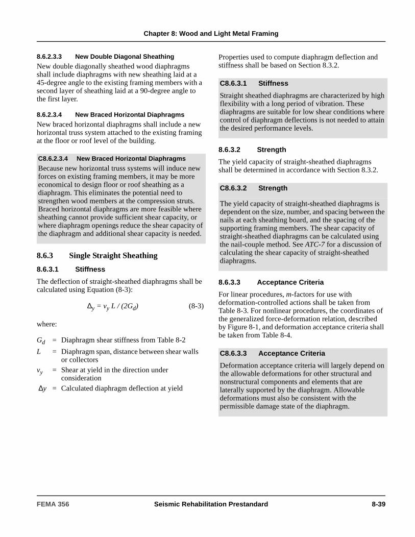
Chapter 8: Wood and Light Metal Framing
8.6.2.3.3 New Double Diagonal Sheathing
New double diagonally sheathed wood diaphragms shall include diaphragms with new sheathing laid at a 45-degree angle to the existing framing members with a second layer of sheathing laid at a 90-degree angle to the first layer.
8.6.2.3.4 New Braced Horizontal Diaphragms
New braced horizontal diaphragms shall include a new horizontal truss system attached to the existing framing at the floor or roof level of the building.
8.6.3 Single Straight Sheathing
8.6.3.1 Stiffness
The deflection of straight-sheathed diaphragms shall be calculated using Equation (8-3):
∆y = vy L / (2Gd) (8-3)
where:
Properties used to compute diaphragm deflection and stiffness shall be based on Section 8.3.2.
8.6.3.2 Strength
The yield capacity of straight-sheathed diaphragms shall be determined in accordance with Section 8.3.2.
8.6.3.3 Acceptance Criteria
For linear procedures, m-factors for use with deformation-controlled actions shall be taken from Table 8-3. For nonlinear procedures, the coordinates of the generalized force-deformation relation, described by Figure 8-1, and deformation acceptance criteria shall be taken from Table 8-4.
C8.6.2.3.4 New Braced Horizontal Diaphragms
Because new horizontal truss systems will induce new forces on existing framing members, it may be more economical to design floor or roof sheathing as a diaphragm. This eliminates the potential need to strengthen wood members at the compression struts. Braced horizontal diaphragms are more feasible where sheathing cannot provide sufficient shear capacity, or where diaphragm openings reduce the shear capacity of the diaphragm and additional shear capacity is needed.
Gd = Diaphragm shear stiffness from Table 8-2
L = Diaphragm span, distance between shear walls or collectors
vy = Shear at yield in the direction under consideration
∆y = Calculated diaphragm deflection at yield
C8.6.3.1 Stiffness
Straight sheathed diaphragms are characterized by high flexibility with a long period of vibration. These diaphragms are suitable for low shear conditions where control of diaphragm deflections is not needed to attain the desired performance levels.
C8.6.3.2 Strength
The yield capacity of straight-sheathed diaphragms is dependent on the size, number, and spacing between the nails at each sheathing board, and the spacing of the supporting framing members. The shear capacity of straight-sheathed diaphragms can be calculated using the nail-couple method. See ATC-7 for a discussion of calculating the shear capacity of straight-sheathed diaphragms.
C8.6.3.3 Acceptance Criteria
Deformation acceptance criteria will largely depend on the allowable deformations for other structural and nonstructural components and elements that are laterally supported by the diaphragm. Allowable deformations must also be consistent with the permissible damage state of the diaphragm.
FEMA 356 Seismic Rehabilitation Prestandard 8-39
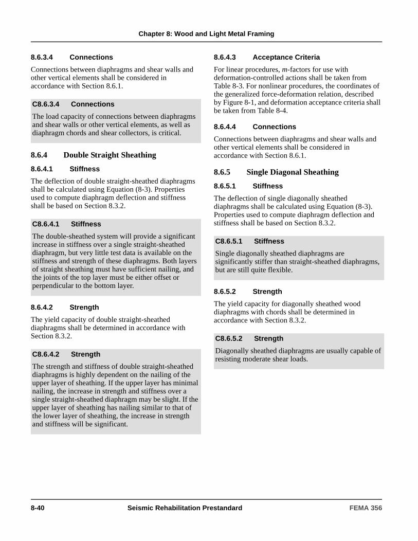
Chapter 8: Wood and Light Metal Framing
8.6.3.4 Connections
Connections between diaphragms and shear walls and other vertical elements shall be considered in accordance with Section 8.6.1.
8.6.4 Double Straight Sheathing
8.6.4.1 Stiffness
The deflection of double straight-sheathed diaphragms shall be calculated using Equation (8-3). Properties used to compute diaphragm deflection and stiffness shall be based on Section 8.3.2.
8.6.4.2 Strength
The yield capacity of double straight-sheathed diaphragms shall be determined in accordance with Section 8.3.2.
8.6.4.3 Acceptance Criteria
For linear procedures, m-factors for use with deformation-controlled actions shall be taken from Table 8-3. For nonlinear procedures, the coordinates of the generalized force-deformation relation, described by Figure 8-1, and deformation acceptance criteria shall be taken from Table 8-4.
8.6.4.4 Connections
Connections between diaphragms and shear walls and other vertical elements shall be considered in accordance with Section 8.6.1.
8.6.5 Single Diagonal Sheathing
8.6.5.1 Stiffness
The deflection of single diagonally sheathed diaphragms shall be calculated using Equation (8-3). Properties used to compute diaphragm deflection and stiffness shall be based on Section 8.3.2.
8.6.5.2 Strength
The yield capacity for diagonally sheathed wood diaphragms with chords shall be determined in accordance with Section 8.3.2.
C8.6.3.4 Connections
The load capacity of connections between diaphragms and shear walls or other vertical elements, as well as diaphragm chords and shear collectors, is critical.
C8.6.4.1 Stiffness
The double-sheathed system will provide a significant increase in stiffness over a single straight-sheathed diaphragm, but very little test data is available on the stiffness and strength of these diaphragms. Both layers of straight sheathing must have sufficient nailing, and the joints of the top layer must be either offset or perpendicular to the bottom layer.
C8.6.4.2 Strength
The strength and stiffness of double straight-sheathed diaphragms is highly dependent on the nailing of the upper layer of sheathing. If the upper layer has minimal nailing, the increase in strength and stiffness over a single straight-sheathed diaphragm may be slight. If the upper layer of sheathing has nailing similar to that of the lower layer of sheathing, the increase in strength and stiffness will be significant.
C8.6.5.1 Stiffness
Single diagonally sheathed diaphragms are significantly stiffer than straight-sheathed diaphragms, but are still quite flexible.
C8.6.5.2 Strength
Diagonally sheathed diaphragms are usually capable of resisting moderate shear loads.
8-40 Seismic Rehabilitation Prestandard FEMA 356
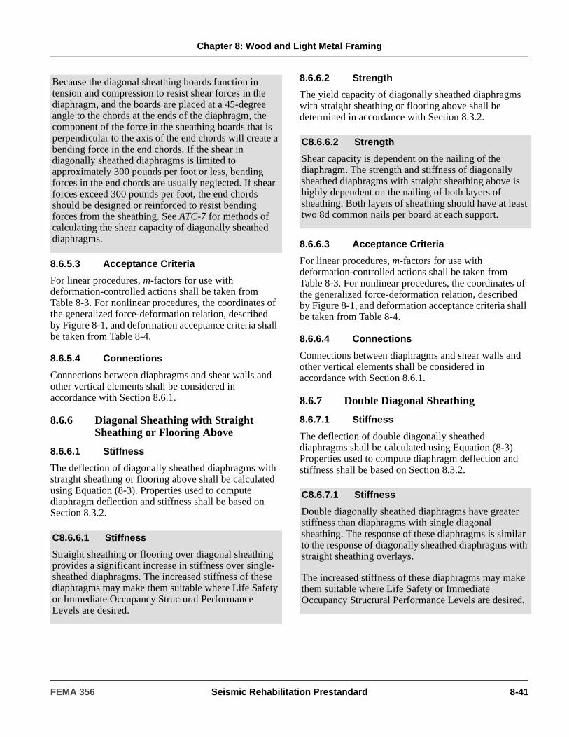
Chapter 8: Wood and Light Metal Framing
8.6.5.3 Acceptance Criteria
For linear procedures, m-factors for use with deformation-controlled actions shall be taken from Table 8-3. For nonlinear procedures, the coordinates of the generalized force-deformation relation, described by Figure 8-1, and deformation acceptance criteria shall be taken from Table 8-4.
8.6.5.4 Connections
Connections between diaphragms and shear walls and other vertical elements shall be considered in accordance with Section 8.6.1.
8.6.6 Diagonal Sheathing with Straight Sheathing or Flooring Above
8.6.6.1 Stiffness
The deflection of diagonally sheathed diaphragms with straight sheathing or flooring above shall be calculated using Equation (8-3). Properties used to compute diaphragm deflection and stiffness shall be based on Section 8.3.2.
8.6.6.2 Strength
The yield capacity of diagonally sheathed diaphragms with straight sheathing or flooring above shall be determined in accordance with Section 8.3.2.
8.6.6.3 Acceptance Criteria
For linear procedures, m-factors for use with deformation-controlled actions shall be taken from Table 8-3. For nonlinear procedures, the coordinates of the generalized force-deformation relation, described by Figure 8-1, and deformation acceptance criteria shall be taken from Table 8-4.
8.6.6.4 Connections
Connections between diaphragms and shear walls and other vertical elements shall be considered in accordance with Section 8.6.1.
8.6.7 Double Diagonal Sheathing
8.6.7.1 Stiffness
The deflection of double diagonally sheathed diaphragms shall be calculated using Equation (8-3). Properties used to compute diaphragm deflection and stiffness shall be based on Section 8.3.2.
Because the diagonal sheathing boards function in tension and compression to resist shear forces in the diaphragm, and the boards are placed at a 45-degree angle to the chords at the ends of the diaphragm, the component of the force in the sheathing boards that is perpendicular to the axis of the end chords will create a bending force in the end chords. If the shear in diagonally sheathed diaphragms is limited to approximately 300 pounds per foot or less, bending forces in the end chords are usually neglected. If shear forces exceed 300 pounds per foot, the end chords should be designed or reinforced to resist bending forces from the sheathing. See ATC-7 for methods of calculating the shear capacity of diagonally sheathed diaphragms.
C8.6.6.1 Stiffness
Straight sheathing or flooring over diagonal sheathing provides a significant increase in stiffness over single-sheathed diaphragms. The increased stiffness of these diaphragms may make them suitable where Life Safety or Immediate Occupancy Structural Performance Levels are desired.
C8.6.6.2 Strength
Shear capacity is dependent on the nailing of the diaphragm. The strength and stiffness of diagonally sheathed diaphragms with straight sheathing above is highly dependent on the nailing of both layers of sheathing. Both layers of sheathing should have at least two 8d common nails per board at each support.
C8.6.7.1 Stiffness
Double diagonally sheathed diaphragms have greater stiffness than diaphragms with single diagonal sheathing. The response of these diaphragms is similar to the response of diagonally sheathed diaphragms with straight sheathing overlays.
The increased stiffness of these diaphragms may make them suitable where Life Safety or Immediate Occupancy Structural Performance Levels are desired.
FEMA 356 Seismic Rehabilitation Prestandard 8-41
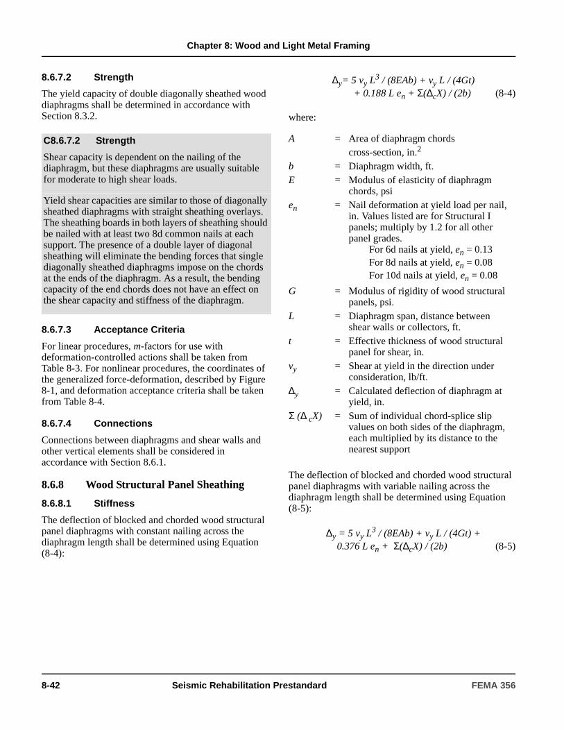
Chapter 8: Wood and Light Metal Framing
8.6.7.2 Strength
The yield capacity of double diagonally sheathed wood diaphragms shall be determined in accordance with Section 8.3.2.
8.6.7.3 Acceptance Criteria
For linear procedures, m-factors for use with deformation-controlled actions shall be taken from Table 8-3. For nonlinear procedures, the coordinates of the generalized force-deformation, described by Figure 8-1, and deformation acceptance criteria shall be taken from Table 8-4.
8.6.7.4 Connections
Connections between diaphragms and shear walls and other vertical elements shall be considered in accordance with Section 8.6.1.
8.6.8 Wood Structural Panel Sheathing
8.6.8.1 Stiffness
The deflection of blocked and chorded wood structural panel diaphragms with constant nailing across the diaphragm length shall be determined using Equation (8-4):
∆y= 5 vy L3 / (8EAb) + vy L / (4Gt)
+ 0.188 L en + Σ(∆cX) / (2b) (8-4)
where:
The deflection of blocked and chorded wood structural panel diaphragms with variable nailing across the diaphragm length shall be determined using Equation (8-5):
∆y = 5 vy L3 / (8EAb) + vy L / (4Gt) +
0.376 L en + Σ(∆cX) / (2b) (8-5)
C8.6.7.2 Strength
Shear capacity is dependent on the nailing of the diaphragm, but these diaphragms are usually suitable for moderate to high shear loads.
Yield shear capacities are similar to those of diagonally sheathed diaphragms with straight sheathing overlays. The sheathing boards in both layers of sheathing should be nailed with at least two 8d common nails at each support. The presence of a double layer of diagonal sheathing will eliminate the bending forces that single diagonally sheathed diaphragms impose on the chords at the ends of the diaphragm. As a result, the bending capacity of the end chords does not have an effect on the shear capacity and stiffness of the diaphragm.
A = Area of diaphragm chordscross-section, in.2
b = Diaphragm width, ft.E = Modulus of elasticity of diaphragm
chords, psien = Nail deformation at yield load per nail,
in. Values listed are for Structural I panels; multiply by 1.2 for all other panel grades.
For 6d nails at yield, en = 0.13For 8d nails at yield, en = 0.08For 10d nails at yield, en = 0.08
G = Modulus of rigidity of wood structural panels, psi.
L = Diaphragm span, distance between shear walls or collectors, ft.
t = Effective thickness of wood structural panel for shear, in.
vy = Shear at yield in the direction under consideration, lb/ft.
∆y = Calculated deflection of diaphragm at yield, in.
Σ (∆ cX) = Sum of individual chord-splice slip values on both sides of the diaphragm, each multiplied by its distance to the nearest support
8-42 Seismic Rehabilitation Prestandard FEMA 356
Chapter 8: Wood and Light Metal Framing
The deflection of unblocked diaphragms shall be calculated using Equation (8-3). Properties used to compute diaphragm deflection and stiffness shall be based on Section 8.3.2.
8.6.8.2 Strength
The strength of wood structural panel diaphragms shall be determined in accordance with Section 8.4.2.2.
Conversion for tabulated allowable stress values in accordance with Section 8.3.2.5 shall not be permitted for wood structural panel diaphragms, but approved allowable stress values for fasteners shall be permitted to be converted in accordance with Section 8.3.2.5 where the strength of a shear wall is computed using principles of mechanics.
The yield shear capacity of unchorded diaphragms shall be calculated by multiplying the values given for chorded diaphragms by 0.70.
8.6.8.3 Acceptance Criteria
For linear procedures, m-factors for use with deformation-controlled actions shall be taken from Table 8-3. For nonlinear procedures, the coordinates of the generalized force-deformation relation, described by Figure 8-1, and deformation acceptance criteria shall be taken from Table 8-4.
8.6.8.4 Connections
Connections between diaphragms and shear walls and other vertical elements shall be considered in accordance with Section 8.6.1.
8.6.9 Wood Structural Panel Overlays on Straight or Diagonal Sheathing
8.6.9.1 Stiffness
Placement of the new wood structural panel overlay shall be consistent with Section 8.6.2.2.
The deflection of wood structural panel overlays on straight or diagonally sheathed diaphragms shall be calculated using Equation (8-3). Properties used to compute diaphragm deflection and stiffness shall be based on Section 8.3.2.
C8.6.8.1 Stiffness
The response of wood structural panel diaphragms is dependent on the thickness of the wood structural panels, the length-to-width (L/b) ratio, nailing pattern, and presence of chords in the diaphragm, as well as other factors. Values for modulus rigidity, G, and effective thickness, t, for various sheathing materials are contained in APA (1995 and 1997).
In most cases the area of the diaphragm chord equals the area of the continuous wood (or steel) member to which the sheathing is attached. For buildings with wood diaphragms and concrete or masonry walls, however, the area of the diaphragm chord is more difficult to identify and engineering judgment is required. The tension area of the diaphragm chord on both edges of the diaphragm should be used for deflection calculations. Generally, this is conservative as it results in a larger calculated deflection. Use of the tension area of the diaphragm chord may not yield conservative results, however, when calculating the period of the building using Equation (3-8).
C8.6.8.2 Strength
Shear capacities of wood structural panel diaphragms are primarily dependent on the nailing at the plywood panel edges, and the thickness and grade of the plywood in the diaphragm.
LRFD-based design values for various configurations are listed in AF&PA LRFD and BSSC (2000). A method for calculating the capacity of wood structural panel diaphragms based on accepted nail values and panel shear strength is provided in Tissell and Elliott (1997). For this method, use LRFD-based fastener strengths. Due to the differences in load duration/time effect factors between the allowable stress and LRFD formats, direct conversion of diaphragm tables using the method outlined in Section 8.3.2.5 is not permitted. However, the tabulated LRFD design values, with φ= 1, are intended to be 2.0 times the associated allowable stress design values.
C8.6.9.1 Stiffness
The stiffness of existing straight-sheathed diaphragms can be increased significantly by placing a new plywood overlay over the existing diaphragm. The stiffness of existing diagonally sheathed diaphragms and plywood diaphragms will be increased, but not in proportion to the stiffness increase for straight-sheathed diaphragms.
FEMA 356 Seismic Rehabilitation Prestandard 8-43

Chapter 8: Wood and Light Metal Framing
8.6.9.2 Strength
Strength of wood structural panel overlays shall be determined in accordance with Section 8.4.2.2. It shall be permitted to take the yield capacity as the value for the corresponding wood structural panel diaphragm without the existing sheathing below, computed in accordance with Section 8.6.8.2.
8.6.9.3 Acceptance Criteria
For linear procedures, m-factors for use with deformation-controlled actions shall be taken from Table 8-3. For nonlinear procedures, the coordinates of the generalized force-deformation relation, described by Figure 8-1, and deformation acceptance criteria shall be taken from Table 8-4.
8.6.9.4 Connections
Connections between diaphragms and shear walls and other vertical elements shall be considered in accordance with Section 8.6.1.
8.6.10 Wood Structural Panel Overlays on Existing Wood Structural Panel Sheathing
8.6.10.1 Stiffness
Diaphragm deflection shall be calculated in accordance with Equation (8-3) or using accepted principles of mechanics. Nails in the upper layer of plywood shall have sufficient embedment in the framing to meet the requirements of ASCE 16.
8.6.10.2 Strength
Yield capacity shall be calculated based on the combined two layers of plywood. The yield shear capacity of the overlay shall be limited to 75% of the values calculated in accordance with Section 8.6.8.2.
8.6.10.3 Acceptance Criteria
For linear procedures, m-factors for use with deformation-controlled actions shall be taken from Table 8-3. For nonlinear procedures, the coordinates of the generalized force-deformation relation, described by Figure 8-1, and deformation acceptance criteria shall be taken from Table 8-4.
8.6.10.4 Connections
Connections between diaphragms and shear walls and other vertical elements shall be considered in accordance with Section 8.6.1.
8.6.11 Braced Horizontal Diaphragms
Braced horizontal diaphragms shall be considered in accordance with Section 8.8.1.
Connections between members of the horizontal bracing system and shear walls or other vertical elements shall be considered in accordance with Section 8.6.1.
8.7 Wood Foundations
8.7.1 Types of Wood Foundations
Types of wood foundations include wood piling, wood footings, and pole structures. Wood piling shall include friction or end-bearing piles that resist only vertical loads.
Depending on the nailing of the new overlay, the response of the diaphragm may be similar to that of a blocked or an unblocked diaphragm.
The increased stiffness of these diaphragms may make them suitable where Life Safety or Immediate Occupancy Structural Performance Levels are desired.
C8.6.10.1 Stiffness
According to Tissell and Elliott (1997), Equation (8-4) is not applicable to two-layer diaphragms, presumably due to the difficulty in estimating the combined nail slip. Diaphragm deflection may be estimated using principles of mechanics that include consideration of nail slip, blocking, and the embedment of nails into the framing.
C8.7.1 Types of Wood Foundations
1. Wood Piling. Wood piles are generally used with a concrete pile cap and are usually keyed into the base of the concrete cap. The piles are usually treated with preservatives.
8-44 Seismic Rehabilitation Prestandard FEMA 356
Chapter 8: Wood and Light Metal Framing
8.7.2 Analysis, Strength, and Acceptance Criteria of Wood Foundations
The expected strength of wood piles shall be computed in accordance with Section 8.4.2.2. Deflection of piles under seismic loads shall be calculated based on an assumed point of fixity. Unless rigidly connected to the pile cap, wood piles shall be taken as pinned at the top.
Flexure and axial loads in wood piles shall be considered deformation-controlled. m-factors shall be taken from Table 8-3.
Wood footings shall be thoroughly investigated for the presence of deterioration. Acceptability of soils below wood footings shall be determined in accordance with Chapter 4.
Component and connection strength of pole structures shall be based on Section 8.3. Pole structures shall be modeled as cantilever elements and analyzed in accordance with Chapter 3.
Flexure and axial loads in pole structures shall be considered deformation controlled. m-factors shall be taken from Table 8-3. Where concentrically braced diagonals are added to enhance the capacity of the pole structure, reduced m-factors taken from Table 8-3 shall be used.
8.7.3 Rehabilitation Measures
Wood foundations not meeting the acceptance criteria for the selected Rehabilitation Objective shall be rehabilitated by approved methods. Wood foundations exhibiting signs of deterioration shall be rehabilitated or replaced.
Piles are either friction- or end-bearing piles resisting only vertical loads. Piles are generally not able to resist uplift loads because of the manner in which they are attached to the pile cap. The piles may be subjected to lateral loads from seismic loading, which are resisted by bending of the piles. The analysis of pile bending is generally based on a pinned connection at the top of the pile, and fixity of the pile at some depth established by the geotechnical engineer. However, it should be evaluated with consideration for the approximate nature of the original assumption of the depth to point of fixity. Where battered piles are present, the lateral loads can be resisted by the horizontal component of the axial load.
2. Wood Footings. Wood grillage footings, sleepers, skids, and pressure-treated all-wood foundations can be encountered in existing structures. These foundations are highly susceptible to deterioration. The seismic resistance of wood footings is generally very low; they are essentially dependent on friction between the wood and soil for their performance.
3. Pole Structures. Pole structures resist lateral loads by acting as cantilevers fixed in the ground, with the lateral load considered to be applied perpendicular to the pole axis. It is possible to design pole structures to have moment-resisting capacity at floor and roof levels by the use of knee braces or trusses. Pole structures are frequently found on sloping sites. The varying unbraced lengths of the poles generally affect the stiffness and performance of the structure, and can result in unbalanced loads to the various poles along with significant torsional distortion, which must be investigated and evaluated. Additional horizontal and diagonal braces can be used to reduce the flexibility of tall poles or reduce the torsional eccentricity of the structure.
C8.7.2 Analysis, Strength, and Acceptance Criteria of Wood Foundations
The strength of the components, elements, and connections of a pole structure are the same as for a conventional structure.
C8.7.3 Rehabilitation Measures
Wood footings showing signs of deterioration may be replaced with reinforced concrete footings. Wood pole structures can be rehabilitated with the installation of diagonal braces or other supplemental lateral-force-resisting elements. Wood piles may be rehabilitated by the installation of additional piles.
FEMA 356 Seismic Rehabilitation Prestandard 8-45

Chapter 8: Wood and Light Metal Framing
8.8 Other Wood Elements and Components
8.8.1 General
Wood elements and components, other than shear walls, diaphragms, and foundations, shall be considered in accordance with this section. Where an assembly includes wood components and steel rods, the rods shall be considered in accordance with applicable provisions of Chapter 5.
8.8.1.1 Stiffness
The stiffness and deflection of wood elements shall be determined based on a mathematical model of the assembly considering the configuration, stiffness, and interconnection of the individual components.
8.8.1.2 Strength
The capacities of individual components, including connections, shall be determined in accordance with Section 8.4.2.
8.8.1.3 Acceptance Criteria
Design actions shall be compared with design capacities in accordance with Section 3.4.2.2. Connections shall be considered in accordance with Section 8.4.3. Axial tension, axial tension with bending shall be considered deformation-controlled. Axial compression, and connections between steel rods and wood components shall be considered force-controlled. m-factors for deformation-controlled actions shall be taken from Table 8-3. For nonlinear procedures, coordinates of the generalized force-deformation relation described by Figure 8-1, and deformation acceptance criteria shall be taken from Table 8-4.
8.8.2 Components Supporting Discontinuous Shear Walls
Axial compression on wood posts and flexure and shear on wood beams that support discontinuous shear walls shall be considered force-controlled actions. Lower-bound strengths shall be determined in accordance with Section 8.4.2.3.
C8.8.1 General
Other wood elements include knee-braced frames, rod-braced frames, and braced horizontal diaphragms, among other systems.
Knee-braced frames produce moment-resisting joints by the addition of diagonal members between columns and beams. The resulting “semi-rigid” frame resists lat-eral loads. The moment-resisting capacity of knee-braced frames varies widely. The controlling part of the assembly is usually the connection; however, bending of members can be the controlling feature of some frames. Once the capacity of the connection is deter-mined, members can be checked and the capacity of the frame can be determined by statics. Particular attention should be given to the beam/column connection. Addi-tional tensile forces may be developed in this connec-tion due to knee-brace action under vertical loads.
Similarly to knee-braced frames, the connections of rods to timber framing will usually govern the capacity of the rod-braced frame. Typically, the rods act only in tension. Once the capacity of the connection is determined, the capacity of the frame can be determined by statics.
Braced horizontal diaphragms are described in Section 8.6.2.1.7.
C8.8.1.2 Strength
The strength of wood elements is dependent on the strength of the individual components that comprise the assembly. In many cases the capacity of the connections between components will be the limiting factor in the strength of the assembly.
C8.8.1.3 Acceptance Criteria
Deformation acceptance criteria will largely depend on the allowable deformations for other structural and nonstructural components and elements that are supported by the element. Allowable deformations must also be consistent with the desired performance level. Actions on connection types that do not appear in Table 8-3 (e.g., truss plates) are force-controlled.
8-46 Seismic Rehabilitation Prestandard FEMA 356

9. Seismic Isolation and Energy Dissipation
9.1 Scope This chapter sets forth requirements for the Systematic Rehabilitation of buildings using seismic isolation and energy dissipation systems. Section 9.2 provides analysis and design criteria for seismic isolation systems. Section 9.3 provides analysis and design criteria for passive energy dissipation systems.
Components and elements in buildings with seismic isolation and energy dissipation systems shall also comply with the requirements of Chapters 1 through 8 and 11 of this standard, unless modified by the requirements of this chapter.
C9.1 Scope The basic form and formulation of requirements for seismic isolation and energy dissipation systems have been established and coordinated with the Rehabilitation Objectives, target Building Performance Levels, and seismic ground shaking hazard criteria of Chapter 1 and the linear and nonlinear procedures of Chapter 3.
Criteria for modeling the stiffness, strength, and deformation capacities of conventional structural components of buildings with seismic isolation or energy dissipation systems are given in Chapters 5 through 8 and Chapter 10.
Limited guidance for other special seismic systems, including active control systems, hybrid active and passive systems, and tuned mass and liquid dampers, is provided in this chapter.
Special seismic protective systems should be evaluated as possible rehabilitation strategies based on the Rehabilitation Objectives established for the building.
Seismic isolation and energy dissipation systems are viable design strategies that have already been used for seismic rehabilitation of a number of buildings. Other special seismic protective systems—including active control, hybrid combinations of active and passive energy devices, and tuned mass and liquid dampers—may also provide practical solutions in the near future. These systems are similar in that they enhance performance during an earthquake by modifying the building’s response characteristics.
Seismic isolation and energy dissipation systems will not be appropriate design strategies for most buildings, particularly buildings that have only Limited Rehabilitation Objectives. In general, these systems will be most applicable to the rehabilitation of buildings whose owners desire superior earthquake performance and can afford the special costs associated with the design, fabrication, and installation of seismic isolators and/or energy dissipation devices. These costs are typically offset by the reduced need for stiffening and strengthening measures that would otherwise be required to meet Rehabilitation Objectives.
Seismic isolation and energy dissipation systems are relatively new and sophisticated concepts that require more extensive design and detailed analysis than do most conventional rehabilitation schemes. Similarly, design (peer) review is required for all rehabilitation schemes that use either seismic isolation or energy dissipation systems.
Seismic isolation and energy dissipation systems include a wide variety of concepts and devices. In most cases, these systems and devices will be implemented with some additional conventional strengthening of the structure; in all cases they will require evaluation of existing building elements. As such, this chapter supplements the requirements of other chapters of this document with additional criteria and methods of analysis that are appropriate for buildings rehabilitated with seismic isolators and/or energy dissipation devices.
FEMA 356 Seismic Rehabilitation Prestandard 9-1

Chapter 9: Seismic Isolation and
Energy Dissipation
Seismic isolation is increasingly being considered for historic buildings that are free-standing and have a basement or bottom space of no particular historic significance. In selecting such a solution, special consideration should be given to the possibility that historic or archaeological resources may be present at the site. If historic or archaeological resources are present at the site, the guidance of the State Historic Preservation Officer should be obtained in a timely manner. Isolation is also often considered for essential facilities, to protect valuable contents, and on buildings with a complete but insufficiently strong lateral-force-resisting system.
Conceptually, isolation reduces response of the superstructure by “decoupling” the building from the ground. Typical isolation systems reduce forces transmitted to the superstructure by lengthening the period of the building and adding some amount of damping. Added damping is an inherent property of most isolators, but may also be provided by supplemental energy dissipation devices installed across the isolation interface. Under favorable conditions, the isolation system reduces drift in the superstructure by a factor of at least two—and sometimes by as much as factor of five—from that which would occur if the building were not isolated. Accelerations are also reduced in the structure, although the amount of reduction depends on the force-deflection characteristics of the isolators and may not be as significant as the reduction of drift. Reduction of drift in the superstructure protects structural components and elements, as well as nonstructural components sensitive to drift-induced damage. Reduction of acceleration protects nonstructural components that are sensitive to acceleration-induced damage.
Passive energy dissipation devices add damping (and sometimes stiffness) to the building. A wide variety of passive energy dissipation devices are available, including fluid viscous dampers, viscoelastic materials, and hysteretic devices. Ideally, energy dissipation devices dampen earthquake excitation of the structure that would otherwise cause higher levels of response and damage to components of the building. Under favorable conditions, energy dissipation devices reduce drift of the structure by a factor of about two to three (if no stiffness is added) and by larger factors if the devices also add stiffness to the structure. Energy dissipation devices will also reduce force in the structure—provided the structure is responding elastically—but would not be expected to reduce force in structures that are responding beyond yield.
Active control systems sense and resist building motion, either by applying external force or by modifying structural properties of active elements (e.g., so-called “smart” braces). Tuned mass or liquid dampers modify properties and add damping to key building modes of vibration.
Special seismic systems, such as isolation or energy dissipation systems, should be considered early in the design process and be based on the Rehabilitation Objectives established for the building (Chapter 2). Whether a special seismic system is found to be the “correct” design strategy for building rehabilitation will depend primarily on the performance required at the specified level of earthquake demand. In general, special seismic systems will be found to be more attractive as a rehabilitation strategy for buildings that have more stringent Rehabilitation Objectives (i.e., higher levels of performance and more severe levels of earthquake demand). Table C9-1 provides some simple guidance on the performance levels for which isolation and energy dissipation systems should be considered as possible design strategies for building rehabilitation.
9-2 Seismic Rehabilitation Prestandard FEMA 356

Chapter 9: Seismic Isolation and
Energy Dissipation
9.2 Seismic Isolation Systems
9.2.1 General Requirements
Seismic isolation systems using seismic isolators, classified as either elastomeric or sliding, as defined in Section 9.2.2, shall comply with the requirements of Section 9.2. Properties of seismic isolation systems shall be based on Section 9.2.2. Seismic isolation systems shall be designed and analyzed in accordance with Section 9.2.3. Linear and nonlinear analyses shall be performed, as required by Section 9.2.3, in accordance with Sections 9.2.4 and 9.2.5, respectively. Nonstructural components shall be rehabilitated in accordance with Section 9.2.6. Additional requirements for seismic isolation systems as defined in Section 9.2.7 shall be met. Seismic isolation systems shall be reviewed and tested in accordance with Sections 9.2.8 and 9.2.9, respectively.
The seismic isolation system shall include wind-restraint and tie-down systems, if such systems are required by this standard. The isolation system also shall include supplemental energy dissipation devices, if such devices are used to transmit force between the structure above the isolation system and the structure below the isolation system.
For seismically isolated structures, the coefficients C0, C1, C2, C3, and J defined in Chapter 3, shall be taken as 1.0
Table C9-1 suggests that isolation systems should be considered for achieving the Immediate Occupancy Structural Performance Level and the Operational Nonstructural Performance Level. Conversely, isolation will likely not be an appropriate design strategy for achieving the Collapse Prevention Structural Performance Level. In general, isolation systems provide significant protection to the building structure, nonstructural components, and contents, but at a cost that precludes practical application when the budget and Rehabilitation Objectives are modest.
Energy dissipation systems should be considered in a somewhat broader context than isolation systems. For the taller buildings (where isolation systems may not be feasible), energy dissipation systems should be considered as a design strategy when performance goals include the Damage Control Performance Range. Conversely, certain energy dissipation devices are quite economical and might be practical for performance goals that address only Limited Safety. In general, however, energy dissipation systems are more likely to be an appropriate design strategy when the desired Structural Performance Level is Life Safety, or perhaps Immediate Occupancy. Other objectives may also influence the decision to use energy dissipation devices, since these devices can also be useful for control of building response due to small earthquakes, wind, or mechanical loads.
Table C9-1 Applicability of Isolation and Energy Dissipation Systems
PerformanceLevel
PerformanceRange Isolation
EnergyDissipation
Operational Damage Control
Very Likely
Limited
ImmediateOccupancy
Likely Likely
LifeSafety
Limited Safety
Limited Likely
CollapsePrevention
NotPractical
Limited
C9.2.1 General Requirements
Analysis methods and design criteria for seismic isolation systems are based on criteria for the Rehabilitation Objectives of Chapter 1.
The methods described in this section augment the analysis requirements of Chapter 3. The analysis methods and other criteria of this section are based largely on FEMA 302, 1997 NEHRP Provisions.
FEMA 356 Seismic Rehabilitation Prestandard 9-3

Chapter 9: Seismic Isolation and
Energy Dissipation
9.2.2 Mechanical Properties and Modeling of Seismic Isolation Systems
9.2.2.1 General
Seismic isolators shall be classified as either elastomeric or sliding. Elastomeric isolators shall include any one of the following: high-damping rubber bearings (HDR), low-damping rubber bearings (RB) or low-damping rubber bearings with a lead core (LRB). Sliding isolators shall include flat assemblies or have a curved surface, such as the friction-pendulum system (FPS). Rolling systems shall be characterized as a subset of sliding systems. Rolling isolators shall be flat assemblies or have a curved or conical surface, such as the ball and cone system (BNC). Isolators that cannot be classified as either elastomeric or sliding are not addressed in this standard.
9.2.2.2 Mechanical Properties of Seismic Isolators
9.2.2.2.1 Elastomeric Isolators
Force-deformation response properties shall be established for elastomeric isolators taking into consideration axial-shear interaction, bilateral deformation, load history including the effects of scragging of virgin elastomeric isolators, temperature, and other environmental loads and aging effects over the design life of the isolator.
For mathematical modeling of isolators, mechanical characteristics based on analysis or available material test properties shall be permitted. For design, mechanical characteristics shall be based on tests of isolator prototypes in accordance with Section 9.2.9.
Seismic isolation has typically been used as a rehabilitation strategy that enhances the performance of the building above that afforded by conventional stiffening and strengthening schemes. Seismic isolation rehabilitation projects have targeted performance at least equal to, and commonly exceeding, the Basic Safety Objective of this standard, effectively achieving a target Building Performance Level of Immediate Occupancy or better.
A number of buildings rehabilitated with seismic isolators have been historic. For these projects, seismic isolation reduced the extent and intrusion of seismic modifications on the historical fabric of the building that would otherwise be required to meet desired performance levels.
C9.2.2.1 General
A seismic isolation system is the collection of all individual seismic isolators (and separate wind restraint and tie-down devices, if such devices are used to meet the requirements of this standard). Seismic isolation systems may be composed entirely of one type of seismic isolator, a combination of different types of seismic isolators, or a combination of seismic isolators acting in parallel with energy dissipation devices (i.e., a hybrid system).
Elastomeric isolators are typically made of layers of rubber separated by steel shims.
C9.2.2.2.1 Elastomeric Isolators
Elastomeric bearings represent a common means for introducing flexibility into an isolated structure. They consist of thin layers of natural rubber that are vulcanized and bonded to steel plates. Natural rubber exhibits a complex mechanical behavior, which can be described simply as a combination of viscoelastic and hysteretic behavior. Low-damping natural rubber bearings exhibit essentially linearly elastic and linearly viscous behavior at large shear strains. The effective damping is typically less than or equal to 0.07 for shear strains in the range of 0 to 2.0.
Lead-rubber bearings are generally constructed of low-damping natural rubber with a preformed central hole into which a lead core is press-fitted. Under lateral deformation, the lead core deforms in almost pure shear, yields at low levels of stress (approximately 8 to 10 MPa in shear at normal temperature), and produces hysteretic behavior that is stable over many cycles. Unlike mild steel, lead recrystallizes at normal temperature (about 20°C), so that repeated yielding does not cause fatigue failure. Lead-rubber bearings generally exhibit characteristic strength that ensures rigidity under service loads. Figure C9-1 shows an idealized force-displacement relation of a lead-rubber bearing. The characteristic strength, Q, is related to the lead plug area, , and the shear yield stress of lead,
:
(C9-1)
Ap
σYL
Q ApσYL=
9-4 Seismic Rehabilitation Prestandard FEMA 356

Chapter 9: Seismic Isolation and
Energy Dissipation
Figure C9-1 Idealized Hysteretic Force-Displacement Relation of a Lead-Rubber Bearing
The post-yield stiffness, , is typically higher than the
shear stiffness of the bearing without the lead core:
(C9-2)
where is the bonded rubber area, is the total
rubber thickness, G is the shear modulus of rubber (typically computed at shear strain of 0.5), and is a
factor larger than unity. Typically, is 1.15, and the
elastic stiffness ranges between 6.5 to 10 times the post-yield stiffness.
kp
kp
ArGfL
Σt---------------=
Ar Σt
fLfL
The behavior of lead-rubber bearings may be represented by a bilinear hysteretic model. Computer programs 3D-BASIS (Nagarajaiah et al.; Reinhorn et al. (1994); Tsopelas et al. (1994b), and ETABS, Version 6 have the capability of modeling hysteretic behavior for isolators. These models typically require definition of three parameters, namely, the post-yield stiffness ,
the yield force Fy, and the yield displacement Dy . For lead-rubber bearings in which the elastic stiffness is approximately equal to 6.5 , the yield displacement
can be estimated as:
(C9-3)
The yield force is then given by:
(C9-4)
High-damping rubber bearings are made of specially compounded rubber that exhibits effective damping between 0.10 and 0.20 of critical. The increase in effective damping of high-damping rubber is achieved by the addition of chemical compounds that may also affect other mechanical properties of rubber. Figure C9-2 shows representative force-displacement loops of a high-damping rubber bearing under scragged conditions.
Scragging is the process of subjecting an elastomeric bearing to one or more cycles of large amplitude displacement. The scragging process modifies the molecular structure of the elastomer and results in more stable hysteresis at strain levels lower than that to which the elastomer was scragged. Although it is usually assumed that the scragged properties of an elastomer remain unchanged with time, recent studies by Cho and Retamal (1993) and Murota et al. (1994) suggest that partial recovery of unscragged properties is likely. The extent of this recovery is dependent on the elastomer compound.
kp
kp
DyQ
5.5kp-------------=
Fy Q kpDy+=
FEMA 356 Seismic Rehabilitation Prestandard 9-5
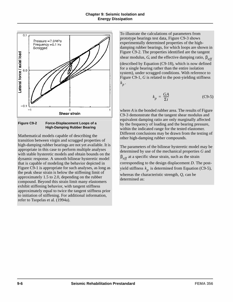
Chapter 9: Seismic Isolation and
Energy Dissipation
Figure C9-2 Force-Displacement Loops of a High-Damping Rubber Bearing
Mathematical models capable of describing the transition between virgin and scragged properties of high-damping rubber bearings are not yet available. It is appropriate in this case to perform multiple analyses with stable hysteretic models and obtain bounds on the dynamic response. A smooth bilinear hysteretic model that is capable of modeling the behavior depicted in Figure C9-1 is appropriate for such analyses, as long as the peak shear strain is below the stiffening limit of approximately 1.5 to 2.0, depending on the rubber compound. Beyond this strain limit many elastomers exhibit stiffening behavior, with tangent stiffness approximately equal to twice the tangent stiffness prior to initiation of stiffening. For additional information, refer to Tsopelas et al. (1994a).
To illustrate the calculations of parameters from prototype bearings test data, Figure C9-3 shows experimentally determined properties of the high-damping rubber bearings, for which loops are shown in Figure C9-2. The properties identified are the tangent shear modulus, G, and the effective damping ratio,
(described by Equation (C9-18), which is now defined for a single bearing rather than the entire isolation system), under scragged conditions. With reference to Figure C9-1, G is related to the post-yielding stiffness
.
(C9-5)
where A is the bonded rubber area. The results of Figure C9-3 demonstrate that the tangent shear modulus and equivalent damping ratio are only marginally affected by the frequency of loading and the bearing pressure, within the indicated range for the tested elastomer. Different conclusions may be drawn from the testing of other high-damping rubber compounds.
The parameters of the bilinear hysteretic model may be determined by use of the mechanical properties G and
at a specific shear strain, such as the strain
corresponding to the design displacement D. The post-yield stiffness is determined from Equation (C9-5),
whereas the characteristic strength, Q, can be determined as:
βeff
kp
kpGAΣt--------=
βeff
kp
9-6 Seismic Rehabilitation Prestandard FEMA 356

Chapter 9: Seismic Isolation and
Energy Dissipation
Figure C9-3 Tangent Shear Modulus and Effective Damping Ratio of High-Damping Rubber Bearing
(C9-6)
where Dy is the yield displacement. The yield displacement is generally not known a priori. However, experimental data suggest that Dy is approximately
equal to 0.05 to 0.1 times the total rubber thickness, . With the yield displacement approximately determined, the model can be completely defined by determining the yield force (Equation (C9-4)). It should be noted that the characteristic strength may be alternatively determined from the effective stiffness, (Equation
(C9-17)), of the bearing, as follows:
(C9-7)
QπβeffkpD
2
2 πβeff–( )D 2Dy–-----------------------------------------------=
Σt
keff
QπβeffkeffD
2
2 D Dy–( )----------------------------=
The effective stiffness is a more readily determined property than the post-yielding stiffness. The effective stiffness is commonly used to obtain the effective shear modulus, , defined as:
(C9-8)
The behavior of the bearing for which the force-displacement loops are shown in Figure C9-2 is now analytically constructed using the mechanical properties at a shear strain of 1.0 and a bearing pressure of 7.0 MPa. These properties are Geff = 0.50 MPa and
= 0.16. With the bonded area and total thickness of
rubber known, and assuming , a bilinear
hysteretic model was defined and implemented in the program 3D-BASIS. The simulated loops are shown in Figure C9-4, where it may be observed that the calculated hysteresis loop at shear strain of 1.0 agrees well with the corresponding experimental hysteresis loop. However, at lower peak shear strain the analytical loops have a constant characteristic strength, whereas the experimental loops have a characteristic strength dependent on the shear strain amplitude. Nevertheless, the analytical model will likely produce acceptable results when the design parameters are based on the mechanical properties at a strain corresponding to the design displacement.
Geff
Geff
keffΣt
A--------------=
βeff
Dy 0.1Σt=
FEMA 356 Seismic Rehabilitation Prestandard 9-7

Chapter 9: Seismic Isolation and
Energy Dissipation
9.2.2.2.2 Sliding Isolators
Force-deformation response properties shall be established for sliding isolators, taking into consideration contact pressure, rate of loading or velocity, bilateral deformation, temperature, contamination, and other environmental loads and aging effects over the design life of the isolator.
Mechanical characteristics for use in mathematical models shall be based on analysis and available material test properties. Verification of isolator properties used
Figure C9-4 Analytical Force-Displacement Loops of High-Damping Rubber Bearing
Elastomeric bearings have finite vertical stiffness that affects the vertical response of the isolated structure. The vertical stiffness of an elastomeric bearing may be obtained from
(C9-9)
where is the compression modulus. Although a
number of approximate empirical relations have been proposed for the calculation of the compression modulus, the correct expression for circular bearings is
(C9-10)
(Kelly, 1993) where K is the bulk modulus (typically assumed to have a value of 2000 MPa) and S is the shape factor, which is defined as the ratio of the loaded area to the bonded perimeter of a single rubber layer. For a circular bearing of bonded diameter φ and rubber layer thickness t, the shape factor is given by
kv
EcA
Σt----------=
Ec
Ec1
6GeffS2
------------------- 43K-------+
1–
=
(C9-11)
Seismic elastomeric bearings are generally designed with a large shape factor, typically 12 to 20. Considering an elastomeric bearing design with S = 15,
= 1 MPa, and K = 2000 MPa, the ratio of vertical
stiffness (Equation (C9-9)) to effective horizontal stiffness (Equation (C9-8)) is approximately equal to 700. Thus, the vertical period of vibration of a structure on elastomeric isolation bearings will be about 26 times
(i.e., ) less than the horizontal period, on the order of 0.1 second. This value of vertical period provides potential for amplification of the vertical ground acceleration by the isolation system. The primary effect of this amplification is to change the vertical load on the bearings, which may need to be considered for certain design applications.
Another consideration in the design of seismically isolated structures with elastomeric bearings is reduction in height of a bearing with increasing lateral deformation (Kelly, 1993). While this reduction of height is typically small, it may be important when elastomeric bearings are combined with other isolation elements that are vertically rigid (such as sliding bearings). In addition, incompatibilities in vertical displacements may lead to a redistribution of loads.
Sφ4t-----=
Geff
700
9-8 Seismic Rehabilitation Prestandard FEMA 356
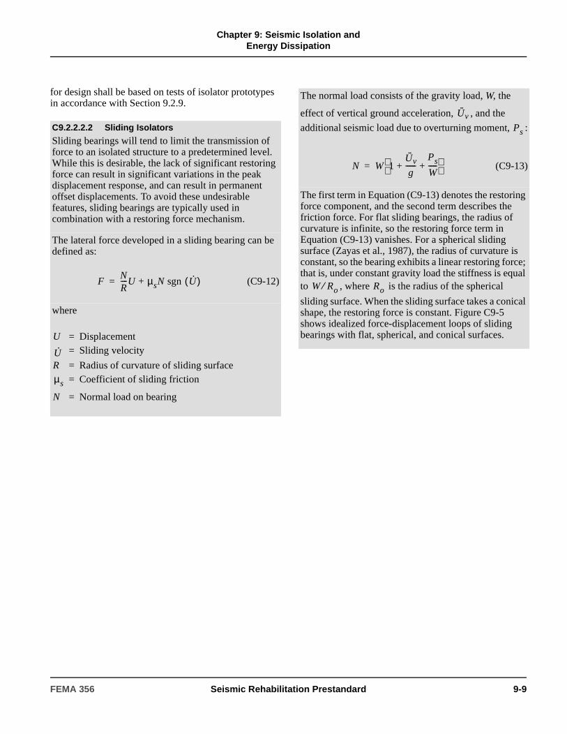
Chapter 9: Seismic Isolation and
Energy Dissipation
for design shall be based on tests of isolator prototypes in accordance with Section 9.2.9.
C9.2.2.2.2 Sliding Isolators
Sliding bearings will tend to limit the transmission of force to an isolated structure to a predetermined level. While this is desirable, the lack of significant restoring force can result in significant variations in the peak displacement response, and can result in permanent offset displacements. To avoid these undesirable features, sliding bearings are typically used in combination with a restoring force mechanism.
The lateral force developed in a sliding bearing can be defined as:
(C9-12)
where
FNR----U + µsN sgn U·( )=
U = Displacement= Sliding velocity
R = Radius of curvature of sliding surface= Coefficient of sliding friction
N = Normal load on bearing
U·
µs
The normal load consists of the gravity load, W, the
effect of vertical ground acceleration, , and the
additional seismic load due to overturning moment, :
(C9-13)
The first term in Equation (C9-13) denotes the restoring force component, and the second term describes the friction force. For flat sliding bearings, the radius of curvature is infinite, so the restoring force term in Equation (C9-13) vanishes. For a spherical sliding surface (Zayas et al., 1987), the radius of curvature is constant, so the bearing exhibits a linear restoring force; that is, under constant gravity load the stiffness is equal to , where is the radius of the spherical
sliding surface. When the sliding surface takes a conical shape, the restoring force is constant. Figure C9-5 shows idealized force-displacement loops of sliding bearings with flat, spherical, and conical surfaces.
U·· v
Ps
N W 1U·· v
g------
Ps
W-----+ +
=
W Ro⁄ Ro
FEMA 356 Seismic Rehabilitation Prestandard 9-9

Chapter 9: Seismic Isolation and
Energy DissipationFigure C9-5 Idealized Force Displacement Loops of Sliding Bearings
Sliding bearings with either a flat or single curvature spherical sliding surface are typically made of PTFE or PTFE-based composites in contact with polished stainless steel. The shape of the sliding surface allows large contact areas that, depending on the materials used, are loaded to average bearing pressures in the range of 7 to 70 MPa. For interfaces with shapes other than flat or spherical, the load needs to be transferred through a bearing as illustrated in Figure C9-5 for the conical sliding surface. Such an arrangement typically results in a very low coefficient of friction.
For bearings with large contact area, and in the absence of liquid lubricants, the coefficient of friction depends on a number of parameters, of which the three most important are the composition of the sliding interface, bearing pressure, and velocity of sliding. For interfaces composed of polished stainless steel in contact with PTFE or PTFE-based composites, the coefficient of sliding friction may be described by
(C9-14)µs fmax - fmax fmin–( ) exp a– U·( )=
where parameters and describe the
coefficient of friction at small and large velocities of sliding and under constant pressure, respectively, all as depicted in Figure C9-6. Parameters , , and a
depend on the bearing pressure, although only the dependency of fmax on pressure is of practical significance. A good approximation to the experimental data (Constantinou et al., 1993b) is
(C9-15)
where the physical significance of parameters
and is as illustrated in Figure C9-6. The term p is
the instantaneous bearing pressure, which is equal to the normal load N computed by Equation (C9-13), divided by the contact area; and ε is a parameter that controls the variation of with pressure.
fmin fmax
fmax fmin
fmax fmaxo fmaxo fmaxp–( ) εptanh–=
fmaxo
fmaxp
fmax
9-10 Seismic Rehabilitation Prestandard FEMA 356

Chapter 9: Seismic Isolation and
Energy Dissipation
9.2.2.3 Modeling of Isolators
9.2.2.3.1 General
If the mechanical characteristics of a seismic isolator are dependent on axial load (due to gravity, earthquake overturning effects, and vertical earthquake shaking), rate of loading (velocity), bilateral deformation, temperature, or aging, then upper- and lower-bound values of stiffness and damping shall be used in multiple analyses of the model to determine the range and sensitivity of response to design parameters.
9.2.2.3.2 Linear Models
The restoring force, F, of an isolator shall be calculated as the product of effective stiffness, keff, and response displacement, D:
(9-1)
The effective stiffness, keff , of an isolator shall be calculated from test data using Equation (9-12). The area enclosed by the force-displacement hysteresis loop shall be used to calculate the effective damping, βeff, of an isolator using Equation (9-13). Effective stiffness and effective damping shall be evaluated at all response displacements of design interest.
Figure C9-6 illustrates another feature of sliding bearings. On initiation of motion, the coefficient of friction exhibits a static or breakaway value, , which
is typically higher than the minimum value . To
demonstrate frictional properties, Figure C9-6 shows the relation between bearing pressure and the friction coefficients , , and of a PTFE-based
composite material in contact with polished stainless steel at normal temperature. These data were compiled from testing of bearings in four different testing programs (Soong and Constantinou, 1994).
Figure C9-6 Coefficient of Friction of PTFE-based Composite in Contact with Polished Stainless Steel at Normal Temperature
Combined elastomeric-sliding isolation systems have been used in buildings in the United States. Japanese engineers have also used elastomeric bearings in combination with mild steel elements that are designed to yield in strong earthquakes and enhance the energy dissipation capability of the isolation system (Kelly, 1988). These mild steel elements exhibit either elasto-plastic behavior or bilinear hysteretic behavior with low post-yielding stiffness. Moreover, fluid viscous energy dissipation devices have been used in combination with elastomeric bearings. The behavior of fluid viscous devices is described in Section 9.3.3.2.3.
µB
fmin
fmax µB fmin
Hybrid seismic isolation systems composed of elastomeric and sliding bearings should be modeled taking into account the likely significant differences in the relationships between vertical displacement as a function of horizontal displacement. The use of elastomeric and sliding isolators in close proximity to one another under vertically stiff structural framing elements (e.g., reinforced concrete shear walls) may be problematic and could result in significant redistributions of gravity loads.
C9.2.2.3.2 Linear Models
Linear procedures use effective stiffness, keff , and effective damping, βeff, to characterize nonlinear properties of isolators.
For linear procedures (see FEMA 274 Section C9.2.3), the seismic isolation system can be represented by an equivalent linearly elastic model. The force in a seismic isolation device is calculated as:
(C9-16)
F keffD=
F keffD=
FEMA 356 Seismic Rehabilitation Prestandard 9-11
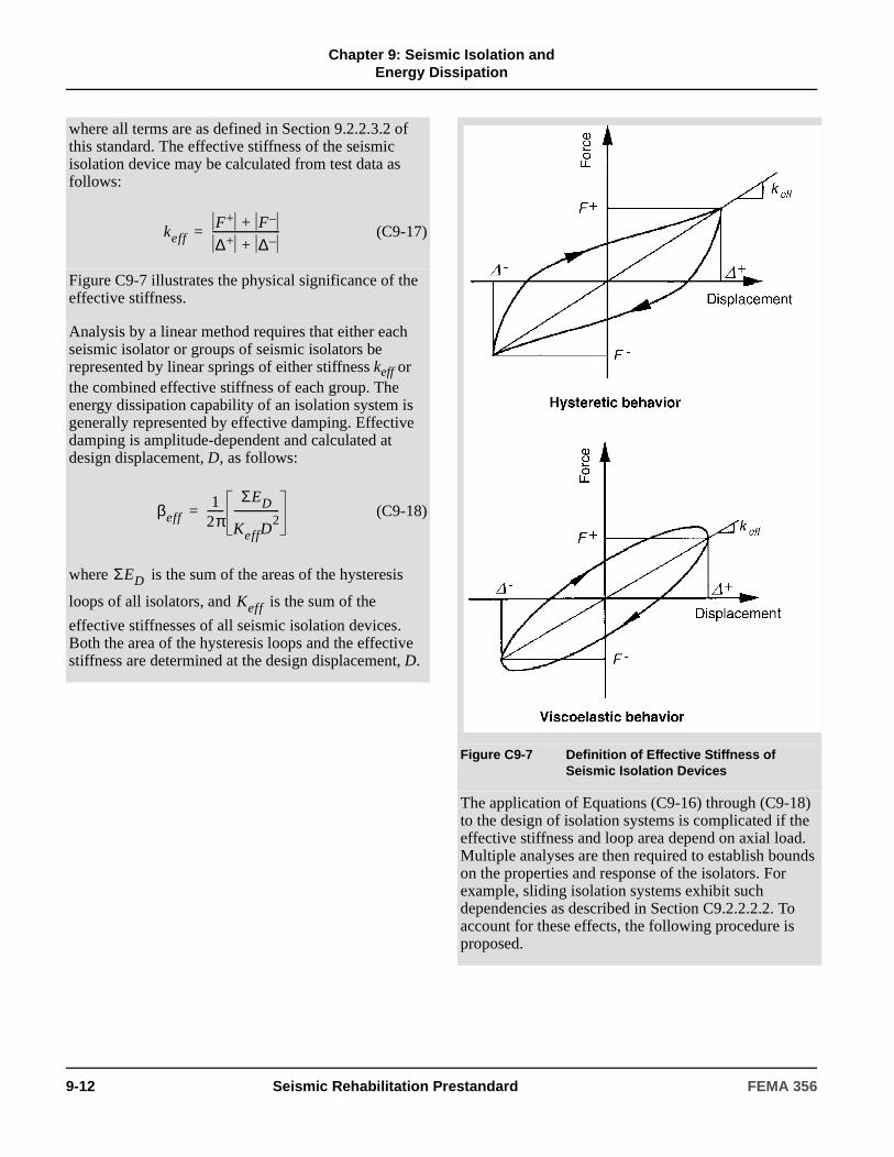
Chapter 9: Seismic Isolation and
Energy Dissipation
where all terms are as defined in Section 9.2.2.3.2 of this standard. The effective stiffness of the seismic isolation device may be calculated from test data as follows:
(C9-17)
Figure C9-7 illustrates the physical significance of the effective stiffness.
Analysis by a linear method requires that either each seismic isolator or groups of seismic isolators be represented by linear springs of either stiffness keff or the combined effective stiffness of each group. The energy dissipation capability of an isolation system is generally represented by effective damping. Effective damping is amplitude-dependent and calculated at design displacement, D, as follows:
(C9-18)
where is the sum of the areas of the hysteresis
loops of all isolators, and is the sum of the
effective stiffnesses of all seismic isolation devices. Both the area of the hysteresis loops and the effective stiffness are determined at the design displacement, D.
keffF+ F–+
∆+ ∆–+-------------------------=
βeff1
2π------
ΣED
KeffD2
-----------------=
ΣED
Keff
Figure C9-7 Definition of Effective Stiffness of Seismic Isolation Devices
The application of Equations (C9-16) through (C9-18) to the design of isolation systems is complicated if the effective stiffness and loop area depend on axial load. Multiple analyses are then required to establish bounds on the properties and response of the isolators. For example, sliding isolation systems exhibit such dependencies as described in Section C9.2.2.2.2. To account for these effects, the following procedure is proposed.
9-12 Seismic Rehabilitation Prestandard FEMA 356
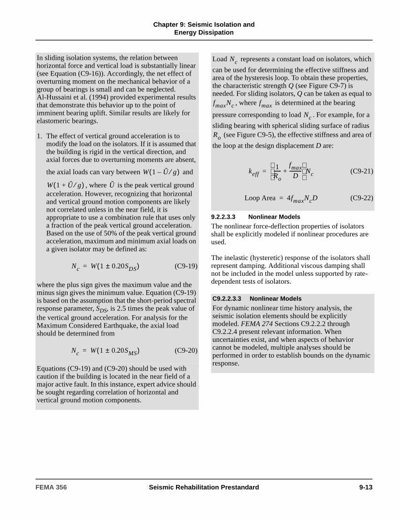
Chapter 9: Seismic Isolation and
Energy Dissipation
9.2.2.3.3 Nonlinear Models
The nonlinear force-deflection properties of isolators shall be explicitly modeled if nonlinear procedures are used.
The inelastic (hysteretic) response of the isolators shall represent damping. Additional viscous damping shall not be included in the model unless supported by rate-dependent tests of isolators.
In sliding isolation systems, the relation between horizontal force and vertical load is substantially linear (see Equation (C9-16)). Accordingly, the net effect of overturning moment on the mechanical behavior of a group of bearings is small and can be neglected. Al-Hussaini et al. (1994) provided experimental results that demonstrate this behavior up to the point of imminent bearing uplift. Similar results are likely for elastomeric bearings.
1. The effect of vertical ground acceleration is to modify the load on the isolators. If it is assumed that the building is rigid in the vertical direction, and axial forces due to overturning moments are absent,
the axial loads can vary between and
, where is the peak vertical ground acceleration. However, recognizing that horizontal and vertical ground motion components are likely not correlated unless in the near field, it is appropriate to use a combination rule that uses only a fraction of the peak vertical ground acceleration. Based on the use of 50% of the peak vertical ground acceleration, maximum and minimum axial loads on a given isolator may be defined as:
(C9-19)
where the plus sign gives the maximum value and the minus sign gives the minimum value. Equation (C9-19) is based on the assumption that the short-period spectral response parameter, SDS, is 2.5 times the peak value of the vertical ground acceleration. For analysis for the Maximum Considered Earthquake, the axial load should be determined from
(C9-20)
Equations (C9-19) and (C9-20) should be used with caution if the building is located in the near field of a major active fault. In this instance, expert advice should be sought regarding correlation of horizontal and vertical ground motion components.
W 1 U·· g⁄–( )
W 1 U·· g⁄+( ) U··
Nc W 1 0.20± SDS( )=
Nc W 1 0.20± SMS( )=
Load represents a constant load on isolators, which
can be used for determining the effective stiffness and area of the hysteresis loop. To obtain these properties, the characteristic strength Q (see Figure C9-7) is needed. For sliding isolators, Q can be taken as equal to
, where is determined at the bearing
pressure corresponding to load . For example, for a
sliding bearing with spherical sliding surface of radius (see Figure C9-5), the effective stiffness and area of
the loop at the design displacement D are:
(C9-21)
(C9-22)
C9.2.2.3.3 Nonlinear Models
For dynamic nonlinear time history analysis, the seismic isolation elements should be explicitly modeled. FEMA 274 Sections C9.2.2.2 through C9.2.2.4 present relevant information. When uncertainties exist, and when aspects of behavior cannot be modeled, multiple analyses should be performed in order to establish bounds on the dynamic response.
Nc
fmaxNc fmax
Nc
Ro
keff1
Ro------
fmax
D----------+
Nc=
Loop Area 4fmaxNcD=
FEMA 356 Seismic Rehabilitation Prestandard 9-13

Chapter 9: Seismic Isolation and
Energy Dissipation
9.2.2.4 Isolation System and Superstructure Modeling
9.2.2.4.1 General
Mathematical models of the isolated building, including the isolation system, the lateral-force-resisting system of the superstructure, other structural components and elements, and connections between the isolation system and the structure, shall meet the requirements of Chapters 2 and 3 and Sections 9.2.2.4.2 and 9.2.2.4.3.
9.2.2.4.2 Isolation System Model
The isolation system shall be modeled using deformation characteristics developed and verified by test in accordance with the requirements of Section 9.2.9.
The isolation system shall be modeled with sufficient detail to:
1. Account for the spatial distribution of isolator units.
2. Calculate translation, in both horizontal directions, and torsion of the structure above the isolation interface, considering the most disadvantageous location of mass eccentricity.
3. Assess overturning/uplift forces on individual isolators.
4. Account for the effects of vertical load, bilateral load, and/or the rate of loading, if the force deflection properties of the isolation system are dependent on one or more of these factors.
5. Assess forces due to P-∆ moments.
6. Account for nonlinear components. Isolation systems with nonlinear components include systems that do not meet the criteria of Section 9.2.3.3.1, Item 2.
9.2.2.4.3 Superstructure Model
The maximum displacement of each floor, the total design displacement, and the total maximum displacement across the isolation system shall be calculated using a model of the isolated building that incorporates the force-deformation characteristics of nonlinear components.
Calculation of design forces and displacements in primary components of the lateral-force-resisting system using linearly elastic models of the isolated structure shall be permitted if both of the following criteria are met:
1. Pseudo-elastic properties assumed for nonlinear isolation system components are based on the maximum effective stiffness of the isolation system.
2. The lateral-force-resisting system remains linearly elastic for the earthquake demand level of interest.
A lateral-force-resisting system that meets both of the following criteria may be classified as linearly elastic:
1. For all deformation-controlled actions, Equation (3-20) is satisfied using an m-factor equal to 1.0.
For simplified nonlinear analysis, each seismic isolation element can be modeled by an appropriate rate-independent hysteretic model. Elastomeric bearings may be modeled as bilinear hysteretic elements as described in FEMA 274 Section C9.2.2.2. Sliding bearings may also be modeled as bilinear hysteretic elements with characteristic strength (see Figure C9-5) given by
(C9-23)
where is determined by either Equation (C9-19) or
Equation (C9-20), and is the coefficient of sliding
friction at the appropriate sliding velocity. The post-yield stiffness can then be determined as:
(C9-24)
where R is as defined in FEMA 274 Section C9.2.2.2.B. The yield displacement Dy in a bilinear hysteretic model of a sliding bearing should be very small, perhaps on the order of 2 mm. Alternatively, a bilinear hysteretic model for sliding bearings may be defined to have an elastic stiffness that is at least 100 times larger than the post-yield stiffness .
Isolation devices that exhibit viscoelastic behavior as shown in Figure C9-7 should be modeled as linearly elastic elements with effective stiffness as
determined by Equation (C9-21).
Q fmaxNc=
Nc
fmax
kp
Nc
R------=
kp
keff
9-14 Seismic Rehabilitation Prestandard FEMA 356
Chapter 9: Seismic Isolation and
Energy Dissipation
2. For all force-controlled actions, Equation (3-21) is satisfied.
9.2.3 General Criteria for Seismic Isolation Design
9.2.3.1 General
The design, analysis, and testing of the isolation system shall be based on the requirements of this section.
9.2.3.1.1 Stability of the Isolation System
The stability of the vertical load-carrying components of the isolation system shall be verified by analysis and test, as required by Section 9.2.9, for a lateral displacement equal to the total maximum displacement computed in accordance with Section 9.2.4.3.5 or Section 9.2.5.1.2, or for the maximum displacement allowed by displacement-restraint devices, if such devices are part of the isolation system.
9.2.3.1.2 Configuration Requirements
The isolated building shall be classified as regular or irregular, as defined in Section 2.4.1.1, based on the structural configuration of the structure above the isolation system.
9.2.3.2 Ground Shaking Criteria
Ground shaking criteria for the Design Earthquake and the Maximum Considered Earthquake shall be established in accordance with Section 1.6 as modified by this section. The design Earthquake Hazard Level shall be user-specified and shall be permitted to be chosen equal to the BSE-1 Earthquake Hazard Level. The Maximum Considered Earthquake shall be taken equal to the BSE-2 Earthquake Hazard Level.
9.2.3.2.1 User-Specified Design Earthquake
For the Design Earthquake, the following ground shaking criteria shall be established:
1. Short period spectral response acceleration parameter, SXS and spectral response acceleration parameter at 1.0 second, SX1, in accordance with Section 1.6.1.4.
2. Five-percent-damped response spectrum of the design earthquake (when a response spectrum is required for linear procedures by Section 9.2.3.3.2, or to define acceleration time histories).
3. At least three acceleration time histories compatible with the design earthquake spectrum (when acceleration time histories are required for nonlinear procedures by Section 9.2.3.3.3).
9.2.3.2.2 Maximum Considered Earthquake
For the BSE-2, the following ground shaking criteria shall be established:
1. Short period spectral response acceleration parameter, SXS and spectral response acceleration parameter at 1.0 second, SX1, in accordance with Section 1.6.1.4.
2. Five-percent-damped site-specific response spectrum of the BSE-2 (when a response spectrum is required for linear procedures by Section 9.2.3.3.2, or to define acceleration time histories).
3. At least three acceleration time histories compatible with the BSE-2 spectrum (when acceleration time histories are required for nonlinear procedures by Section 9.2.3.3.3).
9.2.3.3 Selection of Analysis Procedure
9.2.3.3.1 Linear Procedures
Linear procedures shall be permitted for design of seismically isolated buildings, provided the following criteria are met.
1. The building is located on Soil Profile Type A, B, C, or D; or E if for BSE-2.
2. The isolation system meets all of the following criteria:
2.1. The effective stiffness of the isolation system at the design displacement is greater than one-third of the effective stiffness at 20% of the design displacement.
C9.2.3.1 General
Criteria for the seismic isolation of buildings are divided into two sections:
1. Rehabilitation of the building.
2. Design, analysis, and testing of the isolation system.
S1 0.6≥
FEMA 356 Seismic Rehabilitation Prestandard 9-15

Chapter 9: Seismic Isolation and
Energy Dissipation
2.2. The isolation system is capable of producing a restoring force as specified in Section 9.2.7.2.4.
2.3. The isolation system has force-deflection properties that are independent of the rate of loading.
2.4. The isolation system has force-deflection properties that are independent of vertical load and bilateral load.
2.5. When considering analysis procedures, for the BSE-2, the isolation system does not limit BSE-2 displacement to less than the ratio of the design spectral response acceleration at one second (SX1) for the BSE-2 to that for the Design Earthquake times the total design displacement.
3. The structure above the isolation system exhibits global elastic behavior for the earthquake motions under consideration.
9.2.3.3.2 Response Spectrum Analysis
Response spectrum analysis shall be used for design of seismically isolated buildings that meet any of the following criteria.
1. The building is over 65 feet (19.8 meters) in height.
2. The effective period of the structure, TM, is greater than three seconds.
3. The effective period of the isolated structure, TD, is less than or equal to three times the elastic, fixed-base period of the structure above the isolation system.
4. The structure above the isolation system is irregular in configuration.
9.2.3.3.3 Nonlinear Procedures
Nonlinear procedures shall be used for design of seismic-isolated buildings for which any of the following conditions apply:
1. The structure above the isolation system is nonlinear for the earthquake motions under consideration.
2. The isolation system does not meet all of the criteria of Section 9.2.3.3.1.
Nonlinear acceleration time history analysis shall be performed for the design of seismically isolated buildings for which conditions (1) and (2) apply.
C9.2.3.3 Selection of Analysis Procedure
Linear procedures include prescriptive formulas and Response Spectrum Analysis. Linear procedures based on formulas (similar to the seismic-coefficient equation required for design of fixed-base buildings) prescribe peak lateral displacement of the isolation system, and define “minimum” design criteria that may be used for design of a very limited class of isolated structures (without confirmatory dynamic analyses). These simple formulas are useful for preliminary design and provide a means of expeditious review of more complex calculations.
Response Spectrum Analysis is recommended for design of isolated structures that have either (1) a tall or otherwise flexible superstructure, or (2) an irregular superstructure. For most buildings, Response Spectrum Analysis will not predict significantly different displacements of the isolation system than those calculated by prescriptive formulas, provided both calculations are based on the same effective stiffness and damping properties of the isolation system. The real benefit of Response Spectrum Analysis is not in the prediction of isolation system response, but rather in the calculation and distribution of forces in the superstructure. Response Spectrum Analysis permits the use of more detailed models of the superstructure that better estimate forces and deformations of components and elements considering flexibility and irregularity of the structural system.
Nonlinear procedures include the Nonlinear Static Procedure (NSP) and the Nonlinear Dynamic Procedure (NDP). The NSP is a static pushover procedure, and the NDP is based on nonlinear Time History Analysis. The NSP or the NDP is required for isolated structures that do not have essentially linearly elastic superstructures (during BSE-2 demand). In this case, the superstructure would be modeled with nonlinear elements and components.
9-16 Seismic Rehabilitation Prestandard FEMA 356

Chapter 9: Seismic Isolation and
Energy Dissipation
9.2.4 Linear Procedures
9.2.4.1 General
Seismically isolated buildings for which linear analysis procedures are selected based on the criteria of Section 9.2.3.3 shall be designed and constructed to resist the earthquake displacements and forces specified in this section, at a minimum.
9.2.4.2 Deformation Characteristics of the Isolation System
The deformation characteristics of the isolation system shall be based on tests performed in accordance with Section 9.2.9.
The deformation characteristics of the isolation system shall explicitly include the effects of the wind-restraint and tie-down systems, and supplemental energy-dissipation devices, if such systems and devices are used to meet the design requirements of this standard.
9.2.4.3 Minimum Lateral Displacements
9.2.4.3.1 Design Displacement
The isolation system shall be designed and constructed to withstand, as a minimum, lateral earthquake displacements that act in the direction of each of the main horizontal axes of the structure in accordance with Equation (9-2):
(9-2)
where:
SX1 is evaluated for the Design Earthquake.
9.2.4.3.2 Effective Period at the Design Displacement
The effective period, TD, of the isolated building at the design displacement shall be determined using the deformation characteristics of the isolation system in accordance with Equation (9-3):
(9-3)
9.2.4.3.3 Maximum Displacement
The maximum displacement of the isolation system, DM, in the most critical direction of horizontal response shall be calculated in accordance with Equation (9-4):
(9-4)
where:
Time History Analysis is required for isolated structures on very soft soil (i.e., Soil Profile Type E when shaking is strong, or Soil Profile Type F) that could shake the building with a large number of cycles of long-period motion, and for buildings with isolation systems that are best characterized by nonlinear models. Such isolation systems include:
1. Systems with more than about 30% effective damping (because high levels of damping can significantly affect higher-mode response of the superstructure).
2. Systems that lack significant restoring force (because these systems may not stay centered during earthquake shaking).
3. Systems that are expected to exceed the sway-space clearance with adjacent structures (because impact with adjacent structures could impose large demands on the superstructure).
4. Systems that are rate- or load-dependent (because their properties will vary during earthquake shaking).
For the types of isolation systems described above, appropriate nonlinear properties must be used to model isolators. Linear properties could be used to model the superstructure, provided the superstructure’s response is essentially linearly elastic for BSE-2 demand.
The restrictions placed on the use of linear procedures effectively suggest that nonlinear procedures be used for virtually all isolated buildings. However, lower-bound limits on isolation system design displacement and force are specified by this standard as a percentage of the demand prescribed by the linear formulas, even when dynamic analysis is used as the basis for design. These lower-bound limits on key design attributes ensure consistency in the design of isolated structures and serve as a “safety net” against gross underdesign.
DDg
4π2---------
SX1TD
BD1----------------=
TD 2π WKDming------------------=
DMg
4π2---------
SX1TM
BM1----------------=
FEMA 356 Seismic Rehabilitation Prestandard 9-17
Chapter 9: Seismic Isolation and
Energy Dissipation
SX1 is evaluated for the BSE-2.
9.2.4.3.4 Effective Period at the Maximum Displacement
The effective period, TM, of the isolated building at the maximum displacement shall be determined using the deformation characteristics of the isolation system in accordance with Equation (9-5):
(9-5)
9.2.4.3.5 Total Displacement
The total design displacement, DTD, and the total maximum displacement, DTM, of components of the isolation system shall include additional displacement due to actual and accidental torsion calculated considering the spatial distribution of the effective stiffness of the isolation system at the design displacement and the most disadvantageous location of mass eccentricity.
The total design displacement, DTD, and the total maximum displacement, DTM, of components of an isolation system with a uniform spatial distribution of effective stiffness at the design displacement shall be taken as not less than that prescribed by Equations (9-6) and (9-7):
(9-6)
(9-7)
A value for the total maximum displacement, DTM, less than the value prescribed by Equation (9-7), but not less than 1.1 times DM, shall be permitted, provided the isolation system is shown by calculation to be configured to resist torsion.
9.2.4.4 Minimum Lateral Forces
9.2.4.4.1 Isolation System and Structural Components and Elements at or below the Isolation System
The isolation system, the foundation, and all other structural components and elements below the isolation
system shall be designed and constructed to withstand a minimum lateral seismic force, Vb, prescribed by Equation (9-8):
(9-8)
9.2.4.4.2 Structural Components and Elements above the Isolation System
The components and elements above the isolation system shall be designed and constructed to resist a minimum lateral seismic force, Vs , equal to the value of Vb, prescribed by Equation (9-8).
9.2.4.4.3 Limits on Vs
The value of Vs shall be taken as not less than the following:
1. The base shear corresponding to the design wind load.
2. The lateral seismic force required to fully activate the isolation system factored by 1.5.
9.2.4.4.4 Vertical Distribution of Force
The total force, Vs, shall be distributed over the height of the structure above the isolation interface in accordance with Equation (9-9):
(9-9)
At each level designated as x, the force Fx shall be applied over the area of the building in accordance with the weight, wx, distribution at that level, hx. Response of structural components and elements shall be calculated as the effect of the force Fx applied at the appropriate levels above the base.
TM 2π WKMming-------------------=
DTD DD 1 y12e
b2
d2
+-----------------+=
DTM DM 1 y12e
b2
d2
+-----------------+=
C9.2.4.4.3 Limits on Vs
Examples of lateral seismic forces required to fully activate the isolation system include the yield level of a softening system, the ultimate capacity of a sacrificial wind-restraint system, or the break-away friction level of a sliding system.
Vb KDmaxDD=
Fx
Vswxhx
wihi
n
∑---------------------=
9-18 Seismic Rehabilitation Prestandard FEMA 356

Chapter 9: Seismic Isolation and
Energy Dissipation
9.2.4.5 Response Spectrum Analysis
9.2.4.5.1 Earthquake Input
The Design Earthquake spectrum shall be used to calculate the total design displacement of the isolation system and the lateral forces and displacements of the isolated building. The BSE-2 spectrum shall be used to calculate the total maximum displacement of the isolation system.
9.2.4.5.2 Modal Damping
Response spectrum analysis shall be performed, using a damping value for isolated modes equal to the effective damping of the isolation system, or 30% of critical, whichever is less. The damping value assigned to higher modes of response shall be consistent with the material type and stress level of the superstructure.
9.2.4.5.3 Combination of Earthquake Directions
Response spectrum analysis used to determine the total design displacement and total maximum displacement shall include simultaneous excitation of the model by 100% of the most critical direction of ground motion, and not less than 30% of the ground motion in the orthogonal axis. The maximum displacement of the isolation system shall be calculated as the vector sum of the two orthogonal displacements.
9.2.4.5.4 Scaling of Results
If the total design displacement determined by response spectrum analysis is found to be less than the value of DTD prescribed by Equation (9-6), or if the total maximum displacement determined by response spectrum analysis is found to be less than the value of DTM prescribed by Equation (9-7), then all response parameters, including component actions and deformations, shall be adjusted upward proportionally to the DTD value, or the DTM value, whichever is greater, and used for design.
9.2.4.6 Design Forces and Deformations
Components and elements of the building shall be designed for forces and displacements estimated by linear procedures using the acceptance criteria of Section 3.4.2.2, except that deformation-controlled components and elements shall be designed using component m-factors equal to or less than 1.5.
9.2.5 Nonlinear Procedures
Seismically isolated buildings evaluated using nonlinear procedures shall be represented by three-
dimensional models that incorporate the nonlinear characteristics of both the isolation system and the structure above the isolation system.
9.2.5.1 Nonlinear Static Procedure
9.2.5.1.1 General
The Nonlinear Static Procedure (NSP) for seismically isolated buildings shall be based on the criteria of Section 3.3.3, except that the target displacement and pattern of applied lateral load shall be based on the criteria given in Sections 9.2.5.1.2 and 9.2.5.1.3, respectively.
9.2.5.1.2 Target Displacement
In each principal direction, the building model shall be pushed to the Design Earthquake target displacement,
, and to the BSE-2 target displacement, , as
defined by Equations (9-10) and (9-11):
(9-10)
(9-11)
where Te is the effective period of the structure above the isolation interface on a fixed base as prescribed by Equation (3-14). The target displacements, and ,
shall be evaluated at a control node that is located at the center of mass of the first floor above the isolation interface.
9.2.5.1.3 Lateral Load Pattern
The pattern of applied lateral load shall be proportional to the distribution of the product of building mass and the deflected shape of the isolated mode of response at the target displacement.
9.2.5.2 Nonlinear Dynamic Procedure
9.2.5.2.1 General
The Nonlinear Dynamic Procedure (NDP) for seismically isolated buildings shall be based on the nonlinear procedure requirements of Section 3.3.4,
D ′D D ′M
D ′DDD
1Te
TD-------
2
+
-----------------------------=
D ′MDM
1Te
TM-------
2
+
-----------------------------=
D ′D D ′M
FEMA 356 Seismic Rehabilitation Prestandard 9-19
Chapter 9: Seismic Isolation and
Energy Dissipation
except that results shall be scaled for design based on the criteria given in the following section.
9.2.5.2.2 Scaling of Results
If the design displacement determined by time-history analysis is less than the value of prescribed by
Equation (9-10), or if the maximum displacement determined by response spectrum analysis is found to be less than the value of prescribed by Equation
(9-11), then all response parameters, including component actions and deformations, shall be adjusted upward proportionally to the value or the
value, whichever is greater, and used for design.
9.2.5.3 Design Forces and Deformations
Components and elements of the building shall be designed for the forces and deformations estimated by nonlinear procedures using the acceptance criteria of Section 3.4.3.2.
9.2.6 Nonstructural Components
9.2.6.1 General
Permanent nonstructural components and the attachments to them shall be designed to resist seismic forces and displacements as given in this section and the applicable requirements of Chapter 11.
9.2.6.2 Forces and Displacements
9.2.6.2.1 Components and Elements at or above the Isolation Interface
Nonstructural components, or portions thereof, that are at or above the isolation interface, shall be designed to resist a total lateral seismic force equal to the maximum dynamic response of the element or component under consideration.
EXCEPTION: Design of elements of seismically isolated structures and nonstructural components, or portions thereof, to resist the total lateral seismic force as required for conventional fixed-base buildings by Chapter 11, shall be permitted.
9.2.6.2.2 Components and Elements that Cross the Isolation Interface
Nonstructural components, or portions thereof, that cross the isolation interface shall be designed to withstand the total maximum (horizontal) displacement and maximum vertical displacement of the isolation
system at the total maximum (horizontal) displacement. Components and elements that cross the isolation interface shall not restrict displacement of the isolated building or otherwise compromise the Rehabilitation Objectives of the building.
9.2.6.2.3 Components and Elements below the Isolation Interface
Nonstructural components, or portions thereof, that are below the isolation interface shall be designed and constructed in accordance with the requirements of Chapter 11.
9.2.7 Detailed System Requirements
9.2.7.1 General
The isolation system and the structural system shall comply with the detailed system requirements specified in Section 9.2.7.2 and 9.2.7.3, respectively.
9.2.7.2 Isolation System
9.2.7.2.1 Environmental Conditions
In addition to the requirements for vertical and lateral loads induced by wind and earthquake, the isolation system shall be designed with consideration given to other environmental conditions, including aging effects, creep, fatigue, operating temperature, and exposure to moisture or damaging substances.
9.2.7.2.2 Wind Forces
Isolated buildings shall resist design wind loads at all levels above the isolation interface in accordance with the applicable wind design provisions. At the isolation interface, a wind-restraint system shall be provided to limit lateral displacement in the isolation system to a value equal to that required between floors of the structure above the isolation interface.
9.2.7.2.3 Fire Resistance
Fire resistance rating for the isolation system shall be consistent with the requirements of columns, walls, or other such elements of the building.
9.2.7.2.4 Lateral Restoring Force
The isolation system shall be configured to produce either a restoring force such that the lateral force at the total design displacement is at least 0.025W greater than the lateral force at 50% of the total design displacement, or a restoring force of not less than 0.05W at all displacements greater than 50% of the total design displacement.
D ′D
D ′M
D ′D D ′M
9-20 Seismic Rehabilitation Prestandard FEMA 356

Chapter 9: Seismic Isolation and
Energy Dissipation
EXCEPTION: The isolation system need not be configured to produce a restoring force, as required above, provided the isolation system is capable of remaining stable under full vertical load and accommodating a total maximum displacement equal to the greater of either 3.0 times the total design displacement or 36 SX1 inches, where SX1 is calculated for the BSE-2.
9.2.7.2.5 Displacement Restraint
Configuration of the isolation system to include a displacement restraint that limits lateral displacement due to the BSE-2 to less than the ratio of the design spectral response acceleration parameter at one second (SX1) for the BSE-2 to that for the Design Earthquake times the total design displacement shall be permitted, provided that the seismically isolated building is designed in accordance with the following criteria when more stringent than the requirements of Section 9.2.3.
1. BSE-2 response is calculated in accordance with the dynamic analysis requirements of Section 9.2.5, explicitly considering the nonlinear characteristics of the isolation system and the structure above the isolation system.
2. The ultimate capacity of the isolation system, and structural components and elements below the isolation system, shall exceed the force and displacement demands of the BSE-2.
3. The structure above the isolation system is checked for stability and ductility demand of the BSE-2.
4. The displacement restraint does not become effective at a displacement less than 0.75 times the total design displacement, unless it is demonstrated by analysis that earlier engagement does not result in unsatisfactory performance.
9.2.7.2.6 Vertical Load Stability
Each component of the isolation system shall be designed to be stable under the full maximum vertical load, 1.2QD + QL + |QE|, and the minimum vertical load, 0.8QD - |QE|, at a horizontal displacement equal to the total maximum displacement. The earthquake vertical load on an individual isolator unit, QE, shall be based on peak building response due to the BSE-2.
9.2.7.2.7 Overturning
The factor of safety against global structural overturning at the isolation interface shall be not less than 1.0 for required load combinations. All gravity and seismic loading conditions shall be investigated. Seismic forces for overturning calculations shall be based on the BSE-2, and the vertical restoring force shall be based on the building’s weight, W, above the isolation interface.
Local uplift of individual components and elements shall be permitted, provided the resulting deflections do not cause overstress or instability of the isolator units or other building components and elements. A tie-down system to limit local uplift of individual components and elements shall be permitted, provided that the seismically isolated building is designed in accordance with the following criteria when more stringent than the requirements of Section 9.2.3.
1. BSE-2 response is calculated in accordance with the dynamic analysis requirements of Section 9.2.5, explicitly considering the nonlinear characteristics of the isolation system and the structure above the isolation system.
2. The ultimate capacity of the tie-down system exceeds the force and displacement demands of the BSE-2.
3. The isolation system is designed and shown by test to be stable (Section 9.2.9.2.4) for BSE-2 loads that include additional vertical load due to the tie-down system.
9.2.7.2.8 Inspection and Replacement
Access for inspection and replacement of all components and elements of the isolation system shall be provided.
9.2.7.2.9 Manufacturing Quality Control
A manufacturing quality control testing program for isolator units shall be established by the engineer responsible for the structural design.
9.2.7.3 Structural System
9.2.7.3.1 Horizontal Distribution of Force
A horizontal diaphragm or other structural components and elements shall provide continuity above the isolation interface. The diaphragm or other structural components and elements shall have adequate strength
FEMA 356 Seismic Rehabilitation Prestandard 9-21

Chapter 9: Seismic Isolation and
Energy Dissipation
and ductility to transmit forces (due to non-uniform ground motion) calculated in accordance with this section from one part of the building to another, and have sufficient stiffness to effect rigid diaphragm response above the isolation interface.
9.2.7.3.2 Building Separations
Separations between the isolated building and surrounding retaining walls or other fixed obstructions shall be not less than the total design displacement.
9.2.8 Design Review
9.2.8.1 General
A review of the design of the isolation system and related test programs shall be performed by an independent engineering team, including persons experienced in seismic analysis methods and the theory and application of seismic isolation.
9.2.8.2 Isolation System
Isolation system design review shall include the following:
1. Site-specific seismic criteria, including site-specific spectra and ground motion time history, and all other design criteria developed specifically for the project.
2. Preliminary design, including the determination of the total design and total maximum displacement of the isolation system, and the lateral force design level.
3. Isolation system prototype testing in accordance with Section 9.2.9.
4. Final design of the isolated building and supporting analyses.
5. Isolation system quality control testing in accordance with Section 9.2.7.2.9.
9.2.9 Isolation System Testing and Design Properties
9.2.9.1 General
The deformation characteristics and damping values of the isolation system used in the design and analysis of seismically isolated structures shall be based on the following tests of a selected sample of the components prior to construction.
The isolation system components to be tested shall include isolators and components of the wind restraint system and supplemental energy dissipation devices if such components and devices are used in the design.
The tests specified in this section establish design properties of the isolation system, and shall not be considered as satisfying the manufacturing quality control testing requirements of Section 9.2.7.2.9.
9.2.9.2 Prototype Tests
9.2.9.2.1 General
Prototype tests shall be performed separately on two full-size specimens of each type and size of isolator of the isolation system. The test specimens shall include components of the wind restraint system, as well as individual isolators, if such components are used in the design. Supplementary energy dissipation devices shall be tested in accordance with Section 9.3.8. Specimens tested shall not be used for construction unless approved by the engineer responsible for the structural design.
9.2.9.2.2 Record
For each cycle of tests, the force-deflection and hysteretic behavior of the test specimen shall be recorded.
9.2.9.2.3 Sequence and Cycles
The following sequence of tests shall be performed for the prescribed number of cycles at a vertical load equal to the average QD + 0.5QL on all isolators of a common type and size:
1. Twenty fully reversed cycles of loading at a lateral force corresponding to the wind design force.
2. Three fully reversed cycles of loading at each of the following displacements: 0.25DD, 0.50DD, 1.0DD, and 1.0DM.
3. Three fully reversed cycles at the total maximum displacement, 1.0DTM.
4. 30SX1 / SXSBD1, but not less than 10, fully reversed cycles of loading at the design displacement, 1.0DD. SX1 and SXS shall be evaluated for the Design Earthquake.
9-22 Seismic Rehabilitation Prestandard FEMA 356
Chapter 9: Seismic Isolation and
Energy Dissipation
9.2.9.2.4 Vertical Load-Carrying Isolators
If an isolator is also a vertical-load-carrying element, then Item 2 of the sequence of cyclic tests specified in Section 9.2.9.2.3 shall be performed for two additional vertical load cases:
1. 1.2QD + 0.5QL + |QE|
2. 0.8QD - |QE|
where D, L, and E refer to dead, live, and earthquake loads. QD and QL are as defined in Section 3.2.8. The vertical test load on an individual isolator unit shall include the load increment QE due to earthquake overturning, and shall be equal to or greater than the peak earthquake vertical force response corresponding to the test displacement being evaluated. In these tests, the combined vertical load shall be taken as the typical or average downward force on all isolators of a common type and size.
9.2.9.2.5 Isolators Dependent on Loading Rates
If the force-deflection properties of the isolators are dependent on the rate of loading, then each set of tests specified in Sections 9.2.9.2.3 and 9.2.9.2.4 shall be performed dynamically at a frequency equal to the inverse of the effective period, TD, of the isolated structure.
EXCEPTION: If reduced-scale prototype specimens are used to quantify rate-dependent properties of isolators, the reduced-scale prototype specimens shall be of the same type and material and be manufactured with the same processes and quality as full-scale prototypes, and shall be tested at a frequency that represents full-scale prototype loading rates.
The force-deflection properties of an isolator shall be considered to be dependent on the rate of loading if there is greater than a plus or minus 10% difference in the effective stiffness at the design displacement (1) when tested at a frequency equal to the inverse of the effective period of the isolated structure and (2) when tested at any frequency in the range of 0.1 to 2.0 times the inverse of the effective period of the isolated structure.
9.2.9.2.6 Isolators Dependent on Bilateral Load
If the force-deflection properties of the isolators are dependent on bilateral load, then the tests specified in
Sections 9.2.9.2.3 and 9.2.9.2.5 shall be augmented to include bilateral load at the following increments of the total design displacement: 0.25 and 1.0; 0.50 and 1.0; 0.75 and 1.0; and 1.0 and 1.0.
EXCEPTION: If reduced-scale prototype specimens are used to quantify bilateral-load-dependent properties, then such scaled specimens shall be of the same type and material, and manufactured with the same processes and quality as full-scale prototypes.
The force-deflection properties of an isolator shall be considered to be dependent on bilateral load, if the bilateral and unilateral force-deflection properties have greater than a plus or minus 15% difference in effective stiffness at the design displacement.
9.2.9.2.7 Maximum and Minimum Vertical Load
Isolators that carry vertical load shall be statically tested for the maximum and minimum vertical load, at the total maximum displacement. In these tests, the combined vertical loads of 1.2QD + 1.0QL + |QE| shall be taken as the maximum vertical force, and the combined vertical load of 0. 8QD - |QE| shall be taken as the minimum vertical force, on any one isolator of a common type and size. The earthquake vertical load on an individual isolator, QE, shall be based on peak building response due to the BSE-2.
9.2.9.2.8 Sacrificial Wind-Restraint Systems
If a sacrificial wind-restraint system is part of the isolation system, then the ultimate capacity shall be established by testing in accordance with this section.
9.2.9.2.9 Testing Similar Units
Prototype tests need not be performed if an isolator unit, when compared to another tested unit, complies with the following criteria:
1. Is of similar dimensional characteristics.
2. Is of the same type and materials.
3. Is fabricated using identical manufacturing and quality control procedures.
The testing exemption shall be approved by the review team specified in Section 9.2.8.
FEMA 356 Seismic Rehabilitation Prestandard 9-23

Chapter 9: Seismic Isolation and
Energy Dissipation
9.2.9.3 Determination of Force-Deflection Characteristics
The force-deflection characteristics of the isolation system shall be based on the cyclic load testing of isolator prototypes specified in Section 9.2.9.2.3.
As required, the effective stiffness of an isolator unit, keff, shall be calculated for each cycle of deformation by Equation (9-12):
(9-12)
where and are the positive and negative forces at
positive and negative test displacements, ∆+ and ∆–, respectively.
As required, the effective damping of an isolator unit, βeff, shall be calculated for each cycle of deformation by Equation (9-13):
(9-13)
where the energy dissipated per cycle of loading, ELoop, and the effective stiffness, keff, are based on test
displacements, ∆+ and ∆–.
9.2.9.4 System Adequacy
The performance of the test specimens shall be assessed as adequate if the following conditions are satisfied.
1. The force-deflection plots of all tests specified in Section 9.2.9.2 have a nonnegative incremental force-carrying capacity.
2. For each increment of test displacement specified in Section 9.2.9.2.3, Item 2, and for each vertical load case specified in Section 9.2.9.2.3, the following criteria are met:
2.1. There is no greater than a plus or minus 15% difference between the effective stiffness at each of the three cycles of test and the average value of effective stiffness for each test specimen.
2.2. There is no greater than a 15% difference in the average value of effective stiffness of the two test specimens of a common type and size of the isolator unit over the required three cycles of test.
3. For each specimen there is no greater than a plus or minus 20% change in the initial effective stiffness of each test specimen over the 30SX1/ SXSBD1, but not less than 10, cycles of the test specified in Section 9.2.9.2.3, Item 3. SX1 and SXS shall be evaluated for the Design Earthquake.
4. For each specimen there is no greater than a 20% decrease in the initial effective damping over the 30SX1/ SXSBD1, but not less than 10, cycles of the test specified in Section 9.2.9.2.3, Item 4. SX1 and SXS shall be evaluated for the Design Earthquake.
5. All specimens of vertical-load-carrying elements of the isolation system remain stable at the total maximum displacement for static load as prescribed in Section 9.2.9.2.6.
6. The effective stiffness and effective damping of test specimens fall within the limits specified by the engineer responsible for structural design.
9.2.9.5 Design Properties of the Isolation System
9.2.9.5.1 Maximum and Minimum Effective Stiffness
At the design displacement, the maximum and minimum effective stiffness of the isolation system, KDmax and KDmin, shall be based on the cyclic tests of Section 9.2.9.2 and calculated by Equations (9-14) and (9-15):
(9-14)
(9-15)
At the maximum displacement, the maximum and minimum effective stiffness of the isolation system shall be based on cyclic tests of Section 9.2.9.2 and calculated by Equations (9-16) and (9-17):
keffF
+F
–+
∆+ ∆–+
-------------------------=
F+
F–
βeff2π---
ELoop
keff ∆+ ∆–+( )
2-----------------------------------------=
KDmax
FD+
max FD–
max∑+∑2DD
---------------------------------------------------------=
KDmin
FD+
min FD–
min∑+∑2DD
--------------------------------------------------------=
9-24 Seismic Rehabilitation Prestandard FEMA 356

Chapter 9: Seismic Isolation and
Energy Dissipation
(9-16)
(9-17)
9.2.9.5.2 Effective Damping
At the design displacement, the effective damping of the isolation system, βD, shall be based on the cyclic tests of Section 9.2.9.2 and calculated by Equation (9-18):
(9-18)
In Equation (9-18), the total energy dissipated in the isolation system per displacement cycle, ΣED, shall be taken as the sum of the energy dissipated per cycle in all
isolators measured at test displacements, ∆+ and ∆–, that are equal in magnitude to the design displacement, DD.
At the maximum displacement, the effective damping of the isolation system, βM, shall be based on the cyclic tests of Section 9.2.9.2 and calculated by Equation (9-19):
(9-19)
In Equation (9-19), the total energy dissipated in the isolation system per displacement cycle, ΣEM, shall be taken as the sum of the energy dissipated per cycle in all
isolators measured at test displacements, ∆+ and ∆–, that are equal in magnitude to the maximum displacement, DM.
9.3 Passive Energy Dissipation Systems
9.3.1 General Requirements
Passive energy dissipation systems classified as either displacement-dependent, velocity-dependent, or other, as defined in Section 9.3.3, shall comply with the requirements of Section 9.3. Linear and nonlinear analyses shall be performed, as required, in accordance with Section 9.3.4 and 9.3.5, respectively. Additional requirements for passive energy dissipation systems, as defined in Section 9.3.6, shall be met. Passive energy dissipation systems shall be reviewed and tested in accordance with Sections 9.3.7 and 9.3.8, respectively.
The energy dissipation devices shall be designed with consideration given to environmental conditions including wind, aging effects, creep, fatigue, ambient temperature, operating temperature, and exposure to moisture or damaging substances.
The mathematical model of the rehabilitated building shall include the plan and vertical distribution of the energy dissipation devices. Analyses shall account for the dependence of the devices on excitation frequency, ambient and operating temperature, velocity, sustained loads, and bilateral loads. Multiple analyses of the building shall be conducted to bound the effects of each varying mechanical characteristic of the devices.
Energy dissipation devices shall be capable of sustaining larger displacements for displacement-dependent devices and larger velocities for velocity-dependent devices than the maximum calculated for the BSE-2 in accordance with the following criteria:
1. If four or more energy dissipation devices are provided in a given story of a building in one principal direction of the building, with a minimum of two devices located on each side of the center of stiffness of the story in the direction under consideration, all energy dissipation devices shall be capable of sustaining displacements equal to 130% of the maximum calculated displacement in the device in the BSE-2. A velocity-dependent device as described in Section 9.3.3 shall be capable of sustaining the force associated with a velocity equal to 130% of the maximum calculated velocity for that device in the BSE-2.
KMmax
FM+
max FM–
max∑+∑2DM
----------------------------------------------------------=
KMmin
FM+
min FM–
min∑+∑2DM
---------------------------------------------------------=
βD1
2π------
ED∑KDmaxDD
2------------------------=
βM1
2π------
EM∑KMmaxDM
2-------------------------=
FEMA 356 Seismic Rehabilitation Prestandard 9-25
Chapter 9: Seismic Isolation and
Energy Dissipation
2. If fewer than four energy dissipation devices are provided in a given story of a building in one principal direction of the building, or fewer than two devices are located on each side of the center of stiffness of the story in the direction under consideration, all energy dissipation devices shall be capable of sustaining displacements equal to 200% of the maximum calculated displacement in the device in the BSE-2. A velocity-dependent device shall be capable of sustaining the force associated with a velocity equal to 200% of the maximum calculated velocity for that device in the BSE-2.
The components and connections transferring forces between the energy dissipation devices shall be designed to remain linearly elastic for the forces described in items 1 or 2 above.
9.3.2 Implementation of Energy Dissipation Devices
Energy dissipation devices shall be implemented in accordance with requirements specified in Chapters 1 through 3 but as modified in the subsequent sections of this chapter.
9.3.3 Modeling of Energy Dissipation Devices
Displacement-dependent devices shall include devices that exhibit either rigid-plastic (friction devices), bilinear (metallic yielding devices), or trilinear hysteresis. The response of displacement-dependent devices shall be independent of velocity and frequency of excitation. Velocity-dependent devices shall include solid and fluid viscoelastic devices, and fluid viscous devices. Devices not classified as displacement- or velocity-dependent shall be classified as “other.”
Models of the energy dissipation system shall include the stiffness of structural components that are part of the load path between energy dissipation devices and the ground and whose flexibility affects the performance of
C9.3.1 General Requirements
The increase in displacement (and velocity) capacity is dependent on the level of redundancy in the supplemental damping system.
Passive energy dissipation is an emerging technology that enhances the performance of the building by adding damping (and in some cases, stiffness) to the building. The primary use of energy dissipation devices is to reduce earthquake displacement of the structure. Energy dissipation devices will also reduce force in the structure—provided the structure is responding elastically—but would not be expected to reduce force in structures that are responding beyond yield.
For most applications, energy dissipation provides an alternative approach to conventional stiffening and strengthening schemes, and would be expected to achieve comparable performance levels. In general, these devices would be expected to be good candidates for projects that have a target Building Performance Level of Life Safety or perhaps Immediate Occupancy, but would be expected to have only limited applicability to projects with a target Building Performance Level of Collapse Prevention.
Other objectives may also influence the decision to use energy dissipation devices since these devices can also be useful for control of building response due to small earthquakes, wind, or mechanical loads. The analysis procedures set forth in this standard are approximate. Roof displacements calculated using the linear and nonlinear procedures are likely to be more accurate than the corresponding estimates of interstory drift and relative velocity between adjacent stories. Accordingly, this standard requires that energy dissipation devices be capable of sustaining larger displacements (and velocities for velocity-dependent devices) than the maxima calculated by analysis in the BSE-2. Recognizing that the response of a building frame incorporating four or more devices in each principal direction in each story will be more reliable than a frame with fewer devices in each principal direction, the increase in displacement (and velocity) capacity is dependent on the level of redundancy in the supplemental damping system. The increased force shall be used to design the framing that supports the energy dissipation devices–reflecting the objective of keeping the device support framing elastic in the BSE-2. The increases in force and displacement capacity listed in this standard are based on the judgment of the authors.
9-26 Seismic Rehabilitation Prestandard FEMA 356
Chapter 9: Seismic Isolation and
Energy Dissipation
the energy dissipation system, including components of the foundation, braces that work in series with the energy dissipation devices, and connections between braces and the energy dissipation devices.
Energy dissipation devices shall be modeled as described in the following subsections, unless approved methods are used.
9.3.3.1 Displacement-Dependent Devices
A displacement-dependent device shall have a force-displacement relationship that is a function of the relative displacement between each end of the device. The response of a displacement-dependent device shall be independent of the relative velocity between each end of the device and frequency of excitation.
Displacement-dependent devices shall be modeled in sufficient detail to capture their force- displacement response, and their dependence, if any, on axial-shear-flexure interaction, or bilateral deformation response.
For evaluating the response of a displacement-dependent device from testing data, the force in a displacement-dependent device shall be calculated in accordance with Equation (9-20):
(9-20)
where the effective stiffness, keff, of the device is calculated in accordance with Equation (9-21):
(9-21)
The forces in the device, F+ and F –, shall be evaluated at displacements D+ and D–, respectively.
9.3.3.2 Velocity-Dependent Devices
9.3.3.2.1 Solid Viscoelastic Devices
Solid viscoelastic devices shall be modeled using a spring and dashpot in parallel (Kelvin model). The spring and dashpot constants selected shall capture the frequency and temperature dependence of the device consistent with fundamental frequency of the rehabilitated building (f1), and the operating temperature range. If the cyclic response of a viscoelastic solid device cannot be captured by single estimates of the spring and dashpot constants, the response of the rehabilitated building shall be estimated by multiple analyses of the building frame, using limiting upper- and lower-bound values for the spring and dashpot constants.
The force in a viscoelastic device shall be determined in accordance with Equation (9-22):
(9-22)
where C is the damping coefficient for the viscoelastic device, D is the relative displacement between each end
of the device, is the relative velocity between each end of the device, and keff is the effective stiffness of the device calculated in accordance with Equation (9-23):
(9-23)
where is the storage stiffness.
The damping coefficient for the device shall be calculated in accordance with Equation (9-24):
(9-24)
where is the loss stiffness, the angular frequency ω1 is equal to 2πf1, Dave is the average of the absolute
values of displacements D+ and D–, and WD is the area
C9.3.3 Modeling of Energy Dissipation Devices
Examples of “other” devices include shape- memory alloys (superelastic effect), friction-spring assemblies with recentering capability, and fluid restoring force-damping devices.
F keffD=
keffF
+F
–+
D+
D–
+--------------------------=
F keffD CD·+=
D·
keffF
+F
–+
D+
D–
+-------------------------- K ′= =
K ′
CWD
πω1Dave2
---------------------- K″ω1------= =
K″
FEMA 356 Seismic Rehabilitation Prestandard 9-27
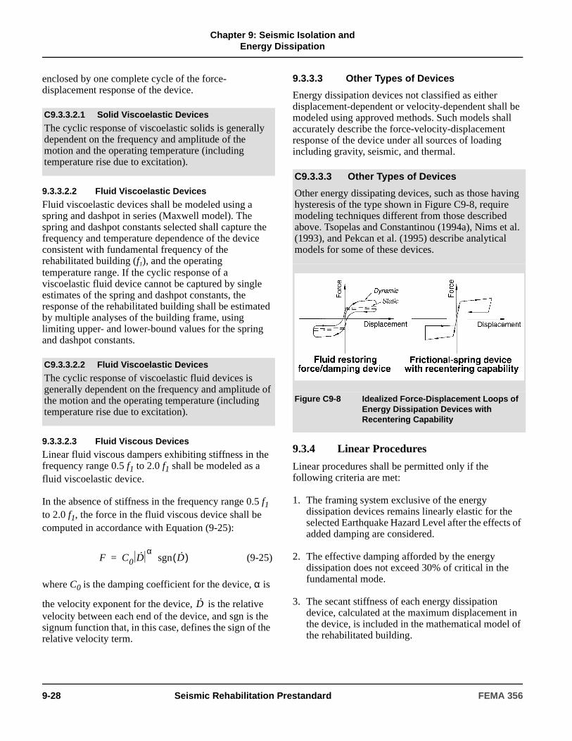
Chapter 9: Seismic Isolation and
Energy Dissipation
enclosed by one complete cycle of the force-displacement response of the device.
9.3.3.2.2 Fluid Viscoelastic Devices
Fluid viscoelastic devices shall be modeled using a spring and dashpot in series (Maxwell model). The spring and dashpot constants selected shall capture the frequency and temperature dependence of the device consistent with fundamental frequency of the rehabilitated building (f1), and the operating temperature range. If the cyclic response of a viscoelastic fluid device cannot be captured by single estimates of the spring and dashpot constants, the response of the rehabilitated building shall be estimated by multiple analyses of the building frame, using limiting upper- and lower-bound values for the spring and dashpot constants.
9.3.3.2.3 Fluid Viscous Devices
Linear fluid viscous dampers exhibiting stiffness in the frequency range 0.5 f1 to 2.0 f1 shall be modeled as a fluid viscoelastic device.
In the absence of stiffness in the frequency range 0.5 f1 to 2.0 f1, the force in the fluid viscous device shall be computed in accordance with Equation (9-25):
(9-25)
where C0 is the damping coefficient for the device, α is
the velocity exponent for the device, is the relative velocity between each end of the device, and sgn is the signum function that, in this case, defines the sign of the relative velocity term.
9.3.3.3 Other Types of Devices
Energy dissipation devices not classified as either displacement-dependent or velocity-dependent shall be modeled using approved methods. Such models shall accurately describe the force-velocity-displacement response of the device under all sources of loading including gravity, seismic, and thermal.
9.3.4 Linear Procedures
Linear procedures shall be permitted only if the following criteria are met:
1. The framing system exclusive of the energy dissipation devices remains linearly elastic for the selected Earthquake Hazard Level after the effects of added damping are considered.
2. The effective damping afforded by the energy dissipation does not exceed 30% of critical in the fundamental mode.
3. The secant stiffness of each energy dissipation device, calculated at the maximum displacement in the device, is included in the mathematical model of the rehabilitated building.
C9.3.3.2.1 Solid Viscoelastic Devices
The cyclic response of viscoelastic solids is generally dependent on the frequency and amplitude of the motion and the operating temperature (including temperature rise due to excitation).
C9.3.3.2.2 Fluid Viscoelastic Devices
The cyclic response of viscoelastic fluid devices is generally dependent on the frequency and amplitude of the motion and the operating temperature (including temperature rise due to excitation).
F C0 D·α
sgn D·( )=
D·
C9.3.3.3 Other Types of Devices
Other energy dissipating devices, such as those having hysteresis of the type shown in Figure C9-8, require modeling techniques different from those described above. Tsopelas and Constantinou (1994a), Nims et al. (1993), and Pekcan et al. (1995) describe analytical models for some of these devices.
Figure C9-8 Idealized Force-Displacement Loops of Energy Dissipation Devices with Recentering Capability
9-28 Seismic Rehabilitation Prestandard FEMA 356
Chapter 9: Seismic Isolation and
Energy Dissipation
4. When evaluating the regularity of a building, the energy dissipation devices are included in the mathematical model.
9.3.4.1 Linear Static Procedure
9.3.4.1.1 Displacement-Dependent Devices
Use of The Linear Static Procedure (LSP) shall be permitted to analyze displacement-dependent energy dissipation devices, provided that in addition to the requirements of Section 9.3.4, the following requirements are satisfied:
1. The ratio of the maximum resistance in each story, in the direction under consideration, to the story shear demand calculated using Equations (3-11) and (3-12), shall range between 80% and 120% of the average value of the ratio for all stories. The maximum story resistance shall include the contributions from all components, elements, and energy dissipation devices.
2. The maximum resistance of all energy dissipation devices in a story, in the direction under consideration, shall not exceed 50% of the resistance of the remainder of the framing where said resistance is calculated at the displacements anticipated in the BSE-2. Aging and environmental effects shall be considered in calculating the maximum resistance of the energy dissipation devices.
The pseudolateral load of Equation (3-10) shall be reduced by the damping modification factors of Table 1-6 to account for the energy dissipation (damping) afforded by the energy dissipation devices. The damping effect shall be calculated in accordance with Equation (9-26):
(9-26)
where β is the damping in the framing system and shall be set equal to 0.05 unless modified in Section 1.6.1.4, Wj shall be taken as the work done by device j in one complete cycle corresponding to floor displacements δi, the summation extends over all devices j, and Wk is the maximum strain energy in the frame, determined using Equation (9-27):
(9-27)
where Fi shall be taken as the inertia force at floor level i and the summation extends over all floor levels.
9.3.4.1.2 Velocity-Dependent Devices
Use of the LSP shall be permitted to analyze velocity-dependent energy dissipation devices, provided that in addition to the requirements of Section 9.3.4, the following requirements are satisfied:
1. The maximum resistance of all energy dissipation devices in a story in the direction under consideration shall not exceed 50% of the resistance of the remainder of the framing where said resistance is calculated at the displacements anticipated in the BSE-2. Aging and environmental effects shall be considered in calculating the maximum resistance of the energy dissipation devices.
2. The pseudolateral load of Equation (3-10) shall be reduced by the damping modification factors of Table 1-6 to account for the energy dissipation (damping) afforded by the energy dissipation devices. The damping effect shall be calculated in accordance with Equation (9-28):
(9-28)
where β is the damping in the structural frame and shall be set equal to 0.05 unless modified in Section 1.6.1.5.3, Wj shall be taken as the work done by device j in one complete cycle corresponding to floor displacements δi, the summation extends over all devices j, and Wk is the maximum strain energy in the frame, determined using Equation (9-27).
The work done by linear viscous device j in one complete cycle of loading shall be calculated in accordance with Equation (9-29):
(9-29)
βeff β
Wjj
∑4πWk--------------+=
Wk12--- Fiδi
i∑=
βeff β
Wjj
∑4πWk--------------+=
Wj2π2
T---------Cjδrj
2=
FEMA 356 Seismic Rehabilitation Prestandard 9-29

Chapter 9: Seismic Isolation and
Energy Dissipation
where T is the fundamental period of the rehabilitated building including the stiffness of the velocity-dependent devices, Cj is the damping constant for device j, and δrj is the relative displacement between the ends of device j along the axis of device j.
Calculation of effective damping in accordance with Equation (9-30) rather than Equation (9-28) shall be permitted for linear viscous devices:
(9-30)
where is the angle of inclination of device j to the
horizontal, is the first mode relative displacement
between the ends of device j in the horizontal direction, wi is the reactive weight of floor level i, is the first
mode displacement at floor level i, and other terms are as defined above.
9.3.4.1.3 Design Actions
The design actions for components of the rehabilitated building shall be calculated in three distinct stages of deformation as follows. The maximum action shall be used for design.
1. At the stage of maximum drift. The lateral forces at each level of the building shall be calculated using Equation (3-11), where V is the modified equivalent base shear.
2. At the stage of maximum velocity and zero drift. The viscous component of force in each energy dissipation device shall be calculated by Equations
(9-22) or (9-25), where the relative velocity is given by 2π f1 D, where D is the relative displacement between the ends of the device calculated at the stage of maximum drift. The calculated viscous forces shall be applied to the mathematical model of the building at the points of attachment of the devices and in directions consistent with the deformed shape of the building at maximum drift. The horizontal inertia forces at each floor level of the building shall be applied
concurrently with the viscous forces so that the horizontal displacement of each floor level is zero.
3. At the stage of maximum floor acceleration. Design actions in components of the rehabilitated building shall be determined as the sum of actions determined at the stage of maximum drift times CF1, and actions determined at the stage of maximum velocity times CF2, where
(9-31)
(9-32)
in which βeff is defined by either Equation (9-28) or Equation (9-30).
9.3.4.2 Linear Dynamic Procedure
If the Linear Dynamic Procedure (LDP) is selected based on the requirements of Section 9.2.3.3 and Section 2.4, the LDP of Section 3.3.2.2 shall be followed unless explicitly modified by this section.
Use of the response spectrum method of the LDP shall be permitted when the effective damping in the fundamental mode of the rehabilitated building, in each principal direction, does not exceed 30% of critical.
9.3.4.2.1 Displacement-Dependent Devices
Application of the LDP for the analysis of rehabilitated buildings incorporating displacement-dependent devices shall comply with the restrictions set forth in Section 9.3.4.1.1.
For analysis by the Response Spectrum Method, modification of the 5%-damped response spectrum shall be permitted to account for the damping afforded by the displacement-dependent energy dissipation devices. The 5%-damped acceleration spectrum shall be reduced by the modal-dependent damping modification factor, B, either Bs or B1, for periods in the vicinity of the mode under consideration; the value of B will be different for each mode of vibration. The damping modification factor in each significant mode shall be determined using Table 1-6 and the calculated effective damping in that mode. The effective damping shall be determined using a procedure similar to that described in Section 9.3.4.1.1.
βeff β
T Cj cos2θj φrj
2
j∑
4πwi
g-----
φi2
i∑
------------------------------------------+=
θj
φrj
φi
D·
CF1 tan1–
2βeff( )[ ]cos=
CF2 tan1–
2βeff( )[ ]sin=
9-30 Seismic Rehabilitation Prestandard FEMA 356

Chapter 9: Seismic Isolation and
Energy Dissipation
If the maximum base shear force calculated by dynamic analysis is less than 80% of the modified equivalent base shear of Section 9.3.4.1, component and element actions and deformations shall be proportionally increased to correspond to 80% of the modified equivalent base shear.
9.3.4.2.2 Velocity-Dependent Devices
For analysis by the Response Spectrum Method, modification of the 5%-damped response spectrum shall be permitted to account for the damping afforded by the velocity-dependent energy dissipation devices. The 5%-damped acceleration spectrum shall be reduced by the modal-dependent damping modification factor, B, either Bs or B1, for periods in the vicinity of the mode under consideration; note that the value of B will be different for each mode of vibration. The damping modification factor in each significant mode shall be determined using Table 1-6 and the calculated effective damping in that mode.
The effective damping in the m-th mode of vibration shall be calculated in accordance with
Equation (9-33):
(9-33)
where βm is the m-th mode damping in the building frame, Wmj is work done by device j in one complete cycle corresponding to modal floor displacements δmi, and Wmk is the maximum strain energy in the frame in the m-th mode, determined using Equation (9-34):
(9-34)
where Fmi is the m-th mode horizontal inertia force at floor level i and δmi is the m-th mode horizontal displacement at floor level i. The work done by linear viscous device j in one complete cycle of loading in the m-th mode may be calculated in accordance with Equation (9-35):
(9-35)
where Tm is the m-th mode period of the rehabilitated building including the stiffness of the velocity-dependent devices, Cj is the damping constant for device j, and δmrj is the m-th mode relative displacement between the ends of device j along the axis of device j.
In addition to direct application of the Response Spectrum Method in accordance with this section to obtain member actions at maximum drift, member actions at maximum velocity and maximum acceleration in each significant mode shall be determined using the procedure described in Sections 9.3.4.1.2. The combination factors CF1 and CF2 shall be determined based on Equations (9-31) and (9-32) using βeff –m for the m-th mode.
If the maximum base shear force calculated by dynamic analysis is less than 80% of the modified equivalent base shear of Section 9.3.4.1, component and element actions and deformations shall be proportionally increased to correspond to 80% of the modified equivalent base shear.
9.3.5 Nonlinear Procedures
9.3.5.1 Nonlinear Static Procedure
If the Nonlinear Static Procedure (NSP) is selected based on the requirements of Section 9.2.3.3 and Section 2.4, the NSP of Section 3.3.3 shall be followed unless explicitly modified by this section.
The nonlinear mathematical model of the rehabilitated building shall include the nonlinear force-velocity-displacement characteristics of the energy dissipation devices explicitly, and the mechanical characteristics of the components supporting the devices. Stiffness characteristics shall be consistent with the deformations corresponding to the target displacement and a frequency equal to the inverse of period Te, as defined in Section 3.3.3.2.
The nonlinear mathematical model of the rehabilitated building shall include the nonlinear force-velocity-displacement characteristics of the energy dissipation devices, and the mechanical characteristics of the components supporting the devices. Energy dissipation devices with stiffness and damping characteristics that are dependent on excitation frequency and/or temperature shall be modeled with characteristics consistent with (1) the deformations expected at the
βeff m–( )
βeff m– βm
Wmjj
∑4πWmk------------------+=
Wmk12--- Fmiδmi
i∑=
Wmj2π2
Tm---------Cjδmrj
2=
FEMA 356 Seismic Rehabilitation Prestandard 9-31
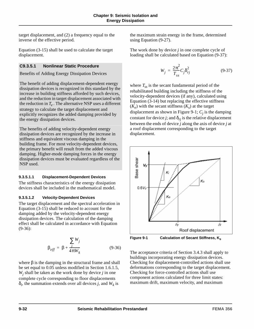
Chapter 9: Seismic Isolation and
Energy Dissipation
target displacement, and (2) a frequency equal to the inverse of the effective period.
Equation (3-15) shall be used to calculate the target displacement.
9.3.5.1.1 Displacement-Dependent Devices
The stiffness characteristics of the energy dissipation devices shall be included in the mathematical model.
9.3.5.1.2 Velocity-Dependent Devices
The target displacement and the spectral acceleration in Equation (3-15) shall be reduced to account for the damping added by the velocity-dependent energy dissipation devices. The calculation of the damping effect shall be calculated in accordance with Equation (9-36):
(9-36)
where β is the damping in the structural frame and shall be set equal to 0.05 unless modified in Section 1.6.1.5, Wj shall be taken as the work done by device j in one complete cycle corresponding to floor displacements δi, the summation extends over all devices j, and Wk is
the maximum strain energy in the frame, determined using Equation (9-27).
The work done by device j in one complete cycle of loading shall be calculated based on Equation (9-37):
(9-37)
where Tss is the secant fundamental period of the rehabilitated building including the stiffness of the velocity-dependent devices (if any), calculated using Equation (3-14) but replacing the effective stiffness (Ke) with the secant stiffness (Ks) at the target displacement as shown in Figure 9-1; Cj is the damping constant for device j; and δrj is the relative displacement between the ends of device j along the axis of device j at a roof displacement corresponding to the target displacement.
The acceptance criteria of Section 3.4.3 shall apply to buildings incorporating energy dissipation devices. Checking for displacement-controlled actions shall use deformations corresponding to the target displacement. Checking for force-controlled actions shall use component actions calculated for three limit states: maximum drift, maximum velocity, and maximum
C9.3.5.1 Nonlinear Static Procedure
Benefits of Adding Energy Dissipation Devices
The benefit of adding displacement-dependent energy dissipation devices is recognized in this standard by the increase in building stiffness afforded by such devices, and the reduction in target displacement associated with the reduction in Te . The alternative NSP uses a different strategy to calculate the target displacement and explicitly recognizes the added damping provided by the energy dissipation devices.
The benefits of adding velocity-dependent energy dissipation devices are recognized by the increase in stiffness and equivalent viscous damping in the building frame. For most velocity-dependent devices, the primary benefit will result from the added viscous damping. Higher-mode damping forces in the energy dissipation devices must be evaluated regardless of the NSP used.
βeff β
Wjj
∑4πWk--------------+=
Figure 9-1 Calculation of Secant Stiffness, Ks
Wj2π2
Tss---------Cjδrj
2=
9-32 Seismic Rehabilitation Prestandard FEMA 356

Chapter 9: Seismic Isolation and
Energy Dissipation
acceleration. Maximum actions shall be used for design. Higher-mode effects shall be explicitly evaluated.
9.3.5.2 Nonlinear Dynamic Procedure
If the Nonlinear Dynamic Procedure (NDP) is selected based on the requirements of Section 9.2.3.3 and Section 2.4, a nonlinear time history analysis shall be performed as required by Section 3.3.4.2, except as modified by this section. The mathematical model shall account for both the plan and vertical spatial distribution of the energy dissipation devices in the rehabilitated building. If the energy dissipation devices are dependent on excitation frequency, operating temperature (including temperature rise due to excitation), deformation (or strain), velocity, sustained loads, and bilateral loads, such dependence shall be accounted for in the analysis by assuming upper- and lower-bound properties to bound the solution.
The viscous forces in velocity-dependent energy dissipation devices shall be included in the calculation of design actions and deformations. Substitution of viscous effects in energy dissipation devices by global structural damping for nonlinear time-history analysis shall not be permitted.
9.3.6 Detailed Systems Requirements
9.3.6.1 General
The energy dissipation system and the remainder of the lateral-force-resisting system shall comply with the detailed systems requirements specified in this section.
9.3.6.2 Operating Temperature
The analysis of a rehabilitated building shall account for variations in the force-displacement response of the energy dissipation devices due to variation in the ambient temperature and temperature rise due to earthquake cyclic excitation. Multiple analysis shall be performed to bound the seismic response of the building during the Design Earthquake, and develop limits for defining the acceptable response of the prototype devices and production devices.
9.3.6.3 Environmental Conditions
In addition to the requirements for vertical and lateral loads induced by wind and earthquake actions, the energy dissipation devices shall be designed with consideration given to other environmental conditions, including aging effects, creep, fatigue, ambient temperature, and exposure to moisture and damaging substances.
C9.3.5.1.2 Velocity-Dependent Devices
The use of Equation (9-36) will generally capture the maximum displacement of the building.
C9.3.5.2 Nonlinear Dynamic Procedure
If energy dissipation devices are dependent on loading frequency, operating temperature (including temperature rise due to excitation), deformation (or strain), velocity, sustained loads, and bilateral loads, such dependence should be accounted for in the nonlinear time history analysis. One way to account for variations in the force-deformation response of energy dissipation devices is to perform multiple analyses of the rehabilitated building using the likely bounding response characteristics of the energy dissipation devices. The design of the rehabilitated building, including the energy dissipation devices, should be based on the maximum responses computed from the multiple analyses.
The viscous forces (if any) developed in the seismic framing system should be accounted for in the analysis and design of the seismic framing system. Evaluation of member action histories should be based on nodal displacements (operating on member stiffness matrices) and nodal velocities (operating on member damping matrices).
Key to the acceptable response of a rehabilitated building incorporating energy dissipation devices is the stable response of the energy dissipation devices. The forces and deformations in the energy dissipation devices that develop during the Design Earthquake should be demonstrated to be adequate by prototype testing in accordance with Section 9.3.8.
C9.3.6.2 Operating Temperature
The force-displacement response of an energy dissipation device will generally be dependent on ambient temperature and temperature rise due to cyclic or earthquake excitation.
FEMA 356 Seismic Rehabilitation Prestandard 9-33
Chapter 9: Seismic Isolation and
Energy Dissipation
9.3.6.4 Wind Forces
The fatigue life of energy dissipation devices, or components thereof, including seals in a fluid viscous device, shall be investigated and shown to be adequate for the design life of the devices. Devices subject to failure by low-cycle fatigue shall resist wind forces in the linearly elastic range.
9.3.6.5 Inspection and Replacement
Access for inspection and replacement of the energy dissipation devices shall be provided.
9.3.6.6 Manufacturing Quality Control
A manufacturing quality control plan for production of energy dissipation devices shall be established by the engineer of record. This plan shall include descriptions of the manufacturing processes, inspection procedures, and testing necessary to ensure quality control of production devices.
9.3.6.7 Maintenance
The engineer of record shall establish a maintenance and testing schedule for energy dissipation devices to ensure reliable response of the devices over the design life of the devices. The degree of maintenance and testing shall reflect the established in-service history of the devices.
9.3.7 Design Review
9.3.7.1 General
Design review of all rehabilitated buildings incorporating energy dissipation devices shall be performed in accordance with the requirements of Section 2.7, unless modified by the requirements of this section. Design review of the energy dissipation system and related test programs shall be performed by an independent engineering review panel that includes persons experienced in seismic analysis and the theory and application of energy dissipation methods.
The following items shall be included in the design review:
1. Preliminary design including sizing of the devices.
2. Prototype testing conducted in accordance with Section 9.3.8.2.
3. Final design of the rehabilitated building and supporting analyses.
4. Manufacturing quality control program for the energy dissipation devices.
9.3.8 Required Tests of Energy Dissipation Devices
9.3.8.1 General
The force-displacement relations and damping values assumed in the design of the energy dissipation system shall be confirmed by the tests conducted in accordance with this section prior to production of devices for construction. If tests conducted in accordance with this section precede the design phase of a project, the results of the testing program shall be used for the design.
The tests specified in this section shall be conducted to: (1) confirm the force-displacement properties of the energy dissipation devices assumed for design, and (2) demonstrate the robustness of individual devices to extreme seismic excitation. These tests shall not be considered as satisfying the manufacturing quality control (production) plan of Section 9.3.6.6.
The engineer of record shall provide explicit acceptance criteria for the effective stiffness and damping values established by the prototype tests. These criteria shall reflect the values assumed in design, account for likely variations in material properties, and provide limiting response values outside of which devices will be rejected.
The engineer of record shall provide explicit acceptance criteria for the effective stiffness and damping values established by the production tests of Section 9.3.6.6. The results of the prototype tests shall form the basis of the acceptance criteria for the production tests unless an alternate basis is established by the engineer of record in the specification. Such acceptance criteria shall recognize the influence of loading history on the response of individual devices by requiring production testing of devices prior to prototype testing.
The fabrication and quality control procedures used for all prototype and production devices shall be identical. These procedures shall be approved by the engineer of record prior to the fabrication of prototype devices.
9-34 Seismic Rehabilitation Prestandard FEMA 356

Chapter 9: Seismic Isolation and
Energy Dissipation
9.3.8.2 Prototype Tests
9.3.8.2.1 General
The following prototype tests shall be performed separately on two full-size devices of each type and size used in the design. If approved by the engineer of record, selection of representative sizes of each type of device shall be permitted for prototype testing, rather than each type and size, provided that the fabrication and quality control procedures are identical for each type and size of devices used in the rehabilitated building.
Test specimens shall not be used for construction unless approved in writing by the engineer of record.
9.3.8.2.2 Data Recording
The force-deflection relationship for each cycle of each test shall be recorded electronically.
9.3.8.2.3 Sequence and Cycles of Testing
For the following minimum test sequence, each energy dissipation device shall be loaded to simulate the gravity loads on the device as installed in the building and the extreme ambient temperatures anticipated.
1. Each device shall be loaded with the number of cycles expected in the design wind storm, but not less than 2000 fully-reversed cycles of load (displacement-dependent and viscoelastic devices) or displacement (viscous devices) at amplitudes expected in the design wind storm, at a frequency equal to the inverse of the fundamental period of the rehabilitated building.
EXCEPTION: Devices not subject to wind-induced forces or displacements need not be subjected to these tests.
2. Each device shall be loaded with 20 fully reversed cycles at the displacement in the energy dissipation device corresponding to the BSE-2, at a frequency equal to the inverse of the fundamental period of the rehabilitated building.
EXCEPTION: Testing methods for energy dissipation devices other than those noted above shall be permitted, provided that: (1) equivalency between the proposed method and cyclic testing can be demonstrated; (2) the proposed method captures the dependence of the energy dissipation device response to ambient temperature, frequency of
loading, and temperature rise during testing; and (3) the proposed method is approved by the engineer of record.
9.3.8.2.4 Devices Dependent on Velocity and/or Frequency of Excitation
If the force-deformation properties of the energy dissipation devices at any displacement less than or equal to the total design displacement change by more than 15% for changes in testing frequency from 0.5 f1 to 2.0 f1, the preceding tests shall be performed at frequencies equal to 0.5 f1, f1, and 2.0 f1.
EXCEPTION: If reduced-scale prototypes are used to quantify the rate-dependent properties of energy dissipation devices, the reduced-scale prototypes shall be of the same type and materials—and manufactured with the same processes and quality control procedures—as full-scale prototypes, and tested at a similitude-scaled frequency that represents the full-scale loading rates.
9.3.8.2.5 Devices Dependent on Bilateral Displacement
If the energy dissipation devices are subjected to bilateral deformation, the preceding tests shall be made at both zero bilateral displacement, and peak lateral displacement in the BSE-2.
EXCEPTION: If reduced-scale prototypes are used to quantify the bilateral displacement properties of the energy dissipation devices, the reduced-scale prototypes shall be of the same type and materials, and manufactured with the same processes and quality control procedures as full-scale prototypes, and tested at similitude-scaled displacements that represent the full-scale displacements.
9.3.8.2.6 Testing Similar Devices
Energy dissipation devices that are (1) of similar size, identical materials, internal construction, and static and dynamic internal pressures (if any), and (2) fabricated with identical internal processes and manufacturing quality control procedures, and that have been previously tested by an independent laboratory in the
C9.3.8.2.3 Sequence and Cycles of Testing
Energy dissipation devices should not form part of the gravity-load-resisting system, but may be required to support some gravity load.
FEMA 356 Seismic Rehabilitation Prestandard 9-35

Chapter 9: Seismic Isolation and
Energy Dissipation
manner described above need not be tested, provided that:
1. All pertinent testing data are made available to, and are approved by, the engineer of record.
2. The manufacturer can substantiate the similarity of the previously tested devices to the satisfaction of the engineer of record.
3. The submission of data from a previous testing program is approved in writing by the engineer of record.
9.3.8.3 Determination of Force-Displacement Characteristics
The force-displacement characteristics of an energy dissipation device shall be based on the cyclic load and displacement tests of prototype devices specified in Section 9.3.8.2.
As required, the effective stiffness (keff) of an energy dissipation device with stiffness shall be calculated for each cycle of deformation in accordance with Equation (9-38):
(9-38)
where forces F+ and F– shall be calculated at displacements ∆+ and ∆–, respectively. The effective stiffness of an energy dissipation device shall be established at the test displacements given in Section 9.3.8.2.3.
The equivalent viscous damping of an energy dissipation device (βeff) exhibiting stiffness shall be calculated for each cycle of deformation based on Equation (9-39):
(9-39)
where keff shall be calculated in accordance with Equation (9-38), and WD shall be taken as the area enclosed by one complete cycle of the force-displacement response for a single energy dissipation
device at a prototype test displacement (∆ave) equal to
the average of the absolute values of displacements ∆+
and ∆–.
9.3.8.4 System Adequacy
The performance of a prototype device shall be considered adequate if all of the following conditions are satisfied:
1. The force-displacement curves for the tests in Section 9.3.8.2.3 have nonnegative incremental force-carrying capacities.
EXCEPTION: Energy dissipation devices that exhibit velocity-dependent behavior need not comply with this requirement.
2. Within each test of Section 9.3.8.2.3, the effective stiffness (keff) of a prototype energy dissipation device for any one cycle does not differ by more than plus or minus 15% from the average effective stiffness as calculated from all cycles in that test.
EXCEPTIONS: (1) The 15% limit may be increased by the engineer of record in the specification, provided that the increased limit has been demonstrated by analysis to not have a deleterious effect on the response of the rehabilitated building. (2) Fluid viscous energy dissipation devices, and other devices that do not have effective stiffness, need not comply with this requirement.
3. Within each test of Section 9.3.8.2.3, the maximum force and minimum force at zero displacement for a prototype device for any one cycle does not differ by more than plus or minus 15% from the average maximum and minimum forces as calculated from all cycles in that test.
EXCEPTION: The 15% limit may be increased by the engineer of record in the specification, provided that the increased limit has been demonstrated by analysis to not have a deleterious effect on the response of the rehabilitated building.
4. Within each test of Section 9.3.8.2.3, the area of the hysteresis loop (WD) of a prototype energy dissipation device for any one cycle does not differ by more than plus or minus 15% from the average
keffF
–F
++
∆– ∆++
-------------------------=
βeff1
2π------
WD
keff∆ave2
--------------------=
9-36 Seismic Rehabilitation Prestandard FEMA 356
Chapter 9: Seismic Isolation and
Energy Dissipation
area of the hysteresis curve as calculated from all cycles in that test.
EXCEPTION: The 15% limit may be increased by the engineer of record in the specification, provided that the increased limit has been demonstrated by analysis to not have a deleterious effect on the response of the rehabilitated building.
5. For displacement-dependent devices, the average effective stiffness, average maximum and minimum force at zero displacement, and average area of the hysteresis loop (WD), calculated for each test in the sequence described in Section 9.3.8.2.3, shall fall within the limits set by the engineer of record in the specification. The area of the hysteresis loop at the end of cyclic testing shall not differ by more than plus or minus 15% from the average area of the 20 test cycles.
6. For velocity-dependent devices, the average maximum and minimum force at zero displacement, effective stiffness (for viscoelastic devices only), and average area of the hysteresis loop (WD), calculated for each test in the sequence described in Section 9.3.8.2.3, shall fall within the limits set by the engineer of record in the specification.
9.4 Other Response Control SystemsThe analysis and design of other response control systems shall be reviewed by an independent engineering review panel in accordance with the requirements of Section 9.3.7. This review panel shall be selected by the owner prior to the development of the preliminary design.
C9.4 Other Response Control SystemsResponse control strategies other than base isolation (Section 9.2) and passive energy dissipation (Section 9.3) systems have been proposed. Dynamic vibration absorption and active control systems are two such response control strategies. Although both dynamic vibration absorption and active control systems have been implemented to control the wind- induced vibration of buildings, the technology is not sufficiently mature and the necessary hardware is not sufficiently robust to warrant the preparation of general guidelines for the implementation of other response control systems.
FEMA 356 Seismic Rehabilitation Prestandard 9-37

Chapter 9: Seismic Isolation and
Energy Dissipation
9-38 Seismic Rehabilitation Prestandard FEMA 356
10. Simplified Rehabilitation
10.1 ScopeThis chapter sets forth requirements for the rehabilitation of buildings using the Simplified Rehabilitation Method. Section 10.2 outlines the procedure of the Simplified Rehabilitation Method. Section 10.3 specifies actions for correction of deficiencies using the Simplified Rehabilitation Method.
10.2 ProcedureUse of Simplified Rehabilitation shall be permitted in accordance with the limitations of Section 2.3.1. The Simplified Rehabilitation Method shall be implemented by completing each of the following steps:
1. The building shall be classified as one of the Model Building Types listed in Table 10-1 and defined in Table 10-2.
2. A Tier 1 and a Tier 2 Seismic Evaluation of the building in its existing state shall be performed for
C10.1 ScopeThe Simplified Rehabilitation Method is intended primarily for use on a select group of simple buildings.
The Simplified Rehabilitation Method only applies to buildings that fit into one of the Model Building Types and conform to the limitations of Table 10-1, which sets the standard for simple, regularly configured buildings defined in Table 10-2. Building regularity is an important consideration in the application of the method. Regularity is determined by checklist statements addressing building configuration issues. The Simplified Rehabilitation Method may be used if an evaluation shows no deficiencies with regard to regularity. Buildings that have configuration irregularities (as determined by an FEMA 310 Tier 1 or Tier 2 Evaluation) may use this Simplified Rehabilitation Method to achieve the Life Safety Building Performance Level only if the resulting rehabilitation work eliminates all significant vertical and horizontal irregularities and results in a building with a complete seismic lateral-force-resisting load path.
The technique described in this chapter is one of the two rehabilitation methods defined in Section 2.3. It is to be used only by a design professional, and only in a manner consistent with this standard. Consideration must be given to all aspects of the rehabilitation process, including the development of appropriate as-built information, proper design of rehabilitation techniques, and specification of appropriate levels of quality assurance.
“Simplified Rehabilitation” reflects a level of analysis and design that (1) is appropriate for small, regular buildings and buildings that do not require advanced analytical procedures; and (2) achieves the Life Safety Performance Level for the BSE-1 Earthquake Hazard Level as defined in Chapter 1, but does not necessarily achieve the Basic Safety Objective (BSO).
FEMA 178, the NEHRP Handbook for the Seismic Evaluation of Existing Buildings, a nationally applicable method for seismic evaluation of buildings, was the basis for the Simplified Rehabilitation Method in FEMA 273. FEMA 178 is based on the historic behavior of buildings in past earthquakes and the success of current code provisions in achieving the Life Safety Building Performance Level. It is organized around a set of common construction styles called model buildings.
Since the preliminary version of FEMA 178 was completed in the late 1980s, new information has become available and has been incorporated into FEMA 310, which is an updated version of FEMA 178. This information includes additional Model Building Types, eight new evaluation statements for potential deficiencies, a reorganization of the procedure to clearly state the intended three-tier approach, and new analysis techniques that parallel those of FEMA 273. FEMA 310 is the basis of the Simplified Rehabilitation Method in this standard.
The Simplified Rehabilitation Method may yield a more conservative result than the Systematic Method because of a variety of simplifying assumptions.
FEMA 356 Seismic Rehabilitation Prestandard 10-1

Chapter 10: Simplified Rehabilitation
the Life Safety Building Performance Level in accordance with FEMA 310. In the event of differences between this standard and the FEMA 310 procedures, the FEMA 310 procedures shall govern.
3. The deficiencies identified by the FEMA 310 Evaluation conducted in Step 2 shall be ranked from highest to lowest priority.
4. Rehabilitation measures shall be developed in accordance with Section 10.3 to mitigate the deficiencies identified by the FEMA 310 Evaluation.
5. The proposed rehabilitation scheme shall be designed such that all deficiencies identified by the FEMA 310 Evaluation of Step 2 are eliminated.
6. A complete Tier 1 and Tier 2 Evaluation of the building in its proposed rehabilitated state shall be performed in accordance with FEMA 310. In the event of differences between this standard and the FEMA 310 procedures, the FEMA 310 procedures shall govern.
7. Rehabilitation measures for architectural, mechanical, and electrical components shall be developed in accordance with Chapter 11 for the Life Safety Nonstructural Performance Level at the BSE-1 Earthquake Hazard Level.
8. Construction documents, including drawings and specifications and a quality assurance program, shall be developed as defined in Chapter 2.
C10.2 ProcedureThe basis of the Simplified Rehabilitation Method is the FEMA 310 procedure. There are intentional differences between the provisions of this standard and FEMA 310 with regard to site class amplification factors, seismicity, and design earthquake, among other issues.
For simple buildings with specific deficiencies, it is possible and advisable to prioritize the rehabilitation measures. This is often done when the construction has limited funding or must take place while the building is occupied. In both cases, it is preferable to correct the worst deficiency first.
Potential deficiencies are ranked in Tables C10-1 through C10-19; items in these tables are ordered roughly from highest priority at the top to lowest at the bottom, although this can vary widely in individual cases.
FEMA 310 lists specific deficiencies both by Model Building Type and by association with each building system. Tables C10-1 through C10-19 of this standard further group deficiencies by general characteristics. For example, the deficiency listing “Diaphragm Stiffness/Strength,” includes deficiencies related to the type of sheathing used, diaphragm span, and lack of blocking. Table C10-20 provides a complete cross-reference for sections in this standard, in FEMA 310, and in FEMA 178.
Within the table for each Model Building Type, each deficiency group is ranked from most critical at the top to least critical at the bottom. For example, in Table C10-12, in a precast/tilt-up concrete shear wall with flexible diaphragm (PC1) building, the lack of positive gravity frame connections (e.g., of girders to posts by sheet metal hardware or bolts) has a greater potential to lower the building’s performance (a partial collapse of the roof structure supported by the beam), than a deficiency in lateral forces on foundations (e.g., poor reinforcing in the footings).
The ranking was based on the following characteristics of each deficiency group:
1. Most critical
1.1. Building systems: those with a discontinuous load path and little redundancy.
1.2. Building elements: those with low strength and low ductility.
2. Intermediate
2.1. Building systems: those with a discontinuous load path but substantial redundancy.
2.2. Building elements: those with substantial strength but low ductility.
10-2 Seismic Rehabilitation Prestandard FEMA 356

Chapter 10: Simplified Rehabilitation
3. Least critical
a. Building systems: those with a substantial load path but little redundancy.
b. Building elements: those with low strength but substantial ductility.
The intent of Tables C10-1 to C10-19 is to guide the design professional in accomplishing a Partial Rehabilitation Objective. For example, if the foundation is strengthened in a PC1 building but a poor girder/wall connection is left alone, relatively little has been done to improve the expected performance of the building. Considerable professional judgment must be used when evaluating a structure’s unique behavior and determining which deficiencies should be strengthened and in what order.
As a rule, the resulting rehabilitated building must be one of the Model Building Types. For example, adding concrete shear walls to concrete shear wall buildings or adding a complete system of concrete shear walls to a concrete frame building meets this requirement. Steel bracing may be used to strengthen wood or URM construction. For large buildings, it is advisable to explore several rehabilitation strategies and compare alternative ways of eliminating deficiencies.
For a Limited Rehabilitation Objective, the deficiencies identified by the FEMA 310 Evaluation of Step 2 should be mitigated in order of priority based on the ranking performed in Step 3.
A complete evaluation of the building should confirm that the strengthening of any one element or system has not merely shifted the deficiency to another.
Specific application of the Systematic Rehabilitation Method is needed to achieve the BSO. The total strength of the building should be sufficient, and the ability of the building to experience the predicted maximum displacement without partial or complete collapse must be established.
If only a Partial Rehabilitation or Limited Rehabilitation Objective is intended, deficiencies should be corrected in priority order and in a way that will facilitate fulfillment of the requirements of a higher objective at a later date. Care must be taken to ensure that a Partial Rehabilitation effort does not make the building’s overall performance worse by unintentionally channeling failure to a more critical element.
FEMA 356 Seismic Rehabilitation Prestandard 10-3

Chapter 10: Simplified Rehabilitation
Table 10-1 Limitations on Use of the Simplified Rehabilitation Method
Model Building Type2
Maximum Building Height in Stories by Seismic Zone1 for Use of the Simplified
Rehabilitation Method
Low Moderate High
Wood Frame
Light (W1) 3 3 2
Multistory Multi-Unit Residential (W1A) 3 3 2
Commercial and Industrial (W2) 3 3 2
Steel Moment Frame
Stiff Diaphragm (S1) 6 4 3
Flexible Diaphragm (S1A) 4 4 3
Steel Braced Frame
Stiff Diaphragm (S2) 6 4 3
Flexible Diaphragm (S2A) 3 3 3
Steel Light Frame (S3) 2 2 2
Steel Frame with Concrete Shear Walls (S4) 6 4 3
Steel Frame with Infill Masonry Shear Walls
Stiff Diaphragm (S5) 3 3 n.p.
Flexible Diaphragm (S5A) 3 3 n.p.
Concrete Moment Frame (C1) 3 n.p. n.p.
Concrete Shear Walls
Stiff Diaphragm (C2) 6 4 3
Flexible Diaphragm (C2A) 3 3 3
Concrete Frame with Infill Masonry Shear Walls
Stiff Diaphragm (C3) 3 n.p. n.p.
Flexible Diaphragm (C3A) 3 n.p. n.p.
Precast/Tilt-up Concrete Shear Walls
Flexible Diaphragm (PC1) 3 2 2
Stiff Diaphragm (PC1A) 3 2 2
Precast Concrete Frame
With Shear Walls (PC2) 3 2 n.p.
Without Shear Walls (PC2A) n.p. n.p. n.p.
Reinforced Masonry Bearing Walls
Flexible Diaphragm (RM1) 3 3 3
Stiff Diaphragm (RM2) 6 4 3
= Use of Simplified Rehabilitation Method shall not be permitted.
1. Seismic Zones shall be as defined in Section 1.6.3.
2. Buildings with different types of flexible diaphragms shall be permitted to be considered as having flexible diaphragms.Multistory buildings having stiff diaphragms at all levels except the roof shall be permitted to be considered as having stiff diaphragms.Buildings having both flexible and stiff diaphragms, or having diaphragm systems that are neither flexible nor stiff, in accordance with this chapter, shallbe rehabilitated using the Systematic Method.
n.p.
10-4 Seismic Rehabilitation Prestandard FEMA 356
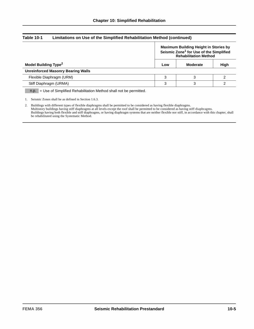
Chapter 10: Simplified Rehabilitation
Unreinforced Masonry Bearing Walls
Flexible Diaphragm (URM) 3 3 2
Stiff Diaphragm (URMA) 3 3 2
Table 10-1 Limitations on Use of the Simplified Rehabilitation Method (continued)
Model Building Type2
Maximum Building Height in Stories by Seismic Zone1 for Use of the Simplified
Rehabilitation Method
Low Moderate High
= Use of Simplified Rehabilitation Method shall not be permitted.
1. Seismic Zones shall be as defined in Section 1.6.3.
2. Buildings with different types of flexible diaphragms shall be permitted to be considered as having flexible diaphragms.Multistory buildings having stiff diaphragms at all levels except the roof shall be permitted to be considered as having stiff diaphragms.Buildings having both flexible and stiff diaphragms, or having diaphragm systems that are neither flexible nor stiff, in accordance with this chapter, shallbe rehabilitated using the Systematic Method.
n.p.
FEMA 356 Seismic Rehabilitation Prestandard 10-5
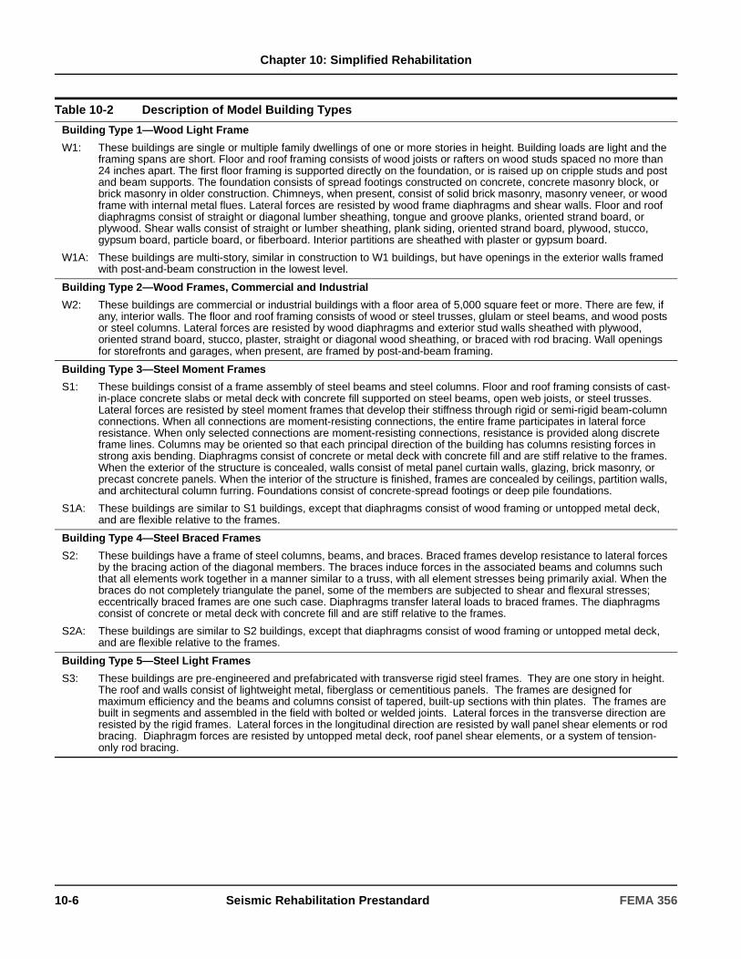
Chapter 10: Simplified Rehabilitation
Table 10-2 Description of Model Building Types
Building Type 1—Wood Light Frame
W1: These buildings are single or multiple family dwellings of one or more stories in height. Building loads are light and the framing spans are short. Floor and roof framing consists of wood joists or rafters on wood studs spaced no more than 24 inches apart. The first floor framing is supported directly on the foundation, or is raised up on cripple studs and post and beam supports. The foundation consists of spread footings constructed on concrete, concrete masonry block, or brick masonry in older construction. Chimneys, when present, consist of solid brick masonry, masonry veneer, or wood frame with internal metal flues. Lateral forces are resisted by wood frame diaphragms and shear walls. Floor and roof diaphragms consist of straight or diagonal lumber sheathing, tongue and groove planks, oriented strand board, or plywood. Shear walls consist of straight or lumber sheathing, plank siding, oriented strand board, plywood, stucco, gypsum board, particle board, or fiberboard. Interior partitions are sheathed with plaster or gypsum board.
W1A: These buildings are multi-story, similar in construction to W1 buildings, but have openings in the exterior walls framed with post-and-beam construction in the lowest level.
Building Type 2—Wood Frames, Commercial and Industrial
W2: These buildings are commercial or industrial buildings with a floor area of 5,000 square feet or more. There are few, if any, interior walls. The floor and roof framing consists of wood or steel trusses, glulam or steel beams, and wood posts or steel columns. Lateral forces are resisted by wood diaphragms and exterior stud walls sheathed with plywood, oriented strand board, stucco, plaster, straight or diagonal wood sheathing, or braced with rod bracing. Wall openings for storefronts and garages, when present, are framed by post-and-beam framing.
Building Type 3—Steel Moment Frames
S1: These buildings consist of a frame assembly of steel beams and steel columns. Floor and roof framing consists of cast-in-place concrete slabs or metal deck with concrete fill supported on steel beams, open web joists, or steel trusses. Lateral forces are resisted by steel moment frames that develop their stiffness through rigid or semi-rigid beam-column connections. When all connections are moment-resisting connections, the entire frame participates in lateral force resistance. When only selected connections are moment-resisting connections, resistance is provided along discrete frame lines. Columns may be oriented so that each principal direction of the building has columns resisting forces in strong axis bending. Diaphragms consist of concrete or metal deck with concrete fill and are stiff relative to the frames. When the exterior of the structure is concealed, walls consist of metal panel curtain walls, glazing, brick masonry, or precast concrete panels. When the interior of the structure is finished, frames are concealed by ceilings, partition walls, and architectural column furring. Foundations consist of concrete-spread footings or deep pile foundations.
S1A: These buildings are similar to S1 buildings, except that diaphragms consist of wood framing or untopped metal deck, and are flexible relative to the frames.
Building Type 4—Steel Braced Frames
S2: These buildings have a frame of steel columns, beams, and braces. Braced frames develop resistance to lateral forces by the bracing action of the diagonal members. The braces induce forces in the associated beams and columns such that all elements work together in a manner similar to a truss, with all element stresses being primarily axial. When the braces do not completely triangulate the panel, some of the members are subjected to shear and flexural stresses; eccentrically braced frames are one such case. Diaphragms transfer lateral loads to braced frames. The diaphragms consist of concrete or metal deck with concrete fill and are stiff relative to the frames.
S2A: These buildings are similar to S2 buildings, except that diaphragms consist of wood framing or untopped metal deck, and are flexible relative to the frames.
Building Type 5—Steel Light Frames
S3: These buildings are pre-engineered and prefabricated with transverse rigid steel frames. They are one story in height. The roof and walls consist of lightweight metal, fiberglass or cementitious panels. The frames are designed for maximum efficiency and the beams and columns consist of tapered, built-up sections with thin plates. The frames are built in segments and assembled in the field with bolted or welded joints. Lateral forces in the transverse direction are resisted by the rigid frames. Lateral forces in the longitudinal direction are resisted by wall panel shear elements or rod bracing. Diaphragm forces are resisted by untopped metal deck, roof panel shear elements, or a system of tension-only rod bracing.
10-6 Seismic Rehabilitation Prestandard FEMA 356
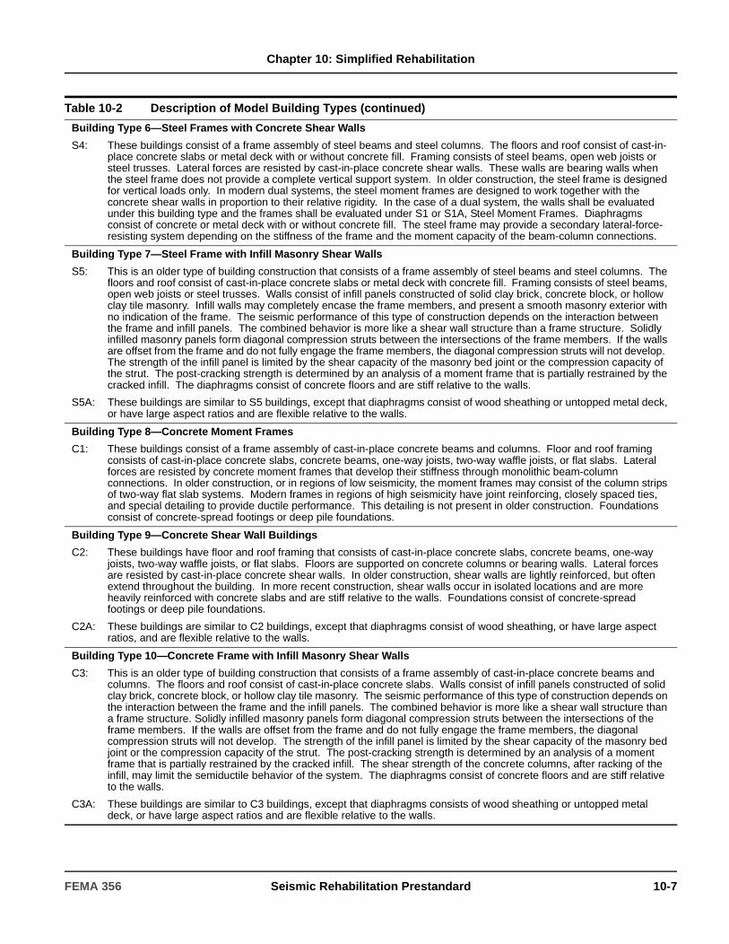
Chapter 10: Simplified Rehabilitation
Building Type 6—Steel Frames with Concrete Shear Walls
S4: These buildings consist of a frame assembly of steel beams and steel columns. The floors and roof consist of cast-in-place concrete slabs or metal deck with or without concrete fill. Framing consists of steel beams, open web joists or steel trusses. Lateral forces are resisted by cast-in-place concrete shear walls. These walls are bearing walls when the steel frame does not provide a complete vertical support system. In older construction, the steel frame is designed for vertical loads only. In modern dual systems, the steel moment frames are designed to work together with the concrete shear walls in proportion to their relative rigidity. In the case of a dual system, the walls shall be evaluated under this building type and the frames shall be evaluated under S1 or S1A, Steel Moment Frames. Diaphragms consist of concrete or metal deck with or without concrete fill. The steel frame may provide a secondary lateral-force-resisting system depending on the stiffness of the frame and the moment capacity of the beam-column connections.
Building Type 7—Steel Frame with Infill Masonry Shear Walls
S5: This is an older type of building construction that consists of a frame assembly of steel beams and steel columns. The floors and roof consist of cast-in-place concrete slabs or metal deck with concrete fill. Framing consists of steel beams, open web joists or steel trusses. Walls consist of infill panels constructed of solid clay brick, concrete block, or hollow clay tile masonry. Infill walls may completely encase the frame members, and present a smooth masonry exterior with no indication of the frame. The seismic performance of this type of construction depends on the interaction between the frame and infill panels. The combined behavior is more like a shear wall structure than a frame structure. Solidly infilled masonry panels form diagonal compression struts between the intersections of the frame members. If the walls are offset from the frame and do not fully engage the frame members, the diagonal compression struts will not develop. The strength of the infill panel is limited by the shear capacity of the masonry bed joint or the compression capacity of the strut. The post-cracking strength is determined by an analysis of a moment frame that is partially restrained by the cracked infill. The diaphragms consist of concrete floors and are stiff relative to the walls.
S5A: These buildings are similar to S5 buildings, except that diaphragms consist of wood sheathing or untopped metal deck, or have large aspect ratios and are flexible relative to the walls.
Building Type 8—Concrete Moment Frames
C1: These buildings consist of a frame assembly of cast-in-place concrete beams and columns. Floor and roof framing consists of cast-in-place concrete slabs, concrete beams, one-way joists, two-way waffle joists, or flat slabs. Lateral forces are resisted by concrete moment frames that develop their stiffness through monolithic beam-column connections. In older construction, or in regions of low seismicity, the moment frames may consist of the column strips of two-way flat slab systems. Modern frames in regions of high seismicity have joint reinforcing, closely spaced ties, and special detailing to provide ductile performance. This detailing is not present in older construction. Foundations consist of concrete-spread footings or deep pile foundations.
Building Type 9—Concrete Shear Wall Buildings
C2: These buildings have floor and roof framing that consists of cast-in-place concrete slabs, concrete beams, one-way joists, two-way waffle joists, or flat slabs. Floors are supported on concrete columns or bearing walls. Lateral forces are resisted by cast-in-place concrete shear walls. In older construction, shear walls are lightly reinforced, but often extend throughout the building. In more recent construction, shear walls occur in isolated locations and are more heavily reinforced with concrete slabs and are stiff relative to the walls. Foundations consist of concrete-spread footings or deep pile foundations.
C2A: These buildings are similar to C2 buildings, except that diaphragms consist of wood sheathing, or have large aspect ratios, and are flexible relative to the walls.
Building Type 10—Concrete Frame with Infill Masonry Shear Walls
C3: This is an older type of building construction that consists of a frame assembly of cast-in-place concrete beams and columns. The floors and roof consist of cast-in-place concrete slabs. Walls consist of infill panels constructed of solid clay brick, concrete block, or hollow clay tile masonry. The seismic performance of this type of construction depends on the interaction between the frame and the infill panels. The combined behavior is more like a shear wall structure than a frame structure. Solidly infilled masonry panels form diagonal compression struts between the intersections of the frame members. If the walls are offset from the frame and do not fully engage the frame members, the diagonal compression struts will not develop. The strength of the infill panel is limited by the shear capacity of the masonry bed joint or the compression capacity of the strut. The post-cracking strength is determined by an analysis of a moment frame that is partially restrained by the cracked infill. The shear strength of the concrete columns, after racking of the infill, may limit the semiductile behavior of the system. The diaphragms consist of concrete floors and are stiff relative to the walls.
C3A: These buildings are similar to C3 buildings, except that diaphragms consists of wood sheathing or untopped metal deck, or have large aspect ratios and are flexible relative to the walls.
Table 10-2 Description of Model Building Types (continued)
FEMA 356 Seismic Rehabilitation Prestandard 10-7
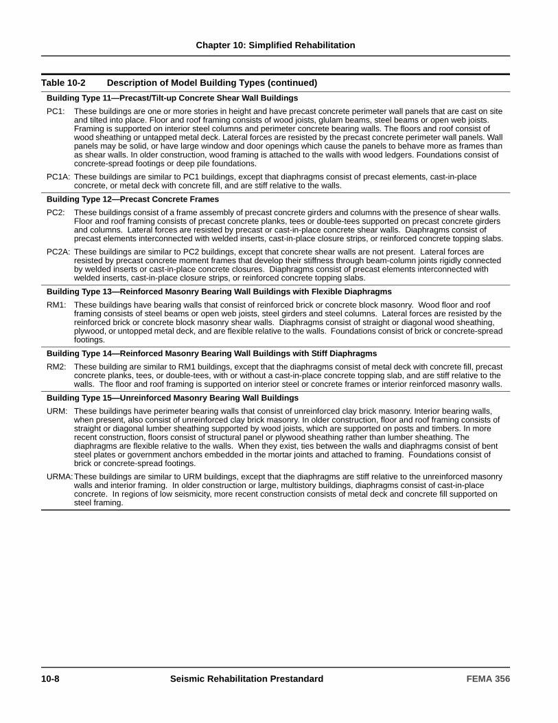
Chapter 10: Simplified Rehabilitation
Building Type 11—Precast/Tilt-up Concrete Shear Wall Buildings
PC1: These buildings are one or more stories in height and have precast concrete perimeter wall panels that are cast on site and tilted into place. Floor and roof framing consists of wood joists, glulam beams, steel beams or open web joists. Framing is supported on interior steel columns and perimeter concrete bearing walls. The floors and roof consist of wood sheathing or untapped metal deck. Lateral forces are resisted by the precast concrete perimeter wall panels. Wall panels may be solid, or have large window and door openings which cause the panels to behave more as frames than as shear walls. In older construction, wood framing is attached to the walls with wood ledgers. Foundations consist of concrete-spread footings or deep pile foundations.
PC1A: These buildings are similar to PC1 buildings, except that diaphragms consist of precast elements, cast-in-place concrete, or metal deck with concrete fill, and are stiff relative to the walls.
Building Type 12—Precast Concrete Frames
PC2: These buildings consist of a frame assembly of precast concrete girders and columns with the presence of shear walls. Floor and roof framing consists of precast concrete planks, tees or double-tees supported on precast concrete girders and columns. Lateral forces are resisted by precast or cast-in-place concrete shear walls. Diaphragms consist of precast elements interconnected with welded inserts, cast-in-place closure strips, or reinforced concrete topping slabs.
PC2A: These buildings are similar to PC2 buildings, except that concrete shear walls are not present. Lateral forces are resisted by precast concrete moment frames that develop their stiffness through beam-column joints rigidly connected by welded inserts or cast-in-place concrete closures. Diaphragms consist of precast elements interconnected with welded inserts, cast-in-place closure strips, or reinforced concrete topping slabs.
Building Type 13—Reinforced Masonry Bearing Wall Buildings with Flexible Diaphragms
RM1: These buildings have bearing walls that consist of reinforced brick or concrete block masonry. Wood floor and roof framing consists of steel beams or open web joists, steel girders and steel columns. Lateral forces are resisted by the reinforced brick or concrete block masonry shear walls. Diaphragms consist of straight or diagonal wood sheathing, plywood, or untopped metal deck, and are flexible relative to the walls. Foundations consist of brick or concrete-spread footings.
Building Type 14—Reinforced Masonry Bearing Wall Buildings with Stiff Diaphragms
RM2: These building are similar to RM1 buildings, except that the diaphragms consist of metal deck with concrete fill, precast concrete planks, tees, or double-tees, with or without a cast-in-place concrete topping slab, and are stiff relative to the walls. The floor and roof framing is supported on interior steel or concrete frames or interior reinforced masonry walls.
Building Type 15—Unreinforced Masonry Bearing Wall Buildings
URM: These buildings have perimeter bearing walls that consist of unreinforced clay brick masonry. Interior bearing walls, when present, also consist of unreinforced clay brick masonry. In older construction, floor and roof framing consists of straight or diagonal lumber sheathing supported by wood joists, which are supported on posts and timbers. In more recent construction, floors consist of structural panel or plywood sheathing rather than lumber sheathing. The diaphragms are flexible relative to the walls. When they exist, ties between the walls and diaphragms consist of bent steel plates or government anchors embedded in the mortar joints and attached to framing. Foundations consist of brick or concrete-spread footings.
URMA:These buildings are similar to URM buildings, except that the diaphragms are stiff relative to the unreinforced masonry walls and interior framing. In older construction or large, multistory buildings, diaphragms consist of cast-in-place concrete. In regions of low seismicity, more recent construction consists of metal deck and concrete fill supported on steel framing.
Table 10-2 Description of Model Building Types (continued)
10-8 Seismic Rehabilitation Prestandard FEMA 356

Chapter 10: Simplified Rehabilitation
10.3 Correction of DeficienciesFor Simplified Rehabilitation, deficiencies identified by an FEMA 310 Evaluation shall be mitigated by implementing approved rehabilitation measures. The resulting building, including strengthening measures, shall comply with the requirements of FEMA 310 and shall conform to one of the Model Building Types contained in Table 10-1, except that steel bracing in wood or unreinforced masonry buildings shall be permitted.
The Simplified Rehabilitation Method shall only be used to achieve Limited Rehabilitation Objectives. To achieve the Life Safety Building Performance Level (3-C) at the BSE-1 Earthquake Hazard Level, all deficiencies identified by an FEMA 310 Evaluation shall be corrected to meet the FEMA 310 criteria. To achieve a Partial Rehabilitation Objective, only selected deficiencies need be corrected.
To achieve the Basic Safety Objective, the Simplified Rehabilitation Method is not permitted, and deficiencies shall be corrected in accordance with the Systematic Rehabilitation Method of Section 2.3.
C10.3 Correction of DeficienciesImplementing a rehabilitation scheme that mitigates all of a building’s FEMA 310 deficiencies using the Simplified Rehabilitation Method does not, in and of itself, achieve the Basic Safety Objective or any Enhanced Rehabilitation Objective as defined in Chapter 2 since the rehabilitated building may not meet the Collapse Prevention Structural Performance Level for the BSE-2 Earthquake Hazard Level. If the goal is to attain the Basic Safety Objective as described in Chapter 2 or other Enhanced Rehabilitation Objectives, this can be accomplished using the Systematic Rehabilitation Method defined in Chapter 2.
Suggested rehabilitation measures are listed by deficiency in the following sections.
C10.3.1 Building Systems
C10.3.1.1 Load Path
Load path discontinuities can be mitigated by adding elements to complete the load path. This may require adding new well-founded shear walls or frames to fill gaps in existing shear walls or frames that are not carried continuously to the foundation. Alternatively, it may require the addition of elements throughout the building to pick up loads from diaphragms that have no path into existing vertical elements (FEMA 310, Section 4.3.1).
C10.3.1.2 Redundancy
The most prudent rehabilitation strategy for a building without redundancy is to add new lateral-force-resisting elements in locations where the failure of a single element will cause an instability in the building. The added lateral-force-resisting elements should be of the same stiffness as the elements they are supplementing. It is not generally satisfactory just to strengthen a non-redundant element (such as by adding cover plates to a slender brace), because its failure would still result in an instability (FEMA 310, Sections 4.4.1.1.1, 4.4.2.1.1, 4.4.3.1.1, 4.4.4.1.1).
C10.3.1.3 Vertical Irregularities
New vertical lateral-force-resisting elements can be provided to eliminate the vertical irregularity. For weak stories, soft stories, and vertical discontinuities, new elements of the same type can be added as needed. Mass and geometric discontinuities must be evaluated and strengthened based on the Systematic Rehabilitation Method, if required by Chapter 2 (FEMA 310, Sections 4.3.2.4–4.3.2.5).
C10.3.1.4 Plan Irregularities
The effects of plan irregularities that create torsion can be eliminated with the addition of lateral-force-resisting bracing elements that will support all major diaphragm segments in a balanced manner. While it is possible in some cases to allow the irregularity to remain and instead strengthen those structural elements that are overstressed by its existence, this does not directly address the problem and will require the use of the Systematic Rehabilitation Method (FEMA 310, Section 4.3.2.6).
FEMA 356 Seismic Rehabilitation Prestandard 10-9
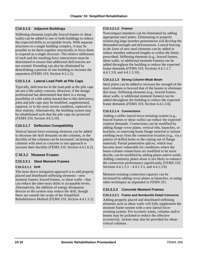
Chapter 10: Simplified Rehabilitation
C10.3.1.5 Adjacent Buildings
Stiffening elements (typically braced frames or shear walls) can be added to one or both buildings to reduce the expected drifts to acceptable levels. With separate structures in a single building complex, it may be possible to tie them together structurally to force them to respond as a single structure. The relative stiffnesses of each and the resulting force interactions must be determined to ensure that additional deficiencies are not created. Pounding can also be eliminated by demolishing a portion of one building to increase the separation (FEMA 310, Section 4.3.1.2).
C10.3.1.6 Lateral Load Path at Pile Caps
Typically, deficiencies in the load path at the pile caps are not a life safety concern. However, if the design professional has determined that there is a strong possibility of a life safety hazard due to this deficiency, piles and pile caps may be modified, supplemented, repaired, or in the most severe condition, replaced in their entirety. Alternatively, the building system may be rehabilitated such that the pile caps are protected (FEMA 310, Section 4.6.3.10).
C10.3.1.7 Deflection Compatibility
Vertical lateral-force-resisting elements can be added to decrease the drift demands on the columns, or the ductility of the columns can be increased. Jacketing the columns with steel or concrete is one approach to increase their ductility (FEMA 310, Section 4.4.1.6.2).
C10.3.2 Moment Frames
C10.3.2.1 Steel Moment Frames
C10.3.2.1.1 Drift
The most direct mitigation approach is to add properly placed and distributed stiffening elements—new moment frames, braced frames, or shear walls—that can reduce the inter-story drifts to acceptable levels. Alternatively, the addition of energy dissipation devices to the system may reduce the drift, though these are outside the scope of the Simplified Rehabilitation Method (FEMA 310, Section 4.4.1.3.1).
C10.3.2.1.2 Frames
Noncompact members can be eliminated by adding appropriate steel plates. Eliminating or properly reinforcing large member penetrations will develop the demanded strength and deformations. Lateral bracing in the form of new steel elements can be added to reduce member unbraced lengths to within the limits prescribed. Stiffening elements (e.g., braced frames, shear walls, or additional moment frames) can be added throughout the building to reduce the expected frame demands (FEMA 310, Sections 4.4.1.3.7, 4.4.1.3.8, and 4.4.1.3.10).
C10.3.2.1.3 Strong Column-Weak Beam
Steel plates can be added to increase the strength of the steel columns to beyond that of the beams to eliminate this issue. Stiffening elements (e.g., braced frames, shear walls, or additional moment frames) can be added throughout the building to reduce the expected frame demands (FEMA 310, Section 4.4.1.3.6).
C10.3.2.1.4 Connections
Adding a stiffer lateral-force-resisting system (e.g., braced frames or shear walls) can reduce the expected rotation demands. Connections can be modified by adding flange cover plates, vertical ribs, haunches, or brackets, or removing beam flange material to initiate yielding away from the connection location (e.g., via a pattern of drilled holes or the cutting out of flange material). Partial penetration splices, which may become more vulnerable for conditions where the beam-column connections are modified to be more ductile, can be modified by adding plates and/or welds. Adding continuity plates alone is not likely to enhance the connection performance significantly (FEMA 310, Sections 4.4.1.3.3 – 4.4.1.3.5, and 4.4.1.3.9).
Moment-resisting connection capacity can be increased by adding cover plates or haunches, or using other techniques as stipulated in FEMA 351.
C10.3.2.2 Concrete Moment Frames
C10.3.2.2.1 Frame and Nonductile Detail Concerns
Adding properly placed and distributed stiffening elements such as shear walls will fully supplement the moment frame system with a new lateral force-resisting system. For eccentric joints, columns and/or beams may be jacketed to reduce the effective eccentricity. Jackets may also be provided for shear-critical columns.
10-10 Seismic Rehabilitation Prestandard FEMA 356
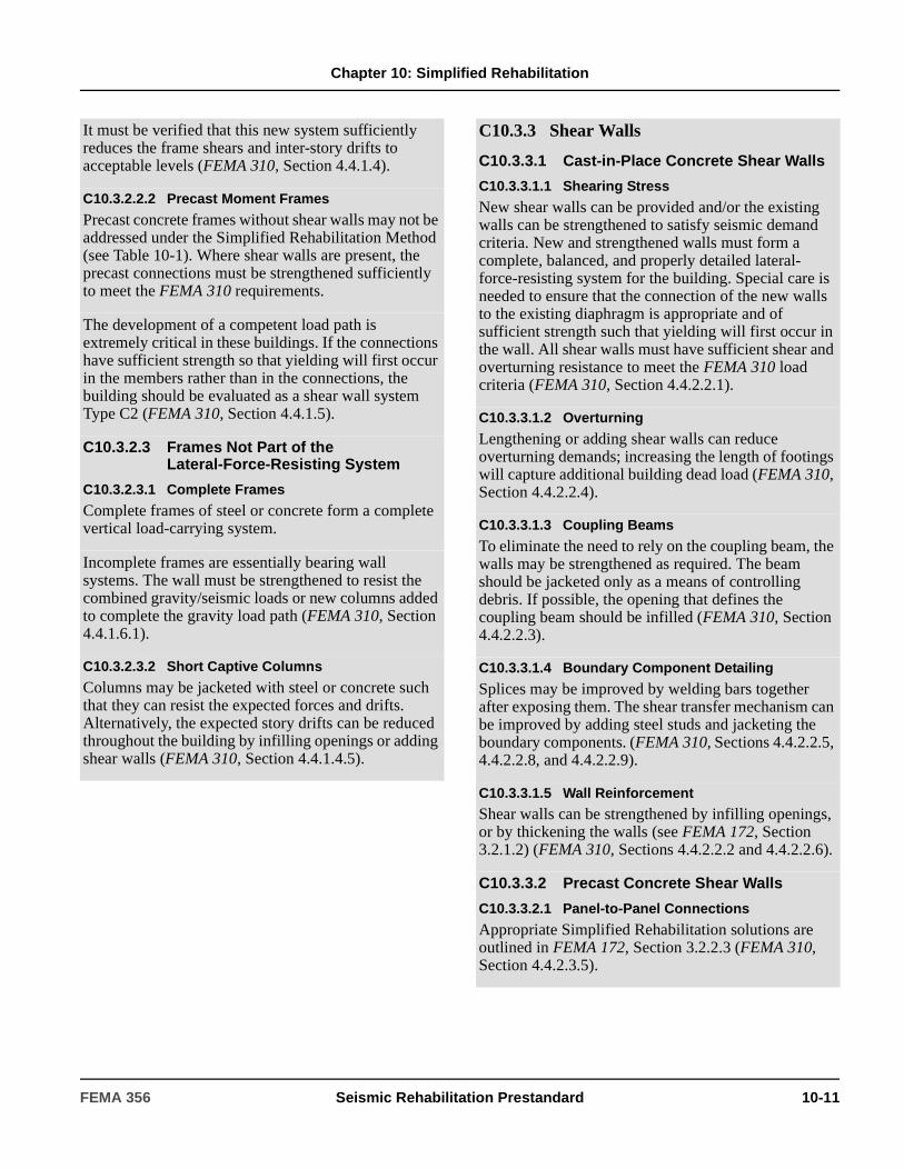
Chapter 10: Simplified Rehabilitation
It must be verified that this new system sufficiently reduces the frame shears and inter-story drifts to acceptable levels (FEMA 310, Section 4.4.1.4).
C10.3.2.2.2 Precast Moment Frames
Precast concrete frames without shear walls may not be addressed under the Simplified Rehabilitation Method (see Table 10-1). Where shear walls are present, the precast connections must be strengthened sufficiently to meet the FEMA 310 requirements.
The development of a competent load path is extremely critical in these buildings. If the connections have sufficient strength so that yielding will first occur in the members rather than in the connections, the building should be evaluated as a shear wall system Type C2 (FEMA 310, Section 4.4.1.5).
C10.3.2.3 Frames Not Part of the Lateral-Force-Resisting System
C10.3.2.3.1 Complete Frames
Complete frames of steel or concrete form a complete vertical load-carrying system.
Incomplete frames are essentially bearing wall systems. The wall must be strengthened to resist the combined gravity/seismic loads or new columns added to complete the gravity load path (FEMA 310, Section 4.4.1.6.1).
C10.3.2.3.2 Short Captive Columns
Columns may be jacketed with steel or concrete such that they can resist the expected forces and drifts. Alternatively, the expected story drifts can be reduced throughout the building by infilling openings or adding shear walls (FEMA 310, Section 4.4.1.4.5).
C10.3.3 Shear Walls
C10.3.3.1 Cast-in-Place Concrete Shear Walls
C10.3.3.1.1 Shearing Stress
New shear walls can be provided and/or the existing walls can be strengthened to satisfy seismic demand criteria. New and strengthened walls must form a complete, balanced, and properly detailed lateral-force-resisting system for the building. Special care is needed to ensure that the connection of the new walls to the existing diaphragm is appropriate and of sufficient strength such that yielding will first occur in the wall. All shear walls must have sufficient shear and overturning resistance to meet the FEMA 310 load criteria (FEMA 310, Section 4.4.2.2.1).
C10.3.3.1.2 Overturning
Lengthening or adding shear walls can reduce overturning demands; increasing the length of footings will capture additional building dead load (FEMA 310, Section 4.4.2.2.4).
C10.3.3.1.3 Coupling Beams
To eliminate the need to rely on the coupling beam, the walls may be strengthened as required. The beam should be jacketed only as a means of controlling debris. If possible, the opening that defines the coupling beam should be infilled (FEMA 310, Section 4.4.2.2.3).
C10.3.3.1.4 Boundary Component Detailing
Splices may be improved by welding bars together after exposing them. The shear transfer mechanism can be improved by adding steel studs and jacketing the boundary components. (FEMA 310, Sections 4.4.2.2.5, 4.4.2.2.8, and 4.4.2.2.9).
C10.3.3.1.5 Wall Reinforcement
Shear walls can be strengthened by infilling openings, or by thickening the walls (see FEMA 172, Section 3.2.1.2) (FEMA 310, Sections 4.4.2.2.2 and 4.4.2.2.6).
C10.3.3.2 Precast Concrete Shear Walls
C10.3.3.2.1 Panel-to-Panel Connections
Appropriate Simplified Rehabilitation solutions are outlined in FEMA 172, Section 3.2.2.3 (FEMA 310, Section 4.4.2.3.5).
FEMA 356 Seismic Rehabilitation Prestandard 10-11

Chapter 10: Simplified Rehabilitation
Inter-panel connections with inadequate capacity can be strengthened by adding steel plates across the joint, or by providing a continuous wall by exposing the reinforcing steel in the adjacent units and providing ties between the panels and patching with concrete. Providing steel plates across the joint is typically the most cost-effective approach, although care must be taken to ensure adequate anchor bolt capacity by providing adequate edge distances (see FEMA 172, Section 3.2.2).
C10.3.3.2.2 Wall Openings
Infilling openings or adding shear walls in the plane of the open bays can reduce demand on the connections and eliminate frame action (FEMA 310, Section 4.4.2.3.3).
C10.3.3.2.3 Collectors
Upgrading the concrete section and/or the connections (e.g., exposing the existing connection, adding confinement ties, increasing embedment) can increase strength and/or ductility. Alternative load paths for lateral forces can be provided, and shear walls can be added to reduce demand on the existing collectors (FEMA 310, Section 4.4.2.3.4).
C10.3.3.3 Masonry Shear Walls
C10.3.3.3.1 Reinforcing in Masonry Walls
Nondestructive methods should be used to locate reinforcement, and selective demolition used if necessary to determine the size and spacing of the reinforcing. If it cannot be verified that the wall is reinforced in accordance with the minimum requirements, then the wall should be assumed to be unreinforced, and therefore must be supplemented with new walls, or the procedures for unreinforced masonry should be followed (FEMA 310, Section 4.4.2.4.2).
C10.3.3.3.2 Shearing Stress
To meet the lateral force requirements of FEMA 310, new walls can be provided or the existing walls can be strengthened as needed. New and strengthened walls must form a complete, balanced, and properly detailed lateral-force-resisting system for the building. Special care is needed to ensure that the connection of the new walls to the existing diaphragm is appropriate and of sufficient strength to deliver the actual lateral loads or force yielding in the wall. All shear walls must have sufficient shear and overturning resistance (FEMA 310, Section 4.4.2.4.1).
C10.3.3.3.3 Reinforcing at Openings
The presence and location of reinforcing steel at openings may be established using nondestructive or destructive methods at selected locations to verify the size and location of the reinforcing, or using both methods. Reinforcing must be provided at all openings as required to meet the FEMA 310 criteria. Steel plates may be bolted to the surface of the section as long as the bolts are sufficient to yield the steel plate (FEMA 310, Section 4.4.2.4.3).
C10.3.3.3.4 Unreinforced Masonry Shear Walls
Openings in the lateral-force-resisting walls should be infilled as needed to meet the FEMA 310 stress check. If supplemental strengthening is required, it should be designed using the Systematic Rehabilitation Method as defined in Chapter 2. Walls that do not meet the masonry lay-up requirements should not be considered as lateral force-resisting elements and shall be specially supported for out-of-plane loads (FEMA 310, Sections 4.4.2.5.1 and 4.4.2.5.3).
C10.3.3.3.5 Proportions of Solid Walls
Walls with insufficient thickness should be strengthened either by increasing the thickness of the wall or by adding a well-detailed strong back system. The thickened wall must be detailed in a manner that fully interconnects the wall over its full height. The strong back system must be designed for strength, connected to the structure in a manner that: (1) develops the full yield strength of the strong back, and (2) connects to the diaphragm in a manner that distributes the load into the diaphragm and has sufficient stiffness to ensure that the elements will perform in a compatible and acceptable manner. The stiffness of the bracing should limit the out-of-plane deflections to acceptable levels such as L/600 to L/900 (FEMA 310, Sections 4.4.2.4.4 and 4.4.2.5.2).
C10.3.3.3.6 Infill Walls
The partial infill wall should be isolated from the boundary columns to avoid a “short column” effect, except when it can be shown that the column is adequate. In sizing the gap between the wall and the columns, the anticipated inter-story drift must be considered. The wall must be positively restrained against out-of-plane failure by either bracing the top of the wall or installing vertical girts. These bracing elements must not violate the isolation of the frame from the infill (FEMA 310, Section 4.4.2.6).
10-12 Seismic Rehabilitation Prestandard FEMA 356
Chapter 10: Simplified Rehabilitation
C10.3.3.4 Shear Walls in Wood Frame Buildings
C10.3.3.4.1 Shear Stress
Walls may be added or existing openings filled. Alternatively, the existing walls and connections can be strengthened. The walls should be distributed across the building in a balanced manner to reduce the shear stress for each wall. Replacing heavy materials such as tile roofing with lighter materials will also reduce shear stress. (FEMA 310, Section 4.4.2.7.1).
C10.3.3.4.2 Openings
Local shear transfer stresses can be reduced by distributing the forces from the diaphragm. Chords and/or collector members can be provided to collect and distribute shear from the diaphragm to the shear wall or bracing (see FEMA 172, Figure 3.7.1.3). Alternatively, the opening can be closed off by adding a new wall with plywood sheathing. (FEMA 310, Section 4.4.2.7.8).
C10.3.3.4.3 Wall Detailing
If the walls are not bolted to the foundation or if the bolting is inadequate, bolts can be installed through the sill plates at regular intervals (see FEMA 172, Figure 3.8.1.2a). If the crawl space is not deep enough for vertical holes to be drilled through the sill plate, the installation of connection plates or angles may be a practical alternative (see FEMA 172, Figure 3.8.1.2b). Sheathing and additional nailing can be added where walls lack proper nailing or connections. Where the existing connections are inadequate, adding clips or straps will deliver lateral loads to the walls and to the foundation sill plate (FEMA 310, Section 4.4.2.7.9).
C10.3.3.4.4 Cripple Walls
Where bracing is inadequate, new plywood sheathing can be added to the cripple wall studs. The top edge of the plywood is nailed to the floor framing and the bottom edge is nailed into the sill plate (see FEMA 172, Figure 3.8.1.3). Verify that the cripple wall does not change height along its length (stepped top of foundation). If it does, the shorter portion of the cripple wall will carry the majority of the shear and significant torsion will occur in the foundation. Added plywood sheathing must have adequate strength and stiffness to reduce torsion to an acceptable level. Also, it should be verified that the sill plate is properly anchored to the foundation. If anchor bolts are lacking or insufficient, additional anchor bolts should be installed. Blocking and/or framing clips may be needed to connect the cripple wall bracing to the floor diaphragm or the sill plate. (FEMA 310, Section 4.4.2.7.7).
C10.3.3.4.5 Narrow Wood Shear Walls
Where narrow shear walls lack capacity, they should be replaced with shear walls with a height-to-width aspect ratio of two-to-one or less. These replacement walls must have sufficient strength, including being adequately connected to the diaphragm and sufficiently anchored to the foundation for shear and overturning forces (FEMA 310, Section 4.4.2.7.4).
C10.3.3.4.6 Stucco Shear Walls
For strengthening or repair, the stucco should be removed, a plywood shear wall added, and new stucco applied. The plywood should be the manufacturer’s recommended thickness for the installation of stucco. The new stucco should be installed in accordance with building code requirements for waterproofing. Walls should be sufficiently anchored to the diaphragm and foundation (FEMA 310, Section 4.4.2.7.2).
C10.3.3.4.7 Gypsum Wallboard or Plaster Shear Walls
Plaster and gypsum wallboard can be removed and replaced with structural panel shear wall as required, and the new shear walls covered with gypsum wallboard (FEMA 310, Section 4.4.2.7.3).
FEMA 356 Seismic Rehabilitation Prestandard 10-13
Chapter 10: Simplified Rehabilitation
C10.3.4 Steel Braced Frames
C10.3.4.1 System Concerns
If the strength of the braced frames is inadequate, more braced bays or shear wall panels can be added. The resulting lateral-force-resisting system must form a well-balanced system of braced frames that do not fail at their joints, are properly connected to the floor diaphragms, and whose failure mode is yielding of braces rather than overturning (FEMA 310, Sections 4.4.3.1.1 and 4.4.3.1.2).
C10.3.4.2 Stiffness of Diagonals
Diagonals with inadequate stiffness should be strengthened using supplemental steel plates, or replaced with a larger and/or different type of section. Global stiffness can be increased by the addition of braced bays or shear wall panels (FEMA 310, Sections 4.4.3.1.3 and 4.4.3.2.2).
C10.3.4.3 Chevron or K-Bracing
Columns or horizontal girts can be added as needed to support the tension brace when the compression brace buckles, or the bracing can be revised to another system throughout the building. The beam elements can be strengthened with cover plates to provide them with the capacity to fully develop the unbalanced forces created by tension brace yielding (FEMA 310, Sections 4.4.3.2.1 and 4.4.3.2.3).
C10.3.4.4 Braced Frame Connections
Column splices or other braced frame connections can be strengthened by adding plates and welds to ensure that they are strong enough to develop the connected members. Connection eccentricities that reduce member capacities can be eliminated, or the members can be strengthened to the required level by the addition of properly placed plates. Demands on the existing elements can be reduced by adding braced bays or shear wall panels (FEMA 310, Sections 4.4.3.1.4 and 4.4.3.1.5).
C10.3.5 Diaphragms
C10.3.5.1 Re-entrant Corners
New chords with sufficient strength to resist the required force can be added at the re-entrant corner. If a vertical lateral-force-resisting element exists at the re-entrant corner, a new collector element should be installed in the diaphragm to reduce tensile and compressive forces at the re-entrant corner. The same basic materials used in the diaphragm should be used for the chord (FEMA 310, Section 4.5.1.7).
C10.3.5.2 Cross Ties
New cross ties and wall connections can be added to resist the required out-of-plane wall forces and distribute these forces through the diaphragm. New strap plates and/or rod connections can be used to connect existing framing members together so they function as a crosstie in the diaphragm (FEMA 310, Section 4.5.1.2).
C10.3.5.3 Diaphragm Openings
New drag struts or diaphragm chords can be added around the perimeter of existing openings to distribute tension and compression forces along the diaphragm. The existing sheathing should be nailed to the new drag struts or diaphragm chords. In some cases it may also be necessary to: (1) increase the shear capacity of the diaphragm adjacent to the opening by overlaying the existing diaphragm with a wood structural panel, or (2) decrease the demand on the diaphragm by adding new vertical elements near the opening (FEMA 310, Sections 4.5.1.4 through 4.5.1.6 and 4.5.1.8).
C10.3.5.4 Diaphragm Stiffness/Strength
C10.3.5.4.1 Board Sheathing
When the diaphragm does not have at least two nails through each board into each of the supporting members, and the lateral drift and/or shear demands on the diaphragm are not excessive, the shear capacity and stiffness of the diaphragm can be increased by adding nails at the sheathing boards. This method of upgrade is most often suitable in areas of low seismicity. In other cases, a new wood structural panel should be placed over the existing straight sheathing, and the joints of the wood structural panels placed so they are near the center of the sheathing boards or at a 45-degree angle to the joints between sheathing boards (see FEMA 172, Section 3.5.1.2; ATC-7, and FEMA 310, Section 4.5.2.1).
10-14 Seismic Rehabilitation Prestandard FEMA 356
Chapter 10: Simplified Rehabilitation
C10.3.5.4.2 Unblocked Diaphragm
The shear capacity of unblocked diaphragms can be improved by adding new wood blocking and nailing at the unsupported panel edges. Placing a new wood structural panel over the existing diaphragm will increase the shear capacity. Both of these methods will require the partial or total removal of existing flooring or roofing to place and nail the new overlay or nail the existing panels to the new blocking. Strengthening of the diaphragm is usually not necessary at the central area of the diaphragm where shear is low. In certain cases when the design loads are low, it may be possible to increase the shear capacity of unblocked diaphragms with sheet metal plates stapled on the underside of the existing wood panels. These plates and staples must be designed for all related shear and torsion caused by the details related to their installation (FEMA 310, Section 4.5.2.3).
C10.3.5.4.3 Spans
New vertical elements can be added to reduce the diaphragm span. The reduction of the diaphragm span will also reduce the lateral deflection and shear demand in the diaphragm. However, adding new vertical elements will result in a different distribution of shear demands. Additional blocking, nailing, or other rehabilitation measures may need to be provided at these areas (FEMA 172, Section 3.4 and FEMA 310, Section 4.5.2.2).
C10.3.5.4.4 Span-to-Depth Ratio
New vertical elements can be added to reduce the diaphragm span-to-depth ratio. The reduction of the diaphragm span-to-depth ratio will also reduce the lateral deflection and shear demand in the diaphragm. Typical construction details and methods are discussed in FEMA 172, Section 3.4.
C10.3.5.4.5 Diaphragm Continuity
The diaphragm discontinuity should in all cases be eliminated by adding new vertical elements at the diaphragm offset or the expansion joint (see FEMA 172, Section 3.4). In some cases, special details may be used to transfer shear across an expansion joint—while still allowing the expansion joint to function—thus eliminating a diaphragm discontinuity (FEMA 310, Section 4.5.1.1).
C10.3.5.4.6 Chord Continuity
If members such as edge joists, blocking, or wall top plates have the capacity to function as chords but lack connection, adding nailed or bolted continuity splices will provide a continuous diaphragm chord. New continuous steel or wood chord members can be added to the existing diaphragm where existing members lack sufficient capacity or no chord exists. New chord members can be placed at either the underside or topside of the diaphragm. In some cases, new vertical elements can be added to reduce the diaphragm span and stresses on any existing chord members (see FEMA 172, Section 3.5.1.3, and ATC-7). New chord connections should not be detailed such that they are the weakest element in the chord (FEMA 310, Section 4.5.1.3).
C10.3.6 Connections
C10.3.6.1 Diaphragm/Wall Shear Transfer
Collector members, splice plates, and shear transfer devices can be added as required to deliver collector forces to the shear wall. Adding shear connectors from the diaphragm to the wall and/or to the collectors will transfer shear. See FEMA 172, Section 3.7 for Wood Diaphragms, 3.7.2 for concrete diaphragms, 3.7.3 for poured gypsum, and 3.7.4 for metal deck diaphragms (FEMA 310, Sections 4.6.2.1 and 4.6.2.3).
C10.3.6.2 Diaphragm/Frame Shear Transfer
Adding collectors and connecting the framing will transfer loads to the collectors. Connections can be provided along the collector length and at the collector-to-frame connection to withstand the calculated forces. See FEMA 172, Sections 3.7.5 and 3.7.6 (FEMA 310, Sections 4.6.2.2 and 4.6.2.3).
C10.3.6.3 Anchorage for Normal Forces
To account for inadequacies identified by FEMA 310, wall anchors can be added. Complications that may result from inadequate anchorage include cross-grain tension in wood ledgers or failure of the diaphragm-to-wall connection due to: (1) insufficient strength, number, or stability of anchors; (2) inadequate embedment of anchors; (3) inadequate development of anchors and straps into the diaphragm; and (4) deformation of anchors and their fasteners that permit diaphragm boundary connection pullout, or cross-grain tension in wood ledgers.
FEMA 356 Seismic Rehabilitation Prestandard 10-15
Chapter 10: Simplified Rehabilitation
Existing anchors should be tested to determine load capacity and deformation potential, including fastener slip, according to the requirements in FEMA 310. Special attention should be given to the testing procedure to maintain a high level of quality control. Additional anchors should be provided as needed to supplement those that fail the test, as well as those needed to meet the FEMA 310 criteria. The quality of the rehabilitation depends greatly on the quality of the performed tests (FEMA 310, Sections 4.6.1.1 through 4.6.1.5).
C10.3.6.4 Girder-Wall Connections
The existing reinforcing must be exposed, and the connection modified as necessary. For out-of-plane loads, the number of column ties can be increased by jacketing the pilaster or, alternatively, by developing a second load path for the out-of-plane forces. Bearing length conditions can be addressed by adding bearing extensions. Frame action in welded connections can be mitigated by adding shear walls (FEMA 310, Section 4.6.4.1).
C10.3.6.5 Precast Connections
The connections of chords, ties, and collectors can be upgraded to increase strength and/or ductility, providing alternative load paths for lateral forces. Upgrading can be achieved by such methods as adding confinement ties or increasing embedment. Shear walls can be added to reduce the demand on connections (FEMA 310, Section 4.4.1.5.3).
C10.3.6.6 Wall Panels and Cladding
It may be possible to improve the connection between the panels and the framing. If architectural or occupancy conditions warrant, the cladding can be replaced with a new system. The building can be stiffened with the addition of shear walls or braced frames to reduce the drifts in the cladding elements (FEMA 310, Section 4.8.4.6).
C10.3.6.7 Light Gage Metal, Plastic, or Cementitious Roof Panels
It may be possible to improve the connection between the roof and the framing. If architectural or occupancy conditions warrant, the roof diaphragm can be replaced with a new one. Alternatively, a new diaphragm may be added using rod braces or plywood above or below the existing roof, which remains in place (FEMA 310, Section 4.6.5.1).
C10.3.6.8 Mezzanine Connections
Diagonal braces, moment frames, or shear walls can be added at or near the perimeter of the mezzanine where bracing elements are missing, so that a complete and balanced lateral-force-resisting system is provided that meets the requirements of FEMA 310 (FEMA 310, Section 4.3.1.3).
C10.3.7 Foundations and Geologic Hazards
C10.3.7.1 Anchorage to Foundations
For wood walls, expansion anchors or epoxy anchors can be installed by drilling through the wood sill to the concrete foundation at an appropriate spacing of four to six feet on center. Similarly, steel columns and wood posts can be anchored to concrete slabs or footings, using expansion anchors and clip angles. If the concrete or masonry walls and columns lack dowels, a concrete curb can be installed adjacent to the wall or column by drilling dowels and installing anchors into the wall that lap with dowels installed in the slab or footing. However, this curb can cause significant architectural problems. Alternatively, steel angles may be used with drilled anchors. The anchorage of shear wall boundary components can be challenging due to very high concentrated forces (FEMA 310, Sections 4.6.3.2 through 4.6.3.9).
C10.3.7.2 Condition of Foundations
All deteriorated and otherwise damaged foundations should be strengthened and repaired using the same materials and style of construction. Some conditions of material deterioration can be mitigated in the field, including patching of spalled concrete. Pest infestation or dry rot of wood piles can be very difficult to correct, and often require full replacement. The deterioration of these elements may have implications that extend beyond seismic safety and must be considered in the rehabilitation (FEMA 310, Sections 4.7.2.1 and 4.7.2.2).
10-16 Seismic Rehabilitation Prestandard FEMA 356

Chapter 10: Simplified Rehabilitation
C10.3.7.3 Overturning
Existing foundations can be strengthened as needed to resist overturning forces. Spread footings may be enlarged, or additional piles, rock anchors, or piers may be added to deep foundations. It may also be possible to use grade beams or new wall elements to spread out overturning loads over a greater distance. Adding new lateral-load-resisting elements will reduce overturning effects of existing elements (FEMA 310, Section 4.7.3.2).
C10.3.7.4 Lateral Loads
As with overturning effects, the correction of lateral load deficiencies in the foundations of existing buildings is expensive and may not be justified by more realistic analysis procedures. For this reason, the Systematic Rehabilitation Method is recommended for these cases. (FEMA 310, Sections 4.7.3.1, 4.7.3.3 through 4.7.3.5).
C10.3.7.5 Geologic Site Hazards
Site hazards other than ground shaking should be considered. Rehabilitation of structures subject to life safety hazards from ground failures is impractical unless site hazards can be mitigated to the point where acceptable performance can be achieved. Not all ground failures need necessarily be considered as life safety hazards. For example, in many cases liquefaction beneath a building does not pose a life safety hazard; however, related lateral spreading can result in collapse of buildings with inadequate foundation strength. For this reason, the liquefaction potential and the related consequences should be thoroughly investigated for sites that do not satisfy the FEMA 310 requirements. Further information on the evaluation of site hazards is provided in Chapter 4 of this standard (FEMA 310, Sections 4.7.1.1 through 4.7.1.3).
C10.3.8 Evaluation of Materials and Conditions
C10.3.8.1 General
Proper evaluation of the existing conditions and configuration of the existing building structure is an important aspect of the Simplified Rehabilitation Method. As Simplified Rehabilitation is often concerned with specific deficiencies in a particular structural system, the evaluation may either be focused on affected structural elements and components, or be comprehensive and include the complete structure. If the degree of existing damage or deficiencies in a structure has not been established, the evaluation shall consist of a comprehensive inspection of gravity- and lateral-load-resisting systems that includes the following steps.
1. Verify existing data (e.g., accuracy of drawings).
2. Develop other needed data (e.g., measure and sketch building if necessary).
3. Verify the vertical and lateral systems.
4. Check the condition of the building.
5. Look for special conditions and anomalies.
6. Address the evaluation statements and goals during the inspection.
7. Perform material tests that are justified through a weighing of the cost of destructive testing and the cost of corrective work.
FEMA 356 Seismic Rehabilitation Prestandard 10-17

Chapter 10: Simplified Rehabilitation
C10.3.8.2 Condition of Wood
An inspection should be conducted to grade the existing wood and verify physical condition, using techniques from Section C10.3.8.1. Any damage or deterioration and its source must be identified. Wood that is significantly damaged due to splitting, decay, aging, or other phenomena must be removed and replaced. Localized problems can be eliminated by adding new appropriately sized reinforcing components extending beyond the damaged area and connecting to undamaged portions. Additional connectors between components should be provided to correct any discontinuous load paths. It is necessary to verify that any new reinforcing components or connectors will not be exposed to similar deterioration or damage (FEMA 310, Section 4.3.3.1).
C10.3.8.3 Overdriven Fasteners
Where visual inspection determines that extensive overdriving of fasteners exists in greater than 20% of the installed connectors, the fasteners and shear panels can generally be repaired through addition of a new same-sized fastener for every two overdriven fasteners. To avoid splitting because of closely spaced nails, it may be necessary to predrill to 90% of the nail shank diameter for installation of new nails. For other conditions, such as cases where the addition of new connectors is not possible or where component damage is suspected, further investigation shall be conducted using the guidance of Section C10.3.8.1 (FEMA 310, Section 4.3.3.2).
C10.3.8.4 Condition of Steel
Should visual inspection or testing conducted in accordance with Section C10.3.8.1 reveal the presence of steel component or connection deterioration, further evaluation is needed. The source of the damage shall be identified and mitigated to preserve the remaining structure. In areas of significant deterioration, restoration of the material cross-section can be performed by the addition of plates or other reinforcing techniques. When sizing reinforcements, the design professional shall consider the effects of existing stresses in the original structure, load transfer, and strain compatibility. The demands on the deteriorated steel elements and components may also be reduced through careful addition of bracing or shear wall panels (FEMA 310, Section 4.3.3.3).
C10.3.8.5 Condition of Concrete
Should visual inspections or testing conducted in accordance with Section C10.3.8.1 reveal the presence of concrete component or reinforcing steel deterioration, further evaluation is needed. The source of the damage shall be identified and mitigated to preserve the remaining structure. Existing deteriorated material, including reinforcing steel, shall be removed to the limits defined by testing; reinforcing steel in good condition shall be cleaned and left in place for splicing purposes as appropriate. Cracks in otherwise sound material shall be evaluated to determine cause, and repaired as necessary using techniques appropriate to the source and activity level (FEMA 310, Section 4.3.3.4).
C10.3.8.6 Post-Tensioning Anchors
Prestressed concrete systems may be adversely affected by cyclic deformations produced by earthquake motion. One rehabilitation process that may be considered is to add stiffness to the system. Another concern for these systems is the adverse effects of tendon corrosion. A thorough visual inspection of prestressed systems shall be performed to verify absence of concrete cracking or spalling, staining from embedded tendon corrosion, or other signs of damage along the tendon spans and at anchorage zones. If degradation is observed or suspected, more detailed evaluations will be required as indicated in Chapter 6. Rehabilitation of these systems, except for local anchorage repair, should be in accordance with the Systematic Rehabilitation provisions in this standard. Professionals with special prestressed concrete construction expertise should also be consulted for further interpretation of damage (FEMA 310, Section 4.3.3.5).
10-18 Seismic Rehabilitation Prestandard FEMA 356
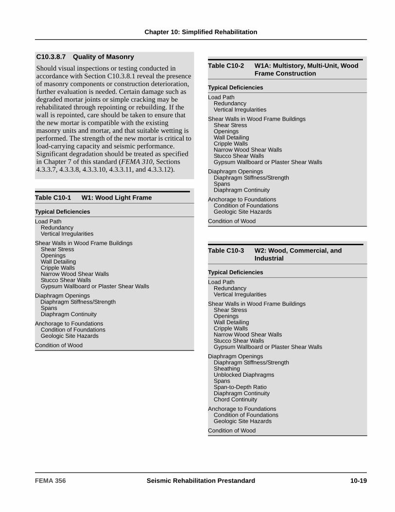
Chapter 10: Simplified Rehabilitation
C10.3.8.7 Quality of Masonry
Should visual inspections or testing conducted in accordance with Section C10.3.8.1 reveal the presence of masonry components or construction deterioration, further evaluation is needed. Certain damage such as degraded mortar joints or simple cracking may be rehabilitated through repointing or rebuilding. If the wall is repointed, care should be taken to ensure that the new mortar is compatible with the existing masonry units and mortar, and that suitable wetting is performed. The strength of the new mortar is critical to load-carrying capacity and seismic performance. Significant degradation should be treated as specified in Chapter 7 of this standard (FEMA 310, Sections 4.3.3.7, 4.3.3.8, 4.3.3.10, 4.3.3.11, and 4.3.3.12).
Table C10-1 W1: Wood Light Frame
Typical Deficiencies
Load PathRedundancyVertical Irregularities
Shear Walls in Wood Frame BuildingsShear StressOpeningsWall DetailingCripple WallsNarrow Wood Shear WallsStucco Shear WallsGypsum Wallboard or Plaster Shear Walls
Diaphragm OpeningsDiaphragm Stiffness/StrengthSpansDiaphragm Continuity
Anchorage to FoundationsCondition of FoundationsGeologic Site Hazards
Condition of Wood
Table C10-2 W1A: Multistory, Multi-Unit, Wood Frame Construction
Typical Deficiencies
Load PathRedundancyVertical Irregularities
Shear Walls in Wood Frame BuildingsShear StressOpeningsWall DetailingCripple WallsNarrow Wood Shear WallsStucco Shear WallsGypsum Wallboard or Plaster Shear Walls
Diaphragm OpeningsDiaphragm Stiffness/StrengthSpansDiaphragm Continuity
Anchorage to FoundationsCondition of FoundationsGeologic Site Hazards
Condition of Wood
Table C10-3 W2: Wood, Commercial, and Industrial
Typical Deficiencies
Load PathRedundancyVertical Irregularities
Shear Walls in Wood Frame BuildingsShear StressOpeningsWall DetailingCripple WallsNarrow Wood Shear WallsStucco Shear WallsGypsum Wallboard or Plaster Shear Walls
Diaphragm OpeningsDiaphragm Stiffness/StrengthSheathingUnblocked DiaphragmsSpansSpan-to-Depth RatioDiaphragm ContinuityChord Continuity
Anchorage to FoundationsCondition of FoundationsGeologic Site Hazards
Condition of Wood
FEMA 356 Seismic Rehabilitation Prestandard 10-19
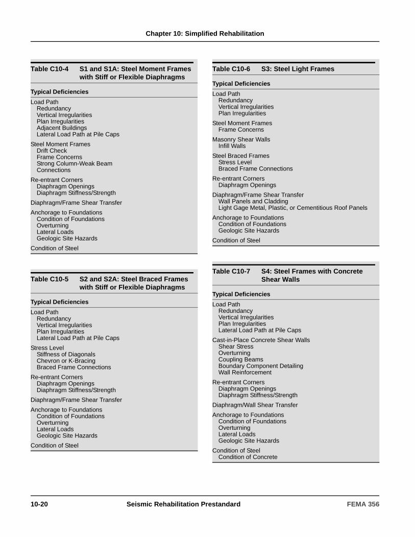
Chapter 10: Simplified Rehabilitation
Table C10-4 S1 and S1A: Steel Moment Frames with Stiff or Flexible Diaphragms
Typical Deficiencies
Load PathRedundancyVertical IrregularitiesPlan IrregularitiesAdjacent BuildingsLateral Load Path at Pile Caps
Steel Moment FramesDrift CheckFrame ConcernsStrong Column-Weak BeamConnections
Re-entrant CornersDiaphragm OpeningsDiaphragm Stiffness/Strength
Diaphragm/Frame Shear Transfer
Anchorage to FoundationsCondition of FoundationsOverturningLateral LoadsGeologic Site Hazards
Condition of Steel
Table C10-5 S2 and S2A: Steel Braced Frames with Stiff or Flexible Diaphragms
Typical Deficiencies
Load PathRedundancyVertical IrregularitiesPlan IrregularitiesLateral Load Path at Pile Caps
Stress LevelStiffness of DiagonalsChevron or K-BracingBraced Frame Connections
Re-entrant CornersDiaphragm OpeningsDiaphragm Stiffness/Strength
Diaphragm/Frame Shear Transfer
Anchorage to FoundationsCondition of FoundationsOverturningLateral LoadsGeologic Site Hazards
Condition of Steel
Table C10-6 S3: Steel Light Frames
Typical Deficiencies
Load PathRedundancyVertical IrregularitiesPlan Irregularities
Steel Moment FramesFrame Concerns
Masonry Shear WallsInfill Walls
Steel Braced FramesStress LevelBraced Frame Connections
Re-entrant CornersDiaphragm Openings
Diaphragm/Frame Shear TransferWall Panels and CladdingLight Gage Metal, Plastic, or Cementitious Roof Panels
Anchorage to FoundationsCondition of FoundationsGeologic Site Hazards
Condition of Steel
Table C10-7 S4: Steel Frames with Concrete Shear Walls
Typical Deficiencies
Load PathRedundancyVertical IrregularitiesPlan IrregularitiesLateral Load Path at Pile Caps
Cast-in-Place Concrete Shear WallsShear StressOverturningCoupling BeamsBoundary Component DetailingWall Reinforcement
Re-entrant CornersDiaphragm OpeningsDiaphragm Stiffness/Strength
Diaphragm/Wall Shear Transfer
Anchorage to FoundationsCondition of FoundationsOverturningLateral LoadsGeologic Site Hazards
Condition of SteelCondition of Concrete
10-20 Seismic Rehabilitation Prestandard FEMA 356
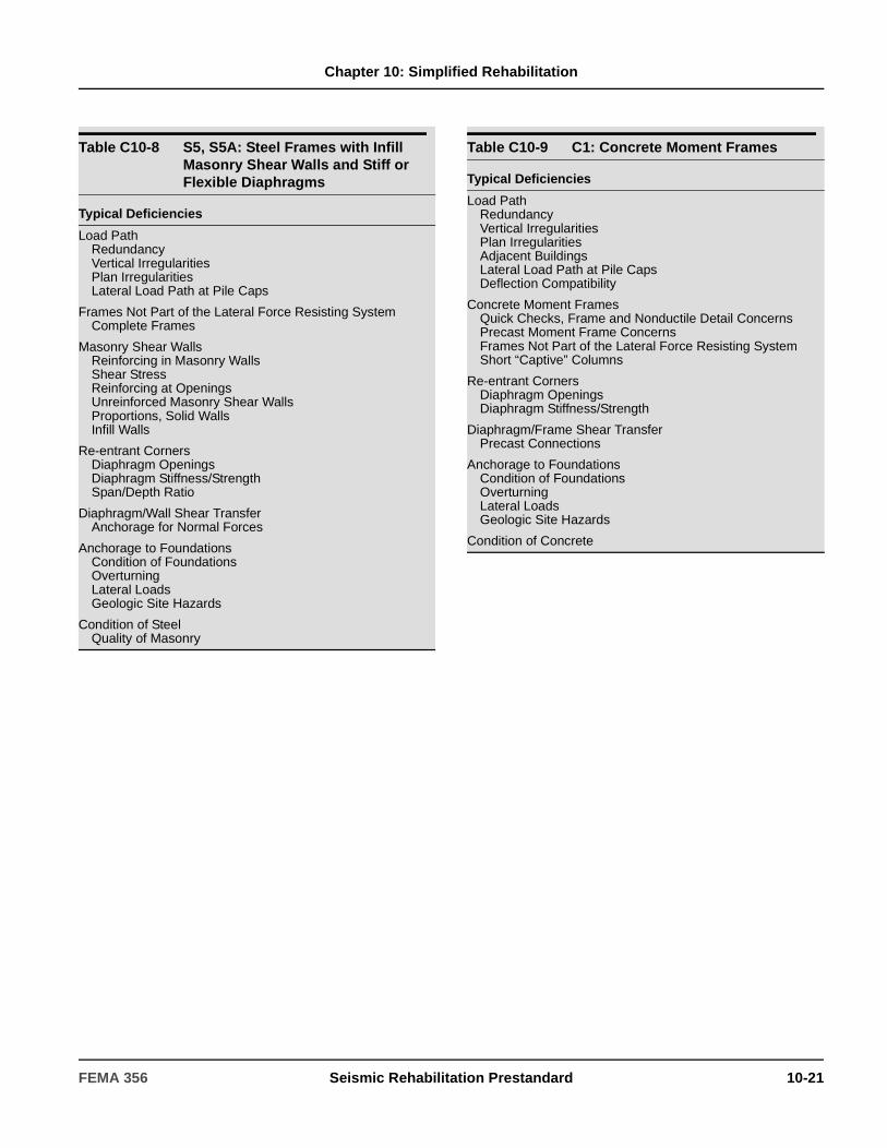
Chapter 10: Simplified Rehabilitation
Table C10-8 S5, S5A: Steel Frames with Infill Masonry Shear Walls and Stiff or Flexible Diaphragms
Typical Deficiencies
Load PathRedundancyVertical IrregularitiesPlan IrregularitiesLateral Load Path at Pile Caps
Frames Not Part of the Lateral Force Resisting SystemComplete Frames
Masonry Shear WallsReinforcing in Masonry WallsShear StressReinforcing at OpeningsUnreinforced Masonry Shear WallsProportions, Solid WallsInfill Walls
Re-entrant CornersDiaphragm OpeningsDiaphragm Stiffness/StrengthSpan/Depth Ratio
Diaphragm/Wall Shear TransferAnchorage for Normal Forces
Anchorage to FoundationsCondition of FoundationsOverturningLateral LoadsGeologic Site Hazards
Condition of SteelQuality of Masonry
Table C10-9 C1: Concrete Moment Frames
Typical Deficiencies
Load PathRedundancyVertical IrregularitiesPlan IrregularitiesAdjacent BuildingsLateral Load Path at Pile CapsDeflection Compatibility
Concrete Moment FramesQuick Checks, Frame and Nonductile Detail ConcernsPrecast Moment Frame ConcernsFrames Not Part of the Lateral Force Resisting SystemShort “Captive” Columns
Re-entrant CornersDiaphragm OpeningsDiaphragm Stiffness/Strength
Diaphragm/Frame Shear TransferPrecast Connections
Anchorage to FoundationsCondition of FoundationsOverturningLateral LoadsGeologic Site Hazards
Condition of Concrete
FEMA 356 Seismic Rehabilitation Prestandard 10-21
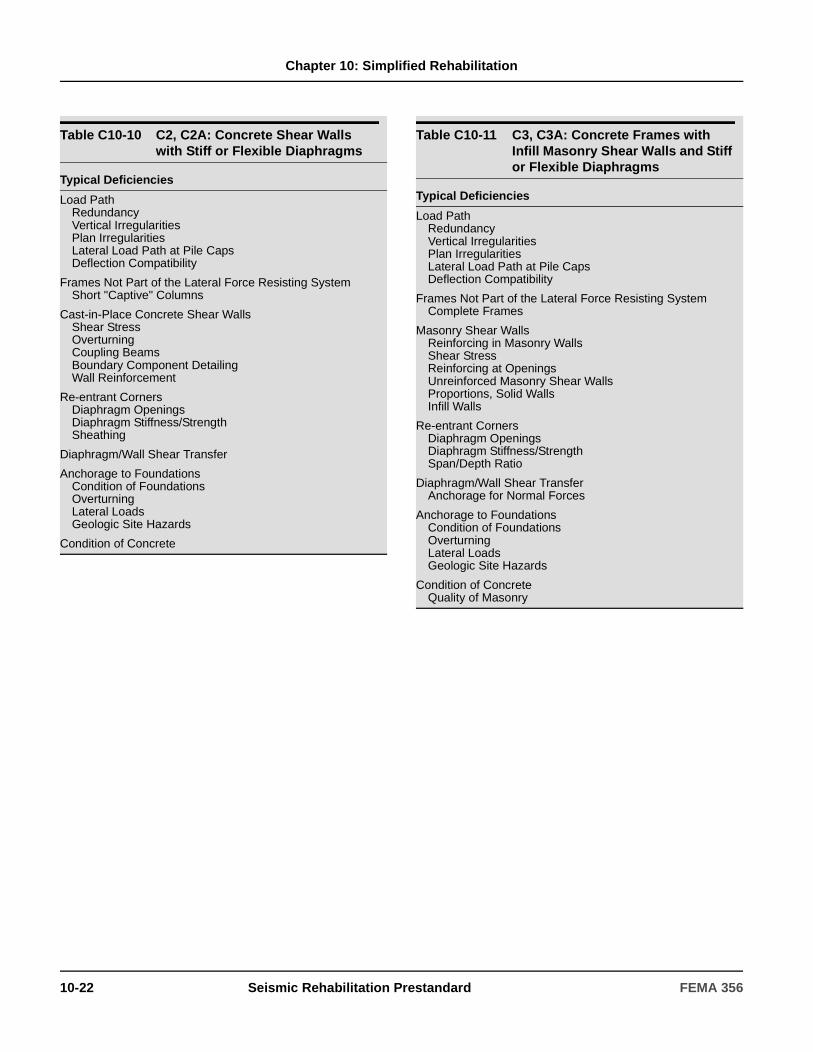
Chapter 10: Simplified Rehabilitation
Table C10-10 C2, C2A: Concrete Shear Walls with Stiff or Flexible Diaphragms
Typical Deficiencies
Load PathRedundancyVertical IrregularitiesPlan IrregularitiesLateral Load Path at Pile CapsDeflection Compatibility
Frames Not Part of the Lateral Force Resisting SystemShort "Captive" Columns
Cast-in-Place Concrete Shear WallsShear StressOverturningCoupling BeamsBoundary Component DetailingWall Reinforcement
Re-entrant CornersDiaphragm OpeningsDiaphragm Stiffness/StrengthSheathing
Diaphragm/Wall Shear Transfer
Anchorage to FoundationsCondition of FoundationsOverturningLateral LoadsGeologic Site Hazards
Condition of Concrete
Table C10-11 C3, C3A: Concrete Frames with Infill Masonry Shear Walls and Stiff or Flexible Diaphragms
Typical Deficiencies
Load PathRedundancyVertical IrregularitiesPlan IrregularitiesLateral Load Path at Pile CapsDeflection Compatibility
Frames Not Part of the Lateral Force Resisting SystemComplete Frames
Masonry Shear WallsReinforcing in Masonry WallsShear StressReinforcing at OpeningsUnreinforced Masonry Shear WallsProportions, Solid WallsInfill Walls
Re-entrant CornersDiaphragm OpeningsDiaphragm Stiffness/StrengthSpan/Depth Ratio
Diaphragm/Wall Shear TransferAnchorage for Normal Forces
Anchorage to FoundationsCondition of FoundationsOverturningLateral LoadsGeologic Site Hazards
Condition of ConcreteQuality of Masonry
10-22 Seismic Rehabilitation Prestandard FEMA 356
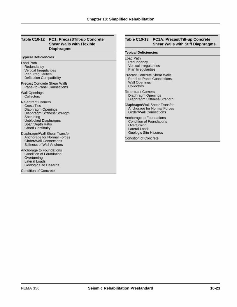
Chapter 10: Simplified Rehabilitation
Table C10-12 PC1: Precast/Tilt-up Concrete Shear Walls with Flexible Diaphragms
Typical Deficiencies
Load PathRedundancyVertical IrregularitiesPlan IrregularitiesDeflection Compatibility
Precast Concrete Shear WallsPanel-to-Panel Connections
Wall OpeningsCollectors
Re-entrant CornersCross TiesDiaphragm OpeningsDiaphragm Stiffness/StrengthSheathingUnblocked DiaphragmsSpan/Depth RatioChord Continuity
Diaphragm/Wall Shear TransferAnchorage for Normal ForcesGirder/Wall ConnectionsStiffness of Wall Anchors
Anchorage to FoundationsCondition of FoundationOverturningLateral LoadsGeologic Site Hazards
Condition of Concrete
Table C10-13 PC1A: Precast/Tilt-up Concrete Shear Walls with Stiff Diaphragms
Typical Deficiencies
Load PathRedundancyVertical IrregularitiesPlan Irregularities
Precast Concrete Shear WallsPanel-to-Panel ConnectionsWall OpeningsCollectors
Re-entrant CornersDiaphragm Openings Diaphragm Stiffness/Strength
Diaphragm/Wall Shear TransferAnchorage for Normal ForcesGirder/Wall Connections
Anchorage to FoundationsCondition of FoundationsOverturningLateral LoadsGeologic Site Hazards
Condition of Concrete
FEMA 356 Seismic Rehabilitation Prestandard 10-23
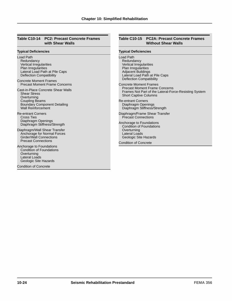
Chapter 10: Simplified Rehabilitation
Table C10-14 PC2: Precast Concrete Frames with Shear Walls
Typical Deficiencies
Load PathRedundancyVertical IrregularitiesPlan IrregularitiesLateral Load Path at Pile CapsDeflection Compatibility
Concrete Moment FramesPrecast Moment Frame Concerns
Cast-in-Place Concrete Shear WallsShear StressOverturningCoupling BeamsBoundary Component DetailingWall Reinforcement
Re-entrant CornersCross TiesDiaphragm OpeningsDiaphragm Stiffness/Strength
Diaphragm/Wall Shear TransferAnchorage for Normal ForcesGirder/Wall ConnectionsPrecast Connections
Anchorage to FoundationsCondition of FoundationsOverturningLateral LoadsGeologic Site Hazards
Condition of Concrete
Table C10-15 PC2A: Precast Concrete Frames Without Shear Walls
Typical Deficiencies
Load PathRedundancyVertical IrregularitiesPlan IrregularitiesAdjacent BuildingsLateral Load Path at Pile CapsDeflection Compatibility
Concrete Moment FramesPrecast Moment Frame ConcernsFrames Not Part of the Lateral-Force-Resisting SystemShort Captive Columns
Re-entrant CornersDiaphragm OpeningsDiaphragm Stiffness/Strength
Diaphragm/Frame Shear TransferPrecast Connections
Anchorage to FoundationsCondition of FoundationsOverturningLateral LoadsGeologic Site Hazards
Condition of Concrete
10-24 Seismic Rehabilitation Prestandard FEMA 356
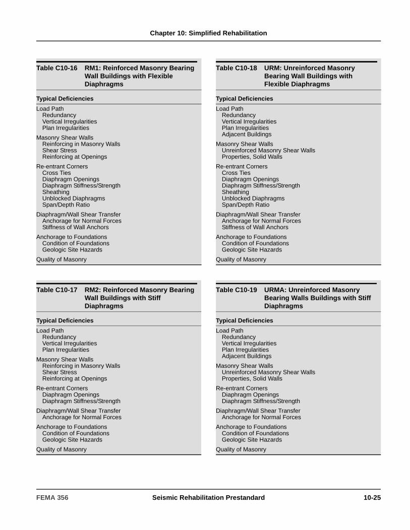
Chapter 10: Simplified Rehabilitation
Table C10-16 RM1: Reinforced Masonry Bearing Wall Buildings with Flexible Diaphragms
Typical Deficiencies
Load PathRedundancyVertical IrregularitiesPlan Irregularities
Masonry Shear WallsReinforcing in Masonry WallsShear StressReinforcing at Openings
Re-entrant CornersCross TiesDiaphragm OpeningsDiaphragm Stiffness/StrengthSheathingUnblocked DiaphragmsSpan/Depth Ratio
Diaphragm/Wall Shear TransferAnchorage for Normal ForcesStiffness of Wall Anchors
Anchorage to FoundationsCondition of FoundationsGeologic Site Hazards
Quality of Masonry
Table C10-17 RM2: Reinforced Masonry Bearing Wall Buildings with Stiff Diaphragms
Typical Deficiencies
Load PathRedundancyVertical IrregularitiesPlan Irregularities
Masonry Shear WallsReinforcing in Masonry WallsShear StressReinforcing at Openings
Re-entrant CornersDiaphragm OpeningsDiaphragm Stiffness/Strength
Diaphragm/Wall Shear TransferAnchorage for Normal Forces
Anchorage to FoundationsCondition of FoundationsGeologic Site Hazards
Quality of Masonry
Table C10-18 URM: Unreinforced Masonry Bearing Wall Buildings with Flexible Diaphragms
Typical Deficiencies
Load PathRedundancyVertical IrregularitiesPlan IrregularitiesAdjacent Buildings
Masonry Shear WallsUnreinforced Masonry Shear WallsProperties, Solid Walls
Re-entrant CornersCross TiesDiaphragm OpeningsDiaphragm Stiffness/StrengthSheathingUnblocked DiaphragmsSpan/Depth Ratio
Diaphragm/Wall Shear TransferAnchorage for Normal ForcesStiffness of Wall Anchors
Anchorage to FoundationsCondition of FoundationsGeologic Site Hazards
Quality of Masonry
Table C10-19 URMA: Unreinforced Masonry Bearing Walls Buildings with Stiff Diaphragms
Typical Deficiencies
Load PathRedundancyVertical IrregularitiesPlan IrregularitiesAdjacent Buildings
Masonry Shear WallsUnreinforced Masonry Shear WallsProperties, Solid Walls
Re-entrant CornersDiaphragm OpeningsDiaphragm Stiffness/Strength
Diaphragm/Wall Shear TransferAnchorage for Normal Forces
Anchorage to FoundationsCondition of FoundationsGeologic Site Hazards
Quality of Masonry
FEMA 356 Seismic Rehabilitation Prestandard 10-25
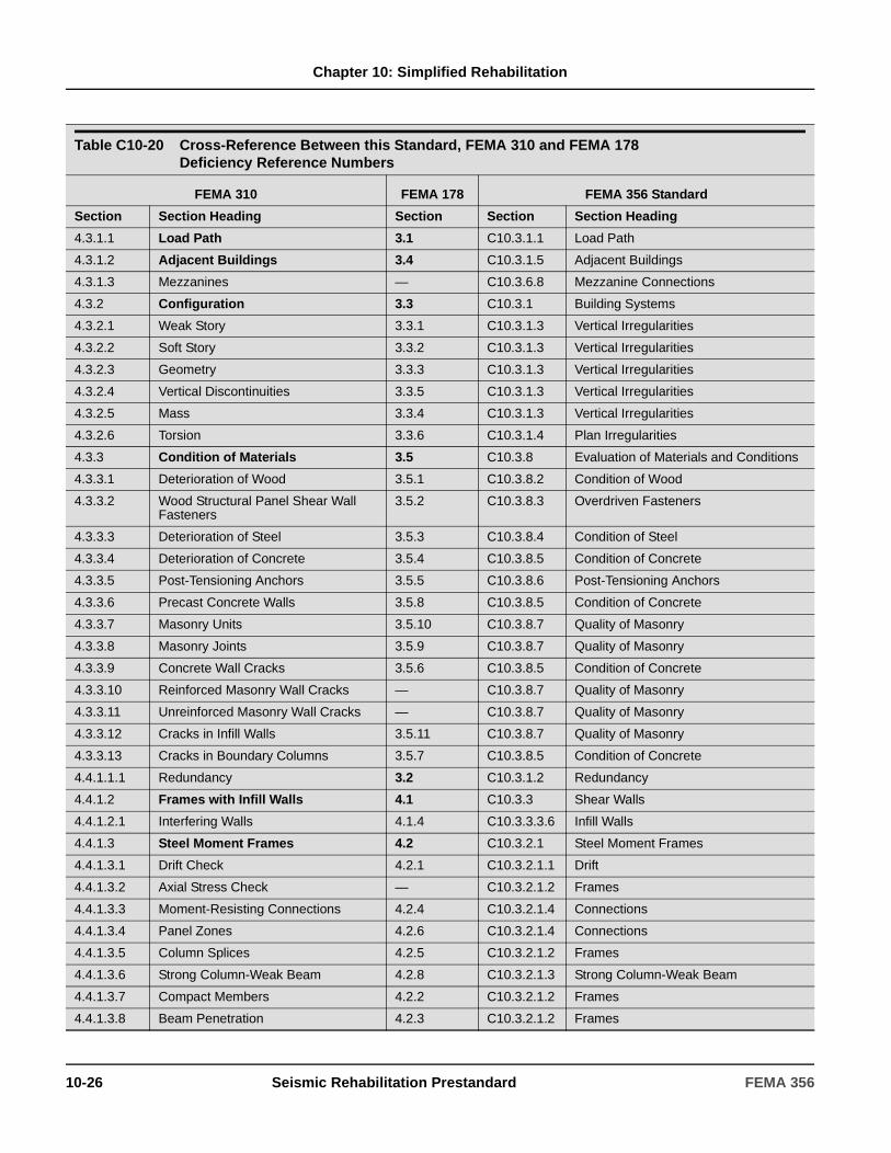
Chapter 10: Simplified Rehabilitation
Table C10-20 Cross-Reference Between this Standard, FEMA 310 and FEMA 178 Deficiency Reference Numbers
FEMA 310 FEMA 178 FEMA 356 Standard
Section Section Heading Section Section Section Heading
4.3.1.1 Load Path 3.1 C10.3.1.1 Load Path
4.3.1.2 Adjacent Buildings 3.4 C10.3.1.5 Adjacent Buildings
4.3.1.3 Mezzanines — C10.3.6.8 Mezzanine Connections
4.3.2 Configuration 3.3 C10.3.1 Building Systems
4.3.2.1 Weak Story 3.3.1 C10.3.1.3 Vertical Irregularities
4.3.2.2 Soft Story 3.3.2 C10.3.1.3 Vertical Irregularities
4.3.2.3 Geometry 3.3.3 C10.3.1.3 Vertical Irregularities
4.3.2.4 Vertical Discontinuities 3.3.5 C10.3.1.3 Vertical Irregularities
4.3.2.5 Mass 3.3.4 C10.3.1.3 Vertical Irregularities
4.3.2.6 Torsion 3.3.6 C10.3.1.4 Plan Irregularities
4.3.3 Condition of Materials 3.5 C10.3.8 Evaluation of Materials and Conditions
4.3.3.1 Deterioration of Wood 3.5.1 C10.3.8.2 Condition of Wood
4.3.3.2 Wood Structural Panel Shear Wall Fasteners
3.5.2 C10.3.8.3 Overdriven Fasteners
4.3.3.3 Deterioration of Steel 3.5.3 C10.3.8.4 Condition of Steel
4.3.3.4 Deterioration of Concrete 3.5.4 C10.3.8.5 Condition of Concrete
4.3.3.5 Post-Tensioning Anchors 3.5.5 C10.3.8.6 Post-Tensioning Anchors
4.3.3.6 Precast Concrete Walls 3.5.8 C10.3.8.5 Condition of Concrete
4.3.3.7 Masonry Units 3.5.10 C10.3.8.7 Quality of Masonry
4.3.3.8 Masonry Joints 3.5.9 C10.3.8.7 Quality of Masonry
4.3.3.9 Concrete Wall Cracks 3.5.6 C10.3.8.5 Condition of Concrete
4.3.3.10 Reinforced Masonry Wall Cracks — C10.3.8.7 Quality of Masonry
4.3.3.11 Unreinforced Masonry Wall Cracks — C10.3.8.7 Quality of Masonry
4.3.3.12 Cracks in Infill Walls 3.5.11 C10.3.8.7 Quality of Masonry
4.3.3.13 Cracks in Boundary Columns 3.5.7 C10.3.8.5 Condition of Concrete
4.4.1.1.1 Redundancy 3.2 C10.3.1.2 Redundancy
4.4.1.2 Frames with Infill Walls 4.1 C10.3.3 Shear Walls
4.4.1.2.1 Interfering Walls 4.1.4 C10.3.3.3.6 Infill Walls
4.4.1.3 Steel Moment Frames 4.2 C10.3.2.1 Steel Moment Frames
4.4.1.3.1 Drift Check 4.2.1 C10.3.2.1.1 Drift
4.4.1.3.2 Axial Stress Check — C10.3.2.1.2 Frames
4.4.1.3.3 Moment-Resisting Connections 4.2.4 C10.3.2.1.4 Connections
4.4.1.3.4 Panel Zones 4.2.6 C10.3.2.1.4 Connections
4.4.1.3.5 Column Splices 4.2.5 C10.3.2.1.2 Frames
4.4.1.3.6 Strong Column-Weak Beam 4.2.8 C10.3.2.1.3 Strong Column-Weak Beam
4.4.1.3.7 Compact Members 4.2.2 C10.3.2.1.2 Frames
4.4.1.3.8 Beam Penetration 4.2.3 C10.3.2.1.2 Frames
10-26 Seismic Rehabilitation Prestandard FEMA 356
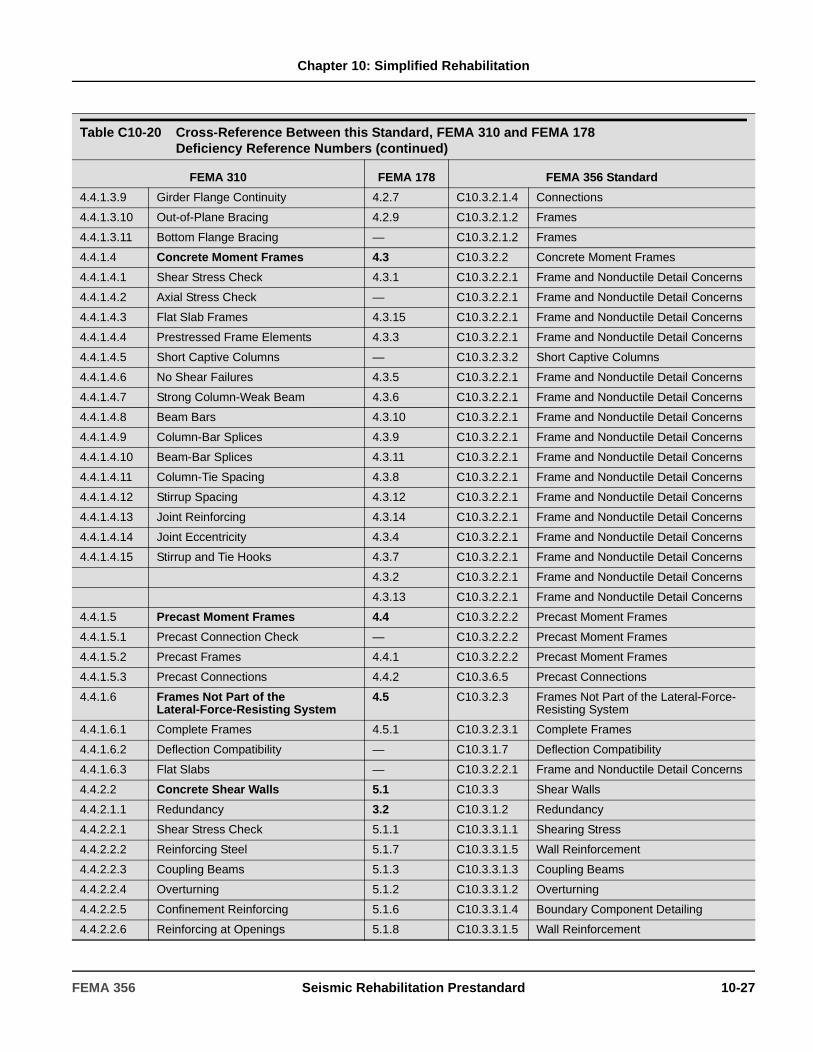
Chapter 10: Simplified Rehabilitation
4.4.1.3.9 Girder Flange Continuity 4.2.7 C10.3.2.1.4 Connections
4.4.1.3.10 Out-of-Plane Bracing 4.2.9 C10.3.2.1.2 Frames
4.4.1.3.11 Bottom Flange Bracing — C10.3.2.1.2 Frames
4.4.1.4 Concrete Moment Frames 4.3 C10.3.2.2 Concrete Moment Frames
4.4.1.4.1 Shear Stress Check 4.3.1 C10.3.2.2.1 Frame and Nonductile Detail Concerns
4.4.1.4.2 Axial Stress Check — C10.3.2.2.1 Frame and Nonductile Detail Concerns
4.4.1.4.3 Flat Slab Frames 4.3.15 C10.3.2.2.1 Frame and Nonductile Detail Concerns
4.4.1.4.4 Prestressed Frame Elements 4.3.3 C10.3.2.2.1 Frame and Nonductile Detail Concerns
4.4.1.4.5 Short Captive Columns — C10.3.2.3.2 Short Captive Columns
4.4.1.4.6 No Shear Failures 4.3.5 C10.3.2.2.1 Frame and Nonductile Detail Concerns
4.4.1.4.7 Strong Column-Weak Beam 4.3.6 C10.3.2.2.1 Frame and Nonductile Detail Concerns
4.4.1.4.8 Beam Bars 4.3.10 C10.3.2.2.1 Frame and Nonductile Detail Concerns
4.4.1.4.9 Column-Bar Splices 4.3.9 C10.3.2.2.1 Frame and Nonductile Detail Concerns
4.4.1.4.10 Beam-Bar Splices 4.3.11 C10.3.2.2.1 Frame and Nonductile Detail Concerns
4.4.1.4.11 Column-Tie Spacing 4.3.8 C10.3.2.2.1 Frame and Nonductile Detail Concerns
4.4.1.4.12 Stirrup Spacing 4.3.12 C10.3.2.2.1 Frame and Nonductile Detail Concerns
4.4.1.4.13 Joint Reinforcing 4.3.14 C10.3.2.2.1 Frame and Nonductile Detail Concerns
4.4.1.4.14 Joint Eccentricity 4.3.4 C10.3.2.2.1 Frame and Nonductile Detail Concerns
4.4.1.4.15 Stirrup and Tie Hooks 4.3.7 C10.3.2.2.1 Frame and Nonductile Detail Concerns
4.3.2 C10.3.2.2.1 Frame and Nonductile Detail Concerns
4.3.13 C10.3.2.2.1 Frame and Nonductile Detail Concerns
4.4.1.5 Precast Moment Frames 4.4 C10.3.2.2.2 Precast Moment Frames
4.4.1.5.1 Precast Connection Check — C10.3.2.2.2 Precast Moment Frames
4.4.1.5.2 Precast Frames 4.4.1 C10.3.2.2.2 Precast Moment Frames
4.4.1.5.3 Precast Connections 4.4.2 C10.3.6.5 Precast Connections
4.4.1.6 Frames Not Part of the Lateral-Force-Resisting System
4.5 C10.3.2.3 Frames Not Part of the Lateral-Force-Resisting System
4.4.1.6.1 Complete Frames 4.5.1 C10.3.2.3.1 Complete Frames
4.4.1.6.2 Deflection Compatibility — C10.3.1.7 Deflection Compatibility
4.4.1.6.3 Flat Slabs — C10.3.2.2.1 Frame and Nonductile Detail Concerns
4.4.2.2 Concrete Shear Walls 5.1 C10.3.3 Shear Walls
4.4.2.1.1 Redundancy 3.2 C10.3.1.2 Redundancy
4.4.2.2.1 Shear Stress Check 5.1.1 C10.3.3.1.1 Shearing Stress
4.4.2.2.2 Reinforcing Steel 5.1.7 C10.3.3.1.5 Wall Reinforcement
4.4.2.2.3 Coupling Beams 5.1.3 C10.3.3.1.3 Coupling Beams
4.4.2.2.4 Overturning 5.1.2 C10.3.3.1.2 Overturning
4.4.2.2.5 Confinement Reinforcing 5.1.6 C10.3.3.1.4 Boundary Component Detailing
4.4.2.2.6 Reinforcing at Openings 5.1.8 C10.3.3.1.5 Wall Reinforcement
Table C10-20 Cross-Reference Between this Standard, FEMA 310 and FEMA 178 Deficiency Reference Numbers (continued)
FEMA 310 FEMA 178 FEMA 356 Standard
FEMA 356 Seismic Rehabilitation Prestandard 10-27

Chapter 10: Simplified Rehabilitation
4.4.2.2.7 Wall Thickness — C10.3.3.1.1 Shearing Stress
4.4.2.2.8 Wall Connections 5.1.5 C10.3.3.1.4 Boundary Component Detailing
4.4.2.2.9 Column Splices 5.1.4 C10.3.3.1.4 Boundary Component Detailing
4.4.2.3 Precast Concrete Shear Walls 5.2 C10.3.3.2 Precast Concrete Shear Walls
4.4.2.3.1 Shear Stress Check — C10.3.3.1.1 Shearing Stress
4.4.2.3.2 Reinforcing Steel — C10.3.3.1.5 Wall Reinforcement
4.4.2.3.3 Wall Openings 5.2.2 C10.3.3.2.2 Wall Openings
4.4.2.3.4 Corner Openings 5.2.3 C10.3.3.2.3 Collectors
4.4.2.3.5 Panel-to-Panel Connections 5.2.1 C10.3.3.2.1 Panel-to-Panel Connections
4.4.2.3.6 Wall Thickness — C10.3.3.1.1 Shearing Stress
4.4.2.4 Reinforced Masonry Shear Walls 5.3 C10.3.3.3 Masonry Shear Walls
4.4.2.4.1 Shear Stress Check 5.3.1 C10.3.3.3.2 Shearing Stress
4.4.2.4.2 Reinforcing Steel 5.3.2 C10.3.3.3.1 Reinforcing in Masonry Walls
4.4.2.4.3 Reinforcing at Openings 5.3.3 C10.3.3.3.3 Reinforcing at Openings
4.4.2.4.4 Proportions — C10.3.3.3.5 Proportions of Solid Walls
4.4.2.5 Unreinforced Masonry Shear Walls 5.4 C10.3.3.3.4 Unreinforced Masonry Shear Walls
4.4.2.5.1 Shear Stress Check 5.4.1 C10.3.3.3.4 Unreinforced Masonry Shear Walls
4.4.2.5.2 Proportions — C10.3.3.3.5 Proportions of Solid Walls
4.4.2.5.3 Masonry Lay-up 5.4.2 C10.3.3.3.4 Unreinforced Masonry Shear Walls
4.4.2.6 Infill Walls in Frames 5.5 C10.3.3.3.6 Infill Walls
4.4.2.6.1 Wall Connections 5.5.4 C10.3.3.3.6 Infill Walls
4.4.2.6.2 Proportions 5.5.1 C10.3.3.3.5 Proportions of Solid Walls
4.4.2.6.3 Solid Walls 5.5.2 C10.3.3.3.5 Proportions of Solid Walls
4.4.2.6.4 Infill Walls 5.5.3 C10.3.3.3.6 Infill Walls
4.4.2.7 Walls in Wood Frame Buildings 5.6 C10.3.3.4 Shear Walls in Wood Frame Buildings
4.4.2.7.1 Shear Stress Check 5.6.1 C10.3.3.4.1 Shear Stress
4.4.2.7.2 Stucco (Exterior Plaster) Shear Walls — C10.3.3.4.6 Stucco Shear Walls
4.4.2.7.3 Gypsum Wallboard or Plaster Shear Walls
— C10.3.3.4.7 Gypsum Wallboard or Plaster Shear Walls
4.4.2.7.4 Narrow Wood Shear Walls — C10.3.3.4.5 Narrow Wood Shear Walls
4.4.2.7.5 Walls Connected Through Floors — C10.3.3.4.3 Wall Detailing
4.4.2.7.6 Hillside Site — C10.3.3.4.4 Cripple Walls
4.4.2.7.7 Cripple Walls 5.6.4 C10.3.3.4.4 Cripple Walls
4.4.2.7.8 Openings 5.6.2 C10.3.3.4.2 Openings
4.4.2.7.9 Hold-Down Anchors 5.6.3 C10.3.3.4.3 Wall Detailing
Table C10-20 Cross-Reference Between this Standard, FEMA 310 and FEMA 178 Deficiency Reference Numbers (continued)
FEMA 310 FEMA 178 FEMA 356 Standard
10-28 Seismic Rehabilitation Prestandard FEMA 356
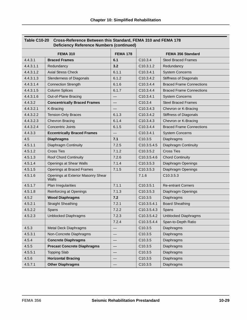
Chapter 10: Simplified Rehabilitation
4.4.3.1 Braced Frames 6.1 C10.3.4 Steel Braced Frames
4.4.3.1.1 Redundancy 3.2 C10.3.1.2 Redundancy
4.4.3.1.2 Axial Stress Check 6.1.1 C10.3.4.1 System Concerns
4.4.3.1.3 Slenderness of Diagonals 6.1.2 C10.3.4.2 Stiffness of Diagonals
4.4.3.1.4 Connection Strength 6.1.6 C10.3.4.4 Braced Frame Connections
4.4.3.1.5 Column Splices 6.1.7 C10.3.4.4 Braced Frame Connections
4.4.3.1.6 Out-of-Plane Bracing — C10.3.4.1 System Concerns
4.4.3.2 Concentrically Braced Frames — C10.3.4 Steel Braced Frames
4.4.3.2.1 K-Bracing — C10.3.4.3 Chevron or K-Bracing
4.4.3.2.2 Tension-Only Braces 6.1.3 C10.3.4.2 Stiffness of Diagonals
4.4.3.2.3 Chevron Bracing 6.1.4 C10.3.4.3 Chevron or K-Bracing
4.4.3.2.4 Concentric Joints 6.1.5 C10.3.4.4 Braced Frame Connections
4.4.3.3 Eccentrically Braced Frames — C10.3.4.1 System Concerns
4.5 Diaphragms 7.1 C10.3.5 Diaphragms
4.5.1.1 Diaphragm Continuity 7.2.5 C10.3.5.4.5 Diaphragm Continuity
4.5.1.2 Cross Ties 7.1.2 C10.3.5.2 Cross Ties
4.5.1.3 Roof Chord Continuity 7.2.6 C10.3.5.4.6 Chord Continuity
4.5.1.4 Openings at Shear Walls 7.1.4 C10.3.5.3 Diaphragm Openings
4.5.1.5 Openings at Braced Frames 7.1.5 C10.3.5.3 Diaphragm Openings
4.5.1.6 Openings at Exterior Masonry Shear Walls
7.1.6 C10.3.5.3
4.5.1.7 Plan Irregularities 7.1.1 C10.3.5.1 Re-entrant Corners
4.5.1.8 Reinforcing at Openings 7.1.3 C10.3.5.3 Diaphragm Openings
4.5.2 Wood Diaphragms 7.2 C10.3.5 Diaphragms
4.5.2.1 Straight Sheathing 7.2.1 C10.3.5.4.1 Board Sheathing
4.5.2.2 Spans 7.2.2 C10.3.5.4.3 Spans
4.5.2.3 Unblocked Diaphragms 7.2.3 C10.3.5.4.2 Unblocked Diaphragms
7.2.4 C10.3.5.4.4 Span-to-Depth Ratio
4.5.3 Metal Deck Diaphragms — C10.3.5 Diaphragms
4.5.3.1 Non-Concrete Diaphragms — C10.3.5 Diaphragms
4.5.4 Concrete Diaphragms — C10.3.5 Diaphragms
4.5.5 Precast Concrete Diaphragms — C10.3.5 Diaphragms
4.5.5.1 Topping Slab — C10.3.5 Diaphragms
4.5.6 Horizontal Bracing — C10.3.5 Diaphragms
4.5.7.1 Other Diaphragms — C10.3.5 Diaphragms
Table C10-20 Cross-Reference Between this Standard, FEMA 310 and FEMA 178 Deficiency Reference Numbers (continued)
FEMA 310 FEMA 178 FEMA 356 Standard
FEMA 356 Seismic Rehabilitation Prestandard 10-29

Chapter 10: Simplified Rehabilitation
4.6.1 Anchorage for Normal Forces 8.2 C10.3.6.3 Anchorage for Normal Forces
4.6.1.1 Wall Anchorage 8.2.2 C10.3.6.3 Anchorage for Normal Forces
4.6.1.2 Wood Ledgers 8.2.1 C10.3.6.3 Anchorage for Normal Forces
4.6.1.3 Anchor Spacing 8.2.4 C10.3.6.3 Anchorage for Normal Forces
4.6.1.4 Precast Panel Connections 8.2.5 C10.3.6.3 Anchorage for Normal Forces
4.6.1.5 Stiffness of Wall Anchors 8.2.3 C10.3.6.3 Anchorage for Normal Forces
4.6.2 Shear Transfer 8.3 C10.3.6 Connections
4.6.2.1 Transfer to Shear Walls 8.3.1 C10.3.6.1 Diaphragm/Wall Shear Transfer
4.6.2.2 Transfer to Steel Frames 8.3.2 C10.3.6.2 Diaphragm/Frame Shear Transfer
4.6.2.3 Topping Slab to Walls and Frames 8.3.3 C10.3.6.1 Diaphragm/Wall Shear Transfer
4.6.3 Vertical Components 8.4 C10.3.7.1 Anchorage to Foundations
4.6.3.1 Steel Columns 8.4.1 C10.3.7.1 Anchorage to Foundations
4.6.3.2 Concrete Columns 8.4.2 C10.3.7.1 Anchorage to Foundations
4.6.3.3 Wood Posts 8.4.3 C10.3.7.1 Anchorage to Foundations
4.6.3.4 Wood Sills 8.4.7 C10.3.7.1 Anchorage to Foundations
4.6.3.5 Foundation Dowels 8.4.4 C10.3.7.1 Anchorage to Foundations
4.6.3.6 Shear-Wall-Boundary Columns 8.4.5 C10.3.7.1 Anchorage to Foundations
4.6.3.7 Precast Wall Panels — C10.3.7.1 Anchorage to Foundations
4.6.3.8 Wall Panels 8.4.6 C10.3.7.1 Anchorage to Foundations
4.6.3.9 Wood Sill Bolts 8.4.7 C10.3.7.1 Anchorage to Foundations
4.6.3.10 Lateral Load Path at Pile Caps — C10.3.7.4 Lateral Loads
4.6.4 Interconnection of Elements 8.5 C10.3.6 Connections
4.6.4.1 Girder/Column Connection C10.3.6.4 Girder-Wall Connections
4.6.4.2 Girders 8.5.1 C10.3.6.4 Girder-Wall Connections
4.6.4.3 Corbel Bearing 8.5.2 C10.3.6.4 Girder-Wall Connections
4.6.4.4 Corbel Connections 8.5.3 C10.3.6.4 Girder-Wall Connections
4.6.5 Panel Connections — C10.3.6 Connections
4.6.5.1 Roof Panels 8.6.1 C10.3.6.7 Light Gage Metal, Plastic, or Cementitious Roof Panels
4.6.5.2 Wall Panels 8.6.2 C10.3.6.6 Wall Panels and Cladding
4.6.5.3 Roof Panel Connections — C10.3.6.7 Light Gage Metal, Plastic, or Cementitious Roof Panels
4.7.1 Geologic Site Hazards 9.3 C10.3.7 Foundations and Geologic Hazards
4.7.1.1 Liquefaction 9.3.1 C10.3.7.5 Geologic Site Hazards
4.7.1.2 Slope Failure 9.3.2 C10.3.7.5 Geologic Site Hazards
4.7.1.3 Surface Fault Rupture 9.3.3 C10.3.7.5 Geologic Site Hazards
Table C10-20 Cross-Reference Between this Standard, FEMA 310 and FEMA 178 Deficiency Reference Numbers (continued)
FEMA 310 FEMA 178 FEMA 356 Standard
10-30 Seismic Rehabilitation Prestandard FEMA 356

Chapter 10: Simplified Rehabilitation
4.7.2 Condition of Foundations 9.1 C10.3.7.2 Condition of Foundations
4.7.2.1 Foundation Performance 9.1.1 C10.3.7.2 Condition of Foundations
4.7.2.2 Deterioration 9.1.2 C10.3.7.2 Condition of Foundations
4.7.3 Capacity of Foundations 9.2 C10.3.7 Foundations and Geologic Hazards
4.7.3.1 Pole Foundations 9.2.4 C10.3.7.4 Lateral Loads
4.7.3.2 Overturning 9.2.1 C10.3.7.3 Overturning
4.7.3.3 Ties Between Foundation Elements 9.2.2 C10.3.7.4 Lateral Loads
4.7.3.4 Deep Foundations 9.2.3 C10.3.7.4 Lateral Loads
4.7.3.5 Sloping Sites 9.2.5 C10.3.7.4 Lateral Loads
Table C10-20 Cross-Reference Between this Standard, FEMA 310 and FEMA 178 Deficiency Reference Numbers (continued)
FEMA 310 FEMA 178 FEMA 356 Standard
FEMA 356 Seismic Rehabilitation Prestandard 10-31

Chapter 10: Simplified Rehabilitation
10-32 Seismic Rehabilitation Prestandard FEMA 356
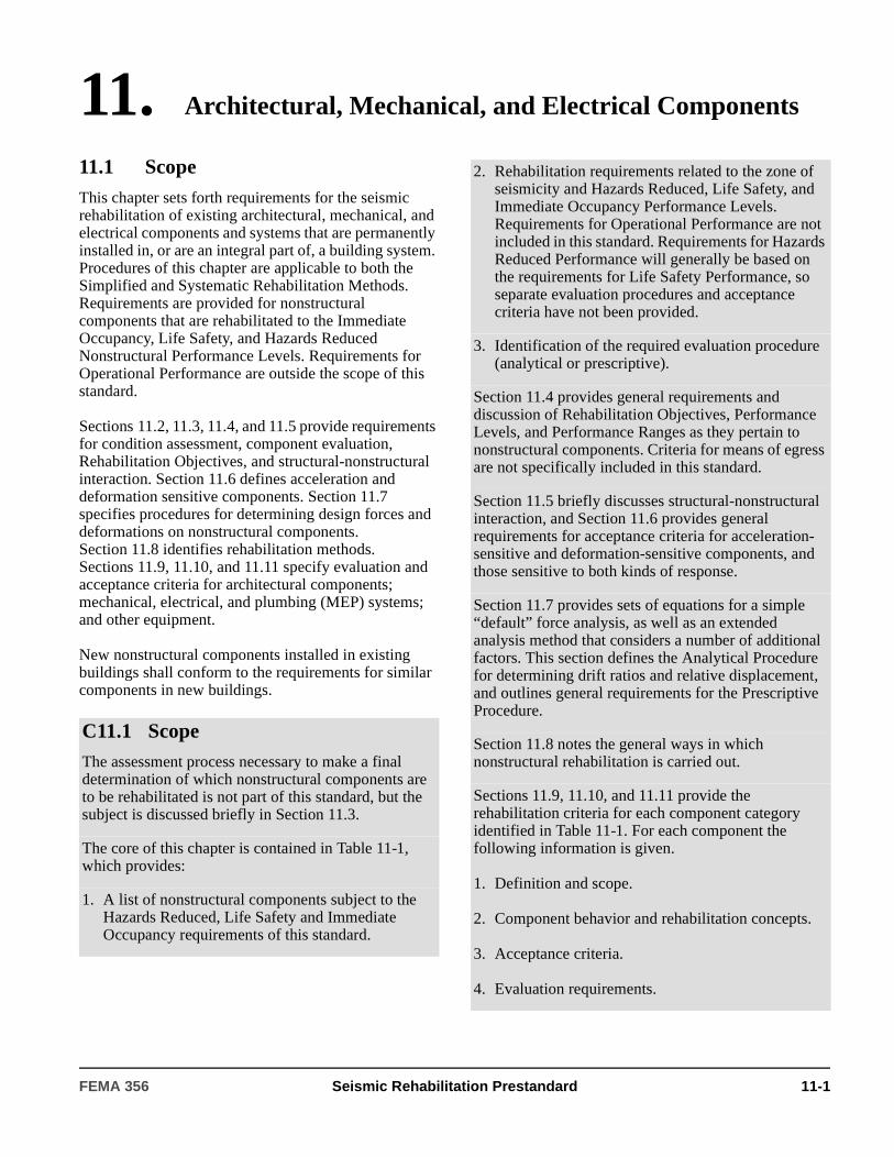
11. Architectural, Mechanical, and Electrical Components
11.1 ScopeThis chapter sets forth requirements for the seismic rehabilitation of existing architectural, mechanical, and electrical components and systems that are permanently installed in, or are an integral part of, a building system. Procedures of this chapter are applicable to both the Simplified and Systematic Rehabilitation Methods. Requirements are provided for nonstructural components that are rehabilitated to the Immediate Occupancy, Life Safety, and Hazards Reduced Nonstructural Performance Levels. Requirements for Operational Performance are outside the scope of this standard.
Sections 11.2, 11.3, 11.4, and 11.5 provide requirements for condition assessment, component evaluation, Rehabilitation Objectives, and structural-nonstructural interaction. Section 11.6 defines acceleration and deformation sensitive components. Section 11.7 specifies procedures for determining design forces and deformations on nonstructural components. Section 11.8 identifies rehabilitation methods. Sections 11.9, 11.10, and 11.11 specify evaluation and acceptance criteria for architectural components; mechanical, electrical, and plumbing (MEP) systems; and other equipment.
New nonstructural components installed in existing buildings shall conform to the requirements for similar components in new buildings.
C11.1 ScopeThe assessment process necessary to make a final determination of which nonstructural components are to be rehabilitated is not part of this standard, but the subject is discussed briefly in Section 11.3.
The core of this chapter is contained in Table 11-1, which provides:
1. A list of nonstructural components subject to the Hazards Reduced, Life Safety and Immediate Occupancy requirements of this standard.
2. Rehabilitation requirements related to the zone of seismicity and Hazards Reduced, Life Safety, and Immediate Occupancy Performance Levels. Requirements for Operational Performance are not included in this standard. Requirements for Hazards Reduced Performance will generally be based on the requirements for Life Safety Performance, so separate evaluation procedures and acceptance criteria have not been provided.
3. Identification of the required evaluation procedure (analytical or prescriptive).
Section 11.4 provides general requirements and discussion of Rehabilitation Objectives, Performance Levels, and Performance Ranges as they pertain to nonstructural components. Criteria for means of egress are not specifically included in this standard.
Section 11.5 briefly discusses structural-nonstructural interaction, and Section 11.6 provides general requirements for acceptance criteria for acceleration-sensitive and deformation-sensitive components, and those sensitive to both kinds of response.
Section 11.7 provides sets of equations for a simple “default” force analysis, as well as an extended analysis method that considers a number of additional factors. This section defines the Analytical Procedure for determining drift ratios and relative displacement, and outlines general requirements for the Prescriptive Procedure.
Section 11.8 notes the general ways in which nonstructural rehabilitation is carried out.
Sections 11.9, 11.10, and 11.11 provide the rehabilitation criteria for each component category identified in Table 11-1. For each component the following information is given.
1. Definition and scope.
2. Component behavior and rehabilitation concepts.
3. Acceptance criteria.
4. Evaluation requirements.
FEMA 356 Seismic Rehabilitation Prestandard 11-1

Chapter 11: Architectural, Mechanical, and
Electrical Components
11.2 ProcedureNonstructural components shall be rehabilitated by completing the following steps.
1. The rehabilitation objectives shall be established in accordance with Section 11.4, which includes selection of a Nonstructural Performance Level and earthquake hazard level. The zone of seismicity shall be determined in accordance with Section 1.6.3. A target Building Performance Level that includes Nonstructural Performance Not Considered need not comply with the provisions of this chapter.
2. A walk-through and condition assessment shall be performed in accordance with Sections 11.2.1 and 11.2.2.
3. Analysis and rehabilitation requirements for the selected Nonstructural Performance Level and appropriate zone of seismicity shall be determined for nonstructural components using Table 11-1. “Yes” indicates that rehabilitation shall be required if the component does not meet applicable acceptance criteria specified in Section 11.3.2.
4. Interaction between structural and nonstructural components shall be considered in accordance with Section 11.5.
5. The classification of each type of nonstructural component shall be determined in accordance with Section 11.6.
6. Evaluation shall be conducted in accordance with Section 11.7 using the procedure specified in Table 11-1. The acceptability of bracing elements and connections between nonstructural components and the structure shall be determined in accordance with Section 11.3.2.
7. Nonstructural components not meeting the requirements of the selected Nonstructural Performance Level shall be rehabilitated in accordance with Section 11.8.
11.2.1 Condition Assessment
A condition assessment of nonstructural components shall be performed as part of the nonstructural rehabilitation process. As a minimum, this assessment shall determine the following:
1. The presence and configuration of each type of nonstructural component and its attachment to the structure.
2. The physical condition of each type of nonstructural component and whether or not degradation is present.
3. The presence of nonstructural components that potentially influence overall building performance.
11.2.2 Sample Size
Direct visual inspection shall be performed on each type of nonstructural component in the building as follows:
1. If detailed drawings are available, at least one sample of each type of nonstructural component shall be observed. If no deviations from the drawings exist, the sample shall be considered representative of installed conditions. If deviations are observed, then at least 10% of all occurrences of the component shall be observed.
2. If detailed drawings are not available, at least three samples of each type of nonstructural component shall be observed. If no deviations among the three components are observed, the sample shall be considered representative of installed conditions. If deviations are observed, at least 20% of all occurrences of the component shall be observed.
C11.2 ProcedureWhen Hazards Reduced Performance is used, the engineer should consider the location of nonstructural components relative to areas of public occupancy. The owner and building official should be consulted to establish the areas of the building for which nonstructural hazards will be considered. Other nonstructural components, such as those designated by the owner also should be included in those that are evaluated.
11-2 Seismic Rehabilitation Prestandard FEMA 356

Chapter 11: Architectural, Mechanical, and
Electrical Components
Table 11-1 Nonstructural Components: Applicability of Hazards Reduced, Life Safety and Immediate Occupancy Requirements and Methods of Analysis
COMPONENT
Performance Level
Evaluation ProcedureIO
Seismicity
High & Moderate Seismicity
LowSeismicity
LS HR LS HR
ARCHITECTURAL (Section 11.9)1. Exterior Wall Elements
Adhered Veneer Yes Yes Yes15 No No F/D
Anchored Veneer Yes Yes Yes15 No No F/D
Glass Blocks Yes Yes Yes15 No No F/D
Prefabricated Panels Yes Yes Yes15 Yes Yes15 F/D
Glazed Exterior Wall Systems Yes Yes Yes15 Yes Yes15 F/D/PR
2. Partitions Heavy Yes Yes Yes15 No No F/D
Light Yes No No No No F/DGlazed Yes Yes Yes15 Yes Yes15 F/D/PR
3. Interior Veneers Stone, Including Marble Yes Yes18 Yes15 No No F/D
4. Ceilings Directly Applied to Structure Yes No13 No15 No No F
Dropped Furred Gypsum Board Yes No No No No F
Suspended Lath and Plaster Yes Yes Yes15 No No F
Suspended Integrated Ceiling Yes No11 No No11 No PR
5. Parapets and Appendages Yes Yes Yes15 Yes Yes F1
6. Canopies and Marquees Yes Yes Yes15 Yes Yes F
7. Chimneys and Stacks Yes Yes Yes15 No No F2
8. Stairs Yes Yes No Yes No *
MECHANICAL EQUIPMENT (Section 11.10)1. Mechanical Equipment
Boilers, Furnaces, Pumps, and Chillers Yes Yes No Yes No F
General Mfg. and Process Machinery Yes No3 No No No F
HVAC Equipment, Vibration-Isolated Yes No3 No No No F
HVAC Equipment, Non-Vibration-Isolated Yes No3 No No No F
HVAC Equipment, Mounted In-Line with Ductwork
Yes No3 No No No PR
2. Storage Vessels and Water Heaters Structurally Supported Vessels (Category 1) Yes No3 No No No Note4
Flat Bottom Vessels (Category 2) Yes No3 No No No Note5
3. Pressure Piping Yes Yes No No No Note5
4. Fire Suppression Piping Yes Yes No No No PR
FEMA 356 Seismic Rehabilitation Prestandard 11-3
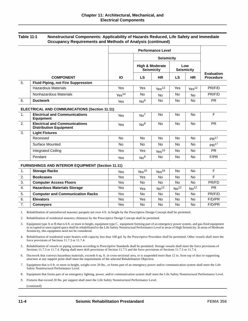
Chapter 11: Architectural, Mechanical, and
Electrical Components
5. Fluid Piping, not Fire Suppression Hazardous Materials Yes Yes Yes12 Yes Yes12 PR/F/D
Nonhazardous Materials Yes14 No No No No PR/F/D
6. Ductwork Yes No6 No No No PR
ELECTRICAL AND COMMUNICATIONS (Section 11.11)1. Electrical and Communications
Equipment Yes No7 No No No F
2. Electrical and Communications Distribution Equipment
Yes No8 No No No PR
3. Light Fixtures Recessed No No No No No PR17
Surface Mounted No No No No No PR17
Integrated Ceiling Yes Yes Yes15 No No PR
Pendant Yes No9 No No No F/PR
FURNISHINGS AND INTERIOR EQUIPMENT (Section 11.11)1. Storage Racks Yes Yes10 Yes16 No No F
2. Bookcases Yes Yes No No No F
3. Computer Access Floors Yes No No No No PR/FD4. Hazardous Materials Storage Yes Yes No12 No12 No12 PR
5. Computer and Communication Racks Yes No No No No PR/F/D
6. Elevators Yes Yes No No No F/D/PR7. Conveyors Yes No No No No F/D/PR
1. Rehabilitation of unreinforced masonry parapets not over 4 ft. in height by the Prescriptive Design Concept shall be permitted.
2. Rehabilitation of residential masonry chimneys by the Prescriptive Design Concept shall be permitted.
3. Equipment type A or B that is 6 ft. or more in height, equipment type C, equipment forming part of an emergency power system, and gas-fired equipment in occupied or unoccupied space shall be rehabilitated to the Life Safety Nonstructual Performance Level in areas of High Seismicity. In areas of Moderate Seismicity, this equipment need not be considered.
4. Rehabilitation of residential water heaters with capacity less than 100 gal. by the Prescriptive Procedure shall be permitted. Other vessels shall meet the force provisions of Sections 11.7.3 or 11.7.4.
5. Rehabilitation of vessels or piping systems according to Prescriptive Standards shall be permitted. Storage vessels shall meet the force provisions of Sections 11.7.3 or 11.7.4. Piping shall meet drift provisions of Section 11.7.5 and the force provisions of Sections 11.7.3 or 11.7.4.
6. Ductwork that conveys hazardous materials, exceeds 6 sq. ft. in cross-sectional area, or is suspended more than 12 in. from top of duct to supporting structure at any support point shall meet the requirements of the selected Rehabilitation Objective.
7. Equipment that is 6 ft. or more in height, weighs over 20 lbs., or forms part of an emergency power and/or communication system shall meet the Life Safety Nonstructural Performance Level.
8. Equipment that forms part of an emergency lighting, power, and/or communication system shall meet the Life Safety Nonstructural Performance Level.
9. Fixtures that exceed 20 lbs. per support shall meet the Life Safety Nonstructural Performance Level.
(continued)
Table 11-1 Nonstructural Components: Applicability of Hazards Reduced, Life Safety and Immediate Occupancy Requirements and Methods of Analysis (continued)
COMPONENT
Performance Level
Evaluation ProcedureIO
Seismicity
High & Moderate Seismicity
LowSeismicity
LS HR LS HR
11-4 Seismic Rehabilitation Prestandard FEMA 356
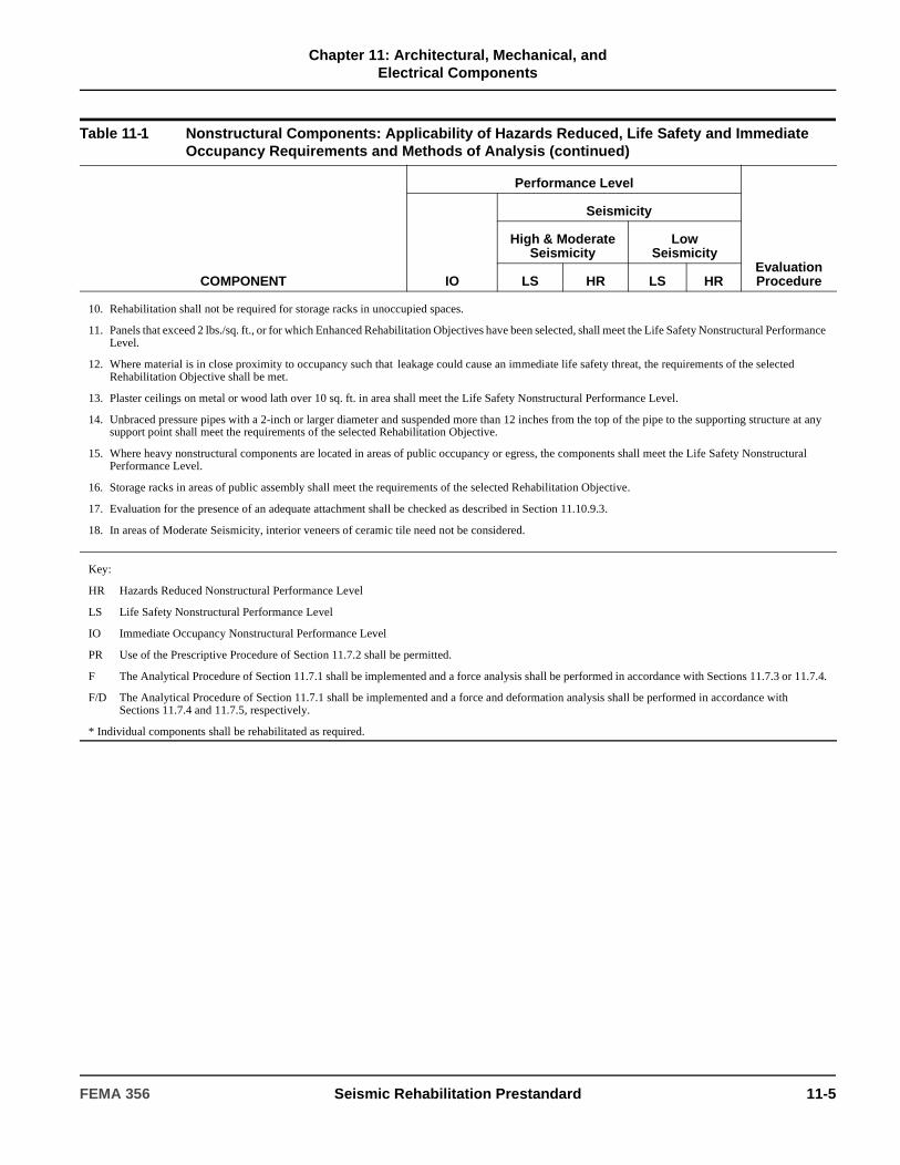
Chapter 11: Architectural, Mechanical, and
Electrical Components
10. Rehabilitation shall not be required for storage racks in unoccupied spaces.
11. Panels that exceed 2 lbs./sq. ft., or for which Enhanced Rehabilitation Objectives have been selected, shall meet the Life Safety Nonstructural Performance Level.
12. Where material is in close proximity to occupancy such that leakage could cause an immediate life safety threat, the requirements of the selected Rehabilitation Objective shall be met.
13. Plaster ceilings on metal or wood lath over 10 sq. ft. in area shall meet the Life Safety Nonstructural Performance Level.
14. Unbraced pressure pipes with a 2-inch or larger diameter and suspended more than 12 inches from the top of the pipe to the supporting structure at any support point shall meet the requirements of the selected Rehabilitation Objective.
15. Where heavy nonstructural components are located in areas of public occupancy or egress, the components shall meet the Life Safety Nonstructural Performance Level.
16. Storage racks in areas of public assembly shall meet the requirements of the selected Rehabilitation Objective.
17. Evaluation for the presence of an adequate attachment shall be checked as described in Section 11.10.9.3.
18. In areas of Moderate Seismicity, interior veneers of ceramic tile need not be considered.
Key:
HR Hazards Reduced Nonstructural Performance Level
LS Life Safety Nonstructural Performance Level
IO Immediate Occupancy Nonstructural Performance Level
PR Use of the Prescriptive Procedure of Section 11.7.2 shall be permitted.
F The Analytical Procedure of Section 11.7.1 shall be implemented and a force analysis shall be performed in accordance with Sections 11.7.3 or 11.7.4.
F/D The Analytical Procedure of Section 11.7.1 shall be implemented and a force and deformation analysis shall be performed in accordance with Sections 11.7.4 and 11.7.5, respectively.
* Individual components shall be rehabilitated as required.
Table 11-1 Nonstructural Components: Applicability of Hazards Reduced, Life Safety and Immediate Occupancy Requirements and Methods of Analysis (continued)
COMPONENT
Performance Level
Evaluation ProcedureIO
Seismicity
High & Moderate Seismicity
LowSeismicity
LS HR LS HR
FEMA 356 Seismic Rehabilitation Prestandard 11-5

Chapter 11: Architectural, Mechanical, and
Electrical Components
11.3 Historical and Component Evaluation Considerations
11.3.1 Historical Information
Available construction documents, equipment specification and data, and as-built information shall be obtained as specified in Section 2.2. Data on nonstructural components and equipment shall be collected to ascertain the year of manufacture or installation of nonstructural components to justify selection of rehabilitation approaches and techniques based on available historical information, prevailing codes, and assessment of existing condition.
C11.3.1 Historical Information
The architectural, mechanical, and electrical components and systems of a historic building may be historically significant, especially if they are original to the building, very old, or innovative. Historic buildings may also contain hazardous materials, such as lead pipes and asbestos, that may or may not pose a hazard depending on their location, condition, use or abandonment, containment, and/or disturbance during the rehabilitation.
C11.3.1.1 Background
Prior to the 1961 Uniform Building Code and the 1964 Alaska earthquake, architectural components and mechanical and electrical systems for buildings had typically been designed with little, if any, regard to stability when subjected to seismic forces. By the time of the 1971 San Fernando earthquake, it became clear that damage to nonstructural elements could result in serious casualties, severe building functional impairment, and major economic losses, even when structural damage was not significant (Lagorio, 1990). This historical perspective presents the background for the development of building code provisions, together with a historical review of professional and construction practices related to the seismic design and construction of nonstructural components.
Since the 1964 Alaska earthquake, the poor performance of nonstructural elements has been identified in earthquake reconnaissance reports. Subsequent editions of the Uniform Building Code (ICBO, 1994), as well as California and Federal codes and laws have increased both the scope and strictness of nonstructural seismic provisions in an attempt to achieve better performance. Table C11-1 and Table C11-2 provide a comprehensive list of nonstructural hazards that have been observed in these earthquakes.
The following quote, taken from statements made after the Alaska earthquake, characterizes the hazard nonstructural components pose to building occupants:
“If, during an earthquake, [building occupants] must exit through a shower of falling light fixtures and ceilings, maneuver through shifting and toppling furniture and equipment, stumble down dark corridors and debris-laden stairs, and then be met at the street by falling glass, veneers, or facade elements, then the building cannot be described as a safe structure.”
(Ayres and Sun, 1973a)
In reviewing the design and construction of architectural nonstructural components in this century, four general phases can be distinguished.
A. Phase 1: 1900 to 1920s
Buildings featured monumental classical architecture, generally with a steel frame structure using stone facing with a backing of unreinforced masonry and concrete. Interior partitions were of unreinforced hollow clay tile or brick unit masonry, or wood partitions with wood lath and plaster. These buildings had natural ventilation systems with hot water radiators (later, forced-air), and surface- or pendant-mounted incandescent light fixtures.
11-6 Seismic Rehabilitation Prestandard FEMA 356
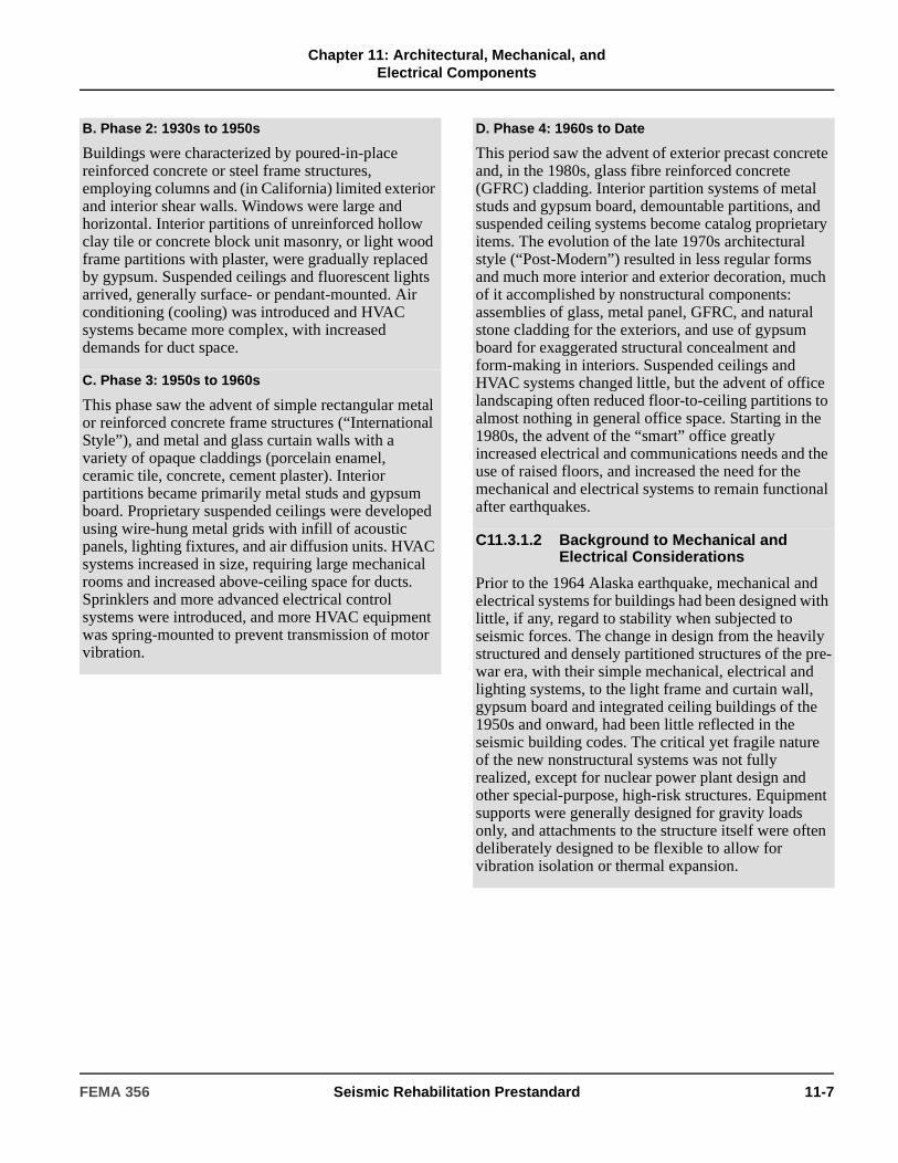
Chapter 11: Architectural, Mechanical, and
Electrical Components
B. Phase 2: 1930s to 1950s
Buildings were characterized by poured-in-place reinforced concrete or steel frame structures, employing columns and (in California) limited exterior and interior shear walls. Windows were large and horizontal. Interior partitions of unreinforced hollow clay tile or concrete block unit masonry, or light wood frame partitions with plaster, were gradually replaced by gypsum. Suspended ceilings and fluorescent lights arrived, generally surface- or pendant-mounted. Air conditioning (cooling) was introduced and HVAC systems became more complex, with increased demands for duct space.
C. Phase 3: 1950s to 1960s
This phase saw the advent of simple rectangular metal or reinforced concrete frame structures (“International Style”), and metal and glass curtain walls with a variety of opaque claddings (porcelain enamel, ceramic tile, concrete, cement plaster). Interior partitions became primarily metal studs and gypsum board. Proprietary suspended ceilings were developed using wire-hung metal grids with infill of acoustic panels, lighting fixtures, and air diffusion units. HVAC systems increased in size, requiring large mechanical rooms and increased above-ceiling space for ducts. Sprinklers and more advanced electrical control systems were introduced, and more HVAC equipment was spring-mounted to prevent transmission of motor vibration.
D. Phase 4: 1960s to Date
This period saw the advent of exterior precast concrete and, in the 1980s, glass fibre reinforced concrete (GFRC) cladding. Interior partition systems of metal studs and gypsum board, demountable partitions, and suspended ceiling systems become catalog proprietary items. The evolution of the late 1970s architectural style (“Post-Modern”) resulted in less regular forms and much more interior and exterior decoration, much of it accomplished by nonstructural components: assemblies of glass, metal panel, GFRC, and natural stone cladding for the exteriors, and use of gypsum board for exaggerated structural concealment and form-making in interiors. Suspended ceilings and HVAC systems changed little, but the advent of office landscaping often reduced floor-to-ceiling partitions to almost nothing in general office space. Starting in the 1980s, the advent of the “smart” office greatly increased electrical and communications needs and the use of raised floors, and increased the need for the mechanical and electrical systems to remain functional after earthquakes.
C11.3.1.2 Background to Mechanical and Electrical Considerations
Prior to the 1964 Alaska earthquake, mechanical and electrical systems for buildings had been designed with little, if any, regard to stability when subjected to seismic forces. The change in design from the heavily structured and densely partitioned structures of the pre-war era, with their simple mechanical, electrical and lighting systems, to the light frame and curtain wall, gypsum board and integrated ceiling buildings of the 1950s and onward, had been little reflected in the seismic building codes. The critical yet fragile nature of the new nonstructural systems was not fully realized, except for nuclear power plant design and other special-purpose, high-risk structures. Equipment supports were generally designed for gravity loads only, and attachments to the structure itself were often deliberately designed to be flexible to allow for vibration isolation or thermal expansion.
FEMA 356 Seismic Rehabilitation Prestandard 11-7

Chapter 11: Architectural, Mechanical, and
Electrical Components
Few building codes, even in regions with a history of seismic activity, have contained provisions governing the behavior of mechanical and electrical systems until relatively recently. One of the earliest references to seismic bracing can be found in NFPA-13, Standard for the Installation of Sprinkler Systems. This pamphlet has been updated periodically since 1896, and seismic bracing requirements have been included since 1947. Piping systems for building sprinklers are static and do not require vibration isolation. They do, however, require flexibility where the service piping enters the building. The issue of protecting flexibly mounted piping was not studied until after the 1964 Alaska earthquake.
The designers of building mechanical systems must also address the seismic restraints required for emergency generators, fire protection pumps, and plumbing systems that are vital parts of an effective fire suppression system.
Studies published following the 1971 San Fernando earthquake all indicated that buildings that sustained only minor structural damage became uninhabitable and hazardous to life due to failures of mechanical and electrical systems.
C11.3.1.3 HVAC Systems
A study by Ayres and Sun (1973b) clearly identified the need to anchor tanks and equipment that did not require vibration isolation, and to provide lateral restraints on equipment vibration isolation devices. Some of these suggested corrective measures are now incorporated into manufactured products. The HVAC system designers had to become aware of the earthquake-induced forces on the system’s components and the need for seismic restraints to limit damage; they also had to understand the requirements for the suspension and bracing of ceilings and light fixtures because of their adjacency to and interaction with the HVAC system components.
To provide technical guidance to HVAC system designers and installers, the Sheet Metal Industry Fund of Los Angeles published its first manual, Guidelines for Seismic Restraint of Mechanical Systems (Sheet Metal Industry Fund, 1976). This manual was updated in 1982 with assistance from the Plumbing and Piping Industry Council (PPIC). The most recent manual, Seismic Restraint Guidelines for Mechanical
Equipment (SMACNA, 1991), is designed for use in California as well as other locations with lower seismic hazard levels.
Secondary effects of earthquakes (fires, explosions, and hazardous materials releases resulting from damaged mechanical and electrical equipment) have only recently being considered. In addition, the potential danger of secondary damage from falling architectural and structural components, which could inflict major damage to adjacent equipment and render it unusable, needs to be carefully assessed.
These secondary effects can represent a considerable hazard to the building, its occupants, and its contents. Steam and hot water boilers and other pressure vessels can release fluids at hazardous temperatures. Mechanical systems often include piping systems filled with flammable, toxic, or noxious substances, such as ammonia or other refrigerants. Some of the nontoxic halogen refrigerants used in air-conditioning apparatus can be converted to a poisonous gas (phosgene) upon contact with open flame. Hot parts of disintegrating boilers, such as portions of the burner and firebrick, are at high enough temperatures to ignite combustible materials with which they might come in contact.
11-8 Seismic Rehabilitation Prestandard FEMA 356
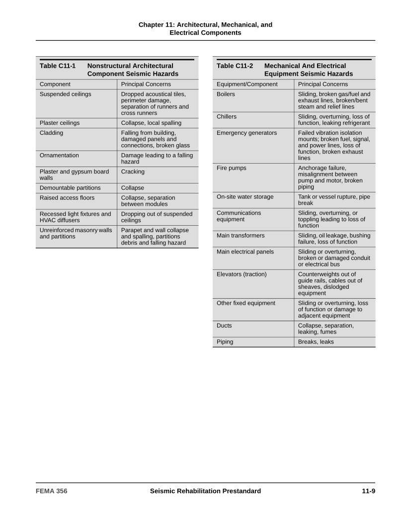
Chapter 11: Architectural, Mechanical, and
Electrical Components
Table C11-1 Nonstructural Architectural Component Seismic Hazards
Component Principal Concerns
Suspended ceilings Dropped acoustical tiles, perimeter damage, separation of runners and cross runners
Plaster ceilings Collapse, local spalling
Cladding Falling from building, damaged panels and connections, broken glass
Ornamentation Damage leading to a falling hazard
Plaster and gypsum board walls
Cracking
Demountable partitions Collapse
Raised access floors Collapse, separation between modules
Recessed light fixtures and HVAC diffusers
Dropping out of suspended ceilings
Unreinforced masonry walls and partitions
Parapet and wall collapse and spalling, partitions debris and falling hazard
Table C11-2 Mechanical And Electrical Equipment Seismic Hazards
Equipment/Component Principal Concerns
Boilers Sliding, broken gas/fuel and exhaust lines, broken/bent steam and relief lines
Chillers Sliding, overturning, loss of function, leaking refrigerant
Emergency generators Failed vibration isolation mounts; broken fuel, signal, and power lines, loss of function, broken exhaust lines
Fire pumps Anchorage failure, misalignment between pump and motor, broken piping
On-site water storage Tank or vessel rupture, pipe break
Communications equipment
Sliding, overturning, or toppling leading to loss of function
Main transformers Sliding, oil leakage, bushing failure, loss of function
Main electrical panels Sliding or overturning, broken or damaged conduit or electrical bus
Elevators (traction) Counterweights out of guide rails, cables out of sheaves, dislodged equipment
Other fixed equipment Sliding or overturning, loss of function or damage to adjacent equipment
Ducts Collapse, separation, leaking, fumes
Piping Breaks, leaks
FEMA 356 Seismic Rehabilitation Prestandard 11-9

Chapter 11: Architectural, Mechanical, and
Electrical Components
11.3.2 Component Evaluation
Nonstructural components shall be evaluated to achieve the Rehabilitation Objective selected in accordance with Section 1.4. Analysis and rehabilitation requirements for the Hazards Reduced, Life Safety, and Immediate Occupancy Nonstructural Performance Levels for the appropriate zone of seismicity shall be as specified in Table 11-1. Design forces shall be calculated in accordance with Section 11.7.3 or 11.7.4, and design deformations shall be calculated in accordance with Section 11.7.5. Analysis and rehabilitation requirements for the Hazards Reduced Nonstructural Performance Level shall follow the requirements for the Life Safety Nonstructural Performance Level. Analysis and rehabilitation requirements for the Operational Nonstructural Performance Level shall be based on approved codes.
Acceptance criteria for nonstructural components being evaluated to the Life Safety and Immediate Occupancy Nonstructural Performance Levels shall be based on criteria listed in Sections 11.9 through 11.11. Forces on bracing and connections for nonstructural components calculated in accordance with Section 11.7 shall be compared to capacities using strength design procedures. Acceptance criteria for the Life Safety Nonstructural Performance Level shall be used for nonstructural components being evaluated to the Hazards Reduced Nonstructural Performance Level. For nonstructural components being evaluated to the Operational Nonstructural Performance Level, approved acceptance criteria shall be used.
C11.3.2 Component Evaluation
The Hazards Reduced Nonstructural Performance Level applies only to high hazard components as specified in Section 1.5.2.4 and Table 11-1. Life Safety Nonstructural Performance Level criteria—or other approved criteria—should be used for the Hazards Reduced Nonstructural Performance Level. Criteria for the Operational Nonstructural Performance Level has not been developed to date. Evaluation, rehabilitation, and acceptance criteria for the Immediate Occupancy Nonstructural Performance Level may be used for the Operational Nonstructural Performance Level if more appropriate data are not available.
Forces on nonstructural components calculated in accordance with Section 11.7 are at a strength design level. Where allowable stress values are available for proprietary products used as bracing for nonstructural components, these values shall be factored up to strength design levels. In the absence of manufacturer’s data on strength values, allowable stress values can be increased by a factor of 1.4 to obtain strength design values.
When nonstructural components are evaluated using Hazards Reduced Nonstructural Performance Level, the force level associated with Life Safety Nonstructural Performance in Section 11.7 should be used. In many instances, if bracing of the nonstructural component exists, or if it is rehabilitated, there would not be a substantial justification for evaluating or rehabilitating the component using a force level or acceptance criteria less stringent than Life Safety. However, in cases where it is not considered critical or feasible, the engineer may, with appropriate approval, evaluate or rehabilitate the nonstructural component using a criteria that is less stringent than Life Safety.
In cases where the Basic Safety Objective is not required—such as when the Limited Safety Performance Range applies—there may be more latitude in the selection of components or criteria for nonstructural rehabilitation.
A suggested general procedure for developing a mitigation plan for the rehabilitation of nonstructural components is as follows:
1. It is assumed that the building has been evaluated in a feasibility phase, using a procedure such as that described in FEMA 310. For nonstructural components, use of this procedure will have provided a broad list of deficiencies that are generally, but not specifically, related to a Rehabilitation Objective. Issues related to other objectives and possible nonstructural components not discussed in FEMA 310, as well as issues raised by nonstructural rehabilitation unaccompanied by structural rehabilitation (e.g., planning, cost-benefit) are outlined in this commentary, and references are provided for more detailed investigation.
2. The decision is made to rehabilitate the building, either structurally, nonstructurally, or both.
11-10 Seismic Rehabilitation Prestandard FEMA 356

Chapter 11: Architectural, Mechanical, and
Electrical Components
11.4 Rehabilitation Objectives and Performance Levels
Rehabilitation objectives that include performance levels for nonstructural components shall be established in accordance with Section 1.4. The zone of seismicity shall be determined in accordance with Section 1.6.3.
3. From Chapter 2 of this standard, the designer reviews Rehabilitation Objectives and, in concert with the owner, determines the objective. Alternatively, the objective may have been already defined in an ordinance or other policy.
4. Following a decision on the Rehabilitation Objective, which includes the Nonstructural Performance Level or Range as well as ground motion criteria, the designer consults Chapter 11 of this standard.
5. Using Chapter 11, the designer prepares a definitive list of nonstructural components that are within the scope of the rehabilitation, based on the selected Nonstructural Performance Level and an assessment of component condition. For the Life Safety Nonstructural Performance Level and, to some extent, the Immediate Occupancy Nonstructural Performance Level, Chapters 2 and 11 of this standard specify requirements. However, for other levels and ranges, there is a need to evaluate and prioritize. From the list of nonstructural components within the project scope, a design assessment is made to determine if the component requires rehabilitation and, from Table 11-1, the rehabilitation Analysis Method (Analytical or Prescriptive) for each component or component group is determined.
6. For those components that do not meet the criteria, an appropriate analysis and design procedure is undertaken, with the aim of bringing the component into compliance with the criteria appropriate to the Nonstructural Performance Level or Range and the ground motion criteria.
7. Nonstructural rehabilitation design documents are prepared.
C11.4 Rehabilitation Objectives and Performance Levels
The nonstructural Rehabilitation Objective may be the same as the Structural Rehabilitation Objective, or it may differ. For the BSO, structural and nonstructural requirements specified in this standard must be met.
This standard is also intended to be applicable to the situation where nonstructural—but not structural—components are to be rehabilitated. Rehabilitation that is restricted to the nonstructural components will typically fall within the Limited Safety Nonstructural Performance Range unless the structure is already determined to meet a specified Rehabilitation Objective. To qualify for any Rehabilitation Objective higher than Limited Safety, consideration of structural behavior is necessary to properly take into account loads on nonstructural components generated by inertial forces or deformations imposed by the structure.
C11.4.1 Regional Seismicity and Nonstructural Components
Requirements for the rehabilitation of nonstructural components relating to the three Seismic Zones—High, Moderate, and Low—are shown in Table 11-1 and noted in each section, where applicable. In general, in regions of low seismicity, certain nonstructural components have no rehabilitation requirements with respect to the Life Safety Nonstructural Performance Level. Rehabilitation of these components, particularly where rehabilitation is simple, may nevertheless be desirable for damage control and property loss reduction.
C11.4.2 Means of Egress: Escape and Rescue
Preservation of egress is accomplished primarily by ensuring that the most hazardous nonstructural elements are replaced or rehabilitated. The items listed in Table 11-1 for achieving the Life Safety Nonstructural Performance Level show that typical requirements for maintaining egress will, in effect, be accomplished if the egress-related components are addressed. These would include the following items listed in FEMA 310.
1. Walls around stairs, elevator enclosures, and corridors are not hollow clay tile or unreinforced masonry.
FEMA 356 Seismic Rehabilitation Prestandard 11-11

Chapter 11: Architectural, Mechanical, and
Electrical Components
11.5 Structural-Nonstructural Interaction
11.5.1 Response Modification
Nonstructural components shall be included in the mathematical model of the building in accordance with the requirements of Section 3.2.2.3. Nonstructural components included in the mathematical model of the building shall be evaluated for forces and deformations imposed by the structure, computed in accordance with Chapter 3.
11.5.2 Base Isolation
In a base-isolated structure, nonstructural components located at or above the isolation interface shall comply with the requirements in Section 9.2.6.2.1. Nonstructural components that cross the isolation interface shall comply with the requirements of Section 9.2.6.2.2. Nonstructural components located below the isolation interface shall comply with the requirements of this chapter.
11.6 Classification of Acceleration-Sensitive and Deformation-Sensitive Components
Nonstructural components shall be classified based on their response sensitivity as follows:
1. Nonstructural components that are sensitive to and subject to damage from inertial loading shall be classified as acceleration-sensitive components.
2. Nonstructural components that are sensitive to deformation imposed by drift or deformation of the structure shall be classified as deformation-sensitive components. Nonstructural components that are sensitive to both the inertial loading and deformation of the structure shall also be classified as deformation-sensitive components.
2. Stair enclosures do not contain any piping or equipment except as required for life safety.
3. Veneers, cornices, and other ornamentation above building exits are well anchored to the structural system.
4. Parapets and canopies are anchored and braced to prevent collapse and blockage of building exits.
Beyond this, the following list describes some conditions that might be commonly recognized as representing major obstruction; the building should be inspected to see whether these, or any similar hazardous conditions exist. If so, their replacement or rehabilitation should be included in the rehabilitation plan.
1. Partitions taller than six feet and weighing more than five pounds per square foot, if collapse of the entire partition—rather than cracking—is the expected mode of failure, and if egress would be impeded.
2. Ceilings, soffits, or any ceiling or decorative ceiling component weighing more than two pounds per square foot, if it is expected that large areas (pieces measuring ten square feet or larger) would fall.
3. Potential for falling ceiling-located light fixtures or piping; diffusers and ductwork, speakers and alarms, and other objects located higher than 42 inches off the floor.
4. Potential for falling debris weighing more than 100 pounds that, if it fell in an earthquake, would obstruct a required exit door or other component, such as a rescue window or fire escape.
5. Potential for jammed doors or windows required as part of an exit path—including doors to individual offices, rest rooms, and other occupied spaces.
Of these, the first four are also taken care of in the Life Safety Nonstructural Performance Level requirement. The last condition is very difficult to remove with any assurance, except for low levels of shaking in which structural drift and deformation will be minimal, and the need for escape and rescue correspondingly slight.
11-12 Seismic Rehabilitation Prestandard FEMA 356
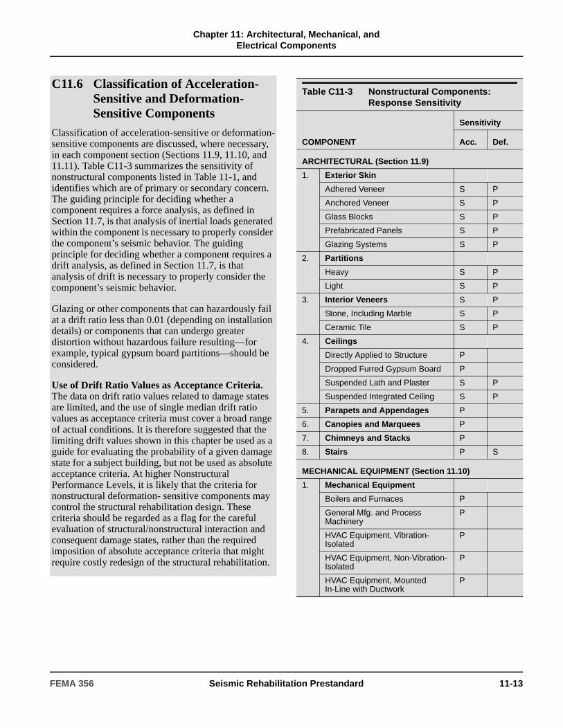
Chapter 11: Architectural, Mechanical, and
Electrical Components
C11.6 Classification of Acceleration-Sensitive and Deformation-Sensitive Components
Classification of acceleration-sensitive or deformation-sensitive components are discussed, where necessary, in each component section (Sections 11.9, 11.10, and 11.11). Table C11-3 summarizes the sensitivity of nonstructural components listed in Table 11-1, and identifies which are of primary or secondary concern. The guiding principle for deciding whether a component requires a force analysis, as defined in Section 11.7, is that analysis of inertial loads generated within the component is necessary to properly consider the component’s seismic behavior. The guiding principle for deciding whether a component requires a drift analysis, as defined in Section 11.7, is that analysis of drift is necessary to properly consider the component’s seismic behavior.
Glazing or other components that can hazardously fail at a drift ratio less than 0.01 (depending on installation details) or components that can undergo greater distortion without hazardous failure resulting—for example, typical gypsum board partitions—should be considered.
Use of Drift Ratio Values as Acceptance Criteria. The data on drift ratio values related to damage states are limited, and the use of single median drift ratio values as acceptance criteria must cover a broad range of actual conditions. It is therefore suggested that the limiting drift values shown in this chapter be used as a guide for evaluating the probability of a given damage state for a subject building, but not be used as absolute acceptance criteria. At higher Nonstructural Performance Levels, it is likely that the criteria for nonstructural deformation- sensitive components may control the structural rehabilitation design. These criteria should be regarded as a flag for the careful evaluation of structural/nonstructural interaction and consequent damage states, rather than the required imposition of absolute acceptance criteria that might require costly redesign of the structural rehabilitation.
Table C11-3 Nonstructural Components: Response Sensitivity
COMPONENT
Sensitivity
Acc. Def.
ARCHITECTURAL (Section 11.9)
1. Exterior Skin
Adhered Veneer S P
Anchored Veneer S P
Glass Blocks S P
Prefabricated Panels S P
Glazing Systems S P
2. Partitions
Heavy S P
Light S P
3. Interior Veneers S P
Stone, Including Marble S P
Ceramic Tile S P
4. Ceilings
Directly Applied to Structure P
Dropped Furred Gypsum Board P
Suspended Lath and Plaster S P
Suspended Integrated Ceiling S P
5. Parapets and Appendages P
6. Canopies and Marquees P
7. Chimneys and Stacks P
8. Stairs P S
MECHANICAL EQUIPMENT (Section 11.10)
1. Mechanical Equipment
Boilers and Furnaces P
General Mfg. and Process Machinery
P
HVAC Equipment, Vibration-Isolated
P
HVAC Equipment, Non-Vibration-Isolated
P
HVAC Equipment, Mounted In-Line with Ductwork
P
FEMA 356 Seismic Rehabilitation Prestandard 11-13

Chapter 11: Architectural, Mechanical, and
Electrical Components
11.7 Evaluation ProceduresOne of the following evaluation procedures for nonstructural components shall be selected based on the requirements of Table 11-1:
1. Analytical Procedure.
2. Prescriptive Procedure.
11.7.1 Analytical Procedure
When the Prescriptive Procedure is not permitted based on Table 11-1, forces and deformations on nonstructural components shall be calculated as follows:
1. If a force analysis only is permitted by Table 11-1 and either the Hazards Reduced or Life Safety Nonstructural Performance Level is selected, then use of the default equations given in Section 11.7.3 shall be permitted to calculate seismic design forces on nonstructural components.
2. If a force analysis only is permitted by Table 11-1 and a Nonstructural Performance Level higher than Life Safety is selected, then the default equations of Section 11.7.3 do not apply, and seismic design
forces shall be calculated in accordance with Section 11.7.4.
3. If both force and deformation analysis are required by Table 11-1, then seismic design forces shall be calculated in accordance with Section 11.7.4 and drift ratios or relative displacements shall be calculated in accordance with Section 11.7.5. The deformation and associated drift ratio of the structural component(s) to which the deformation-sensitive nonstructural component is attached shall be determined in accordance with Chapter 3.
4. Alternatively, the calculation of seismic design forces and deformations in accordance with Section 11.7.6 shall be permitted.
11.7.2 Prescriptive Procedure
Where the Prescriptive Procedure is permitted in Table 11-1, the characteristics of the nonstructural component shall be compared with characteristics as specified in approved codes.
2. Storage Vessels and Water Heaters
Structurally Supported Vessels (Category 1)
P
Flat Bottom Vessels (Category 2) P
3. Pressure Piping P S
4. Fire Suppression Piping P S
5. Fluid Piping, not Fire Suppression
Hazardous Materials P S
Nonhazardous Materials P S
6. Ductwork P S
Acc. = Acceleration-Sensitive P = Primary Response
Def. = Deformation-Sensitive S = Secondary Response
Table C11-3 Nonstructural Components: Response Sensitivity (continued)
COMPONENT
Sensitivity
Acc. Def.
C11.7.1 Analytical Procedure
For nonstructural components, the Analytical Procedure, which consists of the default equation and general equation approaches, is applicable to any case. The Prescriptive Procedure is limited by Table 11-1 to specified combinations of seismicity and component type for compliance with the Life Safety Nonstructural Performance Level.
C11.7.2 Prescriptive Procedure
A Prescriptive Procedure consists of published standards and references that describe the design concepts and construction features that must be present for a given nonstructural component to be seismically protected. No engineering calculations are required in a Prescriptive Procedure, although in some cases an engineering review of the design and installation is required.
Suggested references for prescriptive requirements are listed in the commentary of the “Component Behavior and Rehabilitation Concepts” subsection of Sections 11.9 through 11.11 for each component type.
11-14 Seismic Rehabilitation Prestandard FEMA 356
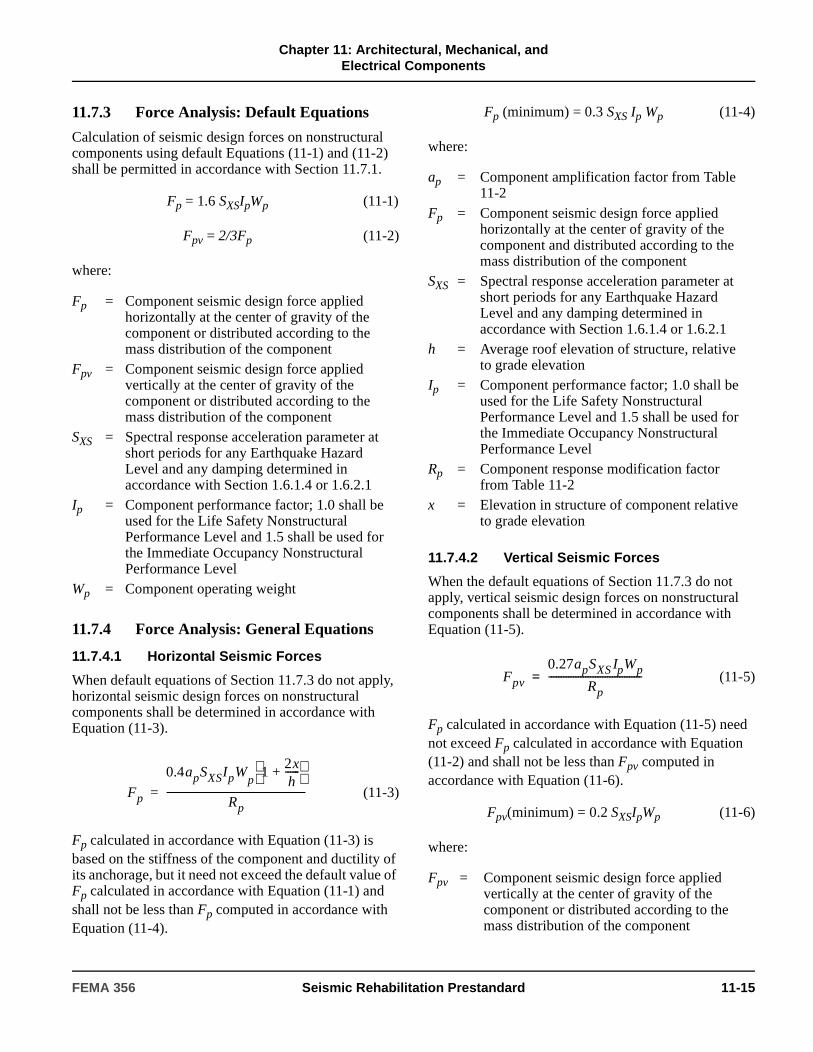
Chapter 11: Architectural, Mechanical, and
Electrical Components
11.7.3 Force Analysis: Default Equations
Calculation of seismic design forces on nonstructural components using default Equations (11-1) and (11-2) shall be permitted in accordance with Section 11.7.1.
Fp = 1.6 SXSIpWp (11-1)
Fpv = 2/3Fp (11-2)
where:
11.7.4 Force Analysis: General Equations
11.7.4.1 Horizontal Seismic Forces
When default equations of Section 11.7.3 do not apply, horizontal seismic design forces on nonstructural components shall be determined in accordance with Equation (11-3).
(11-3)
Fp calculated in accordance with Equation (11-3) is based on the stiffness of the component and ductility of its anchorage, but it need not exceed the default value of Fp calculated in accordance with Equation (11-1) and shall not be less than Fp computed in accordance with Equation (11-4).
Fp (minimum) = 0.3 SXS Ip Wp (11-4)
where:
11.7.4.2 Vertical Seismic Forces
When the default equations of Section 11.7.3 do not apply, vertical seismic design forces on nonstructural components shall be determined in accordance with Equation (11-5).
(11-5)
Fp calculated in accordance with Equation (11-5) need not exceed Fp calculated in accordance with Equation (11-2) and shall not be less than Fpv computed in accordance with Equation (11-6).
Fpv(minimum) = 0.2 SXSIpWp (11-6)
where:
Fp = Component seismic design force applied horizontally at the center of gravity of the component or distributed according to the mass distribution of the component
Fpv = Component seismic design force applied vertically at the center of gravity of the component or distributed according to the mass distribution of the component
SXS = Spectral response acceleration parameter at short periods for any Earthquake Hazard Level and any damping determined in accordance with Section 1.6.1.4 or 1.6.2.1
Ip = Component performance factor; 1.0 shall be used for the Life Safety Nonstructural Performance Level and 1.5 shall be used for the Immediate Occupancy Nonstructural Performance Level
Wp = Component operating weight
Fp
0.4apSXSIpWp
12xh
------+
Rp---------------------------------------------------------=
ap = Component amplification factor from Table 11-2
Fp = Component seismic design force applied horizontally at the center of gravity of the component and distributed according to the mass distribution of the component
SXS = Spectral response acceleration parameter at short periods for any Earthquake Hazard Level and any damping determined in accordance with Section 1.6.1.4 or 1.6.2.1
h = Average roof elevation of structure, relative to grade elevation
Ip = Component performance factor; 1.0 shall be used for the Life Safety Nonstructural Performance Level and 1.5 shall be used for the Immediate Occupancy Nonstructural Performance Level
Rp = Component response modification factor from Table 11-2
x = Elevation in structure of component relative to grade elevation
Fpv = Component seismic design force applied vertically at the center of gravity of the component or distributed according to the mass distribution of the component
Fpv
0.27apSXS IpWp
Rp--------------------------------------=
FEMA 356 Seismic Rehabilitation Prestandard 11-15
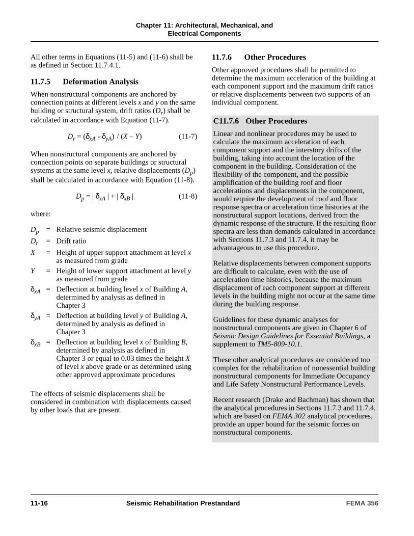
Chapter 11: Architectural, Mechanical, and
Electrical Components
All other terms in Equations (11-5) and (11-6) shall be as defined in Section 11.7.4.1.
11.7.5 Deformation Analysis
When nonstructural components are anchored by connection points at different levels x and y on the same building or structural system, drift ratios (Dr) shall be calculated in accordance with Equation (11-7).
Dr = (δxA - δyA) / (X – Y) (11-7)
When nonstructural components are anchored by connection points on separate buildings or structural systems at the same level x, relative displacements (Dp) shall be calculated in accordance with Equation (11-8).
Dp = | δxA | + | δxB | (11-8)
where:
The effects of seismic displacements shall be considered in combination with displacements caused by other loads that are present.
11.7.6 Other Procedures
Other approved procedures shall be permitted to determine the maximum acceleration of the building at each component support and the maximum drift ratios or relative displacements between two supports of an individual component.
Dp = Relative seismic displacement
Dr = Drift ratio
X = Height of upper support attachment at level x as measured from grade
Y = Height of lower support attachment at level y as measured from grade
δxA = Deflection at building level x of Building A, determined by analysis as defined in Chapter 3
δyA = Deflection at building level y of Building A, determined by analysis as defined in Chapter 3
δxB = Deflection at building level x of Building B, determined by analysis as defined in Chapter 3 or equal to 0.03 times the height X of level x above grade or as determined using other approved approximate procedures
C11.7.6 Other Procedures
Linear and nonlinear procedures may be used to calculate the maximum acceleration of each component support and the interstory drifts of the building, taking into account the location of the component in the building. Consideration of the flexibility of the component, and the possible amplification of the building roof and floor accelerations and displacements in the component, would require the development of roof and floor response spectra or acceleration time histories at the nonstructural support locations, derived from the dynamic response of the structure. If the resulting floor spectra are less than demands calculated in accordance with Sections 11.7.3 and 11.7.4, it may be advantageous to use this procedure.
Relative displacements between component supports are difficult to calculate, even with the use of acceleration time histories, because the maximum displacement of each component support at different levels in the building might not occur at the same time during the building response.
Guidelines for these dynamic analyses for nonstructural components are given in Chapter 6 of Seismic Design Guidelines for Essential Buildings, a supplement to TM5-809-10.1.
These other analytical procedures are considered too complex for the rehabilitation of nonessential building nonstructural components for Immediate Occupancy and Life Safety Nonstructural Performance Levels.
Recent research (Drake and Bachman) has shown that the analytical procedures in Sections 11.7.3 and 11.7.4, which are based on FEMA 302 analytical procedures, provide an upper bound for the seismic forces on nonstructural components.
11-16 Seismic Rehabilitation Prestandard FEMA 356

Chapter 11: Architectural, Mechanical, and
Electrical Components
Table 11-2 Nonstructural Component Amplification and Response Modification Factors
COMPONENT ap1 Rp
2
ARCHITECTURAL (Section 11.9)
1. Exterior Wall Elements
Adhered Veneer 1 4
Anchored Veneer 1 33
Glass Block 1 2
Prefabricated Panels 1 33
Glazed Exterior Wall Systems 1 2
2. Partitions
Heavy 1 1.5
Light 1 3
Glazed 1 2
3. Interior Veneers
Stone, Including Marble 1 1.5
Ceramic Tile 1 1.5
4. Ceilings
Directly Applied to Structure 1 1.5
Dropped Furred Gypsum Board 1 1.5
Suspended Lath and Plaster 1 1.5
Suspended Integrated Ceiling 1 1.5
5. Parapets and Appendages 2.5 1.25
6. Canopies and Marquees 2.5 1.5
7. Chimneys and Stacks 2.5 1.25
8. Stairs 1 3
MECHANICAL EQUIPMENT (Section 11.10)
1. Mechanical Equipment
Boilers, Furnaces, Pumps, and Chillers 1 3
General Mfg. and Process Machinery 1 3
HVAC Equipment, Vibration-Isolated 2.5 3
HVAC Equipment, Non-Vibration-Isolated 1 3
HVAC Equipment, Mounted In-Line with Ductwork 1 3
2. Storage Vessels and Water Heaters
Vessels on Legs (Category 1) 2.5 1.5
Flat Bottom Vessels (Category 2) 2.5 3
3. High-Pressure Piping 2.5 4
4. Fire Suppression Piping 2.5 4
5. Fluid Piping, not Fire Suppression
Hazardous Materials 2.5 1
Nonhazardous Materials 2.5 4
FEMA 356 Seismic Rehabilitation Prestandard 11-17

Chapter 11: Architectural, Mechanical, and
Electrical Components
6. Ductwork 1 3
ELECTRICAL AND COMMUNICATIONS EQUIPMENT (Section 11.11)
1. Electrical and Communications Equipment 1 3
2. Electrical and Communications Distribution Equipment 2.5 5
3. Light Fixtures
Recessed 1 1.5
Surface Mounted 1 1.5
Integrated Ceiling 1 1.5
Pendant 1 1.5
FURNISHINGS AND INTERIOR EQUIPMENT (Section 11.11)
1. Storage Racks4 2.5 4
2. Bookcases 1 3
3. Computer Access Floors 1 3
4. Hazardous Materials Storage 2.5 1
5. Computer and Communications Racks 2.5 6
6. Elevators 1 3
7. Conveyors 2.5 3
1. A lower value for ap shall be permitted if justified by detailed dynamic analysis. The value for ap shall be not less than 1. Where flexible diaphragms provide lateral support for walls and partitions, the value of ap shall be increased to 2.0 for the center one-half of the span.
The value of ap = 1 is for equipment generally regarded as rigid and rigidly attached. The value of ap = 2.5 is for equipment generally regarded as flexible and flexibly attached. See the definitions (Section 11.12) for explanations of “Component, rigid” and “Component, flexible.”
2. For anchorage design where component anchorage is provided by expansion anchor bolts, shallow chemical anchors, or shallow (nonductile) cast-in-place anchors, or where the component is constructed of nonductile materials, Rp shall be taken as 1.5.
Shallow anchors are those with an embedment length-to-bolt diameter ratio of less than 8.
3. Values shall apply when attachment is of ductile material and design, otherwise 1.5.
4. Storage racks over six feet in height shall be designed in accordance with the provisions of Section 11.11.1.
Table 11-2 Nonstructural Component Amplification and Response Modification Factors (continued)
COMPONENT ap1 Rp
2
11-18 Seismic Rehabilitation Prestandard FEMA 356
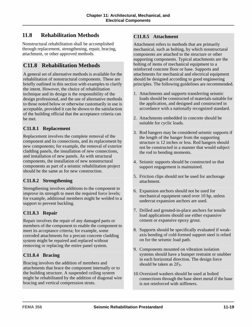
Chapter 11: Architectural, Mechanical, and
Electrical Components
11.8 Rehabilitation MethodsNonstructural rehabilitation shall be accomplished through replacement, strengthening, repair, bracing, attachment, or other approved methods.
C11.8 Rehabilitation MethodsA general set of alternative methods is available for the rehabilitation of nonstructural components. These are briefly outlined in this section with examples to clarify the intent. However, the choice of rehabilitation technique and its design is the responsibility of the design professional, and the use of alternative methods to those noted below or otherwise customarily in use is acceptable, provided it can be shown to the satisfaction of the building official that the acceptance criteria can be met.
C11.8.1 Replacement
Replacement involves the complete removal of the component and its connections, and its replacement by new components; for example, the removal of exterior cladding panels, the installation of new connections, and installation of new panels. As with structural components, the installation of new nonstructural components as part of a seismic rehabilitation project should be the same as for new construction.
C11.8.2 Strengthening
Strengthening involves additions to the component to improve its strength to meet the required force levels; for example, additional members might be welded to a support to prevent buckling.
C11.8.3 Repair
Repair involves the repair of any damaged parts or members of the component to enable the component to meet its acceptance criteria; for example, some corroded attachments for a precast concrete cladding system might be repaired and replaced without removing or replacing the entire panel system.
C11.8.4 Bracing
Bracing involves the addition of members and attachments that brace the component internally or to the building structure. A suspended ceiling system might be rehabilitated by the addition of diagonal wire bracing and vertical compression struts.
C11.8.5 Attachment
Attachment refers to methods that are primarily mechanical, such as bolting, by which nonstructural components are attached to the structure or other supporting components. Typical attachments are the bolting of items of mechanical equipment to a reinforced concrete floor or base. Supports and attachments for mechanical and electrical equipment should be designed according to good engineering principles. The following guidelines are recommended.
1. Attachments and supports transferring seismic loads should be constructed of materials suitable for the application, and designed and constructed in accordance with a nationally recognized standard.
2. Attachments embedded in concrete should be suitable for cyclic loads.
3. Rod hangers may be considered seismic supports if the length of the hanger from the supporting structure is 12 inches or less. Rod hangers should not be constructed in a manner that would subject the rod to bending moments.
4. Seismic supports should be constructed so that support engagement is maintained.
5. Friction clips should not be used for anchorage attachment.
6. Expansion anchors should not be used for mechanical equipment rated over 10 hp, unless undercut expansion anchors are used.
7. Drilled and grouted-in-place anchors for tensile load applications should use either expansive cement or expansive epoxy grout.
8. Supports should be specifically evaluated if weak-axis bending of cold-formed support steel is relied on for the seismic load path.
9. Components mounted on vibration isolation systems should have a bumper restraint or snubber in each horizontal direction. The design force should be taken as 2Fp.
10.Oversized washers should be used at bolted connections through the base sheet metal if the base is not reinforced with stiffeners.
FEMA 356 Seismic Rehabilitation Prestandard 11-19
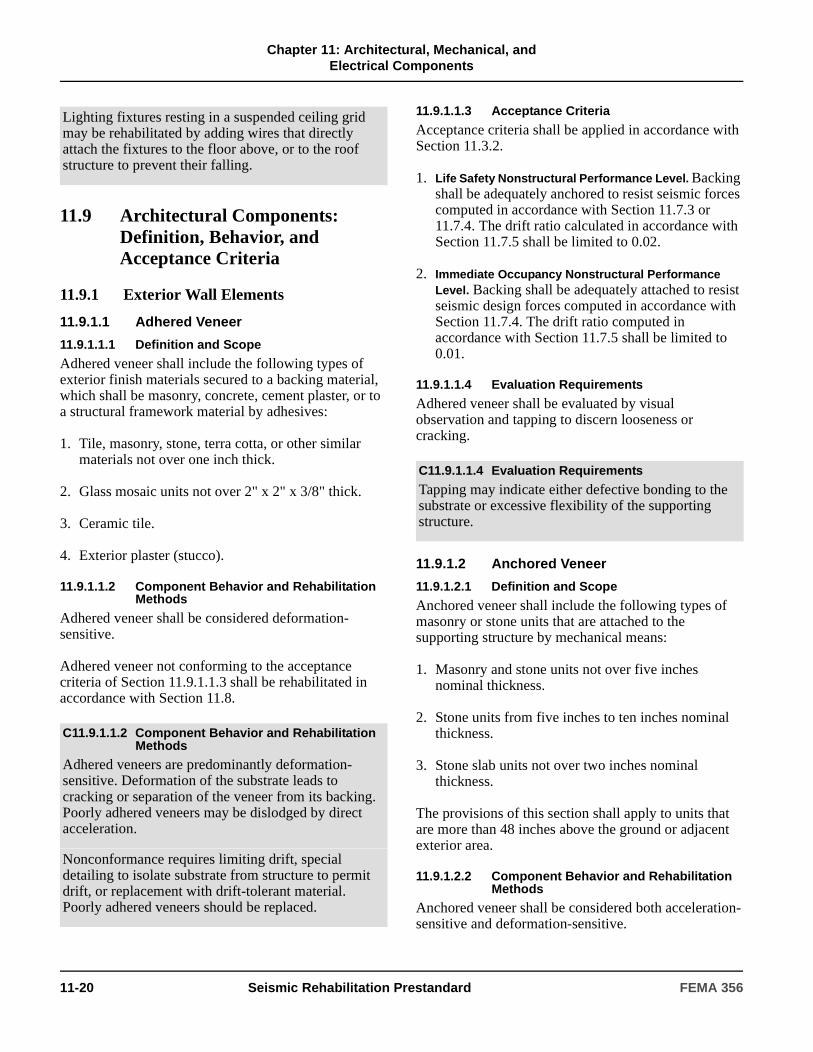
Chapter 11: Architectural, Mechanical, and
Electrical Components
11.9 Architectural Components: Definition, Behavior, and Acceptance Criteria
11.9.1 Exterior Wall Elements
11.9.1.1 Adhered Veneer
11.9.1.1.1 Definition and Scope
Adhered veneer shall include the following types of exterior finish materials secured to a backing material, which shall be masonry, concrete, cement plaster, or to a structural framework material by adhesives:
1. Tile, masonry, stone, terra cotta, or other similar materials not over one inch thick.
2. Glass mosaic units not over 2" x 2" x 3/8" thick.
3. Ceramic tile.
4. Exterior plaster (stucco).
11.9.1.1.2 Component Behavior and Rehabilitation Methods
Adhered veneer shall be considered deformation-sensitive.
Adhered veneer not conforming to the acceptance criteria of Section 11.9.1.1.3 shall be rehabilitated in accordance with Section 11.8.
11.9.1.1.3 Acceptance Criteria
Acceptance criteria shall be applied in accordance with Section 11.3.2.
1. Life Safety Nonstructural Performance Level. Backing shall be adequately anchored to resist seismic forces computed in accordance with Section 11.7.3 or 11.7.4. The drift ratio calculated in accordance with Section 11.7.5 shall be limited to 0.02.
2. Immediate Occupancy Nonstructural Performance Level. Backing shall be adequately attached to resist seismic design forces computed in accordance with Section 11.7.4. The drift ratio computed in accordance with Section 11.7.5 shall be limited to 0.01.
11.9.1.1.4 Evaluation Requirements
Adhered veneer shall be evaluated by visual observation and tapping to discern looseness or cracking.
11.9.1.2 Anchored Veneer
11.9.1.2.1 Definition and Scope
Anchored veneer shall include the following types of masonry or stone units that are attached to the supporting structure by mechanical means:
1. Masonry and stone units not over five inches nominal thickness.
2. Stone units from five inches to ten inches nominal thickness.
3. Stone slab units not over two inches nominal thickness.
The provisions of this section shall apply to units that are more than 48 inches above the ground or adjacent exterior area.
11.9.1.2.2 Component Behavior and Rehabilitation Methods
Anchored veneer shall be considered both acceleration-sensitive and deformation-sensitive.
Lighting fixtures resting in a suspended ceiling grid may be rehabilitated by adding wires that directly attach the fixtures to the floor above, or to the roof structure to prevent their falling.
C11.9.1.1.2 Component Behavior and Rehabilitation Methods
Adhered veneers are predominantly deformation-sensitive. Deformation of the substrate leads to cracking or separation of the veneer from its backing. Poorly adhered veneers may be dislodged by direct acceleration.
Nonconformance requires limiting drift, special detailing to isolate substrate from structure to permit drift, or replacement with drift-tolerant material. Poorly adhered veneers should be replaced.
C11.9.1.1.4 Evaluation Requirements
Tapping may indicate either defective bonding to the substrate or excessive flexibility of the supporting structure.
11-20 Seismic Rehabilitation Prestandard FEMA 356

Chapter 11: Architectural, Mechanical, and
Electrical Components
Anchored veneer and connections not conforming to the acceptance criteria of Section 11.9.1.2.3 shall be rehabilitated in accordance with Section 11.8.
11.9.1.2.3 Acceptance Criteria
Acceptance criteria shall be applied in accordance with Section 11.3.2.
1. Life Safety Nonstructural Performance Level. Backing shall be adequately anchored to resist seismic forces computed in accordance with Section 11.7.3 or 11.7.4. The drift ratio calculated in accordance with Section 11.7.5 shall be limited to 0.02.
2. Immediate Occupancy Nonstructural Performance Level. Backing shall be adequately attached to resist seismic design forces computed in accordance with Section 11.7.4. The drift ratio computed in accordance with Section 11.7.5 shall be limited to 0.01.
11.9.1.2.4 Evaluation Requirements
Stone units shall have adequate stability, joint detailing, and maintenance to prevent moisture penetration from weather that could destroy the anchors. The anchors shall be visually inspected and tested to determine capacity if any signs of deterioration are visible.
11.9.1.3 Glass Block Units and Other Nonstructural Masonry
11.9.1.3.1 Definition and Scope
Glass block and other units that are self-supporting for static vertical loads, held together by mortar and
structurally detached from the surrounding structure, shall be rehabilitated in accordance with this section.
11.9.1.3.2 Component Behavior and Rehabilitation Methods
Glass block units and other nonstructural masonry shall be considered both acceleration- and deformation-sensitive.
Rehabilitation of individual walls less than 144 square feet or 15 feet in any dimension using Prescriptive Procedures based on Section 2110 of IBC (2000) shall be permitted. For walls larger than 144 square feet or 15 feet in any dimension, the analytical procedure shall be used.
Glass block units and other nonstructural masonry not conforming with the requirements of Section 11.9.1.3.3 shall be rehabilitated in accordance with Section 11.8.
11.9.1.3.3 Acceptance Criteria
Acceptance criteria shall be applied in accordance with Section 11.3.2.
1. Life Safety Nonstructural Performance Level. Glass block and other nonstructural masonry walls and their enclosing framing, shall be capable of resisting both in-plane and out-of-plane forces computed in accordance with Section 11.7.3 or 11.7.4, or shall meet the requirements of the Prescriptive Procedure if permitted. The drift ratio calculated in accordance with Section 11.7.5 shall be limited to 0.02.
C11.9.1.2.2 Component Behavior and Rehabilitation Methods
Anchored veneer is both acceleration- and deformation-sensitive. Heavy units may be dislodged by direct acceleration, which distorts or fractures the mechanical connections. Deformation of the supporting structure, particularly if it is a frame, may similarly affect the connections, and the units may be displaced or dislodged by racking.
Drift analysis is necessary to establish conformance with drift acceptance criteria related to performance level. Nonconformance requires limiting structural drift, or special detailing to isolate substrate from structure to permit drift. Defective connections must be replaced.
C11.9.1.3.2 Component Behavior and Rehabilitation Methods
Failure in-plane generally occurs by deformation in the surrounding structure that results in unit cracking and displacement along the cracks. Failure out-of-plane takes the form of dislodgment or collapse caused by direct acceleration.
Nonconformance with deformation criteria requires limiting structural drift, or special detailing to isolate the glass block wall from the surrounding structure to permit drift. Sufficient reinforcing must be provided to deal with out-of-plane forces. Large walls may need to be subdivided by additional structural supports into smaller areas that can meet the drift or force acceptance criteria.
FEMA 356 Seismic Rehabilitation Prestandard 11-21
Chapter 11: Architectural, Mechanical, and
Electrical Components
2. Immediate Occupancy Nonstructural Performance Level. Glass block and other nonstructural masonry walls and their enclosing framing shall be capable of resisting both in-plane and out-of-plane forces computed in accordance with Section 11.7.4. The drift ratio calculated in accordance with Section 11.7.5 shall be limited to 0.01.
11.9.1.3.4 Evaluation Requirements
Glass block units and other nonstructural masonry shall be evaluated based on the criteria of Section 2110 of IBC (2000).
11.9.1.4 Prefabricated Panels
11.9.1.4.1 Definition and Scope
The following types of prefabricated panels designed to resist wind, seismic, and other applied forces shall be rehabilitated in accordance with this section:
1. Precast concrete, and concrete panels with facing (generally stone) laminated or mechanically attached.
2. Laminated metal-faced insulated panels.
3. Steel strong-back panels with insulated, water- resistant facing, or mechanically attached metal or stone facing.
11.9.1.4.2 Component Behavior and Rehabilitation Methods
Prefabricated panels shall be considered both acceleration- and deformation-sensitive.
Prefabricated panels not conforming to the acceptance criteria of Section 11.9.1.4.3 shall be rehabilitated in accordance with Section 11.8.
11.9.1.4.3 Acceptance Criteria
Acceptance criteria shall be applied in accordance with Section 11.3.2.
1. Life Safety Nonstructural Performance Level. Prefabricated panels and connections shall be capable of resisting in-plane and out-of-plane forces computed in accordance with Section 11.7.3 or 11.7.4. The drift ratio computed in accordance with Section 11.7.5 shall be limited to 0.02.
2. Immediate Occupancy Nonstructural Performance Level. Prefabricated panels and connections shall be capable of resisting in-plane and out-of-plane forces computed in accordance with Section 11.7.4. The drift ratio computed in accordance with Section 11.7.5 shall be limited to 0.01.
11.9.1.4.4 Evaluation Requirements
Connections shall be visually inspected and tested to determine capacity if any signs of deterioration or displacement are visible.
11.9.1.5 Glazed Exterior Wall Systems
11.9.1.5.1 Definition and Scope
Glazed exterior wall systems shall include the following types of assemblies:
1. Glazed curtain wall systems that extend beyond the edges of structural floor slabs, and are assembled from prefabricated units (e.g., “unitized” curtain
C11.9.1.4.1 Definition and Scope
Prefabricated panels are generally attached around their perimeters to the primary structural system.
C11.9.1.4.2 Component Behavior and Rehabilitation Methods
Lightweight units may be damaged by racking; heavy units may be dislodged by direct acceleration, which distorts or fractures the mechanical connections. Excessive deformation of the supporting structure—most likely if it is a frame—may result in the units imposing external racking forces on one another and distorting or fracturing their connections, with consequent displacement or dislodgment.
Drift analysis is necessary to establish conformance with drift acceptance criteria related to the Nonstructural Performance Level.
Nonconformance requires limiting structural drift, or special detailing to isolate panels from structure to permit drift; this generally requires panel removal. Defective connections must be replaced.
11-22 Seismic Rehabilitation Prestandard FEMA 356
Chapter 11: Architectural, Mechanical, and
Electrical Components
wall systems) or assembled on site (e.g., “stick” curtain wall systems).
2. Glazed storefront systems that are installed between structural floor slabs and are prefabricated or assembled on site.
3. Structural silicone glazing in which silicone sealant is used for the structural transfer of loads from the glass to its perimeter support system and for the retention of the glass in the opening.
11.9.1.5.2 Component Behavior and Rehabilitation Methods
Glazed exterior wall systems shall be considered both deformation-sensitive and acceleration-sensitive.
Glazed exterior wall systems not conforming to the acceptance criteria of Section 11.9.1.5.3 shall be rehabilitated in accordance with Section 11.8.
11.9.1.5.3 Acceptance Criteria
Acceptance criteria shall be applied in accordance with Section 11.3.2.
1. Life Safety Nonstructural Performance Level. Glazed exterior wall systems and their supporting structure shall be capable of resisting seismic design forces
C11.9.1.5.1 Definition and Scope
The following types of glass are used within each of the glazed exterior wall systems:
1. Annealed glass.
2. Heat-strengthened glass.
3. Fully tempered glass.
4. Laminated glass.
5. Sealed insulating glass units.
The use of some of these glass types is regulated in building codes.
There are two glazing methods for installing glass in glazed curtain wall and glazed storefront systems:
1. Wet glazing, which can utilize three types of materials:
1.1. Pre-formed tape.
1.2. Gunable elastomeric sealants.
a. Non-curing.
b. Curing.
1.3. Putty and glazing compounds.
2. Dry glazing, which utilizes extruded rubber gaskets as one or both of the glazing seals.
C11.9.1.5.2 Component Behavior and Rehabilitation Methods
Glazed exterior wall systems are predominantly deformation-sensitive but may also become displaced or detached by large acceleration forces. Glass components within glazed exterior wall systems are deformation-sensitive. Glass performance during earthquakes, which is a function of the wall system type, glazing type, and glass type, falls into one of four categories:
1. Glass remains unbroken in its frame or anchorage.
2. Glass shatters but remains in its frame or anchorage while continuing to provide a weather barrier, and remains otherwise serviceable.
3. Glass shatters and remains in its frame or anchorage in a precarious condition, liable to fall out at any time.
4. Glass falls out of its frame or anchorage, either in fragments, shards, or whole panels.
Drift analysis and testing or compliance with prescriptive procedures are necessary to establish conformance with drift acceptance criteria related to performance level. Nonconformance requires limiting structural drift, or special detailing to isolate the glazing system from the structure to accommodate drift, or selection of a glass type that will shatter safely or remain in the frame when shattered. This would require removal of the glass or glazed wall system and replacement with an alternative design.
FEMA 356 Seismic Rehabilitation Prestandard 11-23

Chapter 11: Architectural, Mechanical, and
Electrical Components
computed in accordance with Section 11.7.3 or 11.7.4. Glass components meeting any of the following criteria need not be rehabilitated for the Hazards Reduced or Life Safety Nonstructural Performance Level:
1.1. Any glass component with sufficient clearance from the frame such that physical contact between the glass and the frame will not occur at the relative seismic displacement that the component must be designed to accommodate, as demonstrated by Equation (11-9).
(11-9)
1.2. Fully tempered monolithic glass that is located no more than 10 ft. above a walking surface.
1.3. Annealed or heat-strengthened laminated glass in single thickness with interlayer no less than 0.03 in. that is captured mechanically in a wall system glazing pocket, and whose perimeter is secured to the wall system frame by a wet-glazed perimeter bead of 1/2 in. minimum glass contact width, or other approved anchorage system.
1.4. Any glass component that meets the relative displacement requirement of Equation (11-10).
(11-10)
or 0.5 inch, whichever is greater,
where:
2. Immediate Occupancy Nonstructural Performance Level. Glazed exterior wall systems and their supporting structure shall be capable of resisting seismic design forces computed in accordance with Section 11.7.4. Glass components meeting any of the following criteria need not be rehabilitated for performance levels higher than the Life Safety Nonstructural Performance Level:
2.1. Any glass component with sufficient clearance from the frame such that physical contact between the glass and the frame will not occur at the relative seismic displacement that the component must be designed to accommodate, as demonstrated by Equation (11-9).
2.2. Annealed or heat-strengthened laminated glass in single thickness with interlayer no less than 0.03 in. that is captured mechanically in a wall system glazing pocket, and whose perimeter is secured to the wall system frame by a wet-glazed perimeter bead of 1/2 in. minimum glass contact width, or other approved anchorage system.
2.3. Any glass component that meets the relative displacement requirement of Equation (11-11).
(11-11)
or 0.5 inch, whichever is greater.
where:
Dclear =
hp = height of rectangular glass
bp = width of rectangular glass
c1 = clearance (gap) between vertical glass edges and the frame
c2 = clearance (gap) between horizontal glass edges and the frame
Dp = relative seismic displacement that the component must be designed to accommodate. Dp shall be determined by Equation (11-8) over the height of the glass component under consideration.
Dclear 1.25Dp≥
2c1 1hpc2
bpc1-----------+
∆fallout 1.25Dp≥
Dp = relative seismic displacement that the component must be designed to accommodate
∆fallout = relative seismic displacement (drift) causing glass fallout from the curtain wall, storefront, or partition, as determined in accordance with an approved engineering analysis method
C11.9.1.5.3 Acceptance Criteria
One method of determining ∆fallout, which is used in Equation (11-10), is to use AAMA 501.4.
∆fallout 1.5 1.25× Dp≥
11-24 Seismic Rehabilitation Prestandard FEMA 356
Chapter 11: Architectural, Mechanical, and
Electrical Components
11.9.1.5.4 Evaluation Requirements
To establish compliance with criteria 1.1, 1.2, 1.3, 2.1, or 2.2 in 11.9.1.5.3, glazed exterior wall systems shall be evaluated visually to determine glass type, support details, mullion configuration, sealant type, and anchors. To establish compliance with criteria 1.4 or 2.3, an approved analysis shall be used.
11.9.2 Partitions
11.9.2.1 Definition and Scope
Partitions shall include vertical non-load-bearing interior elements that provide space division.
Heavy partitions shall include partitions constructed of masonry materials or assemblies.
Light partitions shall include partitions constructed of metal or wood studs surfaced with lath and plaster, gypsum board, wood, or other facing materials.
11.9.2.1.1 Evaluation Requirements
Glazed partitions that span from floor to ceiling or to the underside of floor or roof above shall be rehabilitated in accordance with Section 11.9.1.5.
11.9.2.2 Component Behavior and Rehabilitation Methods
Partitions shall be considered both acceleration- and deformation-sensitive.
Partitions not meeting the acceptance criteria of Section 11.9.2.3 shall be rehabilitated in accordance with Section 11.8.
Dclear in Equation (11-9) is derived from a similar equation in Bouwkamp and Meehan (1960) that permits calculation of the interstory drift required to cause glass-to-frame contact in a given rectangular window frame. Both equations are based on the principle that a rectangular window frame (specifically one that is anchored mechanically to adjacent stories of the primary structural system of the building) becomes a parallelogram as a result of interstory drift, and that glass-to-frame contact occurs when the length of the shorter diagonal of the parallelogram is equal to the diagonal of the glass panel itself.
The 1.25 factor in Equations (11-10) and (11-11) reflect uncertainties associated with calculated inelastic seismic displacements in building structures. Wright (1989) stated that “post-elastic deformations calculated using the structural analysis process may well underestimate the actual building deformation by up to 30%. It would therefore be reasonable to require the curtain wall glazing system to withstand 1.25 times the computed maximum interstory displacement to verify adequate performance.” Wright’s comments form the basis for using the 1.25 factor.
C11.9.1.5.4 Evaluation Requirements
Alternatively, to establish compliance with criteria 1.4 or 2.3, glazed exterior wall systems may be tested in accordance with AAMA 501.4.
C11.9.2.1 Definition and Scope
Heavy partitions include hollow clay tile or concrete block. Only non-load bearing partitions are considered in this section. Structural partitions including heavy masonry partitions shall be rehabilitated in accordance with Chapter 7.
Partitions may span laterally from floor to underside of floor or roof above, with connections at the top that may or may not allow for isolation from in-plane drift. Other partitions extend only up to a hung ceiling, and may or may not have lateral bracing above that level to structural support, or may be freestanding.
Modular office furnishings that include movable partitions are considered as contents rather than partitions, and as such are not within the scope of this standard.
C11.9.2.2 Component Behavior and Rehabilitation Methods
Partitions attached to the structural floors both above and below, and loaded in-plane, can experience shear cracking, distortion and fracture of the partition framing, and detachment of the surface finish because of structural deformations. Similar partitions loaded out-of-plane can experience flexural cracking, failure of connections to structure, and collapse. The high incidence of unsupported block partitions in low and moderate seismic zones represents a significant collapse threat.
FEMA 356 Seismic Rehabilitation Prestandard 11-25
Chapter 11: Architectural, Mechanical, and
Electrical Components
11.9.2.3 Acceptance Criteria
Acceptance criteria shall be applied in accordance with Section 11.3.2.
11.9.2.3.1 Life Safety Nonstructural Performance Level
1. Heavy Partitions. Nonstructural heavy partitions shall be capable of resisting out-of-plane forces computed in accordance with Section 11.7.3 or 11.7.4. The drift ratio computed in accordance with Section 11.7.5 shall be limted to 0.01.
2. Light Partitions. Nonstructural light partitions need not be rehabilitated for the Life Safety Nonstructural Performance Level.
11.9.2.3.2 Immediate Occupancy Nonstructural Performance Level
1. Heavy Partitions. Nonstructural heavy partitions shall be capable of resisting out-of-plane forces computed in accordance with Section 11.7.4. The drift ratio computed in accordance with Section 11.7.5 shall be limted to 0.005.
2. Light Partitions. Nonstructural light partitions shall be capable of resisting the out-of-plane forces computed in accordance with Section 11.7.4. The drift ratio computed in accordance with Section 11.7.5 shall be limted to 0.01.
11.9.2.4 Evaluation Requirements
Partitions shall be evaluated to ascertain the type of material.
11.9.3 Interior Veneers
11.9.3.1 Definition and Scope
Interior veneers shall include decorative-finish materials applied to interior walls and partitions. These provisions of this section shall apply to veneers mounted four feet or more above the floor.
11.9.3.2 Component Behavior and Rehabilitation Methods
Interior veneers shall be considered deformation-sensitive.
Interior veneers not conforming to the acceptance criteria of Section 11.9.3.3 shall be rehabilitated in accordance with Section 11.8.
11.9.3.3 Acceptance Criteria
Acceptance criteria shall be applied in accordance with Section 11.3.2.
11.9.3.3.1 Life Safety Nonstructural Performance Level
Backing shall be adequately attached to resist seismic design forces computed in accordance with Section 11.7.3 or 11.7.4. The drift ratio computed in accordance with Section 11.7.5 shall be limited to 0.02.
Partitions subject to deformations from the structure can be protected by providing a continuous gap between the partition and the surrounding structure, combined with attachment that provides for in-plane movement but out-of-plane restraint. Lightweight partitions that are not part of a fire-resistive system are regarded as replaceable.
C11.9.2.4 Evaluation Requirements
For concrete block partitions, presence of reinforcing and connection conditions at edges are important. For light partitions, bracing or anchoring of the top of the partitions is important.
C11.9.3.2 Component Behavior and Rehabilitation Methods
Interior veneers typically experience in-plane cracking and detachment, but may also be displaced or detached out-of-plane by direct acceleration. Interior partitions loaded out-of-plane and supported on flexible backup support systems can experience cracking and detachment.
Drift analysis is necessary to establish conformance with drift acceptance criteria related to the Nonstructural Performance Level. Nonconformance requires limiting structural drift, or special detailing to isolate the veneer support system from the structure to permit drift; this generally requires disassembly of the support system and veneer replacement. Inadequately adhered veneer must be replaced.
11-26 Seismic Rehabilitation Prestandard FEMA 356
Chapter 11: Architectural, Mechanical, and
Electrical Components
11.9.3.3.2 Immediate Occupancy Nonstructural Performance Level
Backing shall be adequately attached to resist seismic design forces computed in accordance with Section 11.7.4. The drift ratio computed in accordance with Section 11.7.5 shall be limited to is 0.01.
11.9.3.4 Evaluation Requirements
Backup walls or other supports and the attachments to that support shall be evaluated, as well as the condition of the veneer itself.
11.9.4 Ceilings
11.9.4.1 Definition and Scope
Ceilings shall include horizontal and sloping assemblies as well as soffits, which are ceilings in an exterior location that are attached to or suspended from the building structure, and assemblies that are separately supported.
Ceilings shall be categorized as one of the following types:
1. Category a. Surface-applied or furred with materials that are applied directly to wood joists, concrete slabs, or steel decking with mechanical fasteners or adhesives.
2. Category b. Short-dropped gypsum board sections attached to wood or metal furring supported by carrier members.
3. Category c. Suspended metal lath and plaster.
4. Category d. Suspended acoustical board inserted within T-bars, together with lighting fixtures and mechanical items, to form an integrated ceiling system.
11.9.4.2 Component Behavior and Rehabilitation Methods
Ceiling systems shall be considered both acceleration- and deformation-sensitive.
Ceiling systems not conforming to the acceptance criteria of Section 11.9.4.3 shall be rehabilitated in accordance with Section 11.8.
11.9.4.3 Acceptance Criteria
Acceptance criteria shall be applied in accordance with Section 11.3.2.
11.9.4.3.1 Life Safety Nonstructural Performance Level
Ceilings in category a, b, or d need not be rehabilitated for the Life Safety Nonstructural Performance Level except as noted in the footnotes to Table 11-1. Where rehabilitation is required for ceilings in category a or b, they shall be strengthened to resist seismic design forces computed in accordance with Section 11.7.3 or 11.7.4. Ceilings in Category c shall be capable of accommodating the relative displacement computed in accordance with Section 11.7.5. Where rehabilitation is required for ceilings in category d, they shall be rehabilitated by the Prescriptive Procedure of Section 11.7.2.
C11.9.4.1 Definition and Scope
Furring materials include wood or metal furring acoustical tile, gypsum board, plaster, or metal panel ceiling materials.
Some older buildings have heavy decorative ceilings of molded plaster, which may be directly attached to the structure or suspended; these are typically Category a or Category c ceilings.
C11.9.4.2 Component Behavior and Rehabilitation Methods
Surface-applied or furred ceilings are primarily influenced by the performance of their supports. Rehabilitation of the ceiling takes the form of ensuring good attachment and adhesion. Metal lath and plaster ceilings depend on their attachment and bracing for large ceiling areas. Analysis is necessary to establish the acceleration forces and deformations that must be accommodated. Suspended integrated ceilings are highly susceptible to damage if not braced, causing distortion of grid and loss of panels; however, this is not regarded as a life safety threat with lightweight panels (less than two pounds per square foot).
Rehabilitation takes the form of bracing, attachment, and edge details designed to prescriptive design standards such as CISCA 1991 for seismic zones 0-2 and in CISCA 1990 for seismic zones 3 and 4.
FEMA 356 Seismic Rehabilitation Prestandard 11-27
Chapter 11: Architectural, Mechanical, and
Electrical Components
11.9.4.3.2 Immediate Occupancy Nonstructural Performance Level
Ceilings in category a or b shall be capable of resisting seismic design forces computed in accordance with Section 11.7.4. Ceilings in category c shall be capable of accommodating the relative displacement computed in accordance with Section 11.7.5. Ceilings in category d shall be rehabilitated by the Prescriptive Procedure of Section 11.7.2.
11.9.4.4 Evaluation Requirements
The condition of the ceiling finish material, its attachment to the ceiling support system, the attachment and bracing of the ceiling support system to the structure, and the potential seismic impacts of other nonstructural systems on the ceiling system shall be evaluated.
11.9.5 Parapets and Appendages
11.9.5.1 Definition and Scope
Parapets and appendages shall include exterior nonstructural features that project above or away from the building. They shall include sculpture and ornament in addition to concrete, masonry, or terra cotta parapets. The following parapets and appendages shall be rehabilitated in accordance with this section:
1. Unreinforced masonry parapets with an aspect ratio greater than 1.5.
2. Reinforced masonry parapets with an aspect ratio greater than 3.0.
3. Cornices or ledges constructed of stone, terra cotta, or brick, unless supported by a steel or reinforced concrete structure.
11.9.5.2 Component Behavior and Rehabilitation Methods
Parapets and appendages shall be considered acceleration-sensitive in the out-of-plane direction.
Parapets and appendages not conforming to the requirements of Section 11.9.5.3 shall be rehabilitated in accordance with Section 11.8.
11.9.5.3 Acceptance Criteria
Acceptance criteria shall be applied in accordance with Section 11.3.2.
11.9.5.3.1 Life Safety Nonstructural Performance Level
Parapets and appendages shall meet prescriptive requirements of Section 11.7.2 or shall be capable of resisting seismic forces computed in accordance with Section 11.7.3 or 11.7.4.
11.9.5.3.2 Immediate Occupancy Nonstructural Performance Level
Parapets and appendages shall meet prescriptive requirements of Section 11.7.2 or shall be capable of resisting seismic forces computed in accordance with Section 11.7.4.
11.9.5.4 Evaluation Requirements
The condition of mortar and masonry, connection to supports, type and stability of the supporting structure, and horizontal continuity of the parapet coping, shall be considered in the evaluation.
C11.9.5.1 Definition and Scope
Other appendages, such as flagpoles and signs that are similar to the above in size, weight, or potential consequence of failure, may be rehabilitated in accordance with this section.
C11.9.5.2 Component Behavior and Rehabilitation Methods
Materials or components that are not properly braced may become disengaged and topple; the results are among the most seismically serious consequences of any nonstructural components.
Prescriptive design strategies for masonry parapets not exceeding four feet in height consist of bracing in accordance with the concepts shown in FEMA 74 and FEMA 172, with detailing to conform to accepted engineering practice. Braces for parapets should be spaced at a maximum of eight feet on center and, when the parapet construction is discontinuous, a continuous backing element should be provided. Where there is no adequate connection, roof construction should be tied to parapet walls at the roof level. Other parapets and appendages should be analyzed for acceleration forces, and braced and connected according to accepted engineering principles.
11-28 Seismic Rehabilitation Prestandard FEMA 356
Chapter 11: Architectural, Mechanical, and
Electrical Components
11.9.6 Canopies and Marquees
11.9.6.1 Definition and Scope
Canopies shall include projections from an exterior wall that are extensions of the horizontal building structure or independent structures that are tied to the building. Marquees shall include free-standing structures. Canvas or other fabric projections need not be rehabilitated in accordance with this section.
11.9.6.2 Component Behavior and Rehabilitation Methods
Canopies and marquees shall be considered acceleration-sensitive.
Canopies and marquees not conforming to the acceptance criteria of Section 11.9.6.3 shall be rehabilitated in accordance with Section 11.8.
11.9.6.3 Acceptance Criteria
Acceptance criteria shall be applied in accordance with Section 11.3.2.
11.9.6.3.1 Life Safety Nonstructural Performance Level
Canopies and marquees shall be capable of resisting both horizontal and vertical seismic design forces computed in accordance with Section 11.7.3 or 11.7.4.
11.9.6.3.2 Immediate Occupancy Nonstructural Performance Level
Canopies and marquees shall be capable of resisting both horizontal and vertical seismic design forces computed in accordance with Section 11.7.4.
11.9.6.4 Evaluation Requirements
Buckling in bracing, connection to supports, and type and stability of the supporting structure shall be considered in the evaluation.
11.9.7 Chimneys and Stacks
11.9.7.1 Definition and Scope
Chimneys and stacks that are cantilevered above building roofs shall be rehabilitated in accordance with this section. Light metal residential chimneys need not comply with the provisions of this document.
11.9.7.2 Component Behavior and Rehabilitation Methods
Chimneys and stacks shall be considered acceleration-sensitive.
Chimneys and stacks not conforming to the acceptance criteria of Section 11.9.7.3 shall be rehabilitated in accordance with Section 11.8.
11.9.7.3 Acceptance Criteria
Acceptance criteria shall be applied in accordance with Section 11.3.2.
11.9.7.3.1 Life Safety Nonstructural Performance Level
Chimneys and stacks shall be capable of resisting seismic forces computed in accordance with Section 11.7.3 or 11.7.4. Residential chimneys shall be permitted to meet the prescriptive requirements of Section 11.7.2.
C11.9.6.1 Definition and Scope
Canopies and marquees are generally used to provide weather protection.
Marquees are often constructed of metal or glass.
C11.9.6.2 Component Behavior and Rehabilitation Methods
The variety of design of canopies and marquees is so great that they must be independently analyzed and evaluated for their ability to withstand seismic forces. Rehabilitation may take the form of improving attachment to the building structure, strengthening, bracing, or a combination of measures.
C11.9.7.2 Component Behavior and Rehabilitation Methods
Chimneys and stacks may fail through flexure, shear, or overturning. They may also disengage from adjoining floor or roof structures and damage them, and their collapse or overturning may also damage adjoining structures. Rehabilitation may take the form of strengthening and/or bracing and material repair. Residential chimneys may be braced in accordance with the concepts shown in FEMA 74.
FEMA 356 Seismic Rehabilitation Prestandard 11-29

Chapter 11: Architectural, Mechanical, and
Electrical Components
11.9.7.3.2 Immediate Occupancy Nonstructural Performance Level
Chimneys and stacks shall be capable of resisting seismic forces computed in accordance with Section 11.7.4. Residential chimneys shall be permitted to meet the prescriptive requirements of Section 11.7.2.
11.9.7.4 Evaluation Requirements
The condition of the mortar and masonry, connection to adjacent structure, and type and stability of foundations shall be considered in the evaluation.
Concrete shall be evaluated for spalling and exposed reinforcement. Steel shall be evaluated for corrosion.
11.9.8 Stairs and Stair Enclosures
11.9.8.1 Definition and Scope
Stairs shall include the treads, risers, and landings that make up passageways between floors, as well as the surrounding shafts, doors, windows, and fire-resistant assemblies that constitute the stair enclosure.
11.9.8.2 Component Behavior and Rehabilitation Methods
Each of the separate components of the stairs shall be defined as either acceleration- or deformation-sensitive.
Stairs not conforming to the acceptance criteria of Section 11.9.8.3 shall be rehabilitated in accordance with Section 11.8.
11.9.8.3 Acceptance Criteria
Acceptance criteria shall be applied in accordance with Section 11.3.2.
11.9.8.3.1 Life Safety Nonstructural Performance Level
Stairs shall be capable of resisting the seismic design forces computed in accordance with Section 11.7.3 or 11.7.4 and shall be capable of accommodating the expected relative displacement computed in accordance with Section 11.7.5.
11.9.8.3.2 Immediate Occupancy Nonstructural Performance Level
Stairs shall be capable of resisting the seismic design forces computed in accordance with Section 11.7.4 and shall be capable of accommodating the expected relative displacement computed in accordance with Section 11.7.5.
11.9.8.4 Evaluation Requirements
The materials and condition of stair members and their connections to supports, and the types and stability of supporting and adjacent walls, windows, and other portions of the stair shaft system shall be considered in the evaluation.
11.10 Mechanical, Electrical, and Plumbing Components: Definition, Behavior, and Acceptance Criteria
11.10.1 Mechanical Equipment
11.10.1.1 Definition and Scope
Equipment used for the operation of the building, and that meets one or more of the following criteria shall be rehabilitated in accordance with this section.
C11.9.8.2 Component Behavior and Rehabilitation Methods
The stairs themselves may be independent of the structure, or integral with the structure. If integral, they should form part of the overall structural evaluation and analysis, with particular attention paid to the possibility of response modification due to localized stiffness. If independent, the stairs must be evaluated for normal stair loads and their ability to withstand direct acceleration or loads transmitted from the structure through connections.
Stair enclosure materials may fall and render the stairs unusable due to debris.
Rehabilitation of integral or independent stairs may take the form of necessary structural strengthening or bracing, or the introduction of connection details to eliminate or reduce interaction between stairs and the building structure.
Rehabilitation of enclosing walls or glazing should follow the requirements of the relevant sections of this document.
11-30 Seismic Rehabilitation Prestandard FEMA 356

Chapter 11: Architectural, Mechanical, and
Electrical Components
1. All equipment weighing over 400 pounds.
2. Unanchored equipment weighing over 100 pounds that does not have a factor of safety against overturning of 1.5 or greater when design loads, calculated in accordance with Section 11.7.3 or 11.7.4, are applied.
3. Equipment weighing over 20 pounds that is attached to ceiling, wall, or other support more than four feet above the floor.
4. Building operation equipment including
4.1. Boilers and furnaces.
4.2. Conveyors (nonpersonnel).
4.3. HVAC system equipment, vibration-isolated.
4.4. HVAC system equipment, non-vibration-isolated.
4.5. HVAC system equipment mounted in-line with ductwork.
11.10.1.2 Component Behavior and Rehabilitation Methods
Mechanical equipment shall be considered acceleration-sensitive.
Mechanical equipment not conforming to the acceptance criteria of Section 11.10.1.3 shall be rehabilitated in accordance with Section 11.8.
11.10.1.3 Acceptance Criteria
Acceptance criteria shall be applied in accordance with Section 11.3.2.
11.10.1.3.1 Life Safety Nonstructural Performance Level
Equipment anchorage shall be capable of resisting seismic design forces computed in accordance with Section 11.7.3 or 11.7.4.
11.10.1.3.2 Immediate Occupancy Nonstructural Performance Level
Equipment anchorage shall be capable of resisting seismic design forces computed in accordance with Section 11.7.4.
C11.10.1.1 Definition and Scope
Equipment such as manufacturing or processing equipment related to the occupant’s business should be evaluated separately for the effects that failure due to a seismic event could have on the operation of the building.
C11.10.1.2 Component Behavior and Rehabilitation Methods
Failure of these components consists of sliding, tilting, or overturning of floor- or roof-mounted equipment off its base, and possible loss of attachment (with consequent falling) for equipment attached to a vertical structure or suspended, and failure of piping or electrical wiring connected to the equipment.
Construction of mechanical equipment to nationally recognized codes and standards, such as those approved by the American National Standards Institute, provides adequate strength to accommodate all normal and upset operating loads.
Basic rehabilitation consists of securely anchoring floor-mounted equipment by bolting, with detailing appropriate to the base construction of the equipment.
Seismic forces can be established by analysis using the default Equations (11-1) and (11-2). Equipment weighing over 400 pounds and located on the third floor or above (or on a roof of equivalent height) should be analyzed using Equations (11-3) and (11-4).
Existing attachments for attached or suspended equipment must be evaluated for seismic load capacity, and strengthened or braced as necessary. Attachments that provide secure anchoring eliminate or reduce the likelihood of piping or electrical distribution failure.
FEMA 356 Seismic Rehabilitation Prestandard 11-31
Chapter 11: Architectural, Mechanical, and
Electrical Components
11.10.1.4 Evaluation Requirements
Equipment shall be analyzed to establish acceleration-induced forces, and supports, hold-downs, and bracing shall be visually evaluated.
11.10.2 Storage Vessels and Water Heaters
11.10.2.1 Definition and Scope
Storage vessels and water heaters shall include all vessels that contain fluids used for building operation.
Vessels shall be classified into one of the following two categories:
1. Category 1. Vessels with structural support of contents, in which the shell is supported by legs or a skirt.
2. Category 2. Flat-bottom vessels in which the weight of the contents is supported by the floor, roof, or a structural platform.
11.10.2.2 Component Behavior and Rehabilitation Methods
Tanks and vessels shall be considered acceleration-sensitive.
Tanks and vessels not conforming to the acceptance criteria of Section 11.10.2.3 shall be rehabilitated in accordance with Section 11.8.
11.10.2.3 Acceptance Criteria
Acceptance criteria shall be applied in accordance with Section 11.3.2.
11.10.2.3.1 Life Safety Nonstructural Performance Level
1. Category 1 Equipment. If the analytical procedure is selected based on Table 11-1, Category 1 equipment and supports shall be capable of resisting seismic forces computed in accordance with Section 11.7.3 or 11.7.4. If the prescriptive procedure is selected based on Table 11-1, Category 1 equipment shall meet prescriptive requirements in accordance with Section 11.7.2.
2. Category 2 Equipment. If the analytical procedure is selected based on Table 11-1, Category 2 equipment and supports shall be capable of resisting seismic forces computed in accordance with Section 11.7.3 or 11.7.4. If the prescriptive procedure is selected based on Table 11-1, Category 2 equipment shall meet prescriptive requirements in accordance with Section 11.7.2.
C11.10.1.4 Evaluation Requirements
Existing concrete anchors may have to be tested by applying torque to the nuts to confirm that adequate strength is present.
C11.10.2.1 Definition and Scope
The vessel may be fabricated of materials such as steel or other metals, or fiberglass, or it may be a glass-lined tank. These requirements may also be applied, with judgment, to vessels that contain solids that act as a fluid, and vessels containing fluids not involved in the operation of the building.
C11.10.2.2 Component Behavior and Rehabilitation Methods
Category 1 vessels fail by stretching of anchor bolts, buckling and disconnection of supports, and consequent tilting or overturning of the vessel. A Category 2 vessel may be displaced from its foundation, or its shell may fail by yielding near the bottom, creating a visible bulge or possible leakage. Displacement of both types of vessel may cause rupturing of connecting piping and leakage.
Category 1 residential water heaters with a capacity no greater than 100 gallons may be rehabilitated by prescriptive design methods, such as concepts described in FEMA 74 or FEMA 172. Category 1 vessels with a capacity less than 1000 gallons should be designed to meet the force provisions of Section 11.7.3 or 11.7.4, and bracing strengthened or added as necessary. Other Category 1 and Category 2 vessels should be evaluated against a recognized standard, such as API 650 for vessels containing petroleum products or other chemicals, or AWWA D100-96 for water vessels.
11-32 Seismic Rehabilitation Prestandard FEMA 356
Chapter 11: Architectural, Mechanical, and
Electrical Components
11.10.2.3.2 Immediate Occupancy Nonstructural Performance Level
1. Category 1 Equipment. If the analytical procedure is selected based on Table 11-1, Category 1 equipment and supports shall be capable of resisting seismic forces computed in accordance with Section 11.7.4. If the prescriptive procedure is selected based on Table 11-1, Category 1 equipment shall meet prescriptive requirements in accordance with Section 11.7.2.
2. Category 2 Equipment. If the analytical procedure is selected based on Table 11-1, Category 2 equipment and supports shall be capable of resisting seismic forces computed in accordance with Section 11.7.4. If the prescriptive procedure is selected based on Table 11-1, Category 2 equipment shall meet prescriptive requirements in accordance with Section 11.7.2.
11.10.2.4 Evaluation Requirements
All equipment shall be visually evaluated to determine the existence of hold-downs, supports, and bracing.
11.10.3 Pressure Piping
11.10.3.1 Definition and Scope
The requirements of this section shall apply to all piping (except fire suppression piping) that carries fluids which, in their vapor stage, exhibit a pressure of 15 psi, gauge, or higher.
11.10.3.2 Component Behavior and Rehabilitation Methods
Piping shall be considered acceleration-sensitive. Piping that runs between floors or across seismic joints shall be considered both acceleration- and deformation-sensitive.
Piping not conforming to the acceptance criteria of Section 11.10.3.3 shall be rehabilitated in accordance with Section 11.8.
11.10.3.3 Acceptance Criteria
Acceptance criteria shall be applied in accordance with Section 11.3.2.
11.10.3.3.1 Life Safety Nonstructural Performance Level
If the Prescriptive Procedure is selected based on Table 11-1, piping shall meet the prescriptive requirements of Section 11.7.2. If the Analytical Procedure is selected based on Table 11-1, piping shall be capable of resisting seismic forces computed in accordance with Section 11.7.3 or 11.7.4. Piping that runs between floors or across seismic joints shall be capable of accommodating relative displacements computed in accordance with Section 11.7.5.
11.10.3.3.2 Immediate Occupancy Nonstructural Performance Level
If the Prescriptive Procedure is selected based on Table 11-1, piping shall meet the prescriptive requirements of Section 11.7.2. If the Analytical Procedure is selected based on Table 11-1, piping shall be capable of resisting seismic forces computed in accordance with Section 11.7.4. Piping that runs between floors or across seismic joints shall be capable of accommodating relative displacements computed in accordance with Section 11.7.5.
C11.10.2.4 Evaluation Requirements
Existing concrete anchors may have to be tested by applying torque to the nuts to confirm that adequate strength is present.
C11.10.3.2 Component Behavior and Rehabilitation Methods
The most common failure of piping is joint failure, caused by inadequate support or bracing.
Rehabilitation is accomplished by prescriptive design approaches to support and bracing. Piping systems should be evaluated for compliance with consensus standards such as ASME B31, B31.1, B31.3, B31.4, B31.5, B31.8, B31.9, and B31.11 and ASHRAE where applicable. For large critical piping systems, the building official or responsible engineer must establish forces and evaluate supports.
FEMA 356 Seismic Rehabilitation Prestandard 11-33
Chapter 11: Architectural, Mechanical, and
Electrical Components
11.10.3.4 Evaluation Requirements
High-pressure piping shall be tested by an approved method. Lines shall be hydrostatically tested to 150% of the maximum anticipated pressure of the system.
11.10.4 Fire Suppression Piping
11.10.4.1 Definition and Scope
Fire suppression piping shall include fire sprinkler piping consisting of main risers and laterals weighing, loaded, in the range of 30 to 100 pounds per lineal foot, with branches of decreasing size to two pounds per foot.
11.10.4.2 Component Behavior and Rehabilitation Methods
Fire suppression piping shall be considered acceleration-sensitive. Fire suppression piping that runs between floors or across seismic joints shall be considered both acceleration- and deformation-sensitive.
Fire suppression piping not conforming to the acceptance criteria of Section 11.9.4.3 shall be rehabilitated in accordance with Section 11.8.
11.10.4.3 Acceptance Criteria
Acceptance criteria shall be applied in accordance with Section 11.3.2.
11.10.4.3.1 Life Safety Nonstructural Performance Level
If the Prescriptive Procedure is selected based on Table 11-1, fire suppression piping shall meet the prescriptive requirements of Section 11.7.2. If the Analytical
Procedure is selected based on Table 11-1, fire suppression piping shall be capable of resisting seismic design forces computed in accordance with Section 11.7.3 or 11.7.4. Fire suppression piping that runs between floors or across seismic joints shall be capable of accommodating relative displacements computed in accordance with Section 11.7.5.
11.10.4.3.2 Immediate Occupancy Nonstructural Performance Level
If the Prescriptive Procedure is selected based on Table 11-1, fire suppression piping shall meet the prescriptive requirements of Section 11.7.2. If the Analytical Procedure is selected based on Table 11-1, fire suppression piping shall be capable of resisting seismic design forces computed in accordance with Section 11.7.4. Fire suppression piping that runs between floors or across seismic joints shall be capable of accommodating relative displacements computed in accordance with Section 11.7.5.
11.10.4.4 Evaluation Requirements
The support, flexibility, protection at seismic movement joints, and freedom from impact from adjoining materials at the sprinkler heads shall be evaluated.
11.10.5 Fluid Piping other than Fire Suppression
11.10.5.1 Definition and Scope
Piping, other than pressure piping or fire suppression lines, that transfers fluids under pressure by gravity, or that are open to the atmosphere—including drainage and ventilation piping, hot, cold, and chilled water piping; and piping carrying liquids, as well as fuel gas lines—shall meet the requirements of this section.
Fluid piping other than fire suppression piping shall be classified into one of the following two categories:
1. Category 1. Hazardous materials and flammable liquids that would pose an immediate life safety danger if exposed, because of inherent properties of the contained material.
C11.10.3.4 Evaluation Requirements
High-pressure piping may be tested in accordance with ASME B31.9.
C11.10.4.2 Component Behavior and Rehabilitation Methods
The most common failure of fire suppression piping is joint failure, caused by inadequate support or bracing, or by sprinkler heads impacting adjoining materials.
Rehabilitation is accomplished by prescriptive design approaches to support and bracing. The prescriptive requirements of NFPA-13 should be used.
C11.10.4.4 Evaluation Requirements
The support and bracing of bends of the main risers and laterals, as well as maintenance of adequate flexibility to prevent buckling, are especially important.
11-34 Seismic Rehabilitation Prestandard FEMA 356

Chapter 11: Architectural, Mechanical, and
Electrical Components
2. Category 2. Materials that, in case of line rupture, would cause property damage, but pose no immediate life safety danger.
11.10.5.2 Component Behavior and Rehabilitation Methods
Fluid piping other than fire suppression piping shall be considered acceleration-sensitive. Piping that runs between floors or across seismic joints shall be considered both acceleration- and deformation-sensitive.
Fluid piping not conforming to the acceptance criteria of Section 11.10.5.3 shall be rehabilitated in accordance with Section 11.8.
11.10.5.3 Acceptance Criteria
Acceptance criteria shall be applied in accordance with Section 11.3.2.
11.10.5.3.1 Life Safety Nonstructural Performance Level
1. Category 1 piping systems. If the Prescriptive Procedure is selected based on Table 11-1, fluid piping supports and bracing shall meet the prescriptive requirements of Section 11.7.2. If the Analytical Procedure is selected based on Table 11-1, fluid piping shall be capable of resisting seismic design forces computed in accordance with Section 11.7.3 or 11.7.4. Piping that runs between floors and across seismic joints shall be capable of accommodating relative displacements computed in accordance with Section 11.7.5.
2. Category 2 piping systems. If the Prescriptive Procedure is selected based on Table 11-1, fluid piping supports and bracing shall meet the prescriptive requirements of Section 11.7.2. If the Analytical Procedure is selected based on Table 11-1, fluid piping shall be capable of resisting seismic design forces computed in accordance with Section 11.7.3 or 11.7.4. Piping that runs between floors and across seismic joints shall be capable of accommodating relative displacements computed in accordance with Section 11.7.5.
11.10.5.3.2 Immediate Occupancy Nonstructural Performance Level
If the Prescriptive Procedure is selected based on Table 11-1, fluid piping supports and bracing shall meet the prescriptive requirements of Section 11.7.2 for essential facilities. If the Analytical Procedure is selected based on Table 11-1, fluid piping shall be capable of resisting seismic design forces computed in accordance with Section 11.7.4. Piping that runs between floors and across seismic joints shall be capable of accommodating relative displacements computed in accordance with Section 11.7.5.
11.10.5.4 Evaluation Requirements
The support, flexibility, and protection at seismic joints of fluid piping other than fire suppression piping shall be evaluated.
C11.10.5.1 Definition and Scope
Hazardous materials and flammable liquids that would pose an immediate life safety danger if exposed are defined in NFPA 325-94, 49-94, 491M-91, and 704-90.
C11.10.5.2 Component Behavior and Rehabilitation Methods
The most common failure is joint failure, caused by inadequate support or bracing.
Category 1 piping rehabilitation is accomplished by strengthening support and bracing, using the prescriptive methods of SP-58. The piping systems themselves should be designed to meet the force provisions of Section 11.7.3 or 11.7.4 and relative displacement provisions of Section 11.7.5. The effects of temperature differences, dynamic fluid forces, and piping contents should be taken into account.
Category 2 piping rehabilitation is accomplished by strengthening support and bracing using the prescriptive methods of SP-58 as long as the piping falls within the size limitations of those guidelines. Piping that exceeds the limitations of those guidelines shall be designed to meet the force provisions of Section 11.7.3 or 11.7.4 and relative displacement provisions of Section 11.7.5.
FEMA 356 Seismic Rehabilitation Prestandard 11-35

Chapter 11: Architectural, Mechanical, and
Electrical Components
Piping shall be insulated from detrimental heat effects.
11.10.6 Ductwork
11.10.6.1 Definition and Scope
Ductwork shall include HVAC and exhaust ductwork systems. Seismic restraints shall not be required for ductwork that is not conveying hazardous materials, and that meets either of the following conditions:
1. HVAC ducts are suspended from hangers 12 inches or less in length from the top of the duct to the supporting structure. Hangers shall be installed without eccentricities that induce moments in the hangers.
2. HVAC ducts have a cross-sectional area of less than six square feet.
11.10.6.2 Component Behavior and Rehabilitation Methods
Ducts shall be considered acceleration-sensitive. Ductwork that runs between floors or across seismic joints shall be considered both acceleration- and deformation-sensitive.
Ductwork not conforming to the acceptance criteria of Section 11.10.6.3 shall be rehabilitated in accordance with Section 11.8.
11.10.6.3 Acceptance Criteria
Acceptance criteria shall be applied in accordance with Section 11.3.2.
11.10.6.3.1 Life Safety Nonstructural Performance Level
Ductwork shall meet the requirements of prescriptive standards in accordance with Section 11.7.2.
11.10.6.3.2 Immediate Occupancy Nonstructural Performance Level
Ductwork shall meet the requirements of prescriptive standards in accordance with Section 11.7.2.
11.10.6.4 Evaluation Requirements
Ductwork shall be evaluated visually to determine its length, connection type, and cross-sectional area.
11.10.7 Electrical and Communications Equipment
11.10.7.1 Definition and Scope
All electrical and communication equipment, including panel boards, battery racks, motor control centers, switch gear, and other fixed components located in electrical rooms or elsewhere in the building that meet any of the following criteria shall comply with the requirements of this section:
1. All equipment weighing over 400 pounds.
2. Unanchored equipment weighing over 100 pounds that does not have a factor of safety against overturning of 1.5 or greater when design loads computed in accordance with Section 11.7.3 or 11.7.4 are applied.
3. Equipment weighing over 20 pounds that is attached to ceiling, wall, or other support more than four feet above the floor.
4. Building operation equipment.
11.10.7.2 Component Behavior and Rehabilitation Methods
Electrical equipment shall be considered acceleration-sensitive.
C11.10.5.4 Evaluation Requirements
The support and bracing of bends in the main risers and laterals, as well as maintenance of adequate flexibility to prevent buckling, are especially important.
C11.10.6.2 Component Behavior and Rehabilitation Methods
Damage to ductwork is caused by failure of supports or lack of bracing that causes deformation or rupture of the ducts at joints, leading to leakage from the system.
Rehabilitation consists of strengthening supports and strengthening or adding bracing. Prescriptive design methods may be used in accordance with SMACNA 1980 and 1985.
11-36 Seismic Rehabilitation Prestandard FEMA 356

Chapter 11: Architectural, Mechanical, and
Electrical Components
Electrical equipment not conforming to the acceptance criteria of Section 11.10.7.3 shall be rehabilitated in accordance with Section 11.8.
11.10.7.3 Acceptance Criteria
Acceptance criteria shall be applied in accordance with Section 11.3.2.
11.10.7.3.1 Life Safety Nonstructural Performance Level
If the Prescriptive Procedure is selected based on Table 11-1, electrical equipment shall meet the prescriptive requirements of Section 11.7.2. If the Analytical Procedure is selected based on Table 11-1, electrical equipment shall be capable of resisting seismic design forces computed in accordance with Section 11.7.3 or 11.7.4.
11.10.7.3.2 Immediate Occupancy Nonstructural Performance Level
If the Prescriptive Procedure is selected based on Table 11-1, electrical equipment shall meet the prescriptive requirements of Section 11.7.2. If the Analytical Procedure is selected based on Table 11-1, electrical equipment shall be capable of resisting seismic design forces computed in accordance with Section 11.7.4.
11.10.7.4 Evaluation Requirements
Equipment shall be visually evaluated to determine its category and the existence of the hold-downs, supports, and braces.
11.10.8 Electrical and Communications Distribution Components
11.10.8.1 Definition and Scope
All electrical and communications transmission lines, conduit, and cables, and their supports, shall comply with the requirements of this section.
11.10.8.2 Component Behavior and Rehabilitation Methods
Electrical distribution equipment shall be considered acceleration-sensitive. Wiring or conduit that runs between floors or across expansion or seismic joints shall be considered both acceleration- and deformation-sensitive.
Electrical and communications distribution components not conforming to the acceptance criteria of Section 11.10.8.3 shall be rehabilitated in accordance with Section 11.8.
11.10.8.3 Acceptance Criteria
Acceptance criteria shall be applied in accordance with Section 11.3.2.
C11.10.7.2 Component Behavior and Rehabilitation Methods
Failure of these components consists of sliding, tilting, or overturning of floor- or roof-mounted equipment off its base, and possible loss of attachment (with consequent falling) for equipment attached to a vertical structure or suspended, and failure of electrical wiring connected to the equipment.
Construction of electrical equipment to nationally recognized codes and standards, such as those approved by the American National Standards Institute (ANSI), provides adequate strength to accommodate all normal and upset operating loads.
Basic rehabilitation consists of securely anchoring floor-mounted equipment by bolting, with detailing appropriate to the base construction of the equipment.
C11.10.7.4 Evaluation Requirements
Larger equipment requiring the Analytical Procedure must be analyzed to determine forces, and visually evaluated. Concrete anchors may have to be tested by applying torque to the nuts to confirm that adequate strength is present.
C11.10.8.2 Component Behavior and Rehabilitation Methods
Failure occurs most commonly by inadequate support or bracing, deformation of the attached structure, or impact from adjoining materials.
Rehabilitation may be accomplished by strengthening support and bracing using the prescriptive methods contained in SMACNA 1980 and 1985.
FEMA 356 Seismic Rehabilitation Prestandard 11-37
Chapter 11: Architectural, Mechanical, and
Electrical Components
11.10.8.3.1 Life Safety Nonstructural Performance Level
Electrical and communications distribution components shall meet the requirements of prescriptive standards in accordance with Section 11.7.2.
11.10.8.3.2 Immediate Occupancy Nonstructural Performance Level
Electrical and communications distribution components shall meet the requirements of prescriptive standards for essential facilities in accordance with Section 11.7.2.
11.10.8.4 Evaluation Requirements
Components shall be visually evaluated to determine the existence of supports and bracing.
11.10.9 Light Fixtures
11.10.9.1 Definition and Scope
Lighting fixtures shall be classified into one of the following categories:
Category 1. Lighting recessed in ceilings.
Category 2. Lighting surface-mounted to ceilings or walls.
Category 3. Lighting supported within a suspended ceiling system (integrated ceiling).
Category 4. Lighting suspended from ceilings or structure by a pendant or chain.
11.10.9.2 Component Behavior and Rehabilitation Methods
Light fixtures not conforming to the acceptance criteria of Section 11.10.9.3 shall be rehabilitated in accordance with Section 11.8.
11.10.9.3 Acceptance Criteria
Acceptance criteria shall be applied in accordance with Section 11.3.2.
11.10.9.3.1 Life Safety Nonstructural Performance Level
1. Categories 1 and 2. The connection to ceiling or wall shall be present with no visible signs of distress.
2. Category 3. Systems bracing and support shall meet prescriptive requirements in accordance with Section 11.7.2.
3. Category 4. Fixtures weighing over 20 pounds shall be adequately articulated or connections to the building shall be ductile and the fixture shall be free to swing without impacting adjoining materials.
11.10.9.3.2 Immediate Occupancy Nonstructural Performance Level
1. Categories 1 and 2. The connection to ceiling or wall shall be present with no visible signs of distress.
2. Category 3. Systems bracing and support shall meet prescriptive requirements for essential facilities.
C11.10.9.2 Component Behavior and Rehabilitation Methods
Failure of Category 1 and 2 components occurs through failure of attachment of the light fixture and/or failure of the supporting ceiling or wall. Failure of Category 3 components occurs through loss of support from the T-bar system, and by distortion caused by deformation of the supporting structure or deformation of the ceiling grid system, allowing the fixture to fall. Failure of Category 4 components is caused by excessive swinging that results in the pendant or chain support breaking on impact with adjacent materials, or the support being pulled out of the ceiling.
Rehabilitation of Category 1 and 2 components involves attachment repair or fixture replacement in association with necessary rehabilitation of the supporting ceiling or wall. Rehabilitation of Category 3 components involves the addition of independent support for the fixture from the structure or substructure in accordance with FEMA 74 design concepts. Rehabilitation of Category 4 components involves strengthening of attachment and ensuring freedom to swing without impacting adjoining materials.
11-38 Seismic Rehabilitation Prestandard FEMA 356
Chapter 11: Architectural, Mechanical, and
Electrical Components
3. Category 4. Fixtures weighing over 20 pounds shall be articulated or connections to the building shall be ductile and the fixture shall be free to swing without impacting adjoining materials.
11.10.9.4 Evaluation Requirements
Light fixture supports shall be visually evaluated to determine the connection type and adequacy.
11.11 Furnishings and Interior Equipment: Definition, Behavior, and Acceptance Criteria
11.11.1 Storage Racks
11.11.1.1 Definition and Scope
Storage racks shall include systems for holding materials either permanently or temporarily.
11.11.1.2 Component Behavior and Rehabilitation Methods
Storage racks shall be considered acceleration-sensitive.
Storage racks not conforming to the acceptance criteria of Section 11.11.1.3 shall be rehabilitated in accordance with Section 11.8.
11.11.1.3 Acceptance Criteria
Acceptance criteria shall be applied in accordance with Section 11.3.2.
11.11.1.3.1 Life Safety Nonstructural Performance Level
Storage racks shall be capable of resisting seismic design forces computed in accordance with Section 11.7.3 or 11.7.4.
11.11.1.3.2 Immediate Occupancy Nonstructural Performance Level
Storage racks shall be capable of resisting seismic design forces computed in accordance with Section 11.7.4.
11.11.1.4 Evaluation Requirements
Buckling or racking failure of storage rack elements, connection to support structures, and type and stability of supporting structure shall be considered in the evaluation.
11.11.2 Bookcases
11.11.2.1 Definition and Scope
Bookcases constructed of wood or metal, in excess of four feet high, shall meet the requirements of this section.
11.11.2.2 Component Behavior and Rehabilitation Methods
Bookcases shall be considered acceleration-sensitive.
Bookcases not conforming to the acceptance criteria of Section 11.11.2.3 shall be rehabilitated in accordance with Section 11.8.
C11.11.1.1 Definition and Scope
Storage racks are usually constructed of metal. Storage racks are generally purchased as proprietary systems installed by a tenant and are often not under the direct control of the building owner. Thus, they are usually not part of the construction contract, and often have no foundation or foundation attachment. However, they are often permanently installed, and their size and loaded weight make them an important hazard to either life, property, or the surrounding structure. Storage racks in excess of four feet in height located in occupied locations shall be considered when the Life Safety Nonstructural Performance Level is selected.
C11.11.1.2 Component Behavior and Rehabilitation Methods
Storage racks may fail internally—through inadequate bracing or moment-resisting capacity—or externally, by overturning caused by absence or failure of foundation attachments.
Rehabilitation is usually accomplished by the addition of bracing to the rear and side panels of racks and/or by improving the connection of the rack columns to the supporting slab. In rare instances, foundation improvements may be required to remedy insufficient bearing or uplift load capacity.
Seismic forces can be established by analysis in accordance with Section 11.7.3 or 11.7.4. However, special attention should be paid to the evaluation and analysis of large, heavily loaded rack systems because of their heavy loading and lightweight structural members.
FEMA 356 Seismic Rehabilitation Prestandard 11-39
Chapter 11: Architectural, Mechanical, and
Electrical Components
11.11.2.3 Acceptance Criteria
Acceptance criteria shall be applied in accordance with Section 11.3.2.
11.11.2.3.1 Life Safety Nonstructural Performance Level
Bookcases shall be capable of resisting seismic design forces computed in accordance with Section 11.7.3 or 11.7.4.
11.11.2.3.2 Immediate Occupancy Nonstructural Performance Level
Bookcases shall be capable of resisting seismic design forces computed in accordance with Section 11.7.4.
11.11.2.4 Evaluation Requirements
The loading, type, and condition of bookcases, their connection to support structures, and type and stability of supporting structure shall be considered in the evaluation.
11.11.3 Computer Access Floors
11.11.3.1 Definition and Scope
Computer access floors shall include panelized, elevated floor systems designed to facilitate access to wiring, fiber optics, and other services associated with computers and other electronic components.
11.11.3.2 Component Behavior and Rehabilitation Methods
Computer access floors shall be considered both acceleration- and deformation-sensitive.
Computer access floors not conforming to the acceptance criteria of Section 11.11.3.3 shall be rehabilitated in accordance with Section 11.8.
11.11.3.3 Acceptance Criteria
Acceptance criteria shall be applied in accordance with Section 11.3.2.
11.11.3.3.1 Life Safety Nonstructural Performance Level
Computer access floors need not be rehabilitated for the Life Safety Nonstructural Performance Level.
11.11.3.3.2 Immediate Occupancy Nonstructural Performance Level
If the Prescriptive Procedure is selected based on Table 11-1, prescriptive requirements of Section 11.7.2 shall be met. If the Analytical Procedure is selected based on Table 11-1, computer access floors shall be capable of resisting seismic design forces computed in accordance with Section 11.7.4.
C11.11.2.2 Component Behavior and Rehabilitation Methods
Bookcases may deform or overturn due to inadequate bracing or attachment to floors or adjacent walls, columns, or other structural members. Rehabilitation is usually accomplished by the addition of metal cross bracing to the rear of the bookcase to improve its internal resistance to racking forces, and by bracing the bookcase both in- and out-of-plane to the adjacent structure or walls to prevent overturning and racking.
C11.11.3.1 Definition and Scope
Access floors vary in height but generally are less than three feet above the supporting structural floor. The systems include structural legs, horizontal panel supports, and panels.
C11.11.3.2 Component Behavior and Rehabilitation Methods
Computer access floors may displace laterally or buckle vertically under seismic loads. Rehabilitation of access floors usually includes a combination of improved attachment of computer and communication racks through the access floor panels to the supporting steel structure or to the underlying floor system, while improving the lateral-load-carrying capacity of the steel stanchion system by installing braces or improving the connection of the stanchion base to the supporting floor, or both.
Rehabilitation should be designed in accordance with concepts described in FEMA 74. The weight of the floor system, as well as supported equipment, should be included in the analysis.
11-40 Seismic Rehabilitation Prestandard FEMA 356
Chapter 11: Architectural, Mechanical, and
Electrical Components
11.11.3.4 Evaluation Requirements
Buckling and racking of access floor supports, connection to the support structure, and the effects of mounted equipment shall be considered in the evaluation.
11.11.4 Hazardous Materials Storage
11.11.4.1 Definition and Scope
Hazardous materials storage shall include permanently installed containers—freestanding, on supports, or stored on countertops or shelves—that hold materials defined to be hazardous by the National Institute for Occupational Safety and Health, including the following types:
1. Propane gas tanks.
2. Compressed gas vessels.
3. Dry or liquid chemical storage containers.
Large nonbuilding structures, such as large tanks found in heavy industry or power plants, floating-roof oil storage tanks, and large (greater than ten feet long) propane tanks at propane manufacturing or distribution plants need not meet the requirements of this section.
11.11.4.2 Component Behavior and Rehabilitation Methods
Hazardous materials storage shall be considered acceleration-sensitive.
Hazardous materials storage not conforming to the acceptance criteria of Section 11.11.4.3 shall be rehabilitated in accordance with Section 11.8.
11.11.4.3 Acceptance Criteria
Acceptance criteria shall be applied in accordance with Section 11.3.2.
11.11.4.3.1 Life Safety Nonstructural Performance Level
Hazardous materials storage shall meet prescriptive requirements in accordance with Section 11.7.2.
11.11.4.3.2 Immediate Occupancy Nonstructural Performance Level
Hazardous materials storage shall meet prescriptive requirements for essential facilities in accordance with Section 11.7.2.
11.11.4.4 Evaluation Requirements
The location and types of hazardous materials, container materials, manner of bracing, internal lateral resistance, and the effect of hazardous material spills shall be considered in the evaluation.
11.11.5 Computer and Communication Racks
11.11.5.1 Definition and Scope
Computer and communication racks shall include free-standing rack systems in excess of four feet in height designed to support computer and other electronic equipment. Equipment stored on computer and communication racks need not meet the requirements of this section.
C11.11.3.4 Evaluation Requirements
Possible future equipment should also be considered in the evaluation.
C11.11.4.2 Component Behavior and Rehabilitation Methods
Upset of the storage container may release the hazardous material. Failure occurs because of buckling and overturning of supports and/or inadequate bracing. Rehabilitation consists of strengthening and increasing supports or adding bracing designed according to concepts described in FEMA 74 and FEMA 172.
C11.11.5.1 Definition and Scope
Racks may be supported on either structural or access floors and may or may not be attached directly to these supports.
FEMA 356 Seismic Rehabilitation Prestandard 11-41

Chapter 11: Architectural, Mechanical, and
Electrical Components
11.11.5.2 Component Behavior and Rehabilitation Methods
Computer and communication racks shall be considered acceleration-sensitive.
Computer communication racks not conforming to the acceptance criteria of Section 11.11.5.3 shall be rehabilitated in accordance with Section 11.8.
11.11.5.3 Acceptance Criteria
Acceptance criteria shall be applied in accordance with Section 11.3.2.
11.11.5.3.1 Life Safety Nonstructural Performance Level
Computer and communication racks need not be rehabilitated for the Life Safety Nonstructural Performance Level.
11.11.5.3.2 Immediate Occupancy Nonstructural Performance Level
If the Prescriptive Procedure is selected based on Table 11-1, computer and communication racks shall meet the prescriptive requirements of Section 11.7.2. If the Analytical Procedure is selected based on Table 11-1, computer and communication racks shall be capable of resisting seismic design forces computed in accordance with Section 11.7.4.
11.11.5.4 Evaluation Requirements
Buckling or racking failure of rack elements, their connection to support structures, and type and stability of the supporting structure shall be considered in the evaluation. The effect of rack failure on equipment shall also be considered.
11.11.6 Elevators
11.11.6.1 Definition and Scope
Elevators shall include cabs and shafts, as well as all equipment and equipment rooms associated with elevator operation, such as hoists, counterweights, cables, and controllers.
11.11.6.2 Component Behavior and Rehabilitation Methods
Elements of elevators shall be considered acceleration-sensitive. Shafts and hoistway rails, which rise through multiple floors, shall be considered both acceleration- and deformation-sensitive.
Elevator components not conforming to the acceptance criteria of Section 11.11.6.2 shall be rehabilitated in accordance with Section 11.8.
11.11.6.3 Acceptance Criteria
Acceptance criteria shall be applied in accordance with Section 11.3.2.
11.11.6.3.1 Life Safety Nonstructural Performance Level
If the Prescriptive Procedure is selected based on Table 11-1, elevator components shall meet the prescriptive requirements of Section 11.7.2. If the Analytical
C11.11.5.2 Component Behavior and Rehabilitation Methods
Computer and communication racks may fail internally—through inadequate bracing or moment-resisting capacity—or externally, by overturning caused by absence or failure of floor attachments.
Rehabilitation is usually accomplished by the addition of bracing to the rear and side panels of the racks, and/or by improving the connection of the rack to the supporting floor using concepts shown in FEMA 74 or FEMA 172.
C11.11.6.2 Component Behavior and Rehabilitation Methods
Elements of elevators may become dislodged or derailed. Shaft walls and the construction of machinery room walls are often not engineered and must be considered in a way similar to that for other partitions. Shaft walls that are of unreinforced masonry or hollow tile must be considered with special care, since failure of these elements violates Life Safety Nonstructural Performance Level criteria.
Elevator machinery may be subject to the same damage as other heavy floor-mounted equipment. Electrical power loss renders elevators inoperable.
Rehabilitation measures include a variety of techniques taken from specific component sections for partitions, controllers, and machinery. Rehabilitation specific to elevator operation can include seismic shutoffs, cable restrainers, and counterweight retainers; such measures should be in accordance with ASME A17.1.
11-42 Seismic Rehabilitation Prestandard FEMA 356
Chapter 11: Architectural, Mechanical, and
Electrical Components
Procedure is selected based on Table 11-1, elevator components shall be capable of resisting seismic design forces computed in accordance with Section 11.7.3 or 11.7.4.
11.11.6.3.2 Immediate Occupancy Nonstructural Performance Level
If the Prescriptive Procedure is selected based on Table 11-1, elevator components shall meet the prescriptive requirements of Section 11.7.2. If the Analytical Procedure is selected based on Table 11-1, elevator components shall be capable of resisting seismic design forces computed in accordance with Section 11.7.4.
11.11.6.4 Evaluation Requirements
The construction of elevator shafts shall be considered in the evaluation.
11.11.7 Conveyors
11.11.7.1 Definition and Scope
Conveyors shall include material conveyors, including all machinery and controllers necessary to operation.
11.11.7.2 Component Behavior and Rehabilitation Methods
Conveyors shall be considered both acceleration- and deformation-sensitive.
Conveyors not conforming to the acceptance criteria of Section 11.11.7.3 shall be rehabilitated in accordance with Section 11.8.
11.11.7.3 Acceptance Criteria
Acceptance criteria shall be applied in accordance with Section 11.3.2.
11.11.7.3.1 Life Safety Nonstructural Performance Level
Conveyors need not be rehabilitated for the Life Safety Nonstructural Performance Level.
11.11.7.3.2 Immediate Occupancy Nonstructural Performance Level
If the Analytical Procedure is selected based on Table 11-1, conveyors shall be capable of resisting seismic design forces computed in accordance with Section 11.7.4. If the Prescriptive Procedure is selected based on Table 11-1, conveyors shall meet prescriptive standards in accordance with Section 11.7.2.
11.11.7.4 Evaluation Requirements
The stability of machinery shall be considered in the evaluation.
C11.11.6.4 Evaluation Requirements
The possibility of displacement or derailment of hoistway counterweights and cables should be considered, as should the anchorage of elevator machinery.
C11.11.7.2 Component Behavior and Rehabilitation Methods
Conveyor machinery may be subject to the same damage as other heavy floor-mounted equipment. In addition, deformation of adjoining building materials may render the conveyor inoperable. Electrical power loss renders the conveyor inoperable.
Rehabilitation of the conveyor involves prescriptive procedures using special skills provided by the conveyor manufacturer.
FEMA 356 Seismic Rehabilitation Prestandard 11-43

Chapter 11: Architectural, Mechanical, and
Electrical Components
11-44 Seismic Rehabilitation Prestandard FEMA 356
A. Use of this Standard for Local or Directed Risk Mitigation Programs
A.1 GeneralThis ASCE Standard for Seismic Rehabilitation of Buildings is written in mandatory language suitable for adoption and enforcement by code officials in local risk mitigation programs, by organizations or governmental agencies in directed mitigation programs covering many buildings, or for reference by building owners voluntarily undertaking rehabilitation of buildings. This appendix provides guidance on the use of this standard for local or directed risk mitigation programs.
Local or directed risk mitigation programs may target certain building types for rehabilitation or require complete rehabilitation coupled with other remodeling work. The incorporation of variable Rehabilitation Objectives and the use of Model Building Types in this standard allows creation of subsets of rehabilitation requirements to suit local conditions of seismicity, building inventory, social and economic considerations, and other factors. Provisions appropriate for local situations can be extracted, put into regulatory language, and adopted into appropriate codes, standards, or local ordinances.
A.2 Initial Considerations for Mitigation Programs
Local or directed programs can either target high-risk building types or set overall priorities. These decisions should be made with full consideration of physical, social, historic, and economic characteristics of the building inventory. Although financial incentives can induce voluntary risk mitigation, carefully planned mandatory or directed programs, developed in cooperation with those whose interests are affected, are generally more effective. Potential benefits of such programs include reduction of direct earthquake losses—casualties, costs to repair damage, and loss of use of buildings—as well as more rapid overall recovery. Rehabilitated buildings may also increase in value and be assigned lower insurance rates. Additional issues that should be considered for positive or negative effects include the interaction of rehabilitation with overall planning goals, historic preservation, and the local economy. These issues are discussed in FEMA 275.
A.2.1 Potential Costs of Local or Directed Programs
The primary costs of seismic rehabilitation—the construction work itself, including design, inspection, and administration—are normally paid by the owner. Additional costs that should be weighed when creating seismic risk reduction programs are those associated with developing and administering the program, such as the costs of identifying high-risk buildings, environmental or socioeconomic impact reports, training programs, plan checking and construction inspection.
The construction costs include not only the cost of the pure structural rehabilitation, but also the costs associated with new or replaced finishes that may be required. In some cases, seismic rehabilitation work will trigger other local jurisdictional requirements, such as hazardous material removal or partial or full compliance with the Americans with Disabilities Act. The costs of seismic or functional improvements to nonstructural systems should also be considered. There may also be costs to the owner associated with temporary disruption or loss of use of the building during construction. To offset these costs, there may be low interest earthquake rehabilitation loans available from state or local government, or building tax credits.
If seismic rehabilitation is the primary purpose of construction, the costs of various nonseismic work that may be required should be included as direct consequences. On the other hand, if the seismic work is an added feature of a major remodel, the nonseismic improvements probably would have been required anyway, and therefore should not be attributed to seismic rehabilitation.
A discussion of these issues, as well as guidance on the range of costs of seismic rehabilitation, is included in FEMA 156 and 157, and in FEMA 276. Since the data for these documents were developed prior to this standard, the information is not based on buildings rehabilitated specifically in accordance with the current document. However, performance levels defined in this standard are not intended to be significantly different than parallel levels used previously, and costs should still be reasonably representative.
FEMA 356 Seismic Rehabilitation Prestandard A-1
Appendix A: Use of this Standard for Local
or Directed Risk Mitigation Programs
A.2.2 Timetables and Effectiveness
Presuming that new buildings are being constructed with adequate seismic protection and that older buildings are occasionally demolished or replaced, the inventory of seismically hazardous buildings in any community will be gradually reduced. This attrition rate is normally small, since the structures of many buildings have useful lives of 100 years or more and very few buildings are actually demolished. If buildings or districts become historically significant, they may not be subject to attrition at all. In many cases, then, doing nothing (or waiting for an outside influence to force action) may present a large cumulative risk to the inventory.
It has often been pointed out that exposure time is a significant element of risk. The time aspect of risk reduction is so compelling that it often appears as part of book and workshop titles; for example, Between Two Earthquakes: Cultural Property in Seismic Zones (Feilden, 1987); Competing Against Time (California Governor’s Board of Inquiry, 1990); and “In Wait for the Next One” (EERI, 1995). Therefore, an important consideration in the development of programs is the time allotted to reach a certain risk reduction goal. It is generally assumed that longer programs create less hardship than short ones by allowing more flexibility in planning for the cost and possible disruption of rehabilitation, as well as by allowing natural or accelerated attrition to reduce undesirable impacts. On the other hand, the net reduction of risk is smaller due to the increased exposure time of the seismically deficient building stock.
Given a high perceived danger and certain advantageous characteristics of ownership, size, and occupancy of the target buildings, mandatory programs have been completed in as little as five to ten years. More extensive programs—involving complex buildings such as hospitals, or with significant funding limitations—may have completion goals of 30 to 50 years. Deadlines for individual buildings are also often determined by the risk presented by building type, occupancy, location, soil type, funding availability, or other factors.
A.2.3 Historic Preservation
Seismic rehabilitation of buildings can affect historic preservation in two ways. First, the introduction of new
elements that will be associated with the rehabilitation may in some way impact the historic fabric of the building. Second, the seismic rehabilitation work can serve to better protect the building from possibly unrepairable future earthquake damage. The effects of any seismic risk reduction program on historic buildings or preservation districts should be carefully considered during program development, and subsequent work should be carefully monitored to assure compliance with national preservation guidelines discussed in Section A.6.
A.3 Use in Passive ProgramsPrograms that only require seismic rehabilitation in association with other activity on the building are often classified as “passive.” “Active” programs, on the other hand, are those that mandate seismic rehabilitation for targeted buildings in a certain time frame, regardless of other activity associated with the building (see Section 1.6.3). Activities in a building that may passively generate a requirement to seismically rehabilitate—such as an increase in occupancy, structural modification, or a major remodeling that would significantly extend the life of the building—are called “triggers.” The concept of certain activities triggering compliance with current standards is well established in building codes. However, the details of the requirements have varied widely. These issues have been documented with respect to seismic rehabilitation in California (Hoover, 1992). Passive programs reduce risk more slowly than active programs.
A.3.1 Selection of Seismic Rehabilitation Triggers
This standard does not cover triggers for seismic rehabilitation. The extent and detail of seismic triggers will greatly affect the speed, effectiveness, and impacts of seismic risk reduction, and the selection of triggers is a policy decision expected to be done locally by the person, agency, or jurisdiction responsible for the inventory. Triggers that have been used or considered in the past include revision of specified proportions of the structure, remodeling of specified percentages of the building area, work on the building that costs over a specified percentage of the building value, change in use that increases the occupancy or importance of the building, and changes of ownership.
A-2 Seismic Rehabilitation Prestandard FEMA 356
Appendix A: Use of this Standard for Local or
Directed Risk Mitigation Programs
A.3.2 Selection of Passive Seismic Rehabilitation Standards
This standard purposely affords a wide variety of options that can be adopted for seismic rehabilitation to facilitate risk reduction. Standards can be selected with varying degrees of risk reduction and varying costs by designating different Rehabilitation Objectives. As described previously, a Rehabilitation Objective is created by specifying a desired target Building Performance Level for specified earthquake ground motion criteria. A jurisdiction can thus specify appropriate standards by extracting applicable requirements and incorporating them into its own code or standard, or by reference.
A single Rehabilitation Objective could be selected under all triggering situations (the BSO, for example), or more stringent objectives can be used for important changes to the building, less stringent objectives for minor changes. For example, it is sometimes necessary for design professionals, owners, and building officials to negotiate the extent of seismic improvements done in association with building alterations. Complete rehabilitation is often required by local regulation for complete remodels or major structural alterations. It is the intent of the standard to provide a common framework for all of these various uses.
A.4 Use in Active or Mandated Programs
Active programs are most often targeted at high-risk building types or occupancies. Active seismic risk reduction programs are those that require owners to rehabilitate their buildings to specified Rehabilitation Objectives in a certain time frame or, in the case of government agencies or other owners of large inventories, to set self-imposed deadlines for completion.
A.4.1 Selection of Buildings to be Included
Programs would logically target only the highest-risk buildings or at least create priorities based on risk. Risk can be based on the likelihood of building failure, the occupancy or importance of buildings, soil types, or other factors. This standard is primarily written to be used in the process of rehabilitation and does not directly address the comparative risk level of various building types or other risk factors. Certain building types, such as unreinforced masonry bearing wall
buildings and older improperly detailed reinforced concrete frame buildings, have historically presented a high risk, depending on local seismicity and building practice. Therefore, these building types have sometimes been targeted in active programs.
A more pragmatic consideration is the ease of locating targeted buildings. If certain building types cannot be easily identified, either by the local jurisdiction or by the owners and their engineers, enforcement could become difficult and costly. In the extreme, every building designed prior to a given acceptable code cycle would require a seismic evaluation to determine whether targeted characteristics or other risk factors are present, the cost of which may be significant. An alternate procedure might be to select easily identifiable building characteristics to set timelines, even if more accurate building-by-building priorities are somewhat compromised.
A.4.2 Selection of Active Seismic Rehabilitation Standards
As discussed for passive programs in Section A.3.2, the standard is written to facilitate a wide variation in risk reduction. Factors used to determine an appropriate Rehabilitation Objective include local seismicity, the costs of rehabilitation, and local socioeconomic conditions.
It may be desirable to use Simplified Rehabilitation Methods for active or mandated programs. Only Limited Performance Objectives are included in this standard for this method. However, if a program has identified a local building type with few variations in material and configuration, a study of a sample of typical buildings using Systematic Methods may establish that compliance with the requirements of Simplified Rehabilitation meets the BSO, or better, for this building type in this location. Such risk and performance decisions can only be made at the local level.
A.5 Social, Economic, and Political Considerations
The scope of this standard is limited to the engineering basis for seismically rehabilitating a building, but the user should also be aware of significant nonengineering issues and social and economic impacts presented in this section. These problems and opportunities, which vary with each situation, are discussed in FEMA 275.
FEMA 356 Seismic Rehabilitation Prestandard A-3

Appendix A: Use of this Standard for Local
or Directed Risk Mitigation Programs
A.5.1 Construction Cost
If seismic rehabilitation were always inexpensive, the social and political costs and controversies would largely disappear. Unfortunately, seismic rehabilitation often requires removal of architectural materials to access the vulnerable portions of the structure. Nonseismic upgrading (e.g., electrical, handicapped access, historic restoration) is frequently “triggered” by a building code’s remodeling permit requirements and is desirable to undertake at the same time.
A.5.2 Housing
While seismic rehabilitation ultimately improves the housing stock, units can be temporarily lost during the construction phase, which may be very lengthy, and can require relocation of tenants.
A.5.3 Impacts on Lower-Income Groups
Lower-income residents and commercial tenants can be displaced by seismic rehabilitation and nonseismic upgrading, which can raise rents and real estate prices because of the need to recover the costs of the work. Possible hardships on these groups need to be given heavy consideration because they may affect the very societal fabric of a community.
A.5.4 Regulations
As with efforts to impose safety regulations in other fields, mandating seismic rehabilitation is often controversial. This standard is written as mandatory code provisions for possible application and adaptation for that use. In such cases political controversy should be expected, and nonengineering issues of all kinds should be carefully considered.
A.5.5 Architecture
Even if a building is not historic, there are often significant architectural impacts. The exterior and interior appearance may change, and the division of spaces and arrangement of circulation routes may be altered.
A.5.6 Community Revitalization
Seismic rehabilitation not only poses issues and implies costs, it also confers benefits. In addition to enhanced public safety and economic protection from earthquake loss, seismic rehabilitation can play a leading role in the revitalization of older commercial and industrial areas as well as residential neighborhoods. Potential
synergies between these two programs in a community should be carefully explored by local planners, officials, and design professionals.
A.6 Considerations for Historic Buildings
It must be determined early in the process whether a building is “historic.” A building is historic if it is at least 50 years old, and is listed in or potentially eligible for the National Register of Historic Places and/or a state or local register as an individual structure, or as a contributing structure in a district. Structures less than 50 years old may also be historic if they possess exceptional significance. For historic buildings, users should develop and evaluate alternative solutions with regard to their effect on the loss of historic character and fabric. This section provides guidance for developing such alternative solutions.
A.6.1 Secretary of Interior’s Standards
For historic buildings, users should develop alternative solutions using the Standards for Rehabilitation (Secretary of the Interior, 1990).
In addition to rehabilitation, the Secretary of the Interior also has standards for preservation, restoration, and reconstruction (Secretary of the Interior, 1992). A seismic rehabilitation project may include work that falls under the Rehabilitation Standards, the Treatment Standards, or both.
For historic buildings as well as for other structures of architectural interest, it is important to note that the Secretary of the Interior’s Standards define rehabilitation as “the process of returning a property to a state of utility, through repair or alteration, which makes possible an efficient contemporary use while preserving those portions and features of the property which are significant to its historic, architectural and cultural values.” Further guidance on the treatment of historic properties is contained in publications listed in the Catalog of Historic Preservation Publications (NPS, 1995).
A.6.2 Application of Building Codes and Standards
It should be noted that many codes covering historic buildings allow some amount of flexibility in required
A-4 Seismic Rehabilitation Prestandard FEMA 356

Appendix A: Use of this Standard for Local or
Directed Risk Mitigation Programs
performance, depending on the effect of rehabilitation on important historic features.
If a building contains items of unusual architectural interest, consideration should be given to the value of these items. It may be desirable to rehabilitate the building to the Damage Control Structural Performance Range as specified in this standard to ensure that the architectural fabric survives certain earthquakes.
A.6.3 Rehabilitation Strategies
In development of initial risk mitigation strategies, consideration must be given to the architectural and historic value of the building and its fabric. Development of a Historic Structure Report identifying the primary historic fabric may be essential in the preliminary planning stages for certain buildings. Some structurally adequate solutions may nevertheless be unacceptable because they involve destruction of historic fabric or character. Alternate rehabilitation methods that lessen the impact on the historic fabric should be developed for consideration. Partial demolition may be inappropriate for historic structures. Elements that create irregularities may be essential to the historic character of the structure. The advice of historic preservation experts may be necessary early on in the rehabilitation process.
Structural rehabilitation of historic buildings may be accomplished by hiding the new structural members or by exposing them as admittedly new elements in the building’s history. Often, the exposure of new structural members is preferred because alterations of this kind are “reversible”; that is, they could conceivably be undone at a future time with no loss of historic fabric to the building. The decision to hide or expose structural members is a complex one and is best made by a preservation professional.
A.6.4 Rehabilitation Objectives
If seismic rehabilitation is required by the governing building jurisdiction, the minimum seismic requirements should be matched with a Rehabilitation Objective defined in this standard.
FEMA 356 Seismic Rehabilitation Prestandard A-5

Appendix A: Use of this Standard for Local
or Directed Risk Mitigation Programs
A-6 Seismic Rehabilitation Prestandard FEMA 356

Symbols
Symbols
A Cross-sectional area of a pile, Equation (4-9)Cross-sectional area of shear wall boundary members or diaphragm chords in.2, Equations (8-2), (8-4), (8-5)
Ab Gross area of bolt or rivet, Equations (5-18), (5-22), (5-24)Sum of net mortared area of bed joints above and below the test unit, Equation (7-2)
Ac Area of column, Equation (5-8)
Ae Effective net area of the horizontal leg, Equation (5-20)
Ag Gross area of the horizontal leg, Equation (5-19)Gross area of cast iron column, Equation (5-36)
Gross area of column, in.2, Equation (6-4)
Aj Effective cross-sectional area of a beam-column joint, in.2, in a plane parallel to plane of reinforcement generating shear in the joint calculated as specified in Section 6.5.2.3.1, Equation (6-5)
An Area of net mortared/grouted section, Equations (7-1), (7-3), (7-5), (7-7), (7-9), (7-10), (7-11), (7-13)
Ani Area of net mortared/grouted section of masonry infill, Equation (7-15)
As Area of nonprestressed tension reinforce-ment, in.2, Tables 6-18, 6-20Area of reinforcement, Equation (7-13)
A′s Area of compression reinforcement, in.2, Tables 6-18, 6-20
Aw Area of shear reinforcement, Equation (7-12)Nominal area of the web, Equation (5-7)Area of link stiffener web, Equation (5-28), (5-31)Area of the web cross section, = bwd, Chapter 6
Ax Accidental torsion amplification factor, Equation (3-1)
B Width of footing, Equations (4-6), (4-7), (4-8)
B1 Damping coefficient used to adjust one-second period spectral response for the effect of viscous damping, , Equations (1-10), (1-11)
BD1 Numerical damping coefficient taken equal to the value of B1, as set forth in
Table 1-6, at effective damping β equal to the value of βD, Equation (9-2)
BM1Numerical damping coefficient taken equal to the value of B1, as set forth in Table 1-6, at effective damping β equal to the value of βM, Equation (9-4)
BS Coefficient used to adjust short-period spectral response for the effect of viscous damping, Equations (1-8), (1-9), (1-11)
C (or Cj ) Damping coefficient for viscoelastic device (or device j), Equations (9-22), (9-24), (9-29), (9-30), (9-35), (9-37)
C0 Modification factor to relate spectral displacement of an equivalent SDOF sys-tem to the roof displacement of the build-ing MDOF system, Equation (3-15)Damping coefficient for fluid-viscous device, Equation (9-25)
C1 Modification factor to relate expected maximum inelastic displacements to dis-placements calculated for linear elastic response, Equations (3-5), (3-6), (3-10), (3-15), (3-19)
FEMA 356 Seismic Rehabilitation Prestandard Symbols-1
Symbols
C2 Modification factor to represent the effects of pinched hysteresis shape, stiffness deg-radation and strength deterioration on the maximum displacement response, Equations (3-5), (3-6), (3-10), (3-15), (3-19)
C3 Modification factor to represent increased displacements due to p-∆ effects, Equa-tions (3-5), (3-6), (3-10), (3-15), (3-17), (3-19)
Cb Coefficient to account for effect of nonuni-form moment given in AISC (1993) LRFD Specifications, Equation (5-9)
CFi Stage combination factors for use with velocity-dependent energy dissipation devices as calculated by Equations (9-31) or (9-32)
Cm Effective mass factor from Table 3-1, Equations (3-10), (3-16)
Ct Numerical value for adjustment of period T, Equation (3-7)
Cvx Vertical distribution factor for the pseudo lateral load, Equations (3-11), (3-12)
D Generalized deformation, unitlessRelative displacement between two ends of an energy dissipation unit, Equations (9-1), (9-20), (9-22)
D– Maximum negative displacement of an energy dissipation unit, Equations (9-21), (9-23)
D+ Maximum positive displacement of an energy dissipation unit, Equations (9-21), (9-23)
•D Relative velocity between two ends of an
energy dissipation unit, Equations (9-22), (9-25)
Dave Average displacement of an energy dissi-pation unit, equal to (|D+| + |D–|)/2, Equation (9-24)
Dclear Required clearance between a glass component and the frame, Equation (11-9)
DCR Demand-capacity ratio, computed in accordance with Equation (2-1) or required in Equation (2-2)
____DCR
Average demand-capacity ratio for a story, computed in accordance with Equation (2-2)
DD Design displacement, in. (mm) at the cen-ter of rigidity of the isolation system in the direction under consideration, Equations (9-2), (9-6), (9-8), (9-10), (9-14), (9-15), (9-18), (9-22)
D′D Design Earthquake target displacement, in. (mm) at a control node located at the cen-ter of mass of the first floor above the isolation system in the direction under con-sideration, as prescribed by Equation (9-10)
DM Maximum displacement, in. (mm) at the center of rigidity of the isolation system in the direction under consideration, Equations (9-4), (9-7), (9-11), (9-16), (9-17), (9-19)
D′M BSE-2 target displacement, in. (mm) at a control node located at the center of mass of the first floor above the isolation system in the direction under consideration, as prescribed by Equation (9-11)
Dp Relative seismic displacement that the component must be designed to accommo-date, Equations (11-8), (11-9), (11-10), (11-11)
Dr Drift ratio for nonstructural components, Equation (11-7)
DTD Total design displacement, in. (mm) of an element of the isolation system, including both translational displacement at the center of rigidity and the component of torsional displacement in the direction under consideration, as specified by Equation (9-6)
Symbols-2 Seismic Rehabilitation Prestandard FEMA 356

Symbols
DTM Total maximum displacement, in. (mm) of an element of the isolation system, including both translational displacement at the center of rigidity and the component of torsional displacement in the direction under consideration, as specified by Equation (9-7)
E Young’s modulus of elasticity, Equations (4-9), (5-1), (5-2), (5-17), (8-2), (8-4), (8-5)
Ec Modulus of elasticity of concrete, psi, Equation (6-6)
Efe Expected elastic modulus of frame material, ksi, Equation (7-14)
ELoop Energy dissipated, in kip-inches (kN-mm), in an isolator unit during a full cycle of reversible load over a test displacement range from ∆+ to ∆-, as measured by the area enclosed by the loop of the force-deflection curve, Equation (9-13)
Eme Expected elastic modulus of masonry in compression as determined per Section 7.3.2.4, Equation (7-14)
Es Modulus of elasticity of reinforcement, psi, Chapter 6
Ese Expected elastic modulus of reinforcing steel per Section 7.3.2.8
F Force in an energy dissipation unit, Equations (9-1), (9-20), (9-22), (9-25)
F– Negative force, in k, in an isolator or energy dissipation unit during a single cycle of prototype testing at a displace-
ment amplitude of ∆−, Equations (9-12), (9-21), (9-23), (9-38)
F+ Positive force, in k, in an isolator or energy dissipation unit during a single cycle of prototype testing at a displacement amplitude of ∆+, Equations (9-12), (9-21), (9-23), (9-38)
Fa Factor to adjust spectral acceleration in the short-period range for site class, Equation (1-7)
Fcr Allowable axial buckling stress, seeEquation (5-36)
FEXX Classification strength of weld metal, Chapter 5
Fi Inertia force at floor level i, Equation (9-27)Lateral load applied at floor level i, Equation (3-13)
Fmi m-th mode horizontal inertia force at floor level i, Equation (9-34)
Fp Horizontal seismic force for design of a structural or nonstructural component and its connection to the structure, Equations (2-3), (2-4), (2-5), (2-6), (2-7)Component seismic design force applied horizontally at the center of gravity of the component or distributed according to the mass distribution of the component, Equations (11-1), (11-2), (11-3), (11-4)
Fpv Component seismic design force applied vertically at the center of gravity of the component or distributed according to the mass distribution of the component, Equations (11-2), (11-5), (11-6)
Fpx Diaphragm lateral force at floor level x, Equation (3-13)
Fte Expected tensile strength, Equations (5-20), (5-22), (5-24)
Fv Factor to adjust spectral acceleration at one second for site class, Equation (1-8)Design shear strength of bolts or rivets, Chapter 5
Fve Unfactored nominal shear strength of bolts or rivets given in AISC(1993) LRFD Specifications, Equation (5-18)
Fx Lateral load applied at floor level x, Equation (3-11)
Fy Specified minimum yield stress for the type of steel being used, Equation (5-7)
Fyb Fy of a beam, Chapter 5
Fyc Fy of a column, Chapter 5
FEMA 356 Seismic Rehabilitation Prestandard Symbols-3
Symbols
Fye Expected yield strength, Equations (5-1) to (5-8), (5-19), (5-23), (5-25), (5-31), (5-34)
Fyf Fy of a flange, Chapter 5
FyLB Lower-bound yield strength, Chapter 5
G Soil Shear modulus, Equation (4-6)Shear modulus of steel, Equations (5-28), (5-33)Modulus of rigidity of wood structural panels, psi, Equations (8-2), (8-4), (8-5)
Gd Shear stiffness of shear wall or diaphragm assembly, Equations (8-1), (8-3)
Gme Shear modulus of masonry as determined per Section 7.3.2.7
Go Initial or maximum shear modulus, Equations (4-4), (4-5)
H Thickness of a soil layer in feet, Chapter 11Horizontal load on footing, Chapter 4
Hrw Height of the retaining wall, Equation (4-11)
I Moment of inertia, Equation (6-6)
Ib Moment of inertia of a beam, Equations (5-1), (5-17)
Ic Moment of inertia of a column, Equation (5-2)
Icol Moment of inertia of column section, Equation (7-14)
If Moment of inertia of most flexible frame member confining infill panel, Chapter 7
Ig Moment of inertia of gross concrete sec-tion about centroidal axis, neglecting reinforcement, Chapter 6
Ip Component performance factor; 1.0 shall be used for the Life Safety Nonstructural Performance Level and 1.5 shall be used for the Immediate Occupancy Nonstruc-tural Performance Level, Equations (11-1), (11-3), (11-4), (11-5), (11-6)
J A coefficient used in linear procedures to estimate the actual forces delivered to force-controlled components by other (yielding) components, Equations (3-5), (3-19)
K Length factor for brace; defined in AISC (1993) LRFD Specifications, Chapter 5
K’ Storage stiffness as prescribed by Equation (9-23)
K" Loss stiffness as prescribed by Equation (9-24)
Kθ Rotational stiffness of a partially restrained connection, Equations (5-15), (5-16), (5-17)
Kb Flexural stiffness, Equations (5-27), (5-29)
KDmax Maximum effective stiffness, in k/in., of the isolation system at the design displace-ment in the horizontal direction under consideration, as prescribed by Equation (9-14)
KDmin Minimum effective stiffness, in k/in. (kN/mm), of the isolation system at the design displacement in the horizontal direction under consideration, as prescribed by Equation (9-15)
Ke Effective stiffness of the building in the direction under consideration, for use with the NSP, Equation (3-14) Elastic stiffness of a link beam, Equations (5-27), (5-30)
Ki Elastic stiffness of the building in the direction under consideration, for use with the NSP, Equation (3-14)
KMmax Maximum effective stiffness, in k/in., of the isolation system at the maximum displacement in the horizontal direction under consideration, as prescribed by Equation (9-16)
KMmin Minimum effective stiffness, in k/in., of the isolation system at the maximum displacement in the horizontal direction under consideration, as prescribed by Equation (9-17)
Symbols-4 Seismic Rehabilitation Prestandard FEMA 356

Symbols
Ks Shear stiffness, Equations (5-27), (5-28)
L Length of footing in plan dimension, Equations (4-7), (4-8)Length of pile in vertical dimension, Equation (4-9)Length of member along which deforma-tions are assumed to occur, Chapter 6Length of wall or pier, Equations (7-4), (7-5)Diaphragm span, distance between shear walls or collectors, Equations (8-3), (8-4), (8-5)
Lb Length or span of beam, Equations (5-6), (5-17)Distance between points braced against lateral displacement of the compression flange or between points braced to prevent twist of the cross-sections; given in AISC (1993) LRFD Specifications, Equation (5-9)
Linf Length of infill panel, Equations (7-17), (7-19)
Lp The limiting unbraced length between points of lateral restraint for the full plastic moment capacity to be effective; given in AISC (1993) LRFD Specifications, Equations (5-6), (5-9)
Lr The limiting unbraced length between points of lateral support beyond which elastic lateral torsional buckling of the beam is the failure mode; given in AISC (1993) LRFD Specifications, Equation (5-9)
M Design moment at a section, Equation (6-4)Moment on masonry section, Equation (7-11)
Mc Ultimate moment capacity of footing, Equation (4-8)
MCE Expected flexural strength of a member or joint, Equation (5-3), (5-4), (5-6), (5-15), (5-16), (5-18), (5-22), (5-24), (5-25), (5-26), (5-32)
MCEx Expected bending strength of a member about the x-axis, Equations (5-10), (5-11), (5-13), (6-1)
MCEy Expected bending strength of a member about y-axis, Equations (5-10), (5-11), (5-13), (6-1)
MCLx Lower-bound flexural strength of the member about the x-axis, Equation (5-12)
MCLy Lower-bound flexural strength of the member about the y-axis, Equation (5-12)
MgCS Moment acting on the slab column strip, Chapter 6
Mn Nominal moment strength at section, Chapter 6
MnCS Nominal moment strength of the slab column strip, Chapter 6
MOT Total overturning moment induced on the element by seismic forces applied at and above the level under consideration, Equations (3-5), (3-6)
MPCE Expected plastic moment capacity, Equation (5-6)
MST Stabilizing moment produced by dead loads acting on the element, Equations (3-5), (3-6)
MUD Design moment, Chapter 6
MUDx Design bending moment about x axis for axial load PUF, kip-in., Equation (6-1)
MUDy Design bending moment about y axis for axial load PUF, kip-in., Equation (6-1)
MUFx Bending moment in the member about the x-axis, calculated in accordance withSection 3.4.2.1.2, Equation (5-12)
MUFy Bending moment in the member about the y-axis, calculated in accordance with Section 3.4.2.1.2, Equation (5-12)
Mx Bending moment in a member for the x-axis, Equations (5-10), (5-11), (5-13)
FEMA 356 Seismic Rehabilitation Prestandard Symbols-5
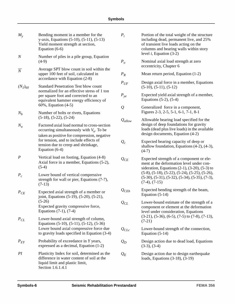
Symbols
My Bending moment in a member for the y-axis, Equations (5-10), (5-11), (5-13)Yield moment strength at section, Equation (6-6)
N Number of piles in a pile group, Equation (4-9)
—N Average SPT blow count in soil within the
upper 100 feet of soil, calculated in accordance with Equation (2-8)
(N1)60 Standard Penetration Test blow count normalized for an effective stress of 1 ton per square foot and corrected to an equivalent hammer energy efficiency of 60%, Equation (4-5)
Nb Number of bolts or rivets, Equations (5-18), (5-22), (5-24)
Nu Factored axial load normal to cross-section occurring simultaneously with Vu. To be taken as positive for compression, negative for tension, and to include effects of tension due to creep and shrinkage, Equation (6-4)
P Vertical load on footing, Equation (4-8)Axial force in a member, Equations (5-2), (5-4)
Pc Lower bound of vertical compressive strength for wall or pier, Equations (7-7), (7-13)
PCE Expected axial strength of a member or joint, Equations (5-19), (5-20), (5-21), (5-26)Expected gravity compressive force, Equations (7-1), (7-4)
PCL Lower-bound axial strength of column, Equations (5-10), (5-11), (5-12), (5-36)Lower bound axial compressive force due to gravity loads specified in Equation (3-4)
PEY Probability of exceedance in Y years, expressed as a decimal, Equation (1-2)
PI Plasticity Index for soil, determined as the difference in water content of soil at the liquid limit and plastic limit, Section 1.6.1.4.1
Pi Portion of the total weight of the structure including dead, permanent live, and 25% of transient live loads acting on the columns and bearing walls within story level i, Equation (3-2)
Po Nominal axial load strength at zero eccentricity, Chapter 6
PR Mean return period, Equation (1-2)
PUF Design axial force in a member, Equations (5-10), (5-11), (5-12)
Pye Expected yield axial strength of a member, Equations (5-2), (5-4)
Q Generalized force in a component, Figures 2-3, 2-5, 5-1, 6-1, 7-1, 8-1
Qallow Allowable bearing load specified for the design of deep foundations for gravity loads (dead plus live loads) in the available design documents, Equation (4-2)
Qc Expected bearing capacity of deep or shallow foundation, Equations (4-2), (4-3), (4-7)
QCE Expected strength of a component or ele-ment at the deformation level under con-sideration, Equations (2-1), (3-20), (5-3) to (5-8), (5-18), (5-22), (5-24), (5-25), (5-26), (5-30), (5-31), (5-32), (5-34), (5-35), (7-3), (7-4), (7-15)
QCEb Expected bending strength of the beam, Equation (5-14)
QCL Lower-bound estimate of the strength of a component or element at the deformation level under consideration, Equations (3-21), (5-36), (6-5), (7-5) to (7-8), (7-13), (7-21)
QCLc Lower-bound strength of the connection, Equation (5-14)
QD Design action due to dead load, Equations (3-3), (3-4)
QE Design action due to design earthequake loads, Equations (3-18), (3-19)
Symbols-6 Seismic Rehabilitation Prestandard FEMA 356
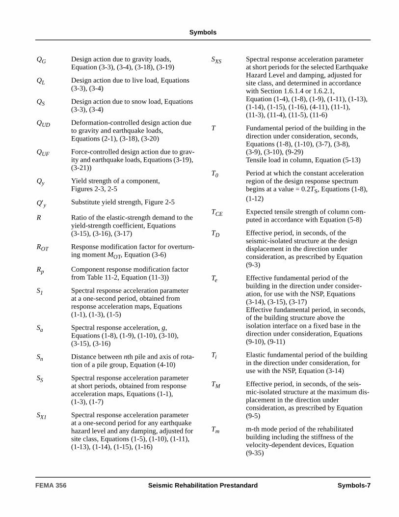
Symbols
QG Design action due to gravity loads, Equation (3-3), (3-4), (3-18), (3-19)
QL Design action due to live load, Equations (3-3), (3-4)
QS Design action due to snow load, Equations (3-3), (3-4)
QUD Deformation-controlled design action due to gravity and earthquake loads, Equations (2-1), (3-18), (3-20)
QUF Force-controlled design action due to grav-ity and earthquake loads, Equations (3-19), (3-21))
Qy Yield strength of a component, Figures 2-3, 2-5
Q′y Substitute yield strength, Figure 2-5
R Ratio of the elastic-strength demand to the yield-strength coefficient, Equations (3-15), (3-16), (3-17)
ROT Response modification factor for overturn-ing moment MOT, Equation (3-6)
Rp Component response modification factor from Table 11-2, Equation (11-3))
S1 Spectral response acceleration parameter at a one-second period, obtained from response acceleration maps, Equations (1-1), (1-3), (1-5)
Sa Spectral response acceleration, g, Equations (1-8), (1-9), (1-10), (3-10), (3-15), (3-16)
Sn Distance between nth pile and axis of rota-tion of a pile group, Equation (4-10)
SS Spectral response acceleration parameter at short periods, obtained from response acceleration maps, Equations (1-1), (1-3), (1-7)
SX1 Spectral response acceleration parameter at a one-second period for any earthquake hazard level and any damping, adjusted for site class, Equations (1-5), (1-10), (1-11), (1-13), (1-14), (1-15), (1-16)
SXS Spectral response acceleration parameter at short periods for the selected Earthquake Hazard Level and damping, adjusted for site class, and determined in accordance with Section 1.6.1.4 or 1.6.2.1, Equation (1-4), (1-8), (1-9), (1-11), (1-13), (1-14), (1-15), (1-16), (4-11), (11-1), (11-3), (11-4), (11-5), (11-6)
T Fundamental period of the building in the direction under consideration, seconds, Equations (1-8), (1-10), (3-7), (3-8), (3-9), (3-10), (9-29)Tensile load in column, Equation (5-13)
T0 Period at which the constant acceleration region of the design response spectrum begins at a value = 0.2TS, Equations (1-8), (1-12)
TCE Expected tensile strength of column com-puted in accordance with Equation (5-8)
TD Effective period, in seconds, of the seismic-isolated structure at the design displacement in the direction under consideration, as prescribed by Equation (9-3)
Te Effective fundamental period of the building in the direction under consider-ation, for use with the NSP, Equations (3-14), (3-15), (3-17)Effective fundamental period, in seconds, of the building structure above the isolation interface on a fixed base in the direction under consideration, Equations (9-10), (9-11)
Ti Elastic fundamental period of the building in the direction under consideration, for use with the NSP, Equation (3-14)
TM Effective period, in seconds, of the seis-mic-isolated structure at the maximum dis-placement in the direction under consideration, as prescribed by Equation (9-5)
Tm m-th mode period of the rehabilitated building including the stiffness of the velocity-dependent devices, Equation (9-35)
FEMA 356 Seismic Rehabilitation Prestandard Symbols-7
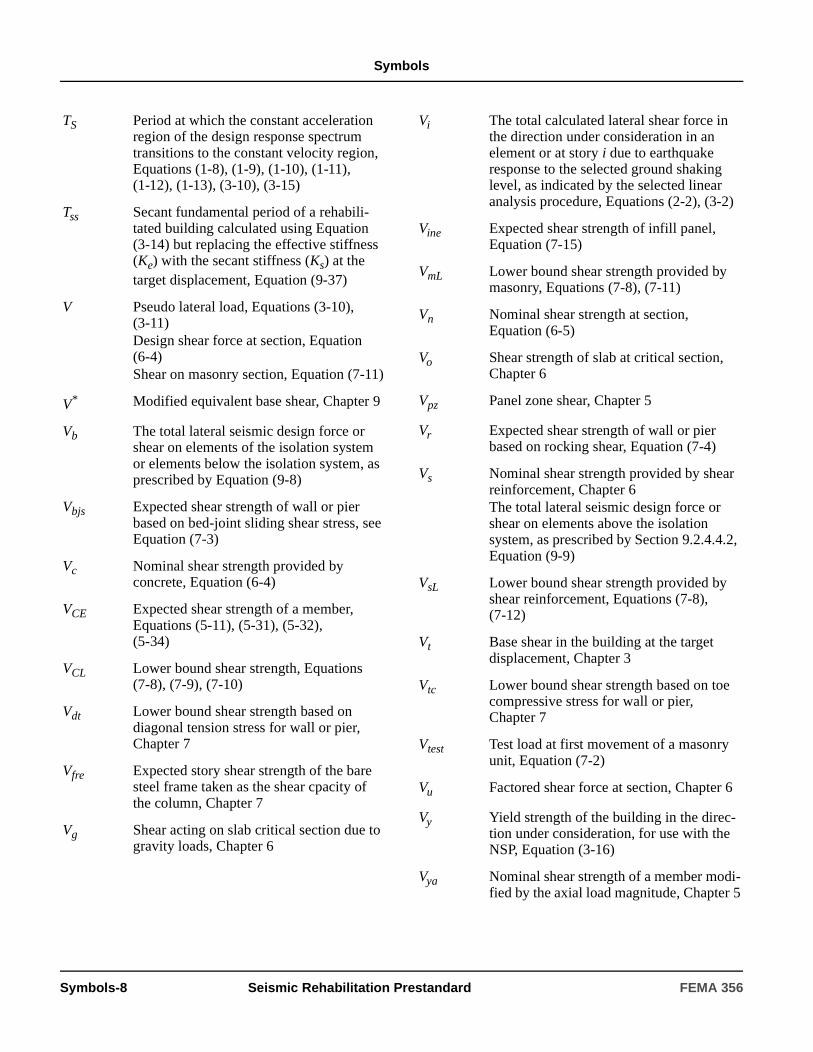
Symbols
TS Period at which the constant acceleration region of the design response spectrum transitions to the constant velocity region, Equations (1-8), (1-9), (1-10), (1-11), (1-12), (1-13), (3-10), (3-15)
Tss Secant fundamental period of a rehabili-tated building calculated using Equation (3-14) but replacing the effective stiffness (Ke) with the secant stiffness (Ks) at the target displacement, Equation (9-37)
V Pseudo lateral load, Equations (3-10), (3-11)Design shear force at section, Equation (6-4)Shear on masonry section, Equation (7-11)
V* Modified equivalent base shear, Chapter 9
Vb The total lateral seismic design force or shear on elements of the isolation system or elements below the isolation system, as prescribed by Equation (9-8)
Vbjs Expected shear strength of wall or pier based on bed-joint sliding shear stress, seeEquation (7-3)
Vc Nominal shear strength provided by concrete, Equation (6-4)
VCE Expected shear strength of a member, Equations (5-11), (5-31), (5-32), (5-34)
VCL Lower bound shear strength, Equations (7-8), (7-9), (7-10)
Vdt Lower bound shear strength based on diagonal tension stress for wall or pier, Chapter 7
Vfre Expected story shear strength of the bare steel frame taken as the shear cpacity of the column, Chapter 7
Vg Shear acting on slab critical section due to gravity loads, Chapter 6
Vi The total calculated lateral shear force in the direction under consideration in an element or at story i due to earthquake response to the selected ground shaking level, as indicated by the selected linear analysis procedure, Equations (2-2), (3-2)
Vine Expected shear strength of infill panel, Equation (7-15)
VmL Lower bound shear strength provided by masonry, Equations (7-8), (7-11)
Vn Nominal shear strength at section, Equation (6-5)
Vo Shear strength of slab at critical section, Chapter 6
Vpz Panel zone shear, Chapter 5
Vr Expected shear strength of wall or pier based on rocking shear, Equation (7-4)
Vs Nominal shear strength provided by shear reinforcement, Chapter 6The total lateral seismic design force or shear on elements above the isolation system, as prescribed by Section 9.2.4.4.2, Equation (9-9)
VsL Lower bound shear strength provided by shear reinforcement, Equations (7-8), (7-12)
Vt Base shear in the building at the target displacement, Chapter 3
Vtc Lower bound shear strength based on toe compressive stress for wall or pier, Chapter 7
Vtest Test load at first movement of a masonry unit, Equation (7-2)
Vu Factored shear force at section, Chapter 6
Vy Yield strength of the building in the direc-tion under consideration, for use with the NSP, Equation (3-16)
Vya Nominal shear strength of a member modi-fied by the axial load magnitude, Chapter 5
Symbols-8 Seismic Rehabilitation Prestandard FEMA 356
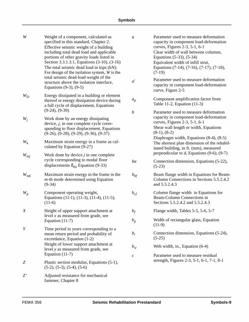
Symbols
W Weight of a component, calculated as specified in this standard, Chapter 2.Effective seismic weight of a building including total dead load and applicable portions of other gravity loads listed in Section 3.3.1.3.1, Equations (3-10), (3-16)The total seismic dead load in kips (kN). For design of the isolation system, W is the total seismic dead-load weight of the structure above the isolation interface, Equations (9-3), (9-5)
WD Energy dissipated in a building or element thereof or energy dissipation device during a full cycle of displacement, Equations (9-24), (9-39)
Wj Work done by an energy dissipating device, j, in one complete cycle corre-sponding to floor displacement, Equations (9-26), (9-28), (9-29), (9-36), (9-37)
Wk Maximum strain energy in a frame as cal-culated by Equation (9-27)
Wmj Work done by device j in one complete cycle corresponding to modal floor displacements δmi Equation (9-33)
Wmk Maximum strain energy in the frame in the m-th mode determined using Equation (9-34)
Wp Component operating weight, Equations (11-1), (11-3), (11-4), (11-5), (11-6)
X Height of upper support attachment at level x as measured from grade, seeEquation (11-7)
Y Time period in years corresponding to a mean return period and probability of exceedance, Equation (1-2)Height of lower support attachment at level y as measured from grade, seeEquation (11-7)
Z Plastic section modulus, Equations (5-1), (5-2), (5-3), (5-4), (5-6)
Z’ Adjusted resistance for mechanical fastener, Chapter 8
a Parameter used to measure deformation capacity in component load-deformation curves, Figures 2-3, 5-1, 6-1Clear width of wall between columns, Equations (5-33), (5-34)Equivalent width of infill strut, Equations (7-14), (7-16), (7-17), (7-18), (7-19)
a′ Parameter used to measure deformation capacity in component load-deformation curve, Figure 2-5
ap Component amplification factor from Table 11-2, Equation (11-3)
b Parameter used to measure deformation capacity in component load-deformation curves, Figures 2-3, 5-1, 6-1Shear wall length or width, Equations (8-1), (8-2)Diaphragm width, Equations (8-4), (8-5)The shortest plan dimension of the rehabil-itated building, in ft. (mm), measured perpendicular to d, Equations (9-6), (9-7)
ba Connection dimension, Equations (5-22), (5-23)
bbf Beam flange width in Equations for Beam-Column Connections in Sections 5.5.2.4.2 and 5.5.2.4.3
bcf Column flange width in Equations for Beam-Column Connections in Sections 5.5.2.4.2 and 5.5.2.4.3
bf Flange width, Tables 5-5, 5-6, 5-7
bp Width of rectangular glass, Equation (11-9)
bt Connection dimension, Equations (5-24), (5-25)
bw Web width, in., Equation (6-4)
c Parameter used to measure residual strength, Figures 2-3, 5-1, 6-1, 7-1, 8-1
FEMA 356 Seismic Rehabilitation Prestandard Symbols-9
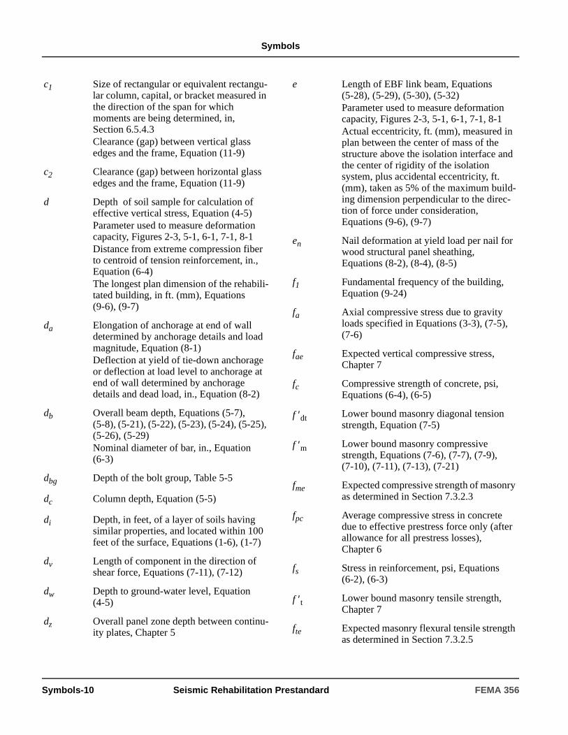
Symbols
c1 Size of rectangular or equivalent rectangu-lar column, capital, or bracket measured in the direction of the span for which moments are being determined, in, Section 6.5.4.3Clearance (gap) between vertical glass edges and the frame, Equation (11-9)
c2 Clearance (gap) between horizontal glass edges and the frame, Equation (11-9)
d Depth of soil sample for calculation of effective vertical stress, Equation (4-5)Parameter used to measure deformation capacity, Figures 2-3, 5-1, 6-1, 7-1, 8-1Distance from extreme compression fiber to centroid of tension reinforcement, in., Equation (6-4)The longest plan dimension of the rehabili-tated building, in ft. (mm), Equations (9-6), (9-7)
da Elongation of anchorage at end of wall determined by anchorage details and load magnitude, Equation (8-1)Deflection at yield of tie-down anchorage or deflection at load level to anchorage at end of wall determined by anchorage details and dead load, in., Equation (8-2)
db Overall beam depth, Equations (5-7), (5-8), (5-21), (5-22), (5-23), (5-24), (5-25), (5-26), (5-29)Nominal diameter of bar, in., Equation (6-3)
dbg Depth of the bolt group, Table 5-5
dc Column depth, Equation (5-5)
di Depth, in feet, of a layer of soils having similar properties, and located within 100 feet of the surface, Equations (1-6), (1-7)
dv Length of component in the direction of shear force, Equations (7-11), (7-12)
dw Depth to ground-water level, Equation (4-5)
dz Overall panel zone depth between continu-ity plates, Chapter 5
e Length of EBF link beam, Equations (5-28), (5-29), (5-30), (5-32)Parameter used to measure deformation capacity, Figures 2-3, 5-1, 6-1, 7-1, 8-1Actual eccentricity, ft. (mm), measured in plan between the center of mass of the structure above the isolation interface and the center of rigidity of the isolation system, plus accidental eccentricity, ft. (mm), taken as 5% of the maximum build-ing dimension perpendicular to the direc-tion of force under consideration, Equations (9-6), (9-7)
en Nail deformation at yield load per nail for wood structural panel sheathing, Equations (8-2), (8-4), (8-5)
f1 Fundamental frequency of the building, Equation (9-24)
fa Axial compressive stress due to gravity loads specified in Equations (3-3), (7-5), (7-6)
fae Expected vertical compressive stress, Chapter 7
fc Compressive strength of concrete, psi, Equations (6-4), (6-5)
f ′dt Lower bound masonry diagonal tension strength, Equation (7-5)
f ′m Lower bound masonry compressive strength, Equations (7-6), (7-7), (7-9), (7-10), (7-11), (7-13), (7-21)
fme Expected compressive strength of masonry as determined in Section 7.3.2.3
fpc Average compressive stress in concrete due to effective prestress force only (after allowance for all prestress losses), Chapter 6
fs Stress in reinforcement, psi, Equations (6-2), (6-3)
f ′t Lower bound masonry tensile strength, Chapter 7
fte Expected masonry flexural tensile strength as determined in Section 7.3.2.5
Symbols-10 Seismic Rehabilitation Prestandard FEMA 356

Symbols
fvie Expected shear strength of masonry infill, Equation (7-15)
fy Yield strength of tension reinforcement, Equations (6-2), (6-3)Lower bound of yield strength of reinforc-ing steel, Equations (7-12), (7-13)
fye Expected yield strength of reinforcing steel as determined in Section 7.3.2.8
g Acceleration of gravity (386.1 in./sec.2, or 9,807 mm/sec2 for SI units), Equations (3-15), (9-2), (9-3), (9-4), (9-5), (9-30)
h Average story height above and below a beam-column joint, Equation (5-17)Clear height of wall between beams, Equations (5-33), (5-35)Distance from inside of compression flange to inside of tension flange, Equation (5-7)Height of member along which deforma-tions are measured, Chapter 6Overall thickness of member, in, Equation (6-4)Height of a column, pilaster, or wall, Chapter 7Shear wall height, Equations (8-1), (8-2)Average roof elevation of structure, relative to grade elevation, Equation (11-3)
hc Assumed web depth for stability, Chapter 5Gross cross-sectional dimension of column core measured in the direction of joint shear, in, Chapter 6
hcol Height of column between beam center-lines, Equation (7-14)
heff Effective height of wall or pier compo-nents under consideration, Equations (7-4), (7-5), (7-6)
hi Height from the base of a building to floor level i, Equations (3-12), (9-9)Height of story i between two floors at common points of reference, Equation (3-2)
hinf Height of infill panel, Equations (7-14), (7-17), (7-19), (7-20), (7-21)
hn Height to roof level, ft, Equation (3-7)
hp Height of rectangular glass, Equation (11-9)
hx Height from base to floor level x, ft, Equations (3-12), (9-9)
k Exponent used for determining the vertical distribution of lateral forces, Equation (3-12)Coefficient used for calculation of column shear strength, Chapter 6
k1 Distance from the center of the split tee stem to the edge of the split tee flange fil-let, Equation (5-25)
keff Effective stiffness of an isolator unit, as prescribed by Equation (9-12), or an energy dissipation unit, as prescribed by Equations (9-23) or (9-38)
kh Horizontal seismic coefficient in soil act-ing on retaining wall, Equation (4-11)
ksr Winkler spring stiffness in overturning (rotation) for pile group, expressed as moment/unit rotation, Equation (4-10)
ksv Winkler spring stiffness in vertical direc-tion, expressed as force/unit displacement/unit area, Equation (4-6) Pile group axial spring stiffness expressed as force/unit displacement, Equation (4-9)
kv Shear buckling coefficient, Chapter 5
kvn Axial stiffness of nth pile in a pile group, Equation (4-10)
lb Length of beam, Equation (5-1)Provided length of straight development, lap splice, or standard hook, in., Equation (6-2)
lbeff Assumed distance to infill strut reaction point for beams, Equation (7-18)
lc Length of column, Equations (5-2), (5-36)
lceff Assumed distance to infill strut reaction point for columns, Equation (7-16)
FEMA 356 Seismic Rehabilitation Prestandard Symbols-11
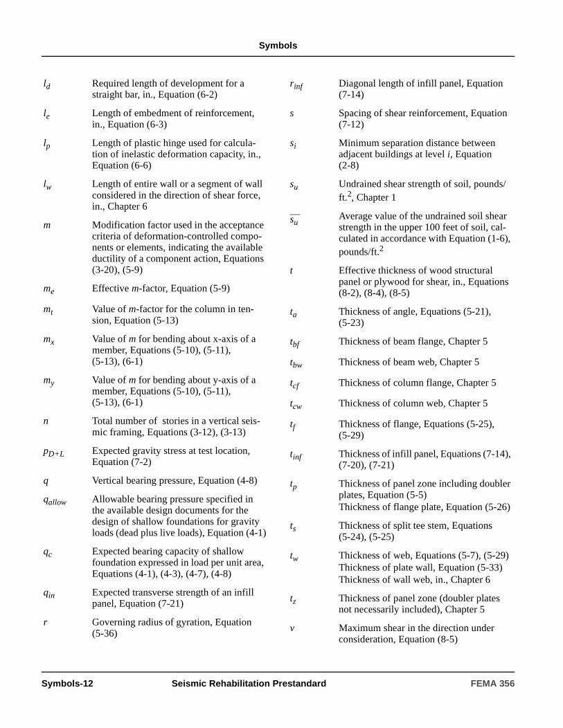
Symbols
ld Required length of development for a straight bar, in., Equation (6-2)
le Length of embedment of reinforcement, in., Equation (6-3)
lp Length of plastic hinge used for calcula-tion of inelastic deformation capacity, in., Equation (6-6)
lw Length of entire wall or a segment of wall considered in the direction of shear force, in., Chapter 6
m Modification factor used in the acceptance criteria of deformation-controlled compo-nents or elements, indicating the available ductility of a component action, Equations (3-20), (5-9)
me Effective m-factor, Equation (5-9)
mt Value of m-factor for the column in ten-sion, Equation (5-13)
mx Value of m for bending about x-axis of a member, Equations (5-10), (5-11), (5-13), (6-1)
my Value of m for bending about y-axis of a member, Equations (5-10), (5-11), (5-13), (6-1)
n Total number of stories in a vertical seis-mic framing, Equations (3-12), (3-13)
pD+L Expected gravity stress at test location, Equation (7-2)
q Vertical bearing pressure, Equation (4-8)
qallow Allowable bearing pressure specified in the available design documents for the design of shallow foundations for gravity loads (dead plus live loads), Equation (4-1)
qc Expected bearing capacity of shallow foundation expressed in load per unit area, Equations (4-1), (4-3), (4-7), (4-8)
qin Expected transverse strength of an infill panel, Equation (7-21)
r Governing radius of gyration, Equation (5-36)
rinf Diagonal length of infill panel, Equation (7-14)
s Spacing of shear reinforcement, Equation (7-12)
si Minimum separation distance between adjacent buildings at level i, Equation (2-8)
su Undrained shear strength of soil, pounds/ft.2, Chapter 1
—suAverage value of the undrained soil shear strength in the upper 100 feet of soil, cal-culated in accordance with Equation (1-6), pounds/ft.2
t Effective thickness of wood structural panel or plywood for shear, in., Equations (8-2), (8-4), (8-5)
ta Thickness of angle, Equations (5-21), (5-23)
tbf Thickness of beam flange, Chapter 5
tbw Thickness of beam web, Chapter 5
tcf Thickness of column flange, Chapter 5
tcw Thickness of column web, Chapter 5
tf Thickness of flange, Equations (5-25), (5-29)
tinf Thickness of infill panel, Equations (7-14), (7-20), (7-21)
tp Thickness of panel zone including doubler plates, Equation (5-5)Thickness of flange plate, Equation (5-26)
ts Thickness of split tee stem, Equations (5-24), (5-25)
tw Thickness of web, Equations (5-7), (5-29)Thickness of plate wall, Equation (5-33)Thickness of wall web, in., Chapter 6
tz Thickness of panel zone (doubler plates not necessarily included), Chapter 5
v Maximum shear in the direction under consideration, Equation (8-5)
Symbols-12 Seismic Rehabilitation Prestandard FEMA 356

Symbols
vme Expected masonry shear strength, Equation (7-1)Expected masonry bed-joint sliding shear strength, Equation (7-3)
vte Average bed-joint shear strength, Equation (7-1)
vto Bed-joint shear stress from single test, Equation (7-2)
vy Shear at yield in the direction under consideration in lb./ft., Equations (8-1), (8-2), (8-3), (8-4), (8-5)
w Water content of soil, calculated as the ratio of the weight of water in a unit volume of soil to the weight of soil in the unit volume, expressed as a percentage, Section 1.6.1.4.1Length of connection member, seeEquations (5-23), (5-25)
wi Portion of the effective seismic weight corresponding to floor level i, Equations (3-12), (3-13), (9-9)
wx Portion of the effective seismic weight corresponding to floor level x, Equations (3-12), (3-13), (9-9)
wz Width of panel zone between column flanges, Chapter 5
x Elevation in structure of component relative to grade elevation, Equation (11-3)
y The distance, in ft. (mm), between the center of rigidity of the isolation system rigidity and the element of interest, measured perpendicular to the direction of seismic loading under consideration, Equations (9-6), (9-7)
∆ Generalized deformation, Figures 2-3, 2-5, 5-1, 6-1, 8-1Total elastic and plastic displacement, Chapter 5Calculated deflection of diaphragm, wall, or bracing element, in.
∆− Negative displacement amplitude, in. (mm), of an isolator or energy dissipation unit during a cycle of prototype testing, Equations (9-12), (9-13), (9-38)
∆+ Positive displacement amplitude, in. (mm), of an isolator or energy dissipation unit during a cycle of prototype testing,Equations (9-12), (9-13), (9-38)
∆ave Average displacement of an energy dissi-pation unit during a cycle of prototype
testing, equal to (|∆+| + |∆−|)/2, Equation (9-39)
∆d Diaphragm deformation, Equations (3-8), (3-9)
∆eff Differentiated displacement between the top and bottom of the wall or pier compo-nents under consideration over a height, heff, Figure 7-1
∆fallout Relative seismic displacement (drift) causing glass fallout from the curtain wall, storefront, or partition, as determined in accordance with an approved engineering analysis method, Equations (11-10), (11-11)
∆i Inter-story displacement (drift) of story i divided by the story height, Chapter 5
∆i1 Estimated lateral deflection of building 1 relative to the ground at level i, Equation (2-8)
∆i2 Estimated lateral deflection of building 2 relative to the ground at level i, Equation (2-8)
∆inf Deflection of infill panel at mid-length when subjected to transverse loads, Equation (7-20)
∆p Additional earth pressure on retaining wall due to earthquake shaking, Equation (4-11)
∆w Average in-plane wall displacement, Equation (3-8)
FEMA 356 Seismic Rehabilitation Prestandard Symbols-13
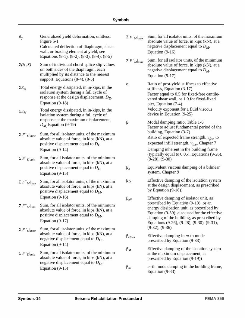
Symbols
∆y Generalized yield deformation, unitless, Figure 5-1Calculated deflection of diaphragm, shear wall, or bracing element at yield, seeEquations (8-1), (8-2), (8-3), (8-4), (8-5)
Σ(∆ cX) Sum of individual chord-splice slip values on both sides of the diaphragm, each multiplied by its distance to the nearest support, Equations (8-4), (8-5)
ΣED Total energy dissipated, in in-kips, in the isolation system during a full cycle of response at the design displacement, DD, Equation (9-18)
ΣEMTotal energy dissipated, in in-kips, in the isolation system during a full cycle of response at the maximum displacement, DM, Equation (9-19)
Σ|F+D|max Sum, for all isolator units, of the maximum
absolute value of force, in kips (kN), at a positive displacement equal to DD, Equation (9-14)
Σ|F+D|min Sum, for all isolator units, of the minimum
absolute value of force, in kips (kN), at a positive displacement equal to DD,Equation (9-15)
Σ|F+M|max Sum, for all isolator units, of the maximum
absolute value of force, in kips (kN), at a positive displacement equal to DM, Equation (9-16)
Σ|F+M|min Sum, for all isolator units, of the minimum
absolute value of force, in kips (kN), at a positive displacement equal to DM, Equation (9-17)
Σ|F -D|max Sum, for all isolator units, of the maximum absolute value of force, in kips (kN), at a negative displacement equal to DD, Equation (9-14)
Σ|F -D|min Sum, for all isolator units, of the minimum absolute value of force, in kips (kN), at a negative displacement equal to DD, Equation (9-15)
Σ|F -M|max Sum, for all isolator units, of the maximum
absolute value of force, in kips (kN), at a negative displacement equal to DM, Equation (9-16)
Σ|F -M|min Sum, for all isolator units, of the minimum absolute value of force, in kips (kN), at a negative displacement equal to DM, Equation (9-17)
α Ratio of post-yield stiffness to effective stiffness, Equation (3-17)Factor equal to 0.5 for fixed-free cantile-vered shear wall, or 1.0 for fixed-fixed pier, Equation (7-4)Velocity exponent for a fluid viscous device in Equation (9-25)
β Modal damping ratio, Table 1-6Factor to adjust fundamental period of the building, Equation (3-7)Ratio of expected frame strength, vfre, to expected infill strength, vine, Chapter 7
Damping inherent in the building frame (typically equal to 0.05), Equations (9-26), (9-28), (9-30)
βb Equivalent viscous damping of a bilinear system, Chapter 9
βD Effective damping of the isolation system at the design displacement, as prescribed by Equation (9-18))
βeff Effective damping of isolator unit, as prescribed by Equation (9-13), or an energy dissipation unit, as prescribed by Equation (9-39); also used for the effective damping of the building, as prescribed by Equations (9-26), (9-28), (9-30), (9-31), (9-32), (9-36)
βeff-m Effective damping in m-th mode prescribed by Equation (9-33)
βM Effective damping of the isolation system at the maximum displacement, as prescribed by Equation (9-19))
βm m-th mode damping in the building frame, Equation (9-33)
Symbols-14 Seismic Rehabilitation Prestandard FEMA 356
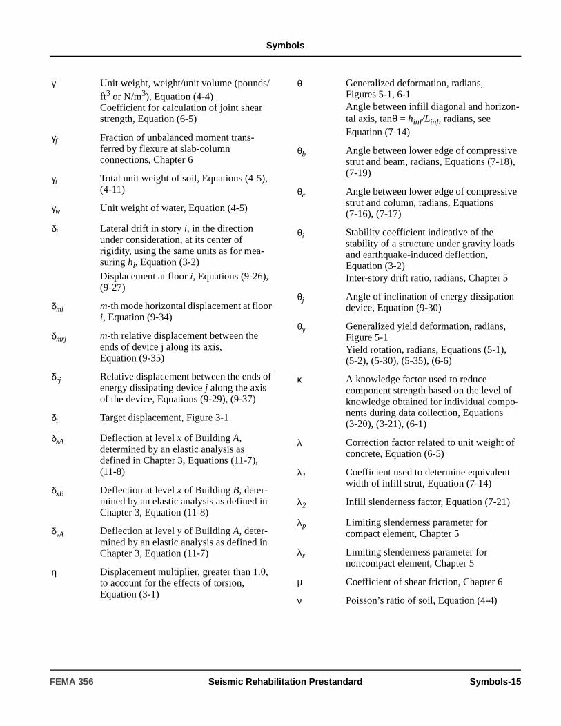
Symbols
γ Unit weight, weight/unit volume (pounds/ft3 or N/m3), Equation (4-4)Coefficient for calculation of joint shear strength, Equation (6-5)
γf Fraction of unbalanced moment trans-ferred by flexure at slab-column connections, Chapter 6
γt Total unit weight of soil, Equations (4-5), (4-11)
γw Unit weight of water, Equation (4-5)
δi Lateral drift in story i, in the direction under consideration, at its center of rigidity, using the same units as for mea-suring hi, Equation (3-2)
Displacement at floor i, Equations (9-26), (9-27)
δmi m-th mode horizontal displacement at floor i, Equation (9-34)
δmrj m-th relative displacement between the ends of device j along its axis, Equation (9-35)
δrj Relative displacement between the ends of energy dissipating device j along the axis of the device, Equations (9-29), (9-37)
δt Target displacement, Figure 3-1
δxA Deflection at level x of Building A, determined by an elastic analysis as defined in Chapter 3, Equations (11-7), (11-8)
δxB Deflection at level x of Building B, deter-mined by an elastic analysis as defined in Chapter 3, Equation (11-8)
δyA Deflection at level y of Building A, deter-mined by an elastic analysis as defined in Chapter 3, Equation (11-7)
η Displacement multiplier, greater than 1.0, to account for the effects of torsion, Equation (3-1)
θ Generalized deformation, radians, Figures 5-1, 6-1Angle between infill diagonal and horizon-tal axis, tanθ = hinf/Linf, radians, seeEquation (7-14)
θb Angle between lower edge of compressive strut and beam, radians, Equations (7-18), (7-19)
θc Angle between lower edge of compressive strut and column, radians, Equations (7-16), (7-17)
θi Stability coefficient indicative of the stability of a structure under gravity loads and earthquake-induced deflection,Equation (3-2)Inter-story drift ratio, radians, Chapter 5
θj Angle of inclination of energy dissipation device, Equation (9-30)
θy Generalized yield deformation, radians, Figure 5-1Yield rotation, radians, Equations (5-1), (5-2), (5-30), (5-35), (6-6)
κ A knowledge factor used to reduce component strength based on the level of knowledge obtained for individual compo-nents during data collection, Equations (3-20), (3-21), (6-1)
λ Correction factor related to unit weight of concrete, Equation (6-5)
λ1 Coefficient used to determine equivalent width of infill strut, Equation (7-14)
λ2 Infill slenderness factor, Equation (7-21)
λp Limiting slenderness parameter for compact element, Chapter 5
λr Limiting slenderness parameter for noncompact element, Chapter 5
µ Coefficient of shear friction, Chapter 6
ν Poisson’s ratio of soil, Equation (4-4)
FEMA 356 Seismic Rehabilitation Prestandard Symbols-15
Symbols
νs Shear wave velocity in soil, in feet/sec., Section 1.6.1.4.1Shear wave velocity at low strains, Equation (4-4)
__vs
Average value of the soil shear wave velocity in the upper 100 feet of soil, calculated in accordance with Equation (1-6), feet/sec.
ρ Ratio of non-prestressed tension reinforce-ment, Chapter 6
ρbal Reinforcement ratio producing balanced strain conditions, Chapter 6
ρg Ratio of area of total wall or pier vertical plus horizontal reinforcement to area of wall or pier cross-section, Chapter 7
ρlp Yield deformation of a link beam, Chapter 5
ρn Ratio of distributed shear reinforcement in a plane perpendicular to the direction of the applied shear, Chapter 6
ρ′ Ratio of non-prestressed compression reinforcement, Chapter 6
ρ′′ Reinforcement ratio for transverse joint reinforcement, Chapter 6
σ Standard deviation of the variation of the material strengths, Chapter 2
σ′o Effective vertical stress, Equation (4-5)
φ Strength reduction factor
φi Modal displacement of floor i, seeEquation (9-30)
φrj Relative modal displacement in horizontal direction of energy dissipation device j, Equation (9-30)
χ A factor to calculate horizontal seismic force, Fp, Equations (2-6), (2-7)
ω1 Fundamental angular frequency equal to 2πf1, Equation (9-24)
Symbols-16 Seismic Rehabilitation Prestandard FEMA 356
Acronyms
Acronyms
AAMA American Architectural Manufacturers Association
ABK Agbabian, Barnes and Kariotis joint ven-ture
ACI American Concrete Institute
AISC American Institute of Steel Construction
AISI American Iron and Steel Institute
ANSI American National Standards Institute
APA American Plywood Association
API American Petroleum Institute
ASCE American Society of Civil Engineers
ASHRAE American Society of Heating, Refrigera-tion and Air Conditioning Engineers
ASME American Society of Mechanical Engi-neers
ASTM American Society for Testing and Materi-als
ATC Applied Technology Council
AWS American Welding Society
AWWA American Water Works Association
BNC Ball and cone system, a rolling seismic isolator
BOCA Building Officials and Code Administra-tors
BRANZ Building Research Association of New Zealand
BSE-1 Basic Safety Earthquake-1
BSE-2 Basic Safety Earthquake-2
BSO Basic Safety Objective
BSSC Building Seismic Safety Council
CBF Concentric Braced Frame
CISCA Ceilings and Interior Systems Construc-tion Association
CP Collapse Prevention
CQC Complete Quadratic Combination
CRSI Concrete Reinforcing Steel Institute
CUREE California Universities for Research in Earthquake Engineering
CUSEC Central United States Earthquake Consor-tium
DCR Demand Capacity Ratio
DDS Double Diagonal Sheathing
EBF Eccentric Braced Frame
EDD Energy Dissipation Device
EDS Energy Dissipation System
EERC Earthquake Engineering Research Center
EERI Earthquake Engineering Research Insti-tute
FEMA Federal Emergency Management Agency
FPS Friction-pendulum system, a sliding seis-mic isolator
FR Fully Restrained
GFRC Glass Fiber Reinforced Concrete
HDR High-damping rubber bearings, an elasto-meric seismic isolator
HR Hazards Reduced
HVAC Heating, ventilation, and air conditioning
IBC International Building Code
ICBO International Conference of Building Offi-cials
IO Immediate Occupancy
LDP Linear Dynamic Procedure
LRB Low-damping rubber bearings with a lead core, an elastomeric seismic isolator
LRFD Load and Resistance Factor Design
LS Life Safety
FEMA 356 Seismic Rehabilitation Prestandard Acronyms-1

Acronyms
LSP Linear Static Procedure
MCE Maximum Considered Earthquake
MDOF Multi-degree of Freedom System
MEP Mechanical, electrical, and plumbing
MSJC Masonry Standards Joint Committee
NAVFAC Publication of the U.S. Department of the Navy
NBS National Bureau of Standards
NCEER National Center for Earthquake Engineer-ing Research
NDE Nondestructive Examination
NDP Nonlinear Dynamic Procedure
NDS National Design Specification
NEHRP National Earthquake Hazard Reduction Program
NFPA National Fire Protection Association
NIST National Institute of Standards and Tech-nology (formerly NBS)
NSP Nonlinear Static Procedure
OMF Ordinary Moment Frame
PCI Precast Concrete Institute
PR Partially Restrained
PS-# Product Standard-#
QAP Quality Assurance Plan
RB Low-damping rubber bearings, an elasto-meric seismic isolator
RM Reinforced Masonry
SAC SEAOC, ATC and CUREe joint ventures
SBC Southern Building Code
SBCCI Southern Building Code Congress, Inter-national
SDI Steel Deck Institute
SDOF Single-degree of Freedom
SEAOC Structural Engineers Association of Cali-fornia
SJI Steel Joist Institute
SMACNA Sheet Metal and Air Conditioning Con-tractors National Association
SMF Special Moment Frame
SPT Standard Penetration Test
SSI Soil-structure interaction
TMS The Masonry Society
UBC Uniform Building Code
UCBC Uniform Code for Building Conservation
URM Unreinforced Masonry
USGS United States Geological Survey
WWPA Western Wood Products Association
Acronyms-2 Seismic Rehabilitation Prestandard FEMA 356
Definitions
Definitions
AAcceleration-sensitive nonstructural compo-nent: A nonstructural component that is sensitive to,and subject to, damage from inertial loading.
Acceptance criteria: Limiting values of propertiessuch as drift, strength demand, and inelastic deformationused to determine the acceptability of a component at agiven performance level.
Action: An internal moment, shear, torque, axial load,deformation, displacement, or rotation corresponding toa displacement due to a structural degree of freedom;designated as force- or deformation-controlled.
Active Fault: A fault for which there is an average his-toric slip rate of 1 mm per year or more, and evidence ofseismic activity within Holocene times (past 11,000years).
Adjusted Resistance: The reference resistanceadjusted to include the effects of applicable adjustmentfactors resulting from end use and other modifying fac-tors excluding time-effect adjustments, which are con-sidered separately and not included.
Aspect ratio: Ratio of height to width for shear wallsand span to width for horizontal diaphragms.
Assembly: Two or more interconnected components.
BBalloon framing: Continuous stud framing from sillto roof, with intervening floor joists nailed to studs andsupported by a let-in ribbon.
Base: The level at which earthquake effects areimparted to the building.
Beam: A structural member whose primary function isto carry loads transverse to its longitudinal axis.
Bearing wall: A wall that supports gravity loads of atleast 200 pounds per lineal foot from floors and/or roofs.
Bed joint: The horizontal layer of mortar on which amasonry unit is laid.
Boundary component (boundary member): Amember at the perimeter (edge or opening) of a shearwall or horizontal diaphragm that provides tensile and/orcompressive strength.
Braced frame: A vertical lateral-force-resisting ele-ment consisting of vertical, horizontal, and diagonalcomponents joined by concentric or eccentric connec-tions.
BSE-1: Basic Safety Earthquake-1, taken as the lesserof the ground shaking for a 10%/50 year earthquake ortwo-thirds of the BSE-2 at a site.
BSE-2: Basic Safety Earthquake-2, taken as the groundshaking based on the MCE at a site.
BSO: Basic Safety Objective is a Rehabilitation Objec-tive that achieves the dual rehabilitation goals of the LifeSafety Building Performance Level for the BSE-1 Earth-quake Hazard Level and the Collapse Prevention Build-ing Performance Level for the BSE-2 EarthquakeHazard Level.
Building Occupancy: The purpose for which a build-ing, or part thereof, is used, or intended to be used, des-ignated in accordance with the applicable building code.
Building Performance Level: A limiting damagestate for a building, considering structural and nonstruc-tural components, used in the definition of Rehabilita-tion Objectives.
CCast Iron: A hard, brittle nonmalleable iron-carbonalloy containing 2.0 to 4.5 percent carbon. Shapes areobtained by reducing iron ore in a blast furnace, formingit into bars (or pigs), and remelting and casting it into itsfinal form.
Cavity wall: A masonry wall with an air space betweenwythes.
Chord: See diaphragm chord.
Clay tile masonry: Masonry constructed with hollowunits made of clay tile.
FEMA 356 Seismic Rehabilitation Prestandard Definitions-1

Definitions
Clay-unit masonry: Masonry constructed with solid,cored, or hollow units made of clay; can be ungrouted orgrouted.
Closed stirrups or ties: Transverse reinforcementdefined in Chapter 7 of ACI 318 consisting of standardstirrups or ties with 90-degree hooks and lap splices in apattern that encloses longitudinal reinforcement.
Code Official: The organization, political subdivision,office, or individual legally charged with responsibilityfor administering and enforcing the provisions of thisstandard.
Coefficient of variation: For a sample of data, theratio of the standard deviation for the sample to the meanvalue for the sample.
Collar joint: Vertical longitudinal joint betweenwythes of masonry or between masonry wythe and back-up construction; can be filled with mortar or grout.
Collector: See drag strut.
Column (or beam) jacketing: A rehabilitation method inwhich a concrete column or beam is encased in a steel orconcrete “jacket” to strengthen and/or repair the memberby confining the concrete.
Component, flexible: A component, includingattachments, having a fundamental period greater than0.06 seconds.
Component, rigid: A component, including attach-ments, having a fundamental period less than or equal to0.06 seconds.
Components: The basic structural members that con-stitute a building, including beams, columns, slabs,braces, walls, piers, coupling beams, and connections;designated as primary or secondary.
Composite masonry wall: Multi-wythe masonrywall acting with composite action.
Composite panel: A structural panel comprising thinwood strands or wafers bonded together with exterioradhesive.
Concentric Braced Frame: Braced frame element inwhich component worklines intersect at a single point orat multiple points such that the distance between inter-secting components, or eccentricity, is less than or equal
to the width of the smallest member connected at thejoint.
Concrete masonry: Masonry constructed with solidor hollow units made of concrete; can be ungrouted orgrouted.
Condition of service: The environment to which thestructure will be subjected.
Connection: A link that transmits actions from onecomponent or element to another component or element,categorized by type of action (moment, shear, or axial).
Connection hardware: Proprietary or custom fabri-cated body of a component that is used to link woodcomponents.
Connectors: Nails, screws, lags, bolts, split rings, andshear plates used to link wood components to otherwood or metal components.
Contents: Movable items within the building intro-duced by the owner or occupants, weighing 400 poundsor more.
Continuity plates: Column stiffeners at the top andbottom of a panel zone.
Control node: A node located at the center of mass atthe roof of a building used in the NSP to measure theeffects of earthquake shaking on a building.
Corrective measure: Any modification of a compo-nent or element, or the structure as a whole, imple-mented to improve building performance.
Coupling beam: A component that ties or couplesadjacent shear walls acting in the same plane.
Cripple studs: Short studs between a header and topplate at openings in wall framing, or studs between thebase and sill of an opening.
Cripple wall: Short wall between the foundation andfirst floor framing.
Critical action: The component action that reaches itselastic limit at the lowest level of lateral deflection orloading of the structure.
Cross tie: A component that spans the width of the dia-phragm and delivers out-of-plane wall forces over thefull depth of the diaphragm.
Definitions-2 Seismic Rehabilitation Prestandard FEMA 356

Definitions
DDecay: Decomposition of wood caused by action ofwood-destroying fungi. The term “dry rot” is used inter-changeably with decay.
Decking: Solid sawn lumber or glue-laminated deck-ing, nominally two to four inches thick and four inchesand wider. Decking shall be tongue-and-groove or con-nected at longitudinal joints with nails or metal clips.
Deep foundation: Driven piles made of steel, con-crete, or wood, or cast-in-place concrete piers or drilledshafts of concrete.
Deformation-sensitive nonstructural compo-nent: A nonstructural component that is sensitive todeformation imposed by the drift or deformation of thestructure, including deflection or deformation of dia-phragms.
Demand: The amount of force or deformation imposedon an element or component.
Design displacement: The design earthquake dis-placement of an isolation or energy dissipation system,or elements thereof, excluding additional displacementdue to actual and accidental torsion.
Design earthquake: A user-specified earthquake forthe design of an isolated building having ground shakingcriteria described in Chapter 2.
Design resistance (force or moment as appro-priate): Resistance provided by member or connection;the product of adjusted resistance, the resistance factor,and time effect factor.
Diagonal bracing: Inclined components designed tocarry axial load, enabling a structural frame to act as atruss to resist lateral forces.
Diaphragm: A horizontal (or nearly horizontal) struc-tural element used to distribute inertial lateral forces tovertical elements of the lateral-force-resisting system.
Diaphragm chord: A component provided to resisttension or compression at the edges of a diaphragm.
Diaphragm collector: A component provided totransfer lateral forces in the diaphragm to vertical ele-ments of the lateral-force-resisting system or to otherportions of the diaphragm.
Diaphragm ratio: See aspect ratio.
Diaphragm strut: See drag strut.
Differential compaction: An earthquake- inducedprocess in which soils become more compact and settlein a nonuniform manner across a site.
Dimensioned lumber: Lumber from nominal twothrough four inches thick and nominal two or moreinches wide.
Displacement-dependent energy dissipationdevices: Devices having mechanical properties suchthat the force in the device is related to the relative dis-placement in the device.
Displacement restraint system: Collection ofstructural components and elements that limit lateral dis-placement of seismically-isolated buildings during theBSE-2.
Dowel-bearing strength: The maximum compres-sion strength of wood or wood-based products whensubjected to bearing by a steel dowel or bolt of specificdiameter.
Dowel type fasteners: Bolts, lag screws, woodscrews, nails, and spikes.
Drag strut: A component parallel to the applied loadthat collects and transfers diaphragm shear forces to thevertical lateral-force-resisting elements, or other por-tions of the diaphragm. Also called collector, diaphragmstrut, or tie.
Dressed size: The dimensions of lumber after surfac-ing with a planing machine.
Dry rot: See Decay.
Dry service: Structures wherein the maximum equilib-rium moisture content does not exceed 19%.
Dual system: A structural system with the followingfeatures:
1. A space frame included to support gravity loads withor without capability of resisting lateral loads.
2. Lateral-load-resisting system included to resist at least25% of the lateral loads provided by one or more of thefollowing: concrete or steel shear walls, steel eccentri-cally braced frames (EBF), concentrically braced frames(CBF), and moment-resisting frames (Special MomentFrames, or Ordinary Moment Frames).
3. Each system designed to resist the total lateral load inproportion to relative rigidity.
FEMA 356 Seismic Rehabilitation Prestandard Definitions-3

Definitions
EEarthquake Hazard Level: Ground shakingdemands of specified severity, developed on either aprobabilistic or deterministic basis.
Eccentric Braced Frame: Braced frame element inwhich component worklines do not intersect at a singlepoint and the distance between the intersecting compo-nents, or eccentricity, exceeds the width of the smallestmember connecting at the joint.
Edge distance: The distance from the edge of themember to the center of the nearest fastener.
Effective damping: The value of equivalent viscousdamping corresponding to the energy dissipated by thebuilding, or element thereof, during a cycle of response.
Effective stiffness: The value of the lateral force inthe building, or an element thereof, divided by the corre-sponding lateral displacement.
Effective Void Ratio: Ratio of collar joint area with-out mortar to the total area of the collar joint.
Element: An assembly of structural components thatact together in resisting forces, including gravity frames,moment-resisting frames, braced frames, shear walls,and diaphragms.
Energy dissipation device: Non-gravity-load-sup-porting element designed to dissipate energy in a stablemanner during repeated cycles of earthquake demand.
Energy dissipation system: Complete collection ofall energy dissipation devices, their supporting framing,and connections.
Expected Strength: The mean value of resistance ofa component at the deformation level anticipated for apopulation of similar components, including consider-ation of the variability in yield strength as well as strainhardening and plastic section development.
FFair Condition: Masonry found during conditionassessment to have mortar and units intact but withminor cracking.
Fault: Plane or zone along which earth materials onopposite sides have moved differentially in response totectonic forces.
Flexible connection: A link between componentsthat permits rotational and/or translational movementwithout degradation of performance, including universaljoints, bellows expansion joints, and flexible metal hose.
Flexible diaphragm: A diaphragm with horizontaldeformation along its length more than twice the averageinterstory drift.
Foundation system: An assembly of structural com-ponents, located at the soil-structure interface, that trans-fer loads from the superstructure into the supporting soil.
Fundamental period: The highest natural period ofthe building in the direction under consideration.
GGauge or row spacing: The center-to-center dis-tance between fastener rows or gauge lines.
Glulam beam: Shortened term for glue-laminatedbeam, which is a wood-based component made up oflayers of wood bonded with adhesive.
Good Condition: Masonry found during conditionassessment to have mortar and units intact and no visiblecracking.
Grade: The classification of lumber with regard tostrength and utility, in accordance with the grading rulesof an approved agency.
Grading rules: Systematic and standardized criteriafor rating the quality of wood products.
Gypsum wallboard or drywall: An interior wall sur-face sheathing material; can sometimes be consideredfor resisting lateral forces.
HHead joint: Vertical mortar joint placed betweenmasonry units in the same wythe.
Hold-down: Hardware used to anchor vertical chordforces in a shear wall to the foundation or framing of thestructure in order to resist the effects of overturning.
Definitions-4 Seismic Rehabilitation Prestandard FEMA 356
Definitions
Hollow masonry unit: A masonry unit with net cross-sectional area in every plane parallel to the bearing sur-face less than 75% of the gross cross-sectional area inthe same plane.
Hoops: Transverse reinforcement defined in Chapter21 of ACI 318 consisting of closed ties with 135-degreehooks embedded into the core and no lap splices.
IInfill: A panel of masonry placed within a steel or con-crete frame. Panels separated from the surroundingframe by a gap are termed “isolated infills.” Panels thatare in full contact with a frame around its full perimeterare termed “shear infills.”
In-plane wall: See shear wall.
Inter-story drift: The relative horizontal displacementof two adjacent floors in a building; can also beexpressed as a percentage of the story height separatingthe two adjacent floors.
Isolation interface: The boundary between the upperportion of the structure (superstructure), which is iso-lated, and the lower portion of the structure, whichmoves rigidly with the ground.
Isolation system: The collection of structural ele-ments that includes all individual isolator units, all struc-tural elements that transfer force between elements ofthe isolation system, and all connections to other struc-tural elements. The isolation system also includes thewind-restraint system, if such a system is used to meetthe design requirements of this section.
Isolator unit: A horizontally flexible and verticallystiff structural element of the isolation system that per-mits large lateral deformations under seismic load. Anisolator unit shall be used either as part of or in additionto the weight-supporting system of the building.
JJoint: An area where ends, surfaces, or edges of two ormore components are attached; categorized by type offastener or weld used and method of force transfer.
KKing stud: Full height studs adjacent to openings thatprovide out-of-plane stability to cripple studs at open-ings.
Knee Joint: A joint that in the direction of framing hasone column and one beam.
LLandslide: A down-slope mass movement of earthresulting from any cause.
Lateral support member: A member designed toinhibit lateral buckling or lateral-torsional buckling of acomponent.
Lateral-force-resisting system: Those elements ofthe structure that provide its basic lateral strength andstiffness.
Light framing: Repetitive framing with small, uni-formly spaced members.
Lightweight concrete: Structural concrete that hasan air-dry unit weight not exceeding 115 pcf.
Link beam: A component between points of eccentri-cally connected members in an eccentric braced frameelement.
Link intermediate web stiffeners: Vertical webstiffeners placed within a link.
Link rotation angle: Angle of plastic rotationbetween the link and the beam outside of the link,derived using the specified base shear, V.
Liquefaction: An earthquake-induced process inwhich saturated, loose, granular soils lose shear strengthand liquefy as a result of increase in pore-water pressureduring earthquake shaking.
Load and Resistance Factor Design: A method ofproportioning structural components (members, connec-tors, connecting elements, and assemblages) using loadfactors and strength reduction factors such that no appli-cable limit state is exceeded when the structure is sub-jected to all design load combinations.
Load duration: The period of continuous applicationof a given load, or the cumulative period of intermittentapplications of load. See time effect factor.
FEMA 356 Seismic Rehabilitation Prestandard Definitions-5
Definitions
Load path: A path through which seismic forces aredelivered from the point at which inertial forces are gen-erated in the structure to the foundation and, ultimately,the supporting soil.
Load sharing: The load redistribution mechanismamong parallel components constrained to deflecttogether.
Load/slip constant: The ratio of the applied load to aconnection and the resulting lateral deformation of theconnection in the direction of the applied load.
Lumber: The product of the sawmill and planing mill,usually not further manufactured other than by sawing,resawing, passing lengthwise through a standard planingmachine, crosscutting to length, and matching.
MMasonry: The assemblage of masonry units, mortar,and possibly grout and/or reinforcement; classified withrespect to the type of masonry unit, including clay-unitmasonry, concrete masonry, or hollow-clay tilemasonry.
Mat-formed panel: A structural panel manufacturedin a mat-formed process including oriented strand boardand waferboard.
Maximum Considered Earthquake (MCE): Anextreme earthquake hazard level defined by MCE mapswhich are a combination of mean 2%/50 year probabilis-tic spectra and 150% of median deterministic spectra ata given site.
Maximum displacement: The maximum earthquakedisplacement of an isolation or energy dissipation sys-tem, or elements thereof, excluding additional displace-ment due to actual or accidental torsion.
Mean Return Period: The average period of time, inyears, between the expected occurrences of an earth-quake of specified severity.
Model Building Type: One of the common buildingtypes listed and described in Table 10-2.
Moisture content: The weight of the water in woodexpressed as a percentage of the weight of the oven-dried wood.
Moment frame: A building frame system in whichseismic shear forces are resisted by shear and flexure inmembers and joints of the frame.
NNarrow wood shear wall: Wood shear walls with anaspect ratio (height-to-width) greater than two-to-one.
Nominal size: The approximate rough-sawn commer-cial size by which lumber products are known and soldin the market. Actual rough-sawn sizes vary from nomi-nal. Reference to standards or grade rules is required todetermine nominal to actual finished size relationships,which have changed over time.
Nominal strength: The capacity of a structure orcomponent to resist the effects of loads, as determinedby (1) computations using specified material strengthsand dimensions, and formulas derived from acceptedprinciples of structural mechanics; or (2) field tests orlaboratory tests of scaled models, allowing for modelingeffects and differences between laboratory and field con-ditions.
Nonbearing wall: A wall that supports gravity loadsless than 200 pounds per lineal foot.
Noncompact member: A steel section that haswidth-to-thickness ratios exceeding the limiting valuesfor compactness specified in AISC (1993) LRFD Speci-fications.
Noncomposite masonry wall: Multi-wythemasonry wall acting without composite action.
Nonstructural component: Architectural, mechani-cal or electrical components of a building that are perma-nently installed in, or are an integral part of, a buildingsystem.
Nonstructural Performance Level: A limitingdamage state for nonstructural building componentsused to define Rehabilitation Objectives.
OOrdinary Moment Frame: A moment frame systemthat meets the requirements for Ordinary MomentFrames as defined in seismic provisions for new con-struction in AISC (1997) Seismic Provisions, Chapter 5.
Definitions-6 Seismic Rehabilitation Prestandard FEMA 356

Definitions
Oriented strand board: A structural panel composedof thin elongated wood strands with surface layersarranged in the long panel direction and core layersarranged in the cross panel direction.
Out-of-plane wall: A wall that resists lateral forcesapplied normal to its plane.
Overturning: Action resulting when the moment pro-duced at the base of vertical lateral-force-resisting ele-ments is larger than the resistance provided by thebuilding weight and foundation resistance to uplift.
PPanel: A sheet-type wood product.
Panel rigidity or stiffness: The in-plane shear rigid-ity of a panel; the product of panel thickness and modu-lus of rigidity.
Panel shear: Shear stress acting through the panelthickness.
Panel zone: Area of a column at a beam-to-columnconnection delineated by beam and column flanges.
Parapet: Portions of a wall extending above the roofdiaphragm.
Partially grouted masonry wall: A masonry wallcontaining grout in some of the cells.
Particleboard: A panel manufactured from smallpieces of wood, hemp, and flax, bonded with syntheticor organic binders, and pressed into flat sheets.
Perforated wall or infill panel: A wall or panel notmeeting the requirements for a solid wall or infill panel.
Pier: Vertical portion of a wall between two horizon-tally adjacent openings. Piers resist axial stresses fromgravity forces and bending moments from combinedgravity and lateral forces.
Pitch or spacing: The longitudinal center-to-centerdistance between any two consecutive holes or fastenersin a row.
Plan irregularity: Horizontal irregularity in the layoutof vertical lateral-force-resisting elements, producing amisalignment between the center of mass and center ofrigidity.
Platform framing: Construction method in which studwalls are constructed one floor at a time, with a floor or
roof joist bearing on top of the wall framing at eachlevel.
Ply: A single sheet of veneer, or several strips laid withadjoining edges that form one veneer lamina in a gluedplywood panel.
Plywood: A structural panel composed of plies ofwood veneer arranged in cross-aligned layers bondedwith adhesive cured upon application of heat and pres-sure.
Pole: A round timber of any size or length, usually usedwith the larger end in the ground.
Pole structure: A structure framed with generallyround continuous poles that provide the primary verticalframe and lateral-load-resisting system.
Poor condition: Masonry found during conditionassessment to have degraded mortar, degraded masonryunits and significant cracking.
Pounding: The action of two adjacent buildings com-ing into contact with each other during earthquake exci-tation as a result of their close proximity and differencesin dynamic response characteristics.
Preservative: A chemical that, when suitably appliedto wood, makes the wood resistant to attack by fungi,insects, marine borers, or weather conditions.
Pressure-preservative treated wood: Wood prod-ucts pressure-treated by an approved process and preser-vative.
Primary elements or components: Those elementsor components that are essential to the ability of thestructure to resist collapse under earthquake-inducedforces and deformations. Primary elements or compo-nents resist lateral forces at full capacity, prior to theonset of strength degradation.
Primary (strong) panel axis: The direction thatcoincides with the length of the panel.
Probability of Exceedance: The chance, expressedas a percentage (%), that a more severe event will occurwithin a specified mean return period expressed in num-ber of years.
Punched metal plate: A light steel plate fastener withpunched teeth of various shapes and configurations thatare pressed into wood members to effect force transfer.
FEMA 356 Seismic Rehabilitation Prestandard Definitions-7
Definitions
P-∆ effect: The secondary effect of column axial loadsand lateral deflection on the shears and moments in var-ious components of a structure.
RRedundancy: The quality of having alternative pathsin the structure by which the lateral forces can be trans-ferred, which allows the structure to remain stable fol-lowing the failure of any single element.
Re-entrant corner: Plan irregularity in a diaphragm,such as an extending wing, plan inset, or E-, T-, X-, orL-shaped configuration, where large tensile and com-pressive forces can develop.
Rehabilitation Measures: Modifications to existingcomponents, or installation of new components, thatcorrect deficiencies identified in a seismic evaluation aspart of a scheme to rehabilitate a building to achieve aselected Rehabilitation Objective.
Rehabilitation Method: For the purpose of this stan-dard, a rehabilitation method is one or more proceduresand strategies for improving the seismic performance ofexisting buildings.
Rehabilitation Objective: A Rehabilitation Objec-tive consists of one or more rehabilitation goals, eachgoal consisting of the selection of a target Building Per-formance Level and an Earthquake Hazard Level.
Rehabilitation Strategy: A technical approach fordeveloping rehabilitation measures for a building toimprove seismic performance.
Reinforced masonry wall: A masonry wall with thefollowing minimum amounts of vertical and horizontalreinforcement: vertical reinforcement of at least 0.20 in2
in cross section at each corner or end, at each side ofeach opening, and at a maximum spacing of at least 4feet throughout. Horizontal reinforcement of at least0.20 in2 in cross section at the top of the wall, at the topand bottom of wall openings, at structurally connectedroof and floor openings, and at a maximum spacing of 10feet.
Repointing: A method of repairing cracked or deterio-rating mortar joints in which the damaged or deterio-rated mortar is removed and the joints are refilled withnew mortar.
Required member resistance (or requiredstrength): Load effect acting on an element or connec-tion, determined by structural analysis, resulting fromthe factored loads and the critical load combinations.
Resistance: The capacity of a structure, component,or connection to resist the effects of loads.
Resistance factor: A reduction factor applied tomember resistance that accounts for unavoidable devia-tions of the actual strength from the nominal value, andthe manner and consequences of failure.
Rigid diaphragm: A diaphragm with horizontaldeformation along its length less than half the averageinterstory drift as specified in Section 3.2.4.
Rough lumber: Lumber as it comes from the saw priorto any dressing operation.
Row of fasteners: Two or more fasteners alignedwith the direction of load.
Running bond: A pattern of masonry where the headjoints are staggered between adjacent courses by morethan a third of the length of a masonry unit. Also refersto the placement of masonry units such that head jointsin successive courses are horizontally offset at least one-quarter the unit length.
SScragging: The process of subjecting an elastomericbearing to one or more cycles of large amplitude dis-placement.
Seasoned lumber: Lumber that has been dried eitherby open air drying within the limits of moisture contentsattainable by this method, or by controlled air drying.
Secondary elements or components: Those ele-ments or components not designated as primary butaffect the lateral stiffness of the structure, the distribu-tion of the stresses in the building, or are loaded as aresult of lateral deformation of the building. In nonlinearanalyses, secondary elements or components can resistlateral forces at residual strength levels.
Seismic demand: Seismic hazard expressed in theform of a ground shaking response spectrum or accelo-gram with or without an estimate of permanent grounddeformation.
Definitions-8 Seismic Rehabilitation Prestandard FEMA 356

Definitions
Seismic evaluation: An approved process or method-ology of evaluating deficiencies in a building which pre-vent the building from achieving a selectedRehabilitation Objective.
Shallow foundation: Isolated or continuous spreadfootings or mats.
Shear wall: A wall that resists lateral forces appliedparallel with its plane. Also known as an in-plane wall.
Sheathing: Lumber or panel products that are attachedto parallel framing members, typically forming wall,floor, ceiling, or roof surfaces.
Short captive column: Columns with height-to-depth ratios less than 75% of the nominal height-to-depth ratios of the typical columns at that level.
Shrinkage: Reduction in the dimensions of wood dueto a decrease of moisture content.
Simplified NSP Analysis: A nonlinear static analysisin which only primary lateral-force-resisting elementsare modeled, and component degradation is not explic-itly modeled.
Simplified Rehabilitation Method: An approachapplicable to certain types of buildings and Rehabilita-tion Objectives in which an analysis of the response ofthe entire building to earthquake hazards is not required.
Slip-critical joint: A bolted joint in which slip resis-tance of the connection is required.
Solid masonry unit: A masonry unit with net cross-sectional area in every plane parallel to the bearing sur-face equal to 75% or more of the gross cross-sectionalarea in the same plane.
Solid wall or solid infill panel: A wall or infill panelwith openings not exceeding 5% of the wall surface area.The maximum length or height of an opening in a solidwall must not exceed 10% of the wall width or storyheight. Openings in a solid wall or infill panel must belocated within the middle 50% of a wall length and storyheight, and must not be contiguous with adjacent open-ings.
Special Moment Frame (SMF): A moment framesystem that meets the special requirements for frames asdefined in seismic provisions for new construction.
Stack bond: A placement of masonry units such thatthe head joints in successive courses are aligned verti-
cally.
Stiff diaphragm: A diaphragm that is neither flexiblenor rigid.
Storage racks: Industrial pallet racks, movable shelfracks, and stacker racks made of cold-formed or hot-rolled structural members. Does not include other typesof racks such as drive-in and drive-through racks, canti-lever wall-hung racks, portable racks, or racks made ofmaterials other than steel.
Strength: The maximum axial force, shear force, ormoment that can be resisted by a component.
Stress resultant: The net axial force, shear, or bend-ing moment imposed on a cross section of a structuralcomponent.
Strong back system: A secondary system, such as aframe, commonly used to provide out-of-plane supportfor an unreinforced or under-reinforced masonry wall.
Strong column-weak beam: A connection requiredto localize damage and control drift; the capacity of thecolumn in any moment frame joint must be greater thanthat of the beams, to ensure inelastic action in the beams.
Structural components: Components of a buildingthat provide gravity and lateral load resistance as part ofa continuous load path to the foundation.
Structural Performance Level: A limiting struc-tural damage state; used in the definition of Rehabilita-tion Objectives.
Structural Performance Range: A range of struc-tural damage states; used in the definition of Rehabilita-tion Objectives.
Structural system: An assemblage of load-carryingcomponents that are joined together to provide regularinteraction or interdependence.
Stud: Vertical framing member in interior or exteriorwalls of a building.
Subassembly: A portion of an assembly.
Sub-diaphragm: A portion of a larger diaphragm usedto distribute loads between members.
Systematic Rehabilitation Method: An approachto rehabilitation in which complete analysis of theresponse of the building to earthquake hazards is per-formed.
FEMA 356 Seismic Rehabilitation Prestandard Definitions-9

Definitions
TTarget displacement: An estimate of the maximumexpected displacement of the roof of a building calcu-lated for the design earthquake.
Tie: See drag strut.
Tie-down: Hardware used to anchor the vertical chordforces to the foundation or framing of the structure inorder to resist overturning of the wall.
Tie-down system: The collection of structural con-nections, components, and elements that providerestraint against uplift of the structure above the isola-tion system.
Timbers: Lumber of nominal five or more inches incross-section dimension.
Time effect factor: A factor applied to adjusted resis-tance to account for effects of duration of load. (Seeload duration.)
Total design displacement: The BSE-1 displace-ment of an isolation or energy dissipation system, or ele-ments thereof, including additional displacement due toactual and accidental torsion.
Total maximum displacement: The maximumearthquake displacement of an isolation or energy dissi-pation system, or elements thereof, including additionaldisplacement due to actual and accidental torsion.
Transverse wall: A wall that is oriented transverse toin-plane shear walls, and resists lateral forces appliednormal to its plane. Also known as an out-of-plane wall.
UUnreinforced masonry (URM) wall: A masonrywall containing less than the minimum amounts of rein-forcement as defined for masonry (RM) walls. An unre-inforced wall is assumed to resist gravity and lateralloads solely through resistance of the masonry materials.
VV-braced frame: A concentric braced frame (CBF) inwhich a pair of diagonal braces located either above orbelow a beam is connected to a single point within theclear beam span.
Velocity-dependent energy dissipationdevices: Devices having mechanical characteristicssuch that the force in the device is dependent on the rel-ative velocity in the device.
Veneer: A masonry wythe that provides the exteriorfinish of a wall system and transfers out-of-plane loaddirectly to a backing, but is not considered to add load-resisting capacity to the wall system.
Vertical irregularity: A discontinuity of strength,stiffness, geometry, or mass in one story with respect toadjacent stories.
WWaferboard: A non-veneered structural panel manu-factured from two- to three-inch flakes or wafers bondedtogether with a phenolic resin and pressed into sheetpanels.]
Wind-restraint system: The collection of structuralelements that provides restraint of the seismic-isolatedstructure for wind loads. The wind-restraint system maybe either an integral part of isolator units or a separatedevice.
Wood structural panel: A wood-based panel productbonded with an exterior adhesive, meeting the require-ments of PS 1-95 or PS 2-92, including plywood, ori-ented strand board, waferboard, and composite panels.
Wrought Iron: An easily welded or forged iron con-taining little or no carbon. Initially malleable, it hardensquickly when rapidly cooled.
Wythe: A continuous vertical section of a wall, onemasonry unit in thickness.
XX-braced frame: A concentric braced frame (CBF) inwhich a pair of diagonal braces crosses near the mid-length of the braces. K
YY-braced frame: An eccentric braced frame (EBF) inwhich the stem of the Y is the link of the EBF system.
Definitions-10 Seismic Rehabilitation Prestandard FEMA 356
References
References
ACI 318, 1999, Building Code Requirements for Reinforced Concrete, American Concrete Institute, Detroit, Michigan.
ACI 530/ASCE 5/TMS 402, 1999, Masonry Standards Joint Committee (MSJC), Building Code Requirements for Masonry Structures, American Concrete Institute, Detroit, Michigan; American Society of Civil Engineers, Reston, Virginia; and The Masonry Society, Boulder, Colorado.
ACI 530.1/ASCE 6/TMS 602, 1999, Masonry Standards Joint Committee (MSJC), Specification for Masonry Structures, American Concrete Institute, Detroit, Michigan; American Society of Civil Engineers, Reston, Virginia; and The Masonry Society, Boulder, Colorado.
AISC, 1993, Load and Resistance Factor Design Specification for Structural Steel Buildings (LRFD), American Institute of Steel Construction, Chicago, Illinois.
AISC, 1997, Seismic Provisions for Structural Steel Buildings, with Supplement No. 1 dated 1999, American Institute of Steel Construction, Chicago, Illinois.
ASCE 7, 1998, Minimum Design Loads for Buildings and Other Structures, American Society of Civil Engineers, Reston, VA.
ASCE 8, 1990, Specification for the Design of Cold-Formed Steel Stainless Steel Structural Members, American Society of Civil Engineers, Reston, Virginia.
ASCE 16, 1996, Standard for Load and Resistance Factor Design (LRFD) for Engineered Wood Construction, AF&PA/ASCE Standard No. 16-95, American Society of Civil Engineers, New York, New York.
ASTM A36/A36M-00, 2000, Standard Specification for Carbon Structural Steel, American Society for Testing and Materials, West Conshohocken, Pennsylvania.
ASTM A242/A242M-00, 2000, Standard Specification for High-Strength Low-Alloy Structural Steel, American
Society for Testing and Materials, West Conshohocken, Pennsylvania.
ASTM A307-00, 2000, Standard Specification for Carbon Steel Bolts and Studs, 60,000 PSI Tensile Strength, American Society for Testing and Materials, West Conshohocken, Pennsylvania.
ASTM A370 -97a, 1997, Standard Test Methods and Definitions for Mechanical Testing of Steel Products, American Society for Testing and Materials, West Conshohocken, Pennsylvania.
ASTM A416/A416M-99, 1999, Standard Specification for Steel Strand, Uncoated Seven-Wire for Prestressed Concrete, American Society for Testing and Materials, West Conshohocken, Pennsylvania.
ASTM A421/A421M-98a, 1998, Standard Specification for Uncoated Stress-Relieved Steel Wire for Prestressed Concrete, American Society for Testing and Materials, West Conshohocken, Pennsylvania.
ASTM A572/A572M-89, 1989 (formerly A441/ A441M), Standard Specification for High-Strength Low-Alloy Columbium-Vanadium Structural Steel, American Society for Testing and Materials, West Conshohocken, Pennsylvania.
ASTM A615/A615M-00, 2000, Standard Specification for Deformed and Plain Billet-Steel Bars for Concrete Reinforcement, American Society for Testing and Materials, West Conshohocken, Pennsylvania.
ASTM A722/A722M-98, 1998, Standard Specification for Uncoated High-Strength Steel Bar for Prestressing Concrete, American Society for Testing and Materials, West Conshohocken, Pennsylvania.
ASTM A913/A913M-00, 2000, Standard Specification for High-Strength Low-Alloy Steel Shapes of Structural Quality, Produced by Quenching and Self-Tempering Process (QST), American Society for Testing and Materials, West Conshohocken, Pennsylvania.
ASTM A972/A972M-00, 2000, Standard Specification for Fusion-Bonded Epoxy-Coated Pipe Piles, American
FEMA 356 Seismic Rehabilitation Prestandard References-1

References
Society for Testing and Materials, West Conshohocken, Pennsylvania.
ASTM C39/C39M-99, 1999, Standard Test Method for Compressive Strength of Cylindrical Concrete Specimens, American Society for Testing and Materials, West Conshohocken, Pennsylvania.
ASTM C42/C42M-99, 1999, Standard Test Method for Obtaining and Testing Drilled Cores and Sawed Beams of Concrete, American Society for Testing and Materials, West Conshohocken, Pennsylvania.
ASTM C597-97, 2000, Standard Test Method for Pulse Velocity through Concrete, American Society for Testing and Materials, West Conshohocken, Pennsylvania.
ASTM C1072-99, 1999, Standard Test Method for Measurement of Masonry Flexural Bond Strength, American Society for Testing and Materials, West Conshohocken, Pennsylvania.
ASTM C1196-92, 1997, Standard Test Method for In Situ Compressive Stress Within Solid Unit Masonry Estimated Using Flatjack Measurements, American Society for Testing and Materials, West Conshohocken, Pennsylvania.
ASTM C1197-92, 1997, Standard Test Method for In Situ Measurement of Masonry Deformability Properties Using Flatjack Method, American Society for Testing and Materials, West Conshohocken, Pennsylvania.
ASTM C496-96, 1996, Standard Test Method for Splitting Tensile Strength of Cylindrical Concrete Specimens, American Society for Testing and Materials, West Conshohocken, Pennsylvania.
ASTM D245-00, 1992, Standard Methods for Establishing Structural Grades and Related Allowable Properties for Visually Graded Lumber, American Society for Testing and Materials, West Conshohocken, Pennsylvania.
ASTM D1586-99, 1999, Standard Test Method for Penetration Test and Split-Barrel Sampling of Soils, American Society for Testing and Materials, West Conshohocken, Pennsylvania.
ASTM D5457-93, 1998, Standard Specification for Computing the Reference Resistance of Wood-Based
Materials and Structural Connections for Load and Resistance Factor Design, American Society of Testing and Materials, West Conshohocken, Pennsylvania.
ASTM E139-00, 2000, Standard Test Methods for Conducting Creep, Creep-Rupture, and Stress-Rupture Tests of Metallic Materials, American Society for Testing and Materials, West Conshohocken, Pennsylvania.
ASTM E488-96, 1996, Standard Test Methods for Strength of Anchors in Concrete and Masonry Elements, American Society for Testing and Materials, West Conshohocken, Pennsylvania.
ASTM E518-00, 2000, Standard Test Measures for Flexural Bond Strength of Masonry, American Society for Testing and Materials, West Conshohocken, Pennsylvania.
ASTM E519-81,1999, Standard Test Method for Diagonal Tension (Shear) in Masonry Assemblages, American Society for Testing and Materials, West Conshohocken, Pennsylvania.
ATC, 1997, Guidelines for the Seismic Rehabilitation of Buildings: Example Applications, prepared by the Applied Technology Council, for the Building Seismic Safety Council and the Federal Emergency Management Agency (FEMA Publication No. 276), Washington, D.C.
AWS D1.1, 2000, Structural Welding Code–Steel, American Welding Society, Miami, Florida.
AWS D1.3, 1998, Structural Welding Code–Sheet Steel, American Welding Society, Miami, Florida.
AWWA D100, 1996, Welded Steel Tanks for Water Storage, American Water Works Association, Denver, Colorado.
FEMA 310, 1998, Handbook for the Seismic Evaluation of Buildings—A Prestandard, prepared by the American Society of Civil Engineers for the Federal Emergency Management Agency, Washington, D.C. (FEMA Publication No. 310).
IBC, 2000, International Building Code, International Code Council, Falls Church, Virginia.
References-2 Seismic Rehabilitation Prestandard FEMA 356
References
NBC, 1999, National Building Code, Building Officials and Code Administrators International, Country Club Hills, Illinois.
PS 1, 1995, U.S. Product Standard PS 1-95, Construction & Industrial Plywood with Typical APA Trademarks, National Institute of Standards and Technology, Washington, D.C.
PS 2, 1992, U.S. Product Standard PS 2-92, Performance Standard for Wood-Based Structural Use Panels, National Institute of Standards and Technology, Washington, D.C.
SBC, 1999, Standard Building Code, Southern Building Code Congress International, Birmingham, Alabama.
SJI, 1990, Standard Specification, Load Tables and Weight Tables for Steel Joists and Joist Girders, Steel Joist Institute, Myrtle Beach, South Carolina.
UBC, 1997, Uniform Building Code, International Conference of Building Officials, Whittier, California.
FEMA 356 Seismic Rehabilitation Prestandard References-3

References
Commentary References
AAMA 501.4, 2000, Recommended Static Test Method for Evaluating Curtain Wall and Storefront Systems Subjected to Seismic and Wind Induced Interstory Drift, American Architectural Manufacturers Association, Schaumberg, Illinois.
ABK, 1984, Methodology for Mitigation of Seismic Hazards in Existing Unreinforced Masonry Buildings, (Topical Report 08), ABK joint venture, El Segundo, California.
ABK, 1991, Methodology for Mitigation of Seismic Hazards in Existing Unreinforced Masonry Buildings: Wall Testing, Out-of-Plane, (Topical Report 04).
ACI 437R-91, 1991, Strength Evaluation of Existing Concrete Buildings, American Concrete Institute, Detroit, Michigan.
AF&PA ASD, 1997, ASD Manual for Engineered Wood Construction, including supplements and guidelines, American Forest & Paper Association, Washington, D.C.
AF&PA LRFD, 1996, LRFD Manual for Engineered Wood Construction, including supplements and guidelines, American Forest & Paper Association, Washington, D.C.
Al-Hussaini, T., Zayas, V., and Constantinou, M. C., 1994, Seismic Isolation of Multi-Story Frame Structures using Spherical Sliding Isolation Systems, Report No. NCEER-94-0007, National Center for Earthquake Engineering Research, State University of New York at Buffalo, New York.
APA, 1995, Design Capacities of APA Performance Rated Structural-Use Panels, Technical Note N375B, American Plywood Association, Tacoma, WA.
APA, 1997, Plywood Design Specification, American Plywood Association, Tacoma, Washington.
API 650, 1998, 10th Edition, Welded Steel Tanks for Oil Storage, American Petroleum Institute, Washington, D.C.
ASCE 4, 1986, Seismic Analysis of Safety-related Nuclear Structures, American Society of Civil Engineers, Reston, VA.
ASCE 11, 1990, Standard Guideline for Structural Condition Assessment of Existing Buildings, American Society of Civil Engineers, New York, New York.
ASHRAE, 1995, Applications Manual Chapter 50, American Society of Heating, Refrigeration, and Air Conditioning Engineers, Atlanta, Georgia.
ASME B31, 2000, Code for Pressure Piping, American Society of Mechanical Engineers, New York, New York.
ASME B31.1, 2000, Power Piping, American Society of Mechanical Engineers, New York, New York.
ASME B31.4, 2000, Liquid Transportation Systems for Hydrocarbons, Liquid Petroleum Gas, Anhydrous Ammonia, and Alcohols, American Society of Mechanical Engineers, New York, New York.
ASME B31.5, 2000, Refrigeration Plant, American Society of Mechanical Engineers, New York, New York.
ASME B31.8, 2000, Gas Transmission and Distribution Piping Systems, American Society of Mechanical Engineers, New York, New York.
ASME B31.9, 2000, Building Services Piping, American Society of Mechanical Engineers, New York, New York.
ASME B31.11, 2000, Slurry Transportation Systems, American Society of Mechanical Engineers, New York, New York.
ASME B31.37, 2000, Chemical Plant and Refinery Piping, American Society of Mechanical Engineers, New York, New York.
ATC-7, 1981, Guidelines for the Design of Horizontal Wood Diaphragms, Applied Technology Council, Redwood City, California.
ATC-40, 1996, Seismic Evaluation and Retrofit of Concrete Buildings, prepared by the Applied Technology Council (Report No. ATC-40), Redwood City, California for the California Seismic Safety Commission (Report No. SSC 96-01).
ATC-282, 1993, Proceedings of the Workshop to Resolve Seismic Rehabilitation Subissues—July 29 and 30, 1993; Development of Guidelines for Seismic Rehabilitation of Buildings, Phase I: Issues Identification and Resolution, Applied Technology Council, Redwood City, California. (Report No. ATC-28-2).
References-4 Seismic Rehabilitation Prestandard FEMA 356

References
AWWA D100, 1996, Welded Steel Tanks for Water Storage, American Water Works Association, Denver, Colorado.
Ayres, J. M., and Sun, T. Y., 1973a, “Nonstructural Damage to Buildings, The Great Alaska Earthquake of 1964,” Engineering, National Academy of Sciences, Washington, D.C.
Ayres, J. M., and Sun, T. Y., 1973b, “Nonstructural Damage,” The San Fernando, California Earthquake of February 9, 1971, Vol. 1B, National Oceanic and Atmospheric Administration, Washington, D.C.
Bartlett, S. F., and Youd, T. L., 1992, “Empirical Prediction of Lateral Spread Displacement,” edited by Hamada, M., and O’Rourke, T. D., Proceedings of the Fourth Japan-U.S. Workshop on Earthquake Resistant Design of Lifeline Facilities and Countermeasures for Soil Liquefaction, Report No. NCEER-92-0019, National Center for Earthquake Engineering Research, Buffalo, New York, Vol. I, pp. 351–365.
Baziar, M. H., Dobry, R., and Elgamal, A-W.M., 1992, Engineering Evaluation of Permanent Ground Deformations Due to Seismically-Induced Liquefaction, Report No. NCEER-92-0007, National Center for Earthquake Engineering Research, Buffalo, New York.
Bouwkamp, J. G., and Meehan, J. F. (1960). “Drift Limitations Imposed by Glass,” Proceedings of the Second World Conference on Earthquake Engineering, Tokyo, Japan, pp. 1763-1778.
Bowles, J.E., 1988, Foundation Analysis and Design, Fourth Edition, McGraw-Hill, New York, NY.
Bracci, J. M., Kunnath, S. K., and Reinhorn, A. M., 1995, “Simplified Seismic Performance and Retrofit Evaluation,” submitted to the Journal of the Structural Division, American Society of Civil Engineers, New York, New York.
BSSC, 2000, NEHRP Recommended Provisions for Seismic Regulations for New Buildings and Other Structures, 2000 Edition, prepared by the Building Seismic Safety Council for the Federal Emergency Management Agency, Washington, D.C.
California Governor’s Board of Inquiry on the 1989 Loma Prieta Earthquake, 1990, Competing Against Time, report to Governor George Deukmejian, State of California, Office of Planning and Research, Sacramento, California.
Calvi, G. M., 1988, “Correlation between Ultrasonic and Load Tests on Old Masonry Specimens,” Proceedings of Eighth International Brick/Block Masonry Conference, Elsevier Applied Science, Essex, England, pp. 1665–1672.
Cho, D. M., and Retamal, E., 1993, “The Los Angeles County Emergency Operations Center on High-Damping Rubber Bearings to Withstand an Earthquake Bigger than the Big One,” Proceedings of Seminar on Seismic Isolation, Passive Energy Dissipation, and Active Control, Applied Technology Council Report No. ATC-17-1, Redwood City, California, pp. 209–220.
CISCA, 1990, Recommendations for Direct-Hung Acoustical and Lay-in Panel Ceilings, Seismic Zones 3-4, Ceilings and Interior Systems Construction Association, Deerfield, Illinois.
CISCA, 1991, Recommendations for Direct-Hung Acoustical and Lay-in Panel Ceilings, Seismic Zones 0-2, Ceilings and Interior Systems Construction Association, Deerfield, Illinois.
CRSI, 1981, Evaluation of Reinforcing Steel Systems in Old Reinforced Concrete Structures, Concrete Reinforcing Steel Institute, Chicago, Illinois.
CSI, 1994, ETABS (Version 6.0): Linear and Nonlinear, Static and Dynamic Analysis and Design of Building Systems, Computers and Structures, Inc., Berkeley, California.
Drake, R. M., and Bachman, R. E., 1995, “Interpretation of Instrumental Building Seismic Data and Implications for Building Codes,” Proceedings, SEAOC Annual Convention, Structural Engineering Association of California, Sacramento, California.
Eberhard, M. O., and Sozen, M. A., 1993, “Behavior-Based Method to Determine Design Shear in Earthquake-Resistant Walls,” Journal of the Structural Division, American Society of Civil Engineers, New York, New York, Vol. 119, No. 2, pp. 619–640.
EERI, 1995, “In Wait for the Next One,” Proceedings of the Fourth Japan/U.S. Workshop on Urban Earthquake Hazard Reduction, Earthquake Engineering Research Institute and Japan Institute of Social Safety Science, sponsors, Osaka, Japan.
FEMA 356 Seismic Rehabilitation Prestandard References-5
References
Epperson, G. S., and Abrams, D. P., 1989, “Nondestructive Evaluation of Masonry Buildings, Advanced Construction Technology Center,” Report No. 89-26-03, College of Engineering, University of Illinois at Urbana, Illinois.
Fajfar, P., and Fischinger, M., 1988, “N2—A Method for Non-Linear Seismic Analysis of Regular Structures,” Proceedings of the Ninth World Conference on Earthquake Engineering, Tokyo-Kyoto, Japan.
Feilden, Bernard M., 1987, Between Two Earthquakes: Cultural Property in Seismic Zones, Getty Conservation Institute, Marina del Rey, California.
FEMA 74, 1994, Reducing the Risks of Nonstructural Earthquake Damage, A Practical Guide, Federal Emergency Management Agency, Washington, D.C. (FEMA Publication No. 74) .
FEMA 154, 1988, Rapid Visual Screening of Buildings for Potential Seismic Hazards: A Handbook, prepared by the Applied Technology Council (Report No. ATC-21, 1988) for the Federal Emergency Management Agency, Washington, D.C. (FEMA Publication No. 154).
FEMA 156, Typical Costs for Seismic Rehabilitation of Buildings, Second Edition, Volume 1: Summary, prepared by the Hart Consultant Group for the Federal Emergency Management Agency, Washington, D.C. (FEMA Publication No. 156).
FEMA 157, Typical Costs for Seismic Rehabilitation of Buildings, Second Edition, Volume II: Supporting Documentation, prepared by the Hart Consultant Group for the Federal Emergency Management Agency, Washington, D.C. (FEMA Publication No. 157)
FEMA 172, 1992, NEHRP Handbook of Techniques for the Seismic Rehabilitation of Existing Buildings, prepared by the Building Seismic Safety Council for the Federal Emergency Management Agency, Washington, D.C. (FEMA Publication No. 172).
FEMA 178, 1992, NEHRP Handbook for the Seismic Evaluation of Existing Buildings, prepared by the Building Seismic Safety Council for the Federal Emergency Management Agency, Washington, D.C. (FEMA Publication No. 178).
FEMA 222A, 1995, NEHRP Recommended Provisions for Seismic Regulations for New Buildings, 1994 Edition, Part 1: Provisions and Part 2: Commentary, prepared by the Building Seismic Safety Council for the Federal Emergency Management Agency, Washington, D.C. (FEMA Publication Nos. 222A and 223A).
FEMA 237, 1992, Development of Guidelines for Seismic Rehabilitation of Buildings, Phase I: Issues Identification and Resolution, prepared by the Applied Technology Council for the Federal Emergency Management Agency, Washington, D.C., (FEMA Publication No. 237).
FEMA 273, 1997, NEHRP Guidelines for the Seismic Rehabilitation of Buildings, prepared by the Building Seismic Safety Council for the Federal Emergency Management Agency, 1997, Washington, D.C. (FEMA Publication No. 273).
FEMA 274, 1997, NEHRP Commentary on the Guidelines for Seismic Rehabilitation of Buildings, prepared by the Building Seismic Safety Council for the Federal Emergency Management Agency, Washington, D.C. (FEMA Publication No. 274).
FEMA 275, Planning for Seismic Rehabilitation: Societal Issues, prepared by VSP Associates for the Building Seismic Safety Council and Federal Emergency Management Agency, Washington, D.C. (FEMA Publication No. 275).
FEMA 276, 1997, Guidelines for the Seismic Rehabilitation of Buildings: Example Applications, prepared by the Applied Technology Council for the Building Seismic Safety Council and the Federal Emergency Management Agency, Washington, D.C., (FEMA Publication No. 276).
FEMA 302, 1997, NEHRP Recommended Provisions for Seismic Regulations for New Buildings and Other Structures, 1997 Edition, Part 1: Provisions and Part 2: Commentary, prepared by the Building Seismic Safety Council for the Federal Emergency Management Agency, Washington, D.C. (FEMA Publication Nos. FEMA 302 and 303).
FEMA 306, 1998, Evaluation of Earthquake-Damaged Concrete and Masonry Wall Buildings—Basic Procedures Manual, prepared by the Applied Technology Council (ATC-43 Project), for the Federal Emergency Management Agency, Washington, D.C. (FEMA Publication No. 306).
References-6 Seismic Rehabilitation Prestandard FEMA 356
References
FEMA 307, 1998, Evaluation of Earthquake-Damaged Concrete and Masonry Wall Buildings—Technical Resources, prepared by the Applied Technology Council (ATC-43 Project), for the Federal Emergency Management Agency, Washington, D.C. (FEMA Publication No. 307).
FEMA 308, 1998, Repair of Earthquake Damaged Concrete and Masonry Wall Buildings, prepared by the Applied Technology Council (ATC-43 Project), for the Federal Emergency Management Agency, Washington, D.C. (FEMA Publication No. 308).
FEMA 310, 1998, Handbook for the Seismic Evaluation of Buildings—A Prestandard, prepared by the American Society of Civil Engineers for the Federal Emergency Management Agency, Washington, D.C. (FEMA Publication No. 310).
FEMA 350, 2000, Recommended Seismic Design Criteria for Moment-Resisting Steel Frame Structures, prepared by the SEAOC, ATC, and CUREE Joint Venture for the Federal Emergency Management Agency, Washington, D.C. (FEMA Publication No. 350).
FEMA 351, 2000, Recommended Seismic Evaluation and Upgrade Criteria for Existing Welded Moment Resisting Steel Structures, prepared by the SEAOC, ATC, and CUREE Joint Venture for the Federal Emergency Management Agency, Washington, D.C. (FEMA Publication No. 351).
FEMA 355D, 2000, State of Art Report on Connection Performance, prepared by the SEAOC, ATC, and CUREE Joint Venture for the Federal Emergency Management Agency, Washington, D.C. (FEMA Publication No. 355D)]
FEMA 355F, 2000, State of Art Report on Performance Prediction and Evaluation, prepared by the SEAOC, ATC, and CUREE Joint Venture for the Federal Emergency Management Agency, Washington, D.C. (FEMA Publication No. 355F).
Franklin, A. G., and Chang, F. K., 1977, Earthquake Resistance of Earth and Rock-Fill Dams: Permanent Displacements of Earth Embankments by Newmark Sliding Block Analysis, Miscellaneous Paper S-71-17, Report 5, U.S. Army Corps of Engineers, Waterways Experiment Station, Vicksburg, Mississippi.
Gazetas, G., 1991, “Foundation Vibrations,” Foundation Engineering Handbook, edited by Fang, H. Y., Van Nostrand Reinhold, New York, New York, pp. 553-593.
Hamada, M., Yasuda, S., Isoyama, R., and Emoto, K., 1986, Study on Liquefaction Induced Permanent Ground Displacements, Report for the Association for the Development of Earthquake Prediction, Tokyo, Japan.
Hamburger, R. O., 1993, “Methodology for Seismic Capacity Evaluation of Steel-Frame Buildings with Infill Unreinforced Masonry,” Proceedings of 1993 National Earthquake Conference, Central U.S. Earthquake Consortium, Memphis, Tennessee, Vol. II, pp. 173-191.
Hanna, A. M., 1981, “Foundations on Strong Sand Overlying Weak Sand,” Journal of the Geotechnical Engineering Division, American Society of Civil Engineers, New York, New York, Vol. 107, No. GT7, pp. 915-927.
Hanna, A. M., and Meyerhof, G. G., 1980, “Design Charts for Ultimate Bearing Capacity of Foundations on Sand Overlying Soft Clay,” Canadian Geotechnical Journal, Vol. 17, pp. 300-303.
Hoover, C. A., 1992, Seismic Retrofit Policies: An Evaluation of Local Practices in Zone 4 and Their Application to Zone 3, Earthquake Engineering Research Institute, Oakland, California.
Housner, G. W., 1963, “The Behavior of Inverted Pendulum Structures During Earthquakes,” Bulletin of the Seismological Society of America, Vol. 53, No. 2, pp. 403-417.
Ishihara, K., and Yoshimine, M., 1992, “Evaluation of Settlements in Sand Deposits Following Liquefaction During Earthquakes,” Soils and Foundations, Japanese Society of Soil Mechanics and Foundation Engineering, Vol. 32, No. 1, pp. 173-188.
Johnson, J.J., Conoscente, J.P., and Hamburger, R.O., 1992, “Dynamic Analysis of Impacting Structural Systems,” Proceedings of the Tenth World Conference on Earthquake Engineering, Madrid, Spain.
Kasai, K., Maison, B.F., and Patel, D.J., 1990, “An Earthquake Analysis for Buildings Subjected to a Type of Pounding,” Proceedings of the Fourth U.S. National Conference of Earthquake Engineering, Earthquake Engineering Research Institute, Oakland, California.
Kelly, J. M., 1988, Base Isolation in Japan, 1988, Report No. UCB/EERC-88/20, Earthquake Engineering Research Center, University of California, Berkeley, California.
FEMA 356 Seismic Rehabilitation Prestandard References-7

References
Kelly, J. M., 1993, Earthquake-Resistant Design with Rubber, Springer-Verlag, London, United Kingdom.
Kingsley, G. R., Noland, J. L., and Atkinson, R. H., 1987, “Nondestructive Evaluation of Masonry Structures Using Sonic and Ultrasonic Pulse Velocity Techniques,” Proceedings of Fourth North American Masonry Conference, The Masonry Society, Boulder, Colorado.
Lagorio, H. J., 1990, Earthquakes, An Architect’s Guide to Nonstructural Seismic Hazards, John Wiley & Sons, Inc., New York, New York.
Lam, I. P., Martin, G. R., and Imbsen, R., 1991, “Modeling Bridge Foundations for Seismic Design and Retrofitting,” Transportation Research Record, Washington, D.C., No. 1290.
Makdisi, F. I., and Seed, H. B., 1978, “Simplified Procedure for Estimating Dam and Embankment Earthquake-Induced Deformations,” Journal of the Geotechnical Engineering Division, American Society of Civil Engineers, New York, New York, Vol. 104, No. GT7, pp. 849-867.
Makris, N. and Roussos, Y., 1998, Rocking Response and Overturning of Equipment Under Horizontal/
Pulse-Type Motions, Pacific Earthquake Engineering Research Center, Berkeley, CA.
Meyerhof, G. G., 1974, “Ultimate Bearing Capacity of Footings on Sand Layer Overlying Clay,” Canadian Geotechnical Journal, Vol. 11, No. 2, pp. 223-229.
Murota, N., Goda, K., Suzusi, S., Sudo, C., and Suizu, Y., 1994, “Recovery Characteristics of Dynamic Properties of High-Damping Rubber Bearings,” Proceedings of Third U.S.–Japan Workshop on Earthquake Protective Systems for Bridges, Berkeley, California, 1994, Report No. NCEER 94-0009, National Center for Earthquake Engineering Research, State University of New York at Buffalo, New York, pp. 1-63 to 2-76.
Nagarajaiah, S., Reinhorn, A., and Constantinou, M. C., 1991, 3D-BASIS: Nonlinear Dynamic Analysis of Three Dimensional Base Isolated Structures, Report No. NCEER-91-0005, National Center for Earthquake Engineering Research, State University of New York at Buffalo, New York.
National Research Council, 1985, Liquefaction of Soils During Earthquakes, Committee on Earthquake Engineering, Commission on Engineering and Technical Systems, National Academy Press, Washington, D.C.
NAVFAC, 1986a, Soil Mechanics: Naval Facilities Engineering Command Design Manual, NAVFAC
DM-7.01, U.S. Department of the Navy, Alexandria, Virginia.
NAVFAC, 1986b, Foundation and Earth Structures: Naval Facilities Engineering Command Design Manual, NAVFAC DM-7.02, U.S. Department of the Navy, Alexandria, Virginia.
NBS 62, 1977, “Evaluation of Structural Properties of Masonry in Existing Buildings,” Building Science Series 62, National Bureau of Standards [now National Institute for Science and Technology], U.S. Department of Commerce, Washington, D.C.
NDS, 1997, National Design Specification for Wood Construction, ANSI/AF&PA NDS-1997, American Forest & Paper Association, Washington, D.C.
Newmark, N. M., 1965, “Effect of Earthquake on Dams and Embankments,” Geotechnique, Vol. 15, pp. 139-160.
NFPA 13, 1996, Standard for the Installation of Sprinkler Systems, National Fire Protection Association, Quincy, Massachusetts.
NFPA, 325-94, 1994, Guide to Fire Hazard Properties of Flammable Liquids, Gases, and Volatile Solids, National Fire Protection Association, Quincy, Massachusetts.
NFPA, 49-94, 1994, Hazardous Chemicals Data, National Fire Protection Association, Quincy, Massachusetts.
NFPA, 49IM-91, 1991, Manual of Hazardous Chemical Reactions, National Fire Protection Association, Quincy, Massachusetts.
NFPA, 704-90, 1990, Standard System for the Identification of the Fire Hazards of Materials, National Fire Protection Association, Quincy, Massachusetts.
References-8 Seismic Rehabilitation Prestandard FEMA 356

References
Nims, D. F., Richter, P. J., and Bachman, R. E., 1993, “The Use of the Energy Dissipation Restraint for Seismic Hazard Mitigation,” Earthquake Spectra, Earthquake Engineering Research Institute, Oakland, California, Vol. 9, No. 3, pp. 467-498.
Noland, J. L., Atkinson, R. H., and Kingsley, G. R., 1987, “Nondestructive Methods for Evaluating Masonry Structures,” Proceedings of International Conference on Structural Faults and Repair, London, United Kingdom.
NPS, 1995, Catalog of Historic Preservation Publications, National Park Service, Washington, D.C.
Pekcan, G., Mander, J., and Chen, S., 1995, “The Seismic Response of a 1:3 Scale Model RC Structure with Elastomeric Spring Dampers,” Earthquake Spectra, Earthquake Engineering Research Institute, Oakland, California, Vol. 11, No. 2, pp. 249-267.
Pender, M. J., 1993, “A Seismic Pile Foundation Design Analysis,” Bulletin of the New Zealand National Society for Earthquake Engineering, Vol. 26, No. 1, pp. 49-161.
Precast/Prestressed Concrete Institute, 1999, PCI Design Handbook: Precast and Prestressed Concrete, 5th ed., Chicago, Illinois.
Priestly, M. J. N., Evison, R. J., and Carr, A. J., 1978, “Seismic Response of Structures Free to Rock on Their Foundations,” Bulletin of the New Zealand National Society for Earthquake Engineering, Vol. 11, No. 3, pp. 141-150.
Reese, L. C., Wand, S. T., Awashika, K., and Lam, P.H.F., 1994, GROUP—A Computer Program for Analysis of a Group of Piles Subjected to Axial and Lateral Loading, Ensoft, Inc., Austin, Texas.
Reinhorn, A. M., Nagarajaiah, S., Constantinou, M. C., Tsopelas, P., and Li, R., 1994, 3D-BASIS-TABS (Version 2.0): Computer Program for Nonlinear Dynamic Analysis of Three-Dimensional Base Isolated Structures, Report No. NCEER-94-0018, National Center for Earthquake Engineering Research, State University of New York at Buffalo, New York.
Sansalone, M., and Carino, N., 1988, “Impact-Echo Method, Detecting Honeycombing, the Depth of Surface Opening Cracks, and Ungrouted Tendons,” p. 38, Concrete International, American Concrete Institute, Detroit, Michigan.
SDI Manual, Diaphragm Design Manual for Composite Decks, Form Decks and Roof Decks, First Edition, Steel Deck Institute, Fox River Grove, Illinois.
Secretary of the Interior, 1990, Standards for Rehabilitation and Guidelines for Rehabilitating Historic Buildings, National Park Service, Washington, D.C.
Secretary of the Interior, 1992, Standards for the Treatment of Historic Properties, National Park Service, Washington, D.C.
Seed, H. B., and Idriss, I. M., 1971, “Simplified Procedure for Evaluating Soil Liquefaction Potential,” Journal of the Soil Mechanics and Foundations Division, American Society of Civil Engineers, New York, New York, Vol. 97, No. SM9, pp. 1249-1273.
Seed, H. B., and Idriss, I. M., 1982, “Ground Motions and Soil Liquefaction During Earthquakes,” Monograph Series, Earthquake Engineering Research Institute, Oakland, California.
Seed, H. B., Tokimatsu, K., Harder, L. F., and Chung, R. M., 1985, “Influence of SPT Procedures in Soil Liquefaction Resistance Evaluations,” Journal of the Geotechnical Engineering Division, American Society of Civil Engineers, New York, New York, Vol. 111, No. 12, pp. 1425-1445.
Seed, R. B., and Harder, L. F., 1990, “SPT-based Analysis of Cyclic Pore Pressure Generation and Undrained Residual Strength,” Proceedings of the H. B. Seed Memorial Symposium, Vol. 2, pp. 351-376.
Sheet Glass Associated, 1982, Earthquake Safety Design of Windows, Japan.
Sheet Metal Industry Fund of Los Angeles, 1976, Guidelines for Seismic Restraints of Mechanical Systems, Los Angeles, California.
SMACNA, 1980, Rectangular Industrial Duct Construction Standards, Sheet Metal and Air Conditioning Contractors National Association, Chantilly, Virginia.
SMACNA, 1985, HVAC Duct Construction Standards, Metal and Flexible, Sheet Metal and Air Conditioning Contractors National Association, Chantilly, Virginia.
SMACNA, 1991, Seismic Restraint Manual Guidelines for Mechanical Equipment, and Appendix E-1993 Addendum, Sheet Metal and Air Conditioning Contractors National Association, Chantilly, Virginia.
FEMA 356 Seismic Rehabilitation Prestandard References-9
References
SP-58, 1993, Pipe Hangers and Supports: Materials, Design and Manufacture, Manufacturers Standardization Society of the Valve and Fitting Industry, Vienna, Virginia.
Stark, T. D., and Mesri, G., 1992, “Undrained Shear Strength of Liquefied Sands for Stability Analysis,” Journal of the Geotechnical Engineering Division, American Society of Civil Engineers, New York, New York, Vol. 118, No. 11, pp. 1727-1747.
Timeshenko, S. and Woinowsky-Krieger, S., 1959, Theory of Plates and Shells, Second Edition, McGraw-Hill, New York, NY.
Timler, P. A., 2000, Design Evolution and State-of-the-Art Development of Steel Plate Shear Wall Construction in North America, Proceedings of the 69th Annual SEAOC Convention, Vancouver, British Columbia, Canada, pp. 197-208.
Tissell, John R., 1993, Wood Structural Panel Shear Walls, Research Report #154, American Plywood Association, Tacoma, Washington.
Tissell, John R., and Elliott, James R., 1997, Plywood Diaphragms, Research Report #138, American Plywood Association, Tacoma, Washington.
TM5-809-10.1, 1986, Department of the Army, Navy, and Air Force, Seismic Design of Buildings, (Publication Nos. Air Force AFM 88-3, Army TM5-809-10.1, Navy NAVFAC P-355.1, Chapter 13.1), Department of the Army, Navy, and Air Force, Washington, D.C.
Tokimatsu, A. M., and Seed, H. B., 1987, “Evaluation of Settlements in Sands Due to Earthquake Shaking,” Journal of the Geotechnical Engineering Division, American Society of Civil Engineers, New York, NY, Vol. 113, No. 8, pp. 681-878.
Tsopelas, P. C., Constantinou, M. C., and Reinhorn, A. M., 1994b, 3D-BASIS-ME Computer Program for Nonlinear Dynamic Analysis of Seismically Isolated Single and Multiple Structures and Liquid Storage Tanks, Report No. NCEER-94-0014, National Center for Earthquake Engineering Research, State University of New York at Buffalo, New York.
Tsopelas, P., and Constantinou, M. C., 1994a, Experimental and Analytical Study of Systems Consisting of Sliding Bearings and Fluid Restoring Force-Damping Devices, Report No. NCEER 94-0010, National Center for Earthquake Engineering Research, State University of New York at Buffalo, New York.
UBC 21-6, 1997, “In-Place Masonry Shear Tests,” International Conference of Building Officials, Whittier, California.
UCBC, 1994, Uniform Code for Building Conservation, International Conference of Building Officials, Whittier, California.
Wallace, J. W., 1994, “New Methodology for Seismic Design of RC Shear Walls,” Journal of the Structural Engineering Division, American Society of Civil Engineers, New York, New York, Vol. 120, No. 3, pp. 863-884.
Wood, S. L., 1990, “Shear Strength of Low-Rise Reinforced Concrete Walls,” ACI Structural Journal, American Concrete Institute, Detroit, Michigan, Vol. 87, No. 1, pp. 99-107.
WWPA, 1983, Western Woods Use Book, Western Wood Products Association, Portland, Oregon.
Yegian, M. K., Marciano, E. A., and Gharaman, V. G., 1991, “Earthquake-Induced Permanent Deformation: Probabilistic Approach,” Journal of the Geotechnical Engineering Division, American Society of Civil Engineers, New York, NY, Vol. 117. No. 1, pp. 35-50.
Yim, S. C. and Chopra, A. K., 1985, “Simplified Earthquake Analysis of Multistory Structures with Foundation Uplift,” Journal of Structural Engineering, American Society of Civil Engineers, New York, New York, Vol. 111, No. 12, pp. 2708-2731.
Youd, T. L., and Perkins, D. M., 1978, “Mapping Liquefaction Induced Ground Failure Potential,” Journal of the Geotechnical Engineering Division, American Society of Civil Engineers, New York, New York, Vol. 104, No. GT4, pp. 433-446.
Zayas, V. A., Low, S. S., and Mahin, S. A., 1987, The FPS Earthquake Resisting System: Experimental Report, Report No. UCB/EERC-87/01, Earthquake Engineering Research Center, University of California, Berkeley, California.
References-10 Seismic Rehabilitation Prestandard FEMA 356
Index
Index
Aacceleration time histories 1-35acceleration-sensitive nonstructural components 11-12acceptance criteria 2-12
for alternative modeling parameters 2-27for component capacities 2-16for expected and lower bound strengths 2-16for general requirements 2-12, 3-25for linear procedures 3-25for material properties 2-16for nonlinear procedures 3-27for primary and secondary elements and
components 2-12for strength and deformation
of concrete 6-14of foundation 4-27of masonry 7-16, 7-18, 7-20, 7-23, 7-27, 7-30of steel 5-9of wood and light metal framing 8-13
See also strength acceptance criteriaactions
deformation and force-controlled 2-14See also forces and deformations; deformation-controlled
actions; force-controlled actionsactive control systems 9-37adhered veneer exterior wall elements 11-20adjacent buildings 2-23
corrective measures for deficiencies in 10-10hazards from 2-3
alternative modeling parameters and acceptance criteria 2-27backbone curve for experimental data 2-29data reduction and reporting 2-27design parameters and acceptance criteria for 2-28experimental setup 2-27
Analysis Procedures 3-1Alternative Rational Analysis 2-12for nonstructural components 11-14Linear Dynamic Procedure (LDP) 2-8, 3-16Linear Procedures 2-9Linear Static Procedure (LSP) 3-10Nonlinear Dynamic Procedure (NDP) 3-24Nonlinear Procedures 2-11Nonlinear Static Procedure (NSP) 3-18See also general design requirements; stiffness for
analysis; general analysis requirementanchorage to masonry walls 7-23anchored veneer exterior wall elements 11-20
archaic diaphragms 5-52architectural components 11-20
canopies and marquees 11-29ceilings 11-27chimneys and stacks 11-29exterior wall elements 11-20interior veneers 11-26Nonstructural Performance Levels and damage to 1-20parapets and appendages 11-28partitions 11-25stairs and stair enclosures 11-30
architectural, mechanical, and electrical components and systems 11-1
acceleration-sensitive components 11-12architectural components 11-20deformation-sensitive components 11-12furnishings and interior equipment 11-39mechanical, electrical, and plumbing components 11-30nonstructural components
assessment of 11-6procedures for rehabilitation 11-2rehabilitation concepts 11-19Rehabilitation Objectives 11-11structural-nonstructural interaction 11-12
as-built information 2-1for adjacent buildings 2-3for building configurations 2-2for component properties 2-2for data collection requirements 2-4for primary and secondary elements and components 2-4for site characterization and geotechnical information 2-2
Bbackbone curve 2-29base isolation. See seismic isolationbase shear. See pseudo lateral loadbookcases 11-39braced frames 5-27, 6-60braced horizontal steel diaphragms 5-50braced horizontal wood diaphragms 8-37, 8-39, 8-44building
as-built information 2-2configuration 2-2historical use
of concrete in 6-1of masonry in 7-1of steel in 5-1
FEMA 356 Seismic Rehabilitation Prestandard Index-1
Index
of wood and light metal framing 8-1irregularities 2-9Model Building Types for Simplified Rehabilitation 10-6simplified corrective measures for deficiencies in 10-17
Building Performance Levels 1-10, 1-23Collapse Prevention Level 1-25Immediate Occupancy Level 1-24Life Safety Level 1-24Operational Level 1-24
building pounding 2-3building separation 2-23
for seismic isolation systems 9-22
Ccanopies and marquees 11-29cast iron 5-54cast-in-place concrete diaphragms 6-61cast-in-place pile foundations 6-64ceilings 11-27chimneys and stacks 11-29chords
and steel diaphragms 5-52and wood diaphragms 8-35
Collapse Prevention Building Performance Level 1-25as Structural Performance Level 1-14
compressive strength of structural concrete 6-4computer access floors 11-40concrete 6-1condition assessment
for concrete 6-9for masonry 7-7for nonstructural components 11-2for steel 5-8for wood and light metal framing 8-10, 8-11
continuity 2-20control node 3-18conveyors 11-43
DDamage Control Structural Performance Range 1-12damping
calculating effectivefor energy dissipation devices 9-36
coefficients for modifying design response spectra 1-34effective
for isolation systems 9-25energy dissipation devices and 9-25
DCRs (demand-capacity ratios) 2-9default material properties
for concrete 6-1
for masonry 7-6for steel 5-5for wood 8-6
deficienciesfor Simplified Rehabilitation Method 10-19
deformation-controlled actions 2-13using linear procedures 3-26using nonlinear procedures 3-27
deformations. See forces and deformationsdeformation-sensitive nonstructural components 11-12demand-capacity ratios (DCRs) 2-9design and construction review
for seismic isolation systems 9-22design review
for passive energy dissipation 9-34foundation loads 4-2
diagonal lumber sheathing shear walls 8-27diaphragms 2-21, 3-4
chords 2-21classification 3-5collectors 2-21concrete 6-61forces and deformations 3-15, 3-24, 3-25modeling 3-5precast concrete 6-63steel 5-45ties 2-21wood 8-35
differential compaction 4-7directional effects. See multidirectional seismic effectsdrift ratios and relative displacements 11-16drilled shafts 4-27ductwork 11-36dynamic vibration absorption control systems 9-37
Eearthquake ground shaking hazard 1-27eccentric braced frames (EBF) 5-30eigenvalue (dynamic) analysis 3-11elastomeric isolators 9-4electrical components
electrical and communications distribution components 11-37
electrical and communications equipment 11-36Nonstructural Performance Levels and damage to 1-21
elements and componentsprimary and secondary 3-4
elevators 11-42energy dissipation devices
determining force-displacement characteristics of 9-36displacement-dependent devices
Index-2 Seismic Rehabilitation Prestandard FEMA 356
Index
Linear Dynamic Procedure for 9-30Linear Static Procedure for 9-29modeling 9-27
general information about 9-33linear procedures 9-28modeling of 9-26, 9-27Nonlinear Static Procedure for 9-31, 9-32other types 9-28prototype tests for 9-35system adequacy and 9-36
energy dissipation systems. See passive energy dissipation systems
Enhanced Rehabilitation Objectives 1-9expected strength
criteria for use of 2-17exterior wall elements
adhered veneer 11-20anchored veneer 11-20glass block units 11-21glazing systems 11-22prefabricated panels 11-22
Ffault rupture
as seismic hazard 4-2fiberboard shear walls 8-30fiberboard sheathing 8-34fire suppression piping 11-34flexible diaphragm 3-5flooding
as seismic hazard 4-8fluid piping 11-34fluid viscoelastic damping devices 9-28fluid viscous damping devices 9-28footings
masonry 7-31rigid 4-20, 4-26spread 4-30wood 8-44
force deformation curve, alternative 2-29force-controlled actions 2-13
using linear procedures 3-25using nonlinear procedures 3-28
forces and deformationsdetermining with Linear Dynamic Procedure 3-17determining with Linear Static Procedure 3-13determining with Nonlinear Dynamic Procedure 3-25determining with Nonlinear Static Procedure 3-20
foundation acceptability criteria 4-27foundation loads 4-2
design 4-2
foundation soil information 4-1foundation strength and stiffness 4-10
foundation acceptability criteria 4-27foundation ultimate bearing pressures 4-11load-deformation characteristics for foundations 4-15
foundation ultimate bearing pressure 4-11foundations
foundation soil information 4-1load-deformation characteristics for 4-15masonry 7-31mathematical modeling 3-4retaining walls 4-28shallow bearing 4-20, 4-26soil foundation rehabilitation 4-29stiffness of 4-10ultimate bearing pressures for 4-11See also geotechnical site hazards; pile foundations
furnishings and interior equipment 11-39bookcases 11-39computer access floors 11-40computer and communication racks 11-41conveyors 11-43elevators 11-42hazardous materials storage 11-41storage racks 11-39
Ggeneral analysis requirements 3-1
analysis procedure selection 3-1component gravity loads for load combinations 3-8configuration 3-4diaphragms 3-4horizontal torsion 3-2mathematical modeling 3-2multidirectional seismic effects 3-7overturning 3-9P-D effects 3-5soil-structure interaction 3-6verification of design assumptions 3-8
general component behavior curvesillustrated 2-13
general design requirements 2-20building separation 2-23continuity 2-20diaphragms 2-21horizontal torsion 2-20multidirectional seismic effects 2-20nonstructural components 2-23overturning 2-20P-∆ effects 2-20structures sharing common elements 2-23
FEMA 356 Seismic Rehabilitation Prestandard Index-3

Index
walls 2-22See also analysis procedures; stiffness for analysis
Geologic Site Hazards 4-1See also Seismic Geologic Site Hazards
glass block units 11-21glazing systems 11-22global structural stiffening 2-18global structural strengthening 2-19ground motion characterization 3-16, 3-24ground shaking hazards. See seismic hazardground water conditions
differential compaction 4-7liquefaction and 4-3
gypsum plaster shear walls 8-31gypsum wallboard 8-32
Hhazardous materials storage 11-41hazards. See Geologic Site Hazards; Seismic
Geologic Site HazardsHazards-Reduced Nonstructural Performance Level 1-21high-pressure piping 11-33historic status 1-6historical perspective
nonstructural components 11-6historical use
of concrete 6-1of masonry 7-1of steel 5-1of wood 8-1
horizontal lumber sheathing with cut-in braces or diagonal blocking shear walls 8-33
IImmediate Occupancy Building Performance Level 1-23
as Nonstructural Performance Level 1-18as Structural Performance Level 1-11
Immediate Occupancy Levelas Building Performance Level 1-24
infill masonry shear wallmodel buildings
description 10-7infill panels
m factors for masonryinfill panels 7-28
simplified force deflection relations masonry infill panels simplified force deflection relations 7-29
infills. See concrete; masonryin-place materials and components 6-4
concrete 6-60
masonry 7-2steel 5-2wood and light metal framing 8-5
in-plane discontinuity irregularity 2-10in-plane masonry infills 7-25inspection
for construction quality 2-25for passive energy dissipation devices 9-34for seismic isolation systems 9-21
interior veneers 11-26inundation. See floodingisolation systems. See seismic isolationisolators
elastomeric 9-4modeling of 9-11sliding 9-8, 9-9
Kknowledge (κ) factor
for concrete 6-11for masonry 7-11for steel 5-9for wood and light metal framing 8-12
Llandslides
as seismic hazard 4-7lateral load distribution 3-19Life Safety Building Performance Level 1-25
as Nonstructural Performance Level 1-18as Structural Performance Level 1-12
light fixtures 11-38light gage metal frame shear walls 8-19limitations
of Simplified Rehabilitation Method 10-4on use of linear procedures 2-9
Limited Rehabilitation Objectives 1-10Limited Safety Structural Performance Range 1-12linear analysis procedures. See Linear Dynamic
Procedure; Linear Static ProcedureLinear Dynamic Procedure (LDP) 3-16
basis of 3-16determination of forces and deformations 3-17modeling and analysis considerations for 3-16
linear procedures 2-9for overturning 3-9
Linear Static Procedure (LSP) 2-11, 3-10basis of 3-10determination of forces and deformations 3-13period determination 3-11
Index-4 Seismic Rehabilitation Prestandard FEMA 356

Index
liquefactionas seismic hazard 4-3mitigation of 4-9susceptibility to 4-4, 4-14, 4-15
load capacity for pile foundations 4-25load path discontinuities
corrective measures for deficiencies in 10-9loads
determining load combinations 3-8local risk mitigation programs A-1lower-bound strength 2-16LSP. See Linear Static Procedure
Mmanufacturing quality control
for energy dissipation devices 9-34mapped response spectrum acceleration parameters.
See response spectrum acceleration parametersmasonry 7-1masonry, reinforced
Model Building Typestypical deficiencies 10-25
masonry, unreinforcedModel Building Types
typical deficiencies 10-25mass reduction 2-19material properties and condition assessment
for concrete 6-4for masonry 7-1for steel 5-1for wood and light metal framing 8-2
mathematical modeling. See modelingmechanical systems
mechanical equipment 11-30Nonstructural Performance Levels and damage to 1-21
mechanical, electrical, and plumbing components 11-30mitigation
of Seismic Geologic Site Hazards 4-8See also local risk mitigation programs
Model Building Typesdescription 10-6typical deficiencies 10-19
modelingfor Linear Dynamic Procedure (LDP) 3-16for Nonlinear Static Procedure (NSP) 3-18of energy dissipation devices 9-26, 9-27
displacement-dependent devices 9-27other types of devices 9-28velocity-dependent devices 9-27
of isolation system and superstructure 9-14of soil-structure interaction 4-15
moment frames 5-10, 6-19multidirectional seismic effects 2-20, 3-7
NNDP. See Nonlinear Dynamic Procedurenondestructive examination (NDE) methods
for concrete 6-10nonlinear analysis procedures. See Nonlinear Dynamic
Procedure; Nonlinear Static ProcedureNonlinear Dynamic Procedure (NDP) 2-12, 3-24
basis of 3-24determination of forces and deformations 3-25modeling and analysis considerations for 3-24
Nonlinear Static Procedure (NSP) 2-11, 3-18basis of 3-18determination of forces and deformations for 3-20modeling and analysis considerations for 3-18
nonstructural components 2-23, 9-3, 11-1Nonstructural Performance Levels 1-17, 11-11NSP. See Nonlinear Static Procedure
Ooperating temperature
for passive energy dissipation devices 9-33Operational Building Performance Level 1-24
as Nonstructural Performance Level 1-18Operational Level
as Building Performance Level 1-24out-of-plane wall forces 2-22overdriven nails
corrective measures for deficiencies in 10-18overturning 3-9
for seismic isolation systems 9-21
Pparapets and appendages 11-28Partial Rehabilitation 1-10partially restrained steel moment frames 5-22particleboard sheathing shear walls 8-34partitions 11-25passive energy dissipation systems 9-25
criteria selection for 9-26design and construction review 9-34detailed system requirements for 9-33general requirements for 9-25linear procedures 9-28modeling of energy dissipation devices 9-26, 9-27nonlinear procedures 9-31required tests of energy dissipation devices 9-34
FEMA 356 Seismic Rehabilitation Prestandard Index-5
Index
passive programs for mitigation A-2selecting standards for A-3triggers for A-2
P-∆ effects 3-5Performance Levels 1-10
See also Building Performance LevelsPerformance Ranges
Damage Control 1-12Limited Safety 1-12
period determination 3-11, 3-20piers and piles 4-11piers, masonry 7-14pile caps
lateral load pathcorrective measures for deficiencies in 10-10
pile foundations 4-25concrete 6-64steel 5-53vertical load capacity for 4-25wood 8-44
pipingfire suppression 11-34fluid 11-34high-pressure 11-33
plan irregularitiescorrective measures for deficiencies in 10-9
plans for quality assurance 2-25plastic hinge rotation
in concrete shear walls 6-51plate steel shear walls 5-32plumbing systems and components
ductwork 11-36fire suppression piping 11-34fluid piping 11-34high-pressure piping 11-33Nonstructural Performance Levels and damage to 1-21storage vessels and water heaters 11-32
pole structures 8-45political considerations of rehabilitation A-3post-tensioning anchors
corrective measures for deficiencies in 10-18precast/tilt-up concrete walls
Model Building Typestypical deficiencies 10-23
prefabricated panels 11-22Prescriptive Procedure
for rehabilitation 11-14prestressing steels 6-8primary elements and components 3-4pseudo lateral load 3-13
Qquality assurance 2-24
construction requirements for 2-25plans for 2-24
quality controlfor seismic isolation systems 9-21
Rracks
computer and communication 11-41storage 11-39
Reduced Rehabilitation Objective 1-10rehabilitation measures 6-29
for concrete 6-18for masonry foundation elements 7-31for steel 5-9
rehabilitation methods. See Simplified Rehabilitation Method; Systematic Rehabilitation Method
Rehabilitation Objectives 1-8rehabilitation process 1-4rehabilitation requirements 1-1rehabilitation strategies 2-17
global structural stiffening 2-18global structural strengthening 2-19local modification of components in 2-17mass reduction 2-19removal or lessening of existing irregularities 2-18seismic isolation 2-19social, economic, and political considerations A-3supplementary energy dissipation 2-20
reinforced masonry bearing wallsModel Building Types
typical deficiencies 10-25Model Building Types for 10-8
reporting and compliance proceduresfor construction quality assurance requirements 2-26
response spectrum acceleration parametersadjusting for variations of viscous damping 1-34adjusting mapped 1-29for BSE-1 1-29for BSE-2 1-28general response spectrum for 1-34values as a function of site class and mapped short period
spectral response acceleration 1-33
Ssafety regulations A-4secondary elements and components 3-4Seismic Geologic Site Hazards 1-27, 4-2
Index-6 Seismic Rehabilitation Prestandard FEMA 356
Index
differential compaction 4-7fault ruptures 4-2flooding 4-8landsliding 4-7liquefaction 4-3mitigation of 4-8
seismic hazards 1-26general procedure 1-27seismicity zones 1-35site-specific procedures 1-34See also geologic site hazards; Seismic
Geologic Site Hazardsseismic isolation 9-1seismic isolation systems 9-3seismic rehabilitation process. See rehabilitation processseismicity zones 1-35shallow bearing foundations 4-18
capacity parameters for 4-20, 4-26shared structural elements
collecting data for 2-3design requirements for 2-23
shear walls 5-32, 6-43, 8-14shear wave velocity 4-14, 4-18simplified nonlinear static analysis procedure 3-18, 3-27Simplified Rehabilitation Method 2-6, 10-1single straight sheathed diaphragms 8-35, 8-39site characterization 4-1site classes 1-31site soil foundation conditions 4-1site-specific ground shaking hazards. See site-seismic hazardsslab-column concrete moment frames 6-30sliding isolators 9-8, 9-9social considerations of rehabilitation A-3soil
foundation rehabilitation 4-29foundation soil information 4-1load-deformation behavior for 4-12, 4-13, 4-19, 4-23material improvements 4-29presumptive ultimate foundation pressures 4-11susceptibility to liquefaction 4-4, 4-14, 4-15
soil-structure interaction (SSI) 3-6solid viscoelastic devices 9-27, 9-28spread footings and mats 4-30stairs and stair enclosures 11-30steel 5-1steel diaphragms 5-45steel plate shear walls 5-32steel truss diaphragms 5-49stiffness
diaphragms 3-4effective lateral 3-20elastic lateral 3-20
of foundations 4-10See also foundation strength and stiffness;
stiffness for analysisstiffness for analysis 3-4
See also analysis and design requirements; analysis procedures
storage racks 11-39storage vessels and water heaters 11-32story drift
concrete shear wall 6-48strength acceptance criteria
expected and lower bound strength 2-16Structural Performance Levels and Ranges 1-12structural-nonstructural interaction 11-12supplemental damping devices. See passive energy
dissipation systemssystem requirements
for passive energy dissipation systems 9-33, 9-36for seismic isolation systems 9-3See also rehabilitation requirements
Systematic Rehabilitation Method 2-7
Ttarget displacement 3-21testing
for concrete materials and components 6-5for construction quality assurance requirements 2-25for masonry materials and components 7-5for steel materials and components 5-3for wood and light metal framing 8-5prototypes for energy dissipation devices 9-35required for energy dissipation devices 9-34
torsionaccidental 3-3actual 3-3horizontal 3-2mathematical modeling of 3-2
triggers for local risk mitigation programs A-2
UURM bearing walls 10-25URM in-plane walls and piers
m factors for 7-16
Vvelocity-dependent damping devices 9-27veneer
adhered 11-20anchored 11-20
FEMA 356 Seismic Rehabilitation Prestandard Index-7

Index
vertical irregularitiesSee also irregularities and discontinuities
vertical load stabilityfor seismic isolation system 9-21
viscoelastic damping devices 9-28viscous damping devices 1-34, 9-28
visual inspections. See inspections
Wwalls
calculating out-of-plane wall forces 2-22concrete 6-43, 6-56general design requirements for 2-22masonry 7-12, 7-14, 7-17, 7-23retaining 4-28steel 5-32URM bearing 10-25wood and light frame 8-14
wood and light metal framing 8-1
Yyield strength of component 2-16
Index-8 Seismic Rehabilitation Prestandard FEMA 356