Guidebook on - NRHM - Maharashtra Gov
175
JULY 2021
-
Upload
khangminh22 -
Category
Documents
-
view
4 -
download
0
Transcript of Guidebook on - NRHM - Maharashtra Gov

JULY 2021

Guidebook on Medical Oxygen Management SystemGuidebook on Medical Oxygen Management System
FOREWORD
Since the onset of COVID-19 epidemic in Maharashtra,
Public Health Department has remained committed and
tirelessly working on various fronts to manage the
epidemic. The Guidebook on Medical Oxygen
Management System, the first of its kind in Maharashtra,
lays the foundation for the improvement of management
of medical oxygen in health facilities in the state. It also
reinforces the commitment of the Government of
Maharasht ra to sys temat ic and coord inated
improvement in managing life-saving commodities, in this case, medical oxygen,
at facility level.
This guidebook provides all required technical details for effective, efficient, and
flawless oxygen management in Health Facilities. This document would serve
as a ready reference book for the administrators, state and district level officers,
procurement personnel, planning officers, program managers, biomedical
engineers, and medical and paramedical staff handling oxygen devices for the
storage-transport-distribution purposes. Additionally, the handbook also provides
tools for proper functioning, maintenance, safety of the oxygen equipment and
oxygen audit.
The successful implementation of the Guidelines on Medical Oxygen
Management System will require the sustained involvement and input of all
stakeholders. I therefore urge all stakeholders to study the guidelines carefully
and identify how they can contribute to achieving its aims and objectives.
With this Guidelines on Medical Oxygen Management System July 2021, I
extend my heartiest congratulations to DHS Pune, Deputy Director (Transport)
office, Pune, SHSRC, and PATH team for coming up with a comprehensive and
the most relevant document of an hour. I sincerely hope that this document will
be truly beneficial as a ready reference guide.
Best Wishes!

Guidebook on Medical Oxygen Management System Guidebook on Medical Oxygen Management System
Guidebook on
Medical Oxygen
Management System

Guidebook on Medical Oxygen Management SystemGuidebook on Medical Oxygen Management System
FOREWORD
Since the onset of COVID-19 epidemic in Maharashtra,
Public Health Department has remained committed and
tirelessly working on various fronts to manage the
epidemic. The Guidebook on Medical Oxygen
Management System, the first of its kind in Maharashtra,
lays the foundation for the improvement of management
of medical oxygen in health facilities in the state. It also
reinforces the commitment of the Government of
Maharasht ra to sys temat ic and coord inated
improvement in managing life-saving commodities, in this case, medical oxygen,
at facility level.
This guidebook provides all required technical details for effective, efficient, and
flawless oxygen management in Health Facilities. This document would serve
as a ready reference book for the administrators, state and district level officers,
procurement personnel, planning officers, program managers, biomedical
engineers, and medical and paramedical staff handling oxygen devices for the
storage-transport-distribution purposes. Additionally, the handbook also provides
tools for proper functioning, maintenance, safety of the oxygen equipment and
oxygen audit.
The successful implementation of the Guidelines on Medical Oxygen
Management System will require the sustained involvement and input of all
stakeholders. I therefore urge all stakeholders to study the guidelines carefully
and identify how they can contribute to achieving its aims and objectives.
With this Guidelines on Medical Oxygen Management System July 2021, I
extend my heartiest congratulations to DHS Pune, Deputy Director (Transport)
office, Pune, SHSRC, and PATH team for coming up with a comprehensive and
the most relevant document of an hour. I sincerely hope that this document will
be truly beneficial as a ready reference guide.
Best Wishes!

Guidebook on Medical Oxygen Management SystemGuidebook on Medical Oxygen Management System
P R E FA C E
Oxygen therapy proved to be the most effective lifesaving
treatment in COVID-19 crisis. Therefore, medical oxygen
management system is an important public health concern,
especially in developing countries during the COVID-19
pandemic situation. India is currently observing second
wave of the COVID-19 infection with increasing trend in
patient case load after March 2021. This has led to sudden
spike in patients requiring oxygen care and thus overfilling
the hospitals for COVID-19 patient care.
The Government of Maharashtra worked on various strategies to fulfil the patient
care needs with reference to medicines and oxygen. As a commitment to its
people and considering long term systemic improvement, Government of
Maharashtra is putting tireless efforts to improve production and supply of medical
oxygen, a life-saving medicine, across the state.
The guidebook on Medical Oxygen Management System is an important tool to
improve the technical skill of the administrators, and district level officers,
procurement personnel, planning officers, program managers, biomedical
engineers, and medical and paramedical staff handling oxygen devices for the
storage-transport-distribution purposes. Additionally, the handbook also provides
tools for proper functioning, maintenance, safety of the oxygen equipment and
oxygen audit. I am sure that this document will definitely help various
administrators and stakeholders at district level.
My sincere appreciation goes to Directorate, Health Services Pune office, Deputy
Director (Transport), SHSRC, and PATH officials, who have contributed to the
preparation for this document.

Guidebook on Medical Oxygen Management SystemGuidebook on Medical Oxygen Management System
ACKNOWLEDGEMENT
During the second wave of COVID-19 world has
experienced the devastating effects of sudden spike in
COVID-19 cases leading to overburdened health
systems and many times inadequate health care.
Medical oxygen is the key factor in COVID-19
management and hence medical oxygen management
system is one of the important key steps to accelerate
the pace of managing the oxygen supply at facilities.
This guidebook provides guidance to make informed
decision about oxygen management system for proper
usage of oxygen devices according to the requirement and the resources
available in hospital setting in Maharashtra.
I express my sincere thanks to Dr. Pradeep Kumar Vyas, (Hon Additional Chief
Secretary, Public Health Department, Gov. Maharashtra) for his guidance and
motivation. I gratefully acknowledge the extensive support and co-operation
received from Dr. Ramaswami (Commissioner, Health Services and Mission
Director, NHM, Mumbai) who has provided committed engagement and
detailed feedback on various aspects of this guidebook.
My sincere appreciation to Deputy Director (Transport), Pune office, SHSRC
and PATH officials for their efforts & dedication for making this document. I
would specially like to congratulate Mr. Magare (Biomedical Engineer, HEMR
Aurangabad) and Mr. Kapare (Biomedical Engineer, HEMR Kolhapur) for their
sincere efforts, dedication, and inputs for making this document possible.
Lastly, I would like to acknowledge the hard work of all the contributors for
their dedication and commitment in preparing this Guidebook on Medical
Oxygen Management System.
I hope this guidebook will prove to be useful in the field for effective and
efficient oxygen management system.

Guidebook on Medical Oxygen Management SystemGuidebook on Medical Oxygen Management System
LIST OF ADVISORS
Mr. Kaustubh Butala Member of Divisional OxygenCommittee, Pune
Ms. Mukta Gadgil Senior Consultant, SHSRC, Pune
Dr. Satish Tajne State Technical Officer, PATH
Dr. Shreya Gaikwad Program Associate, PATH
Dr. Jayashree Dongre Public Health Coordinator, PATH
Dr. Sushilkumar Patil Monitoring & Evaluation Officer, PATH
Mr. Kapare V. V. Biomedical Engineer, HEMR Kolhapur
Mr. Magare M. U. Biomedical Engineer, HEMR Aurangabad
Ms. Archana Babar Technician, HEMR (HQ) Pune
Ms. Gauri Bhosale Technician, HEMR (HQ) Pune
Mr. Durgesh Deshmukh Consultant, Technical Testing &Research, NCCRC, Pune
Name Designation
Dr. Archana Patil Director Health Services (2), Pune
Dr. Sanjay Deshmukh Assistant Director – Medical, Pune region
Dr. Nitin Ambadekar Joint Director, Health Services,(Hospital and Procurement), Mumbai
Er. Milind More Deputy Director, Health Services(Transport), Pune
Dr. Satish Pawar Additional Mission Director,National Urban Health Mission, Mumbai
LIST OF CONTRIBUTORS
Mr. Sajan Bhandarkar Technical Assistance Engineer, PATH
Name Designation

Guidebook on Medical Oxygen Management SystemGuidebook on Medical Oxygen Management System
LIST OF ADVISORS
Mr. Kaustubh Butala Member of Divisional OxygenCommittee, Pune
Ms. Mukta Gadgil Senior Consultant, SHSRC, Pune
Dr. Satish Tajne State Technical Officer, PATH
Dr. Shreya Gaikwad Project Associate, PATH
Dr. Jayashree Dongre Public Health Coordinator, PATH
Dr. Sushilkumar Patil Monitoring & Evaluation Officer, PATH
Mr. Kapare V. V. Biomedical Engineer, HEMR Kolhapur
Mr. Magare M. U. Biomedical Engineer, HEMR Aurangabad
Ms. Archana Babar Technician, HEMR (HQ) Pune
Ms. Gauri Bhosale Technician, HEMR (HQ) Pune
Mr. Durgesh Deshmukh Consultant, Technical Testing &Research, NCCRC, Pune
Name Designation
Dr. Archana Patil Director Health Services (2), Pune
Dr. Sanjay Deshmukh Assistant Director – Medical, Pune region
Dr. Nitin Ambadekar Joint Director, Health Services,(Hospital and Procurement), Mumbai
Er. Milind More Deputy Director, Health Services(Transport), Pune
Dr. Satish Pawar Additional Mission Director,National Urban Health Mission, Mumbai
LIST OF CONTRIBUTORS
Mr. Sajan Bhandarkar Technical Assistance Engineer, PATH
Name Designation

Guidebook on Medical Oxygen Management SystemGuidebook on Medical Oxygen Management System
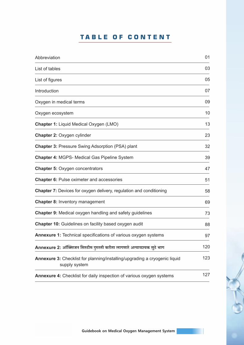
T A B L E O F C O N T E N T
Abbreviation
List of tables
List of figures
Introduction
Oxygen in medical terms
Oxygen ecosystem
Chapter 1: Liquid Medical Oxygen (LMO)
Chapter 2: Oxygen cylinder
Chapter 3: Pressure Swing Adsorption (PSA) plant
Chapter 4: MGPS- Medical Gas Pipeline System
Chapter 5: Oxygen concentrators
Chapter 6: Pulse oximeter and accessories
Chapter 7: Devices for oxygen delivery, regulation and conditioning
Chapter 8: Inventory management
Chapter 9: Medical oxygen handling and safety guidelines
Chapter 10: Guidelines on facility based oxygen audit
Annexure 1: Technical specifications of various oxygen systems
Annexure 2: Am°pŠgOZ {gñQ>r_ XþéñVr H$arVm bmJUmao AË`mdí`H$ gwQ>o ^mJ
Annexure 3: Checklist for planning/installing/upgrading a cryogenic liquid
supply system
Annexure 4: Checklist for daily inspection of various oxygen systems
01
03
05
07
09
10
13
23
32
39
47
51
58
69
73
88
97
120
123
127


1Guidebook on Medical Oxygen Management SystemGuidebook on Medical Oxygen Management System
T A B L E O F C O N T E N T
Annexure 5: Am°pŠgOZ g{_Vr gXñ` `m§Mo H$arVm _mJ©Xe©H$ gyMZm
Annexure 6: Daily oxygen calculations
Annexure 7: Safety training checklists
Annexure 8: CnbãY Am°pŠgOZMm `mo½` dmna H$aUo~m~V _mJ©Xe©H$ gyMZm
Annexure 9: Oxygen audit form
Annexure 10: Commonly needed tools for repair and maintenance of various
oxygen systems
References
130
132
133
137
146
156
159
ABBREVIATION
ARDS
ASME
ASU
BiPAP
BIS
CCC
CCE
CCOE
CFM
COPD
COVID-19
CPAP
ASTMA
Cu M
DCH
DCHC
DOT
ERP
HDU
HFNC
ICU
ISI
KL
LMO
LPM
MCB
MGPS
M&E
Acute Respiratory Distress Syndrome
American Society of Mechanical Engineers
Air Separation Units
Bilevel Positive Airway Pressure
Bureau of Indian Standards
Covid-19 Care Centre
Commission of the European Communities
Chief Controller of Explosive
Cubic Feet per Minute
Chronic Obstructive Pulmonary Disease
Corona Virus Disease-19
Continuous Positive Airway Pressure Therapy
American Society for Testing and Materials
Cubic Metre
Dedicated Covid-19 Hospital
Dedicated Covid Health Centre
Department of Transportation
Emergency Response Plan
High Dependency Units
High Flow Nasal Cannula
Intensive Care Unit
Indian Standards Institution
Kilolitre
Liquid Medical Oxygen
Litre Per Minute
Miniature Circuit Breaker
Medical Gas Pipeline System
Monitoring and Evaluation
MOHFW Ministry of Health and Family Welfare

3Guidebook on Medical Oxygen Management System2 Guidebook on Medical Oxygen Management System
ABBREVIATION
MT Metric Ton
NFPA National Fire Protection Association
NICU Neonatal Intensive Care Unit
NIV FiO2 Non-invasive Ventilation Fraction of Inspired Oxygen
O2 Oxygen
NRBM Non-Rebreather Mask
OC Oxygen Concentrator
OLED Organic Light-Emitting Diode
OT Operation Theatre
P&ID Piping and Instrumentation Diagram
PCC Plain Cement Concrete
PESO Petroleum And Explosives Safety Organization
PICU Paediatric Intensive Care Unit
PPE Personal Protective Equipment
PRV Pressure Relief Valve
PSA Pressure Swing Adsorption
SARS-CoV-2 Severe Acute Respiratory Syndrome Coronavirus-2
SMPV Static and Mobile Pressure Vessels
SOPs Standard Operating Procedure
SPO2 Saturation of Peripheral Oxygen
TUV Technischer Überwachungsverein, English translation: Technical Inspection Association
UNICEF United Nations Children's Emergency Fund
UPS Uninterruptible Power Supply
Union Territories
VIE Vacuum Insulated Evaporator
WHO World Health Organization
MOMC Medical Oxygen Monitoring Committee
UTs
LIST OF TABLES
Table 1: Oxygen system and the primary methods
Table 2: General characteristics of liquid oxygen tank
Table 3: Inspection and maintenance schedule of LMO
Table 4: Fault diagnosis/ troubleshooting of LMO
Table 5: Measurement of various sources in terms of jumbo cylinder
TABLE
Table 6: User care and preventive maintenance cylinders (and associated accessories) recommendations for oxygen
Table 7: Troubleshooting for oxygen cylinders (and associated accessories)
Table 8: Troubleshooting other issues of PSA
Table 9: Various options for gas supply
Table 10: Pipeline testing
Table 11: Preventive maintenance oxygen concentrators
Table 12: Troubleshooting and corrective maintenance of oxygen concentrator
Table 14: Common problems and remedies of pulse oximeter
Table 15: Description and comparison of flowmeters
Table 16: Description and comparison of flow splitting devices
Table 17: Description and comparison of humidifiers
Table 18: Description and comparison of oxygen delivery options
Table 19: Description and comparison of oxygen analysers
Table 20: Oxygen requirement/consumption based on bed strength
Table 21: Daily oxygen requirement/consumption based on active cases
Table 22: Oxygen availability at state, district/hospital level
Table 25: Oxygen management system issues, causes and solutions
Table 23: Do's and Don'ts - medical gas manifold room
Table 24: Do's and Don'ts - liquid oxygen
11
19
21
22
24
31
31
37
41
45
49
50
Table 13: Types pulse oximeter 51
55
58
61
62
63
65
71
71
72
81
85
92


5Guidebook on Medical Oxygen Management System4 Guidebook on Medical Oxygen Management System
Annexure Table 6: g|Q´>b Am°pŠgOZ {gpñQ>_ XþéñVr H$[aVm bmJUmao AË`mdí`H$ gwQ>o ^mJ
Annexure Table 7:
Annexure Table 8: Post operationalization PSA plant monitoring format
Annexure Table 10: Checklist for planning/installing/ upgrading a cryogenic liquid supply system
Annexure Table 11: Daily oxygen calculation sheet based on oxygen storage sources
Annexure Table 12: Daily oxygen calculation sheet based on output sources
TABLE
{b{¹$S> Q>±H$ {gñQ>r_ XþéñVrH$[aVm bmJUmao gwQ>o ^mJ
Annexure Table 2: Technical specifications for procurement- oxygen cylinders
Annexure Table 3: Technical specifications for medical gas pipeline system
Annexure Table 4: Capacity of the components of various plants
Annexure Table 5: Technical specifications for oxygen concentrators
LIST OF TABLES
Annexure Table 1: Technical specifications of Liquid Medical Oxygen 97
100
105
115
117
120
120
121
122
123
132
132
Annexure Table 9: Preventive maintenance checklists of PSA plant
Figure 1: Oxygen Systems
Figure 2: Oxygen sources
Figure 3: Cryogenic oxygen distillation process
Figure 4: Typical vacuum jacketed dewar
Figure 5 a: Cryogenic liquid cylinders
Figure 5 b: Typical cryogenic liquid cylinders top view
Figure 6: A typical station with a cryogenic storage tank
Figure 7: Working and construction of LMO tank & dura cylinder
Figure 8: Oxygen Cylinder type
Figure 9: Differences in color coding of different gases between ISO colour coding standard and United States convention
Figure 10: Oxygen Cylinder labelling
Figure 11: Oxygen Cylinder with accessories
Figure 12: Oxygen Cylinder size
Figure 13: Pressure swing adsorption plant
Figure 14: Medical gas piping system configuration
Figure 15: Area valve service unit
Figure 16: Area alarm panel
Figure 17: Diamond-type oxygen outlet point
Figure 18: Chemetron-type oxygen outlet point
Figure 19: A set of medical gases outlets/inlets
Figure 20: Pipeline identification colours
TABLE
LIST OF FIGURES
10
10
13
14
15
15
16
17
23
25
25
26
27
32
42
43
43
44
44
44
45
46Figure 21: Oxygen Manifold System

7Guidebook on Medical Oxygen Management System6 Guidebook on Medical Oxygen Management System
TABLE
Figure 22: Oxygen concentrator
Figure 24: Coiled Probe Cable
Figure 23: Types of probes
Figure 24: Description and comparison of flowmeters
Figure 25: Types of Thorpe Tube
Figure 26: Venturi mask
Figure 27: Types of ventilators
Figure 28: CPAP & BiPAP
Figure 29: The fire triangle
Figure 31: Oxygen safety signs
Figure 32: Labeling and signs for medical gas systems
LIST OF FIGURES
47
53
54
60
64
67
67
73
87
87
160Annexure Figure 1: Commonly needed tools for repair and
maintenance of various oxygen systems
Figure 30: Different sources of supply and key system components
including alarms.
82
Coronavirus Disease 2019 (COVID-19) is an acute respiratory disease caused by a novel
coronavirus (SARS-CoV-2). India is currently observing the second wave of the COVID-
19 infection. Patients with COVID-19 infection may present mild, moderate, or severe
illness; the latter includes severe pneumonia, Acute Respiratory Distress Syndrome
(ARDS), sepsis, and septic shock. Although the proportion of moderate to severe cases
among all Covid-19 cases have been relatively low, it has put huge strain on the country's
health systems.
Pneumonia, ARDS and septic shock have been the major complications in people with
COVID-19, who required hospitalization. Many patients with these respiratory
complications slip into hypoxemia, a condition when the oxygen level in the blood is
abnormally low. Oxygen is a lifesaving resource for the management of hypoxemia,
irrespective of its cause. It is included in the WHO's Essential Medicine List as an essential
medicine. Its use in emergency care, for anesthesia, in surgery and for managing acute
and chronic respiratory conditions is crucial and well documented. Oxygen of 93% +/-3%
purity is used for the care of medical conditions across a wide range of patients,
irrespective of their age or gender. It is produced for medical use in various forms by using
many different methods.
Monitoring the levels of oxygen saturation is recommended for all the patients with
symptomatic COVID-19 disease along with oxygen therapy for all severe and critical
COVID-19 patients with low oxygen saturation. Oxygen can be produced primarily in two
forms – the liquid form and the gaseous form, using various methods and devices.
Depending on a patient's need, it can also be administered at different flow rates through
various delivery options.
During the second wave of COVID-19 infection, a huge load of patients needed oxygen
therapy. The existing production and supply chain system were inadequate to meet patient
needs in various pockets across the country and the state. The Government of
Maharashtra implemented various strategies to fulfil the patient care needs for medicines
and oxygen. As a commitment to its people and considering long term systemic
improvement, the Government of Maharashtra is making all efforts to improve the
production and supply of medical oxygen, a lifesaving medicine, across the state.
This guidebook presents a comprehensive view at the entire oxygen ecosystem including
the production, storage, supply and distribution of medical oxygen and will be helpful to the
various stakeholders in this field.
INTRODUCT ION

9Guidebook on Medical Oxygen Management System8 Guidebook on Medical Oxygen Management System
OBJECTIVE OF THE HANDBOOK
The objective of the handbook is to provide guidance for making informed decision on
proper usage of oxygen devices according to the requirements and the resources
available in the health facilities in Maharashtra.
This document is intended for the administrators, state and district level officers,
procurement personnel, planning officers, program managers, biomedical engineers, and
medical and paramedical staff handling oxygen devices during its storage, transportation
and distribution.
Additionally, the handbook also provides tools for proper functioning, maintenance and
safety of the oxygen equipment and for conducting oxygen audit.
The information made available in this guidebook has been sourced from different
resources / documents available with WHO, PESO, Ministry of Health and Family Welfare,
among others.
We hope that this handbook will be helpful to all the stakeholder involved in oxygen
ecosystem in the state of Maharashtra in addressing the gaps identified in the continuous
and adequate supply of medical oxygen.
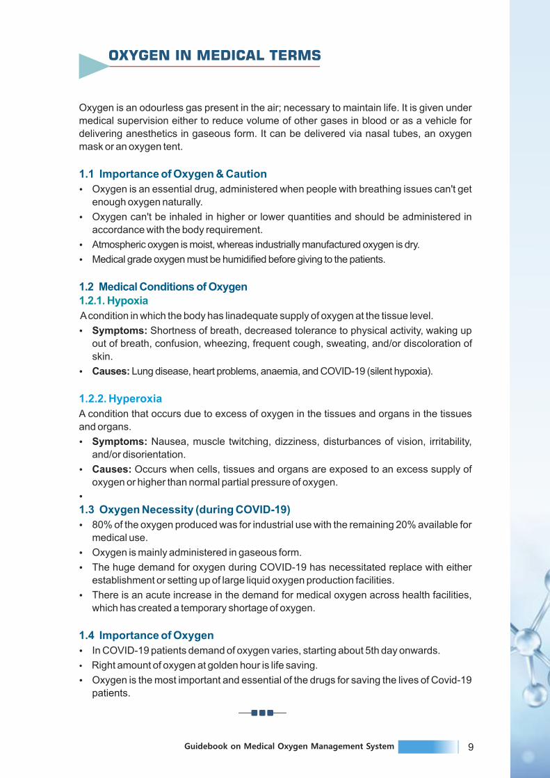
Oxygen is an odourless gas present in the air; necessary to maintain life. It is given under
medical supervision either to reduce volume of other gases in blood or as a vehicle for
delivering anesthetics in gaseous form. It can be delivered via nasal tubes, an oxygen
mask or an oxygen tent.
1.1 Importance of Oxygen & Caution
Ÿ Oxygen is an essential drug, administered when people with breathing issues can't get
enough oxygen naturally.
Ÿ Oxygen can't be inhaled in higher or lower quantities and should be administered in
accordance with the body requirement.
Ÿ Atmospheric oxygen is moist, whereas industrially manufactured oxygen is dry.
Ÿ Medical grade oxygen must be humidified before giving to the patients.
1.2 Medical Conditions of Oxygen1.2.1. Hypoxia
A condition in which the body has linadequate supply of oxygen at the tissue level.
Ÿ Symptoms: Shortness of breath, decreased tolerance to physical activity, waking up
out of breath, confusion, wheezing, frequent cough, sweating, and/or discoloration of
skin.
Ÿ Causes: Lung disease, heart problems, anaemia, and COVID-19 (silent hypoxia).
1.2.2. Hyperoxia
A condition that occurs due to excess of oxygen in the tissues and organs in the tissues
and organs.
Ÿ Symptoms: Nausea, muscle twitching, dizziness, disturbances of vision, irritability,
and/or disorientation.
Ÿ Causes: Occurs when cells, tissues and organs are exposed to an excess supply of
oxygen or higher than normal partial pressure of oxygen.
Ÿ
1.3 Oxygen Necessity (during COVID-19)
Ÿ 80% of the oxygen produced was for industrial use with the remaining 20% available for
medical use.
Ÿ Oxygen is mainly administered in gaseous form.
Ÿ The huge demand for oxygen during COVID-19 has necessitated replace with either
establishment or setting up of large liquid oxygen production facilities.
Ÿ There is an acute increase in the demand for medical oxygen across health facilities,
which has created a temporary shortage of oxygen.
1.4 Importance of Oxygen
Ÿ In COVID-19 patients demand of oxygen varies, starting about 5th day onwards.
Ÿ Right amount of oxygen at golden hour is life saving.
Ÿ Oxygen is the most important and essential of the drugs for saving the lives of Covid-19
patients.
OXYGEN IN MEDICAL TERMS
9Guidebook on Medical Oxygen Management System8 Guidebook on Medical Oxygen Management System
OBJECTIVE OF THE HANDBOOK
The objective of the handbook is to provide guidance for making informed decision on
proper usage of oxygen devices according to the requirements and the resources
available in the health facilities in Maharashtra.
This document is intended for the administrators, state and district level officers,
procurement personnel, planning officers, program managers, biomedical engineers, and
medical and paramedical staff handling oxygen devices during its storage, transportation
and distribution.
Additionally, the handbook also provides tools for proper functioning, maintenance and
safety of the oxygen equipment and for conducting oxygen audit.
The information made available in this guidebook has been sourced from different
resources / documents available with WHO, PESO, Ministry of Health and Family Welfare,
among others.
We hope that this handbook will be helpful to all the stakeholder involved in oxygen
ecosystem in the state of Maharashtra in addressing the gaps identified in the continuous
and adequate supply of medical oxygen.
Oxygen is an odourless gas present in the air; necessary to maintain life. It is given under
medical supervision either to reduce volume of other gases in blood or as a vehicle for
delivering anesthetics in gaseous form. It can be delivered via nasal tubes, an oxygen
mask or an oxygen tent.
1.1 Importance of Oxygen & Caution
Ÿ Oxygen is an essential drug, administered when people with breathing issues can't get
enough oxygen naturally.
Ÿ Oxygen can't be inhaled in higher or lower quantities and should be administered in
accordance with the body requirement.
Ÿ Atmospheric oxygen is moist, whereas industrially manufactured oxygen is dry.
Ÿ Medical grade oxygen must be humidified before giving to the patients.
1.2 Medical Conditions of Oxygen1.2.1. Hypoxia
A condition in which the body has linadequate supply of oxygen at the tissue level.
Ÿ Symptoms: Shortness of breath, decreased tolerance to physical activity, waking up
out of breath, confusion, wheezing, frequent cough, sweating, and/or discoloration of
skin.
Ÿ Causes: Lung disease, heart problems, anaemia, and COVID-19 (silent hypoxia).
1.2.2. Hyperoxia
A condition that occurs due to excess of oxygen in the tissues and organs in the tissues
and organs.
Ÿ Symptoms: Nausea, muscle twitching, dizziness, disturbances of vision, irritability,
and/or disorientation.
Ÿ Causes: Occurs when cells, tissues and organs are exposed to an excess supply of
oxygen or higher than normal partial pressure of oxygen.
Ÿ
1.3 Oxygen Necessity (during COVID-19)
Ÿ 80% of the oxygen produced was for industrial use with the remaining 20% available for
medical use.
Ÿ Oxygen is mainly administered in gaseous form.
Ÿ The huge demand for oxygen during COVID-19 has necessitated replace with either
establishment or setting up of large liquid oxygen production facilities.
Ÿ There is an acute increase in the demand for medical oxygen across health facilities,
which has created a temporary shortage of oxygen.
1.4 Importance of Oxygen
Ÿ In COVID-19 patients demand of oxygen varies, starting about 5th day onwards.
Ÿ Right amount of oxygen at golden hour is life saving.
Ÿ Oxygen is the most important and essential of the drugs for saving the lives of Covid-19
patients.
OXYGEN IN MEDICAL TERMS

11Guidebook on Medical Oxygen Management System10 Guidebook on Medical Oxygen Management System
Oxygen ecosystem involves devices, instruments and equipment used from the
production of oxygen to supplying it to the patient as well as for monitoring the oxygen
levels. The oxygen ecosystem includes sources of oxygen production, its distribution,
regulation, delivery and patient monitoring. The oxygen ecosystem with its components
and sub-components, is shown in Figure 1 below.
Oxygen Source DistributionDelivery
PatientMonitoring
Regulation andConditioning
Concentrator
Cylinder
PSA/VSA/VPSA
Plant
Liquid Medical
Oxygen
(ASU Plant)
Central or
sub-central
piping
Tubing
Transport
(for cylinders)
Transport
(for Liquid
Oxygen)
Regulator
Flowmeter
Flowmeter stand
(flow splitter)
Humidifier
(heated and
non-heated)
Blender
CPAP
BiPAP
Ventilator
Nasal cannula
Nasal catheter
Masks
Tubing
Non ReBreather
Mask
Pulse oximeter
Multiparameter
monitor
Power Supply
Figure 1: Oxygen System
Maintenance
Oxygen analyzers Tools and spare parts for maintenance of all devices
Oxyge n Ec osys t e m
Major sources of oxygen supply: Oxygen to medical facilities is supplied through four primary
methods:
Oxyge n sourc e s
Oxygen supply options
Store and supply
Generate and Supply
Oxygen Cylinders
Liquid Oxygen
Oxygen Concentrators
Oxygen Generators
Figure 2: Oxygen Sources
Backup power supply Surge suppressorsVoltage stabilizers
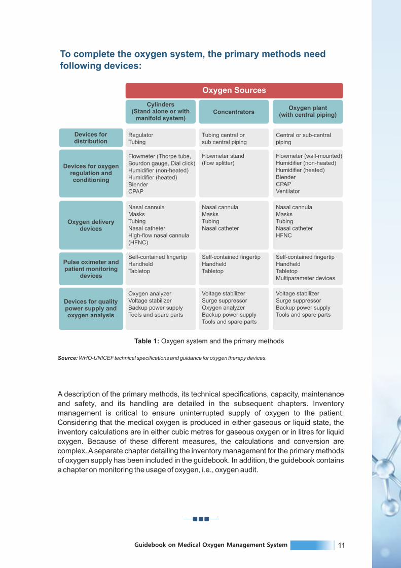
To complete the oxygen system, the primary methods needfollowing devices:
A description of the primary methods, its technical specifications, capacity, maintenance
and safety, and its handling are detailed in the subsequent chapters. Inventory
management is critical to ensure uninterrupted supply of oxygen to the patient.
Considering that the medical oxygen is produced in either gaseous or liquid state, the
inventory calculations are in either cubic metres for gaseous oxygen or in litres for liquid
oxygen. Because of these different measures, the calculations and conversion are
complex. A separate chapter detailing the inventory management for the primary methods
of oxygen supply has been included in the guidebook. In addition, the guidebook contains
a chapter on monitoring the usage of oxygen, i.e., oxygen audit.
Cylinders(Stand alone or with
manifold system)Concentrators
Oxygen plant(with central piping)
RegulatorTubing
Tubing central orsub central piping
Central or sub-centralpiping
Flowmeter (Thorpe tube,Bourdon gauge, Dial click)Humidifier (non-heated)Humidifier (heated)BlenderCPAP
Flowmeter stand(flow splitter)
Flowmeter (wall-mounted)Humidifier (non-heated)Humidifier (heated)BlenderCPAPVentilator
Nasal cannulaMasksTubingNasal catheterHigh-flow nasal cannula(HFNC)
Nasal cannulaMasksTubingNasal catheter
Nasal cannulaMasksTubingNasal catheterHFNC
Self-contained fingertipHandheldTabletop
Self-contained fingertipHandheldTabletop
Self-contained fingertipHandheldTabletopMultiparameter devices
Devices fordistribution
Devices for oxygenregulation andconditioning
Oxygen deliverydevices
Pulse oximeter andpatient monitoring
devices
Devices for qualitypower supply andoxygen analysis
Oxygen analyzerVoltage stabilizerBackup power supplyTools and spare parts
Voltage stabilizerSurge suppressorOxygen analyzerBackup power supplyTools and spare parts
Voltage stabilizerSurge suppressorBackup power supplyTools and spare parts
Oxygen Sources
Source: WHO-UNICEF technical specifications and guidance for oxygen therapy devices.
Table 1: Oxygen system and the primary methods
OXYGEN ECOSYSTEM
11Guidebook on Medical Oxygen Management System10 Guidebook on Medical Oxygen Management System
Oxygen ecosystem involves devices, instruments and equipment used from the
production of oxygen to supplying it to the patient as well as for monitoring the oxygen
levels. The oxygen ecosystem includes sources of oxygen production, its distribution,
regulation, delivery and patient monitoring. The oxygen ecosystem with its components
and sub-components, is shown in Figure 1 below.
Oxygen Source DistributionDelivery
PatientMonitoring
Regulation andConditioning
Concentrator
Cylinder
PSA/VSA/VPSA
Plant
Liquid Medical
Oxygen
(ASU Plant)
Central or
sub-central
piping
Tubing
Transport
(for cylinders)
Transport
(for Liquid
Oxygen)
Regulator
Flowmeter
Flowmeter stand
(flow splitter)
Humidifier
(heated and
non-heated)
Blender
CPAP
BiPAP
Ventilator
Nasal cannula
Nasal catheter
Masks
Tubing
Non ReBreather
Mask
Pulse oximeter
Multiparameter
monitor
Power Supply
Figure 1: Oxygen System
Maintenance
Oxygen analyzers Tools and spare parts for maintenance of all devices
Oxyge n Ec osys t e m
Major sources of oxygen supply: Oxygen to medical facilities is supplied through four primary
methods:
Oxyge n sourc e s
Oxygen supply options
Store and supply
Generate and Supply
Oxygen Cylinders
Liquid Oxygen
Oxygen Concentrators
Oxygen Generators
Figure 2: Oxygen Sources
Backup power supply Surge suppressorsVoltage stabilizers
To complete the oxygen system, the primary methods needfollowing devices:
A description of the primary methods, its technical specifications, capacity, maintenance
and safety, and its handling are detailed in the subsequent chapters. Inventory
management is critical to ensure uninterrupted supply of oxygen to the patient.
Considering that the medical oxygen is produced in either gaseous or liquid state, the
inventory calculations are in either cubic metres for gaseous oxygen or in litres for liquid
oxygen. Because of these different measures, the calculations and conversion are
complex. A separate chapter detailing the inventory management for the primary methods
of oxygen supply has been included in the guidebook. In addition, the guidebook contains
a chapter on monitoring the usage of oxygen, i.e., oxygen audit.
Cylinders(Stand alone or with
manifold system)Concentrators
Oxygen plant(with central piping)
RegulatorTubing
Tubing central orsub central piping
Central or sub-centralpiping
Flowmeter (Thorpe tube,Bourdon gauge, Dial click)Humidifier (non-heated)Humidifier (heated)BlenderCPAP
Flowmeter stand(flow splitter)
Flowmeter (wall-mounted)Humidifier (non-heated)Humidifier (heated)BlenderCPAPVentilator
Nasal cannulaMasksTubingNasal catheterHigh-flow nasal cannula(HFNC)
Nasal cannulaMasksTubingNasal catheter
Nasal cannulaMasksTubingNasal catheterHFNC
Self-contained fingertipHandheldTabletop
Self-contained fingertipHandheldTabletop
Self-contained fingertipHandheldTabletopMultiparameter devices
Devices fordistribution
Devices for oxygenregulation andconditioning
Oxygen deliverydevices
Pulse oximeter andpatient monitoring
devices
Devices for qualitypower supply andoxygen analysis
Oxygen analyzerVoltage stabilizerBackup power supplyTools and spare parts
Voltage stabilizerSurge suppressorOxygen analyzerBackup power supplyTools and spare parts
Voltage stabilizerSurge suppressorBackup power supplyTools and spare parts
Oxygen Sources
Source: WHO-UNICEF technical specifications and guidance for oxygen therapy devices.
Table 1: Oxygen system and the primary methods
OXYGEN ECOSYSTEM

13Guidebook on Medical Oxygen Management System12 Guidebook on Medical Oxygen Management System
1. BRIEF INTRODUCTION
Liquid oxygen is a cryogenic liquid. It is pale blue in colour and is extremely cold.
Cryogenic liquids are liquefied gases that have a normal boiling point below –130°F
(–90°C). Liquid oxygen has a boiling point of –297°F (–183°C). It is a compressed form of
oxygen, required to be stored much below -200°C, to ensure that the oxygen remains in
the liquid form.
Because the temperature difference between the product and the surrounding
environment is substantial—even in the winter—keeping the liquid oxygen insulated from
the surrounding heat is essential. The product also requires special equipment for
handling and storage.
LIQUID MEDICAL OXYGEN
The above figure explains the cryogenic oxygen distillation process. Cryogenic distillation
separates oxygen from air by liquefying air at very low temperatures (-300°F). Ambient air
is compressed in multiple stages with inter-stage cooling then further cooled with chilled
water. Residual water vapor, carbon dioxide, and atmospheric contaminants are removed
in molecular sieve adsorbers.
Oxygen is often stored as a liquid, although used primarily as a gas. Liquid storage is less
bulky and less costly than the equivalent capacity of high-pressure gaseous storage. A
typical storage system consists of a cryogenic storage tank, one or more vaporizers and a
pressure control system. The cryogenic tank is constructed, in principle, like a vacuum
bottle. There is an inner vessel surrounded by an outer vessel. Between the vessels is an
annular space that contains an insulating medium from which all the air has been
removed. This space keeps heat away from the liquid oxygen held in the inner vessel.
Vaporizers convert the liquid oxygen into a gaseous state. A pressure control manifold
then controls the gas pressure that is fed to the process or application.
Vessels used in liquid oxygen service should be designed for the pressure and
temperatures involved. Piping design should follow similar design and conform to national
standards and codes.
C H A P T E R 1
Figure 3: Cryogenic Oxygen Distillation Process
Cryogenic Oxygen Distillation Process
CryogenicDistillation
is the process in which Nitrogen/
Argon andOxygen areseparatedfrom air.
‘Cryogenic’ isrelated to low
temperatures and ‘Distillation’ is related to
separation of constituents from a mixture by utilizing
the property of boiling point of the
constituents.
Thus in cryogenic
distillations, the components having
very low boiling points are distilled selectively at low
temperatures.
This methodproduces products of high purity but it is also very quite energy intensive.

15Guidebook on Medical Oxygen Management System14 Guidebook on Medical Oxygen Management System
1.1 Liquid Oxygen Containers
Liquid oxygen is stored, shipped, and handled in several types of containers, depending
upon the quantity required by the user. The types of containers in use include the dewar,
cryogenic liquid cylinder, and cryogenic storage tank. Storage quantities vary from a few
liters to many thousands of gallons. (In India IS 7396:2017 is followed.)
Since heat leak is always present, vaporization takes place continuously. Rates of
vaporization vary, depending on the design of the container, external temperatures and
the volume of stored product. Containers are designed and manufactured according to the
applicable codes and specifications for the temperatures and pressures involved.
1.1.1. Dewars
This type of container is non-pressurized. A loose-fitting dust cap over the outlet of the
neck tubes prevents atmospheric moisture from plugging the neck and allows gas
produced from vaporized liquid to escape. The most common unit of measure for the
capacity of a dewar is the liter. Five- to 200-liter dewars are available. Product may be
removed from small dewars by pouring, while larger sizes will require a transfer tube.
Cryogenic liquid cylinders that are pressurized vessels are sometimes incorrectly referred
to as dewars. These typical Dewars has no application in Liquid Medical Oxygen use.
Figure 4: Typical vacuum
jacketed Dewar
Figure 5a: Cryogenic liquid cylinders
Figure 5b: Typical cryogenic liquid cylinder, top view
1.1.2 Cryogenic liquid cylinders (Dura Cylinder)
A typical cryogenic liquid cylinder is depicted in following figures. This is an insulated,
vacuum-jacketed pressure vessel. They are equipped with pressure relief valves and
rupture disks to protect the cylinders from pressure buildup. Liquid containers operate at
pressures in the range of 100 psig to 350 psig (24 atm) and have capacities between 80
and 450 liters of liquid. Oxygen may be withdrawn as a gas by passing liquid through an
internal vaporizer or as a liquid under its own vapor pressure. (In India typically Dura
Cylinders of capacity of 180 L to 250 L are deployed. They come with warranty ranging
from 1-3 years.)

17Guidebook on Medical Oxygen Management System16 Guidebook on Medical Oxygen Management System
1.1.3 Cryogenic storage tanks
Customer installations generally include a tank, vaporizer, and pressure control manifold
(see below figure). Tanks are generally cylindrical in shape and are mounted in fixed
locations as stationary vessels or on railcar or truck chassis for easy transportation. All
tanks are powder- and vacuum-insulated in the annular space and equipped with various
circuits to control product fill, pressure buildup, pressure-relief, product withdrawal, and
tank vacuum. Tanks are designed to national and international specifications for the
pressures and temperatures involved.
Figure 6: A typical station with a cryogenic storage tank
Typical Vaporizer
Typical Oxygen Cryogenic
Bulk Tank
1.2 Working and construction of LMO tank
The LMO tank working and construction is as per the diagram below -
LMO Plant /Dura Cylinder
Outlet - Vapourizer Vapourizer exchanges
heat from the atmospheric air
Have fins (like ACs and
Radiators) but in a very
different and large proportions
When oxygen passed throughvapourizer, it will exchange heat from the atmosphere & liquid oxygen will
get converted into gaseous form
Water will solidify and have ice
accumulations on the pipeline
outside, where it is still very cold
Now, oxygen is converted
into gaseous form, & when this
happens, it is boiling and expanding
To cut this boiling and expanding, pressure
regulatory valves required to step down the
pressure gradually into the pipelines
At this point, oxygen can be
delivered to the oxygen
points / ventilators
Figure 7: Working and construction of LMO tank & dura cylinder

19Guidebook on Medical Oxygen Management System18 Guidebook on Medical Oxygen Management System
2. PREREQUISITE FOR LIQUID OXYGEN TANK INSTALLATION
2.1 Following points should be taken into consideration by the Hospital/facility while installing LMO
Ÿ Open land space (uncovered).
Ÿ Civil Work and PESO approval.
Ÿ PESO approval for filling, storage and operation of the Medical Oxygen Installation.
Ÿ Crane/Hydra arrangement for unloading Tank and Vaporiser from truck/trailer and
Installation on the foundation.
Ÿ Fencing and gate around the Installation.
Ÿ Fire extinguisher and water connection, Lighting, Safety Signages and Earthing pit.
2.2 PESO Regulations to be followed for the Installation
Ÿ Allocated space for Installation Space: W x L: (9 m x 15 m typical).
Ÿ At ground level, without overhead power or other utility cable.
Ÿ Assigned space to be well connected with internal roads for smooth movement of LMO
transport tanker from/to the Installation.
Source –
1. PESO - https://peso.gov.in/web/smpv-u-rules-2016
2. Website of INOXINDIA -https://www.inoxindia.com/inoxindia/covid19.php
Liquid medical oxygen installation and other modes of supply have their respective
logistics, Installation and set-up arrangements. Therefore, extent of benefits and
advantages of Liquid medical oxygen system varies depending on Hospital size (bed
capacity), location, consumption, local supply and service support. The design and
installation of medical oxygen supply system for healthcare facilities follows specific
requirement and guidelines outlined in following international standards globally;
Ÿ HTM 02-01 Medical gas pipeline system – Part A, Design, installation, validation and
verification.
Ÿ AIGA 049/17 Guideline to Medical oxygen supply system for Healthcare facilities.
Ÿ NFPA 55 – 2016 – Chapter 9, Bulk Oxygen Systems.
General Characteristics Liquid Oxygen
DescriptionBulk liquid oxygen generated off-site and stored in a large tank and supplied throughout a health facility via a central pipeline system.Tank requires refilling by liquid oxygen supplier.
Clinical applicationand/or use case
Can be used for all oxygen needs, including high-pressure supply andin facilities where power supply is intermittent or unreliable.
Appropriate levelof health system Secondary and tertiary.
Distribution mechanism Central pipeline distribution system.
Electricity requirement No.
Initial costs Can be high; tank, pipeline installation and civil.
Ongoing operating costs Moderate (can be high if tank is leased); refill costs, maintenance.
Maintenance requirementPeriodical maintenance of system and piping required by highly trainedtechnicians and engineers, can be provided as part of contract.
User care Minimal; at terminal unit only.
Requires transport/ supply chain.
Exhaustible supply.
High maintenance for piping.
High total cost.
Needs adequate infrastructure.
Requires backup cylinder supply.
Risk of gas leakage from piping system.
Drawbacks
99% purity of oxygen obtained.High oxygen output for small space requirement. Merits
Table 2: General characteristics of liquid oxygen tank

21Guidebook on Medical Oxygen Management System20 Guidebook on Medical Oxygen Management System
2.3 Pros and cons of LMO
a) Pros
Liquid oxygen can be stored in a portable tank and connected to a Central pipeline. Liquid
oxygen is highly concentrated, so more oxygen can be stored in a smaller tank and ensure
continuous supply at high pressure. Most cost-effective system for larger facilities.
b) Cons
Liquid oxygen cannot be stored for more than a week or two because it will vaporize
(evaporate) and build-up pressure inside storage tank. The tank's content must be
consumed and refilled often, requiring the scheduling of deliveries. In addition, the system
need PESO license compliance.
3. MAINTENANCE
All routine preventive maintenance and break-down maintenance of the liquid oxygen
storage system should be done by the vendor or authorised trained personnel only.
Experienced trained personnel should be readily available.
Log of all works undertaken in the system should be meticulously maintained by the
vendor.
3.1 Routine inspection, checks and maintenance
Cleaning
Ÿ The use of abrasive or solvent based cleaning solutions is not recommended.
Ÿ Cleaning external surfaces - use a damp cloth only. Mild soap solution may be used but
detergent/ surfactant solutions are not recommended.
Ÿ Phenol or halogen-based disinfectants or agents that release chlorine or oxygen
should not be used.
Minimum requirements
Ÿ Minimum requirements for routine inspections, checks and maintenance are given in
Table and must be observed to ensure continued safe operation of the system.
3.2 Fault diagnosis/ troubleshooting
There are several faults that can be diagnosed. These are relatively simple to resolve,
without replacing expensive regulator assemblies. Most faults can be avoided by
undertaking a regular planned preventive maintenance routine, carried out by a
competent person.
Actions Commissioning Monthly Quarterly Annually 5 Yearly
Ambient temperature
Suitability of location
Adequate roomfor ventilation
Adequate accessfor maintenance
Visually inspect theunit for damage
Planned preventive maintenance
Complete commissioningprocedure
Inspection, checks and tests
ü ü
ü
ü
ü
ü
ü ü ü
ü
ü ü üTable 3: Inspection and maintenance Schedule of LMO

23Guidebook on Medical Oxygen Management System22 Guidebook on Medical Oxygen Management System
Remarks/rectification action
Failure to reach or maintain operating
pressure
Increase capacity ofpressure building
Refill tank
Seal
Replace
Clean
Correct adjustment or replace regulator-see Maintenance section
Erroneous or irregular contents gauge readings
Close or replace
Readjust
Seal
Replace, or return tomanufacturer for repair
Main safety valve leaking
Repair / Replace
Inner vessel burstingdisk has burst
Replace
Shut-off valves leaking
Replace
Tighten
Replace seat
Loss of vacuum
Replace
Seal
Wrong or incorrectvacuum gauge reading
Calibrate
Replace
Replace
Possible Cause
Excessive withdrawal
Liquid level too low
Leaks on outer piping
Safety valves do not close
Strainer at inlet of pressurebuilding regulator clogged
Improper adjustment ofregulator, or regulatordefective
Bypass valve not closed orleaking
Wrong adjustment
Leaking in differential pressure pipes or connections
Gauge damaged or leaking
Dirt or ice under disk cone
Bursting disk with too low pressure
Corrosion or material fatigue
Valve seat loose
Damaged seat or cone
Leak on vacuum bursting disk
Leaking measuring socket
Gauge not properly calibrated
Batteries have no charge
Defective vacuum gauge tube
Table 4: Fault diagnosis/ troubleshooting of LMO
1. BRIEF INTRODUCTION
Oxygen gas can be compressed and stored in cylinders (Figure 8). These cylinders are
filled at a gas manufacturing plant, either via a cryogenic distillation/ASUs in liquid oxygen
form or a process known as pressure swing adsorption (PSA) in gaseous oxygen form or
by an LMO-based re-filler and transported to health facilities to be connected to manifold
systems (groups of cylinders linked in parallel) that are piped to areas of the health facility;
or cylinders can be used directly within patient areas. The use of cylinders typically
involves transport to and from the bulk supply depot for regular refilling, which could have
logistical challenges and ongoing cost implications, often leading to unreliable supply in
many settings. Though it is not so common, cylinders in gaseous form can also be filled by
a PSA oxygen plant that is co-located with a health facility and that has a high-pressure
compressor for cylinder filling purposes.
Cylinders do not require electricity, but they do require several accessories and fittings to
deliver oxygen, such as pressure gauges, regulators, flowmeters, and, in some cases,
humidifiers. Cylinders also require periodic maintenance, commonly provided by gas
suppliers at the point of refilling. In this chapter, we will see the colour codes of medical gas
cylinders, user care and preventative maintenance and troubleshooting
recommendations for oxygen cylinders.
Figure 8: Oxygen cylinder Types
Cylinders type
(Gaseous Medical Oxygen)
Dura Cylinder
(Liquid Medical Oxygen)
OXYGEN CYLINDERC H A P T E R 2

25Guidebook on Medical Oxygen Management System24 Guidebook on Medical Oxygen Management System
1.1 Cylinder naming and sizing
Oxygen cylinders are of different sizes.Cylinder sizes for medical gases are named
alphabetically, unlike industrial cylinders which are numbered. In India and Maharashtra
most commonly used cylinders are D type (Jumbo) and B type (Portable) cylinders which
contains gaseous. oxygen, Dura cylinders with liquid oxygen are also used in the region.
Cylinders are fitted with customized valves (either pin index or bullnose type) that are
opened with valve keys, and with valve guards for safety. The Pin Index Safety System
(PISS) is designed to ensure the correct gas is connected to the regulator or other
equipment. The arrangement of the pins is unique for each gas, and the positions of the
holes on the cylinder valve must correspond with the pins to prevent the use of the wrong
gas. Some cylinders have built-in, integral pressure regulators, which do not require a
separate pressure regulator to be fitted to the cylinder valve before use.
Type of Cylinder Capacity in litersCapacity in
3CuM (m )
Equivalent toJumbo cylinders
3in CuM (m )
Type B (Gaseous O2) 1.5 -
Dura Cylinder 180 L (Liquid) 180 158 ~23
Dura Cylinder 200 L (Liquid) 200 175 25
Dura Cylinder 225 L (Liquid) 250 219 31
Oxygen Tank 3KL 3000 2633 376
Oxygen Tank 6KL 6000 5267 752
Oxygen Tank 10KL 10000 8778 1254
Oxygen Tank 20KL 20000 17556 2508
Type D Jumbo (Gaseous O2) 7000 7 1
1500
Table 5: Measurement of various sources in terms of jumbo cylinderTable 5: Measurement of various sources in terms of jumbo cylinder
1.2 Colour coding for gases
The international standard for the colour coding of gas cylinders is ISO 32: 1977 Gas
cylinders for medical use – Marking for identification of content. According to the ISO
standard, oxygen should be labeled as white. The below figure shows differences in gas
cylinder colour coding between ISO and US standards.
Figure 9: Differences in colour coding of different gases between ISO colour
coding standard and United States convention
1.3 Cylinder labelling
Medical gas cylinders are required to be labelled, as the primary means of identifying the
contents of the cylinder. The colour of the cylinder is only a guide. Labels for gas cylinders
can be reduced in size and shape to the dimensions specified in ISO 7225 – Gas cylinders
– Precautionary labels. The below figure is an example of a typical label.
Figure 10: Oxygen cylinder labelling

27Guidebook on Medical Oxygen Management System26 Guidebook on Medical Oxygen Management System
A. Diamond hazard label: displaying the primary hazard with additional hazard labels
displaying any subsidiary hazards. These labels will display the dangerous goods
classification number.
B. UN number: preceded by the letters UN. The UN number is a number assigned by the
United Nations Committee of Experts on the Transport of Dangerous Goods. The UN
number for compressed oxygen is UN 1072.
C. Proper shipping name.
D. Product name (may be omitted if the proper shipping name is identical).
E. Signal word, hazard and precautionary statements.
F. EC number (if applicable).
G. Package size and pressure.
H. Company name.
I. Address of the gas company.
J. Additional company information.
K. Contact telephone number.
Note : See British Compressed Gases Association. Technical information sheet 6.
Revision 2: 2012. Cylinder identification. Colour coding and labelling requirements; 2012
1.4 Oxygen cylinder accessories
The following figure shows the accessories required for the cylinder's installation.
These are flowmeter, pressure gauge, humidifier, cylinder key, pressure regulator,
and trolley.
Figure 11: Oxygen cylinder with accessories
1.5 Oxygen cylinder description (Type B and D)
Cylinder – Gaseous Oxygen Storing Capacity
Type B Small Cylinder- 1500 liters
Type D Jumbo Cylinder- 7000 liters
Figure 12: Oxygen cylinder size
1.5.1. B-Type Small Medical Oxygen Cylinder (1.5 CU.M.)
Ÿ B-type high pressure seamless cylinder for medical oxygen gas, cylinder is ISI marked
conforming to IS:7285 part 2, certified by the Bureau of Indian Standards (BIS) and
approved by the chief controller of explosive (CCOE) Government of India.
Ÿ Cylinder made from manganese steel.
Ÿ 10.2 ltr. Water capacity (40 cu.ft.).
Ÿ Valve made of brass and chrome plated.2
Ÿ Working pressure 150 kg. F/cm at 15 deg. C.2
Ÿ Hydraulic test pressure 250 kg. F/cm .
Ÿ Colour code of the cylinder should be as per IS: 3933-1966 with updating till date.
Ÿ Filled with medical oxygen gas of medical grade.
Ÿ Matching key cum spanner to release oxygen for each cylinder separately.
Ÿ Minimum two years guarantee for cylinder.
1.5.2. D-Type Jumbo Medical Oxygen cylinder (7 CU.F.M.)
Ÿ Cylinder made from manganese steel.
Ÿ 46.7 Ltr. water capacity (220 CU.FT.).
Ÿ Valve made of brass and chrome plated.2
Ÿ Working pressure 150 Kg. f/cm at 15 deg. C.2
Ÿ Hydraulic test pressure 250 Kg. f/cm .
Ÿ Filled with medical oxygen gas of medical grade.
Ÿ Matching key cum spanner to release oxygen for each cylinder separately.
Ÿ Minimum two years guarantee for cylinder.
(Source: Specification of medical oxygen cylinder- Rajasthan Medical Services
Corporation Limited, Jaipur)

29Guidebook on Medical Oxygen Management System28 Guidebook on Medical Oxygen Management System
1.5.3. Working of Manifold
Ÿ Jumbo manifold system has two banks and one reserve bank.
Ÿ Each bank connected to a common header with a separate manifold pressure regulator
& and banks alternately supply the pipeline.
Ÿ Manifold system operates on differential pressure mechanism.
Ÿ The secondary bank comes into operation automatically when content of the primary
bank is exhausted.
Ÿ Manifold control panel assists in switching automatically between left bank and right
bank.
Ÿ Automatic control panel need no power or electricity requirement for operation.
Ÿ In case of power failure, control panel has fail-safe mechanism, if required.
Ÿ Both right and left bank opens in case of power failure and will ensure unobstructed flow
to hospital on self-displacement method.
1.5.4. Oxygen Cylinder – Pros and Cons
Pros
Ÿ Installation does not need permission from any authority like Petroleum and Explosives
Safety Organization (PESO).
Ÿ Space accommodating as construction is long and linear.
Ÿ Easy setup, can also be used bedside without medical gas pipe system.
Cons
Ÿ Recommended as primary source for small size hospital up to 30 beds.
Ÿ Not recommended (specially in current pandemic) as primary source to ICU's.
Ÿ Erratic supply chain.
Ÿ Chances of carrying infection.
1.6 Dura Oxygen Cylinder-
1.6.1. Introduction
Ÿ Dura cylinders are small portable LMO tanks that stores liquid oxygen.
Ÿ They have capacity to store approx 200 to 240 liters of liquid oxygen in each cylinder.
Ÿ Some have inbuilt vaporizer and safety valves to maintain the pressure of oxygen.
Ÿ Dura cylinders are sent to plants for refilling as they are small in size and portability.
Ÿ An external vaporizer is required if more than one dura cylinder is used. PRV is also
required if a dura cylinder bank is used.
Ÿ Dura cylinders should be purchased with a proper trolley as they are very heavy.
Ÿ There should be either a vehicle to pick and drop to refill the dura cylinders or dura
cylinders should have an in-built chain pulling system / alternative system to lift the dura
cylinder. The third option includes sub-system installed on the hospital premise.
1.6.2. Technical Specification for Dura Oxygen Cylinder
Dura liquid oxygen cylinder (capacity : 200 Litter) with following set up,
Ÿ Should include its dura trolley and facility to carry by crain notch.
Ÿ Should include its complete connection kit to panel of our facility.
Ÿ Service: Oxygen.
Ÿ Gross capacity: 208 Ltr.
Ÿ Net capacity: 198 Ltr.
Ÿ Relief valve setting : 17 to 24 bar.
Ÿ Dimension: diameter : 20 inch.
Ÿ Height : 65 inch.
Ÿ Empty weight : 136 kg.
Cryogenic Medical Oxygen gas system3
Ÿ Vaporizer 100 Nm /hr-1 No.
Ÿ Inlet manifold – 5 inlets
Ÿ Outlet manifold with appropriate connector 1"-01 Nos.3
Ÿ Outlet gas line regulator with low pressure high flow- 100 Nm - 1 No.
Ÿ 3/8'' hose pipe - 1 No. length 2 meter long.
Dura cylinder should certify with BIS/department of transportation (DOT)/TUV or similar,
ISO 9001 - 2005, PESO fire explosive and approved by the chief controller of explosive
(CCOE) Government of India. (should attach all certificates, double mate for accidental
safety).
1.6.3. Dura Cylinders – Installation Guidelines
Ÿ Dura is primary source of supply for smaller hospitals and could be secondary source of
supply for larger hospitals.
Ÿ Recommended as primary source for hospital up to 100 beds with ICU of maximum 10
beds.
Ÿ Dura cylinders require limited space. System of 4 dura can be installed in 1m x 4m
space.
Ÿ The number of dura to be installed is strictly decided on the basis of number of oxygen
beds / ventilators to be installed in a particular facility.
Ÿ This is a small capacity vessel and does not needs permission from petroleum and
explosives safety organization (PESO).
Ÿ A jumbo cylinder manifold serves as a back-up for dura cylinder set up.
Ÿ If pressure of primary source drops below the set pressure, then secondary system
automatically caters to deficiency.
Ÿ Good access to the facility is required as dura cylinders are fixed on trolleys and have to
be sent to the refilling facility.
Ÿ Dura comes on trolley, good access up to hospital facility is required as it needs to be
sent out to refilling facility.

31Guidebook on Medical Oxygen Management System30 Guidebook on Medical Oxygen Management System
1.5.4. Working & construction of liquid oxygen facilities dura cylinder
Ÿ Dura cylinder delivers liquid oxygen through vaporizer to distribution lines of hospital.
Ÿ When oxygen passed through vaporizer, it exchanges heat from the atmosphere &
liquid oxygen is converted into gaseous form.
Ÿ In the above process, water solidifies and has ice accumulations on the outside
pipeline, where it is still very cold.
Ÿ Oxygen is then converted into gaseous form, boils and expands.
Ÿ Pressure regulatory valves are required to step down pressure gradually into the
pipeline to eliminate boiling and expansion.
Ÿ Oxygen is then delivered to the oxygen points / ventilators.
2. SAFETY AND HANDLING
This topic is detailed in chapter 9 Medical oxygen safety and handling guidelines.
3. MAINTENANCE AND TROUBLESHOOTING
3.1 Maintenance
3.1.1 User care and preventive maintenance
The below table provides daily and weekly guidance for user care and routine
maintenance of oxygen cylinders and associated accessories. However, preventive
maintenance of the cylinders should be carried out periodically (every 5–10 years) by the
gas supplier, and a colored cylinder test ring may be fitted around the cylinder neck
indicating the next due date for testing.
3.1.2 Duties of Supervisors
Ÿ Ensure relevant staff is trained on handling compressed gases and its usage.
Ÿ Ensure that compressed gases are used only for intended purpose and in accordance
with defined procedures and rules.
Ÿ Ensure that Emergency Response Plan (ERP) or other relevant literature is made
readily available to staff.
Ÿ Provide staff and visitors with appropriate personal protective equipment (PPE).
Ÿ Provide appropriate supervision of staff.
Ÿ Ensure staff, and visitors adhere to applicable occupational health and safety
regulations on compressed gases usage.
Ÿ Investigate reported incidents to determine the cause and develop appropriate
preventive measures to minimize recurrence.
Ÿ Maintain appropriate records pertaining to the handling and use of compressed gases
including an up-to-date inventory, training records, and reported incidents.
3.1.3 Duties of Staff are to
Ÿ Adhere to defined procedures and rules, and applicable occupational health and safety
regulations for the use of compressed gases.
Ÿ Wear and maintain PPE provided.
Ÿ Notify their supervisor of identified hazards related to the use of compressed gases.
Ÿ Notify their supervisor of any incident related to the use of compressed gases.
Leakage cannotbe located
Leakage too smallto be heard
Apply detergent solution (NOT oily soap)to the joints. There will be bubbles at theleakage point. Clean/replace the washer andtighten the joint.
Flowmeter ballnot moving, yet
oxygen is flowingFaulty flowmeter.
Close all the valves, disconnect flowmeter,and clean the flowmeter. Reconnect and test.If problem persists, replace the flowmeter.
Pressure gaugedoes not showpressure, yet
oxygen is flowing
Faulty pressure gaugeReplace pressure gauge.
Table 7: Troubleshooting for oxygen cylinders (and associated accessories)
3.2 Troubleshooting for oxygen cylinders
Below table provides some troubleshooting tips for common issues with oxygen cylinders
and associated accessories. Refer to user and service manuals for more guidance.
Problem or fault Possible cause Solution
No oxygenis flowing
Empty cylinder
Flowmeter knob or cylinderflow valve is closed
Faulty regulator
Replace cylinder.
Open the valves, and then check the meterregisters flow.
Close all the valves and replace the regulator.
Leakage fromcylinder or flowmeter
Cylinder is not connectedto pressure regulator properly.
Faulty or missing washer between regulator and cylinder.
Flowmeter sealdamaged or loose.
Tighten all fittings.
Replace the washer.
Replace sealing of the washer and realignthe flowmeter.
Cylinder faulty. Label faulty cylinder and take appropriate action.
SchedulePeriod
Activities Check
Daily
Cleaning
Visual checks
Function
Ensure delivery tubes and masks are decontaminated. If humidifier bottle is used, disinfect and refill with clean water.
Check cylinder is correct type and correctly labelled. Check all parts are fitted tightly and correctly
Before use, ensure cylinder has sufficient pressure. Ensure flow is sufficient for intended use. Close cylinder valve after each use
Weekly
Cleaning
Visual checks
Function
Clean cylinder, valve and flowmeter with damp cloth.
Check for leakage: hissing sound or reduction in pressure.
Remove valve dust with brief, fast oxygen flow checks. Check flow can be varied using flow control.
Table 6: User care and preventive maintenance cylinders (and associated accessories) recommendations for oxygen

33Guidebook on Medical Oxygen Management System32 Guidebook on Medical Oxygen Management System
Figure 13: Pressure swing adsorption plant
Oxygen is an essential medicine required at all levels of the health care system; and only
high quality, medical-grade oxygen should be given to patients. Pressure swing
adsorption (PSA) oxygen generating plants are a source of medical-grade oxygen. This
chapter provides details on the guidelines and technical specifications as the minimum
requirements for installation of a PSA Oxygen Plant.
1. BRIEF INTRODUCTION
1.1 Pressure swing adsorption (PSA) is the process by which ambient air passes
through an internal filtration system (e.g. a molecular sieve of zeolite granules or
membranes), which has a large enough total surface area to separate nitrogen from the
air, concentrating the remaining oxygen to a known purity. It typically consists of an air
compressor, dryer, filters, dual separation chambers, a reservoir, and controls.
Main installation parts (pre-assembled)
1. Air Compressor
2. Air Filtration
3. Air Drying
4. Air Buffer tank
5. Trace Oil Particle Filter
6. Air Buffer for Pneumatic Valves
7(A). Adsorbing Tower A
7(B). Adsorbing Tower B
8. Flue Gas Vent Silencer
9. Oxygen Surge/Buffer Tank
10. Oxygen Storage Tank
PSA oxygen generator plant is a unit designed to concentrate oxygen from ambient air at
scale, with output capacity varying according to calculated oxygen demand, typically
ranging from 2 Nm3/hr to 200 Nm3/hr. For distribution of oxygen produced from PSA
plants, oxygen can either be piped directly from the oxygen tank to wards, or further
compressed to fill cylinders via a supplemental booster compressor and a cylinder filling
ramp/manifold.
PRESSURE SWINGADSORPTION (PSA) PLANT
C H A P T E R 3 1.2 Operations of PSA plant
Ÿ Atmospheric air is compressed while passing through the compressor attached with
inlet.
Ÿ The compressed air moves to initial filter, where the impurities and water particles are
removed.
Ÿ As a next step, air moves through a refrigerated air dryer, at a temperature between 2 to
7°C. This phase removes water vapors.
Ÿ The air then moves to sieve containers / adsorbent tower through and inlet valve and
various filters where the foreign materials and carbon particles are removed from the
air.
Ÿ The adsorbent towers with zeolites molecular sieve, selectively adsorb the nitrogen
and deliver the oxygen enriched air to the oxygen receiver, where the oxygen is stored
under pressure.
Ÿ This oxygen rich air passed through after filter and bacteria filter. It is then provided to
patients after through MGPS system or used for refilling cylinders which can be
connected to manifold and MGPS.
1.3 Parameters
Ÿ Oxygen Purity: 93±3%
Ÿ Oxygen Pressure: minimum 4.2 barg at all times of operations
Ÿ Air pressure: 4.5 - 5 barg
Ÿ Air Inlet Temperature: 45°C max
Ÿ Ambient Temperature: 45°C max
Ÿ Air quality: ISO 8573 - 2010 class 1-4-1
Ÿ Working Pressure: 5 barg
Ÿ Voltage: 220-240 VAC, 3 Phase.
Detailed specifications are in the Annexure 1.
2. PREREQUISITE: PRE INSTALLATION REQUIREMENTS AND INSTALLATION
PROCESS
Proper housing and compatible electricity with back up support is required before setting
up a PSA plant. Civil work and electricity requirements should be completed depending on
the plant size as suggested by the vendor. The generic requirement for the power supply
and room is mentioned in Annexure 1 as suggested by GoI, but these requirements may
vary based on the model of the PSA, so it is very important to consult the vendor before
starting the site preparedness.
2.1 Installation process
Ÿ Oxygen generator should be installed in a closed, adequately ventilated, clean, dry
room protected from very high or very low temperature with restricted access of the
room to personnel qualified in maintenance and operation.
Ÿ The generator must not be directly exposed to sources of heat. The temperature of the
room must not exceed 43°C/109°F.
Ÿ Distance between the sub-units and positions of different sub-units of the system
should be maintained, especially of dryer and other components using electricity.
Electromagnetic compatibility directive should be followed.

35Guidebook on Medical Oxygen Management System34 Guidebook on Medical Oxygen Management System
Ÿ Generator should be secured by bolting it down. It is preferred that all components of
the generator system should come in their own skids.
Ÿ By-pass valve system should be installed between the Generator inlet and outlet so the
dryer can be serviced without having to interrupt the compressed air supply from the
circuit. The upstream and downstream valves must be closed during installation.
Ÿ Ensure there are no leakages after all connections are completed. Also, ensure that the
inlet, outlets and drain lines are fixed appropriately.
Ÿ Ensure generator is pressurized before power up.
Ÿ Ensure the digital screen, all the alarm systems, pressure regulator, oxygen analyser
and digital audit systems are checked.
2.2 Electrical Connections
Ÿ Separate MCB (Miniature Circuit Breaker) connections for both the air dryer and
oxygen generator needed.
Ÿ Copper type, electrical power cable, 220-240VAC, 3 Phase, grounded power supply.
Ÿ Compatible back-up power supply (e.g. generator) should be connected in case of grid
failure.
Ÿ Earthing at two places - compressor and module.
Ÿ A separate UPS for the generator module only, to keep it running at all times.
2.3 Availability of central pipeline system
Medical Gases Pipeline Systems (MGPS) within the hospital building is a pre-requisite for
distribution of oxygen through Generators. Connections from the oxygen generation plant
to the MGPS with appropriate pressure gauge and monitor should be established. Backup
to oxygen generator should always be setup. It is essential and compulsory. This can be in
form of oxygen manifold which has a group of cylinders installed in one set. Minimum two
back up manifolds should be laid.
2.4 PSA Generator Plant – Properties
2.4.1 Operational Friendly
PSA plants are easy to operate with the features listed below:
Ÿ Concerns like oxygen cylinder filling capacity, oxygen wastage, noise due to loading
and unloading of oxygen cylinders & extra staff to manage oxygen cylinders no longer
required.
Ÿ Cost Effective as compared to cylinders / LMO.
Ÿ Helps save 65-70% each year on present hospital oxygen consumption.
Ÿ Purity of oxygen: oxygen purity is monitored and should meet United States European
Pharmacopeia (93% +/-3%) standards.
Ÿ Safety: PSA is a low-pressure action. All the safety issues related to high pressure
action do not exist.
Ÿ Stability: Oxygen plant requires stable power source and a proper power back up.
Ÿ Suitability: Oxygen generators come in different sizes and can be added up as modules
also. PSA plants are flexible to support to any size of a hospital.
Ÿ Ownership – Third party dependence for supply of oxygen is eliminated.
Ÿ PSA is a programmable logic controller driven machine. Hence, it does not require live
monitoring.
2.5 PSA Generator Plant – Pros & Consa) Pros
Ÿ PSA could be primary source for small as well as larger hospitals depending on the
need.
Ÿ Installation does not need permission from any authorities like PESO.
Ÿ Relatively compact, needs enclosed space for installation.
Ÿ Efficient, oxygen is produced as per requirement.
Ÿ Reduces dependence on manpower.
Ÿ Safe to operate and maintain.
Ÿ Maintenance is preventive.
Ÿ Eliminates third party dependence.
b) Cons
Ÿ Good access upto hospital facility is required during installation and maintenance
purposes.
Ÿ Assured power supply is a mandatory requirement. PSA plant needs Diesel Generator
Backup in case of power failures.
3. MAINTENANCE AND TROUBLESHOOTING
As per NABH, each hospital should have minimum three independent sources of Oxygen.
A PSA generator should have atleast two different oxygen cylinder banks connected to the
primary pipeline. The generator should be offered a minimum 95% uptime by the vendor.
A generator operates best when it is optimally used within its design parameters. hence, it
is imperative that plant use is planned for adequate scope of spike and organic growth
expected. If oxygen requirement is beyond the prescribed design parameters, the load
should shift on to secondary source like cylinders.
3.1 User care and preventive maintenance
Ÿ The PSA plants should be operated by trained technical manpower. Each hospital
should identify such 2-3 people who are well trained in the operation of the PSA plant
and depute them for operating such plants. The generator should be maintained by the
vendor who installs it Alternatively, the OEM should officially designate Companies who
can / should service these generators.
Ÿ Only professionals trained on the preventive maintenance or persons fully conversant
with the process should perform preventive maintenance or performance adjustments
on the oxygen generator. Ideally, the vendor who installs a generator should have the
provision of spares and trained technical resources to service and maintain the
generator.
Ÿ There should be adequate ventilation in the room where the PSA plant is placed. Proper
ventilation is important since the compressor generating hot air exhaust would raise
temperature leading to malfunction of the PSA plant. Heavy duty exhaust fans could be
one solution or hot air exhaust duct to maintain the room temparature. Ideally, there
should be at least two compressors with each PSA Plant.
Ÿ The room where the PSA Plant is installed should be closer to the MGPS for ease of
maintenance.

37Guidebook on Medical Oxygen Management System36 Guidebook on Medical Oxygen Management System
Ÿ The minimum outlet pressure of PSA plant should be verified at 4.2 bar to maintain
adequate pressure and flow of oxygen to service ventilators.
Ÿ The PSA plant operator should be well-versed with routine maintenance aspects and
minor fault resolution (electrical and technical). The toolkit and spare parts needed for
such purpose should be available at the site. This will ensure maximum uptime of the
equipment.
To ensure uninterrupted, seamless operation, inspections listed below should performed
regularly. A detailed check list is added for the maintenance.
a) Monthly Inspections
During the monthly routine inspection, check that:
Ÿ The drying and regeneration cycles function normally.
Ÿ The silencers are not clogged.
b) Semi Annual Inspections
During the semi-annual routine inspection, check that:
Ÿ That the drying and regeneration cycles function normally.
Ÿ The silencers are not clogged.
Ÿ Replace filter elements.
c) Annual Inspections
During the annual routine inspection, check that:
Ÿ The drying and regeneration cycles function normally.
Ÿ The silencers are not clogged.
Ÿ Replace filter elements.
Ÿ The state of all valve seals.
During the entire preventive maintenance operation, the compressor and the generator
must be shut down. It is recommended for all personnel who are in the presence of the
desiccant to wear dust masks.
d) Changing the Desiccant
Ÿ Bypass the oxygen supply into the secondary line.
Ÿ Disconnect the power supply to the generator.
Ÿ Make sure the inlet air supply to the generator is closed.
Ÿ Depressurize the pressure in both towers.
Ÿ Loosen the dummy present in the tower bottom desiccant port.
Ÿ Remove the old desiccant and replace new desiccant one.
e) Replacing the filter element
Before replacing the element the staff should to check whether the replacement is
required.
3.2 Troubleshooting and corrective maintenance
The following problems may exists while using the oxygen plant. This section details the
potential issues and possible resolutions.
3.2.1 General troubleshooting
Before reviewing the troubleshooting chart, the following steps may be useful to isolate
any malfunctions:
Ÿ Turn the generator on. If unit does not turn on, refer to troubleshooting chart.
Ÿ Make sure all filters are clean.
Ÿ Make sure the unit is cycling properly. If the unit is not cycling properly, refer to
troubleshooting chart.
Ÿ If generator is not meeting specifications, make sure that the unit is leak free by testing
all tubing connections and fittings with leak testing solution. Repair all leaks by
tightening connections and fittings.
Ÿ Review troubleshooting chart to isolate and repair any other malfunctions.
3.2.2 Other issues
Issue Troubleshooting
Displays not showing up Check the power supply connection and tension
Tower Status LEDnot changing
Change the controller
LEDS Status Change butTower not Switching
Check the coil connection at DIN* and terminal connector in the
controller Check the solenoid valve
No Purging
Ÿ Check the solenoid valveŸ Check the exhaust valveŸ Clean the silencer (muffler) continuous purging at tower 1A
– Shuttle not closingŸ Check pilot air for exhaust valveŸ Check exhaust valve piston if it is stuck
High Purge LossŸ Check outlet shuttle closing
Ÿ Check for silencer choke
High Pressure Dropacross Generator
Oxygen Analyser(Purity) issue
Ÿ Follow the flow diagram given by the manufacturer
Ÿ Pre-filter may be clogged. Check and replace filter elements.
Ÿ Check whether the generator is being overflowed.
Low OperatingPressure
Lower than normal operating pressure may indicate any of the following,
Ÿ A restriction in the suction air intake filter, which limits the amount of air pass through it to the generator. Clean the air filters free from foreign materials.
Ÿ An improperly operating circuit board or solenoid valve. Confirm that the circuit board and solenoid valves function properly.
Ÿ A leak in the unit, which allows system pressure to escape. Perform leak test in the unit.
Ÿ A compressor with reduced output. Ensure that the oxygen concentration level at the desired liter flow is within Trident's specifications. If it is below specifications, replace or repair the compressor.

39Guidebook on Medical Oxygen Management System38 Guidebook on Medical Oxygen Management System
Issue Troubleshooting
High OperatingPressure
Higher than normal operating pressure may indicate any of the following.Ÿ A restrictive muffler, which does not allow the waste (purge) gas to
exit the system freely. Operate the unit with the muffler disconnected to see if the operating pressure returns to normal.
Ÿ An improperly operating circuit board or solenoid valve. Confirm that the circuit board and solenoid valves function properly.
Ÿ A restrictive diffuser, which does not allow the inlet feed air as well as exhaust air from the generator. Check the diffuser and correct it.
Ÿ Contaminated sieve beds. Change the sieve beds.
DIN (Deutsches Institut für Normung) - A DIN Connector is an electrical connector that was originally standardized in the early 1970s by the Deutsches Institut für Normung (DIN), the German national standards organization.
Table 8: Troubleshooting other issues of PSA
Leak Test Operation
Shut off the oxygen application/consumption.Let the plant run in manual mode, until the oxygen tank pressure reaches a minimum of 5 bar.Turn the mode selector switch to stand-by/off, and the PSA generator will stop after a little while, when the actual operation cycle is completed.Shut off the feed air supply.If coal tower is installed, close of oil indication tube. If fitted with purity monitoring probe close of the pressure reduction valve on probe inlet.Read and note the pressure P1 in product tank, column 1, column 2, column 3 if present and feed air tank.Let the plant stand still (rest) and isolated in pressurized condition for an hour.After an hour read and note the pressure P2 in product tank, column 1, column 2, column 3 if present and feed air tank.Then determine an eventually pressure drop as the difference between P1 and P2 for each component.The Leak test is right, if the pressure drop after one hour pressurized isolation is less than 0.1 bar. In case of leaks they must not cause more than 0.1 bar pressure drop per hour.If closed open for coal tower oil indication tube and reset the pressure reduction valve on probe inlet 1.0 bar.
1. INTRODUCTION:
1.1 Medical gas pipeline system (MGPS)
Medical gases are used for patient's healthcare in multiple ways. In the early 1950s, healthcare
providers recognized the hazards of using heavy high-pressure cylinders of medical gases. Now
medical gases and vacuum systems are provided by medical gas pipeline system. Medical gas
pipeline system is installed to provide a safe, convenient, and cost-effective system for the
provision of medical gases to the clinical and nursing staff at the point-of-use. It reduces the
problems associated with the use of gas cylinders such as safety, porterage, storage, and noise.
Patient safety is paramount in the design, installation, commissioning, and operation of medical
gas pipeline systems. The basic principles of safety are achieved by ensuring quantity of supply,
identity of supply, continuity of supply and quality of supply. Pipeline systems supply oxygen at a
high pressure to equipment such as anesthetic machines and ventilators. A key advantage of
pipeline systems is that they obviate the need for handling and transporting heavy cylinders
between hospital wards. The high cost of installing centralized oxygen sources with copper
pipelines and the high level of specialized maintenance required currently may make these
systems of oxygen delivery unsuitable for many hospitals.
Medical gases are specific gases that are separated from the air individually for various medical
applications. The MGPS provides vital medical gases for patient ventilation and various clinical
applications. Commonly used medical gases in hospitals are,
a) Oxygen (O )2
b) Nitrous oxide (N O)2
c) Medical air 400 KPa or 4 bar (MA 4)
d) Medical air 700 KPa or 7 bar (MA 7)
e) Carbon dioxide (Co ) 2
f) Nitrogen (N )2
g) Medical vacuum
a. Oxygen (O )2
Oxygen is the most important gas on the earth; it forms about 21 per cent of the natural air. In
application, it is used as a medical gas to sustain life. It is used in anesthesia machines and
ventilators in addition to other methods for manual ventilation. Three sources are used for
oxygen supply : cylinders, liquid oxygen tank and oxygen generation plants (Pressure Swing
Adsorption). Oxygen is coded in white color.
b. Nitrous oxide (N O)2
Nitrous oxide is a medical gas administrated via anesthesia machine. It is mixed with oxygen and
various anesthetic agents. Therefore, operating rooms are sole location of supply for nitrous
oxide. Usually, a manifold supply system is the source of nitrous oxide gas. Cylinders as well as
the pipelines coded with blue color.
MGPS- MEDICALGAS PIPELINE SYSTEM
C H A P T E R 4

41Guidebook on Medical Oxygen Management System40 Guidebook on Medical Oxygen Management System
c. Medical air 4 bar
In general, Medical Air 4 is used for respiratory applications. The source of supply can be a
medical gas manifold system or a medical compressor system. The color code is black
color.
d. Medical air 7 bar
Medical air 7 is known as surgical air because it is primarily used for surgical equipment
such as tourniquet and bone saw. The supply source is similar to medical air 4.
e. Carbon dioxide (Co )2
Carbon dioxide is a medical gas used for insufflation purpose in open heart surgery and
laparoscopy procedures. Usually, portable cylinders are the source of CO which are 2
coded with grey color.
f. Nitrogen N2
Nitrogen for surgical power tools is likely to be used only on the sites where it is available,
for the production of synthetic air.
g. Medical vacuum
Medical vacuum is provided by means of a vacuum central plant. The vacuum system
should always be used in conjunction with vacuum control units that include vacuum jars.
In fact, it is not a gas, it is a negative pressure used for suctioning and for anesthetic gas
scavenging system. Typically, vacuum is delivered at pressure of 400 mmHg (53 KPa)
below atmospheric pressure. Vacuum pipes are coded with yellow color.
2. SOURCES OF SUPPLY
All medical gas supplies are comprised of three sources: “primary”, “secondary” and
“reserve”, with the last one commonly referred to as a third means of supply. The supply
system should be designed to achieve continuity of supply to the terminal units in normal
condition and in a single fault condition. A single fault condition is where a single means for
protection against a safety hazard in equipment is defective or a single external abnormal
condition is present. Loss of supply due to maintenance of a supply source (or a
component within it) is not considered a single fault condition.
Regardless of these classification differences, the choice of central source will be defined
by the ability of the source to not only to provide a continuous supply of gas over a range of
possible flow rates but also to offer security of supply by virtue of adequate capacity.
For these reasons, types, capacities, and locations of sources of supply are based on both
system design parameters and the need for supply security, identified by a risk
assessment during the planning stage. Security of medical air supplies must be given a
high priority. Total electrical failure must not be allowed to jeopardize supplies, and all
medical air systems must be supported by an appropriate fully automatic manifold. Table 9
below elaborates more on the primary, secondary and reserve sources of supply
alongside the sources for each.
Type of system Primary supply Secondary supply Reserve supply(third source
of supply)
Compressed gas cylinder manifold systems
Fully automatic manifold.
Number of cylinders based on system design
Manual emergency reserve manifold.
To come online automatically via a nonreturn valve.
Number of cylinders based on ability to provide 4 hours' supply at average use
Automatic/manual manifold supplying via non-interchangeable screw thread (NIST) connectorsORLocally based integral valved cylinderswith regulators/flowmeters attached
Liquid cylinder systems
Liquid cylinder manifold system.NB: This is NOT a changeover manifold. All cylinders are on-line simultaneously.
Automatic manifold system.To come on-line in the event of plantfailure.
Automatic manifold system.May be sited to support high dependency areas or whole siteORLocally based integral valved cylinders with regulators/flow meters attached.
PSA plant Multiplex compressors and columns (adsorbers).Subject to design.
Automatic manifold system.To come on-line in the event of plant failure.May be fitted with third party cylinders or filled from compressor of main plant.Number of cylinders based on ability to provide 4 hours' supply at average use.Locally filled cylinders or gas suppliers' cylinders can be used
Type and capacity of supply to be determined by risk assessment.
Table 9: Various options for gas supply
3. PIPELINE DISTRIBUTION SYSTEM DESIGN
The following general information is required to design a medical gas pipeline
system.
Ÿ Schedule of provision of terminal units.
Ÿ Design flow rates and pressure requirements at each terminal unit.
Ÿ Diversified flows for each section of the pipeline system.
Ÿ Total flow.
4. COMPONENTS OF A MEDICAL GAS PIPELINE SYSTEM
Each medical gas must be supplied from a separate system. It is essential that all parts
of each system are gas specific to ensure that there is no possibility of cross-
connection between systems. Indeed, a common configuration is designed to each
system including the following components.
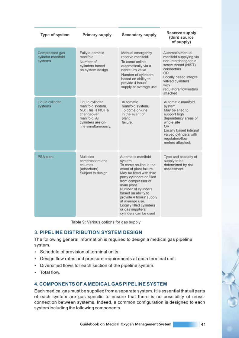

43Guidebook on Medical Oxygen Management System42 Guidebook on Medical Oxygen Management System
4.1 Sources
4.2 Piping networks
4.3 Valves
4.4 Warning and alarm systems
4.5 Outlets and inlets
4.6 Secondary equipment
These components explained as follows.
Figure14: Medical gas piping system configuration
mounted or pendant-mounted. The pipes should be made of high-quality copper,
seamless type, and non-arsenic. Moreover, it should be protected against physical
damage, corrosion and color coded as per gas content.
4.3 Valves
There are 2 types of valves, zone valves and service valves. Zone valves are used to
isolate large parts of the system, i.e. rooms for modification and/or repair. In addition, zone
valves are placed on corridor walls and should be labeled to indicate the rooms that they
control. On the other hand, service valves are used to isolate certain part of the system for
modification and/or repair. Accordingly, they are accessible by the clinical staff.
Copper seamless pipes with fluxless silver brazing are should be as per ASTM standard
and Lloyd's certification. They are intercepted by the area valve service units (AVSUs) and
area alarm panels (AAPs). In the following figures, AVSUs are placed in each clinical
sector, to cutoff the gas delivery to the area beyond it during maintenance or to handle
emergency. AAPs display the line pressures and have audiovisual alerts.
4.4 Warning and alarm systems
The function of warning and alarm systems is to give information for the responsible staff
about the whole plant in case of failure detection or change requirement. This includes the
sources, the pipes, the valves, etc. Therefore, there are 2 main alarm systems; master
alarms and area alarms. Master alarm monitors the main gas lines and sources
conditions. Area alarms are found on alarm panels and their function is to monitor the
conditions of specific critical care area.
4.5 Outlets and inlets
Outlets are points at which connections can be made to the medical gas piping system to
supply gases under pressure, while inlets are to supply vacuum.
These are the final delivery points are color coded, incorporating either the diameter index
safety system or are of the quick connect type, available in two varieties, the Diamond and
Chemetron in below figures. The Chemetron is a more sturdy variant and is resistant to
leakage.
4.6 Secondary equipment
Hoses, gas flow meters, gauges, and vacuum regulator. While these are not part of the
4.1 Sources
Sources are supplies that produce the flow of medical gases through piping networks.
There are four main sources for medical gases:
a. Bulky systems: They consist of special insulated vessels, vaporizers, and regulators.
These systems can be constructed with cryogenic vessels or a high-pressure manifold,
depending on the usage. Typically, oxygen, nitrous oxide, and carbon dioxide are supplied
to large hospitals in cryogenic tanks.
b. Manifold systems: It consists of high-pressure cylinders on 2 banks; one is a back-up to
the other. In addition, the main control panel is installed for primary and secondary
regulators, pressure regulators, and warning lamps.
c. Medical air treatment systems: Medical air treatment systems are usually 2 or more
compressors equipped with a receiver, derivers, regulators, filters, dew point monitors,
and carbon monoxide alarms. The air produced should be free of dust and moisture.
d. Vacuum pumps: Vacuum pumps are mechanized devices that create a negative
pressure in the piping system. The pumps should alternate automatically. A reservoir tank
is used for storage to permit cycling on and off instead of continuous operation. Each pump
should be capable of maintaining 75 per cent of calculated demand during peak time.
4.2 Pipeline Network
Medical gases and vacuum are distributed via the pipeline distribution system to provide
gas or vacuum at the endpoint or terminal units. The terminal units may be either wall-
Figure 15: Area valve service unit Figure 16: Area alarm panel

45Guidebook on Medical Oxygen Management System44 Guidebook on Medical Oxygen Management System
Figure 17: Diamond-type oxygen outlet point. Figure 18: Chemetron-type oxygen outlet point.
Figure 19: A set of medical gases outlets/inlets
Tests Procedures
Blowdown Lines are blown clear using oil-free dry nitrogen
Initial pressure test System is subjected to 1.5 times working pressureto check leaks
Standing pressure test System is subjected to 29% higher pressurefor 24hr
Piping purge Purging of each outlet until there is no discolorationof the white cloth held over it
Cross-connection test One gas system at a time using oxygen analyzer
Final tie-in testActive vacuum pipeline joints are tested usingas ultrasonic leak detector
Table 10: Pipeline testing
(Reference: Sarangi S, Babbar S, Taneja D. Safety of the medical gas pipeline system. J Anaesthesiol Clin
Pharmacol.https://www.joacp.org/text.asp?2018/34/1/99/227571)
6.1 Indigenous arrangement:
All critical areas should have bulk oxygen cylinders, fitted with a double-stage regulator,
tubing, and an adaptor. In case of manifold failure, the AVSU of the area is closed. The
pipeline beyond it can now be fed with oxygen from this cylinder, by connecting the adaptor
to any oxygen outlet point within the territory. Crisis due of vacuum pipeline failure can be
tided over with portable electrical suction units.
pipeline system, they can contribute substantially to gas and vacuum consumption. These
items should be checked as a part of routine inspection procedures.
5. PIPELINE DISTRIBUTION SYSTEM DESIGN
Ÿ Number of stations: The first step is to locate and count outlets/inlets, often called
"stations" for each specific gas type. There is no code that mandates the exact number
of stations in various areas of healthcare facilities. Therefore, this is usually done by the
medical planner or the architect based on requirements of the facility.
Ÿ Flow rates: Each station must provide a minimum flow rate to ensure proper functioning
of connected equipment. The flow rates and diversity factors vary for individual stations
depending on the total number of terminal units and the type of provided care. A
diversity or simultaneous-use factor is used to allow for the fact that not all of the
stations will be used at once. It is used to reduce the system flow rate in conjunction with
the total connected load for sizing mains and branch piping to all parts of the distribution
system. This factor varies for different areas of the facility. For example, diversity factor
for operating rooms and emergency rooms is 100 per cent, meanwhile for inpatient
rooms is 10 per cent. In general, minimum flow rates can be estimated for any pipe
section as: Oxygen- 200 L/min; Medical air- 200 L/min; Vacuum- 85 L/min; Nitrous
oxide- 28 L/min; Carbon dioxide- 28 L/min; Nitrogen- 425 L/min.
Ÿ Medical gases outlet/inlet terminals: Various types of medical gases outlet/inlet
terminals are provided from different manufactures. The terminals are available in
various gas sequence center-line spacing, and concealed mounting. It is more practical
to select terminals specifications with the adapters found on hospital's anesthesia
machines, flow meters, vacuum regulators, etc.
6. PIPELINE TESTING
Every new installation needs to be tested and verified as per the laid guidelines before
putting the system into use. It is important to have a contingency plan to avoid crisis
situations.
7. COLOR CODING FOR GAS PIPELINE
Lack of uniformity of colour coding of pipelines
in industrial installations has often been
responsible for destruction of property and
injury to personnel due to faulty manipulations
of values, particularly when outside agencies,
like fire-fighting squads, are called in. Colour
coding become more crucial in the hospital
setup where the life of the patients is on stake.
Uniformity of color marking promotes greater
safety, lessens the chances of error and
reduces hazards involved in the handling of
material inside the pipelines. The Indian
standard covers the colour scheme for the
identification of the contents of pipelines
carrying fluids and gases in domestic and
pub l ic bu i ld ings and such indust r ia l
establishments where a colour codes do not
exist.
Figure 20: Pipeline identification colours

47Guidebook on Medical Oxygen Management System46 Guidebook on Medical Oxygen Management System
For the purpose of this standard, piping systems shall include pipes of any kind and in addition fittings, valves, and pipe coverings. Supports, brackets or other accessories are specifically excluded from application of this standard. Identification of the particular contents of the pipelines is achieved by imposing suitable color bands on the ground colour. All pipelines should be color coded with colored bands put at intervals of every 3 meters.
• Ground Colour - The ground colour identifies the basic nature of the fluid and gasses
carried and also distinguishes one fluid/gas from another for example oxygen from
nitrogen, for the oxygen pipeline ground colour is canary yellow.
• Colour Bands- For the oxygen white colour band is used. Bands will be superimposed
on ground colour at the following locations,
- At battery unit points,
- Intersection points and change of direction points in piping ways.
- Other points such as midway of each piping way , near valves, junction points of
service appliances, walls on either side of pipe culverts,
- At the start terminating points
8. SAFETY AND HANDLINGSafety and handling of the MGPS system is covered under safety and handling chapter.
8.1. Duties of Manifold Operator
Ÿ First time in the morning, ensure that all the cylinders in the manifold room are OK.
Ÿ Open the number of cylinders to ensure the correct pressure in the pipelines.
Ÿ Using cylinders from one side of the manifold cylinders bank (right sight or left side)
Ÿ The cylinders of the other side should be sent for refilling as soon as all the cylinders of
that bank are empty.
Ÿ Check all cylinders for leakage using soap water mixture.
Ÿ Maintain a stock of required tools with him in the Manifold room.
Ÿ After checking the manifold room, take a round of the hospital to see all the outlets by
him, and to find out its proper functioning from staff posted there.
Ÿ Repair or arrange to repair any defects in the outlets or in the pipeline including Main
Manifold room.
Ÿ Place order for refilling of the cylinders in
consultation with the Authorized officer.
Ÿ Take care of the Nitrous cylinders in the
operation theatres if there is no central
supply of this gas. Ensure supply of
oxygen in other areas without central
pipeline.
Ÿ Help OT Technician in the maintenance
of the Boyle's machine.
Ÿ Changing the ward's cylinder is also his
duty.
Ÿ All the major problems are to be brought
to the administrators immediately.Figure 21: Oxygen Manifold System
1. BRIEF INTRODUCTION
An oxygen concentrator is a self-contained, electrically powered medical device designed
to concentrate oxygen from ambient air. Utilizing PSA technology, an oxygen concentrator
draws in air from the environment, extracts the nitrogen, and can produce a continuous
source of 95.5% concentrated oxygen.
Oxygen concentrators provide a safe source of oxygen-enriched air. Oxygen
concentrators (sometimes referred to as oxygen generators) are devices that draw room
air through a series of filters that remove dust, bacteria and other particulates. In the first
step of the concentration process, the machine forces air into one of the two cylinders
containing a molecular “sieve” material or semi-permeable membranes, where nitrogen is
absorbed, leaving concentrated oxygen (90% or higher) and a small percentage of other
gases found in room air. At the same time, in the other cylinder, nitrogen is desorbed and
drawn out into the atmosphere. In the second step, the function of the cylinders is reversed
in a timed cycle, providing a continuous flow of oxygen to the patient. A typical oxygen
concentrator may deliver oxygen flows of 0.5–5 LPM (low-flow oxygen concentrators),
while some models may generate up to 10 LPM (high-flow oxygen concentrators).
The clinical purpose of oxygen concentrator is to delivery of low-flow, continuous, clean
and concentrated oxygen (> 82%) from room air (21%). With appropriate accessories, two
or more hypoxaemic patients can be treated with one concentrator. The concentrators can
be used across all the levels of care including primary, secondary and tertiary levels.
Figure 22: Oxygen Concentrator
OXYGEN CONCENTRATORSC H A P T E R 5

49Guidebook on Medical Oxygen Management System48 Guidebook on Medical Oxygen Management System
1.1 Functional characteristics
Ÿ Contains oxygen monitor to verify concentration.
Ÿ Delivers oxygen through a nasal prongs or nasal catheter.
Ÿ Flow from one concentrator can be divided for at least two paediatric patients with
(built-in or add-on) flowmeters that allow continuous flow rate control.
Ÿ Requires continuous AC power source to operate, such as solar power, battery or
mains electricity ± backup (e.g. generator, UPS or battery).
(Maximum flow is chosen based on the expected patient load at any given time. Oxygen
needs vary per by patient and application. In general, up to 2 L/min per patient under 5
years of age is needed.)
1.2 Advantages and disadvantages
Evidence arising from both prospective and retrospective trials and randomised controlled
trials (with a minimum 12-month follow-up) suggests that oxygen concentrator use where
appropriate improves survival rates for respiratory conditions, improves mental
attentiveness, increases stamina and improves mood. The majority of studies have been
performed in patients with COPD and that the duration of oxygen supply per se affects
survival. In hypoxaemic chronic obstructive lung disease, continuous oxygen therapy is
associated with a lower mortality than is nocturnal oxygen therapy.
1.2.1 Advantages
Oxygen concentrators do not need to be refilled. The concentrators run on electrical power
and thus supply an unlimited amount of oxygen. Portable concentrators can be used in an
“on-the-go” mode with a battery pack, resulting in up to 12 h of continuous use for some
models. From a long-term view, concentrators are more cost-effective than compressed
gas cylinders, and they are known to last for up to 1500 h of continuous use.
1.2.2 Disadvantages
The significant disadvantage of oxygen concentrators is the need for electrical power to
function. It is necessary to prepare for unscheduled power outages by setting up a backup
power generator at home. Patients using stationary oxygen concentrators need to
consider changing filters weekly, regular servicing and the warm-up period of the machine,
as well as noise and vibration from the older models of device.
2. PREREQUISITE: PRE INSTALLATION REQUIREMENTS
Ÿ Verify plug electrical requirements with socket to be used.
Ÿ Clinical and staff training on device use.
Ÿ System for procuring spare parts.
2.1 Electrical connections
Ÿ Electrical source requirements to be locally compatible (voltage and plug type need to
be specified).
Ÿ Capacity for safe operation on at least ± 10% of local rated voltage.
Ÿ Mains power cable to have length ≥ 2.5 m.
Ÿ Electrical protection by resettable circuit breakers or replaceable fuses, fitted in both
neutral and live lines.
Ÿ Power backup in the form of UPS and inverters is suggested.
3. MAINTENANCE AND TROUBLESHOOTING
3.1 User care and preventive maintenance
3.1.1 User care
Ÿ Device exterior to be wiped effectively with a mild solution of detergent or cleaning
agent (weekly), without connection to mains power.
Ÿ Gross particle filter to be cleaned effectively when removed and washed with soap and
water (weekly).
Ÿ Do not clean with alcohol. (User care needed more often in very dusty environments.)
3.2 Corrective maintenance and troubleshooting of oxygen concentrator
Schedule Period Activities Check
Daily
Cleaning
Visual checks
Function
Remove any dust / dirt with damp cloth and dry off.Fill humidifier bottle up to marker with clean distilled water.
Check all screws, connectors, tubes and parts tightly fitted.
Check oxygen flow before clinically required.
Weekly
Cleaning
Visual checks
Function
Clean cylinder, valve and flowmeter with damp cloth.
Check for leakage: hissing sound or reduction in pressure.
Remove valve dust with brief, fast oxygen flow checks. Check flow can be varied using flow control.
Table 11: Preventive maintenance oxygen concentrators

51Guidebook on Medical Oxygen Management System50 Guidebook on Medical Oxygen Management System
Problem or fault Possible cause Solution
Unit notoperating,
powerfailure alarm
sounds
No power frommains socket
Concentrator circuitbreaker has been
set off.
Electrical cable fault
Check mains switch is on and cable inserted. Replace fusewith correct voltage / current if blown. Check mains power ispresent at socket using equipment known to be working.Contact electrician for repair if required.
Press reset button if present
Try cable on another piece of equipment.Contact electrician for repair if required.
Temperaturelight or low
oxygen alarm is on
Unit overheatedor obstructed
Remove any obstruction caused by drapes, bedspread, wall, etc. Clean filters. Turn unit off, using standby oxygensystem. Restart unit after 30 minutes. Call biomedical technician if problem not solved.
Unit notoperating, nopower failure
alarm
Alarm battery dead Replace battery and test as above
No oxygenflow
Flow not visible
Tubes notconnected tightly
Water or matterblocking the
oxygen tubing
Place tube under water and look for bubbles.If bubbles emerge steadily, gas is indeed flowing
Check tubing and connectors are fitted tightly
Remove tubing, flush through and dry out before replacing
Blocked flow meteror humidifier bottle
Replace meter / bottle or refer to biomedical technician
Electricalshocks
Wiring fault Refer to electrician
Table 12: Troubleshooting and corrective maintenance of oxygen concentrator
1. BRIEF INTRODUCTION
1.1 Purpose
Pulse oximeter is a portable, tabletop device intended for use in simultaneously
measuring, displaying and recording functional oxygen saturation of arterial hemoglobin
(Spo2) and pulse rate of adult and pediatric and neonatal patient. Oximetry refers to the
determination of the percentage of oxygen saturation of the circulating arterial blood.
In clinical practice, percentage of oxygen saturation in the blood is of great importance.
This saturation being a bio-constant (usually 95 to 100 percent in normal human being), is
an indication of the performance of the most important cardio-respiratory functions.
1.2 The main application areas of oximetry are
1. The diagnosis of cardiac and vascular anomalies.
2. The treatment of post-operative anoxia (absence of oxygen).
3. Treatment of anoxia resulting from pulmonary affections.
4. A major concern during anaesthesia is the prevention of tissue hypoxia (decrease in
oxygen level to tissues), necessitating immediate and direct information about the level of
tissue oxygenation.
5. Oximetry is now considered a standard of care in anaesthesiology and has significantly
reduced anaesthesia-related cardiac deaths.
6. Spot checking and/or continuous monitoring of patient during both motion and no-
motion conditions.
PULSE OXIMETERAND ACCESSORIES
C H A P T E R 6
Self-contained fingertip Portable handheld
Description
Portable device that has the
sensor, analyser and
display contained in a
single unit.
Handheld portable device
with display screen and
attached sensor probe and
cable.
Stationary device for
continuous
operation/monitoring. Some
can be wall- or pole-
mounted.
General Characteristics
Illustration
Tabletop

53Guidebook on Medical Oxygen Management System52 Guidebook on Medical Oxygen Management System
General Characteristics
Clinical application
and/or use case
Measurement of pulse rate
and SpO2 to detect
hypoxaemia, supporting the
diagnosis of respiratory
disorders. Almost always
designed for adults. Some
paediatric models can be
used on children (check
weight range for device),
but are not appropriate for
use in neonates.
Suitable for spot checks
only.
Measurement and/or
ongoing monitoring of pulse
rate and SpO2 to detect
hypoxaemia, supporting the
diagnosis of respiratory
disorders. Most, but not all,
will display a
plethysmography
waveform.
Suitable for spot checks, or
for continuous monitoring (if
used for continuous
monitoring, alarm feature
must be available and
activated, and device must
be regulatory approved for
continuous monitoring).
Monitoring of pulse rate,
SpO2 and plethysmography
waveform to detect
hypoxaemia, supporting the
diagnosis of respiratory
disorders.
Suitable for longer term
continuous monitoring.
Appropriate level of
health system (and areas
of use)
Primary, secondary and
tertiary level, but application
dependent, i.e. where spot
checking on adults (or
children, if a paediatric
model for an appropriate
weight range is used) is the
desired function.
Primary, secondary, tertiary,
e.g. health centres, general
medical and outpatient
areas, operating room, ICU,
neonatal intensive care unit
(NICU), recovery.
Secondary and tertiary, e.g.
general medical and
outpatient areas, operating
room, ICU, NICU, recovery.
Parametersmonitored
SpO2.
Pulse rate.
SpO2.
Pulse rate (some may have
additional features as RR).
SpO2.
Pulse rate (some may have
additional features).
Accessoriesrequired
Replacement batteries.
May have USB cable for
charging.
Probes; size specific to the
patient – adult, child, infant
and neonate (reusable
probes typically need
replacing at least once per
year). Replacement
batteries.
Charging/power cable.
Probes; size specific to the
patient – adult, child, infant
and neonate (reusable
probes typically need
replacing at least once per
a year).
Charging/power cable.
Low upfront cost.
Portable.
Self-contained unit; no
external probes/cables.
Multiple use-case options.
Portable.
More alarms and internal
memory than fingertip
devices. Typically, have ≥
12 hours' operational
capacity on rechargeable
built-in battery and take ≤ 4
hours to charge.
Ideally have a port (or Wi-
Fi) for downloading and/or
printing data.
Multiple use-case options.
May be pole mounted.
Large internal memory to
store patient IDs and
records.
Ideally have a port (or Wi-
Fi) for downloading and/or
printing data.
Most accurate, in general.
Merits
Self-contained fingertip Portable handheld Tabletop
Table 13: Types pulse oximeter
1.3 Controls on display
Ÿ Power/ standby button
Ÿ Spo2 alarm setting button
Ÿ Heart rate alarm setting button
Ÿ Set button (alarm, volume)
Ÿ Alarm silence button
1.4 The pulse oximeter probe
The oximeter probe consists of two parts, the light emitting diodes (LEDs) and a light
detector (called a photo-detector). Beams of light are shone through the tissues from one
side of the probe to the other. The blood and tissues absorb some of the light emitted by the
probe. The light absorbed by the blood varies with the oxygen saturation of hemoglobin.
The photo-detector detects the light transmitted as the blood pulses through the tissues
and the microprocessor calculates a value for the oxygen saturation (SpO2). In order for
the pulse oximeter to function, the probe must be placed where a pulse can be detected.
The LEDs must face the light detector in order to detect the light as it passes through the
tissues. The probe emits a red light when the machine is switched on; check that you can
see this light to make sure the probe is working properly. Probes are designed for use on
the finger, toe or ear lobe. They are of different types as shown in the diagram. Hinged
probes are the most popular but are easily damaged. Rubber probes are the most robust.
The wrap around design may constrict the blood flow through the finger if put on too tightly.
Ear probes are lightweight and are useful in children or if the patient is very
vasoconstricted. Small probes have been designed for children but an adult hinged probe
may be used on the thumb or big toe of a child. For finger or toe probes, the manufacturer
marks the correct orientation of the nail bed on the probe.
The oximeter probe is the most delicate part of a pulse oximeter and is easily damaged.
Handle the probe carefully and never leave it in a place where it could be dropped on the
floor. The probe connects to the oximeter using a connector with a series of very fine pins
that can be easily damaged, see diagram. Always align the connector correctly before
attempting to insert it into the monitor. Never pull the probe from the machine by pulling on
the cable; always grasp the connector firmly between finger and thumb.
Wrap around probe Hinged probe Rubber probes
Figure 23: Types of probes

55Guidebook on Medical Oxygen Management System54 Guidebook on Medical Oxygen Management System
Tips to protect oximeter probe
When not in use, the oximeter probe cable may be
loosely coiled for storage or carrying but should not be
coiled too tightly as this will damage the wires inside
the cable. The lens and detector should be kept clean.
Use soapy water or an alcohol-soaked swab to gently
clean dust, dirt or blood from the probe.
2. USER SET UP INSTRUCTIONS
After supply of the equipment ensure that it is open from the box and installed properly by
authorized company personnel.
2.1 Operating instructions
Ÿ Turn the pulse oximeter on: it will go through internal calibration and checks.
Ÿ Select the appropriate probe with particular attention to correct sizing and where it will
go (usually finger, toe or ear). If used on a finger or toe, make sure the area is clean.
Remove any nail varnish.
Ÿ Connect the probe to the pulse oximeter.
Ÿ Position the probe carefully; make sure it fits easily without being too loose or too tight.
Ÿ If possible, avoid the arm being used for blood pressure monitoring as cuff inflation will
interrupt the pulse oximeter signal.
Ÿ Allow several seconds for the pulse oximeter to detect the pulse and calculate the
oxygen saturation.
Ÿ Look for the displayed pulse indicator that shows that the machine has detected a
pulse. Without a pulse signal, any readings are meaningless.
Ÿ Once the unit has detected a good pulse, the oxygen saturation and pulse rate will be
displayed.
Ÿ Like all machines, oximeters may occasionally give a false reading - if in doubt, rely on
your clinical judgement, rather than the machine.
Ÿ The function of the oximeter probe can be checked by placing it on your own finger.
Ÿ Adjust the volume of the audible pulse beep to a comfortable level for your theatre –
never use on silent.
Ÿ Always make sure the alarms are on.
3. MAINTENANCE AND TROUBLESHOOTING OF PULSE OXIMETER
3.1 Maintenance and preventive Care
Ÿ Regularly clean the pulse oximeter so as to prevent accumulation of dust and other
hospital fluids on the body of the pulse oximeter.
Ÿ Ensure protection from bright lights.
Ÿ Keep a patient away from devices inducing electromagnetic fields like MRI, CAUTERY
machine etc.
Ÿ Check cable and equipment for any external damages.
Ÿ Fold the SpO2 cable properly and do not pull the sensor.
Ÿ Clean reusable sensors with spirit after each patient use
Figure 24 :Coiled Probe Cable
3.2 Troubleshooting of Pulse oximeter
Problem Possible cause Solution
Battery is completelydischarged
Battery is notgetting charged
Charge the batteries for 6 hours by connecting to the AC mains.
Oximeter will not power up
Sensor or patient cableis disconnected fromthe oximeter
Check sensor patient cable connections
No pulse shownon the barograph
Sensor isincorrectly positionedon the patient
Reposition the sensor
Poor patient perfusion Reposition the sensor
Defective sensoror patient cable
Try a new sensor or patient cable or contact our dealer.
Defective LEDdisplays
Contact service provider for repairs.Segments of
SPO2 or pulserate missing
Check the AC mains socket for proper voltage.Check for Green LED on OximeterIf Green LED does not light, contact our dealer-circuit problemIf Green LED lights up, contact our dealer -battery needs replacement
Excessive motionat sensor site maybe prohibiting theoximeter from acquiring a consistent pulse signal
Eliminate or reduce cause of motion artefact OR reposition sensor tonew sensor site where motion is not present.
Displayed pulserate does notcorrelate withpulse rate onECG monitor
ECG monitor maynot be functioningproperly.
Examine the patient: Replace ECG monitor OR refer tooperator's manual of ECG monitor
Patient may have arrhythmia resulting in some heart beatsthat do not yield a perfusion signal at sensor site
Examine the patient: condition may persist even though both themonitors are functioning properly if patient's arrhythmia persists.
ESU may beinterfering withoximeter performance
Examine the patient:Move oximeter, cables and sensor as far away from ESUas possible OR refer to the ESU operator's manual
Erratic pulsedisplay and/or
yellow perfusionLED during
concurrent useof electrosurgicalequipment (ESU)
Perfusion signal atsensor site is marginal
Examine the patient: Reposition sensor OR selectalternate sensor site
Perfusion isblinking yellowwith each pulse

57Guidebook on Medical Oxygen Management System56 Guidebook on Medical Oxygen Management System
Problem Possible cause Solution
Low patient pulsestrength sensor sitepoorly perfusedsensor not correctlypositioned. Excessivecold condition
Reposition sensor on patient
Sensor attached tootightly or tape isrestricting perfusionat sensor site
Reposition sensor, select alternate site or remove restrictivematerial from sensor site
Circulation reduceddue to excess pressurebetween sensor andhard surface
Allow sensor and finger to rest comfortably on surface
Excessiveambient light
Reduce ambient light
Excessivepatient motion
Reduce patient motion OR select alternate sensor site
Sensor applied topolished fingernail
Remove fingernail polish
Reduce or eliminate interference
Interference from:arterial catheterblood pressure cuffelectrosurgical procedureinfusion line
Unable to obtaingreen perfusion
Inadequate perfusionsignal at sensor site
Excessive motionat sensor site may beprohibiting the oximeterfrom acquiring aconsistent pulse signal
Examine the patient:Reposition sensor OR select alternate sensor site
Eliminate or reduce cause of motion artefact ORreposition sensor to new sensor site where motion is not present
Perfusion LEDis blinking red
Sensor problemCheck sensor connection to oximeterCheck proper connection to patientSensor faulty-needs replacement
Sensor alarmsound
continusly
Alarm limitviolation due tofaulty alarm limits
Reset the alarm limits OR Reset the oximeterto factory default settings
Alarm soundscontinuously
Unit not detectingoximeter modulefaulty sensor-Tryreplacing sensor
Contact your dealer for repairsError "OximeterNot Installed"
Table 14: Common problems and remedies of pulse oximeter
3.3 Do's and Don'ts
a. Do's
Ÿ Inspect sensor site every 2 to 4 hours for any erythema (reddish ness of patient
skin) or discoloration.
Ÿ Change sensor site every 4-6 hours.
b. Don'ts
Ÿ Do not apply sensor too tightly.
Ÿ Do not apply probe to edematous (edema- accumulation of fluid beneath skin) and or
bruised sites
Ÿ Do not autoclave, pressure sterilize or gas sterilize.
Ÿ Do not soak or immerse the pulse oximeter in liquid.
Ÿ When cleaning the display area do not use abrasive cleaning compounds or other
materials that could damage the screen.
Ÿ Do not use petrol based solutions, acetone solutions or other harsh solvents to
clean the pulse oximeter.
3.4 Fast moving spares and accessories
Ÿ Electrical fuses.
Ÿ Sensor probe.
3.5 Bare minimum tools required
Ÿ Screw driver for fuse replacement.

58 Guidebook on Medical Oxygen Management System
1. BRIEF INTRODUCTION
1.1 Devices for oxygen regulation and conditioning
The oxygen therapy products covered in this section include flowmeters, flow-splitting
devices and humidifiers. These devices play different roles in the regulation and
conditioning of oxygen gas for the delivery of oxygen therapy to patients.
1.1.1 Flow meter
In oxygen therapy systems, flowmeters are needed to measure and control the rate of
oxygen flow to patient, either from a concentrator, a high-pressure cylinder, or a terminal
unit of a piped system.
Concentrators have built-in flowmeters so there is no need to purchase them separately.
When using oxygen sources with varying pressures (e.g. oxygen cylinders or terminal
units), it is important that flowmeters are placed on the low-pressure side, downstream of a
pressure-reducing valve.
Three types of gas flowmeters are described in this overview: Thorpe tube, Bourdon
gauge and dial/click. All three types come in various flow ranges. The choice of appropriate
flowmeter will depend on clinical needs and device capabilities. Below mentioned table
provides a comparison of these three device types.
Thorpe tube(rotameter)
Bourdon gauge(single and multiple stage)
Dial/click (flow restrictor)
Illustration
A variable orifice flowmeter
consisting of an upright clear
tube contains a float, which
rises and falls in relation to
gas flow. There are two
types: uncompensated and
compensated for back
pressure. Requires a
separate pressure-reducing
valve.
In a fixed orifice flowmeter gas
enters a chamber and as the
pressure is increased, a coiled
copper tube straightens out
and the needle valve turns to
read a higher unit. This device
integrates with a pressure-
reducing valve.
fixed-orifice flowmeter
calibrated to deliver flow
in specific increments,
adjusted with a click dial.
This device integrates a
pressure-reducing
valve.
General characteristics
Description
DEVICES FOR OXYGENDELIVERY, REGULATION AND
CONDITIONING
C H A P T E R 7

59Guidebook on Medical Oxygen Management System
For all inpatient clinical areas in health care facilities where oxygen therapy is provided.Recommended for use with terminal units (wall outlets) of piped distribution systems orfor large stand-alone cylinders.
Ideal for ambulancetransportation. Recommendedfor use with smaller portable cylinders common for emergency and ambulancetransportation.
For all inpatient clinical areas in health care facilities where oxygen therapy is provided(terminal units – either wall outlets or ceiling mount drops of piped oxygen distributionsystems in hospitals). Also common with portable cylinders for intra facility, interfacility or air transport.
Clinical application
and/oruse case
Product-specific characteristics
No No Yes
Integrates apressure-reducing
valve
Always attached to a 345kPa (3.45 bar,50 psig) source.
Variable. Variable.Inlet pressure
Terminal unit (wall outlet)or cylinder with pressure-reducing valve.
Cylinder.Terminal unit (wall outlet or ceiling mount drop),or cylinder.
Oxygen source
Simple. Cost-effective. Wide variety of flow ranges available. Provides visual feedback of actual flow measurement.Can fine-tune flow rate.Pressure compensated: flow is accurate in the face of an obstruction downstream.
Unaffected by gravity;works in any position.Inbuilt with regulatorand gauge.
Simple to operate.Unaffected by gravity;works in any position.Inbuilt with regulator and gauge.Compact.Merits
Affected by gravity; works in a vertical position only.Needs additional pressure regulator and gauge. Fragile.Uncompensated: candisplay an erroneouslyhigh flow rate.
Not back pressurecompensated.As flow increases, theindicated flow readingbecomes inaccurate.
Can only choose flow rates in fixed increments.Regulates but does not measure flow.Expensive.Accurate only at ratedpressure.
Drawbacks
Thorpe tube flowmeter has following variants -
a) Pressure regulator and outlet connector (e.g., DISS) (male). Connector (DISS or
other convention) can be connected to flowmeter.
b) A barbed “Christmas tree” connector for oxygen tubing.
c) A humidifier bottle.
d) An example of a dual flowmeter from a single wall source for use with two patients.
Table 15: Description and comparison of flowmeters
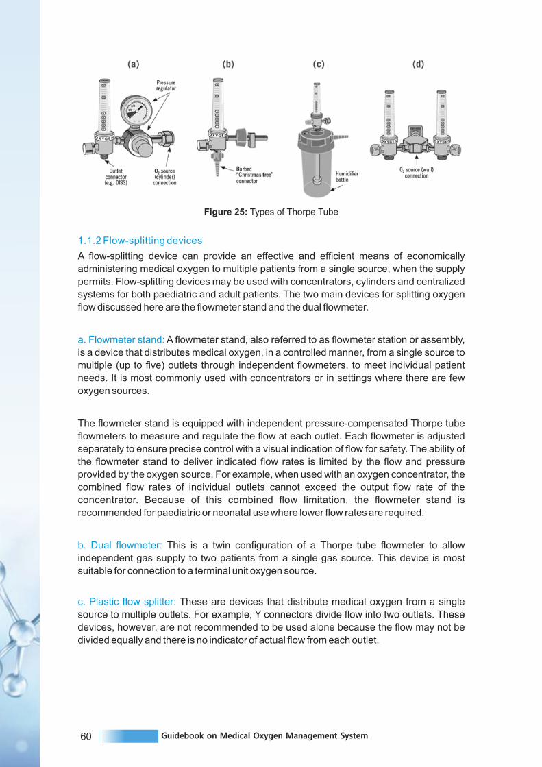
60 Guidebook on Medical Oxygen Management System
1.1.2 Flow-splitting devices
A flow-splitting device can provide an effective and efficient means of economically
administering medical oxygen to multiple patients from a single source, when the supply
permits. Flow-splitting devices may be used with concentrators, cylinders and centralized
systems for both paediatric and adult patients. The two main devices for splitting oxygen
flow discussed here are the flowmeter stand and the dual flowmeter.
a. Flowmeter stand: A flowmeter stand, also referred to as flowmeter station or assembly,
is a device that distributes medical oxygen, in a controlled manner, from a single source to
multiple (up to five) outlets through independent flowmeters, to meet individual patient
needs. It is most commonly used with concentrators or in settings where there are few
oxygen sources.
The flowmeter stand is equipped with independent pressure-compensated Thorpe tube
flowmeters to measure and regulate the flow at each outlet. Each flowmeter is adjusted
separately to ensure precise control with a visual indication of flow for safety. The ability of
the flowmeter stand to deliver indicated flow rates is limited by the flow and pressure
provided by the oxygen source. For example, when used with an oxygen concentrator, the
combined flow rates of individual outlets cannot exceed the output flow rate of the
concentrator. Because of this combined flow limitation, the flowmeter stand is
recommended for paediatric or neonatal use where lower flow rates are required.
b. Dual flowmeter: This is a twin configuration of a Thorpe tube flowmeter to allow
independent gas supply to two patients from a single gas source. This device is most
suitable for connection to a terminal unit oxygen source.
c. Plastic flow splitter: These are devices that distribute medical oxygen from a single
source to multiple outlets. For example, Y connectors divide flow into two outlets. These
devices, however, are not recommended to be used alone because the flow may not be
divided equally and there is no indicator of actual flow from each outlet.
Figure 25: Types of Thorpe Tube

61Guidebook on Medical Oxygen Management System
Flowmeter stand Dual Flowmeter
Illustration
A device that distributes medical oxygen by splitting output flow from a single oxygen source to multiple outlets through independently regulated flowmeters, to individual patient needs.
A device that distributes medical oxygen by splitting output flow from a terminal unit (wall outlet) oxygen source through two independently regulated flowmeters, to meet individual patient needs.
General characteristics
Description
Splitting oxygen flow for inpatient oxygen therapy, particularly paediatric or neonatal wards where lower flow rates are used. One inlet can be divided into several independently regulated outlets for up to five patients. Set flow rates cannot exceed output flow rate of the concentrator.
Splitting oxygen flow for inpatientoxygen therapy. One inlet can be divided into two independently regulated outlet for up to two patients.
Clinicalapplication
and/oruse case
Primary, secondary, tertiary (anywhereoxygen therapy is provided; health centre, general hospital, district hospital, provincial hospital, regional hospital, specialized hospital).
Secondary, tertiary (requires pipedterminal unit).
Appropriatelevel of health
system(and relevantmedical units)
Product-specific characteristics
Yes; via the mounted flowmeters. Flow regulation Yes; via the two flowmeters.
Oxygen source Terminal unit of centralized piped system.
Merits
Simple.Can serve multiple patients who need oxygen therapy at different flow rates. Can be securely mounted to a terminal unit within easy reach of health care workers and without disturbances. Flowmeters are generally easy for health care workers to read. Suitable for primary care settings withoutcentralized piped oxygen.
Simple. Can serve two patients who need oxygen therapy at different flow rates. Can be securely mounted to a terminal unit within easy reach of health care workers and without disturbances. Less costly than flowmeter stand, in general.Easier installation.
Drawbacks
Costly. Require space for health care workers to easily access the flowmeters. Usually mounted in a fixed position, which may restrict where patients can be placed. A clear outlet-to-bedside identification system must be established, otherwise there can be confusion about which outlet serves which bedside.
Requires centralized piped systemand terminal unit adapter (which is notavailable in many primary care settings). Can only divide flow for up to two patients.
Concentrator or cylinder (on the downstreamside of a pressure regulator at 345 kPa (3.45 bar, 50 psig)).
Table 16: Description and comparison of flow splitting devices

62 Guidebook on Medical Oxygen Management System
1.1.3 Humidifiers
a. Oxygen humidifiers: These are medical devices that can be integrated into oxygen
delivery systems to humidify supplemental oxygen. Humidification is generally not
necessary when oxygen is delivered at relatively low flow rates through nasal prongs or
nasal catheters. When oxygen is delivered at higher-than-standard flow rates, or when
methods of oxygen delivery bypass the nose, such as when nasopharyngeal catheters are
used, humidification is needed – especially when cold oxygen is delivered from a cylinder.
There are various types of humidifiers, and their designs differ in how they apply three
main principles related to humidification:
b. Temperature: As the temperature of gas increases, its ability to hold water vapour
increases.
c. Surface area: There is more opportunity for evaporation to occur due to greater surface
area of contact between water and gas.
d. Time of contact: There is more opportunity for evaporation to occur when a gas remains
in contact with water for long duration.
Bubble humidifier –Non heated (reusable)
Bubble humidifier –Non heated (single use)
Bubble humidifier – heated
Illustration
A reusable bottle thatreduces the dryness ofoxygen by bubbling the gas through distilled water (or water that has been boiled and cooled) at room temperature.
A single-use bottle thatreduces the dryness ofoxygen by bubbling the gas through distilled water at room temperature.
A device consisting of aheat source and ahumidification chamberwhereby the built-in heater warms the water in the chamber to add moisture to the airstream as it passes over the surface.
General characteristics
Description
Reduces drying of the nasal passages during oxygen therapy. Used when oxygen is delivered at higher-than-standard flow rates, or when methods of oxygen delivery bypass the nose, such as when asopharyngeal catheters are used.
Clinicalapplication
and/oruse case
Heated humidification is needed for CPAP and for HFNC oxygen therapy.
Primary, secondary and tertiary level.
Appropriate levelof health system
(and relevantmedical units)
Secondary andtertiary level.

63Guidebook on Medical Oxygen Management System
Bubble humidifier –Non heated (reusable)
Bubble humidifier –Non heated (single use)
Bubble humidifier – heated
Adjustable heat for moreor less moisture. More efficient athumidifying gas.
Product-specific characteristics
Merits
Simple. No power required. Low cost. Reusable.
Risk of “rainout”. High risk of contamination(reduced by changing thewater frequently).Needs power source.
Drawbacks
Generalcomments
Works best at a watertemperature of at least 30 °C.
Simple. No power required. Low cost. Reusable.
Disposable/single-use. More costly.
High risk of contamination (reduced by changing the water frequently) Decontamination required.
Works best at a watertemperature of at least 30 °C.
Works best at a watertemperature of at least 37 °C.
2. OXYGEN DELIVERY DEVICES
This section describes the devices that connect an oxygen source to a patient, for the
delivery of oxygen therapy. These delivery methods can be used regardless of what
source of oxygen is used (cylinder, concentrator or piped system).
Devices for oxygen delivery differ in cost, efficiency of oxygen use, and ability to provide
the requisite fraction of inspired oxygen (FiO2) (i.e. the percentage or concentration of
oxygen that a patient inhales). The choice of appropriate delivery device will thus depend
on clinical needs and device capabilities.
Nasal Cannula (prongs) Nasal CatheterOther noninvasive options
(face mask, head box,incubator, tent)
Illustration
Plastic tubes that end in twoshort, tapered prongs thatare placed in the nostrils.
Thin, flexible tube that ispassed into the nose andends with its tip in thenasal cavity.
Various non-invasivemethods of oxygen delivery are available, including head boxes, face masks (simple, partial rebreathing and non rebreathing), incubators and tents.
General characteristics
Description
Low-flow oxygen therapy for the treatment of hypoxaemia.
Low-flow oxygen therapy for the treatment of hypoxaemia.
Applications where FiO2needs to be tightly controlled.Typically, higher flows arerequired to achieve adequateconcentration of oxygen andprevent carbon dioxideaccumulation.
Clinicalapplication
and/oruse case
Table 17: Description and comparison of humidifiers
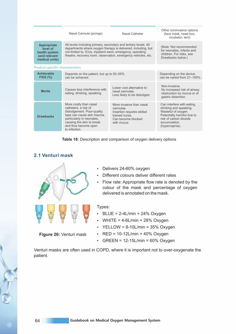
64 Guidebook on Medical Oxygen Management System
Appropriatelevel of
health system(and relevantmedical units)
(Note: Not recommended for neonates, infants and children. For risks, seeDrawbacks below.)
Non-invasive. No increased risk of airwayobstruction by mucus or ofgastric distention.
Product-specific characteristics
MeritsCauses less interference witheating, drinking, speaking.
Lower cost alternative tonasal cannulae.Less likely to be dislodged.
Can interfere with eating,drinking and speaking. Wasteful of oxygen. Potentially harmful due to risk of carbon dioxideaccumulation(hypercapnia).
Drawbacks
More costly than nasalcatheters. a risk ofdislodgement. Poor-qualitytape can cause skin trauma,particularly in neonates,causing the skin to breakand thus become opento infection.
More invasive than nasalcannulae. Insertion requires skilledtrained nurse. Can become blockedwith mucus
Depends on the patient, but up to 50–55%can be achieved.
AchievableFiO2 (%)
Depending on the device,can be varied from 21–100%.
All levels including primary, secondary and tertiary levels. All departments where oxygen therapy is delivered, including, but not limited to, ICUs, inpatient ward, emergency, operating theatre, recovery room, observation, emergency vehicles, etc.
2.1 Venturi mask
Ÿ Delivers 24-60% oxygen
Ÿ Different colours deliver different rates
Ÿ Flow rate: Appropriate flow rate is denoted by the
colour of the mask and percentage of oxygen
delivered is annotated on the mask.
Types:
Ÿ BLUE = 2-4L/min = 24% Oxygen
Ÿ WHITE = 4-6L/min = 28% Oxygen
Ÿ YELLOW = 8-10L/min = 35% Oxygen
Ÿ RED = 10-12L/min = 40% Oxygen
Ÿ GREEN = 12-15L/min = 60% Oxygen
Venturi masks are often used in COPD, where it is important not to over-oxygenate the
patient.
Figure 26: Venturi mask
Nasal Cannula (prongs) Nasal CatheterOther noninvasive options
(face mask, head box,incubator, tent)
Table 18: Description and comparison of oxygen delivery options

65Guidebook on Medical Oxygen Management System
3. OXYGEN ANALYSERS
Oxygen analysers, also referred to as oxygen monitors, are devices that measure and
display the concentration of oxygen in patient breathing circuits, medical gas supply lines,
compressed gas cylinders and oxygen concentrators. They are also used to check and
adjust devices used to administer oxygen to patients.
Some oxygen analysers are designed to continuously measure oxygen concentration
inhaled by a patient in a respiratory therapy setting (e.g.,in an anaesthesia or ventilator
breathing circuit, infant oxygen hood, or oxygen therapy system tubing). Oxygen
analysers can also be built into ventilators or anaesthesia units, where the oxygen sensor
is automatically enabled when the system is in use. In a continuous patient monitoring
application, an alarm is required to alert clinical personnel when the oxygen concentration
reaches a dangerous level or goes beyond a predetermined range.
Other analysers are intended to perform routine oxygen spot checks either at the oxygen
source (e.g. an oxygen concentrator), in the environment (e.g. oxygen hood) or during
equipment maintenance. In this case, alarms may not be necessary. In this chapter, the
focus is on such portable handheld analysers that a biomedical engineering technician or
health worker could use to test the concentration of oxygen from a concentrator or the low-
pressure side of a compressed gas cylinder or terminal unit source.
Oxygen analyzer for testingconcentration-
Electrochemical
Oxygen analyzer fortesting concentration-
Ultrasonic
Multiparameter analysers(Concentration, flow and
pressure)
Illustration
A device that measures
and displays oxygen
concentration using
electrochemical sensing
technology.
A device that measures
and displays the oxygen
concentration using
ultrasonic oxygen sensing
technology.
A device designed to test
all types of gas flow
equipment especially
those requiring high
accuracy.
General characteristics
Description
Can be used for continuous
monitoring and for spot
checking at an oxygen
source or in an environment.
All clinical departments that
use oxygen should have an
analyser and use it regularly.
Spot checking and servicing
of PSA-generated oxygen,
from concentrators.
All clinical departments that
use concentrators should
have an analyser and use it
regularly.
Equipment spot
checking and servicing.
Clinicalapplication
and/oruse case
Primary, secondary, tertiary. Secondary, tertiary. Primary, secondary, tertiary. Appropriate
level of health system
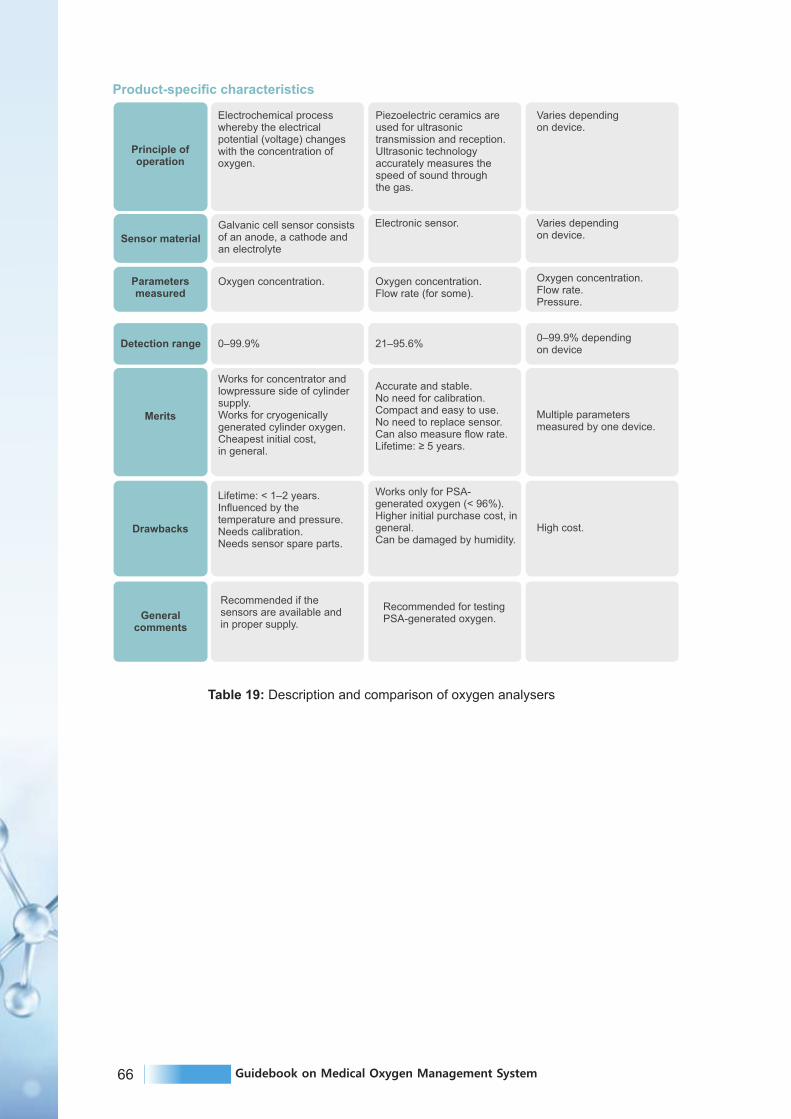
66 Guidebook on Medical Oxygen Management System
Varies dependingon device.
Product-specific characteristics
Principle ofoperation
Electrochemical processwhereby the electricalpotential (voltage) changeswith the concentration ofoxygen.
Piezoelectric ceramics areused for ultrasonictransmission and reception. Ultrasonic technologyaccurately measures thespeed of sound throughthe gas.
Varies dependingon device. Sensor material
Electronic sensor.
Oxygen concentration.Flow rate.Pressure.
Parametersmeasured
Oxygen concentration. Oxygen concentration.Flow rate (for some).
0–99.9% dependingon device
Detection range 0–99.9% 21–95.6%
Multiple parametersmeasured by one device.
Merits
Works for concentrator andlowpressure side of cylindersupply.Works for cryogenicallygenerated cylinder oxygen.Cheapest initial cost,in general.
Accurate and stable.No need for calibration.Compact and easy to use.No need to replace sensor.Can also measure flow rate.Lifetime: ≥ 5 years.
High cost.Drawbacks
Lifetime: < 1–2 years.Influenced by thetemperature and pressure.Needs calibration.Needs sensor spare parts.
Works only for PSA-generated oxygen (< 96%).Higher initial purchase cost, in general.Can be damaged by humidity.
Generalcomments
Recommended if thesensors are available andin proper supply.
Recommended for testingPSA-generated oxygen.
Galvanic cell sensor consists of an anode, a cathode and an electrolyte
Table 19: Description and comparison of oxygen analysers

67Guidebook on Medical Oxygen Management System
Mechanical ventilator is an apparatus which can
replace normal mechanism of breathing either by
providing intermittent or continuous flow of oxygen or air
under pressure, which is connected to the patient by a
tube inserted through mouth, the nose or an opening in
the trachea.
Mode
Mode is the set up or level that characterises and
modifies the manner in which oxygen is delivered to the
patient.
Ÿ Types of non-invasive mode
- BIPAP Mode
- C PAP Mode
Ÿ Types of invasive mode
- Controlled
- Supportive
- Combination
Ventilator equipment maintenance includes cleaning,
sterilization, adjustment, servicing, and repair.
Minor maintenance procedures can be done at the
hospital by a biomedical engineer, as per instructions by
the manufacturer. For major repairs, it is suggested to
have a maintenance and repair check through the
biomedical engineer allocated by the manufacturer.
This is the way to achieve ideal working conditions and
to enhance reliability and durability of the equipment. It
is obvious that regular servicing is better than
expensive repairs and is less costly in the long run. Both
systems working together would be more efficient, but
this is difficult to achieve because of the restrictions in
personnel.
Transport, portable
Ventilator
4. VENTILATORS
Figure 27 :
Types of ventilators
CPAP & BiPAP
CPAP and BiPAP machines are both forms of positive
airway pressure therapy, which uses compressed air to
open and support the airway during sleep. A portable
machine generates pressurized air and directs it to the
user's airway via a hose and mask system. Both
systems use the same masks, hoses, and other
accessories.
Figure 28 : CPAP /
BiPAP machine
Intensive care
68 Guidebook on Medical Oxygen Management System
4.1 CPAP
Continuous airway pressure machines direct pressurized air — usually set between 4 and
20 cm H2O - into a user's airway while they sleep. This pressure keeps air passages open
and ensures the user can breathe properly, allowing them to avoid the pauses in breathing
(or apneas) that are the primary symptom of sleep apnea.
CPAP machines continuously pump air at one pressure setting rather than varying in
pressure between the inhale and exhale, which can cause some people to feel as though
they cannot exhale properly or that they are choking. Most users adjust to CPAP relatively
quickly, while others find BiPAP easier to tolerate.
Unlike BiPAP machines, CPAP machines are available in a range of sizes. The most
common type is intended to be used at home and is slightly smaller than a shoebox, while
travel versions may be small enough to fit in the palm of your hand. Travel models
sometimes have backup batteries for use while camping, and FAA-approved models are
available for use on planes.
4.2 BiPAP
Bi-level positive airway pressure machines have two air pressure settings: one for the
inhalation phase (IPAP), and one for exhalation (EPAP). The EPAP is usually significantly
lighter than the IPAP, allowing users to breathe more naturally and not experience
resistance from the machine during exhale. Most machines have a range of approximately
4 to 25 cm H2O, 5 cm H2O higher on the upper end than CPAP machines.
BiPAP machines have up to three settings for the switch between IPAP and EPAP:
1. Spontaneous switching automatically senses the user's breathing pattern and switches
between the two pressure levels when they naturally inhale and exhale. The majority of
BiPAP users rely on this setting, and it is standard for BiPAP devices.
2. Timed switching allows users to program how long each IPAP and EPAP phase should
last. This ensures users take the correct number of breaths per minute and can function
much like a ventilator.
3. Spontaneous/timed switching is primarily spontaneous, following the user's natural
breathing patterns. On this setting, timed switching turns on when the machine senses
that the user has dropped below a set number of breaths per minute.

69Guidebook on Medical Oxygen Management System
1.1 OXYGEN CALCULATION
1.1.1 Oxygen Calculator Purpose
Ÿ Evaluating the capacity of oxygen available in the hospital.
Ÿ Determine total litre per minute requirement in normal circumstances.
Ÿ Estimate oxygen supply balance.
Ÿ Used as an estimation tool during oxygen weaning protocol implementation.
Ÿ Helps understand complex conversion from Metric Ton to Kilo Litres, Kilo Litres of liquid
oxygen to gaseous state of oxygen.
Ÿ Will assist auditors to fill audit forms compiled by Government of Maharashtra and other
governance.
Ÿ Factors amount of oxygen required through in LMO Tanks.
Ÿ Factors amount of residual oxygen in dura & jumbo cylinders.
Ÿ Manages the safety factor and determines the period for which the oxygen supply
would last. Keeps safety factor and arrives at when oxygen supply should last.
1.1.2 Oxygen Calculator - Points to Remember
If oxygen supply utilization time in the hospital practically differs from the time determined
using the calculator calculator, it could be due to the following reasons:
Ÿ There could be leakages
Ÿ Oxygen weaning protocol is not properly practiced
Ÿ Pressure settings in the hospitals are wrong
a. Oxygen Supply Process and Delivery Conversion
Ÿ Oxygen is supplied by manufacturers to hospitals in cryogenic form and is measured in
metric tons.
Ÿ Oxygen is moved to LMO tank, it is measured in litres or kilo litres.
Ÿ Oxygen is delivered to patients in gaseous form in litres per minute via oxygen points.
b. Oxygen Supply Process and Conversion Calculation
Conversions3
Ÿ 1 CuM (m ) = 1,000 liters (Gaseous O )2
3Ÿ 1 Metric Ton (MT) = 770 CuM (m ) = 7,70,000 liters (Gaseous O )2
Ÿ 1 Metric Ton (MT) = 876 litres of Liquid Oxygen
Ÿ 1KL Liquid O2 = 877.8 CuM
Ÿ 1 Litre Liquid O2 = 861 litres of gaseous O2
INVENTORY MANAGEMENTC H A P T E R 8

70 Guidebook on Medical Oxygen Management System
1. Gaseous oxygen litres to cubic meters (m3) to metric ton (MT)
2. Gaseous Oxygen LPM (liter per min) to MT/day
3. Converting kilo liter (KL) (Liquid oxygen) to metric ton (MT)
Ref: Unit Conversion Data for Oxygen. Universal Industrial Gases Inc. Accessed at
http://www.uigi.com/o2_conv.html in December 2020.
Qty in liter of gas Qty in CuM Qty in kg Qty in MT
1000 1 1.429 0.001429
Qty in MT per day(Qty in kg / 1000)
Qty in kg per day(Litres of gas x 0.001429)
Qty in liter of gas per day(LPM x 60 mins x 24 hours)
1 LPM 2.05776 0.00205776
100 LPM
1440
205.77600 0.20577600
500 LPM 720000 1028.88000 1.02888000
1000 LPM 1440000 2057.76000 2.05770000
144000
Qty in litresof liquid oxygen
Qty in KL Qty in kg Qty in MT
Directly formliquid oxygen to MT
1 1.14171000 1141.7

71Guidebook on Medical Oxygen Management System
A B C D
1
2
Oxygen beds Oxygen flowrate(LPM)
100 10 litres/min
Oxygenrequirement per day
in Cubic meter
Total oxygenrequirement
60 minutes x 24 hrs/1000 (to convert
3litres to m )
"X"=Column(A*B*C)e. g. 100 x 10 x 60
x 24 /1000 = 31440 m
Total requirementof the State for
3Oxygen in m fordedicated COVIDfacilities=”X+Y”
(e. g. 1440 + 21603= 3600 m )Oxygen requirement for ICU beds in DCH facilities
ColumnNo
F G H I
Sr No
1
ICU bedsOxygen flowrate
(LPM)
50 30 litres/min
Oxygenrequirement per day
in Cubic meter
Total oxygenrequirement
60 minutes x 24 hrs / 1000 (to convert
3litres to m )
"Y"=Column(F*G*H)(e. g. 50 x 30 x 60 x
3 24 /1000 = 2160 m )
Note: Flow rate of 10 LPM/O2 bed and 30 LPM/ICU bed are considered for consumption calculation as per latest GoI guideline D.O.No. T-20017/03/2021-NCD (FTS- 8110554) dated 21st June 2021. These flow rates are subject to change depending on revised guidelines from GoI.
*As per the state trend/average total 12% of total active cases need medical oxygen support out of which 8% on O2 beds and 4% on ICU beds. District/Facility can use the actual percentage as per their patient data on oxygen support requirement.
ColumnNo
Oxygen requirement for oxygen beds (excluding ICU beds) in Dedicated COVID Hospital (DCH) and Dedicated COVID Health Centre facilities (DCHC)
1.2 Oxygen Requirement/Consumption based on bed strength
ColumnNo
A B C D E F G
Sr No Active cases
O2 supportedbeds required(8%* active
cases)
ICU beds O2requirement
required (4%*active cases)
Total Oxygenconsumption
(In CubicMeters) @ 10LPM flowrate
ICU bedsoxygen
consumption@ 30 LPM
flowrate
Total Oxygenconsumption
(Cubic Meters)
Total OxygenConsumption
on (MT)
XColumn no "A"*8/100
Columnno "A"*4/100
Column no"B"*10*60*
24/1000
Column no "C"*30*60*
24/1000
Column no"D+E"
Column no"F/770"
10001000*8/100=80
1000*4/100=40
80*10*60*24/1000=
1152
40*30*60*24/1000=
1728
1152 + 1728= 2880
2880 /770 = 3.74
e. g
1.3 Daily Oxygen Consumption/requirement Based on Active Cases
Table 20: Oxygen requirement/consumption based on bed strength
Table 21: Daily oxygen requirement/consumption based on active cases

72 Guidebook on Medical Oxygen Management System
Gaps to be addressed for Oxygen Supply3Gap in O Supply = Total Oxygen Required (X+Y) - Total availability (A+B+C+D+E) in m2
(Reference: Oxygen requirement, availability, and Gap analysis MOHFW, D.O. Letter dated 18th April 2020)
Imp. Note: The use of oxygen cylinders requires three times the inventory of cylinders
consumed in a hospital on a single day (one set of cylinders in use, one set as backup and
one set in refilling station).
Source of Oxygen in dedicated
COVID Hospitals (DCHC & DCH)Calculation for O2 Total
D Type (7 cubic meter)
No. of Cylinders x37 cubic meter = 'A' in m
Dura Cylinders (Capacity in
Litre x 0.8778= Capacity in CuM),
No of Cylinders x Capacity3in CuM = 'C' in m
a. No of cylinders available with
he State/District/Hospital A+B+C
b. O Generation through2
Pressure Swing Adsorption (PSA)
If centralized
manifold is available
Capacity in LPM (Litres per min)
x 60 min x 24 hrs/ 1000 (to convert3litres to cubic meter) = 'D' in m
D
c. Liquid Medical Oxygen if
centralized manifold is available
Capacity in KL x 877.8 =3Capacity in CuM = 'E' in m
E
Total3A+B+C+D+E (In m )
B type (1.5 cubic meter)
No. of Cylinders x31.5 cubic meter = 'B' in m
1.4 Oxygen requirement, availability and Gap analysis
Table 22: Oxygen availability at state district/hospital level

73Guidebook on Medical Oxygen Management System
1. BRIEF INTRODUCTION
Medical oxygen is the primary treatment for patients with hypoxia who are suffering with
severe COVID-19 symptoms. That is why the storage and use of oxygen has increased at
health facility level and it is very important to understand the risk associated with handling
of medical oxygen. This guideline tries to highlight facts about medical oxygen and provide
guidance on precautions to be taken during handling of medical oxygen and equipment.
1.1 Oxygen as a fire risk
Ÿ Oxygen is classified as an 'oxidizing agent', reacting with most elements.
Ÿ Oxygen is highly supportive of combustion (the reaction with oxygen to release heat
and light/flame/glow).
Ÿ Oxygen enrichment = Amount of Oxygen content higher than in the air (i.e. >21%).
Ÿ Oxygen concentration higher than 23.5% could create greater fire hazards than normal
air.
Ÿ Exposure to liquid oxygen can cause severe burns due to cold temperatures.
Ÿ There is possibility of a combustion reaction if the oxygen is permitted to contact a non-
compatible material.
Ÿ Materials include clothing and hair, which have air spaces that readily trap the oxygen,
not only become more susceptible to ignition, but also burn with added violence in the
presence of oxygen.
Ÿ Any clothing that has been splashed or soaked with liquid oxygen or exposed to high
oxygen concentrations should be removed immediately and aired for at least an hour.
Ÿ Personnel should stay in a well-ventilated area and avoid any source of ignition until
their clothing is completely free of any excess oxygen.
Ÿ Do not permit liquid oxygen or oxygen-enriched air to come in contact with organic
materials or flammable or combustible substances of any kind.
Ÿ Some of the organic materials that can react violently with oxygen when ignited by a
spark or even a mechanical shock are oil, grease, asphalt, kerosene, cloth, tar, and dirt
that may contain oil or grease.
Oxygen reacts with most materials. The higher the
oxygen concentration and pressure in the
atmosphere or in an oxygen system then
Ÿ Combustion reaction or fire will be more
vigorous.
Ÿ Ignition temperature and the ignition energy to
promote the combustion reaction is much
lower.
Ÿ Temperature of the flame is higher and
consequently the destructive capability of the
flame is greater.Figure 29: The Fire Triangle
MEDICAL OXYGEN HANDLINGAND SAFETY GUIDELINES
C H A P T E R 9

74 Guidebook on Medical Oxygen Management System
1.2 Most causes of oxygen fires can be categorized as follows
1. Oxygen enrichment of the atmosphere.
2. Improper use of oxygen.
3. Incorrect design of oxygen systems.
4. Incorrect operation and maintenance of oxygen systems.
5. Use of materials incompatible with oxygen service.
2 PREVENTION OF FIRES IN OXYGEN SYSTEMS
2.1 Information/training
Ÿ Any personnel using oxygen equipment should be informed of the hazards, properties,
and risks of oxygen.
Ÿ All maintenance and repair work should be performed by trained and competent
personnel.
Ÿ All persons who work in areas where oxygen enrichment can occur shall be given
instructions as to the risks involved. Emphasis shall be given to the nature of the risks
and to the almost immediate consequences. Training shall on ways of minimizing the
risk, stressing the importance of identifying sources of oxygen enrichment and their
isolation.
2.2 Design
Ÿ In oxygen systems only equipment that has been specifically designed for oxygen shall
be used; for example, nitrogen regulators shall not be used in oxygen service. The
design of equipment intended for oxygen service takes into account materials to be
used and their configuration, in order to minimize any risk of ignition. The reasons for a
particular design and choice of material are not always obvious and expert advice shall
be sought before considering a change of materials.
Ÿ Oxygen equipment shall only be lubricated with lubricants specific to the application
and service. Specialist advice shall always be sought, for example from the supplier or
test facility.
Ÿ Oxygen systems shall be designed so that the flow velocity is as low as possible. If the
velocity is doubled the energy of a particle in the gas stream will increase four times.
Ÿ Oxygen systems should be positioned in well-ventilated areas away from primary
ignition sources such as boilers. Liquid systems should be located away from cable
trenches, drains, and ditches.
2.3 Prevention of oxygen enrichment
2.3.1 Leak testing
Ÿ For leakages newly assembled equipment for oxygen service shall be thoroughly
checked for leakages using air or nitrogen either by a timed gas pressure drop test, a
leak detection test with an approved leak spray, or other suitable methods.
Ÿ Periodic retests to check for leaks are recommended.
2.3.2 Operation and practice
Ÿ When the work period is over, the main oxygen supply valve shall be closed to avoid
possible oxygen leakage while the equipment is not being used.
Ÿ Filters, where fitted, shall not be removed to obtain higher flows. Filters should be
inspected at frequent intervals and all debris removed.

75Guidebook on Medical Oxygen Management System
2.3.3 Ventilation
Rooms under the risk of oxygen enrichment shall be well ventilated. Examples of such
rooms include
Ÿ Filling stations.
Ÿ Rooms in which oxygen vessels or cylinders are stored, handled, or maintained.
Ÿ Rooms in which oxygen is used or analysed.
Ÿ Rooms used for medical treatment with oxygen such as those in hospitals, home care,
and other healthcare facilities.
In many cases, natural ventilation can be sufficient such as in halls or rooms provided with
ventilation openings. The openings should have a flow area greater than 1/100 of the
room's floor area, be diagonally opposite each other, and should ensure free air circulation
with no obstructions. Where natural ventilation is not possible, a ventilation unit with a
capacity of approximately 6 air changes/hour shall be provided. Consideration shall be
given to the ventilation of underground rooms, vessels, pits, ducts, and trenches.
There shall be a safety warning to indicate if the ventilation unit fails.
2.4 Vessel entry/blanking procedures
Prior to entry into any vessel, which is connected to a gas source, the vessel shall be
emptied and isolated from the source. Isolation can be accomplished, for example, by the
removal of a section of pipe, by the use of a spectacle plate, by inserting blind flanges, or
by double block and bleed valves. The space shall be thoroughly ventilated to maintain an
atmosphere of no greater than 23.5% oxygen. Appropriate regulatory confined space
entry procedures shall be followed.
2.5 Isolation equipment
When an oxygen pipeline enters a building, an isolation valve shall be provided outside the
building in an accessible position for operation. This valve and location shall be clearly
marked and identified. The purpose is to enable operation of the valve from a safe location,
in the event of an oxygen release inside the building.
Disused oxygen lines should either be dismantled or completely severed and blanked off
from the supply system.
2.6 Oxygen cleanliness
One of the fundamental safety procedures in preventing oxygen fires is to ensure that all
equipment is cleaned before being put into or returned to oxygen service. There are
several methods for cleaning oxygen equipment.
Oxygen equipment shall be free of solid particles. In order to remove particles, new
oxygen equipment shall be purged with oil-free air or nitrogen before start-up.
3 PROTECTION OF PERSONNEL
3.1 Clothes
Persons who have been exposed to an oxygen-enriched atmosphere shall not smoke or
go near open flames, hot spots or sparks until they have properly ventilated their clothes in
a normal atmosphere. A ventilation period of not less than 15 minutes with movement of
the arms and legs and with coats removed is recommended.

76 Guidebook on Medical Oxygen Management System
3.2 Analysis
Before persons enter a space which can be subject to oxygen enrichment, the atmosphere
shall be analysed for oxygen by a reliable and accurate analyser. Entry shall not be
allowed if the oxygen concentration is greater than 23.5%. An oxygen concentration
greater than 23.5% is potentially dangerous. As a warning against possible variations in
concentration, the space may be monitored with a continuous automatic oxygen analyser
that sounds an audible, visual, and/or tactile (vibration) alarm when the oxygen
concentration in the atmosphere could exceed 23.5% or be less than 19.5%.
3.3 Firefighting equipment
The only effective way of dealing with oxygen-fed fires is to isolate the supply of oxygen.
Under oxygen-rich conditions, appropriate firefighting media include water, dry chemical
(powder), or carbon dioxide. The selection needs to take into account the nature of the fire,
for example, electrical. Burning clothing shall be extinguished by water as covering the
clothing with a fire blanket will still allow oxygen-enriched clothing to burn.
Firefighting equipment shall be properly maintained and operating personnel should know
where it is located, how to operate it, and which equipment to use for which type of fire.
3.4 Smoking
All personnel shall be informed of the dangers of smoking when working with oxygen or in
an area where oxygen enrichment can occur. Many accidental fires and burn injuries have
been initiated by the lighting of a cigarette; it is therefore imperative to emphasise the
danger of smoking in oxygen-enriched atmospheres or where oxygen enrichment can
occur. In such areas, smoking shall be prohibited.
3.5 Emergency response and rescue
The location's emergency response procedures should contain provisions for entry into
potentially oxygen-enriched areas. Victim rescue or entry to shut down the process shall
not be attempted until levels of oxygen-enriched gases are determined to be less than
23.5% oxygen and it is safe to enter. Clothing materials include flame-resistant or treated
materials can be susceptible to burning in an oxygen-enriched atmosphere. Emergency
procedures may include the use of water spray to protect potential victims if it can be done
from a safe distance until safe-entry verification can be made.
Effective emergency procedures provide for identifying where oxygen enrichment is a risk,
as well as training personnel, conducting drills, and providing readily accessible
emergency contact numbers for fire and medical response.
If a major release of liquid or gaseous oxygen-rich gases occurs, all electrical appliances
and lighting systems in the affected area are potential sources for a spark and ignition can
occur. The source of the oxygen-rich gases shall be shut off as soon as possible. Experience
has shown that if liquid oxygen-rich gases are released in an open space, a hazardous
oxygen concentration usually exists within the visible fog cloud associated with the spill.
Personnel should never enter a visible fog cloud. A hazardous oxygen concentration can
exist outside the cloud. A portable oxygen analyser should be used before entering the
area near a release.

77Guidebook on Medical Oxygen Management System
4 PRECAUTIONS DURING EQUIPMENT HANDLING TO REDUCE FIRE RISKS
FROM OXYGEN
A. OXYGEN CYLINDER
1.1 General handling
Ÿ Personal protective equipment, such as eye and hand protection, should be worn when
handling oxygen cylinders.
Ÿ All compressed medical oxygen gas cylinders (regardless of size) should be secured to
racks, walls, work benches or hand trolleys by a strong chain or strap, capable of
preventing the cylinder from falling or being knocked over.
Ÿ Secure in an upright position. Note that small cylinders, when used for patient transport,
may be laid flat, but still need to be firmly secured.
Ÿ Do not drop cylinders or allow sharp impacts on cylinders.
Ÿ Cover the top of the oxygen cylinder with the cap when it is not in use or when being
transported for delivery.
Ÿ Set up the cylinder for patient use a safe distance from the patient.
Ÿ After connecting the appropriate equipment, turn the flow control off; carefully open the
main valve, then turn up the flow slowly to the desired rate.
Ÿ Do not place the cylinder on a patient's bed.
Ÿ Before moving cylinders, they must be disconnected from any regulators or manifolds,
applying any protective valve caps before the cylinders are released.
Ÿ Cylinders should be moved only on a hand truck or other cart designed for handling gas
cylinders.
Ÿ No more than one cylinder should be handled at a time except on carts designed to
transport more than one cylinder.
All medical gas cylinders should be clearly labelled to identify the contents. A cylinder
without a readable product label should not be used and should be returned to the supplier.
All defective gas cylinders or equipment should be reported immediately to the supplier for
correction or replacement.
1.2 Storage
Ÿ Always physically separate full and empty medical gas cylinders. Ambulatory
organizations can do this by using separate racks, physical barriers or by colour coding
the storage rack.
Ÿ Label the cylinders clearly (open/empty or full/unopened), to avoid confusion and delay
in selecting between full, partial and empty cylinders.
Ÿ Store in well-ventilated, clean, dry conditions, not exposed to extremes of heat or cold.
Ÿ “DO NOT use oil or grease on the valve of cylinders or regulators/gauges, particularly
those containing oxygen or oxidising agents, to avoid fire or explosion.”
Ÿ Never use a single-use and/or re-use an industrial gas cylinder for refilling medical
oxygen.

78 Guidebook on Medical Oxygen Management System
1.3 When and how to change a cylinder
When to change a cylinder
Ÿ Check your pressure gauge on the regulator unit (or control panel in case of jumbo
cylinders connected to manifold) frequently to make sure you do not run out of oxygen.
Please be aware that some manifold systems may have a sound based-alarm system
to alert low supply of oxygen in the cylinder.
Ÿ Always check the gauge (or control panel) when the valve is turned on.
Ÿ When the needle gets closer to zero on the gauge (or the pressure reading is low on
control panel), it is time to change the cylinder.
Ÿ Be sure to change the cylinder before the needle gets below 56 psi (4 bar).
Ÿ If the pressure gauge is broken, please note the weight of an empty and a full cylinder.
Regularly note the weight of a cylinder to ensure it is empty before changing it.
How to change a cylinder
Ÿ Turn off the oxygen flow.
- Using the cylinder wrench (spanner/key), turn the cylinder on/off valve clockwise to
close it.
- Bleed off the pressure in the valve by opening the flow regulator knob.
- When the gauge reads zero on the regulator, turn the flow regulator knob to zero.
Ÿ Change the cylinder.
- Remove the regulator unit (including pressure gauge and flowmeter) from the empty
cylinder and attach it to a filled cylinder.
Ÿ Turn on the oxygen flow.
- Place the cylinder wrench on the cylinder's on/off valve, located at the top of the
cylinder
- Open the valve by turning it anti clockwise one full turn. As the valve opens, the
gauge on the regulator will show the amount of pressure in the cylinder. Pressure in
a full cylinder will read about 1680-2100 psi (120-150 bar).
- Adjust the flow knob on the regulator until the gauge reaches the flow rate your
doctor prescribed.
Oxygen cylinders should have a labelling tag stating its status – Full or Empty or In-use.
Moreover, the “date of service” should also be mentioned on the cylinder. Ideally, the
cylinders should be periodically checked once every 5 years and the “date of test” should
be stamped on the cylinders.
1.4 Fire safety
Ÿ Ensure appropriate fire extinguishers are kept nearby and are regularly inspected.
Ÿ Keep oxygen cylinders at least several meters from a heat source, open flames,
electrical devices, or other possible sources of ignition.
Ÿ Put a “no smoking” sign near oxygen sources in the hospital.
Ÿ Check that all nearby electrical circuit breakers and devices are in safe working
condition and free from sparking to prevent a serious fire occurrence.

79Guidebook on Medical Oxygen Management System
1.5 Precautions during equipment handling to reduce fire risks from oxygen
Ÿ Handle cylinders carefully, move in trolley.
Ÿ Keep cylinders clamped or chained to prevent from falling over. Must be well labelled.
Ÿ Only store as many cylinders as needed; return empties to suppliers.
Ÿ Open valves slowly and in the correct order. Close the valve when not in use. If the valve
is hard to open, discontinue use and contact your supplier.
Ÿ Never insert an object (e. g, wrench, screwdriver, pry bar) into cap openings; doing so
may damage the valve and cause a leak. Use an adjustable strap wrench to remove
over-tight or rusted caps.
Ÿ Install valve protection cap, if provided, firmly in place by hand when the container is not
in use. Store full and empty containers separately.
Ÿ Protect cylinders from physical damage; do not drag, roll, slide or drop.
Ÿ While moving cylinder, always keep in place removable valve cover.
Ÿ Never attempt to lift a cylinder by its cap; the cap is intended solely to protect the valve.
When moving cylinders, even for short distances, use a cart (trolley, hand truck, etc.)
designed to transport cylinders.
Ÿ Use a first-in, first-out inventory system to prevent storing full containers for long
periods.
1.6 Precautions needed in using any of the methods of oxygen supply in corona virus infested environment
Liquid Medical Oxygen, Oxygen generators and in some cases cylinders are methods
which use a MGPS to supply oxygen to a hospital facility. These equipment will need
exactly the same sanitization as is been given to any other machinery in the hospital. All
parts which are regularly and frequently touched or operated should be sanitized before
and after use. Only relevant operators should handle the equipment.
Use of cylinders brings a need for a major change in procedure of handling them. Right
from filling point to transportation, loading, unloading, use, exchange, carriage in the
hospitals and in critical care facilities, cylinders see handling by various people, usage by
patients and being very close to actual infected patients. The safe handling of cylinders is a
major challenge which needs a very focused and concentrated effort by all involved.
The following guidelines may be adopted for handling Oxygen cylinders:
Ÿ The cleaning & disinfection procedure should be performed at the hospital.
Ÿ For initial cleaning, hot potable water with detergents, not exceeding 50 degrees
Celsius (50 °C) should be used for cleaning cylinders/containers. Valves & inlets
should be closed & covered so that the water doesn't get inside the
cylinders/containers. Under no circumstances medical gas cylinder/container should
be immersed in water.
Ÿ After cleaning the cylinder/container with water and soap, the cylinder/container should
be cleaned with Isopropyl Alcohol or equivalent disinfectant wipes The application of
the alcohol based wipes should be limited otherwise it can cause a potential fire risk.
Also, ensure that residual disinfection agents are removed from the Gas
Cylinder/container.
Ÿ While cleaning the cylinder/container, avoid cleaning agents that contain ammonia,
amine based compounds or chlorine based compounds as they can cause corrosion of
80 Guidebook on Medical Oxygen Management System
steel or aluminium alloy components or stress cracking of brass, including copper alloy
components.
Ÿ In case the used cylinders have not been disinfected , then the cylinders should be kept
in an isolated area, with a tag clearly mentioning that the cylinder is infected. The
cylinders should be sent to the supplier only after these steps are followed.
Ÿ Medical Gas Cylinders/containers should be quarantined till they are cleaned. The
cylinders/containers should be filled with Medical Gas/Oxygen only after cleaning is
done.
Ÿ Personnel involved in filling, storing, handling & transporting of Medical Gas
Cylinder/container should be trained in this procedure and should be wearing
protective gear at all times.
These steps and method highlighted above is not the last word on precautions which can
be taken while handling oxygen supply related equipment during the period of pandemic of
corona virus. With more information and studies, the procedures can be improved and
simplified.
1.7 Disposal
Cylinders and unwanted product should be returned to the vendor, not vented into the
environment.
Obsolete cylinders must be disposed of based on local regulations.
B. MEDICAL GAS PIPELINE SYSTEM (MGPS)
1.1 The safety of an MGPS is dependent on four basic principles
a. Identity- Identity is assured using gas-specific connections throughout the pipeline
system, including terminal units, connectors etc., adhere to strict testing and
commissioning procedures of the system.
b. Adequacy- Adequacy of supply depends on an accurate assessment of demands and
the selection of plant appropriate to the clinical/medical demands on the system.
c. Continuity- Continuity of supply is achieved by- The specification of a system that
(except for liquid oxygen systems which may include a secondary vessel) has duplicate
components. The provision of a third means of supply for all systems except vacuum. The
provision of alarm systems; and connection to the emergency power supply system.
Surgical air systems are not considered to be life-support systems and therefore duplicate
components are not normally required; an emergency/secondary supply is provided.
d. Quality of supply- Quality of supply is achieved using gases purchased to the
appropriate Ph. Eur. Requirements or produced by plant performing to specific standards,
by the maintenance of cleanliness throughout the installation of the system, and by the
implementation of the various testing and commissioning procedures.
1.2 Fire Safety
Fire detection system such as smoke or heat detector heads should be installed in the
plantrooms, medical gases manifold rooms and (when internal) medical gases cylinder
stores in any hospital. An automatic shutdown system, linked to local smoke detectors,
can be installed. If such a system is planned, it is essential that an automatic emergency
supply manifold system is sited well away from the fire-risk area and is arranged to come
on-line automatically in the event of plant shutdown.

81Guidebook on Medical Oxygen Management System
2.1 Precautions during MGPS equipment handling to reduce fire risks from oxygen
Ÿ Formulating Standard Operating Procedures (SOPs), maintaining logbooks,
preventive maintenance of equipment and leak test of pipeline should be
ensured on quarterly basis.
Ÿ Twenty-four hours manning by trained personnel, periodic training of manifold
personnel, daily checking of contingency plan, mock drills of pipeline failure,
fire, and explosion should be regularly conducted.
Do's Don'ts
Ensure Cylinder is firmly secured. Do not repaint a cylinder .
Ensure connections are suitableand tightly connected. Do not change marking on a cylinder.
Ensure cylinders are placed awayfrom ignition sources.
Do not use oil or Lubricants in cylinder valve.
Always keep gas filled and emptycylinders separately.
Do not tamper with gas cylinder test tag.
Ensure valve guards or caps are properly fittedwhen cylinders are not in use.
Do not tamper with or remove the barcode from a gas cylinder.
Use mechanical assistance whenhandling cylinders.
Do not roll cylinders on the ground.
Ensure adequate Ventilation is available. Do not attempt to fight fire involving a gas cylinder.
Always keep the manifold plant room clean.Do not use a cylinder that shows evidenceof damage or corrosion.
Follow appropriate SOP (Standard Operating Procedure.) Do not fill cylinder with any material.
Keep area around all equipment clearand without hindrance.
Do not stack areas around equipment withunwanted/unused articles.
In case of malfunction of any equipmentinform service provider.
Do not try to rectify any malfunction or useservices of unauthorized persons.
Table 23: Do's and Don'ts - medical gas manifold room

82 Guidebook on Medical Oxygen Management System
Figure 30 : Different sources of supply and key system components including alarms
2.2 Different sources of supply and key system components including alarms
The Medical supply system shall comprise of
• Primary supply.
• Secondary supply.
• In some cases, Reserve supply can be installed as per the national requirements.
Each supply system can be a combination of the following
a) Gas in cylinders or cylinder bundles.
b) Cylinders connected to a manifold.
c) Portable liquid cylinder.
d) Cryogenic liquid in stationary vessels.
Following figure shows how the above can be combined as acceptable sources of supply. It also shows the different sources of supply and key system components including alarms. This schematic is not a design drawing. A competent person should design the supply system after selecting a suitable source of supply.

83Guidebook on Medical Oxygen Management System
C. LIQUID MEDICAL OXYGEN
1.1 Safety Considerations
Ÿ The hazards associated with liquid oxygen are exposure to cold temperatures that can
cause severe burns; over-pressurization due to expansion of small amounts of liquid
into large volumes of gas into inadequately vented equipment; oxygen enrichment of
the surrounding atmosphere; and the possibility of a combustion reaction if the oxygen
is permitted to contact a non-compatible material.
Ÿ It is important to note that fire chemistry starts to change when the concentration of
oxygen increases to 23%. Materials easily ignited in air not only become more
susceptible to ignition, but also burn with added violence in the presence of oxygen.
These materials include clothing and hair, which have air spaces that readily trap the
oxygen. Oxygen levels of 23% can be reached very quickly and all personnel must be
aware of the hazard. Any clothing that has been splashed or soaked with liquid oxygen
or exposed to high oxygen concentrations should be removed immediately and aired
for at least an hour. Personnel should stay in a well-ventilated area and avoid any
source of ignition until their clothing is completely free of any excess oxygen. Clothing
saturated with oxygen is readily ignitable and will burn vigorously.
Ÿ Do not permit smoking or open flames in any areas where liquid oxygen is stored or
handled. Do not permit liquid oxygen or oxygen-enriched air to come in contact with
organic materials or flammable or combustible substances of any kind. Some of the
organic materials that can react violently with oxygen when ignited by a spark or even a
mechanical shock are oil, grease, asphalt, kerosene, cloth, tar, and dirt that may
contain oil or grease. If liquid oxygen spills on asphalt or other surfaces contaminated
with combustibles, do not walk on or roll equipment over the area of the spill. Keep
sources of ignition away for 30 minutes after all frost or fog has disappeared.
Ÿ Systems used in oxygen service must meet stringent cleaning requirements to
eliminate any incompatible contaminants.
1.2 Handling and storage
1.2.1 Handling
Ÿ Never use oxygen as a substitute for compressed air. Never use an oxygen jet for any
type of cleaning, especially for cleaning clothing. Oxygen-saturated clothing may burst
into flame at the slightest spark and be quickly consumed in an engulfing fire. Do not get
liquid in eyes, on skin, or on clothing. Persons exposed to high concentrations of liquid
oxygen should stay in a well-ventilated or open area for 30 minutes before entering a
confined space or going near any source of ignition. Immediately remove clothing
exposed to oxygen and air it out to reduce the likelihood of an engulfing fire. Prevent
ignition sources, such as static electricity generated in clothing while walking.
Ÿ Wear leather safety gloves and safety shoes when handling cylinders. Protect
cylinders from physical damage; do not drag, roll, slide or drop. While moving cylinder,
always keep in place removable valve cover. Never attempt to lift a cylinder by its cap;
the cap is intended solely to protect the valve. When moving cylinders, even for short
distances, use a cart (trolley, hand truck, etc.) designed to transport cylinders. Never
insert an object (e.g, wrench, screwdriver, pry bar) into cap openings; doing so may
damage the valve and cause a leak. Use an adjustable strap wrench to remove over-
tight or rusted caps. Slowly open the valve. If the valve is hard to open, discontinue use
and contact your supplier. Close the container valve after each use; keep closed even

84 Guidebook on Medical Oxygen Management System
when empty. Never apply flame or localized heat directly to any part of the container.
High temperatures may damage the container and could cause the pressure relief
device to fail premature.
Ÿ Cryogenic containers must be stored, handled and transported in the upright position.
When moving, never tip, slide or roll containers on their side. Use a suitable hand truck
for moving smaller containers. Move larger containers by pushing, not pulling. Avoid
mechanical and thermal shock.
Ÿ Never allow any unprotected part of the body to come in contact with uninsulated pipes
or equipment containing cryogenic product. The extreme cold will cause flesh to stick
fast and potentially tear on withdrawal.
Ÿ Use only oxygen-compatible materials and lubricants.
Ÿ If there is any difficulty in operating the container valve or container connections,
discontinue use and contact the vendor. Do not remove or interchange connections.
Use only the properly assigned connections.
Ÿ Do not use adapters.
Ÿ Use only transfer lines and equipment designed for use with cryogenic liquids. Some
elastomers and metals, such as carbon steel, may become brittle at extremely low
temperatures and may easily fracture. These materials must be avoided in cryogenic
service.
Ÿ It is recommended that all vents be piped to the exterior of the building.
Ÿ On gas withdrawal systems, use check valves or other protective apparatus to prevent
reverse flow into the container.
Ÿ On liquid systems, pressure relief devices must be used in lines where there is the
potential to trap liquid between valves.
1.2.2 Storage
Ÿ Store in rooms where the temperature will not exceed 125°F (52°C). Post “No
Smoking/No Open Flames” signs in storage and use areas. There must be no
sources of ignition. Separate packages and protect against potential fire and/or
explosion damage following appropriate codes and requirements. Always secure
containers upright to keep them from falling or being knocked over. Install valve
protection cap, if provided, firmly in place by hand when the container is not in use.
Store full and empty containers separately. Use a first-in, first-out inventory system to
prevent storing full containers for long periods.
Ÿ Store and use liquid containers with adequate ventilation. Do not store containers in a
confined area or in area unprotected from the extremes of weather.
Ÿ Cryogenic containers are equipped with pressure relief devices designed to control the
internal pressure. Under normal conditions these containers will periodically vent
product. Do not plug, remove or tamper with any pressure relief device.
Ÿ Oxygen must be separated from flammables and combustibles by at least 20 feet or a
half-hour fire wall. Post “No Smoking” and “No Open Flames” signs.
Ÿ Liquid containers should not be left open to the atmosphere for extended periods. Keep
all valves closed and outlet caps in place when not in use. If restriction results from
freezing moisture or foreign material present in openings and vents, contact the vendor
for instructions.

85Guidebook on Medical Oxygen Management System
Ÿ Restrictions and blockages may result in dangerous over-pressurization. Do not
attempt to remove the restriction without proper instructions. If possible, move the
cylinder to a remote location.
1.3 Other precautions for handling, storage and use
Ÿ When handling product under pressure, use piping and equipment that is adequately
designed to withstand the pressures to be encountered. Never work on a pressurized
system. Use a back flow preventive device in the piping. Store and use with adequate
ventilation. If a leak occurs, close the container valve and blow down the system in a
safe and environmentally correct manner in compliance with all international,
federal/national, state /provincial, and local laws; then repair the leak. Never place a
container where it may become part of an electrical circuit. When working with
cryogenic/cold liquid or gaseous oxygen under pressure, avoid using materials that are
incompatible with oxygen use. Some metals, such as carbon steel, may fracture easily
at low temperature. Use only transfer lines designed for cryogenic liquids.
Ÿ Prevent liquid or cold gas from being trapped in piping between valves.
Do's Don'ts
Keep all combustible materials away frompossible contact with oxygen.
DO NOT permit smoking or an open flame in areaswhere oxygen is stored, handled, or used.
Keep all surfaces that may come in contactwith oxygen clean.
DO NOT walk on or roll equipment overliquid oxygen spills.
Provide adequate ventilation in areas containingoxygen equipment.
DO NOT place liquid oxygen equipment on asphaltor any surface that may have oil or grease deposits.
Protect your eyes with safety goggles or face shield.DO NOT lubricate oxygen equipment with oil,grease or unapproved lubricants.
Protect your arms with leather gloves. DO NOT touch frosted pipes or valves with bare skin.
Use only equipment, cylinders, containers, regulators,and apparatus designed for oxygen service.
DO NOT spray water on liquid spill,allow it to evaporate.
Use Oxygen for medical purposes onlyif it is labelled "Oxygen I.P.”
DO NOT release gaseous oxygen indoors.
Dispose liquid oxygen by discharging into remote outdoor pit filled with clean, oil-free, grease free gravel and allow it to evaporate safely.
Table 24: Do's and Don'ts - liquid oxygen

86 Guidebook on Medical Oxygen Management System
D. PRESSURE SWING ADSORPTION (PSA )
Oxygen generators are very often operated inside closed buildings. Consequently,
oxygen leakage can result in an oxygen-enriched atmosphere within the building. Areas
where it is possible to have this condition shall be well ventilated. Oxygen vents should be
piped outside of buildings or to a safe area. Where an oxygen-enriched atmosphere is
possible, warning signs shall be posted and special precautions shall be taken such as
installation of analyzers with alarms, ensuring a minimum number of air changes per hour,
implementing special entry procedures, or a combination of these. Oxygen produced in
generators is often used in areas remote from the generator itself. Therefore, it is important
to recognize that accumulation of oxygen in these use areas can also result in an oxygen-
enriched atmosphere.
Protective clothing special equipment can serve to reduce fire hazards when working with
oxygen, but prevention of the hazard should be the primary objective. Clothing should
have minimum gap. The adsorbents used should be non-toxic. However, they may cause
respiratory problems if they are inhaled in dust form. The use of a dust mask is sufficient to
protect personnel.
Fire protection
Typically, the primary fire protection for generators is an ample water supply. Depending
on the generator size, an adequate number of fire hydrants, chemical-type fire
extinguishers, hoses, or a combination of these should be strategically located close to the
generator(s) so a fire can be approached from any direction in an emergency.
On oxygen systems, automatic isolation valves or generator shutdown are frequently
used to isolate oxygen sources from feeding a fire.
E. OXYGEN CONCENTRATOR
Operating hazards
Improper disposal of the vent and waste gases, which are produced by the generator, can
be extremely hazardous.
All piping should be leak checked (soap test) immediately after the generator has been
placed into operation, particularly if the generator is installed indoors. All leaks should be
repaired before operating the generator to preclude the hazards of oxygen-enriched or
oxygen-deficient atmospheres.
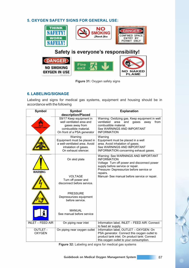
87Guidebook on Medical Oxygen Management System
5. OXYGEN SAFETY SIGNS FOR GENERAL USE:
Figure 31: Oxygen safety signs
6. LABELING/SIGNAGE
Labeling and signs for medical gas systems, equipment and housing should be in
accordance with the following
Figure 32: Labeling and signs for medical gas systems
Symbol Symbol description/Placed
Explanation
S9/17 Keep equipment in well ventilated area and
gases away from combustible material.
On front of a PSA generator
Warning: Oxidizing gas. Keep equipment in well ventilated area and gases away from combustible material. See WARNINGS AND IMPORTANT INFORMATION
Warning
Equipment must be placed in a well-ventilated area. Avoid
inhalation of gases.
On exhaust silencer.
Warning
Equipment must be placed in a wellarea. Avoid inhalation of gases.See WARNINGS AND IMPORTANT INFORMATION concerning exhaust gases.
On skid plate
VOLTAGETurn off power and
disconnect before service.
PRESSUREDepressurizes equipment
before service.
MANUAL
See manual before service
Warning: See WARNINGS AND IMPORTANT INFORMATIONVoltage
Turn off power and disconnect power supply before service or repair.Pressure- Depressurize before service or repairs.Manual- See manual before service or repair.
INLET – FEED AIR On piping near inlet
Information label, INLET –
FEED AIR: Connect to feed air supply.
OUTLET -OXYGEN
On piping near oxygen outlet Information label, OUTLET – OXYGEN: On PSA generator. Connect this oxygen outlet to product tank inlet. On product tank: Connect this oxygen outlet to your consumption.

88 Guidebook on Medical Oxygen Management System
1. BRIEF INTRODUCTION
Medical oxygen is an essential medicine in the treatment of COVID-19 and other serious
respiratory disorders among adults and children in a health facility. Regular and periodic
facility-based audits by dedicated oxygen audit team is needed to ensure rational use of
oxygen, streamline the oxygen supply from different sources of oxygen and ensure safety
measures in oxygen delivery system at facility level. Regular audits, review of audit reports
by the hospital authority and immediate follow up actions can ensure the medical oxygen
supply service is smooth and hassle free.
During this unprecedented time of COVID-19 outbreak, it is often observed that many
health facilities and in turn the districts are consuming oxygen more than the normative as
mandated by clinical recommendations. There may be the case of wastage, leakage and
lack of awareness on appropriate delivery system of medical oxygen among hospital
staffs. Implementing a regular oxygen audit mechanism with constitution of audit teams at
facility and district level could find the exact gap in medical oxygen delivery system and
help the State in saving each CuM of life saving oxygen.
India and especially Maharashtra State had witnessed sudden surge of COVID-19 cases
in almost all districts during second wave. This increase in number of patients led to
increase in demand of oxygen, so being a scarce resource, it is very crucial to use oxygen
judiciously. Therefore, guidelines for rational use of oxygen are being circulated to all the
districts in the State. It is expected to implement these guidelines strictly in Govt and
Private Health Facilities classified as DCH, DCHC and CCC (with oxygen beds).
2. INSTITUTIONAL MECHANISM FOR OXYGEN AUDIT
A. State level Oxygen monitoring Committee/ cell
At State level, one Medical Oxygen Monitoring Committee (MOMC) is to be constituted for
regular review of medical oxygen supply system. Accordingly, MOMC should take all
necessary measures to strengthen the health system of the State which is capable of
delivering medical oxygen at bed side as per clinical need while ensuring all required
safety measures. MOMC is to be constituted by taking State oxygen nodal officer, State
bio medical engineer, State medical equipment procurement managers, respiratory
medicine/anaesthesia specialists, M&E specialists and heads of bio-medical research/
laboratory along with other appropriate administrative heads as members.
The MOMC should collect inputs from all districts and conduct weekly review of medical
oxygen supply system in the state during the surge in COVID-19 case and monthly as a
routine practice. The review should include
Ÿ Status of oxygen sources, storage capacity and availability at secondary and tertiary
care facilities in various districts.
Ÿ District wise availability of oxygen suppliers/refillers and storage capacity.
Ÿ Reviewing the system for regular maintenance of oxygen sources such as PSA, LMO
and oxygen concentrators, storage and maintenance of oxygen cylinders.
GUIDELINES ON FACILITYBASED OXYGEN AUDIT
C H A P T E R 1 0

89Guidebook on Medical Oxygen Management System
Ÿ Status of staff training on medical oxygen delivery procedures.
Ÿ Training status of clinical staff on rational use of oxygen as per clinical need
assessment of patients etc.
Ÿ Reviewing the status of oxygen audit across the districts.
Accordingly, all districts should be provided feedback and be supported for strengthening
the district medical oxygen supply system. MOMC should also develop a repository of
suppliers of oxygen equipments (PSA, LMO, OC, Cylinder, oxy flowmeter etc) for smooth
procurement of these products as per need. Along with this a list of resource persons
available for staff training may be maintained.
B. District level oxygen audit committees
District quality team members may constitute the district level oxygen audit team. At least
one specialist doctor in respiratory medicine is to be nominated as the team member.
Role of district level oxygen audit committee:
a. Conduct a baseline and then periodic (preferably weekly during the surge in cases and
then monthly) assessment of the oxygen supply system in health facilities of the district.
b. Accordingly, a need gap analysis is to be prepared for further sharing with the State
MOMC.
c. Trend analysis of medical oxygen requirement and forecasting the need of the district
would be helpful for appropriate planning of oxygen supply system in the district.
d. Ensure that each health facility of the district with medical oxygen service has
constituted a facility level oxygen audit committee.
e. Ensure that the state approved oxygen audit checklist formats are available in relevant
health facilities.
f. Provide initial orientation to facility level oxygen audit teams on their role,
responsibilities, and appropriate use of state approved oxygen audit checklist formats.
g. Collect, review, and provide immediate feedback to health facilities as per the facility
level oxygen audit reports received from the districts.
C. Hospital/Facility Oxygen audit committee
Hospital oxygen audit team is a facility level team ideally constituting of at least one
respiratory medicine specialist/anesthetist or physician, staff nurse in-charge, pharmacist
and attendants Group D employees. The audit team will also include the additional
medical superintendent and heads of the anesthesia and respiratory medicine wings or
head of the internal medicine wing in case there is no separate respiratory medicine wing
along with the nursing superintendent. The audit committee members have to be identified
and a facility level audit committee needs to be constituted by office order from the hospital
superintendent.
This team is crucial in strengthening the in-house capacity for medical oxygen delivery
system at hospital level. The team members have an important role to play in safe delivery
and rational use of oxygen in their health facility. The oxygen audit committee members
need to be oriented by district oxygen audit team on various elements of oxygen audit and
importance of regular audit on appropriate usage of medical oxygen in the health facility.

90 Guidebook on Medical Oxygen Management System
This team will also serve as facility level mentoring team for clinical staff and attendants on
appropriate handling of medical oxygen related equipments along with ensuring rational
use of oxygen.
Role of facility level oxygen audit committee
Ÿ Supervise inventory planning and record oxygen consumption pattern (Maintain a
record of daily stock of oxygen in hospitals, its use, and leftover stock).
Ÿ The audit committee will register details about the availability and use of oxygen in a
hospital and report to the district oxygen nodal person on a daily basis.
Ÿ Ensure regular repair and maintenance of oxygen sources e.g., PSA plants, LMO tanks
and gas pipelines along with wall mounted gas outlets.
Ÿ Support setting up of oxygen monitoring team in all shifts in hospitals as part of the
committee. It should include a nurse and an operation theatre technician.
Ÿ Oxygen monitoring team should regularly monitor the places where oxygen is given to
patients and inspect the gas pipeline, gas cylinders, wall mounted gas outlets and gas
cylinders to detect and promptly address leakages, if any. Nurse in the team will check
the oxygen mask on regular basis and ensure closure of valves during “no-use” at all
times.
Ÿ The committee will be responsible for regular training to staff nurses, nursing
attendants, ICU/OT technicians on appropriate procedures of oxygen administration,
patient monitoring, oxygen weaning protocols, to detect leaks in oxygen supply
systems and to follow oxygen prescription as directed by the treating physician.
Sensitize nurses and technicians for conservation of oxygen.
3. PERIODICITY OF AUDITS AND REPORT SUBMISSION
Health facility level oxygen audit reports should be submitted on weekly basis to the district
level oxygen nodal officer for review and feedback. The facility based oxygen audit report
should be submitted in a structured checklist format which is approved by State health
department. The weekly audit reports should include the number of leakages identified in
oxygen supply systems, any breakdown of oxygen sources, proportion of admitted
patients on HFNC, non-invasive ventilation, invasive ventilation, nasal cannula, simple
face mask, NRBM etc., utilization of oxygen Vs clinical load of the facility, staff knowledge
and skills related to oxygen equipment use etc.
District oxygen audit committee shall send a monthly report to MOMC with regard to
details of audit conducted. The audit report should include facility wise details of key audit
findings along with immediate action taken to ensure compliance to recommended
practices. The audit report may also accompany a gap analysis of oxygen supply system
and highlight any support requirement from State Health Department.

91Guidebook on Medical Oxygen Management System
4. IMPORTANT FOCUS AREAS RELATED TO OXYGEN AUDIT
Various focus areas of oxygen audit are as follows:
Ÿ Oxygen prescription – Written like any other drug, mention flow rate, end points in terms of
SpO2/ PaO2.
Ÿ Triaging of patients as per their oxygen status should be done at regular intervals.
De-escalate Oxygen therapy is needed as patient improves clinically. If SPO2 is more than
94% for 12 Hrs continuously, then patient should be switched over to intermittent oxygen
therapy.
Ÿ If oxygen cylinders are in use, then it is important to see that the oxygen in the container is up
to an appropriate level and timely changing of empty cylinders is done. This is essential to
prevent sinking of the patients due to want of oxygen at proper pressure and percentage.
Ÿ HFNC use should be minimized. HFNC use at high flow rates should be minimized. When
required, BIPAP should be preferred over HFNC. HFNC should be used only in ICU setting
under supervision of respiratory physician/ physician. HFNC should be used at flow rate more
than 30 l/min only after getting approval from senior most respiratory physician/ physician/
institutional critical care team. Staff should encourage patients to keep mouth closed during
HFNC use.
Ÿ Awake repositioning protocol to be started in all hospitalized patients with hypoxemia. Prone
positioning should be intermittently done in patients with COVID-19 / severe hypoxemia
along with adjunctive physiotherapy to optimize respiratory status. If awake proning protocol
is not followed, reason for the same has to be documented in the case sheet.
Ÿ Wastage of oxygen through leaks should be detected on daily basis and rectified at the
earliest.
Ÿ Ensure closure of valves in pipeline system in “no-use” areas.
Ÿ Maintain base flow in ventilator to minimum if it can be adjusted.
Ÿ Use non-rebreathing bag with optimally fitting mask (Monitor for air hunger-if so, increase
flow rate).
Ÿ Use CPAP machine/BiPAP machine with lower oxygen flow (higher mean airway pressure
can increase oxygenation) instead of high flow oxygen devices.
Ÿ Ensure adequate fit of right size mask (use templates while selecting interface) in patients
receiving non-invasive ventilation to avoid leakage.
Ÿ Ensure right size of endo-tracheal tube with optimal cuff pressure so as to minimise leaks.
OXYGEN SHOULD NOT BE ADMINISTERED WITHOUT PRESCRIPTION
Goals:
Ÿ SpO2›: 90-94% (COPD: 88-90%), if breathing work does not increase.
Ÿ PaO2: 60-70mmHg, (COPD: 55-65mmHg)
Ÿ Monitor SpO2 continuously and make necessary changes so as to meet the
Oxygenation goals.
IN THE CASE SHEET FLOW RATE AND TARGET SPO2 HAS TO BE CLEARLY MENTIONED

92 Guidebook on Medical Oxygen Management System
Ÿ Switch to standby mode when disconnecting the ventilator from patient as required
during feeding. (supplement oxygen with nasal prongs/cannula while feeding as
needed may be used).
Ÿ Use closed suction device thus preventing de-recruitment during open suctioning.
5 REASONS FOR OXYGEN LOSS
Oxygen is an important resource, any wastage or leakage needs to be prevented. Below
are the major reasons for oxygen loss.
Ÿ Inadequate manpower to handle oxygen management system.
Ÿ Improper maintenance of dura cylinders.
Ÿ Leaks in jumbo cylinders.
Ÿ Avoid HFNO (High Flow Nasal Oxygen).
Issue Causes Solutions
Less manpower: Hospital staff
consist of doctors, nurses and
ward boys. Lack of manpower
can lead to -
Ÿ Patients would help
themselves
Ÿ NPM (None per mouth)
settings would not be changed
Ÿ Increase hospital manpower
Ÿ Ensure staff is well trained
Maintenance of dura cylinders:
Dura cylinders store cryogenic
oxygen at - 183 degrees C or
lower. Leaks from dura
cylinders are caused due to
Ÿ Stored for long periods of time
Ÿ Oxygen converts from liquid to
gaseous form and releases in
to the air
Ÿ Rotate dura cylinders
Ÿ Increase pressure of dura
cylinder more than the oxygen
pressure
Leaks from jumbo cylinders:
These are caused due to the
following factors:
Ÿ Faulty valves
Ÿ Handle is not tight
Ÿ Washer is not properly placed
Ÿ Rotate jumbo cylinders
Ÿ Stick tags mentioning last
filling date
Ÿ Keep checking pressure
gauges
Ÿ Use good quality spanners
during maintenance
Ÿ Avoid hammering oxygen
cylinder valves
Avoid HFNO – High-Flow
Nasal Oxygen
Ÿ Make patients lungs lazy
Ÿ Uses more oxygen
Ÿ Replace with NIV (Non Invasive
Ventilation) or BiPAP (Bi level
Positive Airway Pressure)
Ÿ Better health effect on patients
health
5.1 Issues, causes and solutions for preventing oxygen loss
Table 25: Oxygen management system issues, causes and solutions

93Guidebook on Medical Oxygen Management System
5.2 Additional Tips
Ÿ Ensure a knowledgeable bio medical engineer is recruited for installation and
maintenance of the oxygen storage devices.
Ÿ The hospital will have to conduct regular maintenance checks on oxygen storage
devices to ensure there are no leaks.
Ÿ Substandard pressure releasing valves could cause damage to the surrounding.
Ensure proper PRVs are fitted.
Ÿ The right kind of valves need to be fitted on oxygen cylinders .
Ÿ Use fire retardant material for shade for dura (Bison /heat resistant sheets below tin
shade).
Ÿ There should not be any bends or cracks in pipes that are supplying oxygen from the
facility to the hospital or when administering oxygen to the patient.
Ÿ Use good quality spanners. Do not hammer the oxygen cylinders.

94 Guidebook on Medical Oxygen Management System

95Guidebook on Medical Oxygen Management System114 Guidebook on Medical Oxygen Management System
Annexure

97Guidebook on Medical Oxygen Management System96 Guidebook on Medical Oxygen Management System
Liquid medical oxygen tank (VIE) and allied equipment application:
Ÿ Storage of liquid oxygen and supply of high purity oxygen gas for medical use after conversion of liquid to gas through ambient atmospheric vaporizer.
Ÿ The system to be supplied as per relevant applicable standard and certification.
1
ANNEXURE 1: TECHNICAL SPECIFICATIONS OF VARIOUS OXYGEN
SYSTEMS
Annexure Table 1: Technical specifications of Liquid medical oxygen
Sr. No. Liquid Medical Oxygen Plant
Liquid medical oxygen supply
system
Particulars
Ÿ The double walled vacuum insulated evaporator shall be constructed of stainless-steel inner vessel contained within a carbon steel outer vessel. The annular space between the vessels shall be filled with non-inflammable perlite insulation material to insulate under vacuum.
Ÿ The VIE should be self-pressurizing type by partial evaporation of liquid oxygen through a pressure building coil by a non-ferrous imported pressure regulator. The vessel shall be supplied as a functional whole with all materials of construction & the cleaning regime suitable for medical grade liquid oxygen.
2
Liquid medical oxygen storage
tank (VIE)
Ÿ Quantity: 10 KL X 1 No.
Ÿ Installation: Outdoor
Ÿ Type: Double walled, vertical
Ÿ Capacity: Minimum 10,000 litres water capacity- 2 No
Ÿ Design code: ASME Sec. VIII Div. I latest edition / EN - 13458-2
Ÿ Annexure-C/ AD2000 MARKBLATTER 2004 Edition
Ÿ Max. working pressure: 17 Bar G
Ÿ Design temperature: –196ºC to +50ºC
Ÿ Hydraulic Test Pressure: 26 bar G
Ÿ Type of Insulation: Vacuum, Perlite filled
Ÿ Safety Valve Set pressure: 17 Bar G (dual safety valve with three-way diverter valve)
Ÿ Bursting Disc Set Pressure: 23 Bar G (Bursting disc)
Ÿ Standard fittings: Pressure rising coil, pressure building regulator of adequate capacity and size, dual safety valve with imported three-way diverter valve, bursting disc., pressure gauges, liquid over-flow line, Liquid level gauge and adequate numbers of extended spindle glove valve etc.
Ÿ Maximum evaporation rate: <0.35% of net value.
Ÿ Material of construction: Inner shell and wetted parts of SS 304 outer shell of CS ASTMA 516 Gr. 70 / CGA 341 2002 EN13455 S275/S355
Ÿ Joint efficiency: 100%
Ÿ Radiography: 100% for inner, for outer spot
Ÿ External piping: From LMO tank to vaporizer SS304
Ÿ From vaporizer to inlet of pressure reducing station SS304
Ÿ From outlet of pressure reducing station to main header copper
Ÿ Cryogenic valves: Non-ferrous (Imported)
Ÿ Cryogenic safety valves: Imported
Ÿ Pressure building regulator: Non-ferrous.
Ÿ Leak detection test: Helium leak detection
Ÿ Painting: Primer and finish with white RAL 9010
Ÿ Inspection: By 3rd party (SGS/LLOYDS/TUV)
Ÿ Cleaning: Degreasing for oxygen service and pressurize with nitrogen.
Ÿ Withdrawal rate: 1000 cum per hr. at 12 Bar G
3
Liquid oxygen tank with required
accessories

99Guidebook on Medical Oxygen Management System98 Guidebook on Medical Oxygen Management System
Ÿ LMO tank along with P&ID shall be fitted with the following accessories: Top fill valve, bottom fill valve, liquid charging line blow valve, liquid delivery valve, overflow valve, gas blow valve, filling coupling, vaporizer coupling, liquid level gauge ( Dial 100 mm), high level valve, equalizing valve, low level valve, pressure gauge (100mm dial, Range 0-25 kg/cm2), pressure gauge isolation valve, pressurizing valve, pressurizing coil, filter, pressure regulator, economizer, check valve, evacuation port, vacuum gauge connection port/ vacuum probe valve.
4 Accessories
Ÿ Two safety valves for inner vessel fitted on pipeline with flow divert valve.
Ÿ Rupture disc for inner vessel
Ÿ Safety valve for inlet pipeline
Ÿ Safety valve for pipeline of pressurizing evaporator
Ÿ One rupture disc/ safety device on outer vessel.
5 Safety Fittings
The liquid medical oxygen tank shall accompany the original quality test certificate covering following documents:
Ÿ Approval letter from CCOE along with approved drawing from CCOE.
Ÿ Approval letter from CCOE for use of cryogenic vessel(s) at site.
Ÿ Certificate from the authorized inspection agency
Ÿ Heat chart for pressure parts
Ÿ Dimension checks report
Ÿ Dished end reports
Ÿ Mechanical properties test report for production test coupon.
Ÿ Visual inspection report.
Ÿ Radiography examination report.
Ÿ Liquid penetrant examination
Ÿ Cleaning inspection report
Ÿ Hydro-pressure test report.
6 Sub mittals
Ÿ Two vessel of 1X10 KL liquid oxygen VIE vessel system will be the primary (main) supply source.
Ÿ In case of failure in liquid oxygen supply, it should automatically switch over to an emergency oxygen manifold having 2 X 10 cylinders.
Ÿ Design should be state-of-the-art.
Ÿ The unit should consist of a double walled vertical vessel (inner pressure vessel made of stainless steel and outer vessel of carbon steel).
Ÿ It should be fitted with standard accessories and should be “passed” the standard inspection requirement at factory for VIE.
Ÿ The copy of the certificate should be forwarded to HLL prior to shipping and original should be enclosed along with the shipping document.
Ÿ Bidder should follow International Standards
7Liquid medical oxygen supply
system
Ÿ Capacity of liquid oxygen storage tank: 10 KL
Ÿ Gas outlet pressure to be maintained at 4.2 kg/cm2.
Ÿ Space taken for installation should be as per regulations of Indian explosive controller and having easy access for LMO tank.
Ÿ The site would be protected by fence around, well it by sodium vapour lamps and demarcated with proper signage.
Ÿ Indication of liquid oxygen level and outlet gas pressure should be provided.
8
Product and service
specification
Automatic change over should be provided between the LMO tank and existing oxygen manifold.
(Existing manifold is of 2 x 10 cylinders)9
LMO tank and existing oxygen
manifold
Sr. No. Liquid Medical Oxygen PlantParticulars
Ÿ Product: The liquid medical oxygen (LMO) supplied at site should be of IP grade. The LMO supplied should comply with all relevant SMPV regulations and standards under per view of the Indian Drugs and Cosmetic Act rules. They should also satisfy the IP 2007 specifications.
Ÿ Storage tank specifications: The storage tank and the vaporizer coils should be designed as per the ASME Sec. VIII Div. I latest Edition / EN -13458-2 Annexure-C/ AD2000, MARKBLATTER 2004 Edition
Ÿ The cryogenic vessel will be of cylindrical shape with vaporizer and the pressure control system. It should be provided with the essential components to fill the liquid, to build up pressure, to relieve pressure, to withdraw product and to evacuate the vessel. All protective, safety and alarm provisions mandatory to liquid medical oxygen plants should be supplied.
10Specification of
components
Configuration: Vertical
Ÿ Inner vessel maximum allowable working pressure: 17 kg/cm2
Ÿ Inner vessel hydrostatic test pressure: Greater than 26 kg/ cm2
Ÿ Outer vessel material of construction: Carbon steel
Ÿ Inner vessel material of construction: Stainless steel
Ÿ Independent AV coil should be provided with each vessel
11
The requirement of the cryogenic
vessel
Ÿ Vacuum insulated evaporator vessel should have a capacity of 1X10 kilo litres. The AV coil should have adequate capacity to handle the gas flow requirements of the hospital.
Ÿ Vaporizer coil
Ÿ Maximum operating Pressure: 20 kg/cm2
Ÿ Design Pressure: 22 kg/cm2
Ÿ Pneumatic test pressure: Greater than 24 kg/cm2
Ÿ Inlet temperature: - 196 to +40°C.
Ÿ Duty cycle: Continuous duty
Ÿ Flow rate: 1200 cubic meter/ hour
Ÿ The fence, foundation, lighting, signage, approach gate, approach road etc. are to be designed and installed by the vendor.
12Storage tank
capacity
The vendor should ensure that all international safety norms and standards applicable as implemented and certified by the CCE.
Following are the mandatory provisions for vessel:
Ÿ Vessel low liquid level alarm
Ÿ Vessel low pressure alarm
Ÿ Pipeline low pressure alarm.
Ÿ Twin regulator
Ÿ Twin safety valve
Ÿ Non return valve and 3-way diverter (bypass) valve
Ÿ Automatic changeover to manifolds with control panel.
Ÿ Alarm on indicating manifold in use in case the vessel is not in use.
Ÿ Alarm on low pressure back-up manifold cylinders
13 Safety
All statutory requirements of the Chief Controller of Explosives of India and SMPV rules need to be followed; besides all regulations and guidelines put forward by the Govt. of India from time to time should be followed.
14Statutory
requirements
Ÿ All routine preventive maintenance and break-down maintenance of the liquid oxygen plant should be done by the vendor. Experienced personnel should be readily available.
Ÿ Log of all works undertaken in the plant should be meticulously maintained by the vendor.
Ÿ Bulk cylinders for the manifold will be arranged by the hospital. The hospital will ensure that the cylinders are full and ready to use during emergencies.
15 Maintenance
Ÿ Satisfactory Training to be provided at site to the designated authorities for minimum 2 weeks16 Training
Source - Technical Specifications- Liquid Medical Oxygen Plant
[Covid Medicine Building, Government Medical College & Hospital, Aurangabad]
Sr. No. Liquid Medical Oxygen PlantParticulars

101Guidebook on Medical Oxygen Management System100 Guidebook on Medical Oxygen Management System
Annexure Table 2: Technical specifications for procurement- oxygen cylinders
General technicalrequirements
Oxygen and medical air cylinders are refillable containers for such gas, in a compressed form, available in international standard capacity/pressure and dimensions.
The cylinders can be made of steel, aluminium/alloy, carbon fiber or other composite material.
Nominal pressure should be 13 700 kPa (137 bar, 1987 psi) for standard cylinders and 23 000 or 30 000 kPa (230 or 300 bar, 3336 or 4351 psi) for cylinders fitted with integral valves.
Each cylinder is fitted and supplied with a valve.
Multiple options for pressure regulators, various fitting and outlets, and integral valves should be available separately.
Specific ISO, American National Standards Institute (ANSI) and other international colour coding for oxygen and medical air should be available.
Accessories like holders, racks and trolleys should be available separately.
Oxygen cylinders:
Ÿ Refillable cylinders for compressed oxygen (oil-free and compliant to ISO standards) or air (compliant to ISO standards) for medical use.
Ÿ Fitted with a primary valve, standard (pin index or bullnose) or integral, refillable.
Ÿ Nominal pressure 13 700 kPa (137 bar, 1987 psi), for standard valve cylinders, or 23 000–30 000 kPa (230–300 bar, 3336–4351 psi) depending on the cylinder model, for integral valve cylinders.
Ÿ Compressed Gas Association (CGA) approved seamless steel/aluminium alloy/composite body, colour coding according to ISO/ANSI/CGA/NFPA, sizes ISO/US standard.
Ÿ Cylinders supplied with optional pressure regulators, multiple fitting according to all the international standards.
Ÿ Safety over-pressure release valve (if not built-in in the integral valve fitted cylinders).
Primary valve and pressure regulator assemblies:
Ÿ Pin index or bullnose primary valve and compatible pressure regulators, providing pressure regulated supply of oxygen (oil-free and compliant to ISO standards) or medical air (compliant to ISO standards).
Ÿ Steel/plated brass/aluminium casing, brass valve.
Ÿ Nominal inlet pressure 13 700 kPa (137 bar, 1987 psi), maximum 20 000 kPa (200 bar, 2901 psi).
Ÿ Outlet pressure 345 kPa (3.5 bar, 50 psi).
Ÿ Integrated manometer, 0–20 000 kPa (0–200 bar, 0–2901 psi).
Ÿ Safety over-pressure release valve.
Ÿ Pressure regulator supplied with flowmeter, if required – see configurations/options for specifications.
Integral valves:
Ÿ All-in-one cylinder valve for oxygen (oil-free and compliant to ISO standards) or medical air (compliant to ISO standards), providing direct attachment to the cylinder, pressure regulation and supply of medical gas with adjustable flow rate.
Ÿ Steel/plated brass/aluminium casing, brass valve.
Ÿ 6 mm barbed and BS 5682 Schrader (if applicable depending on the size of the cylinder) outlets.
Ÿ Integrated open/close valve, outlet nominal pressure 400 kPa (4 bar, 58 psi).
Ÿ Inlet pressure 23 000–30 000 kPa (230–300 bar, 3336–4351 psi), depending on the cylinder model.
Ÿ Integrated refill valve ISO 5145/CGA 540 compliant.
Ÿ Integrated manometer, covering the full nominal pressure range of the cylinder, standard 23 000– 30 000 kPa (230–300 bar, 3336–4351 psi), for integral valve cylinders, or whatever applicable.
Ÿ Integrated flowmeter.
Ÿ Safety over-pressure release valve.
Capable of being stored in ambient temperature of at least 5–50 °C, relative humidity of at least 15–95% non-condensing.
1
Suitable for continuous operation in ambient temperature of at least 5–45 °C, relative humidity of at least 15–90% non-condensing.
Specific requirements for altitude may be required, depending on the installation site.
Applicable regulations on transport and storage of cylinders may vary if the cylinders are empty or partially/fully filled.
Compliance with regulations on hazardous goods, flammable, explosive, compressed gas, according to the Globally Harmonized System of Classification and Labelling of Chemicals (GHS) and international standards, is mandatory.
1
2 Configurations / options
Oxygen cylinder configurations/versions/options:
Standard and MRI-compatible versions.
Specific ISO/ANSI/CGA/NFPA colour coding for oxygen and medical air.
Seamless cylinders made of steel, aluminium/alloy, carbon fibre or other composite material (CGA approved and compliant to ISO applicable standards).
Pin index/bullnose and integral valve options.
OXYGEN and MEDICAL AIR cylinders with STANDARD VALVE available in all the ISO international standard sizes, including size AZ, C, D, E, F, G, H, J, and also US sizes M2 to M 265 (not all sizes apply to both oxygen and medical air).
The type of standard valve has to be compliant to international ISO and US standards, i.e. pin index ISO 407/BS 850/CGA 870 valve, CGA 540 valve, 5/8 inch BSP (F) Bullnose BS 341 valve, also according to the size/pressure of the cylinder and to any applicable regulation.OXYGEN cylinders should be available also with INTEGRAL VALVE (with manometer and flow regulator, 400 kPa (4 bar) nominal outlet pressure, 6 mm barbed and BS 5682 Schrader outlets), in all the ISO international standard sizes, including size ZA, CD, ZD, HX and ZX, and also US sizes in M coding system.
Regulator/integral valve configurations/versions:
Standard and MRI-compatible versions.
Oxygen and medical air versions.
Pressure regulators and integral valves should be available with DISS and 6 mm barbed outlet.
Pressure regulators should be available in basic open/close model and fitted with integrated flowmeter, Thorpe tube or Bourdon gauge.Pressure regulators and integral valves with Thorpe or Bourdon flowmeter should be available at least in the following flow ranges, for oxygen and medical air:
Ÿ Low flow 0–3 or 4 L/min (only for oxygen), discrete (dial) flow setting (indicative steps 0, 0.03, 0.06, 0.12, 0.25, 0.50, 0.75, 1.0, 1.5, 2.0, 3.0, 4.0), accuracy 10%.
Ÿ Standard flow 0–15 L/min, discrete (dial) flow setting (indicative steps 0, 0.25, 0.5, 1.0, 2.0, 3.0, 4.0, 5.0, 6.0, 8.0, 10.0, 12.0, 15.0), accuracy 10%.
Ÿ High flow 0–25 L/min minimum, discrete (dial) flow setting (indicative steps 0, 0.25, 0.50, 1.0, 2.0, 3.0, 4.0, 6.0, 8.0, 10.0, 15.0, 25.0), accuracy 10%. Pressure regulators and integral valves with Thorpe or Bourdon flowmeter should be available at least in the following flow ranges, for oxygen and medical air:
Ÿ Low flow 0–3 or 4 L/min (only for oxygen), accuracy 10%, indicative graduation (L/min) 0.03, 0.06, 0.12, 0.25, 0.5, 0.75, 1.0, 1.5, 2.0, 3.0, 4.0.
Ÿ Standard flow 0–7 or 8 and 0–15 or 16 L/min, accuracy 10%, graduation 0.5 L/min (0.5–3 range) and 1 L/min (3–max range).
Ÿ High flow 0–25 L/min minimum, accuracy 10%, graduation 0.5 L/min first increment and 1 L/min full range.
Cylinder body, primary valve and pressure regulator or integral valve assembly, outlet connectors, safety pressure release valve, valve/regulator knob, manometer and flowmeter (for integral valve).Portable or stationary (depending on the size of the cylinder).Brass valve assemblies. Cylinders made of steel, aluminium/alloy, carbon fibre or compound material.
Bronze/brass/synthetic sealings. All materials in contact with air certified for medical use.

103Guidebook on Medical Oxygen Management System102 Guidebook on Medical Oxygen Management System
Suitable for continuous operation in ambient temperature of at least 5–45 °C, relative humidity of at least 15–90% non-condensing.
Specific requirements for altitude may be required, depending on the installation site.
Applicable regulations on transport and storage of cylinders may vary if the cylinders are empty or partially/fully filled.
Compliance with regulations on hazardous goods, flammable, explosive, compressed gas, according to the Globally Harmonized System of Classification and Labelling of Chemicals (GHS) and international standards, is mandatory.
3 Displayed parameters Pressure and flow (for integral valve cylinders only).
4 User adjustable settings Open/close control, pressure and flow (for integral valve cylinders
only).
5 Accessories
Cylinder holding, carts, trolleys. Supplied with keys and tools to operate
valves and regulators. Complete set of tubing and adapters to use the
pressure regulator and the integral valve with all common international
standard fittings, for medical gas sources, patient circuits and other
medical devices.
6 Spare parts
Common and frequently used spare parts, sensors/ transducers/
actuators, reusable probes/cables/patient connection accessories,
periodic maintenance and calibration kits/materials, renewables that
should be procured together with the equipment and in quantity
sufficient for 2 years recommended (1 year at least) of typical use.
These items should be supplied to each department where the
equipment is installed and also to central and local maintenance
department. Sealing set, maintenance kit, regulating unit (knob),
adapters and connectors, keys and tools to operate the valves. Items in
the above-mentioned categories that are not frequently needed or
require specialized skills to be used/replaced. The need and the
quantity of these items should be assessed by technical staff before
procuring the main medical devices, and procured together. It is
recommended to store and use them in central and local maintenance
department.Primary valve assembly, regulator valve assembly,
pressure safety valve, inlet/outlet connectors, full set of sealings,
integral valve assembly, manometer and flowmeter (for integral valves).
7Mobility, portability
(if relevant)Portable or stationary (depending on the size of the cylinder).
8Documentation requirements(English language mandatory)
Set: user and maintenance manuals, hard and soft copies,
in English (mandatory) and other languages (preferable). Certificate of
calibration and inspection. Troubleshooting, calibration and routine
maintenance. List of all spare parts and accessories, with part numbers
and contact details for parts supply. Document with contact details of
manufacturer, supplier and local service agent.
9Transportation and
storage and primarypackaging labelling
Applicable regulations on transport and storage of cylinders may vary if
the cylinders are empty or partially/fully filled.
Compliant with regulations on hazardous goods, flammable,
explosive, compressed gas, according with GHS and international
standards is mandatory.
Sealed container.
Capable of being transported and stored in ambient temperature of at
least 5–50 °C, relative humidity of at least 15–95% non-condensing.
Specific requirements for altitude may be required, depending on the
installation site.
Hazardous goods, flammable, explosive, compressed gas labelling
according with GHS and international standards and regulations.
Primary packaging:
Unit of use: one (1) cylinder or valve/regulator in a box or case with
manufacturer's instruction for use, spare parts and accessories (when
applicable). Cylinder type and content in litres, tare weight (weight
when empty), maximum cylinder pressure, cylinder size code.
Labelling on the primary packaging:
Name and/or trademark of the manufacturer; manufacturer's product
reference; type of product and main characteristics; lot number
prefixed by the word “LOT” (or equivalent harmonized symbol) (if
applicable); information for particular storage conditions (temperature,
pressure, light, humidity, etc.), as appropriate (or equivalent
harmonized symbol); information for handling, if applicable (or
equivalent harmonized symbol).
Over packaging:
Packaging unit.
Labelling on the packaging unit:
Labelling to be the same as primary packaging. Extra information
required: number of units.
10Standards, for the
manufacturer
Certified quality management system for medical devices (e.g. ISO
13485). General quality management (e.g. ISO 9001). Application of
risk management to medical devices (e.g. ISO 14971).
11Regulatory approval/
certification
Free sales certificate (FSC) or certificate for exportation of medical
device provided by the authority in manufacturing country.
Proof of regulatory compliance, as appropriate, per the product's risk
classification (e.g. Food and Drug Administration [FDA] and/or
Conformité Européenne [CE]).
12Standards, for product
performance
Compliance to the following international standards or to regional or
national equivalent (including the technical tests for safety and
performance from accredited laboratory or third party) for:
Colour coding ISO or ANSI for medical gases.
Conforms to ISO, NFPA and/or CGA standards, and/or UL or CSA
approved.
ISO 11114 Gas cylinders – Compatibility of cylinder and valve materials
with gas contents.
ISO 10524 Pressure regulators for use with medical gases.
ISO 15002 Flow-metering devices for connection to terminal units of
medical gas pipeline systems.
ISO 15245 Gas cylinders – Parallel threads for connection of valves to
gas cylinders.
ISO 10297 Gas cylinders – Cylinder valves – Specification and type
testing.
ISO 17871 Gas cylinders – Quick-release cylinder valves – Specification
and type testing.
ISO 17879 Gas cylinders – Self-closing cylinder valves – Specification
and type testing.
ISO 407 Small medical gas cylinders – Pin-index yoke-type valve
connections.
ISO 5145 Cylinder valve outlets for gases and gas mixtures – Selection
and dimensioning.
ISO 11117 Gas cylinders – Valve protection caps and valve guards –
Design, construction and tests.
ISO 11363 Gas cylinders – 17E and 25E taper threads for connection of
valves to gas cylinders.
ISO 12209 Gas cylinders – Outlet connections for gas cylinder valves for
compressed breathable air.
ISO 14246 Gas cylinders – Cylinder valves – Manufacturing tests and
examinations.
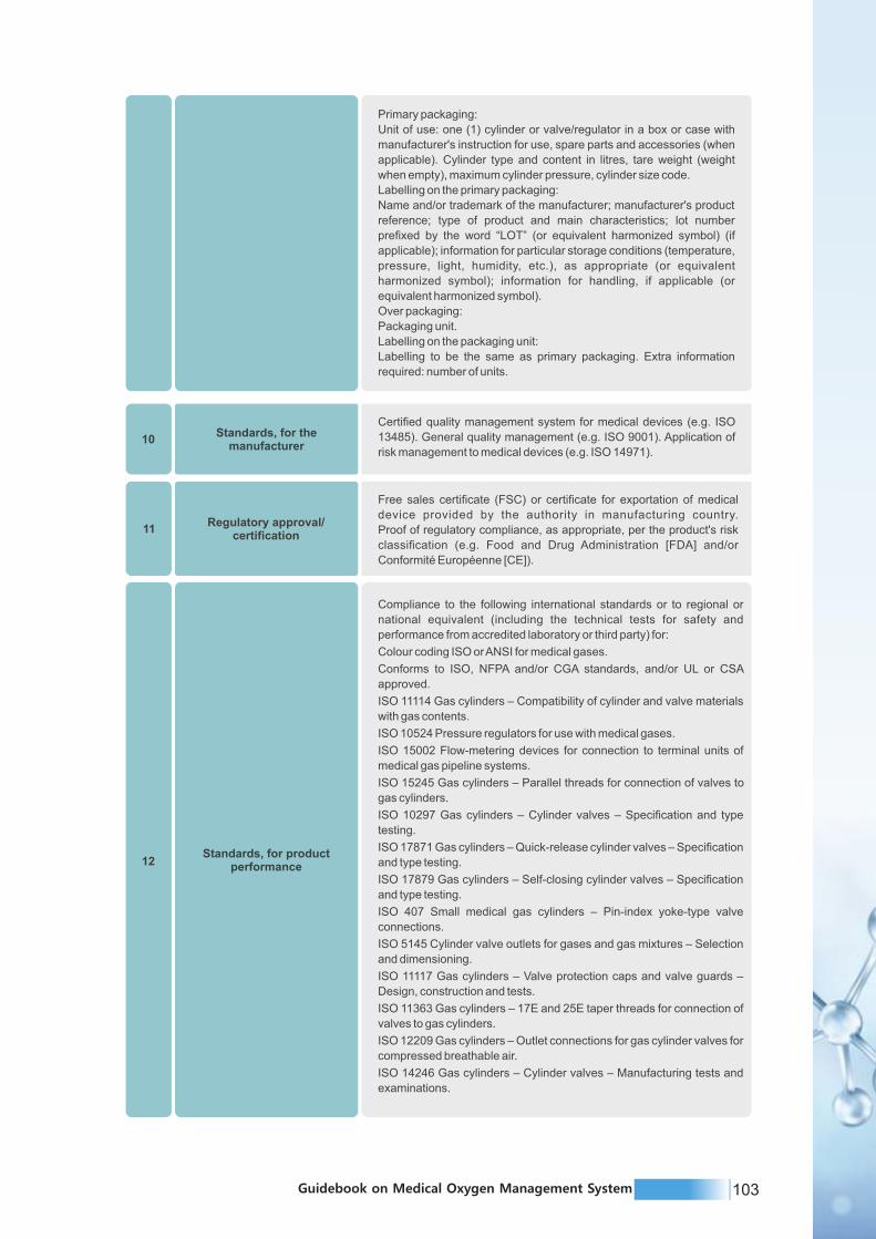
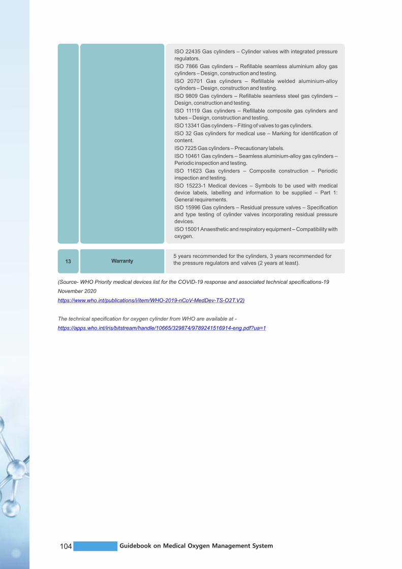
105Guidebook on Medical Oxygen Management System104 Guidebook on Medical Oxygen Management System
ISO 22435 Gas cylinders – Cylinder valves with integrated pressure
regulators.
ISO 7866 Gas cylinders – Refillable seamless aluminium alloy gas
cylinders – Design, construction and testing.
ISO 20701 Gas cylinders – Refillable welded aluminium-alloy
cylinders – Design, construction and testing.
ISO 9809 Gas cylinders – Refillable seamless steel gas cylinders –
Design, construction and testing.
ISO 11119 Gas cylinders – Refillable composite gas cylinders and
tubes – Design, construction and testing.
ISO 13341 Gas cylinders – Fitting of valves to gas cylinders.
ISO 32 Gas cylinders for medical use – Marking for identification of
content.
ISO 7225 Gas cylinders – Precautionary labels.
ISO 10461 Gas cylinders – Seamless aluminium-alloy gas cylinders –
Periodic inspection and testing.
ISO 11623 Gas cylinders – Composite construction – Periodic
inspection and testing.
ISO 15223-1 Medical devices – Symbols to be used with medical
device labels, labelling and information to be supplied – Part 1:
General requirements.
ISO 15996 Gas cylinders – Residual pressure valves – Specification
and type testing of cylinder valves incorporating residual pressure
devices.
ISO 15001 Anaesthetic and respiratory equipment – Compatibility with
oxygen.
5 years recommended for the cylinders, 3 years recommended for
the pressure regulators and valves (2 years at least).13 Warranty
(Source- WHO Priority medical devices list for the COVID-19 response and associated technical specifications-19
November 2020
https://www.who.int/publications/i/item/WHO-2019-nCoV-MedDev-TS-O2T.V2)
The technical specification for oxygen cylinder from WHO are available at -
https://apps.who.int/iris/bitstream/handle/10665/329874/9789241516914-eng.pdf?ua=1
Pipe material
Copper Pipes will be Solid drawn, seamless, de-oxidized, non-arsenical, half hard tempered and degreased, materials conforming to BS: 6017/1981 (Cu-DHP) manufactured as per BS:2871/1971 and dimension tolerances conforming to BS-EN 1057. Pipe fittings conform to BS-EN 1254-3:1998. Lloyd's certified
FittingsEnd-feed type, made from the same grade of copper as the pipes, and in accordance with the requirements of BS- EN 1254-1: 1998 Part 1.
Delivery to site
In degreased condition, plugged or capped at both ends and
supplied sealed in protective polythene bags, accompanied by
certificate from Lloyd's certified
Joints, on siteTo be brazed, except for mechanical joints used for components,
employing a method that permits the joints to maintain their
mechanical characteristics upto 600 degC.
Brazing systemFluxless brazing using a copper-phosphorous brazing alloy to
BS-1845.
Pipe wall thickness Copper pipe OD (in mm) 12,15,22,28 42 Thickness (in mm) 0.9
1.2
Pipe clampsShall be non-reactive to copper and be of non-ferrous or non-
deteriorating plastic suitable for the diameter of the pipe.
Pipeline supports Spacing not to exceed 1.5M, irrespective of the pipe diameter.
Passage through walls & floors Through suitable sleeves.
Earthing To be connected to one or more earth terminals.
PaintingAll exposed pipes to be painted with two coats of synthetic
enamel paint, the color codification complying with ISO 5359 /
IS 2379.
Marking and colour coding
To marked with the name and / or symbol adjacent to shut-off
valves, at the junctions and the changes of direction, before and
after walls and partitions, etc. at the intervals of no more that 10M
and adjacent terminal units.
Direction marksMarking to include arrows denoting direction of flow and letters
used for marking shall not be less than 6mm high.
Identification
All concealed pipes to have gas identification bands/ labels are
at appropriate distance, similarly all pipes which need
embedding in the wall will to be tested/ painted/ labled and
properly insulated in accordance with ISO 5359.
Post-installationAfter erection, the pipelines are to be flushed and purged clean
with dry nitrogen gas.
Testing
Pressure testing using dry nitrogen gas at 1.5 times the working
pressure for atleast 24 hours. System should exhibit its integrity
and no-leakage. All contraindications, if any, to be carefully
examined, problems diagnosed and necessary rectifications/
substitutions carried out, and test repeated after re-purging the
lines.
COPPERPIPES
SERVICE Oxygen
GROUND COLOUR Canary, Yellow
FIRST BAND White
SECOND BAND NA
COLOURCODEFOR
MEDICALGASES
PIPES Asper IS2379-1963
Annexure Table 3: Technical specifications for medical gas pipeline system

107Guidebook on Medical Oxygen Management System106 Guidebook on Medical Oxygen Management System
Type Oxygen
Type of outlet Canary, Yellow
Valves White
Inlet NA
GAS OUTLET POINTS
FOR OXYGEN INDIAN: [Approx. Quantity
in No: Oxygen (147)]
Front plate Colour-coded
Compliance NFPA-99 & EN-737
Post-installation purging After erection, to be flushed and purged clean with dry nitrogen
ServiceAs secondary/ reserve source, the primary source being the liquid oxygen bullets arranged through other contracts.
Top Frame
High pressure copper pipes of size ½ ” I.D. x 15swg, high pressure brass fittings made of high tensile brass, non-return valves & high pressure copper tail pipes, made of high pressure copper pipes of size ¼ ” I.D. x 15swg
Middle & Bottom framesTo suit both round and flat bottom cylinders.
OXYGEN MANIFOLD
SYSTEM
Main manifold configuration 2 x 10 cylinders
Emergency Manifold 2 x 2 cylinders with single regulator
Pressure rating 145 kg/sq.cm.
Flow rate [specify] attach calculation
Format Wall-mounting straight line.
High pressure regulatorsFor both manifold systems for reducing the cylinder pressure suitable to the line pressure.
Source shut-off ValvesFor ease of changing and positioning, without closing the bank.
FilterPore size of not exceeding 100um, between the cylinder(s) andthe first pressure regulators.
FixityCylinder to be set in place using cylinder brackets andfixing chains, all zinc plated.
PaintingAll works to be powder coated, the color codificationcomplying with ISO 5359/ IS 2379.
Specific requirementNon-halogenated polymer materials only are permittedto be used in the non-return valves.
Delivery to site
In degreased condition, plugged or capped at all ends andsupplied sealed in protective polythene bags, accompaniedby pre-delivery test certificate.
TestingPre-delivery and post installation pressure testing to1.5 times the working pressure.
Test documentation
Pre-delivery test certificate to accompany supply to site.Post-installation testing to be witnessed by the Engineer,who shall receive the documents.
Company personnel should visit the site for locating the site of gas bank and for estimate
for calculating length of pipeline & other details.
GE
NE
RA
LIN
ST
RU
CT
ION
S
Demonstration should be arranged by the company for accepting the specification
Per unit cost of each item should be quoted.
The quotation for all the items should be given together and no separate cost of any
nature will be entertained subsequently
Company should have installed the system at 3 institutes in India and should produce
certificate of satisfactory service report from these institutes
The copy of all certificates relevant to materials supplied must be produced along with
the tender and at the time of delivery of the material e.g. Lloyd's certificate for copper pipe
Company who gets the contract must submit the AUTOCAD DRAWING of the system
for final approval of technical committees.
Company should arrange for training of hospital staff and company personnel should
be available till hospital staff is trained.
(Source: https://arogya.maharashtra.gov.in/Site/Uploads/Tenders/db34f3ee-d081-405e-a6c0-
f76388b688c586%20CENTRALIZED%20OXYGEN.pdf)

107Guidebook on Medical Oxygen Management System106 Guidebook on Medical Oxygen Management System
Type Oxygen
Type of outlet Canary, Yellow
Valves White
Inlet NA
GAS OUTLET POINTS
FOR OXYGEN INDIAN: [Approx. Quantity
in No: Oxygen (147)]
Front plate Colour-coded
Compliance NFPA-99 & EN-737
Post-installation purging After erection, to be flushed and purged clean with dry nitrogen
ServiceAs secondary/ reserve source, the primary source being the liquid oxygen bullets arranged through other contracts.
Top Frame
High pressure copper pipes of size ½ ” I.D. x 15swg, high pressure brass fittings made of high tensile brass, non-return valves & high pressure copper tail pipes, made of high pressure copper pipes of size ¼ ” I.D. x 15swg
Middle & Bottom framesTo suit both round and flat bottom cylinders.
OXYGEN MANIFOLD
SYSTEM
Main manifold configuration 2 x 10 cylinders
Emergency Manifold 2 x 2 cylinders with single regulator
Pressure rating 145 kg/sq.cm.
Flow rate [specify] attach calculation
Format Wall-mounting straight line.
High pressure regulatorsFor both manifold systems for reducing the cylinder pressure suitable to the line pressure.
Source shut-off ValvesFor ease of changing and positioning, without closing the bank.
FilterPore size of not exceeding 100um, between the cylinder(s) andthe first pressure regulators.
FixityCylinder to be set in place using cylinder brackets andfixing chains, all zinc plated.
PaintingAll works to be powder coated, the color codificationcomplying with ISO 5359/ IS 2379.
Specific requirementNon-halogenated polymer materials only are permittedto be used in the non-return valves.
Delivery to site
In degreased condition, plugged or capped at all ends andsupplied sealed in protective polythene bags, accompaniedby pre-delivery test certificate.
TestingPre-delivery and post installation pressure testing to1.5 times the working pressure.
Test documentation
Pre-delivery test certificate to accompany supply to site.Post-installation testing to be witnessed by the Engineer,who shall receive the documents.
Company personnel should visit the site for locating the site of gas bank and for estimate
for calculating length of pipeline & other details.
GE
NE
RA
LIN
ST
RU
CT
ION
SDemonstration should be arranged by the company for accepting the specification
Per unit cost of each item should be quoted.
The quotation for all the items should be given together and no separate cost of any
nature will be entertained subsequently
Company should have installed the system at 3 institutes in India and should produce
certificate of satisfactory service report from these institutes
The copy of all certificates relevant to materials supplied must be produced along with
the tender and at the time of delivery of the material e.g. Lloyd's certificate for copper pipe
Company who gets the contract must submit the AUTOCAD DRAWING of the system
for final approval of technical committees.
Company should arrange for training of hospital staff and company personnel should
be available till hospital staff is trained.
(Source: https://arogya.maharashtra.gov.in/Site/Uploads/Tenders/db34f3ee-d081-405e-a6c0-
f76388b688c586%20CENTRALIZED%20OXYGEN.pdf)

109Guidebook on Medical Oxygen Management System108 Guidebook on Medical Oxygen Management System
TECHNICAL SPECIFICATION FOR PSA PLANTS (AS PER GOI TENDER
DOCUMENT)
1. Compressed Air system consisting screw type compressor (2 numbers to be
supplied with each PSA system)
I. The oxygen concentrator should be supplied with Air compressor system to meet the
peak load at atmospheric air and pressure requirement.
II. The compressor should be suitable as per site conditions, for working pressure of 7.5-
8 Bar, fitted with electric motor, three phase, AC 415 ± 1% volts, 50 Hz frequency,
rotary screw element complete with dry paper type suction air filter with silencer,
conveniently located for easy replacement of filter element with integrated regulating
valve for load/ unload control system, simple design with only one moving part, need
no regular adjustment, three way solenoid valve required for load/ unload regulation
of the compressor, air/ oil temperature sensor to sense the air oil temperature,
electronic controlled that optimizes operations of the compressed system, should act
as intelligent user interface for improved navigation, should monitors, controls,
protect the compressed system.
III. Start/ Stop for starting/ stopping the compressor having inbuilt display unit with the
keypad users interface for indicating the following messages.
IV. Operation Type: Automatic loading and unloading of Compressor Control Type:
Local, Remote & Computer Timer Activated / not activated, Discharge Pressure,
running hours, loading hours, regulator hours, service Plan.
V. Compressor Package is enclosed in a powder coated acoustic canopy with sound
absorbing material for limiting the noise level. Canopy is pressurized ensuring no
pressure drop at suction filter and avoids entry for dust particles in the element in the
anti-vibration mounts support electric motor and compressor unit and isolate the
moving components from the rest of the structure. The desired working pressure of
the compressed dry air should be 7.5-8.0bar.
VI. Compressed air system comprising of screw air compressor, air cooled with PLC
based control panel coupled with motor assembly.
VII. The compressor should be capable of delivering air as required for PSA, pressure
swing adsorption generator.
VIII. The compressor shall have to be with all standard accessories compatible with
oxygen generator.
IX. The flow capacity of the compressor and delivery pressure shall be as specified by
Core PSA Medical Oxygen Generator service provider. The motor rating shall be
suitable for air compressor.
X. Average ambient conditions to be considered for air compressor with regards to
temperature and site elevation. The site should be able to work in all weather
conditions.
XI. The air compressor shall be manufactured to internationally acceptable standards
with CE mark and ISO 9001 and ISO 13485 certification.
a. ISO 8573-1: Compressed air – Part 1: Contaminants and purity classes.
b. ISO 8573-2: Compressed air – contaminant measurement – Part 2: Oil aerosol
content.
c. ISO 8573-4: Compressed air – contaminant measurement – Part 4: particle content.
d. ISO 5011: Inlet air cleaning equipment for internal combustion engines and
compressors – performance testing.
XII. Intake air temperature shall be conditioned to between (minus)10 to +55 deg C and ≤95% RH
(or plant operating conditions as indicated by supplier).
XIII. It should be supplied with all accessories for full installation and operation -flywheel,
foundation bolts, motor pulley, v-belts, belt guard, and slide rails for the motor.
XIV. EFF1 (CEMEP) rated totally enclosed fan-cooled, IP55 class F electric motors shall be used
and incorporate maintenance- free greased for life bearings. Motors with lower (equivalent)
efficiency ratings are not acceptable.
2. Refrigerant Air Dryer
I. Refrigerant type Air Dryer should have inlet pressure equal to outlet pressure from Air 0 ocompressor, inlet air temperature less than 45 C, ambient temperature +0 C to
o 0+45 C, dew point temperature of maximum +3 C and inlet air capacity compatible to
air delivery of 7.5-8 Bar pressure.
ii. The dryer shall be provided with power supply as required by dryer vendor.
iii. It should be equipped with safety valves. It should be of simple plug and playconcept.
iv. The pressure shall be self-regulating.
v. The dryer shall include the following components
a) Refrigerant Circuit
Ÿ Refrigerant separator and compressor
Ÿ Maximum pressure switch and fan control switch (FX 13-21)
Ÿ Condenser fan and condenser
Ÿ Capillary filter and tube
Ÿ Hot gas bypass
b) Air Circuit
Ÿ Air inlet to refrigerant heat exchanger
Ÿ Air/heat exchanger
Ÿ Water separator
Ÿ Automatic drain
Ÿ Air outlet
3. Air Receiver
I. The system should be provided with an Air Receiver having the specific capacity and
should be designed in such a way to sustain pressure of 7.5-8Bar.
ii. The air receiver should be fabricated as per ASME Sec VIII Div.1 or IS 2825Code or
equivalent and fitted with 2 Nos. auto drain-out moisture filters.
iii. A corrosion allowance of 3 mm shall be considered.
iv. The receiver vessel shall be provided with a pressure gauge, safety valve and auto
drain valve.
v. Vertical floor mounted design equipped with pressure gauge, safety release valve,
manual and automatic, zero-loss drain valve (float-type are not acceptable).
vi. The receiver assembly shall be fitted with a pressure safety valve capable of passing
the maximum flow output of the compressor at 10% receiver over pressure.

111Guidebook on Medical Oxygen Management System110 Guidebook on Medical Oxygen Management System
4. Filtration system for the compressed Air
I. Feed air quality of the oxygen concentrator should be conforming to ISO 8573Class 4
and is of filtration grade of 0.01 micron.
ii. The filtration system should include both inlet filtration comprising of
micro filter and active carbon filter as well as outlet filtration comprising
dust fine filter.
iii. Type of filters to be specified in terms of Prefilter (>5 micron); Fine filters, coalescing
filter (0.1 micron); and coal filter (coal tower, alternatively activated carbon filter).
5. Molecular Sieve Units
I. The plant should comprise of duplexed air treatment/molecular sieve devices to
permit continuous generation of oxygen: two sets of filters and a pair of molecular
sieves.
ii. One of the pairs of duplex sieves will be in the adsorbing stage, whilst the other
regenerates.
iii. Each vessel will have dual gas baffle and strainer assemblies to protect and contain
the molecular sieve.
iv. Each molecular sieve shall be a high-performing chemically produced zeolite as the
molecular sieve media that has been compacted to the correct
v. Density by means of vibration to adsorb specific types of molecules (such as water
vapour or nitrogen).
vi. Pneumatic valves shall control the generation and regeneration process to ensure
proper changeover between the two sieve devices.
vii. A vacuum pump may be required as part of the system. The vacuum pump, if
provided, is utilized during the adsorption/regeneration process.
6. Oxygen Concentrator Module
I. Fully automated system Microprocessor based oxygen concentrator module, duplex
process valve system with PSA (Pressure Swing Adsorption) Technology.
a. Each module should be able to produce medical grade oxygen purity of 93% ±
3%. The oxygen should be of medical grade and shall be supplied through
oxygen outlet at minimum pressure of4. 2-6 bar at all times of operations of the
generator.
b. Automatic shut off valve should be installed to control the medical oxygen purity
and pressure.
c. The oxygen concentrator system shall have PSA sieve beds with touchscreen for
display of size not less than 5” for constant quality control by measuring oxygen
purity, outlet pressure, instruction manual, curves of oxygen pressure, basic
setting, alarm facility for process a cycle failure, low oxygen pressure,
maintenance alerts, process overview with valve operation and an analogue
values.
d. In case of valve malfunctioning the panel shall have diagnostic tool top in point
exact values in question for fast service.
e. The plant should be able to deliver medical grade oxygen at Indian
Pharmacopeia monograph quality standards.
ii. Medical Oxygen (As per Indian Pharmacopeia 2018- Oxygen 93%).
Ÿ Oxygen 93% contains not less than 90.0 percent and not more than 96.0percent v/v
of oxygen
Ÿ Oxygen Purity: 93% +/- 3%
Ÿ CO: <5 ppm
Ÿ CO : < 300 ppm2
Ÿ Water Vapour< 67ppm
Ÿ SO : 0 ppm2
Ÿ N O : 0 ppm2
iii. Maintenance Free self-lubricating, heavy duty valve section, angle seat pneumatic
valve technology for constant availability of pure oxygen. The inlet pressure sensor
shall be included in the scope of the contract.
iv. The oxygen concentrator should have built in Zirconium/Ultrasonic/Galvanic type
oxygen sensor with Oxygen Analyzer with digital display having automatic backup
control system also fitted with Medical sterile and bacterial filter.
v. Operating Temperature range (minus)50 C to +550C
vi. Humidity: up to95%
vii. Electrical Supply – 220-240VAC, single or 3 Phase. It may vary as per the
requirement of the site and the plant size.
viii. Should be Automatic and designed for unattended operation (but to be strictly
monitored by service provider with all safety measures required to ensure non-stop
operation when power goes off and supply should have a backup tank for storage of
oxygen in tank of proper capacity case power is off due to load shedding maintenance
etc. 24x7 in 3 shifts)
ix. Should have silencer: Silencer reduces air discharge noise to less than 65dBA.
x. All the Certifications should be provided by Original Equipment Manufacturer
a. It should have ISO 9001:2008 certification – for organization
b. Oxygen Generator must have US FDA (United States, Food and Drug
Administration) or CE Certificate/ CE (Conformity European) / EC (European
certificate), certification of the Original Equipment Manufacturer.
c. ISO 13485: 2016 certification – for design of medical systems
d. ISO10083/ENISO7396-1/EN737-3European Standards and should be in
accordance with medical device directives 93/42/EEC or Medical use
international standard regarding the supply of oxygen via oxygen generators for
a use in medical gases distribution networks.
xi. In case of the bidder supplying Imported PSA Plant, he should give a certificate from
the OEM that the generator offered by the bidder (its brand and its model Number) is
manufactured by the OEM as a medical grade oxygen generator and sold as such in
INDIA.
7. Oxygen Analyser
The oxygen Analyser should be from Core PSA/Same OEM plant supplier only.
Local makes or after- market devices shall not be accepted. Analyser shall meet the
following specifications to ensure long term reliability
a. Sensor –rated for use with PSA oxygen production (e.g. ultrasonic, galvanic, or
equivalent), to be specified by bidder

113Guidebook on Medical Oxygen Management System112 Guidebook on Medical Oxygen Management System
8. Oxygen Product Receiver
I. The oxygen receiver tank shall be of capacity as specified by Core PSA Medical
Oxygen Generator service provider.
ii. Nominal operating pressure shall be based on maximum rated pressure for tank, both
to be clearly indicated.
iii. The vessel shall be designed and manufactured as per ASME Section VIII Div 1 Or
Equivalent.
iv. The Service provider shall maintain design calculations. A corrosion allowance of 1.6
mm shall be considered.
v. The receiver vessel shall be provided with a pressure gauge, safety pressure release
valve and auto drain valve.
vi. Vertical floor mounted design equipped with pressure gauge, safety release valves.
9. Automatic change over Panel
The automatic change over panel shall be compatible with oxygen plant. The cover of
Panel shall be made of SS/MS duly powder coated. Automatic changeover panel should
maintain the following:
I. Continuous pressure
ii. Continuous flow
iii. Purity of oxygen
iv. Power failure
10. Main Electrical Panel
I. The Main electrical control Panel should be compatible with Oxygen plant and allied
equipments.
ii. The Panel should have automatic starter, overload protection, single phase
preventer, timer assemblies, emergency stop buttons and indication lamps etc. for
successful operation of all the components of the Oxygen plant.
iii. Equipment shall be earthed in an approved manner as per I.E.E. rules and acceptable
to the local authority.
iv. Earthing station shall be provided by the Service Provider. No medical gases pipe
shall be used for electrical earthing.
v. Entire installation shall be done taking care to follow all safety regulations under BIS
standards for electrical installation of oxygen generation plant.
vi. Charging of the panel to be included in the scope of work(This requires Cable lying,
electrification work from the main panel and earthing works).The entire cabling from
the mains to the panel should be armored cable up to 30mtrs only.
vii. The control panel provided with plant should have following features as minimum:
Ÿ LCD illuminated display.
Ÿ Meters
Ÿ Pressure in product tank is visual on the display. Range is adjustable
Ÿ Prepared for oxygen purity monitoring. Range is scalable in the control panel
Ÿ Alarms - All alarms described on the controllers display for easy and fast recovery.
Alarms on air dryer and air compressor should be monitored by the controller
(requires digital signals)
Ÿ Drain Control - Automatic drain control for the air vessel to ensure proper air quality
Ÿ Smart delivery - Intelligent delivery based on pressure and purity
Ÿ Service indicator - The system should automatically detects when the service is
needed (based on operating hours) and should display a message
11. Alarm System
I. Providing and fitting of Main Alarm Panel to indicate any abnormality of gas pressure
and other failures of the system. Job includes providing of Medical Gas Alarm System
for 01 services viz. oxygen.
ii. The Alarm System consists of an isolation valve box, pressure sensors, circuit plate
with LED colour indicators for visual indications.
iii. The Gas Alarm system is sensitive to detect any pressure drop in the supply pipelines.
iv. The Alarm System is fitted with electronic hotter/audio siren for audio indications of
pressure drop.
v. The alarm is provided with the manual pressure gauge for indication of pressure in
services. It shall have anti-microbial coating labels for touch control.
vi. The alarm system shall be complete with digital display, sensor module and power
supply. The alarm system shall be complete with all indication controls, wirings,
accessories etc as required.
12. Servo Voltage stabilizer
Servo voltage stabilizer of suitable capacity for oxygen plant and allied equipment's with
input voltage range 300V-480V & output voltage 415+1% rating 3 phase 50Hz, micro
processed based digital display suitable for unbalanced/balanced supply and
unbalanced/balanced load copper wound with bypass switch, MCCB, selector switches,
complete in all respect.
13. Online UPS of suitable capacity
With at least 30 min backup for PLC of the concentrator plant or as per manufacturers
standards.
14. Documents to be submitted along with Technical Bid
I. Flow line diagram/Block Schematic Diagram, colored technical manuals scanned in
original of the complete oxygen plant should be provided with the tender document.
ii. Bidder should submit complete technical offer including Make, Model and
certifications in accordance with technical specifications with Non Price BOM (Bill of
Material) i.e. for each component or equipment installed with PSA Oxygen
Generation Plant.
iii. Copies of same documents to be submitted to the Hospital at the time of handing over
the Plant to the Hospital after commissioning.
15. Erection of the plant should be under the scope of the bidders which
includes masonry works required for plant erection and commissioning as per the
Foundation layout.
Any work beyond the scope of Hospital and necessary for successful installation, testing
and commissioning of PSA Oxygen Plant shall be deemed to have been included within
the scope of vendor with no extra cost.
16. Oxygen pipeline works (including fabrication/welding/jointing if required) from the
Plant till the existing Oxygen supply system/manifold system/LMO system or15m
whichever is lower of the hospital shall be of vendor's responsibility.

115Guidebook on Medical Oxygen Management System114 Guidebook on Medical Oxygen Management System
17. Warranty and CAMC
All the equipments including the accessories supplied as per the technical specification
should carry comprehensive warranty for a period of THREE years and Comprehensive
Annual Maintenance Contract (CAMC) for a period of SEVEN years. During this period,
the successful bidder shall examine all defective parts and attend to all repairs/break
downs and undertake stipulated number of preventive maintenance visits to every user
installation site. The cost of spare parts for all replacements has to be borne by the
successful bidder during the period of comprehensive warranty and Comprehensive
Annual Maintenance Contract (CAMC). Maintenance of all the equipments for Ten (10)
complete years (3 year Warranty + 7 Years CAMC) from date of commissioning of Oxygen
Plant and comprise of consumable items, Consumable/ lubricants , filters, UPS, Batteries
for complete servicing of equipments or replacement of any spares as well which may
develop defect during said period. The servicing shall be carried strictly asper
maintenance schedule of OEM. The replacement of Zeolites should be included in
warranty and CAMC period. The Comprehensive Annual Maintenance Contract (CAMC)
is otherwise an extended warranty. All the terms and conditions agreed by the successful
bidder for executing the comprehensive warranty of the equipment shall be extended
during the period of CAMC, only difference being the payment of CAMC charges is absent
during the period of comprehensive warranty. Warranty as well as Comprehensive
Maintenance contract will be inclusive of all accessories supplied as per Technical
Specifications and it will also cover the
Following wherever applicable:-
Ÿ Any kind of motor.
Ÿ All kind of sensors.
Ÿ All kind of coils.
Ÿ Consumable items
Ÿ Consumable/ lubricants
Ÿ Filters
Ÿ UPS including the replacement of batteries.
Ÿ Replacement of Zeolites
18. Life Span
Minimum 15 years and certificate in this regard should be from OEM. Vendor should also
certify the availability of all the parts/spares/accessories delivered with the equipment to
be available for 15 years. Certification from the OEM should be produced in this respect.
19. Documentation (included, minimum in English language)
Hard and soft copies, in English language as requirement and local language as
preference, of
Ÿ Life span of minimum 15 years; guaranteed by a letter from the manufacturer
Ÿ Certificate of quality, calibration and inspection
Ÿ User manual, detailing
~ Specific protocols for operation.
~ List of equipment and procedures required for cleaning, disinfection,
troubleshooting, calibration, and routine maintenance
Ÿ Service manual
Ÿ Contact details of manufacturer, and authorized distributors (if applicable), and local
service agent.
Quality Certificates
a. Copy of ISO certification or GMP Certificate of its original equipment manufacturer.
b. ISO 13485: 2016 certification – for design of medical systems.
c. ISO 10083/ EN ISO 7396-1/ EN 737-3 European Standards and should be in
accordance with medical device directives 93/42/EEC or Medical use international
standard regarding the supply of oxygen via oxygen generators for a use in medical
gases distribution networks.
d. The Medical grade oxygen concentrator/generator shall be either USFDA approved
or CE or should have CE(Conformity European)/European Certificate( EC) number
and a certificate that the oxygen generated complies with Medical grade standard of
the OEM be uploaded.
PSA PlantCapacity in LPM
Power supplyrequired (KW)
Dimensions of roomrequired in (LxWxH)
in metre
CIVIL Work
100-200 LPM 20KW 6x6x5
201-500 LPM
501-1000 LPM
1001-1500 LPM
1501-2000 LPM
2001-2500 LPM
2501-3200 LPM
40KW
80KW
120KW
130KW
160KW
220KW
7x7x5
8x8x5
10x10x7
12x12x7
15x15x8
18x18x8
1. Plant room shall have PCC flooring (4-6 inches thickness) with even surface and area around plant room shall have proper drainage facility with no slopes for rain water to get collected inside the plant room and proper cross ventilation.
2. Oxygen generators shall not be installed close to diesel generators (minimum distance 5M) or any other system which releases smoke or fire.
3. Cooling water is not required for these systems.
Ref: CMSS, GoI Online Tender of S/I/T/C of PSA Oxygen Generation Plant at Public Health Facilities on PAN India Basis
The technical specification for PSA plants from WHO are available at -
https://apps.who.int/iris/bitstream/handle/10665/329874/9789241516914-eng.pdf?ua=1
Annexure Table 4: Capacity of the components of various plants

117Guidebook on Medical Oxygen Management System116 Guidebook on Medical Oxygen Management System
20. Product labelling
Electrical power input requirements (voltage, frequency and socket type); labelling for
medical use according to standards.
21. Primary packaging
Labelling on the primary packaging to include: name and/or trademark of the
manufacturer; model or product's reference.
Information for storage conditions (temperature, pressure, light, humidity).
22. User and Maintenance training
Manufacturer must indicate explicitly the following maintenance routines to match the
dedicated staff capabilities within the health facility:
Ÿ Cleaning routines of the PSA plant considering the electrical safety precautions.
Ÿ Cleaning routines for the filters, if applicable (i.e. reusable).
Ÿ Testing of alarms.
Ÿ Testing of operating pressures.
Ÿ Testing of oxygen concentration.
Ÿ Frequency of the recommended maintenance routines.
Ÿ Safety precautions on management of oxygen.
23. Inspection and Testing after Installation
A joint team of Hospital staff and vendor/supplier will collect the sample of oxygen output
and get the sample analysis report of the PSA Oxygen Generation Plant output, from third
party NABL approved Lab after commissioning & submit a copy of same signed by
Hospital Authority along with the final acceptance certificate to CMSS for payment.
The Pressure of the output, concentration of the oxygen, alarms and automatic change
over in case of failure need to be demonstrated by the supplier and certified by the User
Hospital at the time of taking hand over and during Preventive maintenance also.
24. Service Level Agreement
I. Maximum time to attend any repair call- within 48 hours. In cases, where the down
time increases beyond 48 hours the vendor would (keep arrangement ready) to make
available the medical oxygen backup in shape of the oxygen cylinders to meet
hospitals daily requirements failing which this requirement would be met by
hospital/institution at risk and cost of the defaulting vendor.
ii. Frequency of visits to all user institution concerned during warranty/ CAMC- One visit
every 3 months (4 visits in a year) or one visit after every 3000 hours of
usage(whichever is earlier) for periodic/ preventive maintenance and any time for
attending repairs / break down calls. Training and capacity building of one day has to
be imparted every year after the installation, date and time to be decided on mutual
agreement between the vendor and user department.
iii. Uptime in a year- The bidder shall ensure uptime of 95%. The bidder shall provide up-
time warranty of complete equipment, the uptime being calculated on 24(hrs) X 7
(days) basis, failing which the extension of Warranty period will be extended by double
the downtime period.
Description
A stationary mains electricity (AC-powered) device designed to concentrate oxygen from
ambient air and deliver the concentrated oxygen, typically through an attached nasal
cannula (or prongs), to a patient requiring oxygen therapy. It processes the air through an
internal filtration system (e.g. a molecular sieve [zeolite granules or membranes]), which
has a large total surface area to separate N2 from the air. It typically consists of an air
compressor, filters, dual chambers, a reservoir and controls. The oxygen concentration is
variable depending on the flow rate utilized. It is typically wheeled, but is designed to be
placed in one location (e.g. an institution or a home setting).
Clinical orother purpose
Delivery of low-flow, continuous, clean and concentrated oxygen (> 82%) from room air
(21%). With appropriate accessories, two or more hypoxaemic patients can be treated
with one concentrator.
Purpose Of Use
Level of use(if relevant)
Health centre, general hospital, district hospital, provincial hospital,
regional hospital, specialized hospital.
Accessories, Consumables, Spare Parts, Other Components
Detailedrequirements
One or two oxygen outlets, each to be provided with separate controllable flowmeter.
Audible and/or visual alarms for low oxygen concentration (< 82%), low battery and power
supply failure.
Audible and/or visual alarms for high temperature, low/high/no-flow rate and/or low/high
pressure.
Power efficiency ≤ 70 W/L/min.
User interface to be easy to operate; numbers and displays to be clearly visible.
Digital or analogue meter that displays cumulative hours of device operation.
Oxygen outlet(s) with 6 mm (1/4 inch) barbed fitting and DISS connector, or equivalent.
Flowmeter minimum flow rate of 0.5 L/min or less. This may be achieved by a combination
of concentrator and separately supplied flowmeter stand.
Flowmeter continuously adjustable, with minimum markings at 0.5 L/min intervals (or
lower for paediatrics).
Noise level < 60 dB(A).
Displayedparameters
Oxygen flow rate (on flowmeter).
Cumulative hours of operation.
User adjustable settings Oxygen flow rate.
Utility Requirements
Electrical, waterand/or
gas supply(if relevant)
Electrical source requirements to be locally compatible (voltage and plug type need
to be specified).
Capacity for safe operation on at least ± 10% of local rated voltage.
Mains power cable to have length ≥ 2.5 m.
Electrical protection by resettable circuit breakers or replaceable fuses, fitted in both
neutral and live lines.
Accessories, Consumables, Spare Parts, Other Components
Accessories(if relevant)
The unit shall include internally and externally mounted filters for cleaning the air intake.
All user-removable filters shall be cleanable. Cleaning instructions for filters shall be
included in the instructions for use.
For two or more simultaneous paediatric patients: 1 x flowmeter stand with minimum
range from 0 to 2 L/min;
Kink-resistant oxygen tubing with standard connectors (15 m each).
2 x adult cannula with 2 m kink-resistant oxygen tubing with standard connectors.
4 x infant cannula with 2 m kink-resistant oxygen tubing with standard connectors.
4 x neonatal cannula with 2 m kink-resistant oxygen tubing with standard connectors.
Annexure Table 5 : Technical Specifications for oxygen concentrators
Oxygen ConcentratorsParticulars
Sterilization/disinfectionprocess for
accessories (if relevant)Disinfection for nasal prongs.

119Guidebook on Medical Oxygen Management System118 Guidebook on Medical Oxygen Management System
Spare parts (if relevant)
Internal and external filters and spare parts for user fitting (as described in user
manual), including:
parts supply, including all necessary filters, for 2 years' operation at 15 hours per day.
1 x spare battery set for alarm system (if applicable).
1 x spare mains power cable, length ≥ 2.5 m.
2 x replacement sets of spare fuses (if non-resettable fuses are used).
DISS to 6 mm barbed adaptor for each outlet (if relevant).
Bidder must give a complete list of the specific spare parts included in their bid.
Other spares that may be needed: circuit breaker, printed circuit board, sieve beds,
compressor service kit, valves, wheels, motor capacitor, flowmeters and fan.
(Spare parts are not interchangeable between devices of different brands and models,
and can vary in their design and lifetime. Medical units to select spare parts ensuring
compatibility with the brand and model of the equipment.)
Training, Installation and Utilization
Pre-installationrequirements (if relevant)
Verify plug electrical requirements with socket to be used.
Clinical and staff training on device use.
System for procuring spare parts.
Requirements forcommissioning (if relevant)
Note and report any signs of external or internal damage upon device delivery.
Record the number of hours on the hour meter.
Verify oxygen concentration level is within specifications when device is operated with all
tubing and flowmeters installed.
Verify operation of oxygen concentration, battery and power failure alarms.
Spare parts for 1 year or 5000 hours (5 years or 15 000 hours ideally) of use are
arranged.
Training of user/s (if relevant)
Clinical staff training in oxygen therapy guidelines, device use and multiple-patient use.
Technical staff training in device operation, safety and maintenance provided by
manufacturer, supplier or experienced users.
Advanced maintenance tasks required shall be documented.
User care (if relevant)
Device exterior to be wiped effectively with a mild solution of detergent or cleaning agent
(weekly), without connection to mains power.
Gross particle filter to be cleaned effectively when removed and washed with soap and
water (weekly).
Do not clean with alcohol.
(User care needed more often in very dusty environments.)
Warranty And Maintenance
Warranty
2 years or more (5 years ideally) to cover lifespan of equipment.
Manufacturer/supplier ideally responsible for all costs for repairs and replacement
covered under the warranty.
Extended warranty options specified by manufacturer.
Maintenance tasks
Test power failure alarms.
Measure operating pressure with pressure test gauge.
Measure oxygen concentration with a calibrated oxygen analyser.
Repair internal components as needed.
Maintain spare-parts inventory.
Consumables/reagents(if relevant)
5 year supply recommended.
1 year supply (adjust quantities per patient load and usage frequency):
nasal prongs or nasal catheters (each size for adult, child, infant);
child nasal prongs: distal diameter: 1–2 mm;
child/infant catheters: 6 or 8 French gauge.
International standards
Standards applicable to the manufacturer and the manufacturing process
(compliance to the last available version is recommended, proof of compliance must
be provided):
ISO 13485 Medical devices – Quality management systems – Requirements for
regulatory purposes.
ISO 14971 Medical devices – Application of risk management to medical devices.
Standards applicable to the product (where applicable, compliance to the last
available version is recommended, proof of compliance must be provided):
ISO 80601-2-69: 2014 Medical electrical equipment – Part 2-69: Particular
requirements for basic safety and essential performance of oxygen concentrator
equipment.
IEC 60601-1: 2012 Medical electrical equipment – Part 1: General requirements for
basic safety and essential performance.
IEC 60601-1-2: 2014 Medical electrical equipment – Part 1-2: General requirements
for basic safety and essential performance – Collateral Standard: Electromagnetic
disturbances – Requirements and tests.
IEC 60601-1-6: 2013 Medical electrical equipment – Part 1-6: General requirements
for basic safety and essential performance – Collateral standard: Usability.
IEC 60601-1-8: 2012 Medical electrical equipment – Part 1-8: General requirements
for basic safety and essential performance – Collateral Standard: General
requirements, tests and guidance for alarm systems in medical electrical equipment
and medical electrical systems.
IEC 60601-1-9: 2013 Medical electrical equipment – Part 1-9: General requirements
for basic safety and essential performance – Collateral Standard: Requirements for
environmentally conscious design.
IEC 60601-1-11: 2010 Medical electrical equipment – Part 1-11: General
requirements for basic safety and essential performance – Collateral Standard:
Requirements for medical electrical equipment and medical electrical systems used
in the home health-care environment.
Compliance with ISO 8359 may be considered.
The technical specification for oxygen concentrators from WHO are available at –
WHO Priority medical devices list for the COVID-19 response and associated technical specifications-19 November 2020.
https://www.who.int/publications/i/item/WHO-2019-nCoV-MedDev-TS-O2T.V2
Annexure Table 4: Technical Specifications for Oxygen Concentrators
Safety And Standards
Risk classificationClass C (GHTF Rule 11); FDA Class II (USA); Class IIA
(EU and Australia); Class II (Canada).
Regulatory approval/certification
Proof of regulatory compliance (e.g. registration, clearance, approval) must be
provided as appropriate per the product's risk classification (e.g. by a founding
member of IMDRF - EU, USA, Canada, Australia, Japan).


121Guidebook on Medical Oxygen Management System120 Guidebook on Medical Oxygen Management System
BS type Oxygen Outlet Points12
Annexure 2: g|Q´>b Am°pŠgOZ {gpñQ>_ XþéñVr H$[aVm bmJUmao AË`mdí`H$ gwQ>o ^mJ
v-Ø- lVq Hs kkx fooj.k
Copper Tail Pipe
O2 NRV
Tail Pipe washer
Tween Gauge Regulator
Taflone Tape
Tail Pipe adoptor Nut
ux
1
2
3
4
5
6
Double Bore Buten Gas torch
Buten Gas Cylinder
Copper Rod
DIN Type Oxygen OUT LET Point
Isolation Valve 15mm
7
8
9
10
11
Oxygen safety Key Plug14
Self-Sealing Valves SSV
Ssv seat 13
3/8” pipe Hose Clamp15
Ventilator Connector16
Copper Pipe Medical Grade 15 mm17
Copper Pipe Medical Grade 12 mm18
v-Ø- lVq s Hkkx fooj.k
Liquid tank valve of all type
Safety relief valves, Internal valve,Excess flow valve
SMPV high flow regulators.
Nut, couplings, joints
Rubber/Metal diaphrams of regulators
Rubber washers/Teflon washers/ “O” ring
ux
1
2
3
4
5
6
Teflon tapes
Toolbox (Spanners, screw drivers, wrench,adjusant spanner)
7
8
Annexure Table 6: g|Q´>b Am°pŠgOZ {gpñQ>_ XþéñVr H$[aVm bmJUmao AË`mdí`H$ gwQ>o ^mJ
Annexure Table 7: {b{¹$S> Q>±H$ {gñQ>r_ XþéñVrH$[aVm bmJUmao gwQ>o ^mJ
Post operationalization PSA Plant monitoring format
Annexure Table 8: Post operationalization PSA plant monitoring format
(To be filled by the facility staff)
Activities / frequency Hourly* Daily Weekly Monthly Wheneverrequired
Check Compressor Pressure
Check Compressor oil level
Check rated oxygen flow
Check Oxygen Pressure
Check Oxygen Purity
Check Dew point at dryer outlet
Check drain on all Filters
Check Air Dryer condensate drain
Check Tower pressure
Check pressure in Air tank
Check pressure in Oxygen tank
Check solenoid valves for corrosion
Check pipes / hoses
Replace desiccant
Plant room has adequate ventilation
Exhaust fansfunctioning properly
Plant room is devoid of waterseepage rainwater/water accumulation
Power back up generator is functioningproperly with adequate diesel available for
plant functioning throughout the day
Cylinders/LMO back up of 2-3 daysavailable in case of PSA Plant
breakdown and during emergencies
Regular Process functions to be monitored:
*Hourly indicators are mostly available on digital display or pressure gauge. These may also vary based on vendor / product.
Following indicators to be monitored on semi-annual / annual frequency -
Semi-annual monitoring · Replace all filter elements
· Check pressure safety valve
· Calibrate all pressure gauge
Annual monitoring · Service compressor according to supplier instructions
· Service air dryer according to supplier instructions
· Check tower pressure
· Calibrate oxygen sensor
ü
ü
üüü
üüü
üüü
üü
ü
üüüüüü

123Guidebook on Medical Oxygen Management System122 Guidebook on Medical Oxygen Management System
Spares Year 1Year 2 Year 3 Year 4 Year 5 Year 6 Year 7 Year 8 Year 9 Year 10Wheneverrequired
Require-ment
Gas topup
Compressor
Expansion valve
Controller
HP/LPswitch
Keep 2Kgas spare
Keep 1as spare
Keep 1as spare
Keep 1as spare
Pre-Filter
Air dryer
Filters
Fine Filter
CarbonFilter
After Filter
BacterialFilter
Inlet valveseal kit
Exhaustvalve seal
kit
Shuttlevalve seal
kit
Solenoidvalve (3/2
way)
Desiccant
Keep 1as spare
Keep 1as spare
Keep 1as spare
Keep 1as spare
Pressuregauge
Keep 1as spare
Oxygensensor
PressureTransmitter
PressureRegulator
Oxygengenerator
Annexure Table 9: Preventive maintenance checklists of PSA plant
üüüü
ü
üüüüüüüüü
ü
üü
üüüü
ü
üüüüüüüüüüüüüüüüüüüüüüüüüüüüüüüüüüüüü
üüü
üüü
üüü
ü
Annexure 3: Checklist for planning/installing/ upgrading a cryogenic liquid
supply system
1. Information given in this Appendix can be used to determine the need for a particular
capacity or type of supply system. Many of the factors described will also apply to planning
an upgrade to an installation by way of increase in system size or a change of system type.
2. Some factors that should be considered are outlined below.
Delivery frequency Does current frequency cause logistical problems for the supplier/your site?
Calculating consumption
Ÿ Consumption is rising at approximately 10% per annum. It doubles in
seven years.
Ÿ Use pharmacy records for cylinder/liquid consumption. Look for peaks in
demand, for example winter influenza epidemics.
Ÿ When average and peak flow rates are known, calculate the required
size of the emergency supply.
Age of current system
Ÿ The secondary supply of older VIE systems will be a compressed gas
cylinder manifold, which may have very limited capacity. Consideration
should be given to either a single VIE plus fully automatic manifold or,
preferably, a dual VIE system.
Sitting of system andthe site survey
Ÿ What planning restrictions apply (vessel size, noise etc)?
Ÿ What are convenient locations for cylinder/ liquid delivery?
Ÿ Advantages of separating primary and secondary supplies, if space is
available.
Ÿ Will other facilities be lost/reduced, for example car-parking space?
Ÿ It will be less economical in terms of delivery charges and unit gas costs
to deliver large loads (for example 20 tons) using rigid vehicles
(maximum 12 tons). Articulated vehicles will deliver the largest loads but
may require roadway/access modifications.
Ÿ Cranage access for vessels.
Ÿ When choosing liquid cylinder systems, will adequate ventilation be
available?
Ÿ Emergency supply location.
Ÿ Pipeline protection and possible need for dual feeds.
Ÿ Pipeline extension into other sites if applicable, for example two hospitals
supplied from the same VIE system. There are possible insurance issues
with this arrangement.
Ÿ Modifications to the alarm system may have to be made.
Ÿ Alarm panel + telemetry in waterproof enclosures.
Ÿ Are alarms compatible with the existing system?
Ÿ Alarm arrangement for dual (but separate) tank installations.
Ÿ Cable ducts and trays: examine possible routes.
Ÿ Possible need to move gates/fences to install new pipework.
Ÿ Clearance of trees/building.
Ÿ Sealing windows of adjacent buildings.
Ÿ Position of frame for valve tree (fix to fence for rigidity?).
Ÿ Position of emergency gate.
Ÿ Position of fill couplings must allow driver to see tank gauges.
Ÿ Cabling and alarm runs for the emergency supply manifold (ESM).
Ÿ Availability and presentation of alarms for ESM.
Ÿ Power and lighting during work.
Ÿ Drainage – catch pits, diversions, pad resizing.

125Guidebook on Medical Oxygen Management System124 Guidebook on Medical Oxygen Management System
Cost
Ÿ Make sure all costs are allowed for, for example:
Ÿ Site inspection.
Ÿ Cost of continuing delivery using rigid and non-articulated vehicles.
Ÿ Gas charge/HCM (hundred cubic metres) and any inflation likely.
Ÿ Facility charges (rental).
Ÿ Delivery charge for equipment.
Ÿ Loan charges and changes in interest rate on any loan if the installer
funds any part of the installation.
Ÿ Road/compound loans will be seen as x added to gas price over y years.
Ÿ Climate change levy.
Ÿ Professional fees (consultancy).
Ÿ Planning permission.
Ÿ Building Regulations clearance.
Ÿ All civil engineering work.
Ÿ Quoted price for gas/facilities/delivery charges may be dependent on
payment by direct debit.
Ÿ Introduction/modification and maintenance of services, for example
lighting, power supplies, drainage.
Ÿ Engineering and pharmaceutical testing.
Ÿ Additional emergency provision and any associated cylinder charges.
Ÿ Modifications to alarm and telephone systems.
Ÿ Security.
Ÿ Charges for ESM cylinders during installation (may have to be charged
and then recovered).
Ÿ Cranage charges.
Ÿ Contingency 10%.
Ÿ What, if any, commitment is required by the gas company?
Ÿ How will gas prices vary during this period?
Ÿ Is there any agreement to provide, for example, modified roadway
facilities if rigid vehicular deliveries are too frequent to be convenient to
supplier? Or if such roadway modifications take place within a defined
timescale, new rates etc may need to be negotiated.
Ÿ Check defects liability (usually 12 months).
Emergency provision
Ÿ Examine the vulnerability of current system and main feeds to hospital.Ÿ Consider minimum size of manifold plus cylinder storage to meet four-
hour supply requirement. Is a second VIE a better option?Ÿ Operational requirements of ESM.Ÿ Protection/housing/security of ESM.Ÿ Alarm/monitoring systems and power supplies for ESM and its
accommodation.
System shutdownduring installation
Ÿ Often it will be necessary to interrupt site supplies during connection of
new plant. How will this be managed?
Ÿ Disruption of two hospitals simultaneously if plant to be upgraded is
supplying both sites.
Ÿ Examine planned plant and pipework systems carefully to ascertain the
best way of minimising downtime and facilitating engineering and
pharmaceutical testing.
Ÿ While installing, fit extra valves to allow for future expansion and
emergency supply manifolds to protect vulnerable parts of the system.
Ÿ Fit NIST fittings wherever this will facilitate system purging.
Ÿ Fit test points/emergency inlet ports as recommended in this guidance or
investigate any likely requirement for additional (local) manifolds to
support high-dependency areas.
Health and safety
Ÿ Health and safety policy (contractors and their employees, and
subcontractors and their employees, must comply when employed by the
trust and working on trust properties).
Ÿ Inform contractors of specific site hazards.
Ÿ Hazard notices on site and on final installation.
Ÿ Lighting during installation and for completed compound.
Ÿ Road markings and signage.
Preparation
Ÿ Carefully plan phasing of building work to maximise efficiency of
installation programme. (Remember concrete plinths will take three days
to harden before vessels can be sited.)
Ÿ Plan phasing of engineering and QC testing to avoid wasting APs'/QCs'
time.
Ÿ Consider methods of maintaining supplies during essential shutdowns.
Cylinder supplies may be needed during commissioning. Gas supplier
may be able to arrange multi-cylinder pallets.
Ÿ Road base preparation, if required, must be completed in an early phase
of the work to allow necessary access for cranes and, eventually,
delivery vehicles.
Ÿ Road surfacing/kerbing/drainage/lighting.
Ÿ Retaining walls around compound if required, for example on sloping
sites.
Ÿ Maintaining rights of way.
Ÿ Oxygen compound civil engineering work.
Ÿ If you are changing supplier, your original supplier will need to remove
old equipment before plinth can be extended to fit new vessels.
Ÿ Electrics for alarms, tank, lighting and, possibly, vehicle pump.
Ÿ Floodlighting and telephone line.
Ÿ Plan vehicular parking during (and after) work.
Ÿ The old plinth may require skimming to provide a reasonable surface.
Paper work
Ÿ Site survey details.
Ÿ Register of contractors with contact names/ telephone numbers.
Ÿ Keep a record of all dates, for example:
Ÿ tender invitation;
Ÿ tender open;
Ÿ tender close;
Ÿ award and regret letters to tenderers.
Ÿ Copies of all letters to/from contractors.
Ÿ NICEIC (National Inspection Council for Electrical Installation
Contracting) test certificate for electrics.
Ÿ Validation and verification results (engineering and pharmaceutical).
Ÿ Health and safety policies of contractors.
Ÿ Method statements from contractors.
Ÿ Insurance agreement with gas supplier for VIE system(s).
Ÿ MGPS operational policy protocols.

127Guidebook on Medical Oxygen Management System126 Guidebook on Medical Oxygen Management System
Installation
Ÿ If an ESM (as a third means of supply) is installed first, this can be used
to supply the hospital system during vessel replacement.
Ÿ Decide who arranges emergency cylinder supplies for ESM. When plinth
extensions are required, specify oxygen-compatible sealant for gaps
between old and new plinth sections.
Ÿ Remember to post health and safety notices during the work.
Ÿ Alarm systems will not be fully functional until system is fully
commissioned. Therefore, all staff must be kept aware of the different
alarm situation.
Ÿ Concrete will need two to three days to harden on any pad extension.
Ÿ The first vessel filling is a very noisy procedure with much vapour and
can take several hours (consider restrictions).
Ÿ Concrete sample testing will be required during new plinth construction.
Ÿ Use temporary steel sheeting to support a new vessel on tarmac
alongside the plinth.
Ÿ Access for cranage must be kept open (car parking control).
Ÿ Drainage (may have to move existing drains/ soak aways and create new
pipe runs; remember oxygen separation distances).
Ÿ Road markings and signage.
Ÿ Possible new kerbs/footpaths.
Ÿ Electrical supplies: single phase can be used for lighting, alarms etc but
three-phase 60 A supply will be needed for delivery vehicle pump if
appropriate.
Ÿ Earth bonding/lightning protection for fences.
Ÿ Alarm interface/telemetry boxes at a sensible height for viewing.
Ÿ Lagging of liquid lines.
Ÿ If using 200 bar unregulated cylinders for supply during installation or on
ESM, take care that they are not mixed up with 137 bar cylinders.
Ÿ Proximity of flammables and vital services during installation –
vulnerability to mechanical damage (cutting discs etc), welding and
cutting flames/sparks.
Ÿ Power and lighting supplies during work.
Ÿ Water supply (washing and concrete) during work.
Follow up
Ÿ Routine maintenance and monitoring of complete installation.
Ÿ Cylinder changes and stock management for ESM.
Ÿ Establish system management arrangements for vessels supplying more than one site.
Ÿ Update MGPS operational policy and any relevant insurance policies.
Annexure Table 10: Checklist for planning/installing/ upgrading
a cryogenic liquid supply system
Annexure 4: Checklist for Daily Inspection of various oxygen systems
Amamo½` g§ñWm à_wI, Am{U àË`j {b>{ŠdS> Am°pŠgOZ Q>±H$ hmVmiUmao g{Z`§ÌUH$aUmao H$_©Mmar `m§Mo H$arVm X¡Z§{XZ/àË`oH$ {eâQ> MoH$ {bñQ>
Amamo½` g§ñWoMo Zm§d - {XZm§H$- doi-
g§ñWm à_wImMo Zmd - _mo~mB©b Z§. -
{Q>n…- darb à_mUo gd© ~m~tMr XaamoO - àË`oH$ nmir - {eâQ>À`m gwadmVrg àË`j {b{¹$S> Am°pŠgOZ Q>±H$ hmVmiUmao H$_©Mmar `m§Zr gXa MoH$ {bñQ> ^éZ g§ñWmà_wIm§Zm gmXa H$amdr. {gpñQ>__Ü`o H$moR>ohr {bHo$O Agob, EImXm nmQ>© Iam~ Agob Am{U ~XbUo JaOoMo Agob {H§$dm {gpñQ>_Ü`o H$mhr A~Zm°_©b dmQ>V Agob Va VmËH$mi XþéñV H$aUmam R>oHo$Xma AWdm XþéñV H$aUmam V§Ìk `mg ~mobmdyZ g§ñWmà_wImZo VmËH$mi XþéñVr H$ê$Z ¿`md`mMr Amho. `m ì`{V[aº$ Amnbr H$mhr AS>MU Agob Va Vgm ñdV§ÌnUo C„oI H$amdm, Ë`m à_mUo nwT>rb H$m`©dmhr H$aUo gwH$a hmoB©b.
Amnë`m é½Umb`mVrb {b{¹$S> Am°pŠgOZ Q>±H$ Am{U {gpñQ>_Mo VmËH$mi Am°S>rQ> H$éZ ¿`mdo
lr................................. S>m°. ............................. g|Q´>b Am°pŠgOZ {gpñQ>_ hmVmiUmam H$_©Mmar, Amamo½` g§ñWmà_wI / I/C
Zmd / ghr / {XZmH$ / doi Zmd / ghr / {XZmH$ / doi
1. {b{¹$S> Am°pŠgOZ Q>±H$ j_Vm (KL.........)
2. {eâQ> gwé hmoVmZm {e„H$ gmR>m {b...............
3. {eâQ> g§nVmZm {e„H$ gmR>m {b...............
4. {b{¹$S> Am°pŠgOZ Q>±H$ àoea ~ma.................
5. {b{¹$S> Am°pŠgOZ Q>±H$ AmCQ>nwQ> àoea ~ma .............
6. ìhonmoam`Pa ì`dpñWV H$m`©aV Amho?
7. PRV {gpñQ>_ ì`dpñWV H$m`©aV Amho?
8. ìhonmoam`Pa em°da ì`dpñWV H$m`©aV Amho?
9. PRV {gpñQ>_ n°Zb _YyZ 4.5 ~ma àoea Zo Am°pŠgOZ âbmo hmoVmo H$m`?
10. {b{¹$S> Q>±H$ \o$b Pmë`mg ~°H$An H$arVm AgUmao gd© Oå~mo {gb|S>a ^abobo AmhoV H$m`?
11. gd© ̂ abobo Oå~mo {gb|S>a _o{Z\$moëS>bm OmoS>bobo AmhoV H$m`?
12. é½UmÀ`m ~oS> darb gd© Am°pŠgOZ AmCQ>boQ> nm°BªQ> AmoHo$ AmhoV H$m`?
13. é½UmÀ`m ~oS> darb gd© Am°pŠgOZ AmCQ>boQ> nm°BªQ>Mo BPC Flowmeter with
Humidifier AmoHo$ AmhoV H$m`?
14. g|Q´>b Am°pŠgOZ {gpñQ>_ Abm_© ì`dpñWV H$m`©aV Amho H$m`?
15. {b{¹$S> Am°pŠgOZ Q>±H$ Vo é½UmÀ`m ~oS> darb Am°pŠgOZ AmCQ>boQ> nm°BªQ> n`©VMr nmB©nbmB©Z _Ü`o {bHo$O Amho H$m`?
hmo` / Zmhr
hmo` / Zmhr
hmo` / Zmhr
hmo` / Zmhr
hmo` / Zmhr
hmo` / Zmhr
hmo` / Zmhr
hmo` / Zmhr
hmo` / Zmhr
hmo` / Zmhr


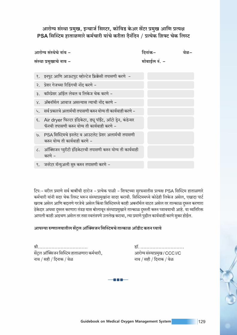


133Guidebook on Medical Oxygen Management System132 Guidebook on Medical Oxygen Management System
Annexure 6: Daily oxygen calculations
Sources ofoxygen storage
Approximateavailability of liquidmedical oxygen in
kilo liters
Approximateavailability of liquidmedical oxygen in
liters (x1000)
Qty of cylinders Approximate
availability of oxygenin gaseous form
Remarks
Liquid medicaloxygen tank-1
5 5000 NA 43,50,000 For convertingLMO/Dura
Liters in gaseousform multiply by
860. 1 Litre=860 Litersgaseous oxygen
Liquid medicaloxygen tank-2
2 2000 NA 17,40,000
Liquid medicaloxygen Reservoir-1
0 NA 0
Dura Cylinder- 1 200 0NA
Dura Cylinder- 2 Filled
240 0NA
D-Type, Jumbocylinder (Filled)
1,12,00016NA NAFor jumbo cylindertype D 7000 Liters
B- Type, smallcylinder (Filled)
0NA NAFor cylinder type
B 1500 Liters
Total 62,02,000
Total Usable Oxygen after considering residualoxygen requirement to maintain pressure
48,37,560
Annexure Table 11: Daily oxygen calculation sheet based on oxygen storage sources
Output calculations Approximate average
consumption of devicesin LPM
Nos. of Patients
Approximate Totalconsumptions in gaseous
form in LPM
O Prong 2 3 10 30
O Mask 2 4 10 40
Non-Rebreather mask 6 10 60
BiPAP 12 10 120
NIV FIO 2 50 10 500
Intubation FIO 2 25 10 250
HFNO (Not recommendedand should be phased down) 50 10 500
Total 70 1500
Annexure Table 12: Daily oxygen calculation sheet based on output sources
(Note : Calculation sheet will be provided as per user demand)
Annexure 7: Safety training check lists
Checklist for ensuring training on following aspects:
Training topic Trainingdone
Trainingdate
TrainerSignature
1. SAFETY EQUIPMENT
1.1. Has the appropriate Personal Protective Equipment been given to the employee?
- appropriate work clothes- boots/shoes- gloves- eye protection- hearing protection- hard hat
1.2. Have the rules regarding wearing of personal protectiveequipment been explained?
1.3. Does employee know that special protective clothing impermeable gloves, apron or suit, boots, goggles, face shield) must be worn when work is being done on caustic/acid installations or with solvents and where it can be obtained?
1.5. Has employee been told that damaged or unserviceable personal protective equipment must be replaced and that any damage to safety equipment must be reported to his/her supervisor?
1.4. Does employee know that clothing contaminatedwith caustic or acid has to be removed carefully?
1.6. Has employee been told that emergency equipment must not be used for routine jobs?
1.7. Has employee been shown where emergency showers andeyewash devices are located and how to use them?
2.1. Have all specific documents relevant to the job been given toemployee. i.e. Risk evaluations, Emergency instructions?
2.3. Has the meaning of all relevant safety signs been explained?
1.8. Does employee know why showers and eyewash bottlesare provided in some plant areas and the importance of preventing their misuse?
1.9. Has employee been told that it is dangerous to wipe his/hereyes or face with hands which may have come into contactwith chemicals or solvents?
1.10. Does employee know where self contained breathing apparatus, canisters and safety harness are kept and that they can only by used by trained personnel?
2. HAZARDS
2.2. Have the Work Instructions which concern employee'sparticular work and general matters been pointed out to him?Has employee read and understood them?
2.4. Have the applicable leaflets been commented? Have respective test been already filled? The minimum percentage of right answers has been reached? Failed questions have been commented?Any relevant safety booklets, videos.. etc should be used at this stage.

135Guidebook on Medical Oxygen Management System134 Guidebook on Medical Oxygen Management System
Training topic Trainingdone
Trainingdate
TrainerSignature
2.5. Does employee know the hazards associated with:Ÿ Oxygen plus oil, grease or other flammable or organic substances?Ÿ Acetylene or hydrocarbons in liquid oxygen (air separation plants
only)?Ÿ Liquid oxygen spillages on black top (asphalt)?Ÿ Oxygen deficiency which can be created by spillage or venting of
nitrogen or argon or confined spaces?Ÿ Oxygen enrichment due to spillage or venting?Ÿ Improper use of plant utilities, such as steam and compressed air?
2.11 Has the site emergency plan been explained including employee's particular role?
2.8. Does employee know that he/she must not bring matches, transistor, radios or other unapproved electrical devices, lighters or smoking materials within the boundary of DA and hydrogen storage and production areas? (DA = Dissolved Acetylene).
2.10 Have instructions been given in emergency procedures relevant to employee's job and does employee know the position of emergency stop buttons and emergency shut-off valves?
2.14 Does employee know how to identify the contents of cylinders by:Ÿ The written word (label)?Ÿ Colour code?Ÿ Valve type?Ÿ Pressure test dates?Ÿ Max. allowed working pressure?
2.9. Is employee aware of the instructions for action in case of fire...?Does employee know the location of fire extinguishers, hydrants and hoses?Has employee been given a demonstration of the use of appropriate fire extinguishers and hoses?Does the employee know the location and sound of the fire and evacuation alarms?
2.12 Does employee know his/her meeting point in case of emergency?
2.13 Record here when present at a site emergency drill or training session.
2.15 Have the dangers of filling damaged cylinders been explained to him?
2.16 Have the dangers of over pressurizing cylinders been explained?
2.17 Have the dangers of allowing an out of standard cylinder to bedispatched been explained (i.e. empty, uncapped, incorrect labels...)?
2.18 Has the procedure for reporting safety hazards been explained to employee?
2.19 Has employee been instructed to report gas leaks on equipment and faulty connections?
2.7. Does employee fully understand hazards associated with flames / sparks and that smoking is only allowed in certain areas which have been pointed out to him
2.6. Does he/she know that hot work, including the use of naked flames may only be carried out in certain specified areas which have been pointed out to him/her, or after the issue of the appropriate Work Permit?
Training topic Trainingdone
Trainingdate
TrainerSignature
2.20 Does employee know what to do when cryogenic transfer hoses and/or high pressure filling hoses rupture?
2.21 Does employee know the dangers of continued exposure ofhands and other parts of the body to solvents?
2.22 Does employee know that there are approved skin cleansers,and where to find them?
3.1. Has employee been instructed in the proper methods of breaking into lines?
2.23 Is employee aware of the role he/she is expected to play inhousekeeping of the area or section in which he/she works andthe importance of it in prevention of accidents
3.2. Does employee know where low voltage hand tools should be used?
3.4. Is employee familiar with the hazards associated with soldering,welding and flame-cutting and the correct precautionary measures?
3.6. Does employee know that special precautions are requiredfor working on roofs or in excavations?
3.5. Does employee know that he/she is required to wear additionaleye protection for certain tasks and/or in certain locations andhave these tasks and locations been explained to him?
3.7. Have rules relating to the use, care and return of ladders andlifting equipment been explained?
3.8. Has employee been told that access to fire equipment, emergency exits and electrical switchboards must be kept clear at all times?
3.3. Does employee know the rules governing the use of standardvoltage hand tools?
3.9. Has employee been instructed how to handle cylinders and other heavy objects correctly?
3.10 Does employee understand that only trained personnel can use cranes and lifting equipment?
3.11 Is employee aware that only qualified electricians can carry out electrical repairs, even though apparently trivial?
4.1. Has employee been told that a speed limit exists for all vehicles in the factory?
4.2. Has employee been told that only trained and authorized personnel are allowed to drive or operate forklift trucks?
4.4. Has employee been advised to keep clear of vehicles which might move without warning?
4.6. Does employee know that he/she should use pedestrian walkways when they are available/identified?
4.5. Has employee been instructed to report all unsafe conditions at customer's premises as well as in the factory?
4.3. Has employee been told that riding as a passenger on a forklift truck or the back of a lorry is forbidden?
4 TRAFFIC HAZARDS
3 MECHANICAL & ELECTRICAL HAZARDS
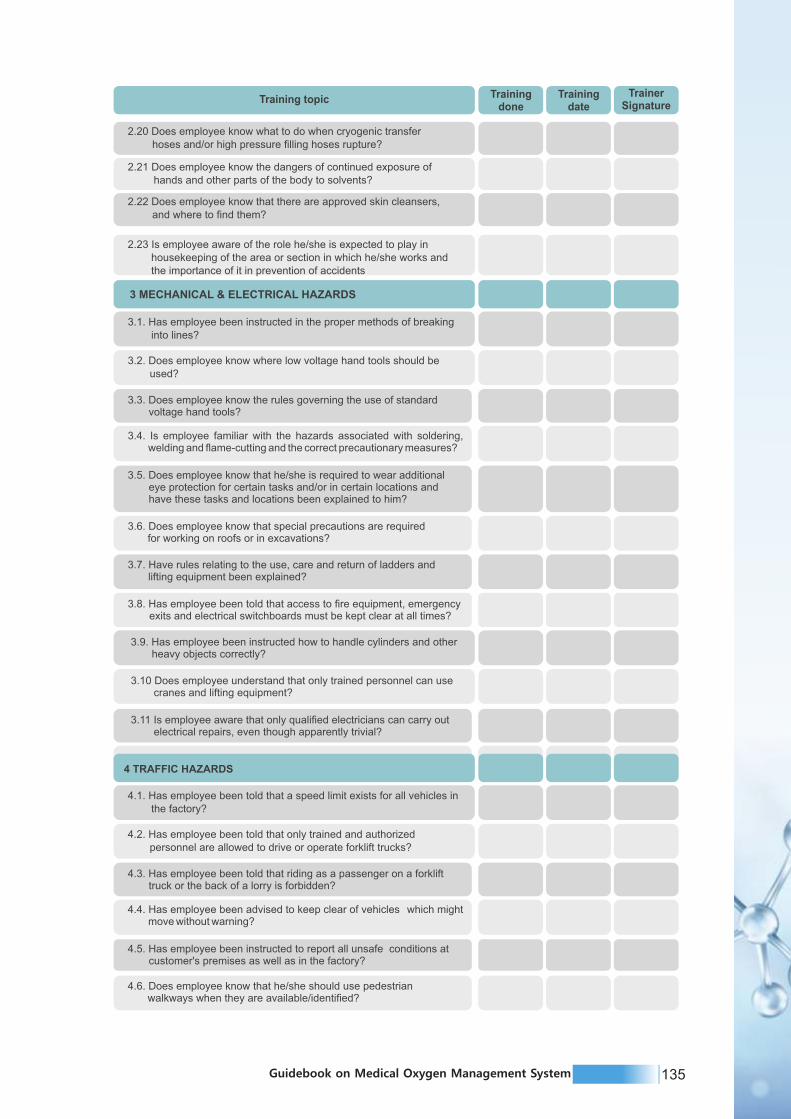

137Guidebook on Medical Oxygen Management System136 Guidebook on Medical Oxygen Management System
Training topic Trainingdone
Trainingdate
TrainerSignature
4.7. Does employee know who his/her department first-aider is and where he/she is located?
4.8. Does employee know that all injuries must be reported to his/her supervisor and a record made in the Accident Logbook as soon as possible?
4.9. Does employee know that if an injury occurs which necessitates his absence from work, he/she must, as soon as possible before the first day or shift of absence, inform his/her supervisor?
4.10. Does employee know that, during absence from work, he/she may be requested to attend medical examination by an appointed Doctor?
4.11. Does employee know that, on return to work, he/she may be required to be examined by an appointed Doctor?
5.1. Has the employee been given a copy of the Site Safety Policy?
5. SAFETY ORGANISATION
5.2. Has the Safety Policy been explained to employee?
5.4. Does employee know to whom he /she should address queries on Safety?
5.5. Has employee been advised about the function of the Safety Committee?
5.3. Has Safety organisation (Company and operating unit) been explained to employee?
Annexure 8: miyC/k vkWfDltupk ;ksX; okij dj.ksckcr ekxZn'kZd lwpuk

139Guidebook on Medical Oxygen Management System138 Guidebook on Medical Oxygen Management System

139Guidebook on Medical Oxygen Management System138 Guidebook on Medical Oxygen Management System

141Guidebook on Medical Oxygen Management System140 Guidebook on Medical Oxygen Management System

141Guidebook on Medical Oxygen Management System140 Guidebook on Medical Oxygen Management System

143Guidebook on Medical Oxygen Management System142 Guidebook on Medical Oxygen Management System

143Guidebook on Medical Oxygen Management System142 Guidebook on Medical Oxygen Management System

145Guidebook on Medical Oxygen Management System144 Guidebook on Medical Oxygen Management System

145Guidebook on Medical Oxygen Management System144 Guidebook on Medical Oxygen Management System

147Guidebook on Medical Oxygen Management System146 Guidebook on Medical Oxygen Management System
Annexure 9: Oxygen Audit Form

147Guidebook on Medical Oxygen Management System146 Guidebook on Medical Oxygen Management System
Annexure 9: Oxygen Audit Form

149Guidebook on Medical Oxygen Management System148 Guidebook on Medical Oxygen Management System

149Guidebook on Medical Oxygen Management System148 Guidebook on Medical Oxygen Management System

151Guidebook on Medical Oxygen Management System150 Guidebook on Medical Oxygen Management System

151Guidebook on Medical Oxygen Management System150 Guidebook on Medical Oxygen Management System

153Guidebook on Medical Oxygen Management System152 Guidebook on Medical Oxygen Management System

153Guidebook on Medical Oxygen Management System152 Guidebook on Medical Oxygen Management System

155Guidebook on Medical Oxygen Management System154 Guidebook on Medical Oxygen Management System

155Guidebook on Medical Oxygen Management System154 Guidebook on Medical Oxygen Management System

157Guidebook on Medical Oxygen Management System156 Guidebook on Medical Oxygen Management System
Annexure 10: Commonly needed Tools for repair and maintenance
of various oxygen systems:
Cycle pressure gauge Axial / angle seated valves forcycle operation, Angle seat valve
for cycle operation
Outlet to product tank Feed air pressure regulator(without or with filter)
Safety relief valves Exhaust pipe - super silencer
Brazing Torch
Spanner Set Screw Drivers
Cylinder Keys
Pipe Wrench Adjustable Spaner
Brazing Torch
Spanner & Tools
Gas Outlets Regulators Shut -off Valve

159Guidebook on Medical Oxygen Management System158 Guidebook on Medical Oxygen Management System
References
1. https://www.ehs.ufl.edu/programs/lab/cryogens/oxygen/
2. https://www.lindeus.com/-/media/corporate/praxairus/documents/sds/oxygen/liquid-
oxygen-medipure-gas-o2-safety-data-sheet-sds-p4637.pdf?la=en
3. Department of health - Medical gases Health Technical Memorandum 02-01: Medical gas
pipeline systems http://www.bcga.co.uk/assets/HTM_02-01_Part_A.pdf
4. https://www.p-mgs.com/en/products/source-medical-equipment/liquid-oxygen-storage-tank
5. https://www.airproducts.com/-/media/airproducts/files/en/900/900-13-078-us-liquid-oxygen-
safetygram-6.pdf?la=en&hash=186006835357D54E196DF13FF41DB3B4
6. PESO - https://peso.gov.in/web/smpv-u-rules-2016
7. WHO - WHO-UNICEF Technical specifications and guidance for oxygen therapy devices.
https://www.who.int/medical_devices/publications/tech_specs_oxygen_therapy_devices/en/
8. Technical specifications for Pressure Swing Adsorption (PSA) Oxygen Plants, Interim guide,
WHO
9. Online tender of PSA Oxygen Generation plant at public facilities, Central Medical Services
Society, MOHFW, GOI
10. Installation, Operation and maintenance manual – PSA type Oxygen Generating plant,
Trident
11. https://www.sciencedirect.com/topics/engineering/pressure-swing-adsorptionth12. Department order D.O. No. F. IIo. S.12035lL6l2O2L-Proc-I (Addl PSA) Dated 24 May, 2O21
13. Hardavella, G., Karampinis, I., Frille, A., Sreter, K., & Rousalova, I. (2019). Oxygen devices
and delivery systems. Breathe (Sheffield, England), 15(3), e108–e116.
https://doi.org/10.1183/20734735.0204-2019
14. Safety Training Of Employees - Asia Industrial Gases Association
http://www.asiaiga.org/uploaded_docs/AIGA%20009_10%20Safety%20training%20of%20
employees%20.pdf
15. Safe Installation and Operation of Psa and Membrane Oxygen And Nitrogen Generators -
Asia Industrial Gases Association
http://www.asiaiga.org/uploaded_docs/AIGA%20060_11%20PSA%20%20Membrane%20
O2%20N2%20generators_reformated%20Jan%2012.pdf
16. Fire Hazards Of Oxygen And Oxygen-Enriched Atmospheres - European Industrial Gases
Association AISBL https://eiga.eu/publications/eiga-documents/doc-0418-fire-hazards-of-
oxygen-and-oxygen-enriched-atmospheres/
17. https://arogya.maharashtra.gov.in/Site/Uploads/Tenders/db34f3ee-d081-405e-a6c0-
f76388b688c586%20CENTRALIZED%20OXYGEN.pdf
18. WHO Priority medical devices list for the COVID-19 response and associated technical
specifications-19 November 2020 https://www.who.int/publications/i/item/WHO-2019-nCoV-
MedDev-TS-O2T.V2
19. http://www.dgmhup.gov.in/Documents/Oxygen_Guidelines_and_Guidebook_Correction.pdf
20. https://www.healthcentral.com/article/the-three-types-of-oxygen-therapy-for-copd
21. https://www.inoxindia.com/inoxindia/covid19.php
22. Design of liquid oxygen storage tank with welded joints & its Safety - Bala Parandhama Raju
M1 , T. Mastaniah
http://www.ijmer.com/papers/Vol5_Issue4/Version-4/B0504_04-0510.pdf
23 Unit Conversion Data for Oxygen. Universal Industrial Gases Inc. Accessed at
http://www.uigi.com/o2_conv.html in December 2020
24. Sarangi S, Babbar S, Taneja D. Safety of the medical gas pipeline system. J Anaesthesiol Clin
Pharmacol. https://www.joacp.org/text.asp?2018/34/1/99/227571
Coper Pipe & Its Joints Coper Pipe & Its Joints
Manifold Gauges for MGPS System Pressure Release Valve for LMO
Cryogenic Valves Cryogenic Vacuum valves
Cryogenic Liquid Transfer Line Cryogenic Gloves
Annexure Figure 1: Commonly needed Tools for repair and maintenance of various oxygen systems

159Guidebook on Medical Oxygen Management System160 Guidebook on Medical Oxygen Management System
N O T E S

JULY 2021