The Effect of Grinding Wheel Contact Stiffness on Plunge ...
27
inventions Article The Effect of Grinding Wheel Contact Stiffness on Plunge Grinding Cycle Fukuo Hashimoto 1, * and Hiroto Iwashita 2 1 Advanced Finishing Technology Ltd., Akron, OH 44319, USA 2 Toba Engineering, Saku, Nagano 384-2101, Japan; [email protected] * Correspondence: [email protected] Received: 16 November 2020; Accepted: 16 December 2020; Published: 16 December 2020 Abstract: This paper presents the effect of grinding wheel contact stiffness on the plunge grinding cycle. First, it proposes a novel model of the generalized plunge grinding system. The model is applicable to all plunge grinding operations including cylindrical, centerless, shoe-centerless, internal, and shoe-internal grinding. The analysis of the model explicitly describes transient behaviors during the ramp infeed and the spark-out in the plunge grinding cycle. Clarification is provided regarding the premise that the system stiffness is composed of machine stiffness and wheel contact stiffness, and these stiffnesses significantly affect productivity and grinding accuracy. The elastic deflection of the grinding wheel is accurately measured and formulas for representing the deflection nature under various contact loads are derived. The deflection model allows us to find the non-linear contact stiffness with respect to the normal load. The contact stiffnesses of four kinds of grinding wheels with different grades and bond materials are presented. Both cylindrical grinding and centerless grinding tests are carried out, and it is experimentally revealed that the time constant at ramp infeed and spark-out is significantly prolonged by reducing the grinding force. It is verified that a simulation of the grinding tests using the proposed model can accurately predict critical parameters like forces and machine deflection during plunge grinding operations. Finally, this paper provides a guideline for grinding cycle design in order to achieve the required productivity and grinding accuracy. Keywords: grinding; grinding wheel; contact stiffness; plunge grinding; grinding machine 1. Introduction In the plunge grinding of cylindrical components, the grinding performance is assessed by productivity and grinding accuracy. The productivity in the number of finished parts per unit time is determined by the grinding cycle time consisting of the plunge-infeed time and the spark-out time. As the actual infeed to the CNC command has a time delay, the required cycle time is largely affected by the system stiffness. On the other hand, the grinding accuracy is significantly governed by the system stiffness. In fact, the actual depth of cut always lower than the command value due to the elastic deflections of the grinding system. These deflections become the root cause of geometrical errors such as size error, profile error, roundness error, etc., in the ground products. The system stiffness is composed of the grinding machine stiffness and the contact stiffness of grinding wheel. The machine stiffness has a linear characteristic under general grinding conditions, and it is relatively easy to integrate it to the grinding system. However, it is well known that the contact deflection in wheel-workpiece interactions shows a non-linear characteristic. As the result, the process parameters like grinding forces in the grinding cycle exhibit complicated behaviors and the phenomena make it difficult to design a proper grinding cycle. Thus, it is crucial to take the influence of contact stiffness on the grinding processes into account in order to achieve the required productivity and accuracy. Inventions 2020, 5, 62; doi:10.3390/inventions5040062 www.mdpi.com/journal/inventions
-
Upload
khangminh22 -
Category
Documents
-
view
0 -
download
0
Transcript of The Effect of Grinding Wheel Contact Stiffness on Plunge ...

inventions
Article
The Effect of Grinding Wheel Contact Stiffness onPlunge Grinding Cycle
Fukuo Hashimoto 1,* and Hiroto Iwashita 2
1 Advanced Finishing Technology Ltd., Akron, OH 44319, USA2 Toba Engineering, Saku, Nagano 384-2101, Japan; [email protected]* Correspondence: [email protected]
Received: 16 November 2020; Accepted: 16 December 2020; Published: 16 December 2020 �����������������
Abstract: This paper presents the effect of grinding wheel contact stiffness on the plunge grindingcycle. First, it proposes a novel model of the generalized plunge grinding system. The model isapplicable to all plunge grinding operations including cylindrical, centerless, shoe-centerless, internal,and shoe-internal grinding. The analysis of the model explicitly describes transient behaviors duringthe ramp infeed and the spark-out in the plunge grinding cycle. Clarification is provided regardingthe premise that the system stiffness is composed of machine stiffness and wheel contact stiffness,and these stiffnesses significantly affect productivity and grinding accuracy. The elastic deflectionof the grinding wheel is accurately measured and formulas for representing the deflection natureunder various contact loads are derived. The deflection model allows us to find the non-linear contactstiffness with respect to the normal load. The contact stiffnesses of four kinds of grinding wheels withdifferent grades and bond materials are presented. Both cylindrical grinding and centerless grindingtests are carried out, and it is experimentally revealed that the time constant at ramp infeed andspark-out is significantly prolonged by reducing the grinding force. It is verified that a simulation ofthe grinding tests using the proposed model can accurately predict critical parameters like forces andmachine deflection during plunge grinding operations. Finally, this paper provides a guideline forgrinding cycle design in order to achieve the required productivity and grinding accuracy.
Keywords: grinding; grinding wheel; contact stiffness; plunge grinding; grinding machine
1. Introduction
In the plunge grinding of cylindrical components, the grinding performance is assessed byproductivity and grinding accuracy. The productivity in the number of finished parts per unit timeis determined by the grinding cycle time consisting of the plunge-infeed time and the spark-out time.As the actual infeed to the CNC command has a time delay, the required cycle time is largely affectedby the system stiffness. On the other hand, the grinding accuracy is significantly governed by thesystem stiffness. In fact, the actual depth of cut always lower than the command value due to the elasticdeflections of the grinding system. These deflections become the root cause of geometrical errors suchas size error, profile error, roundness error, etc., in the ground products.
The system stiffness is composed of the grinding machine stiffness and the contact stiffness ofgrinding wheel. The machine stiffness has a linear characteristic under general grinding conditions,and it is relatively easy to integrate it to the grinding system. However, it is well known that thecontact deflection in wheel-workpiece interactions shows a non-linear characteristic. As the result, theprocess parameters like grinding forces in the grinding cycle exhibit complicated behaviors and thephenomena make it difficult to design a proper grinding cycle. Thus, it is crucial to take the influenceof contact stiffness on the grinding processes into account in order to achieve the required productivityand accuracy.
Inventions 2020, 5, 62; doi:10.3390/inventions5040062 www.mdpi.com/journal/inventions

Inventions 2020, 5, 62 2 of 27
There are many publications related to the wheel contact stiffness. However, no published paperhas described the effect of wheel contact stiffness on the plunge grinding cycle. Much research hasbeen done in the area of grinding wheel deflection. Hahn [1] first suggested that the deflection ofthe wheel surface could explain the differences in material removal rates arising from the conformitydifference between internal and external grinding. Peklenik [2] proposed the use of the thermocouplemethod to measure grinding temperature and contact length. He showed a difference in the effectivenumber of cutting points with the wheel grade which attributed to differences in wheel elasticity.Snoeys and Wang [3] carried out static loading tests to verify their model of grain mounted on springsand concluded that the model provided more realistic values for the deflection of the wheel.
Brown, Saito, and Shaw [4] analyzed the influence of elastic deflection on contact length andestablished a contact length model using Hertzian theory. Kumar and Shaw [5] analyzed the deflectionof the grinding wheel and workpiece separately and concluded that the predominant deflection wasdue to the grinding wheel, not the workpiece. Krug and Honcia [6] estimated the amount of localwheel deflection and found that it would be on the order of 1 µm for a vitrified wheel and 2.5 µm for aresinoid wheel.
Nakayama, Brecker, and Shaw [7] conducted experiments to measure the deflection associatedwith an individual grain and showed that the local elastic deformation of the grain was the sameorder of magnitude as the undeformed chip thickness. Nakayama [8] observed deflection of thegrains that behaved as if the grains on the wheel were supported by non-linear springs. Zhou andLutterwelt [9] presented a measuring method to identify the maximum contact length and local lengthat the wheel-work contact zone. Rowe et al. [10] proposed a model based on the theory of cylinders incontact, including the effect of grains, and explained why measured contact length can be 50% to 200%greater than geometric contact length.
Hucker, Farris, and Chandrasekar [11] conducted grinding tests to measure machine and wheeldeflection under various grinding loads and concluded that the contact stiffness of CBN wheels isabout three times greater than that of Al2O3 wheels. Yamada et al. [12,13] proposed a model of awheel consisting of rigid body and spring elements and measured the contact stiffness of the wheelunder both stationary conditions and grinding operations. Papanikolaou and Salonitis [14] applieda three-dimensional molecular dynamics simulation to investigate the effect of contact stiffness ongrinding processes under various grinding speeds.
Self-excited regenerative chatter vibrations are another aspect of the contact stiffness of the wheelthat havet been extensively investigated. Chatter vibrations are generally associated with the dynamiccompliances of the grinding machine, and a great deal of research has been devoted to understandingthese instabilities [15–19]. Snoeys and Brown [20] proposed a model representing work-regenerativeand wheel-regenerative chatter vibrations in cylindrical grinding. The model was represented by ablock diagram with feedback loops of machine compliances, including the contact stiffness of the wheel.
Inasaki [21] experimentally investigated wheel contact stiffness with hard-spring characteristicsand pointed out that it changed with grinding conditions such as speed ratio, depth of cut, etc. Hediscussed the effects of contact stiffness on the stability of the chatter vibrations. Miyashita, Hashimoto,and Kanai [22] analyzed the dynamic stability of a centerless grinding system and proposed a newsetup index for suppressing work-regenerative chatter vibrations. Their model indicated that thecontact stiffnesses of both the grinding wheel and regulating wheel had significant influence on chattervibrations. Hashimoto, Kanai, and Miyashita [23] investigated the growing mechanism of chattervibrations in cylindrical grinding and proposed a stabilization index related to the wheel contact stiffnessfor selecting the grinding wheel specifications. A parameter related to the dynamic time constant wasintroduced and discussed the in-process measurement of the time constant to predict the stability of thechatter vibrations.
In the field of grinding cycle investigations, King and Hahn [24] analyzed a cylindrical grindingsystem and introduced a concept of time constant which was applicable to the cylindrical grinding, butnot to centerless grinding. Malkin and Koren [25] investigated the plunge grinding cycle and proposed

Inventions 2020, 5, 62 3 of 27
accelerated spark-out to reduce the cycle time. Chiu and Malkin [26] presented a simulation of thegrinding parameters specific to infeed cylindrical grinding.
The aforementioned research concentrated primarily on the modeling and measurement of realcontact length and the deflection characteristics at the local contact zone of the wheel. This literaturerevealed the nature of wheel elastic deflection and provided valuable evidence about contact stiffnesswith hard-spring characteristics. However, the extensive knowledge gleaned about wheel deflectionhas been little used in practical applications. Current practices for determining the operational grindingconditions of the grinding cycle still largely rely on a cut-and-try method. One reason for this may bethe disconnection between the scientific parameters used in past research and the practical parametersrequired for real-world grinding operations.
It is necessary to establish practical procedures for setting up the proper grinding conditionsincluding grinding stocks, infeed rates, spark-out time, and the selection of the grinding wheel.Furthermore, clear guidelines for designing the grinding cycle that take the effect of contact stiffness ongrinding performance into account are indispensable.
This paper presents the effect of grinding wheel contact stiffness on the plunge grinding cycle. Italso provides guidelines for the design of the grinding cycle. First, the generalized plunge grindingsystem including cylindrical, centerless, shoe-centerless, internal, and shoe-internal grinding is explicitlydescribed and analyzed in terms of system outputs corresponding to the inputs of the plunge grindingconditions. The analysis describes the influence of system stiffness on the time constant that governsthe transient behaviors of the process parameters such as forces, power, and machine elastic deflection.Additionally, it clarifies that system stiffness is composed of machine stiffness and wheel contactstiffness. These stiffnesses significantly affect the grinding performance indicators such as productivityand grinding accuracy.
The elastic deflection of the grinding wheel is accurately measured and a function for representingthe deflection nature under various contact loads is derived. The function allows us to find the non-linearcontact stiffness with respect to the normal load. The contact stiffnesses of four kinds of grindingwheels with different grades and bond materials are presented, and the changes in contact stiffnessafter dressing are discussed.
Experimental tests for both cylindrical grinding and centerless grinding are conducted, andit is experimentally confirmed that the time constant at ramp infeed and spark-out is significantlyprolonged by reducing the grinding force. It is verified that a simulation of the grinding tests using theproposed model can accurately predict critical parameters like forces, machine deflection, and systemstiffness during plunge grinding operations. Finally, this paper emphasizes that it is vital to take theeffect of wheel contact stiffness into consideration during the design of the plunge grinding cycle.
2. Plunge Grinding System and the Grinding Cycle
2.1. Plunge Grinding System
In order to investigate the effect of the grinding wheel’s elastic contact deflection on the plungegrinding process, it is necessary to clarify the relationship between the operational setup parametersand the machine characteristics (including the abrasive tools). There are several methods of plungeinternal and external grinding, as shown in Figure 1. The grinding method parameter c is used toidentify the influence of the amount of infeed on the size reduction of the workpieces. In the centerlessgrinding and shoe centerless grinding methods (Figure 1d,e), the amount of infeed becomes thediameter reduction of the workpieces and c = 0.5 is denoted. On the other hand, in Figure 1a–c,f,the amount of infeed gives the radial reduction on the external or internal ground surface of theworkpieces, and c = 1.0 is assigned for these methods.

Inventions 2020, 5, 62 4 of 27Inventions 2020, 5, 62 4 of 29
Figure 1. Plunge grinding operations and the method parameter c. (a) Center type cylindrical grinding; (b) Chuck type cylindrical grinding; (c) Internal grinding; (d) Centerless grinding; (e) Shoe centerless grinding; (f) Shoe internal grinding.
In plunge grinding, as shown in Figure 1, the grinding wheel mounted on the infeed slide is fed into the workpiece as a command infeed If. The actual infeed 𝑟 can be expressed by: 𝑟 (𝑡) = 𝐼 (𝑡) − 𝑑 (𝑡) (1)
where t is the grinding time and 𝑑 is the elastic deflection of the grinding system including the contact deflection of grinding wheel. The actual infeed rate 𝑓 is: 𝑓 (𝑡) = ( ). (2)
The SMRR (specific material removal rate) 𝑄 is expressed by: 𝑄 (𝑡) = 𝑐 ∙ 𝜋 ∙ 𝑑 ∙ 𝑓 (𝑡) (3)
where 𝑑 is the internal or external diameter of the workpiece. The MRR (material removal rate) 𝑄 is: 𝑄 (𝑡) = 𝑏 ∙ 𝑄 (𝑡) (4)
where b is the grinding width. The normal grinding force 𝐹 can be written as follows: 𝐹 (𝑡) = 𝜂 ∙ 𝑢𝑣 ∙ 𝑄 (𝑡) (5)
where η is the force ratio of Fn to tangential force Ft, 𝑣 is the grinding speed, and u is the specific energy. The elastic deflection 𝑑 of the grinding system in the infeed direction can be expressed by: 𝑑 (𝑡) = 1𝑘 ∙ 𝐹 (𝑡) (6)
where 𝑘 is the equivalent system stiffness. Equivalent system stiffness 𝑘 consists of the stiffness of each machine structure involved in
the grinding system and the stiffness of the grinding wheel. The main components of equivalent stiffness 𝑘 are shown in Figure 2. Material removal by grinding generates a normal grinding force 𝐹 , as described in Equation (5). The force 𝐹 gives the elastic deflection 𝑑 , which is determined by the system stiffness 𝑘 . Figure 2a,b illustrate the stiffnesses 𝑘 𝑎𝑛𝑑 𝑘 of the grinding wheel
Figure 1. Plunge grinding operations and the method parameter c. (a) Center type cylindrical grinding;(b) Chuck type cylindrical grinding; (c) Internal grinding; (d) Centerless grinding; (e) Shoe centerlessgrinding; (f) Shoe internal grinding.
In plunge grinding, as shown in Figure 1, the grinding wheel mounted on the infeed slide is fedinto the workpiece as a command infeed If. The actual infeed rw can be expressed by:
rw(t) = I f (t) − de(t) (1)
where t is the grinding time and de is the elastic deflection of the grinding system including the contactdeflection of grinding wheel. The actual infeed rate fi is:
fi(t) =drw(t)
dt. (2)
The SMRR (specific material removal rate) Qw′ is expressed by:
Qw′(t) = c·π·dw· fi(t) (3)
where dw is the internal or external diameter of the workpiece. The MRR (material removal rate) Qw is:
Qw(t) = b·Qw′(t) (4)
where b is the grinding width. The normal grinding force Fn can be written as follows:
Fn(t) =η·uvs·Qw(t) (5)
where η is the force ratio of Fn to tangential force Ft, vs is the grinding speed, and u is the specificenergy. The elastic deflection de of the grinding system in the infeed direction can be expressed by:
de(t) =1
keq·Fn(t) (6)
where keq is the equivalent system stiffness.

Inventions 2020, 5, 62 5 of 27
Equivalent system stiffness keq consists of the stiffness of each machine structure involved in thegrinding system and the stiffness of the grinding wheel. The main components of equivalent stiffnesskeq are shown in Figure 2. Material removal by grinding generates a normal grinding force Fn, asdescribed in Equation (5). The force Fn gives the elastic deflection de, which is determined by the systemstiffness keq. Figure 2a,b illustrate the stiffnesses ks and kw of the grinding wheel support system and theworkpiece support system, respectively. Figure 2c shows the stiffness kwo of workpiece itself, whichcannot be ignored when kwo is low (as in the case of thin-wall rings). Figure 2d shows the local deflectionδc at the contact area between the grinding wheel and the workpiece, and kc is the contact stiffness ofthe grinding wheel.
Inventions 2020, 5, 62 5 of 29
support system and the workpiece support system, respectively. Figure 2c shows the stiffness 𝑘 of workpiece itself, which cannot be ignored when 𝑘 is low (as in the case of thin-wall rings). Figure 2d shows the local deflection 𝛿 at the contact area between the grinding wheel and the workpiece, and 𝑘 is the contact stiffness of the grinding wheel.
The equivalent system stiffness 𝑘 is expressed by: 1𝑘 = 1𝑘 1𝑘 (7)
where 𝑘 is the mechanical stiffness represented by the stiffness of each mechanical structure related to the grinding system: 1𝑘 = 1𝑘 1𝑘 1𝑘 ⋯ = 1𝑘 (8)
where 𝑘 is the i-th stiffness of the mechanical structure relevant to the grinding system and n is the degrees of freedom. Since each component of mechanical stiffness 𝑘 has a linear spring characteristic, 𝑘 remains a constant during the plunge grinding process. On the other hand, the wheel contact stiffness 𝑘 has the non-linear characteristics referred to as “hard-spring.” As a result, the equivalent system stiffness 𝑘 behaves as a non-linear spring, which changes in stiffness value depending on the grinding conditions. As such, it is crucial to take the spring characteristics at the contact area of the grinding wheel into account in the design of the plunge grinding cycle.
Figure 2. Components of equivalent system stiffness in plunge grinding system. (a) Stiffness of grinding wheel head; (b) Stiffness of work head; (c) Stiffness of workpiece; (d) Contact stiffness of grinding wheel.
The deflection 𝑑 given by Equation (6) is fed back to Equation (1). Thus, the plunge grinding process can be described as a closed-loop system repeating Equations (1)–(6). By using Equations (3)–(5), Equation (6) can be rewritten as follows:
Figure 2. Components of equivalent system stiffness in plunge grinding system. (a) Stiffness of grindingwheel head; (b) Stiffness of work head; (c) Stiffness of workpiece; (d) Contact stiffness of grinding wheel.
The equivalent system stiffness keq is expressed by:
1keq
=1
km+
1kc
(7)
where km is the mechanical stiffness represented by the stiffness of each mechanical structure related tothe grinding system:
1km
=1ks
+1
kw+
1kwo
+ · · · =n∑
i=1
1kmi
(8)
where kmi is the i-th stiffness of the mechanical structure relevant to the grinding system and n is thedegrees of freedom. Since each component of mechanical stiffness km has a linear spring characteristic,km remains a constant during the plunge grinding process. On the other hand, the wheel contactstiffness kc has the non-linear characteristics referred to as “hard-spring.” As a result, the equivalentsystem stiffness keq behaves as a non-linear spring, which changes in stiffness value depending on the

Inventions 2020, 5, 62 6 of 27
grinding conditions. As such, it is crucial to take the spring characteristics at the contact area of thegrinding wheel into account in the design of the plunge grinding cycle.
The deflection de given by Equation (6) is fed back to Equation (1). Thus, the plunge grindingprocess can be described as a closed-loop system repeating Equations (1)–(6). By using Equations (3)–(5),Equation (6) can be rewritten as follows:
de(t) =c·π·dw·b·η·u
vs·keq· fi(t) = T· fi(t) (9)
where T is the time constant of the grinding system.
T =c·π·dw·b·η·u
vs·keq. (10)
The time constant T is one of the most critical parameters in the plunge grinding system.The Laplace transformation of Equations (1)–(6) leads to the following equations:
Rw(s) = I f (s) −De(s) (11)
Fi(s) = s·Rw(s) (12)
Qw′(s) = c·π·dw·Fi(s) (13)
Qw(s) = b·Qw′(s) (14)
Fn(s) =η·uvs·Qw(s) (15)
De(s) =1
keq·Fn(s) (16)
where s is the Laplace operator. Actual infeed Rw(s), actual infeed rate Fi(s), SMMR Qw′(s), normal
grinding force Fn(s), and elastic deflection De(s) are Laplace functions.Figure 3 shows a block diagram of the plunge grinding system representing the transfer functions
given by Equations (11)–(16). The plunge grinding system can be expressed by a closed-loop feedbacksystem. The transfer function G(s) of the system is represented by:
G(s) =Rw
I f(s) =
1c·π·dw·b·η·u
vs·keqs + 1
=1
Ts + 1. (17)
Inventions 2020, 5, 62 6 of 29
𝑑 (𝑡) = 𝑐 ∙ 𝜋 ∙ 𝑑 ∙ 𝑏 ∙ 𝜂 ∙ 𝑢𝑣 ∙ 𝑘 ∙ 𝑓 (𝑡) = 𝑇 ∙ 𝑓 (𝑡) (9)
where T is the time constant of the grinding system. 𝑇 = ∙ ∙ ∙ ∙ ∙∙ . (10)
The time constant T is one of the most critical parameters in the plunge grinding system. The Laplace transformation of Equations (1)–(6) leads to the following equations: 𝑅 (𝑠) = 𝐼 (𝑠) − 𝐷 (𝑠) (11) 𝐹 (𝑠) = 𝑠 ∙ 𝑅 (𝑠) (12) 𝑄 (𝑠) = 𝑐 ∙ 𝜋 ∙ 𝑑 ∙ 𝐹 (𝑠) (13) 𝑄 (𝑠) = 𝑏 ∙ 𝑄 (𝑠) (14)
𝐹 (𝑠) = 𝜂 ∙ 𝑢𝑣 ∙ 𝑄 (𝑠) (15)
𝐷 (𝑠) = 1𝑘 ∙ 𝐹 (𝑠) (16)
where s is the Laplace operator. Actual infeed 𝑅 (𝑠), actual infeed rate 𝐹 (𝑠), SMMR 𝑄 (𝑠), normal grinding force 𝐹 (𝑠), and elastic deflection 𝐷 (𝑠) are Laplace functions.
Figure 3 shows a block diagram of the plunge grinding system representing the transfer functions given by Equations (11)–(16). The plunge grinding system can be expressed by a closed-loop feedback system. The transfer function G(s) of the system is represented by: 𝐺(𝑠) = 𝑅𝐼 (𝑠) = 1𝑐 ∙ 𝜋 ∙ 𝑑 ∙ 𝑏 ∙ 𝜂 ∙ 𝑢𝑣 ∙ 𝑘 𝑠 1 = 1𝑇𝑠 1. (17)
Thus, plunge grinding can be represented by a first-order lag system with the time constant T given by Equation (10). The cut-off frequency 𝑓 (Hz) of the plunge grinding system is represented by: 𝑓 = . (18)
Figure 3. Block diagram of the plunge grinding system.
Figure 3. Block diagram of the plunge grinding system.

Inventions 2020, 5, 62 7 of 27
Thus, plunge grinding can be represented by a first-order lag system with the time constant Tgiven by Equation (10). The cut-off frequency fc (Hz) of the plunge grinding system is represented by:
fc =1
2πT. (18)
2.2. Analysis of Plunge Grinding Cycle
The plunge grinding cycle starts with a rapid forward infeed of the slide from the home position.Typically, the slide feed rate is then changed for rough, semi-finish or finish grinding. After infeedgrinding, spark-out grinding is performed in order to reduce the elastic deflection of the grindingsystem, followed by the rapid retraction of the slide to the home position. To study the effect of thewheel’s contact stiffness on the plunge grinding process, this paper focuses on a primary grindingcycle consisting of plunge grinding with a constant infeed rate followed by spark-out grinding.
The diagram in Figure 4a depicts the plunge grinding operation. The infeed slide is rapidly fedforward to position P from the home position H. Then, the infeed rate is changed to a constant infeedrate Ip at point P. At some point O, which is determined by the size of the incoming workpiece, thegrinding wheel mounted on the slide contacts the workpiece at the infeed rate Ip and plunge grindingstarts. At position A, the slide infeed is stopped and spark-out grinding starts. At point B, the slide israpidly retracted to the home position H. Figure 4b shows the primary cycle with plunge grindingtime tp and spark-out time (ts − tp).
Inventions 2020, 5, 62 7 of 29
2.2. Analysis of Plunge Grinding Cycle
The plunge grinding cycle starts with a rapid forward infeed of the slide from the home position. Typically, the slide feed rate is then changed for rough, semi-finish or finish grinding. After infeed grinding, spark-out grinding is performed in order to reduce the elastic deflection of the grinding system, followed by the rapid retraction of the slide to the home position. To study the effect of the wheel’s contact stiffness on the plunge grinding process, this paper focuses on a primary grinding cycle consisting of plunge grinding with a constant infeed rate followed by spark-out grinding.
The diagram in Figure 4a depicts the plunge grinding operation. The infeed slide is rapidly fed forward to position P from the home position H. Then, the infeed rate is changed to a constant infeed rate 𝐼 at point P. At some point O, which is determined by the size of the incoming workpiece, the grinding wheel mounted on the slide contacts the workpiece at the infeed rate 𝐼 and plunge grinding starts. At position A, the slide infeed is stopped and spark-out grinding starts. At point B, the slide is rapidly retracted to the home position H. Figure 4b shows the primary cycle with plunge grinding time 𝑡 and spark-out time (𝑡 − 𝑡 ).
Figure 4. Plunge grinding cycle. (a) Diagram of plunge grinding operations; (b) Primary cycle of plunge grinding.
During plunge grinding (0 𝑡 𝑡 ), the actual feed rate 𝑓 (𝑡) can be obtained by the following equations [27]: 0 𝑡 𝑡 : 𝑓 (𝑡) = 𝐼 1 − 𝑒 . (19)
𝑡 𝑡 𝑡 : 𝑓 (𝑡) = 𝐼 1 − 𝑒 ∙ 𝑒 ( ). (20)
The actual infeed position 𝑟 (𝑡) is: 0 𝑡 𝑡 : 𝑟 (𝑡) = 𝐼 𝑡 − 𝑇 1 − 𝑒 . (21)
𝑡 𝑡 𝑡 : 𝑟 (𝑡) = 𝐼 𝑡 − 𝑇 𝑒 ( ) − 𝑒 . (22)
The normal grinding force 𝐹 (𝑡) is: 0 𝑡 𝑡 : 𝐹 (𝑡) = 𝐼 ∙ 𝑘 ∙ 𝑇(1 − 𝑒 ). (23)
𝑡 𝑡 𝑡 : 𝐹 (𝑡) = 𝐼 ∙ 𝑘 ∙ 𝑇 1 − 𝑒 ∙ 𝑒 . (24)
The grinding power 𝑃 (𝑡) is:
Figure 4. Plunge grinding cycle. (a) Diagram of plunge grinding operations; (b) Primary cycle ofplunge grinding.
During plunge grinding(0 ≤ t ≤ tp
), the actual feed rate fi(t) can be obtained by the following
equations [27]:0 ≤ t ≤ tp : fi(t) = Ip
(1− e−
tT). (19)
tp ≤ t ≤ ts : fi(t) = Ip
(1− e−
tpT
)·e−
(t−tp)T . (20)
The actual infeed position rw(t) is:
0 ≤ t ≤ tp : rw(t) = Ip[t− T
(1− e−
tT)]
. (21)
tp ≤ t ≤ ts : rw(t) = Ip
[tp − T
(e−
(t−tp)T − e−
tpT
)]. (22)
The normal grinding force Fn(t) is:
0 ≤ t ≤ tp : Fn(t) = Ip·keq·T(1− e−
tT). (23)

Inventions 2020, 5, 62 8 of 27
tp ≤ t ≤ ts : Fn(t) = Ip·keq·T(1− e−
tpT
)·e−
(t−tp)T . (24)
The grinding power Pg(t) is:
0 ≤ t ≤ tp : Pg(t) =vs
η·Ip·keq·T
(1− e−
tT). (25)
tp ≤ t ≤ ts : Pg(t) =vs
η·Ip·keq·T
(1− e−
tpT
)·e−
(t−tp)T . (26)
The deflection de(t) causing the size and roundness error is obtained by:
0 ≤ t ≤ tp : de(t) = Ip·T(1− e−
tT). (27)
tp ≤ t ≤ ts : de(t) = Ip·T(1− e−
tpT
)·e−
(t−tp)T . (28)
When plunge grinding time tp is long enough compared to time constant T, the above Equations (20),(22), (24), and (26) for spark-out grinding can be approximately represented by the following equations:
tp ≤ t ≤ ts : fi(t) � Ip·e−(t−tp)
T . (29)
tp ≤ t ≤ ts : rw(t) � Ip
(tp − T·e−
(t−tp)T
). (30)
tp ≤ t ≤ ts : Fn(t) � Ip·keq·T·e−(t−tp)
T . (31)
tp ≤ t ≤ ts : Pg(t) �vs
η·Ip·keq·T·e−
(t−tp)T . (32)
tp ≤ t ≤ ts : de(t) � Ip·T·e−(t−tp)
T . (33)
Figure 5 is an example simulation of the plunge grinding process. The actual slide position rw(t)(Figure 5a) is calculated by Equations (21) and (22). The actual slide position delays the command andgradually catches up. Eventually, it attains the same slope as the command feed. The asymptote ofthe actual infeed curve intersects at time T on the horizontal axis. The position difference between thecommand feed and the actual feed represents the system deflection and is also the size error. The deflectionis reduced with increased spark-out time. The grinding power Pg(t) found by Equations (25) and(26) is the response to the ramp infeed command with a constant rate and the no-infeed command forthe spark-out.
Inventions 2020, 5, 62 8 of 29
0 𝑡 𝑡 : 𝑃 (𝑡) = 𝑣𝜂 ∙ 𝐼 ∙ 𝑘 ∙ 𝑇 1 − 𝑒 . (25)
𝑡 𝑡 𝑡 : 𝑃 (𝑡) = 𝑣𝜂 ∙ 𝐼 ∙ 𝑘 ∙ 𝑇 1 − 𝑒 ∙ 𝑒 . (26)
The deflection 𝑑 (𝑡) causing the size and roundness error is obtained by: 0 𝑡 𝑡 : 𝑑 (𝑡) = 𝐼 ∙ 𝑇 1 − 𝑒 . (27)
𝑡 𝑡 𝑡 : 𝑑 (𝑡) = 𝐼 ∙ 𝑇 1 − 𝑒 ∙ 𝑒 ( ). (28)
When plunge grinding time 𝑡 is long enough compared to time constant T, the above Equations (20), (22), (24), and (26) for spark-out grinding can be approximately represented by the following equations: 𝑡 𝑡 𝑡 : 𝑓 (𝑡) ≅ 𝐼 ∙ 𝑒 ( ). (29)
𝑡 𝑡 𝑡 : 𝑟 (𝑡) ≅ 𝐼 (𝑡 − 𝑇 ∙ 𝑒 ( )). (30)
𝑡 𝑡 𝑡 : 𝐹 (𝑡) ≅ 𝐼 ∙ 𝑘 ∙ 𝑇 ∙ 𝑒 . (31)
𝑡 𝑡 𝑡 : 𝑃 (𝑡) ≅ 𝑣𝜂 ∙ 𝐼 ∙ 𝑘 ∙ 𝑇 ∙ 𝑒 . (32)
𝑡 𝑡 𝑡 : 𝑑 (𝑡) ≅ 𝐼 ∙ 𝑇 ∙ 𝑒 ( ). (33)
Figure 5 is an example simulation of the plunge grinding process. The actual slide position 𝑟 (𝑡) (Figure 5a) is calculated by Equations (21) and (22). The actual slide position delays the command and gradually catches up. Eventually, it attains the same slope as the command feed. The asymptote of the actual infeed curve intersects at time T on the horizontal axis. The position difference between the command feed and the actual feed represents the system deflection and is also the size error. The deflection is reduced with increased spark-out time. The grinding power 𝑃 (𝑡) found by Equations (25) and (26) is the response to the ramp infeed command with a constant rate and the no-infeed command for the spark-out.
Figure 5. Simulation of plunge grinding processes (conditions: c = 1.0, dw = 177.8 mm, b = 30 mm, vs. = 45 m/s, η = 2.0, keq = 2421 N/mm, u = 26.7 J/mm³, S = 0.3 mm, Qw’ = 2.0 mm³/mm·s, Ip = 3.58 μm/s, tp = 41.9 s, ts = 56.9 s). (a) Infeed slide position; (b) Grinding power.
The power is gradually increased and finally reaches a constant value. The time constant T is defined as the time when the power reaches 63.2% (1 − 𝑒 = 0.632) of the final value. The definition
Figure 5. Simulation of plunge grinding processes (conditions: c = 1.0, dw = 177.8 mm, b = 30 mm, vs.= 45 m/s, η = 2.0, keq = 2421 N/mm, u = 26.7 J/mm3, S = 0.3 mm, Qw′ = 2.0 mm3/mm·s, Ip = 3.58 µm/s,tp = 41.9 s, ts = 56.9 s). (a) Infeed slide position; (b) Grinding power.

Inventions 2020, 5, 62 9 of 27
The power is gradually increased and finally reaches a constant value. The time constant T isdefined as the time when the power reaches 63.2% (1− e−1 = 0.632) of the final value. The definitionof T can be applied to the spark-out grinding shown in Figure 5b. The transient curves of otherparameters, including the actual infeed rate fi(t), the normal grinding force Fn(t), and the deflectionde(t), follow the curve of Figure 5b.
2.3. The Effect of Grinding Wheel Contact Stiffness on the Plunge Grinding Process
As mentioned above, system stiffness keq consists of a constant mechanical stiffness km and contactstiffness kc of the grinding wheel with non-linear characteristics. In this section, the effect of systemstiffness (particularly wheel contact stiffness kc) on the plunge grinding process is discussed.
Figure 6 shows the effect of system stiffness on the plunge grinding process. The response of thegrinding power Pg is increased with increased system stiffness. Accordingly, the greater the systemstiffness keq, the shorter the time constant T. In the design of a plunge grinding cycle, the spark-outtime can be reduced by increasing system stiffness.
Inventions 2020, 5, 62 9 of 29
of T can be applied to the spark-out grinding shown in Figure 5b. The transient curves of other parameters, including the actual infeed rate 𝑓 (𝑡), the normal grinding force 𝐹 (𝑡), and the deflection 𝑑 (𝑡), follow the curve of Figure 5b.
2.3. The Effect of Grinding Wheel Contact Stiffness on the Plunge Grinding Process
As mentioned above, system stiffness 𝑘 consists of a constant mechanical stiffness 𝑘 and contact stiffness 𝑘 of the grinding wheel with non-linear characteristics. In this section, the effect of system stiffness (particularly wheel contact stiffness 𝑘 ) on the plunge grinding process is discussed.
Figure 6 shows the effect of system stiffness on the plunge grinding process. The response of the grinding power 𝑃 is increased with increased system stiffness. Accordingly, the greater the system stiffness 𝑘 , the shorter the time constant T. In the design of a plunge grinding cycle, the spark-out time can be reduced by increasing system stiffness.
Figure 6. The effect of system stiffness on the plunge grinding process.
Figure 7 presents the effect of system stiffness 𝑘 on the time constant T. T becomes longer where 𝑘 becomes smaller. By using Equations (7) and (10), the time constant T can be rewritten as follows: 𝑇 = 𝐹 1𝑘 1𝑘 = 𝑇 𝑇 . (34)
𝐹 = 𝐹𝑓 (35)
where F is the ratio of normal grinding force 𝐹 to infeed rate fi. Given that machine stiffness 𝑘 is a constant, the machine time constant 𝑇 also becomes a
constant determined by the grinding machine. On the other hand, wheel contact stiffness 𝑘 has a non-linear characteristic and is dependent on the applied load. In a grinder with a constant machine stiffness 𝑘 , the time constant T is composed of machine time constant 𝑇 and contact time constant 𝑇 , as shown in Figure 7.
Figure 6. The effect of system stiffness on the plunge grinding process.
Figure 7 presents the effect of system stiffness keq on the time constant T. T becomes longer wherekeq becomes smaller. By using Equations (7) and (10), the time constant T can be rewritten as follows:
T = F( 1
km+
1kc
)= Tm + Tc. (34)
F =Fn
fi(35)
where F is the ratio of normal grinding force Fn to infeed rate fi.Inventions 2020, 5, 62 10 of 29
Figure 7. The effect of system stiffness on the time constant.
3. Measurement of Contact Stiffness of Grinding Wheel
3.1. Experimental Setup
In order to measure the contact stiffness, various grinding wheels were mounted on a center-type cylindrical grinder. A workpiece was supported by the centers of the main work head and tailstock head. The machine and workpiece specifications are shown in Table 1. The specifications of four kinds of grinding wheels are shown in Table 2.
Table 1. Specifications of applied grinding machine and workpiece.
Grinding machine Center type cylindrical grinder: Tsugami T-PG350 Special feature: Main shaft and tailstock shaft are supported by hydrostatic bearings
Center distance 350 mm Work swing 280 mm
Grinding wheel Diameter 405 mm Width 50 mm
Grinding wheel motor 11 kW Machine net weight 29 kN
Workpiece
Chrome molybdenum steel SCM435, non-hardened Shape: Ground portion diameter 100 mm Width 20 mm Both side shafts: Diameter 20 mm; length 87.5 mm Radial stiffness with center supports at the middle: 10.4 kN/mm
Table 2. Specifications of grinding wheels tested.
Abrasive Material Abrasive Type Grain Size # Grade Structure Bond Type White alundum 𝑨𝒍𝟐𝑶𝟑 WA 60 J 8 V: Vitrified White alundum 𝑨𝒍𝟐𝑶𝟑 WA 60 L 8 V: Vitrified White alundum 𝑨𝒍𝟐𝑶𝟑 WA 60 M 8 V: Vitrified White alundum 𝑨𝒍𝟐𝑶𝟑 WA 60 L 8 B: Resinoid
The experimental setup is illustrated in Figure 8. The main shaft and the tailstock shaft were supported by hydrostatic bearings. Pressure gauges were installed to measure the pocket pressures of the hydrostatic bearings. So, the normal load L acting on the contact area between the workpiece and the wheel can be measured by detecting the pressure differences of the pockets in the hydrostatic bearings. Also, a load compensator [28] was attached to the machine. The compensator provided the
Figure 7. The effect of system stiffness on the time constant.

Inventions 2020, 5, 62 10 of 27
Given that machine stiffness km is a constant, the machine time constant Tm also becomes aconstant determined by the grinding machine. On the other hand, wheel contact stiffness kc has anon-linear characteristic and is dependent on the applied load. In a grinder with a constant machinestiffness km, the time constant T is composed of machine time constant Tm and contact time constant Tc,as shown in Figure 7.
3. Measurement of Contact Stiffness of Grinding Wheel
3.1. Experimental Setup
In order to measure the contact stiffness, various grinding wheels were mounted on a center-typecylindrical grinder. A workpiece was supported by the centers of the main work head and tailstockhead. The machine and workpiece specifications are shown in Table 1. The specifications of four kindsof grinding wheels are shown in Table 2.
Table 1. Specifications of applied grinding machine and workpiece.
Grinding machine Center type cylindrical grinder: Tsugami T-PG350Special feature: Main shaft and tailstock shaft are supported by hydrostatic bearings
Center distance 350 mm
Work swing 280 mm
Grinding wheel Diameter 405 mmWidth 50 mm
Grinding wheel motor 11 kW
Machine net weight 29 kN
Workpiece
Chrome molybdenum steel SCM435, non-hardenedShape:Ground portion diameter 100 mmWidth 20 mmBoth side shafts: Diameter 20 mm; length 87.5 mmRadial stiffness with center supports at the middle: 10.4 kN/mm
Table 2. Specifications of grinding wheels tested.
Abrasive Material Abrasive Type Grain Size # Grade Structure Bond Type
White alundum Al2O3 WA 60 J 8 V: Vitrified
White alundum Al2O3 WA 60 L 8 V: Vitrified
White alundum Al2O3 WA 60 M 8 V: Vitrified
White alundum Al2O3 WA 60 L 8 B: Resinoid
The experimental setup is illustrated in Figure 8. The main shaft and the tailstock shaft weresupported by hydrostatic bearings. Pressure gauges were installed to measure the pocket pressuresof the hydrostatic bearings. So, the normal load L acting on the contact area between the workpieceand the wheel can be measured by detecting the pressure differences of the pockets in the hydrostaticbearings. Also, a load compensator [28] was attached to the machine. The compensator providedthe same force as the detected load L to the workpiece. Therefore, the effective radial stiffness ofthe workpiece was significantly increased from 10.4 kN/mm to 200 kN/mm by the load compensator.The contact deflection δc of the grinding wheel can be found by measuring the deflection δs at the flangeof the grinding wheel and the workpiece deflection δw. The deflections δs and δw are measured withcantilever type electric micrometers. The estimated measurement error is ±0.2 µm which is accurateenough compared with the amounts of deflections δs and δw. The micrometers are mounted on thebase of the grinding machine. The difference (δs − δw) corresponds to the wheel deflection δc.

Inventions 2020, 5, 62 11 of 27
Inventions 2020, 5, 62 11 of 29
same force as the detected load L to the workpiece. Therefore, the effective radial stiffness of the workpiece was significantly increased from 10.4 kN/mm to 200 kN/mm by the load compensator. The contact deflection 𝛿 of the grinding wheel can be found by measuring the deflection 𝛿 at the flange of the grinding wheel and the workpiece deflection 𝛿 . The deflections 𝛿 and 𝛿 are measured with cantilever type electric micrometers. The estimated measurement error is 0.2 μm which is accurate enough compared with the amounts of deflections 𝛿 and 𝛿 . The micrometers are mounted on the base of the grinding machine. The difference (𝛿 − 𝛿 ) corresponds to the wheel deflection 𝛿 .
Figure 8. Experimental setup.
3.2. Footprint Method
The workpieces painted black were pressed with a normal load L to the grinding wheel as shown in Figure 8. Both shafts of the workpiece and the wheel were locked in rotation. The contact footprints of the wheel were left on the surface of the workpiece, and the contact length 𝑙 was measured with a microscope. This paper names the method “footprint method”.
Figure 9a,b describe the contact length and the contact deflection 𝛿 for external grinding and internal grinding, respectively. Contact deflection 𝛿 is approximately expressed by: 𝛿 ≅ 𝑙4 ∙ 𝑑 . (36)
where 𝑑 is the equivalent wheel diameter represented by: 𝑑 = 𝑑 𝑑𝑑 𝑑 (37)
where 𝑑 and 𝑑 are the diameters of grinding wheel and workpiece, respectively. The + sign is used for external grinding and the − sign for internal grinding.
Figure 8. Experimental setup.
3.2. Footprint Method
The workpieces painted black were pressed with a normal load L to the grinding wheel as shownin Figure 8. Both shafts of the workpiece and the wheel were locked in rotation. The contact footprintsof the wheel were left on the surface of the workpiece, and the contact length lc was measured with amicroscope. This paper names the method “footprint method”.
Figure 9a,b describe the contact length and the contact deflection δc for external grinding andinternal grinding, respectively. Contact deflection δc is approximately expressed by:
δc �lc2
4·deq. (36)
where deq is the equivalent wheel diameter represented by:
deq =dwds
dw ± ds(37)
where ds and dw are the diameters of grinding wheel and workpiece, respectively. The + sign is usedfor external grinding and the − sign for internal grinding.
In the external grinding shown in Figure 9a, deq is always less than both ds and dw. In the internalgrinding shown in Figure 9b, deq is always bigger than ds and dw. Typically, the contact length lc forinternal grinding is much longer than that of external grinding. The contact situation can be consideredequivalent to one in which a flat-plate workpiece is ground by a surface grinder with the grindingwheel (diameter deq), as shown in Figure 9c.
Figure 10 shows microscopic images of the footprints when the grinding wheel (WA60J8V) waspressed to the workpiece with a varying specific load L’. Increasing load L’ increases not only the bandwidth corresponding to contact length lc, but also the number of contact marks corresponding to the

Inventions 2020, 5, 62 12 of 27
number of abrasive grains. As the contact boundary was unclear sometimes, the measurement ofthe contact length by the microscope does not have high accuracy. The estimated error is ±0.1 mm.The measurement results of the contact length are discussed in the next section.
Inventions 2020, 5, 62 12 of 29
In the external grinding shown in Figure 9a, 𝑑 is always less than both 𝑑 and 𝑑 . In the internal grinding shown in Figure 9b, 𝑑 is always bigger than 𝑑 and 𝑑 . Typically, the contact length 𝑙 for internal grinding is much longer than that of external grinding. The contact situation can be considered equivalent to one in which a flat-plate workpiece is ground by a surface grinder with the grinding wheel (diameter 𝑑 ), as shown in Figure 9c.
Figure 9. Contact length and deflection. (a) External grinding; (b) Internal grinding; (c) Equivalent wheel diameter.
Figure 10 shows microscopic images of the footprints when the grinding wheel (WA60J8V) was pressed to the workpiece with a varying specific load L’. Increasing load L’ increases not only the band width corresponding to contact length 𝑙 , but also the number of contact marks corresponding to the number of abrasive grains. As the contact boundary was unclear sometimes, the measurement of the contact length by the microscope does not have high accuracy. The estimated error is 0.1 mm. The measurement results of the contact length are discussed in the next section
Figure 9. Contact length and deflection. (a) External grinding; (b) Internal grinding; (c) Equivalentwheel diameter.
Inventions 2020, 5, 62 12 of 29
In the external grinding shown in Figure 9a, 𝑑 is always less than both 𝑑 and 𝑑 . In the internal grinding shown in Figure 9b, 𝑑 is always bigger than 𝑑 and 𝑑 . Typically, the contact length 𝑙 for internal grinding is much longer than that of external grinding. The contact situation can be considered equivalent to one in which a flat-plate workpiece is ground by a surface grinder with the grinding wheel (diameter 𝑑 ), as shown in Figure 9c.
Figure 9. Contact length and deflection. (a) External grinding; (b) Internal grinding; (c) Equivalent wheel diameter.
Figure 10 shows microscopic images of the footprints when the grinding wheel (WA60J8V) was pressed to the workpiece with a varying specific load L’. Increasing load L’ increases not only the band width corresponding to contact length 𝑙 , but also the number of contact marks corresponding to the number of abrasive grains. As the contact boundary was unclear sometimes, the measurement of the contact length by the microscope does not have high accuracy. The estimated error is 0.1 mm. The measurement results of the contact length are discussed in the next section
Figure 10. Contact footprint of grinding wheel WA60J8V, ds = 195 mm, dw = 98 mm, b = 20 mm.(a) 1 N/mm; (b) 2.5 N/mm; (c) 5 N/mm; (d) 10 N/mm.
3.3. Deflection Method
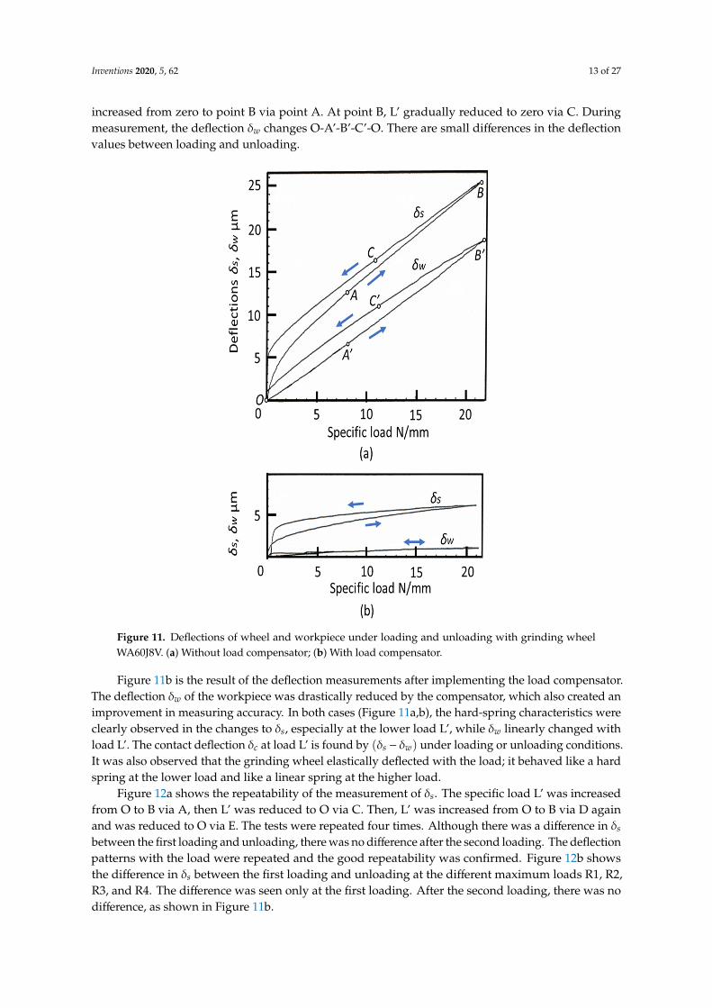
The deflections of δs and δw were directly measured under loading and unloading conditions. Thispaper names this method “deflection method”. Figure 11a shows the measurement results withoutthe load compensator. When the specific load L’ was increased from zero to 22 N/mm, deflection δs
Inventions 2020, 5, 62 13 of 27
increased from zero to point B via point A. At point B, L’ gradually reduced to zero via C. Duringmeasurement, the deflection δw changes O-A’-B’-C’-O. There are small differences in the deflectionvalues between loading and unloading.
Inventions 2020, 5, 62 13 of 29
Figure 10. Contact footprint of grinding wheel WA60J8V, 𝑑 = 195 mm, 𝑑 = 98 mm, 𝑏 = 20 mm. (a) 1 N/mm; (b) 2.5 N/mm; (c) 5 N/mm; (d) 10 N/mm.
3.3. Deflection Method
The deflections of 𝛿 and 𝛿 were directly measured under loading and unloading conditions. This paper names this method “deflection method”. Figure 11a shows the measurement results without the load compensator. When the specific load L’ was increased from zero to 22 N/mm, deflection 𝛿 increased from zero to point B via point A. At point B, L’ gradually reduced to zero via C. During measurement, the deflection 𝛿 changes O-A’-B’-C’-O. There are small differences in the deflection values between loading and unloading.
Figure 11b is the result of the deflection measurements after implementing the load compensator. The deflection 𝛿 of the workpiece was drastically reduced by the compensator, which also created an improvement in measuring accuracy. In both cases (Figure 11a,b), the hard-spring characteristics were clearly observed in the changes to 𝛿 , especially at the lower load L’, while 𝛿 linearly changed with load L’. The contact deflection 𝛿 at load L’ is found by (𝛿 − 𝛿 ) under loading or unloading conditions. It was also observed that the grinding wheel elastically deflected with the load; it behaved like a hard spring at the lower load and like a linear spring at the higher load.
Figure 11. Deflections of wheel and workpiece under loading and unloading with grinding wheel WA60J8V. (a) Without load compensator; (b) With load compensator.
Figure 12a shows the repeatability of the measurement of 𝛿 . The specific load L’ was increased from O to B via A, then L’ was reduced to O via C. Then, L’ was increased from O to B via D again and was reduced to O via E. The tests were repeated four times. Although there was a difference in 𝛿 between the first loading and unloading, there was no difference after the second loading. The
Figure 11. Deflections of wheel and workpiece under loading and unloading with grinding wheelWA60J8V. (a) Without load compensator; (b) With load compensator.
Figure 11b is the result of the deflection measurements after implementing the load compensator.The deflection δw of the workpiece was drastically reduced by the compensator, which also created animprovement in measuring accuracy. In both cases (Figure 11a,b), the hard-spring characteristics wereclearly observed in the changes to δs, especially at the lower load L’, while δw linearly changed withload L’. The contact deflection δc at load L’ is found by (δs − δw) under loading or unloading conditions.It was also observed that the grinding wheel elastically deflected with the load; it behaved like a hardspring at the lower load and like a linear spring at the higher load.
Figure 12a shows the repeatability of the measurement of δs. The specific load L’ was increasedfrom O to B via A, then L’ was reduced to O via C. Then, L’ was increased from O to B via D againand was reduced to O via E. The tests were repeated four times. Although there was a difference in δs
between the first loading and unloading, there was no difference after the second loading. The deflectionpatterns with the load were repeated and the good repeatability was confirmed. Figure 12b showsthe difference in δs between the first loading and unloading at the different maximum loads R1, R2,R3, and R4. The difference was seen only at the first loading. After the second loading, there was nodifference, as shown in Figure 11b.

Inventions 2020, 5, 62 14 of 27
Inventions 2020, 5, 62 14 of 29
deflection patterns with the load were repeated and the good repeatability was confirmed. Figure 12b shows the difference in 𝛿 between the first loading and unloading at the different maximum loads R1, R2, R3, and R4. The difference was seen only at the first loading. After the second loading, there was no difference, as shown in Figure 11b.
Figure 12. Repeatability of the measurements of wheel deflection, grinding wheel WA60J8V. (a) Same load cycle; (b) Incremental load cycle.
3.4. Modeling of Grinding Wheel Contact Deflection
Figure 13 compares the measurement results of wheel contact deflection 𝛿 obtained by the deflection method with the load compensator and the footprint method. The deflections 𝛿 found by the deflection method are greater than the footprint values at each specific load L’. Although the deflection method has much higher measurement accuracy than the footprint method, the difference is obvious. It can be considered that the footprint method’s results reflect only the deflection of the local contact area, while the deflection method’s results contain the deflections of both the local contact area and the wheel body from the contact point to the bore with wheel flange. Both methods reveal that wheel deflection is composed of non-linear characteristics at the lower range of the load and linear spring characteristics at the higher range of the load. In this case, the critical specific load is about 3 N/mm.
Figure 12. Repeatability of the measurements of wheel deflection, grinding wheel WA60J8V. (a) Sameload cycle; (b) Incremental load cycle.
3.4. Modeling of Grinding Wheel Contact Deflection
Figure 13 compares the measurement results of wheel contact deflection δc obtained by thedeflection method with the load compensator and the footprint method. The deflections δc found by thedeflection method are greater than the footprint values at each specific load L′. Although the deflectionmethod has much higher measurement accuracy than the footprint method, the difference is obvious. Itcan be considered that the footprint method’s results reflect only the deflection of the local contact area,while the deflection method’s results contain the deflections of both the local contact area and the wheelbody from the contact point to the bore with wheel flange. Both methods reveal that wheel deflection iscomposed of non-linear characteristics at the lower range of the load and linear spring characteristics atthe higher range of the load. In this case, the critical specific load is about 3 N/mm.
From the experimental observations, it is assumed that the contact stiffness of the grinding wheelis composed of a non-linear spring and a liner spring. Figure 14a illustrates the wheel-workpieceinference with the equivalent wheel diameter deq. The contact deflection δc under the normal load L isrepresented by a hard spring shown in Figure 14b. It is assumed that the hard spring can be replacedwith the series connection of two springs shown in Figure 14c. One has the non-linear spring constantka, which represents the local stiffness of the contact area. The other has the linear spring constant kb,which represents the body stiffness of the grinding wheel itself.

Inventions 2020, 5, 62 15 of 27Inventions 2020, 5, 62 15 of 29
Figure 13. Comparison of wheel deflections obtained by the deflection method and the footprint method.
From the experimental observations, it is assumed that the contact stiffness of the grinding wheel is composed of a non-linear spring and a liner spring. Figure 14a illustrates the wheel-workpiece inference with the equivalent wheel diameter 𝑑 . The contact deflection 𝛿 under the normal load L is represented by a hard spring shown in Figure 14b. It is assumed that the hard spring can be replaced with the series connection of two springs shown in Figure 14c. One has the non-linear spring constant 𝑘 , which represents the local stiffness of the contact area. The other has the linear spring constant 𝑘 , which represents the body stiffness of the grinding wheel itself.
Figure 14. Modeling of the contact stiffness of the grinding wheel. (a) Contact of wheel with workpiece; (b) Model of contact stiffness; (c) Series connection of linear and non-linear springs.
In Figure 14c, contact deflection 𝛿 is expressed by: 𝛿 = 𝛿 𝛿 (38)
where 𝛿 is the deflection of the non-linear spring with 𝑘 , and 𝛿 is the deflection of the linear spring with 𝑘 . As 𝛿 represents the non-linear deflection with load L, it is assumed that deflection 𝛿 can be represented by: 𝛿 = 𝐴(1 − 𝑒 ) (39)
Figure 13. Comparison of wheel deflections obtained by the deflection method and the footprint method.
Inventions 2020, 5, 62 15 of 29
Figure 13. Comparison of wheel deflections obtained by the deflection method and the footprint method.
From the experimental observations, it is assumed that the contact stiffness of the grinding wheel is composed of a non-linear spring and a liner spring. Figure 14a illustrates the wheel-workpiece inference with the equivalent wheel diameter 𝑑 . The contact deflection 𝛿 under the normal load L is represented by a hard spring shown in Figure 14b. It is assumed that the hard spring can be replaced with the series connection of two springs shown in Figure 14c. One has the non-linear spring constant 𝑘 , which represents the local stiffness of the contact area. The other has the linear spring constant 𝑘 , which represents the body stiffness of the grinding wheel itself.
Figure 14. Modeling of the contact stiffness of the grinding wheel. (a) Contact of wheel with workpiece; (b) Model of contact stiffness; (c) Series connection of linear and non-linear springs.
In Figure 14c, contact deflection 𝛿 is expressed by: 𝛿 = 𝛿 𝛿 (38)
where 𝛿 is the deflection of the non-linear spring with 𝑘 , and 𝛿 is the deflection of the linear spring with 𝑘 . As 𝛿 represents the non-linear deflection with load L, it is assumed that deflection 𝛿 can be represented by: 𝛿 = 𝐴(1 − 𝑒 ) (39)
Figure 14. Modeling of the contact stiffness of the grinding wheel. (a) Contact of wheel with workpiece;(b) Model of contact stiffness; (c) Series connection of linear and non-linear springs.
In Figure 14c, contact deflection δc is expressed by:
δc = δa + δb (38)
where δa is the deflection of the non-linear spring with ka, and δb is the deflection of the linear springwith kb. As δa represents the non-linear deflection with load L, it is assumed that deflection δa can berepresented by:
δa = A(1− e−
L′S
)(39)
where A and S are constants and L′ is the specific load per unit contact width. It is also assumed thatthe body of the grinding wheel has a spring constant of kb. So, deflection δb is expressed by:
δb =L′
kb′
(40)
where kb′ is the specific spring stiffness per unit width. Therefore, contact deflection δc can be rewritten
as follows:δc = A
(1− e−
L′S
)+
L′
kb′. (41)

Inventions 2020, 5, 62 16 of 27
Differentiating both sides of Equation (41) provides the specific compliance dδc/dL′ of the grindingwheel.
dδc
dL′=
AS
e−L′S +
1kb′. (42)
Therefore, specific contact stiffness kc′ per unit width can be expressed by:
kc′ = 1/
[AS
e−L′S +
1kb′
]. (43)
Also, the non-linear contact stiffness of local area per unit width ka′ is:
ka′ =
SA
eL′S . (44)
In Figure 13, the best fit curves for both methods were found by using Equation (41). The solidline is for the deflection method and the dotted line is for the footprint method. The parameters shownin Table 3 were used for the calculations of δc. kb
′ represents the wheel body stiffness and parameter Ashows the degree of local deflection δa. Parameter S expresses the degree of raising curve at the lowerspecific load L′.
Table 3. Parameters for representing the contact deflection of the grinding wheel WA60J8V.
Parameter Unit Deflection Method Footprint Method
kb′ kN/mm·mm 3.5 3.5
A µm 2.3 0.8
S N/mm 1.1 1.1
The specific contact stiffnesses for both methods were calculated by using Equation (43), as shownin Figure 15. At L′ > 6 N/mm·mm, both methods provide the same contact stiffness. At L′ < 6 N/
mm·mm, the deflection method provides lower contact stiffness than the footprint method. The specificcontact stiffness kc
′ was 3.5 kN/mm·mm at L′ > 6 kN/mm. At L′ = 2 kN/mm, 1.5 kN/mm·mm and2.5 kN/mm·mm were obtained by the deflection method and the footprint method, respectively.
Inventions 2020, 5, 62 16 of 29
where A and S are constants and 𝐿 is the specific load per unit contact width. It is also assumed that the body of the grinding wheel has a spring constant of 𝑘 . So, deflection 𝛿 is expressed by: 𝛿 = 𝐿𝑘 (40)
where 𝑘 is the specific spring stiffness per unit width. Therefore, contact deflection 𝛿 can be rewritten as follows: 𝛿 = 𝐴 1 − 𝑒 . (41)
Differentiating both sides of Equation (41) provides the specific compliance 𝑑𝛿 𝑑𝐿⁄ of the grinding wheel. = 𝑒 . (42)
Therefore, specific contact stiffness 𝑘 per unit width can be expressed by: 𝑘 = 1 𝐴𝑆 𝑒 1𝑘 . (43)
Also, the non-linear contact stiffness of local area per unit width 𝑘 is: 𝑘 = 𝑆𝐴 𝑒 . (44)
In Figure 13, the best fit curves for both methods were found by using Equation (41). The solid line is for the deflection method and the dotted line is for the footprint method. The parameters shown in Table 3 were used for the calculations of 𝛿 . 𝑘 represents the wheel body stiffness and parameter A shows the degree of local deflection 𝛿 . Parameter S expresses the degree of raising curve at the lower specific load L’.
The specific contact stiffnesses for both methods were calculated by using Equation (43), as shown in Figure 15. At L’ > 6 N/mm·mm, both methods provide the same contact stiffness. At L’< 6 N/ mm·mm, the deflection method provides lower contact stiffness than the footprint method. The specific contact stiffness 𝑘 was 3.5 kN/mm·mm at L’ > 6 kN/mm. At L’ = 2 kN/mm, 1.5 kN/mm·mm and 2.5 kN/mm·mm were obtained by the deflection method and the footprint method, respectively.
Figure 15. Specific contact stiffness of grinding wheel.
Based on the contact stiffness model, the specific contact stiffness 𝑘 is composed of two components, 𝑘 for local deflection and 𝑘 for wheel body deflection. Figure 16 shows the specific
Figure 15. Specific contact stiffness of grinding wheel.
Based on the contact stiffness model, the specific contact stiffness kc′ is composed of two
components, ka′ for local deflection and kb
′ for wheel body deflection. Figure 16 shows the specific

Inventions 2020, 5, 62 17 of 27
contact stiffness kc′ obtained by the deflection method, where ka
′ was found by Equation (44) and kb′
was set to 3.5 kN/mm·mm. The specific local area stiffness ka′ shows heavy hard-spring characteristics
such as lower stiffness at L′ < 2 kN/mm and higher stiffness at L′ > 3 kN/mm. The dominant componentof kc
′ is ka′ at the lower load L′ < 2 kN/mm and kb
′ at the higher load L′ > 4 kN/mm.
Inventions 2020, 5, 62 17 of 29
contact stiffness 𝑘 obtained by the deflection method, where 𝑘 was found by Equation (44) and 𝑘 was set to 3.5 kN/mm·mm. The specific local area stiffness 𝑘 shows heavy hard-spring characteristics such as lower stiffness at L’< 2 kN/mm and higher stiffness at L’> 3 kN/mm. The dominant component of 𝑘 is 𝑘 at the lower load L’< 2 kN/mm and 𝑘 at the higher load L’> 4 kN/mm.
Table 3. Parameters for representing the contact deflection of the grinding wheel WA60J8V.
Parameter Unit Deflection Method Footprint Method 𝑘 kN/mm·mm 3.5 3.5 A μm 2.3 0.8 S N/mm 1.1 1.1
Figure 16. Components of specific contact stiffness.
3.5. Measurement Results of Grinding Wheel Contact Stiffness
The contact deflections 𝛿 of four kinds of grinding wheels shown in Table 2 were measured by the deflection method with the load compensator. Figure 17 shows the measurement results. The best fit curves were found by using the parameters shown in Table 4. As seen in Figure 17, all grinding wheels exhibited heavy hard-spring behavior at the lower load and a liner spring nature at the higher load. The resinoid bond wheel WA60L8B exhibited the greatest deflection among the tested wheels and the vitrified bond wheel WA60L8V gave the smallest. In wheels WA60M8V and WA60L8B, the reduction of the deflection appeared at L’> 8 kN/mm. It seems that a structural change in the grinding wheels occurred at the higher load. These phenomena should be investigated in the future.
Figure 16. Components of specific contact stiffness.
3.5. Measurement Results of Grinding Wheel Contact Stiffness
The contact deflections δc of four kinds of grinding wheels shown in Table 2 were measured bythe deflection method with the load compensator. Figure 17 shows the measurement results. The bestfit curves were found by using the parameters shown in Table 4. As seen in Figure 17, all grindingwheels exhibited heavy hard-spring behavior at the lower load and a liner spring nature at the higherload. The resinoid bond wheel WA60L8B exhibited the greatest deflection among the tested wheelsand the vitrified bond wheel WA60L8V gave the smallest. In wheels WA60M8V and WA60L8B, thereduction of the deflection appeared at L’> 8 kN/mm. It seems that a structural change in the grindingwheels occurred at the higher load. These phenomena should be investigated in the future.Inventions 2020, 5, 62 18 of 29
Figure 17. Contact deflection of various Al O #60 grinding wheels.
The contact stiffnesses were found by Equation (43) from the deflection curves shown in Figure 17. Figure 18 shows the specific contact stiffness 𝑘 of various 𝐴𝑙 𝑂 #60 grinding wheels. The WA60L8V wheel had the highest contact stiffness, followed by the WA60J8V and WA60M8V wheels. The resinoid bond WA60J8B wheel had the lowest stiffness among them. At the specific load L’ < 2 kN/mm, all grinding wheels exhibited very low contact stiffness at the range of 0 < L’< 4 N/mm. At the higher load L’> 4 N/mm, the contact stiffness reached a constant level.
Figure 18. Contact stiffness of various Al O #60 grinding wheels.
Table 4. Parameters of various grinding wheels obtained by the deflection measurements.
Parameter Unit WA60J8V WA60L8V WA60M8V WA60L8B 𝑘 kN/mm·mm 7.7 9.1 4.5 3.6 A Μm 1 0.5 1.8 2.6 S N/mm 1.2 1.2 0.7 0.7
Figure 17. Contact deflection of various Al2O3#60 grinding wheels.

Inventions 2020, 5, 62 18 of 27
Table 4. Parameters of various grinding wheels obtained by the deflection measurements.
Parameter Unit WA60J8V WA60L8V WA60M8V WA60L8B
kb′ kN/mm·mm 7.7 9.1 4.5 3.6
A Mm 1 0.5 1.8 2.6
S N/mm 1.2 1.2 0.7 0.7
The contact stiffnesses were found by Equation (43) from the deflection curves shown in Figure 17.Figure 18 shows the specific contact stiffness kc
′ of various Al2O3#60 grinding wheels. The WA60L8Vwheel had the highest contact stiffness, followed by the WA60J8V and WA60M8V wheels. The resinoidbond WA60J8B wheel had the lowest stiffness among them. At the specific load L′ < 2 kN/mm, allgrinding wheels exhibited very low contact stiffness at the range of 0 < L′ < 4 N/mm. At the higherload L′ > 4 N/mm, the contact stiffness reached a constant level.
Inventions 2020, 5, 62 18 of 29
Figure 17. Contact deflection of various Al O #60 grinding wheels.
The contact stiffnesses were found by Equation (43) from the deflection curves shown in Figure 17. Figure 18 shows the specific contact stiffness 𝑘 of various 𝐴𝑙 𝑂 #60 grinding wheels. The WA60L8V wheel had the highest contact stiffness, followed by the WA60J8V and WA60M8V wheels. The resinoid bond WA60J8B wheel had the lowest stiffness among them. At the specific load L’ < 2 kN/mm, all grinding wheels exhibited very low contact stiffness at the range of 0 < L’< 4 N/mm. At the higher load L’> 4 N/mm, the contact stiffness reached a constant level.
Figure 18. Contact stiffness of various Al O #60 grinding wheels.
Table 4. Parameters of various grinding wheels obtained by the deflection measurements.
Parameter Unit WA60J8V WA60L8V WA60M8V WA60L8B 𝑘 kN/mm·mm 7.7 9.1 4.5 3.6 A Μm 1 0.5 1.8 2.6 S N/mm 1.2 1.2 0.7 0.7
Figure 18. Contact stiffness of various Al2O3 #60 grinding wheels.
Figure 19 shows the influence of accumulative SMR (specific material removal) on the deflectionof the WA60M8V wheel. The dressing conditions are single point dresser, dressing lead 0.1 mm/rev.,and adress depth of cut 20 µm. The best fit curves are drawn in the figure. The deflection after dressingwas reduced and the deflection curve changed with increased SMR. No clear trend was observed.After dressing, the deflection curves gradually changed up and down according to the accumulativeSMR progression. The G-ratio (grinding ratio) for monitoring the wear progress was not investigatedin this study.
Figure 20 shows the changes in contact stiffness after dressing. The contact stiffness was found byapplying the parameters shown in Table 5 to Equation (43). The contact stiffness at the lower range ofload (L′ < 1.5 kN/mm) was very low and no corresponding change occurred. But, at the higher range(L′ > 4 kN/mm), the contact stiffness increased significantly by 20–50% after dressing.
Table 5. Parameters of wheel deflection taken during specific material removal (SMR) progression.
Item Unit Obtained Parameter
SMR mm3/mm 0 8 160 320 700
kb′ kN/mm·mm 5.9 9.1 6.7 10 12.5
A µm 1.9 1.4 1.6 1.4 1.3
S N/mm 0.5 0.5 0.5 0.5 0.5

Inventions 2020, 5, 62 19 of 27
Inventions 2020, 5, 62 19 of 29
Figure 19 shows the influence of accumulative SMR (specific material removal) on the deflection of the WA60M8V wheel. The dressing conditions are single point dresser, dressing lead 0.1 mm/rev., and adress depth of cut 20 μm. The best fit curves are drawn in the figure. The deflection after dressing was reduced and the deflection curve changed with increased SMR. No clear trend was observed. After dressing, the deflection curves gradually changed up and down according to the accumulative SMR progression. The G-ratio (grinding ratio) for monitoring the wear progress was not investigated in this study.
Figure 19. The effect of accumulative specific material removal on contact deflection.
Figure 20 shows the changes in contact stiffness after dressing. The contact stiffness was found by applying the parameters shown in Table 5 to Equation (43). The contact stiffness at the lower range of load (L’< 1.5 kN/mm) was very low and no corresponding change occurred. But, at the higher range (L’> 4 kN/mm), the contact stiffness increased significantly by 20–50% after dressing.
Figure 20. The effect of accumulative specific material removal on contact stiffness.
Figure 19. The effect of accumulative specific material removal on contact deflection.
Inventions 2020, 5, 62 19 of 29
Figure 19 shows the influence of accumulative SMR (specific material removal) on the deflection of the WA60M8V wheel. The dressing conditions are single point dresser, dressing lead 0.1 mm/rev., and adress depth of cut 20 μm. The best fit curves are drawn in the figure. The deflection after dressing was reduced and the deflection curve changed with increased SMR. No clear trend was observed. After dressing, the deflection curves gradually changed up and down according to the accumulative SMR progression. The G-ratio (grinding ratio) for monitoring the wear progress was not investigated in this study.
Figure 19. The effect of accumulative specific material removal on contact deflection.
Figure 20 shows the changes in contact stiffness after dressing. The contact stiffness was found by applying the parameters shown in Table 5 to Equation (43). The contact stiffness at the lower range of load (L’< 1.5 kN/mm) was very low and no corresponding change occurred. But, at the higher range (L’> 4 kN/mm), the contact stiffness increased significantly by 20–50% after dressing.
Figure 20. The effect of accumulative specific material removal on contact stiffness.
Figure 20. The effect of accumulative specific material removal on contact stiffness.
4. Results of Plunge Cylindrical and Centerless Grinding Tests
4.1. Test Results of Plunge Cylindrical Grinding
Given that the contact stiffness kc of the grinding wheel largely relies on the specific normal loadL′, it is expected that the normal grinding force Fn affects the time constant T in the plunge grindingsystem because T is a function of kc (see Equation (34)). Plunge cylindrical grinding (c = 1.0) tests werecarried out with various infeed rates fi, and grinding power Pg was measured during the grindingprocess. The grinding conditions are shown in Table 6.
Figure 21 shows the ramping up of the grinding power from start to steady state during theplunge grinding process. At SMRR Qw
′ = 0.25 mm3/mm·s, which was very low (Figure 21a), thegrinding power slowly built up and finally reached a steady state power of 0.31 kW. From the powercurve, the time constant T of 17 s was measured. The time constant became shorter with increasedSMRR Qw
′. At Qw′ = 2.0 mm3/mm·s, the time constant T was shortened and T = 8.2 s was obtained.
The reason the time constant gets shorter with increased Qw′ is that contact stiffness kc becomes
greater at the higher normal grinding force Fn. The estimated range of the specific normal grindingforce Fn
′ is 0.46~2.36 N/mm, which can be considered as the lower specific load L′. In the load range,contact stiffness kc clearly exhibits a hard-spring nature and the contact time constant Tc of Equation (34)significantly changes.

Inventions 2020, 5, 62 20 of 27
Table 6. Grinding conditions of plunge cylindrical grinding.
Item Conditions
Grinding machine Universal cylindrical grinder: Heald 2EF Cinternal
Grinding method Chuck type cylindrical grinding
WorkpieceMaterial: Through-hardened 52100 (HRC58)Diameter: 177.8 mmWidth: 30 mm
Grinding wheelSpecification: A70KmVDiameter: 127 mmWidth: 86.4 mm
Grinding speed, ratio Grinding speed: 45 m/s, Speed ratio: 1/100Inventions 2020, 5, 62 21 of 29
Figure 21. Experimental results of plunge cylindrical grinding and the time constant. (a) 𝑄 = 0.25 mm³/mm·s; (b) 𝑄 = 0.5 mm³/mm·s; (c) 𝑄 = 1.0 mm³/mm·s; (d) 𝑄 = 2.0 mm³/mm·s.
4.2. Test Results of Plunge Centerless Grinding
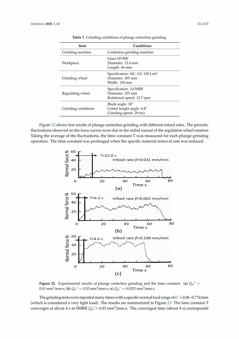
Table 7 delineates the grinding conditions for plunge centerless grinding (c = 0.5) of glass workpieces. The regulating wheel spindle of the grinding machine was supported by hydrostatic bearings and the grinding forces were measured by detecting the pocket pressures of the bearings [29].
Table 7. Grinding conditions of plunge centerless grinding.
Item Conditions Grinding machine Centerless grinding machine
Workpiece Glass HV500 Diameter: 12.4 mm Length: 66 mm
Grinding wheel Specification: SiC, GC 100 LmV Diameter: 455 mm Width: 150 mm
Regulating wheel Specification: A150RR
Figure 21. Experimental results of plunge cylindrical grinding and the time constant. (a) Qw′ =
0.25 mm3/mm·s; (b) Qw′ = 0.5 mm3/mm·s; (c) Qw
′ = 1.0 mm3/mm·s; (d) Qw′ = 2.0 mm3/mm·s.
4.2. Test Results of Plunge Centerless Grinding
Table 7 delineates the grinding conditions for plunge centerless grinding (c = 0.5) of glassworkpieces. The regulating wheel spindle of the grinding machine was supported by hydrostaticbearings and the grinding forces were measured by detecting the pocket pressures of the bearings [29].
Inventions 2020, 5, 62 21 of 27
Table 7. Grinding conditions of plunge centerless grinding.
Item Conditions
Grinding machine Centerless grinding machine
WorkpieceGlass HV500Diameter: 12.4 mmLength: 66 mm
Grinding wheelSpecification: SiC, GC 100 LmVDiameter: 455 mmWidth: 150 mm
Regulating wheelSpecification: A150RRDiameter: 255 mmRotational speed: 12.7 rpm
Grinding conditionsBlade angle: 30◦
Center height angle: 6.8◦
Grinding speed: 29 m/s
Figure 22 shows test results of plunge centerless grinding with different infeed rates. The periodicfluctuations observed on the force curves were due to the radial runout of the regulation wheel rotation.Taking the average of the fluctuations, the time constant T was measured for each plunge grindingoperation. The time constant was prolonged when the specific material removal rate was reduced.
Inventions 2020, 5, 62 22 of 29
Diameter: 255 mm Rotational speed: 12.7 rpm
Grinding conditions Blade angle: 30° Center height angle: 6.8° Grinding speed: 29 m/s
Figure 22 shows test results of plunge centerless grinding with different infeed rates. The periodic fluctuations observed on the force curves were due to the radial runout of the regulation wheel rotation. Taking the average of the fluctuations, the time constant T was measured for each plunge grinding operation. The time constant was prolonged when the specific material removal rate was reduced.
Figure 22. Experimental results of plunge centerless grinding and the time constant. (a) 𝑄 = 0.01 mm³/mm·s; (b) 𝑄 = 0.02 mm³/mm·s; (c) 𝑄 = 0.0325 mm³/mm·s.
The grinding tests were repeated many times with a specific normal load range of 𝐿 = 0.06~0.7 N/mm (which is considered a very light load). The results are summarized in Figure 23. The time constant T converges at about 4 s at SMRR 𝑄 > 0.03 mm³/mm·s. The converged time (about 4 s) corresponds to the machine time constant 𝑇 described in Figure 7. By contrast, the time constant was rapidly prolonged where the SMRR was reduced. It reaches 28 s at SMRR 𝑄 = 0.002 mm³/mm·s. In this case, the contact time constant 𝑇 becomes 24 s. The increased 𝑇 comes from the reduced contact stiffness created by the reduced contact load. This result clearly reveals that the time constant T is significantly increased with reduced SMRR 𝑄 .
Figure 22. Experimental results of plunge centerless grinding and the time constant. (a) Qw′ =
0.01 mm3/mm·s; (b) Qw′ = 0.02 mm3/mm·s; (c) Qw
′ = 0.0325 mm3/mm·s.
The grinding tests were repeated many times with a specific normal load range of L′ = 0.06~0.7 N/mm(which is considered a very light load). The results are summarized in Figure 23. The time constant Tconverges at about 4 s at SMRR Qw
′> 0.03 mm3/mm·s. The converged time (about 4 s) corresponds

Inventions 2020, 5, 62 22 of 27
to the machine time constant Tm described in Figure 7. By contrast, the time constant was rapidlyprolonged where the SMRR was reduced. It reaches 28 s at SMRR Qw
′= 0.002 mm3/mm·s. In this case,the contact time constant Tc becomes 24 s. The increased Tc comes from the reduced contact stiffnesscreated by the reduced contact load. This result clearly reveals that the time constant T is significantlyincreased with reduced SMRR Qw
′.Inventions 2020, 5, 62 23 of 29
Figure 23. The effect of specific material removal rate on the time constant in plunge centerless grinding.
5. Validation and Discussion
The plunge cylindrical grinding (c = 1.0) test results shown in Figure 21a–d were simulated using Equations (19)–(28) for the primary grinding cycle shown in Figure 4b. The simulation results are shown in Figure 24a–d. Also, Figure 25a–c show the simulations of experimental results obtained by plunge centerless grinding (c = 0.5) shown in Figure 22a–c. In all simulations of plunge grinding operations, the transient behaviors in build-up during ramp infeed and the reduction during spark-out are almost identical to the experimental results, and the levels in steady state and the time constant are excellent matches to the experimental results. These correlations indicate that the proposed model can accurately predict critical parameters such as forces 𝐹 and 𝐹 , power 𝑃 , machine deflection de, equivalent system stiffness keq, and time constant T during both plunge cylindrical grinding and centerless grinding.
Figure 23. The effect of specific material removal rate on the time constant in plunge centerless grinding.
5. Validation and Discussion
The plunge cylindrical grinding (c = 1.0) test results shown in Figure 21a–d were simulated usingEquations (19)–(28) for the primary grinding cycle shown in Figure 4b. The simulation results areshown in Figure 24a–d. Also, Figure 25a–c show the simulations of experimental results obtainedby plunge centerless grinding (c = 0.5) shown in Figure 22a–c. In all simulations of plunge grindingoperations, the transient behaviors in build-up during ramp infeed and the reduction during spark-outare almost identical to the experimental results, and the levels in steady state and the time constant areexcellent matches to the experimental results. These correlations indicate that the proposed modelcan accurately predict critical parameters such as forces Ft and Fn, power Pg, machine deflection de,equivalent system stiffness keq, and time constant T during both plunge cylindrical grinding andcenterless grinding.
Table 8 lists the critical parameters obtained by the simulations in Figure 24a–d. The specificenergy u for each plunge grinding operation was found, and it was observed that u increased withincreased SMRR Qw
′. These phenomena are well known in grinding [30]. The equivalent chip thicknessheq (defined as the ratio of SMRR Qw
′ to grinding speed vs) is a key parameter that affects energy u andthe finished surface quality [31]. The system stiffness keq obtained by the simulation decreased withthe decrease in specific normal grinding force Fn
′.
Table 8. Critical parameters obtained by the simulations in Figure 23.
Symbol Fn′ u T keq k̂m kc
′
Unit N/mm J/mm3 s kN/mm kN/mm kN/mm·mm
(a) 0.46 41.4 16 1.92 2.47 0.29
(b) 0.83 37.4 14 1.99 2.47 0.34
(c) 1.36 30.7 10.7 2.13 2.47 0.52
(d) 2.36 26.7 8.2 2.42 2.47 4.0
Fn′: specific normal grinding force, u: specific energy, T: time constant, keq: system stiffness, ˆkm: estimated machine
stiffness, kc′: specific contact stiffness.

Inventions 2020, 5, 62 23 of 27
From the system stiffness analysis, the machine stiffness of the applied grinder was estimated tok̂m = 2.47 kN/mm as a constant value. Then, the specific contact stiffness kc
′ of the grinding wheel wascalculated. kc
′ = 4.0 kN/mm·mm was obtained when the infeed rate was highest (Figure 24d). Whenthe infeed rate was slowest (Figure 24a), the specific contact stiffness was significantly reduced to kc
′ =
0.29 kN/mm·mm and hard-spring characteristics were clearly exhibited, as expected.As the result of the reduced system stiffness keq due to the reduction of contact stiffness kc, the
time constant T drastically increased by over 200% from 8.2 s to 17 s, as predicted by Equation (10). So,when a grinding cycle is designed, the plunge infeed time and spark-out time should be determinedby taking into account the influence of the infeed rate on the time constant T.
It is clear that the time constant T significantly changes by 2–2.6 times, as seen in Figures 24and 25. The amount of change depends on the contact stiffness of the grinding wheel, which relies oncontact load L; that is, normal grinding force Fn in this case. When a plunge grinding cycle with alower infeed rate fi is set up, a long-time constant will be found due to the lower contact stiffness at thelower grinding force Fn. On the other hand, the effect of contact stiffness on the time constant can beignored when high stock removal conditions with high SMRR Qw
′ and high normal grinding force Fn
are set up.Inventions 2020, 5, 62 24 of 29
Figure 24. Simulations of plunge cylindrical grinding processes. (a) 𝑄 = 0.25 mm³/mm·s; (b) 𝑄 = 0.5 mm³/mm·s; (c) 𝑄 = 1.0 mm³/mm·s; (d) 𝑄 = 2.0 mm³/mm·s.
Figure 24. Simulations of plunge cylindrical grinding processes. (a) Qw′ = 0.25 mm3/mm·s; (b) Qw
′ =
0.5 mm3/mm·s; (c) Qw′ = 1.0 mm3/mm·s; (d) Qw
′ = 2.0 mm3/mm·s.

Inventions 2020, 5, 62 24 of 27Inventions 2020, 5, 62 25 of 29
Figure 25. Simulations of plunge centerless grinding. (a) 𝑄 = 0.01 mm³/mm·s; (b) 𝑄 = 0.02 mm³/mm·s; (c) 𝑄 = 0.0325 mm³/mm·s.
Table 8 lists the critical parameters obtained by the simulations in Figure 24a–d. The specific energy u for each plunge grinding operation was found, and it was observed that u increased with increased SMRR 𝑄 . These phenomena are well known in grinding [30]. The equivalent chip thickness ℎ (defined as the ratio of SMRR 𝑄 to grinding speed 𝑣 ) is a key parameter that affects energy u and the finished surface quality [31]. The system stiffness 𝑘 obtained by the simulation decreased with the decrease in specific normal grinding force 𝐹 .
From the system stiffness analysis, the machine stiffness of the applied grinder was estimated to 𝑘 = 2.47 kN/mm as a constant value. Then, the specific contact stiffness 𝑘 of the grinding wheel was calculated. 𝑘 = 4.0 kN/mm·mm was obtained when the infeed rate was highest (Figure 24d). When the infeed rate was slowest (Figure 24a), the specific contact stiffness was significantly reduced to 𝑘 = 0.29 kN/mm·mm and hard-spring characteristics were clearly exhibited, as expected.
As the result of the reduced system stiffness 𝑘 due to the reduction of contact stiffness 𝑘 , the time constant T drastically increased by over 200% from 8.2 s to 17 s, as predicted by Equation (10). So, when a grinding cycle is designed, the plunge infeed time and spark-out time should be determined by taking into account the influence of the infeed rate on the time constant T.
It is clear that the time constant T significantly changes by 2–2.6 times, as seen in Figures 24 and 25. The amount of change depends on the contact stiffness of the grinding wheel, which relies on contact load L; that is, normal grinding force 𝐹 in this case. When a plunge grinding cycle with a lower infeed rate fi is set up, a long-time constant will be found due to the lower contact stiffness at the lower grinding force Fn. On the other hand, the effect of contact stiffness on the time constant can
Figure 25. Simulations of plunge centerless grinding. (a) Qw′ = 0.01 mm3/mm·s; (b) Qw
′ =
0.02 mm3/mm·s; (c) Qw′ = 0.0325 mm3/mm·s.
In general, the ramp infeed time of the plunge grinding cycle requires at least five times T(5T). This setting provides sufficient time for reaching 99.3% of the target level of the steady state((1− e−5
)= 0.993). The spark-out time requires at least three times T (3T) in order to reduce the system
deflection de by 95% ((1− e−3
)= 0.950). Setting the spark-out time to 3T affords the grinding operation
not only improved size error, but also improved roundness of the finished products. In the plungegrinding operations using Al2O3 grinding wheels, the time constant T can be reasonably estimated byusing the data of wheel contact stiffness shown in Figures 18 and 20. It allows process engineers todetermine the spark-out time and the proper grinding cycle for achieving the required size error androundness. The design procedures are described in [27].
For high-efficiency and high-precision plunge grinding, it is vital to take the effect of contactstiffness on the plunge grinding process into consideration during the design of the grinding cycle.

Inventions 2020, 5, 62 25 of 27
6. Conclusions
This paper presented the effect of grinding wheel contact stiffness on the plunge grinding cycleand provided guidelines for the design of the grinding cycle. First, the generalized plunge grindingsystem (including cylindrical, centerless, shoe-centerless, internal, and shoe-internal grinding) wasexplicitly described and analyzed in terms of system outputs corresponding to the inputs of the plungegrinding conditions. The analysis discussed the influence of system stiffness on the time constant thatgoverns the transient behaviors of process parameters such as forces, power, and machine deflection.Also, it clarified that system stiffness is composed of machine stiffness and wheel contact stiffness,and these stiffnesses significantly affect grinding performance indicators such as productivity andgrinding accuracy.
The elastic deflection of the grinding wheel was accurately measured and a function for representingthe deflection nature under various contact loads was derived. The function provides the non-linearcontact stiffness with respect to the normal load. The contact stiffnesses of four kinds of grindingwheels with different grades and bond materials were presented, and changes in the contact stiffnessafter dressing were discussed.
Experimental tests for both cylindrical grinding and centerless grinding were carried out, andit was experimentally confirmed that the time constant at ramp infeed and spark-out is significantlyprolonged by reducing the grinding force. It was verified that a simulation of the grinding tests usingthe proposed model can accurately predict critical parameters like forces, machine deflection, andsystem stiffness during plunge operations. Finally, this paper emphasized that it is vital to take theeffect of wheel contact stiffness into consideration during the design of the plunge grinding cycle.
The study provides the following conclusions.
(1) The equivalent stiffness of the plunge grinding system is composed of machine stiffness andwheel contact stiffness. The contact stiffness greatly depends on the normal contact load. It isconfirmed by the measurement of wheel deflection and the plunge grinding tests with variousinfeed rates.
(2) The contact deflection of the grinding wheel behaves like a non-linear spring representing a localcontact deflection at lower load and a linear spring expressing the elasticity of the wheel bodyitself at a higher load. Formulas representing the wheel deflection behaviors are presented.
(3) The contact stiffness significantly affects the time constant T that governs the transient behaviorsin ramp infeed and spark-out grinding.
(4) The time constant T is drastically prolonged with reduced normal grinding force due to thereduction of contact stiffness at lower contact loads. The grinding tests revealed that the timeconstant T significantly changes by 2–2.6 times.
(5) All measured Al2O3 wheels exhibit very low contact stiffness at a specific load less than 3 N/mm.At a higher load greater than 4 N/mm, contact stiffness reaches a constant.
(6) Plunge grinding tests applying both cylindrical grinding and centerless grinding methods withvarious infeed rates experimentally verified the effect of wheel contact stiffness on the timeconstant T.
(7) As guidelines for plunge grinding cycle, the ramp infeed grinding time should be set to at leastfive times T and at least three times T for spark-out grinding.
Author Contributions: Conceptualization, F.H.; methodology, F.H. and H.I.; software, F.H.; validation, F.H. andH.I.; formal analysis, F.H.; investigation, F.H.; resources, F.H. and H.I.; data curation, F.H. and H.I.; writing—originaldraft preparation, F.H.; writing—review and editing, F.H. and H.I.; visualization, F.H. and H.I.; supervision, F.H.;project administration, F.H.; funding acquisition, F.H. All authors have read and agreed to the published versionof the manuscript.
Funding: This research received no external funding.

Inventions 2020, 5, 62 26 of 27
Conflicts of Interest: The authors declare no conflict of interest. F.H. is a founder of Advanced FinishingTechnology Ltd., in which he holds shares. H.I. is a founder of Toba Engineering, in which he holds shares. Thesponsors of both companies had no role in the design, collection, analysis, or interpretation of data, the writing ofthis article, or the decision to submit it for publication.
Nomenclature
s Laplace operator deq Equivalent wheel diameterDe(s) Deflection of machine in s-domain ds Diameter of grinding wheelFi(s) Actual infeed rate in s-domain dw Diameter of workpieceFn(s) Normal grinding force in s-domain fc Cut-off frequencyG(s) Transfer function in s-domain fi Actual infeed rateI f (s) Command infeed in s-domain heq Equivalent chip thicknessQw(s) MRR in s-domain ka Stiffness of wheel contact areaQw′(s) SMRR in s-domain ka
′ Specific stiffness of wheel contact areaRw(s) Actual infeed in s-domain kb Stiffness of wheel bodyA Constant kb
′ Specific stiffness of wheel bodyF Ratio of Fn to fi kc Contact stiffness of grinding wheelFn Normal grinding force kc
′ Specific contact stiffness of grinding wheelFt Tangential grinding force keq Equivalent system stiffnessFn′ Specific normal grinding force km Machine stiffness of grinding system
Ft′ Specific tangential grinding force kmi Stiffness of i-th. mechanical structureGW Grinding wheel ˆkm Estimated machine stiffnessI f Command infeed ks Stiffness of wheel support systemIp Constant infeed rate kw Stiffness of work support systemL Contact load kw0 Stiffness of workpiece itselfL′ Specific contact load lc Contact lengthMRR Material removal rate n Degrees of freedomPg Grinding power rw Actual infeedQw Material removal rate t TimeQw′ Specific material removal rate tp Plunge grinding time
RW Regulating wheel ts Time at end of grindingS Constant u Specific energySMR Specific material removal vs Grinding speedSMRR Specific material removal rate δ DeflectionT Time constant δa Deflection of wheel contact areaTc Contact time constant δb Deflection of grinding wheel bodyTm Machine time constant δc Contact deflection of grinding wheelWP Workpiece δs Deflection at flange of grinding wheelb Width of workpiece δw Deflection of workpiecec Grinding method parameter η Force ratio (Fn/Ft)de Deflection of grinding machine
References
1. Hahn, R.S. The Effect of Wheel-Work Conformity in Precision Grinding. Trans. ASME 1955, 77, 1325–1329.2. Peklenik, J. Ermittlung von Geometrschen und Physikalischen Kenngröβenfür die Grundlagenforschung
des Schleifens. Ph.D. Dissertation, Aachen Technical University, Aachen, Germany, 1957.3. Snoeys, R.; Wang, I.-C. Analysis of the Static and Dynamic Stiffness of the Grinding Surface. In Proceedings
of the 9th International MTDR Conference, Manchester, UK; 1968; p. 1133.4. Brown, R.H.; Saito, K.; Shaw, M.C. Local Elastic Deflections in Grinding. CIRP Ann. 1970, 19, 105–113.5. Kumar, K.V.; Shaw, M.C. The Role of Wheel-Work Deflection in Grinding Operations. J. Eng. Ind. 1981, 103,
73–78. [CrossRef]6. Krug, H.; Honcia, G. Die Elastische Verformung bei Schleifwerkzeugen. Werkstattstech 1964, 54, 53.7. Nakayama, K.; Brecker, J.; Shaw, M.C. Grinding Wheel Elasticity. J. Eng. Ind. 1971, 93, 609–613. [CrossRef]8. Nakayama, K. Elastic Deformation of Contact Zone in Grinding. Bull. Jpn. Soc. Prec. Eng. 1971, 5, 93.
Inventions 2020, 5, 62 27 of 27
9. Zhou, Z.; Van Lutterwelt, C. The Real Contact Length between Grinding Wheel and Workpiece—A NewConcept and a New Measuring Method. CIRP Ann. 1992, 41, 387–391. [CrossRef]
10. Rowe, W.B.; Morgan, M.N.; Qi, H.S.; Zheng, H.W. The Effect of Deformation on the Contact Area in Grinding.CIRP Ann. 1993, 42, 409–412. [CrossRef]
11. Hucker, S.A.; Farris, T.N.; Chandrasekar, S. Estimation of Contact Stiffness for Grinding of Hardened Steel.In Proceedings of the 1993 ASME Winter Annual Meeting, New Orleans, LA, USA, 28 November–3 December1993; pp. 191–198.
12. Yamada, T.; Lee, H.S.; Matsushita, H. A Study on the Contact Stiffness of Grinding Wheels. Key Eng. Mater.2004, 257, 263–266. [CrossRef]
13. Yamada, T.; Morgan, M.N.; Lee, H.S.; Miura, K. Calculation of the Contact Stiffness of Grinding Wheel.Adv. Mater. Res. 2011, 325, 54–59. [CrossRef]
14. Papanikolaou, M.; Salonitis, K. Contact stiffness effects on nanoscale high-speed grinding: A moleculardynamics approach. Appl. Surf. Sci. 2019, 493, 212–224. [CrossRef]
15. Hahn, R.S. On the Theory of Regenerative Chatter in Precision Grinding Operations. Trans. ASME 1954, 76,563.
16. Furukawa, Y.; Miyashita, M.; Shiozaki, S. Vibration analysis and work-rounding mechanism in centerlessgrinding. Int. J. Mach. Tool Des. Res. 1971, 11, 145–175. [CrossRef]
17. Gurney, J.P. An Analysis of Surface Wave Instability in Grinding. J. Mech. Eng. Sci. 1965, 7, 198–209. [CrossRef]18. Thompson, R.A. The Character of Regenerative Chatter in Cylindrical Grinding. J. Eng. Ind. 1973, 95, 858–864.
[CrossRef]19. Inasaki, I.; Karpuschewski, B.; Lee, H.-S. Grinding Chatter—Origin and Suppression. CIRP Ann. 2001, 50,
515–534. [CrossRef]20. Snoeys, R.; Brown, D. Dominating Parameters in Grinding Wheel and Workpiece Regenerative Chatter.
Proc. MTDR 1969, 325–348.21. Inasaki, I. Regenerative Chatter in Grinding. Proc. MTDR 1977, 423–429.22. Miyashita, M.; Hashimoto, F.; Kanai, A. Diagram for Selecting Chatter Free Conditions of Centerless Grinding.
CIRP Ann. 1982, 31, 221–223. [CrossRef]23. Hashimoto, F.; Kanai, A.; Miyashita, M. Growing Mechanism of Chatter Vibrations in Grinding Processes
and Chatter Stabilization Index of Grinding Wheel. CIRP Ann. 1984, 33, 259–263. [CrossRef]24. King, R.I.; Hahn, R.S. Handbook of Modern Grinding Technology; Service Network Incorporated: Princeton,
MA, USA, 1998; pp. 3–29.25. Malkin, S.; Koren, Y. Optimal Infeed Control for Accelerated Spark-Out in Plunge Grinding. J. Eng. Ind.
1984, 106, 70–74. [CrossRef]26. Chiu, N.; Malkin, S. Computer Simulation for Cylindrical Plunge Grinding. CIRP Ann. 1993, 42, 383–387.
[CrossRef]27. Hashimoto, F. The Design of an Infeed Cylindrical Grinding Cycle. Inventions 2020, 5, 46. [CrossRef]28. Kanai, A.; Suzuki, N.; Toriumi, M.; Miyashita, M. The Development of the “Load Compensator” for
Cylindrical Grinding Machines. CIRP Ann. 1976, 25, 313–318.29. Hashimoto, F.; Kanai, A.; Miyashita, M. High Precision Trueing Method of Regulating Wheel and Effect on
Grinding Accuracy. CIRP Ann. 1983, 32, 237–239. [CrossRef]30. Hashimoto, F.; Yamaguchi, H.; Krajnik, P.; Wegner, K.; Chaudhari, R.; Hoffmeister, H.-W.; Kuster, F. Abrasive
Fine-Finishing Technology. CIRP Ann. 2016, 65, 597–620. [CrossRef]31. Snoeys, R.; Peters, J. The Significance of Chip Thickness in Grinding. CIRP Ann. 1974, 23, 227–237.
Publisher’s Note: MDPI stays neutral with regard to jurisdictional claims in published maps and institutionalaffiliations.
© 2020 by the authors. Licensee MDPI, Basel, Switzerland. This article is an open accessarticle distributed under the terms and conditions of the Creative Commons Attribution(CC BY) license (http://creativecommons.org/licenses/by/4.0/).