A Framework for Socialisation of Work Practice for ... - UQ eSpace
Upload
khangminh22Category
view
0download
0
Faculty of Engineering, Architecture and Information Technology
THE UNIVERSITY OF QUEENSLAND
Precision grinding of semiconductor materials
Student Name: Juien Yi Ng
Course Code: MECH4501
Supervisor: Professor Han Huang
Submission date: 8 June 2020
i
Acknowledgement
I would not be able to complete this thesis without the support and help of the individua ls.
I show my appreciation and deeply thankful for the guidance of my supervisor, Professor Han
Huang who have involved me in the area of grinding technology and the knowledge and experience
shared by him are invaluable.
Many thanks to Xuliang Li for his assistance in the experiments throughout the whole
process of finishing my thesis. I am really thankful to have my parents and siblings to show their
warm encouragement and positive mind set given to me throughout the whole process of finishing
the thesis. In addition, I would like to show appreciation to my friends who have always been
giving me moral support and wise counsel I value and appreciate immeasurably: Chok Jia Qi, Toh
Jie Guang, Too Lik Jun, Wong Juin Liang, and Tui Yik Wei who unconditionally gave me support
throughout the whole process of thesis.
To every one of you, I thank you. This thesis would not been complete without the help of
all of your presence and contributions.
ii
Abstract
Nowadays, the semiconductor materials such as Silicon (Si) and Gallium Arsenide (GaAs) are
widely used in electronic device. Most of the semiconductor materials are difficult to machine
owing to their hard hardness and brittleness, and therefore, many efforts were made to develop to
machining technics especially the grinding process. The aim of this project is to use the high speed
grinding machine to grind the semiconductor materials to obtain a good surface quality and to
promote ductile flow without brittle fracture. High speed grinding are well known as increasing the
wheel speed to achieve a good surface finish. In this experiment the effects of wheel speed, depth
of cut, feed rate, and types of wheel were conducted to measure the grinding force and surface
roughness of the material. By using the resin bond diamond wheel with different grit size of SD
800 and SD 3000, it shows that the grinding force performed by SD 800 with larger grit size have
larger force compared to the wheel type of SD 3000. In contrast, wheel type of SD 3000 performed
a better surface roughness compared to wheel type of SD 800. With the increase of wheel speed,
the results of the surface roughness and surface quality improved and the grinding force was
decreased. From this experiment, it is concluded that the high speed grinding performance would
be better to achieve a good surface quality and result in the ductile removal mode. Last but not
least, the final results will be observed from the confocal microscope to determine the surface
morphology.
iii
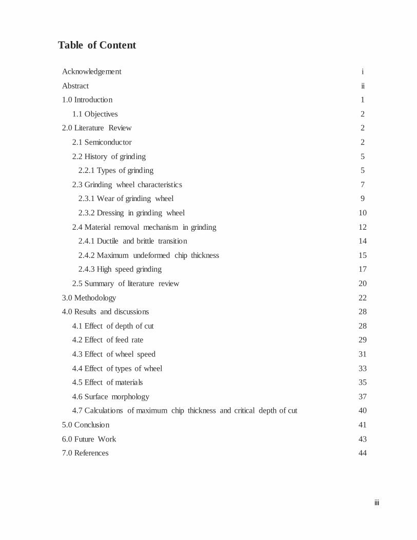
Table of Content
Acknowledgement i
Abstract ii
1.0 Introduction 1
1.1 Objectives 2
2.0 Literature Review 2
2.1 Semiconductor 2
2.2 History of grinding 5
2.2.1 Types of grinding 5
2.3 Grinding wheel characteristics 7
2.3.1 Wear of grinding wheel 9
2.3.2 Dressing in grinding wheel 10
2.4 Material removal mechanism in grinding 12
2.4.1 Ductile and brittle transition 14
2.4.2 Maximum undeformed chip thickness 15
2.4.3 High speed grinding 17
2.5 Summary of literature review 20
3.0 Methodology 22
4.0 Results and discussions 28
4.1 Effect of depth of cut 28
4.2 Effect of feed rate 29
4.3 Effect of wheel speed 31
4.4 Effect of types of wheel 33
4.5 Effect of materials 35
4.6 Surface morphology 37
4.7 Calculations of maximum chip thickness and critical depth of cut 40
5.0 Conclusion 41
6.0 Future Work 43
7.0 References 44
iv
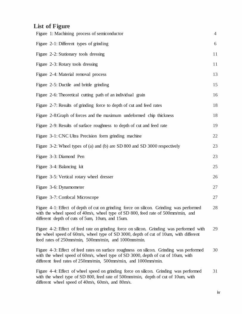
List of Figure Figure 1: Machining process of semiconductor 4
Figure 2-1: Different types of grinding 6
Figure 2-2: Stationary tools dressing 11
Figure 2-3: Rotary tools dressing 11
Figure 2-4: Material removal process 13
Figure 2-5: Ductile and brittle grinding 15
Figure 2-6: Theoretical cutting path of an individual grain 16
Figure 2-7: Results of grinding force to depth of cut and feed rates 18
Figure 2-8:Graph of forces and the maximum undeformed chip thickness 18
Figure 2-9: Results of surface roughness to depth of cut and feed rate 19
Figure 3-1: CNC Ultra Precision form grinding machine 22
Figure 3-2: Wheel types of (a) and (b) are SD 800 and SD 3000 respectively 23
Figure 3-3: Diamond Pen 23
Figure 3-4: Balancing kit 25
Figure 3-5: Vertical rotary wheel dresser 26
Figure 3-6: Dynamometer 27
Figure 3-7: Confocal Microscope 27
Figure 4-1: Effect of depth of cut on grinding force on silicon. Grinding was performed with the wheel speed of 40m/s, wheel type of SD 800, feed rate of 500mm/min, and different depth of cuts of 5um, 10um, and 15um.
28
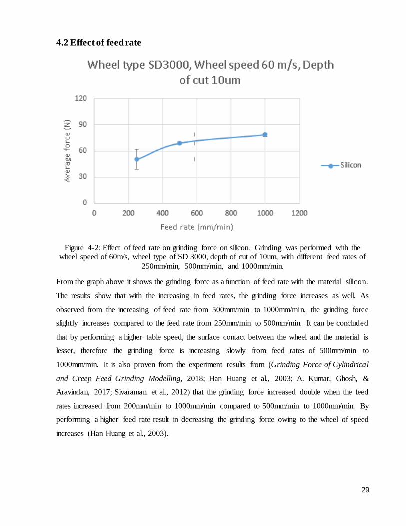
Figure 4-2: Effect of feed rate on grinding force on silicon. Grinding was performed with the wheel speed of 60m/s, wheel type of SD 3000, depth of cut of 10um, with different
feed rates of 250mm/min, 500mm/min, and 1000mm/min.
29
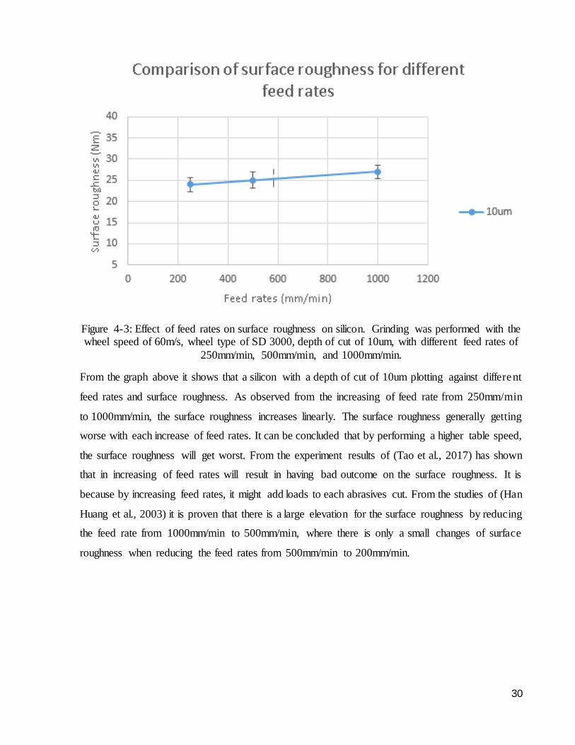
Figure 4-3: Effect of feed rates on surface roughness on silicon. Grinding was performed with the wheel speed of 60m/s, wheel type of SD 3000, depth of cut of 10um, with
different feed rates of 250mm/min, 500mm/min, and 1000mm/min.
30
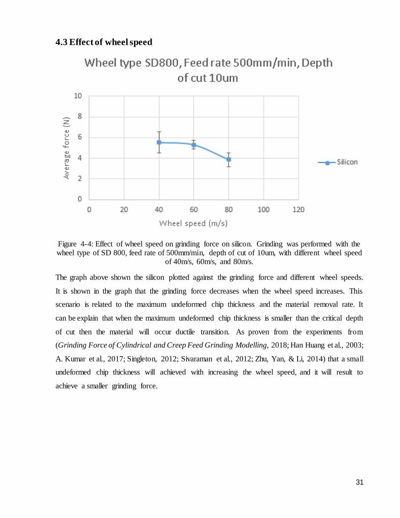
Figure 4-4: Effect of wheel speed on grinding force on silicon. Grinding was performed
with the wheel type of SD 800, feed rate of 500mm/min, depth of cut of 10um, with different wheel speed of 40m/s, 60m/s, and 80m/s.
31
v
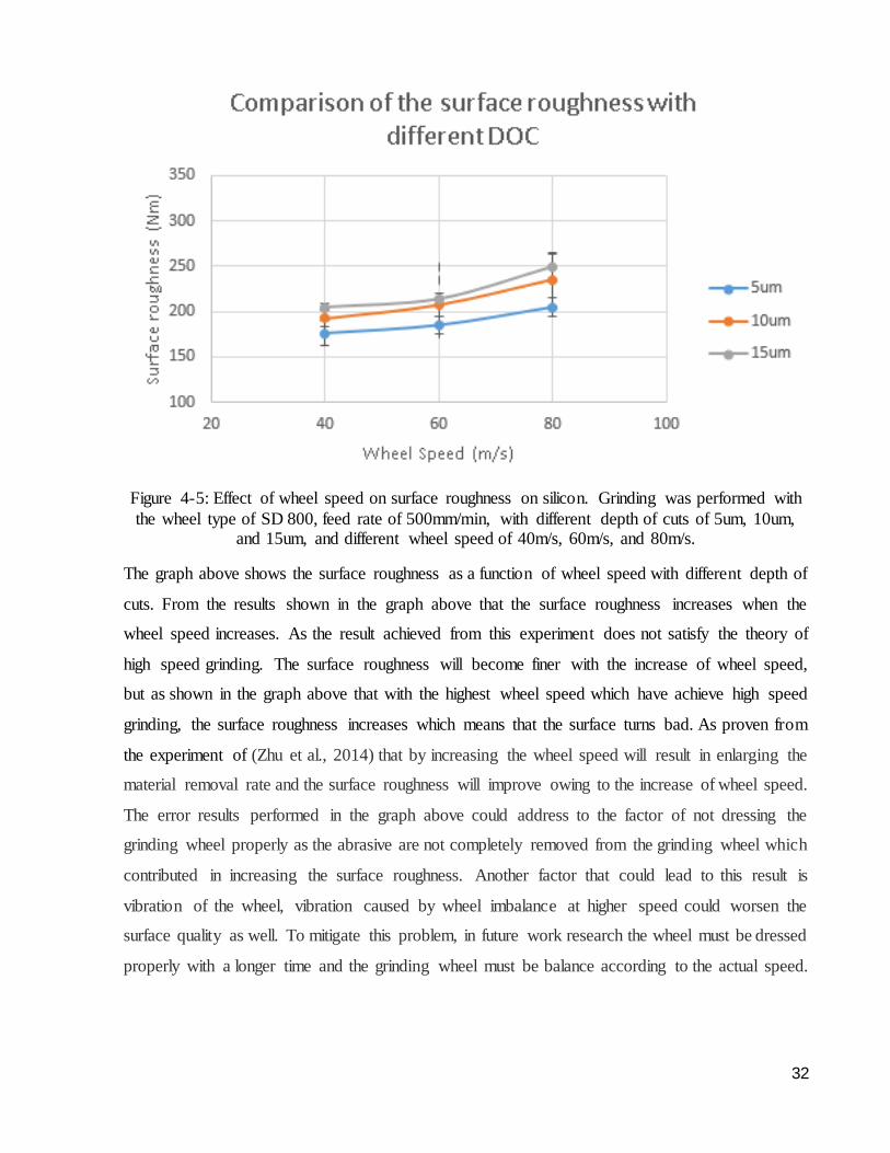
Figure 4-5: Effect of wheel speed on surface roughness on silicon. Grinding was performed with the wheel type of SD 800, feed rate of 500mm/min, with different depth of cuts of 5um, 10um, and 15um, and different wheel speed of 40m/s, 60m/s, and 80m/s.
32
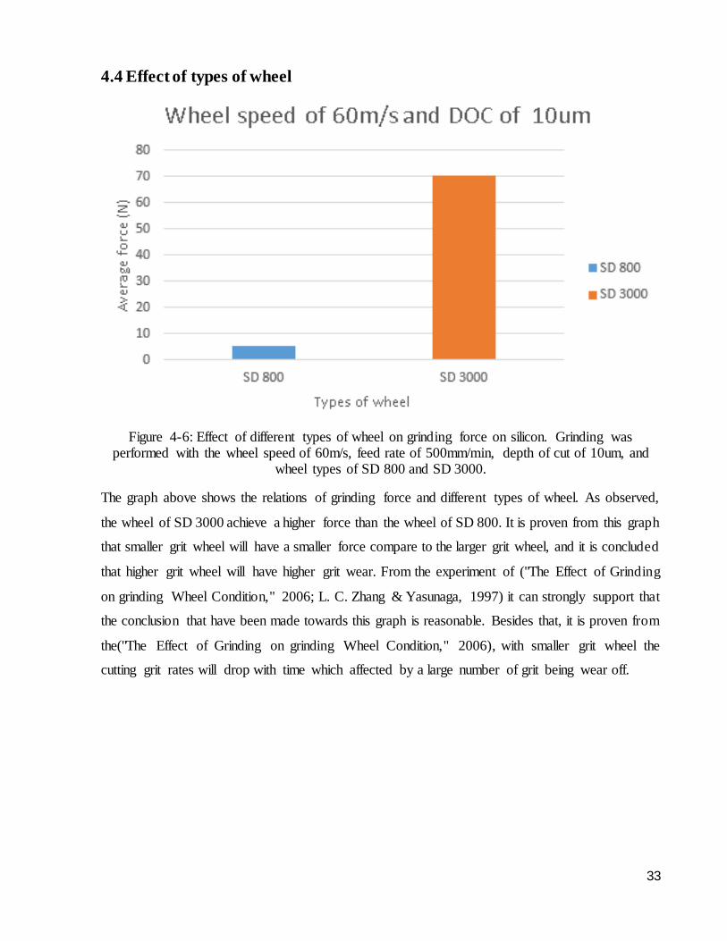
Figure 4-6: Effect of different types of wheel on grinding force on silicon. Grinding was performed with the wheel speed of 60m/s, feed rate of 500mm/min, depth of cut of 10um,
and wheel types of SD 800 and SD 3000.
33
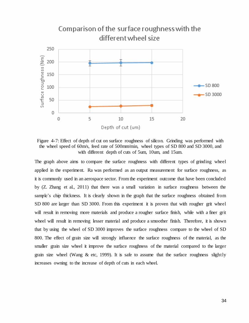
Figure 4-7: Effect of depth of cut on surface roughness of silicon. Grinding was performed with the wheel speed of 60m/s, feed rate of 500mm/min, wheel types of SD
800 and SD 3000, and with different depth of cuts of 5um, 10um, and 15um.
34
Figure 4-8: Effect of depth of cut on grinding force on silicon. Grinding was performed
with the wheel speed of 60m/s, wheel type of SD 3000, feed rate of 500mm/min, with different depth of cuts of 5um, 10um, and 15um.
35
Figure 4-9: Effect of depth of cut on grinding force on Gallium Arsenide. Grinding was
performed with the wheel speed of 60m/s, wheel type of SD 3000, feed rate of 500mm/min, with different depth of cuts of 5um, 10um, and 15um.
35
Figure 4-10: Effect of depth of cut on surface roughness on silicon and gallium arsenide. Grinding was performed with the wheel speed of 60m/s, wheel type of SD 3000, feed rate of 500mm/min, with different depth of cuts of 5um, 10um, and 15um.
36
Figure 4-11: Surface morphology – Effect of wheel speed on silicon. Grinding was performed with wheel type of SD 800, feed rate of 500mm/min, depth of cut of 15um,
with different wheel speed (a), (b), and (c) of 40m/s, 60m/s, and 80m/s respectively.
37
Figure 4-12: Surface morphology – Effect of types of wheel on silicon. Grinding was performed with the wheel speed of 60m/s, feed rate of 500mm/min, depth of cut of 15um,
with the different wheel types (a) and (b) of SD 800 and SD 3000 respectively.
38
Figure 4-13: Surface morphology – Effect of feed rate on silicon. Grinding was performed
with wheel type of SD 3000, wheel speed of 60m/s, depth of cut of 10um, with different feed rates (a), (b), and (c) of 250mm/min, 500mm/min, and 1000mm/min respectively.
39
List of table Table 1: Experiment parameter 22
Table 2: Characteristics of grinding machine 23
Table 3: Calculation of critical depth of cut 40
Table 4: Calculation of maximum undeformed chip thickness 40
1
1.0 Introduction
Semiconductor have been a very useful material for electrical industries and it is widely
used in the world as an electrical component. Both of the semiconductor silicon substrates (Si) and
gallium arsenide (GaAs) are one of the best semiconductor used to operate the electrical component.
The semiconductor have to gone through a machining process to achieve the final product of the
processes semiconductor material. The semiconductor are expected to achieve ductile removal
mode to able to obtain a good surface quality. However, Silicon has a relatively hard brittle material
unless they are machine in ductile mode on precision grinding machine.
There are several grinding machine types and each types of grinder has their own
characteristics. The grinding machine consist of a few important mechanism in order to operate the
grinding machine. Grinding wheel is one of the most essential mechanism in the grinding machine ,
the material of the grinding wheel is very important which it will affect the surface quality of the
material. The grinding wheel must be dressed before conducting the grinding operations. The
purpose of dressing the grinding wheel is to prevent the wheel from wear and it would affect the
grinding results. Furthermore, the material removal mechanism play an important role in the
grinding process. In the material removal process, the depth of cut, chip thickness, and the materials
transitions might occur.
In the process of grinding, there are three stages of process which are the sliding, ploughing,
and cutting that are involved in the material removal mechanism. This three processes are used to
achieve ductile removal mode and a good surface quality. Moreover, by depending on the grinding
force, the depth of cut and feed rates could be determined. Last but not least, the whole grinding
machine mechanism are very essential and each of the mechanism have done a huge contributed
to the grinding process.
2
1.1 Objectives
The objective of this thesis project is to familiarise with the grinding machine and to examine the
data collected by grinding semiconductors. The objectives of this thesis project are evaluated as
below:
To utilise high speed grinding to achieve ductile removal mode and high surface finish from
the semiconductor materials.
To understanding the material removal mechanism of the semiconductor in grinding though
the surface analysis.
To understand the effect of depth of cuts, wheel speed, types of wheel, and feed rate towards
the semiconductors.
2.0 Literature review
2.1 Semiconductor
Semiconductors are widely used in the electrical industries, people often used it as a
conductor or an insulator in the electrical device. In a semiconductor the mobility of the carriers is
affected by the temperature and the presence of charge impurities. At lower temperature the
mobility of carriers is weaken which results in carrier interaction with charge impurities, and it
react as an insulator(Green, 2019). At higher temperature the mobility of carriers is increase due to
electron escaping from the covalent bond. This results in higher amount of free electron flowing in
the semiconductor which increases the conduction in semiconductors, which this act as a conductor.
Semiconductors weren’t as great as metals, as the temperature rises the resistance got weaker which
the metal act opposite of it. A wafers with good reproduction quality will automatically leads to
produce a good yielding component and achieve a better device performance (Landry & Barron,
1993). Nowadays, semiconductor are overly used as an electrical component such as radio, mobile
phones, and etc.
There are several types of semiconductors, Silicon (Si) and gallium arsenide (GaAs) are the
two most essential semiconductors (Sze, 2007). Silicon is an indispensable conductors where it has
a relatively low defects, and it has become the most valuable component for the electronic devices.
According to (Shu, 2015), the advantages of silicon are: (i) The silicate and silica were made use
of 90% of the earth’s crust, as this is an essential product to produce silicon wafer, which happen
3
to produce the silicon wafer in a low cost. (ii) Rigidity and thermal conductivity are excellent. (iii)
A massive and highly purified wafer were easily grown and obtained.
Nowadays silicon has been widely used in the electronic industry not only because of its
good electronic properties but also the great mechanical properties (Petersen, 1982). When the
strain increases, the stress associated with the strain increases first mostly due to elastic
deformation, then approaches a limit called the upper yield stress and gradually decreases to the
lower yield stress. Eventually, the stress associated with the strain increases again fairly gradually
due to the enhancement of internal stresses induced, in fact, by the dislocation field (Petukhov,
2004). It was proven from (H. Zhang, López‐Honorato, Javed, Shapiro, & Xiao, 2012) that the
micro-crack with stress induction tends to introduce the fracture behavior which likely to have high
fracture toughness to the coating on silicon. In fact, silicon is well known to be strongly dependent
to the size of the material at the scale of micrometer and nanometer. From the statement above
shows that fracture toughness are not affected by the size despite in the scale of nanometer, while
on the other hand the silicon’s tensile strength are strongly affected by it (Sumigawa, Ashida,
Tanaka, Sanada, & Kitamura, 2015).
However, as both of the silicon and gallium arsenide are brittle material and not only by the
condition of a clean, reduced surface defect and the devise geometries being reduced, it must also
go through a complex process to produce a material with damage free, flat, and clean surfaces
(Landry & Barron, 1993). As compared to silicon, gallium arsenide have a great electron mobility
and high saturated electron. Due to the wide band gap of gallium arsenide, it doesn’t not get
sensitive with heat. Besides that, exclusively at a higher frequency the devices create lesser noise
compared to silicon(Atlantic Euipment Engineers, 2013). Gallium arsenide wafers will have a
better concentration of the remaining electrically operating impurities than silicon due to the poor
technology to purified gallium and arsenide as compete to the available method of silicon
(Buschow, Flemings, & Cahn, 2001).
Silicon substrate is a hard and brittle solid, but it has a relatively hard brittle material unless
they are machine in ductile mode on precision grinding machine. Semiconductor shows a sharp
decreasing in hardness, where by increasing the temperature of the material silicon and gallium
arsenide with degree Celsius of 500 and 200 respectively will starts to result in macroscopic
dislocation motion and also the plastic deformation. The element of the semiconductor with the
structure of diamond or sphalerite like silicon and gallium arsenide have the potential of stress-
strain reaction followed by an exceptional reduce of stress after the process of yield along with a
4
slight increase in stress with strain owing to the work hardening in the plastic deformation process,
and the deformation mostly happened in a low temperature. Generally the strain rate and
temperature sensitively affect the stress-strain element in the semiconductor. An increase in the
strain rate actually have the same effects with the decrease in temperature (Michler, Wasmer, Meier,
Östlund, & Leifer, 2007). The fabrication method for the wafer of silicon and gallium arsenide
generally the same because both of the materials are brittle (Landry & Barron, 1993).
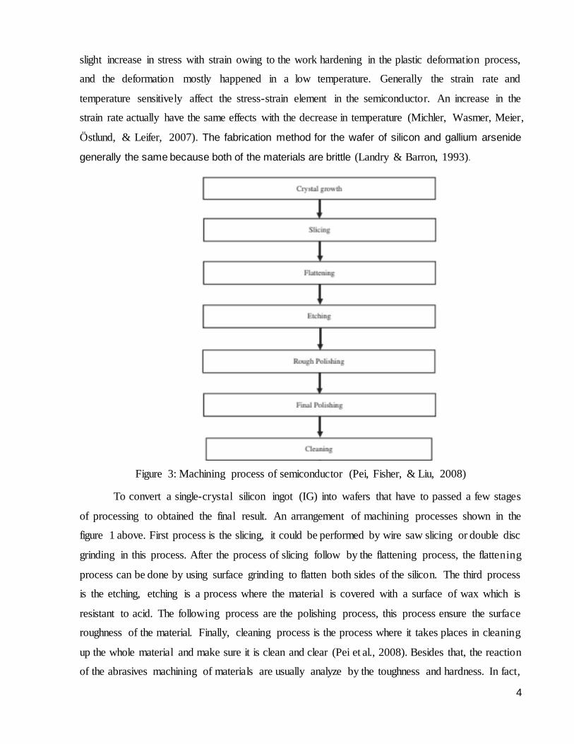
Figure 3: Machining process of semiconductor (Pei, Fisher, & Liu, 2008)
To convert a single-crystal silicon ingot (IG) into wafers that have to passed a few stages
of processing to obtained the final result. An arrangement of machining processes shown in the
figure 1 above. First process is the slicing, it could be performed by wire saw slicing or double disc
grinding in this process. After the process of slicing follow by the flattening process, the flattening
process can be done by using surface grinding to flatten both sides of the silicon. The third process
is the etching, etching is a process where the material is covered with a surface of wax which is
resistant to acid. The following process are the polishing process, this process ensure the surface
roughness of the material. Finally, cleaning process is the process where it takes places in cleaning
up the whole material and make sure it is clean and clear (Pei et al., 2008). Besides that, the reaction
of the abrasives machining of materials are usually analyze by the toughness and hardness. In fact,
5
the crack extensions are affected by the toughness of silicon with microstructures which contribute
in elongated grains. In the studies of (Xu, Jahanmir, Ives, Job, & Ritchie, 1996), it is proved that
the damage tolerance and toughness are strongly affected by the elongated grains in silicon.
2.2 History of grinding
In the early stage of grinding, the abrasive stone were used as a grinding tools to sharpen
knives, and weapons. The abrasive have been useful in the early life as a tools to produce a well-
shaped rocks and stone for construction of building, for example the pyramid (W. Brian Rowe,
2014). At a later stage, eating utensils were found out that it could be made by grinding out stones
by using abrasive. Other than using grinding to sharpen objects, grinding may be one of the earliest
inventions in machine operation to be able to produce a desired shapes. To build the Pyramids of
Egypt, big stone blocks were cut into desired size by sawing with a specific indecent model of
grinding machine, and the sandstone surfaces were smooth. Metal grinding first initiated around
2000 BC in ancient Egypt, which lead to the origins of metallurgy(Grinding Technology, 2008).
In the period of 800 and 600 BC it was believed that the India have invented the diamond
mining, and this was the only invention of diamonds until the century of nineteenth. Belgium was
one of the earliest country to utilise the abrasive which is made out of diamond powder in the
fifteenth century, it was then use to cut diamond and to produce soft finishing to manufacture watch.
In the beginning of metallurgy the grinding wheel have been invented in time of ancient Egypt, the
earliest invention of grinding wheel are made out of sandstone and manufacture with the method
of grind grain by using the crude mill. The earliest abrasive wheels were being manufactured in
India in the nineteenth century, and it was used for grinding gems. In 1860s, Brown & Sharpe
Company invented the first new grinding machine for sewing machine parts. In 1870s, Norton
Company invented the most welcome product of the grinding wheel which is the vitrified bond
grinding wheel. With the technology of grinding machine, grinding wheel plays an important tools
in the grinding machine to fully utilise the machine(Grinding Technology, 2008). Nowadays,
grinding played an important role in machining process and lots of grinding methods have been
invented for different demands on materials and specifications.
2.2.1 Types of grinding
The shape of the grinding wheel and the relationship between the wheel head and the
workpiece are based on many types of grinding processes (S. Chen, 2018). The types of grinding
are as follow: (i) Surface grinder. (ii) Cylindrical grinder. (iii) Internal grinder. (iv) Centerless
grinder. (v) Special grinding process. Different types of grinding has their characteristics and uses
6
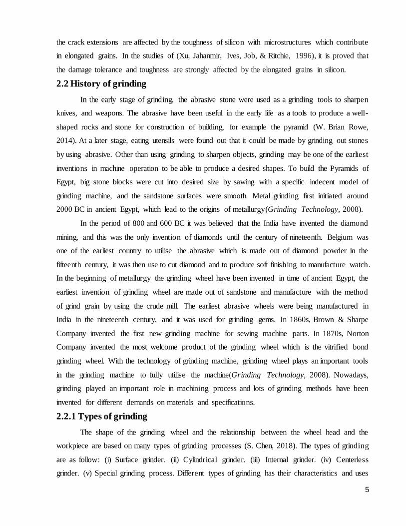
towards different material and methods. Different types of grinding are as shown in the figure 2-1
below:
Figure 4-1: Different types of grinding (S. Chen, 2018)
Among all the types of grinding the most commonly used grinding operations are the
surface grinder. The surface grinder are normally used to achieve irregular, flat, smooth, and
angular shapes (S. Chen, 2018). While rotating the wheel and object the material are being hold by
a chuck to produce a smooth finish surface. This results in good surface finish together with the
capability to grind to excessively high tolerances.
The cylindrical grinder do has a same trait as the surface grinder which is both of the grinder
have the exact same level of tolerances which is attainable with the surface finish. The only
difference between the two methods is, on cylindrical grinder both workpiece can be hold by the
chuck or between centers and let the wheel rotate(Samar, 2011). Cylindrical grinder is a machine
that can shape the outer face of the object as long as it has central axis of rotation (S. Liang & Shih,
2016).
Other than that, a centerless grinder is similar like the cylindrical grinder as it uses two
spinning wheel to support the workpiece firmly in place (S. Chen, 2018) . The rate of material
removal is define by the speed of rotation of the wheel (S. Chen, 2018). One of the most difficult
grinding types is the internal grinding. Internal grinding can develop a tapered, straight or formed
holes to produce an exclusive surface finish or similar tolerance (S. Chen, 2018). The grinding
wheel is rotated by a different motor head in the same way as the workpiece (S. Kumar &
7
Dhanabalan, 2018). Therefore, the grinding wheel can be modified accordingly for the depth of
cut(Schneider, 2011).
Lastly, the special grinding process designed for different types of work and methods. In
special grinding processes there are several grinders such as tool and cutter grinder, jig grinder,
and thread grinder. The tool and cutter grinder is mainly used to sharpen milling cutters and other
cutting mechanisms. It is commonly used for providing the tools to the metal and wood cutting
industries. Besides that, the tools and cutter grinder has a very high versatility and it can be used
to perform several grinding operations. Moreover, the jig grinder is designed to detect and precisely
grind holes and complex shapes. It is attached to a high speed air spindle to hold and drive the
grinding wheel. Thread grinding is normally perform on a grinding machine by using dressed
grinding wheel depending on the shape of the threads. It must be equip with a precision screw to
achieve the desire pitch on the threaded section (S. Chen, 2018).
2.3 Grinding wheel characteristics
Grinding wheels are created from several grain types in a large range of sizes in
combination with some bond materials and compositions(Grinding Technology, 2008). In
conventional abrasive wheels there are aluminum oxide and silicon carbide abrasives and are
produced with vitrified or resinoid bonds. While the superabrasives wheel contains diamond and
cubic boron nitride (CBN) and are made of with resin, metal bonds, and vitrified. For conventiona l
abrasive wheels it is generally covering the whole bonded abrasives, while the superabrasives
wheels is defined to a thinner rim to lessen the amount of costly CBN and diamond. Nowadays, all
the grinding wheels of conventional abrasives are basically aluminum oxide (A12O3) or silicon
carbine (SiC)(Grinding Technology, 2008); W.B.Rowe, 2010).
The maximum wheel speed of the cubic boron nitride (CBN) wheel is 200m/s, while the
maximum speed of the diamond wheel is only 80m/s, the diamond wheel has low heat resistant as
if it occurred a high temperature it will leads to diamond carbonization(B. Li, Ni, Yang, & Liang,
2014). The process of hard aluminum oxide is alumina with a hexagonal crystal similar to that of
natural abrasives of aluminum oxide which occur in different pureness and crystalliza t ion
degrees(Grinding Technology, 2008). Aluminum oxides consist of different concentrations of other
metal oxides either internationally introduced or as impurities(Grinding Technology, 2008). Many
types of abrasives aluminum oxide and a defined number of forms of silicon carbides are widely
used, which each has a special chemical composition and a collection of basic characteristics which
8
influence granular properties and grinding process which is helpful for specific task(Grinding
Technology, 2008).
Knoop or Vickers hardness test was used to determine the abrasives hardness in conjunction
of the static indentation hardness. Dynamic strength and toughness are very critical to the abrasives
property(Grinding Technology, 2008). When the abrasives grain employ or collide with the
workpiece, it is less expected to tear or fragment if it is very tough. Abrasives wear resistance are
depending on all these properties (W. B. Rowe, 2010). Generally the finer grits with the equivalent
material are less friable than expected as they are normally formed by crushing the coarser
material(Grinding Technology, 2008). All silicon carbide forms are significantly harder than
alumina and are equivalent to the toughest abrasives of alumina, and this sequence of physical
properties would say that alumina oxide might not be as good as silicon carbide for fine grinding
operation(Grinding Technology, 2008). Grinding wheel that are superabrasives consist of diamond
and cubic boron nitride (CBN). Normally grinding wheel with high wheel speed are made out from
superabrasives (W. B. Rowe, 2010). The profit gain from the potential of highly increasing the
wear life and redress life of the grinding is due to the cost of the abrasives (W. B. Rowe, 2010).
Both diamond and cubic boron nitride (CBN) are well known as hard materials and they
are very useful in cutting hard brittle(S. Chen, 2018; Grinding Technology, 2008; W. B. Rowe,
2010). Due to its significant high hardness and wear resistance, the CBN is able to commit to a
broad range of materials (W. B. Rowe, 2010). To grind hard ceramics a harder abrasives like
diamond is preferred (W. B. Rowe, 2010). Conventional abrasives are not designed to grind hard
ceramics because the material they are made out of are hard and brittle and that will cause an
extremely high wear rates (W. B. Rowe, 2010). In between both of the superabrasives grinding
wheel, the thermal stability in CBN is greater than diamond(Grinding Technology, 2008). In the
temperature of 800 degree Celsius, diamond is thermally stable in the natural atmosphere(Grinding
Technology, 2008). In a higher temperature, CBN wheels with vitrified bonds can perform better
than the diamond in a much broader range of vitrified bond during the manufac ture
process(Grinding Technology, 2008). Due to the graphitization and carbon diffusion, diamond is
not suggested to grind most of the rigid materials (S. Chen, 2018; Grinding Technology, 2008; W.
B. Rowe, 2010)
To grind hard and difficult materials, diamond is the most desire choice to choose because
of its wear resistance and excessively hardness that will not easily wear the wheels (S. Chen, 2018).
Besides that, diamond has become the most effectively dressing tool material to sharpen all types
9
of abrasives wheel (S. Chen, 2018). The grit and the grits number is linked with the grain size are
determined by a series of standard sieves during the production of the grinding wheel (S. Chen,
2018). However, the heat conductivity level for resin bond material are generally low, thus heat
produce during the grinding process will not simply transferred to the wheel. Other than that, when
a higher grit size was performed, to fit the abrasives tightly the resin bond have to be thicker (Z.
Zhang, Huo, Wu, & Huang, 2011). As according to (S. Chen, 2018), a specific shape of the grinding
wheel is chosen based on: (i) The workpiece material that are going to be grind. (ii) The standard
of surface finish and the accuracy of grinding. (iii) Parameters of grinding. (iv)The condition of the
grinding.
2.3.1 Wear of grinding wheel
Grinding wheel performance can be effectively affected by the wheel surface and wheel
wear (W. Brian Rowe, 2014). During the grinding process, wheel wear influences the form of the
cutting edges and it can cause difference contact in the kinematics zone. Different types of wheel
used in different manufacturing process determine the rate of wheel wear (S. Chen, 2018; Singleton,
2012). The wear in grinding wheel affect the quality and efficiency of the workpiece (Singleton,
2012).
In order to examine the wheel wear condition, the wheel radius reduction was measured
(Singleton, 2012). Regardless the wear type, the components dimensional tolerance is critical and
it can negatively influence the surface integrity (Singleton, 2012). While the wear involved with a
standard abrasive grinding wheel are much lower compared to high-speed steel or carbide milling
and turning operations, the production of tool wear is comparable (Singleton, 2012).
The mechanism of wear in the steady stage was represented as attritious wear when it do
not involve dressing and truing. Due to the increasing number of material removed it is strongly
affected by the increment of grits introducing the wear flats area. As the same concept, the grinding
force will generate a higher force when the rate of attritious wear is high, as this will contribute to
damage the workpiece. The definition of attritious wear is when wear mechanism occurred at a flat
surfaces (Liao, Li, & McSpadden, 2000). It is also proven by (Zeng, Li, Pei, & Treadwell, 2005)
that the increase of grinding force are affected by the increment of the wear flats owing to the
attritious wear. The grinding wheel life highly dependent on the attritious wear, but the attritious
wear slightly benefited to the reduction of wheel volume (Z. Liang et al., 2012). According to
(Singleton, 2012), the wheel will face failure if the wheel is not redressed. Due to the extreme
attrition of the grains contributed from the power and force, the wheel experienced a grain and
10
bond fracture (Singleton, 2012). This can results to an impressive loss to the wheel radius, and also
has the response of refreshing the surface of the wheel and cause the force and power to be reduce
(Singleton, 2012). It was concluded in the experiment of (Han Huang, 2003) that the wheel wear
rate was significantly decrease and the surface finish was having a small improvement due to the
increase of depth of cut. The surface roughness was badly affected with the increase of depth of
cut and feed rate. In the situation where increasing the depth of cut and feed rate, it will cause
additional force acting on each abrasive and it will produce a high temperature during the grinding
process which will result in damaging the wear of abrasive (Tao, Yaoyao, Laakso, & Jinming,
2017).
2.3.2 Dressing in grinding wheel
Before the grinding process, the grinding wheel must be dress. In the manufacture of
component grinding is mostly the last machining procedure and it have a great demand on
constructing surface quality and accuracy (Jackson & Davim, 2011). Before conducting the
grinding process, the bonded and vitrified wheels are dressed. A straightness or specified model is
use to exclude the deviations by using truing (Opoz, 2012). Cutting desire can be improve by
removing the unwanted abrasive grains, and this is one of the reason of dressing the grinding wheels
(S. Chen, 2018). A uniform random distributed cutting edge is perform by dressing to obtain a good
cutting surface (S. Liang & Shih, 2016).
Superabrasives wheels specified built for grinding in a long term period with a minimum
redressing. Dressing is an operation that manages to remove unwanted material around the
abrasives grains to produce a wide wheel surface, and this is essential for the vitrified and resin
bonded superabrasives wheels. Carbide or alumina abrasive sticks may be used as a tools for
dressing sometimes. With frequently use of the abrasives sticks, the abrasives wheels will wears
and lessen the redress life. Another approach of the dressing is to improve the removal rate of
grinding process when the grinding wheel has a clear surface. After the wheel were used to perform
a few grinding operations, the grinding wheel are to be dressed to add new grains to the process of
cutting and to maintain its initial shape (Opoz, 2012). The carbide wheel are seldom used as a
dressing tools for the metal bond multi- layer superabrasives wheels. Sometimes, a carbide wheel
were used to dress the metal-bond multi- layer superabrasives.
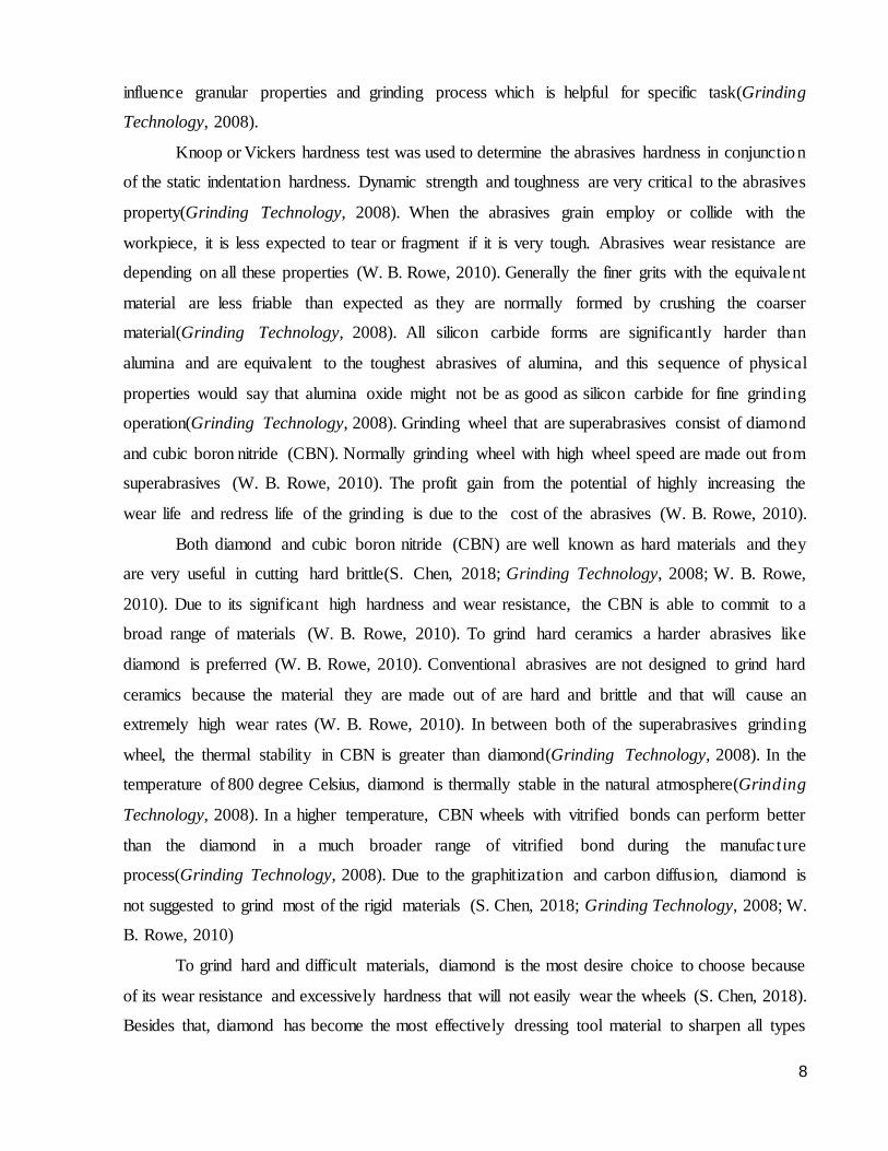
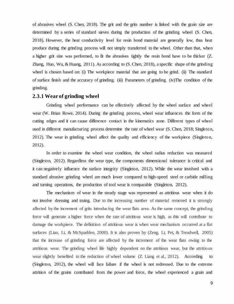
Basically, the two mostly used dressing tools are the stationary tools and the rotary tools.
Conventional abrasives are normally dressed using the stationary dressing tools which contain
single-point diamond (SD) and impregnated diamond (ID). Form dressing tools come in a few
11
variety of shapes that consists of round sharp-shaped tools. To not get involved of wear in rapid
dressing tools, the rotary dressing tools are usually used to dress the diamond wheels, vitrified
cubic boron nitride (CBN), and resin bonded CBN. The rotary dressing tools might be structure in
a limit spaced disc with a surface covered by diamond perform surrounding the periphery or a cup
with a surface covered by diamond somewhere near the edge. By bringing the width of the roll
together with the grinding wheel, it is proven that this is the best rotary dressing tools with the use
of motor. The dressing process normally operates when the grinding wheel is running in a regular
speed, this limit the errors of the wheel from a little unbalance phase to a minimum phase (Opoz,
2012). It is also important to perform the wheel balancing carefully during the dressing process (W.
Brian Rowe, 2014). It is justify that coarse dressing method identify to have a minimum grinding
force and grinding power but a surface roughness with a huge work material (Opoz, 2012). The
figure below shows the examples of stationary dressing tools and rotary dressing tools.
Figure 2-2: Stationary tools dressing (Jackson & Davim, 2011)
Figure 2-3: Rotary tools dressing(Jackson & Davim, 2011)
12
2.4 Material removal mechanism in grinding
The wheel wear and material removal object must be taken into account for material
removing process when undergoing the process of machining with grinding wheels (Opoz, 2012).
Other than the grinding geometry, the material properties also strongly contributed to the effect of
surface quality and removal process mechanism in high speed grinding process (Yin & Huang,
2004).
To fully utilise the potential of the removal rate without affecting the surface quality, the
grinding parameter have to be concise to achieve the most effective grinding process for the
ceramics with great material properties. By having the process of damaging the workpiece owing
to the crack causing by the grinding process are usually applied to achieve removal rate with faster
process and this process is cost saving. Thus, it is important to understand and be familiar with the
properties of the material removal process and to be concise with the grinding parameter that are
going to process as an outcome. Material removal mechanism was strongly affected by the
dislodgement of the grain or the boundaries of the grain having a lateral crack (Agarwal &
Venkateswara Rao, 2010; Yin, Huang, Ramesh, & Huang, 2005).
By acknowledging the ground surface quality and knowing the topography of the grinding
wheel in combining with the performance of the grinding operations and material removal essential,
the grinding performance is determined by the topography of the grinding wheel and it is also one
of the most common factor to it (Opoz, 2012). Several cuts that performed from an amount of
individual grain work material interacted act as a grinding material removal process (Singleton,
2012). From the studies (Agarwal & Venkateswara Rao, 2010) it is stated that the surface finish
and the surface morphology are totally not being affected by the increment in material removal rate.
With constantly dressing and improving the grinding wheel surface it is likely to achieve high
removal rate (Jahanmir, Ramulu, & Koshy, 1999).
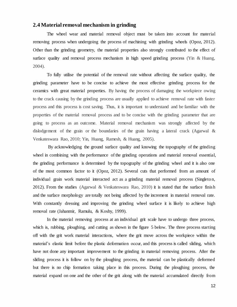
In the material removing process at an individual grit scale have to undergo three process,
which is, rubbing, ploughing, and cutting as shown in the figure 5 below. The three process starting
off with the grit work material interactions, where the grit move across the workpiece within the
material’s elastic limit before the plastic deformation occur, and this process is called sliding, which
have not done any important improvement to the grinding in material removing process. After the
sliding process it is follow on by the ploughing process, the material can be plastically deformed
but there is no chip formation taking place in this process. During the ploughing process, the
material expand on one and the other of the grit along with the material accumulated directly from
13
the grit till the material removal happen with the chip formation (Opoz, 2012). The process from
sliding to ploughing and from ploughing to cutting it all depends on depth of grit that are going to
go through the work material (Rowe, 2009). Even though the process of sliding and ploughing does
not made a huge effect to the material removal, but they can be negatively affect the grinding
process by adding an extreme rate of wheel wear and surface misrepresentation cause by the rising
specific energy and friction, with a relatively rising in temperature (Opoz, 2012).
(Takenaka & Sasaya, 1966) says that the ploughing process was greatly relying on the
shape of the grit. The abrasives grain that are primarily sliding, occur a different wear of grains that
happened in heavy chip removing process (W. Brian Rowe, 2014). In the process of high speed
grinding, the material removal mechanism will be affected by the grinding wheel speed which
mainly controlling the hardness of the strain and thermal softening (Tian, Fu, Xu, Li, & Ding,
2015). To achieve a high removal rate, usually a relatively huge depth of cut is considered (H.
Huang & Liu, 2003). With the effective process of rough composition is to increase the wheel
speed and the feed rate, and result in enlarging the material removal process rate with not making
any contribution to the wheel wear (Jahanmir et al., 1999). In this case, the material removal
process are in brittle transition. Chip removal happen in the starting of the interactions of the
individual grain occur in down-cut grinding. During the conventional in the down-cut grinding, the
force applied will be relatively low, and the surface roughness become useful and the wheel wear
was also decreased. In the process of up-cut grinding, the individual grain have an interaction
against the workpiece, and after the process the chip removal is obtained (W. Brian Rowe, 2014).
Figure 2-4: Material removal process(Winter, 2016)
14
2.4.1 Ductile and brittle transition
According to (Bifano, Dow, & Scattergood, 1991; S. Liang & Shih, 2016), the following
guidelines are widely applicable for the selection of a suitable grinding wheel: (i) To choose a hard
surface wheel to cause the soft material to slower down the wear and a soft surface wheel to cause
the hard material to ease self-sharpening. (ii) To choose a hard wheel to grind the ductile material
and choose a soft wheel to grind the brittle material. (iii) To choose a softer wheel to acquire a
good surface finish and a harder wheel to maximize the material removal rate. Today, through the
enhancement of the ultraprecision machine tools which leads to minimum error motion and greater
stiffness, brittle materials that are going through a machining process of ductile mode is now a
popular technique used by many to achieve higher precision, improved surface finish and lesser
costs (Shimada, Inamura, & Ikawa, 1997).
It is notable fact that there exists brittle and ductile materials transition in material removal
mechanism. The brittle to ductile transition occur when the critical value is more than the depth of
cut which are important for the workpiece to be machined (Bifano et al., 1991; Shimada et al.,
1997). Therefore, plastic deformation is superior to brittle fracture when the critical value is larger
than the depth of cut in terms of energy consumption (Bifano et al., 1991; S. Liang & Shih, 2016).
During the brittle material undergoing a plastic deformation process, surface finishes are the same
to those accomplished polishing or lapping are achieved (Bifano et al., 1991). In brittle transition,
the material removal process is conducted by propagation and intersection of cracks, while for the
ductile transition it creates material behavior of a plastic in a state of extremely sheared machining
chips (Bifano et al., 1991).
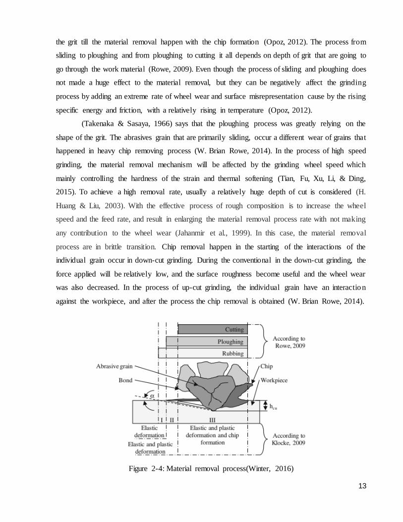
In the studies of (Young, Liao, & Huang, 2007) it is proven that with the critical depth of
cut larger than the maximum undeformed chip thickness then it will achieve ductile transition
grinding. As shown in the figure 2-5(a) below, through the ductile regime grinding process, it
shows that there weren’t any sign of cracks on the surface but the process are undergoing the elastic
deformation, plastic ploughing, and micro crack removal. Then, in figure 2-5(b), in the ductile-
brittle grinding process, with the increment to maximum, the micro crack starting to occur on the
surface of work material and produces some cracking results in the process of chip formation.
Finally, in figure 2-5(c), the brittle grinding process, by increasing it to the maximum, it is shown
on the figure that the material are completely eliminated by the brittle fracture and resulting a
massive crack on the surface. Brittle regime is the term used to define this method of material
removal mode (Dai et al., 2018).
15
Figure 2-5: Ductile and brittle grinding(Dai et al., 2018)
The model acquired from the formula describes the critical depth of a fracture occur during the
indentation of brittle materials (Lawn, Jensen, & Arora, 1976). Referring to the Griffith fracture
propagation criterion, the formula indicates a critical depth of indentation,
𝑑𝑐 =𝐸𝑅
𝐻…………………………………………… (1)
and the dc shown in the formula appear to be the critical indentation depth, where E is well known
as the elastic modulus, R appear to be the material’s fracture energy, and H indicates the hardness
of the material. Due to the material that shows a plastic area around the crack tip, the R from the
formula above can be found in Griffith’s classical crack propagation analysis. One way to define
small scales of the fracture energy is by substituting it with a dimensionally equivalent
measurement of the energy needed to propagate cracks are,
𝑅 =𝐾𝑐
2
𝐻….…….…..….…………….……………. (2)
For the indentation, the formula 𝑘𝑐
2
𝐻 has been subjected to an effective way to indicate the brittleness
(Marshall and Lawn, 1986). This quantity can be substituting in with critical depth model of
equation that are shown above to achieve,
𝑑𝑐 ∝ (𝐸
𝐻) (
𝐾𝑐
𝐻)
2
……….……. …………………….. (3)
and this shows a formula to measure the brittle transition depth of cut (Bifano et al., 1991). With
the application of the maximum undeformed chip thickness lesser than the critical depth of cut,
hm< dc, the surface are being examined as ductile transition mode. While when hm >dc, then the
surface will be examined as brittle transition mode which the surface involve crack propagation
during machining process (S. Chen, 2018).
2.4.2 Maximum undeformed chip thickness
By comparing the milling process and making assumptions on equally spaced cut points
near the wheel periphery was used in the earliest stage of chip thickness in grinding process
16
(Singleton, 2012). By using the abrasives grains the equivalent chip thickness is normally used to
measure the depth of material removal and it is nearly the same to the harshness of force applied
on the grains than in depth of cut (W. Brian Rowe, 2014). In a research of grinding process, it is
essential to significant process the undeformed chip thickness, exclusively in the section of
machining hard materials (S. Chen, 2018). During the operations of chip generation and surface
information, the wheel model and spec highly contributed in this process (S. Chen, 2018).
It is proven by (Yin & Huang, 2004) that when the grinding speed increases, an
improvement of surface finish will occur when the maximum undeformed chip thickness is reduce.
Other than the force applied and chip thickness, the process of edge shape cutting strongly affected
to the chip forming performance (Jahanmir et al., 1999). In terms of building a theoretical model
to determine the chip thickness, the grinding force is performed from the relationship between the
chip condition and surface quality (S. Chen, 2018). The chip geometry can be achieve when the
grinding wheel depth of cut and the amount of active abrasives grain were determined (S. Chen,
2018).
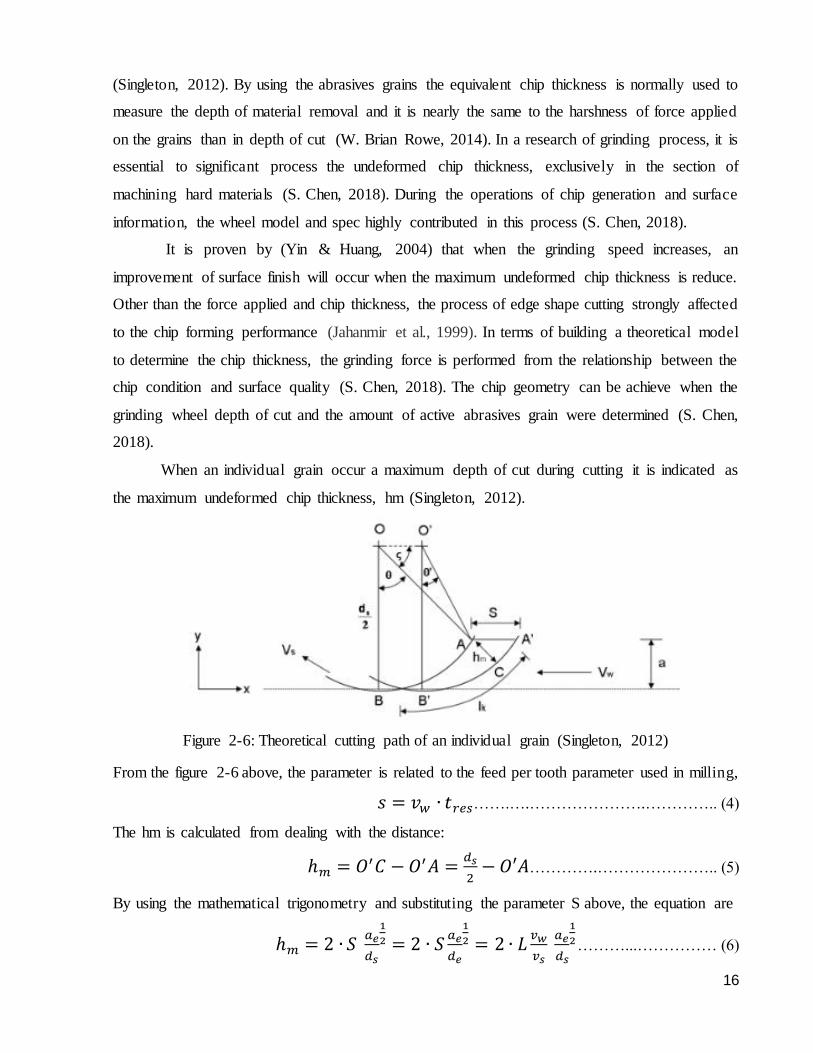
When an individual grain occur a maximum depth of cut during cutting it is indicated as
the maximum undeformed chip thickness, hm (Singleton, 2012).
Figure 2-6: Theoretical cutting path of an individual grain (Singleton, 2012)
From the figure 2-6 above, the parameter is related to the feed per tooth parameter used in milling,
𝑠 = 𝑣𝑤 ∙ 𝑡𝑟𝑒𝑠…….….………………….………….. (4)
The hm is calculated from dealing with the distance:
ℎ𝑚 = 𝑂′𝐶 − 𝑂′𝐴 =𝑑𝑠
2− 𝑂′𝐴………….………………….. (5)
By using the mathematical trigonometry and substituting the parameter S above, the equation are
ℎ𝑚 = 2 ∙ 𝑆 𝑎𝑒
𝑑𝑠
1
2 = 2 ∙ 𝑆𝑎𝑒
𝑑𝑒
1
2 = 2 ∙ 𝐿𝑣𝑤
𝑣𝑠 𝑎𝑒
𝑑𝑠
1
2………...…………… (6)
17
Where L indicates the distance between the cutting edges in unit (mm). The amount of cutting
points near any line of the wheel periphery K is calculated by,
𝐾 = 𝐶 𝜋 ∙ 𝑑𝑒 ∙ 𝑏𝑐 =𝜋∙𝑑𝑠
𝐿 ……………………………….. (7)
Where C indicates the amount of cutting points as per unit area of the wheel(1
𝑚𝑚2 ), where the 𝑏𝑐
indicate in the formula as the chip width. By dealing with L and calculate the chip width with the
maximum chip thickness, hm is then determined as
ℎ𝑚 =4
𝐶∙𝑟
𝑣𝑤
𝑣𝑠
𝑎
𝑑𝑠
1
2
1
2
……………………………………. (8)
where r indicates the ratio of the chip width to the thickness (Singleton, 2012). The advantages of
a smaller maximum undeformed chip thickness are, the layers that are being damage during the
grinding process are lesser and the surface roughness will be smoother, but it require more energy
to produce the material removal process (Zhou, Guo, & Wang, 2017).
2.4.3 High speed grinding
High speed grinding are freshly introduced as an effective grinding process and contained
a high capability of achieving a good surface quality with great productivity as compared to the
normal grinding (J. Chen, Shen, Huang, & Xu, 2010). High speed grinding highly performed for a
good surface quality with a relatively high efficiency (Klocke et al., 1997). By reducing the grinding
force, the high wheel speed can reduced the undeformed chip thickness (J. Chen et al., 2010; Han
Huang, Yin, & Zhou, 2003). Other than that it is proven from (J. Chen et al., 2010) that using the
brazed diamond wheel in high speed grinding will achieve a great performance (J. Chen et al.,
2010).
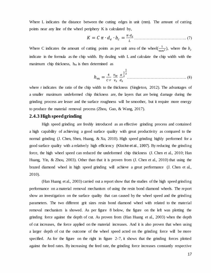
(Han Huang et al., 2003) carried out a report show that the studies of the high speed grinding
performance on a material removal mechanism of using the resin bond diamond wheels. The report
show an investigation on the surface quality that can caused by the wheel speed and the grinding
parameters. The two different grit sizes resin bond diamond wheel with related to the material
removal mechanism is showed. As per figure 8 below, the figure on the left was plotting the
grinding force against the depth of cut. As proven from (Han Huang et al., 2003) when the depth
of cut increases, the force applied on the material increases. And it is also proven that when using
a larger depth of cut the outcome of the wheel speed acted on the grinding force will be more
specified. As for the figure on the right in figure 2-7, it shows that the grinding forces plotted
against the feed rates. By increasing the feed rate, the grinding force increases constantly respective
18
with the feed rates. As when the feed rates are performed in a higher speed, the force applied on
the material are getting more linear towards the end.
Figure 2-7: Results of grinding force to depth of cut and feed rates(Han Huang et al., 2003)
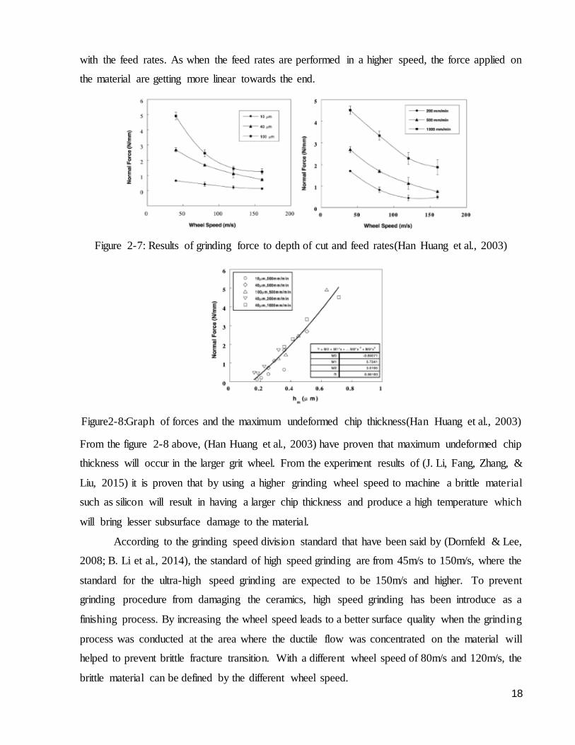
Figure2-8:Graph of forces and the maximum undeformed chip thickness(Han Huang et al., 2003)
From the figure 2-8 above, (Han Huang et al., 2003) have proven that maximum undeformed chip
thickness will occur in the larger grit wheel. From the experiment results of (J. Li, Fang, Zhang, &
Liu, 2015) it is proven that by using a higher grinding wheel speed to machine a brittle material
such as silicon will result in having a larger chip thickness and produce a high temperature which
will bring lesser subsurface damage to the material.
According to the grinding speed division standard that have been said by (Dornfeld & Lee,
2008; B. Li et al., 2014), the standard of high speed grinding are from 45m/s to 150m/s, where the
standard for the ultra-high speed grinding are expected to be 150m/s and higher. To prevent
grinding procedure from damaging the ceramics, high speed grinding has been introduce as a
finishing process. By increasing the wheel speed leads to a better surface quality when the grinding
process was conducted at the area where the ductile flow was concentrated on the material will
helped to prevent brittle fracture transition. With a different wheel speed of 80m/s and 120m/s, the
brittle material can be defined by the different wheel speed.
19
For brittle material ductile transition it is strongly affected by the maximum undeformed
chip thickness value, which by increasing the wheel speed effectively affect the results of the
maximum undeformed chip thickness as well. It is proven in the experiment that by diamond
grinding wheel with speed of 120m/s will effectively improve the grinding quality. Brittle material
will not achieved brittle transition when the material are being grinded with higher wheel speed
during the high speed grinding process (B. Li et al., 2014). Due to the circumstances of surface
finish, grinding wheel, and wheel speed, the performance of the grinding could be improve with
conducting at a higher speed and it will reduce the maximum undeformed chip thickness. For a
different wheel speed of high speed grinding could affect the surface contact between the abrasive
grit and the material, as it will significantly enlarged the depth of each grit that will pass through
the material without having fracture crack generation. It was studied from (Yin & Huang, 2004)
that with increasing the wheel speed will result the grinding force to be decrease and also increase
the toughness and hardness of the material.
High speed grinding was introduced as a process which was considered as a tool to optimize
cost and achieve high efficiency during machining process.(Han Huang, 2003). From the studies
of (Agarwal & Venkateswara Rao, 2010) it is stated that in the comparison of high speed grinding
and conventional grinding there were not much changes in the form of surface morphology and the
roughness of the surface as well. The ceramics properties will not have any reduction in fracture
strength which affected by the high removal process rate by performing the high speed grinding
(H. Huang & Liu, 2003). High speed grinding was introduced to optimize cost for grinding process
where polishing process are very expensive, as both of the process aims to achieve a better surface
quality, therefore high speed grinding was performed to shorten the possible time for polishing
process to optimize the cost production of grinding process (N, Hung, Tung, & Long, 2016)
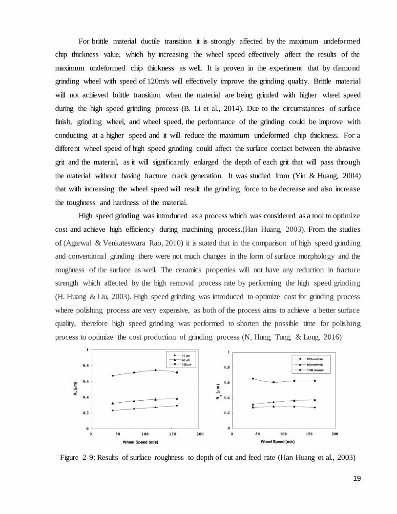
Figure 2-9: Results of surface roughness to depth of cut and feed rate (Han Huang et al., 2003)
20
As per figure 2-9 above the left graph represent the surface roughness which performed under
different wheel speed and in terms of different depth of cut. It have been shown clearly in the
experiment of (Han Huang et al., 2003), with the decrease of depth of cuts owing to the increase
of wheel speed, the surface roughness decreases which means that the surface roughness improved
and achieving a better surface. Nonetheless, as observed from the figure above by increasing the
wheel speed the surface roughness are slightly increasing as well. However, from the right graph
in figure 10 shows the relation of surface roughness and wheel speed with different feed rates. It is
shown that when the feed rates increases from 500mm/min to 1000mm/min the surface roughness
have a huge improvement, and the surface roughness slightly increases when the feed rates
increases from 200mm/min to 500mm/min. It is proven from (Han Huang et al., 2003) that with
the increase of feed rates and depth of cut it will damages the surface of the material and increases
the surface roughness. During the grinding process of the ceramics, by increasing the depth of cut
will usually contribute to a larger grinding force but also produce a negative effect to the surface
finish. By maintaining the grinding parameters being constant, with increasing the depth of cut
would strongly affect the coolant to not being able to have much contact between the ground of
grinding, therefore the effect of cooling were being reduce (H. Huang & Liu, 2003).
2.5 Summary of literature review
Semiconductor materials like silicon and gallium arsenide have hard hardness and
brittleness, as both of the materials have to go through a machining process before conducting the
grinding experiment. There are several types of grinding, but the most common type of grinding
are surface grinding which were performed in this thesis experiment. Moreover, the characterist ics
of grinding wheel are essential as different types of grinding wheel have different effect on
materials. For instance, grinding wheel with different grit size may result in different grinding force
and surface roughness. Other than that, grinding wear occurred in every grinding process as wheel
wear affect the form of cutting edges and it could cause difference contact in kinematics zone. On
top of that, wheel wear could affect the quality and efficient of the experiment. Dressing process
are crucial before conducting the grinding experiment, as the dressing procedure aims to remove
the abrasives particle on the wheel and reduce the vibration during the grinding process. As for the
material removal process it consists of three stages which are the sliding, ploughing, and cutting.
In the three process each performed an essential role in machining and grinding the workpiece to
achieve a better surface quality. Semiconductors like silicon and gallium arsenide have hard
hardness and brittleness, as both of the materials could achieve brittle fracture to ductile transition

21
with levelling the wheel speed. It is proven that when the critical depth of cut is larger than the
maximum undeformed chip thickness then the material could achieve ductile transition. High speed
grinding was introduced as an effective grinding process where it could provide a better surface
quality and surface roughness by increasing the wheel speed. With different grinding parameter
used, it could improve the surface roughness, surface quality, and reduce the grinding force. High
speed grinding are cost effective process and it could provide a better surface finish with higher
speed.
22
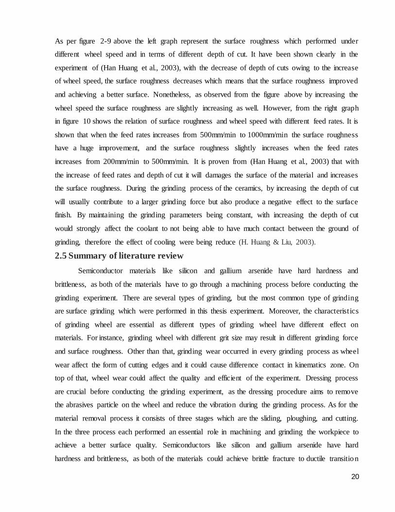
3.0 Methodology
This thesis experiments were conducted using the CNC Ultra Precision Form Grinding
Machine (Okamoto UPZ315Li). Due to the topic of precision grinding of semiconductor, this is a
suitable machine to conduct this experiment as the machine can operate in high speed grinding
which met the requirement of this experiment. In this experiment, the both semiconductors material
that are going to be examine are Silicon (Si) and Gallium Arsenide (GaAs). The parameters that
are used to conduct the experiment are, wheel type of SD 800 and SD 3000 which are the resin
bond wheel, depth of cut of 5um, 10um, and 15um, feed rates of 250 mm/min, 500 mm/min, and
1000mm/min, lastly the wheel speed of 40m/s, 60m/s, and 80m/s. The experiment parameter are
tabulated in the table below:
Table 5: Experiment parameter
Experiment details Parameter
Material Silicon (Si), Gallium Arsenide (GaAs)
Wheel speed 40m/s, 60m/s, and 80m/s
Types of wheel SD 800 and SD 3000
Feed rate 250mm/min, 500mm/min, 1000mm/min
Depth of cut 5𝜇𝑚, 10 𝜇𝑚, and 15 𝜇𝑚
The goals of this experiment are to determine the force applied to the material during grinding
process, and by using the confocal microscope to examine the surface roughness of the material.
Each measurement will be repeated twice to obtain a more precise force results as taking the
average forces between the two experiments as the final force results for the measurement.
Figure 3-1: CNC Ultra Precision form grinding machine (Okamoto UPZ315Li)
23
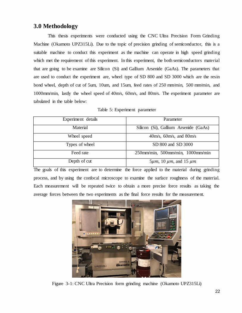
Table 6: Characteristics of grinding machine
X-axis (Table horizontal movement)
Y-axis (Wheel vertical movement)
Z-axis (Wheel cross movement)
Motor 2 sets * 1200W 750W 500W
Feed Speed 0-100m/min 1000mm/min 1000mm/min
Jog Speed - 1-1000mm/min 1-1000mm/min
Minimum setting unit 0.1𝜇𝑚 0.1𝜇𝑚 0.1𝜇𝑚
Figure 3-2: Wheel types of (a) and (b) are SD 800 and SD 3000 respectively
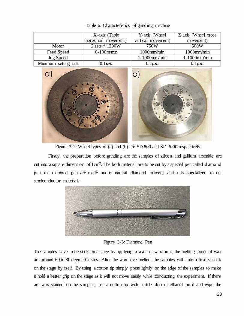
Firstly, the preparation before grinding are the samples of silicon and gallium arsenide are
cut into a square dimension of 1cm2. The both material are to be cut by a special pen called diamond
pen, the diamond pen are made out of natural diamond material and it is specialized to cut
semiconductor materials.
Figure 3-3: Diamond Pen
The samples have to be stick on a stage by applying a layer of wax on it, the melting point of wax
are around 60 to 80 degree Celsius. After the wax have melted, the samples will automatically stick
on the stage by itself. By using a cotton tip simply press lightly on the edge of the samples to make
it hold a better grip on the stage as it will not move easily while conducting the experiment. If there
are wax stained on the samples, use a cotton tip with a little drip of ethanol on it and wipe the
a)
24
samples in one direction to remove the stain. The purpose of wiping off the wax stained is to
improve the accuracy of grinding without having any extra thickness contributing on the samples.
One stage could fit up to four samples with tightly spaced between one and another, and the
arrangement of the samples are placed in a vertical position which aligned with the stage.
In the process of setting up the precision grinding machine (Okamoto UPZ315Li), there
involve plenty of steps to switch on the machine. The steps of switching on the machine are taught
by my supervisor and are advised to operate with care. After the machine is switched on, the next
step is to be sure that the correct wheel are fitted on the machine otherwise it should be change.
The wheel must be in a completely stopped position to be able to start changing the wheel. It have
a specialize equipment that are designed to fit perfectly to the wheel to be unscrew and change to
the desire wheel.
Moreover, the following steps of preparation before the grinding process are balancing.
This is a procedure where it is important when conducting a high speed grinding experiment, as
the faster the wheel spin the more the wheel vibrate. The outcome of the final results will be
strongly affected by the unbalance wheel, therefore this procedure must be taken precisely in order
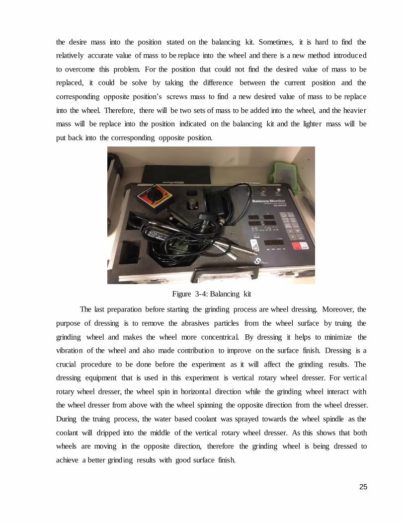
to achieve a better final results. There is a balancing kit that are used to balance the wheel, and the
procedure of operating the balancing kit were taught by my supervisor. There is a laser stand that
are connected to the balancing kit and the laser stand were being adjusted to a 45 degree angle to
accurately point the laser sensor directly to the wheel spindle. For a normal grinding wheel speed
of less than 80m/s are expected to reach 0.1 offset of wheel balance, and a minimum of 0.02 offset
for high speed grinding which is the wheel speed of 80m/s or higher. It is relatively easy for the
normal grinding wheel speed to achieve the requirement of 0.1 offset as the wheel has less vibration
when it is not operating in high speed grinding. As to achieve a minimum requirement of 0.02
offset for the high speed grinding, it is harder as the higher the wheel speed the more the unbalance
the wheel and vibration.
Besides that, when the wheel does not meet the offset requirement, a list of procedure to
balance the wheel were introduced. On the grinding wheel, there are 23 holes and the holes were
labelled with number on it as an indication of position for wheel balancing purpose. In the
procedure list, it was asked to insert a tiny screw that weigh around 0.190g into the grinding wheel
position 1. After allowing the wheel to be run for a few minutes, it is observe from the balancing
kit display screen that the value of mass should be added into which position of the wheel. After
the wheel has completely stop, retrieve the tiny screw that are inserted into position 1 and replace
25
the desire mass into the position stated on the balancing kit. Sometimes, it is hard to find the
relatively accurate value of mass to be replace into the wheel and there is a new method introduced
to overcome this problem. For the position that could not find the desired value of mass to be
replaced, it could be solve by taking the difference between the current position and the
corresponding opposite position’s screws mass to find a new desired value of mass to be replace
into the wheel. Therefore, there will be two sets of mass to be added into the wheel, and the heavier
mass will be replace into the position indicated on the balancing kit and the lighter mass will be
put back into the corresponding opposite position.
Figure 3-4: Balancing kit
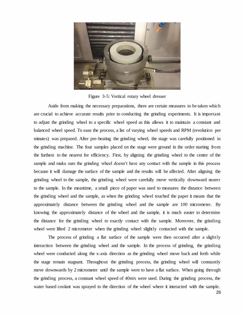
The last preparation before starting the grinding process are wheel dressing. Moreover, the
purpose of dressing is to remove the abrasives particles from the wheel surface by truing the
grinding wheel and makes the wheel more concentrical. By dressing it helps to minimize the
vibration of the wheel and also made contribution to improve on the surface finish. Dressing is a
crucial procedure to be done before the experiment as it will affect the grinding results. The
dressing equipment that is used in this experiment is vertical rotary wheel dresser. For vertical
rotary wheel dresser, the wheel spin in horizontal direction while the grinding wheel interact with
the wheel dresser from above with the wheel spinning the opposite direction from the wheel dresser.
During the truing process, the water based coolant was sprayed towards the wheel spindle as the
coolant will dripped into the middle of the vertical rotary wheel dresser. As this shows that both
wheels are moving in the opposite direction, therefore the grinding wheel is being dressed to
achieve a better grinding results with good surface finish.
26
Figure 3-5: Vertical rotary wheel dresser
Aside from making the necessary preparations, there are certain measures to be taken which
are crucial to achieve accurate results prior to conducting the grinding experiments. It is important
to adjust the grinding wheel to a specific wheel speed as this allows it to maintain a constant and
balanced wheel speed. To ease the process, a list of varying wheel speeds and RPM (revolution per
minutes) was prepared. After pre-heating the grinding wheel, the stage was carefully positioned in
the grinding machine. The four samples placed on the stage were ground in the order starting from
the furthest to the nearest for efficiency. First, by aligning the grinding wheel to the center of the
sample and make sure the grinding wheel doesn’t have any contact with the sample in this process
because it will damage the surface of the sample and the results will be affected. After aligning the
grinding wheel to the sample, the grinding wheel were carefully move vertically downward nearer
to the sample. In the meantime, a small piece of paper was used to measures the distance between
the grinding wheel and the sample, as when the grinding wheel touched the paper it means that the
approximately distance between the grinding wheel and the sample are 100 micrometer. By
knowing the approximately distance of the wheel and the sample, it is much easier to determine
the distance for the grinding wheel to exactly contact with the sample. Moreover, the grinding
wheel were lifted 2 micrometer when the grinding wheel slightly contacted with the sample.
The process of grinding a flat surface of the sample were then occurred after a slightly
interaction between the grinding wheel and the sample. In the process of grinding, the grinding
wheel were conducted along the x-axis direction as the grinding wheel move back and forth while
the stage remain stagnant. Throughout the grinding process, the grinding wheel will constantly
move downwards by 2 micrometer until the sample were to have a flat surface. When going through
the grinding process, a constant wheel speed of 40m/s were used. During the grinding process, the
water based coolant was sprayed to the direction of the wheel where it interacted with the sample.
27
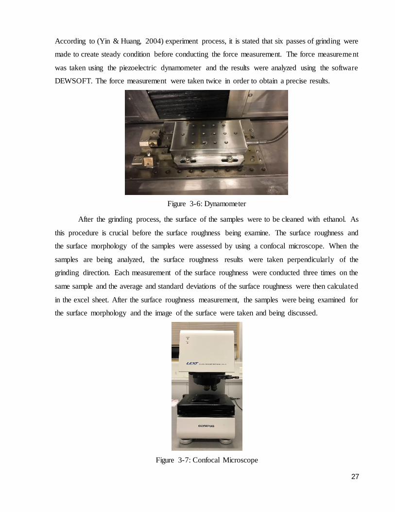
According to (Yin & Huang, 2004) experiment process, it is stated that six passes of grinding were
made to create steady condition before conducting the force measurement. The force measurement
was taken using the piezoelectric dynamometer and the results were analyzed using the software
DEWSOFT. The force measurement were taken twice in order to obtain a precise results.
Figure 3-6: Dynamometer
After the grinding process, the surface of the samples were to be cleaned with ethanol. As
this procedure is crucial before the surface roughness being examine. The surface roughness and
the surface morphology of the samples were assessed by using a confocal microscope. When the
samples are being analyzed, the surface roughness results were taken perpendicularly of the
grinding direction. Each measurement of the surface roughness were conducted three times on the
same sample and the average and standard deviations of the surface roughness were then calculated
in the excel sheet. After the surface roughness measurement, the samples were being examined for
the surface morphology and the image of the surface were taken and being discussed.
Figure 3-7: Confocal Microscope
28
4.0 Results and discussions
4.1 Effect of depth of cut
The following results were obtained during the experiment and the results were being analyzed
using the software DEWSOFT. After the results being analyzed, the data was tabulated in an excel
sheet and plotted on a graph. The section below discuss the results of force applied on the material
during grinding process, the surface roughness of the material, and the surface morphology
obtained from the confocal microscope.
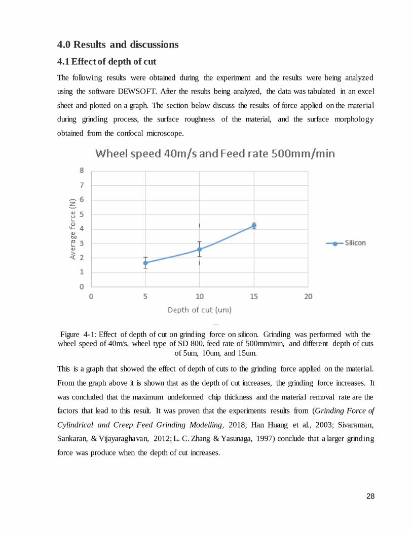
Figure 4-1: Effect of depth of cut on grinding force on silicon. Grinding was performed with the wheel speed of 40m/s, wheel type of SD 800, feed rate of 500mm/min, and different depth of cuts
of 5um, 10um, and 15um.
This is a graph that showed the effect of depth of cuts to the grinding force applied on the material.
From the graph above it is shown that as the depth of cut increases, the grinding force increases. It
was concluded that the maximum undeformed chip thickness and the material removal rate are the
factors that lead to this result. It was proven that the experiments results from (Grinding Force of
Cylindrical and Creep Feed Grinding Modelling, 2018; Han Huang et al., 2003; Sivaraman,
Sankaran, & Vijayaraghavan, 2012; L. C. Zhang & Yasunaga, 1997) conclude that a larger grinding
force was produce when the depth of cut increases.
29
4.2 Effect of feed rate
Figure 4-2: Effect of feed rate on grinding force on silicon. Grinding was performed with the wheel speed of 60m/s, wheel type of SD 3000, depth of cut of 10um, with different feed rates of
250mm/min, 500mm/min, and 1000mm/min.
From the graph above it shows the grinding force as a function of feed rate with the material silicon.
The results show that with the increasing in feed rates, the grinding force increases as well. As
observed from the increasing of feed rate from 500mm/min to 1000mm/min, the grinding force
slightly increases compared to the feed rate from 250mm/min to 500mm/min. It can be concluded
that by performing a higher table speed, the surface contact between the wheel and the material is
lesser, therefore the grinding force is increasing slowly from feed rates of 500mm/min to
1000mm/min. It is also proven from the experiment results from (Grinding Force of Cylindrical
and Creep Feed Grinding Modelling, 2018; Han Huang et al., 2003; A. Kumar, Ghosh, &
Aravindan, 2017; Sivaraman et al., 2012) that the grinding force increased double when the feed
rates increased from 200mm/min to 1000mm/min compared to 500mm/min to 1000mm/min. By
performing a higher feed rate result in decreasing the grinding force owing to the wheel of speed
increases (Han Huang et al., 2003).
30
Figure 4-3: Effect of feed rates on surface roughness on silicon. Grinding was performed with the wheel speed of 60m/s, wheel type of SD 3000, depth of cut of 10um, with different feed rates of
250mm/min, 500mm/min, and 1000mm/min.
From the graph above it shows that a silicon with a depth of cut of 10um plotting against different
feed rates and surface roughness. As observed from the increasing of feed rate from 250mm/min
to 1000mm/min, the surface roughness increases linearly. The surface roughness generally getting
worse with each increase of feed rates. It can be concluded that by performing a higher table speed,
the surface roughness will get worst. From the experiment results of (Tao et al., 2017) has shown
that in increasing of feed rates will result in having bad outcome on the surface roughness. It is
because by increasing feed rates, it might add loads to each abrasives cut. From the studies of (Han
Huang et al., 2003) it is proven that there is a large elevation for the surface roughness by reducing
the feed rate from 1000mm/min to 500mm/min, where there is only a small changes of surface
roughness when reducing the feed rates from 500mm/min to 200mm/min.
31
4.3 Effect of wheel speed
Figure 4-4: Effect of wheel speed on grinding force on silicon. Grinding was performed with the wheel type of SD 800, feed rate of 500mm/min, depth of cut of 10um, with different wheel speed
of 40m/s, 60m/s, and 80m/s.
The graph above shown the silicon plotted against the grinding force and different wheel speeds.
It is shown in the graph that the grinding force decreases when the wheel speed increases. This
scenario is related to the maximum undeformed chip thickness and the material removal rate. It
can be explain that when the maximum undeformed chip thickness is smaller than the critical depth
of cut then the material will occur ductile transition. As proven from the experiments from
(Grinding Force of Cylindrical and Creep Feed Grinding Modelling, 2018; Han Huang et al., 2003;
A. Kumar et al., 2017; Singleton, 2012; Sivaraman et al., 2012; Zhu, Yan, & Li, 2014) that a small
undeformed chip thickness will achieved with increasing the wheel speed, and it will result to
achieve a smaller grinding force.
32
Figure 4-5: Effect of wheel speed on surface roughness on silicon. Grinding was performed with
the wheel type of SD 800, feed rate of 500mm/min, with different depth of cuts of 5um, 10um, and 15um, and different wheel speed of 40m/s, 60m/s, and 80m/s.
The graph above shows the surface roughness as a function of wheel speed with different depth of
cuts. From the results shown in the graph above that the surface roughness increases when the
wheel speed increases. As the result achieved from this experiment does not satisfy the theory of
high speed grinding. The surface roughness will become finer with the increase of wheel speed,
but as shown in the graph above that with the highest wheel speed which have achieve high speed
grinding, the surface roughness increases which means that the surface turns bad. As proven from
the experiment of (Zhu et al., 2014) that by increasing the wheel speed will result in enlarging the
material removal rate and the surface roughness will improve owing to the increase of wheel speed.
The error results performed in the graph above could address to the factor of not dressing the
grinding wheel properly as the abrasive are not completely removed from the grinding wheel which
contributed in increasing the surface roughness. Another factor that could lead to this result is
vibration of the wheel, vibration caused by wheel imbalance at higher speed could worsen the
surface quality as well. To mitigate this problem, in future work research the wheel must be dressed
properly with a longer time and the grinding wheel must be balance according to the actual speed.
33
4.4 Effect of types of wheel
Figure 4-6: Effect of different types of wheel on grinding force on silicon. Grinding was
performed with the wheel speed of 60m/s, feed rate of 500mm/min, depth of cut of 10um, and wheel types of SD 800 and SD 3000.
The graph above shows the relations of grinding force and different types of wheel. As observed,
the wheel of SD 3000 achieve a higher force than the wheel of SD 800. It is proven from this graph
that smaller grit wheel will have a smaller force compare to the larger grit wheel, and it is concluded
that higher grit wheel will have higher grit wear. From the experiment of ("The Effect of Grinding
on grinding Wheel Condition," 2006; L. C. Zhang & Yasunaga, 1997) it can strongly support that
the conclusion that have been made towards this graph is reasonable. Besides that, it is proven from
the("The Effect of Grinding on grinding Wheel Condition," 2006), with smaller grit wheel the
cutting grit rates will drop with time which affected by a large number of grit being wear off.
34
Figure 4-7: Effect of depth of cut on surface roughness of silicon. Grinding was performed with the wheel speed of 60m/s, feed rate of 500mm/min, wheel types of SD 800 and SD 3000, and
with different depth of cuts of 5um, 10um, and 15um.
The graph above aims to compare the surface roughness with different types of grinding wheel
applied in the experiment. Ra was performed as an output measurement for surface roughness, as
it is commonly used in an aerospace sector. From the experiment outcome that have been concluded
by (Z. Zhang et al., 2011) that there was a small variation in surface roughness between the
sample’s chip thickness. It is clearly shown in the graph that the surface roughness obtained from
SD 800 are larger than SD 3000. From this experiment it is proven that with rougher grit wheel
will result in removing more materials and produce a rougher surface finish, while with a finer grit
wheel will result in removing lesser material and produce a smoother finish. Therefore, it is shown
that by using the wheel of SD 3000 improves the surface roughness compare to the wheel of SD
800. The effect of grain size will strongly influence the surface roughness of the material, as the
smaller grain size wheel it improve the surface roughness of the material compared to the larger
grain size wheel (Wang & etc, 1999). It is safe to assume that the surface roughness slightly
increases owning to the increase of depth of cuts in each wheel.
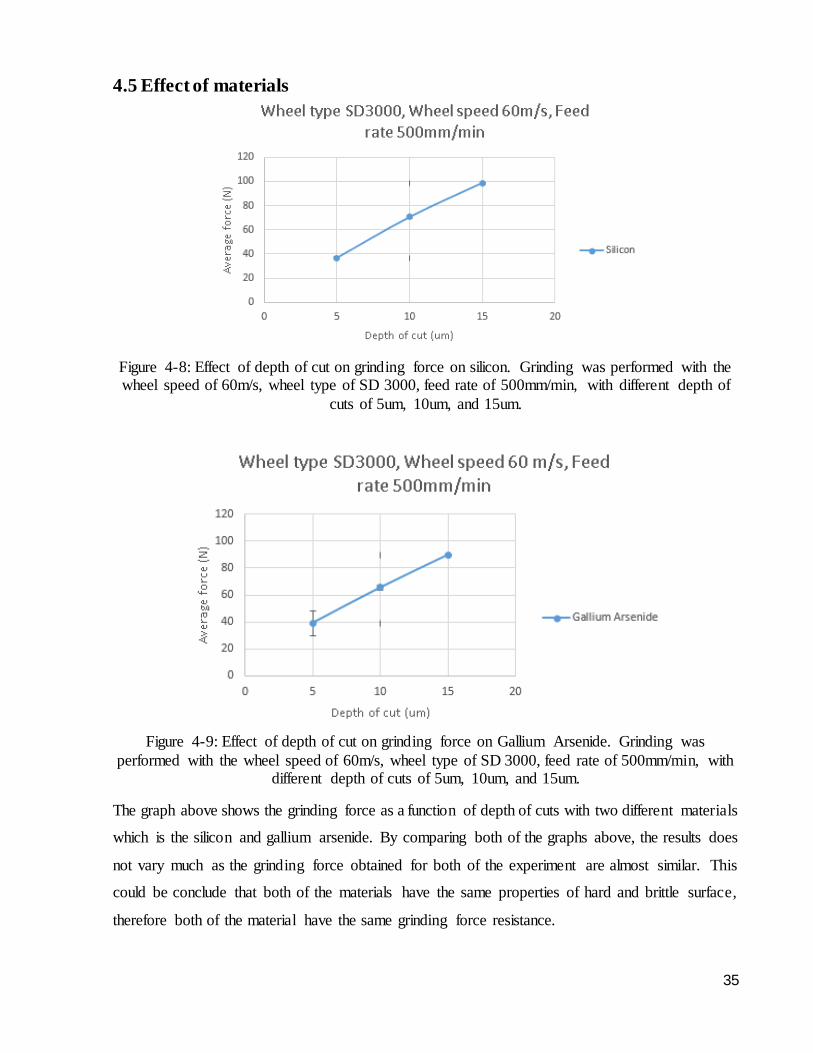
35
4.5 Effect of materials
Figure 4-8: Effect of depth of cut on grinding force on silicon. Grinding was performed with the wheel speed of 60m/s, wheel type of SD 3000, feed rate of 500mm/min, with different depth of
cuts of 5um, 10um, and 15um.
Figure 4-9: Effect of depth of cut on grinding force on Gallium Arsenide. Grinding was
performed with the wheel speed of 60m/s, wheel type of SD 3000, feed rate of 500mm/min, with different depth of cuts of 5um, 10um, and 15um.
The graph above shows the grinding force as a function of depth of cuts with two different materials
which is the silicon and gallium arsenide. By comparing both of the graphs above, the results does
not vary much as the grinding force obtained for both of the experiment are almost similar. This
could be conclude that both of the materials have the same properties of hard and brittle surface,
therefore both of the material have the same grinding force resistance.
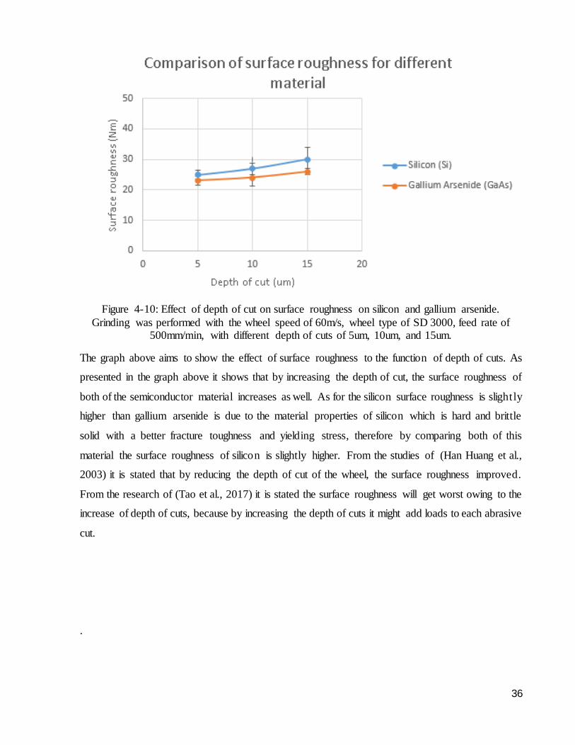
36
Figure 4-10: Effect of depth of cut on surface roughness on silicon and gallium arsenide.
Grinding was performed with the wheel speed of 60m/s, wheel type of SD 3000, feed rate of 500mm/min, with different depth of cuts of 5um, 10um, and 15um.
The graph above aims to show the effect of surface roughness to the function of depth of cuts. As
presented in the graph above it shows that by increasing the depth of cut, the surface roughness of
both of the semiconductor material increases as well. As for the silicon surface roughness is slightly
higher than gallium arsenide is due to the material properties of silicon which is hard and brittle
solid with a better fracture toughness and yielding stress, therefore by comparing both of this
material the surface roughness of silicon is slightly higher. From the studies of (Han Huang et al.,
2003) it is stated that by reducing the depth of cut of the wheel, the surface roughness improved.
From the research of (Tao et al., 2017) it is stated the surface roughness will get worst owing to the
increase of depth of cuts, because by increasing the depth of cuts it might add loads to each abrasive
cut.
.
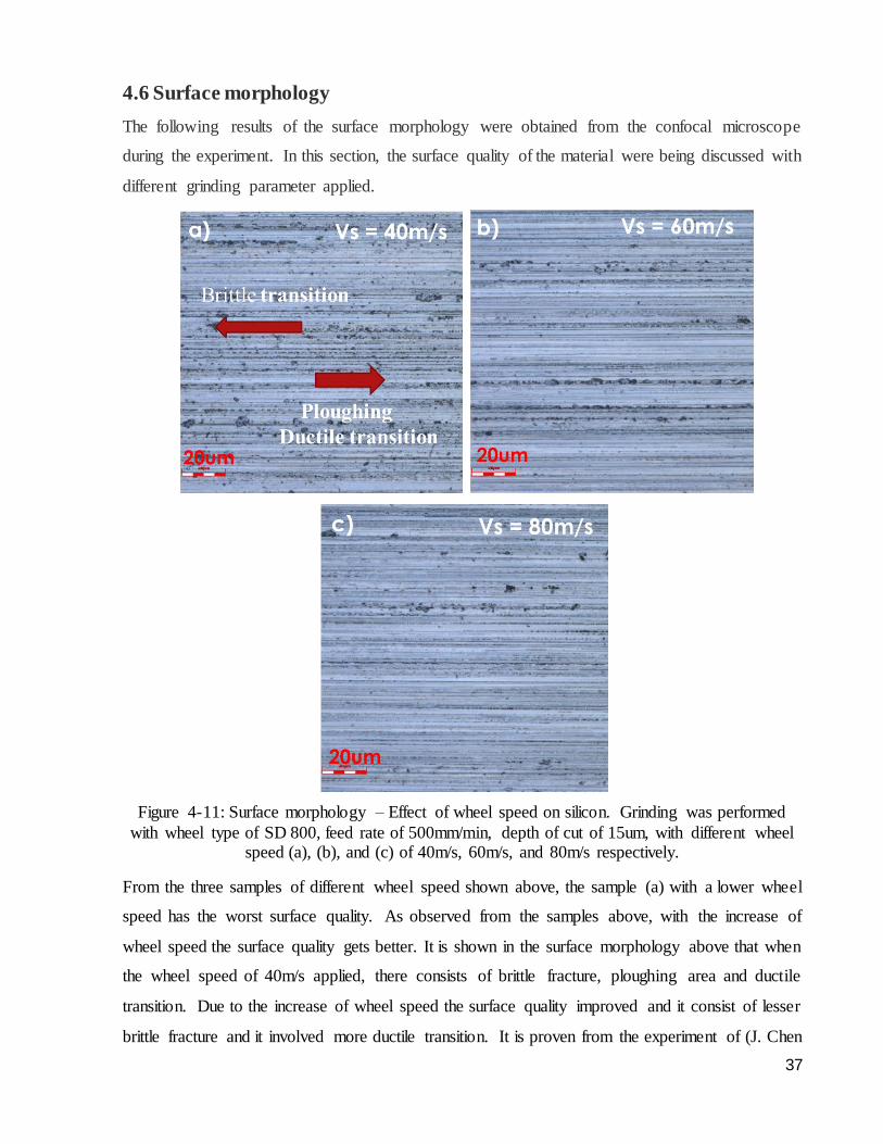
37
4.6 Surface morphology
The following results of the surface morphology were obtained from the confocal microscope
during the experiment. In this section, the surface quality of the material were being discussed with
different grinding parameter applied.
Figure 4-11: Surface morphology – Effect of wheel speed on silicon. Grinding was performed
with wheel type of SD 800, feed rate of 500mm/min, depth of cut of 15um, with different wheel speed (a), (b), and (c) of 40m/s, 60m/s, and 80m/s respectively.
From the three samples of different wheel speed shown above, the sample (a) with a lower wheel
speed has the worst surface quality. As observed from the samples above, with the increase of
wheel speed the surface quality gets better. It is shown in the surface morphology above that when
the wheel speed of 40m/s applied, there consists of brittle fracture, ploughing area and ductile
transition. Due to the increase of wheel speed the surface quality improved and it consist of lesser
brittle fracture and it involved more ductile transition. It is proven from the experiment of (J. Chen
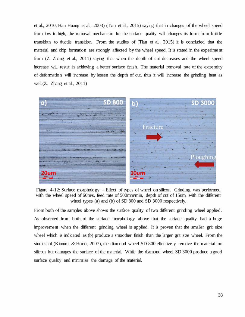
38
et al., 2010; Han Huang et al., 2003) (Tian et al., 2015) saying that in changes of the wheel speed
from low to high, the removal mechanism for the surface quality will changes its form from brittle
transition to ductile transition. From the studies of (Tian et al., 2015) it is concluded that the
material and chip formation are strongly affected by the wheel speed. It is stated in the experiment
from (Z. Zhang et al., 2011) saying that when the depth of cut decreases and the wheel speed
increase will result in achieving a better surface finish. The material removal rate of the extremity
of deformation will increase by lessen the depth of cut, thus it will increase the grinding heat as
well.(Z. Zhang et al., 2011)
Figure 4-12: Surface morphology – Effect of types of wheel on silicon. Grinding was performed with the wheel speed of 60m/s, feed rate of 500mm/min, depth of cut of 15um, with the different
wheel types (a) and (b) of SD 800 and SD 3000 respectively.
From both of the samples above shows the surface quality of two different grinding wheel applied .
As observed from both of the surface morphology above that the surface quality had a huge
improvement when the different grinding wheel is applied. It is proven that the smaller grit size
wheel which is indicated as (b) produce a smoother finish than the larger grit size wheel. From the
studies of (Kimura & Horio, 2007), the diamond wheel SD 800 effectively remove the material on
silicon but damages the surface of the material. While the diamond wheel SD 3000 produce a good
surface quality and minimize the damage of the material.
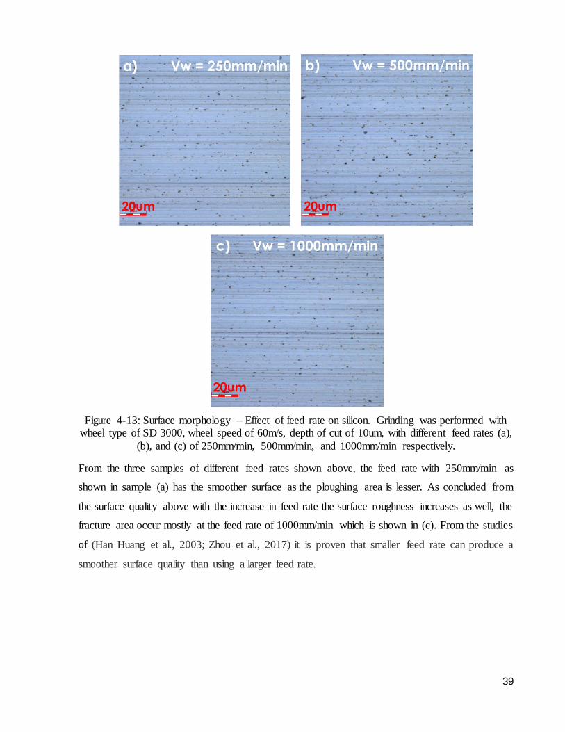
39
Figure 4-13: Surface morphology – Effect of feed rate on silicon. Grinding was performed with wheel type of SD 3000, wheel speed of 60m/s, depth of cut of 10um, with different feed rates (a),
(b), and (c) of 250mm/min, 500mm/min, and 1000mm/min respectively.
From the three samples of different feed rates shown above, the feed rate with 250mm/min as
shown in sample (a) has the smoother surface as the ploughing area is lesser. As concluded from
the surface quality above with the increase in feed rate the surface roughness increases as well, the
fracture area occur mostly at the feed rate of 1000mm/min which is shown in (c). From the studies
of (Han Huang et al., 2003; Zhou et al., 2017) it is proven that smaller feed rate can produce a
smoother surface quality than using a larger feed rate.
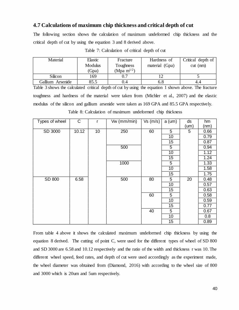
40
4.7 Calculations of maximum chip thickness and critical depth of cut
The following section shows the calculation of maximum undeformed chip thickness and the
critical depth of cut by using the equation 3 and 8 derived above.
Table 7: Calculation of critical depth of cut
Material Elastic
Modulus (Gpa)
Fracture
Toughness (Mpa m1/2)
Hardness of
material (Gpa)
Critical depth of
cut (nm)
Silicon 169 0.7 12 5
Gallium Arsenide 85.5 0.4 6.8 4.4
Table 3 shows the calculated critical depth of cut by using the equation 1 shown above. The fracture
toughness and hardness of the material were taken from (Michler et al., 2007) and the elastic
modulus of the silicon and gallium arsenide were taken as 169 GPA and 85.5 GPA respectively.
Table 8: Calculation of maximum undeformed chip thickness
Types of wheel C r Vw (mm/min) Vs (m/s) a (um) ds (um)
hm (nm)
SD 3000 10.12 10 250 60 5 5 0.66
10 0.79
15 0.87
500 5 0.94
10 1.12
15 1.24
1000 5 1.33
10 1.58
15 1.75
SD 800 6.58 500 80 5 20 0.48
10 0.57
15 0.63
60 5 0.58
10 0.59
15 0.77
40 5 0.67
10 0.8
15 0.89
From table 4 above it shows the calculated maximum undeformed chip thickness by using the
equation 8 derived. The cutting of point C, were used for the different types of wheel of SD 800
and SD 3000 are 6.58 and 10.12 respectively and the ratio of the width and thickness r was 10. The
different wheel speed, feed rates, and depth of cut were used accordingly as the experiment made,
the wheel diameter was obtained from (Diamond, 2016) with according to the wheel size of 800
and 3000 which is 20um and 5um respectively.
41
5.0 Conclusion
Semiconductor materials like silicon and gallium arsenide have a material properties of
hard hardness and brittleness, most of the semiconductor materials will achieve brittle fracture
transition unless they are undergoing the machining technics especially grinding process. In
conclusion, the studies of precision grinding of semiconductor shows various possible outcomes to
the grinding process. It is concluded that high speed grinding have taken advantages in the grinding
process. From the experiment results shown in the discussion, semiconductors like silicon and
gallium arsenide with a material properties of hard hardness and brittleness, by performing high
speed grinding on the semiconductors it can achieve ductile transition. High speed grinding helps
to improve the surface roughness, surface quality, and decreases the grinding force when the
grinding wheel speed were increased. It can be concluded that the grinding force and surface
roughness increased with the increase of depth of cut and feed rate. Other than that, the surface
roughness will achieve smoother surface when the wheel speed reaches a higher speed. Besides
that, the grinding force decreases when the wheel speed increases. This could be explain by the
maximum undeformed chip thickness, with the increases of wheel speed the maximum undeformed
chip thickness will be smaller, therefore the grinding force will be lesser as well. In the application
of maximum undeformed chip thickness lesser than the critical depth of cut, then the surface quality
will occur ductile transition. While the maximum undeformed chip thickness is larger than the
critical depth of cut, the surface quality will occur brittle fracture transition. Moreover, two
different types of wheel were performed in the experiment which are the wheel type of SD 800 and
SD 3000. With two different types of wheel conducted in the experiment, it is concluded that the
rougher grit size wheel will remove more material and result in a rougher surface finish, while the
finer grit size wheel will remove lesser material but will provide a smoother finish. From the results
discussed, SD 800 with a larger grit wheel size will produce larger force while the SD 3000 with
smaller grit wheel size will have a smaller force. As observed from the surface morphology, with
the wheel speed of 40m/s the surface quality consist of brittle and ductile transition, and when the
wheel speed approached high speed grinding the surface quality improved and achieve ductile
transition. However, wheel type of SD 3000 produce a better surface quality compared to wheel
type of SD 800, as the surface quality of SD 3000 are more to ductile transition and smoother
surface. Next, it is shown in the surface morphology that the surface quality are getting rougher
when the feed rate increases. It is concluded that, by increasing the feed rate and depth of cut the
surface quality will become rougher, while with the increase of wheel speed the surface quality

42
achieve a smoother surface. On top of that, it is concluded that the grinding force are effective ly
influenced by the depth of cut follow by the wheel speed and then the feed rates. Overall, it is
concluded that high speed grinding are a very effective grinding process and it optimize cost for
the machining and grinding process as well.
43
6.0 Future work
During the experiment, there are several experiment errors occurred and due to the
insufficient time limitation to complete the experiment progress. There are a few possible ways
that could improve the efficiency and achieving a precise results in the future work. In the future
work, by conducting more experiments with different parameters could achieve a more precise and
accurate data. In one of the experiment result shown above, the results was being affected owing
to the insufficient time of dressing the wheel and it leads to an inaccurate results, and therefore, in
the future work the wheel must be dressed desirably in order to achieve a better surface finish and
surface quality. Lastly, the surface morphology obtained by using the wheel type of SD 3000 were
not clearly shown much difference in comparison of feed rates. In the future work, with using a
finer grit wheel in comparison with the wheel type of SD 3000 would possibly provide a better
surface quality and surface finish in the surface morphology.
44
7.0 References
Agarwal, S., & Venkateswara Rao, P. (2010). Grinding characteristics, material removal and
damage formation mechanisms in high removal rate grinding of silicon carbide. International Journal of Machine Tools and Manufacture, 50(12), 1077-1087.
doi:10.1016/j.ijmachtools.2010.07.006 Atlantic Euipment Engineers, D. o. M. (Producer). (2013, MAY 27). Gallium Arsenide (GaAs)
Semiconductors. AZO MATERIALS. Retrieved from
https://www.azom.com/article.aspx?ArticleID=8349 Bifano, T., Dow, T., & Scattergood, R. (1991). Ductile-Regime Grinding: a New Technology for
Machining Brittle Materials. Journal of Engineering for Industry (Transactions of the ASME), 113(2), 184-189. doi:10.1115/1.2899676
Buschow, K. H. J., Flemings, M. C., & Cahn, R. (2001). The Encyclopedia of Materials : Science
and Technology. Place of publication not identified: Pergamon Imprint. Chen, J., Shen, J., Huang, H., & Xu, X. (2010). Grinding characteristics in high speed grinding of
engineering ceramics with brazed diamond wheels. Journal of Materials Processing Tech, 210(6), 899-906. doi:10.1016/j.jmatprotec.2010.02.002
Chen, S. (2018). Modelling and simulation of nano-surface generation in ultra-precision grinding.
In: The Hong Kong Polytechnic University. Dai, J., Su, H., Yu, T., Hu, H., Zhou, W., & Ding, W. (2018). Experimental investigation on
materials removal mechanism during grinding silicon carbide ceramics with single diamond grain. Precision Engineering, 51, 271-279. doi:10.1016/j.precisioneng.2017.08.019
Diamond, Y. A. (Producer). (2016, May 1). Diamond & CBN Wheels. Asahi Diamond. Retrieved from https://www.asahidia.co.jp/eng/wp-content/uploads/2015/05/B02.pdf
Dornfeld, D., & Lee, D.-E. (2008). Precision Manufacturing. Boston, MA: Springer US. The Effect of Grinding on grinding Wheel Condition. (2006). MichiganTech. Retrieved from
http://www.michigantech.com
Green, P. E. D. H. (2019). Temperature Dependence of Semiconductor Conductivity. Retrieved from San Jose:
Grinding Force of Cylindrical and Creep Feed Grinding Modelling. (2018). London: IntechOpen. Grinding Technology. (2008). SME. Huang, H. (2003). Machining characteristics and surface integrity of yttria stabilized tetragonal
zirconia in high speed deep grinding. Materials Science & Engineering A, 345(1), 155-163. doi:10.1016/S0921-5093(02)00466-5
Huang, H., & Liu, Y. C. (2003). Experimental investigations of machining characteristics and removal mechanisms of advanced ceramics in high speed deep grinding. International Journal of Machine Tools and Manufacture, 43(8), 811-823. doi:10.1016/S0890-
6955(03)00050-6 Huang, H., Yin, L., & Zhou, L. (2003). High speed grinding of silicon nitride with resin bond
diamond wheels. Journal of Materials Processing Tech, 141(3), 329-336. doi:10.1016/S0924-0136(03)00284-X
Jackson, M. J., & Davim, J. P. (2011). Machining with Abrasives (1st ed. 2011.. ed.). New York,
NY: Springer US : Imprint: Springer. Jahanmir, S., Ramulu, M., & Koshy, P. (1999). Machining of ceramics and composites. New York:
Marcel Dekker.
45
Kimura, F., & Horio, K. (2007). Towards Synthesis of Micro-/Nano-systems: The 11th International Conference on Precision Engineering (ICPE) August 16–18, 2006, Tokyo, Japan. London: Springer London.
Klocke, F., Brinksmeier, E., Evans, C., Howes, T., Lnasaki, I., Minke, E., . . . Stuff, D. (1997). High-Speed Grinding-Fundamentals and State of the Art in Europe, Japan, and the USA.
CIRP Annals - Manufacturing Technology, 46(2), 715-724. doi:10.1016/S0007-8506(07)91100-2
Kumar, A., Ghosh, S., & Aravindan, S. (2017). Grinding performance improvement of silicon
nitride ceramics by utilizing nanofluids. Ceramics International, 43(16), 13411-13421. doi:10.1016/j.ceramint.2017.07.044
Kumar, S., & Dhanabalan, S. (2018). A Review of Cylindrical Grinding Process parameters by using various Optimization techniques and their effects on the surface Integrity, Wear Rate and MRR.
Landry, C. C., & Barron, A. R. (1993). Synthesis of Polycrystalline Chalcopyrite Semiconduc tors by Microwave Irradiation. Science, 260(5114), 1653-1655.
doi:10.1126/science.260.5114.1653 Lawn, B., Jensen, T., & Arora, A. (1976). Brittleness as an indentation size effect. Journal of
Materials Science, 11(3), 573-575. doi:10.1007/BF00540940
Li, B., Ni, J., Yang, J., & Liang, S. Y. (2014). Study on high-speed grinding mechanisms for quality and process efficiency.(Report). The International Journal of Advanced Manufacturing
Technology, 70(5-8), 813. doi:10.1007/s00170-013-5297-y Li, J., Fang, Q., Zhang, L., & Liu, Y. (2015). Subsurface damage mechanism of high speed grinding
process in single crystal silicon revealed by atomistic simulations. Applied Surface Science,
324, 464-474. doi:10.1016/j.apsusc.2014.10.149 Liang, S., & Shih, A. J. (2016). Analysis of Machining and Machine Tools (1st ed. 2016.. ed.). New
York, NY: Springer US : Imprint: Springer. Liang, Z., Wang, X., Wu, Y., Xie, L., Liu, Z., & Zhao, W. (2012). An investigation on wear
mechanism of resin-bonded diamond wheel in Elliptical Ultrasonic Assisted Grinding
(EUAG) of monocrystal sapphire. Journal of Materials Processing Tech, 212(4), 868-876. doi:10.1016/j.jmatprotec.2011.11.009
Liao, T. W., Li, K., & McSpadden, S. B. (2000). Wear mechanisms of diamond abrasives during transition and steady stages in creep-feed grinding of structural ceramics. Wear, 242(1), 28-37. doi:10.1016/S0043-1648(00)00366-5
Michler, J., Wasmer, K., Meier, S., Östlund, F., & Leifer, K. (2007). Plastic deformation of gallium arsenide micropillars under uniaxial compression at room temperature. Applied Physics
Letters, 90(4). doi:10.1063/1.2432277 N, V., Hung, L., Tung, L., & Long, B. (2016). Cost Optimization of Internal Grinding. Journal of
Materials Science and Engineering B, 6. doi:10.17265/2161-6221/2016.11-12.004
Opoz, T. (2012). Investigation of material removal mechanism in grinding: a single grit approach. In: ProQuest Dissertations Publishing.
Pei, Z. J., Fisher, G. R., & Liu, J. (2008). Grinding of silicon wafers: A review from historica l perspectives. International Journal of Machine Tools and Manufacture, 48(12-13), 1297-1307. doi:10.1016/j.ijmachtools.2008.05.009
Petersen, K. E. (1982). Silicon as a mechanical material. Proceedings of the IEEE, 70(5), 420-457. doi:10.1109/PROC.1982.12331
Petukhov, B. (2004). A theory of the effect of impurities on the yield stress of silicon crystals. Semiconductors, 38(4), 369-375. doi:10.1134/1.1734660
Rowe, W. B. (2010). Modern grinding techniques. Salem, Mass. : Hoboken, NJ: Scrivener
46
Wiley. Rowe, W. B. (2014). Principles of modern grinding technology (2nd ed.. ed.). Amsterdam:
Elsevier/William Andrew.
Samar (Producer). (2011). Surface & Cylindrical Grinding. Samar Precision Engineering. Retrieved from http://www.samarprecisioneng.co.uk/Surface-Cylindrical-Grinding.html
Schneider, G. (Producer). (2011, February 16). Chapter 17: Cutting Tool Applications - Grinding Methods and Machines. AMERICAN MACHINIST. Retrieved from https://www.americanmachinist.com/machining-cutting/chapter-17-cutting-tool-
applications-grinding-methods-and-machines Shimada, S., Inamura, T., & Ikawa, N. (1997). Advances In Abrasive Technology: World Scientific
Publishing Co. Pte. Ltd. Shu, W. (2015). Study of silicon substrate properties at mm-wave and THz frequencies and their
impact on passive and active devices. In R. M. Henderson, H. S. Shichijo, R. Henderson,
D. MacFarlane, K. O, & H. Shichijo (Eds.): ProQuest Dissertations Publishing. Singleton, R. (2012). Utilisation of chip thickness models in grinding. In: ProQuest Dissertations
Publishing. Sivaraman, V., Sankaran, S., & Vijayaraghavan, L. (2012). The Effect of Cutting Parameters on
Cutting Force During Turning Multiphase Microalloyed Steel. Procedia CIRP, 4(C), 157-
160. doi:10.1016/j.procir.2012.10.028 Sumigawa, T., Ashida, S., Tanaka, S., Sanada, K., & Kitamura, T. (2015). Fracture toughness of
silicon in nanometer-scale singular stress field. Engineering Fracture Mechanics, 150, 161-167. doi:10.1016/j.engfracmech.2015.05.054
Sze, S. M. (2007). Physics of semiconductor devices, third edition (3rd ed ed.). Hoboken, N.J.:
Wiley-Interscience. Takenaka, N., & Sasaya, S. (1966). Research on the Grinding Action by Single Grit (2nd Report).
Transactions of the Japan Society of Mechanical Engineers, 32(237), 811-815. doi:10.1299/kikai1938.32.811
Tao, Z., Yaoyao, S., Laakso, S., & Jinming, Z. (2017). Investigation of the Effect of Grinding
Parameters on Surface Quality in Grinding of TC4 Titanium Alloy. In (Vol. 11, pp. 2131-2138): Elsevier B.V.
Tian, L., Fu, Y., Xu, J., Li, H., & Ding, W. (2015). The influence of speed on material removal mechanism in high speed grinding with single grit. International Journal of Machine Tools and Manufacture, 89, 192-201. doi:10.1016/j.ijmachtools.2014.11.010
Wang, J., & etc. (1999). Abrasive technology: current development and applications i - proceedings of the third international conference on abrasive technology (abtec '99)
(illustrated edition ed.): World Scientific Pub Co Pte. Winter, M. (2016). Eco-efficiency of Grinding Processes and Systems (1st ed. 2016.. ed.). Cham:
Springer International Publishing : Imprint: Springer.
Xu, H. H. K., Jahanmir, S., Ives, L. K., Job, L. S., & Ritchie, K. T. (1996). Short‐Crack Toughness and Abrasive Machining of Silicon Nitride. Journal of the American Ceramic Society,
79(12), 3055-3064. doi:10.1111/j.1151-2916.1996.tb08077.x Yin, L., & Huang, H. (2004). Ceramic Response to High Speed Grinding. Machining Science and
Technology, 8(1), 21-37. doi:10.1081/MST-120034240 Yin, L., Huang, H., Ramesh, K., & Huang, T. (2005). High speed versus conventional grinding in
high removal rate machining of alumina and alumina–titania. International Journal of
Machine Tools and Manufacture, 45(7), 897-907. doi:10.1016/j.ijmachtools.2004.10.016
47
Young, H. T., Liao, H.-T., & Huang, H.-Y. (2007). Novel method to investigate the critical depth of cut of ground silicon wafer. Journal of Materials Processing Tech, 182(1), 157-162. doi:10.1016/j.jmatprotec.2006.07.025
Zeng, W. M., Li, Z. C., Pei, Z. J., & Treadwell, C. (2005). Experimental observation of tool wear in rotary ultrasonic machining of advanced ceramics. International Journal of Machine
Tools and Manufacture, 45(12), 1468-1473. doi:10.1016/j.ijmachtools.2005.01.031
Zhang, H., López‐Honorato, E., Javed, A., Shapiro, I., & Xiao, P. (2012). A Study of the
Microstructure and Vickers Indentation Fracture Toughness of Silicon Carbide Coatings on TRISO Fuel Particles. Journal of the American Ceramic Society, 95(3), 1086-1092.
doi:10.1111/j.1551-2916.2011.05044.x Zhang, L. C., & Yasunaga, N. (1997). Advances in abrasive technology proceedings of the
International Symposium : Sydney, Australia, 8-10 July 1997. Singapore
River Edge, N.J.: World Scientific Pub. Co. Zhang, Z., Huo, F., Wu, Y., & Huang, H. (2011). Grinding of silicon wafers using an ultrafine
diamond wheel of a hybrid bond material. International Journal of Machine Tools and Manufacture, 51(1), 18-24. doi:10.1016/j.ijmachtools.2010.10.006
Zhou, H., Guo, M., & Wang, X. (2017). Ultraprecision grinding of silicon wafers using a newly
developed diamond wheel. Materials Science in Semiconductor Processing, 68, 238-244. doi:10.1016/j.mssp.2017.06.031
Zhu, D., Yan, S., & Li, B. (2014). Single-grit modeling and simulation of crack initiation and propagation in SiC grinding using maximum undeformed chip thickness. Computational Materials Science, 92, 13-21. doi:10.1016/j.commatsci.2014.05.019
Copyright © 2022 FDOKUMEN