
Operating manual for Grinding machine SMD 133 DRE
69
OPERATING MANUAL GRINDING MACHINE SMD 133 DRE SMD 133 DRE-60 EN LISSMAC Maschinenbau GmbH Lanzstraße 4 D-88410 Bad Wurzach Telephone +49 (0) 7564 / 307 - 0 Fax +49 (0) 7564 / 307 - 500 [email protected] www.lissmac.com METAL PROCESSING
-
Upload
khangminh22 -
Category
Documents
-
view
0 -
download
0
Transcript of Operating manual for Grinding machine SMD 133 DRE

OPERATING MANUAL GRINDING MACHINE SMD 133 DRE SMD 133 DRE-60
EN
LISSMAC Maschinenbau GmbH Lanzstraße 4 D-88410 Bad WurzachTelephone +49 (0) 7564 / 307 - 0 Fax +49 (0) 7564 / 307 - 500 [email protected]
METAL PROCESSING

Grinding machine SMD 133 DRE /-60 3
Imprint
Operating manual for Grinding machine SMD 133 DRE
Status: 01-2018 Translation of the original operating manual
Manufacturer:
LISSMAC Maschinenbau GmbH Lanzstraße 4 D-88410 Bad WurzachTelephone: +49 (0) 7564 / 307 - 0Fax: + 49 (0) 7564 / 307 - 500E-mail: [email protected]: www.lissmac.com
The dissemination or duplication of this operating manual and the reuse or disclosure of its contents are forbidden unless explicitly permitted. Non-compliance is subject to compensation for damages. All rights reserved for the purpose of patent, utility model, or design patent registration.

Table of contents
4 Grinding machine SMD 133 DRE /-60
Table of contents
1 About this manual ........................................................................................ 6
1.1 Target group .......................................................................................... 6
1.2 Additional documents .............................................................................. 6
1.3 Presentation of warnings .......................................................................... 7
1.4 Additional representations ........................................................................ 7
2 Safety ......................................................................................................... 8
2.1 Safety instructions .................................................................................. 8
2.2 Organisational measures .......................................................................... 8
2.3 Personnel selection and qualifications ......................................................... 8
2.4 Transport .............................................................................................. 9
2.5 Normal operation ................................................................................... 9
2.6 Maintenance, Service and Troubleshooting .................................................. 9
2.7 Safety instructions for special types of dangers ........................................... 10
2.7.1 Electric power ......................................................................... 10
2.7.2 Dust ..................................................................................... 10
2.7.3 Fire hazard .............................................................................. 10
2.7.4 Explosion hazard ...................................................................... 11
2.7.4.1 Description of explosion hazard ......................................... 11
2.7.4.2 Division of zones ............................................................ 11
2.8 Symbols on the machine ........................................................................ 12
3 Product description .................................................................................... 13
3.1 Appropriate usage ................................................................................ 13
3.2 Technical data ..................................................................................... 14
3.3 Type plate ........................................................................................... 16
3.4 Set up of grinding machine ..................................................................... 17
3.5 Machining units ................................................................................... 19
3.6 Control elements .................................................................................. 20
3.7 Function ............................................................................................ 22
3.8 Safety equipment ................................................................................. 23
4 Preparation for use .................................................................................... 24
4.1 Transporting the machine ....................................................................... 24
4.2 Storing the machine .............................................................................. 25
4.3 Installation and unit .............................................................................. 25
4.3.1 Installing machine .................................................................... 25
4.3.2 Connecting the machine ............................................................ 26
4.3.3 Connecting the extractor system .................................................. 27
5 Operation .................................................................................................. 28
5.1 Control elements .................................................................................. 28
5.2 Operating the control and display field ...................................................... 29
5.2.1 Screen set up .......................................................................... 29
5.2.2 Screen symbols........................................................................ 30

Table of contents
Grinding machine SMD 133 DRE /-60 5
5.2.3 Setting the sheet thickness ........................................................ 31
5.2.4 Selecting/deselecting D-unit ....................................................... 32
5.2.5 Selecting/deselecting R-unit ....................................................... 33
5.2.6 Adjusting the cutting speed ........................................................ 34
5.2.7 Power input R-Head .................................................................. 34
5.2.8 Selecting/deselecting E-unit ....................................................... 35
5.2.9 Calling up password level screen ................................................. 36
5.2.10 Calling up service pages ............................................................ 37
5.2.11 Calling up error messages .......................................................... 38
5.2.12 Setting the feed speed .............................................................. 39
5.3 Turning on the machine .................................................................. 39
5.4 Switch off the machine .................................................................... 39
5.5 The machine into operation ............................................................ 40
5.6 Processing material ............................................................................... 41
5.7 Change the power-pin belts .................................................................... 42
5.8 Set the height of power pin belts ............................................................. 45
5.9 Change grinding belt ............................................................................. 46
5.10 Setting the grinding belt height ............................................................... 47
5.11 Replacing the grinding mops ................................................................... 49
5.12 Adjust the grinding mop height ................................................................ 50
6 Service ..................................................................................................... 52
6.1 Service intervals ................................................................................... 52
6.2 Lubricant table ..................................................................................... 52
6.3 Tightening torque for standard metric thread .............................................. 53
6.4 Cleaning ............................................................................................ 54
6.4.1 Cleaning of the magnets of the power-pin-belts .............................. 55
6.5 Change the V-belts.......................................................................... 56
6.5.1 Change the V-belt R unit ............................................................ 58
6.6 Lubrication points ............................................................................ 59
6.6.1 Lubricate the power pin belt unit ................................................. 59
6.7 Lubricating the guide blocks .................................................................... 60
6.8 Checking the service unit for compressed air .............................................. 62
7 Troubleshooting ......................................................................................... 63
8 Customer service ....................................................................................... 64
9 Decommissioning and disposal ................................................................... 65
10 Warranty ................................................................................................... 66
FOREWORD INSTALLATION DECLARATION ......................................................... 67
Declaration with respect to the incomplete machine .......................................... 68
About this manual
6 Grinding machine SMD 133 DRE /-60
1 About this manual
1.1 Target group The operating manual is directed at the machine operator and the operating and maintenance personnel. This operating manual contains important information on how to operate the machine safely, properly and economically. Each person responsible for operating and maintenance work on the machine must have read and understood this operating manual. The operating manual is to be supplemented by directives for accident prevention and environmental protection, according to national requirements. In addition to this operating manual, country-specific regulations for accident protection and also recognised technical regulations for safety and proper work are to be observed.
1.2 Additional documents Additional documentation of the respective manufacturers of individual components of the machine are available as supplements to this operating manual:
Documentation exhaust system

About this manual
Grinding machine SMD 133 DRE /-60 7
1.3 Presentation of warnings In this operating manual warnings are presented according to the following examples:
SIGNAL WORD!
Type and source of danger
Consequences of non-compliance
Actions to avert the danger
The signal word under the danger symbol indicates the degree of danger:
DANGER This signal word signifies an extremely dangerous situation. If the situation is not avoided, fatal injuries will result. The danger symbol can specify the danger.
WARNING This signal word signifies a potentially dangerous situation. If the situation is not avoided, fatal or serious injuries can result. The danger symbol can specify the danger.
CAUTION This signal word signifies a dangerous situation. If the situation is not avoided, medium to slight injuries will result. The danger symbol can specify the danger.
NOTE This signal word signifies a situation which presents risks to objects. If the situation is not avoided, property damage will result. The signal word is present without a danger symbol.
1.4 Additional representations In this operating manual important information is presented according to the following examples:
Import information is denoted by "i".
Texts, which request action, are marked by a triangle (). The immediate effect of this action is marked as result ().
The positions of the figures are marked by numbers (1) in parentheses.
Requests and results
Position numbers

Safety
8 Grinding machine SMD 133 DRE /-60
2 Safety
2.1 Safety instructions
The SMD 133 DRE grinding machine is constructed according to the state of the art and recognised technical safety rules. However, during its use, danger for persons and property damage can occur.
The machine is to be used only for intended use in technically faultless condition and inobservance of safety instructions.
2.2 Organisational measures
Personnel authorised to work on the machine must have read and understood the operating manual before starting work. This applies notably to personnel who only work occasionally on the machine, e.g. for changeovers and service.
The operating manual is to be kept permanently at the machine location and easily accessible.
Perform checks for safe and hazard awareness work by operators while following the operatingmanual.
If necessary or required by country-specific regulation, use personal protective clothing (e.g.work gloves, safety glasses, hearing protection).
Observe all safety and danger instructions on the machine.
Keep all safety instructions and danger warnings on the machine complete and in legiblecondition.
No changes, removal or addition of parts to the machine without the written approval of themanufacturer.
Only use original replacement parts from the manufacturer.
Keep intervals for service work which are given in the operating manual.
2.3 Personnel selection and qualifications Only authorised personnel of legal minimum age may work on the machine. Personnel who are being trained or orientated on the machine may only work on the machine under continuous supervision of an experienced person.
Only use trained or orientated personnel. Clearly establish responsibilities of the personnel foroperating, maintaining and servicing.
Establish a machine operator responsibility. The machine operator must refuse to followinstructions that are contrary to safety.

Safety
Grinding machine SMD 133 DRE /-60 9
2.4 Transport Only use lifting gear and load carrying equipment with sufficient lifting capacity during loading
work (see Technical Data for weights).
Name an expert instructor for the lifting process.
Only lift the machine properly with the lifting gear according to instructions in the operatingmanual. Only use the provided attachment points for the load carrying equipment.
Only use suitable transport vehicles with sufficient load capacity.
Reliably secure the machine during vehicle transport. Use suitable attachment points.
Perform recommissioning after transport only according to the operating manual.
2.5 Normal operation Before beginning work become familiar with the operating location and working environment.
The work environment includes, for example, work area obstructions and assistance options incase of accidents.
Only operate the machine in a safe and functional condition.
Refrain from working in any manner that is questionable in regard to safety.
Immediately stop and secure the machine in case of malfunctions. Immediately correctmalfunctions.
At least once per shift (display indication Fault messages) check the machine for externallyrecognisable damage and deficiencies. Report any changes occurring (including operatingbehaviour) to the responsible department or person. If necessary, immediately stop the machineand secure it.
2.6 Maintenance, Service and Troubleshooting
Adjustment, maintenance and service work may only be carried out by authorised technicalpersonnel.
Perform adjustment, maintenance and service work according to instructions in the operatingmanual. Keep the specified intervals for service work.
Inform operating personnel before beginning adjustment, repair, or maintenance work. Name asupervisor.
Always disconnect the machine from electrical power during maintenance and repair work(main switch in the 0 position).
When the machine is being cleaned of material residues, always disconnect the machine andthe extraction system from the mains supply.
Before cleaning with cleaning agents, close all openings with suitable materials in which nowater or cleaning agent can penetrate, for safety or functional reasons. Electric motors andswitches are especially at risk.
Do not perform any cleaning with high pressure cleaners.
Openings which were sealed before cleaning, must be completely opened after cleaning.
Always tighten loosened screw connections with the specified tightening torques duringmaintenance and service work.
If safety equipment is dismantled during changeover, maintenance, service and repair, remountand check the safety equipment immediately after the work is completed.
Dispose of operating and auxiliary materials and replacement parts safely and in accordancewith country-specific regulations.
Safety
10 Grinding machine SMD 133 DRE /-60
2.7 Safety instructions for special types of dangers
2.7.1 Electric power
Work on the machine's electrical systems may only be carried out by electricians according to the rules of electronics.
In case of problems with the electrical power supply, turn the machine off immediately.
When changing fuses only use original fuses with specified amperage.
Regularly check the machine electrical equipment. Immediately correct deficiencies, such as loose connections or scorched cable.
2.7.2 Dust
The machine may only be operated with a working dust extraction system compliant with country-specific regulations (e.g. EC Directive) and approved for steel dust.
If carcinogenic substances are released during grinding (e.g. with stainless steel), the exhaust system must be operated with an absolute filter.
The machine must be connected to a dust extraction system with wet extraction when grinding aluminium.
Follow the operating manual of the exhaust system!
All federal requirements for extraction systems for potentially explosive steel dusts must be met.
It must be guaranteed that the continued operation of machine is impossible if the dust extraction system fails.
The volume flow rate of the dust extraction system must be at least 3000 m³/hr.
The flow velocity must be at least 20 m/sec.
No dust deposits should form in the extraction pipes.
2.7.3 Fire hazard
Do not process any workpieces which have been treated with a flammable corrosion resistant agent or flammable additive.
Do not operate the machine near easily flammable materials.
Make sure that the machine is always cleaned of machining residues according to the operating manual.

Safety
Grinding machine SMD 133 DRE /-60 11
2.7.4 Explosion hazard
2.7.4.1 Description of explosion hazard Do not process aluminium or aluminium alloys on the machine. The machine has no explosion
protection and is not approved for the processing of aluminium.
Clean the slag capture boxes of scrap material and slag residues daily
2.7.4.2 Division of zones The extraction of the steel dust with a suitable extraction system (see Section 2.7.2) and performing the cleaning intervals (see Section 6.4) prevents the formation of an explosive atmosphere within the machine or in the suction pipes. Only if this is ensured may the machine be operated.

Safety
12 Grinding machine SMD 133 DRE /-60
2.8 Symbols on the machine
The following symbols are located on the machine and warn of dangers coming from the machine:
Symbol Meaning
This symbol on both conveyor belts indicates the danger, that hands or body parts can be pulled in and sheared off.
This symbol on the control cabinet indicates dangerous electrical voltage.
Risk of shearing from moving parts
Read the operating manual and follow the information in the operating manual.
Wear protective gloves when placing and removing workpieces.
Wear safety glasses when working on the machine.
Lubrication point
Grinding mop height adjustment
Rotation direction
Product description
Grinding machine SMD 133 DRE /-60 13
3 Product description
The SMD 133 DRE grinding machine is described in the following (hereinafter referred to as machine).
3.1 Appropriate usage The SMD 133 DRE + SMD 133 DRE-60 is a single-side, dry processing grinding machine designed exclusively for the removal of cutting slag, deburring and edge rounding of plasma and flame cut workpieces. Workpieces of 3.0 mm to 100 mm in thickness may be processed.
The grinding machine SMD 133 DRE + SMD 133 DRE-60 may only be used for deburring and edge rounding of flame cutting parts made of steel and stainless steel.
The machine may only be operated with a functional dust extraction device having a minimum suction volume of 3000 m³/h corresponding to the country-specific rules (e.g. EC directive) and approved for steel dust and stainless steel dust.
Absolutely follow the instructions for explosion hazard (see Section 2.7.4) and for machine cleaning (see Section 6.4). Only then is safe work possible. Use for any other purposes is non-intended use.
The machine must only be installed in an indoor space, which meets the following conditions: Place or install a fixed, level floor with a surface load according to the layout Temperature range from +10 to +40 °C Humidity 5 to 95 % (not condensing).
Unintended use includes the processing of all materials and media that are not listed in the intended use. Furthermore, working with the machine without the corresponding extraction system.
The manufacturer accepts no liability for damages which occur for use which is non-intended use.

Product description
14 Grinding machine SMD 133 DRE /-60
3.2 Technical data The following specifications apply to the SMD 133 DRE + SMD 133 DRE-60 grinding machine.
length 2665 mm
Width (incl. conveyor belt) 1595 mm
height 1906 mm
Total weight 2900 kg
Voltage 400V/50Hz / 480V/60Hz
Network structure 3 ~ PEN / 3~PEN + N
Rated current 63 A / 61 A
Rated power 32,5 kW / 34 kW
Rating power 40 kVA / 42 kVA
Protection class IP 42
Number of grinding motors 2
Drive power per grinding motor 1,5 kW
Grinding motor speed 2810 1/min / 3430 1/min
Grinding motor voltage 400 V / 480 V
Grinding motor power consumption 5,9 A / 5,4 A
Running speed of abrasive belts 3 m/s / 3,7 m/s
Number of grinding motors 1
Drive power per grinding motor 15 kW
Grinding motor speed 1465 1/min
Grinding motor voltage 400 V / 480 V
Grinding motor power consumption 28,7 A
Running speed of abrasive belts 4 - 6 m/s
Number of motors 4
Drive power per motor 0,86 kW
Motor speed 1400 1/min / 1704 1/min
Motor voltage 400 V / 480 V
Power consumption of motor 1,7 A
Drive power per motor 0,75 kW
Motor speed 1400 1/min / 1700 1/min
Motor voltage 400 V / 480 V
Power consumption of motor 3,5 A / 3,1 A
“E” Edge rounding rotation speed 33 1/min / 38 1/min
Dimensions and weight of the machine
Electrical data of the entire machine
Schleifeinheit (D)
Grinding unit (R)
Edge rounding (E)
Rotation (E)

Product description
Grinding machine SMD 133 DRE /-60 15
Number of feed motors 1
Drive power per feed motor 1,1 kW
Feed motor speed 3490 1/min
Feed motor voltage 400 V / 480 V
Power consumption of feed motor 5,5 A
Feed speed 0 bis 4 m/min / 0 bis 13 ft/min
Drive power 0,12 kW
Power consumption 0,85 A
Motor speed 1425 1/min
max. pressure 6 bar
Temperature range +10 to +40 °C (air conditioning / heating otherwise required)
Humidity 5 to 95 % (no condensation)
Emission noise pressure level at operator's place (average value, since it depends on the workpiece processed)
approx. 80 dB
Material thickness (height of opening for workpieces) 3.0 to 100 mm
Aperture width for workpieces 80 mm to 950 mm
Minimum length of workpieces in the direction of travel 150 mm
Maximum workpiece weight 300 kg
Adjustment sheet thickness Electrical
Adjustment tools manually
Feed
Drive sheet thickness
Pneumatics
Environment
Noise pressure level
Workpieces

Product description
16 Grinding machine SMD 133 DRE /-60
3.3 Type plate
Abb. 1: Type plate
1 Name of machine
2 Serial number of machine
3 Manufactured year
4 Connection values
5 Weight
The type plate is located on the back of the grinding machine.
5
3
4
2
1

Product description
Grinding machine SMD 133 DRE /-60 17
3.4 Set up of grinding machine
Abb. 2: Components of the machine, input side
1 Control and display field 2 Control elements 3 "EMERGENCY STOP" button 4 Main switch 5 Machine door, left 6 Control cabinet 7 Machine door, right 8 Safety shut off bar 9 Conveyor belt 10 Adjustable machine foot
10 10
8
6
7
8
9
1
2
4
3
5

Product description
18 Grinding machine SMD 133 DRE /-60
Abb. 3: Components of the machine, output side
1 Back wall, top
2 "EMERGENCY STOP" button
3 Conveyor belt
4 Motor conveyor belt
5 Type plate
6 Dust collector
1
5
2
3
4
6
2

Product description
Grinding machine SMD 133 DRE /-60 19
3.5 Machining units
Abb. 4: Machining unit, top
1 D-Unit
2 R-Unit
3 E-Unit
2
3
1

Product description
20 Grinding machine SMD 133 DRE /-60
3.6 Control elements
Abb. 5: Control and display elements (front side)
1 Control and display field
2 "Stop" button
3 "Start" button
4 "EMERGENCY STOP" button
5 Main switch “On/Off”
3
4
1
2
5

Product description
Grinding machine SMD 133 DRE /-60 21
Abb. 6: Interior control elements, left / E-Unit
1 Grinding mop height adjustment crank 2 Grinding mop button 3 Conveyor belt button
The crank and the buttons are only used for manual fine adjustment of the distance between the abrasive and workpiece.
2
1
3

Product description
22 Grinding machine SMD 133 DRE /-60
3.7 Function There are two processing units built into the grinding machine, each in different designs. The D-unit (1) is a power pin belt for knocking off slag from the workpiece. The machining units each have two counter running power-pin belts mounted. The impact belts are guided transverse to the conveying direction over the surfaces of the workpieces. The workpiece is freed of slag with the help of the power-pins. The R-unit (2) has an oscillating grinding belt and removes burrs from workpieces that were made with a flame cutter. The E-unit (3) consists of a beam on which the two grinding units are attached. On each grinding unit there are two grinding mops attached, which are each driven opposite via its own motor. The grinding mops are used for rounding the workpiece edges. In the machine, workpieces are transported on a conveyor belt (3) under the machining units. The machining units are positioned at the correct height by the controls via the setting of the sheet metal thickness on the control and display field. Each machining unit can be additionally manually positioned for service and adjustment.
Abb. 7: Functional elements
1 D-Unit 2 R-Unit 3 E-Unit 3 Conveyor belt
Material thickness and positioning of
machining units
3 4
1 2
Product description
Grinding machine SMD 133 DRE /-60 23
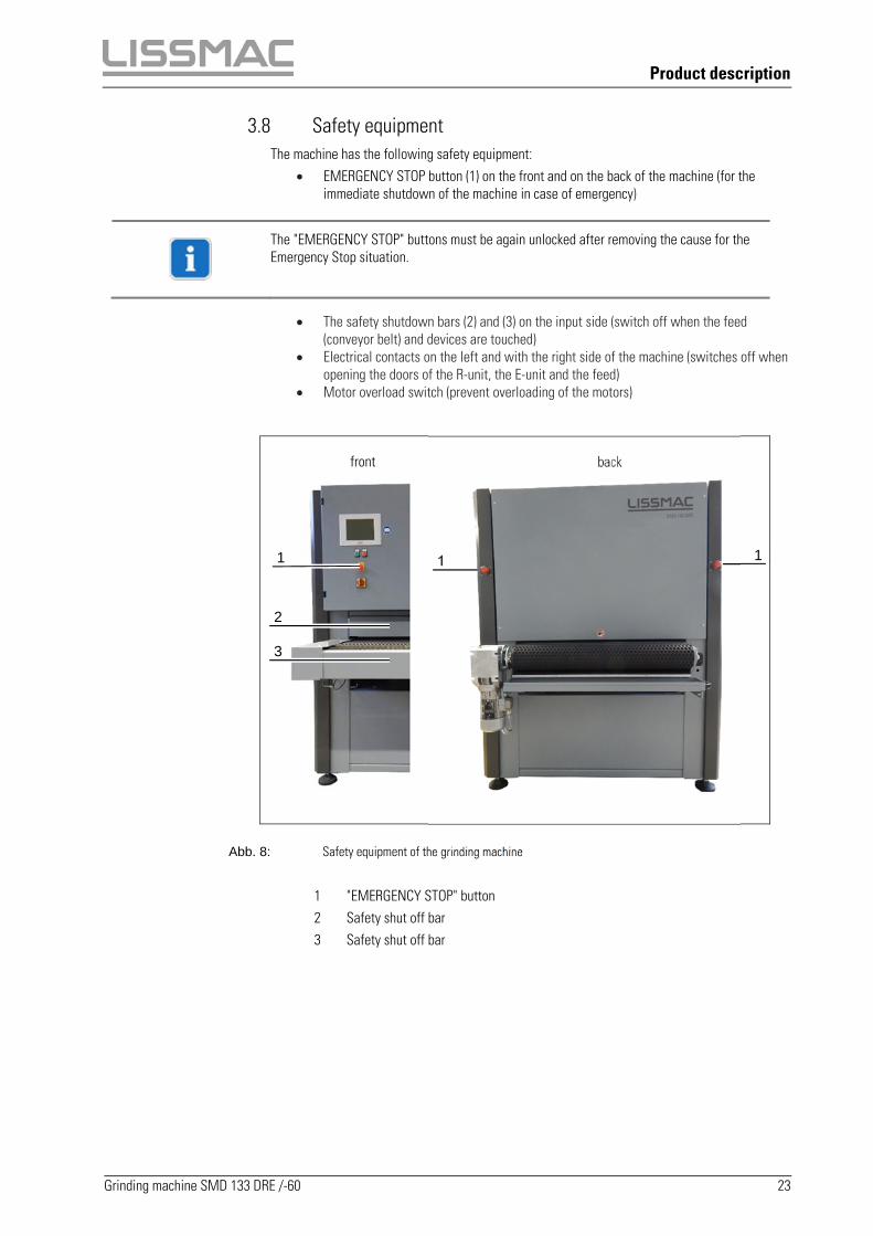
3.8 Safety equipment The machine has the following safety equipment:
EMERGENCY STOP button (1) on the front and on the back of the machine (for the immediate shutdown of the machine in case of emergency)
The "EMERGENCY STOP" buttons must be again unlocked after removing the cause for the Emergency Stop situation.
The safety shutdown bars (2) and (3) on the input side (switch off when the feed (conveyor belt) and devices are touched)
Electrical contacts on the left and with the right side of the machine (switches off when opening the doors of the R-unit, the E-unit and the feed)
Motor overload switch (prevent overloading of the motors)
Abb. 8: Safety equipment of the grinding machine
1 "EMERGENCY STOP" button 2 Safety shut off bar 3 Safety shut off bar
front back
1
2
1
3
1

Preparation for use
24 Grinding machine SMD 133 DRE /-60
4 Preparation for use
4.1 Transporting the machine For transport of the machine by crane, there are two steel carriers (1) fastened to the top of the machine with attachment points. Two braces (2) are mounted between the steel carriers (1) (for tightening torque refer to Section 6.3). There is a suspension point (3) located on each end of the steel carriers (1).
WARNING
Heavy loads
Injury from falling parts.
Do not stop under the lifted machine.
Only use lifting gear and loading equipment with sufficient lifting capacity and length.
To lift the machine, secure an appropriate lifting gear on the four attachment points.
Secure the machine by the four suspension points (3) with suitable lashing straps when transporting on a vehicle.
Abb. 9: Transport supports
1 Steel carriers with suspension points 2 Braces 3 Suspension point

Preparation for use
Grinding machine SMD 133 DRE /-60 25
4.2 Storing the machine Disconnect the electrical and pneumatic connections to the machine.
Thoroughly clean all grinding dust and material residue from the machine.
Clean the dust extraction shafts using an industrial vacuum cleaner.
Lubricate machine.
Pack the machine in plastic film for storage.
Do not store the machine outdoors.
Only store the machine in dry interior rooms.
4.3 Installation and unit 4.3.1 Installing machine
WARNING
Heavy loads
Injury from falling parts.
Do not stop under the lifted machine.
Only use lifting gear and loading equipment with sufficient lifting capacity and length.
Fasten suitable hoisting gear to the four attachment points and transport the machine with the loading equipment to the installation location.
Remove the packaging from the machine.
Set up the machine on a fortified, level floor with a surface load according to the layout.
Use the adjustable machine feet to level the machine in all directions.

Preparation for use
26 Grinding machine SMD 133 DRE /-60
4.3.2 Connecting the machine
DANGER
High voltage
Death or injury from electric shock.
Work on the machine's electrical systems may only be carried out by electricians accordingto the rules of electronics.
Place the main switch on the back of the machine into the "0" position.
Connect the machine to the power supply (see layout)
Connect compressed air supply on the pneumatic coupling box (1).
Unlock all three "EMERGENCY STOP" buttons.
The machine is delivered ready for connection to a right-hand power supply. When connection to the mains supply pay attention to the correct phase sequence.
Abb. 10: Connecting the machine
1 Pneumatic coupling
1

Preparation for use
Grinding machine SMD 133 DRE /-60 27
4.3.3 Connecting the extractor system
Observe the regulations for your extractor system and clarify these with the manufacturer as necessary. All national requirements for explosive steel dust must be met.
Extractor volume flow
Extractor pipes are installed in the grinding machine. These lead to a central point at the top of the machine. The flow speed in the pipe must be at least 20 m/s in order to achieve the best results. The specified volume flow must be complied with.
LISSMAC:
SMD 133 DRE min. 3000 m³/h
At the connection point, the piping should have the following diameter:
LISSMAC:
SMD 133 DRE Ø 180 mm
Connection of the grinding machine to the extractor system with seamless pipes with
integrated cleaning flaps.
To prevent the danger of dust deposits in the extractor pipes, only use seamless extractor pipes (not corrugated pipes). Provide inspection/cleaning flaps on all horizontal pipe sections upstream or downstream of pipe bends. Remove dust deposits via the inspection / cleaning flaps. Only use approved cleaning agents.
The extractor pipes must be grounded in order to prevent electrostatic charging. To avoid the danger of dust deposits in the extractor pipes the volume flow must be complied with.
On top of the machine, there is an interface (pipe connection), which is connected to the extractor system.
See the circuit diagram for the interface
Operation
28 Grinding machine SMD 133 DRE /-60
5 Operation
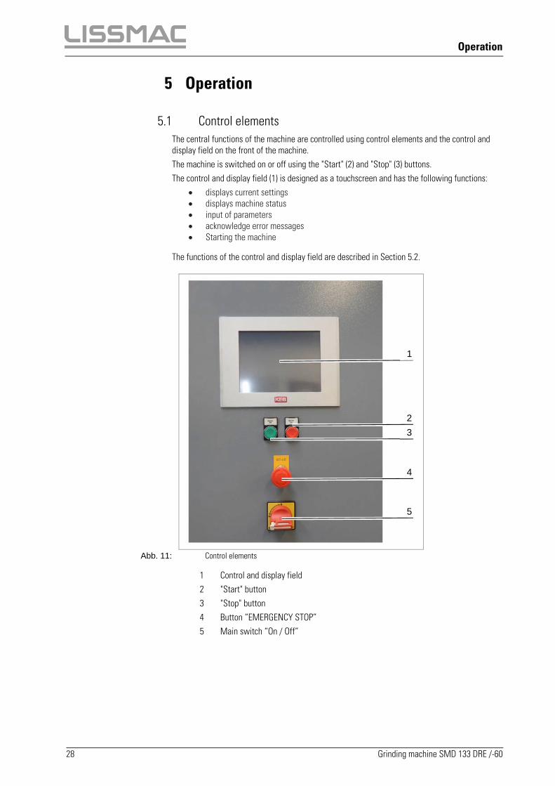
5.1 Control elements The central functions of the machine are controlled using control elements and the control and display field on the front of the machine. The machine is switched on or off using the "Start" (2) and "Stop" (3) buttons. The control and display field (1) is designed as a touchscreen and has the following functions:
displays current settings displays machine status input of parameters acknowledge error messages Starting the machine
The functions of the control and display field are described in Section 5.2.
Abb. 11: Control elements
1 Control and display field 2 "Start" button 3 "Stop" button 4 Button “EMERGENCY STOP” 5 Main switch “On / Off”
5
1
4
2
3

Operation
Grinding machine SMD 133 DRE /-60 29
5.2 Operating the control and display field 5.2.1 Screen set up
All functions and information of the machine are displayed on the touchscreen of the control and display field. Values or settings can be changed by touching buttons on the surface of the touchscreen.
Abb. 12: Screen set up
Item Function
1 Info area. The status of the machine with errors, the current selected screen and date and time are displayed in the info area.
2 Function buttons. The function buttons are screen-dependent and change depending on the screen display.
3 Constant buttons. The individual screens can be selected using the constant buttons. The constant buttons remain the same for each screen.
4 Main screen. Adjustment values and devices of the machine are shown on the main screen. A selected device is shown in white, a deselected device is shown in grey.
1
2
3
2
4

Operation
30 Grinding machine SMD 133 DRE /-60
5.2.2 Screen symbols
Abb. 13: Screen symbols
Item Function Item Function
1 "Fault" symbol 13 "Service" button. Pressing displays the screen with the service information.
2 "EMERGENCY STOP is activated" symbol 14 "Error messages" button. Pressing displays the screen with the error messages.
3 Symbol for selected screen (in the example: Start screen)
15 Acknowledge error
4 D-unit representation 16 Power input of R-Head
5 R-unit representation 17 Display of current feed speed
6 E-unit representation 18 Display cutting speed. Adjustment possibility by tapping the field.
7 "Home" button. Pressing displays the start screen. 19 Display aggregate active / not active. You can select or deselect by clicking the Aggregate icon.
8 "Sheet metal thickness" button. Pressing displays the screen of the sheet metal thickness.
20 Feed display
9 "D-unit" button. Pressing displays the screen of the D-unit.
21 Slider feed speed
10 "R-unit" button. Pressing displays the screen of the R-unit.
22 Sheet metal thickness display. Adjustment possibility by tapping the field.
11 "E-unit" button. Pressing displays the screen of the E-unit.
23
The symbols of the function buttons are different depending on the screen. Symbols are described in the corresponding section. Shown here: Running direction of the conveyor belt.
12 Password level button. For machine set-up man and service personnel of manufacturer.
3 2
14 13 12 11
5
9 10 8 7
1 4 6
15
20
17
21
22
16 23
19
18

Operation
Grinding machine SMD 133 DRE /-60 31
5.2.3 Setting the sheet thickness
Abb. 14: Sheet metal thickness screen
Actual value (1) and target value (2) of the sheet metal thickness are displayed on the main screen. Actual value = current position of the tool Target value = desired position of the tool
WARNING
Thrown out workpieces
Injuries due to thrown out workpieces.
During processing do not adjust the height.
NOTE
Workpieces remaining in the machine
Damage to the machine
Ensure that no workpieces remain in the machine.
Press the "sheet metal thickness" button (3). The sheet metal thickness screen appears.
Measure the sheet thickness of the work piece to be processed.
Press "Target value" (2) display field. The input field (4) appears.
Enter the measured sheet metal thickness using the keyboard and confirm.
The function buttons (5) and (6) can be used in jog mode for free movement.
For thicker sheet metal: Press function button (5). Height adjustment moves upward.
1
5
2
6
3
4

Operation
32 Grinding machine SMD 133 DRE /-60
For thinner sheet metal: Press function button (6). Height adjustment moves downwards.
5.2.4 Selecting/deselecting D-unit
Abb. 15: D-unit screen
Selecting deselected D-unit:
Press the "D-unit" button (1). The D-unit screen appears.
Press function button (2). The symbol for the D-unit (3) lights up white and a check mark is shown in the checkbox (4).
Deselecting selected D-unit:
Press the "D-unit" button (1). The D-unit screen appears.
Press function button (2). The symbol for the D-unit (3) lights up grey and an "x" is shown in the checkbox (4).
2
3
4
1

Operation
Grinding machine SMD 133 DRE /-60 33
5.2.5 Selecting/deselecting R-unit
Abb. 16: R-unit screen
Selecting deselected R-unit:
Press the "R-unit" button (1). The R-unit screen appears.
Press function button (2). The symbol for the R-unit (3) lights up white and a check mark is shown in the checkbox (4).
Deselecting selected R-unit:
Press the "R-unit" button (1). The R-unit screen appears.
Press function button (2). The symbol for the R-unit (3) lights up grey and an "x" is shown in the checkbox (4).
2
3
4
1

Operation
34 Grinding machine SMD 133 DRE /-60
5.2.6 Adjusting the cutting speed
Abb. 17: Adjusting the cutting speed
Press the "R-unit" button (1). The R-unit screen appears.
Press on the display field (2) of the cutting speed. Input field (3) appears.
Enter the desired cutting speed using the keyboard and confirm.
The feed speed can be set in a range from 4 to 6 m/s.
5.2.7 Power input R-Head
Abb. 18: Power input R-Head
When the R-Head is selected:
Press push- button "Power input R-Head" (1). Readout of power input of R-Head (2) appears.
If the readout of the power input is in the yellow / red range, the positioning of the R-Head has to be reduced.
2
3
1
2
1
Operation
Grinding machine SMD 133 DRE /-60 35
5.2.8 Selecting/deselecting E-unit
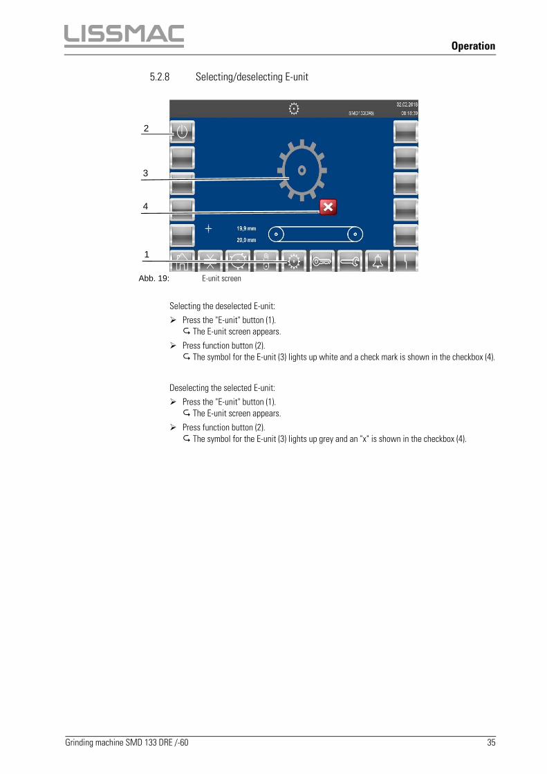
Abb. 19: E-unit screen
Selecting the deselected E-unit:
Press the "E-unit" button (1). The E-unit screen appears.
Press function button (2). The symbol for the E-unit (3) lights up white and a check mark is shown in the checkbox (4).
Deselecting the selected E-unit:
Press the "E-unit" button (1). The E-unit screen appears.
Press function button (2). The symbol for the E-unit (3) lights up grey and an "x" is shown in the checkbox (4).
2
3
4
1

Operation
36 Grinding machine SMD 133 DRE /-60
5.2.9 Calling up password level screen
Abb. 20: Password protected area screen
Press the "Password level" button (1). The input field (2) for entering user name and password appears.
The password level is reserved for the machine setters and the service technicians of the manufacturer.
3
1

Operation
Grinding machine SMD 133 DRE /-60 37
5.2.10 Calling up service pages
Abb. 21: Service screen, operating hours counter page
The service screen consists of three pages. The pages can be paged through using the arrow buttons (2) and (3).
Press the "Service" button (1). The first page of the service screen appears.
The following information is displayed on the first page of the service screen: Feed operating hours (4) D-unit operating hours (5) R-unit operating hours (6) E-unit operating hours (7)
Abb. 22: Service screen, frequency converter page
The input/output signals for the frequency converter for the feed is displayed on the second page of the service screen. If there is a signal applied to a frequency converter, the corresponding dot symbol is shown in green.
4
2
5
6
7
3
1

Operation
38 Grinding machine SMD 133 DRE /-60
Abb. 23: Service screen, calibration page
The current calibration is displayed on the third page of the service screen. The display is for information only. Adjustment values cannot be changed by the user.
5.2.11 Calling up error messages
Abb. 24: Error messages screen
Press the "Error message" button (1).
All current faults or error messages are shown in the Table (2) in bold font. The status of an active message is "ON".
Remedy fault/error.
Press button (3) to acknowledge the error message.
If a fault or error is remedied, the message text in the table (2) is shown in normal font. The status of an inactive message is "OFF".
2
3
1

Operation
Grinding machine SMD 133 DRE /-60 39
5.2.12 Setting the feed speed
Abb. 25: Setting the feed speed
The feed speed of the conveyor belt is set via the slider (1).
For the optimum grinding result the feed speed must be adjusted according to the work piece. The feed speed can be set from 0.5 to 8 m/s.
Push the slider upwards or downwards. The selected feed speed (2) is displayed on the main screen.
5.3 Turning on the machine Remove contamination such as material residue and dust deposits.
Make sure that the grinding belt and grinding mops are free of damage (visual inspection).
Make sure that all "EMERGENCY STOP" buttons are unlocked.
Place the main switch on the back of the machine into the "I" position. The machine is switched on.
Before you can start working on the workpieces, the following prerequisites must be met: • The sheet thickness of the workpieces is measured and set on the machine. • Feed speed is set. • Top and bottom machining units are correctly positioned.
5.4 Switch off the machine
Ensure that no workpiece is left in the machine.
Press the "Stop" button.
Set the main switch on the back of the machine to position "0". The machine is switched off.
2
1

Operation
40 Grinding machine SMD 133 DRE /-60
5.5 The machine into operation
WARNING
Explosion hazard
Dust particles can enter the respiratory tract through dust turbulence. The dust turbulences can ignite during grinding.
The machine may only be operated with a functional dust extraction device corresponding to the country-specific rules (e.g. EC directive) and approved for steel dust and stainless steel dust.
Use personal protective equipment (e.g. work gloves, safety glasses, ear protection) if necessary or if required by country-specific rules.
Turn on machine (see section 5.3).
Make sure that all malfunctions are corrected (see section 5.2.11).
Select the required devices for the machining (see Sections 5.2.4 and 5.2.7).
If the R-unit is used: Set cutting speed (see Section 5.2.6).
Set feed speed (see Section 5.2.12).
Press the "Start" button.
The symbol appears on the main screen in yellow and the devices move to the selected
position. When the machine is set the (1) symbol is shown in green.
If all devices are already in work position (e.g. after a pause) and the "Start" button is pressed
for the first time, then the symbol appears immediately in green. The machine can then
be started immediately by pressing on the (1) symbol.
Wait until the symbol is shown in green.
Press the (1) symbol. The machine runs.
1

Operation
Grinding machine SMD 133 DRE /-60 41
5.6 Processing material
NOTE
Minimum dimensions of the workpiece
Damage to the machine and/or the workpiece
The minimum dimensions of a workpiece are 150 x 100 x 3.0 mm.
It must be ensured with short workpieces that the passage length is at least 150 mm. Placeshort workpieces parallel to the conveyor belt if necessary.
CAUTION
Conveyor belt on the input side
Cutting of fingers when putting on the workpiece
Wear protective gloves.
Do not reach into the input opening for workpieces.
Lay workpieces on the front edge of the conveyor belt.
CAUTION
Flying sparks
Eye injuries due to flying sparks
Wear safety glasses.
Abb. 26: Processing material
Operation
42 Grinding machine SMD 133 DRE /-60
NOTE
Unsuitable workpieces
Damage to the machine, premature wear of the power-pin belts
Only remove slag of workpieces with the corresponding minimum length (150 mm) and minimum width (100 mm) and minimum thickness (3 mm) and with the same thickness throughout.
Adjust the material thickness value on the machine for workpieces of different thicknessesas required.
Distribute workpieces evenly over the width of the conveyor belt and lay the outer edge of the workpieces as diagonally as possible on the conveyor belt.
Allow hot workpieces to cool before removing slag.
Acceptance of the workpieces at the output side of the machine is ensured.
Place workpiece onto the conveyor belt.
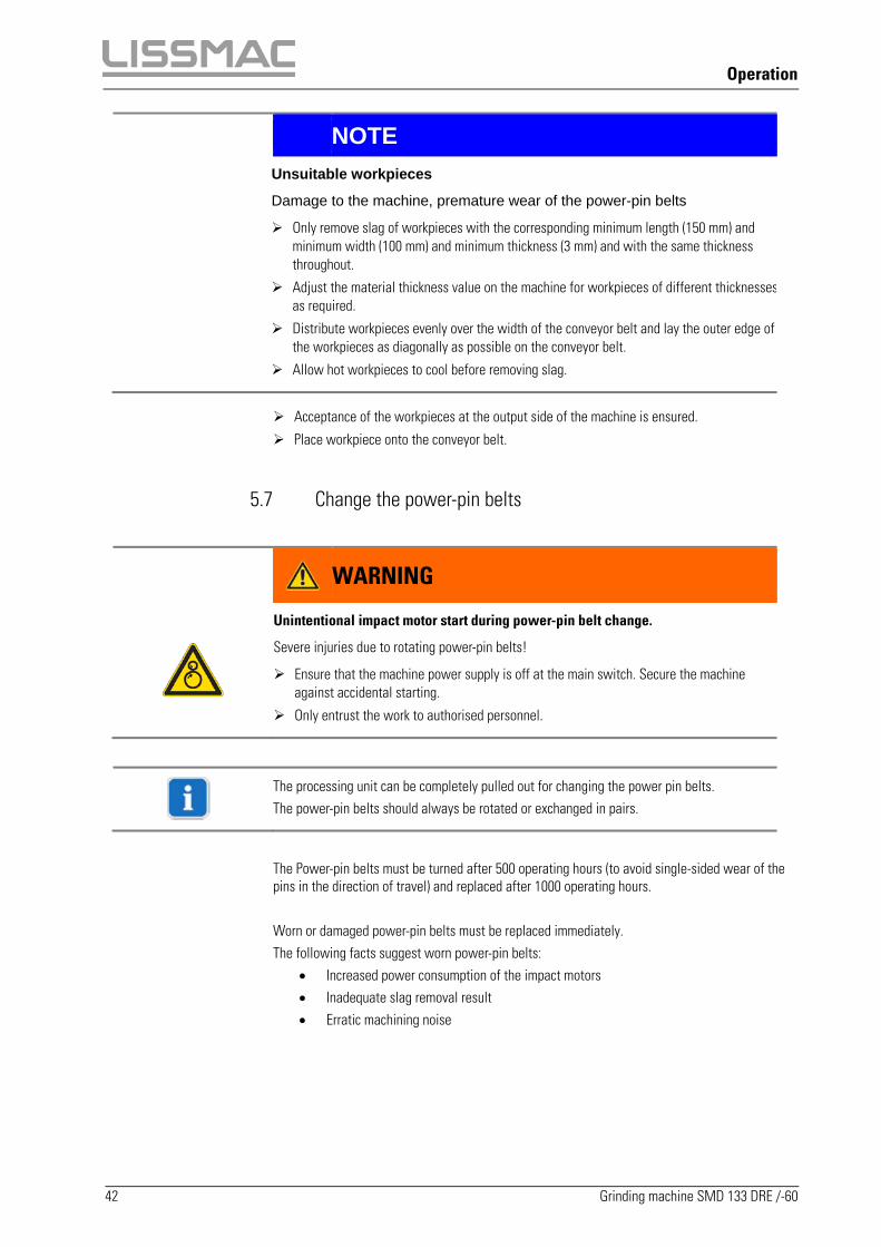
5.7 Change the power-pin belts
WARNING
Unintentional impact motor start during power-pin belt change.
Severe injuries due to rotating power-pin belts!
Ensure that the machine power supply is off at the main switch. Secure the machine against accidental starting.
Only entrust the work to authorised personnel.
The processing unit can be completely pulled out for changing the power pin belts. The power-pin belts should always be rotated or exchanged in pairs.
The Power-pin belts must be turned after 500 operating hours (to avoid single-sided wear of the pins in the direction of travel) and replaced after 1000 operating hours. Worn or damaged power-pin belts must be replaced immediately. The following facts suggest worn power-pin belts:
Increased power consumption of the impact motors Inadequate slag removal result Erratic machining noise

Operation
Grinding machine SMD 133 DRE /-60 43
Abb. 27: Change the power-pin belts
1 Protective cover power pin unit 2 4x Hexagonal bolt SW 10 3 2x Hexagonal bolt SW 24
Turn off the machine (see section 5.4 Switch off the machine).
Open the left machine door.
Remove the protective cover of the power pin belts via the 4 hexagon bolts (pos. 2).
Loosen the two hexagon bolts (pos. 3) and pull out the complete processing unit.
Abb. 28: Tensioning unit power pin belt
2 2
1
3 3
22

Operation
44 Grinding machine SMD 133 DRE /-60
Abb. 29: Change the power-pin belts
Loosen the counter nut (1) on the tensioning unit.
Loosen screw (2) until the power-pin belts are relaxed.
Remove the power-pin-belts.
Clean the drive and deflection rollers after the power-pin belts have been removed and check them for damage and wear.
Rotate the power-pin belts in the opposite direction to the running direction and either re-insert them or replace with new power-pin belts.
Tighten the power-pin belts using screws (2) until the pressure plate is placed (3) between the arrows.
Secure the setting using the lock nut (1). Check for functionality. Insert the processing unit Fix them into position via the two hexagon bolts. Attach the protective cover again via the four hexagon bolts (2). Close the doors again. Reset the standard settings for the machining units.
Insert the impact belts and tighten
them
2 1
3

Operation
Grinding machine SMD 133 DRE /-60 45
5.8 Set the height of power pin belts
Abb. 30: Deliver the power pin belts
After a change of the power pin belts or the wear of the power pins, the height must be readjusted.
Unscrew the protective cover of the power pin belt unit (see 5.6)
Move the material to be processed under the power pin belts with the push button feed (pos. 1).
Advance the power pin belts by turning the adjusting screw (pos. 2) until they touch the material.
Remove material with the push-button feed (pos.1).
Assemble the protective cover of the power pin belt unit again (see 5.6)
1
2

Operation
46 Grinding machine SMD 133 DRE /-60
5.9 Change grinding belt
WARNING
Accidental starting of the grinding motors during replacement of the grinding belt
Severe injuries due to rotating grinding belt
Turn off the main switch.
Only have the grinding belt replaced by authorised persons.
Abb. 31: Change grinding belt
1 Grinding belt 2 Tensioning drum switch 3 Belt running switch 4 Device support 5 Unit support
Switch off machine (see Section 5.4).
Open left machine door.
Swing the belt running switch (3) in the direction of the door until it stops
Release tension on grinding belt. To do this set the tensioning drum switch (2) to the "0" position.
Remove the device support (4).
1
2
3
4
5
Operation
Grinding machine SMD 133 DRE /-60 47
Pull off the grinding belt (1) from the R-unit.
Push a new grinding belt (1) on the R-unit, paying attention to the correct running direction.
Install the device support (4).
Tension the grinding belt. To do this set the tensioning drum switch (2) upward to the "1" position.
Swing the belt running switch (3) in the direction of the machine room until it stops
Set the grinding belt height (see Section �).
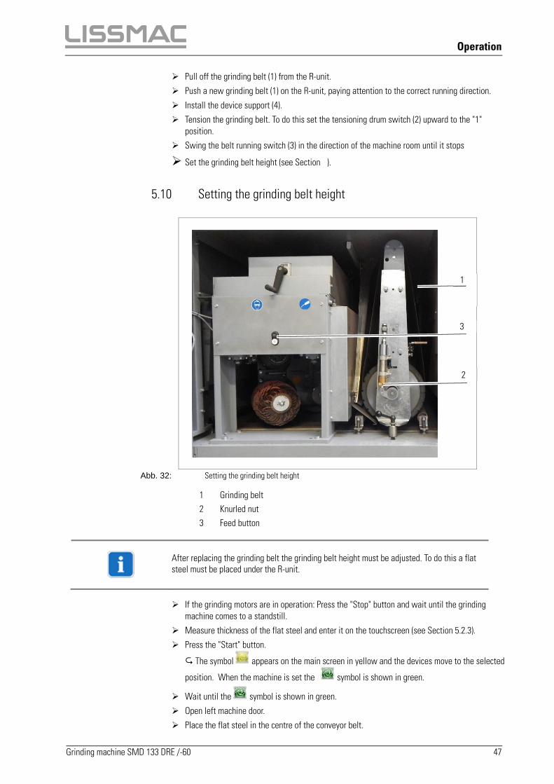
5.10 Setting the grinding belt height
Abb. 32: Setting the grinding belt height
1 Grinding belt 2 Knurled nut 3 Feed button
After replacing the grinding belt the grinding belt height must be adjusted. To do this a flat steel must be placed under the R-unit.
If the grinding motors are in operation: Press the "Stop" button and wait until the grinding machine comes to a standstill.
Measure thickness of the flat steel and enter it on the touchscreen (see Section 5.2.3).
Press the "Start" button.
The symbol appears on the main screen in yellow and the devices move to the selected
position. When the machine is set the symbol is shown in green.
Wait until the symbol is shown in green.
Open left machine door.
Place the flat steel in the centre of the conveyor belt.
1
3
2

Operation
48 Grinding machine SMD 133 DRE /-60
Transport the flat steel under the R-unit. To do this press the feed (3) button.
Check the setting of the grinding belt height. To do this, turn the grinding belt (1) manually.
The grinding belt height is correctly set if scratching of the grinding belt on the flat steel can be heard or seen.
If necessary, correct the grinding belt height. To do this, turn the knurled nut (2).
Abb. 33: Adjusting the conveying direction
1 Conveying into the machine 2 Conveying out of the machine
The conveying direction can be adjusted by pressing the function button (1 or 2). When the machine door is closed the conveying direction is automatically correctly set.
Transport the flat steel out of the machine. To do this press the feed button.
Close left machine door.
2 1

Operation
Grinding machine SMD 133 DRE /-60 49
5.11 Replacing the grinding mops
Abb. 34: Replacing the grinding mops
1 Grinding mop 2 Disk 3 nut 4 Direction of rotation sign
The grinding mops on the left and on the right side of the machine are replaced in the same manner. In the following the work steps for the left side are described.
Switch off machine (see Section 5.9).
Open left machine door.
NOTE
The nut has a left-hand or right-hand thread, depending on the direction of rotation of the grinding mop. Nuts with a left-hand thread are marked with an arrow.
Pay attention to the direction of rotation of the grinding mop.
Unscrew nut (3).
Remove the grinding mop (1) with washer (2) from the shaft.
Slide a new grinding mop (1) with washer (2) on the shaft while observing the direction of rotation according to the sign (4).
Screw the nut (3) on the shaft and tighten with the specified tightening torque (see Section 6.3).
Set the grinding mop height (see Section 5.12).

Operation
50 Grinding machine SMD 133 DRE /-60
5.12 Adjust the grinding mop height
Abb. 35: Adjust the grinding mop height.
1 Display of wear of the grinding mop 2 Height adjustment crank 3 Feed button 4 E-unit motor button 5 Grinding mop
The grinding mop height must be adjusted after a grinding mop change or with advanced wear. To do this a flat steel must be placed under the E-unit.
If the grinding motors are in operation: Press the "Stop" button and wait until the grinding machine comes to a standstill.
Measure thickness of the flat steel and enter it on the touchscreen (see Section 5.2.3).
Press the "Start" button.
The symbol appears on the main screen in yellow and the devices move to the selected
position. When the machine is set the symbol is shown in green.
Wait until the symbol is shown in green.
Open the left, and if necessary the right, machine door.
Place the flat steel in the centre of the conveyor belt.
Transport the flat steel under the E-unit. To do this press the feed (3) button.
Check the setting of the grinding mop height. To do this start the grinding mop (5) with E-unit motor button (4).
1
2
3
4
5

Operation
Grinding machine SMD 133 DRE /-60 51
The grinding mop height is correctly set if scratching of the grinding mop on the flat steel can be heard or seen.
If necessary, correct the grinding mop height. To do this, turn the height adjustment crank (1).
Abb. 36: Adjusting the conveying direction
1 Conveying into the machine 2 Conveying out of the machine
The conveying direction can be adjusted by pressing the function button (1 or 2). When the machine door is closed the conveying direction is automatically correctly set.
Transport the flat steel out of the machine. To do this press the feed button.
Close the left and, if open, the right machine door.
2 1

Service
52 Grinding machine SMD 133 DRE /-60
6 Service
6.1 Service intervals
Perform the following service work regularly in the specified intervals. The intervals are shortened corresponding to multiple-shift operation.
Service work Interval
Clean the interior of the machine (see Section 6.4) daily / once per shift every 8 hrs.
Lubricate the lubrication nipples of the guide blocks (see Section 6.7)
every 100 hrs.
Check drive belts and deflection rollers for wear daily / once per shift
Tension chains every 1500 hrs.
Check V-belt tension every 250 hrs.
Check the maintenance unit for compressed air (see section 6.7 Lubricating the guide blocks)
daily / once per shift every 8 hrs.
Clean the magnets daily/once per shift
Change power-pin-belt every 500 hrs.
Rotate power-pin-belt every 1000 hrs.
Tension and lubricate the chains Quarterly
6.2 Lubricant table
Lubricant / Cleaner Designation
Grease Multi-purpose grease(NLGI class EP 2)

Service
Grinding machine SMD 133 DRE /-60 53
6.3 Tightening torque for standard metric thread All maximum permissible tightening torques listed here apply to threaded connections with ISO 4014 – 4018 hexagon head screws and ISO 4762 hexagon socket head screws, as well as screws with analogous head strength for a friction coefficient of μtot = 0.12.
Maximum tightening torque Maximum Ma in Nm
Hexagon head screws / hexagon socket head screws / hex nuts
ISO 898/1 strength classes
8.8 10.9 12.9
M4 2.5 4 4.5
M5 5 7.5 9
M6 9 13 15
M7 14 20 25
M8 22 30 35
M10 45 65 75
M12 75 105 125
M14 115 170 200
M16 180 260 310
M18 260 370 430
M20 360 520 600
M22 490 700 820
M24 620 890 1040

Service
54 Grinding machine SMD 133 DRE /-60
6.4 Cleaning The machine must be cleaned after every shift (every 8 hrs.) and material residue must be removed.
WARNING
Unintentional starting of the grinding/impact motors during cleaning
Danger of serious injuries from rotating grinding means
Ensure that the power supply of the machine is switched off by the main switch.
Secure against restarting.
Only have the machine cleaned by authorised persons.
Turn off the main switch (5.4 Switch off the machine).
Open side doors.
WARNING
Explosion hazard
Steel dust can react explosively.
Make sure that grinding dust does not come in contact with ignition sources.
Extract grinding dust and material residues from the machine interior, the intake area, the exhaust duct, suction pipes, and the collection duct at the end of the conveyor with an industrial vacuum cleaner
Close the side doors.
Dispose of grinding dust and material residue.
Grinding dust and material residue must be disposed of in accordance with applicable country-specific law.

Service
Grinding machine SMD 133 DRE /-60 55
6.4.1 Cleaning of the magnets of the power-pin-belts
Abb. 37: Cleaning of the magnets
Switch the machine off (see 5.4 Switch off the machine). Move out the unit of the power pin belts (5.7 Change the power-pin belts) Pull off the safety cover of the magnets (pos. 1) towards the front. Fold up the magnetic holder (pos. 2) and secure it via the lever (pos. 35). Remove any slag adhering to the magnets (the magnet sleeve (pos. 36) can be removed by
pulling down).
Cleaning the interior and magnets
1
1
Service
56 Grinding machine SMD 133 DRE /-60
Extract slag at and around the magnets (pos. 34) with an industrial vacuum cleaner. Replace the magnet sleeves and the safety cover. Reposition the unit of the power pin belts ( 5.7 Change the power-pin belts) Close doors again.
Slag and material residues must be disposed of in accordance with the applicable regulations.
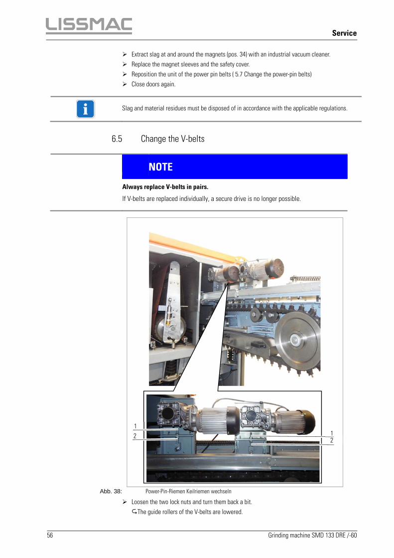
6.5 Change the V-belts
NOTE
Always replace V-belts in pairs.
If V-belts are replaced individually, a secure drive is no longer possible.
Abb. 38: Power-Pin-Riemen Keilriemen wechseln
Loosen the two lock nuts and turn them back a bit. The guide rollers of the V-belts are lowered.
1 2
2 1

Service
Grinding machine SMD 133 DRE /-60 57
Renew the V-belts. Re-tension the V-belts by tightening the lock nut (pos. 1). Pressure test.If the V-belt yields a fingerbreath, the correct belt tension has been reached.
Lock the two nuts (pos 1 and 2) with each other, in order to fix the setting of the respective V-belt.
Abb. 39: Change the V-belts
Service
58 Grinding machine SMD 133 DRE /-60
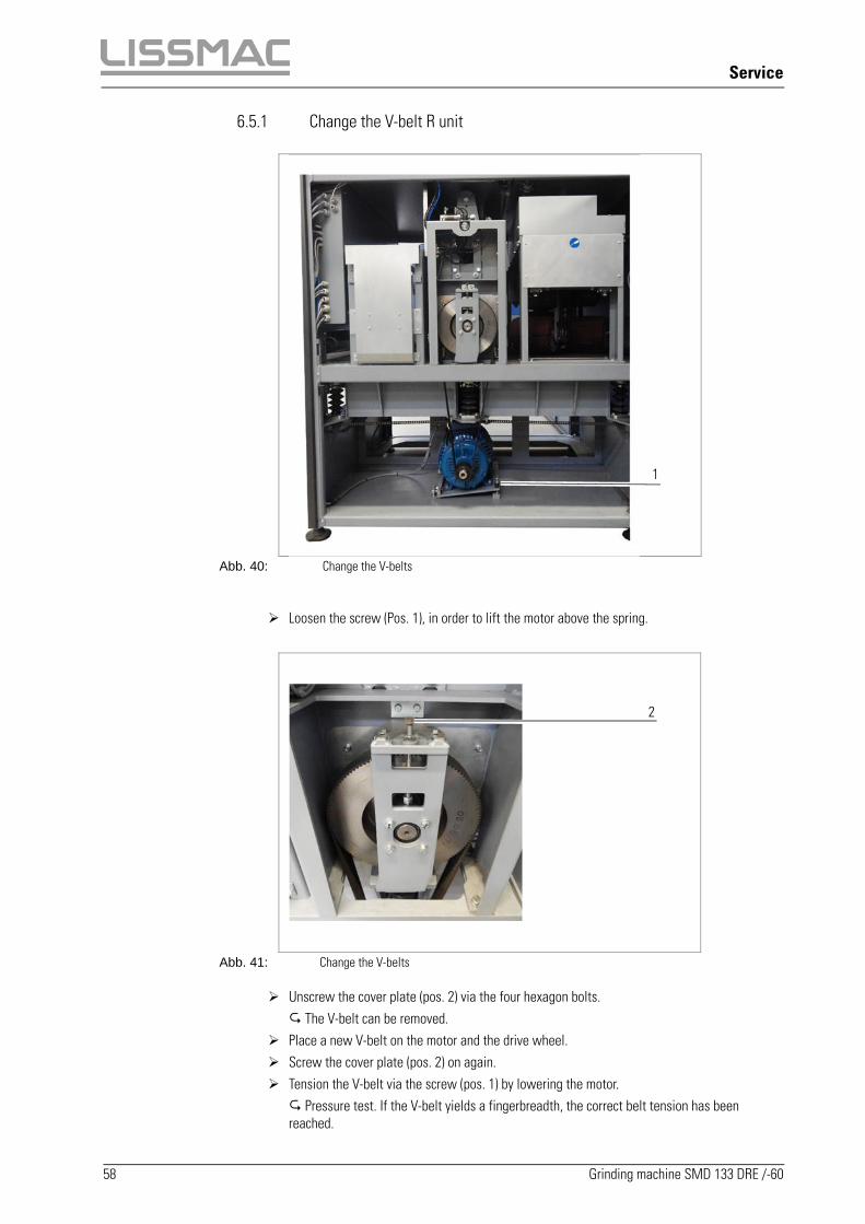
6.5.1 Change the V-belt R unit
Abb. 40: Change the V-belts
Loosen the screw (Pos. 1), in order to lift the motor above the spring.
Abb. 41: Change the V-belts Unscrew the cover plate (pos. 2) via the four hexagon bolts. The V-belt can be removed.
Place a new V-belt on the motor and the drive wheel. Screw the cover plate (pos. 2) on again. Tension the V-belt via the screw (pos. 1) by lowering the motor. Pressure test. If the V-belt yields a fingerbreadth, the correct belt tension has been reached.
1
2

Service
Grinding machine SMD 133 DRE /-60 59
6.6 Lubrication points 6.6.1 Lubricate the power pin belt unit
Abb. 42: Lubrication points power pin belt unit
Move out the unit of the power pin belts (see 5.7 Change the power-pin belts) Lubricate the lubrication points with a grease gun (see 6.2 Lubricant table) Position the unit of the power pin belts again (see 5.7 Change the power-pin belts) Close the machine door
Service
60 Grinding machine SMD 133 DRE /-60
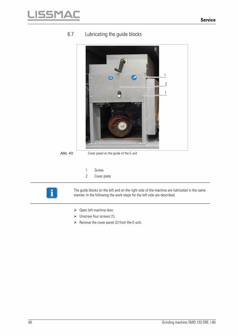
6.7 Lubricating the guide blocks
Abb. 43: Cover panel on the guide of the E-unit
1 Screw 2 Cover plate
The guide blocks on the left and on the right side of the machine are lubricated in the same manner. In the following the work steps for the left side are described.
Open left machine door.
Unscrew four screws (1).
Remove the cover panel (2) from the E-unit.
1
2
1

Service
Grinding machine SMD 133 DRE /-60 61
Abb. 44: Lubrication points on the guide block
1 Lubrication point, right 2 Left lubrication point
Lubricate lubrication points (1) and (2).
Fasten cover panel with four screws on the E-unit. Tighten screws with specified tightening torque (see Section 6.3).
Lubricate the lubrication points on the right side of the machine in the same manner.

Service
62 Grinding machine SMD 133 DRE /-60
6.8 Checking the service unit for compressed air
Abb. 45: Left side of the machine -> Service unit
Abb. 46: Service unit
1 Service unit 2 View window 3 Valve
Switch off the machine and secure it against restarting.
Open the left machine door
Check in the view window (2) whether condensation has accumulated in the service unit (1).
If necessary, open the valve (3) and drain condensate.
3
1
2

Troubleshooting
Grinding machine SMD 133 DRE /-60 63
7 Troubleshooting
If the machine is not working or is not working correctly, the following malfunctions may pertain:
Error Display/behaviour Cause Solution
1 Machine does not start
The "EMERGENCY STOP" button in front or rear is pressed
Unlock "EMERGENCY STOP" button
Main switch is in position "0" Set the main switch to the "1" position
Left and/or right machine door is open Close machine door(s)
Door contact switch is faulty Inform electrician
Upper safety shut off bar triggered Set correct sheet metal thickness (see Section 5.2.3)
Volume flow of the extraction system is not sufficient
Clean suction system and pipes.
Check piping for leaks.
2 No display on control and display field Main switch is in position "0" Set the main switch to the "1" position. If the fault is not remedied: Inform electrician
3 D-unit does not run D-unit is deselected Select D-unit (see Section 5.2.4)
R-unit does not run R-unit is deselected Select R-unit (see Section 5.2.45)
4 E-unit does not run E-unit is deselected Select E-unit (see Section 5.2.78)
5 Conveyor belt does not run Switch bar on conveyor belt is actuated Free switch bar
6 Grinding result insufficient Grinding belt is worn Replace grinding belt (see Section 5.9)
Distance of the grinding mop is too large (due to wear)
Correct the grinding mop height (see Section 5.12)
Cutting speed and/or feed is incorrectly set
Correct cutting speed and/or feed (see Section 5.2.6 and 5.2.122)
Customer service
64 Grinding machine SMD 133 DRE /-60
8 Customer service
If malfunctions occur which cannot be remedied by the customer themselves, contact the following customer service address:
LISSMAC Maschinenbau GmbH Lanzstraße 4 D-88410 Bad Wurzach Telephone: +49 (0) 7564 / 307 - 0 Fax: + 49 (0) 7564 / 307 - 500 E-mail: [email protected] Web: www.lissmac.com

Decommissioning and disposal
Grinding machine SMD 133 DRE /-60 65
9 Decommissioning and disposal
If the machine should be dismantled after the end of its service life, it must be properly disassembled. The individual parts must be taken to recycling and disposal.
The following parts of the machine contain environmentally hazardous substances: Electronic components of the controls Gears (lubricant)
Disconnect the machine from the power supply.
Disassemble the machine into individual parts and dispose of parts which contain environmentally hazardous substances according to the applicable national regulations.
Recycle the other machine parts according to their materials.

Warranty
66 Grinding machine SMD 133 DRE /-60
10 Warranty
The warranty for this machine is 12 months. For the following listed wear parts the warranty only applies if the wear is not caused by operation.
Feed and drive elements, such as toothed racks, gears, pinions, spindles, spindle nuts, spindle bearing, cables, chains, chain wheels, belts
Seals, cable, hoses, collars, connectors, couplings and switches for pneumatics, hydraulics, water, electrical, fuel
Guide elements, such as guide strips, guide bushings, guide rails, rollers, bearings, anti-slide plating
Tension elements from quick-coupling systems Plain and roller bearings, which do not run in oil bath Shaft sealing rings and sealing elements Friction and overload couplings, braking equipment Carbon brushes, collectors Easily dissolvable rings External potentiometer and manual switching elements Fuses and lamps Auxiliary and operating materials Fastening elements, such as pegs, anchors and screws Lamella Diaphragms Sealing brushes, sealing rubber, splash guard cloths All types of filters Drive and deflector rollers and bracings Running and drive wheels Transport belt Rubber scrapers Needle felt protection Energy storage Abrasive belts/grinding belts
Wear parts are parts that with intended use of the machine have limited operational wear. The wear time is not uniformly specified, it differs according to intensity of use. Wear parts must be serviced, adjusted, and replaced as needed corresponding to the specific device's operating manual provided by the manufacturer. Wear caused by operation does not qualify for warranty claims.

FOREWORD INSTALLATION DECLARATION
WARNING!
Carcinogenic substances which can cause damage to health may be released during grinding. It must be ensured that in case of failure or a reduction in the power of the extractor system,
further work with the grinding machine is not possible.
Operation without the extractor system is not use according to the intended purpose. Liability of the manufacturer for damage due to operation without the extractor system is excluded. All national requirements for the extractor system and the material which is to be extracted must be complied with. A dry dust extractor (e.g. DDE 3200) may be used as an extractor for machining steel and stainless steel. For machining of non-ferrous metals other than steel or stainless steel or for mixed operation with such materials, the extractor solution must always be agreed with LISSMAC.

This declaration is based on the Machinery Directive 2006/42/EC Annex VII Part B:
Declaration with respect to the incomplete machine
This declaration only relates to the machine in the state, in which it was brought into circulation; parts which are subsequently attached by the end user and / or subsequent modifications are not considered. The machine may only be put into operation if the system complies with the relevant regulations of Directive 2006/42/EC. In addition, Directive 2014/30/EU was applied.
Manufacturer: LISSMAC Maschinenbau GmbH Lanzstraße 4 D-88410 Bad Wurzach The technical documentation is archived by LISSMAC Maschinenbau GmbH, Lanzstraße 4, D-88410 Bad Wurzach.
Description
of the machine:
The LISSMAC SMD 133 DRE series grinding machine is used to round the edges of stamped, laser and fine plasma-cut workpieces and may only be operated in combination with an extractor which is approved according to the relevant EC Directive
SMD 133 DRE/-60
Voltage: 400V/50Hz / 480V/60Hz
Rated current: 63 A / 61 A
Rated power: 32,5 kW / 34 kW
Connection power: 40 kVA / 42 kVA
Protection class: IP 42
Weight: 2860 kg
Year of manufacture: 2019
Harmonized standards: EN ISO 12100:2011-03 EN 60204-1; VDE 0113-1:2007-06 EN 60204-1/A1; VDE 0113-1/A1:2009-10
Legally binding
authorized
representative:
LISSMAC Maschinenbau GmbH Lanzstraße 4 88410 Bad Wurzach Tel.: +49 (0) 7564 / 307 - 0 Mail: [email protected] / www.lissmac.com
Bad Wurzach 3/22/2018
……………………………. …………………………….
Klaus Kiefer (Manager)
on behalf Stefan Krummenauer (Product Manager)