Gyroboard Single Wheel Motorised Skateboard
20
www.iaset.us [email protected] GYROBOARD SINGLE WHEEL MOTORISED SKATEBOARD Omkar Rajesh Kachare Research Scholar, Department of Electronics and Telecommunication, Vishwakarma Institute of Information Technology, Pune, Maharashtra, India ABSTRACT Gyroboard is a single wheeled self-balancing skateboard. It will be used as a mode of commutation with action- filled experience. It is similar to a snowboard, surfboard, skateboard, and Marty McFly’s hoverboard all rolled into one KEYWORDS: Gyroboard, Gyroscope, Accelerometer, Go-kart Article History Received: 09 Aug 2018 | Revised: 28 Aug 2018 | Accepted: 08 Sep 2018 INTRODUCTION The Gyroboard is a single wheeled motorized skateboard. An onboard sensor reads that the foot is settled on the split platform, which allows the brushless motor inside the go-kart wheel to know it’s good to go. Lean forward and the board’s gyroscope balances and accelerates, sending you up of 5km/hr. The huge wheel smacked in the middle of the board makes any terrain feel smooth. Solid-state inertial sensors and algorithms balance the board around the wheel. Gyroboard will be Hands-free. One just has to lean forward to drive forward, back to stop and press your heels or toes to turn. With only one moving part, a revolutionary new type of brushless hub motor provides power and reliability. State-of-the-art lithium polymer (LiPO) batteries provide extended ride time. The charger charges in well under 2 hours. THEORY What is Self-Balancing? Self-balancing technology is not new, but it has made its way to all parts of the industry in the last couple of years. From smartphones and game console controllers to self-balancing pool tables and one-wheel scooters, this technology is changing and improving almost every aspect of our lives. But what is really self-balancing technology doing? How does it really work? The Backbone of Self Balancing Technology- Gyroscope. The secret behind the gyroscope always being in balance is in its free axis rotation. Basically, the gyroscope is a spinning wheel, or a disk, which has the completely free axis of rotation and it is able to assume any random orientation. Because the axis is free, no amount of tilting or moving can affect its balance. Unfortunately, gyroscopes, by themselves, are not enough to keep a device like a self-balancing board in balance . Even though these boards don’t require a big workout from your body, in order to stay aligned and balanced you will need to use your core muscles. Unlike cycling where you stay balanced by moving forward, on self- International Journal of Electrical and Electronics Engineering (IJEEE) ISSN(P): 2278-9944; ISSN(E): 2278-9952 Vol. 7, Issue 5, Aug- Sep 2018, 1-20 © IASET
-
Upload
khangminh22 -
Category
Documents
-
view
5 -
download
0
Transcript of Gyroboard Single Wheel Motorised Skateboard

www.iaset.us [email protected]
GYROBOARD SINGLE WHEEL MOTORISED SKATEBOARD
Omkar Rajesh Kachare
Research Scholar, Department of Electronics and Telecommunication,
Vishwakarma Institute of Information Technology, Pune, Maharashtra, India
ABSTRACT
Gyroboard is a single wheeled self-balancing skateboard. It will be used as a mode of commutation with action-
filled experience. It is similar to a snowboard, surfboard, skateboard, and Marty McFly’s hoverboard all rolled into one
KEYWORDS: Gyroboard, Gyroscope, Accelerometer, Go-kart
Article History
Received: 09 Aug 2018 | Revised: 28 Aug 2018 | Accepted: 08 Sep 2018
INTRODUCTION
The Gyroboard is a single wheeled motorized skateboard. An onboard sensor reads that the foot is settled on
the split platform, which allows the brushless motor inside the go-kart wheel to know it’s good to go. Lean forward and the
board’s gyroscope balances and accelerates, sending you up of 5km/hr. The huge wheel smacked in the middle of the board
makes any terrain feel smooth.
Solid-state inertial sensors and algorithms balance the board around the wheel. Gyroboard will be Hands-free.
One just has to lean forward to drive forward, back to stop and press your heels or toes to turn. With only one moving part,
a revolutionary new type of brushless hub motor provides power and reliability. State-of-the-art lithium polymer (LiPO)
batteries provide extended ride time. The charger charges in well under 2 hours.
THEORY
What is Self-Balancing?
Self-balancing technology is not new, but it has made its way to all parts of the industry in the last couple of
years. From smartphones and game console controllers to self-balancing pool tables and one-wheel scooters,
this technology is changing and improving almost every aspect of our lives. But what is really self-balancing technology
doing? How does it really work?
The Backbone of Self Balancing Technology- Gyroscope. The secret behind the gyroscope always being in
balance is in its free axis rotation. Basically, the gyroscope is a spinning wheel, or a disk, which has the completely free
axis of rotation and it is able to assume any random orientation. Because the axis is free, no amount of tilting or moving
can affect its balance. Unfortunately, gyroscopes, by themselves, are not enough to keep a device like a self-balancing
board in balance. Even though these boards don’t require a big workout from your body, in order to stay aligned and
balanced you will need to use your core muscles. Unlike cycling where you stay balanced by moving forward, on self-
International Journal of Electrical and
Electronics Engineering (IJEEE)
ISSN(P): 2278-9944; ISSN(E): 2278-9952
Vol. 7, Issue 5, Aug- Sep 2018, 1-20
© IASET

2
Impact Factor (JCC): 4.5095
balancing boards you use your core muscles to keep your alignment straight.
We have already seen, in the last few years, the rise
years ago no one would have ever thought that
the latest models that even that are within our reach.
SENSOR BASICS
What is a Gyroscope?
A gyroscope is a spinning wheel or disc in which the axis of rotation is free to assume any orientation by it. When
rotating, the orientation of this axis is unaffected by tilting or rotation of the mounting, according to
angular momentum. Because of this, gyroscopes are useful for measuring or maintaining orientation
Principle of Gyroscope
It works on the principle of conser
axis that is free to move on its own. The spinning wheel, or rotor, is mounted on a pivoting support that allows the rotation
around a single axis, called a gimbal. By using two g
the rotor three degrees of rotational freedom.
pointing in the same direction. Gyroscopes are mostly used as a
help of three very sensitive accelerometers one can detect the motion of the vehicle on which the gyroscope is mounted, on
all three axes.
Applications of gyroscopes include
the Hubble telescope, or inside the steel hull of a submerged submarine, or where a magnetic compass would not be precise
enough. Due to their precision, gyroscopes are also used in
mining.[3]
Gyroscopes can be used to construct
ships, aircraft, and spacecraft, vehicles in general), to assist in stability (
and Gyroboards) or be used as part of an inertial guidance system.
What is the Accelerometer?
An accelerometer is a device that measures
body in its own instantaneous rest frame
fixed coordinate system. For example, an accelerometer at rest on the surface of the Earth will measure an acceleration due
to Earth's gravity, straight upwards (by definition) of g
the center of the Earth at a rate of about 9.81
balancing boards you use your core muscles to keep your alignment straight.
We have already seen, in the last few years, the rise in popularity of hover boards
years ago no one would have ever thought that hover boards could be balanced without handles and we can see now with
the latest models that even that are within our reach.
is a spinning wheel or disc in which the axis of rotation is free to assume any orientation by it. When
rotating, the orientation of this axis is unaffected by tilting or rotation of the mounting, according to
. Because of this, gyroscopes are useful for measuring or maintaining orientation
It works on the principle of conservation of angular momentum, and consists of a spinning wheel supported on an
axis that is free to move on its own. The spinning wheel, or rotor, is mounted on a pivoting support that allows the rotation
around a single axis, called a gimbal. By using two gimbals at a time, one mounted inside the other, the gyroscope gives
the rotor three degrees of rotational freedom. As long as the rotor of the gyroscope is being spun, the gyroscope will keep
pointing in the same direction. Gyroscopes are mostly used as a basis for inertial navigation systems, meaning that with the
help of three very sensitive accelerometers one can detect the motion of the vehicle on which the gyroscope is mounted, on
Figure 1
Applications of gyroscopes include inertial navigation systems where magnetic compasses
, or inside the steel hull of a submerged submarine, or where a magnetic compass would not be precise
enough. Due to their precision, gyroscopes are also used in gyrotheodolites to maintain direction in tunnel
Gyroscopes can be used to construct gyrocompasses, which complement or replace magnetic compasses (in
and spacecraft, vehicles in general), to assist in stability (Hubble Space Telescope
or be used as part of an inertial guidance system.
is a device that measures proper acceleration.[1]
Proper acceleration, being the
rest frame,[2]
is not the same as coordinate acceleration, being the acceleration in a
. For example, an accelerometer at rest on the surface of the Earth will measure an acceleration due
to Earth's gravity, straight upwards (by definition) of g ≈ 9.81 m/s2. By contrast, accelerometers in
the center of the Earth at a rate of about 9.81 m/s2) will measure zero.
Omkar Rajesh Kachare
NAAS Rating 2.96
hover boards and similar devices. A few
could be balanced without handles and we can see now with
is a spinning wheel or disc in which the axis of rotation is free to assume any orientation by it. When
rotating, the orientation of this axis is unaffected by tilting or rotation of the mounting, according to the conservation of
. Because of this, gyroscopes are useful for measuring or maintaining orientation
vation of angular momentum, and consists of a spinning wheel supported on an
axis that is free to move on its own. The spinning wheel, or rotor, is mounted on a pivoting support that allows the rotation
imbals at a time, one mounted inside the other, the gyroscope gives
As long as the rotor of the gyroscope is being spun, the gyroscope will keep
basis for inertial navigation systems, meaning that with the
help of three very sensitive accelerometers one can detect the motion of the vehicle on which the gyroscope is mounted, on
magnetic compasses would not work, as in
, or inside the steel hull of a submerged submarine, or where a magnetic compass would not be precise
to maintain direction in tunnel
complement or replace magnetic compasses (in
Hubble Space Telescope, bicycles, motorcycles,
Proper acceleration, being the acceleration of a
is not the same as coordinate acceleration, being the acceleration in a
. For example, an accelerometer at rest on the surface of the Earth will measure an acceleration due
. By contrast, accelerometers in free fall (falling toward

Gyroboard Single Wheel Motorised Skateboard 3
www.iaset.us [email protected]
Figure 2
Accelerometers have multiple applications in industry and science. Highly sensitive accelerometers are
components of inertial navigation systems for aircraft and missiles. Accelerometers are used to detect and monitor
vibration in rotating machinery. Accelerometers are used in tablet computers and digital cameras so that images on screens
are always displayed upright. Accelerometers are used in drones for flight stabilization. Coordinated accelerometers can be
used to measure differences in proper acceleration, particularly gravity, over their separation in space; i.e., a gradient of
the gravitational field. This gravity gradiometry is useful because absolute gravity is a weak effect and depends on the local
density of the Earth which is quite variable.
History of Skateboarding
Skateboard History started sometime in the 1950’s. There were several booms and busts since then. Each boom
was lead by an increase in the quality of the skateboards. Then in the 90's powered by the innovative ways people started
using skateboards, they stuck around. Finally, the technology and the skills in skateboarding came together to create a
growing and very interesting sport called Skateboarding.
In 1950 there were roller-skates. The surfers were looking for stuff to do when the waves were dead. So they put
wheels on their boards. That is how the first skateboard was made. In 1972 the polyurethane wheel was invented. These
grippy and durable wheels allowed for a lot of control and higher speeds than in early skateboard history. The board got
wider so you could go faster and have more control. In 1975 electric skateboard came into existence. An electric
skateboard is typically a modified skateboard propelled by an electric motor, the power of which is usually controlled with
an RF remote. As with a regular skateboard, it is steered by the rider shifting his or her weight. In 2013, In the US, the
hover board aka self-balancing scooter was created and patented by Inventers.
In 2014, A new skateboard-like vehicle was introduced, this one simply called “Hoverboard”. It does, however,
move a bit like we imagine a hover board would move, something facilitated via a single wheel placed centrally under the
board.
This invention was basically our motivation. We wanted to build a skateboard with a single wheel for fun
locomotion. Gyroboard uses gyroscopic effect to balance the user on board, hence the name. It is basically the integration
of skateboard and gyroscope to give a boom to the evolution of the skateboards.
METHODOLOGY
Parts and Resource guide
This is a guide to the main parts that are required to construct the Gyroboard.
Control System
For the control system of the Gyroboard, we opted for an Arduino Development board. Arduino was the first

4
Impact Factor (JCC): 4.5095
preference due to its low pricing, the open community, user
to machine level operations.
Arduino is a DIY Development board with many variants. We choose Arduino UNO R3 for the gyroboard.
Arduino UNO is a microcontroller based board on the
used as PWM pins) a 16 MHz quartz crystal, a USB connection, a power jack, an ICSP header
contains everything needed to support the microcontroller; simply connect it
with an AC-to-DC adapter or battery to get started.
MEMS Accelerometer and Gyroscope:
Micro-Electro-Mechanical Systems, or MEMS, is a technology that in its most general form can be defined as
miniaturized mechanical and electro-mechanical elements (i.e., devices and structures) that are made using the techniques
of micro-fabrication.
We will be using an MPU-6050 Six
not only cheap but also easy to use and readily available.
The MPU-6050 parts are the world’s first
high-performance requirements of smart phones
The MPU-6050 devices combine a 3
with an onboard Digital Motion Processor
can access external magnetometers or other sensors through an auxiliary master I²C bus, allowing the devices to gather a
full set of sensor data without intervention from the system processor. The devices are offered in a 4 mm x 4 mm x 0.9 mm
QFN package.
For precision tracking of both fast and slow motions, the parts feature a user
of ±250, ±500, ±1000, and ±2000 °/sec (dps), and a user
preference due to its low pricing, the open community, user-friendly interface, moderately difficult coding and Easy access
Figure 3
Arduino is a DIY Development board with many variants. We choose Arduino UNO R3 for the gyroboard.
Arduino UNO is a microcontroller based board on the ATmega328P.It has 14 digital input/output pins (6 of which can be
used as PWM pins) a 16 MHz quartz crystal, a USB connection, a power jack, an ICSP header
contains everything needed to support the microcontroller; simply connect it to a computer with a USB cable or power it
DC adapter or battery to get started.
MEMS Accelerometer and Gyroscope:
Mechanical Systems, or MEMS, is a technology that in its most general form can be defined as
mechanical elements (i.e., devices and structures) that are made using the techniques
6050 Six-axis (Gyro + Accelerometer) MEMS MotionTracking Device. MPU6050 is
easy to use and readily available.
Figure 4
6050 parts are the world’s first Motion Tracking devices designed for the low power, low cost, and
smart phones, tablets, and wearable sensors.
050 devices combine a 3-axis gyroscope and a 3-axis accelerometer on the same silicon die, together
with an onboard Digital Motion Processor (DM), which processes complex 6-axis Motion Fusion algorithms. The device
other sensors through an auxiliary master I²C bus, allowing the devices to gather a
full set of sensor data without intervention from the system processor. The devices are offered in a 4 mm x 4 mm x 0.9 mm
Figure 5
both fast and slow motions, the parts feature a user-programmable gyro full
of ±250, ±500, ±1000, and ±2000 °/sec (dps), and a user-programmable accelerometer full-
Omkar Rajesh Kachare
NAAS Rating 2.96
friendly interface, moderately difficult coding and Easy access
Arduino is a DIY Development board with many variants. We choose Arduino UNO R3 for the gyroboard.
ATmega328P.It has 14 digital input/output pins (6 of which can be
used as PWM pins) a 16 MHz quartz crystal, a USB connection, a power jack, an ICSP header, and a reset button. It
to a computer with a USB cable or power it
Mechanical Systems, or MEMS, is a technology that in its most general form can be defined as
mechanical elements (i.e., devices and structures) that are made using the techniques
axis (Gyro + Accelerometer) MEMS MotionTracking Device. MPU6050 is
devices designed for the low power, low cost, and
axis accelerometer on the same silicon die, together
Fusion algorithms. The device
other sensors through an auxiliary master I²C bus, allowing the devices to gather a
full set of sensor data without intervention from the system processor. The devices are offered in a 4 mm x 4 mm x 0.9 mm
programmable gyro full-scale range
-scale range of ±2g, ±4g, ±8g,

Gyroboard Single Wheel Motorised Skateboard
www.iaset.us
and ±16g. Additional features include an embedded
the operating temperature range.
Motor
The Gyroboard initially was to be built with a HUB motor
hub drive, hub motor or in-wheel moto
directly. Hub motor electromagnetic fields are supplied to the stationary windings of the motor. The outer part
follows, or tries to follow, those fields, turning the attached wheel. In a brushed motor, energy is transferred by brushes
contacting the rotating shaft of the motor. Energy is transferred in a brushless motor electronically, eliminating phy
contact between stationary and moving parts.
But due to Budget and market limitations
motor. The DC motor that we have interfaced with the gyro
capable enough to rotate the go-kart wheel with PWM variations.
Motor Controller
As the current and voltage ratings of the DC motor are quite high, It cannot be directly interfaced with the
Arduino controller. To interface the DC motor a motor control drive is used.
Very few motor controllers were able to suffice the current and the voltage requirement of the motor. After an
extensive market research L289N, Dual H bridge motor controller was select
controlling motors speed and direction. An H
by Pulse Width Modulation (PWM).
and ±16g. Additional features include an embedded temperature sensor and an on-chip oscillator with ±1% variation over
The Gyroboard initially was to be built with a HUB motor. The wheel hub motor (also called
wheel motor) is an electric motor that is incorporated into the hub of a wheel and drives it
directly. Hub motor electromagnetic fields are supplied to the stationary windings of the motor. The outer part
follows, or tries to follow, those fields, turning the attached wheel. In a brushed motor, energy is transferred by brushes
contacting the rotating shaft of the motor. Energy is transferred in a brushless motor electronically, eliminating phy
contact between stationary and moving parts.
Figure 6
But due to Budget and market limitations, the build of the gyro-board had to be sufficed with a simple geared DC
motor. The DC motor that we have interfaced with the gyro-board is a 24V DC motor. It is a high torque, low RPM motor,
kart wheel with PWM variations.
As the current and voltage ratings of the DC motor are quite high, It cannot be directly interfaced with the
o interface the DC motor a motor control drive is used.
Figure 7
Very few motor controllers were able to suffice the current and the voltage requirement of the motor. After an
Dual H bridge motor controller was selected. H-Bridge's are typically used in
controlling motors speed and direction. An H-Bridge is a circuit that can drive a current in either polarity and be controlled
5
chip oscillator with ±1% variation over
(also called wheel motor, wheel
that is incorporated into the hub of a wheel and drives it
directly. Hub motor electromagnetic fields are supplied to the stationary windings of the motor. The outer part of the motor
follows, or tries to follow, those fields, turning the attached wheel. In a brushed motor, energy is transferred by brushes
contacting the rotating shaft of the motor. Energy is transferred in a brushless motor electronically, eliminating physical
board had to be sufficed with a simple geared DC
motor. It is a high torque, low RPM motor,
As the current and voltage ratings of the DC motor are quite high, It cannot be directly interfaced with the
Very few motor controllers were able to suffice the current and the voltage requirement of the motor. After an
Bridge's are typically used in
Bridge is a circuit that can drive a current in either polarity and be controlled

6 Omkar Rajesh Kachare
Impact Factor (JCC): 4.5095 NAAS Rating 2.96
Chain
The chain transfers the rotational power of the motor to the drive shaft of the wheel. We are using a timing chain
and timing sprockets to form a drive train. The timing sprocket and timing chain were salvaged from a Hero Splendor
Motorcycle. The drive sprocket is welded to the shaft of the motor, whereas the driven sprocket, after machining was
welded to the drive shaft of the go-kart wheel.
Wheel
The Go-Kart wheel is probably the most iconic thing* that makes the gyro board stand out from all other
skateboards available in the market. Gaining the perfect Go-kart wheel assembly was a difficult task. Market survey for the
wheel lasted for almost an entire week. The hard work paid off when we finally got the Go-Kart tyre with its assembly.
The assembly consists of a Go-Kart tyre of dimensions 7*11-5, the tyre rim and the coupler.
Wooden Frame
Designing a structure which could be used as a one wheel skateboard was a tedious task. We had many options to
choose from, The primary being Mild Steel, Aluminum, Fiberglass, and wood. To reduce the fabrication cost, wood was
selected. The fabrication and designing were customs made to match the dimensions of the Go-Kart wheel.
Figure 8
Steps Involved
Design and Construction
The Gyroboard design is inspired by one wheel, a ongoing skateboard product. We tried to recreate the same.
Using the knowledge and skills that we’ve gained in these 4 years
The following crucial steps were taken in designing the Gyroboard.
Raw Sketch
This image shows the raw sketch of the Gyroboard, it also gives the basic dimensions of the frame, Like Height,
Width, and Breadth of the frame.
Figure 9

Gyroboard Single Wheel Motorised Skateboard 7
www.iaset.us [email protected]
Go-Kart Tyre Sketch
The following image shows the dimensions of the tyre used.
The dimensions are 11*7.10-5The entire frame is designed around the dimensions of the tyre. Gyroboard being a
single wheel skateboard selecting the perfect tyre was a crucial step. The huge wheel in the board smoothes out any
potholes and any terrain makes smooth.
Figure 10
The Lean Angle
The lean angle decides the rotational speed of the motor that is the acceleration and descends depends on the lean
angle of the board.
Control System Designing.
The control system gathers the data from the Gyro + Accelerometer sensor, processes it and controls the PWM
which in turn controls the speed of the motor.
The control system designing is divided into the following phases.
Interfacing MPU6050 with Arduino:
The MPU6050 is connected to the Arduino Board for further processing. The data is given by the MPU6050 and
is interpreted by the controller.
• The gyro module communicates with the Arduino through I2C serial communication via the serial clock (SCL)
and data (SDA)
• The MPU6050 chip needs 3.3V but a voltage regulator on the GY-521 board allows you to give it up to 5V
Figure 11
***NOTE: All red cables are VCC (+5V) and black cables are GND, check carefully when wiring up your
circuit. The breakout board comes with pins but requires soldering.
8 Omkar Rajesh Kachare
Impact Factor (JCC): 4.5095 NAAS Rating 2.96
Installing I2Cdev and MPU6050 Libraries
If we were to write the code from scratch, it would take ages and there would be a lot of reverse engineering
required to make good use of the module's proprietary Digital Motion Processing (DMP) engine
because Invensense intentionally released minimal data on its MPU6050. Good thing someone has already done the hard
work for us; Jeff Rowberg wrote some Arduino libraries to obtain the accelerometer/gyro data and handle all the
calculations. They are available as a zip file from here: https://github.com/jrowberg/i2cdevlib/zipball/master
Once unzipped, find the Arduino folder within it and copy the two folders "I2Cdev" and "MPU6050" over to your
Arduino "libraries" folder in the following directory: “ C:\Program Files (x86)\Arduino\libraries”
Then open the Arduino IDE and in the examples section, you should find MPU6050_DMP6 within MPU6050.
Open it, plug your Arduino in, select the appropriate COM Port and upload the sketch. In the Serial Window, select a baud
rate of 115200. You should be prompted that the MPU6050 connection was successful. You can test the data collection by
typing anything into the text bar and pressing enter, the data should start showing up.
Working with the Readings from the Sensor
Reading raw values is easy, the rest is not. Reading the raw values for the accelerometer and gyro is easy. The
sleep mode has to be disabled, and then the registers for the accelerometer and gyro can be read.
But the sensor also contains a 1024 byte FIFO buffer. The sensor values can be programmed to be placed in the
FIFO buffer. And the buffer can be read by the Arduino.
The FIFO buffer is used together with the interrupt signal. If the MPU-6050 places data in the FIFO buffer, it
signals the Arduino with the interrupt signal so the Arduino knows that there is data in the FIFO buffer waiting to be read.
A little more complicated is the ability to control a second I2C-device. The MPU-6050 always acts as a slave to
the Arduino with the SDA and SCL pins connected to the I2C-bus. But besides the normal I2C-bus, it has it
own I2C controller to be a master on a second (sub)-I2C-bus. It uses the pins AUX_DA and AUX_CL for that second
(sub)-I2C-bus. It can control, for example, a magnetometer. The values of the magnetometer can be passed on to the
Arduino.
Things get really complex with the "DMP". The sensor has a "Digital Motion Processor" (DMP), also called a
"Digital Motion Processing Unit". This DMP can be programmed with firmware and is able to do complex calculations
with the sensor values. For this DMP, InvenSense has a discouragement policy, by not supplying enough information on
how to program the DMP. However, some have used reverse engineering to capture firmware.
The DMP ("Digital Motion Processor") can do fast calculations directly on the chip. This reduces the load for the
microcontroller (like the Arduino). The DMP is even able to do calculations with the sensor values of another chip, for
example, a magnetometer connected to the second (sub)-I2C-bus.
The Code
The accelerometer and gyro values are called the "raw" values. This is just as with other accelerometer and gyro
sensors. A more sophisticated application is using the DMP to retrieve specific computed values from the sensor.
The FreeIMU library includes the MPU-6050 code from Jeff Rowberg.

Gyroboard Single Wheel Motorised Skateboard 9
www.iaset.us [email protected]
The FreeIMU library: http://www.varesano.net/projects/hardware/FreeIMU
To start with the MPU-6050, see the page of Inven Sense: http://www.invensense.com/mems/gyro/mpu6050.html
Apart from the above libraries, there are a few considerations. The raw values raise questions since the raw values
might seem unstable. The raw values change a lot due to a number of reasons. The default sensitivity is high, and the
sensor returns 16 bits, but the actual valid number of bits is less than 16 bits. Since they are 16 bits, a variation of 50 is just
a very small variation.
The Measurements Are Done in these Conditions
• The sensor was placed as horizontal as possible.
• It was placed on concrete, not a wooden table.
• During the measurements, there was no traffic in the street.
• A battery of 12V was used, not the less stable voltage from the USB bus. I used a battery instead of an adapter to
avoid any mains noise.
• The circuit was on for 15 minutes, to stabilize any temperature influence.
• The room temperature was 25 degrees Celsius.
Figure 12
These are the YAW, PITCH and ROLL readings obtained respectively.
Figure 13
We will be using only the reading related to the ‘Y’ axis of the sensor as our sensor is oriented in such a way that
the readings from the y-axis satisfy the data required for PWM and DC Motor to operate.
Based on the above flowchart the code was designed to control the speed of the motor relevant to the lean angle of
the board i.e. lean of the sensor.
10 Omkar Rajesh Kachare
Impact Factor (JCC): 4.5095 NAAS Rating 2.96
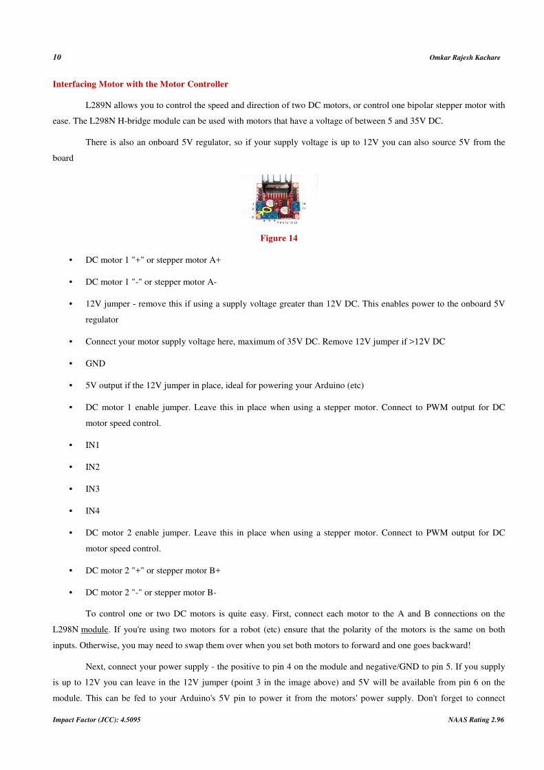
Interfacing Motor with the Motor Controller
L289N allows you to control the speed and direction of two DC motors, or control one bipolar stepper motor with
ease. The L298N H-bridge module can be used with motors that have a voltage of between 5 and 35V DC.
There is also an onboard 5V regulator, so if your supply voltage is up to 12V you can also source 5V from the
board
Figure 14
• DC motor 1 "+" or stepper motor A+
• DC motor 1 "-" or stepper motor A-
• 12V jumper - remove this if using a supply voltage greater than 12V DC. This enables power to the onboard 5V
regulator
• Connect your motor supply voltage here, maximum of 35V DC. Remove 12V jumper if >12V DC
• GND
• 5V output if the 12V jumper in place, ideal for powering your Arduino (etc)
• DC motor 1 enable jumper. Leave this in place when using a stepper motor. Connect to PWM output for DC
motor speed control.
• IN1
• IN2
• IN3
• IN4
• DC motor 2 enable jumper. Leave this in place when using a stepper motor. Connect to PWM output for DC
motor speed control.
• DC motor 2 "+" or stepper motor B+
• DC motor 2 "-" or stepper motor B-
To control one or two DC motors is quite easy. First, connect each motor to the A and B connections on the
L298N module. If you're using two motors for a robot (etc) ensure that the polarity of the motors is the same on both
inputs. Otherwise, you may need to swap them over when you set both motors to forward and one goes backward!
Next, connect your power supply - the positive to pin 4 on the module and negative/GND to pin 5. If you supply
is up to 12V you can leave in the 12V jumper (point 3 in the image above) and 5V will be available from pin 6 on the
module. This can be fed to your Arduino's 5V pin to power it from the motors' power supply. Don't forget to connect

Gyroboard Single Wheel Motorised Skateboard 11
www.iaset.us [email protected]
Arduino GND to pin 5 on the module as well to complete the circuit.
Now you will need six digital output pins on your Arduino, two of which need to be PWM (pulse-width
modulation) pins. PWM pins are denoted by the tilde ("~") next to the pin number
Finally, connect the Arduino digital output pins to the driver module. In our example we have two DC motors, so
digital pins D9, D8, D7, and D6 will be connected to pins IN1, IN2, IN3 and IN4 respectively. Then connect D10 to
module pin 7 (remove the jumper first) and D5 to module pin 12 (again, remove the jumper).
Figure 15
The motor direction is controlled by sending a HIGH or LOW signal to the drive for each motor (or channel). For
example for motor one, a HIGH to IN1 and a LOW to IN2 will cause it to turn in one direction, and a LOW and HIGH will
cause it to turn in the other direction.
However, the motors will not turn until a HIGH is set to the enable pin (7 for motor one, 12 for motor two). And
they can be turned off with a LOW to the same pin(s). However, if you need to control the speed of the motors, the PWM
signal from the digital pin connected to the enable pin can take care of it.
Assembling the Control System.
Once the above phases have been completed the next step is to assemble all the components to test the working of
the dc motor with the sensor interfaced.
The assembly is the mounted on the board to test and calibrate the sensor output relevant to the lean angles of the
board.
The above diagram shows the basic block interfacing of all the control system components.
Fabrication
Machining of Shaft:
The shaft was polished using a lathe machine to fit the inner diameter of the rim and the ball bearings which is
33mm.
Key:
Key fabrication to hold the rim and the shaft together.
Frame:
18mm inches thick ply is used to make the frame.
Drive Train:
The driver and the driven sprockets are welded on the shaft of the motor and the tyre respectively.
12 Omkar Rajesh Kachare
Impact Factor (JCC): 4.5095 NAAS Rating 2.96
The rotational power from the motor to the tyre is transferred using a chain drive
Final Assembly
All the fittings are press-fitted.
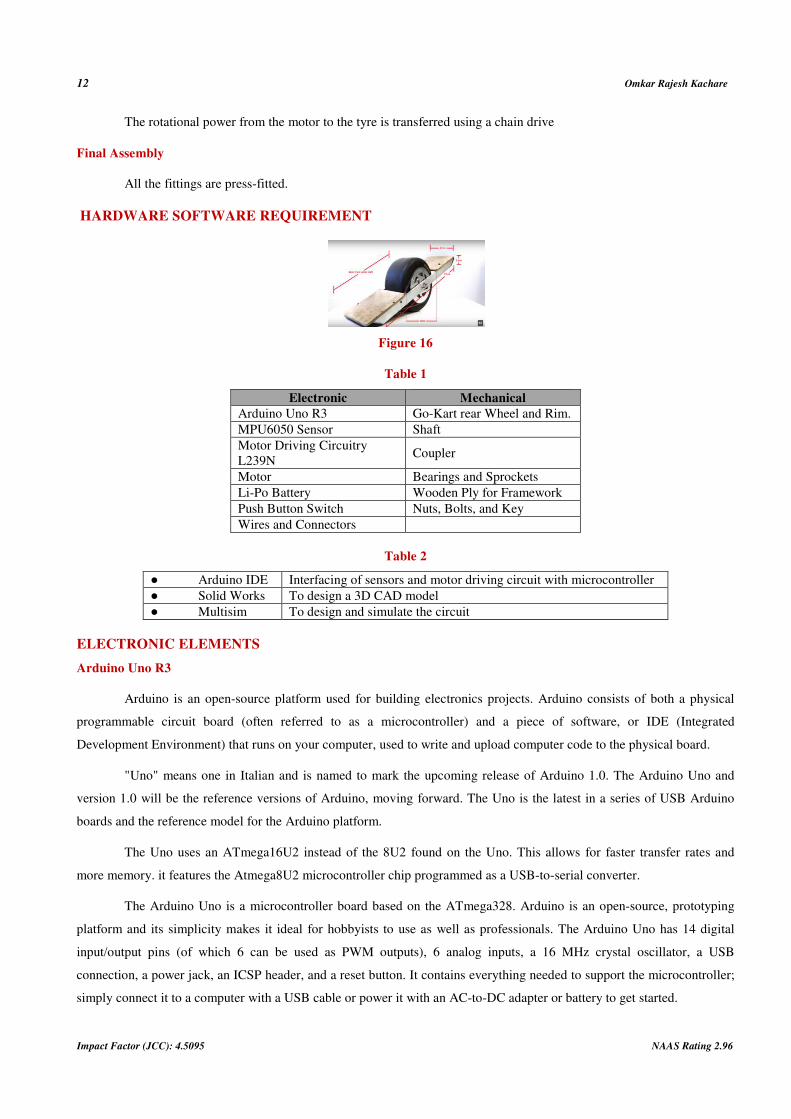
HARDWARE SOFTWARE REQUIREMENT
Figure 16
Table 1
Electronic Mechanical
Arduino Uno R3 Go-Kart rear Wheel and Rim.
MPU6050 Sensor Shaft
Motor Driving Circuitry
L239N Coupler
Motor Bearings and Sprockets
Li-Po Battery Wooden Ply for Framework
Push Button Switch Nuts, Bolts, and Key
Wires and Connectors
Table 2
● Arduino IDE Interfacing of sensors and motor driving circuit with microcontroller
● Solid Works To design a 3D CAD model
● Multisim To design and simulate the circuit
ELECTRONIC ELEMENTS
Arduino Uno R3
Arduino is an open-source platform used for building electronics projects. Arduino consists of both a physical
programmable circuit board (often referred to as a microcontroller) and a piece of software, or IDE (Integrated
Development Environment) that runs on your computer, used to write and upload computer code to the physical board.
"Uno" means one in Italian and is named to mark the upcoming release of Arduino 1.0. The Arduino Uno and
version 1.0 will be the reference versions of Arduino, moving forward. The Uno is the latest in a series of USB Arduino
boards and the reference model for the Arduino platform.
The Uno uses an ATmega16U2 instead of the 8U2 found on the Uno. This allows for faster transfer rates and
more memory. it features the Atmega8U2 microcontroller chip programmed as a USB-to-serial converter.
The Arduino Uno is a microcontroller board based on the ATmega328. Arduino is an open-source, prototyping
platform and its simplicity makes it ideal for hobbyists to use as well as professionals. The Arduino Uno has 14 digital
input/output pins (of which 6 can be used as PWM outputs), 6 analog inputs, a 16 MHz crystal oscillator, a USB
connection, a power jack, an ICSP header, and a reset button. It contains everything needed to support the microcontroller;
simply connect it to a computer with a USB cable or power it with an AC-to-DC adapter or battery to get started.

Gyroboard Single Wheel Motorised Skateboard 13
www.iaset.us [email protected]
Table 3
Microcontroller ATmega328P
Operating Voltage 5V
Input Voltage
(recommended) 7-12V
Input Voltage (limit) 6-20V
Digital I/O Pins 14 (of which 6 provide PWM
output)
PWM Digital I/O Pins 6
Analog Input Pins 6
DC Current per I/O Pin 20mA
DC Current for 3.3V Pin 50mA
Flash Memory 32KB
SRAM 2KB
EEPROM 1KB
Clock Speed 16MHz
Sensor- Mpu6050
The MPU-6000 family provides the world's first integrated 6-axis Motion Processing. The devices combine a 3-
axis gyroscope and a 3-axis accelerometer on the same silicon die together with an onboard Digital Motion Processo
(DMP) capable of processing complex 9-axis Motion Fusion algorithms.
Dimensions: 4x4x0.9mm QFN package
Specifications of Gyroscope
• Digital output X-, Y-, Z-Axis angular rate sensors (gyroscopes) with a user-programmable full-scale range of
±250, ±500, ±1000, and ±2000°/sec
• Integrated 16-bit ADCs enable simultaneous sampling of gyros
• Enhanced bias and sensitivity temperature stability reduces the need for user calibration
• low-frequency noise performance
• Gyroscope operating current: 3.6mA
• Standby current: 5µA
• User self-test
SPECIFICATIONS OF ACCELEROMETER:
Digital-output triple-axis accelerometer with a programmable full-scale range of ±2g, ±4g, ±8g and ±16g
• Integrated 16-bit ADCs enable simultaneous sampling of accelerometers while requiring no external multiplexer
• Accelerometer normal operating current: 500µA
• Low power accelerometer mode current: 10µA at 1.25Hz, 20µA at 5Hz, 60µA at 20Hz, 110µA at 40Hz
• Orientation detection and signaling
• Tap detection

14 Omkar Rajesh Kachare
Impact Factor (JCC): 4.5095 NAAS Rating 2.96
• User-programmable interrupts
Motor Driving Circuit- L298n
The L298 is an integrated monolithic circuit in a 15-lead Multiwatt and PowerSO20 packages. It is a high voltage,
high current dual full-bridge driver designed to accept standard TTL logic levels and drive inductive loads such as relays,
solenoids, DC and stepping motors. Two enable inputs are provided to enable or disable the device independently of the
input
signals.
It is ideal for robotic applications and well suited for connection to a microcontroller requiring just a couple of
control lines per motor. It can also be interfaced with simple manual switches, TTL logic gates, relays, etc.
The circuit incorporates 4 direction LEDs (2 per motor), a heat sink, screw-terminals, as well as eight Schottky
EMF-protection diodes. Two high-power current sense resistors are also incorporated which allow monitoring of the
current drawn on each motor through your microcontroller.
An on-board user-accessible 5V regulator is also incorporated which can also be used to supply any additional
circuits requiring a regulated 5V DC supply of up to about 1A.
The circuit also offers a bridged mode of operation allowing bidirectional control of a single motor of up to about 4A.
Dimensions: 3 x 2.5"
Specifications of l298n:
• Motor supply: 6 to 35 VDC
• Control Logic: Standard TTL Logic Level
• Output Power: Up to 2 A each
• Current Sense Outputs
• Onboard Power Resistors Provided for Current Limit
• Enable and Direction Control Pins
• External Diode Bridge Provided for Output
• Heatsink for IC
• Power-On LED indicator
• 4 Direction LED indicators
• Operating supply voltage up to 46 v
• Total dc current up to 4 Amp
• Low saturation voltage
• Over temperature protection

Gyroboard Single Wheel Motorised Skateboard 15
www.iaset.us [email protected]
• Logical "0" input voltage up to 1.5 v(high noise immunity)
PIN DESCRIPTION OF L298N:
Figure 17
Table 4
Pin 4 Motor supply 24V
Pin 5 GND
PIN 10,11 IN3,IN4 (controlling motor rotation direction)
Pin 12 EN2(used as PWM input for the motor)
DC MOTOR
A DC motor is any of a class of rotary electrical machines that converts direct current electrical energy into
mechanical energy. The most common types rely on the forces produced by magnetic fields. Nearly all types of DC motors
have some internal mechanism, either electromechanical or electronic, to periodically change the direction of current flow
in part of the motor.
The brushed DC electric motor generates torque directly from DC power supplied to the motor by using internal
commutation, stationary magnets (permanent or electromagnets), and rotating electrical magnets.
A geared DC Motor has a gear assembly attached to the motor. The speed of the motor is counted in terms of rotations of
the shaft per minute and is termed as RPM. The gear assembly helps in increasing the torque and reducing the speed. Using
the correct combination of gears in a gear motor, its speed can be reduced to any desirable figure.
RPM CALCULATION
Go-Kart tyre dimension is as follows:
Width: 18.2 cm
Diameter: 28 cm
Circumference = 2*pi*r
= 2*3.14*14
= 88 cm
= 0.88m
1 round → 0.88m
X round → 1000m
Hence,
X= 1136.3 rounds to cover 1 km

16 Omkar Rajesh Kachare
Impact Factor (JCC): 4.5095 NAAS Rating 2.96
~= 1140 rounds/Hr
= 19 rounds/min
For 5km/hr
X=19*5
X=95RPM
Motor calculations:
Power consumed=pin=I*V
Power op of motor=T*W (T=torque, W=angular speed)
W=rpm*2pi/60
W=90*2pi/60
W=9.42rad/sec.
Pout=T*W
250w=T*9.42.
T=(I*V*E*60)/(rpm*2pi)
I=1.35A
Consider,
V=48v
E=15%
RPM=90.
T=103NM
Horse Power=V*I*Eff/746
HP=1.08hp.
Finalmotor specs=
250w,48v,90rpm.
Power Supply
We require 2 power supplies:
• Power supply for the motor
Specs: 48V DC, 1.3 amp
Lead-polymer battery.

Gyroboard Single Wheel Motorised Skateboard 17
www.iaset.us [email protected]
• Power supply for Arduino
Specs: 5V DC, 0.3 amp
5000 mAh, Li-Po battery
DC BATTERY-Li-Po
• 24 V Li-Ion
• Lightweight, low cost
• 100% efficiency
• 100% self -discharge
• More cycle life- 5000 cycles compared to lead -acid battery
• Constant voltage until it discharges
• High current rating
• Eco-friendly- Reduces CO2 emission & recyclable
• Li-Ion cell: 3.9V,2.5 Amp
• Total cells: 6
• Output voltage (Vo)=3.9*6=23.4 V
• Output current (Io)=2 Amp
BATTERY CHARGER
• Input voltage(Vi)=230 V,50 Hz
• Output voltage (Vo)=26.8 V
HARDWARE ISSUES
Electronic Elements
Arduino Uno R3:
Arduino is an open-source platform used for building electronics projects. Arduino consists of both a physical
programmable circuit board (often referred to as a microcontroller) and a piece of software, or IDE (Integrated
Development Environment) that runs on your computer, used to write and upload computer code to the physical board.
"Uno" means one in Italian and is named to mark the upcoming release of Arduino 1.0. The Arduino Uno and
version 1.0 will be the reference versions of Arduino, moving forward. The Uno is the latest in a series of USB Arduino
boards and the reference model for the Arduino platform.
The Uno uses an ATmega16U2 instead of the 8U2 found on the Uno. This allows for faster transfer rates and
more memory. it features the Atmega8U2 microcontroller chip programmed as a USB-to-serial converter.
The Arduino Uno is a microcontroller board based on the ATmega328. Arduino is an open-source, prototyping

18 Omkar Rajesh Kachare
Impact Factor (JCC): 4.5095 NAAS Rating 2.96
platform and its simplicity makes it ideal for hobbyists to use as well as professionals. The Arduino Uno has 14 digital
input/output pins (of which 6 can be used as PWM outputs), 6 analog inputs, a 16 MHz crystal oscillator, a USB
connection, a power jack, an ICSP header, and a reset button. It contains everything needed to support the microcontroller;
simply connect it to a computer with a USB cable or power it with an AC-to-DC adapter or battery to get started.
The MPU-6000 family provides the world's first integrated 6-axis Motion Processing.
The devices combine a 3-axis gyroscope and a 3-axis accelerometer on the same silicon die together with an
onboard Digital Motion Processo (DMP) capable of processing complex 9-axis Motion Fusion algorithms.
Dimensions: 4x4x0.9mm QFN package
Specifications of Gyroscope
• Digital output X-, Y-, Z-Axis angular rate sensors (gyroscopes) with a user-programmable full-scale range of
±250, ±500, ±1000, and ±2000°/sec
• Integrated 16-bit ADCs enable simultaneous sampling of gyros
• Enhanced bias and sensitivity temperature stability reduces the need for user calibration
• low-frequency noise performance
• Gyroscope operating current: 3.6mA
• Standby current: 5µA
• User self-test
MOTOR DRIVING CIRCUIT- L298N
The L298 is an integrated monolithic circuit in a 15-lead Multiwatt and PowerSO20 packages. It is a high voltage,
high current dual full-bridge driver designed to accept standard TTL logic levels and drive inductive loads such as relays,
solenoids, DC and stepping motors. Two enable inputs are provided to enable or disable the device independently of the
input signals. It is ideal for robotic applications and well suited for connection to a microcontroller requiring just a couple
of control lines per motor. It can also be interfaced with simple manual switches, TTL logic gates, relays, etc. The circuit
incorporates 4 direction LEDs (2 per motor), a heat sink, screw-terminals, as well as eight Schottky EMF-protection
diodes. Two high-power current sense resistors are also incorporated which allow monitoring of the current drawn on each
motor through your microcontroller. An on-board user-accessible 5V regulator is also incorporated which can also be used
to supply any additional circuits requiring a regulated 5V DC supply of up to about 1A. The circuit also offers a bridged
mode of operation allowing bidirectional control of a single motor of up to about 4A.
Dimensions: 3 x 2.5"
DC MOTOR
A DC motor is any of a class of rotary electrical machines that converts direct current electrical energy into
mechanical energy. The most common types rely on the forces produced by magnetic fields. Nearly all types of DC motors
have some internal mechanism, either electromechanical or electronic, to periodically change the direction of current flow
in part of the motor.

Gyroboard Single Wheel Motorised Skateboard 19
www.iaset.us [email protected]
The brushed DC electric motor generates torque directly from DC power supplied to the motor by using internal
commutation, stationary magnets (permanent or electromagnets), and rotating electrical magnets.
A geared DC Motor has a gear assembly attached to the motor. The speed of the motor is counted in terms of
rotations of the shaft per minute and is termed as RPM. The gear assembly helps in increasing the torque and reducing the
speed. Using the correct combination of gears in a gear motor, its speed can be reduced to any desirable figure.
SOFTWARE ISSUES
Arduino IDE
The Arduino Integrated Development Environment - or Arduino Software (IDE) - contains a text editor for
writing code, a message area, a text console, a toolbar with buttons for common functions and a series of menus. It
connects to the Arduino and Genuino hardware to upload programs and communicate with them.
Arduino is an open source, computer hardware and software company, project, and user community that designs
and manufactures single-board microcontrollers and microcontroller kits for building digital devices and interactive objects
that can sense and control objects in the physical world. The project's products are distributed as open-source hardware and
software, which are licensed under the GNU Lesser General Public License (LGPL) or the GNU General Public License
(GPL),[1] permitting the manufacture of Arduino boards and software distribution by anyone. Arduino boards are available
commercially in preassembled form, or as do-it-yourself kits.
Inexpensive - Arduino boards are relatively inexpensive compared to other microcontroller platforms.Cross-
platform - The Arduino Software (IDE) runs on Windows, Macintosh OSX, and Linux operating systems. Most
microcontroller systems are limited to Windows. Simple, clear programming environment - The Arduino Software (IDE) is
easy-to-use for beginners, yet flexible enough for advanced users to take advantage of as well. Open source and extensible
software - The Arduino software is published as open source tools, available for extension by experienced programmers.
RESULT ANALYSIS
For an extensive result analysis, we will consider individual components of the gyro board system.
The important components those make ups the gyro board system are
• Arduino controller.
• The motor driver.
Arduino Controller
The Arduino controller is the brain of the gyroboard.
The primary function on the Arduino controller is to get the raw readings of the respective axis and interpret them
for further processing The raw value from the mpu6050 are mapped to processable values. These mapped valued are then
assigned PWM levels.
Arduino has +255 to -255 PWM levels. As the gravitational force acting on the axis of the mpu6050 changes the
assigned PWM value changes.
This can be clearly seen by the PWM output graph of the Arduino controller which is given as follows:

20 Omkar Rajesh Kachare
Impact Factor (JCC): 4.5095 NAAS Rating 2.96
The graph shows the 0 to +255 to -255 PWM level changes as the gravitational force on them changes.
Figure 18
The Motor Driver
The motor driver converts the PWM signal that is given to it as input from the Arduino controller into the dc
voltage which controls the speed and direction of the rotation of the motor.
In our case, the change in the raw values changes the PWM output of the Arduino controller. This change in
PWM, in turn, changes the voltage level of the motor. The change in the voltage level causes the motor to speed up or slow
down. It also governs the direction of the rotation of the motor shaft.
REFERENCES
1. IJCTA, 9(4), 2016,pp.29-34 international Science Press, Designing the mono wheel by using self-balancing
techniques, Sreevaram Rufus Nireekshan Kumar, Bangaru Akash and T. Thaj Mary Delsy.
2. International journal of advance research in electrical engineering, electronics and instrumentation engineering.
Vol. 6, Issue 5, May 2017, Design and development of a self balancing mono wheel electric vehicle. A.Geetha,
Vishwanath Kannan, Akhil Sai Vontimitta, Indraneel Patha
3. International Journal of Science, Engineering and Technology Research (IJSETR), Volume 4, Issue 8, August-
2015 2834 ISSN: 2278 – 7798 All Rights Reserved © 2015 IJSETR, Self Balancing Personal Transporter,
B.Thaseen Kousar, G. Ramesh.
4. https://www.instructables.com/id/Self-balancing-one-wheeled-electric-skateboard.