tractor_1979_bcd-series_om_810134r1-b.pdf - Wheel Horse
36
, , J • • • • •• ·f " .. ". , .. " .. , i , ' . . . PART N O . 8101)4 Rl
-
Upload
khangminh22 -
Category
Documents
-
view
2 -
download
0
Transcript of tractor_1979_bcd-series_om_810134r1-b.pdf - Wheel Horse
, , J •
• •
• ••
·f " .. ". , ..
" .. , i ,
' . . .
PART N O . 8101)4Rl

INDEX Tractor Specifications General Safety Suggestions Vehicle Identification "umbers Owner Registration Card Parts Manual Instruments and Controls
B-Series Tractors C-Series Tractors D-Series Tractors
Operating Your Tractor Safety Interlock System Correct Engine Operation
Starting The Engine (Automatic Transmission ) Sterting The Engine (6 & a .Speed Transm ission ,
Stopping The Engine Throttle Control Choke Control Fuel Specificat ion Oil Specification
Correct Automatic Transmission Operation
To Go Forword To Go Backward To Stop Push Valve Cooling Fan
Correct 6 & 8-Speed Transmission Operation
To Go Forward or Reverse To Change Speeds or Direction To Stop
Correct Tractor Usage B-Series Attachment Mounting
Front and Mid Attachment Hitches e and D-Series
Attachment Belts D-Series C-Series
Operation of the Tractor:
Page •• • •• II,. III
1 2 2 2
3-8 3-4 5-6 7-8
9-11 9
9-10
9
9 10 10 10 10 10
10-11 10 11 11 11 11
11 11 11 11
12-14 12
12 12
12-13 1 2
12-1 3
13-14 With a Mower (All Models) 13 With a Snowthrower (C & D-Series) 13 With a Snow Blade (B-Series) 13 With a Dozer or Grader Blade (C & D-Series) 13 With a Tiller (C & D-Series) 13 With a Plow, Disc, Cultivator, or Harrow (C & D-Series) 14 With Drowbar Type Attachments (All Models) 14
Maintaining Your Tractor Maintenance Checklist
Page
15-26 15
Engine 15-20 Oil Quality 15 Oil level 15-16 Oil Changes 16-17 0;1 F;lter (0-160, 0-200) 17-18 Air Filter 18-19 Spark Plug (s) 19 Breaker Points and Condenser 19 Carburetor Adjustment 19 Fuel Filter 20
Charging and Electrical Systems 20-21 Alternator 20 Main Fuse 20 light Circuit and Fuse 20 Battery 21 light Bulb Replacement 21
Automatic Transmission 21·22 Oil Quality 21 Oil level 21 Oi l Changes 21-22 Oil Filter 22 Cooling Fan 22
a-Speed Transmission 22 Oil Quality 22 Oil level 22
6-Speed Transmission 22 Chassis lubrication 22-23 Foot Broke Adjustment 23-24
6-Speed Models 23 a-Speed Models 23 Automatic Models 24
PTO Clutch & Brake AdjustMent 24-25 B-Series 24 C-Series 24 0-160 25 0-200 25
PTO Clutch Maintenance - D-200 25-26 Seat Adiustment (C & D-Series) 26 Cleaning and Storage 26
Troubleshooting Checklist 27-28 Wiring Diagram - B-81, B-111 28 Wiring Diagram -C-81, C-101, C-121, C-141, C-161, C-171 Wiring Diagram - D-160 Wiring Diagram - D-200
29 30 31
&,CAUTICN & This symbol marks important instructions relating to your personal
safety. To avoid the possibility of injury, read and follow such instructions carefully.
When the manual reFers to the left or right side of the vehicle , it means your left and right when sitting in the driver's seat.

TRACTOR SPECIFICATIONS: ENGINE,
TRACTOR ENGINE RATED MODEl MODEl- H. P.··
B·81 B·191707 8
B·lll B·252707 1 1
C·81 K181S 8
C·l0l K241AS 10
C·121 K301AS 1 2
C·141 K321 AS 14
C·161 K341 AS 16
C· 171 KTl7 1 7
0·160 Q ·B43M·GAO 16 16
0·200 K532S 19.9
·lelter Prefix, . - Brigg s & Slrotto n, K Kohl"" , 0 I. O. plale o.e required to comp le tely identify engine.
"fngine manufacture r' l ral ing 01 3600 RPM.
TRANSMISSION,
B·Series Models
Type,
Number of
Mechanical All Gear
Forward Speeds: 6
Number of
DISPLACEMENT BORE STROKE c ... . in.! cc in .lmm in./mm
19.44/ 318.56 3 / 76.2 2 .75/ 69.9
24.36/ 399. 19 3.438/ 87.3 2.625 / 66.7
18.6/ 304.8 2.94/ 74.7 2 .75/ 69.8
23.9/ 391.6 3 .25/ 82.6 2.88/ 72.9
29.07/ 476.4 3 .38/ 85.7 3 .25/ 82.6
31.27/ 512.4 3 .5 / 88.9 3 .25/ 82.6
35.89/ 588 .1 3.75/ 95.3 3.25/ 82.6
42 .18/ 691.4 3.125/ 79.4 2 .75/ 69. 8
43 .3 / 709 .6 3.25/ 82 .6 2 .62 / 66.5
53 .68/ 879.7 3.38/ 85.7 3/ 76.2
Onan. Batk engine mod",1 number shown ; specification .od uHiol
C-Series a-Speed Models
Mechanical All Gear
6
IGNITION
Magneto
Magneto
Battery
Bottery
Bottery
Battery
Battery
Ba Hery
Battery
Battery
numbers from eng ine
Reverse Speeds: 1 2
Approximate Ground Speeds (a t fulllhrottle) ; Gear
],1
2nd 3,d Rev.
low Range High Range .9 mph (1.4 kph )
1.3 mph (2.0 kph) 1.4 mph (2 .3 kph ) 2.7 mph (4.3 kph)
2 .2 mph (3.6 kph ) 3.3 mph (5.4 kph ) 5.0 mph (8.0 kph ) 2.7 mph (4 .3 kph )
C-Series Automatic Models
Type: Hydrostatic
Number of Forward Speeds : Infinite
Numbe r of Reverse Speeds: Infinite
Approximate Ground Speeds (at full throttle): Variable 0·6.3 mph
(10 kph) Forwc,d Variable 0 ·3 .2 mph (5 .2 kph) Reverse
ELECTRICAL SYSTEM, Type,
Alternator:
Battery:
12 Vol! O.C., Negative Ground Briggs & Stratton - Dual Circuit, 12 Volt, 3 Amp. (Charging Circuit) Onan and Kohler -12 Voll, 15 Amp. B·81, B·lll , C· 81 -12 Volt, 24 Amp. Hr . C·l0l , C·121 , C·141, C·161 , C·171 -12 Volt, 32 Amp. Hr. 0·160, 0·200 -12 Vol!, 45 Amp. H,.
low Range High Range Gear 151
2nd 3,d Rev.
.5 mph ( .8 kph)
.8 mph (1.3 kph) 1.4 mph (2.2 kph )
.6 mph ( 1 kph)
2 mph (3.2 kph ) 3.2 mph (5 .2 kph) 5.5 mph (8.8 kph ) 2.6 mph (4 .2 kph )
D-Series Automatic Models
Hydrostatic
Infinite
Infinite
Variable 0·6.5 mph (l 0 .2 kph ) Forward
Variable 0·3.6 mph (5.8 kph) Reverse
TIRES,
Sizes:
B·8 1
B·ll 1
( ·Series
D·Series
Pressure:
PSI
kg / cm 2
"
Front
13 x 5 ,00·6
13 x 6,50·6
16 x 6,50·8
18 x 8 ,50·8
12
.85
Rear
18 x 8,50·8
18 x 9,50·8
23 x 8,50·12
26 x 12,00·12
1 2
.85

TRACTOR SPECIFICATIONS (continued): PHYSICAL DATA,
TRACTOR MODEL
B-Bl
B· 111
(·81
( · 101
( · 121 a -Speed
( · 121 Automati c
( . 141 . ( · 161 a-Speed
( · 141 . ( . 161 Automatic
(. 171 a -Speed ( · 171
Automatic
D- 160
D·200
HEIGHT
37 In. (94 em) 37 In.
(94 em)
41 In. (104 em)
41 In.
(104 em ) 41 In.
( 104 em)
41 In. (104 em)
41 in. (104 em)
41 in. (104 em)
41 in . 104 em )
41 in . ( 104 ern 45.5 in.
\ 116 ern 45 .5 In .
, 116cm)
lENGTH
65 in . (165 em)
65 in . (1 65 em)
65 in. (165 em)
65 in. (1 65 em)
65 in. t 1 65 em)
65 in. ' 165cm)
65 in. 165 em)
65 in . 165 em)
69 in . 1753 cm l
69 i n . 175 .3 em .
75.5 in ( 192 em) 75.5 in.
(192 em)
WIDTH'
34.5 in. (88 em ) 36 in .
(92 em) 36 in .
(92 em) 36 i n .
(92 em ) 36 in.
(92 em)
36 in . (92 cm l
36 in. (92 em)
36 in . (92 em l 36 in .
(1f2 em)
36 in . (92 em l
45 in. (114 em)
45 in . (114 em )
WHEEl 8ASE
45.5 in. (116 em ) 45.5 in.
(116 em) 45.5 in.
(116em) 45.5 in.
(116 em) 45.5 in.
(116 em )
45.5 in . (116 em) 45.5 in.
(116 em) 45.5 in.
(116 em) 45 .5 in .
(116eml 45 .5 in.
1116 em l
50 in. (127 em)
50 in . (1 2 7 em )
OUTSIDE TURN ING RADIUS
80 in. (203 eml
80 in. (203 em) 75.75 in. (192 em) 75.75 in. (192 em ) 75.75 in. (192 em) 75.75 in. (192 em) 75.75 in. (192 em) 75.75 in. (192 em) 75 .75 in . ( 1 92 em) 75.75 in . (1 92 em)
90 in. 229 em) 90 in.
229 em)
D'V WEIGHT
330 Ib, . 150 kg
350Ib,. 159 kg l
540 Ib,. (243 kg ) 590 Ib, . (266 kg ) 60 0 Ib,. (270 kg ) 630 Ib,. (284 kg) 600 Ib,. (270 kg ) 640 Ib, . (288 kg) 550 Ib,. (249 kg ) 59 0 Ib, . (266 kg l 875 Ib, . (394 kg ) 1025 Ib,. (461 kg )
TUNE-UP/GENERAL MAINTENANCE SPECIFICATIONS: ENGINE,
TRA CTOR MODEL
B·8 1 B· 11 1 ( ·8 1 (· 10 1 ( · 121
(· 141 ( - 161 (· 17 1
D·160 D· 200
POINT GAP
In , mm
.020 ' .5
.020 .5
.020 .5
.020 / .5
.020 / .5
.020 ' .5
.020 .5
.020 .5
.023 .6
.0201.5
TIMIN G MAR K
LOCATION
N A N A
N A
N/ A N/ A N/ A N/ A N/ A
Flywheel Flywheel
'Ot equivolenl (Champion numbe r shown).
LIQUID CAPACITIES ,
Crankcase: B-81 . l Yaqt. (1.1 I) B· ll1 - 112 qt. (1.4 /) ( ·81 - 1).". qt. (1.2 I) ( . 101 - 112 qt. (1.4 1) ( . 121 - 112 qt. ( IAI ) ( · 141 - 112 qt. 11.41) ( . 161 - 1y, qt. (1.4 /) (· 17 1 - 1" , qt. 11.6 I I
IGNITION TIMING (BTDC)
Fixed Fixed Fixed Fixed Fixed
Fixed Fixed Fixed
25 ((old) 27
D· 1 60 - 2 q t. (1. 9 I I w . fi I te' D·200 - 312 qt. (3 .3 I) w / filte,
Transmission: 8 -Series - N / A (.Series a-Speed - 2 qt. ( 1. 9 /) C-Serie s Automati c ~ 5.5 qt. (5.2 I) O-Series - 6 ql. (5.7 I )
Fue l Tank: 8 ·Series ~ 1 Y2 ga l. (5.7 I) ( ·Serie s - 3 gal. (l 1.4 I ) D. 160 - 5 % gol. (21.9 1 ) D·200 - 8 gal. (30.4 I )
SPAR~
PLUG TYPE·
(J·B CJ ·8 J ·8
H· 1 0
H· I O H· l 0 H· l0
Bl· I 5Y
H·8 H· l 0
III
SPARK PLUG GAP
in . ( mm
.030 / 76
.030 .76
.025 .64
.025 / .64
.025/ .64
.025 / .64
.025/ .64 .0 25/ .64 .025 / .64 .035 / .9
CHASSIS ,
Zerk Fittings;
DIRECTI ON OF- ROTATION (Facing PTO)
Cou nterdockwis e Co unterclockwise Counterclockwise Cou nterdockwise Cou ntercloekwise
Counterclockwise Cou ntercloekw ise Co:.;ntcrdoekwise Counterclockwise Counterclockw ise
8 -Se rie s - 6
C-Series - 6
O·Seri es - 7
IDLE oeM
(No loa d)
1750 1750 1900 2100 2 100
2100 2 100
2100 1350 1350
GOVERNED MAX , RPM (No Loa d l
3300 3300 3500 3400 3400
3400
3400 3 400 3600 3600
PTO Brak e Adjustment (PTO engaged): a·Series - .'J10 (. 25 mm ) Gap
between brake pod and pulley
Front Wheel
( -Series - .0 12 (. 3 mm) Gop between broke pod and pulley
D·200 _ .. 012 (.3 mm ) Gap between broke pod and pulley
D· 160 - Refe r to text
End Play: 0- .01 5 in. (.4 mm) All Models
Front Wheel Alignme nt (toe-in ): J..<6-Ya in. (1.6-3 .2 mm) O-Series only

GENERAL SAFETY SUGGESTIONS R~,omme"ded by OUldoor Powe, Equipmenl InJlitute
SAFE OPERATION PRACTICES - RIDING VEHICLES
, . Know the canlro l s and hO\l\f to stop qu ick ly -READ THE OWNER'S MANUAL.
2 . Do not allow ch il dren 10 o perate vehicle. Do nof al low adults 10 operate it wi thout proper instruc t ion .
3 . Do not carry passengers . Keep children and pe ts a safe distance away.
4 . Clear work orea of objects which might be p icked up and throw n .
5 . Disengage a ll attachment clutches and shift inlo neutral before allempling to slor l engine (molor) .
6. Dise ngage power 10 allachment!> and slop en gine (motor) before leaving operator position .
7 . Disengage power 10 allachment (s) and stop en · g i ne (mol or) b e fore making any repa irs or ad justments .
8 . Dise ngage pov..-c r to attachments when IronspOrT ing o r nOI in usc .
9 . Toke a ll possib le precoutions when leaving ve hiclc uno lle nded ; such as disengag ing power · toke -off , lower ing attachments. shifting into neu · trol , setting park ing broke , slopping engine and removing key .
10. 0 0 nol slap or storl suddenly when going uphill o r d o wnhi ll. Mow up and down Ihe foce of steep slopes; never across the face .
11 . Reduce speed on slopes and in sharp turns 10 prevent lipping Or loss of conlrol. Exercise ex· t reme coul ion when changing direclion on slopes.
12 . Stay oler t fo r holes in terroin and other hidden hazard s.
13 . Usc carc when pulling loads or uSing heavy equipment. a . Use only approved drawbar hitch poinls . b . l imil load s to those yo u (an safely (antral c , Do n o t turn sharply . Use core when bo(klng d . Use (ount e rw e ighl (s) or whee l weighls when suggesTed In ow ner's manual.
14. Walch out fo r traffi c when crossing or near rood ways .
15 . When using any ollo(hments never direct di S· charge of molerio l toward bystanders nor a llo w anyone near vehic le wh ile in operation .
16. Hondle gasoline wilh core mabie.
it IS highly f1om -
A. Use approved gasoli ne container . Place con · la iner ou t o f Ihe reach of ch ildren.
B. Use gasoline o n ly as a fu el - never as a cleoner . Ne ver remove co p or o dd gasoli ne 10 a ru nn ing or hal eng ine or fill f uel tonk indoors. W ipe up s p il le d gasohne. Ar,d posi t ive ly NO SMOKING.
C. Open d oo rs if eng ine is run in garoge · e x· ha us t fumes are dangerous. Do no l run en · g ine I motor) indoors.
17 . Keep vehi cle and attachments in good operating co ndit io n and keep safety devices in place .
18 . Keep all nuts , bolts , and scre ws light 10 be sure equipment is in sofe work ing condition .
19. Never slore equipment w ith gasoline in the tonk inS ide a bui ld ing where fumes may reach on o pen nome or spark .
20. Al lo w engine 10 (001 before stor ing In any er1· closu re .
21. To re duce fire hazard keep engine free o f gross , leaves o r excessive grease.
22 . Vehicle and ollo(hmen ls $h oul d be Slopped a nd inspected for damage ofler str ik ing a fo re ign ob ject and the damage shou ld be re paired be· fore resta rt ing and operating the equ ipment.
23 . Do no l chonge engine governo r ~e"in9s or o ver $pccd engine.
24. When us ing vehicle with mower :
( I ) Mow on ly in daylight or in good artificial light.
(2 ) Never make a (utting he ighT odjuslment whi le engine (motor ) is running if operator mu s' d ismount to do so .
(3 ) Shul eng ine (motor) off when unclogg ing chute.
(" ) Check blade mounl ing bo lts for proper tighl ' ness at frequenl interva ls.
25 . C heck gross wtcher bags frequent ly for wear or d e terioralion . Replace with new bogs for sa feT Y protection.
& CAUTION & 1. KEEP ALL SHIELDS IN PLACE. 2. BEFORE LEAVING OPERATOR'S POSITION ,
A. SHIFT TRANSMISSION TO NEUTRAL B. DISENGAGE AND LOWER ATTACHMENTS C. SET PARKING BRAKE D. SHUT OFF ENGINE (MOTORS) E. REMOVE IGNITION KEY
J . KEEP PEOPLE AND PETS A SAFE DISTANCE AWAY FROM MACHINE.
4 . WAIT FOR ALL MOVEMENT TO STOP BEFORE SERVICING MACHINE .
- 1 -
•

•
VEHICLE IDENTIFICATION NUMBER (VIN) LOCATIONS Vehicle identification numbers are used to identify your new tractor o',',d
major attachments. These numbers should always be referred to when consulting your dealer or the factory concerning service, parts, or other information you may require. If these plates ore removed dvring repair operations, they shou ld always be rep laced.
The tractor vehicle identification number plate is located just below the dash ponel.
Engine identification number plates ore located on the engine shrouding and indicate the model, specification or type number and the seriol number of your troctor's engi!1e.
Major attachments olso have a vehic le identification number plate attached to them.
For your convenience and ready reference, enter the tractor and engine numbers below.
B & C Series VIN Plate location
Tractor Identification Number
D-Series VIN Plate location
Engine Identification Number
Model _
Type or Spec No.
Serial No. __ - ------------
OWNER REGISTRATION AND IDENTIFICATION CARD
Service and wa rranty assurance is as important to Wheel Horse as it is to you , the owner. TO ASSURE warranty service at on Authorized Wheel Horse Dealer, Wheel Horse provides an "OWNER IDENTIFICATION CARD" for each new tractor, or mOlor attachment, registered with the factory.
To receive your "OWNER IDENTIF ICATION CARD" either you or your dea ler must fill in the required information on the "NEW OWNER FACTORY REG ISTRATION CARD" and mail immediately. Your "OWNER IDENTIFICATION CARD" will be returned by mail.
I~WHEEL HORSE I lawn & garden tractors
OWNER IDENTIFICATION CARD
PRODUCT 10 NUMBER
SELLING DEALER WAR~A "-I TV EXPIRES
Present thiS card to an aulhC" 1<'- :: )ea.E" 10 Or:t8 111 warranty service
PARTS MANUAL A separate ports manual is available for your Wheel Horse equ ipment.
To obtain a ports manual, see the ordering information found at the end of this publication.
BE SURE TO INCLUDE THE VEHICLE IDENTIFICATION NUMBER OF THE EQU IPMENT.
- 2 -
,

7.-
2.
10.
INSTRUMENTS AND CONTROLS B-SERIES TRACTORS
9. 8 . ~J
- 3 -

1 . THROTTLE CONTROL
The throttle con trol is located on the right s ide of the dash panel. This lever controls engine speed. Ra ise the leve r to operate the troctor; lower the lever to the start the engine.
2. CHOKE CONTROL
The choke conlrol is loca ted o n the left side of the dash ponel. Ra ise Ihe choke lever to the cold start posit ion when storting the engine. Return slowly to
Run p osition after the engine st:J rts . If the engine is worm and hos been running , choki ng may no t be necessary to re!>tort it.
3. IGNITION SWITCH
The ignition switch is loca Te d on the upper portion of the dash ponel, just righ t of center. The igni tion !:o witch hos three positions from left to right : ( 1) Off,
(2) Run, (3) Stort . To stort the eng ine. furn the key
a ll the way to the r ight. Re lease Ihe key when the engi ne storts and it wil l automatica lly return to the Run position. When the switch is turned off, t he e ngine stops and all electrical accenories are turned off.
4. PTO (POWER TAKE-OFF) CLUTCH LEVER
The PTa clutch lever is located on the right side of the tractor, between the parking broke and the brake peda l. Power driven attachments are engaged and disengaged with Ihe PTO lever.
To engage the PTO, push lever fo rward . To d is· engage, pull the lever bock.
The PTa lever actuates a safe ty interlock switch; therefore, the PTO lever must be in the di se ngaged posi tion before the engine will start.
5. PARKING BRAKE LEVER
The park ing broke lever is located In front of the ~ea t to the right of the transmiss ion shift lever.
T a e ngage the parking broke. first apply the foot broke solid ly and then move the parking broke lever bock to lock the brake On.
To re lease the parking brake, push down on the :oot broke. The parking brake lever is spring loaded and wi ll return to t he dise ngaged position when the foot broke is applied.
6. BRAKE PEDAL
The brake pedal is located at the right side of the tracto r. Push ing down o n the pedal applies the brake.
Note: When coming to a stop always depress the clutch pedal as well as the brake pedal so that the transmission will be disconnected from the engine.
7. CLUTCH PEDAL
The clutch pedal is located at the left side of the tractor. Pushing down on the clutch pedal does two things: (1) Oeclutches the tractor drive belt, disconnecti ng the engine from the transmission; (2) Actuates a safety interlock switch, so the starter will operate. Engaging the clutch is done by releasing the pedal which tightens the drive belt. Always release the pedal slowly when engaging the clutch. Always depress the pedal when shifting the transmission into or out of gear and when starting the engine.
8. GEAR SHIFT LEVER
The gear shift leve r is loca ted just 10 front of the seat. Select any of three forward speeds or reverse by moving th e lever to the position indicated on the sh ift pattern decal on the gear shift knob.
9. RANGE SELECTOR
The range selector is localed In front of the seat , just behind the park ing broke lever . Select either high or low range by mov ing the lever forward or rearward to the position indicated on the decal. low range
provides a 2 .6 to 1 speed red uction in each of the three forward gears to provide a slower ground speed. Lavv range app lies on ly to forward speeds. The single reverse speed remains cons tant regardless of the range selector 's position. DO NOT USE A MID-POINT POSITION FOR NEUTRAl. Ne utral must be se lected with the gear shih leveL
10. LIGHT SWITCH (B-1 11 only)
The ligh t svvi,c h is loca ted o n the lower portion of the dash panel, just left of center. Rai se the togg le switch to turn lights o n. lower the switch to tvrn lights off. The lights will work only whi le the engine . . IS running.
11. FUEL SHUT-OFF VALVE (Not Shown)
The fuel shut-off va lve is loca ted at the left side of the hoodstand. The f uel shut -off valve is normally left ope n, except when service on the fuel system
becomes necessary.
4 -

INSTRUMENTS AND CONTROLS C-SERIES TRACTORS
a-SPEED MODEL WITH MANUAL LIFT
10
6+-
AUTOMATIC MODEL WITH HYDRAULIC LIFT
- 5
1. AMMETER
The ammeter is loco ted in front of the operator, just below the dash ponel. The ammeter is a gouge indicating the rate at which the battery is being charged ( +) or discharged (- ).
2. THROTTLE CONTROL
The thrott le control is located on the right sid e of the dash ponel. This le ve r control s e ng ine speed. Rai se the lever fu ll y to operate the trocto r; lower the lever to start the engine.
3. CHOKE CONTROL
The choke control is located on the left side of the dash ponel. Raise the choke lever to the cold stort position when starting the engine. Return slowly to Run position ofter the engine starfs. If the engine is worm and has been running , chok ing may no t be necessary to re stort it.
4. BRAKE PEDAL (S-Speed Models)
The broke pedal is located at the right side of the tractor. Pushing down on the pedal appli e s th e broke. Note: When coming to a stop always depress the clutch pedal as well as the brake pedal so that the transmission will be disconneded from the engine.
S. CLUTCH PEDAL (S-Speed Models)
The clutch pedal is located 01 the left side of the troctor. Pushing down on the dutch pedal does two things : ( 1) Dedutches the troctor drive belt, discon . neeting the engine from the transmission; (2) Actuates a safety interlock switch, so the storter will operate. Engaging the dutch is done by releasing the pedal which tightens the drive belt. Always release the pedal slowly when engaging the clutch. Always depress the pedal when shifting the transmission into or out of gear and when starting the engine.
6. BRAKE/ RETURN TO NEUTRAL PEDAL (Automatic Models)
The brake pedal, located at the left side of the troctar, provides dynamic braking to both rear wheels through the automatic transmission. As the broke pedal is depressed, the transmission is shifted ta ne utral. When the broke pedal is fully depressed, a mechanical brake is also applied for additional braking action. The pedal must be depressed when starting the engine, as the pedal linkage actuates a safety interlock switch, allowing the starter to operate.

7. PTO (POWER TAKE-OFF) CLUTCH LEVER
The PTO clutch lever is located on the right side of the tractor. Power dri ven attachments are engaged and disengaged with the PTO lever. Push the lever forward to engage attachment. Pull the lever back to disengage attachment. The PTO clutch actuates a safety interlock switch in the starter circuit; therefore, the tractor w ill not s tar t unless this leve r is in the disengaged position. If the operator's seat is vacated while the flTO is engaged, a seat switch will automatically shut off the engine.
S. GEAR SHIFT LEVER (S-Speed Models)
The gear shift leve r is located just in front of the seat. Select any of three forward speeds or reverse by moving the lever to the position indicated on the sh ift pattern decal on the gear shift knob.
9. RANGE SELECTOR (S-Speed Models)
The range selector is located in front of the seat, just forward of the gear shift lever. Se lect either high or low range by moving The lever ri ght or left to the position indicated on the decal on the shift knob. Low range provides a 4 to 1 speed reduction and greater pul ling powe r for moving heavy toads in each of the three forward speeds and reverse. Do not use a mid-point position for neutral; neutral must be selected with the gear shift lever.
10. MOTION CONTROL LEVER (Automatic Models)
The motion control lever is located ju st right of the steering wheel. Push the lever ahead to drive the tractor forwa rd. Pu ll the lever back for reverse. Move the lever to the neu tro l (center) position to stop. The brake pedal moves the lever to the neutra l position for dynamic brak ing. The conlrol lever varies ground speed and pulling power of the tractor independent of engine speed. To increase ground speed, move lever away from neutral. Increase pulling power by moving leve r toward neutra l. The neutral pos ition is provided w ith a detent type stop to give a 'perceptible feel ' as the contro l lever posses through neutral.
11. PARKING BRAKE LEVER
The parking broke lever is located in front of the seat to the left.
To engage the parking brake, first apply the foot broke solidly and then move the parking broke lever back to lock the broke On.
To release the porking brake, push down on the foot broke. The parking lever is spring loaded and will return to the disengaged position when the foot brake is applied.
12. TRANSMISSION CLUTCH LEVER (Automatic Models)
The transmission clutch lever is located between the seat and the motion control lever. The transmission clutch lever disconnect s the engine from the tra ns -
mission. Pull the lever up and to the rear to disconnect the transmission.
Push the lever forward and down to engage the transmission.
Always disengage the transmission when starting the engine in cold weather.
13. MANUAL LIFT LEVER (S-Speed Models, C-121 Automotic)
The manual lift lever is located just left of the steeri ng wheel. Depress the release button and move the lever forward or backward to lower or raise attachments used with the Iractor. When it is desired to hold an attachment at a certain height above the ground, the forward (dawn) tra vel of the lever can be limited by the Dial · A-Hite selector. Turn t he hand knob right or left until the lift lever is he ld in the desired position. Always lower attachments before leaving the tractor unattended.
14. HYDRAULIC LIFT LEVER (C-171 , C-161, C-141 Automatic)
The hydraulic lift lever is loca ted on the lower dash panel , just below the choke control. Pull the lever back to lift attachment. Release lever to hold attachment in position. Push lever forward to lower attachment. The neutral position will hold on attachment at any position from full up to full down. Always lower attachments before leaving the tractor unattended.
15. LIGHT SWITCH (C-171, C-161, C-141, C-121 only)
The light switch is located on the lower portion of the dash panel, just left of cente r. Raise toggle to turn on lights . lower toggle to turn lights off. lights work only when the ignition swi tch is in the Run position.
16. IGNITION SWITCH
The ignition switch is located on the upper portion of the dash panel, just righl of center. The ignition switch has three positions from left to right: (1) Off, (2) Run , (3 ) Start. To start the engine, turn the key all the woy to the right. Release the key when the engine storts and it will automatically return to the Run position . When the switch is turned off, the engine stops and all electrica l accessories are turned of!.
17. FUEL SHUT-OFF VALVE (Not Shown)
The fuel shut-off valve is located at the bottom of the fuel tank. The fuel shut·off valve is normally left open, except when service on the fuel system becomes necessary.
IS. FUEL GAUGE AND VENT CAP (Not Shown)
The gas cop is designed with a built-in fuel level gouge. Always make sure the vents in the cap are open.
- 6 -

INSTRUMENTS AND CONTROLS D-SERIES TRACTORS
1 4
6
r(.",, _ ,...,, ~ -
J . .... - ~
. , . . ,
10
, ,
0- '60 AUTOMATIC
3
0 -200 AUTOMATIC
1. AMMETER
The ammeter is located o n the upper left portion of the dash ponel. The ammeter is a gauge indicating the rate at which the battery is bei ng charged (+ ) or di scharged (-).
2. TRANSMISSION OIL TEMPERATURE GAUGE
The transmission oil temperature gouge is loca ted on the upper right portion of the dash panel. This gouge serves as on indicator of transmiss ion overload or
7
poss ible malfunction. Operating in the yellow range shou ld be done only for short periods of time . Operating in the red (above 250 -' ) should be strictly avoided.
3. ENGINE OIL PRESSURE GAUGE (0-200 only)
The engine oil pressure gauge is located on the lower right port ion of the dash ponel. This gauge gives o n indication of engine condition. The oil pressure reading should be 45 to 65 P.S. I. at full throttle with the engine at operoti ng tempe ra ture.

4. CHOKE CONTROL
The choke control is located on the left side of the dash pane l. Move choke leve r forward to the cold start position when starting the engine. Return slowly to the Run position after the engine starts. If the engine is warm and has been running , choking may not be necessary to restart it.
5. THROTTLE CONTROL
The th rottle control is located on the right side of the dash ponel. This lever controls engine speed. Move the lever forward to operate the tractor ; pull lever bock to start the engi ne .
6. BRAKE, RETURN TO NEUTRAL PEDAL
The brake pedal, located on the left side of the tractor, provides dynamic braking to both rear wheels through the automatic transmission. As the broke pedal is depressed, the trans mission is sh if ted to neutral. When the broke pedal is fully dep ressed , a mechanical brake is also applied for additional braking action. The brake pedal must be depressed when starting the engine, as the pedal linkage actuates a safety interlock switch, a llowing the sto rter to opera te .
7. PTO (POWER TAKE-OFF) CLUTCH LEVER (D-200 only)
The PTO clutch lever is locoted just left of the steering wheel. Power driven attachments are e ngaged and disengaged with the PTO lever. Push lever forward to engage attachment. Pull lever back to disengage attachment. The PTO clutch lever actuates a safety interlock switch in the starter circui t; therefore, the lever must be in the disengaged position to start the engine. If the operator's seat is vacated while the PTO is engaged, a seat switch will automatically shut off the engine.
8. PTO (POWER TAKE-OFF) CLUTCH SWITCH (0-160 only)
The PTO clutch switch is located directly in front of the operator on the lower control panel. Engagemen t and disengagement of power driven attachments is controlled by the PTO switch. By raising the switch to the On position power dri ve n a tta ch. ments are immedia tely engaged. Returning the switch to the Off position disengages attachments. The tractor will NOT start with the PTO switch in the On position. If the operator's seat is vacated while the PTO is engaged, a seat switch will automatically shut off the engine.
9. MOTION CONTROL LEVER
The motion control lever is loca ted just right of the steering wheel. The motio n control lever may be moved up and down in the neutral slot. Push the leve r down and ahead to ga forward. lift the lever up and pull back to reverse. The brake pedal moves the con trol lever to neutral for dynamic braking. The cont rol lever varies ground speed and pulling power independent of engine speed. To increase ground speed, move lever away from neutral. Increase pulling power by moving lever toward neutral.
10. PARKING BRAKE LEVER
The parking brake lever is located just below the lower control panel, directly in front of the operator. To engage the parking brake, depress brake peda l and pull the parking brake lever up and to the left. To disengage, depress the brake pedal and push lever to the right and down.
11. HYDRAULIC LIFT LEVER - Mid Lift
The mid hydraulic lift lever is located on the left side of the lower control panel. The handl e points to the outside of the tractor. The mid lift lever (lef t lever) operates attachments connected to the mid lift such as the mid mount mower and the snowthrower. OPERATION : Move lever up to lift attachment. Release lever to hold attachment in posi tion. Push lever down to lower attachment. The neutral position will hold the attachment at any position from fuJI up to full down. Always lower attachment before leaving the Iractor unattended.
12. HYDRAULIC LIFT LEVER - 3-Point Hitch
The 3-point hitch hydraulic lift lever is located on the left side of the lowe r control panel. The handle points to the inside of the tractor. The 3-point hitch lever (right lever) operates the optional 3-point hitch. OPERATION: Move lever up 10 li ft the attachment. Release lever to hold attachment in posit ion. Push lever down to lower attachment. The neutral position will hold the attachment at any position from full up to full down. Always lower attachment before leaving the tractor unattended.
13. LIGHT SWITCH
The ligh t switch is located on the lower control panel, just to the righ t of center. Raise toggle to turn on lights . lower togg le to turn lights off. lights work only when the ignition switch is in the Run position.
14. IGNITION SWITCH
The ignit ion switch is located on the right side of the lower con t rol panel. The ignition switch has three positions from left to right : ( l ) Off, (2) Run , (3) Start. To start the engine, turn the key all the way to the right. Release the key when the engine sta rts and it will automatical ly return to the Run position. When the swi tc h is turned off, the engine stops and all electrical accessories are turned off.
15. FUEL GAUGE AND VENT CAP (Not Shown)
The gas cap is designed with a built-in fue l level gauge. Always make sure the vents in the cop are open.
16. FUEL SHUT-OFF VALVE (Not Shown)
The valve is located at the bottom of the fuel tank and is accessible from the rear of the tractor. The fuel shut-off valve is normally left open, except when service on the fuel system becomes necessary.
- 8 -

OPERATING YOUR TRACTOR SAFETY INTERLOCK SYSTEM
The safety interlock system incorporates two
switches, for safe starling.
The two starting switches are actuoted by the left foot pedal and the PTO clutch control. If the tractor will not start, check thot the PTO clutch is disengaged, cnd the left foot pedal is depressed. The engine will
not start un less both switches are properly actuated. C and D-Series tractors ore equipped with a seat
switch. This switch shuts off the engine if the driver rises off the seot while the PTO is engaged.
CORRECT ENGINE OPERATION
8,. CAUTION 8,. Before starting the engine, become familiar
with all controls. Read this owner's manual thoroughly_ Always check the engine oil level before starting. Always check the tronsmission oil level (automatic transmission models) before starting.
WARNING Care should be taken to avoid inhaling ex
haust gases as they contain carbon monoxide gas which is colorless and odorless. Carbon monoxide is a dangerous gas that can cause unconsciousness and is potentially lethal.
Do not run the engine in confined areas such as a closed garage.
STARTING THE ENGINE
(Automatic Transmission Models)
Because of a buil t-in safety interlock system, your new Wheel Horse will not start until the broke pedal IS depressed and the PTO is disengaged.
To start the eng ine depress the broke pedal and
disengage the PTO. Move the throttle control lever
about half way to the Operote position. Move the
choke control 011 the way to the Cold Start position.
Turn the ignit ion key clockwise until the starter
engages. When the engine starts, release the key. The switch is spring loaded and will return to the Run position automatically.
--If the engine fails to start after 30 seconds
of continuous cranking, turn the key to the Off position and allow the starter motor to cool. Check for cause of hard starting; consult the Troubleshooting Checklist.
Once the engine has started, slowly return the choke control bock to the Run position. If the engine sto lls at low speeds. or hesitates during acceleration, the
choke should be applied as necessory until the engine
reaches normal operating temperature.
When starting the engine during cold weather,
be sure to follow the special procedures for worming up the engine and the transmission as described under "Correct Automotic Transmission Operation", before placing the tractor into operation.
STARTING THE ENGINE
(6 & B-Speed Transmission Models)
Because of a built -in safety interlock system, your new Wheel Hor!>e will not stort until the dutch pedal
is depressed and the PTO is disengaged.
To start the engine depress the dutch pedal and
disengage the PTO. Raise the throttle control lever about half way up. Raise the choke con lrol all the way up.
8,. CAUTION 8,.
Always place the transmission gear shift lever in the neutral position before attempting to start the engine.
Turn the ignition key clockwise until the starter engages. When the engine storts, release the key.
The switch is spring loaded and will return to the
Run position automatically.
If the engine fails to start after 30 seconds of continuous cranking, tUrn the key to the Off position and allow the starter motor to cool. Check for cause of hard starting; consult the Troubleshooting Checklist.
Once the engine has started. slowly push the choke control back to the Run position. If the engine stalls at low speeds, or hesitates during acceleration, the choke should be applied as necessary until the engine
reaches normal operating temperature.
9 -

STOPPING THE ENGINE
To stop the engi ne , re turn the thro tt le lever to the Stort o r Slow pos ition and tu rn the ignitio n key to the Off pos iti o n. If th e e ngi ne has bee n working hard , o r the e ngi ne is hot, a llow the e ng ine to id le a sho rt time bef ore tu r ning the key o ff, Th is p roct ice w ill hel p to cool the e ng ine be fo re stopp ing .
Note: In cose of emergency, the eng ine may be stopped by tu rni ng the ign iti o n key to t he Off positio n .
&CAUTION &
Always remove the key and set the parking brake when leaving the trador unattended, even if for just a few minutes. Prevent accidents, don't give children or unauthorized pe rsons an opportunity to operate this machine.
THROTTLE CONTROL
The throttle con trol regulates the speed of the engine as measured in RPM (Revo lutions Per Minute) . This conlro! should not be u!>ed to regula te the g rou nd speed of the trac tor.
The e ngine in your new Wheel Ho rse has been d es igne d wi th a special govern or t hat lim its ma xim um RPM. Unl ike an automobile , this governo r a llow!> th e engine to opera te most efficiently a t a set !>peed, a nd protect !> it from damage caused by exce!>s ive RPM. Always o pera te the Iractor wi th the th rottl e control set at % to full speed.
The engine MUST be operating at a minimum of ~4 throttle whenever the tractor is in use. Using the tractor while the engine is operating at less than % throttle may result in extensive transmission damage on automatic models, as well as poor overall tractor performance on all mode ls.
CHOKE CONTROL
The choke co ntrol act ivates a "b u tt e rfl y" valve in the ca rbureto r. Th is va lve lim its the a mo un t o f ra w ai r avai la ble to the carbure to r. If the choke is Ope n the carbure tor has an unrestr ic ted flow of row a ir. If t he choke is Closed , t he a mou n t of raw a ir ava ilab le is lim ite d , th us caus ing the inta ke of the e ngine to d raw a hig her fue l-to-a ir mixt ure from the ca rbu re tor.
Choking the e ng ine is req uire d w hen the e ngine is starte d co ld . Wa rm e ngi nes may no t need choking.
FUEL SPECIFICATION
When the t ra ctor req ui res refueling, fil l the tan k wi th a good g rade (90 octa ne minim um) of regu lar or un leade d gaso line. Do not intermix regular and unleaded gasolines. Do not mix oil with gasoline.
&CAUTION & Handle fuel with care - it is highly flam
mable. Use only approved fuel container. Never add fuel while the engine is running. Fill fuel tank outdoors with extreme care. Never fill fuel tank indoors. Replace gasoline cap securely and wipe up all spilled fue l.
OIL SPECIFICATION
To protect you r ne w W heel Ho rse, check the engi ne oil leve l before eac h use. Fo r maxim um pro te cti on under all operati ng condi tio ns use API Service Cla ssi fica ti on "SE" o il in t ra ctors equ ipped with O nan engines, a nd API Se rvice Classi fi cati o n " SC" (fo rmerly "MM"), "SO" (forme rl y "MS"), or "SE" o il in tracto rs equip ped w ith Briggs & Stratton or Ko hler e ng ines. These letters may appear o n the oil ca n si ngularly or in comb inat ion with other letters.
CORRECT AUTOMATIC TRANSMISSION OPERATION
During cold weathe r, start the engine with the parking brake engage d; on C-Series models also lift up the transmission dutch lever. Run the engine at full throttle for two minutes to allow engine to warm-up and then engage the transmission clutch by pushing the lever down. For temperatures between 0 and 30'"' F (- 18'" and -2 '- C) allow the transmission to run in neutral for 5 minute s before attempting to set the unit into motion. For temperatures below OOF (_18 °C) allow the transmission to run in neutral for 10 minutes before attempting to set the unit in motion . Failure to do so may result in extensive inte rnal transmission damage.
TO GO FORWARD
&CAUTION & Before the tractor will move either forward
or backward, the parking brake must be dise ngaged. ALWAYS depress the brake / return to neutral pe dal when disengaging the parking brake.
The mot io n of you r tractor is con tro ll e d by a s ing le " Motio n Contro l l ever" . To go fo rward , sim ply push the leve r forwa rd . The farther fo rward the leve r IS pushed, the faster the Iractor wi ll go.
&CAUTION & For safe operation, never move the motion
control lever too rapidly, especially on grades.
By ad just ing the moti o n control le ver, the forward speed of the tracto r ca n be regulated without adjust ing the e ng ine thrott le con trol. Fo r hea vy pu lli ng , mov ing the con trol lever towa rd neutra l red uces tracto r grou nd spee d a nd increa se s pulling power much the some as shi fting to a lo we r gea r w ith a mecha n ical tra nsmiss ion.
10 -

TO GO BACKWARD
To reve rse the motion of th e tractor, return the motion control lever to the neutra l position, and pull the lever back. The farther bock the lever is the faster th e tractor will go in reverse.
&. CAUTION &. For safe operation, never move the motion
control lever too rapidly, especially on grades.
By odjusting the motion contro l lever, the reverse spe ed of the troctor co n be regula ted without adjustIng the engine throttle control.
TO STOP
Stopping the tractor from either the forward o r reverse direction con be ach ieved by one of tw o methods;
1. Return the motion con trol lever to its neutral position.
2. Dep ress the brake pedal.
Activating the brake pedal automatically re tur ns the motion control lever to its neutral position and applies a mechanical brake. The b rake pedal w ill hold th e motion control lever in th e ne ut ral position. The p edal must be released b e fore the motion control lever can be moved e ither forward or bock.
The troctor is stopped by a "dynamic braking" action inside th e hydrostatic t ransmiss ion and a mechanica l brake. The tracto r may have a slight tendency to ro ll when stopped o n a slope, if the motion cont rol lever has bee n used to stop the tractor.
When operating your tractor on a slope the trattor can be stopped from rolling by depressing the brake pedal.
PUSH VALVE
Because o f the "dynamic broke" feature of th e hydrosta ti c transmission, the tracto r can be pushed for only a few feet before th e rear wheels w ill lock . If for some reason the tractor must be pushed., th e manual bypass Push Valve must be opened. The va lve is located o n the left side of the tra ctor above the footrest on D-Se ri es t ractors, and inboard of the left rear wheelan ( -Se ries trac tors. To operate t he valve, follow the instructions on th e " push valve" decal. The va lve has a squa re head and can be opened or closed with a wrench. Be sure to close the valve before operating the tractor.
Push Valve (C-Series Shown)
Hand push tractor only. Do not tow. Towing can cause severe damage to the hydrostatic transmission.
COOLING FAN (D-Series Only)
O·Ser ies tractors are equipped wi t h a fon that he lps keep the transmission ru nning cool. The fan is controlled by a the rmos ta t that turns the fon on after the transmissio n worms-up. The fan will operate 01-most continuously during warm wea ther. The fan may cycle on and o ff dur ing cold weather operation.
CORRECT 6 &. 8-SPEED TRANSMISSION OPERATION
TO GO FORWARD OR REVERSE
With the e ngine running , depress both the clutch and the brake pedal s. Move the range se lector to either the High or the Low position. Move the gear shift lever to the desired speed forward, or to reverse . The gear shi ft knob identifies the var ious speeds. Release the brake peda l. Slowly release th e clutch peda l. As the clu tc h peda l is re leased, the traclor wi ll beg in to move.
&. CAUTION &. Always release the clutch pedal slowly when
starting the tractor in motion . Sudde n starts can be damaging to the equipment and could cause loss of operator control.
TO CHANGE SPEEDS OR DIRECTION When a change in ground speed or direction is re
quired, o lways bri ng th e tractor to a com plete halt by depress ing both the -c lutch and the brake p e dals.
Never aHempt to shift gears with the unit in motion . Severe internal transmission damage may result.
Change either the gear shift lever or range selector as desired. The approximate ground speed for each gear is shown in th e specifications in th e front of this ma nua l.
It is not necessa ry or recommended to s hift " up" or "d own" through th e gears w it h the tractor in motion. The tractor has sufficient power to move out in any gear. If the traclor wil l not move out in a selected gear with a hea vy load attached, a lower gear should b e used.
TO STOP To stop the tractor, depress the clu tch pedal , then
the brake ped a l. The clutch pedal must be depressed fully before the brake pedal is depressed.
&. CAUTION &. When stopping the tractor always depress the
dutch pedal first , then the brake pedal . Depress~ ing the brake without the dutch may cause excessive brake lining wear, or extensive internal transmission damage. Depressing the clutch pedal without depressing the brake pedal Will NOT STOP THE TRACTOR.
- II -

CORRECT TRACTOR USAGE &CAUTION &
Read the manuals provided with the aHachments before operating. The manuals give a more detailed description of operation and point out other areas of caution.
Familiarize yourself thoroughly with the equipment before attempting to use it.
B-SERIES ATTACHMENT MOUNTING
B-Series attachments are designed for easy installation and removal. Refer to the manual supplied with each attachment for mounting instructions.
FRONT AND MID A TT ACHMENT HITCHES C and D-SERIES
Tach-a -matic front and mid hitches ore provided for easy installation and removal of attachments without tool s.
To install attachments make sure the hitch latch is in the released position - 10 do this, push in on the lock relea se pin; move the latch lever so the latch is open and release the lock pin to hold the latch in the o pen position. Insert and center the attachment shaft in the hitch slots and move the latch toward the closed position until the release pin snaps outward.
Removal of the attachment is done by pushing in on the lock release pin , which a llows the lotch to be moved to the open posi tion.
Note: For specific installation and removal instruc tions refer to the attachment instructions.
FRO NT HITCH HANDle
HITCH SLOT
lOCK RELEASE PIN
MI D HITCH .",.,<11
Front and Mid Attachment Hitches (C-Series)
fRON t HII CH So-iCWN OPt N MID "'IICH ,"<OWN ClO~f.O
Front and Mid Attachment Hitches (D-Series)
ATTACHMENT BELTS D-SERIES
Attachment belts are installed and removed on the front PTO pulley after removing the front grille. To remove the grille proceed as follows.
Note: The grille is located near the mufflers and e ngine where considerable heat is generated; therefo,e. BE SURE THAT THE GRILLE IS COOL ENOUGH TO HANDLE.
Removal : Grasp grille with the two knobs provid ed. lift up to compress the grille spring permitting the bottom of the grille rods to come out of their seating holes. Pull the bottom of the grille forward and remove the top of the grille rods from their sealing holes at the top of the grille shroud.
PTO Belt Installation (D-Series)
C-SERIES 1. Remove hairpin cotter from the trunnio n and lift
the trunnion out of the top plate. 2. Remove clev is p in from the clutch shaft and
clevis . 3. Move the top plate forward and move the pul
ley assembly in toward the engine enabl ing the clevis to clear the clutch shaft; swing clutch rod ho usi ng (yoke) to the rear .
4. Instol1 attachment belt .
PTO Belt Installation (C.Series)
- 12 -

5. Swing the clutch rod housing (yoke) to the Front unt il the clevis lines u p w ith the clu tch shaft . M o ve the top plate to the rear. line up the clevis wi th the hole in the clutch shoft and install clevis p in.
6. Insert trunnion in the top plate and secure with the hairpin cotter. IF the rod-to-plate spri ng has become disengaged reconnect spr ing.
OPERATION OF THE TRACTOR: Because of the power of the tractor, no problem
should be encountered using these a ttachments unde r normal conditions. On rough , hilly, or wet terrain, the addition of wheel weights (C & D-Series only) ond tire chains (all models) will minimize rear tire slippage.
WHEE L HORSE DOES NOT RECOMMEND ADDING ANY OTHER WEIGHT, SUCH AS WATER OR CALCIUM CHLORIDE, TO THE REAR TIRES. THIS ADDITIONAL EXTRA WEIGHT CAN CAUSE EXTENSIVE TRANSMIS· SION DAMAGE.
WITH A MOWER (All Models)
&. WARNING &. Keep all shie lds and mowe r discharge chute
in place. Never attempt to cle a r discharge a reas or mowe r blades without disengaging the PTO clutch and re moving the ignition ke y_
For best operation o n average lawns, operate the engine at full throttle while controlling the ground speed with the transmission. The tractor should be opero ted at 2 to 3.5 MPH (3.2 to 5.6 KPH )* while mowing gross. Uneven cutting is often the result of excessive ground speed. To correc t, reduce the ground speed with the transmiss ion . Average lowns are usually cut ot a height between 2 and 3 in . (5-7.6 cm). Toll grass and weeds should be cut with the mower in it's highest position, making a second pass cutting to the heigh t desired.
Always keep the mower b lades sharp.
WITH A SNOWTHROWER (e & D-Series)
&, CAUTION &. Thoroughly in sped the are a whe re the snow
thrower is to be used . Re move all door mats, sled s. boards and other foreign obje cts. Never ma ke any ad justments while t he e ngine is run. ni ng _ Never t ry to clear the chute while the e ngine is runn ing .
Snow removal will vary grea tly with the condition of ea ch snowfall . light fluffy snow will be cleared wi th ease. Heavy wet snow will be more difficult. It is advisable to coot the auger and chule wi th a ligh t coa t of wax or paraffin to keep snow from sticking. Best results are usually attained when the t ractor ground speed is sel at 1 to 2 MPH (1.6 to 3.2 KPH l_*
Experience will teach you not to throw snow in to the wind .
Care shou ld be exercised whenever the snowthrower is engaged. The auger is capable of p icking up sticks, stones and other foreign objects and expe ll ing the m wi th g rea t veloci ty . A lways aim the d is· charge chute a way From persons or ob jects subject to harm_
Tire chains a nd wheel weig ht s are recommended for use with the snowthrower.
WITH A SNOW BLADE (B-Series) The front end snow blade is used for snow removal.
Core should be taken and a slow ground speed should be maintained whe never the blade is used. Impact with a solid object may resu lt in injury to the operalar and / or damage to the blade.
Tire chains may be added to im p rove rear tire traction.
WITH A DOZER OR GRADER BLADE (e & D-Series)
Although the fron t end dozer b lade is genera ll y used fo r snow removal , it can also be used for moving dirt, sand or g ravel. Core should be token and a slow ground speed should be maintained whenever the blade is used. Impact with a so lid object may result in injury to the operator and / or damage to the blade.
Grader b lades are generally preferred for leveling sand, dirt or gravel. The operation of these blades is similar to that of a dozer b lade_ Rear mount grader b lades may requ ire special rear hitches; consult your dealer far the prope r hifch (es) reqUired for your tractor.
When using any of these attachments w ith the trac tor, front whee l weights shou ld be used to increase fron t whee l traction. Rear wheel weigh ts and tire chains may also be used to increase rear whee l traction.
WITH A TILLER (e & D-Series)
The Wheel Horse tiller does an excellent job of preparing gardens for planting .
D-Series tracto rs require a 3-point hitch and rear PTO (dealer installed options) for moun ting a ti ller.
Caution should be exercised when tilling virgin ground or clay as the tiller may have a tendency to push the tractor. This can be corrected by raising the tiller with the attachment lift so the tiller penerotes o nly the very top of the soil. The tiller con be lowered to ils fu ll depth on Following passes.
&, CAUTION &. If the tille r sta rts to push the tractor, shut
the tille r off imme diate ly by di sengaging the PTO clutch.
Reor wheel weigh ts and clea t tires or tire chai ns will reduce the pushing effect of the tiller.
Front wheel weights are recommended to Improve the steer ing of the troctor .
The slower the tractor's ground speed, the more aggressive the action of the tiller. Best results are usually attained when the tractor ground speed is se t at less than 1.0 MP H (1.6 KPH ).*
Do not over-tiJi the soil. Soil filled excess ively will no t hard water, and will compact easily.
• Average walking speed is 2.5 MPH (4 KPH).
13 -
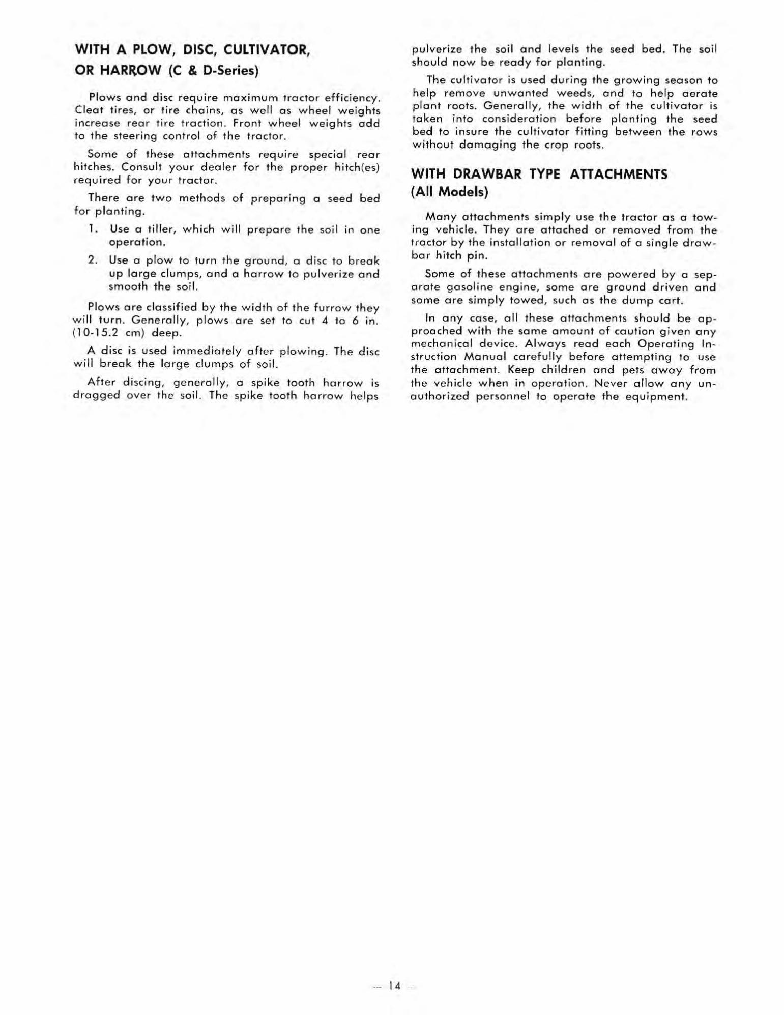
WITH A PLOW, DISC, CULTIVATOR,
OR HARROW (C & D-Series)
Plows a nd disc require maximum fractor efficiency. Cleat tires, or fire chains, as well as wheel we ights increase rear ti r e traction . Front wheel weights odd to the steering control of the tractor.
Some of these attachments requ i re special rear hitches. Consult your dealer for the proper hitch (es) required for your tracto r.
There are two methods of preparing a seed bed fo r planting.
1. Use a tiller, wh ich w ill prepare the soil in one operation.
2. Use a plow to turn the ground, a di sc to break up la rge dumps, and a harrow to pulverize and smooth the soil.
Plows are c la ssified by th e width of the furr ow they wi ll turn. General ly. plows o re set to cu t 4 to 6 in. (10-15.2 em) d eep.
A disc is used immed ia tely after plowing . The disc will break the large clumps of soi l.
After discing . generally, a spike tooth harrow is dragged over the soil. The spike tooth harrow helps
pulverize the soi l and levels the seed bed. The soil shou ld now be ready for planting.
The cultiva tor is used during the growing season t o help remove unwonted weeds, a nd to help aerate plan t roots. Gene ra ll y. the wid th of the cultivator is taken into consideration before planting t he seed bed to insure th e cult ivator fitting between th e rows wi thout damaging the crop roots.
WITH DRAWBAR TYPE ATTACHMENTS (All Models)
Many attachments sim ply use the tracto r as a towing vehicle. They are attached or removed from the tractor by the insta llation or remova l of a single drawbar hitch pin.
Some of these attachments are powered by a separate gasoline eng ine, some are ground dri ven and some are simply towed, such as the dump cart .
In any case, all th ese attachments should be app roached wi th the same amount of caut ion given any mechanica l device . Always read each Operat ing In struction Manual carefully before attempting to use th e attachment. Keep children and pets away from the vehicle when in opera tion. Never allow a n y unau thor ized personnel to operate th e equipment .
-- 14 -

MAINTAINING YOUR TRACTOR & CAUTION &
To minimize the chance of injury, perform all maintenance and adjustments on your tractor with the engine off and ignition key removed, unless instructed otherwise in this section. Use extreme care when working near operating machinery. Remove watch and jewelry before beginning work and observe common safety practices when using tools.
MAINTENANCE CHECKLIST
SERVICE OPERATION
Check.
Engine Oil Level Battery Water leve l
Transmission Automatic
Oil level Manual Tire Pressures
Tightness of all Attaching Hardware
Cleon Engine Cooling Fins Clean Transmiss ion Cooling
Fan (O-Series)
Clean Air Filter B-Series, D· 160 (-Series, D· 200
lubricate Chassis Change Engine Oil ( 1 )
Replace Engine Oil Filter (D-Series){l l
Inspect Spark Plugs Replace Spark Plug(s)
Inspect Breaker Points
Replace Air Filter
Change Transmission Oil (Automatic)
Replace Transmission Oi l Filter (A utomatic) (1 )
Replace Fuel Filter (D-Series)
Clean and lubricate PTO Clutch (D-200)
= ,. ~ ~
• - < < - • • • 0 • - , , , < < • ~ - ~ ~ 0 0 ~ 0 • • T % Z T
C 0 0 C • < < • - , • • • •
X I X I
X , X
X
X X
X
X
X X
100 Hours
100 Hours ill / One Year(2 )
~ ~ < < • • , , < < ~ -0 ~
0 Z •
~ 0 0 < 0 , • Z
0 < -•
X
X X
X
100 Hours/ One Year{21
100 Hours/ One Year (2)
100 Hours/ One Year (21
100 Hours/ One Year (2)
(1) Refer to text fo r initiol serVICe interval for new tractors. (2) Whkhever occ urs first. (3 ) 200 hour s, 0 . 160.
NOTE: These service intervals are considered MAXIMUM under normol operating conditions. Increase frequency under extremely dirty or dusty conditions.
- 15
ENGINE Oil Quality
For maximum engine protection under al l operating cond itions use API Service Classifica tion "SE" oi l in tractors equipped with Onan engines, and API Service Classification "5(" (formerly "MM"), " SO" (formerly "MS"), or " SE" o il in tractors equipped with Briggs & Stratton or Kohler engines. These letters may appear on the oil can singularly or in combination with other letters.
Oil Level Form the habit of checking the o il level regularly.
Check the oil level of the engine every time the tractor is used . An improper oil level can cause extensive internal damage to the engine.
To check the eng ine oil level, stop the tractor where the engine is leve l. Shut off the engine and remove key. B-SERIES.
Remove the o il filler plug on the right side of the engine block by turning the cap counterclockwise. The o il level should be to the top of the oil fill tube. Add o il as necessary. C-SERIES.
On single cylinder engines with oil fill e r tubes, remove the dipstick by twisting the cap slightly to loosen the seol and then pull the dipstick out of the tube. Single cylinder e ng ines without oil filler tubes have a comb inat ion fi ller plug and dipsti ck loca ted on the right side of the engine block . Turn the plug counterclockwise with a wrench to remove it .
Twin cylinder engines have a dipstick , and a separate oil fi ll er plug. The fil ler plug is located at the top of the engine, just forward of the dipstick tube . Turn the plug counterclockwise w ith a wrench to remove it.
D-SERIES. K.emove the 0 -160 dipstick from the oil fill tube
by twi sting the cap slightly to loosen the sea l and then pull the dipstick out of the tube. The D-200 dipstick is removed by turning the cop counterclockwise and then pulling the cop off the tube.
CHECK Oil
DO NOT EX CEED FU LL MAR K
Correct Oil level - C & D-Series Wipe the dipst ick with a clean lin t free rag; in sert
it into the filler tube or engine block as for as it will go (dipsticks with threaded plugs should not be screwed back in when checking oil level). Remove the dipstick aga in and read the scale on the lower portion of the stick. Add oi l as necessary.

Never overfill the engine crankcase with oil. The oil level must not exceed the IIF" level on , the dipstick .
Be su re to a dd the same viscosity oil as is prese nt ly in the e ngi ne. New tractors a re sh ipped wi th SAE 30 o il in t he crankca se. It may be necessary to change the or iginal oil before us ing the tracto r if t he tracto r w ill b e operated in co ld weather.
Fill PLUG
B-Series Oil Fill and Drain Plugs
C-Series Filler Plug/ Dipstick
DIPSTIC K
. I
Oi l DRAIN PLUG
0-160 Oil Dipstick and Drain Plug
0-200 Oil Dipstick and Drain Plug
Oil Changes
The engi ne oil In your new W heel Horse should be cha nged a fter the fir st 2 ho urs of opera ti o n. Thereafte r, t he o il shou ld be cha nged at 25 o pe ra ting hou r inte rva ls. If opera ting conditions are ex tremely d usty or di rty t he freque ncy of oil cha nges sho uld be in creased .
Failure to change the engine oil (and oil filter on D-Series models) at recommended intervals can lead to se rious damage to the engine. This is especially true when using detergent oils which are designed to hold impurities in suspension; whe n the saturation point is reached, the oil may suddenly break down to form a ge latin like substance which se riously impairs and can e ven stop the flow of oil. Increase the frequency of oil and oil filter changes if the tractor is operated unde r extremely dusty conditions.
Before chonging the oil, sta rt the e ngine and al low it to warm up . This wi ll al low the o il to fl ow more freely. Shut off the e ng ine a nd remove the key.
Disconnec:t the spark plug wire (s) to prevent accidental starting of the e ngine when changing oil .
Open the oi l drai n. l ocat ions of o il drai n p lugs fo r B and D-Se ri es e ngi nes are shown in the "Oil level" section of this manual. The C-8 1 and C- 171 engi nes have a copped d ra in tube ex te nding from the lower left side of the engine, near the frame ra il. All othe r C-Series engines have on oi l drai n p lug loca te d on the unde rs ide of the e ngi ne, towa rd the fro nt o f the tr actor. After the o il ha s d rai ned complete ly,
. reins tall t he drain p lug or cap a s appl icable.
Remove the oil fi ll er p lug or dips tic k a nd a dd the proper amoun t of oi l fo r your e ngi ne acco rdi ng to the follow ing char t. Al so sho w n are chorts for selec ting th e correct o il ty pe a nd o il viscosi ty. W he n us ing the tempera tu re - viscosi ty cha rt, se lect the a ir tempera ture m ost like ly to be e ncoun tered w ith in the nex t 25 hours of o pe ra ti o n.
- 16 -

ENGINE OIL CHANGE
Tractor
Model
B· 8 1
B· lll
C·81
C· l0l
C·121
C· 141
C· 161
C· 17l
0·160
0 ·200
. . . . . . . . . . . . . . . . . . · . . . . . . . . . . . . . . . . . . .
· . . . . . . . . . . . . . . . . . . .
· . . . . . . . . . . . . . . . . . . . · . . . . . . . . . . . . . . . . . - .
· . . . . . . . . . . . . . . . . . . .
· . . . . . , . . . . . . . . . . . . .
. . . . . . . . . . . . . . . . . . .
· . . . . . . . . . . . . . . . . . .
Crankcase Oil Capacity
1 Va quarts (1. 1 liters)
1 Yi qua rts (1.4 liters)
l X quarts (1.2 liters)
1!1 quarts (1.4 liters)
1.Yi quarts ( 1.4 liters)
H1 quart s (1. 4 liters )
1 Yi quarts (1.4 liters)
13'4 quarts ( 1.6 lite rs )
] ''2 q uorts ( 1.4 lilers )
3 quarts (2.8 lite rs)U
' 2 quorl~ ( 1.9 lilcn) w ilh filte r rep lacemen t
" 3 h quorh (3.3 l i te . ~) wi th filt er rep la cement
ENGINE OIL TEMPERATURE - VISCOSITY CHART
60
Briggs & Stratton Engine
Air Te mperatu. e
Above 40 °F (4 ~ C)
10 O"F (1 6 ' 10 · 18 'C)
Be low 20 F (- 6 'C)
Oil ViUOii ly
SAE 30, 10W·30. 10W-40 SAE 10W·30. 10W.40 SAE 5W·20. 5W·30 ·
Kohler Engine
Above 32 ' F (O' C) , SAE 30 SA·E'-,w:jO Below 32 · (0 C)
Onan Engine
Above 32 F ((0 C) Below 32 "F (O"C)
SAE 30 SAE 5W·30
' If nol avoiloble, a synthe tic oil wi th 0 Y i~ co~ily 0 1 SW ·20, SW ·30 or !)W 40 may be use d .
Engine Kohler Briggs & Stratton
O non
ENGINE OIL TYPE
{API Service S(, SD.or SE API Service SE
After adding the prescr ibed amount of o il, check the oi l leve l. Add oi l as necessary to bring the o il to the " Fu ll" leve l in B·Series engines o r into the "Safe" ra nge on the dipstick in C cnd D·Series engines.
NEVER overfill the engine crankcase with oil. The oil level must not exceed the "F" level on the dipstick .
Oil Filter (0-160, 0.200) The eng ine in 0·1 60 and 0 ·200 t rocto rs is e quipped
w ith a full flow o il filter . The filter should be rep laced a long with the engine oi l after the first 2 hours o f o pe ration. Thereafter, the filter shou ld be replaced at 50 operat ing hour interva ls (eve ry second oi l change), or sooner if the tractor is operate d unde r extreme ly dusty cond itions.
To replace the eng ine oil filte r, first drain the old oi l from the e ng ine crankcose. Remove the right si de eng ine baffle on D-200 tractors ; remove the rubbe r gasket f ro m around the fi lter on 0 -160 tractors.
Right Side Engine Baffle Removed , 0-200
I GASKET
, "
-....
Engine Oil Filter, 0 - 160
Clean the area a ro und the fil ter of any debris or d irt. Place a pon and rags belaw the fi lter to catch any spillage Iha l may occur during removal of the filter. Using a slrap wrench o r 0 w rench d esigned 10
remove cartridge type o il filters , remove the filter by turning in a counterclockw ise directi o n. Discard the old filte r .
-----'
Re move Oil Filter, D-Se ries
- 17 -

Coot the rubber gasket on the new filter with eng ine oil. TI'\ ;s will insure a good seal between the fi lter and the e ngine.
Install the filter by l!Jrn ing in a clockwise direction.
Hand tighten oil filter only; turn filter until the rubber gasket contads the engine block, then tighten an additional X to X turn . Ex· cess ive tightening or use of a wrench or other me chanical device can cause damage to both the filter and the engine.
Air Filter
Dirt induce d throug h imprope rly installed, poorly serviced, or inad equate air filter ele ments, is more often the cause of a worn out eng ine than long hours of operat ion. A smal l amount of dirt will destroy a set of pisto n rings in a matter of hours . A clogged element ca uses a richer fuel mixture wh ic h wastes gasoline, and may lead to the formation of harmful sludge deposi ts .
Clean the e ngine air fil te r on B-Series and 0 -160 tractors a fte r every 25 hours of operot ion, and a fter every 50 hours o f operation o n C-Series and 0 -200 tractors (mo re o ften if the tractor is opera ted under extreme ly dus ty condi tions).
Replace dry type filter e lements at 100 hour (200 hour, 0 -160) interva ls, or o nce a year, whichever comes first. The foam type elements used o n B-Series vehicles may be se rviceable for more than 100 hours o r o ne year of o peration, provided the e lement shows no sign of deteriora tion and can still be cleaned sati sfactorily. As w ith cleaning the fi lter, repl a cement in te rva ls must be shortened when opera ting under extremely d usty condi ti o ns . To protect your engine, use o nly the manufac tu rer 's replacement filter , or rep lace men t filters with equivalent specifications .
To prevent any dirt or from entering the engine, carburetor air horn when removed.
other contaminates always cover the the air cleaner is
..... ,.. . ... - ' . -" ' --~ l ,
i - _._- .. - .. j 8·81 Air Cleaner
8·" T Air Cleaner B.Series Air Cleaners
B·SERIES,
To service the air filter , remove the two screws and lift off the complete air cleaner a ssembly. Remove the screen and spacers from the foam element and remove the element from the body of the air cleaner.
Wash the foam element in a solution of liqu id de tergent cnd water. Wrap the foam in a cleon cloth and squeeze dry. Saturate the element in clean engine oil (same viscosi ty as is presently being used in the engine) and squeeze to remo ve excess oil.
Reassemble the air cleane r and reinsta ll on the carbu retor. When assembling, make certain the lip of the foam element extends over the edge of the air deaner body. The foam element will form a protective seal.
C·SERIES AND 0.200,
The dry type air filter e lement instolled on C-Series and D-200 e ngines is clea ned by topping it lightly o n a flat surface to remove loose dirt partic les . Re place the e lement if dirt does not drop off eosily. DO NOT wash elements in any liquid or attempt to b low dirt off with compressed a ir as this will pune· ture the filter e lement.
DRY El EMEN T--,
~. , . . ,
'" ~ • , Ii '
'-- PREC1EANER IN o t U'cu On All Mod", I~ 1
C·Series and 0.200 Air Cleaner
Check the following when installing a new o r serv ice d element:
1. Bock plate must be securely tightened to carbureto r. Replace bock plate if bent o r cracked .
2 . Gasket surfaces of element must be flot against bock plate and cover to seal effectively.
3. Wing n u t(s) m us t be finger light - don" over· tighten.
C-171 Air Cleaner
- 18 -

The 0 -200 and some C-Series engines are equipped with a pfedea ner slipped over the dry element, which traps much of t he dirt and prevents it from entering the d ry element. Servici ng of t he predeaner is accomplished by washing it in soap and water, rin sing, then squeezing out the excess water and allowing it to dry. DO NOT OIL THE PRECLEANER.
D· 160,
A dry type element with precleoner is used on the 0-160 's e ngine. Cleaning of the fdter e lement, plus the checks to make when insta lling a new or serviced element, are the same as described in this section under "( -Series and 0-200" . The predeaner is serviced as described in the fol lowing paragraph .
To dean the predeaner wash in wa ter and detergent, remove excess water by squeezing lik e a sponge and allow to thorough ly dry. Distribute three tablespoons of SAE 30 e ngine oil evenly around the predeaner.
, , __ WINO NUT
-d-- COVER
;~- PRE.CLEANER
AIR ~~ PAPER INTAKE. - ELEMENT
TU\ E r l . r" · j---BASE
~ ;.-r ..-- BREATHER ., lJ- _.... TUBE
"1 . WASH 2 BCiIIUII!EZE DRY 3 . CCAT WITH OIL 4 . REINSTALL
. . . - .
D-160 Air Cle aner
Spark Plug(s)
Engine m isfire, or genera lly poor operation, is often caused by spark plug (s) in poor condition or with incorrec t spark gop setting . The spark plug(s) should be checked after each 50 hours of operoti o n. Replace the spark plug(s) at 150-200 operating hour interva ls, or sooner if inspection reveals fouling o r excessi ve deterioration.
Always clea n the area arou nd the spark plug before removing to prevent d irt from entering the engine. Use a spark p lug wrench to remove and install the plug(s).
Check the condit ion of the plug (s). Good ope rating cond iti ons are indicated by a light coating of gray or tan deposit. A dead white, blistered coa ti ng could indicate engine overhea ting. A black coat ing could indicate an "overrich" fuel mixture caused by a dog ged air cleaner, or improper carburetor adjustment.
Re place spa rk plugs thai are not in good condit ion. Never sandblast, wire brush, scrape or otherwise service spark plugs in poor condition. Best results are obtained with new plugs.
Always check the spark plug gap before installing new plug(s ) or reinstalling the origi na l plug(s). Use a spark p lug gop gauge to adjus t the electrode air gop to the specifica tion for your engine;
Tractor Model
B-Series C-Series & 0- 160 D-200
Tighten spark pl ug (s) to 22 ft.
Plug Gap
.030 In. (.8 mm)
.025 in. (.6 mm )
.035 in . (.9 mm) Ib,. (30 Nm).
Breaker Points and Condenser The condition and ad justmen t of the breaker poi nts
greatly affects engine operation. If the point surfaces are burned or badly oxidized, little or no cur ren t will pass; as a result, the engine may not operate a t all, or if it does ru n, it is like ly to "miss", particularly a t full throttle. An improper eng ine breaker point gap can also result in e r ratic e ng ine operation, since on incorrect gap cho nges ignition timing.
The engi ne breaker points should be inspected, cleaned, and the gap rese t at 100 operati ng hour intervals. Points that are in poor co ndition due to excessive pitting o r burning shou ld be re p la ced.
The primary function of the condenser is to minimize arc ing across the breaker poin ts. Under norma! operat ing co ndit ions, a sma ll amou nt of metal transfer (pitting ) wi ll occur betwee n the point surfaces. If t he condenser foi ls, excessive pitting or burning of the points w ill occur over a short period of time. A shorte d condenser gro unds th{ ignition system and re su lt s in no output volta ge to fire the spark plug (s). The condenser is usua lly replaced each time the breaker points ore changed .
Access to the breaker points requires a s ig n ifica nt amount of disassembly on some engi nes a nd , in some cases, spec ia l tools. In a ddit ion, other adjust ments affecting engine timing may be necessary after rep lo cing or ad justing the breaker poin ts. For these reasons, it ;s suggested that ignition syste m servIce be perfo rmed by on autho rized de al er .
Carburetor Adjustment Carburetors are ad justed in the fact o ry and sho uld
not have to be reset. If, however, one of the following conditio ns is noted, the carbu retor should be readjusted immediately as contin ued operat io n w ith in · co r rect sett ing can lead to fouled spark p lugs, overheat ing , excess ive valve wear or othe r problems. If block exhaust smoke is noted, check the air cleaner fi rsl ~ an "ove rrich" mixture is usually caused by a poo rl y serviced, clogged air cleaner element, not an improperly ad justed corburetor.
CONDITION
A. Block, sooty exhaust smoke, engine sluggish. B. Engine misses and backfires at high speed . C. Engine storts, sputters and dies under cold
weather starting. D. Engine runs rough or stalls at idle speed.
POSSIBLE CAUSE/ PROBABLE REMEDY
A. Mixture too rich - readjust main fu e l needle . B. Mixture too lean - readjust main fuel needle . C. Mixture too leon - readjust main fuel needle . o. Id le speed too low or improper id le adjust
ment - readjust speed then idle fuel needle if needed .
Carburetor Adjustment Chart
Correct carburetor adjustment requires a sig nificant amount of knowledge as well as special equipment, such as a good tachometer. In add ition, other adjust men ts, such as governor settings, may also be necessary after adjusting the carbure tor . For these reasons, il is suggested that carbu retor adjustments be performed by an au thorized dealer.
19 -

Fuel Filter
A fine-mesh screen type strainer ts incorporated into the fitting of the bottom of the fuel tank, which filters foreign motte r from the gasol ine before it
reac hes the carburetor. This s trainer normal ly requires service on ly if the fuel supply becomes severely contaminated .
Always clean the area around the fuel cop before removi ng it to prevent excessive amounts of d ir t from
ente ring the fuel syste m. Also insure ,hal the fuel storage container you are using i s cleon and in g ood
condition .
The fuel fil ler gives only limited protection agoinst moisture in t he fue l system. Keep the fue l lank full during winter opera t ion, when cold and domp we athe r conditions con couse moisture to conde nse in the tonk .
D-Se r ies trocto rs ore olso equ ipped with on in .l ine fuel filter. This filter should be reploced after each '00 hours of operation or a t 1 year inte rvals, which· ever occurs first.
0-160 Fuel Filter
0-200 Fuel Filter
CHARGING AND ELECTRICAL SYSTEMS Alternator
An alternator is used to charge the battery. The alternator charging system normal ly requires no service other than periodically checki ng that all ex· posed wiring and elect rical connections on the tractor are dean tight and in good cond ition. ,
Proper polarity is critical with an alternator equipped charging system. Always disconnect the battery !fround cable (negative) before work-ing on any part of the e lectrical system. Verify all components a .. connected correctly before reconnecting the ground cable (negative) or damage to alternator system components will result.
Never the if the battery ,
run e ngine IS reo moved, or if the batte ry is not connected to the charging system. Se rious damage to charging syste m compone nts may result.
Main Fuse A 25 amp 3AG f use is used to protect the contro l
ci rcui t of the electrical sys te m . The fu se is enclosed in a fu se capsule co nnected between the ignition switch and the s tarter solenoid . On O·Series tractors, the fuse is locale d just behind the battery. On (·Series tractors, the fuse is loca ted between the ballery and the en · gine. On a ·Series tractors, the fu se is located to the right of the battery.
Light Circuit and Fuse B·l11 ,
The alternotor on B· 1 11 tractor s has a separa te circuit for ope rating the lights . The al ternator output for thi s ci rcui l is ALTERNAT ING CURRENT (A.c.) . For thi s reason the lights will not opera te w ithou t the . . e ngine runnmg .
Never inte rconnect the A.c. light circuit and the D.C. b a tt e ry circuit as t his may resul t in serious dam· age to the charging system.
C.121 , C.141 , C- 161 , C·I7I, D·SERIES,
The lig ht circui t o n (.12 1, (· 141, ( · 161, (, 171 and O·Se rie s tractors is powered by the battery. The ligh ts w ill operate when the ign ition swi tch is in the Run positio n. A 20 amp SFE fuse is port of the light circuit . The fuse is contai ned in a fu se capsule connected between the ign iti o n switch a nd the light switch, be· hind t he dash panel on ( · Serie s mode ls. and just below the edge of the instru me nt panel on D-Se ries models.
FUSE CAPSULE
Light Fuse Capsule (D-Series Shown)
- 20 -

Battery
&CAUTION& When servicing the battery or any other part
of the electrical system, or if the battery must be removed for any reason, always disconnect the negative (ground) cable FIRST and reconnect it LAST to avoid the possibility of electrical shorts.
Maintoin the elect rolyte leve l above the plates in eoch cell by adding distilled water as necessary. The best time to add water is just prior to operating the tractor so the water will mix with the so lution . Do nOl overfill the battery. The electro lyte solution is COf
rosive and overfilling con cause damage to surrounding metal paris. The battery should be maintai ned at 1.260 specific gravity charge. When the battery hos been out of the troctor for servicing, toke core to con nect the cables to the battery exactly as they were before removal.
For longest service life, the battery should be kept clean by wiping if off with a paper towel. Any corrosion around the battery terminals should be removed by applying a solut ion of one part bak ing soda to four parts water. A light coating of grease may be applied to all exposed terminal surfaces to prevent corrosion.
At temperatures below 32 °F (O"C), the full charge state must be maintained to prevent cell electrolyte from freezing and causing permanent battery damage.
light Bulb Replacement Headlight and toil light bulbs (on models so equ ip
ped) are repla ced a s described below. Core shou ld be taken when hand ling the bu lbs, particularl y if they ore broken .
8 & C-SERIES,
To replace the headlight bulbs, first remove the sc rews securing the headlight lens. Push the bulb down in its socket and turn counterclockwise to remove it.
To replace a tail light bulb, pry t he lens off with a screwdriver. A slot is located at e ach end of the lens for this purpose . Push the bu lb down in it s socket and turn counterclockwise to remove it .
D-SERIES,
Either seale d beam headlamp unit IS rep laced by disconnecting the terminal wires and pushing the head lamp ou t of the rubber grommet. The headlamp is installed by inserting it into the rubber grommet from the front , making sure the locating tab on the lamp is sea te d properly in the notch provided in the rubber grommet. Reconnect w ires to the same terminal from which they were removed. look ing at the sealed beam unit from the rear, the yellow (hot) wire connects to the left terminal and the red (ground ) wire connects to the right term inal.
The tail light bulbs are replaced as described in this section for B & C-Ser ies tractors . The dash panel light bulb (0-200 only) is replaced by unscrewing the bulb cover; push down on the bu lb and turn counterclockwise to remove it.
AUTOMATIC TRANSMISSION
Oil Quality
The hydrostatic transmission in your new Wheel Horse requires premium quality motor oil , with a vi scosity of 10W-30 or 10W-40. Use on ly premium quality oil. r
Oil level
I·
.. . ..
Automatic Transmission Dipstick (C·Series Shown)
The lubricant leve l should be checked before each use . The dipstick is located in a fil ler tube coming up fro m the transmission. Remove the dipstick and clean the stick with a clean li nt free rag . Replace the dip stick and remove again. The oil level should be mai n· toine d between the "F" and " l " levels on the dip stick. Ne ver operate the tractor with the oil BELOW o r ABOVE the marks on the dipstick . Add oil as nec essary . Re place dipstick.
Use (are to prevent dirt, clippings or other foreign material from entering transmission during oil level (hecks, oil fillings, or oil changes.
CHECK Oil
SAFE RANGE DO NOT
EXCEED FULL MARK
'----- - - ----- - -- --
Oil Changes Corred Oil Level
Dra in and refill the t ransmission oi l o nce per yea r, o r after 100 hours of operation, whichever occurs first.
The oi l is drained by removing the pipe plug at the bottom of the transoxle . The plug is located near the rear end of the transaxle , approximately in the center.
- 21 -

Beca use the transmission will not dra in completely, check the tr;ansmission oil level while refilling, to preve nt overfliling the system. The approximate re fill capaci ty is 5 .5 quar ts (5 .2 lifers) for C-Ser ies tractors and 6 q uarts (5.7 liters) for O-Ser ies t ractors.
Oil Filter
Replace the o il filte r afte r the first 10 hours of operat ion. The reafter, replace the fil ter w ith each tra nsm ission o il change ( 100 hours or o ne year, whicheve r occurs first ).
Transmission Oil filter (D·Series Shown)
Cooling Fan
O-Series troctors ore equ ipped with a fan to help keep the transmission coo l. The fan is loca ted under the sea t for easy access. Clean the fan guard after each use . Keep the orea aro und fhe fon clea r of grass clipping s a nd chaff .
8-SPEED TRANSMISSION
Oil Quality
The mechanical transmissio n in you r new Wheel Horse is fi lle d with gear oil. The some type oil must be used whenever t he transmission needs filling :
Transmission a -Speed
Oil Level
Oil SAE 140
API Service G l -5
Capacity 2qL( 1.9 1)
Th e lubr ica nt level should be checked afte r every 25 ho urs o f operatio n. Changing the lubricant is not
,.
-• •
• • ... .
a·Speed Transmission Dipstick
requ ire d excep t for major se rvice. To check lubricant level remove the dipstick from the transmission case. Maintain oil a t the "fu ll" level on the dipst ick.
Use (are to prevent dirt, dippings or other foreign material from entering transmission during oil level (hecks, oil fillings, or oil changes.
6-SPEED TRANSMISSION
The 6-Speed tra ns missio n is pock ed wi th grease at the fa cto ry ; checking the transmission lubricant is no t requ ired .
CHASSIS LUBRICATION
Th e steering gear, spindles, fro nl wheel bea rings and fron t axle pivot are equipped w ith fitting s to fac ilitat e lu brication w ith a pressure grease gun. D-Ser ies mod e ls have on add itional z.erk fi tting located o n the steeri ng bell crank. Be fore applying the grease gun, clean the zerk fitting s carefu ll y to pre vent di rt from be ing forced into the fi tting . Afte r inserting the gre ose, wipe off any excess g rease. A general purpose pressure gun g re ase (lithi um base) is used to lubricate the tractor.
lubricate the chassis after each 25 hours of operation. All other pivoti ng arms and leve rs should be lubrica ted at the some intervals with ei ther general purpose g re a se or machine o il , applied directl y to wea r surfaces.
, , \ ,
All Models - Front Wheel and Spindle lube Fittings
r
8-Series - Steering Gear lube fitting
-- 22 -

• ,
C-Series - Steering Gear Lube Fitting
D-Series - Steering Gear lube Fitting
B & C-Series - Front Axle Lube Fitting
£ aL
O-Series - Front Axle and Bell Crank Lube Fittings
- 23
FOOT BRAKE ADJUSTMENT
6.Speed Models
The disc broke on the 6-Speed transmission is selfcompensating for wear and requires no periodic adjustment. If, for some reason, the broke should nol
operate properly, consult your authorized dealer for service.
a·Speed Models
The brake bond, located on the left sid e of the transmission , brakes the transmission shafts and , in turn, brakes the reor whee ls.
To ad just the broke push down on the broke pedal and pu ll bock on the parking brake lever. With the parking broke engaged, adjust the nut on the end of the rod until the brake bond is tight enough to skid both rear wheels when the tractor is pushed.
Then tighten the nul another ~ t u rn. After adjust. ment, the parki ng brake lever should not travel to the rear end of the lever's slot when the parking brake IS engaged.
c ..• l. ' CH TRC;NNlON
B-Speed Brake Adjustment
Automatic Models
The brake band, located on the left side of the transmission, brakes the transmission shafts and, in turn, brakes the rear wheels. As the brake pedal is depressed, linkage returns the transmission to neutral , dynamically braking the tractor. The brake bond is actuated ofter the transmission reaches neutral, pro· viding additional braking action. The brake band also serves as the parking brake.
To adjust the brake on C-Series automatic fractors, follow the preceding procedure outlined under "8_ Speed Models" . On D-Series tractors, with the brake released, tighfen the adjustment nut until the brake band can no longer be slid from side to side on the brake drum . Then back off the nut until the brake band is again free to slide from side ta side.

If the tractor creeps after the brake pedal is depressed a~d then released, the linkage thot ret urns the tractor to neutral requires adjustment. Your outhorized dealer should make thi s adjustment.
, "
ADJUSTMENT NUT
, ,~
, •
•
C·Series Automatic - Brake Adjustment
• ,
/' 0:,
... , ,
, , ~) \ ADJUSTMENT . ( NUT • '- ,J '/ , r
D.Series Brake Adjustment
,.
PTO CLUTCH AND BRAKE ADJUSTMENT
The PTO clutch and brake may require periodic ad justment due to normal wea r of friction surfaces. Adjustments are made a s follows:
B·Series
To adjust the PTO clutch and brake :
1. Engage the PTO clutch .
2. loosen the locknut on the PTO broke adjustment bah.
3. Turn the adjustment bolt so there is a .0lD in . (.25 mm) gap between the brake pad and the clutch pulley face , then tighten the locknut.
4. Check the gop between the hex head of the threaded spacer, on the PTO rod, and the clutch/ broke brocket, which should be ~ in . (6.4 mm ). If adjustment becomes necessary , proceed as follows:
loosen the locknut behind on the threaded spacer on the PTO rod; turn the hex end of the threaded spacer clockwise or counterclockwise, as required, to attain the proper gop. Retighten the locknut and recheck the gap between the brake pod and the clutch pulley face.
B-Series PTO Adjustments
C-Series
To adjust the PTO dutch:
The PTO clutch is adjusted at the factory and should provide many hours of trouble free service before adjustment becomes necessary. Adjustment is required only when the PTO clutch slips noticeably. If d utch slippage is apparent, turn the trunnion toward the rear of the rod in one turn intervals until clutch slippage is eliminated .
To adjust the PTO broke:
1. Engage the PTO clutch.
2. loosen the two bolts that hold the brake pad bracket to the support bracket.
3. Place a .012 in. (.3 mm) feeler gauge between the brake pod and the clutch pu lley.
4. While holding the brake pod against the feeler gauge a nd pu lley, tighten the two broke brocket bolts.
C·Series PTO Adjustments
- 24 -

D-160
The electric PTO clutch on the 0·160 is self-compensating for wear and does not require adjustment; if clutch problems ore encountered, consult your authorized dealer for service.
To adjust the PTO brake:
1. Remove the grille.
2. Posi tion a piece of .012 in. (.3 mm) shim stock in each of the four slots in ttle broke flange.
3. Turn ignition switch to the Run position and the PTO switch to the On position . Ti lt the tractor's sea t forward and place a weight on the seat switch button, sufficient to actuate the switch.
4. l oose n the four locknuts holding the broke flange. Push on the brake flange unt i l it bottoms out and retighten the four locknuts. Do not overtighten.
5. Turn PTO sw itch to the Off position and remove ignition key. Recheck the gap at all four positions with a feeler gauge. The gap should be between .010 and .015 in. (.3 and .4 mm).
0-160 PTO Brake Adjustment
D-200
To adjust the PTO clutch:
1. Remove the grille and disengage the PTO clutch.
2. loosen the two broke brocket bolts.
3. loosen the lock nuts and adjust the turnbuckle on the clutch rod so that the rear clutch plate facing just clears the pulley, allowing it to be turned freely by hand.
4 . Engoge PTO clutch a nd check ten sion. The washer at the front end of the clutch rod should just clear the trunnion so it can be turned by hand.
5. Adjust PTO brake as outlined In the following paragraph.
To ad jus t PTO brake:
1. Remove the grille and engage the PTO clutch.
2. loosen the two brake bracket bolts.
0-200 PTO Clutch Adjustment
3. Place a .0 12 in. (. 3 mm) feeler go uge between the brake pad and the clutch pulley.
4. While holding the brake pod against the feeler gauge and pulley, tighten the two broke bracket bolts.
I,· .. CAP " SC REW
BRAKE BRACKET
0-200 PTO Brake Adjustment
PTO CLUTCH MAINTENANCE -D-200
After each 100 hours of operation or one yeor, whichever comes first , the PTO clutch on the D-200 should be deaned and relubricated.
Removal
1. loosen the two brake brocket bolts 50 th e brake pad and bracket hang down e nough 50 the pulley may be removed .
/? , CAP ," SCREW
BRAKE BRACKET BOLTS
0-200 Clutch Pulley Brake
- 25 -

2. Remove the J{6 COp" screw and special cop washer al\d remove the front p late and pulley as · sembly. .
'S FRO NT PLATE & PULLEY ASS'Y.
... ", $ •
D-200 Clutch Removal
3. Press the pulley against the front clutch plate to compress the spring washers and re move the sp iroloc retaining ring .
0-200 Retaining Ring Removal
4. lift the pulley off the front clutch hub and re move the one p lain washe r and the four spring washers . Note the pos ition of each washer as it is removed.
SPR ING WASH ERS
/,\
PLA IE & fACINGS
RETAINING RING
o I
PLAIN W ASH ER
0-200 Clutch Plate and Washers
Replacement
1. Clean the front clutch hub. Apply a thin cool of "moly" grease on the hub where the washers and bearings go on and then install the spring washers a s follows : The first washer is cupped up - like a saucer with the outer edges up . The second washer w ith the outer edges down . Then the third washer like the first , ha s the outer edges up. Fina lly the four th washer has the outer edges down . After the four cup washers ore instolled, place the p lain washer on top of them.
2. Pla ce the pu lley and bearing assembly on over the front clutch hub with the notched section of the pu lley up .
3. Press the pulley against the spring washers and install the spiroloc retaining ring .
4 . Clean the cra nkshaft and key and make sure the rear clutch plate assembly is in good condition and moves smooth ly and freely on the crankshaft when the control li nkage is moved . Apply a sma ll amount of " moly" grease on the crankshaft and key .
5 . Make sure there is a spacer washer inside the front hub next to the interna l snap ring , which d eter· mines the position of the hub on the crankshaft . line up the keyway of the front clutch plate with the crankshaft key and s lide the plate and pulley assem· bly in position on the crankshaft. Install the retaining bolt, washer, and end cap and tighten secure ly.
6. Check and adjust clutch and brake as described in the PTO clutch adjustment sec ti on.
SEAT ADJUSTMENT (C &. D-Series)
The seat ti lts forward ; o n D·Series tractors the seat is retained in the fo rward posit ion by placing the hairpin cofter in the hole provided. The hairpin cotter is stored in the ad jacen t hole. The seat may also be moved forward or rearward by loosening the four seat plote to sea t spring bolts, and s liding the sea t forward or rearward as desired . Retighten the four bolts.
CLEANING AND STORAGE
After 30 days, painted surfaces may be waxed to prote ct the lustre of the original finish . The tractor should be washed regularly wi th a mild automotive type detergent and water. Exposed bare metal surfa ce s shou ld be coated with oi l or a light coating of grease to prevent rust until permanent repairs can be made. Aeroso l cons of "Wheel Horse Red " and "linen Be ige" are avai lab le thro ugh your Authorized Whee l Horse Dea ler.
When the tractor wi ll not be used for on extended period of t ime, the following steps will help insure minimum difficulty when the unit is returne d to service:
1. Perform required maintenance steps called for in the "Maintenance Checklist".
2. Check tires for proper inflatio n.
3 . Dra in all fuel from the fuel tank . Sta rt the tractor and let the engine run out of gas. As gasoline grows o ld , it becomes less vo latile and forms harmful gum and varnish deposits in the carburetor and fuel pump. DO NOT STORE GASOLINE FOR MORE THAN 2 MONTHS.
4. Wash the tractor and repaint all bare meta l surfaces.
5 . Charge the battery. In tempera tures lower than 40 F (4 C) a battery will maintain a charge for abo ut 60 days . In temperatures above 40 <'> F (4 C) the water level shou ld be checked and the battery " trickle charged" every 30 days, (more often in higher temperatures ). The bot · tery must be fully charged to prevent freezi ng and internol damage in weather below 32 °F (0 'e).
6 . Re move the key from the tractor.
- 26 -

TROUBLESHOOTING CHECKLIST SYMPTOM
Engine will nof tUrn over.
Engine turns over but will not start.
Engine hard to stort.
Engine storts, bu t o perates e rratically.
Engine knocks.
Engine occasionally " skips" at high speed.
POSSIBLE CAUSE
Dead battery.
Open safely interlock switch.
Starler.
Solenoid.
Ignition switch .
Spark pl ug (s) not firing.
Breaker po inls faulty .
No fue l in tank .
Fuel valve closed.
Improper carburetor adjustment.
Jg nit ion switch.
Spark plug wire(s) grounded or loose .
Breaker points faulty or imprope rly gapped.
Spark plug(s) faulty or improperl y gapped.
Coil, co ndenser or magneto defective.
Fuel filter dogged (O-Serie s)
Fuel line d ogged .
Fuel pump faulty (C, O-Series).
Carburetor dirty or improperl y adjusted .
Clogged fuel filter (O-Series).
Clogged fuel line.
Wa ter in fuel.
Vent in fuel cap plugged.
Faulty fuel pump (C, D-Series).
Improper carburetor adjustment.
Fuel octane too law.
Incorrect ignit ion timi ng .
Engine overheated.
Spark plug (s) fouled , faulty or gap too wide.
Incorrect ign ition timing.
Incorrect carburetor adjustment.
- 27 -
Charge or replace battery.
Be sure PTO is d isengaged a nd depress left ped al.
Consult authorized dea ler.
Consult autho rized dealer.
Consult avthorized dealer.
Check spark plug condition and reset gap.
Check breaker points condition. Consult authorized dealer.
Refuel tractor.
Open fuel valve.
Reset carburetor adjustment.
Consult authorized dealer.
Check spark plug wires.
Consult authorized dealer.
Check spark p lug condition and reset gap.
Consult au tho rized dealer .
Check fuel filter.
Clean fuel line; check strainer in fuel tank.
Consult authorized dealer.
Readjust carbureto r. Consult deale r for author ized carburetor service.
Check fuel filter.
Clean fue l line ; check strainer in fuel tonk.
Drain old fuel and replace with fresh supply.
Check vent.
Consult au thorized dealer .
Readjust carburetor.
Drain fuel and replace with higher octane supply.
Consult authorized dea ler.
Shut off engine and al low to cool.
Check spark plug cond ition and gap.
Consult authorized dea ler.
Readjust carburetor.

• SYMPTOM
Engine overheating.
Engine idles poorly.
Engine backfires.
Engine runs fine, but trocto r will not move.
Tracto r loses powe r or transmission overh eats. (Automatic models)
Engine stall s whenever PTO is engaged.
POSSIBLE CAUSE
Air intake screen or fins clogged
Oil leve l too high or too low.
Fuel mixture too leon.
Improper ignition timing .
Engine overloaded.
Improper carburetor adjustment.
Improper spark plug gap.
Improper carburetor adjustment .
Foulty breaker points.
Open push valve (Automatic models).
Faulty transmission.
Transmission oil level too high or too low,
Trans miss ion cooling fan clogged (D-Series only)
Transmission damage has resulted from operating engine at low RPM or contamination of oil.
Excess ive load on PTO.
Faulty interlock system (C, DSeries).
POSSIBLE REMEDY
Clean intake screen and fins.
Adjust oil level as necessary.
Readjust carburetor.
Consult authorized dealer.
Re duce load on tractor .
Readjust carburetor.
Check the condition and gap of spark plug (s},
Readjust carburetor.
Consult authorized dealer.
Close the push valve.
Consult authorized dealer,
Adjust oil level as necessary.
Cle an cooling fan
Consult dealer for authorized service.
Check for jammed attachments. lessen load on attachment.
Seat must be occupied to close interlock system . Consult authorized dealer.
WIRING DIAGRAM - 8-81, 8-111
INTLRl.OC~ SINI TC~ IC~UTCr )
.. t ~I X ';'<~S
()i"I (l "AI "'" a - IJ 'I
"f--@ ~ . .----- . --- ~ , •
•
nWHEEL HORSE iII..!llawn & garden tractors
- 28 -
1 "I 1E~lOCK SW ITCH
(PTO)

WIRING DIAGRAM - C-81, C-l01, C-12l, C-141, C-161, C-171
1 HEAO.JGHTS J (OPTIONAL. ON I L _C.:$ I .!.C-el~...J
I I I I I I I I I I I I I I I I I I I I I I
H:)UR METER (OPT IONAL )
I I
I ,0I-
I I I I I h- - - - , L----i I I
r- - ---I h-rl
I I I
t:;::I:::'4BREAKE~ POINTS
ENGINE
o w • 000 0 00
BATTERY 0
o w
" I
AMM ETER ~'r-------~ '-
.'0
I UGHT SWITCH
(OPTIONA L ON C·tOI & C-611
LORAN GE - --{ FYSE 1- - --(, .'0
l '& ILUG .. l IC- 171.C ,6\ ONl Y)
BATTERY
IGNITION
nWHEEL HORSE Ii.!llawn & garden tractors
- 29 -
SEAT SWITCH
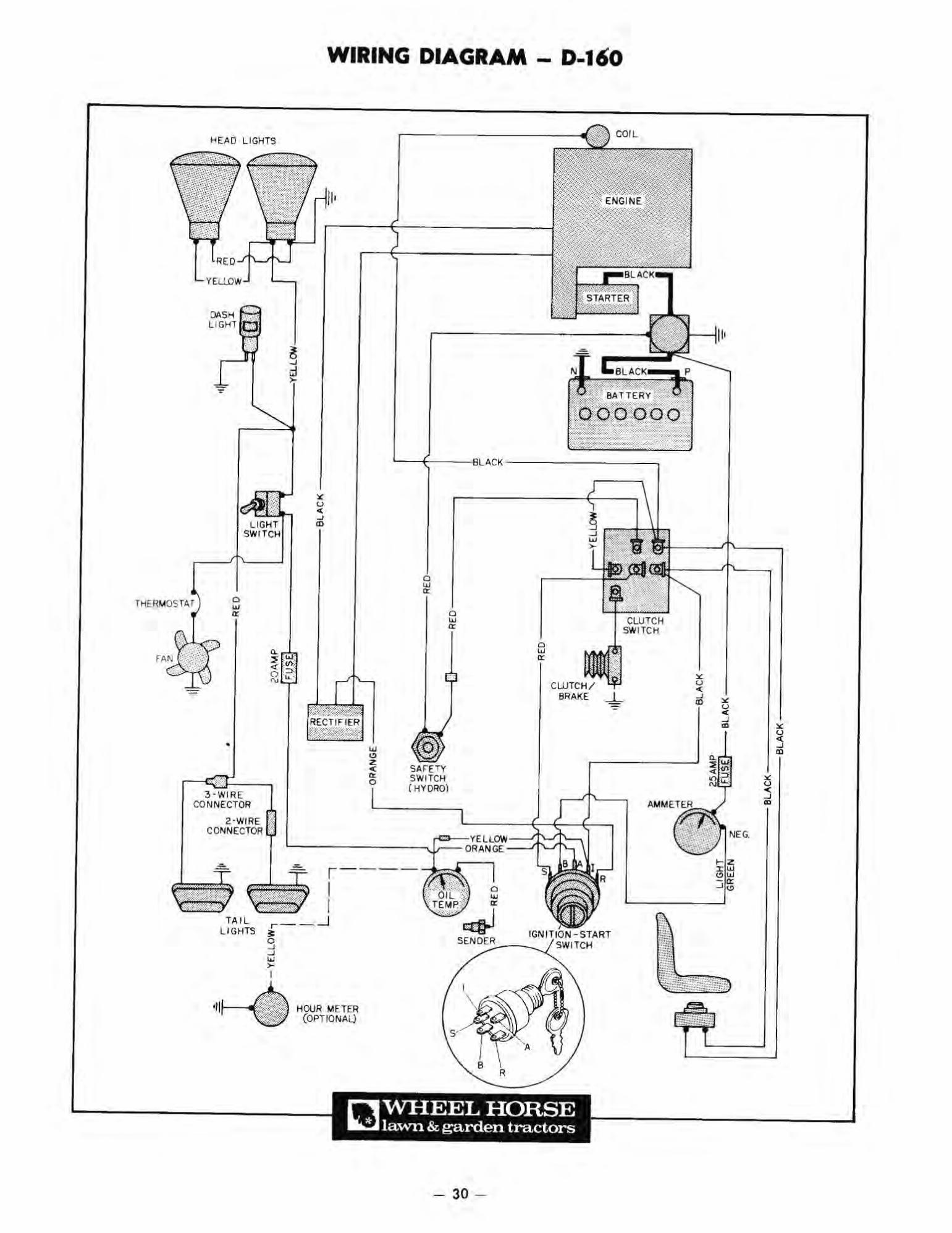
lHERMOS T~r
1" [ 11 0 LIGHTS
TAIL LIGHTS
WIRING DIAGRAM - 0·160
r - - I I
r-- --1
~ ~ > I
HOOR METER (OPTIO NAl)
- 30 -
CLUTCH SWI TCH
CLUTCH/ BRAKE ...L..

HEADLIGHTS
DASH LIGHT
THERMOSTAT
2-WIRE
TAI L LIGHTS
WIRING DIAGRAM - D-IOO
- -- -, I I
Q
~ I I
~ SENDER
nWHEEL HORSE III..!J lawn & garden tractors
- 31 -
REO
SEAT SWITCH
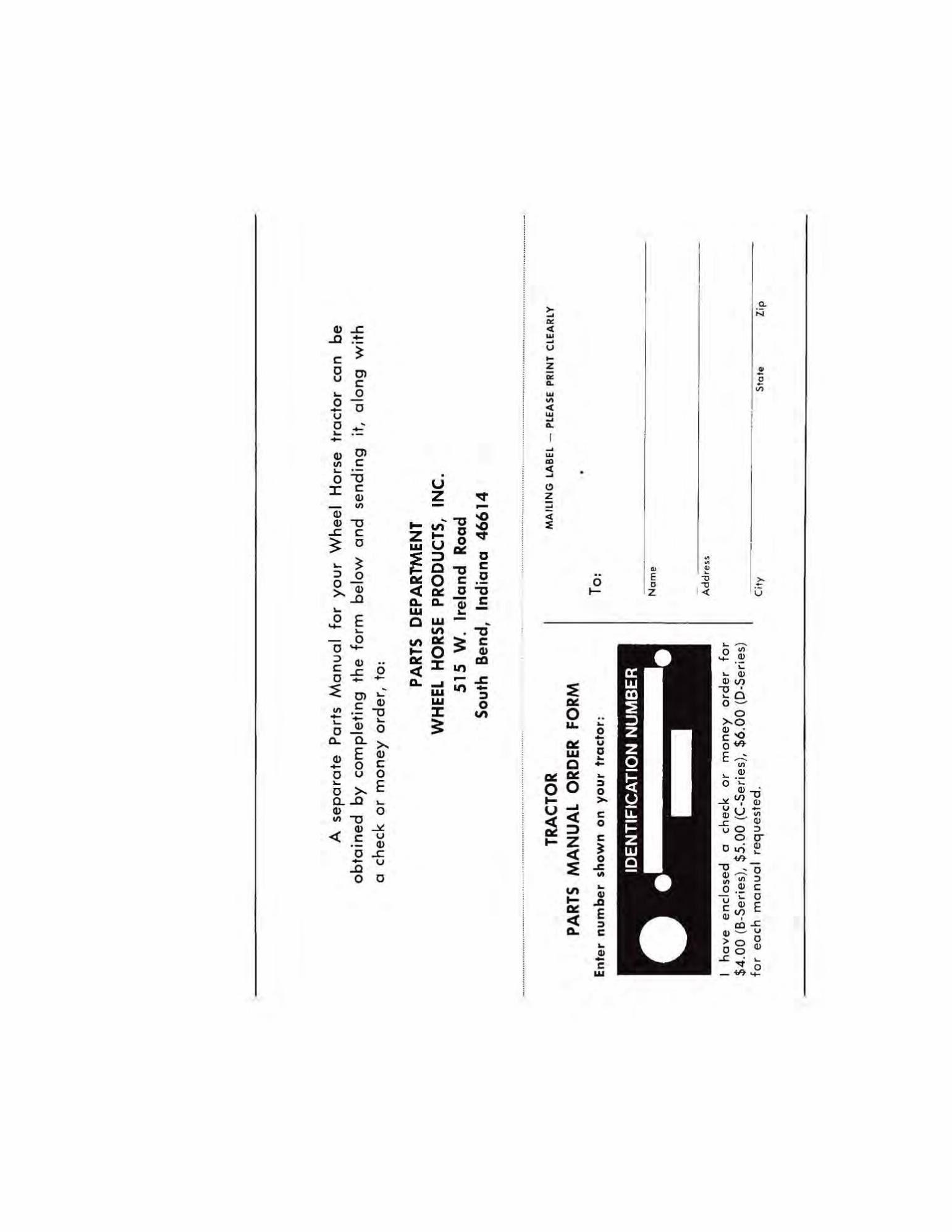
A
se
pa
rate
P
art
s M
an
ua
l fo
r yo
ur
Wh
ee
l H
ors
e
tra
cto
r ca
n
be
ob
toin
ed
by c
om
ple
tin
g t
he
form
b
elo
w o
nd
se
nd
ing
it,
al
on
g
wit
h
a ch
eck
o
r m
on
ey o
rde
r, t
o:
PAR
TS
DEP
AR
TMEN
T W
HEE
L H
OR
SE
PRO
DU
CTS
, IN
C.
51
5
W.
Irel
and
R
oad
Sou
th
Ben
d,
Ind
ian
a 4
66
14
-----
------
------
......
......
......
----
-----
-----
------
---...
......
......
......
...
------
-----
------
-----
.... __ .
_._ ....
TRA
CTO
R
PAR
TS
MA
NU
AL
OR
DER
FO
RM
En
ter
nu
mb
er
sh
ow
n o
n y
ou
r tr
acto
r:
I h
ov
e en
clo
sed
0
chec
k o
r m
on
ey
ord
er
for
$4
.00
(B
·Ser
;es)
, $5
.00
(C·S
edes
), $
6.0
0 (
D·S
edes
) fo
r e
ach
m
anu
al r
equ
este
d.
To:
No
me
Ad
dre
n
Cif
y
MA
rLIN
G L
AB
EL
-P
LEA
SE
P
RIN
T
CLE
AR
LY
•
Sto
te
Zip