l)PERA TION AND SERVICE MANUAL - Wheel Horse Parts ...
15
30 j,., ). /5../l-Vl· D:u{l J1:- /6 7'/ '- l)PERATION AND SERVICE MANUAL . .· .. ' - 1 fly-' H - ;o J?f!l' l!J 3 model 953 {;J (;; ;;z - 'b- <f J )/-710 110 5 !Jb !fiJ<"-4 - ./i)"6 fik. . (/ 4320 6 )( t; ,(" t:L A ctcA # ; s-<Js- SOUTH BEND. !JND.
-
Upload
khangminh22 -
Category
Documents
-
view
1 -
download
0
Transcript of l)PERA TION AND SERVICE MANUAL - Wheel Horse Parts ...
30 j,., ). ~ /5../l-Vl· :.c:.-~
D:u{l J1:- /6 7'/ '
l)PERA TION AND
SERVICE MANUAL
. .· .. '
-1 t~ fly-' H -;o
J?f!l' l!J 3 ~------
model 953
~ {;J (;; ;;z - 'b- ~ <f J
~ )/-710 ~ 110 5 !Jb
!fiJ<"-4 ~ - ./i)"6 fik. . (/ 4320 4/0()~f)J.?? -(.753
g~~ ~~ 6 6/J.i"~~ )( t; ,("
,?~ t:L II~ A ~--- ctcA # ; s-<Js-
SOUTH BEND. !JND.

\
INDEX
SERIAL NUMBERS
Page Number
Engine . . . . . . . . . . . . . . . . . . . . . . . . . . . . . . . . . . . . . . . 2 Hydraulic Unit . . . . . . . . . . . . . . . . . . . . . . . . . . . . . . . . 10 Tractor . . . . . . . . . . . . . . . . . . . . . . . . . . . . . . . . . . . . . . 4
LUBRICATION and MAINTENANCE Battery . . . . . . . . . . . . . . . . . . . . . . . . . . . . . . . . . . . . . . 2 Care of Tractor . . . . . . . . . . . . . . . . . . . . . . . . . . . . . . . . 4 Engine . . . . . . . . . . . . . . . . . . . . . . (See Engine Manual) Front Wheel Bearings . . . . . . . . . . . . . . . . . . . . . . . . . . 3 Head and Tail lights . . . . . . . . . . . . . . . . . . . . . . . . . . 4 Hydraulic Unit . . . . . . . . . . . . . • . . . . . . . . . . . . . . . 10 Steering Gear . . . . . . . . . . . . . . . . . . . . . . . . . . . . . . . . . 8 Tractor (Before you start diagram) . . . . . . . . . . . . . . . . 3 Transmission . . . . . . . . . . . . . . . . . . . . . . . . . . . . . . . . . . 12
OPERATION Hydraulic Unit .. .... .............. ... ..... .. ... 10 Instruments and Controls . . . . . . . . . . . . . . . . . . . . . . 4 Parking Brake . . . . . . . . . . . . . . . . . . . . . . . . . . . . . . . . 4 Starting Engine .................. . . , . . . . . . . . . 4 Tires .......... : . . . . . . . . . . . . . . . . . . . . . . . . . . . . . . 4
PARTS LIST Engine ................... . .. {See Engine Manual) Hydraulic Unit . . . . . . . . . . . . . . . . . . . . . . . . . . . . . . . . 11 Steering Gear . . . . . . . . . . . . . . . . . . . . . . . . . . . . . . . 9 Tractor ... ... , .. , .. , .. , . , ................. , . . 7 Transmission . . . . . . . . . . . . . . . . . . . . . . . . . • . . . . . . 12
PARTS DIAGRAMS Body and Seat Assembly . . . . . . . . . . . . . . . . . . . . . . . 5 Engine ....................... {See Engine Manual) Hydraulic Unit . . . . . . . . . . . . . . . . . . . . . . . . . . . . . . . . . 11 Main Frame Assembly . . . . . . . . . . . . . . . . . . . . . . . . . 6 Steering Gear . . . . . . . . . . . . . . . . . . . . . . . . . . . . . . . 9 Ste·ering and Wheel Assembly .... , . . . . . . . . . . . . . . 6 Transmission ................................ 12 Wiring Diagram . . . . . . . . . . . . . . . . . . . . . . . . . . . . . . . 5
SPECIFICATIONS ........... . ...... .. .. . . ..... , . 5
There is NO OIL in the crankcase of the engine when shipped from the factory. Read Engine Manual ond follow all instructions pertaining to type of lubrication specified. The engine is the heart of your tractor and it is very important that you keep it in good condition.
Page 2
.... I
~~{J:¥i[i!iM¥Q..I~J.Q!!M'\g!&l !..VJ:M@MMflm'M:M!\}41' ?J¥ ~ ,.. .
WARRANTY We warrant WHEEL HORSE PRODUCTS for
ONE YEAR from date of purchase against defective parts and workmanship. We will replace, free of charge, any defective part if returned to the factory PREPAID*. Wheel Horse Products, Inc., reserves the right to make changes or improvements upon its products without imposing ony obligations upon itself to install the same upon its products that have been previously manufactured.
The engine and battery carry a separate warranty by the manufacturer. FOR ENGINE OR BATTERY SERVICE, CONTACT YOUR LOCAL ENGINE OR BATTERY SERVICE HEADQUARTERS.~ I *All warranty claims, work, shipments, must be handled
through your authorized Wheel Horse dealer.
_, NOTE: 90 Day Warranty for Commercial Use. .
~~IITtiiTttmM'IM'l~~~
TRANSMISSION
Remove oil filler plug, located at the left rear side of the transmission, and fill to level of hole with a good grade of S.A.E. 90 Gear Lube (will require about 3 pints).
The transmission should be checked after every 40 hours of use. The transmission should be drained once a year by removing plug on bottom to drain oil. Refill as above paragraph. This is a regular automotive type transmission with sliding gears and should have the same care as your car.
BATTERY
With proper care this battery should give the long service life built into it.
A battery which does not function properly is not necessarily worn out or defective. It may only need a good recharge. Therefore, if battery trouble is suspected, a full recharge and test by a competent battery man is recommended.
Putting Battery In Service
Remove wicks or tape covering from vent hole in filler caps. Make sure vent holes are open so that gas produced when battery is charging can escape. If necessary, run a fine wire in vent hole to be sure it is open and free of all obstructions.
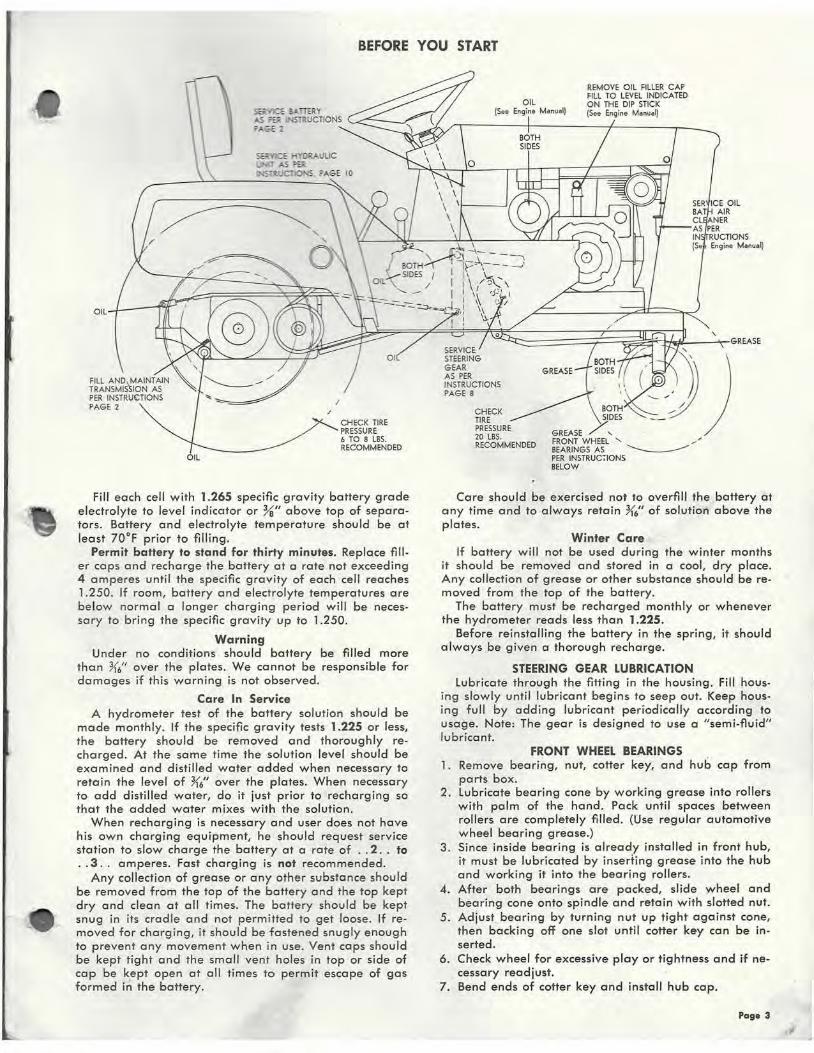
BEFORE YOU START
OIL
OIL
~·CE eATIERY ..S =91 NSTRUCTIONS '----"---~
""* 2
CHECK TIRE PRESSURE 6 TO 8 LBS. RECOMMENDED
Fill each cell with 1.265 specific gravity battery grade electrolyte to level indicator or %" above top of separators. Battery and electrolyte temperature should be at least 70oF prior to filling.
Permit battery to stand for thirty minutes. Replace filler caps and recharge the battery at a rate not exceeding 4 amperes until the specific gravity of each cell reaches 1.250. If room, battery and electrolyte temperatures are below normal a longer charging period will be necessary to bring the specific gravity up to 1.250.
Warning Under no conditions should battery be filled more
than K6" over the plates. We cannot be responsible for damages if this warning is not observed.
Care In Service A hydrometer test of the battery solution should be
made monthly. If the specific gravity tests 1.225 or less, the battery should be removed and thoroughly recharged. At the same time the solution level should be examined and distilled water added when necessary to retain the level of K6" over the plates. When necessary to add distilled water, do it just prior to recharging so that the added water mixes with the solution .
When recharging is necessary and user does not have his own charging equipment, he should request service station to slow charge the battery at a rate of .. 2 .. to .. 3 .. amperes. Fast charging is not recommended.
Any collection of grease or any other substance should be removed from the top of the battery and the top kept dry and clean at all times. The battery should be kept snug in its cradle and not permitted to get loose. If removed for charging, it should be fastened snugly enough to prevent any movement when in use. Vent caps should be kept tight and the small vent holes in top or side of cap be k,ept open at all times to permit escape of gas formed in the battery.
GREASE
REMOVE OIL FILLER CAP FILL TO LEVEL INDICATED ON THE DIP STICK (See Enqine Monu•Q
FRONT WHEEL ' , BEARINGS AS -....______..., PER INSTRUC710NS BELOW
Care should be exercised not to overfill the battery at any time and to always retain K/' of solution above the plates.
Winter Care If battery will not be used during the winter months
it should be removed and stored in a cool, dry place. Any collection of grease or other substance should be removed from the top of the battery.
The battery must be recharged monthly or whenever the hydrometer reads less than 1.225.
Before reinstalling the battery in the spring, it should always be given a thorough recharge.
STEERING GEAR LUBRICATION lubricate through the fitting in the housing. Fill hous
ing slowly until lubricant begins to seep out. Keep housing full by adding lubricant periodically according to usage. Note: The gear is designed to use a "semi-fluid" lubricant.
FRONT WHEEL BEARINGS 1. Remove bearing, nut, cotter key, and hub cap from
parts box. 2. lubricate bearing cone by working grease into rollers
with palm of the hand. Pack until spaces between rollers are completely filled. (Use regular automotive wheel bearing grease.)
3. Since inside bearing is already installed in front hub, it must be lubricated by inserting grease into the hub and working it into the bearing rollers.
4. After both bearings are packed, slide wheel and bearing cone onto spindle and retain with slotted nut.
5. Adjust bearing by turning nut up tight against cone, then backing off one slot until cotter key can be inserted.
6. Check wheel for excessive play or tightness and if necessary readjust.
7. Bend ends of cotter key and install hub cap.
Pa ge 3

INSTRUMENT PANEL & CONTROLS
STARTING ENGINE
( 1) Before starting engine open valve on sediment bowl. (See Figure II Page 9 for location)
(2) Place gear shift lever in neutral position. (3) Push throttle lever !1 way forward in slot. (4) Push choke lever all the way forward to choke en
gine. If engine is warm and has been running, choking will not be necessary.
(5) Turn key to on position and push starter button. 6} When engine starts, slowly pull choke lever back to
off position and adjust throttle to desired speed. 7 ) Depress clutch pedal on left side of tractor before
selecting desired gear range. 8) When starting tractor in winter it is desirable to de
press clutch so engine does not have to turn trans-mission.
CLUTCHING Don't force the gear shift lever if the gears do not im
mediately mesh. Depress clutch pedal all the way down and let up, then depress again and shift. To avoid sudden starts, release clutch pedal slowly. While in motion do not shift gears without depressing clutch pedal.
The clutch pedal also operates the brakes WHEN DEPRESSED All THE WAY DOWN. For this reason, you should depress the clutch pedal only YJ OF THE WAY DOWN WHEN SHIFTING while in motion. This clutchbrake pedal combination makes clutching automatic as you apply the brakes to stop.
PARKING BRAKE The parking brake is located on the left side of the
tractor. To set the parking brake, depress the clutch brake pedal as far as possible and pull the parking broke lever toward the rear. To release the broke depress the clutchbroke pedal, parking brake will automatically release.
ATTACHING TOOLS Complete information on the assembly, attachment,
operation and service C?f the many attaching tools will be provided with each attachment.
Page 4
OIL BATH AIR CLEANER Remove cleaner cover and add oil until the level reaches
the arrow marked on the air cleaner bowl.
TIRES The front tires are 4:00 x 8 and should be inflated to 20
lbs. of air pressure. The rear tires are 6:40 x 15 and should hove 6 to 8 lbs. of air pressure. The tires con also be filled with ballast if desired. Ordinarily this is not necessary as the weight of the operator will add sufficient weight for adequate traction.
HEAD AND TAIL LAMPS The tractor is equipped with two headlamps and a tail
lamp. The off-on switch is located on the left rear corner of the dash panel. To replace burned out headlamp bulbs, remove the three (3) screws on back side of lamp mounting bracket, remove lamp housing, replace the bulb and re-install housing. Tail lamp bu lb is replaced by pulling bulb housing rearward from lens a nd replacing burned out bulb. Reassembly by pressing housing into lens as far as it w ill go.
CARE OF THE TRACTOR (1) Keep tractor greased and oiled regularly. See previous
instructions for location of grease fittings. Check transmission and engine case oil levels.
{2) Keep engine air filter clean. Dirty filters use excessive fuel and reduce engine power and life.
{3) Keep tires properly inflated. (4) Keep tractor covered and in a dry place when not in
use. {5) Keep gross and dirt out of engine cowling as they will
stop the flow of cooling air and cause serious overheating.
{6) BRAKE ADJUSTMENT: The brake bond, located on the left side of the transmission, brakes the transmission and in turn stops the wheels. Adjust the nut on the brake rod so that, when you depress the clutch pedal all the way down, the band tightens around the brake drum just as the idler pulley releases the belt. Keep broke bond and drum free from oil and dirt.
{7) CLUTCH-BRAKE PEDAL ADJUSTMENT: The pedal rod may be moved in or out to adjust pedal to desired position. Remove pin from rod and remove rod from peda l lug, adjust rod and replace.
(8) PARKING BRAKE ADJUSTMENT: After brake bond and clutch-broke pedal have been adjusted, depress pedal until tractor brakes are locked. Pull parking broke lever back and adjust nut on bottom of lever shaft until lever will engage and hold pedal down.
(9) HYDRAULIC BELT ADJUSTMENT: Proper belt tension is maintained by removing the right hand belt guard and loosening the four {4) bolts holding the pump body to the frame. Pump may now be moved forward and backward to adjust belt.
( 1 0) When replacing belts it is advisable to purchase them from your Wheel Horse dealer, as these belts are specifically designed for each tractor or attachment. A new drive belt may have a tendency to squeak during clutching, this will stop after an hour or two of operation as the belt seats in the pulley groove. When replacing bolts or mounting drive implements make sure all pulleys ore in line.
(11) Check battery liquid after every 40 hours of use. If tractor has been in storage it may be necessary to re· charge.
{12) Your tractor is only as good as the service you give it. See your Wheel Horse dealer for a thorough check-up after each season of use.
-

Tractor (Hood Removed)
953 SPECIFICATIONS (Specifications subject to change without notice.}
Length Overall ........................................ 69 inches Wheelbase . . . . . . . . . . . . . . . . . . . . . . . . . . . . . . . . . . . . . . . . . . . . 47 inches Width Overall . . . . . . . . . . . . . . . . . . . . . . . . . . . . . . . . . . . . . . 36).-S inches Width ot Front Wheels . . . . . . . . . . . . . . . . . . . . . . . . . . . . . . . . . 33 inches Height . . . . . . . . . . . . . . . . . . . . . . . . . . • . . . . . . . . . . . . . . . . . . . . 42 inches Height to Top of Hood ................................ 35 inches Net Weight ............ . ...............................
1656 ,lbs.
Crop Clearance . . . . . . . . . . . . . . . . . . . . . . . . . . . . . . . . . . . . . . . 9).-S inches Frome Clearance . . . . . . . . . . . . . . . . . . . . . . . . . . . . . . . . . . . . . 13X inches Engine (4-cycle, sing le cy li nder, oir cooled) .................. 9.6 H.P. Fuel Copocity ........................................ 2% gallons Tires (front) ................. 4:00 x 8" Pneumatic (16" wheel dio.} Tires (reor} . . . . . . . . . . . . . . . . . 6:40 x 15" Pneumatic (27" wheel dio.}
@~ ~
TAIL lLtiP
Body & Seat Ass'y.
KOHl..ER p,e HP ...
953 Wiring Diagram
OO<IUNO
Page S o~>

Main Frame Ass'y.
Steering & Wheel Assiy. Page 6

953 TRACTOR PARTS LIST (See Page 12 for Transmission Parts List, Page 9 for Steering Gear Parts List and Page 11 for Hydraulic Unit Parts List)
When ordering parts a lways lis! Por~ No. a nd name of pa rt. ~R~e~f-. -r--~Pa-rt--~~----------------------------r-7N~o--.
No. No. Description Req'd.
l Ref. Part No. No. No. Description Req'd.
1 2840 Au'y. f rame l 2 2773 Axle - Front 1 3 1030 Fitting • Grease 4 4 2736 Ass 'y. Pin & Plate • Axle Mt'g. 1 5 908032-4 Bolt • Hex. % -16 x ~~ 2 6 920083-4 lock washer % Dio. 8 7 2733 Arm • Steering R.H. 1 8 2732 Arm - Steeri ng l,H. 1 9 933230 Roll Pin K6 x H-s 2
10 3364 Au'y. Spindle ltH. 1 11 3365 Au'y. Spindle l.H. 1 12 2710 Au'y. Ball Joint 1 13 2771 Rod • Drag Link 1 14 2711 Au'y. Tie · Rod 1 15 915002-6 Nut · Hex. - Nyloc~ % -24 4 16 915004-6 Nut - Hex. · Nylock 72-20 1 17 2777 Pedal - Clutch 1 18 S-50-75 Snap Ring - T ruorc 7,1 Shaft 5 19 3017 Shaft 1
83 908001-4 Bolt • Hex. )1. -20 x X 2 84 920081-4 lockwa.sher )1. Dio. 17 as 908003-4 Bolt • Hex. )1. -20 X % 10 86 2775 Au'y. lomp . Toil light 1 87 2580 Ass'y. Head light & Brkt. R.H. 1 88 2581 Au'y . Head light & Brkt. L.H. 1 89 2798 Housing - Control Panel 1 90 2870 Panel · Control 1 91 2871 Decal · Pan&l 1 92 2874 Bolt • Rd. Hd. # 10-24 x }ii 4 93 2774 Au'y. Lamp - G~>n. Wa rning 1 94 17 47 Ass'y. Switch Ignition 1 95 1751 Ass'y, Switch • Starter 1 96 2846 Bol t • Rd. Hd. )1. -20 x % 2 97 2784 Au 'y. lever Control R.H. Throttle 1 98 2785 Ass'y. lever Con trol L.H. Throttle I 99 'J797 Leve r & Knob Au'y. 2
100 3329 Screw · Specia l 2 10 1 915000-6 Nut Hex. Nylock Y.-28 2
20 2891 Arm 1 21 3979 Arm - Clutch Rod Pi"ot I
102 4190 Bracket · Control R.H. 1 103 3330 Washer 4
22 933156 Roll Pin Ys x 1 Y:; 2 23 2731 Washer 1 24 1623 Pu lley - Jdle.r 1 25 1536 Bushing 1 26 908035-6 Bolt • Hex.. % -16 x 1Y:; Nylock 7 27 915113-6 Nul · Hex.- Nylock %·1 6 20 28 2741 Rod • Clutch 1
29 1861 Stud - Clutch Rod 1 30 S-52-3 Hair Pin Clip 2 31 1129 Spring · Cl111ch 1 3 2 2291 Brocket . Idler Belt Thro w · Out 1
104 3798 Coble - Ass'y. Cont rol • Throttle 1 105 4191 Bracket - Control L.H. 1 106 4034 Coble Au'y. Control • Choke 1 107 'J023 Retainer - Coble 2 108 1770 Engine 9.6 H.P. Kohler 1 109 3939 Elbow 1" -45 • . Exhaust 1 110 3947 Nipple 1 '1 Close · Exhaust 2 111 2873 Muffier 1 112 2720 Pulley . Engine 1 11 3 1349 K~y • Straight )1.; x )1.; x 1)11 1 114 909862-4 Set Screw K6·18 x K6 2
33 2830 Ass'y. lever · Parking Bra~e 1 34 2835 Spring · Torsion 1 35 1001 Knob 1
115 2834 Guard · Engine 1 116 2833 Spacer 3 11 7 909060-4 Bolt )i -20 x 1 Yz Rd. Hd. 5
36 2758 An'y. lift · Hydraulic 1 37 2754 Block • lift Pivot 2
118 1 787 Fitting ~-27 Straight · Nylon 1 119 1786 Au'y. Fuel Strainer I
38 908033-4 Soli • Hex. • % -16 x Ys 8 39 2744 Foot Rest R.H. 1
120 943289-4 Nipple · Fuel Strainer 1 121 2739 Hose • Fuel Line 1
40 2745 foot Rest LH. 1 122 4256 Clip 2 41 2796 Pad - Rest R.H. 1 123 1217 Fitting • Elbow • Fuel Pump 1 42 2799 Pod · Re•t LH. 1 43 909083-4 Bolt • Rd. Hd. %·16 x Ys 4
44 2713 Ass'y. Steering (Soe page 9 for Breakdown) 1
45 933192 Roll Pin ~6 >< 1Y, 2 46 2708 Grommet 1 47 2817 Steering Wheel 1 48 915235-4 Nut . Hex. - Jam Ya -18 1 49 2847 Insert · Steering Whoel 1 50 2718 Fuel Tonk I 51 2728 Block- Wood 2 52 2717 Sirop 2 53 3698 Speed Nut 4 54 926317-4 Screw · # 14 x% Rd. Hd. Self Topping 6 55 2714 Cop - Tonk 1 56 3926 Hitch 1 57 3988 Pin 1 58 2814 Ass'y. Cable & Yoke 1 59 932121-4 Pin · Clevis ~6 Die. 2 60 932001-4 Cotter Pin ){6 x % 2 6 1 3665 Clip ·Coble 1
62 2719 Ass'y. P11mp • Hydraulic (See poge 11 for Breakdown) 1
63 4812
'""~ ~ 1
64 909861 Set Screw K6· 18 x Y:; 2 65 908015-4 Salt - Hex. K6·18 x X 4 66 920082-4 lockwosher K6 Dio. 4 67 92000S-4 Washer - Plain K6 8 68 2721 Ass'y. Cylinder . Hydraulic 1 69 2747 Pin · Pivot 1
124 2815 Housing . Grille 1 12-5 3764 " U" Bolt 2 126 2810 Grille 1 127 3699 Speed Nul 2 128 3368 Ass'y. Wheel Tire & Tube - Front 2 129 3369 An' y. Wheul & Bearing 2 130 3370 Cone & Bearing 4 131 3371 Cup • Bearing 4 132 3373 Seal - Bearing 2 133 1656 Tire 2 134 1657 lube 2 135 3372 Hubcap 2 136 915035-4 NYt • Castle ~-16 2 137 932019-4 Cotter Pin Ya >< 1X 2 138 2845 Ass'y. Wheel & l'ire - Rear 2 139 2715 Wheel 2 140 2722 - Tire 2 141 2723 Tube 2 142 2792 Ass'y. Cover - Shift Stick 1 143 1385 .Bolt . Hex. · Sems Y:;-20 x X 11 144 2795 Au' y. Guard R.H. 1 145 2783 Guard 1 146 2727 Frome • Seat 1 147 908021 -4 1 Bolt • Hex. Hd. X'6·18 x 1)/z 4 148 915112-6 Nut· Hex. Nylocll K6-18 4 149 2818 Plug • Square B11lton 2 150 2787 Cushion · Seat 1 151 2788 Cushion Book 1 152 2841 Cover · Hood 1 153 1345 Thumb Screw 4 154 J813 Pio - Tool 1
70 932124-4 Pin • Clevis X Dio. 1 71 932017-4 Cotter Pin }~ x ,X 1
155 1591 Belt 47'' Hyd. 1 156 1592 Bel t 82" Drive 1
72 4834 Streel Elbow Y:; NPTF 2 73 2729 Ass'y. Hose · Hydro111ic 2 74 908002-4 Bolt · Hex. )1. -20 x % 2
157 1593 Belt Engine to Gen. 1 158 2829 Decal • ''953" 2 159 4410 Deca l - Wheel Horse Emblem 1
15 9 15 111·6 N11t · Nylock Y:;-20 10 160 2843 Decal - Steering Wheel Insert 1
76 2712 Battery 1 77 2725 Angle - Battery Clomp 1 7S 2724 Hook - Battery 2 79 2848 Ass'y. Wiring Harness 1 ro 4432 W ire • Ground 1
161 4418 Decal · Shift & Serial Number 1 162 4058 Wire Au'y. 2 163 4045 Bracket • Head Light 2 164 2895 Gasket • Head light 2 165 4801 lens & Ho11sing Ass'y. 2
31 4802 Switch - Push · Pu ll 1 166 2894 Bulb · Head Light 2 az ' 2836 Bracket · Headlight 1 167 926359-4 Screw 6
Page 7
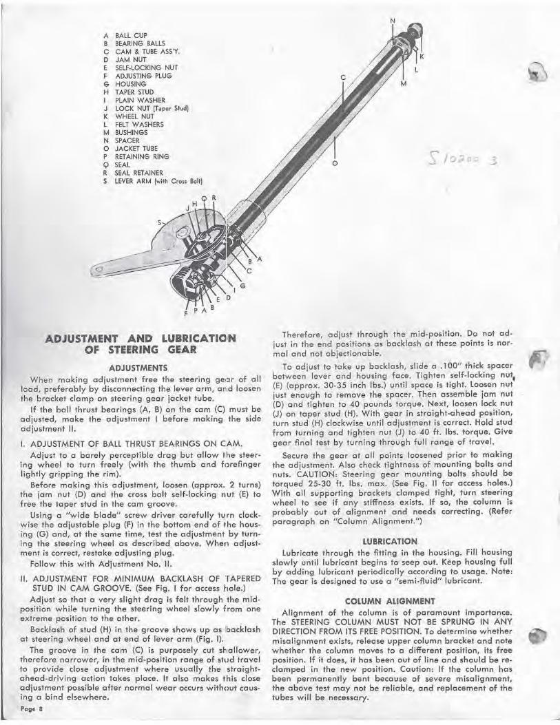
A BALL CUP B BEARING BALLS C CAM & TUBE ASS'Y, D JAM NUT E SELF-LOCKING NUT F ADJUSTING PLUG G HOUSING H TAPER STUD I PLAIN WASHER J LOCK NUT (Taper Stud) K WHEEL NUT L FELT WASHERS M BUSHINGS N SPACER 0 JACKET TUBE P RETAINING RING Q SEAL R SEAL RETAINER S LEVER ARM (with Cross Bolt)
ADJUSTMENT AND LUBRICATICIN OF STEERING GEAR
ADJUSTMENTS When making adjustment free the steering geoor of all
load, preferably by disconnecting the lever arm, al'ltd loosen the bracket clamp on steering gear jacket tube.
If the ball thrust bearings (A, B) on the cam (C) must be adjusted, make the adjustment I before making the side adjustment II.
I. ADJUSTMENT OF BALL THRUST BEARINGS ON CAM. Adjust to a barely perceptible· drag but allow the steer
ing wheel to turn freely (with the thumb and fc>refinger lightly gripping the rim).
Before making this adjustment, loosen (approx. 2 turns) the jam nut (D) and the cross bolt self-locking nut (E) to free the toper stud in the cam groove.
Using a ''wide blade'' screw driver carefully turn clockw ise the adjustable plug (F) in the bottom end of the housing (G) and, at the same time, test the adjustment by t\lrning the steering wheel as described above. When adjustment is correct, restake adjusting plug.
Follow this with Adjustment No. II.
II. ADJUSTMENT FOR .MINIMUM BACKlASH OF TAPERED STUD IN CAM GROOVE. (See Fig. I for access hole.)
Adjust so that a very slight drag is felt through the midposition while turning the steering wheel slowly from one extreme position to the other.
Backlash of stud (H) in the groove shows up as !backlash at steering wheel and at end of fever arm (Fig. 1).
The groove in the cam (C) is purposely cut shtallower, therefore narrower, in the mid-position range of stud travel to provide close adjustment where usually the straightahead-driving action tokes place. It also makes this close adjustment possible after normal wear occurs with(Jut cous~ ing o bind elsewhere. Page 8
Therefore, adjust through the mid-position. Do not adjust in the end positions as backlash at these points is normal and not objectionable.
To adjust to toke up backlash, slide o .1 00" thick spacer between lever and housing face. Tighten self-locking nut, (E) (opprox. 30-35 inch lbs.) until space is tight. loosen nut just enough to remove the spacer. Then assemble jam nut (D) and tighten to 40 pounds torque. Next, loosen lock nut (J) on toper stud (H). With gear in straight-ahead position, turn stud (H) clockwise until adjustment is correct. Hold stud from turning and tighten nut (J) to 40 ft. lbs. torque. Give gear final test by turning through full range of travel.
Secure the gear at all points loosened prior to making the adjustment. Also check tightness of mounting bolts and nuts. CAUTION: Steering gear mounting bolts should be torqued 25-30 ft. lbs. max. (See Fig. II for access holes.) With all supporting brackets clamped fight, turn steering wheel to see if any stiffness exists. If so, the column is probably out of alignment and needs correcting. (Refer paragraph on "Column Alignment.")
LUBRICATION lubricate through the fitting in the housing. Fill housing
slowly until lubricant begins to seep out. Keep housing full by adding lubricant periodically according to usage. Note: The gear is designed to use a "semi-fluid11 lubricant.
COLUMN ALIGNMENT Alignment of the column is of paramount importance.
The STEERING COLUMN MUST NOT BE SPRUNG IN ANY DIRECTION FROM ITS FREE POSITION. To determine whether misalignment exists, release upper column bracket and note whether the column moves to o different position, its free position. If it does, it has been out of line and should be reclamped in the new position. Caution: If the column has been permanently bent because of severe misalignment, the above test may not be reliable, and replacement of the tvbes will be necessary.

1
953 STEERING GEAR PARTS LIST When ordering ports always list Pa rt No. and nome of part.
Ref. Part No. Ref. Part No. No. No. Description Req'd. No. No. Description Req'd.
I 3780 lever Arm (with cross bolt) I 10 9 15117·6 Self . locking Nut %·11 Hex. 1 2 915087·4 lock Nut (taper stud) ).1·20 Hex. 1 11 915240·4 Jam Nut %·11 Hex. 1 3 378 1 Topor Stud I
4 3782 Seal 1 5 3783 Seal Retainer 1
12 3789 Plain Washer 1
13 3791 Com & Tube Ass'y. 1
6 3784 Adjusting Plug 1 14 3793 Spacer 1
7 3785 Retaining Ring 2 IS 3788 ~ Housing & Jacket Ass'y. 1
8 3786 Boll Cup 2 16 3794 Bushing I
9 3787 Bearing Bolls 20 ~ 17 3795 Felt Washers 2
FIGURE I FIGURE II Page 9
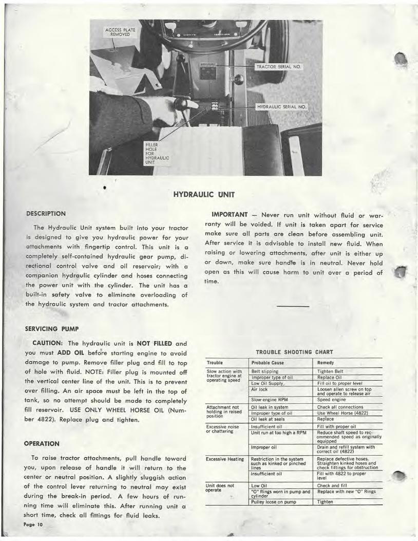
• HYDRAULIC tJNIT
DESCRIPTION
The Hydraulic Unit system built into your tractor
is designed to give you hydraulic power for your
attachments with fingertip control. This unit is a
completely self-contained hydraulic gear pump, di
rectional control valve and oil reservoir; with a
companion hydraulic cylinder and hoses connecting
the power unit with the cylinder. The unit has a
built-in safety valve to eliminate overloading of
the hydraulic system and tractor attachments.
SERVICING PUMP
CAUTION: The hydrau lic unit is NOT FILLED and
you must ADD OIL befJre starting engine to avoid
damage to pump. Remove filler plug and fill to top
of hole with fluid. NOTE: Filler plug is mounted off
the vertical center line of the unit. This is to prevent
over filling. An air space must be left in the top of
tank, so no attempt should be made to completely
fill reservoir. USE ONLY WHEEL HORSE OIL (Num
ber 4822). Replace plug and tighten.
OPERATION
To raise tractor attachments, pull handle toward
you, upon release of handle it will return to the
center or neutral position. A slightly sluggish action
of the control lever returning to neutral may exist
during the break-in period. A few hours of run
ning time will eliminate this. After runn ing unit a
short time, check all fittings for fluid leaks.
Page 10
IMPORTANT - Never run unit without fluid or war
ranty will be voided. If unit is taken apart for service
make sure all parts are clean before assembling unit.
After service it is advisable to install new fluid. When
raising or lowering attachments, after unit is either up
or down, make sure hand1e is in neutral. Never hold
open as this will cause harm to unit over a period of
time.
TROUBLE SHOOTING CHART
Trouble Probable Cause Remedy '
Slow action with Belt slipping Tighten Belt tractor engine at Improper type of oil Replace Oil operating speed
Low Oil Supply, Fill oil to proper level Air lock Loosen allen screw on top
and operate to release air Slow engine RPM Speed engine
Attachment not Oil leak in system Check all connections holding in raised Improper type of oil Use Wheel Horse (4822) position
Oi l leak at seals Replace
Excessive noise Insufficient oil Fill with proper oil or chattering Unit run at too high a RPM Reduce shaft speed to rec-
ommended speed as originally equipped
Improper oil Ora in and refi II srstem with correct oil (4822
Excessive Heating Restriction in the system Replace defective hoses. such as kinked or pinched Straighten kinked hoses and lines check fittings for obstruction Insufficient oil Fill with 4822 to proper
level
Unit does not Low Oil Check and f ill operate "0" Rings worn in pump and Replace with new "0" Rings . cylinder
Pulley loose on pump Tighten

u . f
•
I
953 HYDRAULIC UNIT PARTS LIST When ordering parts always list Part No. and name of part.
- ,,
Ref. Part No. Ref. Part No. No. No. Description Req'd. No. No. Description Req 'd.
1 4152 Body 21 1451 Cover Screw #10-32 x K6 6
2 4831 U6 Relief Ball 22 920120-4 lockwasher # 10 Ext. Tooth 6 3 4832 Spring 23 4841 Drive Shaft Assembly 1 4 4833 Plug 24 4839 Id ler Gear 1 5 1447 Shaft Seal 25 4840 Idler Shaft 1 6 909084-4 Screw %·16 x ~ 7 920083-4 lockwasher Ya 8 1001 Knob
9 4153 Handle 1
10 908817·4 Screw ~-20 x Ya 2
11 920081-4 lockwasher ~ Dia. 2
12 1449 Spirolox Snap Ring
13 943459-4 Allen Hd. Pipe Plug
14 915236·4 Hex. Jam Nut %·16
26 4842 Gasket 1
27 908203-4 !.1·20 X !.1 Hex. Bolt 1
28 4188 Washer 1
29 4157 Reservoir 1
30 4187 Stud 1
31 1453 Washer 1
32 4165 Head 1
33 145()- "0'' Ring 3
15 1455 "0" Ring 3 1457 Back-Up Washer 2
16 4154 Spool Valve 35 4846 Tube 1
17 933169 Roll Pin ~2 x W6 36 4156 Clevis 1
18 4837 Return Spring 37 1456 "0" Ring 1
19 933158 Roll Pin Ys x 1~ 38 4848 Guide 1 20 4838 Cover 39 4849 Piston Rod Assembly 1
Page 11

l
F' , v
0
'
••
953 TRANSMISSION PARTS LIST When ordering parts a lwa ys list Port No. and name of part . . .
Ref. Part No. Ref. Part No. No. No. Description Req'd . No. No. Description Req'd.
1 4160 Case · Transmission R.H. 1 40 2827 Shaft • Differential 1 2 1533 Bearing . Boll 2 3 3915 Pin . locating 2
41 908044·4 Cap Screw • Hex. % -16 x 4 4 42 1022 Nut • Hex. Hug • lock %-16 4
4 1532 Soaring . Need le 1 43 2824 Axle · Rear R.H. 1 5 1529 Bearing • Need le 2 44 2825 Axle · Rear l.H. 1 6 1508 Bearing . Needle 2 45 3912 Gasket 1 7 1526 Soaring • Needle 1
I 8 ~21y Seal • Oil tYa I.D. 2 9 1303 Seal • Oil % I.D. 1
10 3503 Fork . Shift 2 11 3515 Rail • Front Shift 1 12 3516 Rail · Rear Shift 1 13. 933156 Pin · Roll Ya x 1 2 14 3517 Ball · Stop 2 15 3518 Spring • Stop 1
46 2826 Block . Differential 2 47 4161 Case · Transmission l.H. 1 48 1530 Bearing · Need le 1 49 1531 Bearing · Needle 1 50 943460-4 Plug • X Pipe 1 51 2828 Washer • Thrust 2 52 943420-4 Plug % Pipe Sq. Hd. 1 53 908038-4 Screw • Hex. Cap % ·16 x 2 5 54 908043·4 Screw • Hex. Cap % -16 x 3X 1
16 3573 Shift Pin • Stop 1 55 91511 3'-6 Nut • Nylock % ·16 9 17 3522 Gear • Input Drive 1 18 1518 Bearing . Needle · 1
: 19 3907 Shaft . Spline 1
56 2726 Stick . Shift 1 57 3514 Collar · Shift 1 58 933168 Pin • Roll jfz x 1)(6 1
20 S-50-75 Snapring Truorc % Shaft 1 59 909854-4 Screw • Soc. Hd. Set X -20 x % 1 21 3523 Gear (Hi & inter) 1 60 915111 -6 Nut • Hex. lock X ·20 Nylock 1 22 3524 Gear (low & Reverse) 1 61 3577 Boot · Shift lever 1 23 3526 Gear • Spline Shaft 1 62 2709 Knob • Shift < 1 24 3910 Cluster • Shaft 1 25 937014 Key /f9 Woodruff 3 26 3525 Gear · Cluster 1
63 3902 Drum · Broke ~{r 1 64 937022 Key # 15 Woodruff 1 65 S-50· 100 Snap Ring 1" Shaft 1
27 1504 Bushing • Bronze 2 28 '3528 Pin ion . Cluster Shaft Reduction . 1 29 3527 Goar • Cluster Shaft Reduction 1
66 4437 Band • Brake 1 67 908002-4 Screw • Hex. Cap C.P. X ·20 x Ya 2 68 920081 ·4 Washer • C.P. X 2
30 4294 Gear • Revene Idler 1 31 1516 Bushing • Bronze ' ·1 32 3909 Pin • Reverse Idler 1
69 2707 Pulley 1 70 909862·4 Set Screw X6· 18 x X, 2 71 908035·4 Bolt • Jiex. % -16 x 1X 4
33 4166 Gear • Broke Shaft 1 72 920083-4 lockwasher % Dia. 4 34 2821 Gear • Ring 1 35 2822 Case • Differential R.H. 1 36 2823 Case · Differential l.H. 1
73 1488 Hub · Rear Wheel 2 74 909554-4 Set Screw · Sq. Hd. %-16 x 1 2 75 1349 Key • Straight X x X x 1X 2
37 2820 Gear . Axle 2 76 3935 Rod · Brake 1 38 933217 Pin • Roll X x 1 X 2 77 1487 lug Soh • Wheel Hub 8 39 2819 Gear • Differential Pinion 2 78 S-52·3 Hair Pin 1
12 11-29-62 1
FORM NO. 123

.. PRODUCTS, INC.
\
Stop - Rear
1/32 to 1/16 Fig. 1
SUPPLEMENT SHEET # 1
9 53 Tractor Manual Revisions
I. FIG. 1 - A Belt Guide, Port No. 4195 added. It attaches to the Frome and to the side of Engine
and runs along bottom side of Drive Belt. It attaches to the Frame with a Bolt (%-16 x 1) Port No.
908034-4 and Nut (%-16) Nylock, Part No. 915113-6 and to the Engine with a Bolt (J{6-14 x 1) Part No. ~
908046-4 and Lock Washer J{6 Dia., Part No. 920084-4. The Guide is to be tightened to Tractor only when
it is placed along bottom of Belt with ~2" to K6" clearance.
II. FIG. 1 - A Belt Stop (Rear), Part No. 4486 fits inside the Right Rear Fender with a Bolt <%-16 x %) Port No. 908032-4 and lock Washer % Dia., Part No. 920156-4 and extends down to top of Drive Belt
on Transmission Pulley. The Belt Stop is to be tightened only when it is ~2" to K6" away from top of Belt.
Ill. FIG. 1 - A Belt Stop (Front), Part No. 4796 fits on Engine with a bolt 908046-4 (J{6-l4 x 1) and Plain
Washer 920010-4 and Lock Washer 920084-4. It extends down to Belt on Engine Pulley. It is to be tightened
only when it is ~2" away from top of Belt.
1-15-63 FORM NO. 123-A

Clutch Range
Parking Brake Lever
Clutch Rod
Brake Range Adjusting Nut
Fig. 2 Brake Rod Nut
IV. IMPORTANT: ADJUSTMENT OF CLUTCH BRAKE PEDAL. ADJUST AS FOLLOWS:
PAGE NO.
6 6 6
PAGE NO.
6 6 6
12 • 12
l. Adjust Pedal to X" to 1" position by adjusting Clutch Rod.
2. Depress Pedal to approximately the 3" dimension and swing
Parking Brake lever until it holds Pedal at the 3" position.
3. Tighten Brake Rod Nut until Brakes lock.
4. This procedure must be followed after l 0-15 hours of operation
on initial run-in of Tractor. This adjustment should be repeated if
the Clutch Pedal approaches the top of the slot in the Belt Shield.
Failure to adjust may result in failure of the main Drive Belt.
PARTS LIST CHANGES
ILLUSTRATION REF. NO. OLD NO.
Steering and Wheel Assembly 21 3979 Steering and Wheel Assembly 22 933158 Main Frame Assembly 144 2795
NEW NO.
4199 933190 0{6 X 1}i)
2782
ILLUSTRATION REF. NO. LOOSE PARTS ADDED
Body and Seat Assembly 86 2884 (Nut Hex. 1"-27 Thin) Body and Seat Assembly 86 2885 (lock Washe r 1" Dia. Thin) Body and Seat Assembly 86 2883 (Lamp Bu lb) Transmission Parts list 69 909543 (Set Screw K6-18 x Ys) Transmission Parts list 69 915235-4 CKs-18 Jam Nut)

.,
PRODUCTS, INC.
Due to the great demand for 953 tractors, the steering unit previously obtained from a supplier is
being manufactured by Wheel Horse. To meet the increased production rote, the new ports shown below
hove been substituted for similar ports shown on page 6 in the 953 tractor manual.
t~ )~~;L4.. SUPPLEMENT SHEET #2.
9 53 Tractor Steering Revision }-.~
'·"' Ref. Part ' No. No. No. Description
. Req'd.
1 4876 Ass'y. Frame 1 2 4891 Rod - Drag Link 1 3 4877 Ass'y. lift - Hydraulic 1 4 4883 Ass'y. Shaft - Sector 1 5 908001-4 Bolt - Hex Y.l-20 x X 1 6 920007-4 Washer Y.; Dia. SAE. 1 7 920081·4 Lockwasher Y.; Dia. 1 8 4885 Ass'y. Shaft and Pinion 1 9 4880 Sector Steering 1
10 1030 Fitting - Grease 1 11 S-57-62 Washer - Shim 2 12 4875 Wheel - Steering 1 13 2897 Insert 1 14 937014 Key #9 Woodruff 1 15 5209 Washer-Shim 1 16 4890 Bushing - Steering Column 2 17 908031-6 Bolt Hex - Nylock %-16 x % 1 18 2844 Washer 1
5-10-63 FORM No. 123-B