L-l07, L-157 - Wheel Horse
12
OPERATIO A D S V E MA A WI H PART LIS WHEEL-HORSE PRODUCTS, INC. OWNERS MANUAL models · L-l07, L-157 • • i Riding Rotary Mower • • • • • • • • SOUTH BEND, IND.
-
Upload
khangminh22 -
Category
Documents
-
view
0 -
download
0
Transcript of L-l07, L-157 - Wheel Horse

OPERATIO A D
S V E MA A
WI H PART LIS
WHEEL-HORSE PRODUCTS, INC.
OWNERS MANUAL
models
· L-l07, L-157 • •
i Riding Rotary Mower • • • • •
• • •
SOUTH BEND, IND.

ASSEMBLY
A. The entire tractor unit is packaged in one carton and
the mower in a se parate carton.
B. OPEN TRACTOR UNIT FIRST. Remove all parts from
cart on and place in a convenient arrangement on a clean, level surface.
C. Slide the front wheels on to the spind les, and secure
with a washer Part No. 2844 and %-16 x Ys Nylok Bolt, Part No. 908033-6. Slide hub cap, Part No. 2816 over
hub.
D. The rear wheel is placed on the rear axle hub, Part No. 6400, and secured with three, % special bolts, Part No. 6401.
E. Place the steering wheelan steering column shaft and secure with the clevis pin, Part No. 5523, and hairpin
cotter, Part No. 933503.
F. Attach the �wo 6/1 wheels to the mower housing using
shoulder bolt, Port No. 5188. Wheels can be moved up
or down to obtain cutting he ights of 1 % - 3". In the
raised position mower cuts a full 3Y2/J high.
G. Assemble idler pulley, Port No. 1623, and shield as
sembly, Port No. 4931, to mower dutch pe dal. The leaf
spring on the shield assembly must be deflected down so that it fits under the tubular portion of the'clutch pedal
as sembly. The id ler bushing , Port No. 1536, must be
p laced between the idler and shield. Note! The belt must
be in the idler pulley groove before these parts are
assembled.
H. Slide mower under unit with rear lin ks laying forward and attach the four links usi ng the fourth and s i xth
holes from the front on each side of the frame. Use
% x 1 � bolts, Port No. 908035-4, space rs, Part No.
4937, washers, Part No. 920009-4, and elastic nuts,
Part No. 915663-4, for attaching links to frame.
I. Move lift lever forward and hook lift to pin in lift arm, securing with washer and hair pin cotter.
J. With mower clutch in disengaged, down position,
slide belt over engine pulley and place in outside g roove. Release mower clutch and check belt alignment. Tight
ness of belt is automatically ad justed th rough the tension
spr ings.
K. Ad just position of belt sto p, Port No. 4930 (See tractor
parts drawing), so that it just clears the outs ide of the
belt when the mower is at maximum and minimum
height and with the belt clutch engaged. This insures
proper release of mower clutch.
- 2
WARRANTY
We warrant WHEEL HORSE PRODUCTS for ONE
YEAR from date of purchase against defective ports
and workmanship. We will replace , free of charge, any defective port if returned to the factory PREPAIDf,.
Wheel Horse P roducts , I nc., reserves the right to make
changes or im provements upon its products without
imposing any obl igat ions u pon itself to i nsta ll the
some upon its products that have been previously
manufactured.
The engine and battery corry a separate warranty
by the manufacturer. FOR ENGINE OR BATTERY SER
VICE, CO NTACT YOUR LOCAL ENGINE OR BATTERY
SERVICE HEADQUARTERS. ..
ALL W .... R:RANTy CLAIMS. WORK. St..tIP}.1ENTS. }.�us,. BE HANDLE.O THROUGH
YOUR AUTHORIZEO WHEEL HORSE O"-ALER.
NOTE: 90 Day Warranty for Commercial Use.
BEFORE YOU START
There is NO Oil in the crankcase of the engine when
shi pped from the facto ry. Oil . . . Use a good grade of
reg ular oil (see Engine Manual).
Check oil level every 5 ope rati ng hours or each time
equipment is used.
Change oil every 25 operat ing hours or sooner if equipment is operated in extremely dusty or di rty con
ditions. Read Engine Manual and follow all in struct ions
pertaining to type of l ubrication specified. The eng ine is the heart of your tractor and it is very i m po rtant that you keep it in good condition.
Before mowing, the mower should be operated at a
slow speed to check all moving ports for any damage or looseness co used in tra nsporti ng.
Lubricate all grease fittings with a regular pressure gun lubricant every eight to ten hours of operation . Refer to Figure 1 for the location of grease fittings.
A l ig ht machine oil should be used on all moving ports
to keep joints from wearing and squeaking.
Remove oil filler p lug , located at the left rear side of
the transmission, and fill to level of hole with a good grade of S.A. E. 40 oil (will require about 3 pints).
The transm i ss ion should be checked after every 40
hours of use. The transmission should be drained o nce a
year by removing plug on bottom fo drain oil. Refill as
above paragra ph. This is a regular automotive type
transmission with s liding gears and should have the
same care as your car.

.--......,
BATTERY
The battery installed in the L-157 tractor is a dry charged battery. It is important that you properly prepare this battery to insure good serv i ce and long life.
1. Remove vent caps. Remove or destroy any seal ing device wh ich may have been used to c lo se Or restrict the vent openings.
2. Fill each cell of the battery to the proper level with the battery electrolyte.
NOTE: Temperature of battery and electrolyte at time of filling should be above 60°F. Ne ver fill battery i n the vehicle. 3. BOOST CHARGE: 15 amps. for 10 minutes or 7 amps. for 30 minutes. Adi u st electrolyte level, if necessary, after charge.
4. Install battery with battery posts toward the rear of mower. After battery has been in service, add only approved water .
DO NOT ADD ACID.
TIRES
The front tires are 4.50 x 4" pneumatic and should be filled to 15 pounds of air pressure. The rear tires are 18 x 8.50-S and should have 6 to 8 Ibs. of air pressure.
STARTING ENGINE
1. Before starting the engine fill gas tank (located in the hood) with a good grade of regular gas, and open valve on gas tank. See Figure 1.
2. Place gear shift lever in neutral pos ition.
3. Pull throttle lever X way out and turn to the right to lock it in pos it i on. Note: The throttle co ntrol has a locking device. Turn the throttle control to 1he left to unlock, adjust to the desired position and turn to the r ight to lock.
4. Pull choke lever all the way out to choke engine. If eng ine is worm and has been runn ing, choking may not be necessa ry.
5. A. The Model L-157 has a key starter-switch. Turn key all the way to r ight to start engine.
B. The Model L-107 has a recoil starter with an off and on switch. To sta rt flip switch to on and pull recoil starter. (Note; Keep feet clear of mower while pulling recoil starter)
6. When engine starts push choke in to off position and regulate throttle control by tu rn ing to the left to unlock and push in or out to desired speed.
7. Depress clutch pedal on left side of tractor before select ing desired gear range. S. Whe n starting tractor in winter it is desirable to depress dutch so engine does not have to turn transmission.
CLUTCHING
Don't force the gear shift lever if the gears do not immediately mesh. Depress clutch pedal all the way down and let up, then depress again and shift. To avoid sudden sta rts , release clutch pedal slowly. Wh ile in motion do not shift gea rs w i thout depressing clutch pedal.
The clutch pedal also operates the brakes WHEN DEPRESSED ALL THE WAY DOWN. For this reason, you should depress the clutch pedal ONLY 31 OF THE WAY DOWN WHEN SHIFTING while in motion. This clutchbrake pedal combination makes clutching automatic as you apply the brakes to stop.
PARKING BRAKE
The parking brake is located on the left side of the Lawn Ranger as shown in Figure 1. To set the parking brake depress the clutch-brake peda l as for as possible and push the parking brake down. To release the brake depress the clutch-brake pedal.
ATTACHING TOOLS
Complete information on the assembly, attachment, operation and service of the attaching tools will be pro-. vided with each attachment.
All drawn imple me nts attach in seconds. S i m ply lift the tractor hitch pin, insert the tongue, and replace pin.
CARE OF TRACTOR
1. Keep L aw n Ranger greased and oiled regularly . Refer to F igure 1 for the location of grease fittings. Check transmission and engine case oil levels.
2. Keep e ngine air cleaner dean. This will add to engine l ife.
3. Keep tires properly inflated. See prev ious instructions.
4. Keep Lawn Ranger covered and in a dry place when not in use.
5. Keep grass and dirt out of engine cowling as these will stop the flow of air and decrease eng ine l ife.
6. BRAKE ADJUSTMENT. The broke band, located on the left side of the transmission, brakes the transmission and i n turn stops the wheels.
To adjust, depress clutch brake pedal and move parking brake lever forward into the engaged posit i on. T ighten nut on brake rod until both rear wheels skid when tractor is p ushed - parking brake engaged. Tighten nut another � turn . The brake and parking brake are now proper ly adj usted.
7. CLUTCH-BRAKE PEDAL ADJUSTMENT. The clutch-brake pedal rod may be turned in or out to adjust the pedal to operator's desired position. Remove pin from rod and turn rod in or out for adjustment. There are also two holes in the pedal to adjust for travel. The upper hole is for a short movement of travel, the lower hole is for a long movement.
8. When replacing belts or m ount ing drive i mplements
make sure all pul leys are in line.
9. BATTERY. Check electrolyte level periodically if tractor has been in storage for it may be necsssary to recharge.
10. Your Lawn Ranger is only as good as the service you give it. See your Wheel Horse Dealer for a thorough check-up after each season of use.
11. When replacing belts be sure to purchase genuine Wheel Horse belts, as these belts are spec ifically designed for each application.
(NOTE: Make sure all pulleys are in line.)
- 3 -

GREASE
FUEL VALVE & FILTER GREASE OIL
FIGURE SAFETY SUGGESTIONS
Recommended by Outdoor Power Equipment Institute
1. Know the controls and how to stop q u i c kly read the owners manual.
2. Do not allow children to operate machine; nor adults to operate it without proper instruction.
3. Clear work area of objects which might be picked up and thrown.
4. Disengage all clutches and shift into neutral before starting motor. Keep hands, feet, and clothing away from power driven parts.
5. Do not carry passengers. Keep children and pets a safe distance a way .
6. Never direct discharge of any material toward bystanders, nor allow anyone near machine while in operation.
7. Disengage power to attachment (5) and stop motor before leaving operator position.
S. Take precautions when leaving machine unattended (to avoid accidental starting, rolling away, occidental dropping of any attachment, etc.)
9. Disengage power to any qttachment whenever it is not in use, or when traveling from one work area to another.
10. Stay alert for holes and other hidden hazards. Know what is behind you, before backing up.
11. Beware of steep slopesj reduce speed on all side slopes and sharp turns, to prevent tipping or losing control.
12. Don't stop or start suddenly when going uphill or downhill.
13. Use care when pulling loads or using heavy equipment.
- 4
14. Watch out for traffic when near roadways.
1 5. Handle gasol ine with care - it is highly flammable.
a. Use approved gasoline container.
b. Never add gasoline to a running motor - fill tank out of doors wipe up spilled gasoline.
c. Replace gasoline cap securely. d. Open doors if motor is run in garage -
exhaust gases are dangerous.
17. Keep machine in good operati ng condition and keep safety devices in place. Use g ua rds as instructed in owner's manual.
WHEEL HORSE LAWN RANGER SPECIFICATIONS (SPECIFICATIONS SUBJECT TO CHANGE WITHOUT NOTICE!
Speeds . . . . . . . . . . ... . .. . . . . . . 3 forward to 5 MPH 1 reverse to 2� MPH
Turning Radius ........ (to outside of outside wheel 6') Length Overall ............. ........... 55/'2 inches Wheelbase . . . . . . . . .. . . . . . . . . . . . . . .. . . 41 X inches Width Overall (with mower) ............ 33Yz inches Width Overall (without mower) . . . . . ... .. . 31 inches Width at Front Wheels . . . . . . . . . . . . . . . . . 27% inches Height . . . . . . . . . . . . . . . . . . . . . . . . . . . . . . . 33/'2 inches Height to Top of Hood ................. 28� inches Net Weight (l-157) ...................... 411 Ibs. Net Weight (L- 1 07) . . . . . . . . . . . . . . . . . . . . .. 385 Ibs. Frame Clearance . . .... . . . . . . . . . . . . . . . . 1 O� inches Engine (4 cycle, s ing le cylinder, air cooled) ...... 6 H.P. Engine Crankcase Oil Capacity ............... 21 oz. Fuel Capacity . . . .. . . . . . . . . , .............. 4 quarts Tires (front) . . . . 4.50 x 4 Pn eu matic (11" wheel dia.) Tires (rear) ...... 8.50-8 P neumo tic (18" wheel dia.)

') )
"'- /

- 6 -
87 �
MAIN FRAME, FEND

I;
\ i ,
ER & HOOD ASS/Y. -7-

L-157 &. L-l07 TRACTOR PARTS LIST
----,---- --,--Ref.
No.
1 2 3 4-5 6 7 8 9
10 11 J2 13 14 15 16 17 18 19 20 21 22 23 24 25 26 27 28 29 30 31 32 33 34-35 36 37 38 39 40 41 42 43 44 45 46 47 48 49 50 51 52 53 54 55 56 57 58 59 60 61 62 63 64-65 66 67 68 69 70 71
Part
No.
5519 5526 5532 5536 5535 5538 908017-4-908015·4-915112·6 960151-4 4953 915111-6 4958 1611 937014 909849·5 908032-4-920083·4-5540 1030 1481 6216 920082·4 5542 5543 5618 6396 6397 908035·4 915663·4 1085 909848-5 5409 6563 6565 1278 932035·4-5210 1772 1773 915002-6 3950 4899 933158 1623 1536 1363 2593 3935 1861 932017-4-1014-5544 2267 933504-4 4421 909554 915113·4 5546 908034·4 5550 5551 3624 3578 3680 6170 5552 908020·4-920009·4-932016-4 932036·4
Description
Reqd. Reqd.
l-I07 L·I57
Ass/y. Frame Ass'y. Hoodstand Ass/y. Panel - R.H. Ass/y. Plote - COlier Ponel - L.H. Quodront - lift Bolt �6·18 x � 6 80lt 116-18 x X 9 Nut �6·18 Nylok 14-Screw �.20 x X Hex Whizloc k 8 Ass/y. Battery 0 Nut - Nylok )-,4.20 2 Clomp - Battery 0 Pulley Key #9 Woodruff Set Sc rew � ·20 x U6 Nylok Bolt %-16 x % Hex 4 Lockwasher :Va Dia. 6 Axle Front 1 Fitting Grease 3 Fitting 45° Greose Ass/y. - Pin & Plate Lockwosher �6 Dio. 4 Ass'y. Spindle R.H. I Ass'y. Spindle l.H. I 'T' R ing % Dies. Shaft 3 Support - Steering Bushing - Steering 1 Bolt %.16 x l� Hex 2 Nut %-16 Hex Elas l ic Stop 9 Collar 1 Set Screw � -20 x � Nylok 2 Bushing - Nylon Ass'y. Shaft - Upper Steering Ass'y. Shoft - Lower Steering Wa sher - Shim (.050) Cotter Pin �(6 x 1 � Washer - Shim (.015) Ass'y. Boll Joint R.H. Ass/y. Ball Joint - L.H. Nut %-24 N ylok 4 Ass'y. Arm & Shaft - Idler Arm - Clutch Rod Pillot Roll Pin Ys x 1� Pulley - Idler Bushing Bolt %-16 x Ya Hex - Special Rod - Clutch Rod - Broke Stud - Clutch Rod Coller Pin Ye x 1 Spring Ass/y. Lock - Broke Pedal - Clutch
2
Hairpin Cotter 1 Foot Rest 2 Set Screw %-16 x 1 Square Heod 4 Nul %-16 Hex 2 Ass'y. Shaft - Lift 1 Bolt - Hex %-16 x 8 lever - Lift Plunger - Lift lever Spring Guide - Rod Cap Grip - Handle Guide - Plunger Bolt - Hex �6·18 x IX Washer % Dia. Cotter Pin Ys x %
Cotter Pin �6 x I X
1 2 3 2
6 9
16 8 1 4
.4 6
3
.4
I 3
2 9 1 2
.4
1 2 1
1 2 4 2 I 8
1 2 3 2
8 -
Ref.
No.
72 73 74-75 76 77 78 79 80 81 82 83 84-85
86
87 88 89 90 91 92 93 9.4 95 96 97 98 99
100 101 102 103 104 105 106 107 108 109 110 111 112 113 114 115 116 117 118 119 120 121 122 123 124 125 126 127 128 129 130 131 132 133 134 135 136 137 138 139
Port
No.
4904 5553 4975 1345 1346 920081-4-2767 4962 1432 5555 7018 5556 915113-6 5531
5530
4416 1739 1754-1755 1756 5646 124-0 943317-4 4218 4216 4217 1621 1349 4930 920008·.4-5560 5561 915088·4-920127·4-4987 4882 920160-4-4989 3279 4856 3757 3653 4434-4979 908002-4-5610 3081 5611 5612 2844 908033·6 2816 7064-5567 7063 6400 640] 937022 5558 5523 933503·4 1576 1813 560.4-1483 4410 4984-5578
Description Reqd. Reqd. L-107 L-157
Hitch Tray - Tool AH'y. Hood - Complete I Thumb Screw X ·20 x % 2 Thumb Screw i:t" -20 x % I Lockwasher � Oia. 3 Grommet 2);'l J.D. Ass'y. Bel t Guo rd I Screw 71'6-24 x X Rou nd Head 4-Fender Ass/y. Seat Base Cushion Nut - Nylok %-16 4-Ass/y. Eng ine 6 H.P. Lauson-
Electric 0 Ass'y. Engine 6 H.P. Lauson-
Recoil Bose - Engine Muffler Nipple % Pipe x 5X Elbow % Pipe x 900 Street Nut - % Pipe lock Brace - Exhaust /lU" Clamp Nipple i:t" P ipe x 4 Nipple � Pipe x I � Elbow - � Pipe x 900 Cap � Pipe Pulley - Eng ine Key � x � x IX Stop - Belt Washer �6 Ass'y. Control - Choke AssJy. Control - Throttle Nut U6- 1 8 Hex Jam 2 lockwosher U6 External Tooth 2 Ass'y. Switch - Ignil ion 0 Nut %-32 Special Hex 0 lockwasher % Dia. SpEcial 0 Key - Ignition 0 Ass/y. Switch - Ignition Cut-Off Buiton .500 0 Butlon .625 1 Battery 0 Wire - Switch To Ground 1 Horness - Wiring 0 Bolt X-20 x % HeK 0 Ass'y. Wheel, Tire, & Tube 2 Wheel - Front 2 Tire 2 Tube 2 Washer - Hub 2 Bolt %-16 x Ya Nylok 2 Hub Cap 2 Ass/y. Wheel & Tire - Rear "L Wheel - Rear 2 Tire 2 Hub 2 Bolt Wheel 6 Key #15 Woodruff 2 Wheel Steering
Pin - Clevis Ho i rpin Cotter
"V/J Belt Tool Pin
Decal - Fender Deco! - Lown Ranger I Decol - Wheel Horse Emblem 2 Decal - Hood Panel
Decal I nstrument Po nel
1 2 1 3
1 .4
A
o 1
1 1 2 2 1
1 1 o 1 o I o 1 2 2 2 2 2 2 2 2 '1. 2
2 6 2
1 2
Ref. Port No. Ne.
1 5605 2 5233 3 1508 4 1303 5 908034-4 6 908017-4 7 975112·6 8 915663 ·4-9 3724
10 1 534 1 1 1535 12 3131 13 937084 14- 936125 15 1030 16 3718 17 3719 18 3716 19 933211 20 1336 21 908033-5 22 5234 23 3138 24 1515 25 920083·4-26 3130 27 915639 28 1613 29 937159 30 909862-6 31 3741
Description
Ass'y. Deck
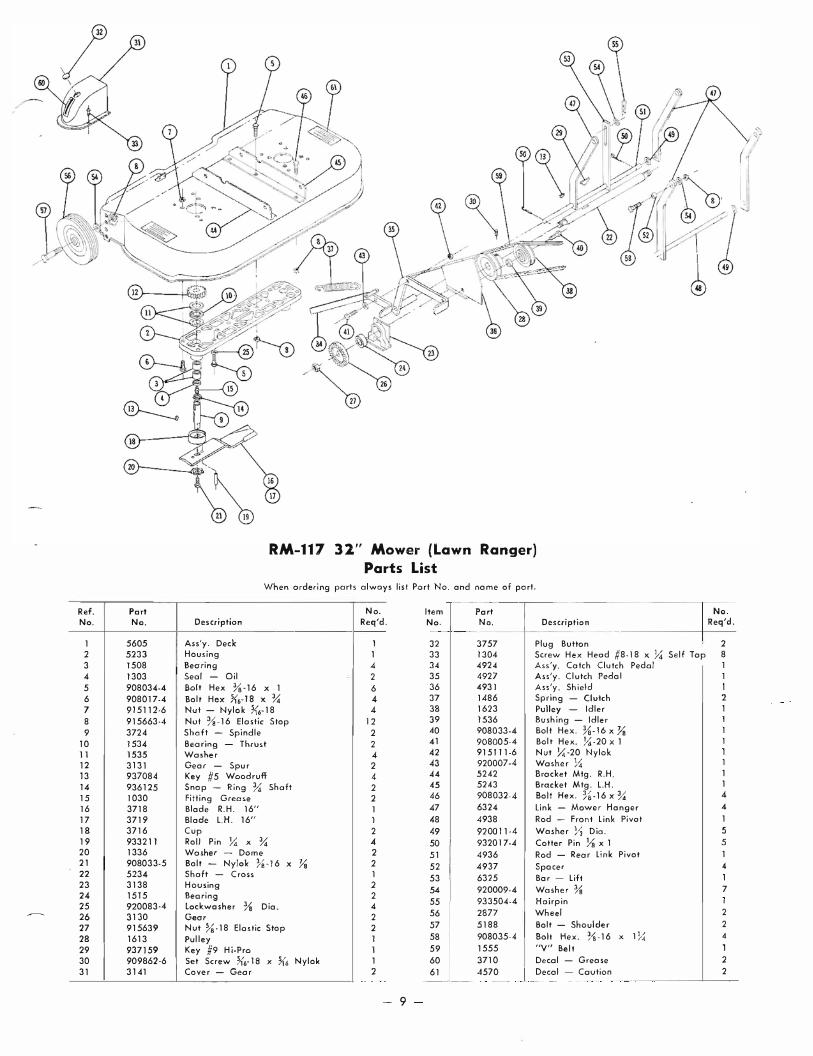
RM-117 32" Mower (Lawn Ranger)
Parts List When ordering parts always list Port No. and nome of port.
No. Item Port Req'd. No. No. Description
--- _.
1 32 3757 Plug Button I N
o Req'd.
2 Housing 1 33 1304- Screw Hex Head #8- 18 x � Self Top 8 Bearing .4 34 4924 Ass'y. Catch Clutch Pedal Seal - Oil 2 35 4927 Ass'y. Clutch Pedal Bolt Hex %-16 x 1 6 36 4931 Ass'y. Sh ield Bolt Hex Jib-IS x % 4 37 1486 Spring - Clutch 2 Nut - Nylo k X'6-18 4 38 1623 Pulley - Idler Nut %-16 Elastic Stop 12 Shoft - Spindle 2 Bearing - Thrust 2 Washer 4-Gear - Spur 2 Key #5 Woodruff 4 Snap - Ring % Shaff 2 Fitting Grease 2
39 1536 Bushing - Idler 40 908033-4 Bolt Hex. %-16 x Ya 41 908005·4 Bolt Hex. �-20 x 1 42 915111-6 Nut �-20 Nylok 43 920007-4 Washer X 44 5242 Brocket Mfg. R.H . 1 45 5243 Bracket Mtg. L.H. 1 46 908032-4- Bolt Hex. % -16 x % 4-
Blade R.H. 16" 1 47 6324 link - Mower Hanger 4
Blade L.H. 16" 1 48 4938 Rod - Front link Pivot 1 Cup 2 49 9200 1 1-4 Washer Y2 Dia. 5 Roll Pin � x % .4 50 932017-4 Cotter Pin Ya x 1 5 Wosher - Dome 2 51 4936 Rod - Rear link Pivot 1 Bolt - Nylok %-16 x Yo 2 Shaft - Cross 1 Housing 2 Bearing 2 lockwosh er % Dia. 4 Gear 2 Nut % ·18 Elastic Stop 2 Pulley 1 Key #9 Hi-Pro 1
52 4937 Spacer 4 53 6325 Bar - Lift 1 54 920009-4 Washer Ys 7 55 933504-4 Hairpin 56 2877 Wheel 2
57 5188 Bolt - Shoulder 2
58 908035-4 Bolt Hex. %-16 x 11/ 4 /4 59 1555 "Y" Belt 1
Set Screw �b- 18 x 1(6 Nylok 1 60 3710 Decal - Grease 2 Cover - Gear 2 61 4570 Decol - Caution 2
----
- 9

I I ,. /
/ J
- 10 -

Ref. Port No. No.
T 3900 2 1533 3 1528 4 150B 5 1532 6 1529 7 1303 B 1 2 32 9 3915
10 3901 11 1530 12 1531 13 3905 14 3906 15 42 35 16 3909 17 908146 18 1 316 19 3904-20 3908 21 933217 22 3522 23 151B 24 3523 25 3907 26 3524 27 3526 28 936125 29 5615 30 5616 31 3503
50SJ TRANSMISSION PARTS LIST
(Order No. 5053 For Complete Transmission)
When ordering parts always list Port No. and Name of Pori.
No. Description Req'd.
Ref. I Port No. No. Description
Case - R.H. 1 32 933156 Roll Pin Ya x 1 Boll Bearing lY2 1.0. 2 3 3 3517 Boll - Shift Stop Bearing - Needle 2 Bearing - Needle � I.D. 2
34 3518 Spring - Shift Stop 35 5614 Pin - Shift Stop
Bearing - Needle 1" 1.0. 1 36 3525 Gear - Cluster Bearing - Needle % 1.0. 2 37 1504 Bearing - Bronze � I.D. Sea! - Oil % Shaft 1 38 3528 Gear - Reduction Pinion Seal - Oil I" Shaft Pin - Dowel Case - LH. Bearing - Needle 1" 1.0. Bearing - Needle % 1.0. Case - Differential Gee r - Differential Bul t Gear - Differential Pinion Shaft Bol t Hex K6-18 x 3� Nul Hug!ock �6' 18 Axle - Rear Gear - Axle Roll Pin � x 1� Gear - In put Bearing - Needle % 1.0. Gear Hi & 2nd Sho ft Spline Gear - Low & Reverse Gear - Pinion - Splined Snap Ring % Truarc Roil - Front Shift Roil - Rear Shift Fork - Shift
STARTER
BLACK
3 2 1 1 1 2 1 4. 5 4 4. 2 2 2 1 1 1 1 1 1
1 1 1 2
LAUSON o HP
39 3527 Gear - Reduction 40 3910 Shaft - (luster Gear 41 937014 Key # 9 Woodruff 42 4204 Gear - Reverse Idler 43 1516 Bushing - Bronze � J.D. 44 3903 Gear - Brake Shaft 45 3902 Drum - Broke 4-6 937022 Key # 15 Woodruff 47 936131 Snap Ring 1" Shoft 48 4437 ASs'y. Broke Band & Lining 49 908002-4- Bolt Hex � ·20 x Ya 50 920081·4 Lockwasher � Dia. 51 943460 Plug � Pipe' 52 943420 Plug Ye Pipe 53 3912 Gasket 54 908043-4 Boll Hex %-16 x 31'2 55 908038·4- Bolt Hex %-16 x 2 56 915113·6 Nut Hex Ys -16 Nylok 57 5279 Ass'y. Sh ift Stick 58 3577 Boot - Shift Stick 59 1239 Sel Screw Dog Point Y.I" -20 60 915111-6 Nut Hex �-20 Nylok 61 1001 Knob
SPARK PL G
8.....ACK
WHITE
x %
IGNITION-STARTER SWITCH Wiring for L-157
-11 -
No. ReCj'd.
2 2 1 1 1 2 1 1 1 2 1 1 1 1 1 1 1 2 2 1 1 1 1 5 6 1 1 1 1 1

ATTACHMENTS A V AILABLE FOR
Models 107 and 157
32/1 LAWN ROLLER (LR-322)
32" SNOW THROWER (STR-324)
38/1 DOZER BLADE (BDR-385)
4 WHEEL UTILITY WAGON (UW-645)
2 WHEEL DUMP TRAILER (LTD-244)
SPIKED DISC AERATOR (SC-152)
SPIKED TOOTH HARROW (PH- 183)
• • •
OPTIONAL ACCESSORIES
TIRE CHAINS (T(·9)
FRONT AND REAR WHEEL DISCS (WD-4)
HEADLIGHT SET (HL-5) - FOR MODEL l-157 ONLY