Hydraulic Siclde Bar Mower - Wheel Horse
10
Hydraulic Siclde Bar Mower HYDRA-SICKLE OPERATION and SERVICE MANUAL REPAIR PARTS LIST SICKLE GROUP and DRIVE GROUP #1.nlOl DIDIER MANUFACTURING CO. 1652 PHILLIPS AVENUE RACINE, WISCONSIN 53403 (414) 634-4887 Form No. 2002 5·73
-
Upload
khangminh22 -
Category
Documents
-
view
0 -
download
0
Transcript of Hydraulic Siclde Bar Mower - Wheel Horse

Hydraulic Siclde Bar Mower
HYDRA-SICKLE
OPERATION and SERVICE MANUAL
REPAIR PARTS LIST
SICKLE GROUP and DRIVE GROUP
#1.nlOl
DIDIER MANUFACTURING CO. 1652 PHILLIPS AVENUE
RACINE, WISCONSIN 53403 (414) 634-4887
Form No. 2002 5·73

GENERAL INFORMATION
This sickle mower unit is easy to operate and as safe as possible. It is designed to handle those hard to cut jobs such as ditches, fence lines and rough ground. We suggest that you carefully read all instructions before you use this mower.
CAUTION
@ Keep safety shield in place over cutter bar and knife at all times when mower is not running .
.. Never ride anyone other than operator on tractor while using this equipment.
III Keep hands and feet away from cutter bar at all times.
tl1 Do not raise cutter bar from horizontal to vertical position while unit is running •
• Never try to adjust or lubricate while unit is running.
(!II Keep hands out of cutting blades when installing 01 removing sickle bar from tractor.
® Never try to mount unit on tractor while tractor is running.
III Never dismount from the tractor while sickle bar is running .
• Disengage power take off and tum off engine before doing any inspecting or adjusting.
~ Never allow anyone to walk alongside of, in front of, or behind sickle bar while it is in motion, or running.

LUBRICATION
This Sickle Bar is lubricated through grease fittings located as follows:
1. Break Back Pivot
2. Main Bar Housing
3. Drive Arm
Refer to photo No. 1 for the location of the grease fittings. Lubricate these fittings after every 3 hours of operation, with a standard grease gun using a general purpose automotive type grease; wipe each fitting with a rag to remove dirt and grit. Avoid forcing dirt into the bearings with the clean grease.
Apply oil to the wear plates, hold down clips, hinge bars, spring ends, and lift lever assembly every two or three hours of operation.
Hydraulic system uses (1) one gallon of API classification MS 10w-30, 10w-40 motor oil, or type A or type A suffix A automatic transmission fluid. Utmost caution should be taken to prevent hydraulic system from becoming contaminated by dirt or other foreign substances. For best results, oil in the hydraulic system should be changed every 50 hours. Oil level should be kept no lower than from 1/4 to 1/2 inch below top of tank.
OPERATION
PHOTO NO 1
(Before starting to cut, make sure all nuts are tight, belt tension is sufficient, and Sickle Bar has been lubricated.)
This unit has been found to cut effectively and last longer when the cutting speed is between full and three-quarters throttle. The ground speed can be determined by the gear the tractor is running in. (Use good judgement to decide which ground speed will be safest for the particular terrain.)
This unit is equipped with a lift lever and a breakback mechanism to help avoid damaging it or the tractor when hitting an obstruction. We advise the area to be cut be inspected prior to cutting and any wire or other foreign objects be removed. Also before cutting, for example: if grass and weeds are laying - cut opposite the direction it is laying.
As mentioned in the preceeding paragraph, the mower is equipped with a breakback mechanism which allows the main bar to swing back when a solid obstacle is strllck. To put bar back in cutting position, simply back tractor up. If this does not work, disengage P.T .. O., shut off engine and manually pull sickle bar forward till it latches into position.
Note: To adjust tension on breakback mechanism to suit, tighten or loosen the two nuts on eye bolt next to hinge assembly.
This unit is also equipped with a transit lock which enables the sickle bar to be locked in the 900
position while enroute or cutting hedges. While the unit is in this position, special care must be taken to make sure the operators hands and feet stay away from the cutting blades.
It is also important that blades be in motion before tractor has begun moving forward.

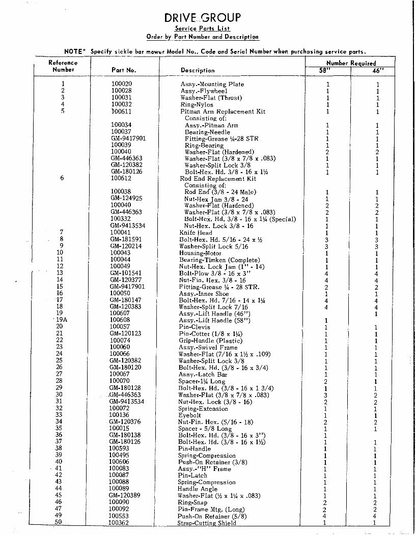
DRIVE GROUP Service Parts Li st
Order by Part Number and Description
NOTE* Specify sickle bar mOWf::r Model No Code and Serial Number wilen purchasing service parts. "
Reference Number Required Number Part No. Description 58" 46"
1 100020 Assy.-Mounting Plate 1 1 2 100028 Assy.-Flywheel 1 1 3 100031 Washer-Flat (Thrust) 1 1 4 100032 Ring-Nylos 1 1 5 100611 Pitman Arm Replacement Kit 1 1
Consisting of: 100034 Assy.-Pitman Arm 1 1 100037 Bearin g-N eedle 1 1 GM-9417901 Fitting-Grease Y4-28 STR 1 1 100039 Ring-Bearing 1 1 100040 Washer-Flat (Hardened) 2 2 GM-446363 Washer-Flat (3/8 x 7/8 x .083) 1 1 GM-120382 Washer-Split Lock 3/8 1 1 GM-180126 Bolt-Hex. Hd. 3/8 - 16 x 1'iS 1 1
6 100612 Rod End Replacemen t Kit
100038 Consisting of: Rod End (3/8 - 24 Male) 1 1
GM-124925 Nut-Hex Jam 3/8 - 24 1 1 100040 W asher-F lat (Hardened) 2 2 GM-446363 Washer-Flat (3/8 x 7/8 x .083) 2 2 100332 Bolt-Hex. Hd. 3/8 - 16 x 1Y4 (Special) 1 1 GM-9413534 Nut-Hex. Lock 3/8 - 16 1 1
7 100041 Knife Head 1 1 8 GM-181591 Bolt-Hex. Hd. 5/16 - 24 x 'is 3 3 9 GM-120214 Washer-Split Lock 5/16 3 3
10 100043 Housing-Motor 1 1 11 100044 Bearing-Timken (Complete) 1 1 12 100049 Nut-Hex. Lock Jam (I" - 14) 1 1 13 GM-101541 Bolt-Plow 3/8 - 16 x 3" 4 4 14 GM-120377 Nut-Fin. Hex. 3/8 - 16 4 4 15 GM-9417901 Fitting-Grease Y4 -28 STR. 2 2 16 100050 Assy.-Inner Shoe 1 1 17 GM-180147 Bolt-Hex. Hd. 7/16 - 14 x 1Y4 4 4 18 GM-120383 Washer-Split Lock 7/16 4 4 19 100607 Assy.-Lift Handle (46") 1
'19A 100608 Assy.-Lift Handle (58") 1 20 100057 Pin-Clevis 1 1 21 GM-120123 Pin-Cotter (1/8 x 1Y4) 1 1 22 100074 Grip-Handle (Plastic) 1 1 23 100060 Assy .-Swi vel Frame 1 1 24 100066 Washer-Flat (7/16 x 1'iS x .109) 1 1 25 GM-120382 Washer-Split Lock 3/8 1 1 26 GM-180120 Bolt-Hex. Hd. (3/8 - 16 x 3/4) 1 1 27 100067 Assy.-Latch Bar 1 1 28 100070 Spacer-1Y4 Long 2 1 29 GM-180128 Bolt-Hex. Hd. (3/8 - 16 x 1 3/4) 1 1 30 "GM-446363 Washer-Flat (3/8 x 7/8 x .083) 3 2 31 GM-9413534 Nut-Hex. Lock (3/8 - 16) 2 2 32 100072 Spring-Extension 1 1 33 100136 Eyebolt 1 1 34 GM-120376 Nut-Fin. Hex. (5/16 - 18) 2 2 35 100015 Spacer - 5/8 Long 1 1 36 GM-180138 Bolt-Hex. Hd. (3/8 - 16 x 3") 1 37 GM-180126 Bolt-Hex. Hd. (3/8 - 16 x 1'iS) 1 1 38 100593 Pin-Handle 1 1 39 100495 Spring-Compression 1 1 40 100606 Push-On Retainer (3/8) 1 1 41 100083 Assy.-"H" Frame 1 1 42 100087 Pin-Latch 1 1 43 100088 Sprin g-Com press ion 1 1 44 100089 Handle Angle 1 1 45 GM-120389 Washer-Flat ('is x 1Y4 x .083) 1 1 46 100090 Ring-Snap 2 2 47 100092 Pin-Frame Mtg. (Long) 2 2 49 100553 Push-On Retainer (5/8) 4 4 50 100362 Strap-Cutting Shield 1 1


SICKLE GROUP Service Ptrts list
Order by Part Number and Description
NOTE* Specify sickle bar mower Model No Code and Serial No when ordering service parts .,
Reference Number Reauired
Number Part No. Description 58" 46"
1 100700 Main Bar with Ledger Plates (46") 1
1A 100678 Main Bar with Ledger Plates (58") 1
2 100701 Ledger Plate Replacement Kit (46") 1
2A 100696 Ledger Plate Replacement Kit (58") 1 Consisting of:
3 100680 Ledger Plate (smooth) 30 24
4 100614 Screw-Tapping 90 72
5 100005 Strap-Wear 2 .f.
5A 100293 Strap-Wear (Short) (Not Shown) 1.
6 100006 Clip-Hold Down 6 5
7 100007 Assy-Outer shoe 1 1
8 100011 Assy-Center shoe 1 1
9 GM-126402 Bolt-Carriage (3/8-16 x 1~) 10 12
10 GM-9413534 Nut-Hex. Lock (3/8 - 16) 15 12 "
11 GM-180126 Bolt-Hex. Hd. (3/8 - 16 x 1V2) 3 3
12 GM-446363 Washer-Flat (3/8 x 7/8 x .083) 7 2
I 13 GM-120382 Washer-Split lock 3/8 3 3
14 GM-120377 Nut-Fin. Hex. (3/8 - 16) 3 3
15 100702 Assy-Knife 46" 1
15A 100697 Assy-Knife 58" 1
16 100703 Knife Section - Replacement Kit (46") 1
16A 100698 Knife Section Replacement Kit (58") 1 Consisting of:
17 100683 Knife Section (3) Hole 3 3
18 100681 Knife Section (2) Hole 26 20
19 100699 Rivet - #6 x 7/16 Round Hd. 58 46
20 100075 Shield-Knife 46" 1
20A 100296 Shield-Knife 58" 1
21 100076 Rubber Band (Knife Shield) 1 1
22 100142 Swath Board 1 1
23 100077 Assy-Divider Rod 1 1
24 100057 Pin-Clevis (3/8 x 1 3/8) 1 1
25 100134 Pin-Hair Cotter 1 1
26 GM-180147 Bolt-Hex. Hd. (7/16 - 14 x 1~) 4
26 GM-180149 Bolt-Hex Hd. (7/16-14 x 11/2) (Fron t) 2
26 GM-180157 Bolt-Hex Hd. (7/16-14 x 2 1/2) (Rear) 2
27 GM-9414073 Nut-Hex Lock (7/16 - 14) 4
28 GM-120389 Washer-Flat (1/2 x 1 1/4 x .109) 2
29 100600 Tube-Reinforcing (rear bolts)
30 GM-180132 Bolt-Hex Hd. (3/8-16 x 2 1/4) 5 (Reinforcing Tube)
2/21/75
'.
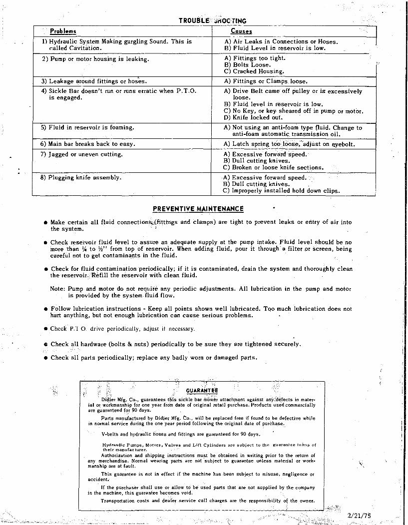
TROUBLE ";iflOC liNG
Problems Causes
1) Hydraulic System Making gurgling Sound. This is A) Air Leaks in Connections or Hoses. r.alled Cavitation. B) Fluid Level in reservoir is low.
2) Pump or motor housing is leaking. A) Fittings too tight. B) Bolts Loose. C) Cracked Housing.
3) Leakage around fittings or hoses. A) Fittings or Clamps loose.
4) Sickle Bar doesn't run or runs erratic when P.T.O. A) Drive Belt came off pulley or is excessively is engaged. loose.
B) Fluid level in reservc>ir is low. C) No Key, or key sheared off in pump or motor. D) Knife locked out.
5) Fluid in reservoir is foaming. A) Not using an anti-foam type fluid. Change to anti-foam automatic transmission oil.
6) Main bar breaks back to easy. A) Latch spring too loose;'adjust on eyebolt.
7) Jagged or uneven cutting. A) Excessive forward speed. B) Dull cutting knives. C) Broken or loose knife sections.
8) Plugging knife assembly. A) Excessi ve forward speed. B) Dull cutting knives. C) Improperly installed hold down clips.
PREVENTIVE MAINTENANCE
• Make certain all fluid connection;sr.lijtti:rigs and clamps) are tight to prevent leaks or entry of air into the system.
• Check reservoir fluid level to assure an adequate supply at the pump intake. Fluid level should be no more than y.. to \12" from top of reservoir. When adding fluid, pour it through a filter or screen, being careful not to get contaminants in the fluid.
• Check for fluid contamination periodically; if it is contaminated, drain the system and thoroughly clean the reservoir. Refill the reservoir with clean fluid.
Note: Pump and motor do not require any periodic adjustments. All lubrication in the pump and motor is provided by the system fluid flow.
• Follow lubrication instructions· Keep all points shown well lubricated. TQo much lubrication does not hurt anything, but not enough lubrication can cause serious problems.
• Check P.TO drive periodically, adjust if necessary.
• Check all hardware (bolts & nuts) peri9dically to be sure they are tightened securely.
• Check all parts periodically; replace any badly worn or damaged parts.
c. "
GUARA}JTEE
DJai~r Mfg. Co., guarantees this sickle bar m'0";';.~·r attach:ment against any:',d~fects in material or wo'rkmanship for one year from date of original retail purchase. Products used commercially are guaranteed f<:>! 90 days.
Parts manufactured by Didier Mfg. Co., will be replaced free if found to be defective while in normal service during the one year period following the original date of purchase.
V-belts and hydraulic hoses and fittings are guaranteed for 90 days.
Hydraulic Pwnps, Motor's, Valves and'Lift Cylinders are subject to the guarantee terms of their manufac turer.
Authorization and shipping instructions must be obtained in writing prior to the return of any merchandise. Normal wearing parts are not subject to guarantee unless material or workmanship are at fault.
This guarantee is not in effect if the machine has been subject to misuse, negligence or accident.
If the purchaser shall use or allow to be used parts that are not supplied by the company in the machine, this guarantee becomes void. .
Transportation costs and dealer service call charges are the responsibility of the owner.
2/21/75 ""'.--....-',..-~-"', _ _ .....;,r---.......' __ ~~--'
,

WHEEL HORSE 10751 FRAME GROUP
Repair Parts List
Order by Part Number and Description
Reference Part No. Number No. Desc ri ption Required
1 100424 Assy. - Main Frame (Welded) 1 2 GM-180122 Bolt - 3/8-16 x I" Hx. Hd. 6 3 GM-120388 Washer - Flat (7/16 x I" x .083) 12 4 GM-9413534 Nut - Hex. Lock 3/8-16 7 5 100092 Pin - Mounting (Long) 1 6 100397 Torsion Spring (R.H.) 1 7 100398 Torsion Spring (L.H.) 1 8 GM-120123 Pin - Cotter (1/8 x llJ1) 2 9 100109 Tank - Reservoir (I-Gallon) 1
10 GM-126705 Bolt - 3/8-16 x 3" Carr. 1 11 GM-120377 Nut - Lt. Hex. 3/8-16 13 12 GM-180134 Bolt - 3/8-16 x 2~ Hx. Hd. 2 13 100135 Spring - Extension 1 14 100136 Eyebolt 1 15 GM-120376 Nut - Lt. Hex. 5/16-18 2 16 100057 Pin - Clevis (3/8 x 1 3/8) 1 17 GM-446363 Washer - Flat (3/8 x 7/8 x .083) 2 18 100134 Pin - Hair Cotter (Small) 3 19 90030 Pin - Hair Cotter (Large) 2 20 100304 Pin - Clevis (~ x 1~) 2 21 100434 Assy. - Rear Mtg. Brk't. (Welded) (L.H.) 1 22 100437 Assy. - Rear Mtg. Brk't. (Welded) (R.H.) 1
I 23 GM-180124 Bolt - 3/8-16 x llJ1 Hx. Hd. 4 24 100438 Rod - Idler Pulley 1 25 100439 Angle - Pulley Mtg. 1 26 80070 Assy. - Idler Pulley (2-3/4 0.0. Flat x
3/8 Bore) 1 27 GM-180126 Bolt - 3/8-16 x 1~ Hex. Hd. 1 28 100132 Handle - Adjusting 1 29 100149 Pump - Hyd. 22YB-L.H. 1 30 100116 Pulley (4~ 0.0. - "A" Section) 1 31 GM-115321 Screw - Set 5/16-18 x 5/16 Sk't. Hd. -
Cup Pt. 2 32 100117 Key - 1t5 Woodruff 2 33 100422 Fitting - 45 0 Male Elbow (3/8 NPT x 3/4-16
lIC) 1 34 100211 Hose - Suction (5/8 x 18" Lg.) 1 35 100119 Clamp - Hose 3 36 100244 Hose - Return (5/8 x 48" bg.) 1 37 100122 Fitting - 900 Street Elbow (~ NPT) 1 38 100180 Hose - Pressure (3/8 x 50" Lg.) 1 39 100126 Fitting - 900 Street Elbow (3/8 NPT) 1 40 100176 Fitting - 900 Male Elbow (3/8 NPT x
9/16-18 lIC) 1 41 100123 Motor - Hyd. (73YB - L.H.) 1 42 100305 V-Belt (XDV-48-990) 1

OPERATION
After mounting unit to tractor, you are ready to check the drive operation.
The first thing to do is to check and be sure that the fluid reservoir is full. Next recheck V-belt for proper tension. Drop main bar to horizontal cutting position on ground and remove sheet metal knife shield and rubber band holding it in place. Put them some place where you can easily find them later. Note: This shield should be kept on unit at all times when mower is not in use.
Start tractor engine; be certain P.T.O. is disengaged. After engine is warmed up, and with throttle set in idle position, engage tractor P T .. O. The sickle blade will start to run slowly within a second or two, as soon as fluid flOm the reservoir fills the hydraulic pumps and hoses. Let unit run like this for 2 to 3 minutes for initial break in. Disengage P.T.O. and shut tractor engine off.
Check hoses, fittings and pumps for leaks. Tighten any loose fittings or clamps.
Check reservoir and add fluid if level is below 1/4 to 1/2 inch from top of tank.
The sickle bar mower is now ready for operation. Tractor throttle should be set at from 3/4 to full throttle during operation. This setting will give you the best cutting speed and allow for maximum ground speed on almost all applications.
Form 2008
IMPORTANT: Always be sure that fluid level in reservoir is maintained .. Fluid level should not be below 1/4 to 1/2 inch from top of tank.
10-73