Simple determination of the axial stiffness for large - CORE
Upload
independentCategory
view
2download
0
Composites Science and Technology 97 (2014) 12–18
Contents lists available at ScienceDirect
Composites Science and Technology
journal homepage: www.elsevier .com/ locate /compsci tech
Variable stiffness characteristics of embeddable multi-stable composites
http://dx.doi.org/10.1016/j.compscitech.2014.03.0170266-3538/� 2014 Elsevier Ltd. All rights reserved.
⇑ Corresponding author. Tel.: +41 0446322675; fax: +41 0446331125.E-mail address: [email protected] (A.F. Arrieta).
1 These authors contributed equally to this work.
Andres F. Arrieta ⇑,1, Izabela K. Kuder 1, Tobias Waeber, Paolo ErmanniLaboratory of Composite Materials and Adaptive Structures, ETH Zurich, Leonhardstrasse 27, Zurich CH-8092, Switzerland
a r t i c l e i n f o
Article history:Received 17 December 2013Received in revised form 21 March 2014Accepted 23 March 2014Available online 1 April 2014
Keywords:A. Smart materialsA. Flexible compositesB. Non-linear behaviourC. Modelling
a b s t r a c t
The possibility to achieve shape adaptation provides structural systems with the potential to adjust foroptimal operation in a wide range of conditions. The formidable challenges posed by shape adaptation,and particularly in morphing applications, can be potentially addressed through the development of dis-tributed compliance systems featuring highly directional structural properties. These characteristics canbe further enhanced by embedding in such systems elements featuring variable stiffness. In this paper, anovel type of embeddable variable stiffness elements exploiting thermally-induced multi-stability inunsymmetrically laminated composites is presented. A tailored lay-up exhibiting spatially distirbutedstacking sequences is implemented to achieve multi-stability even when restricting two opposing edges.The difference between the structural responses leading exhibited by the multiple stable shapes of thedesigned composites are numerically investigated. The restoring force for each stable state is examinedyielding a significant variability in the stiffness. Experimental specimens are manufactured and testedshowing good agreement with the numerical results, validating the proposed variable stiffnessimplementation.
� 2014 Elsevier Ltd. All rights reserved.
1. Introduction
The ability to operate optimally in diverse conditions has led tothe idea of introducing the capability to adjust the properties ofengineering systems in response to environmental changes, result-ing in the field of adaptive structures [1]. A set of properties partic-ularly difficult to be adapted, are those concerned with shapevariation of structural elements. This problem is exemplified con-formal change of the shape of aerospace structures, widely knownin the engineering community as morphing. Morphing requiresstructures exhibiting highly directional properties to meet the con-flicting requirements of load-carrying capabilities along the direc-tion of the loads, high compliance in the directions of shapeadaptation, while maintaining light-weight constructional charac-teristics [2]. Several challenges remain to be addressed for theimplementation of this promising technology. Distributed compli-ance structural systems are a promising solution to the formidablechallenges presented by shape adaptation requirements, particu-larly those posed by morphing applications [3,4]. A new trend tosignificantly augment the directionality of the structural propertiesof such systems is to embed elements capable of varying their stiff-ness [5]. The ability to change the structural response of certain
components in distributed compliance systems allows for a higherdegree of decoupling between the compliance and stiffnessrequirements. Composite laminates exhibiting multiple staticallystable shapes are good candidates to serve as variable stiffness ele-ments embedded within distributed compliance structures [6–8].Indeed, a significantly different directional structural responsecharacterises each equilibrium configuration. The capability ofadopting a number of statically stable states has brought thesestructures into the focus of extensive research in recent years. Sev-eral types of systems including biological [9], and synthetic [10–12] exploit this phenomenon to achieve unattainable perfor-mances with conventional structures. Multi-stability in compositematerials arises from an induced stress field that can be realised byseveral mechanisms, including unsymmetrical lamination [13], tai-lored lay-up [14], pre-stressed cylinders [10], fibre pre-stressing[15] and thickness variation [16]. Amongst multi-stable structures,multi-stable composite laminates have been considered for morp-hing applications due to the large deformations exhibited whenchanging between stable configurations [17–20]. Although suchstructures have shown promising results, the discrete nature ofthe achievable equilibrium shapes restricts the range of applicabil-ity of multi-stable components as a means to obtain large deflec-tions in load carrying elements. The possibility offered by multi-stable components to achieve different structural properties foreach of the attainable stable configurations, allowing for the reali-sation of load-carrying variable stiffness elements, has not been
A.F. Arrieta et al. / Composites Science and Technology 97 (2014) 12–18 13
thus far explored. Taking advantage these characteristic, multi-sta-ble elements can be designed to exhibit variable stiffness proper-ties arising from the different structural response of the stableconfigurations.
In this paper, a novel class of variable stiffness elements basedon exploiting the significantly different structural characteristicsassociated to the stable configurations of multi-stable compositesis introduced. The components herein presented are specificallydesigned to be embeddable into larger structures, thus providingthe complete system with passive variable stiffness capabilities.In particular, the designed multi-stable laminates allow for inte-gration without conventional fixation parts, which is particularlysuitable to enhance the structural directional response of distrib-uted compliance systems through the added capability of stiffnessadaptation. A tailored lay-out featuring several sections with dif-ferent stacking sequences is designed achieving both a significantdifference in the structural response, and the capability to embedthe components into distributed compliance systems. Thermalstresses induced during the cool-down process arising from sec-tions of unsymmetric lamination are exploited to realise thedesired multi-stable behaviour. The Finite Element Method (FEM)is employed to simulate and design the variability of the stiffnesscharacteristics associated to each stable configuration. The roomtemperature shapes of the designed multi-stable components arecalculated with the FEM showing good agreement with manufac-tured specimens. The structural response of the stable configura-tions is studied for relevant load cases both numerically andexperimentally. Finite Element (FE) simulations demonstrate sig-nificant variability in the stiffnesses associated to each stable con-figuration. Tests on experimental specimens show a close matchwith the FE results, validating the numerical analyses. The realisa-tion of purely elastic, passive, embeddable load carrying variablestiffness elements can be potentially used to significantly alterthe structural response of a load-carrying system in a simple androbust fashion. The variable stiffness offered by the presentedmulti-stable components can be exploited to enhance the direc-tionality of the structural characteristics of systems for whichstructural efficiency is of paramount importance, as for instancein morphing structures. Consequently, a reduction of the actuationrequirements to obtain large deflections, or altogether passivemorphing exploiting the external forces on the structure to inducedesired shape adaptation, can be achieved. Furthermore, as multi-stability in these structures is obtained from passive means, thecapability to achieve significant variation in the structuralresponse can be realised in a robust manner. Moreover, the stiff-ness variability can be implemented on applications where struc-tural hysteresis cycles are required, as for instance in energydissipation applications.
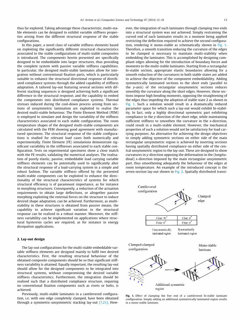
Fig. 1. Effect of clamping the free end of a cantilevered bi-stable laminateconfiguration. Simply adding an additional symmetrically laminated region resultsin a mono-stable laminate.
2. Lay-out design
The lay-out configurations for the multi-stable embeddable var-iable stiffness elements are designed mainly to fulfil two desiredcharacteristics. First, the resulting structural behaviour of theobtained composite components should be so that significant stiff-ness variability is attained. Equally important, the resulting lay-outshould allow for the designed components to be integrated intostructural systems, without compromising the desired variablestiffness characteristics. Furthermore, the integration should berealised such that a distributed compliance structure, requiringno conventional fixation components such as rivets or bolts, isachieved.
Previously, multi-stable laminates in a cantilevered configura-tion, i.e. with one edge completely clamped, have been obtainedthrough a symmetric-unsymmetric stacking lay-out [7,21]. How-
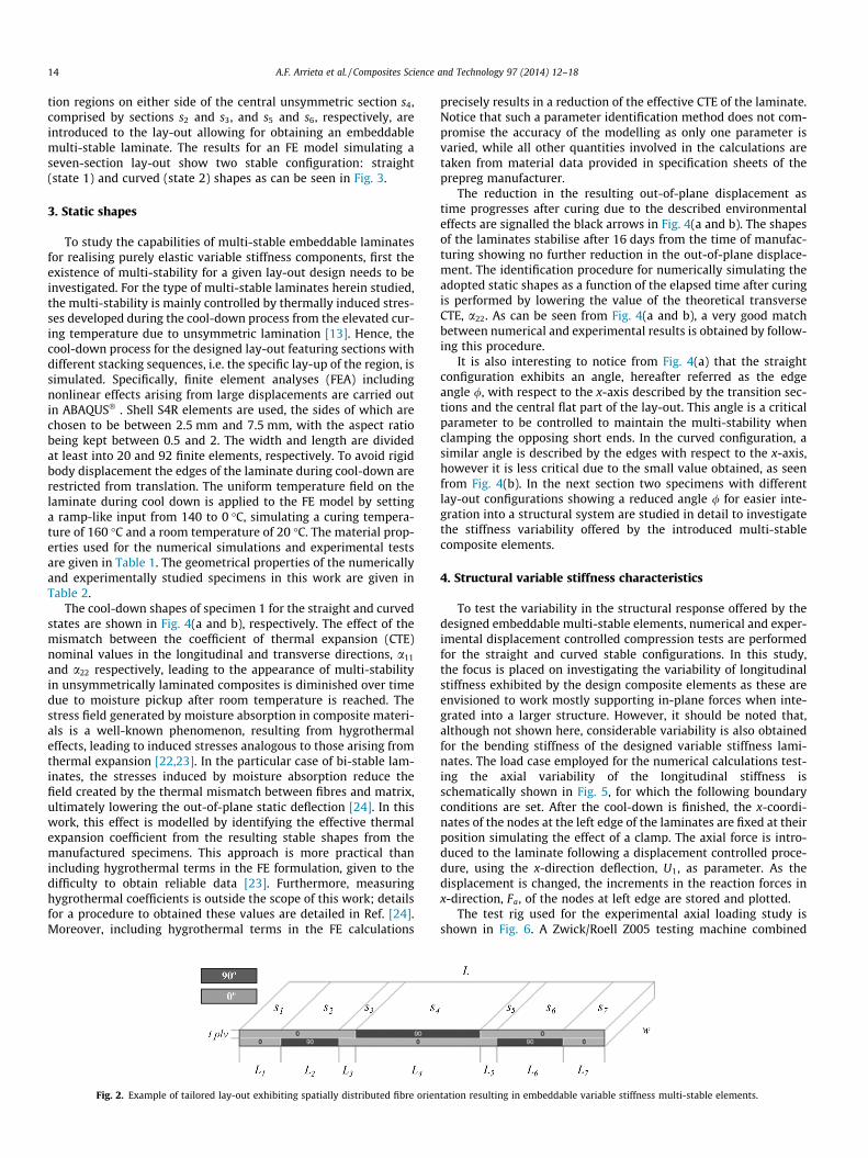
ever, the integration of such laminates through clamping two endsinto a structural system was not achieved. Simply restraining thecurved end of such laminates results in a moment being appliedrestricting the deflection required to achieve the second configura-tion, rendering it mono-stable as schematically shown in Fig. 1.Therefore, a smooth transition reducing the curvature of the edgesto be clamped is necessary to maintain multi-stability whenembedding the laminates. This is accomplished by designing com-pliant edges allowing for the introduction of boundary forces andmoments to the multi-stable laminates. Starting from a rectangularbi-stable section, appropriate elastic boundaries allowing for asmooth reduction of the curvatures in both stable states are addedto achieve the objective of the component embeddability. Addingsymmetrically laminated sections to the short ends (parallel tothe y-axis) of the rectangular unsymmetric sections reducessmoothly the curvature along the short edges. However, these sec-tions impose high bending moments, opposing the straightening ofthe edges thus impeding the adoption of stable state 2 as shown inFig. 1. Such a solution would result in a dramatically reducedparameter space for which such a lay-out would exhibit bi-stabil-ity. In fact, only a highly directional symmetric part exhibitingcompliance in the y-direction of the short edge, while maintainingsufficient stiffness to smoothen the curvature in the x-direction,could result in a multi-stable element. However, the mechanicalproperties of such a solution would not be satisfactory for load car-rying purposes. An alternative for achieving the design objectivesto simply adding symmetric sections on either side of the mainrectangular unsymmetric region is achieved by inserting sectionshaving spatially distributed compliance on either side of the cen-tral unsymmetric region to the lay-out. These are designed to showcurvatures in y-direction opposing the deformation in the (longitu-dinal) x-direction imposed by the main rectangular unsymmetricpart, thus smoothening adequately the behaviour of the edges atroom temperature. An example of the introduced concept is theseven-section lay-out shown in Fig. 2. Spatially distributed transi-
14 A.F. Arrieta et al. / Composites Science and Technology 97 (2014) 12–18
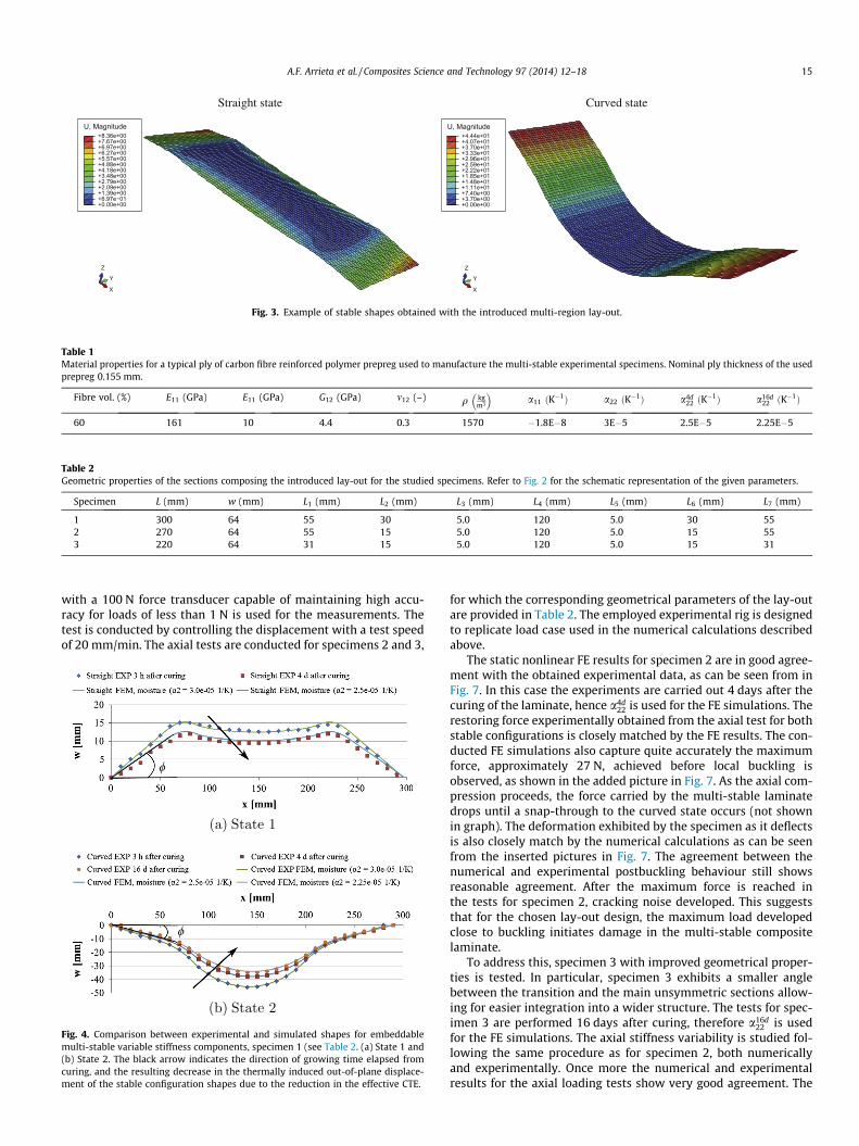
tion regions on either side of the central unsymmetric section s4,comprised by sections s2 and s3, and s5 and s6, respectively, areintroduced to the lay-out allowing for obtaining an embeddablemulti-stable laminate. The results for an FE model simulating aseven-section lay-out show two stable configuration: straight(state 1) and curved (state 2) shapes as can be seen in Fig. 3.
3. Static shapes
To study the capabilities of multi-stable embeddable laminatesfor realising purely elastic variable stiffness components, first theexistence of multi-stability for a given lay-out design needs to beinvestigated. For the type of multi-stable laminates herein studied,the multi-stability is mainly controlled by thermally induced stres-ses developed during the cool-down process from the elevated cur-ing temperature due to unsymmetric lamination [13]. Hence, thecool-down process for the designed lay-out featuring sections withdifferent stacking sequences, i.e. the specific lay-up of the region, issimulated. Specifically, finite element analyses (FEA) includingnonlinear effects arising from large displacements are carried outin ABAQUS� . Shell S4R elements are used, the sides of which arechosen to be between 2.5 mm and 7.5 mm, with the aspect ratiobeing kept between 0.5 and 2. The width and length are dividedat least into 20 and 92 finite elements, respectively. To avoid rigidbody displacement the edges of the laminate during cool-down arerestricted from translation. The uniform temperature field on thelaminate during cool down is applied to the FE model by settinga ramp-like input from 140 to 0 �C, simulating a curing tempera-ture of 160 �C and a room temperature of 20 �C. The material prop-erties used for the numerical simulations and experimental testsare given in Table 1. The geometrical properties of the numericallyand experimentally studied specimens in this work are given inTable 2.
The cool-down shapes of specimen 1 for the straight and curvedstates are shown in Fig. 4(a and b), respectively. The effect of themismatch between the coefficient of thermal expansion (CTE)nominal values in the longitudinal and transverse directions, a11
and a22 respectively, leading to the appearance of multi-stabilityin unsymmetrically laminated composites is diminished over timedue to moisture pickup after room temperature is reached. Thestress field generated by moisture absorption in composite materi-als is a well-known phenomenon, resulting from hygrothermaleffects, leading to induced stresses analogous to those arising fromthermal expansion [22,23]. In the particular case of bi-stable lam-inates, the stresses induced by moisture absorption reduce thefield created by the thermal mismatch between fibres and matrix,ultimately lowering the out-of-plane static deflection [24]. In thiswork, this effect is modelled by identifying the effective thermalexpansion coefficient from the resulting stable shapes from themanufactured specimens. This approach is more practical thanincluding hygrothermal terms in the FE formulation, given to thedifficulty to obtain reliable data [23]. Furthermore, measuringhygrothermal coefficients is outside the scope of this work; detailsfor a procedure to obtained these values are detailed in Ref. [24].Moreover, including hygrothermal terms in the FE calculations
Fig. 2. Example of tailored lay-out exhibiting spatially distributed fibre orien
precisely results in a reduction of the effective CTE of the laminate.Notice that such a parameter identification method does not com-promise the accuracy of the modelling as only one parameter isvaried, while all other quantities involved in the calculations aretaken from material data provided in specification sheets of theprepreg manufacturer.
The reduction in the resulting out-of-plane displacement astime progresses after curing due to the described environmentaleffects are signalled the black arrows in Fig. 4(a and b). The shapesof the laminates stabilise after 16 days from the time of manufac-turing showing no further reduction in the out-of-plane displace-ment. The identification procedure for numerically simulating theadopted static shapes as a function of the elapsed time after curingis performed by lowering the value of the theoretical transverseCTE, a22. As can be seen from Fig. 4(a and b), a very good matchbetween numerical and experimental results is obtained by follow-ing this procedure.
It is also interesting to notice from Fig. 4(a) that the straightconfiguration exhibits an angle, hereafter referred as the edgeangle /, with respect to the x-axis described by the transition sec-tions and the central flat part of the lay-out. This angle is a criticalparameter to be controlled to maintain the multi-stability whenclamping the opposing short ends. In the curved configuration, asimilar angle is described by the edges with respect to the x-axis,however it is less critical due to the small value obtained, as seenfrom Fig. 4(b). In the next section two specimens with differentlay-out configurations showing a reduced angle / for easier inte-gration into a structural system are studied in detail to investigatethe stiffness variability offered by the introduced multi-stablecomposite elements.
4. Structural variable stiffness characteristics
To test the variability in the structural response offered by thedesigned embeddable multi-stable elements, numerical and exper-imental displacement controlled compression tests are performedfor the straight and curved stable configurations. In this study,the focus is placed on investigating the variability of longitudinalstiffness exhibited by the design composite elements as these areenvisioned to work mostly supporting in-plane forces when inte-grated into a larger structure. However, it should be noted that,although not shown here, considerable variability is also obtainedfor the bending stiffness of the designed variable stiffness lami-nates. The load case employed for the numerical calculations test-ing the axial variability of the longitudinal stiffness isschematically shown in Fig. 5, for which the following boundaryconditions are set. After the cool-down is finished, the x-coordi-nates of the nodes at the left edge of the laminates are fixed at theirposition simulating the effect of a clamp. The axial force is intro-duced to the laminate following a displacement controlled proce-dure, using the x-direction deflection, U1, as parameter. As thedisplacement is changed, the increments in the reaction forces inx-direction, Fa, of the nodes at left edge are stored and plotted.
The test rig used for the experimental axial loading study isshown in Fig. 6. A Zwick/Roell Z005 testing machine combined
tation resulting in embeddable variable stiffness multi-stable elements.
U, Magnitude
+0.00e+00+6.97e−01+1.39e+00+2.09e+00+2.79e+00+3.48e+00+4.18e+00+4.88e+00+5.57e+00+6.27e+00+6.97e+00+7.67e+00+8.36e+00
X
Y
Z
Straight state
U, Magnitude
+0.00e+00+3.70e+00+7.40e+00+1.11e+01+1.48e+01+1.85e+01+2.22e+01+2.59e+01+2.96e+01+3.33e+01+3.70e+01+4.07e+01+4.44e+01
X
Y
Z
Curved state
Fig. 3. Example of stable shapes obtained with the introduced multi-region lay-out.
Table 1Material properties for a typical ply of carbon fibre reinforced polymer prepreg used to manufacture the multi-stable experimental specimens. Nominal ply thickness of the usedprepreg 0.155 mm.
Fibre vol. (%) E11 (GPa) E11 (GPa) G12 (GPa) m12 (–) q kgm3
� �a11 ðK�1Þ a22 ðK�1Þ a4d
22 ðK�1Þ a16d
22 ðK�1Þ
60 161 10 4.4 0.3 1570 �1.8E�8 3E�5 2.5E�5 2.25E�5
Table 2Geometric properties of the sections composing the introduced lay-out for the studied specimens. Refer to Fig. 2 for the schematic representation of the given parameters.
Specimen L (mm) w (mm) L1 (mm) L2 (mm) L3 (mm) L4 (mm) L5 (mm) L6 (mm) L7 (mm)
1 300 64 55 30 5.0 120 5.0 30 552 270 64 55 15 5.0 120 5.0 15 553 220 64 31 15 5.0 120 5.0 15 31
A.F. Arrieta et al. / Composites Science and Technology 97 (2014) 12–18 15
with a 100 N force transducer capable of maintaining high accu-racy for loads of less than 1 N is used for the measurements. Thetest is conducted by controlling the displacement with a test speedof 20 mm/min. The axial tests are conducted for specimens 2 and 3,
Fig. 4. Comparison between experimental and simulated shapes for embeddablemulti-stable variable stiffness components, specimen 1 (see Table 2. (a) State 1 and(b) State 2. The black arrow indicates the direction of growing time elapsed fromcuring, and the resulting decrease in the thermally induced out-of-plane displace-ment of the stable configuration shapes due to the reduction in the effective CTE.
for which the corresponding geometrical parameters of the lay-outare provided in Table 2. The employed experimental rig is designedto replicate load case used in the numerical calculations describedabove.
The static nonlinear FE results for specimen 2 are in good agree-ment with the obtained experimental data, as can be seen from inFig. 7. In this case the experiments are carried out 4 days after thecuring of the laminate, hence a4d
22 is used for the FE simulations. Therestoring force experimentally obtained from the axial test for bothstable configurations is closely matched by the FE results. The con-ducted FE simulations also capture quite accurately the maximumforce, approximately 27 N, achieved before local buckling isobserved, as shown in the added picture in Fig. 7. As the axial com-pression proceeds, the force carried by the multi-stable laminatedrops until a snap-through to the curved state occurs (not shownin graph). The deformation exhibited by the specimen as it deflectsis also closely match by the numerical calculations as can be seenfrom the inserted pictures in Fig. 7. The agreement between thenumerical and experimental postbuckling behaviour still showsreasonable agreement. After the maximum force is reached inthe tests for specimen 2, cracking noise developed. This suggeststhat for the chosen lay-out design, the maximum load developedclose to buckling initiates damage in the multi-stable compositelaminate.
To address this, specimen 3 with improved geometrical proper-ties is tested. In particular, specimen 3 exhibits a smaller anglebetween the transition and the main unsymmetric sections allow-ing for easier integration into a wider structure. The tests for spec-imen 3 are performed 16 days after curing, therefore a16d
22 is usedfor the FE simulations. The axial stiffness variability is studied fol-lowing the same procedure as for specimen 2, both numericallyand experimentally. Once more the numerical and experimentalresults for the axial loading tests show very good agreement. The
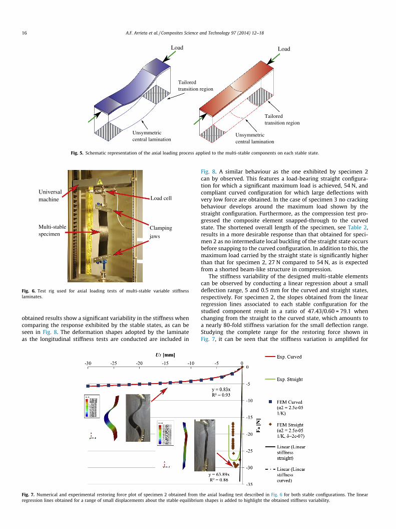
Load
Unsymmetriccentral lamination
Load
Unsymmetriccentral lamination
Tailoredtransition region
Tailoredtransition region
Fig. 5. Schematic representation of the axial loading process applied to the multi-stable components on each stable state.
Clamping
jaws
Universalmachine Load cell
Multi-stablespecimen
Fig. 6. Test rig used for axial loading tests of multi-stable variable stiffnesslaminates.
16 A.F. Arrieta et al. / Composites Science and Technology 97 (2014) 12–18
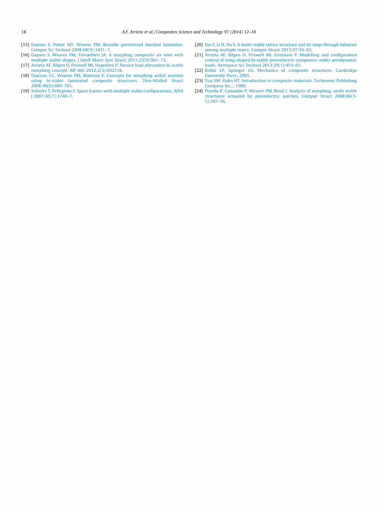
obtained results show a significant variability in the stiffness whencomparing the response exhibited by the stable states, as can beseen in Fig. 8. The deformation shapes adopted by the laminateas the longitudinal stiffness tests are conducted are included in
Fig. 7. Numerical and experimental restoring force plot of specimen 2 obtained fromregression lines obtained for a range of small displacements about the stable equilibriu
Fig. 8. A similar behaviour as the one exhibited by specimen 2can by observed. This features a load-bearing straight configura-tion for which a significant maximum load is achieved, 54 N, andcompliant curved configuration for which large deflections withvery low force are obtained. In the case of specimen 3 no crackingbehaviour develops around the maximum load shown by thestraight configuration. Furthermore, as the compression test pro-gressed the composite element snapped-through to the curvedstate. The shortened overall length of the specimen, see Table 2,results in a more desirable response than that obtained for speci-men 2 as no intermediate local buckling of the straight state occursbefore snapping to the curved configuration. In addition to this, themaximum load carried by the straight state is significantly higherthan that for specimen 2, 27 N compared to 54 N, as is expectedfrom a shorted beam-like structure in compression.
The stiffness variability of the designed multi-stable elementscan be observed by conducting a linear regression about a smalldeflection range, 5 and 0.5 mm for the curved and straight states,respectively. For specimen 2, the slopes obtained from the linearregression lines associated to each stable configuration for thestudied component result in a ratio of 47.43/0.60 = 79.1 whenchanging from the straight to the curved state, which amounts toa nearly 80-fold stiffness variation for the small deflection range.Studying the complete range for the restoring force shown inFig. 7, it can be seen that the stiffness variation is amplified for
the axial loading test described in Fig. 6 for both stable configurations. The linearm shapes is added to highlight the obtained stiffness variability.
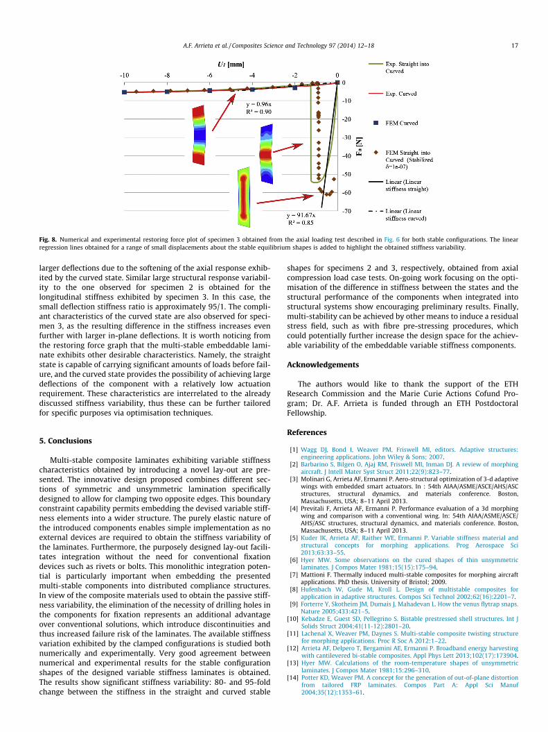
Fig. 8. Numerical and experimental restoring force plot of specimen 3 obtained from the axial loading test described in Fig. 6 for both stable configurations. The linearregression lines obtained for a range of small displacements about the stable equilibrium shapes is added to highlight the obtained stiffness variability.
A.F. Arrieta et al. / Composites Science and Technology 97 (2014) 12–18 17
larger deflections due to the softening of the axial response exhib-ited by the curved state. Similar large structural response variabil-ity to the one observed for specimen 2 is obtained for thelongitudinal stiffness exhibited by specimen 3. In this case, thesmall deflection stiffness ratio is approximately 95/1. The compli-ant characteristics of the curved state are also observed for speci-men 3, as the resulting difference in the stiffness increases evenfurther with larger in-plane deflections. It is worth noticing fromthe restoring force graph that the multi-stable embeddable lami-nate exhibits other desirable characteristics. Namely, the straightstate is capable of carrying significant amounts of loads before fail-ure, and the curved state provides the possibility of achieving largedeflections of the component with a relatively low actuationrequirement. These characteristics are interrelated to the alreadydiscussed stiffness variability, thus these can be further tailoredfor specific purposes via optimisation techniques.
5. Conclusions
Multi-stable composite laminates exhibiting variable stiffnesscharacteristics obtained by introducing a novel lay-out are pre-sented. The innovative design proposed combines different sec-tions of symmetric and unsymmetric lamination specificallydesigned to allow for clamping two opposite edges. This boundaryconstraint capability permits embedding the devised variable stiff-ness elements into a wider structure. The purely elastic nature ofthe introduced components enables simple implementation as noexternal devices are required to obtain the stiffness variability ofthe laminates. Furthermore, the purposely designed lay-out facili-tates integration without the need for conventional fixationdevices such as rivets or bolts. This monolithic integration poten-tial is particularly important when embedding the presentedmulti-stable components into distributed compliance structures.In view of the composite materials used to obtain the passive stiff-ness variability, the elimination of the necessity of drilling holes inthe components for fixation represents an additional advantageover conventional solutions, which introduce discontinuities andthus increased failure risk of the laminates. The available stiffnessvariation exhibited by the clamped configurations is studied bothnumerically and experimentally. Very good agreement betweennumerical and experimental results for the stable configurationshapes of the designed variable stiffness laminates is obtained.The results show significant stiffness variability: 80- and 95-foldchange between the stiffness in the straight and curved stable
shapes for specimens 2 and 3, respectively, obtained from axialcompression load case tests. On-going work focusing on the opti-misation of the difference in stiffness between the states and thestructural performance of the components when integrated intostructural systems show encouraging preliminary results. Finally,multi-stability can be achieved by other means to induce a residualstress field, such as with fibre pre-stressing procedures, whichcould potentially further increase the design space for the achiev-able variability of the embeddable variable stiffness components.
Acknowledgements
The authors would like to thank the support of the ETHResearch Commission and the Marie Curie Actions Cofund Pro-gram; Dr. A.F. Arrieta is funded through an ETH PostdoctoralFellowship.
References
[1] Wagg DJ, Bond I, Weaver PM, Friswell MI, editors. Adaptive structures:engineering applications. John Wiley & Sons; 2007.
[2] Barbarino S, Bilgen O, Ajaj RM, Friswell MI, Inman DJ. A review of morphingaircraft. J Intell Mater Syst Struct 2011;22(9):823–77.
[3] Molinari G, Arrieta AF, Ermanni P. Aero-structural optimization of 3-d adaptivewings with embedded smart actuators. In : 54th AIAA/ASME/ASCE/AHS/ASCstructures, structural dynamics, and materials conference. Boston,Massachusetts, USA; 8–11 April 2013.
[4] Previtali F, Arrieta AF, Ermanni P. Performance evaluation of a 3d morphingwing and comparison with a conventional wing. In: 54th AIAA/ASME/ASCE/AHS/ASC structures, structural dynamics, and materials conference. Boston,Massachusetts, USA; 8–11 April 2013.
[5] Kuder IK, Arrieta AF, Raither WE, Ermanni P. Variable stiffness material andstructural concepts for morphing applications. Prog Aerospace Sci2013;63:33–55.
[6] Hyer MW. Some observations on the cured shapes of thin unsymmetriclaminates. J Compos Mater 1981;15(15):175–94.
[7] Mattioni F. Thermally induced multi-stable composites for morphing aircraftapplications. PhD thesis. University of Bristol; 2009.
[8] Hufenbach W, Gude M, Kroll L. Design of multistable composites forapplication in adaptive structures. Compos Sci Technol 2002;62(16):2201–7.
[9] Forterre Y, Skotheim JM, Dumais J, Mahadevan L. How the venus flytrap snaps.Nature 2005;433:421–5.
[10] Kebadze E, Guest SD, Pellegrino S. Bistable prestressed shell structures. Int JSolids Struct 2004;41(11-12):2801–20.
[11] Lachenal X, Weaver PM, Daynes S. Multi-stable composite twisting structurefor morphing applications. Proc R Soc A 2012:1–22.
[12] Arrieta AF, Delpero T, Bergamini AE, Ermanni P. Broadband energy harvestingwith cantilevered bi-stable composites. Appl Phys Lett 2013;102(17):173904.
[13] Hyer MW. Calculations of the room-temperature shapes of unsymmetriclaminates. J Compos Mater 1981;15:296–310.
[14] Potter KD, Weaver PM. A concept for the generation of out-of-plane distortionfrom tailored FRP laminates. Compos Part A: Appl Sci Manuf2004;35(12):1353–61.
18 A.F. Arrieta et al. / Composites Science and Technology 97 (2014) 12–18
[15] Daynes S, Potter KD, Weaver PM. Bistable prestressed buckled laminates.Compos Sci Technol 2008;68(9):3431–7.
[16] Daynes S, Weaver PM, Trevarthen JA. A morphing composite air inlet withmultiple stable shapes. J Intell Mater Syst Struct 2011;22(9):961–73.
[17] Arrieta AF, Bilgen O, Friswell MI, Hagedorn P. Passive load alleviation bi-stablemorphing concept. AIP Adv 2012;2(3):032118.
[18] Diaconu CG, Weaver PM, Mattioni F. Concepts for morphing airfoil sectionsusing bi-stable laminated composite structures. Thin-Walled Struct2008;46(6):689–701.
[19] Schioler T, Pellegrino S. Space frames with multiple stable configurations. AIAAJ 2007;45(7):1740–7.
[20] Dai F, Li H, Du S. A multi-stable lattice structure and its snap-through behavioramong multiple states. Compos Struct 2013;97:56–63.
[21] Arrieta AF, Bilgen O, Friswell MI, Ermmani P. Modelling and configurationcontrol of wing-shaped bi-stable piezoelectric composites under aerodynamicloads. Aerospace Sci Technol 2013;29(1):453–61.
[22] Kollár LP, Springer GS. Mechanics of composite structures. CambridgeUniversity Press; 2003.
[23] Tsai SW, Hahn HT. Introduction to composite materials. Technomic PublishingCompany Inc.,; 1980.
[24] Portela P, Camanho P, Weaver PM, Bond I. Analysis of morphing, multi stablestructures actuated by piezoelectric patches. Comput Struct 2008;86(3-5):347–56.
Copyright © 2022 FDOKUMEN