Effect of Eccentric Lateral Bracing Stiffness on ... - uO Research
34
1 Effect of Eccentric Lateral Bracing Stiffness on Lateral Torsional Buckling Resistance of Wooden Beams YE HU Dept. Of Civil Engineering, University of Ottawa, Ottawa, On, Canada, K1W6N5. Email: [email protected] MAGDI MOHAREB Dept. of Civil Engineering, University of Ottawa, Ottawa, On, Canada, K1W6N5. Email: [email protected] GHASAN DOUDAK Dept. of Civil Engineering, University of Ottawa, Ottawa, On, Canada, K1W6N5. Email: [email protected] Received (Day Month Year) Accepted (Day Month Year) An energy based solution is developed for the lateral torsional buckling analysis of wooden beams with flexible mid-span lateral bracing offset from section mid-height and subjected to uniformly distributed or mid- span point load. The study shows that such beams are prone to two potential buckling modes; symmetric or anti-symmetric. The symmetric mode is shown to govern the capacity of the beam for low bracing stiffness while the anti-symmetric mode governs the capacity when the bracing stiffness exceeds a threshold value. Under the present formulation, the threshold bracing stiffness required to suppress the symmetric mode and maximize the critical moments is directly obtained by solving a special eigenvalue problem in the unknown bracing stiffness. The technique thus eliminates the need for trial and error in standard solutions. A parametric study is conducted to investigate the effect of bracing height, load height, and bracing stiffness on the critical moments. A large database of runs is generated and used to develop simple expressions for determining the threshold bracing stiffness required to maximize the elastic lateral torsional buckling resistance. Keywords: lateral torsional buckling; wooden beams; lateral bracing; bracing stiffness; load height; bracing height; simplified design equation This article is to be cited as: Hu Y, Mohareb M, Doudak G, Effect of Eccentric Lateral Bracing Stiffness on Lateral Torsional Buckling Resistance of Wooden Beams, International Journal of Structural Stability and Dynamics, 18(02) - 185002 A copy-edited version of this article is available at https://doi.org/10.1142/S021945541850027X
-
Upload
khangminh22 -
Category
Documents
-
view
6 -
download
0
Transcript of Effect of Eccentric Lateral Bracing Stiffness on ... - uO Research

1
Effect of Eccentric Lateral Bracing Stiffness on Lateral Torsional Buckling Resistance of Wooden Beams
YE HU
Dept. Of Civil Engineering, University of Ottawa, Ottawa, On, Canada, K1W6N5. Email: [email protected]
MAGDI MOHAREB
Dept. of Civil Engineering, University of Ottawa, Ottawa, On, Canada, K1W6N5. Email: [email protected]
GHASAN DOUDAK
Dept. of Civil Engineering, University of Ottawa, Ottawa, On, Canada, K1W6N5. Email: [email protected]
Received (Day Month Year) Accepted (Day Month Year)
An energy based solution is developed for the lateral torsional buckling analysis of wooden beams with flexible mid-span lateral bracing offset from section mid-height and subjected to uniformly distributed or mid-span point load. The study shows that such beams are prone to two potential buckling modes; symmetric or anti-symmetric. The symmetric mode is shown to govern the capacity of the beam for low bracing stiffness while the anti-symmetric mode governs the capacity when the bracing stiffness exceeds a threshold value. Under the present formulation, the threshold bracing stiffness required to suppress the symmetric mode and maximize the critical moments is directly obtained by solving a special eigenvalue problem in the unknown bracing stiffness. The technique thus eliminates the need for trial and error in standard solutions. A parametric study is conducted to investigate the effect of bracing height, load height, and bracing stiffness on the critical moments. A large database of runs is generated and used to develop simple expressions for determining the threshold bracing stiffness required to maximize the elastic lateral torsional buckling resistance.
Keywords: lateral torsional buckling; wooden beams; lateral bracing; bracing stiffness; load height; bracing height; simplified design equation
This article is to be cited as: Hu Y, Mohareb M, Doudak G, Effect of Eccentric Lateral Bracing Stiffness on Lateral Torsional Buckling Resistance of Wooden Beams, International Journal of Structural Stability and Dynamics, 18(02) - 185002A copy-edited version of this article is available at https://doi.org/10.1142/S021945541850027X

2
1. Introduction
Lateral torsional buckling is a mode of failure known to govern the resistance of long span laterally unsupported beams. Design standards for wood members (e.g., CAN-CSA-O86 2014, NDS 2015) recognize lateral torsional buckling (LTB) as a potential failure mode and provide design recommendations for simply supported beams subjected to various loading conditions. Since the LTB failure involves both lateral displacements and twisting, beam bracing can normally be categorized into two types; lateral and torsional. A torsional brace restrains the twist either through blocking or cross bracing. Lateral braces are typically provided by beams with shallower depth framed perpendicularly into the member at height offset. The effectiveness of a lateral brace depends on its height and stiffness. As such, a lateral brace is most effective in restricting twist when it is located near the compression face of cross-section (e. g., the top face in the case of a simply supported beam subjected to gravity loading) and its stiffness is of sufficient magnitude. A lateral brace placed at the tension face is much less effective. However, there exist design cases where this situation would occur, such as in the case of design of roof members subjected to wind uplift. More complex loading scenarios and other lateral support configurations, either rigid or flexible, may arise in design of wooden beams. Design standards presume that bracing is infinitely rigid. However, in practical situations, not all braces are rigid enough to fully restrain the lateral displacement. No design guidelines for such braces are provided in standards.
Although the effect of load height has been included in design standards, no recommendations are provided for the simultaneous effect of brace height, brace stiffness, and load height. The current study attempts to fill this gap by developing a model and simplified equations that capture such combined effects. Within this context, the present study aims at determining the critical moments with loads offset from the section centroid and with a flexible lateral eccentric brace at mid-span. Emphasis is on determining the bracing stiffness required to maximize the critical moment capacity. This is done by developing an analytical model for simply supported wood beam members subjected to symmetrically distributed loads and with a mid-span lateral brace offset from section mid-height. The model is validated against the results of a 3D FEA under ABAQUS for various brace heights and stiffness values. Design expressions are then developed to quantify the brace stiffness required to maximize the LTB capacity of a beam.
2. Literature review
Holubowski and Jarczewska (2016) presented a differential transformation method for the lateral torsional buckling analysis of glulam beams. An overview of the effect of load height and bracing height effects on lateral torsional buckling is provided in Yura (2001). It is noted that the load height and bracing effects on lateral torsional buckling have been primarily investigated for steel beams and, to a limited extent, for wood beams. The present review covers both types of applications given their mechanistic commonalities. The review focuses on studies related to bracing height (Section 2.1), loading height (Section 2.2), and then studies that tackled both effects combined (Section 2.3).

3
2.1 Effect of bracing height
Flint (1951) analytically and experimentally investigated the critical moments of simply supported beams with intermediate lateral braces, subjected to mid-span point load and uniform moments. The study neglected warping effects. Lateral bracing was observed to significantly increase the buckling capacity when provided above the shear center. Satisfactory agreement was reported between the analytical and experimental solutions. Winter (1960) proposed the concept of threshold stiffness for intermediate braces in simply supported columns and extended the concept for beams by treating the compression zone of the beam as a column. Lay et al. (1963) obtained closed form solutions for the buckling capacity of rectangular beams subjected to uniform moments with mid-span brace at a height offset from the shear centre. The authors reported that the bracing stiffness increases the buckling capacity up to a point, after which no increase is observed in capacity. Nethercot et al. (1972) developed an FEA model for the LTB capacity of simply supported beams with a mid-span elastic lateral support subjected to uniform moments. Results showed that as the brace height increases, the LTB capacity increases up to a threshold stiffness, after which the LTB capacity remains constant. As the Saint Venant to the warping stiffness ratio increases, the warping effect becomes negligible and the results were found to approach the solution of Flint (1951). Mutton and Trahair (1973) analytically and numerically investigated simply supported I-beams with mid-span lateral and torsional restraints subjected to mid-span point load and uniform moments. The results show that the critical load increases with the brace stiffness and the associated buckling mode depended on the bracing stiffness. Wong-Chung and Kitipornchai (1987) experimentally investigated the inelastic LTB capacity of simply supported beams subjected to quarter point loads with three intermediate flexible lateral and torsional braces located at quarter points. The studies quantified the gain in critical moment capacity when raising the bracing location from the bottom flange to beam mid-height. Tong and Chen (1988) investigated the LTB capacity of beams with monosymmetric cross-section with mid-span flexible lateral and torsional bracing that were offset from shear center. The study developed expressions for the threshold bracing stiffness and critical buckling moments for the case of uniform moments.
2.2 Effect of load height
Design guidelines in AFPA (2003) provide means to estimate the load height effect on the critical moments. Kerensky et al. (1956) provided a review of previous LTB solutions for beams and proposed an effective length factor of 1.2 to account for the reduction in buckling resistance induced by top flange loading. Nethercot and Rockey (1971) developed design coefficients that account for the load height effects to be applied to the critical moment expressions. JingPing et al. (1988) developed a Rayleigh-Ritz solution to determine the LTB capacity of beam-columns subjected to two symmetrically placed transverse point loads. The study reported that the load height can affect the inelastic lateral torsional buckling capacity by as much as 26%. Helwig et al. (1997) investigated the load height effect on the buckling moments of mono-symmetric for beams with mono-symmetric cross-sections and developed a modified moment gradient expression that captures the load height effect. Samanta and Kumar (2006) conducted a parametric study to investigate the effect of span to height and mono-symmetry parameter on the elastic

4
buckling capacity of simply supported beams with mono-symmetric sections. Yura et al. (2008) developed an expression for the elastic LTB capacity of twin girders. The study showed that the load height effect is less than 5% in twin-beams with doubly symmetric sections. White and Kim (2008) conducted an experimental investigation to determine moment gradient equations that account for load height effect. Comparisons with design provisions in AASHTO (2004) and AISC (2005) showed that the solutions in both standards yield conservative predictions for mid-span loads acting at or above the mid-height but un-conservative predictions for loads acting below mid-height. Based on an FEA analysis, Mohebkhah (2010) investigated the inelastic LTB capacity of simply supported I-beams which account for the load height effect. The moment gradient factors predicted by the FEA were found to agree with the AISC-LRFD (AISC 360-05) only for long-span beams while for shorter spans, the AISC-LRFD moment gradient factors were found to be higher than those based on the FEA model. Wong et al. (2015) compared the results from the experimental study of White and Kim (2008) with previous design solutions and proposed effective length factors for the design of simply supported beams. While the above studies were primarily aimed at investigating the effect of load height, the topic has been investigated as part of the numerical developments o+6f Ings and Trahair (1987), Pi et al. (1992), Andrade and Camotim (2005), Mohri and Potier-Ferry (2006), Andrade et al. (2007), Erkmen and Mohareb (2008), Wu and Mohareb (2010), Trahair (2013), Lamb and Eamon (2015), Sahraei et al. (2015), and Sahraei and Mohareb (2016).
2.3 Combined effects of load and bracing height
The LTB of beams with a central lateral bracing and subjected to a point load at mid-span and was investigated by Schmidt (1965). Kitipomchai et al. (1984) investigated the effect of offset for intermediate restraint and transverse loads on the LTB of cantilever I-beams. Through a numerical study, Wang et al. (1987) investigated the LTB capacity of mono-symmetric cantilevers with discrete lateral bracing offset from the shear center and subjected to transverse loading. McCann et al. (2013) investigated the effect of equally spaced eccentric discrete elastic braces on simply supported doubly symmetric I-beams subjected to uniform moments. Du et al. (2016a) developed a lateral torsional buckling solution for wooden beams continuously braced at the top face and subjected to wind uplift. The lateral buckling resistance of beams free to sway laterally was compared to beams restrained from swaying in Du et al. (2016b). The aforementioned studies have various limitations. For example, the study of Schmidt (1965) omitted warping effects and assumed the bracing height to coincide with the loading height. The studies of Kitipomchai et al. (1984) and Wang et al. (1987) are limited to cantilever I-beams. The study of McCann et al. (2013) investigated only the case for uniform moments. The investigations of Du (2016a,b) focused on beams with continuous elastic torsional restraints. Within this context, the present study develops a solution for determining the critical moments and develops a technique to characterize the threshold bracing stiffness requirement for beams with mid-span discrete bracing offset from mid-height. The solution accounts for warping effect and tackles the cases of uniform moments, mid-span point and uniformly distributed loading.

5
3. Statement of the problem
A wooden beam with a doubly symmetric cross-section is simply supported at both ends relative to vertical and lateral displacements with ends restrained from twist. The beam is subjected to a distributed load with a reference value q z that is offset from the section
mid-height by a height a taken as positive when the load is above the section mid-height. A mid-span lateral brace with stiffness 0k is offset from the section mid-height and located
at a height b taken as positive when above the section mid-height (Fig. 1). The reference
load q z is assumed to increase until the system attains the state of onset of buckling at
a critical value q z at which the system has a tendency to undergo lateral torsional
buckling without further increase in loading. The present study aims at determining the critical load level q z at the onset of buckling.
Fig. 1 Wood beam with flexible lateral restraint
4. Assumptions
The following assumptions are made
The material is assumed to be linearly elastic and orthotropic. Given that material properties for wood in the tangential and radial directions are nearly equal (FPL 2010), the nine orthotropic constitutive constants reduce to six independent parameters. Based on 3D finite element buckling analyses, Xiao et al. (2014) has shown that only two of the six constitutive properties are influential on the elastic lateral buckling capacity: the longitudinal Young modulus E and the shear modulus G for shear stresses acting on the normal plane either in the radial or tangential directions. The present formulation thus characterizes the constitutive behavior of wood only by two constantsE and G in a manner similar to isotropic materials.
Load distribution is symmetric about the beam mid-span.
The direction of applied load is constant (i.e., conservative loading is assumed)

6
Throughout buckling, cross-sectional distortion and transverse shear deformation effects are assumed to be negligible, while the shear deformation effect due to the Saint-Venant torsion is retained, and
The formulation captures warping effects and is applicable for any doubly symmetric cross-section. In a large number of applications, wood beams have a rectangular cross-sections. While past studies typically neglected warping effects for rectangular sections, the present formulation retains the warping contribution in the formulation.
5. Formulation
5.1 Total potential Energy
The total potential energy U V is the summation of the internal strain energy U and the load potential energy V gained by the loads. The internal strain energy U is the sum of the internal strain energy stored in the beam 1U and that stored in the spring 2U
and is given by (e.g., Trahair 1993)
1 2U U U (1)
where
22 2 21 2 00 0 0
1 1 1 1, / 2,
2 2 2 2
L L L
yy w spU EI u dz GJ dz EC dz U k u L b (2)a,b
where u u z is lateral displacement, z is the twist angle, both being functions
of the longitudinal coordinate z , L is the span, yyI is the weak moment of inertia, J is
the Saint-Venant torsional constant, and wC is the warping constant. The load potential
energy gained by the load V consists of two components 1 2V V V and is given by (e.g.,
Trahair 1993)
21 20 0
1( ) ,
2
L LV M z u dz V q z a dz (3)a,b
where 1V is the load potential energy gained by strong axis bending moment ( )M M z
induced by the transverse loads, undergoing twist z and lateral displacement u z
and 2V is the load potential gained by the distributed load q z acting at a height a
above section mid-height undergoing an angle of twist z and is a load scaling factor
to be determined from the buckling analysis.

7
5.2 Assumed Displacement Functions
The displacement fields are assumed to take the form.
2 2
1 1
sin , sinn n
i ji j
i z j zu z A z B
L L
(4)a,b
The assumed displacement fields meet the essential and natural boundary conditions of a simply supported beam, i.e., 0 (0) ( ) 0u u u L u L and
0 (0) ( ) 0L L . Displacement / 2spu L at the bracing height location
(Fig. 2) is related to the angle of twist 2L and lateral displacement 2u L through
( / 2, ) 2 2spu L b u L b L (5)
Fig. 2 Beam mid-span cross-section
5.3 Internal Strain Energy
From Eqs. (4-5), by substituting into the internal strain energy in Eqs. (2) a-b, one obtains
a1
b2
1
2U
T T
a b
Ak 0A A
A0 k (6)
where
8
a 1 2n 1 1 3 3 2 1 2 1 b 1 2n 2 2 4 4 2 2,n n n nA B A B A B A B A B A B T TA A
1,1 1,3 1,2i-1 1,2n-1 2,2 2,4 2,2i 2,2n
3,1 3,3 3,2i-1 3,2n-1 4,2 4,4 4,2i 4,2n
1 22j-1,1 2j-1,3 2j-1,2i-1 2j-1,2n-1
2n-1,1 2n-1,3 2n-1,2i-1 2n-1,2n-1
,
m m m m m m m m
m m m m m m m m
k km m m m
m m m m
2j,2 2j,4 2j,2i 2j,2n
2n,2 2n,4 2n,2i 2n,2n
m m m m
m m m m
1, , 3, , 4, ,
, 02, , 4, , 5, ,
0
0i j i j i j
j ii j i j i j
m m mk
m m m
m (7)
2 2
1, ,
0
2 2
2, ,
0 0
23, , 4, , 5, ,
sin sin
cos cos sin sin
sin sin , sin sin , sin sin2 2 2 2 2 2
L
i j yy
L L
i j w
i j i j i j
i j i z j zm EI dz
L L L L
i j i z j z i j i z j zm GJ dz EC dz
L L L L L L L L
i j i j i jm m b m b
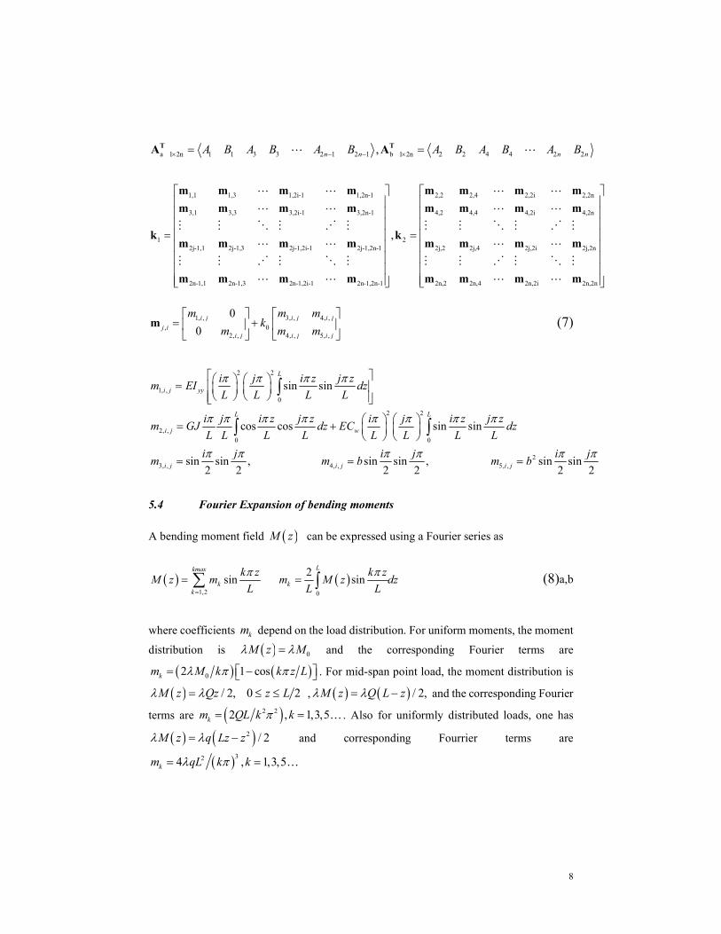
5.4 Fourier Expansion of bending moments
A bending moment field M z can be expressed using a Fourier series as
1,2 0
2sin sin
Lkmax
k kk
k z k zM z m m M z dz
L L L
(8)a,b
where coefficients km depend on the load distribution. For uniform moments, the moment
distribution is 0M z M and the corresponding Fourier terms are
02 1 coskm M k k z L . For mid-span point load, the moment distribution is
/ 2, 0 2 M z Qz z L , / 2,M z Q L z and the corresponding Fourier
terms are 2 22 , 1,3,5km QL k k . Also for uniformly distributed loads, one has
2 / 2q L zM zz and corresponding Fourrier terms are
324 , 1,3,5km qL k k

9
5.5 Destabilizing term due to bending moments
From Eqs.(4), (5) and (8)a, by substituting into Eq. (3)a, and performing integrals, the load potential energy gain can be expressed as
T
ag1 g12T T1 a b T
bg12 g22V
Ak kA A
Ak k (9)
where
1,1 1,3 1,2i-1 1,2n-1 2,2 2,4 2,2i 2,2n
3,1 3,3 3,2i-1 3,2n-1 4,2 4,4 4,2i 4,2
2j-1,1 2j-1,3 2j-1,2i-1 2j-1,2n-1
2n-1,1 2n-1,3 2n-1,2i-1 2n-1,2n-1
,
g1 g2
n n n n n n n n
n n n n n n n n
k kn n n n
n n n n
n
2j,2 2j,4 2j,2i 2j,2n
2n,2 2n,4 2n,2i 2n,2n
1,2 1,4 1,2i 1,2n
3,2 3,4 3,2i 3,2n
2j-1,2 2j-1,4 2j-1,2i 2j-1,2n
2n-1,2 2n-1.4 2n-1,2i 2n-1,
g12
n n n n
n n n n
n n n n
n n n n
Kn n n n
n n n n
6, ,
7, ,
2n
0,
0i j
i j
m
m
j,in
(10)a-d
in which, one has
2 2
6, , 7, ,( , , ), ( , )i j max i j max
j im L j i k m L i, j k
L L
(11)
1,20
1( , , )= sin sin sin
L kmax
max kk
i z j z k zi j k m dz
L L L L
(12)
5.6 Special considerations for symmetric loading
For symmetric loading with respect to 2z L and symmetric boundary conditions, the
moments are symmetric and Eq. (8)a can be shown to take the form

10
1,3,5
sinkmax
kk
k zM z m
L
(13)
in which the summation in Eq.(13) is only on the odd terms 1,3,5..k Thus, when either one of ,i j is odd and the other is even, matrix j,in in Eq. (10)d can be shown to vanish.
This is the case since function sin sini z L j z L is anti-symmetric with respect to
2z L and the summation 1,2
sin sin sinmaxk
kkm i z L j z L k z L
arising in Eq.
(12) is also anti-symmetric. Hence
max
1,20( , , )= 1 sin sin sin 0
L k
max kki j k L m i z L j z L k z L dz
. By substituting
into Eq. (11), one has ,j i n 0 , g12k = 0 , and Eq. (9) simplifies to
g1 aT T
1 a bg2 b2
V
k 0 AA A
0 k A (14)
5.7 Destabilizing terms due to load height effect
5.7.1 Case1-Mid-span load
The loading function corresponding to a mid-span point load Q is
/ 2q z Q z L in which the Dirac Delta function. By substitution into Eq. (3)
b, and expressing the result in a matrix form, one obtains
2 ag3 g34T T2 a b T
bg34 g402 2 2
L LV Q z a z dz
Ak k= A A
Ak k (15)
where

11
1,1 1,3 1,2i-1 1,2n-1 2,2 2,4 2,2i 2,2n
3,1 3,3 3,2i-1 3,2n-1 4,2 4,4 4,2i
g3 g42j-1,1 2j-1,3 2j-1,2i-1 2j-1,2n-1
2n-1,1 2n-1,3 2n-1,2i-1 2n-1,2n-1
,Qa Qa
r r r r r r r r
r r r r r r r
k kr r r r
r r r r
4,2n
2j,2 2j,4 2j,2i 2j,2n
2n,2 2n,4 2n,2i 2n,2n
1,2 1,4 1,2i 1,2n
3,2 3,4 3,2i 3,2n
g342j-1,2 2j-1,4 2j-1,2i 2j-1,2n
2n-1,2 2n-1.4 2n-1,2i
Qa
r
r r r r
r r r r
r r r r
r r r r
kr r r r
r r r
j,i
2n-1,2n
0 0
,0 sin sin
2 2
i j
r
r
(16)
when either of i , j are even and the other is odd, the expression sin 2 sin 2i j
vanishes and hence matrix 34gk vanishes. The load potential energy 2V takes the form
g3 aT T2 a b
g4 b(1)2
V
k 0 A= A A
0 k A (17)
where subscript (1) denotes Case 1.
5.7.2 Case2- Distributed load
The load potential gain induced by the load height can be expressed as
2 22
21,2 1,20 0
g3 aT Ta b
g4 b(2)
sin sin2 2
2
L L n n
i ji j
i z j zV qa z dz qa B B dz
L L
k 0 A
A A0 k A
(18)
where subscript (2) denotes Case 2 and
g3 g4
10,1,0,1...0,1
2qLa k k Diag (19)

12
5.8 Stationarity conditions
From Eqs. (6), (9), (17) and (18), by substituting into the total potential energy U V , and evoking the stationarity conditions a b A A 0 , one obtains
g1 g3 a1
g2 g42
0 b
k 0 k 0 Ak 0
0 k 0 k A0 k (20)
The two partitions of Eq. (20) can be expanded into two separate eigenvalue problems
1 1 g1 g3 a 0 k k k A (21)
2 2 g2 g4 b 0 k k k A (22)
Eqs. (21) and (22) are solved yielding two groups of eigenvalues 1 and 2 . The buckling
mode of interest is the one corresponding to the smallest eigenvalue. The entries of vector
aA always correspond to a symmetric buckling mode while those of vector bA correspond
to an anti-symmetric mode (Hu 2016).
5.9 Recovering the threshold bracing stiffness
As shown in the results (e.g., Fig. 8), while the critical load corresponding to Mode 1 (symmetric) depends on the lateral bracing stiffness, that based on Mode 2 (anti-symmetric) is found to be independent of the bracing stiffness, yielding a constant critical moment value for a given beam geometry and load configuration. In contrast, the buckling moment corresponding to Mode 1 decreases as the bracing stiffness decreases. Conceptually, there is a threshold bracing stiffness crk at which both modes yield equal critical moments. The
concept of threshold bracing stiffness has also been discussed in Mutton and Trahair (1973), Tong and Cheng (1988) and Yura (2001). When the lateral bracing stiffness is above the threshold stiffness, the member attains its maximal capacity as dictated by the anti-symmetric mode. The present section develops a methodology to directly recover the critical bracing stiffness. Eq. (22) is first solved for the eigenvalue 2 , and one sets 1 2 .
Eq. (21) is then solved for the threshold bracing stiffness. From Eqs. (7), the elastic stiffness matrix 1k can be expressed as the sum of two matrices as
1 11 crk k k k (23)
where

13
1,1 1,3 1,2i-1 1,2n-1
3,1 3,3 3,2i-1 3,2n-1
1
2j-1,1 2j-1,3 2j-1,2i-1 2j-1,2n-1
2n-1,1 2n-1,3 2n-1,2i-1 2n-1,2n-1
m m m m
m m m m
km m m m
m m m m
, 1, ,
2, ,
0
0i j
j ii j
m
m
,m
1,1 1,3 1,2i-1 1,2n-1
3,1 3,3 3,2i-1 3,2n-1
1
2j-1,1 2j-1,3 2j-1,2i-1 2j-1,2n-1
2n-1,1 2n-1,3 2n-1,2i-1 2n-1,2n-1
m m m m
m m m m
km m m m
m m m m
, 3, , 4, ,
,4, , 5, ,
i j i j
j ii j i j
m m
m m
m
(24)
From Eq. (23), (24), by substituting into Eq.(21), one obtains a linear eigenvalue problem in the eigen-pairs ( crk , aA ) of the form
1 12 g1 2 g3 acrk k k k k A 0 (25)
Given matrices 1 2 g1 2 g3 k k k and 1k , Eq. (25) can be solved for the eigen-pair ( crk ,
aA ) to yield the critical stiffness. It is emphasized that, unlike standard buckling solvers
where the analyst would have to solve the buckling problem multiple times for various values of the bracing stiffness for a given problem and determine the critical stiffness by trial and error, Eq. 25 determines the critical stiffness in a single step. This feature is key in developing the large database of runs discussed in Section 7.
6. Verification
To determine the number of Fourier terms n needed for convergence, a convergence study was conducted on 32 cases with different load configurations (uniformly distributed, mid-span point loads), brace heights, load heights and elastic restraint stiffness (Hu 2016). The ratio of critical moments based on 4n were compared to those based on 6n with a difference of 0.2% or less in all 32 cases considered. It is concluded that 4n is enough to achieve convergence. Given that the computational run time involved is nearly instantaneous, the number of modes n was conservatively set to 9, (i.e., 18 Fourier terms were taken in Eqs. (4)) in all subsequent analyses.

14
6.1 Comparison with finite element analysis
To assess the validity of predictions of the present solution, a series of problems were solved and the results were compared to those based on 3D FEA eigenvalue buckling analyses based on the commercial software ABAQUS. The reference problem chosen for comparison is a wood beam with a width 130w mm , height 950h mm , and span
13, 000L mm . Section properties are 3 8 4/12 1.74 10yyI hw mm , 3 3 13 6144 1.31 10wC w h mm . and 8 46.36 10J mm (based on Pai 2007). Beam
material is assumed to be glued-laminated timber, Spruce-Lodgepole Pine with 20f-EX grade with 10,300LE E MPa (CSA O86 2014) and 474LT LRG G G MPa
(FPL 2010). The selection of the reference beam was based on the following considerations: 1) the cross-section size is taken from the selections tables in the Wood Design Manual (2015) and is readily available in the Canadian market, 2) the beam span was selected so that its resistance is governed by the elastic lateral torsional buckling mode according to CAN-CSA-O86-2014 provisions, 3) the depth-to-width aspect ratio are with ranges recommended by APA (2013), and 4) the beam meets deflection criteria of CAN-CSA-O86-2014. Two values for the bracing stiffness are taken for verification; 310 kN m and
410 kN m . It is noted that a proper quantification of the stiffness of a bracing system
depends on several factors including the flexibilities of (a) the brace, (b) the connection between the brace and the beam, (c) the supporting structure at the other end of the brace, and (d) the connection between the brace and the supporting structure at the other brace. The stiffness of the system could be determined either by testing or by detailed modelling of the structural system surrounding the beam and is outside the scope of the present study. In the present section, two bracing stiffness values ( 310 kN m and 410 kN m ) were
selected for the purpose of verifying the model. In the parametric study in Section 8, a wider range of bracing stiffness values will be examined and Section 9 will provide the critical brace stiffness against which the bracing stiffness of the system is to be compared.
The beam was modelled using the C3D8 brick element in ABAQUS (Simulia, 2011). The C3D8 element is a three-dimensional continuum element with 8 nodes and three translational degrees of freedom per node, totaling 24 degrees of freedom. The element adopts linear interpolation for the displacement fields. An orthotropic material model is adopted to represent the wood properties. Additional material properties needed for ABAQUS input were taken from FPL (2010): Young Modulus in the tangential and radial directions 700T RE E MPa , shear modulus 51.5RTG MPa , Poisson’s ratios
0.347LR LT ; and 0.469RT . Two groups of restraints were enforced at both ends
of the model to simulate the simply supported conditions (Fig. 3): (1) A set of constraints related to vertical displacements were imposed along axes A B and A B at the end cross sections. For axes CD and C D , the lateral displacements were restrained by imposing another group of constraints. (2) The centre of the cross section at one end was longitudinally restrained (Fig. 3a), while the other end was left free to move longitudinally (Fig. 3b). A mid-span lateral brace was simulated by adding a SPRING1 element located at the central vertical axis of the mid-span section. The SPRING1 element is used to model springs between a given node and the ground, along a specified direction (horizontal in the

15
present problem). A mesh sensitivity analysis was conducted on 8 cases with different load configurations (uniformly distributed load, mid-span point load) and various values of lateral bracing stiffness. The governing buckling modes were symmetric in some of the runs and anti-symmetric in the other runs. The results (Hu 2016) showed that critical moment predictions based on 410 elements longitudinally, 50 elements along the height, and 10 elements along the width, do not change by more than 0.04% when finer meshes are taken. Thus, a 410x50x10 mesh was taken in subsequent verification runs.
Fig. 3 Boundary conditions (all arrows denote restrained degrees of freedoms) (a) left end (b) right end
A comparison of the predicted buckling load versus the normalized bracing height ( / )b h
for the reference case is provided in Fig. 4. The buckling loads based on the present solution are found to agree within 0.57%-4.27% with the ABAQUS solutions (Hu 2016). Critical loads based on the present study are slightly higher than those based on the ABAQUS simulations since the assumptions underlying the present model neglect distortional and transverse shear deformation effects. As a result, the present solution provides a slightly stiffer representation of the beam than does the ABAQUS model which captures both effects. Four groups of runs were conducted, in which the loading type (concentrated, uniformly distributed) and the load height a (top face, mid-height) were varied. Both models predict two types of buckling modes: symmetric and anti-symmetric. The anti-symmetric mode is associated with a critical moment magnitude that is independent of the bracing height since the mid-span angle of twist 2L and lateral deflection 2u L
vanish and so is the lateral displacement at the spring ( / 2, ) 2 2 0spu L b u L b L
as evident by Eq. 5. Hence, the internal strain energy 2
2 01 2 / 2spU k u L stored in the
spring vanishes, as evident by Eq. 2b. The corresponding total potential energy term is no longer dependent on the bracing height in such a case. In contrast, the critical moments based on the symmetric mode are found to increase with the bracing height under point loads (Figs. 4a, b). For uniformly distributed loading, a similar trend is observed up to a certain brace height (Figs. 4c, d) after which the critical moment based on the symmetric mode remain nearly constant. Representative mode shapes for the uniformly distributed

16
load case with𝑎 = 0 , 𝑘 = 10 𝑘𝑁 𝑚⁄ are illustrated in Fig. 5. Shown are the lateral displacements plots along the beam length for / 2u h , u , and / 2u h , at the top face, the centroid, and the bottom face, respectively. The mode shapes in Figs. 5a, b correspond to the case b/h= - 0.3 and are representative of the symmetric and anti-symmetric modes, respectively. As previously observed in Figs. 4c, d, the symmetric mode critical moments for uniformly distributed loads exhibit a sharp kink when b/h attains about 0.1 and 0.2, respectively, after which it reaches a nearly flat plateau. The observed kinks correspond to a change in the shape of the symmetric mode from the typical mode depicted in Fig. 5(b) to that in Fig. 5c (based on b/h =0.2). Further increase in the bracing height ratio to b/h =0.4 is found to influence the buckling mode only very mildly as evident by the modes in Figs. 5c and d. Hence, the critical load of 39.15kN for b/h=0.2 barely changes to 39.25kN for b/h=0.4. Figure 6 provides a comparison between the buckling mode shapes based on the present solution and that based on ABAQUS for point load and uniformly distributed loads, for the symmetric and anti-symmetric modes, and for a variety of bracing heights. Close agreement is observed between both models. Similar agreement between mode shapes is observed for other loading and bracing height combinations (Hu 2016).
(a)
(b)
(c)
(d)
Present study-symmetric-n=9 Present study-antisymmetric-n=9
ABAQUS-symmetric ABAQUS-antisymmetric

17
Fig. 4 Buckling load of reference case for (a) Point load, 𝑎 = 0, 𝑘 = 10 𝑘𝑁 𝑚⁄ , (b) point load, 𝑎 = 0.5ℎ, 𝑘 = 10 𝑘𝑁 𝑚⁄ , (c) uniformly distributed load, 𝑎 = 0, 𝑘 = 10 𝑘𝑁 𝑚⁄ , and (d) uniformly distributed load, ,
𝑎 = 0.5ℎ, 𝑘 = 10 𝑘𝑁 𝑚⁄
(a)
(b)
(c)
(d)
bottom face displacement; bottom face displacement; top face displacement;
Figure. 5 Mode shapes for uniformly distributed loading with load height 𝑎 = 0 and lateral bracing stiffness 𝑘 = 10 𝑘𝑁 𝑚⁄ for (a) b/h= - 0.3 - symmetric mode, (b) b/h = - 0.3 - anti-symmetric mode, (c) b/h =0.2, - symmetric mode, and (d) b/h =0.4 - symmetric mode

18
(a)
(b)
(c)
(d)
(e)
(f)
(g)
(h)

19
Fig. 6 Lateral displacement diagrams for buckling mode shape for beams subject to mid-span point load (a-d) and uniformly distributed loads (e-h)- (a) Symmetric mode, 𝑎 = 0, b=0, 𝑘 = 10 𝑘𝑁 𝑚⁄ (b) Anti-symmetric mode, 𝑎 = 0, b=0, 𝑘 = 10 𝑘𝑁 𝑚⁄ (c) Symmetric mode, 𝑎 = 0, b=0.5h, 𝑘 = 10 𝑘𝑁 𝑚⁄ (d) Anti-symmetric
mode , 𝑎 = 0, b=0.5h, 𝑘 = 10 𝑘𝑁 𝑚⁄ (e) Uniformly distributed load, symmetric mode, 𝑎 = 0, b=0, 𝑘 =10 𝑘𝑁 𝑚⁄ (f) Uniformly distributed load, anti-symmetric mode, a = 0, b=0, 𝑘 = 10 𝑘𝑁 𝑚⁄ , (g) Uniformly distributed load, symmetric mode, , 𝑎 = 0, b=0.5h, 𝑘 = 10 𝑘𝑁 𝑚⁄ and (h) Uniformly distributed load, anti-
symmetric mode, , 𝑎 = 0, b=0.5h, 𝑘 = 10 𝑘𝑁 𝑚⁄
6.2 Comparison with previous research
Schmidt (1965) developed a lateral torsional buckling solution for beams with rectangular sections subjected to a point load at mid-span. The model involved two elastic torsional restraints at both ends and an elastic lateral restraint at mid-span. Unlike the present study, the solution in Schmidt (1965) neglects warping and assumes that the bracing height coincides with the load height. A comparison between the present model predictions and those based on the Schmidt solution is provided in Fig. 7 for 3 48 5,10, and 40yykL EI .
In the solution by Schmidt (1965), the stiffness of the end torsional restraints was set to infinity to emulate the end conditions 0 0L . The lateral torsional buckling
capacity based on the present study is observed to be slightly higher than that based on Schmidt (1965). The difference is attributed to the warping effect which is captured only in the present study. Excellent agreement is obtained between both solutions when the warping contribution was omitted in the present study, as evidenced by the nearly overlapping plots in Fig. 7.
McCann (2013) developed a solution for the buckling moment and threshold stiffness crk
for simply supported beams subjected to uniform moments, with a number of equidistant intermediate eccentric lateral braces. The solution of McCann (2013) is used to assess the validity of the present model by setting to one the number of lateral restraints. Results are
shown in Fig. 8, where yy wb I C is a non-dimensional brace height, cr is the
normalized brace height required to achieve the full bracing condition, and ,cr aM is the
critical moment based on the anti-symmetric mode. The buckling load predictions based on the present study are in very good agreement with those based on McCann (2013), both for the symmetric and anti-symmetric modes, for various bracing heights and elastic stiffness values.

20
(a)
(b)
(c)
Schmidt –symmetric;
Schmidt -anti-symmetric;
Present study –symmetric;
Present study -anti symmetric;
Present study -symmetric (no warping);
Present study anti-symmetric (no warping);
Fig. 7 Critical load predictions of present model versus Schmidt solution for (a) 𝑘𝐿 48𝐸𝐼 = 5 (b) 𝑘𝐿 48𝐸𝐼 = 10 and (c) 𝑘𝐿 48𝐸𝐼 = 40

21
Fig. 8 Comparison of results based on present solution and McCann solution for single mid-span lateral brace
7. Parametric study
While the present formulation is valid for general doubly symmetric cross-sections, the present parametric study places emphasis on wooden beams with rectangular cross-section given their common use in practice. The effect of bracing stiffness on the elastic critical moment is investigated by varying the bracing stiffness from 10kN m to 610 kN m for
the reference case described Section 6. The results (Fig. 9) reveal that the buckling load corresponding to the anti-symmetric mode is independent of the lateral bracing stiffness. In contrast, for the symmetric mode, the critical load decreases with the lateral bracing stiffness. For the case where bracing is located at the section centroid or at the top face, the critical moments based on the symmetric mode can attain those based on the anti-symmetric mode when the bracing stiffness attains a threshold value. In contrast, for bracing at the bottom face, the critical moments based on the symmetric mode are found to be always smaller those based on the anti-symmetric mode, irrespective of the bracing stiffness magnitude.

22
(a)
(b)
brace at centroid (b = 0) Symmetric brace at centroid (b =0) Anti-symmetric brace at top (b = 0.5h) Symmetric brace at top (b = 0.5h) Anti-symmetric
brace at bottom (b = -0.5h) Symmetric brace at bottom (b = -0.5h) Anti-symmetric
Fig. 9 Critical moment versus normalized brace stiffness for (a) point load (b) uniformly distributed load
8. Simplified expressions for threshold bracing stiffness
For design purposes, it is desirable to determine the lateral brace stiffness required to maximize the critical moment. The objective of this section is to develop a simplified
expression for estimating such a critical brace stiffness crk . In a dimensionless form, the
critical brace stiffness 3cr yyk L EI depends on five parameters, i.e.
30 , , , ,cr yyk L EI f w h a h b h L h G E . To reduce the parameters involved to a
manageable number, the simplified solution sought will focus on the common case where the point of load application provides a lateral restraint, i.e., a b . In such a case, one has
31 , , ,cr yyk L EI f w h b h L h G E . Two reference cases have been defined in the
present analysis. For both cases, the section width is taken as 130w mm , the height is950h mm , the modulus of elasticity is 10300LE MPa and the shear modulus is
644G MPa . The spans of the two reference cases are 10m and 15m, both of which correspond to an elastic lateral torsional buckling mode of failure according to CAN-CSA-O86-2014.
8.1 Sensitivity analysis
The four parameters , , ,w h b h L h G E were varied in the practical range of values, i.e.,
0.137 0.570, 0.5 0.5,5.263 21.053w h b h L h and 0.0500 0.100G E
which cover the elastic lateral torsional buckling and inelastic lateral torsional buckling modes of failure according to CSA O86 (2014). A database of 434 runs (Hu 2016) was developed within the ranges specified. For each run, the threshold stiffness crk was
determined from the eigenvalue problem defined in Eq. (25).

23
Of the 434 cases investigated, 44 runs were conducted to assess the effect of G E . As
G E was increased from 0.05 to 0.1 , the normalized threshold bracing stiffness
3crk EI L was observed to decrease only by 7.15% (Fig. 10a). Another 44 runs where
the cross-section aspect ratio w h was varied from 0.137 to 0.570, showed that the
normalized threshold bracing stiffness 3crk EI L varied only within 4.47% (Fig. 10b).
Both sets of results suggest that G E and w h have a negligible effect on the normalized
threshold bracing stiffness. The span to depth ratio L h was then varied from 5.26 to 21.1.
The results (Figure 10c) show a pronounced effect of L h on the normalized threshold
bracing stiffness 3crk EI L as the percentage difference between the smallest and largest
values of 3crk EI L is 32.7%. Lastly, the load height to section depth ratio /b h was
varied from -0.5 to 0.5. The results (Fig. 10d) indicate that the effect b h is rather
pronounced on the normalized threshold bracing stiffness. In summary, the above sensitivity analysis suggests that the normalized threshold bracing stiffness can be reasonably approximated as a function of two key parameters, i.e.
33 ,cr yyk EI L f L h b h (26)
(a)
(b)

24
(c)
(d)
Fig. 10 Sensitivity analysis for normalized threshold stiffness for point load and uniformly distributed load (a) effect of shear to elastic moduli 𝐺 𝐸⁄ , (b) effect of aspect ratio 𝑤 ℎ⁄ , (c) effect of span to depth ratio 𝐿 ℎ⁄ , and (d) effect of load height to section depth ratio 𝑏 ℎ⁄
8.2 Regression analysis
A single regression equation of the form ,Z f X Y where 3log cr yyZ k L EI ,
X L h and Y b h was originally sought and was found unattainable. Thus, 11
separate regression equations of the form iYZ X were developed for the cases
0.5....0,....0.5iY :
max
max
max0 10
...i
jj j
Y i i j i jij
Z a a X a X a X
(27)
where maxj is the number of terms needed to fit the results obtained from the parametric
runs (Hu 2016) and jia are coefficients determined from the regression analysis. The sum
of the squares of the differences between the values of YiZ based on the present eigenvalue solution and that based on the approximation sought in Eq. (27) is minimized, i.e.,
max
2max
1 0
i m njk
jYii ji
k j
D Z a X
(28)
in which maxk is the number of runs conducted. By enforcing the conditions 0i jiD a
the regression constants were determined. The results are depicted in Fig. 11 and the corresponding regression constants are provided in Table 1 both for uniformly distributed

25
and point loading. For load height ratios 0.1,0.2, 0.5a h , excellent fits were obtained
by setting the order of regression polynomial to max 2j . For beams with
0.1, 0.2, 0.5a h , more terms were found necessary and maxj was set equal to 5
for point loading and to 4 for uniformly distributed loading. For a h values lying between
iY and 1iY , linear interpolation can be used to determine 3log cr yyZ k L EI . For the cases
of short span to height ratios L/h and cross-section aspect ratios b h = -0.3,-0.4, and-0.5
a small reduction in L/h is associated with a large increase in threshold stiffness as shown in Figs. 11(b, d).
(a)
(b)
(c)
(d)
results from present study Regression fitting curves
Fig. 11 Threshold bracing stiffness versus span to height ratio for (a) point load above mid-height (b) point load below mid-height (c) uniformly distributed load above mid-height (d) uniformly distributed load below mid-
height

26
Table 1. Regression coefficients of simplified design equations
Point load
i
a h 0 1 2 3 4 5 *R
-0.5 123.8 -36.40 4.39 -2.64E-01 7.89E-03 -9.37E-05 1.000
-0.4 74.17 -23.45 3.08 -2.00E-01 6.41E-03 -8.12E-05 0.998
-0.3 35.00 -11.26 1.57 -1.08E-01 3.65E-03 -4.84E-05 0.996
-0.2 17.05 -5.30 7.90E-01 -5.72E-02 2.03E-03 -2.81E-05 0.996
-0.1 5.09 -7.20E-01 9.50E-02 -6.38E-03 2.14E-04 -2.80E-06 1.000
0.0 3.00 -3.48E-02 9.95E-04 - - - 0.980
0.1 2.74 -1.07E-02 3.43E-04 - - - 0.944
0.2 2.55 4.29E-03 -4.22E-05 - - - 0.997
0.3 2.42 0.46E-02 -2.93E-04 - - - 1.000
0.4 2.30 2.20E-02 -4.67E-04 - - - 1.000
0.5 2.21 2.76E-02 -5.93E-04 - - - 0.999
Uniformly distributed load
-0.5 40.22 -8.33 7.00E-01 -2.64E-02 3.73E-04 - 1.000
-0.4 18.38 -3.64 3.20E-01 -1.27E-02 1.89E-04 - 0.999
-0.3 10.02 -1.81 1.69E-01 -7.07E-03 1.10E-04 - 0.999
-0.2 6.37 -1.00 1.01E-01 -4.49E-03 7.40E-05 - 0.997
-0.1 3.68 -2.80E-01 2.57E-02 -1.08E-03 1.71E-05 - 1.000
0.0 2.65 -3.10E-02 8.72E-04 - - - 0.984
0.1 2.42 -1.16E-02 3.67E-04 - - - 0.954
0.2 2.26 9.06E-04 5.72E-05 - - - 0.989
0.3 2.13 9.78E-03 -1.55E-04 - - - 1.000
0.4 2.02 1.65E-02 -3.12E-04 - - - 1.000
0.5 1.93 2.19E-02 -4.35E-04 - - - 1.000

27
8.3 Assessing errors in critical moment predictions induced by interpolation
To assess the effect of the approximation introduced by interpolation where b h lies
between iY and 1iY , the critical moments based on the threshold stiffness predicted by the
present model are compared to those based on interpolation for four cases involving point load and uniformly distributed load and various /L h and /b h ratios (Table 2). In all four cases, the difference between critical moment predictions based on both methods is found to be less than 0.5%, suggesting the validity of the interpolation solution.
Table 2. Comparison of critical moments as determined based on the present model and interpolation between the simplified regression equations
Load type b h L h Critical moment based on present
model (kNm)
Critical moment based on
interpolation (kNm) difference
point load -0.25 10 1093 1087 0.50%
0.35 11 980.6 980.3 0.03%
uniformly distributed
load
-0.15 12 666.8 666.8 0.00%
0.25 13 580.4 580.4 0.00%
8.4 Threshold stiffness outside the range of investigation
As shown in Figs. 10(b,d), for the cases of bottom loading a h b h = -0.3,-0.4,-0.5, the
threshold bracing stiffness can reach very large magnitudes. In the absence of information within this range in Fig. 10, the designer may opt to adopt the largest value available. It is of interest to assess the error on the critical moment prediction induced by such an approximation. Six cases with different loading, 𝑏 ℎ⁄ , and 𝐿 ℎ⁄ were investigated. The results in Table 3 show a large difference between the peak critical bracing stiffness depicted from Fig.11 and that based on the eigenvalue solution. For example, for run 6, the critical bracing stiffness based on the eigenvalue solution is 183x103𝑘𝑁 𝑚⁄ . This value is significantly higher compared to the peak stiffness of 51.8 x10³ 𝑘𝑁 𝑚⁄ based on Fig. 10. Nevertheless, the corresponding difference in critical moments based on both values is a mere 3.17%. For all six cases considered, adopting the highest critical stiffness on Fig. 10 are found to introduce an error of no more than 5.87%.

28
Table 3.Comparison of threshold bracing as determined by the present eigenvalue solution and approximate regression equations
Threshold bracing
stiffness (10 𝑘𝑁 𝑚⁄ )
Critical Moment (10 𝑘𝑁𝑚)
based on detailed solution
(1)
𝑏 ℎ⁄
(2)
𝐿 ℎ⁄
(3) Based on detailed
solution (𝑘 )
(4) Maximum 𝑘 based on Figs. 10b,d
(5)
Based on
𝑘
(6)
Based on
𝑘
Difference
((5)-(6))/(5)
(%)
Point load
1 -0.3 6.84 201 98.6 1.72 1.71 0.64
2 -0.4 8.53 132 41.3 1.32 1.30 0.96
3 -0.5 10.32 453 21.4 1.05 1.05 0.75
Uniformly distributed load
4 -0.3 6.84 380 12.6 1.34 1.26 5.87
5 -0.4 8.95 225 73.8 9.76 0.94 4.14
6 -0.5 11.05 183 51.8 0.77 0.75 3.17
9. Summary and Conclusions
An analytical solution was developed for the prediction of lateral torsional buckling capacity of simply supported wooden beams with discrete elastic lateral restraints at mid-span subjected to symmetric loads relative to mid-span.
The validity of the model was established through comparisons with ABAQUS results and published results by Schmidt (1965) and McCann (2013).
Depending on the load and bracing heights and elastic restrain magnitude, two possible lateral torsional buckling modes were observed; symmetric and antisymmetric.
A technique was developed to directly recover the threshold stiffness required to suppress the symmetric mode and maximize the critical moment of the beam. The technique involves solving an eigenvalue problem in the bracing stiffness and eliminates the need for trial and error required in standard buckling solutions.

29
Critical moments based on the symmetric mode were observed to decrease with a decrease in bracing height, while those based on the anti-symmetric mode remain independent of the mid-span bracing height.
For relatively weak bracing stiffness, the symmetric mode tends to govern the buckling capacity of the beam while for relatively stiff bracing, the anti-symmetric mode tends to govern the buckling capacity of the beam.
Critical moments based on the symmetric modes decrease when the load height increases for both loading types investigated; point load and uniformly distributed. For mid-span point loading, critical moments based on the anti-symmetric mode are found independent of the load height and bracing stiffness. Conversely, for uniformly distributed loads, critical moments based on the anti-symmetric mode are observed to decrease as the point of application of the load moves upwards.
In most cases, for a given load height and bracing height, a threshold bracing stiffness was found to exist. Above this threshold value, the critical moment is dictated by the anti-symmetric critical moment while below the threshold stiffness value, it is dictated by the symmetric mode, which corresponds to a smaller critical moment.
For the common case where the point of load application coincides with the bracing height, simplified equations have been developed to determine the threshold bracing stiffness required to attain the critical moment based on the anti-symmetric mode.
10. Notation
The following symbols are used in this paper:
a = load height from cross-section centroid;
b = bracing height from cross-section centroid;
wC = warping constant;
E = Young’s modulus of wooden beam along the longitudinal direction;
G = shear modulus of the beam;
h = cross section height;
yyI = weak moment of inertia;
J = Saint-Venant torsional constant;

30
crk = threshold stiffness from as obtained from eigenvalue analysis;
crk = approximate threshold bracing stiffness;
0k = spring constant reflecting the lateral bracing stiffness;
L = beam span;
,cr aM = critical moment based on the anti-symmetric mode;
km = Fourier coefficient;
n = number of Fourier terms;
crP = critical load;
Q = reference point load;
q = reference uniformly distributed load;
u = lateral displacement at section centroidal axis:
spu = lateral deformation at the lateral bracing location;
U = internal strain energy of the beam-spring system;
V = load potential energy gain of the system;
w = cross section width;
crw = critical load;
= normalized brace height relative to cross-section shear centre;
cr = normalized threshold bracing height relative to cross-section centre;
= twisting angle;
= load multiplier;

31
= Poisson’s ratio;
= total potential energy of the system.
11. Acknowledgments
The authors gratefully acknowledge funding from the Natural Sciences and Engineering Research Council (NSERC) of Canada to the second and third authors.
12. References
Andrade, A., and Camotim, D, Lateral-torsional buckling of singly symmetric tapered beams: theory and applications, J. Eng. Mech., 131(6) (2005) 586-597
Andrade, A., Camotim, D. Dinis, P.B, Lateral-torsional buckling of singly symmetric web-tapered thin-walled I-beams: 1D model vs. shell FEA, Comput. Struct., 85(17-18) (2007) 1343-1359
American Forest and Paper Association (AFPA), Technical Report 14: Designing for lateral torsional stability in wood members, Washington, D.C., U.S. (2003)
American Wood Council (AWC), National design specification for wood construction, ANSI/AWC NDS-2015, Virginia, U.S. (2015).
APA (2013), Allowable Depth-to-Width Ratios for Glulam Beams, Technical Topic TT-085B, Tacoma, Washington, USA
Canadian Standard Association (CSA). Engineering design in wood, O86-14, Mississauga, Ontario, Canada (2014).
Du, Y., Mohareb, M., and Doudak, G., Nonsway Model for Lateral Torsional Buckling of Wooden Beams under Wind Uplift, Journal of Engineering Mechanics, DOI: 10.1061/(ASCE)EM.1943-7889.0001172 (2016a)
Du, Y., Mohareb, M., and Doudak, G. Lateral Torsional Buckling of Twin-beam deck assemblies under wind uplift–sway versus non-sway models, World conference in timber engineering, Vienna Austria, Aug. 22-25 (2016b)
Erkmen, R.E. and Mohareb, M., Buckling analysis of thin-walled open members-A finite element formulation, Thin. Wall. Struct., 46(6) (2008) 618-636.
Flint, A.R. (1951), The influence of restraints on the stability of beams, Struct. Eng., 29(9) (1951) 235-246.

32
Forest Products Laboratory (FPL) Wood handbook-Wood as an engineering material, Wisconsin, U.S. (2010).
Helwig, T., Frank, K., Yura, J, Lateral-torsional buckling of singly symmetric I-beams, J. Struct. Eng., 123(9) (1997) 1172-1179.
Hołubowski R. and Jarczewska K., Lateral-torsional buckling of non-uniformly loaded beam using differential transformation method, International Journal of Structural Stability and Dynamics, 16(7) (2016), DOI: 10.1142/S0219455415500340
Hu, Y., Lateral torsional buckling of wooden beams with mid-span lateral bracing, Master Thesis, Department of Civil Engineering, University of Ottawa, Ottawa, ON. (2016)
Ings, N.L. and Trahair, N.S, Beam and column buckling under directed loading, J. Eng. Mech., 113(6) (1987) 1251-1263.
Jingping, L., Zaitian, G. Chen, S, Buckling of transversely loaded I-Beam columns, J. Struct. Eng., 114(9) (1988) 2109-2118.
Kerensky, O.A., Flint, A.R., Brown, W.C, The basis for design of beams and plate girders in the revised British Standard 153, P. I. Civil. Eng., 5(3) (1956) 396–461.
Kitipomchai, S., Dux, P.F., Richter, N.J, Buckling and bracing of cantilevers.” J. Struct. Eng., 110(9) (1984) 2250-2262.
Lay, M.G., Galambos, T.V., Schmidt, L.C, Lateral bracing force of steel I beams, J. Eng. Mech. Div., 89(EM3) (1963) 217-224
Lamb, A.W., and Eamon, C.D., Load height and moment factors for doubly symmetric wide flange beams, J. Struct. Eng., 10.1061/(ASCE)ST.1943-541X.0001332, 04015069 (2015).
Mutton, B.R., and Trahair, N.S., Stiffness requirement for lateral bracing, J. Struct. Eng. Div., 99(10) (1973) 2167-2182
Mohri, F., and Potier-Ferry, M., Effects of load height application and pre-buckling deflection on lateral buckling of thin-walled beams, Steel. Compos. Struct;, 6(5) (2006) 1-15
Mohebkhah A, Lateral buckling resistance of inelastic I-beams under off-shear center loading, Thin. Wall. Struct., 49(3) (2010) 431-436
McCann, F., Wadee, M.A., Gardner, L., Lateral stability of imperfect discretely braced steel beams, J. Eng. Mech., 139(10) (2013) 1341-1349

33
Nethercot, D.A., and Rockey, K.C., A unified approach to the elastic lateral buckling of beams Struct. Eng., 49(7) (1971) 321-330
Nethercot, D.A., and Rockey, K.C., The lateral buckling of beams having discrete intermediate restraints, Struct. Eng., 50(10) (1972) 391-403
Pi, Y.L., Traihair, N.S., Rajasekaran, S., Energy equation for beam lateral buckling, J. Struct. Eng., 118(6) (1992) 1462-1479
Samanta, A., and Kumar, A., Distortional buckling in monosymmetric I-beams, Thin. Wall. Struct., 44(1) (2006) 51-56
Sahraei, A., Wu, L., Mohareb, M., Finite element formulation for lateral torsional buckling analysis of shear deformable mono-symmetric thin-walled members, Thin. Wall. Struct., doi:10.1016/j.tws.2014.11.023 (2015).
Sahraei, A. and Mohareb, M., Upper and lower bound solutions for lateral-torsional buckling of doubly symmetric members, Thin. Wall. Struct., doi:10.1016/j.tws.2016.01.015 0263-8231 (2016).
Schmidt, L.C., Restraints against elastic lateral buckling.” J. Eng. Mech. Div., 91(EM6) (1965) 1-10.
Timoshenko, S., Theory of elastic stability, McGraw-Hill Book Company, Inc., New York (1936).
Tong, G.S., and Chen, S.F., Buckling of laterally torsionally braced beams, J. Constr. Steel. Res., 11(1) (1988) 41-55
Trahair, N.S., Bending and buckling of tapered steel beam structures, Eng. Struct., 59 (2013) 229-237
Winter, G., Lateral bracing of columns and beams, T. Am. Soc. Civ. Eng., 125 (1) (1960) 807-826
Wong-Chung, A.D., and Kitipomchai, S., Partially braced inelastic beam buckling experiments, J. Constr. Steel. Res., 7(3) (1987) 189-211
Wang, C.M., Kitrpornchai, S. Thevendran, V., Buckling of braced monosymmetric cantilevers, Int. J. Mech. Sci., 29(5) (1987) 321-337
White, D.W., and Kim, Y.D., Unified Flexural Resistance Equations for Stability Design of Steel I-Section Members: Moment Gradient Tests, J. Struct. Eng., 134(9) (2008) 1450-1470

34
Wu, L., and Mohareb, M., Buckling formulation for shear deformable thin-walled members-II. Finite element formulation, Thin. Wall. Struct., 49(1) (2010) 208-222
Wong, E., Driver, R.G. and Heal, T.W., Simplified approach to estimating the elastic lateral–torsional buckling capacity of steel beams with top-flange loading, Can. J. Civ. Eng., 42(2) (2015) 130-138
Wood Design manual (2015), Canadian Wood Council, Ottawa, ON, Canada
Xiao, Q., Lateral Torsional Buckling of Wood Beams, M.A.Sc. thesis, Dept. of Civil Engineering, Uni. of Ottawa, Ontario, Canada (2014).
Yura, J.A., Fundamental of Beam Bracing, Engineering Journal, Eng. J., 38(1) (2001) 11-26
Yura, J., Helwig, T.A., Zhou, C., Global lateral buckling of I-shaped girder system, J. Struct. Eng., 134(9) (2008) 1487-1494