Optimal configurations of composite multiple mass dampers in tall buildings
Smart Structures and Systems, Vol. 13, No. 3 (2014) 353-374 DOI: http://dx.doi.org/10.12989/sss.2014.13.3.353 353
Copyright © 2014 Techno-Press, Ltd. http://www.techno-press.org/?journal=sss&subpage=8 ISSN: 1738-1584 (Print), 1738-1991 (Online)
On the NiTi wires in dampers for stayed cables
Vicenç Torra1, Guillem Carreras1a, Sara Casciati2b and Patrick Terriault3c
1UPC (retired) PRG, Villarroel 162, E-08036 Barcelona, Catalonia, Spain 2Department of DICA, University of Catania, Italy
3Department of Mech. Eng. ETS, Quebec University, H3C 1K3 Montréal, Canada
(Received September 15, 2013, Revised January 10, 2014, Accepted January 30, 2014)
Abstract. Recent studies were dedicated to the realization of measurements on stay-cable samples of different geometry and static conditions as available at several facilities. The elaboration of the acquired data showed a a satisfactory efficacy of the dampers made of NiTi wires in smoothing the cable oscillations. A further attempt to investigate the applicability of the achieved results beyond the specific case-studies represented by the tested cable-stayed samples is herein pursued. Comparative studies are carried out by varying the diameter of the NiTi wire so that similar measurements can be taken also from laboratory steel cables of reduced size. Details of the preparation of the Ni-Ti wires are discussed with particular attention being paid to the suppression of the creep phenomenon. The resulting shape of the hysteretic cycle differs according to the wire diameter, which affects the order of the fitting polynomial to be used when trying to retrieve the experimental results by numerical analyses. For a NiTi wire of given diameter, an estimate of the amount of dissipated energy per cycle is given at low levels of maximum strain, which correspond to a fatigue fracture life of the order of millions of cycles. The dissipative capability is affected by both the temperature and the cycling frequency at which the tests are performed. Such effects are quantified and an ageing process is proposed in order to extend the working temperature range of the damper to cold weathers typical of the winter season in Northern Europe and Canada. A procedure for the simulation of the shape memory alloy behavior in lengthy cables by finite element analysis is eventually outlined.
Keywords: cables-stayed; damping; fatigue; finite element analysis; hysteresis; martensitic transformations; shape memory alloy 1. Introduction
The functional properties of Shape Memory Alloys (SMA) are associated to a martensitic transformation which consists of a first-order phase transition between meta-stable phases with hysteresis (Otsuka and Wayman 1998). One of the seminal applications in damping was associated to ISTECH European Project in 1999. See, for instance a revision in Indirli and Castellano (2008). According to the recent literature (DesRoches and Smith 2004, Ma et al. 2008, Song et al. 2006), a successful performance is achieved when smoothing or damping the mechanical oscillations
Corresponding author, Professor, E-mail: [email protected] a Ms Physics, E-mail: [email protected] bAssistant Professor, E-mail: [email protected] c Professor, E-mail: [email protected]

Vicenç Torra, Guillem Carreras, Sara Casciati and Patrick Terriault
produced by earthquakes (Andrawes and DesRoches 2007,Carreras et al. 2011, Di Cesare et al. 2012, Dolce and Cardone2001a, b, 2006, Speicher et al. 2011, Torra et al. 2010).
In recent years, the damping properties of SMA in mitigating stayed cables oscillations were experimentally studied in facilities (namely, at ELSA in the JRC-EU of Ispra, in Italy, and at IFSTAR, near Nantes in France) in the framework of the SMARTeR project approved by the European Science Foundation. The applicability of the SMA passive devices was analyzed using standard cables built by sets of steel wires with length close to 50 m and with a total diameter of about 50 mm (Torra and Isalgue 2013a, b). The studied cable diameters are similar to those of the cables used in bridges, but the studied lengths are reduced in comparison with realistic bridges. For instance, they are about a half or less of the ones in Echinghen bridge in Boulogne-sur-Mer, Pas-de-Calais, France, and a third or less of the ones in the Iroise (Finistère, Brittany, France), in the St. Nazaire bridges situated in the Loire-Atlantique, Brittany, France (Fig. 1) or in the Dongting-Lake bridge (Yang-Tse river in China).
The number of oscillations at 1 Hz during a strong storm of 2-4 days typically overcomes 0.3 Mcycles and increases with higher frequencies. This fundamental requirement suggests the use of NiTi in comparison with the fatigue life of other SMAs as, for instance, the Cu-based alloys (Casciati et al. 2007, Casciati et al. 2011, Casciati and Faravelli 2008, Casciati and Marzi 2010, Casciati and Marzi 2011, Torra et al. 2010).
The external temperature or the latent heat, modifying the local temperature by self-heating, induces changes in the mechanical coordinates. The effect is controlled by the Clausius-Clapeyron coefficient (CCC) as deduced from the second law of Thermodynamics. Its experimental value, for the used NiTi alloy, approaches 6 MPa/K (Isalgue et al. 2008, Torra et al. 2013a).
The hysteresis cycle converts mechanical energy of the oscillations to heat, which is dissipated in the surroundings. The global process remains out of the analytical treatment, but a satisfactory representation can be pursued via Finite-Element Analysis (FEA). The standard SMA model uses a bilinear curve appropriate for thin wires with flat hysteretic behavior.
For wires of diameter 2.46 mm, the bilinear model produces a wrong approach for strains under 1% (Ben Mekki and Auricchio 2011, Torra et al. 2012a, b, 2013a, b, c). Indeed, the hysteretic behavior is S-shaped and, for strains near 8%, it induces a maximum stress near 600 MPa. Using several simultaneous bilinear models fitted to the hysteresis cycle, it is possible to carry out appropriate finite element analyses for reduced strains of SMA (Torra et al. 2007). The more simplified improved cubic model of SMA produces satisfactory results in agreement with experimental data for strains as low as 0.4 % (Torra et al. 2012a, b, 2013a, b, c).
Fig. 1 The St Nazaire bridge. (photographs: V. Torra)
354

On the NiTi wires in dampers for stayed cables
In this paper, the analysis includes dampers built by NiTi wires of 2.46 mm diameter (A wires) exerting forces on the steel cable of about 1 or 2 kN. Thinner SMA wires (B wires) with forces between 1 and 100 N and their applicability to light systems appropriate for laboratory studies are also considered. In the studied example, one steel cable of length 2.36 m, diameter 2 mm, and mass implemented by adding six equally spaced lead balls of weight 1.42 Neach is installed inside a laboratory and tested. In this case, an oscillatory steady state is reached by means of the continuous action of an actuator. The measurements and the evaluation of the associated energies establish, as expected, that the SMA damper dissipates the energy provided by the actuator to the cable.
The conducted analyses are organized in four parts. In the first part (section 2), comparative studies are carried out based on the mechanical characterization of short specimens obtained from NiTi wires of different diameters. The wires must be initially trained. For instance, the training of a NiTi wire of 2.46 mm consists of 100 working cycles at 0.01 Hz up to a maximum strain of 8%. For such training, the SMA creep induces an irrecoverable increase of the length of 1.5 – 2%. A harder cycling can increase the permanent strain up to 2.5%. The subsequent creep is practically negligible. After training, the aim is to quantify the dissipated energy per cycle at low levels of net strain and the frequency effects for the wires of different diameter. The hysteresis shape varies from the S-shaped cycles of the 2.46 mm wires to the flat bilinear model characterizing the wires of thinner diameter. According to the second law of thermodynamics and the Clausius-Clapeyron coefficient, the flat cycles (as in B wires) are more sensitive to temperature changes, since these changes can affect the position of the lower plateau. For this reason, practical applications relying on wires with S-shaped hysteresis cycles are desirable under varying environmental conditions.
In part two (section 3), the focus is then placed on the 2.46 mm wires only, and the effects induced by the external temperature changes and the self-heating of the sample are evaluated. The outdoor winter temperature actions cause relevant changes in the SMA hysteretic behavior, but the maximum stress (600 MPa) permits suitable applications down to 258 K. The self-heating effects are induced by the latent heat associated with the strain level, the cycling frequency, and the heat transfer. The use of thermocouples permits an evaluation of these local temperature effects. In particular, several series of measurements are carried out for different sample lengths in order to determine the local temperature effects for reduced strain levels.
The third part (section 4) is devoted to the discussion of the effects of as tress-aging process that, for 2.46 mm wires, induces a permanent hysteretic shape change with an increase of the maximum stress value upto800-1000MPa. According to the second law of thermodynamics, the increase of available tress widens the working temperature range, so that it enables the use of the SMA damper in “extreme” winter climates as in South Canada or in Northern Europe (from 233to313 K).
The simulations are developed in part four (section 5). The study outlines the null effect of the elastic part in the bilinear model, and introduces a cubic model appropriate to capture the behavior of A wires at low levels of deformations. The latter model is implemented in the routines of ANSYS, and the FEA yields to results consistent with the experimental measurements.
The wires studied in this paper, which is focused on engineering applications, remain in austenite phase at room temperature (300 K). Mainly two sets of samples of Ni-Ti wires are tested: the first ones denoted as A wires were produced by Special Metals Corp. (New Hartford, New York, USA), and the second ones denoted as B wires by Memry (CT, USA), a division of SAES Getters (Italy). For the A wires, the samples are finished in a light (gray) oxide surface with a diameter of 2.46 mm. For the B wires, the surface is a black oxide with a diameter of 0.5 mm.
355

Vicenç Torra, Guillem Carreras, Sara Casciati and Patrick Terriault
According to the supplier, the austenite start (As)temperatures are similar, i.e., 248/247 K and 243 K, respectively. The nominal composition is 55.95 wt% Ni.
2. Mechanical analysis ofshort NiTi wires Series of loading-unloading tests at ambient temperature are carried out on short samples of NiTi
wires of a given diameter to mechanically analyze their hysteretic behavior under conditions that are consistent with the ones of the specific damper application. First, a preliminary cyclic training of the SMA specimen is performed to suppress the creep phenomenon and to derive the stress-strain relationship characterizing the hysteretic behavior of the sample under a high level of maximum strain (8%) and a slow cycling frequency. The fatigue life of the trained samples is then plotted versus the maximum stress and the coefficients of the Basqu in law are derived by fitting the experimental data. From these results, the working strain range of the NiTi wire associated to the desired fatigue life is determined based on the specific damper application. Estimates of the dissipated energy per cycle are calculated from the evolution of the hysteretic cycle at decreasing levels of maximum strain within the identified working range. The influence of increasing levels of cycling frequency on the dissipated energy per cycles is also quantified. The dependence of the results on the size of the specimen diameter is investigated.
2.1 Fatigue life of trained NiTi specimens For wires with length 120 mm and diameter 2.46 mm (A wires), a standard training consists of
100 sinusoidal cycles at 0.01 Hz up to a maximum strain of 8%., The associated hysteresis evolution is shown in Fig. 2(a). During the training process, the shape of the hysteretic cycle progressively evolves from a “flat” transformation with some nucleation steps, in the first cycle, to a smoothed S-shaped cycle with a maximum stress close to 600 MPa and an increase of the SMA creep in the neighbors of 1.5-2.0%. For a thinner wire of diameter 0.5 mm (B wire), the training is performed at 0.05 Hz. According to the dissipative laws of the heat transfer in a cylindrical wire, the cycling frequency ratio is determined from the diameters ratio. The hysteresis evolution in the B wires is shown in Fig. 2(b). In the first cycle several nucleation steps appear, whereas, after cycling, the hysteresis cycle remains flat for the B wire. Once the training has been performed, the creep phenomenon vanishes so that the working strain range coincides with the maximum strain decurtated of the initial creep and is called net strain in the following.
In Fig. 2(c), the maximum stress is plotted against the number of working cycles to rupture. The experimental measurements and the fitted Basqu in law establish that the fatigue fracture life of the A wires overcomes 4 million of cycles for stresses in the 200 MPa range. Complementary analysis of the measurements for these reduced stresses suggests that the corresponding strain is below 2%. Analogous results for B wires are currently under elaboration. The data in Fig. 2(c) marked by triangles result from partial analyses of a sample of diameter 0.6 mm starting in marten site phase and undergoing temperature cycles up to rupture.
Further loading-unloading tests at high levels of net strain (about 8%) are performed on the trained A wire to investigate the influence of the cycling frequency on the dissipated energy per cycle. The dots in Fig. 3(a) are drawn to visualize the hysteretic energy against the cycling frequency up to 3 Hz. The working frequency is restricted to an upper bound of 3 Hz due to the testing device limitations (i.e., the limited simultaneous capabilities in frequency and displacement
356

On the NiTi wires in dampers for stayed cables
of the MTS equipment). It is worth noticing that the trend observed in Fig. 3(a) is associated to a similar evolution of the hysteresis width. The maximum hysteretic energy is reached at a cycling frequency of about 0.01 Hz. The points labelled as “A” and “B” in Fig. 3(a) visualize the different hysteresis energies in cycle 1 and 100, respectively, thus emphasizing the influence of the preliminary training. Similar measurements are repeated when the sample has already been extensively cycled, and they are marked by triangles in Fig. 3(a). The results obtained for varying frequency values confirm a bell-shaped trend with decreased values of the dissipated energy per cycle. Fig. 3(b) shows the evolution of the dissipated energy per cycle during the process of “fast” cycling at 2 Hz with a net strain of 0.76%. A pause induces a local increase of the hysteretic energy. The reason of this phenomenon is related to local temperature effects and/or to a minor recovery of deformation, as the one observed in Fig. 3(c). The minor parent recovery disappears progressively with a new set of working cycles.
Fig. 2 Cycling of the NiTi wires. (A): Wire of 2.46 mm. Series of 100 sinusoidal cycles at 0.01 Hz with amaximum strain of 8% transforms the hysteretic behavior from flat to S-shaped. (B): Wire of 0.5 mm. Series of 100 cycles at 0.05 Hz with a maximum strain of 8% transforms the hysteretic behavior, but its shape remains flat. (C): Maximum stress against the number of working cycles to rupture.Experimental measurements and fitted Basquin law; dots: wire of 2.46 mm; the triangles result from partial analyses of wires of diameter 0.6 mm under temperature cycles starting in martensite phase
Fig. 3 Hysteretic energy against the cycling frequency (up to 3 Hz) for two series of cycles in the same
sample and with a maximum net strain of 8% (the creep was suppressed). Dots: initial measurements. Triangles: after several thousands of cycles. (B): 0.6 Mcycles with reduced strain (0.76%) and a pause, showing the minor effects on dissipated energy after a cycling pause. (C): minor “parent recovery” after a pause
357

Vicenç Torra, Guillem Carreras, Sara Casciati and Patrick Terriault
2.2 Hysteretic energy at low net strainswith frequency effects Since low values of net strain (1-2%) associated with a long fatigue life are adequate to
represent the working conditions of dampers for stayed-cables in bridges, the corresponding hysteretic energies are herein calculated. These estimates are then modified accounting for the influence of other factors such as frequency and temperature (see also section 3). First, the loading-unloading cycles are performed, at ambient temperature and a fixed frequency of 2 Hz, for progressively decreasing levels of net strain starting from 2.5%.The results for the NiTi wire of diameter 2.46 mm (A wire) are reported in Fig. 4(a). The corresponding monotonic evolution of the dissipated energy with the net strain is depicted in Fig. 4(b). In this case, an appropriate representation is achieved by a parabolic fit.
Rather than evaluating the energy at a generic experimental frequency, ff (e.g., at 2 Hz in Fig. 4(b) for wire A), it is of interest to investigate the dissipative capabilities of the NiTi wire at a frequency f which is close to the “true” main frequency, fSMA, of the system obtained by installing the damper on the cable. Indeed, at higher frequencies than fSMA, the dissipated energy can only decrease with the increase of the cycling frequency. An experimental approach is pursued by realizing a supplementary set of measurements at a fixed level of net strain and varying frequencies. The measurements presented in Fig. 4(c) refer to a constant net strain of 1.5%, and they yield to a fit of the dissipated energy against the frequency which can be used to estimate the energy related to the experimental frequency of interest, fSMA , as discussed in the following.
It is worth noting that measurements realized at fast cycling frequencies and reduced deformation require to pay particular attention to the reliability of the testing equipment. The used MTS 810 that operates at 293 K in an air-conditioned room can artificially diminish the assigned maximum deformation. In Fig. 4(c), that shows the frequency effect, the measurements are corrected to the same nominal value of net strain equal to 1.5%. The observations establish that, for the NiTi wire of diameter 2.46 mm (A wire), the hysteretic energy per unit length during each cycle decreases linearly with the cycling frequency. This means that a quantitative estimate of the dependence of the energy dissipated during each oscillation of the damped cable at the “true” main frequency fSMA of the working system requires a linear correction of the parabolic function
obtained at ff .
Fig. 4 The hysteretic energy against deformation and frequency for a NiTi wire of diameter 2.46 mm. (A):
Series of cycles realized at 2 Hz with different levels of maximum deformation up to 2.25%. (B): Parabolic fit to the energies against the deformation. (C): recalculated series of measurements at different frequencies and a constant level of maximum deformation (1.5%): the calculated points are satisfactorily fitted by a straight line
358

On the NiTi wires in dampers for stayed cables
Let e be the energy dissipated per cycle by a NiTi wire of unit length. For example, using the data extracted from Fig. 4(b), the dependence of e on the net strain at the given generic
frequency, ff , reads
)(61248.0)(2117.0),(: 2 ffee (1)
For each damper length, the energy associated to a strain can be deduced from the oscillating response of the cable, x(t), which induces a single hysteresis loop in the damper. The total absorbed energy is then determined by summing the loop areas estimated for all oscillations. The data associated to the continuous oscillations x(t) are acquired in a discrete form as a series of N peak to peak amplitudes, X(ti),i=1,2,…,N.
For the given frequency, ff , the energy )( fEi associated to the damper oscillation
amplitude X(ti)is obtained as the energy for unit length specimen multiplied by the deformation, that is
),()()( ffetXfE ii (2)
Including the frequency effect by assuming a linear relationship as the one depicted in Fig. 4(c), the energy Ei(fSMA) associated to the natural frequency of the system, fSMA, including both the cable and the damper is derived as
)/)((),()()( SMASMASMASMA eefEffetXfE iii (3)
where ),(: SMASMASMA ffee can be read from the ordinates of the line in Fig. 4(c), once fSMA has been experimentally identified. The total energy in the damper induced by all the N cable oscillations is then derived from Eq. (3) by taking the sum being
N
ii
N
iitotal eefEfEfE
1SMA
1SMASMA )/)(()()( (4)
One assumes that, in free oscillations, the cable position describes a “harmonic” movement in the transversal direction between the two positions of maximum amplitudes, X1 and X2, around the equilibrium state. The considered NiTi wire is anchored to the cable at a certain point along the length of the cable and is placed transversally to the cable itself on the side where the oscillations of maximum amplitude X1occur. In the ideal case, no other interactions are considered. The presence of the SMA wire causes a slight asymmetry between the cable oscillations. The damping actions are associated to the deformations X(ti), i=1,2,…,N, from the equilibrium position to X2. Instead, when the oscillations occur on the same side of the wire, the damper is designed so that no relevant forces are exerted between the cable and the SMA wire, which undergoes only a minor shape modification associated to bending action.
When a pre-stress is introduced in the SMA wire by applying a traction force, Fps, the cable initial position is modified and shifted of Xps toward the SMA device. Therefore, under the action of the SMA pre-stressed wire, the cable oscillations are modified in some extent. When the cable oscillates, the SMA wire produces negative work when pulled from the position where the SMA force is zero, which initially no longer coincides with the null condition of cable equilibrium, but is approximately situated at a distance of Xps/2 from it, to the maximum displacement amplitude X2
of the cable.
359

Vicenç Torra, Guillem Carreras, Sara Casciati and Patrick Terriault
As a consequence, using SMA wires with some initial pre-stressing and associated initial
pre-strain s, the SMA length changes from the equilibrium value trues corresponding to null force
in the SMA wire, to the final strain f. In this case, a rough approach to estimate the energy dissipated by the SMA wire oscillating between these two positions consists of substituting in Eq. (4) the following expression
)()()( SMASMASMAtruesf
truesf eee (5)
The approach considers an internal loop given by the difference between the two loops associated to the extreme values bounding the strain range. The energy dissipated during the cable oscillations can then be calculated by first considering, in Eq. (5), the single cycle between the values of SMA strains associated to the measured positions of the cable, and then by summing over the N oscillations.
2.3 Thinner wires (0.5, 0.2 and 0.1 mm) When wires of thinner diameter are considered, the main difficulty for a reasonable analysis is
related to the resolution of the force cell in the conventional MTS equipment. Using a cell of 30 kN, the measurements under 100 N are highly affected by noise and poor resolution. When simultaneously using an auxiliary HBM 200 N force cell, the comparative analysis between the cells’ measurements suggests that higher sampling rate and smoothing of the MTS data can lead to satisfactory estimates of the forces. The noisy actions increase progressively as the diameter of the tested wires decreases from 0.5 to 0.2 and 0.1 mm. For cycles up to 8% strain, rough estimates of the corresponding maximum forces are about 70, 10, and 2 N, respectively. The hysteretic behavior is clearly different from the S-shaped cycles with 50 MPa of hysteresis width, value which characterizes the previously discussed wires of diameter 2.46 mm. See, for instance, the Figures from 5 to 8, where parabolic fits to the energy against the strain (labelled as B) and linear decays with the frequency (labelled as C) are shown together with the stress-strain relationships (labelled as A) found for progressively decreasing levels of net strain.
Fig. 5 Hysteretic energies for a NiTi wire of 0.5 mm diameter under low deformation actions. (A): progressive hysteretic behavior for increased strain at 2 Hz. (B): the dissipated energy against strain. (C): frequency effects on the hysteretic energy
360

On the NiTi wires in dampers for stayed cables
With respect to the NiTi wire of diameter 0.5 mm (Fig. 5(a)), thinner wires show a “bilinear shape” or triangular shape at low levels of net strain, and a higher hysteresis width of about 200 MPa, as it can be observed in Figs. 6(a) and 7(a) for the wires of diameter 0.2 and 0.1 mm, respectively. It is worth noting that these measurements include high noise and drift partially associated to the poor resolution of the force sensor used in the MTS, and hence the associated results should be considered only qualitative. In general, the behavior of the wires of diameter 0.2 and 0.1 mm remain more flat during transformation and retransformation (i.e., after one complete transformation).
Consecutive sets of measurements are realized to establish the reproducibility of the results with relatively fast cycling up to 5 or 10 Hz. In particular, a series of measurements targeted to study the dependence of the dissipated energy per cycle on the strain is followed by a series focused on the frequency dependence. A minor evolution between the different series is observed in Figs. 8(a) and 8(b). The maximum mean difference does not overcomes 1% for “consecutive” series with the same net strain of 1.5%, as shown in Fig. 8(a). After the appropriate scaling, the difference is similar when setting different levels of net strain equal to 2.25% and 1.7% and marked by empty dots and stars, respectively, in Fig. 8(b). The experiments suggest that, after the training, the intrinsic evolution associated to series of cycles at room temperature (Fig. 3(b)) only produces a minor transitory effect in each series. Hence, the changes of energy produced by the cycling frequency are mainly related to thermal effects.
Fig. 6 Hysteretic energies for a NiTi wire of 0.2 mm diameter under low deformation actions. (A): hysteretic behavior for increased strain at 2 Hz. (B): the dissipated energy against strain. (C): frequency effects on the hysteretic energy
Fig. 7 Hysteretic energies for a NiTi wire of 0.1 mm diameter under low deformation actions. (A): hysteretic
behavior for increased strain at 2 Hz. (B): the dissipated energy against strain. (C): frequency effects on the hysteretic energy
361

Vicenç Torra, Guillem Carreras, Sara Casciati and Patrick Terriault
Fig. 8 Cycling frequency effects on the dissipated energy. (A): wire of 0.5 mm. Dots and squares for
“consecutive” series of cycles with the same net strain (1.5%). (B): Wire of 0.2 mm. Dots and squares, measurements realized with different net strains of 1.7 and 2.25 %. Stars: conversion of the empty squares using the fit of the strain energy in Fig. 3(b)
The analysis of thinner wires is suitable for fundamental research purposes as well as for
applications using micro forces as, for instance, in morphing actuation. In stayed cables, the use of A wires with a diameter of 2.46 mm seems to be more adequate. A simple damper with one or two A wires produces forces of about 1 kN/wire, value which is consistent with the dynamic forces in actually installed cables.
3. Temperature and self-heating effects The temperature effects on the macroscopic transformation in a NiTi specimen of diameter 2.46
mm (A wire) are discussed in this section by analyzing different aspects. First, the effects of the air flow actions exerted by an external fan during loading-unloading cycles are considered in order to more closely simulate the working conditions than in a standard laboratory environment. The effect of an air flow interruption on the dissipated energy is quantified by simply turning off the fan during certain sets of cycles. As shown in Figs. 9 and 10, the effect is more relevant during the first 100 cycles of the initial “training” of the sample (see Figs. 9(a) and 10(b)), and is associated with a non homogeneous transformation and higher local temperature effects induced by the self-heating of the sample. For cycled samples, the effect is reduced (see Figs. 9(b) and 10(b)). The collected measurements demonstrate that laboratory tests carried out under air-flow lead to results which might not be equivalent to those obtained in a still-air, closed environment.
On a virgin sample, the temperature measured by a K-thermocouple wrapped to the sample during the first 71 cycles of the training process (sinusoidal cycles up to a maximum strain of 8% at 0.01 Hz) shows a sinusoidal behavior with an amplitude varying from ±10 to ±7 K around the room temperature (Fig. 11(a)). The temperature tracks the direct and reverse transformations from the parent to the martensite phase. When the cycling frequency is increased (Fig. 11(b)), the dissipation of energy induces an associated increase of the “working” temperature due to the self-heating of the sample. For fast cycling at 3 Hz with a maximum strain of 8%, the SMA creep increases up to 2.5% and is accompanied by a self-heating action of 25 K. In synthesis, when working at high strains and fast cycling, the dissipation of energy induces a progressive increase of the mean temperature in the sample. The temperature increase results, through the Clausius-Clapeyron equation, into an increased stress and hence in a reduced fatigue life.
The measurements in Fig. 11(c) indicate that fast cycling with minor strain induces reduced
362

On the NiTi wires in dampers for stayed cables
increases of temperature. Indeed, for minor strains near 1% and cycling frequencies of 8 and 16 Hz, the self-heating effect is a temperature change of about 6 or 7 K, respectively. In Fig. 11(c), only the mean value of the room temperature is plotted against time and it is affected by the on-off actions of the air-conditioned device.
Fig. 9 Energy dissipated in a series of 100 consecutive cycles at 0.01 Hz with fan “on” and “off” effects, fora NiTi wire of diameter 2.46 mm. (A): Sample as produced with the fan off between the cycles from24 to 31. (B): Previously cycled sample (several thousands of working cycles) with fan off between the cycles 45 and 55in a series of 100 cycles
Fig. 10 Two different hysteresis cycles from the stress and strain measurements realized on a NiTi wire of
diameter 2.46 mm , with fan “on” and “off”, respectively. (A): Sample as produced with the fan off between the cycles from 24 to 31. (B): Previously cycled sample (several thousand or working cycles) with fan off between the cycles 45 and 55 in a series of 100 cycles
Fig. 11 Temperature evolution and frequency effects for a NiTi wire of diameter 2.46 mm. (A): Changes in
temperature for cycles up to 8 % strain at 0.01 Hz. (B): Strain and temperature time histories for progressively increased frequencies (up to 3 Hz) and available strains between 2 and 8 %. (C): Temperature effects for faster cycling and reduced deformation: cycling frequency at 8 and 16 Hz and associated net strains of 1 and 0.8 %, respectively
363

Vicenç Torra, Guillem Carreras, Sara Casciati and Patrick Terriault
Fig. 12 NiTi wire of 2.46 mm diameter as produced (sample of 508 mm length). (A): Stress-strain
representations of cycle 1 and cycle 13 realized using strain steps of 0.267%. (B): Associated temperature measurements for the same cycles
Fig. 13 (A): similar temperature oscillations (of about 2 K) measured at the two edges of the sample during
cycling at 2 Hz and strain range of 1.62 %. (B): local effects on the temperature oscillations when cycling at 2 Hz and with a reduced strain range of 0.5 %
In Fig. 12, the evolution of the specimen temperature during cycling is further investigated by
conducting a sequence of strain steps before completing each hysteresis cycle. The plot in Fig. 12(a) suggests a progressive homogenization of the associated stress steps, with a progressive and similar effect in the temperature, as shown in Fig. 12(b).
The comparison between the temperature measurements taken at the top and bottom of the sample, respectively, suggests that a homogeneous transformation occurs in the entire sample when the cycling is performed with a net strain of 1.6% at 2 Hz (Fig. 13(a)). For a more reduced strain range of 0.5%, the top and bottom measurements of the temperature oscillations (Fig. 13(b)) suggest that part of the sample does not transform, i.e., the transformation at very low strains can be considered as localized.
The use of SMA wires in dampers for the stay-cables of bridges requires an effective behavior during both the summer and winter seasons, according to the expected climate data. In Western Europe, the range of mean temperatures is situated between 253 and 313 K. The hysteretic behavior of the thinner wires (e.g., the B wires; see, for instance, Fig. 2(b)) suggests that they remain in martensite at 253 K. Indeed, for the B wires, the flat retransformation at 100 MPa and their Clausius-Clapeyron coefficient (close to 6 MPa/K) only permits a cooling of 17 K from room temperature (i.e., near 290 K) in order to ensure retrasformation. At 273K, after retransformation, the SMA does not retransform, and the alloy remains strictly in the martensite phase and the expected damping action disappears.
The situation is more satisfactory in the A samples. From the measurements in Fig. 14(a), a cooling to 258 K from a room temperature of about 293 K induces a shift of 2.5% of the hysteresis
364

On the NiTi wires in dampers for stayed cables
cycle in the direction of increasing strain (cycle D in Fig. 14(b)), thus indicating that only less than a half of the specimen remains in martensite.
The S-shaped cycles between 0 and 600 MPa are associated, through a Clausius-Clapeyron coefficient of 6.3 MPa/K, with a temperature domain close to 95 K. The evolution of the hysteresis with temperature is visualized in Fig. 14(b) by plotting the stress-strain data collected at decreasing temperature levels (cycles from A to D) and at the end of a final temperature increase (cycle E). The measurements are obtained by performing continuous triangular cycles at 0.05 Hz with a net strain of 5% using an INSTRON machine equipped with a temperature controlled chamber. During the cycling test, the mean temperature on the NiTi wire is measured by a K-thermocouple. The resulting temperature time history (Fig. 14(a), bottom) tracks the evolution of the dissipated energy against time (Fig. 14(a), top).
At low temperature, part of the specimen associated to low stresses remains in martensite, but the part associated to higher stresses (at 393 K) continues the cycling action with satisfactory heat dissipation as shown in Fig. 14(b). Indeed, the transforming part of the sample maintains a hysteretic behavior thus permitting an effective damping of the oscillations that induce a net strain greater than the one in the martensite part.
Fig. 14 Temperature effects on a NiTi wire of 2.46 mm diameter (A wire). (A): Energies dissipated against
time during cycling at 0.05 Hz (open dots in the top) and time evolution of the temperature in the sample (bottom). (B): Evolution of the hysteresis cycles with temperature (“a” denotes the initial grip adaptation)
Fig. 15 A:Specifically adapted device for stress-temperature aging. A, (A): the cubes that fasten the edges of
the sample (“c”). B and D: the screw and the associates bolt that allows to modify the length of the sample by applying stress. (B): positioning of the device when working in traction using a conventional equipment (i.e., a MTS 810). C and C’: auxiliary grips. “a”: the room temperature thermocouple. (Photograph by V. Torra)
365

Vicenç Torra, Guillem Carreras, Sara Casciati and Patrick Terriault
4. The stress aging actions in NiTi wires The analysis of Cu-based alloys has established that aging can either have recoverable or
irreversible effects(Lovey and Torra 1999). An example of the former effect is the relationship between the phase transition temperature at which martensite starts, Ms, and the room temperature. An example of the latter one is the precipitation of the equilibrium phases or the growth of precipitates induced by diffusion, for instance, in CuAlZn. The effects of the parent aging in CuAlZn was investigated, and it was established that the reference state is reversibly modified by the application of a stress. Recently, recoverable dynamic effects of cycling on a CuAlBe single crystal sample were also shown (De-Castro-Bubani et al. 2013).
In the literature, NiTi is considered to be relatively insensitive to the aging process in comparison with the Cu-based SMAs. For the NiTi alloy, several effects induced by temperature aging have been described, usually for temperatures greater than 473 K, which induce measurable structural effects by the introduction of precipitates (Eggeler et al. 2005). In Torra et al. (2013b), several NiTi alloys were aged at 373 K over different periods of time to analyze the eventual accumulated effects of the direct sun exposure for dampers installed over a ceramic roof. The obtained results are of interest when considering, for instance, the long-term problems which might affect the thin wires used as dampers and situated in the roof of the Basilica of San Francesco in Assisi, Italy. The calorimetric and the electrical resistance measurements established that the stress-free temperature aging induces a non-recoverable, or irreversible, increase of the Rs
phase transition temperature between parent and martensite varying from 10 to 20 K/year, as a function of the aging time. The net effect is a monotonic increase of Rs. The value remains constant when the aging temperature decreases. That is, the increase of the Rs temperature is permanent. The experimental measurements show that the aging temperature does not result in any supplementary effect on the stress-strain cycles.
The focus of this study is on the stress-temperature aging. To investigate its effects on A wires, several samples are studied both as-received and after being previously trained. A conventional MTS 810 in an air-conditioned room (i.e., at a temperature of 293 ± 2 K) is used. For appropriate stress-temperature aging, a specifically adapted device that permits to maintain a fixed level of strain for a long time inside a furnace was built (Fig. 15(a)).The device can be situated in the MTS without dismounting the sample, i.e., without modifying the clamping actions on the wire (Fig. 15(b)). The as-received samples are prepared by cutting lengths of 180 mm. Their shape is strictly cylindrical, without the classic “bone shape”. Indeed, the use of the device (as outlined in Fig. 15) in both the aging furnace and in the MTS avoids the parasitic effects created by the grips at the edges of the samples when mounting and dismounting.
The ageing study is carried out on samples of diameter 2.46 mm subjected to different levels of constant deformation(between 3% and 8%)and placed in a furnace at 373 K for different periods of time (longer than one month). The stress-temperature aging is performed under “static” conditions, i.e., the samples remain stressed at constant strain and temperature. Next, the aged samples are mechanically cycled. In general, the effects of a high level of constant deformation (i.e., near 8%) and a long duration of the stress-aging process are important.
In Fig. 16(a), the stress-strain hysteresis cycles obtained from an as-received sample without ageing and after three months of aging at 373 K under a constant strain of 4.5% are plotted together for comparison. It can be seen that the first cycle is clearly affected by the ageing process, but after 100 cycles, the changes in the shape of the hysteresis curve due to the aging effects
366
On the NiTi wires in dampers for stayed cables
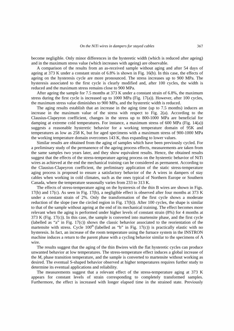
become negligible. Only minor differences in the hysteretic width (which is reduced after ageing) and in the maximum stress value (which increases with ageing) are observable.
A comparison of the results from an as-received sample without aging and after 54 days of ageing at 373 K under a constant strain of 6.8% is shown in Fig. 16(b). In this case, the effects of ageing on the hysteresis cycle are more pronounced. The stress increases up to 900 MPa. The hysteresis associated to the first cycle is clearly modified and, after 100 cycles, the width is reduced and the maximum stress remains close to 900 MPa.
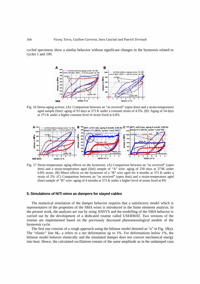
After ageing the sample for 7.5 months at 373 K under a constant strain of 6.8%, the maximum stress during the first cycle is increased up to 1000 MPa (Fig. 17(a)). However, after 100 cycles, the maximum stress value diminishes to 900 MPa, and the hysteretic width is reduced.
The aging results establish that an increase in the aging time (up to 7.5 months) induces an increase in the maximum value of the stress with respect to Fig. 2(a). According to the Clausius-Clapeyron coefficient, changes in the stress up to 800-1000 MPa are beneficial for damping at extreme cold temperatures. For instance, a maximum stress of 600 MPa (Fig. 14(a)) suggests a reasonable hysteretic behavior for a working temperature domain of 95K and temperatures as low as 258 K, but for aged specimens with a maximum stress of 900-1000 MPa the working temperature domain overcomes 143 K, thus expanding to lower values.
Similar results are obtained from the aging of samples which have been previously cycled. For a preliminary study of the permanence of the ageing process effects, measurements are taken from the same samples two years later, and they show equivalent results. Hence, the obtained results suggest that the effects of the stress-temperature ageing process on the hysteretic behavior of NiTi wires as achieved at the end the mechanical training can be considered as permanent. According to the Clausius-Clapeyron coefficient, the preliminary application of the static stress-temperature aging process is proposed to ensure a satisfactory behavior of the A wires in dampers of stay cables when working in cold climates, such as the ones typical of Northern Europe or Southern Canada, where the temperature seasonally varies from 233 to 313 K.
The effects of stress-temperature aging on the hysteresis of the thin B wires are shown in Figs. 17(b) and 17(c). As seen in Fig. 17(b), a negligible effect is observed after four months at 373 K under a constant strain of 2%. Only the transformation of the first cycle shows a moderate reduction of the slope (see the circled region in Fig. 17(b)). After 100 cycles, the shape is similar to that of the sample without ageing at the end of its mechanical training. The effect becomes more relevant when the aging is performed under higher levels of constant strain (8%) for 4 months at 373 K (Fig. 17(c)). In this case, the sample is converted into martensite phase, and the first cycle (labelled as “a” in Fig. 17(c)) shows the classic behavior associated to the reorientation of the martensite with stress. Cycle 100th (labelled as “b” in Fig. 17(c)) is practically elastic with no hysteresis. In fact, an increase of the room temperature using the furnace system in the INSTRON machine induces a return to the parent phase with a cycling behavior similar to the specimens of A wire.
The results suggest that the aging of the thin Bwires with the flat hysteretic cycles can produce unwanted behavior at low temperatures. The stress-temperature effect induces a global increase of the Ms phase transition temperature, and the sample is converted to martensite without working as desired. The eventual S-shaped behavior observed at higher temperatures requires further study to determine its eventual applications and reliability.
The measurements suggest that a relevant effect of the stress-temperature aging at 373 K appears for constant levels of strain corresponding to completely transformed samples. Furthermore, the effect is increased with longer elapsed time in the strained state. Previously
367
Vicenç Torra, Guillem Carreras, Sara Casciati and Patrick Terriault
cycled specimens show a similar behavior without significant changes in the hysteresis related to cycles 1 and 100.
Fig. 16 Stress-aging actions. (A): Comparison between an “as received” (open dots) and a strain-temperature
aged sample (line): aging of 93 days at 373 K under a constant strain of 4.5%. (B): Aging of 54 days at 373 K under a higher constant level of strain fixed at 6.8%
Fig. 17 Stress-temperature aging effects on the hysteresis. (A) Comparison between an “as received” (open dots) and a strain-temperature aged (line) sample of “A” wire: aging of 230 days at 373K under 6.8% strain. (B) Minor effects on the hysteresis of a “B” wire aged for 4 months at 373 K under astrain of 2%. (C) Comparison between an “as received” (open dots) and a strain-temperature aged (line) sample of “B” wire: aging of 4 months at 373 K under a higher level of strain fixed at 8%
5. Simulations of NiTi wires as dampers for stayed cables The numerical simulation of the damper behavior requires that a satisfactory model which is
representative of the properties of the SMA wires is introduced in the finite elements analysis. In the present work, the analyses are run by using ANSYS and the modelling of the SMA behavior is carried out by the development of a dedicated routine called USERMAT. Two versions of the routine are implemented based on the previously discussed phenomenological models of the hysteresis cycle.
The first one consists of a rough approach using the bilinear model denoted as “a” in Fig. 18(a). The “elastic” line M0- a refers to a net deformation up to 1%. For deformations below 1%, the bilinear model behaves elastically and the simulated damper does not convert mechanical energy into heat. Hence, the calculated oscillations remain of the same amplitude as in the undamped case.
368
On the NiTi wires in dampers for stayed cables
For strains overcoming 1%, the bilinear model shows a faster initial decay of the oscillations amplitude.
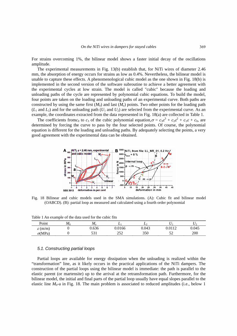
The experimental measurements in Fig. 13(b) establish that, for NiTi wires of diameter 2.46 mm, the absorption of energy occurs for strains as low as 0.4%. Nevertheless, the bilinear model is unable to capture these effects. A phenomenological cubic model as the one shown in Fig. 18(b) is implemented in the second version of the software subroutine to achieve a better agreement with the experimental cycles at low strain. The model is called "cubic" because the loading and unloading paths of the cycle are represented by polynomial cubic equations. To build the model, four points are taken on the loading and unloading paths of an experimental curve. Both paths are constructed by using the same first (M0) and last (Me) points. Two other points for the loading path (L1 and L2) and for the unloading path (U1 and U2) are selected from the experimental curve. As an example, the coordinates extracted from the data represented in Fig. 18(a) are collected in Table 1.
The coefficients fromc0 to c3 of the cubic polynomial equation, = c33 + c22 + c1 + c0, are determined by forcing the curve to pass by the four selected points. Of course, the polynomial equation is different for the loading and unloading paths. By adequately selecting the points, a very good agreement with the experimental data can be obtained.
Fig. 18 Bilinear and cubic models used in the SMA simulations. (A): Cubic fit and bilinear model
(OABCD). (B): partial loop as measured and calculated using a fourth order polynomial
Table 1 An example of the data used for the cubic fits
Point M0 Me L1 L2 U1 U2 (m/m) 0 0.636 0.0166 0.043 0.0112 0.045 (MPa) 0 531 252 350 52 200 5.1. Constructing partial loops Partial loops are available for energy dissipation when the unloading is realized within the
“transformation” line, as it likely occurs in the practical applications of the NiTi dampers. The construction of the partial loops using the bilinear model is immediate: the path is parallel to the elastic parent (or martensite) up to the arrival at the retransformation path. Furthermore, for the bilinear model, the initial and final parts of the partial loop usually have equal slopes parallel to the elastic line M0-a in Fig. 18. The main problem is associated to reduced amplitudes (i.e., below 1
369

Vicenç Torra, Guillem Carreras, Sara Casciati and Patrick Terriault
%). When the stress associated to the external load does not overcome the end point of the elastic part (“a” in Fig. 18(a)), the hysteretic area is zero and the damper does not produce any damping action.
When the cubic model is adopted, the representation of partial or internal loops is somewhat complex and requires more working hypotheses than in the bilinear case. To model the partial cycles inside the hysteresis, a further polynomial equation is derived by assigning the location and the slope at the beginning and at the end of the partial cycle. In Fig. 18(b), the partial cycle starting at the strain level * is drawn by using a fourth degree polynomial fit (curve B) passing by the three points *, a, O; namely, they represent the initial point of the unloading, the 20% of the associated deformation (O-a) and the origin (O) of the hysteresis cycle, respectively.
Furthermore, the retransformation curve of the internal loop (curve C in Fig. 18(b)) is drawn by using two slopes (in O and in M) and three points r, b and M. The fit return point r remains relatively close to the initial point *. The choice of 20% for the initial (a) and residual deformation (b) permits a satisfactory asymptotical approach of the calculated curves to the experimental data. Experimental tests are realized to compare the experimental energy with the calculated one for partial loops. The differences remain under 20%.
In addition to the simulations, a direct approach permits the evaluation of the energy dissipated in the SMA damper, as discussed in Subession2.2. It uses a quadratic fit of the hysteretic energy plotted against the deformation of the SMA, as shown in Figures from 4 to 7 for NiTi wires of different diameters.
5.2 Simulation of the ELSA experimental measurements The ELSA cable is inclined at 21 with respect to the ground level, and it was built using four
sets of steel wires of diameter 15 mm each situated inside a polyethylene tube refilled with wax. The tension in the cable is 250 kN and the tests are carried out by applying a vertical force on the cable at 27% of its length from the ground anchorage. When a SMA damper is added, it is installed vertically at 22% of the cable's length from the ground anchorage. The SMA damper consists of only one trained wire of 2.46 mm diameter and a length greater than 4000 mm. Series of measurements were realized on the studied cable. In the steady state, the SMA damper reduces the maximum oscillation amplitude to one third of its undamped value.
The finite element model of the ELSA cable is created by using the Mechanical APDL interface of the ANSYS 13.0 software. The cable is represented by 100 beam elements (element type: BEAM3) and both edges are clamped (displacements and rotations are fixed to zero). According to the data of the physical cable, the actual cross-section is made of four stranded steel cables (with Young’s modulus: E=200 GPa) of diameter 15 mm each inserted into a polyethylene sheath (E = 600 MPa) with a thickness of 3.5 mm and 76 mm of external diameter. The sheath is filled with wax (E = 27 MPa). The cable has a mass per unit length of approximately mL=9.8 kg/m. Knowing the dimensions of the cable (length L=45 m and area A=0.0045 m2) and the material properties, the Stiffness-Inertia (EI = 35 400 Nm2) and the Stiffness-Area (EA = 1.3×10⁸ N) products are calculated for the entire cross section.
For the analyses, an equivalent density *, Young's modulus E* and moment of inertia I* are defined in order to simulate an uniform circular beam having the same properties of the cable made of different materials. In particular, the following products are set equal to known values representing the real cable:*A=mL=9.8 kg/m, E*I*=EI = 35 400 Nm2, and E*A = EA = 1.3×10⁸ N.
370

On the NiTi wires in dampers for stayed cables
Then, the equivalent properties of the cable are given as follows: *=2175 kg/m3, E*= 29 GPa, and I*=1.2×10⁻⁶ m4.
The damper built for the ELSA cable is made of a single, 4 m long NiTi wire having a diameter of 2.46 mm. It is modeled in ANSYS by using a single bar element (element type: LINK180) attached to the cable at one end and pinned to the ground at the other end. The behavior of the SMA wire is described by the cubic model in Fig. 21 and is implemented in ANSYS through the USERMAT routine as previously discussed.
The results associated to the ELSA model are visualized in Fig. 19. The cable is excited by a sinusoidal force varying between 0 and 100 N at a frequency equal to 1.81Hz when the cable alone is considered, and equal to 2.04Hz when the NiTi damper is used. After the first 20s of excitation, the force is released and the cable oscillates freely for other 20 seconds. The numeric approach is first carried out for the “steel cable” alone, with and without the effect of the wax (Fig. 19(a)). Then, the action of the SMA damper is evaluated by comparing the results of the simulations without and with the SMA dampers and by directly calculating the frequency values in both cases (Fig. 19(b)). The experimental results and the numerical simulations are satisfactorily coherent one with the other, and they show the relevant and clear effects of damping induced by the SMA wire in the steel stayed cable.
Fig. 19 ELSA cable No 1, displacements at midspan. (A): Simulations of the cable alone with and without
wax (the latter information was unavailable from the experiments). (B): Effects of a damper made by only one wire of SMA, and direct evaluation of the frequency changes
Fig. 20 Simulations of the free and damped oscillations of the IFSTTAR cable. (A): bilinear SMA model.
(B): cubic SMA model. From the simulations, an evolution of the frequency is also detected
371

Vicenç Torra, Guillem Carreras, Sara Casciati and Patrick Terriault
5.3 IFSTTAR cable simulations Numerical simulations similar to the ELSA ones are carried out for the IFSTTAR horizontal
cable with length of 50.5 m and mass per unit length of 16.1 kg/m. The cable is made of steel (E=200 GPa) and the initial tension is 960 kN. The actual cross-section is made of 159 stranded wires forming the core and 7 additional layers. The outer diameter, cross-section area and moment of inertia are 55.6 mm, 1936 mm2 and 3.03×10⁻⁷ m4, respectively.
The measurements realized on the IFSTTAR cable relate to a transitory excitation. In this case, the cable’s oscillations are induced by a Heaviside step. The situation is dynamically different with respect to the measurements taken at the ELSA facility, where periodic and resonant actuations are used. In the IFSTTAR experiment, a vertical force either of 1, 2, 3 or 4 kN is applied to reach an initial displacement of the cable. A sudden release of the force (which can then be represented as a Heaviside step) produces spontaneous oscillations with a decay associated to the frictional actions on the cable.
The SMA damper specifically designed for the IFSTTAR cable consists of two trained wires of diameter 2.46 mm and a length close to 1260 mm. To achieve the required large fracture-life according to Fig. 2(c), the length of the used SMA wire needs to be situated near 1 – 1.5% of the peak to peak oscillation amplitudes of the cable. For the IFSTTAR damper, the available experimental device is short in comparison with the appropriate length, thus justifying the need for two NiTi wires. Several sets of measurements were realized by varying the positions of the cable actuator and the measurement sensor (L/4, L/8, …). For each position, the action of the SMA damper resulted to be clearly effective. The numerical simulations yielding the results in Fig. 20 refer to the case where the actuator and the measurement sensor are situated in the center of the cable at L/2.
The results of the IFSTTAR simulations obtained by adopting a bilinear model show an unrealistic damping effect for the low oscillation amplitudes herein considered (Fig. 20(a)). In Fig. 20(b), the adoption of a cubic model, instead, yields numerical results similar to the experimental measurements. From the damped measurements in Fig. 20(b), a relevant reduction of the oscillation amplitudes is observed. The frequency evolution is also directly determined from the simulation with the SMA damper. 6. Conclusions
The energetic dissipative properties of NiTi wires are studied using specimens of different
diameters. In general, the large fatigue life of a damper for stayed-cables implies a low working range of net strain near 1 %. Hence, the dissipated energy against the oscillation amplitude is quantified for SMA strains from 0 to 2.5%. An empirical approach is adopted to derive a rough estimate of the energy absorbed by the SMA damper as a function of the oscillations amplitude (i.e., the SMA strain) corrected by a factor which accounts for the frequency effects. The pre-stressing is also discussed. The NiTi specimens show a satisfactory behavior in damping stayed cables with an appropriate fatigue life. The effects of external temperatures (summer-winter) and the self-heating consequences are quantified. For low strain ranges, as required to have a suitable fatigue-life, their effects are not relevant. The studies of stress-aging effects show that such a process offers an efficient possibility for extending the use of SMA dampers in extreme winter temperatures. The SMA hysteretic behavior is characterized accounting for the influence of several aspects relevant to practical implementations, such as the martensitic transformation, the
372
On the NiTi wires in dampers for stayed cables
latent heat, the thermal couplings with the surroundings (i.e., the air flows) and, eventually, the parasitic effects of the testing equipment.
A polynomial fit to the phenomenological model of the NiTi hysteresis cycle is then used to carry out the finite element analyses (FEA) aiming to simulate the dynamics of the cable-damper system under external loading. Such an approach relies on the partial and internal loops of the hysteresis cycle to dissipate energy during the cable oscillations. The numerical analyses reveal the limitations associated to a bilinear model for strains under 1%. Instead, the implementation of a cubic model inside a FEA environment as, for instance, ANSYS, furnishes numerical results quite similar to the experimental ones. In the considered cases, the SMA damper reduces the oscillation amplitudes, in the steady state, to 1/3-1/4 of the undamped oscillation. Acknowledgments
V.T. acknowledges Pablo Riquelme for the support in the measurements carried out using the
MTS and INSTRON testing equipment at CAB-IB facility, in Bariloche, Argentina. The relevant support of Dr. G. Magonette and colleagues at ELSA (EU, Ispra, Italy), of Dr. L. Dieng and colleagues at IFSTTAR (Bouguenais, Nantes, France) and of Dr. A. Marzi in Pavia (Italy), for the measurements realized in their Institutions, is gratefully acknowledged.. References Andrawes, B. and DesRoches, R. (2007), “Comparison between shape memory alloy seismic restrainers and
other bridge retrofit devices”, J. Bridge Eng., 12(6), 700-709. Ben Mekki, O. and Auricchio, F. (2011), “Performance evaluation of shape-memory-alloy super elastic
behavior to control a stay cable in cable-stayed bridges”, Int. J. Nonlinear Mech., 46(2), 470-477. Carreras, G., Casciati, F., Casciati, S., Isalgue, A., Marzi, A. and Torra, V. (2011), “Fatigue laboratory tests
toward the design of SMA portico-braces”, Smart Struct. Syst., 7(1), 41-57. Casciati, F., Casciati, S. and Faravelli, L. (2007), “Fatigue characterization of a Cu-based shape memory
alloy”, Proc. Est. Acad. Sci. - PH., 56(2), 207-217. Casciati, F., Casciati, S., Faravelli, L. and Marzi, A. (2011), “Fatigue damage accumulation in a Cu-based
shape memory alloy: preliminary investigation”, CMC, 23(3), 287-306. Casciati, S. and Faravelli, L. (2008), “Structural components in shape memory alloy for localized energy
dissipation”, Comput. Struct., 86(3-5), 330-339. Casciati, S. and Marzi, A. (2010), “Experimental studies on the fatigue life of shape memory alloy bars”,
Smart Struct. Syst., 6(1), 73-85. Casciati, S. and Marzi, A. (2011), “Fatigue tests on SMA bars in span control”, Eng. Struct., 33(4),
1232-1239. De-Castro-Bubani, F., Sade, M., Torra, V., Lovey, F. and Yawny, A. (2013), “Stress induced martensitic
yransformations and phases stability in Cu-Al-Be shape memory single crystals”, Mater. Sci. Eng., 583, 129-139.
DesRoches, R. and Smith, B. (2004), “Shape memory alloys in seismic resistant design and retrofit: a critical review of their potential and limitations”, J. Earthq. Eng., 8(3), 415-429.
Di Cesare, A., Ponzo, F.C., Nigro, D., Dolce, M. and Moroni, C. (2012), “Experimental and numerical behaviour of hysteretic and visco-recentring energy dissipating bracing systems”, Bull Earthq. Eng., 10, 1585-1607.
Dolce, M. and Cardone, D. (2001a), “Mechanical behaviour of shape memory alloys for seismic applications 1. Martensite and austenite NiTi bars subjected to torsion”, Int . J. Mech. Sci., 43, 2631-2656
Dolce, M. and Cardone, D. (2001b), “Mechanical behaviour of shape memory alloys for seismic
373

Vicenç Torra, Guillem Carreras, Sara Casciati and Patrick Terriault
applications 2. Austenite NiTi wires subjected to tension”, Int . J. Mech. Sci., 43, 2657-2677 Dolce, M. and Cardone, D. (2006), “Theoretical and experimental studies for the application of shape
memory alloys in civil engineering”, J. Eng. Mater.- T ASME, 128(3), 302-311. Eggeler, G., Khalil-Allafi, J., Gollerthan, S., Somsen, C., Schmahl, W. and Sheptyakov, D. (2005), “On the
effect of aging on martensitic transformations in Ni-rich NiTi shape memory alloys”, Smart Mater. Struct., 14, S186 doi:10.1088/0964-1726/14/5/002.
Indirli, M. and Castellano, M.G. (2008), “Shape memory alloy devices for the structural improvement of masonry heritage structures”, Int. J. Architect Herit., 2(2), 93-119.
Isalgue, A., Torra, V., Yawny, A. and Lovey, F.C. (2008), “Metastable effects on martensitic transformation in SMA Part VI. The Clausius–Clapeyron relationship”, J. Therm. Anal Calorim., 91(3), 991-998.
Otsuka, K. and Wayman, C.M. (Eds.) (1998), Shape memory materials, Cambridge University Press, UK. Lovey, F.C. and Torra, V. (1999), “Shape memory in Cu-based alloys: phenomenological behavior at the
mesoscale level and interaction of martensitic transformation with structural defects in Cu-Zn-Al”, Prog. Mater. Sci., 44(3) 189-289.
Ma, H. and Cho, C. (2008), “Feasibility study on a superelastic SMA damper with re-centring capability”, Mater. Sci. Eng., A473, 290-296.
Otsuka, K. and Wayman C.M. (1998), Shape memory materials, Cambridge University Press, Cambridge, UK.
Song, G., Ma, N. and Li, H.N. (2006), “Applications of shape memory alloys in civil structures”, Eng. Struct., 28(9), 1266-1274.
Speicher, M.S., DesRoches, R. and Leon, R.T. (2011), “Experimental results of a NiTi shape memory alloy (SMA)-based recentering beam-column connection”, Eng. Struct., 33(9), 2448-2457.
Torra, V., Auguet, C., Carreras, G., Dieng, L., Lovey, F.C. and Terriault, P. (2012a), “The SMA: an effective damper in civil engineering that smoothes oscillations”, Mater. Sci. Forum., 706-709, 2020-2025.
Torra, V., Auguet, C., Isalgue, A., Lovey, F.C. and Terriault, P. (2012b), “The SMA was a tool for damping the induced oscillations in civil structures. Application to earthquake mitigation in family homes and to stayed cables for bridges”, Proceedings of the ICOMAT, Osaka, Japan.
Torra, V., Auguet, C., Isalgue, A., Carreras, G., Terriault, P. and Lovey, F.C. (2013a), “Built in dampers for stayed cables in bridges via SMA. The SMARTeR-ESF project: a mesoscopic and macroscopic experimental analysis with numerical simulations”, Eng. Struct., 49, 43-57.
Torra, V., Isalgue, A., Auguet, C.,, Casciati, F., Casciati, S. and Terriault, P. (2013b), “SMA dampers for cable vibration: an available solution for oscillation mitigation of stayed cables in bridges”, Adv. Sci. Technol., 78, 92-102.
Torra, V., Isalgue, A., Auguet, C., Carreras, G., Lovey, F.C. and Terriault, P. (2013c), “Damping in civil engineering using SMA. Part II. particular properties of NiTi for damping of stayed cables in bridges”, Can. Metall. Quart., 52, 81-89.
Torra, V., Auguet, C., Isalgue, A., Carreras, G. and Lovey, F.C. (2013d), “Metastable effects on martensitic transformation in SMA Part IX. Static aging for morphing by temperature and stress”, J Therm. Anal Calorim., 112(2), 777-780
Torra, V., Isalgue, A., Martorell, F., Lovey, FC. and Terriault, P. (2010), “Damping in civil engineering using SMA. part I. particular properties of CuAlBe for damping of family houses”, Can. Metall. Quart., 49(2), 179-190
Torra, V., Isalgue, A., Martorell, F., Terriault, P. and Lovey, F.C. (2007), “Built in dampers for family homes via SMA: An ANSYS computation scheme based on mesoscopic and microscopic experimental analyses”, Eng. Struct., 29(8), 1889-1902.
FC
This paper was presented at the special session on Shape Memory Alloys at the International Conference on Smart Structure and Systems (ICOSS13) hosted in Jeju (Korea) in September 2013 under the big umbrella of 2013 World Congress on Advances in Structural Engineering and Mechanics (ASEM13).
374
Copyright © 2022 FDOKUMEN