Estimation de la résistance de l'interface de composite époxyde-renfort en alliage à mémoire de...
8
Comptes Rendus des JNC 16 Toulouse 2009 Estimation de la résistance de l’interface de composite époxyde - renfort en alliage à mémoire de forme (NiTi) Estimation of the Interfacial Shear Strength in a NiTi Shape Memory Fibre-Epoxy Matrix Composite Yousef Payandeh 1 , Fodil Meraghni 1 , Etienne Patoor 1 , André Eberhardt 2 Laboratoire de Physique et Mécanique des Matériaux (LPMM-UMR CNRS 7554) 1 : Arts et Métiers ParisTech, CER Metz, 4 rue Augustin Fresnel, 57078, Metz, France [email protected] 2 : ENIM, Ile du Saulcy, 57045, Metz, France Résumé Dans ce travail, la décohésion de l’interface du composite mono fibre : époxyde M10 renforcée par une fibre de NiTi a été étudiée en utilisant une méthode analytique combiné avec une approche expérimentale fondée sur l’essai d’arrachement (pull-out). L’effet de la transformation austénite martensite est discriminé en comparant le comportement du composite à renfort AMF avec le comportement du composite à renfort en fils en acier caractérisé par l’absence de transformation martensitique. Les observations in situ de la décohésion de l’interface et de glissement au cours de l’essai d’arrachement ont été effectuées à l'aide d'un appareil photo numérique positionnée à l'arrière d'un polariscope. Il a été observé que la charge de décohésion pour les éprouvettes avec la fibre de NiTi est inférieure à celle de l'acier. Il est associé à la différence entre les modules d'élasticité de la fibre. Néanmoins, on démontre que les résistances au cisaillement de l’interface ne sont pas identiques dans les deux systèmes analysés. Ce paramètre dépend de la résistance au cisaillement de la matrice ainsi que les conditions de la surface de fibres. Ce dernier change dès que la fibre amorce le processus de la transformation de phase. Abstract In this work, the interfacial debonding in a single NiTi fibre reinforced epoxy matrix composite was investigated using a micromechanic analytical method combined with an experimental approach. For comparison, some specimens with a steel fibre have been tested and analysed. The in situ observations of the interfacial debonding and sliding behaviour during the pull-out test were carried out using a digital camera which has been located in back of a polariscope. It has been observed that the debonding load for martensitic NiTi fibre is, significantly, less than that for steel fibre. It is associated with the difference between the elastic modulus of the fibres. Nevertheless, the interfacial shear strength, in both systems, are not identical. This parameter is dependent on the matrix shear strength as well as the fibre surface conditions. The latter changes as soon as the fibre meets forward or reverse phase transformation. Mots Clés : fibre d’AMF, NiTi, Décohésion de l’interface, Résistances au cisaillement de l’interface. Keywords: SMA fibre, NiTi, Interfacial debonding, interfacial shear strength. 1. Introduction Shape Memory Alloys (SMAs) have been used as reinforcement of composite materials due to the particular properties such as shape memory effect (SME), superelastisity and high damping capacity. Nevertheless, some fibre characteristics change during phase transformation that can affect the interfacial properties. Therefore, prior to implementing these composites into real structures, it needs to work on the fibre phase transformation and interfacial characteristics of these kinds of composite. It is well recognized that the mechanical behaviour of many composite materials depends largely on the properties of the fibre/matrix interface [1-4]. One of the fundamental problems in the field of fibre–polymer composites deals with the control of the degree of adhesion between the usually more rigid fibre and the relatively ductile polymer matrix [5]. In fact, the interfacial debonding between fibre and matrix is the most important factor which leads to the failure of composite materials [6, 7]. It is obvious that when shear stress between constituents increases upon the interfacial shear strength, interfacial debonding will start hal-00397619, version 1 - 22 Jun 2009 Manuscrit auteur, publié dans "JNC 16, Toulouse : France (2009)"
-
Upload
artsetmetiersparistech -
Category
Documents
-
view
0 -
download
0
Transcript of Estimation de la résistance de l'interface de composite époxyde-renfort en alliage à mémoire de...

Comptes Rendus des JNC 16 Toulouse 2009
Estimation de la résistance de l’interface de composite époxyde -
renfort en alliage à mémoire de forme (NiTi)
Estimation of the Interfacial Shear Strength in a NiTi Shape Memory
Fibre-Epoxy Matrix Composite
Yousef Payandeh
1, Fodil Meraghni
1, Etienne Patoor
1, André Eberhardt
2
Laboratoire de Physique et Mécanique des Matériaux (LPMM-UMR CNRS 7554)
1 : Arts et Métiers ParisTech, CER Metz, 4 rue Augustin Fresnel, 57078, Metz, France [email protected]
2 : ENIM, Ile du Saulcy, 57045, Metz, France
Résumé
Dans ce travail, la décohésion de l’interface du composite mono fibre : époxyde M10 renforcée par une
fibre de NiTi a été étudiée en utilisant une méthode analytique combiné avec une approche expérimentale fondée sur l’essai d’arrachement (pull-out). L’effet de la transformation austénite martensite est discriminé en comparant le comportement du composite à renfort AMF avec le comportement du composite à renfort en fils en acier caractérisé par l’absence de transformation martensitique. Les observations in situ de la décohésion de l’interface et de glissement au cours de l’essai d’arrachement ont été effectuées à l'aide d'un appareil photo numérique positionnée à l'arrière d'un polariscope. Il a été observé que la charge de décohésion pour les éprouvettes avec la fibre de NiTi est inférieure à celle de l'acier. Il est associé à la différence entre les modules d'élasticité de la fibre. Néanmoins, on démontre que les résistances au cisaillement de l’interface ne sont pas identiques dans les deux systèmes analysés. Ce paramètre dépend de la résistance au cisaillement de la matrice ainsi que les conditions de la surface de fibres. Ce dernier change dès que la fibre amorce le processus de la transformation de phase.
Abstract
In this work, the interfacial debonding in a single NiTi fibre reinforced epoxy matrix composite was investigated using a micromechanic analytical method combined with an experimental approach. For comparison, some specimens with a steel fibre have been tested and analysed. The in situ observations of the interfacial debonding and sliding behaviour during the pull-out test were carried out using a digital camera which has been located in back of a polariscope. It has been observed that the debonding load for martensitic NiTi fibre is, significantly, less than that for steel fibre. It is associated with the difference between the elastic modulus of the fibres. Nevertheless, the interfacial shear strength, in both systems, are not identical. This parameter is dependent on the matrix shear strength as well as the fibre surface conditions. The latter changes as soon as the fibre meets forward or reverse phase transformation.
Mots Clés : fibre d’AMF, NiTi, Décohésion de l’interface, Résistances au cisaillement de l’interface.
Keywords: SMA fibre, NiTi, Interfacial debonding, interfacial shear strength.
1. Introduction Shape Memory Alloys (SMAs) have been used as reinforcement of composite materials due to the
particular properties such as shape memory effect (SME), superelastisity and high damping capacity. Nevertheless, some fibre characteristics change during phase transformation that can affect the interfacial properties. Therefore, prior to implementing these composites into real structures, it needs to work on the fibre phase transformation and interfacial characteristics of these kinds of composite.
It is well recognized that the mechanical behaviour of many composite materials depends largely on the properties of the fibre/matrix interface [1-4]. One of the fundamental problems in the field of fibre–polymer composites deals with the control of the degree of adhesion between the usually more rigid fibre and the relatively ductile polymer matrix [5]. In fact, the interfacial debonding between fibre and matrix is the most important factor which leads to the failure of composite materials [6, 7]. It is obvious that when shear stress between constituents increases upon the interfacial shear strength, interfacial debonding will start
hal-0
0397
619,
ver
sion
1 -
22 J
un 2
009
Manuscrit auteur, publié dans "JNC 16, Toulouse : France (2009)"
Comptes Rendus des JNC 16 Toulouse 2009
immediately. It is generally agreed that the higher the critical debonding stress, the stronger the composite material will be [6]. In fact, when the composites are loaded, stress transfer would take place across the fibre/matrix interface. The mechanical properties of the composites depend critically upon the efficiency of the stress transfer during fibre pull-out [1]. A composite system with large IFSS (excellent fibre-matrix bonding) has high strength due to effective stress transfer from the matrix to the fibres [3].
Fibre-matrix adhesion can be characterized in terms of the interfacial shear strength, IFSS. It is important to consider the stress concentrations at the fibre-matrix interface since interfacial failure initiates from such regions. Other than IFSS, the interfacial parameters of composite systems include the matrix shrinkage pressure on the fibre, and the interfacial coefficient of friction between the debonded fibre and the surrounding matrix material. These parameters can be determined from pull-out test data. [3]
Over the years several test methods, such as the pull-out, push-out and fragmentation tests, have been developed to characterise the fibre/matrix interface [1-22]. These tests are able to determine the interfacial shear strength (IFSS), a widely-used quantitative parameter to indicate the level of fibre/matrix adhesion. There is a renewed interest in using an energy-based criterion to characterise the fibre/matrix interface [4, 5, 11 and 21]. The parameter of interest is the interface fracture energy which is the energy per unit area needed to break the fibre/matrix interface [4].
The fibre pull-out test has been well accepted as one of the most important test methods developed as a means of investigating the interfacial adhesion quality and interfacial properties between fibres and matrix and the elastic stress transfer in the fibre pull-out problem [1-3, 6, 8, 10, 11, 15, 19, 20].
In the present work, the interfacial debonding in single fibre composite was investigated using an analytical method combined with the experimental results. The shape memory NiTi fibre with different phase transformation parameters have been employed in order to characterize the bonding characteristics. For comparison, the steel fibre composites have been tested and analysed.
2. Experimental procedure The composite material studied in this work is a near equiatomic NiTi shape memory fibre epoxy matrix
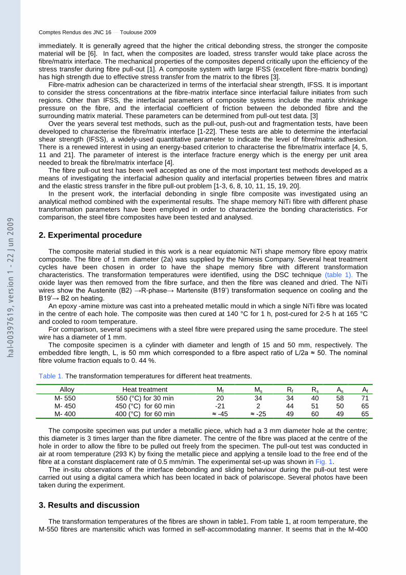
composite. The fibre of 1 mm diameter (2a) was supplied by the Nimesis Company. Several heat treatment cycles have been chosen in order to have the shape memory fibre with different transformation characteristics. The transformation temperatures were identified, using the DSC technique (table 1). The oxide layer was then removed from the fibre surface, and then the fibre was cleaned and dried. The NiTi wires show the Austenite (B2) →R-phase→ Martensite (B19’) transformation sequence on cooling and the B19’→ B2 on heating.
An epoxy -amine mixture was cast into a preheated metallic mould in which a single NiTi fibre was located in the centre of each hole. The composite was then cured at 140 °C for 1 h, post-cured for 2-5 h at 165 °C and cooled to room temperature.
For comparison, several specimens with a steel fibre were prepared using the same procedure. The steel wire has a diameter of 1 mm.
The composite specimen is a cylinder with diameter and length of 15 and 50 mm, respectively. The embedded fibre length, L, is 50 mm which corresponded to a fibre aspect ratio of L/2a ≈ 50. The nominal fibre volume fraction equals to 0. 44 %.
Table 1. The transformation temperatures for different heat treatments.
The composite specimen was put under a metallic piece, which had a 3 mm diameter hole at the centre;
this diameter is 3 times larger than the fibre diameter. The centre of the fibre was placed at the centre of the hole in order to allow the fibre to be pulled out freely from the specimen. The pull-out test was conducted in air at room temperature (293 K) by fixing the metallic piece and applying a tensile load to the free end of the fibre at a constant displacement rate of 0.5 mm/min. The experimental set-up was shown in Fig. 1.
The in-situ observations of the interface debonding and sliding behaviour during the pull-out test were carried out using a digital camera which has been located in back of polariscope. Several photos have been taken during the experiment.
3. Results and discussion The transformation temperatures of the fibres are shown in table1. From table 1, at room temperature, the
M-550 fibres are martensitic which was formed in self-accommodating manner. It seems that in the M-400
Alloy Heat treatment Mf Ms Rf Rs As Af
M- 550 550 (°C) for 30 min 20 34 34 40 58 71 M- 450 450 (°C) for 60 min -21 2 44 51 50 65 M- 400 400 (°C) for 60 min ≈ -45 ≈ -25 49 60 49 65
hal-0
0397
619,
ver
sion
1 -
22 J
un 2
009

Comptes Rendus des JNC 16 Toulouse 2009
and M-450 fibres, the stable phase at room temperature is R-phase, and there are likely some percents of residual austenite. Thus, by applying the external stress, the martensitic reorientation occurs in M-550 whilst in M-450 and M-400, the martensitic transformation takes place. From Fig. 2, the stress at which the martensite reorients in the M-550 fibres is about 100 MPa (F=80 N) at room temperature. In the case of M-450 fibres (Fig. 3-a) the martensitic transformation occurs under a stress about 140 MPa (F≈110 N). The M-400 fibres transform to martensite under a stress about 250 MPa (F≈200 N) at the same temperature (Fig. 3-b).
0 10 20 30 40 50 60
0
100
200
400
600
800
1000
1200
Normal Strain(%)
Norm
al
Str
ess (
MP
a)
M-550 °C, 30 min
Fig.1–Experimental set-up (a) side section (b) up
view
Fig. 2- Stress -Strain diagram for M-550 fibre
( a ) ( b)
0 2 4 6 8 10 12 14 160
140
400
600
800
1000
1200
1400
Normal Strain(%)
Norm
al
Str
ess (
MP
a)
M-450 °C, 60 min
0 5 10 15
0
250
500
1000
1500
Normal Strain(%)
Norm
al
Str
ess (
MP
a)
M-400 °C, 60 min
Fig. 3- Stress -Strain diagram for (a) M-450 and (b) M-400 fibre
When the fibres are embedded in the matrix the free part of the fibres, in some cases, behaves same as above; but the embedded part behaves differently. According to in-situ observation (Fig.4), the debonding starts from the fibre entry point and proceeds to the embedded end along the interface until the entire fibre is debonded. This process occurs slowly and when the bonded length reaches a critical embedded length the debonding phenomenon continues so rapidly. The fibre is then pulled out of the resin matrix by a frictional pull-out process.
In comparison with the NiTi fibres, the steel wires are debonded more rapidly and the last debonded part is, significantly, greater than that of the others. In contrary, the debonding load, at which the debonding process starts, in this case, is more than that for the NiTi one. In the other word, the interfacial failure, for the steel wires, starts in high values of load, proceeds faster and reaches the critical embedded length more rapidly in comparison with the NiTi fibres. This critical embedded length for steel fibres is remarkable, whilst it is small for NiTi fibres. The critical embedded length for the fibres with different Young’s modulus is shown in Fig 5. From this figure the critical embedded length for steel fibre is about 20 mm whist it is about 5 mm for the NiTi fibres. The phase transformations in NiTi fibres are neglected in the Fig. 5. In the cases of M-450 and M-550, the stresses in which the debonding occurs are always greater than the transformational
σp (a)
(b)
hal-0
0397
619,
ver
sion
1 -
22 J
un 2
009

Comptes Rendus des JNC 16 Toulouse 2009
stresses. In the other words, in these specimens, the debonding takes place after transformation of the free part of the fibre. The in-situ observation shows that in these cases, almost there is no critical embedded length in comparison with the steel fibre specimens. Fig. 4 shows the debonding position and stress distribution for both NiTi and steel fibres.
(a)
(b)
Fig. 4- Debonding process and stress distribution along the fibre embedded length during the test.
(a) steel and (b) M-400 NiTi fibre. In both cases, the first image (left hand side) was taken before
test and the last one was taken just after completed debonding. The arrows show the position of
debonding.
0 5 10 15 20 25 30 35 40Specimen length (mm)
Ma
x.
Sh
ea
r S
tress (
MP
a)
Ef=27 GPa
Ef=33 GPa
Ef=210 GPa
0 5 10 15 20 25 30 35 40 45 50
0
0.1
0.2
0.3
0.4
0.5
0.6
0.7
0.8
0.9
1
Fibre embedded length (mm)
Beta
Ef=27e3
Ef=33e3
Ef=40e3
Ef=210e3
Fig. 5- Maximum shear stress vs. specimen length for different fibre’s Young modului
Fig. 6- Beta vs. embedded fibre length for different fibre’s Young moduli
As it is mentioned before, the debonding starts from the fibre entry point, thus the shear stress expected to have the maximum value at this point. That is in good accordance with the photoelastic analysis given by J.M. Vazquez-Rodriguez et al. [10]. However, by applying a load on free end of the fibre, the maximum interfacial shear stress, MISS, will be at the entry point. It increases linearly with increasing the normal applied stress [23]:
F
max = β. σp (eq. 1) the parameter β is determined as below:
Deb
on
ded
zo
ne
hal-0
0397
619,
ver
sion
1 -
22 J
un 2
009

Comptes Rendus des JNC 16 Toulouse 2009
β = γ sinh(γs) [B. cosh(γs) + C. sinh(γs)] + Cγ/2 (eq. 2) where B, C, γ, are the constants (table 2) and s is the fibre’s aspect ratio. In the table 2, the effect of the fibre’s Young modulus as well as the embedded length on the parameter β were illustrated. As it seen, in the case of steel, this parameter is not identical for two different lengths.
When the MISS reaches a value denoted by, i (interfacial shear strength), it remains constant and no
longer increases with applied stress. Moreover, the debonding starts as soon as the MISS reaches i, and propagates while the load is applied. With propagation of debonding, the MISS will be at the debonded/ undebonded transition zone. In the other word, the position of maximum shear stress varies with propagation of the debonding process.
Table 2. The different constants for different fibre lengths and Young’s moduli using a = 0.5, b = 7.5, m = 0.37, Em = 3 GPa.
Ef = 27 (GPa) Ef = 33 (GPa) Ef = 210 (GPa)
l = 10 l = 50 l = 10 l = 50 l = 10 l = 50
B (-)
–0.0386 –0.0386 –0.0468 –0.0468 –0.2381 –0.2381 C (-) 0.0696 0.0386 0.0917 0.0468 0.5556 0.2385 γ (-) 0.2064 0.2064 0.1875 0.1875 0.0831 0.0831 β (-) 0.0994 0.0992 0.0897 0.0894 0.0379 0.0317
The material parameter β depends on the Young’s modulus of the fibre (Fig. 6). The reported values of
Young’s modulus vary from 26 to 70 GPa for martensite and 30 to 70 GPa for austenitic NiTi [24-29]. In this work, the young’s modulus of martensite has been determined experimentally. It equals to 27 GPa for apparent value and 50 GPa for the real one. Moreover, this parameter has been also determined by mechanical tests for R-phase and is equal to 33 GPa. Since the fibre displacement plays an important role in debonding process, it seems better to use the apparent Young’s modulus, instead of the real one. For the parameter β, by using the apparent modulus of martensite, the values of 0.0317, 0.0808, 0.0894 and 0.0992 are calculated for steel, M-400, M-450 and M-550, respectively (Table 3). It should be noted that these values correspond to the fibre embedded length greater than the critical one.
Since β is independent of applied stress, as discussed before, the MISS increases linearly with applied
stress and remains constant as soon as the MISS is equal to i. Fig. 7 shows this relationship, schematically.
As it was noted before, when the MISS reaches to i, the debonding starts. In the other hand, at this time the applied stress is equal to σp
*, thus:
i =β.σp* (eq. 3)
σp
* is the debonding stress (i. e. applied stress at the beginning of debonding). The interfacial shear
strength, i, is calculated when the debonding stress is known. From experimental results, the debonding stress is 140 MPa (F ≈110 N) for M-550/ epoxy (Fig. 8), 160 MPa (F ≈ 125 N) for M-450/ epoxy (Fig. 9), 115 MPa (F ≈ 90 N) for M-400/ epoxy (Fig. 10) and 285 MPa (F ≈225 N) in steel/ epoxy (Fig. 11) systems. The difference is associated with the difference between the elastic modulus of the fibres. By substituting these values into the equation 3, therefore, the interfacial shear strength will be between 9.2 and 14.4 MPa for these specimens, which is identical for different two kinds of fibre but the same matrix (Fig. 12). From Table 3, the interfacial shear strength is about 9 MPa when there is no phase transformation; and it is about 14 MPa when the fibres meet martensitic transformation/reorientation. According to S. Rossi et al, the interfacial shear strength for NiTi fibre/epoxy system has been reported to be equal to 13 MPa [30].
0 1 2 3 4 5 6 7 8 9 100
20
40
60
80
100
120
140
Fibre displacement (mm)
Force (
N)
onset of
debonding
Applied stress
Ma
x.
sh
ea
r s
tress
τi
σp*
hal-0
0397
619,
ver
sion
1 -
22 J
un 2
009

Comptes Rendus des JNC 16 Toulouse 2009
Fig. 7- Maximum shear stress vs. applied stress, τi and σp
* are interfacial shear strength and debonding stress,
respectively.
Fig. 8- Force - Displacement diagram for the specimen with M-550 NiTi fibre
Fig. 9- Force - Displacement diagram for the specimen with M-450 NiTi fibre
Fig. 10 - Force - Displacement diagram for the specimen with M-400 NiTi fibre
0 50 100 150 200 250 300 350
0
2
4
6
8
10
12
14
16
Applied stress (MPa)
Ma
x.
Sh
ea
r S
tress (
MP
a)
M550, p*=140 MPa
M450, p*=160 MPa
M400, p*=115 MPa
Steel, p*=285 MPa
Fig. 11- Force - Displacement diagram for the specimen with steel fibre.
Fig. 12- Maximum shear stress vs. applied stress for different fibre’s Young moduli
According to above discussion, it should be noted that the debonding stress depends, strongly, on the
fibre’s Young modulus. However, the interfacial shear strength is, likely, independent of the kind of fibre, but it seems to be dependent on the martensitic transformation (MT)/ reorientation of the fibre. This phenomenon (MT) affects not only on the debonding initiation but also on the debonding propagation [31].
Table 3. Results summary
Deformation mode Ef (GPa) β(-) F (N) σp* (MPa) i (MPa)
NiTi (M), M550 M. Reorientation 27 (a) 0.0992 110 140 13.9
NiTi (R), M450 M. Transformation 33 (a) 0.0894 125 160 14.3
NiTi (R), M400 - 40 (a) 0.0808 90 115 9.3
Steel - 210 0.0317 225 286 9.2
(a). Apparent modulus.
4. Conclusion
In the present study, the interfacial debonding in NiTi fibre epoxy matrix composite was investigated using
an analytical method combined with an experimental approach. From in-situ observations, the debonding starts from the fibre entry point and proceeds to the embedded end along the interface until the entire fibre is debonded.
0 0.2 0.4 0.6 0.8 1 1.2 1.4 1.6 1.8 20
100
200
300
400
500
600
700
800
900
Fibre displacement (mm)
Forc
e (
N)
3-6, Steel, me/ma = 4, 9-5
onset of debonding
0 0.5 1 1.5 2 2.5 3 3.5 4 4.5 50
50
100
150
200
250
Fibre displacement (mm)
Force(N
)
4-2, M-400, 60 min, me/ma = 4, 9-3 P, E. L:49 mm
onset of debonding
0 1 2 3 4 5 6 7 8 9 100
20
40
60
80
100
120
140
Fibre displacement (mm)
Forc
e (
N)
5-6, M-450 °C, 60 min, me/ma = 4, 10-2p
onset of
debonding
hal-0
0397
619,
ver
sion
1 -
22 J
un 2
009

Comptes Rendus des JNC 16 Toulouse 2009
From experimental data, the debonding stress for martensitic and R-phase NiTi and steel/ epoxy systems are equal to 140, 160 and 285 MPa, respectively. It seems that the debonding stress depends, strongly, on the fibre’s Young modulus. The experimentally determined apparent Young’s modulus for martensite and R-phase are 27 and 33 GPa, respectively.
The debonding load for NiTi fibre (in both martensitic and R phase) is, significantly, less than that for steel
fibre. Nevertheless, the interfacial shear strengths, i, in these systems, are comparable. From experimental results, the interfacial shear strength is about 9 MPa when there is no phase transformation (M-400 and steel fibres); and it is about 14 MPa when the fibres meet martensitic transformation/reorientation (M-550 and M-450.
5. Acknowledgements The authors would like to acknowledge Nimesis Company, L. Peltier and S. Boulard, A. Nachit and M.
Wary for their useful help and Lonza group for supplying the Lonzacure Detda 80.
References [1]. Fu SY, Yue CY, Hu X, Mai YW. Analyses of the micromechanics of stress transfer in single- and multi-
fibre pull-out tests. Composites Science and Technology 2000; 60: 569-579. [2]. Gao YC, Zhou LM. Energy release rate for interface debonding with prestress and friction. Theoretical
and Applied Fracture Mechanics 1999; 32: 203-207. [3]. Yue CY, Looi HC, Quek MY. Assessment of fibre-matrix adhesion and interfacial properties using the
pull-out test. Int J Adhesion and Adhesives 1995; 15: 73 -80. [4]. Yallee R B, Young R J. Evaluation of interface fracture energy for single-fibre composites. Composites
Science and Technology 1998; 58: 1907 -1916. [5]. Zhou XF, Nairn JA, Wagner HD. Fibre–matrix adhesion from the single-fibre composite test: nucleation of
interfacial debonding. Composites Part A 1999; 30:1387–1400. [6]. Poon CK, Lau KT, Zhou LM. Design of pull-out stresses for prestrained SMA wire/polymer hybrid
composites. Composites Part B: Engineering 2005; 36 (1): 25-31. [7]. Guo S, Honda K, Kagawa Y. Interface debonding from bottom face and frictional transition during push-
out testing of a tungsten fibre-epoxy matrix composite. Composites Science and Technology 2005; 65: 1808–1814.
[8]. Wang X, Hu G. Stress transfer for a SMA fibre pulled out from an elastic matrix and related bridging effect. Composites Part A 2005; 36:1142–1151.
[9]. Gao YC, Zhou LM. Numerical analysis of interface fatigue of fibre reinforced composites. Theoretical and Applied Fracture Mechanics 1998; 30: 235-241.
[10]. Vazquez-Rodriguez JM, Herrera-Franco PJ, Gonza´lez-Chi PI. Analysis of the interface between a thermoplastic fibre and a thermosetting matrix using photoelasticity. Composites Part A 2007; 38: 819-827.
[11]. Quek MY. Stress transfer at a partially bonded fibre/matrix interface. Int J of Adhesion & Adhesives 2002; 22: 303–310.
[12]. Eichhorn SJ, Bennett JA, Shyng YT, Young RJ, Davies RJ. Analysis of interfacial micromechanics in microdroplet model composites using synchrotron microfocus X-ray diffraction. Composites Science and Technology 2006; 66: 2197–2205.
[13]. Lauke B, Schuller T, Beckert W. Calculation of adhesion strength at the interface of a coated particle embedded within matrix under multiaxial load. Computational Materials Science 2000; 18: 362-380.
[14]. Schüller T, Beckert W, Lauke B, Ageorges C, Friedrich K. Single fibre transverse debonding: stress analysis of the Broutman test. Composites Part A 2000; 31: 661–670.
[15]. Poon CK, Zhou LM, Yam LH. Size effect on the optimum actuation condition for SMA-composites. Composite Structures 2004; 66(1-4): 503-511.
[16]. Pisanova E, Zhandarov S, Ma¨der E, Ahmad I, Young RJ. Three techniques of interfacial bond strength estimation from direct observation of crack initiation and propagation in polymer–fibre systems. Composites Part A 2001; 32: 435–443.
[17]. Bennett J A , Young R J. The effect of fibre-matrix adhesion upon crack bridging in fibre reinforced composites. Composites Part A 1998; 29: 1071- 1081.
[18]. Huang Y, Young RJ. Interfacial behaviour in high temperature cured carbon fibre/epoxy resin model composite. Composites 1995; 26: 541-550.
[19]. Bannister D J, Andrews M C, Cervenka A J, Young R J. Analysis of the single-fibre pull-out test by means of Raman spectroscopy. Part II: Micromechanics of deformation for an aramid-epoxy system. Composites Science and Technology 1995; 53: 41 l-421.
[20] . Beckert W, Lauke B. Critical discussion of the single-fibre pull-out test: does it measure adhesion. composites science and technology 1997; 57: 1689-1706.
hal-0
0397
619,
ver
sion
1 -
22 J
un 2
009

Comptes Rendus des JNC 16 Toulouse 2009
[21]. Copponnex T J. Analysis and evaluation of the single-fibre fragmentation test. Composites Science and Technology 1996; 56: 893 -909.
[22]. Zhao FM, Martin RDS, Hayes SA, Patterson EA, Young RJ, Jones FR. Photoelastic analysis of matrix stresses around a sapphire fibre by means of automated polariscope. Composites Part A 2005; 36: 229–244.
[23]. Payandeh Y, Meraghni F, Patoor E, Eberhardt A. Experimental Investigation of the Interfacial Debonding in a NiTi Shape Memory Fibre-Epoxy Matrix Composite. Submitted.
[24]. Hamada K, Lee JH, Mizuuchi K, Taya M, Inoue K. Thermomechanical behaviour of TiNi shape memory fibre reinforced 6061 aluminium matrix composite. Metallurgical and Materials Transactions A 1998; 29A: 1127 – 1135.
[25]. Sittner P, Landa M, Luka´s P, Nova´k V. R-phase transformation phenomena in thermomechanically loaded NiTi polycrystals. Mechanics of Materials 2006; 38: 475–492.
[26]. Liu Y, Xiang H. Apparent modulus of elasticity of near-equiatomic NiTi. Journal of Alloys and Compounds 1998; 270: 154–159.
[27]. X. Peng, W. Pi, J. Fan, A microstructure-based constitutive model for the pseudoelastic behavior of NiTi SMAs, International Journal of Plasticity (2007) , in press.
[28]. Mazzolai FM, Biscarini A, Coluzzi B, Mazzolai G, Villa E, Tuissi A. Low-frequency internal friction of hydrogen-free and hydrogen-doped NiTi alloys. Acta Materialia 2007; 55: 4243–4252.
[29]. Niemczura J, Ravi-Chandar K. Dynamics of propagating phase boundaries in NiTi. Journal of the Mechanics and Physics of Solids 2006; 54: 2136–2161.
[30]. Rossi S, Deflorian F, Pegoretti A, D’Orazio D, Gialanella S. Chemical and mechanical treatments to improve the surface properties of shape memory NiTi wires. Surface & Coatings Technology 202 (2008) 2214–2222.
[31]. Payandeh Y, Meraghni F, Patoor E, Eberhardt A., Effect of Martensitic Transformation on the Debonding Propagation in NiTi Shape Memory Wire Composite, Mater. Sci. Eng. A (2009), doi:10.1016/j.msea.2009.04.019.
hal-0
0397
619,
ver
sion
1 -
22 J
un 2
009