vibration dampers product catalogue - GMT Benelux
52
Rudolf Dieselweg 14 5928 RA Venlo The Netherlands T + 31 77 387 25 56 F + 31 77 387 44 91 E [email protected] member of www.gmt-benelux.nl product catalogue | vibration dampers product catalogue | vibration dampers
-
Upload
khangminh22 -
Category
Documents
-
view
3 -
download
0
Transcript of vibration dampers product catalogue - GMT Benelux
Rudolf Dieselweg 145928 RA Venlo The Netherlands
T + 31 77 387 25 56F + 31 77 387 44 91E [email protected]
member of
www.gmt-benelux.nl
product catalogue | vibration dampers
product catalogue | vibration dampers

GMT Benelux BV • 3 •
Gen
eral
info
rmat
ion
Product Page
Cylindrical dampers type A/B/C 62
Cylindrical dampers type D/E 68
Cylindrical dampers type SF 74
Cylindrical dampers type A/F 76
Conical dampers type K/D 77
Conical dampers type K/E 79
Parabolic dampers type KP/D 80
Parabolic dampers type KP/E 81
Crane / stop buffers 82
U-mounts 84
Dual Compression mountss type PH 85
Conical dampers 86
Hanging elements 93
Isolators 94
Hat elements 95
Damping plates 96
Bellows 97
V- and W-elements 98
Round feet 99
Categories
General information
Machine mounts
Rail elements
Cylindrical dampers
Miscellaneous dampers
ContEnt
Product Page
test reports 6
Selecting the most suitable damper 8
Rubber quality table 10
Standard machine mounts 12
Standard machine mounts fail safe 17
Standard machine mounts DnV certified fail safe 21
Machine mounts triflex DnV certified fail safe 27
Combi mounts triflex 31
Sandwich elements 32
Machine mounts IS fail safe 33
Machine mounts HD High Deflection fail safe 37
P-Bearings 43
Machine mounts ESt high elastic 45
Height adjustable machine mounts GMt 46
Height adjustable machine mounts nM 48
Height adjustable machine mounts PM 50
Vibration damping rail elements 51
Vibration damping rail elements type A 52
Vibration damping rail elements type AII 56
Vibration damping rail elements type F 58

GMT Benelux BV • 5 •• 4 • product catalogue | vibration dampers
Gen
eral
info
rmat
ion
Gen
eral
info
rmat
ion
Support with vibration issuesVibration issues can be found almost anywhere. Vibration can have a negative influence on living and working conditions. Sometimes it is annoying if for example a compressor is vibrating. But vibrations can also lead to unworkable conditions. Sources of vibrations can be found in difficult accessible areas such as ships, oilrigs, and remote industrial areas of buildings. GMT Benelux BV is able to analyze the unwanted situation and work with you towards a practical solution. We will follow a 4 step approach.
Your vibration control issueAt GMT Benelux BV we will apply all our knowledge, skills, experience, and products to control vibrations. Some recent examples are:• Low frequency inconvenience produced by HVAC units in office building• Unworkable situations due to reverberating hammer mills.• High maintenance costs due to production stops and wear.
If you have a vibration issue please do not hesitate to contact one of the experts at GMT.
Example reports
Rudolf Dieselweg 14 T +31 77 387 25 56 www.gmt-‐benelux.nl 5928 RA Venlo F +31 77 382 44 91 Postbus 3298 E info@gmt-‐benelux.nl 5902 RG Venlo KVK 12034488 The Nederlands BTW NL804702767B01 Pagina 4
1:Inleiding
Naar aanleiding van klachten over trillingen zijn op 20-12-2011 metingen gedaan door GMT Benelux BV. Eerdere metingen wijzen uit dat uitgevoerde aanpassingen aan machine 8, een goede uitwerking hebben op het verminderen van het trillingsniveau. Toch blijven de trillingen in de aangrenzende machinehal voelbaar en leiden tot beperkte overlast.
GMT Benelux BV heeft na het meten op 20-12-2011 een aanpassing voorgesteld. Deze is op 21-12-2011 doorgevoerd en hier opvolgend heeft GMT Benelux BV wederom een meting verricht. Conclusie is dat het trillingsniveau is verminderd tot een werkbare situatie.
De bevindingen staan in dit rapport vermeld. Algemene informatie over richtlijnen, specificaties, meettechnieken en posities, indien nodig, zijn weergegeven in bijlage 1.
2:Doelstelling
De doelstelling van deze serie metingen is het kaart brengen van de trillingen en indien mogelijk een advies uitbrengen, voor het verminderen van de aanwezige trillingen.
3:Situatie en gegevens van de installatie
Uit voorgaande onderzoeken is gebleken dat de oorzaak van de trilling ligt bij machine 8. Machine 8 is een ponsmachine voor staalplaten. Verificatiemetingen uitgevoerd door GMT Benelux BV bevestigen dit. In figuur 1 zijn de meetpunten schematisch weergegeven.
Afbeelding 1 Schematische weergave meetpunten
Rudolf Dieselweg 14 T +31 77 387 25 56 www.gmt-‐benelux.nl 5928 RA Venlo F +31 77 382 44 91 Postbus 3298 E info@gmt-‐benelux.nl 5902 RG Venlo KVK 12034488 The Nederlands BTW NL804702767B01 Pagina 5
4:Bevindingen
Metingen uitgevoerd aan machine 8 op 20-12-2011 en 21-12-2011 worden met elkaar vergeleken. Bij de meting van 20-12 staat de machine op de niveleerbare-machinevoet NM 185. Op advies van GMT Benelux BV zijn er voor de metingen van 21-12-2012 Lochplatte toegepast.
De onderstaande grafieken geven de snelheid van de trilling weer in mm/s.
Afbeelding 2 Meetpunt 1 20-12-2012 Piek 61,92 mm/s
Afbeelding 3 Meetpunt 1 21-12-2011 Piek 57,03 mm/s
De metingen uit op meetpunt 1 (afbeelding 2 en 3) komen met elkaar overeen. Deze metingen zijn uitgevoerd boven de demper.
0 200 400 600 800 1000 1200 1400 1600 1800 2000 2200 2400 2600 2800 3000 3200 3400 3600 3800 4000 4200 4400 4600 4800 5000
-‐80
-‐75
-‐70
-‐65
-‐60
-‐55
-‐50
-‐45
-‐40
-‐35
-‐30
-‐25
-‐20
-‐15
-‐10
-‐5
0
5
10
15
20
25
30
35
40
45
50
55
60
65
70
75
80me e tpunt 1 \ v os1 .srv e tw 2 0 -1 2 -2 0 1 1 9 :4 4 :4 9
t [ms]
v [mm/s]
R PM : 1500 (25,00H z)
0 200 400 600 800 1000 1200 1400 1600 1800 2000 2200 2400 2600 2800 3000 3200 3400 3600 3800 4000 4200 4400 4600 4800 5000
-‐70
-‐65
-‐60
-‐55
-‐50
-‐45
-‐40
-‐35
-‐30
-‐25
-‐20
-‐15
-‐10
-‐5
0
5
10
15
20
25
30
35
40
45
50
55
60
65
70 me e tpunt 1 -1 \ v os1 -1 .srv e tw 2 1 -1 2 -2 0 1 1 1 0 :5 0 :4 7
M
t [ms]
v [mm/s]
R PM : 1500 (25,00H z)M(x) : 1648,99 msM(y) : -‐57,03 mm/s
Rudolf Dieselweg 14 T +31 77 387 25 56 www.gmt-‐benelux.nl 5928 RA Venlo F +31 77 382 44 91 Postbus 3298 E info@gmt-‐benelux.nl 5902 RG Venlo KVK 12034488 The Nederlands BTW NL804702767B01 Pagina 8
Het doel van de metingen is om te bepalen in welke conditie de machines verkeren. Met deze metingen kan er ook beoordeeld worden of er eventueel voordeel behaald kan worden door het gebruik van trillingdempende producten. Door gebruik te maken van trillingdempers kunnen schadelijke en/of hinderlijke trillingen worden geminimaliseerd en kan dit de levensduur van machines beduidend verlengen. Ook het verbeteren van het comfort kan een belangrijke reden zijn, denk aan o.a. geluidshinder, werkomgeving( ergonomie ).
Toelichting:
In dit rapport staan de resultaten welke betrekking hebben op de uitgevoerde metingen. In dit rapport vind je een inleiding met een korte toelichting over de situatie vervolgd door de uitleg van de verschillende metingen. De bevindingen van de metingen worden weerlegd en deze wordt gevolgd met een conclusie en een advies.
Richtlijnen en specificaties:
Om de mechanische conditie van standaardmachines zoals motoren, pompen, ventilatoren en aggregaten te meten maken we hoofdzakelijk gebruik van niveaumetingen, zoals bijvoorbeeld: (een trillingsniveau volgens de gangbare ISO richtlijnen of de specificaties opgegeven door de machinebouwer). Op basis van deze metingen wordt een eerste evaluatie van de machineconditie gedaan. Deze metingen zijn echter vaak niet voldoende om een analyse van de trillingsoorzaak vast te stellen en zijn het waardevolst wanneer er ook een trend wordt bijgehouden.
Figuur 1: ISO 10816-3 evaluatietabel
Opstelling en meetposities
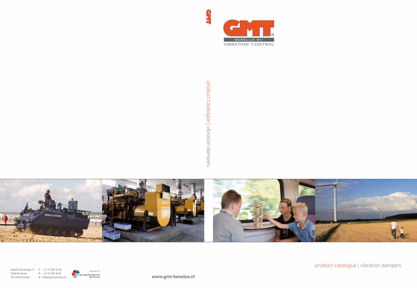
Customer specific solutionsGMT Benelux BV offers solutions for vibration control. We enhance comfort in work and life for people exposed to vibrations. By applying our solutions, production processes become more stable and wear is reduced. We add directly to the competitive advantage and sustainability of our customers. GMT is known for its three foundations: customer specific solutions, industry and application specific solutions and high quality standard solutions.
Industry specific solutionsFor many years GMT Benelux BV delivers industry specific and application specific solutions for vibration challenges. We offer a wide range of products for:• Machine builders;• Rail vehicles;• High tech industry;• Offshore & marine;• Aircraft industry;• Defence and vehicle industry.
Many products are developed in close cooperation with the OEM or are approved by the OEM partner. As an example we deliver solutions for Siemens rail vehicles, Airbus airplanes, and Leopard combat tanks. GMT Benelux BV can make use of the expertise, production and development of the German GMT Gummi-Metall-Technik GmbH.
Standard solutions GMT Benelux BV delivers a wide range of high quality standard products. The standard products are used in many applications like machine building. We offer vibration dampers in the most common sizes and quality. For applications in a humid environment we can also deliver a wide range of stainless steel products. Our standard products are delivered through technical trade companies (resellers) and via our own sales department directly to end-users. For most of the products we are able to deliver from local stock. We also offer logistical services such as delivery on demand, specific packing and assembly.
GMT Benelux BV offers solutions for vibration control. We enhance comfort in work and life for people exposed
to vibrations. By applying our solutions, production processes become more stable and wear is reduced. We add
directly to the competitive advantage and sustainability of our customers. GMT is known for its three foundations:
customer specific solutions, industry and application specific solutions and high quality standard solutions.
What will we do? What can you expect?
1 Analyze vibration issue We make an inventarisation of the application and environment. We will, amongst others, look at weight, frequencies and fulcrums.
Simple report with added calculations and ifpossible direct solution to the issue.
2 Measurements on location GMT Benelux will send a Certified VibrationAnalyst to execute measurements on location.
Vibration measurements are executed by well trained experts using stat-of-the-art hardware and software.
3 Analysis, reporting and consultation The measurement results are analysed,reported and conclusions and recommendation are added.
Extended report* with immediate insight ifissues are caused by insufficient isolation. Recommendation about most suitable solution.
* On request an example report can be forwarded.
4 Working towards a new solution If there is no standard solution to the issue we cab work with you towards new possibilities.
In rare occasion we need to look for new rubber compounds or designs. In such case you will finda project proposal.*
* Please see our application leaflet about high-end mechatronics.
GMT Benelux BV • 7 •• 6 • product catalogue | vibration dampers
Gen
eral
info
rmat
ion
Gen
eral
info
rmat
ion
test reports
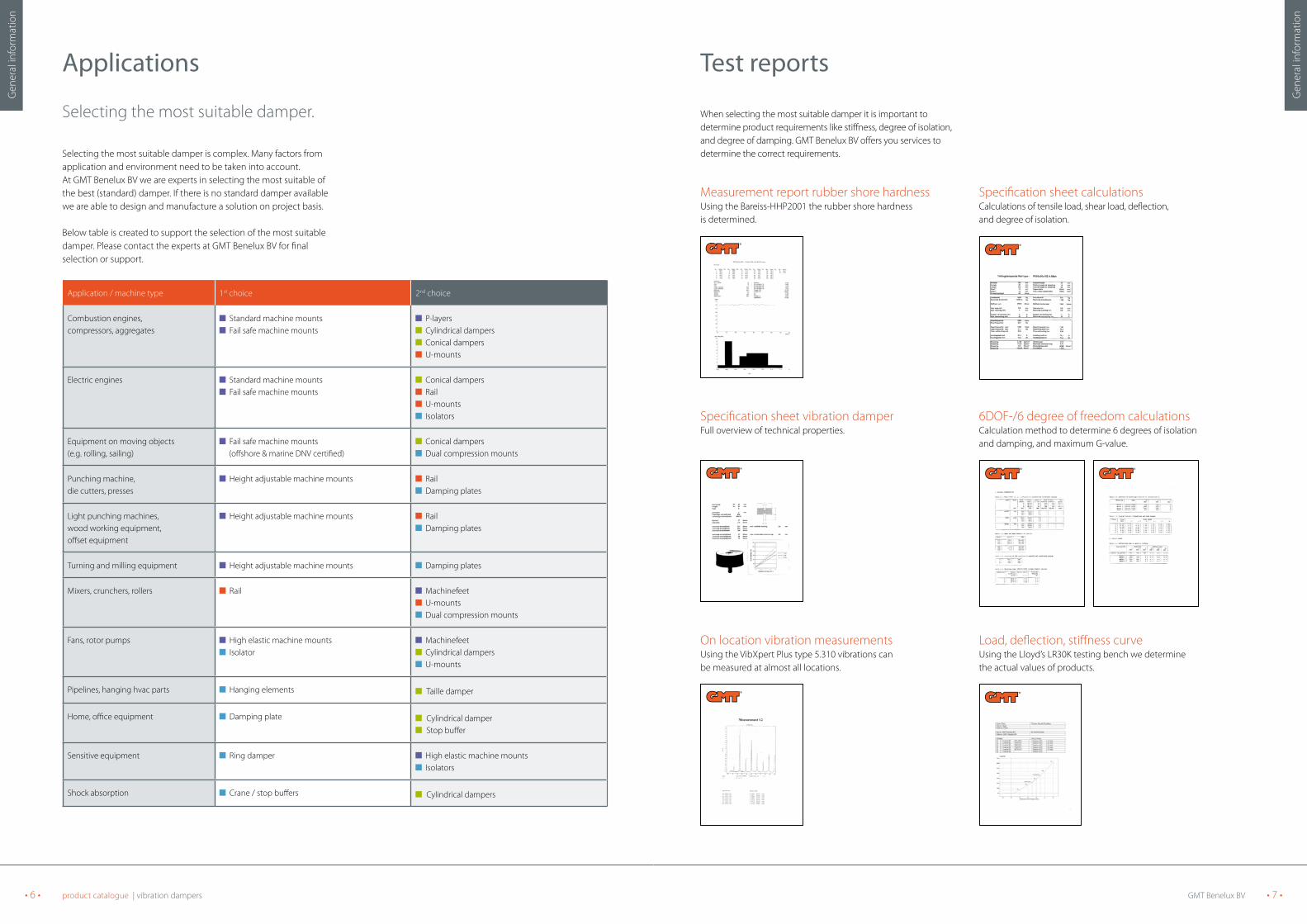
When selecting the most suitable damper it is important todetermine product requirements like stiffness, degree of isolation, and degree of damping. GMT Benelux BV offers you services todetermine the correct requirements.
Measurement report rubber shore hardness Specification sheet calculationsUsing the Bareiss-HHP2001 the rubber shore hardnessis determined.
Calculations of tensile load, shear load, deflection,and degree of isolation.
Specification sheet vibration damper 6DOF-/6 degree of freedom calculationsFull overview of technical properties. Calculation method to determine 6 degrees of isolation
and damping, and maximum G-value.
On location vibration measurements Load, deflection, stiffness curveUsing the VibXpert Plus type 5.310 vibrations can be measured at almost all locations.
Using the Lloyd’s LR30K testing bench we determinethe actual values of products.
Applications
Selecting the most suitable damper.
Selecting the most suitable damper is complex. Many factors from application and environment need to be taken into account. At GMT Benelux BV we are experts in selecting the most suitable of the best (standard) damper. If there is no standard damper available we are able to design and manufacture a solution on project basis.
Below table is created to support the selection of the most suitable damper. Please contact the experts at GMT Benelux BV for final selection or support.
Application / machine type 1st choice 2nd choice
Combustion engines, compressors, aggregates
Standard machine mounts Fail safe machine mounts
P-layers Cylindrical dampers Conical dampers U-mounts
Electric engines Standard machine mounts Fail safe machine mounts
Conical dampers Rail U-mounts Isolators
Equipment on moving objects (e.g. rolling, sailing)
Fail safe machine mounts (offshore & marine DNV certified)
Conical dampers Dual compression mounts
Punching machine, die cutters, presses
Height adjustable machine mounts Rail Damping plates
Light punching machines, wood working equipment, offset equipment
Height adjustable machine mounts Rail Damping plates
Turning and milling equipment Height adjustable machine mounts Damping plates
Mixers, crunchers, rollers Rail Machinefeet U-mounts Dual compression mounts
Fans, rotor pumps High elastic machine mounts Isolator
Machinefeet Cylindrical dampers U-mounts
Pipelines, hanging hvac parts Hanging elements Taille damper
Home, office equipment Damping plate Cylindrical damper Stop buffer
Sensitive equipment Ring damper High elastic machine mounts Isolators
Shock absorption Crane / stop buffers Cylindrical dampers

GMT Benelux BV • 9 •• 8 • product catalogue | vibration dampers
Gen
eral
info
rmat
ion
Gen
eral
info
rmat
ion
Table 1 Table 2Degree of isolation
(%)Frequency
ratio
0 1,41
20,0 1,5
35,9 1,6
47,1 1,7
55,4 1,8
61,7 1,9
66,7 2
74,0 2,2
79,0 2,4
82,6 2,6
85,4 2,8
87,5 3
89,2 3,2
90,5 3,4
91,6 3,6
92,6 3,8
93,3 4
94,0 4,2
94,6 4,4
95,0 4,6
95,5 4,8
95,8 5
96,2 5,2
96,4 5,4
96,7 5,6
96,9 5,8
97,1 6
97,3 6,2
97,5 6,4
97,7 6,6
97,8 6,8
97,9 7
98,0 7,2
98,1 7,4
98,2 7,6
98,3 7,8
98,4 8
98,5 8,2
98,6 8,4
98,6 8,6
98,7 8,8
98,8 9
98,8 9,2
98,9 9,4
98,9 9,6
98,9 9,8
99,0 10
Eigenfrequency Deflection(mm)Hz min-1
49,9 2991 0,1
35,3 2115 0,2
28,8 1727 0,3
24,9 1495 0,4
22,3 1338 0,5
20,4 1221 0,6
18,8 1130 0,7
17,6 1057 0,8
16,6 997 0,9
15,8 946 1
14,4 863 1,2
13,3 799 1,4
12,5 748 1,6
11,8 705 1,8
11,2 669 2
10,6 638 2,2
10,2 611 2,4
9,8 587 2,6
9,4 565 2,8
9,1 546 3
8,8 529 3,2
8,6 513 3,4
8,3 498 3,6
8,1 485 3,8
7,9 473 4
7,4 446 4,5
7,1 423 5
6,7 403 5,5
6,4 386 6
6,2 371 6,5
6,0 357 7
5,8 345 7,5
5,6 334 8
5,4 324 8,5
5,3 315 9
5,1 307 9,5
5,0 299 10
4,8 285 11
4,6 273 12
4,4 262 13
4,2 253 14
4,1 244 15
3,9 236 16
3,8 229 17
3,7 223 18
3,6 217 19
3,5 211 20
3,2 189 25
2,9 173 30
2,7 160 35
2,5 150 40
2,4 141 45
2,2 134 50
Determination of the most suitable damper
Please find below a calculation example to determine the requirementsfor the most suitable damper. Please let us know if we can support you?
Technical specifications:Total weight : 1200 kg.Number of fulcrums : 6.Frequency : 1440 min-1 = 24HzDesired degree of isolation : 80%.
Calculation:• 1200 kg = 200 kg (x9,81) = 1962 N per fulcrum. 6
• Frequency ratio for desired degree of isolation of 80% = 2,5 (see table 1)
• Eigenfrequency vibration damper = frequency frequency ratio
• Eigenfrequency = 1440 kg = 576 min -1 = 9,6 Hz 2,5
• Required deflection = 2,7 mm (see table 2).
Selecting the damper:• Select a vibration damper with a deflection of 2,7mm at a load of 1962N using the graphs.
• Select a vibration damper with a static stiffness (C) of 1962N = 727 N/mm using the table. 2,7mm
Never exceed the maximum deflection of the vibration damper!
Calculation example

GMT Benelux BV • 11 •• 10 • product catalogue | vibration dampers
Gen
eral
info
rmat
ion
Gen
eral
info
rmat
ion
* with special formulations onlyThe properties referred to above are given for guidance only- The properties indicated here areaffected by temperature, concentration etc. in specific applications and cannot be guaranteed.
Missing details upon request. No guarantee for correctness of technical dates. Accordingly we reserve the right to alter, amend or withdraw any product without notice.
Rubber quality list
Commercial name Acrylic rubber
Good resistance to high temperatures and mineral oils, high resistance to oxygen and ozone, unfavourable low-temperature properties.
Polyboron rubber
High mechanical strength, good resistance ozone, medium resistance to oil, flexibility/ damping property can be varied as required, excellent resistance to water, slight permanent set.
Epichlorohydrin rubber
Low gaspermeability,very goodlow-temperatureproperties, goodresistance tomineral oils,ozone and high temperatures.
Butyl rubber
Very slightlypermeable to air, steam and other gases, good resistance to heat, oxygen, ozone and many chemicals and solvents, good electrical properties (isolating), goodresistance to abrasion an tear propagation.
Hydrogenated NBR
High resistance to heat, ozone and oil, good mechanical propertiesalso at hightemperatures, excellentresistance to wear and tear.
Natural rubber
Characterized by flexibility, strength hand low-temperature resistance as well as excellent physicalproperties ideal for bonded rubber/metal elements.Not suitable for petrol, grease, oils and ozone.
PerbunanAcrylonitrilebutadiene rubber
Highly resistant to abrasionand tearing, particularlyresistant to ageing.Particularly recommended for crude oil products, high temperatures, heating and lubricating oils, petrol andparaffin oil.
NeopreneChloroprene rubber
All-purpose synthetic rubber, flame resistant, resistant toabrasion, very robust, gooddielectric strength,particularly recommended for exposure to ozone and weathering.
SBRStyrene butadiene rubber
Similar to natural rubber, resistantto abrasion,rubbing in, good resistance to hightemperatures and cracking, resistance to extreme lowtemperatures, not resistant to petrol, benzene, greases and oils.
Polyurethane
Excellentresistance to wear and tear, best flexibility with high shore hardness of all the elastomers,good resistanceto oil, not resistant to hydrolysis.
Silicone rubber
Resistant to high temperatures, odourless and tasteless, nontoxic, can be sterilized in accordance with foodstuffs regula-tions, resistant tosea water andcorrosive saltsolutions, not to be used in conjunction with steam, con-centrated acids and lyes, swells strongly under the effect of aromatic solvents.
APTK rubberEPDM Ethylene-propylenediene-rubberVersatile in use,very good flexibility,resistant to abrasion, resistant to wear and tear, resistant to ozone and weather, resistant to low temperatures, can be used to protect against washing and spraying agents, excellent for profile cords, not usable in conjunction with petrol, solvents and mineral oils.
Hypalon Chiorosul-phonated polyethylene
Fast to light,colour-fast,flame-resistant, good dielectric strength,particularlyrecommended for exposure to sunlight, ozone, weather andoxidizing, chemicals, however, it has a very low tensile strength.
VitonFluorinated rubber
Hexafluoropropy-lene vinylidene, fluoride copolymer, Resistant to extreme temperatures even over 200 C. Very good mechanical properties and high resistance to tearing event at high tem-peratures. Excellent for exposure to sunlight, ozone and weather. Not recom-mended for use in conjunction with esters and ketones.
International designation ACM PNR ECO IIR HNBR NR NBR CR SBR PUR MVQ/SI EPDM/EPM CSM FPM
Hardness available 50-80 Shore A 10-80 Shore A 50-90 Shore A 40-80 Shore A 40-90 Shore A 25-95 Shore A 25-90 Shore A 30-90 Shore A 35-93 Shore A 55-98 Shore A 40-80 Shore A 30-90 Shore A 50-95 Shore A 65-90 Shore
Resistance to temperatures -35°C tot +175°C -40°C tot +80°C -40°C tot +130°C -40°C tot +130°C -40°C tot +175°C -40°C tot +80°C -40°C tot +140°C -30°C tot +90°C -30°C tot +110°C -30°C tot +80°C -70°C tot +180°C -40°C tot +150°C -40°C tot +120°C -30°C tot +225°C
Short-time peak temperature +220°C +100°C +150°C +150°C +200°C +100°C +160°C +150°C +150°C +100°C +225°C +180°C +175°C +350°C
Tensile strength in kp/sq. cm (N/sq. mm) 160 (16) 170 (17) 170 (17) 170 (17) 300 (30) 250 (25) 250 (25) 250 (25) 250 (25) 300 (30) 80 (8) 200 (20) 180 (18) 200 (20)
Tensile elongation in % 350% 700% 500 % 800% 600% 800% 500% 450% 450% 800% 250% 450% 300% 400%
Properties
Abrasion moderate good moderate good very good good very good good very good excellent moderate good moderate good
Resistance to flex cracking moderate moderate good moderate very good good moderate very good good - bad very good good good
Elongation/tensile strength good good good good very good excellent good good good excellent bad good good good
Flexibility low as required moderate low good excellent good good good good good good good moderate
Notch strength/strength of structure - moderate good good good good excellent good good excellent moderate moderate good almost good
Resistance to light good good good very good good bad bad very good moderate good excellent excellent excellent excellent
Resistance to oxidizing very good good good very good good good moderate good moderate good very good excellent excellent excellent
Resistance to ozone very good good very good very good good moderate moderate very good moderate good excellent excellent excellent excellent
Resistance to wear and tear good good - good good good very good very good very good excellent bad good good almost good
Weathering effect very good good good very good good good moderate very good good moderate excellent excellent excellent excellent
Resistance to
Lyes not suitable moderate bad very good good good good very good good not suitable not suitable excellent very good very good
Petrol not suitable not suitable good not suitable good not suitable excellent moderate not suitable very good not suitable not suitable moderate excellent
Benzole not suitable not suitable good not suitable moderate not suitable bad not suitable not suitable not suitable not suitable not suitable not suitable good
Foodstuffs* not suitable not suitable not suitable suitable not suitable suitable suitable suitable suitable not suitable excellent suitable suitable not suitable
Solvents, aliphatic bad not suitable good not suitable very good not suitable very good moderate not suitable very good not suitable bad moderate very good
Solvents, aromatic bad not suitable good not suitable conditional not suitable conditional moderate not suitable moderate not suitable not suitable moderate good
Solvents, halogene bad not suitable not suitable not suitable conditional not suitable bad bad not suitable bad not suitable not suitable moderate good
Oils and greases very good conditional very good not suitable very good not suitable excellent good not suitable very good good bad good good
Acids not suitable moderate moderate very good moderate (conditional) conditional conditional good conditional not suitable not suitable very good very good very good
Water good excellent moderate good very good good good very good very good not suitable good very good good good
GMT Benelux BV • 13 •• 12 • product catalogue | machine mounts
Mac
hine
mou
nts
Mac
hine
mou
nts
Machine mounts standard
H
Fz
LsL
MKD
B
d
Fy
Fx
Load Fz
1 2 3 4 50
1
2
4
5
67
3
70°Sh A
55°Sh A
40°Sh A
de�ection (mm)
forc
e (k
N)
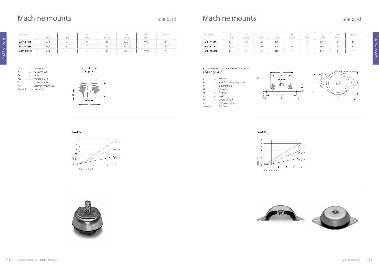
On request this machine mount is optional height adjustable
L = lengthLs = spacing mounting holesK = diameter lidD = diameterH = heightB = widthM = screw threadd = bore diameterShore A = hardness
Art.Code L(mm)
Ls(mm)
K(mm)
D(mm)
H(mm)
B(mm)
M(mm)
d(mm)
Shore A
6001203143 170 140 90 106 39 110 M12i 13 40°
6001203157 170 140 90 106 39 110 M12i 13 55°
6001203168 170 140 90 106 39 110 M12i 13 70°
Load Fz
D = diameterK = diameter lidH = heightH1 = thread depthM = screw threadMi = internal thread sizeShore A = hardness
Art.Code D(mm)
K(mm)
H(mm)
H1(mm)
M(mm)
Mi(mm)
Shore A
6001003043 55,3 41 41 14 10 x 21,5 M10i 40°
6001003057 55,3 41 41 14 10 x 21,5 M10i 55°
6001003068 55,3 41 41 14 10 x 21,5 M10i 70°
Machine mounts standard
H
M
K
Mi
H1
D
1 2 3 4 50
0,4
0,8
1,6
2
1,2
70°Sh A
55°Sh A
40°Sh A
de�ection (mm)
forc
e (k
N)
load FzLoad Fz

GMT Benelux BV • 15 •• 14 • product catalogue | machine mounts
Mac
hine
mou
nts
Mac
hine
mou
nts
Machine mounts standard
On request this machine mount is optional height adjustable
L = lengthLs = spacing mounting holesK = diameter lidD = diameterH = heightB = widthM = screw threadd = bore diameterShore A = hardness
Art.Code L(mm)
Ls(mm)
K(mm)
D(mm)
H(mm)
B(mm)
M(mm)
d(mm)
Shore A
6001703343 220 180 110 150 51,5 150 M20i 16,5 40°
6001703357 220 180 110 150 51,5 150 M20i 16,5 55°
6001703368 220 180 110 150 51,5 150 M20i 16,5 70°
H
MKD
Fz
LsL
B
d
Fy
Fx
Load Fz
1 2 3 4 5024
8101214
16
6
70°Sh A
55°Sh A
40°Sh A
de�ection (mm)
forc
e (k
N)
Load Fz
On request this machine mount is optional height adjustable
L = lengthLs = spacing mounting holesK = diameter lidD = diameterH = heightB = widthM = screw threadd = bore diameterShore A = hardness
Art.Code L(mm)
Ls(mm)
K(mm)
D(mm)
H(mm)
B(mm)
M(mm)
d(mm)
Shore A
6001603243 168 132 113 150 51,5 168 M16i 12,5 40°
6001603257 168 132 113 150 51,5 168 M16i 12,5 55°
6001603268 168 132 113 150 51,5 168 M16i 12,5 70°
Machine mounts standard
H
Fz MKD
L
B
d
Ls
Fy
Fx
Load Fz
1 2 3 4 5024
8101214
16
6
70°Sh A
55°Sh A
40°Sh A
de�ection (mm)
forc
e (k
N)
Load Fz
GMT Benelux BV • 17 •• 16 • product catalogue | machine mounts
Mac
hine
mou
nts
Mac
hine
mou
nts
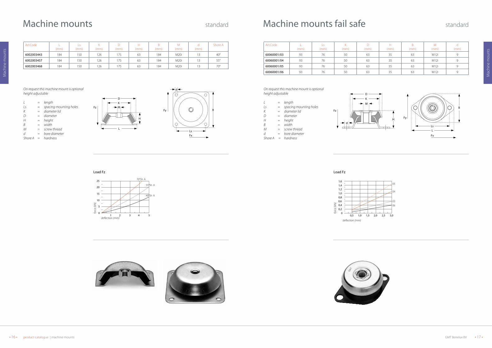
On request this machine mount is optional height adjustable
L = lengthLs = spacing mounting holesK = diameter lidD = diameterH = heightB = widthM = screw threadd = bore diameterShore A = hardness
Art.Code L(mm)
Ls(mm)
K(mm)
D(mm)
H(mm)
B(mm)
M(mm)
d(mm)
60060001/03 93 76 50 63 35 63 M12i 9
60060001/04 93 76 50 63 35 63 M12i 9
60060001/05 93 76 50 63 35 63 M12i 9
60060001/06 93 76 50 63 35 63 M12i 9
Machine mounts fail safe standard
H
M
d
K
D
FzB
Fy
Fx
LLs
0,5 1,0 1,5 2,0 2,5 3,00
0,20,4
0,81,01,21,41,6
0,6
05
04
03
06
de�ection (mm)
forc
e (k
N)
Load FzLoad Fz
On request this machine mount is optional height adjustable
L = lengthLs = spacing mounting holesK = diameter lidD = diameterH = heightB = widthM = screw threadd = bore diameterShore A = hardness
Art.Code L(mm)
Ls(mm)
K(mm)
D(mm)
H(mm)
B(mm)
M(mm)
d(mm)
Shore A
6002003443 184 150 126 175 63 184 M20i 13 40°
6002003457 184 150 126 175 63 184 M20i 13 55°
6002003468 184 150 126 175 63 184 M20i 13 70°
Machine mounts standard
H
MKD
Fz
L
B
d
Fy
FxLs
Load Fz
1 2 3 4 50
5
10
20
25
15
70°Sh A
55°Sh A
40°Sh A
de�ection (mm)
forc
e (k
N)
Load Fz

GMT Benelux BV • 19 •• 18 • product catalogue | machine mounts
Mac
hine
mou
nts
Mac
hine
mou
nts
Machine mounts fail safe standard
Art.Code L(mm)
Ls(mm)
K(mm)
D(mm)
H(mm)
B(mm)
M(mm)
d(mm)
Shore A
6001640S 168 132 113 150 51,5 168 M16i 13 40°
6001655S 168 132 113 150 51,5 168 M16i 13 55°
6001670S 168 132 113 150 51,5 168 M16i 13 70°
On request this machine mount is optional height adjustable
L = lengthLs = spacing mounting holesK = diameter lidD = diameterH = heightB = widthM = screw threadd = bore diameterShore A = hardness
H
L
MKD
FzB
d
Ls
Fy
Fx
1 2 3 4 5024
810121416
6
70°Sh A
55°Sh A
40°Sh A
de�ection (mm)
forc
e (k
N)
Load FzLoad Fz
On request this machine mount is optional height adjustable
L = lengthLs = spacing mounting holesK = diameter lidD = diameterH = heightB = widthM = screw threadd = bore diameterShore A = hardness
Art.Code L(mm)
Ls(mm)
K(mm)
D(mm)
H(mm)
B(mm)
M(mm)
d(mm)
Shore A
6001240S 170 140 90 106 39 110 M12i 13 40°
6001255S 170 140 90 106 39 110 M12i 13 55°
6001270S 170 140 90 106 39 110 M12i 13 70°
Machine mounts fail safe standard
H
LsL
MKD
Fz
B
d
Fy
Fx
1 2 3 4 650
1
2
4
5
6
3
70°Sh A
55°Sh A
40°Sh A
de�ection (mm)
forc
e (k
N)
Load FzLoad Fz

GMT Benelux BV • 21 •• 20 • product catalogue | machine mounts
Mac
hine
mou
nts
Mac
hine
mou
nts
On request this machine mount is optional height adjustable
L = lengthLs = spacing mounting holesK = diameter lidD = diameterH = heightB = widthM = screw threadd = bore diameterShore A = hardness
Art.Code L(mm)
Ls(mm)
K(mm)
D(mm)
H(mm)
B(mm)
M(mm)
d(mm)
Shore A
6007740S 128 110 59 77 30 77 M10i 9 40°
6007750S 128 110 59 77 30 77 M10i 9 50°
6007760S 128 110 59 77 30 77 M10i 9 60°
6007770S 128 110 59 75 30 77 M10i 9 70°
Machine mounts fail safe DNV certified
H
LsL
MKD
Fz
B
d
1 2 3 4 650
1
2
4
5
6
3
70°Sh A
60°Sh A
50°Sh A
40°Sh A
deflection (mm)
forc
e (k
N)
Load FzLoad Fz
On request this machine mount is optional height adjustable
L = lengthLs = spacing mounting holesK = diameter lidD = diameterH = heightB = widthM = screw threadd = bore diameterShore A = hardness
Art.Code L(mm)
Ls(mm)
K(mm)
D(mm)
H(mm)
B(mm)
M(mm)
d(mm)
Shore A
6002043S 184 150 126 175 63 184 M20i 13 40°
6002057S 184 150 126 175 63 184 M20i 13 55°
6002068S 184 150 126 175 63 184 M20i 13 70°
Machine mounts fail safe standard
H
L
MKD
FzB
d
Fy
FxLs
1 2 3 4 50
5
10
20
25
15
70°Sh A
55°Sh A
40°Sh A
deflection (mm)
forc
e (k
N)
Load FzLoad Fz

GMT Benelux BV • 23 •• 22 • product catalogue | machine mounts
Mac
hine
mou
nts
Mac
hine
mou
nts
Art.Code L(mm)
Ls(mm)
K(mm)
D(mm)
H(mm)
B(mm)
M(mm)
d(mm)
Shore A
6010840S 172 144 82 108 38 108 M16i 13,5 40°
6010850S 172 144 82 108 38 108 M16i 13,5 50°
6010860S 172 144 82 108 38 108 M16i 13,5 60°
6010870S 172 144 82 108 38 108 M16i 13,5 70°
Machine mounts fail safe DNV certified
On request this machine mount is optional height adjustable
L = lengthLs = spacing mounting holesK = diameter lidD = diameterH = heightB = widthM = screw threadd = bore diameterShore A = hardness
H
LsL
MKD
Fzd
B
Load Fz
1 2 3 4 65012
4
5678
3
70°Sh A
60°Sh A
50°Sh A
40°Sh A
deflection (mm)
forc
e (k
N)
Load Fz
Machine mounts fail safe DNV certified
Art.Code L(mm)
Ls(mm)
K(mm)
D(mm)
H(mm)
B(mm)
M(mm)
d(mm)
Shore A
6009440S 144 124 70 94 35 94 M10i 10 40°
6009450S 144 124 70 94 35 94 M10i 10 50°
6009460S 144 124 70 94 35 94 M10i 10 60°
6009470S 144 124 70 94 35 94 M10i 10 70°
On request this machine mount is optional height adjustable
L = lengthLs = spacing mounting holesK = diameter lidD = diameterH = heightB = widthM = screw threadd = bore diameterShore A = hardness
Fz
LsL
H
MKD
B
d
Load Fz
1 2 3 4 65012
4567
98
3
70°Sh A
60°Sh A
50°Sh A
40°Sh A
deflection (mm)
forc
e (k
N)
Load Fz
GMT Benelux BV • 25 •• 24 • product catalogue | machine mounts
Mac
hine
mou
nts
Mac
hine
mou
nts
Art.Code L(mm)
Ls(mm)
K(mm)
D(mm)
H(mm)
B(mm)
M(mm)
d(mm)
Shore A
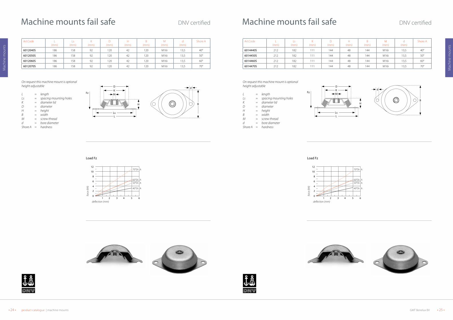
6014440S 212 182 111 144 48 144 M16i 13,5 40°
6014450S 212 182 111 144 48 144 M16i 13,5 50°
6014460S 212 182 111 144 48 144 M16i 13,5 60°
6014470S 212 182 111 144 48 144 M16i 13,5 70°
Machine mounts fail safe DNV certified
On request this machine mount is optional height adjustable
L = lengthLs = spacing mounting holesK = diameter lidD = diameterH = heightB = widthM = screw threadd = bore diameterShore A = hardness
LsL
H
Fz MKD
B
d
Load Fz
1 2 3 4 650
2
4
8
10
12
6
70°Sh A
60°Sh A50°Sh A
40°Sh A
deflection (mm)
forc
e (k
N)
Load Fz
Art.Code L(mm)
Ls(mm)
K(mm)
D(mm)
H(mm)
B(mm)
M(mm)
d(mm)
Shore A
6012040S 186 158 92 120 42 120 M16i 13,5 40°
6012050S 186 158 92 120 42 120 M16i 13,5 50°
6012060S 186 158 92 120 42 120 M16i 13,5 60°
6012070S 186 158 92 120 42 120 M16i 13,5 70°
Machine mounts fail safe DNV certified
On request this machine mount is optional height adjustable
L = lengthLs = spacing mounting holesK = diameter lidD = diameterH = heightB = widthM = screw threadd = bore diameterShore A = hardness
H
LsL
MKD
Fz
B
d
Load Fz
1 2 3 4 650
2
4
8
10
12
6
70°Sh A
60°Sh A50°Sh A
40°Sh A
deflection (mm)
forc
e (k
N)
Load Fz
GMT Benelux BV • 27 •• 26 • product catalogue | machine mounts
Mac
hine
mou
nts
Mac
hine
mou
nts
Art.Code L(mm)
Ls(mm)
K(mm)
H(mm)
B(mm)
BS(mm)
M(mm)
d1(mm)
d2(mm)
Sh A
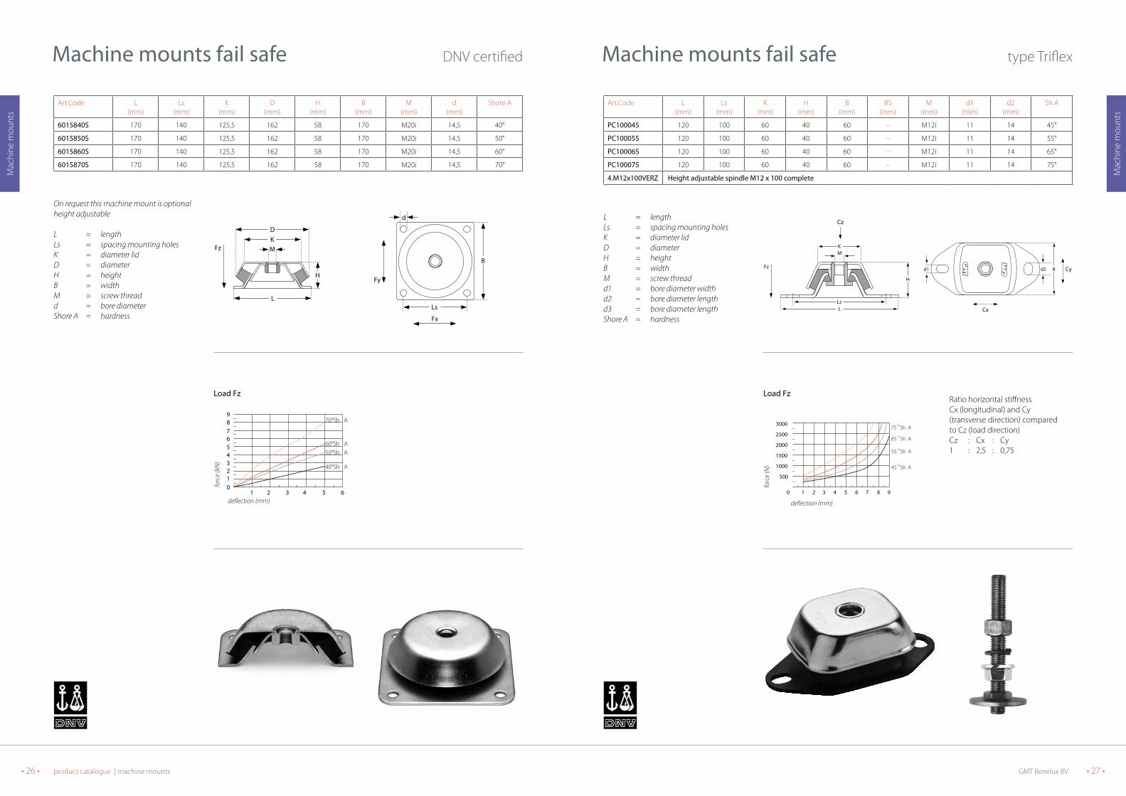
PC100045 120 100 60 40 60 - M12i 11 14 45°
PC100055 120 100 60 40 60 - M12i 11 14 55°
PC100065 120 100 60 40 60 - M12i 11 14 65°
PC100075 120 100 60 40 60 - M12i 11 14 75°
4.M12x100VERZ Height adjustable spindle M12 x 100 complete
Machine mounts fail safe type Triflex
L = lengthLs = spacing mounting holesK = diameter lidD = diameterH = heightB = widthM = screw threadd1 = bore diameter widthd2 = bore diameter lengthd3 = bore diameter lengthShore A = hardness
Ratio horizontal stiffnessCx (longitudinal) and Cy(transverse direction) comparedto Cz (load direction)Cz : Cx : Cy1 : 2,5 : 0,75
MK
LsL
H
Fz
Cz
d1 B d2 Cy
Cx
1 2 3 6 5 4 7 8 9 0
500
1000
1500
2000
2500
3000
45 °Sh A
55 °Sh A
75 °Sh A
65 °Sh A
Load Fz
forc
e (N
)
deflection (mm)
Load Fz
Art.Code L(mm)
Ls(mm)
K(mm)
D(mm)
H(mm)
B(mm)
M(mm)
d(mm)
Shore A
6015840S 170 140 125,5 162 58 170 M20i 14,5 40°
6015850S 170 140 125,5 162 58 170 M20i 14,5 50°
6015860S 170 140 125,5 162 58 170 M20i 14,5 60°
6015870S 170 140 125,5 162 58 170 M20i 14,5 70°
Machine mounts fail safe DNV certified
On request this machine mount is optional height adjustable
L = lengthLs = spacing mounting holesK = diameter lidD = diameterH = heightB = widthM = screw threadd = bore diameterShore A = hardness
H
L
MKD
Fz
B
d
Ls
Fy
Fx
Load Fz
1 2 3 4 65012
4567
98
3
70°Sh A
60°Sh A50°Sh A
40°Sh A
deflection (mm)
forc
e (k
N)
Load Fz

GMT Benelux BV • 29 •• 28 • product catalogue | machine mounts
Mac
hine
mou
nts
Mac
hine
mou
nts
Machine mounts fail safe type Triflex
Art.Code L(mm)
Ls(mm)
K(mm)
H(mm)
B(mm)
BS(mm)
M(mm)
d1(mm)
d2(mm)
d3(mm)
Sh A
PC182045 230 182 112 70 112 - M20i 18 26 34 45°
PC182055 230 182 112 70 112 - M20i 18 26 34 55°
PC182065 230 182 112 70 112 - M20i 18 26 34 65°
PC182075 230 182 112 70 112 - M20i 18 26 34 75°
4M20x150VERZ Height adjustable spindle M20 x 150 complete
L = lengthLs = spacing mounting holesK = diameter lidD = diameterH = heightB = widthM = screw threadd1 = bore diameter widthd2 = bore diameter lengthd3 = bore diameter lengthShore A = hardness
Ratio horizontal stiffnessCx (longitudinal) and Cy(transverse direction) comparedto Cz (load direction)Cz : Cx : Cy1 : 2,6 : 0,85
M K
LsL
H
Fz
Cz
d1 d2
d3 B Cy
Cx
1 2 3 6 5 4 7 8 9 0
4
8
12
16
20
2 4
45 °Sh A
55 °Sh A
75 °Sh A
65 °Sh A
Load Fz
forc
e (k
N)
deflection (mm)
Load Fz
Machine mounts fail safe type Triflex
Art.Code L(mm)
Ls(mm)
K(mm)
H(mm)
B(mm)
BS(mm)
M(mm)
d1(mm)
d2(mm)
d3(mm)
Sh A
PC140045 184 140 75 50 75 - M16i 13 20 30 45°
PC140055 184 140 75 50 75 - M16i 13 20 30 55°
PC140065 184 140 75 50 75 - M16i 13 20 30 65°
PC140075 184 140 75 50 75 - M16i 13 20 30 75°
4M16x110VERZ Height adjustable spindle M16 x 110 complete
L = lengthLs = spacing mounting holesK = diameter lidD = diameterH = heightB = widthM = screw threadd1 = bore diameter widthd2 = bore diameter lengthd3 = bore diameter lengthShore A = hardness
Ratio horizontal stiffnessCx (longitudinal) and Cy(transverse direction) comparedto Cz (load direction)Cz : Cx : Cy1 : 2,7 : 0,7
M
K
LsL
H
Fz
Cz
d2d1
d3 B Cy
Cx
1 2 3 6 5 4 7 8 9 0
2
4
6
8
10
45 °Sh A
55 °Sh A
75 °Sh A65 °Sh A
deflection (mm)
forc
e (k
N)
Load FzLoad Fz

GMT Benelux BV • 31 •• 30 • product catalogue | machine mounts
Mac
hine
mou
nts
Mac
hine
mou
nts
The graph represents the deflection of the damper when the load is applied vertically. The horizontal stiffness’s as ratio of thevertical stiffness’s are:
Type Cz : Cx : Cy60.213 1 : 0,25 : 2,560.213HD 1 : 0,30 : 1,7
Cz = load directionCx = longitudinal directionCy = transverse direction
Combimounts Triflex
Artikel-Nr A(mm)
B(mm)
H(mm)
L(mm)
Ls(mm)
F(mm)
d(mm)
M(mm)
60213 230 204 110 205 165 148 18 M16i
60213HD 230 204 125 205 165 148 18 M16i
LsL
A
Cz
Cx
Type 60.213
H
B
M
d
F
Fz
Cy
H
B
M
d
F
Fz
Type 60.213HD
H
M
d
F
B
Fz
Cy
1 2 3 4 5 6 7 80
5
10
20
25
15
60ºShA
55ºShA45ºSh A
70ºShA
80ºShA
Load Fz type 60.213
forc
e (k
N)
defelction (mm)
2 4 6 8 10 12 14 1602
14
18
10
6
60º Sh A
45º Sh A
50º Sh A55º Sh A
70º Sh A
65º Sh A
Load Fz type 60.213HD
forc
e (k
N)
deflection (mm)
Load Fz type 60.213
type 60.213
Load Fz type 60.213HD
type 60.213HD
Machine mounts fail safe type Triflex
Art.Code L(mm)
Ls(mm)
K(mm)
H(mm)
B(mm)
BS(mm)
M(mm)
d(mm)
Sh A
PC270045 330 270 221 111 190 135 M24i 22 45°
PC270055 330 270 221 111 190 135 M24i 22 55°
PC270065 330 270 221 111 190 135 M24i 22 65°
L = lengthLs = spacing mounting holesK = diameter lidD = diameterH = heightB = widthM = screw threadd1 = bore diameter widthd2 = bore diameter lengthd3 = bore diameter lengthShore A = hardness
Ratio horizontal stiffnessCx (longitudinal) and Cy(transverse direction) comparedto Cz (load direction)Cz : Cx : Cy1 : 2,3 : 0,6
M
H
K
LsL
Fz
d d
B BS
1 2 3 4 5 6 7 8 0
5
10
15
20
25
30
35
45 °Sh A
55 °Sh A
65 °Sh A
forc
e (k
N)
Load Fz

GMT Benelux BV • 33 •• 32 • product catalogue | machine mounts
Mac
hine
mou
nts
Mac
hine
mou
nts
Art.Code L(mm)
Ls(mm)
D(mm)
d(mm)
M(mm)
H(mm)
h(mm)
IS6010040 60 49,5 58 5,2 M6i 28 18
IS6010050 60 49,5 58 5,2 M6i 28 18
IS6010060 60 49,5 58 5,2 M6i 28 18
IS6010070 60 49,5 58 5,2 M6i 28 18
IS6010140 77 61 58 9 M8i 28 18
IS6010150 77 61 58 9 M8i 28 18
IS6010160 77 61 58 9 M8i 28 18
IS6010170 77 61 58 9 M8i 28 18
Machine mounts fail safe type IS
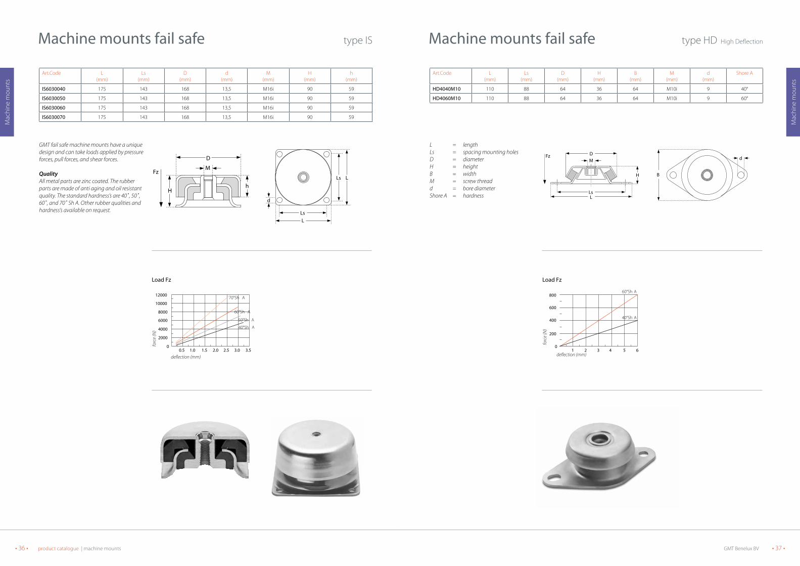
GMT fail safe machine mounts have a unique design and can take loads applied by pressure forces, pull forces, and shear forces.
QualityAll metal parts are zinc coated. The rubber parts are made of anti aging and oil resistant quality. The standard hardness’s are 40˚, 50˚, 60˚, and 70˚ Sh A. Other rubber qualities and hardness’s available on request.
hH
M
D
Fz
LsL
d
Ls L
1.00.5 2.01.5 3.02.5 3.50
200
400
800
1200
1000
600
70°Sh A 60°Sh A
50°Sh A
40°Sh A
deflection (mm)
forc
e (N
)
Load FzLoad Fz
L = lengthB = widthH = heightb = widthLs = spacing mounting holesd = diameter mounting holess = plate thicknessM = screw thread
Material: natural rubber
Standard stock keeping units
Art.Code L(mm)
B(mm)
H(mm)
b(mm)
Ls(mm)
d(mm)
s(mm)
M(mm)
PS5140 170 127 43 60 146 10,3 5,0 m 8 x 15
PS5150 170 127 43 60 146 10,3 5,0 m 8 x 15
PS5160 170 127 43 60 146 10,3 5,0 m 8 x 15
PS5170 170 127 43 60 146 10,3 5,0 m 8 x 15
Sandwich elements
Ls b
L
H
s
dB
Pres
sure
load
(kN
)
deflection (mm)
10
2
4
6
8
10
12
2 3 4
type PS51
type PS51

GMT Benelux BV • 35 •• 34 • product catalogue | machine mounts
Mac
hine
mou
nts
Mac
hine
mou
nts
Art.Code L(mm)
Ls(mm)
D(mm)
d(mm)
M(mm)
H(mm)
h(mm)
IS6040040 133 108 124 11,9 M16i 63 38
IS6040050 133 108 124 11,9 M16i 63 38
IS6040060 133 108 124 11,9 M16i 63 38
IS6040070 133 108 124 11,9 M16i 63 38
Machine mounts fail safe type IS
GMT fail safe machine mounts have a unique design and can take loads applied by pressure forces, pull forces, and shear forces.
QualityAll metal parts are zinc coated. The rubber parts are made of anti aging and oil resistant quality. The standard hardness’s are 40˚, 50˚, 60˚, and 70˚ Sh A. Other rubber qualities and hardness’s available on request.
Hh
M
D
Fz LsL
LsL
d
1.00.5 2.01.5 3.0 3.52.50
1000
2000
4000
6000
5000
3000
70°Sh A60°Sh A
50°Sh A40°Sh A
deflection (mm)
forc
e (N
)
Load FzLoad Fz
Art.Code L(mm)
Ls(mm)
D(mm)
d(mm)
M(mm)
H(mm)
h(mm)
IS6020040 76 63,5 76 6,4 M10i 38 25
IS6020050 76 63,5 76 6,4 M10i 38 25
IS6020060 76 63,5 76 6,4 M10i 38 25
IS6020070 76 63,5 76 6,4 M10i 38 25
IS6020140 90 74 76 9 M12i 38 25
IS6020150 90 74 76 9 M12i 38 25
IS6020160 90 74 76 9 M12i 38 25
IS6020170 90 74 76 9 M12i 38 25
Machine mounts fail safe type IS
GMT fail safe machine mounts have a unique design and can take loads applied by pressure forces, pull forces, and shear forces.
QualityAll metal parts are zinc coated. The rubber parts are made of anti aging and oil resistant quality. The standard hardness’s are 40˚, 50˚, 60˚, and 70˚ Sh A. Other rubber qualities and hardness’s available on request.
hH
M
D
Fz
LsL
d
Ls L
1.00.5 2.01.5 3.02.50
500
1000
2000
2500
1500
70°Sh A
60°Sh A
50°Sh A
40°Sh A
deflection (mm)
forc
e (N
)
Load Fz
38
Load Fz
GMT Benelux BV • 37 •• 36 • product catalogue | machine mounts
Mac
hine
mou
nts
Mac
hine
mou
nts
Art.Code L(mm)
Ls(mm)
D(mm)
H(mm)
B(mm)
M(mm)
d(mm)
Shore A
HD4040M10 110 88 64 36 64 M10i 9 40°
HD4060M10 110 88 64 36 64 M10i 9 60°
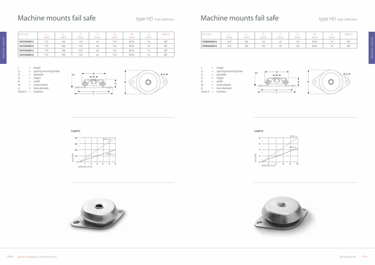
Machine mounts fail safe type HD High Deflection
L = lengthLs = spacing mounting holesD = diameterH = heightB = widthM = screw threadd = bore diameterShore A = hardness
LsL
DM
H
Fz
B
d
21 43 650
200
400
800
600
60°Sh A
40°Sh A
deflection (mm)
forc
e (N
)
Load FzLoad Fz
Art.Code L(mm)
Ls(mm)
D(mm)
d(mm)
M(mm)
H(mm)
h(mm)
IS6030040 175 143 168 13,5 M16i 90 59
IS6030050 175 143 168 13,5 M16i 90 59
IS6030060 175 143 168 13,5 M16i 90 59
IS6030070 175 143 168 13,5 M16i 90 59
Machine mounts fail safe type IS
GMT fail safe machine mounts have a unique design and can take loads applied by pressure forces, pull forces, and shear forces.
QualityAll metal parts are zinc coated. The rubber parts are made of anti aging and oil resistant quality. The standard hardness’s are 40˚, 50˚, 60˚, and 70˚ Sh A. Other rubber qualities and hardness’s available on request.
hH
M
D
Fz
LsL
d
Ls L
1.00.5 2.01.5 3.0 3.52.50
2000
4000
8000
12000
10000
6000
70°Sh A
60°Sh A
50°Sh A
40°Sh A
deflection (mm)
forc
e (N
)
Load FzLoad Fz

GMT Benelux BV • 39 •• 38 • product catalogue | machine mounts
Mac
hine
mou
nts
Mac
hine
mou
nts
Art.Code L(mm)
Ls(mm)
D(mm)
H(mm)
B(mm)
M(mm)
d(mm)
Shore A
HD12540M12 135 110 84 36 84 M12i 11 40°
HD12560M12 135 110 84 36 84 M12i 11 60°
Machine mounts fail safe type HD High Deflection
L = lengthLs = spacing mounting holesD = diameterH = heightB = widthM = screw threadd = bore diameterShore A = hardness
LsL
DM
H
Fz
B
d
21 43 650
800
1200
1600
3000
400
60°Sh A
40°Sh A
deflection (mm)
forc
e (N
)
Load FzLoad Fz
Art.Code L(mm)
Ls(mm)
D(mm)
H(mm)
B(mm)
M(mm)
d(mm)
Shore A
HD6040M12 120 100 64 36 64 M12i 11 40°
HD6060M12 120 100 64 36 64 M12i 11 60°
Machine mounts fail safe type HD High Deflection
L = lengthLs = spacing mounting holesD = diameterH = heightB = widthM = screw threadd = bore diameterShore A = hardness Ls
L
DM
H
Fz
B
d
21 43 650
0,5
1,0
2,0
1,5
60°Sh A
40°Sh A
deflection (mm)
forc
e (k
N)
Load FzLoad Fz
GMT Benelux BV • 41 •• 40 • product catalogue | machine mounts
Mac
hine
mou
nts
Mac
hine
mou
nts
Art.Code L(mm)
Ls(mm)
D(mm)
H(mm)
B(mm)
M(mm)
d(mm)
Shore A
HD80040M16 216 182 155 55 155 M16i 14 40°
HD80060M16 216 182 155 55 155 M16i 14 60°
Machine mounts fail safe type HD High Deflection
L = lengthLs = spacing mounting holesD = diameterH = heightB = widthM = screw threadd = bore diameterShore A = hardness
LsL
DM
H
Fz
B
d
42 86 100
2
4
8
6
60°Sh A
40°Sh A
deflection (mm)
forc
e (k
N)
Load FzLoad Fz
Art.Code L(mm)
Ls(mm)
D(mm)
H(mm)
B(mm)
M(mm)
d(mm)
Shore A
HD35040M12 175 140 110 42 110 M12i 14 40°
HD35040M16 175 140 110 42 110 M16i 14 40°
HD35060M12 175 140 110 42 110 M12i 14 60°
HD35060M16 175 140 110 42 110 M16i 14 60°
Machine mounts fail safe type HD High Deflection
L = lengthLs = spacing mounting holesD = diameterH = heightB = widthM = screw threadd = bore diameterShore A = hardness Ls
L
DM
H
Fz
B
d
21 43 650
3,0
4,0
2,0
1,0
60°Sh A
40°Sh A
deflection (mm)
forc
e (k
N)
Load FzLoad Fz

GMT Benelux BV • 43 •• 42 • product catalogue | machine mounts
Mac
hine
mou
nts
Mac
hine
mou
nts
L = lengthLs = spacing mounting holesK = diameter lidD = diameterH = heightB = widthM = screw threadd1 = bore diameter widthd2 = bore diameter length
P-Bearings
Art.Code L(mm)
B(mm)
H(mm)
H1(mm)
M(mm)
C(mm)
D(mm)
d1(mm)
d2(mm)
742034S640 135 110 68 5,5 16x1,5 26 102 11 21
742034S650 135 110 68 5,5 16x1,5 26 102 11 21
742034S660 135 110 68 5,5 16x1,5 26 102 11 21
742034S970 135 110 68 5,5 16x1,5 26 102 11 21
36120313 oil resistant cover
Ls
Fx
d1
Fy
Bs
d2
L
B
H
M
H1
D
C
Fz
Standard version with lid
M
K
CR
Fz
Version with oil resistant cover
1 2 3 4 5 60
2
4
6
8 70˚Sh A
60˚Sh A
50˚Sh A40˚Sh A
deflection (mm)
forc
e (k
N)
Load FzLoad Fz
Art.Code L(mm)
Ls(mm)
D(mm)
H(mm)
M(mm)
d(mm)
Shore A
HD150040M20 180 146 180 85 M20i 14 40°
HD150060M20 180 146 180 85 M20i 14 60°
HD150070M20 180 146 180 85 M20i 14 70°
Machine mounts fail safe type HD High Deflection
L = lengthLs = spacing mounting holesD = diameterH = heightM = screw threadd = bore diameterShore A = hardness
H
MD
Ls
Fz
L
L
d
42 86 100
4
8
14
16
18
20
12
70°Sh A
40°Sh A
60°Sh A
deflection (mm)
forc
e (k
N)
Load FzLoad Fz

GMT Benelux BV • 45 •• 44 • product catalogue | machine mounts
Mac
hine
mou
nts
Mac
hine
mou
nts
Art.Code D(mm)
H(mm)
M(mm)
Ls(mm)
d(mm)
L(mm)
S(mm)
ESt40 40 20 M6i 52 6,2 65 3
ESt60 60 24 M6i 76 6,2 90 3
ESt80 80 27 M8i 100 8,2 120 3
ESt100 100 28 M10i 124 10,2 148 3
ESt150 150 39 M14i 182 12,2 214 4
ESt200 200 44 M18i 240 14,5 280 4
Machine mounts high elastic incl. cover
LLs
D
M
d HS
21 43 650
100
200
400
500
600
300
75°Sh A
45°Sh A
60°Sh A
deflection (mm)
forc
e (N
)
EST - 60
21 43 650
100
200
400
500
600
30060°Sh A
45°Sh A
deflection (mm)
forc
e (N
)
EST - 40
42 86 1 2100
250
500
1000
1250
1500
750
75°Sh A
45°Sh A
60°Sh A
deflection (mm)
forc
e (N
)
EST - 80
42 86 1 2100
1000
2000
4000
5000
6000
3000
75°Sh A
45°Sh A
60°Sh A
deflection (mm)
forc
e (N
)
EST - 150
42 86 1 2100
2500
5000
10000
12500
15000
7500
75°Sh A
45°Sh A
60°Sh A
deflection (mm)
forc
e (N
)
EST - 200
42 86 1 2100
550
1000
2000
2500
3000
1500
75°Sh A
45°Sh A60°Sh A
deflection (mm)
forc
e (N
)
EST - 100
Standard available in 45˚ and 60˚ Sh A hardness
ESt100
ESt40
ESt150
ESt60
ESt200
ESt80
L = lengthLs = spacing mounting holesK = diameter lidD = diameterH = heightB = widthM = screw threadd1 = bore diameter widthd2 = bore diameter length
P-Bearings
Art.Code L(mm)
B(mm)
H(mm)
H1(mm)
M(mm)
C(mm)
D(mm)
d1(mm)
d2(mm)
742034S740 135 110 68 5,5 16x1,5 26 102 11 21
742034S750 135 110 68 5,5 16x1,5 26 102 11 21
742034S760 135 110 68 5,5 16x1,5 26 102 11 21
742034S770 135 110 68 5,5 16x1,5 26 102 11 21
36120313 oil resistant cover
L
Ls
d1
d2 Fx
Fy
Bs B
H
M
D
C H1
Fz
Standard version with lid
M
C
M
K
CR
Fz
Version with oil resistant cover
1 2 3 540
4,5
3,0
1,540˚Sh A
50˚Sh A
60˚Sh A
70˚Sh A
deflection (mm)
forc
e (k
N)
Load FzLoad Fz
GMT Benelux BV • 47 •• 46 • product catalogue | machine mounts
Mac
hine
mou
nts
Mac
hine
mou
nts
Art.Code Hardness(Shore A)
Maximum load (N)statically and dynamical
Percussive load (N) 200 hits/min. 150 hits/min. < 100 hits/min.
60050017
60° 1400 ... ... ...
70° 2500 ... ... ...
80° 4000 ... ... ...
60075016
60° 2450 440 650 1150
70° 3300 580 850 1500
80° 6600 1170 1700 3000
60100015
60° 3550 630 900 1600
70° 5200 930 1330 2400
80° 8800 1750 2500 4500
60150014
60° 7050 1300 1800 3250
70° 8650 1550 2200 4000
80° 15500 2800 4000 7200
60200039
60° 21500 3200 5300 10000
70° 34500 5900 8600 15000
80° 59000 11000 17000 28000
60250040
60° 36500 5250 9000 16000
70° 47000 8800 12500 23000
80° 70500 16000 23000 39000
Art.Code. Hardness(Shore A)
Grinder/Turning lath (N)
Milling bench(N)
Rotating grinder(N)
General machinebuilding (N)
60050017
60° 450 650 900 1000
70° 700 1050 1350 1750
80° 1100 1650 2350 2900
60075016
60° 630 950 1260 1850
70° 830 1250 1600 2450
80° 1570 2500 3350 5000
60100015
60° 900 1350 1800 2650
70° 1300 2000 2600 3900
80° 2500 3750 5000 6850
60150014
60° 1800 2700 3600 5300
70° 2200 3300 4400 6500
80° 4000 6000 8000 12000
60200039
60° 5000 8000 10000 15500
70° 8000 12000 17000 24500
80° 17000 24000 30000 46000
60250040
60° 9000 13000 9000 26500
70° 12000 18000 12500 37000
80° 23000 32000 23000 64000
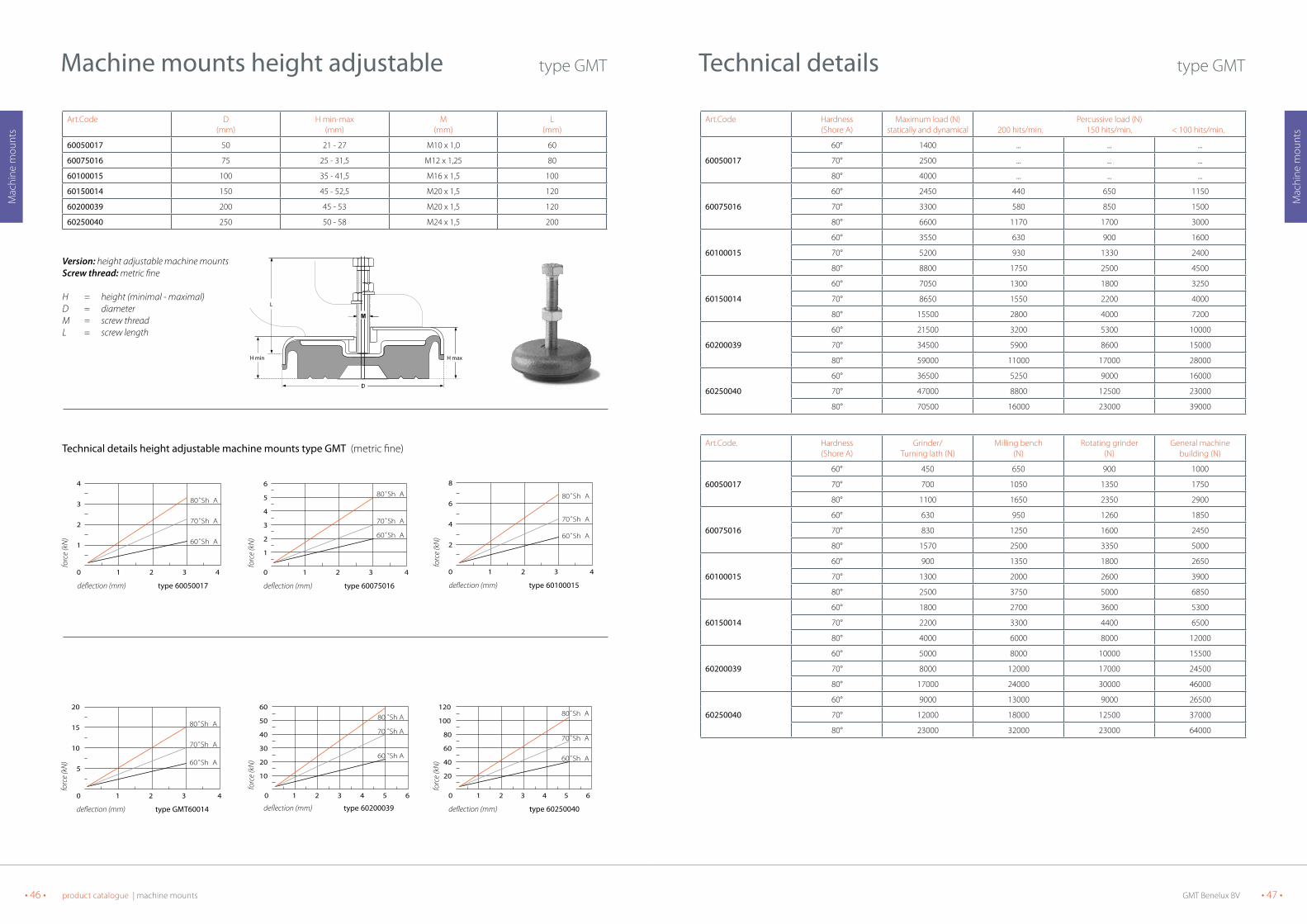
technical details type GMT
Art.Code D(mm)
H min-max(mm)
M(mm)
L(mm)
60050017 50 21 - 27 M10 x 1,0 60
60075016 75 25 - 31,5 M12 x 1,25 80
60100015 100 35 - 41,5 M16 x 1,5 100
60150014 150 45 - 52,5 M20 x 1,5 120
60200039 200 45 - 53 M20 x 1,5 120
60250040 250 50 - 58 M24 x 1,5 200
Machine mounts height adjustable type GMT
H min
D
L
H max
D
L
1 2 3 40
1
2
3
4
5
6
60˚Sh A
70˚Sh A
80˚Sh A
deflection (mm)
forc
e (k
N)
type 60075016
1 2 3 40
1
2
3
4
60˚Sh A
70˚Sh A
80˚Sh A
deflection (mm)
forc
e (k
N)
type 60050017
1 2 3 40
2
4
6
8
60˚Sh A
70˚Sh A
80˚Sh A
deflection (mm)
forc
e (k
N)
type 60100015
1 2 3 4 5 60
10
20
30
40
50
60
60 ˚Sh A
70 ˚Sh A
80 ˚Sh A
deflection (mm)
forc
e (k
N)
type 60200039
1 2 3 4 5 60
20
40
60
80
100
120
60˚Sh A
80˚Sh A
70˚Sh A
deflection (mm)
forc
e (k
N)
type 60250040
1 2 3 40
5
10
15
20
60˚Sh A
70˚Sh A
80˚Sh A
deflection (mm)
forc
e (k
N)
type GMT60014
Version: height adjustable machine mountsScrew thread: metric fine
H = height (minimal - maximal)D = diameterM = screw threadL = screw length
technical details height adjustable machine mounts type GMt (metric fine)
GMT Benelux BV • 49 •• 48 • product catalogue | machine mounts
Mac
hine
mou
nts
Mac
hine
mou
nts
Art.Code Hardness(Shore A)
Maximum load (N)statically and dynamical
Percussive load (N) 200 hits/min. 150 hits/min. < 100 hits/min.
nM80
60° 3500 450 600 1100
70° 4000 600 800 1500
80° 4500 1150 1700 3000
nM100
60° 5000 600 900 1400
70° 8000 1100 1600 3000
80° 9000 1500 2200 3500
nM120
60° 9000 1100 1600 2500
70° 10000 1400 2000 3700
80° 11000 1800 2600 4200
nM160
60° 30000 1400 1800 3000
70° 40000 1800 2700 4500
80° 50000 2000 4000 8000
nM185
60° 50000 2500 6500 15000
70° 55000 4500 10000 22000
80° 60000 10000 18000 26000
Art.Code. Hardness(Shore A)
Grinder/Turning lath (N)
Milling bench(N)
Rotating grinder(N)
General machinebuilding (N)
nM80
60° 600 900 1300 1500
70° 800 1200 2000 2000
80° 1600 2500 3000 3000
nM100
60° 900 1200 1700 2200
70° 1600 2400 3100 4000
80° 2200 3000 4000 5000
nM120
60° 1600 2100 3000 4000
70° 2000 3000 3900 5000
80° 2700 3700 5000 6000
nM160
60° 2000 2500 4000 7000
70° 2500 3500 6000 10000
80° 3800 5000 9000 15000
nM185
60° 5500 10000 17000 20000
70° 9000 18000 32000 35000
80° 16000 20000 40000 40000
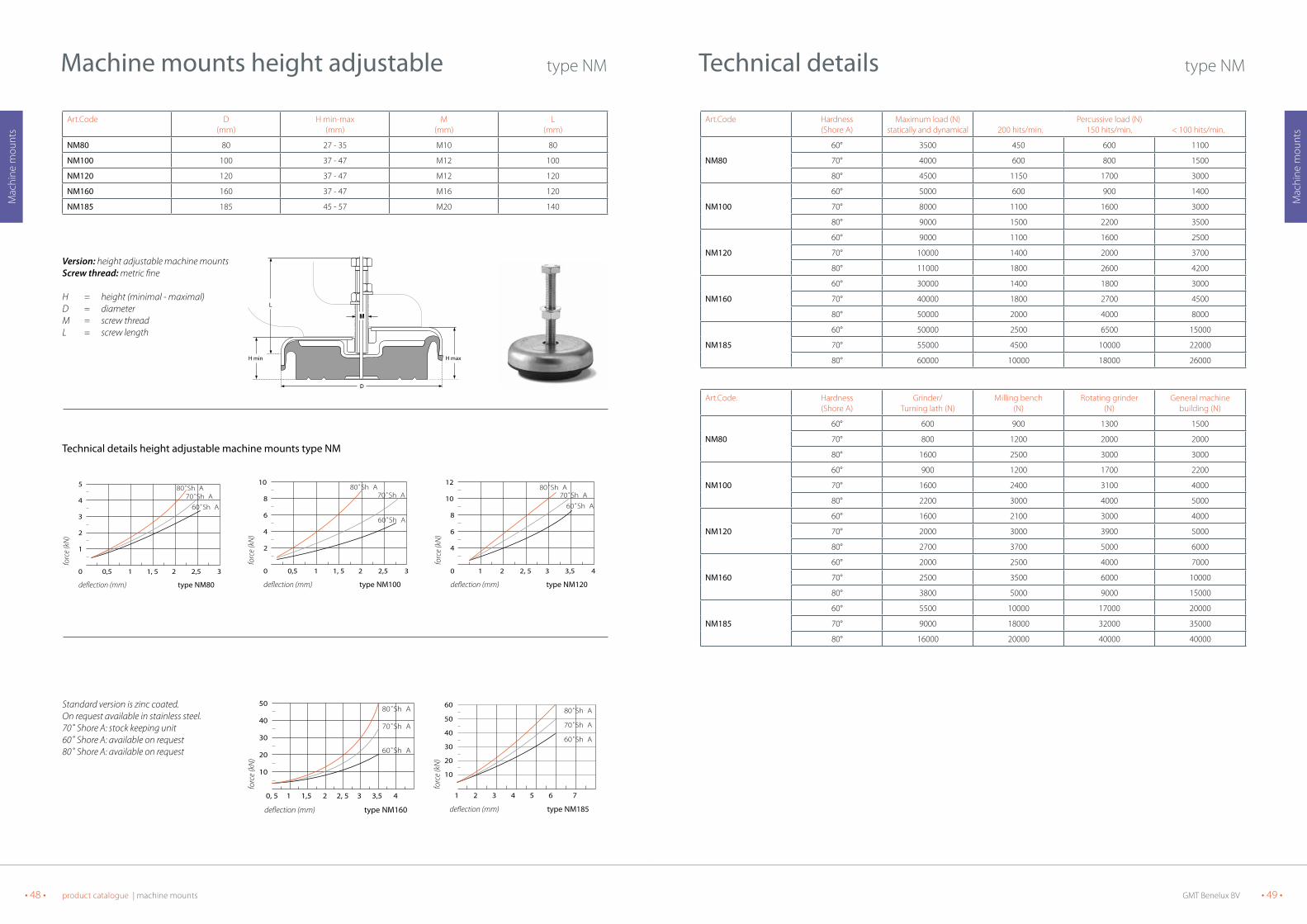
technical details type NM
Art.Code D(mm)
H min-max(mm)
M(mm)
L(mm)
nM80 80 27 - 35 M10 80
nM100 100 37 - 47 M12 100
nM120 120 37 - 47 M12 120
nM160 160 37 - 47 M16 120
nM185 185 45 - 57 M20 140
Machine mounts height adjustable type NM
H min
D
L
H max
D
L
DIN 933
0,5 1 1, 5 2 2,5 30
2
4
6
8
10
60˚Sh A
70˚Sh A80˚Sh A
deflection (mm)
forc
e (k
N)
type NM100
0,5 1 1, 5 2 2,5 30
1
2
3
4
5
60˚Sh A
70˚Sh A80˚Sh A
deflection (mm)
forc
e (k
N)
type NM80
1 2 2, 5 3 3,5 40
4
6
8
10
12
60˚Sh A
70˚Sh A80˚Sh A
deflection (mm)
forc
e (k
N)
type NM120
0, 5 1 1,5 2 2, 5 3 3,5 4
10
20
30
40
50
60˚Sh A
70˚Sh A
80˚Sh A
deflection (mm)
forc
e (k
N)
type NM160
10
20
30
40
50
60
1 2 3 4 5 6 7
60˚Sh A
70˚Sh A
80˚Sh A
deflection (mm)
forc
e (k
N)
type NM185
Version: height adjustable machine mountsScrew thread: metric fine
H = height (minimal - maximal)D = diameterM = screw threadL = screw length
Standard version is zinc coated.On request available in stainless steel.70˚ Shore A: stock keeping unit60˚ Shore A: available on request80˚ Shore A: available on request
technical details height adjustable machine mounts type nM
GMT Benelux BV • 51 •
Rail
elem
ents
• 50 • product catalogue | machine mounts
Mac
hine
mou
nts
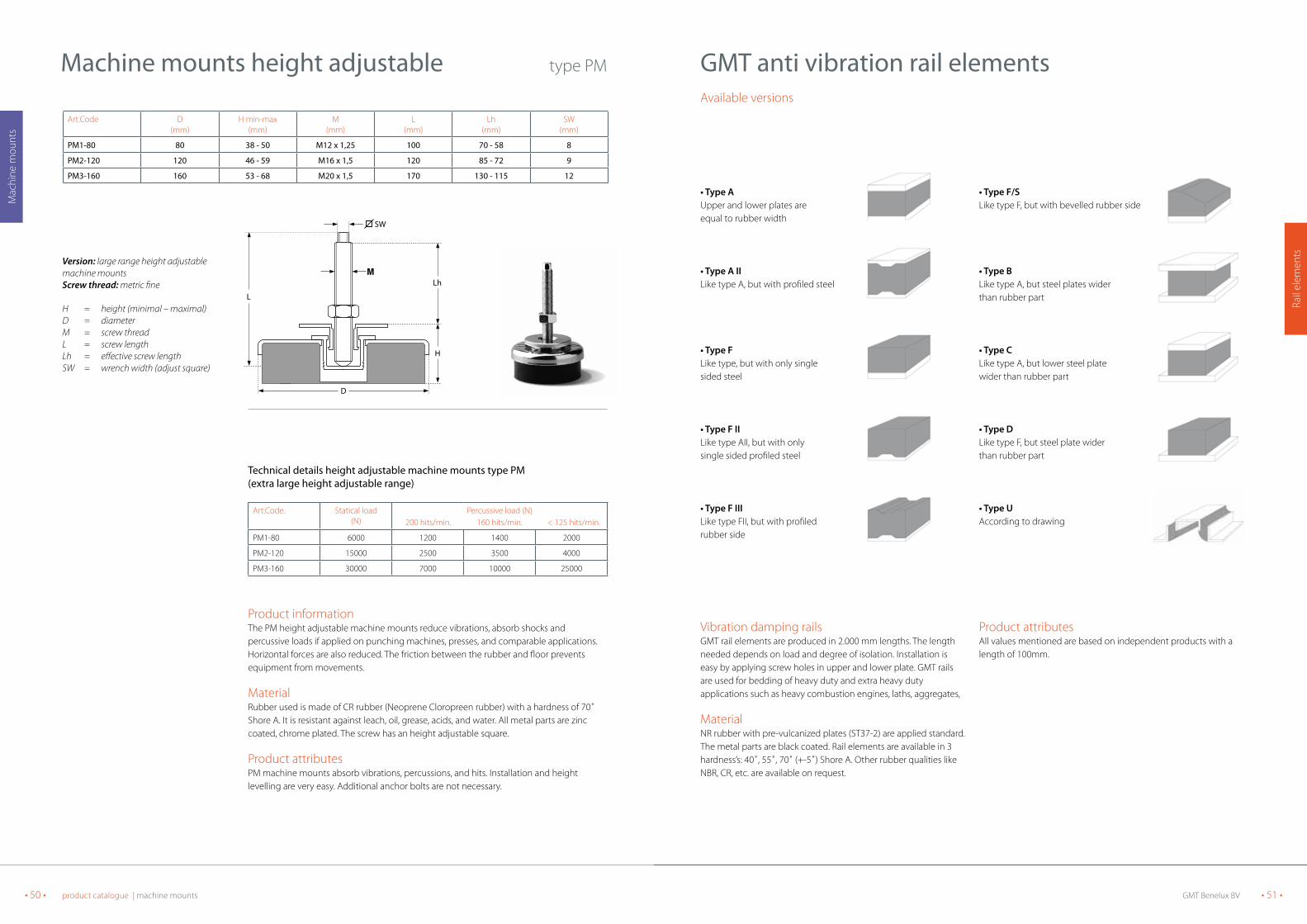
• Type AUpper and lower plates areequal to rubber width
• Type A IILike type A, but with profiled steel
• Type FLike type, but with only singlesided steel
• Type F IILike type AII, but with onlysingle sided profiled steel
• Type F IIILike type FII, but with profiledrubber side
• Type F/SLike type F, but with bevelled rubber side
• Type BLike type A, but steel plates widerthan rubber part
• Type CLike type A, but lower steel platewider than rubber part
• Type DLike type F, but steel plate widerthan rubber part
• Type U According to drawing
GMt anti vibration rail elements
Vibration damping railsGMT rail elements are produced in 2.000 mm lengths. The length needed depends on load and degree of isolation. Installation is easy by applying screw holes in upper and lower plate. GMT railsare used for bedding of heavy duty and extra heavy duty applications such as heavy combustion engines, laths, aggregates,
MaterialNR rubber with pre-vulcanized plates (ST37-2) are applied standard. The metal parts are black coated. Rail elements are available in 3 hardness’s: 40˚, 55˚, 70˚ (+-5˚) Shore A. Other rubber qualities like NBR, CR, etc. are available on request.
Product attributesAll values mentioned are based on independent products with a length of 100mm.
Available versions
Art.Code D(mm)
H min-max(mm)
M(mm)
L(mm)
Lh(mm)
SW(mm)
PM1-80 80 38 - 50 M12 x 1,25 100 70 - 58 8
PM2-120 120 46 - 59 M16 x 1,5 120 85 - 72 9
PM3-160 160 53 - 68 M20 x 1,5 170 130 - 115 12
Machine mounts height adjustable type PM
Version: large range height adjustable machine mountsScrew thread: metric fine
H = height (minimal – maximal)D = diameterM = screw threadL = screw lengthLh = effective screw lengthSW = wrench width (adjust square)
technical details height adjustable machine mounts type PM(extra large height adjustable range)
Art.Code. Statical load(N)
Percussive load (N) 200 hits/min. 160 hits/min. < 125 hits/min.
PM1-80 6000 1200 1400 2000
PM2-120 15000 2500 3500 4000
PM3-160 30000 7000 10000 25000
Product informationThe PM height adjustable machine mounts reduce vibrations, absorb shocks and percussive loads if applied on punching machines, presses, and comparable applications. Horizontal forces are also reduced. The friction between the rubber and floor prevents equipment from movements.
MaterialRubber used is made of CR rubber (Neoprene Cloropreen rubber) with a hardness of 70˚ Shore A. It is resistant against leach, oil, grease, acids, and water. All metal parts are zinc coated, chrome plated. The screw has an height adjustable square.
Product attributesPM machine mounts absorb vibrations, percussions, and hits. Installation and height levelling are very easy. Additional anchor bolts are not necessary.
D
Lh
SW
H
L
GMT Benelux BV • 53 •• 52 • product catalogue | rail elements
Rail
elem
ents
Rail
elem
ents
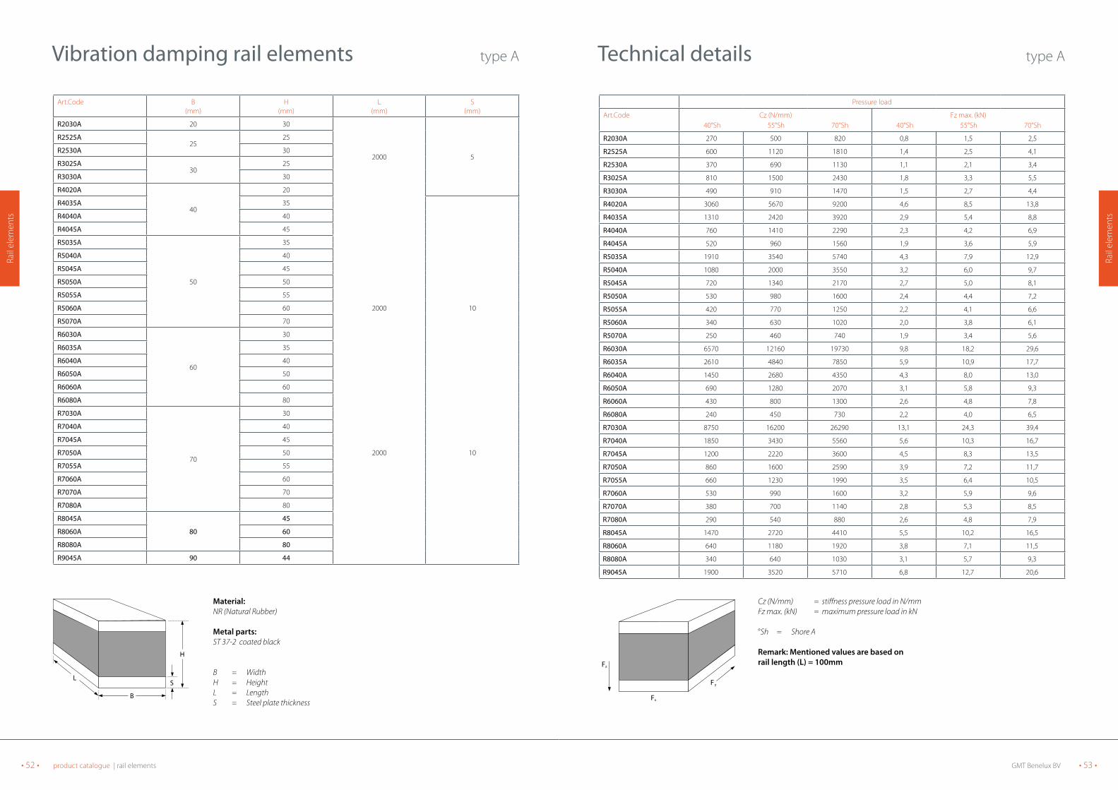
Pressure load
Art.Code Cz (N/mm) 40°Sh 55°Sh 70°Sh
Fz max. (kN) 40°Sh 55°Sh 70°Sh
R2030A 270 500 820 0,8 1,5 2,5
R2525A 600 1120 1810 1,4 2,5 4,1
R2530A 370 690 1130 1,1 2,1 3,4
R3025A 810 1500 2430 1,8 3,3 5,5
R3030A 490 910 1470 1,5 2,7 4,4
R4020A 3060 5670 9200 4,6 8,5 13,8
R4035A 1310 2420 3920 2,9 5,4 8,8
R4040A 760 1410 2290 2,3 4,2 6,9
R4045A 520 960 1560 1,9 3,6 5,9
R5035A 1910 3540 5740 4,3 7,9 12,9
R5040A 1080 2000 3550 3,2 6,0 9,7
R5045A 720 1340 2170 2,7 5,0 8,1
R5050A 530 980 1600 2,4 4,4 7,2
R5055A 420 770 1250 2,2 4,1 6,6
R5060A 340 630 1020 2,0 3,8 6,1
R5070A 250 460 740 1,9 3,4 5,6
R6030A 6570 12160 19730 9,8 18,2 29,6
R6035A 2610 4840 7850 5,9 10,9 17,7
R6040A 1450 2680 4350 4,3 8,0 13,0
R6050A 690 1280 2070 3,1 5,8 9,3
R6060A 430 800 1300 2,6 4,8 7,8
R6080A 240 450 730 2,2 4,0 6,5
R7030A 8750 16200 26290 13,1 24,3 39,4
R7040A 1850 3430 5560 5,6 10,3 16,7
R7045A 1200 2220 3600 4,5 8,3 13,5
R7050A 860 1600 2590 3,9 7,2 11,7
R7055A 660 1230 1990 3,5 6,4 10,5
R7060A 530 990 1600 3,2 5,9 9,6
R7070A 380 700 1140 2,8 5,3 8,5
R7080A 290 540 880 2,6 4,8 7,9
R8045A 1470 2720 4410 5,5 10,2 16,5
R8060A 640 1180 1920 3,8 7,1 11,5
R8080A 340 640 1030 3,1 5,7 9,3
R9045A 1900 3520 5710 6,8 12,7 20,6
technical details type A
Fz
Fx
Fy
Cz (N/mm) = stiffness pressure load in N/mmFz max. (kN) = maximum pressure load in kN
°Sh = Shore A
Remark: Mentioned values are based onrail length (L) = 100mm
Vibration damping rail elements type A
Art.Code B(mm)
H(mm)
L(mm)
S(mm)
R2030A 20 30
2000 5
R2525A 25
25
R2530A 30
R3025A 30
25
R3030A 30
R4020A
40
20
R4035A 35
R4040A 40
R4045A 45
R5035A
50
35
R5040A 40
R5045A 45
R5050A 50
R5055A 55
R5060A 60 2000 10
R5070A 70
R6030A
60
30
R6035A 35
R6040A 40
R6050A 50
R6060A 60
R6080A 80
R7030A
70
30
R7040A 40
R7045A 45
R7050A 50 2000 10
R7055A 55
R7060A 60
R7070A 70
R7080A 80
R8045A
80
45
R8060A 60
R8080A 80
R9045A 90 44
L
B
H
S
Material:NR (Natural Rubber)
Metal parts: ST 37-2 coated black
B = WidthH = HeightL = LengthS = Steel plate thickness
GMT Benelux BV • 55 •• 54 • product catalogue | rail elements
Rail
elem
ents
Rail
elem
ents
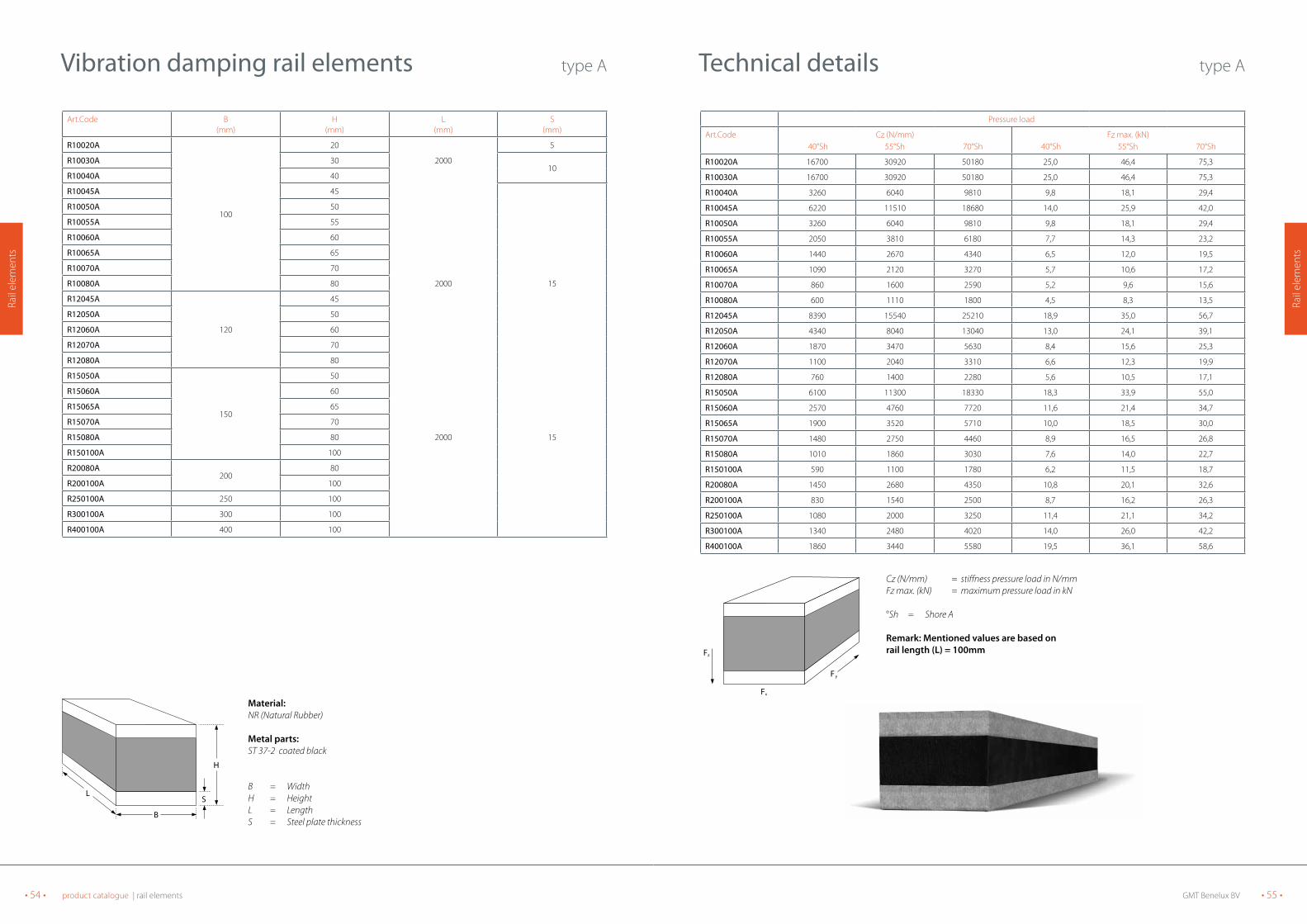
Pressure load
Art.Code Cz (N/mm) 40°Sh 55°Sh 70°Sh
Fz max. (kN) 40°Sh 55°Sh 70°Sh
R10020A 16700 30920 50180 25,0 46,4 75,3
R10030A 16700 30920 50180 25,0 46,4 75,3
R10040A 3260 6040 9810 9,8 18,1 29,4
R10045A 6220 11510 18680 14,0 25,9 42,0
R10050A 3260 6040 9810 9,8 18,1 29,4
R10055A 2050 3810 6180 7,7 14,3 23,2
R10060A 1440 2670 4340 6,5 12,0 19,5
R10065A 1090 2120 3270 5,7 10,6 17,2
R10070A 860 1600 2590 5,2 9,6 15,6
R10080A 600 1110 1800 4,5 8,3 13,5
R12045A 8390 15540 25210 18,9 35,0 56,7
R12050A 4340 8040 13040 13,0 24,1 39,1
R12060A 1870 3470 5630 8,4 15,6 25,3
R12070A 1100 2040 3310 6,6 12,3 19,9
R12080A 760 1400 2280 5,6 10,5 17,1
R15050A 6100 11300 18330 18,3 33,9 55,0
R15060A 2570 4760 7720 11,6 21,4 34,7
R15065A 1900 3520 5710 10,0 18,5 30,0
R15070A 1480 2750 4460 8,9 16,5 26,8
R15080A 1010 1860 3030 7,6 14,0 22,7
R150100A 590 1100 1780 6,2 11,5 18,7
R20080A 1450 2680 4350 10,8 20,1 32,6
R200100A 830 1540 2500 8,7 16,2 26,3
R250100A 1080 2000 3250 11,4 21,1 34,2
R300100A 1340 2480 4020 14,0 26,0 42,2
R400100A 1860 3440 5580 19,5 36,1 58,6
technical details type A
Fz
Fx
Fy
Cz (N/mm) = stiffness pressure load in N/mmFz max. (kN) = maximum pressure load in kN
°Sh = Shore A
Remark: Mentioned values are based onrail length (L) = 100mm
Art.Code B(mm)
H(mm)
L(mm)
S(mm)
R10020A
100
20 5
R10030A 30 200010
R10040A 40
R10045A 45
R10050A 50
R10055A 55
R10060A 60
R10065A 65
R10070A 70
R10080A 80 2000 15
R12045A
120
45
R12050A 50
R12060A 60
R12070A 70
R12080A 80
R15050A
150
50
R15060A 60
R15065A 65
R15070A 70
R15080A 80 2000 15
R150100A 100
R20080A200
80
R200100A 100
R250100A 250 100
R300100A 300 100
R400100A 400 100
Vibration damping rail elements type A
L
B
H
S
Material:NR (Natural Rubber)
Metal parts: ST 37-2 coated black
B = WidthH = HeightL = LengthS = Steel plate thickness
GMT Benelux BV • 57 •• 56 • product catalogue | rail elements
Rail
elem
ents
Rail
elem
ents
Pressure load
Art.Code Cz (N/mm) 40°Sh 55°Sh 70°Sh
Fz max. (kN) 40°Sh 55°Sh 70°Sh
R5035A2 840 1550 2520 2,9 5,3 8,7
R5040A2 600 1100 1790 2,5 4,6 7,5
R5045A2 460 850 1370 2,3 4,2 6,8
R5050A2 370 680 1100 2,1 3,9 6,2
R5055A2 310 570 920 2,0 3,7 5,9
R5060A2 260 480 790 1,9 3,5 5,7
R5070A2 200 370 610 1,8 3,3 5,3
R6035A2 1200 2230 3620 4,0 7,4 11,9
R6060A2 340 630 1020 2,4 4,4 7,2
R7030A2 2950 5470 8880 7,1 13,1 21,3
R7045A2 810 1510 2450 3,7 7,0 11,4
R7055A2 510 950 1540 3,2 5,8 9,5
R7060A2 430 790 1290 3,0 5,5 8,9
R7070A2 320 600 970 2,7 5,0 8,1
R7080A2 260 470 770 2,5 4,7 7,6
R10040A2 2670 4940 8020 8,8 16,3 26,5
R10045A2 1760 3270 5300 7,1 13,2 21,5
R10050A2 1280 2370 3850 6,1 11,4 18,5
R10055A2 990 1830 2970 5,5 10,1 16,5
R10060A2 790 1470 2390 5,0 9,3 15,1
R10070A2 560 1040 1690 4,4 8,1 13,2
R10080A2 430 800 1300 4,0 7,4 12,1
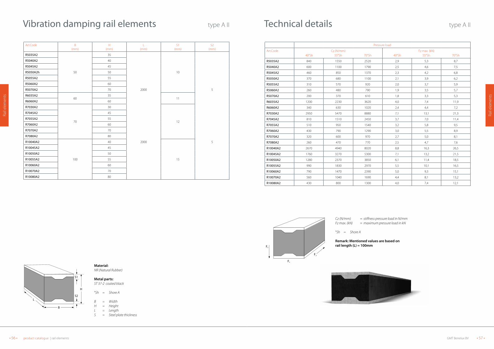
technical details type A II
Fx
Fy
Fz
Cz (N/mm) = stiffness pressure load in N/mmFz max. (kN) = maximum pressure load in kN
°Sh = Shore A
Remark: Mentioned values are based onrail length (L) = 100mm
Art.Code B(mm)
H(mm)
L(mm)
S1(mm)
S2(mm)
R5035A2
50
35
10
R5040A2 40
R5045A2 45
R5050A2h 50
R5055A2 55
R5060A2 60
R5070A2 70 2000 5
R6035A260
3511
R6060A2 60
R7030A2
70
30
12
R7045A2 45
R7055A2 55
R7060A2 60
R7070A2 70
R7080A2 80
R10040A2
100
40 2000
15
5
R10045A2 45
R10050A2 50
R10055A2 55
R10060A2 60
R10070A2 70
R10080A2 80
Vibration damping rail elements type A II
L
B
H
S2
S1
Material:NR (Natural Rubber)
Metal parts: ST 37-2 coated black
°Sh = Shore A
B = WidthH = HeightL = LengthS = Steel plate thickness

GMT Benelux BV • 59 •• 58 • product catalogue | rail elements
Rail
elem
ents
Rail
elem
ents
Pressure load
Art.Code Cz (N/mm) 40°Sh 55°Sh 70°Sh
Fz max. (kN) 40°Sh 55°Sh 70°Sh
R2030F 200 370 590 0,7 1,4 2,2
R2525F 370 690 1130 1,1 2,1 3,4
R2530F 270 490 800 1,0 1,9 3,0
R3025F 810 1500 2430 1,8 3,4 5,5
R3030F 490 910 1470 1,5 2,7 4,4
R4020F 1310 2420 3920 2,9 5,4 8,8
R4035F 520 960 1560 2,0 3,6 5,9
R4040F 390 720 1170 1,8 3,2 5,3
R4045F 310 570 930 1,6 3,0 4,8
R5035F 720 1340 2170 2,7 5,0 8,1
R5040F 530 980 1600 2,4 4,4 7,2
R5045F 420 770 1250 2,2 4,0 6,6
R5050F 340 630 1020 2,0 3,8 6,1
R5055F 270 530 860 1,9 3,6 5,8
R5060F 250 460 740 1,9 3,4 5,6
R5070F 190 360 580 1,7 3,2 5,2
R6030F 1450 2680 4350 4,3 8,0 13,0
R6035F 950 1760 2860 3,6 6,6 10,7
R6040F 690 1280 2070 3,1 5,8 9,3
R6050F 430 800 1300 2,6 4,9 7,8
R6060F 310 580 940 2,3 4,3 7,0
R6080F 200 360 590 2,0 3,8 6,2
R7030F 1850 3430 5560 5,6 10,3 16,7
R7040F 860 1600 2590 3,9 7,2 11,7
R7045F 660 1230 1990 3,4 6,4 10,5
R7050F 530 990 1600 3,2 5,9 9,6
R7055F 440 820 1330 3,0 5,6 9,0
R7060F 380 700 1140 2,8 5,3 8,5
R7070F 290 540 880 2,6 4,9 7,9
R7080F 240 440 710 2,5 4,6 10,5
R8045F 800 1480 2400 4,2 7,8 12,6
R8060F 450 830 1350 3,4 6,2 10,1
R8080F 280 510 830 2,9 5,4 8,8
R9045F 940 1740 2820 4,9 9,1 14,8
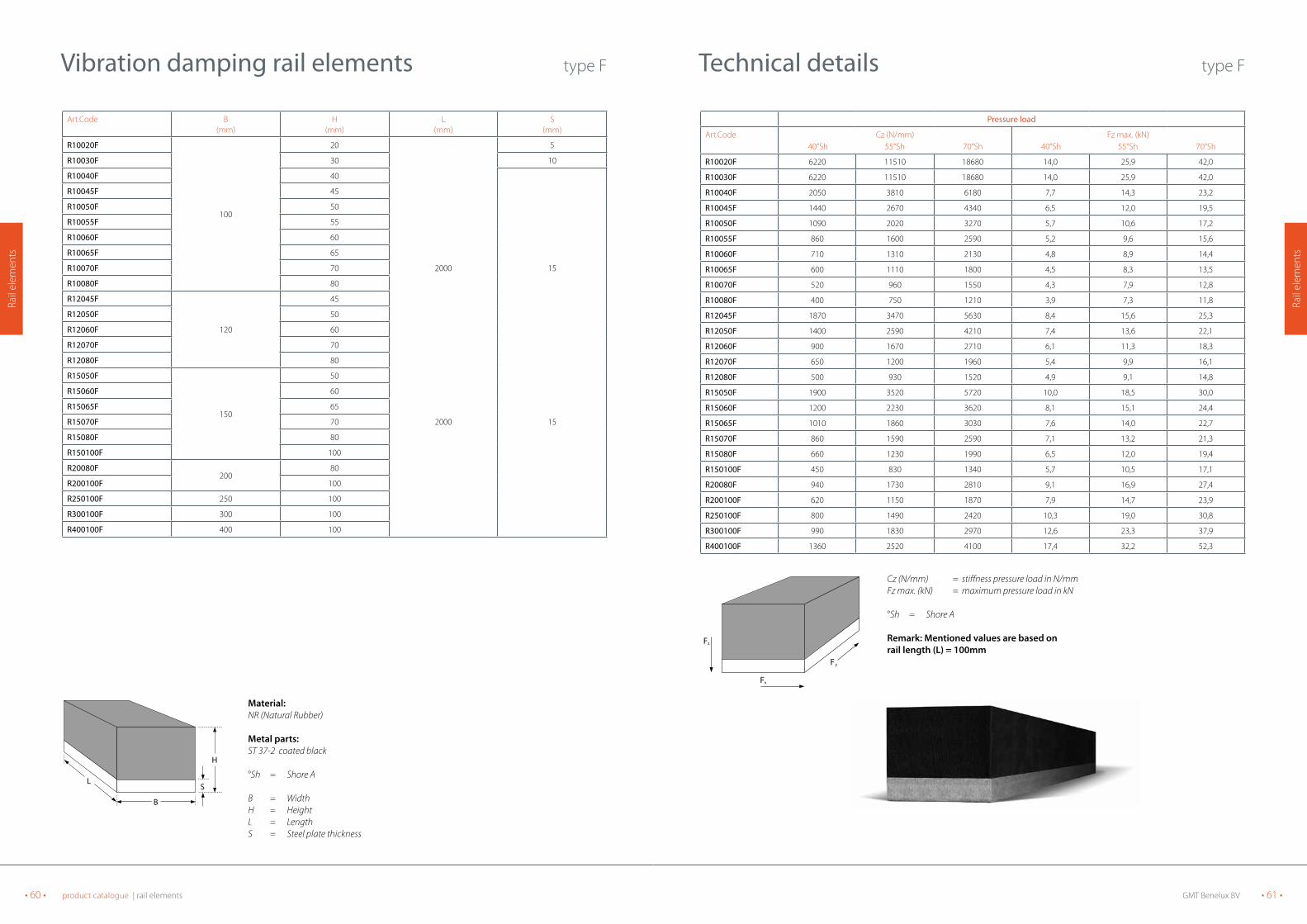
technical details type F
Fx
Fy
Fz
Cz (N/mm) = stiffness pressure load in N/mmFz max. (kN) = maximum pressure load in kN
°Sh = Shore A
Remark: Mentioned values are based onrail length (L) = 100mm
Art.Code B(mm)
H(mm)
L(mm)
S(mm)
R2030F 20 30
5R2525F25
25
R2530F 30
R3025F30
25 200010
R3030F 30
R4020F
40
20 5
R4035F 35
R4040F 40
R4045F 45
R5035F
50
35
R5040F 40
R5045F 45
R5050F 50
R5055F 55
R5060F 60 2000 10
R5070F 70
R6030F
60
30
R6035F 35
R6040F 40
R6050F 50
R6060F 60
R6080F 80
R7030F
70
30
R7040F 40
R7045F 45
R7050F 50 2000 10
R7055F 55
R7060F 60
R7070F 70
R7080F 80
R8045F
80
45
R8060F 60
R8080F 80
R9045F 90 45
Vibration damping rail elements type F
L
B
H
S
Material:NR (Natural Rubber)
Metal parts: ST 37-2 coated black
°Sh = Shore A
B = WidthH = HeightL = LengthS = Steel plate thickness
GMT Benelux BV • 61 •• 60 • product catalogue | rail elements
Rail
elem
ents
Rail
elem
ents
Pressure load
Art.Code Cz (N/mm) 40°Sh 55°Sh 70°Sh
Fz max. (kN) 40°Sh 55°Sh 70°Sh
R10020F 6220 11510 18680 14,0 25,9 42,0
R10030F 6220 11510 18680 14,0 25,9 42,0
R10040F 2050 3810 6180 7,7 14,3 23,2
R10045F 1440 2670 4340 6,5 12,0 19,5
R10050F 1090 2020 3270 5,7 10,6 17,2
R10055F 860 1600 2590 5,2 9,6 15,6
R10060F 710 1310 2130 4,8 8,9 14,4
R10065F 600 1110 1800 4,5 8,3 13,5
R10070F 520 960 1550 4,3 7,9 12,8
R10080F 400 750 1210 3,9 7,3 11,8
R12045F 1870 3470 5630 8,4 15,6 25,3
R12050F 1400 2590 4210 7,4 13,6 22,1
R12060F 900 1670 2710 6,1 11,3 18,3
R12070F 650 1200 1960 5,4 9,9 16,1
R12080F 500 930 1520 4,9 9,1 14,8
R15050F 1900 3520 5720 10,0 18,5 30,0
R15060F 1200 2230 3620 8,1 15,1 24,4
R15065F 1010 1860 3030 7,6 14,0 22,7
R15070F 860 1590 2590 7,1 13,2 21,3
R15080F 660 1230 1990 6,5 12,0 19,4
R150100F 450 830 1340 5,7 10,5 17,1
R20080F 940 1730 2810 9,1 16,9 27,4
R200100F 620 1150 1870 7,9 14,7 23,9
R250100F 800 1490 2420 10,3 19,0 30,8
R300100F 990 1830 2970 12,6 23,3 37,9
R400100F 1360 2520 4100 17,4 32,2 52,3
technical details type F
Fx
Fy
Fz
Cz (N/mm) = stiffness pressure load in N/mmFz max. (kN) = maximum pressure load in kN
°Sh = Shore A
Remark: Mentioned values are based onrail length (L) = 100mm
Art.Code B(mm)
H(mm)
L(mm)
S(mm)
R10020F
100
20 5
R10030F 30 10
R10040F 40
R10045F 45
R10050F 50
R10055F 55
R10060F 60
R10065F 65
R10070F 70 2000 15
R10080F 80
R12045F
120
45
R12050F 50
R12060F 60
R12070F 70
R12080F 80
R15050F
150
50
R15060F 60
R15065F 65
R15070F 70 2000 15
R15080F 80
R150100F 100
R20080F200
80
R200100F 100
R250100F 250 100
R300100F 300 100
R400100F 400 100
Vibration damping rail elements type F
L
B
H
S
Material:NR (Natural Rubber)
Metal parts: ST 37-2 coated black
°Sh = Shore A
B = WidthH = HeightL = LengthS = Steel plate thickness
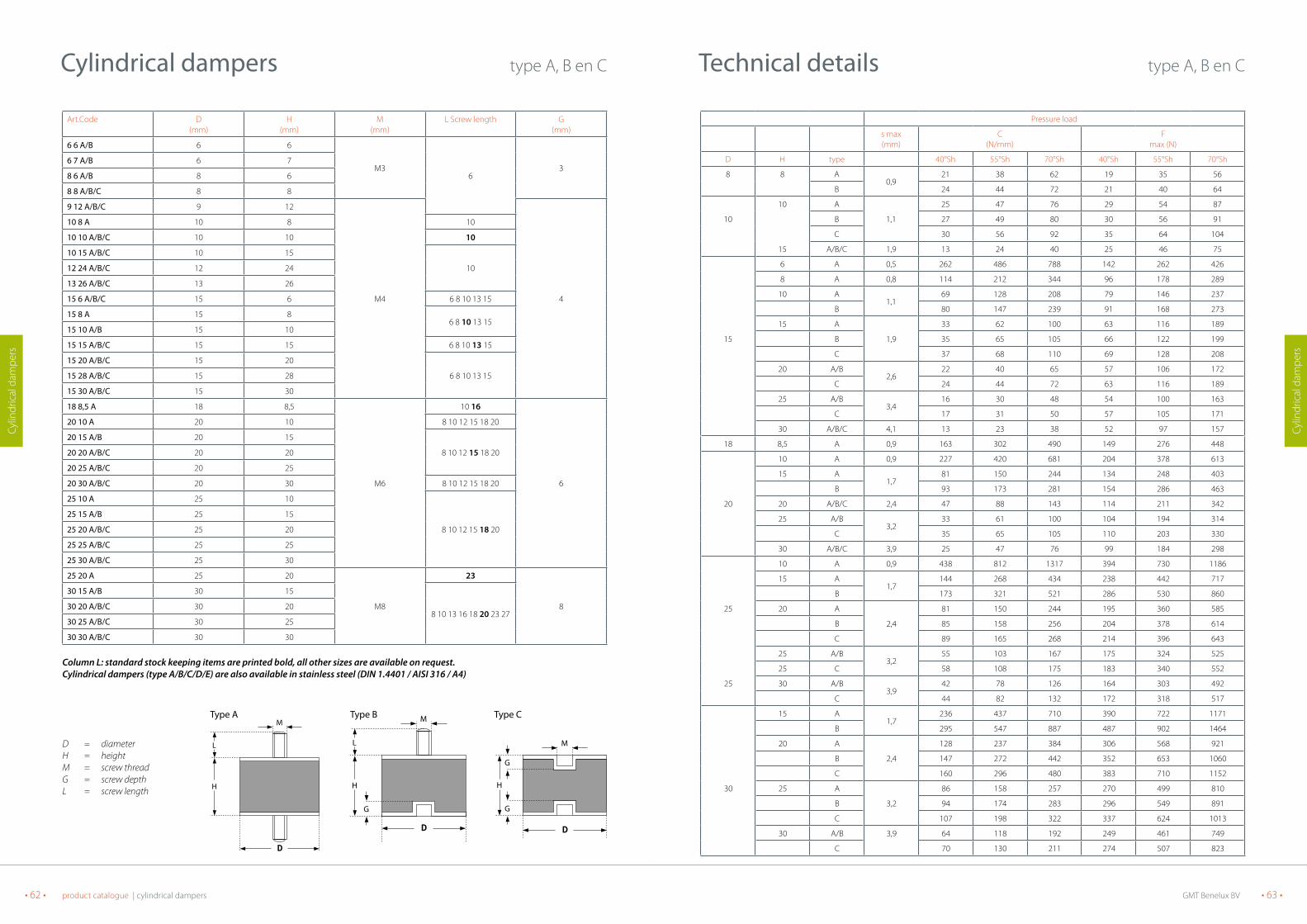
GMT Benelux BV • 63 •• 62 • product catalogue | cylindrical dampers
Cylin
dric
al d
ampe
rs
Cylin
dric
al d
ampe
rs
technical details type A, B en C
Pressure load
s max (mm)
C (N/mm)
F max (N)
D H type 40°Sh 55°Sh 70°Sh 40°Sh 55°Sh 70°Sh
8 8 A0,9
21 38 62 19 35 56
B 24 44 72 21 40 64
10
15
A
1,1
25 47 76 29 54 87
10 B 27 49 80 30 56 91
C 30 56 92 35 64 104
A/B/C 1,9 13 24 40 25 46 75
6 A 0,5 262 486 788 142 262 426
8 A 0,8 114 212 344 96 178 289
10 A1,1
69 128 208 79 146 237
B 80 147 239 91 168 273
15 A
1,9
33 62 100 63 116 189
15 B 35 65 105 66 122 199
C 37 68 110 69 128 208
20 A/B2,6
22 40 65 57 106 172
C 24 44 72 63 116 189
25 A/B3,4
16 30 48 54 100 163
C 17 31 50 57 105 171
30 A/B/C 4,1 13 23 38 52 97 157
18 8,5 A 0,9 163 302 490 149 276 448
10 A 0,9 227 420 681 204 378 613
15 A1,7
81 150 244 134 248 403
B 93 173 281 154 286 463
20 20 A/B/C 2,4 47 88 143 114 211 342
25 A/B3,2
33 61 100 104 194 314
C 35 65 105 110 203 330
30 A/B/C 3,9 25 47 76 99 184 298
10 A 0,9 438 812 1317 394 730 1186
15 A1,7
144 268 434 238 442 717
B 173 321 521 286 530 860
25 20 A
2,4
81 150 244 195 360 585
B 85 158 256 204 378 614
C 89 165 268 214 396 643
25 A/B3,2
55 103 167 175 324 525
25 C 58 108 175 183 340 552
25 30 A/B3,9
42 78 126 164 303 492
C 44 82 132 172 318 517
15 A1,7
236 437 710 390 722 1171
B 295 547 887 487 902 1464
20 A
2,4
128 237 384 306 568 921
B 147 272 442 352 653 1060
C 160 296 480 383 710 1152
30 25 A
3,2
86 158 257 270 499 810
B 94 174 283 296 549 891
C 107 198 322 337 624 1013
30 A/B 3,9 64 118 192 249 461 749
C 70 130 211 274 507 823
Cylindrical dampers type A, B en C
Art.Code D(mm)
H(mm)
M(mm)
L Screw length G(mm)
6 6 A/B 6 6
M36
36 7 A/B 6 7
8 6 A/B 8 6
8 8 A/B/C 8 8
9 12 A/B/C 9 12
M4 4
10 8 A 10 8 10
10 10 A/B/C 10 10 10
10 15 A/B/C 10 15
1012 24 A/B/C 12 24
13 26 A/B/C 13 26
15 6 A/B/C 15 6 6 8 10 13 15
15 8 A 15 86 8 10 13 15
15 10 A/B 15 10
15 15 A/B/C 15 15 6 8 10 13 15
15 20 A/B/C 15 20
6 8 10 13 1515 28 A/B/C 15 28
15 30 A/B/C 15 30
18 8,5 A 18 8,5
M6
10 16
6
20 10 A 20 10 8 10 12 15 18 20
20 15 A/B 20 15
8 10 12 15 18 2020 20 A/B/C 20 20
20 25 A/B/C 20 25
20 30 A/B/C 20 30 8 10 12 15 18 20
25 10 A 25 10
8 10 12 15 18 20
25 15 A/B 25 15
25 20 A/B/C 25 20
25 25 A/B/C 25 25
25 30 A/B/C 25 30
25 20 A 25 20
M8
23
8
30 15 A/B 30 15
8 10 13 16 18 20 23 2730 20 A/B/C 30 20
30 25 A/B/C 30 25
30 30 A/B/C 30 30
Column L: standard stock keeping items are printed bold, all other sizes are available on request.Cylindrical dampers (type A/B/C/D/E) are also available in stainless steel (DIN 1.4401 / AISI 316 / A4)
D = diameterH = heightM = screw threadG = screw depthL = screw length
L
H
M
L
H
M
G
H
M
G
G
type A type B type C

GMT Benelux BV • 65 •• 64 • product catalogue | cylindrical dampers
Cylin
dric
al d
ampe
rs
Cylin
dric
al d
ampe
rs
technical details type A, B en C
Pressure load
s max (mm)
C (N/mm)
F max (N)
D H type 40°Sh 55°Sh 70°Sh 40°Sh 55°Sh 70°Sh
30 40 A/B/C 5,4 42 78 127 227 421 683
50 A/B/C 6,9 31 58 94 216 400 649
20 A2,4
271 502 815 650 1204 1955
B 312 577 937 748 1385 2248
30 A
3,9
127 235 381 495 916 1487
B 133 247 400 519 962 1561
40 C 139 258 419 544 1008 1635
40 A
5,4
81 150 243 437 810 1314
B 89 165 268 481 891 1446
C 85 157 256 459 850 1380
66 A/B/C 9,3 41 76 124 383 710 1152
20 A2,1
646 1196 1942 1356 2512 4078
B 807 1495 2427 1695 3140 5097
25 A2,9
370 685 1112 1054 1952 3169
B 444 822 1334 1265 2343 3803
30 A
3,6
251 465 755 904 1674 2716
B 289 535 868 1039 1925 3124
50 C 301 558 905 1084 2008 3260
40 A/B5,1
149 275 447 758 1403 2278
C 156 289 469 796 1474 2392
45 A/B5,9
123 227 369 718 1329 2157
C 129 239 387 753 1396 2265
50 A/B/C 6,6 104 193 313 688 1275 2069
55 A/B/C 7,4 91 168 272 666 1233 2001
35 A
4,4
298 552 896 1296 2400 3896
B 343 635 1030 1490 2760 4480
C 257 662 1075 1555 2880 4675
60 40 A
5,1
233 431 700 1188 2200 3570
B 256 474 770 1306 2420 3928
C 268 496 805 1366 2530 4106
45 A/B5,9
190 352 572 1113 2061 3345
C 200 370 600 1168 2164 3512
35 A
4,4
447 828 1344 1944 3602 5846
B 469 869 1411 2042 3782 6138
70 C 492 911 1478 2139 3962 6431
45 A/B5,9
279 516 838 1631 3020 4902
C 293 542 880 1712 3171 5147
25 A2,9
1178 2183 3543 3358 6221 10097
B 1414 2619 4251 4030 7465 12117
40 A
5,1
413 765 1241 2105 3899 6329
75 B 433 803 1303 2210 4094 6645
C 454 841 1365 2316 4289 6962
45 A
5,9
332 615 998 1942 3597 5839
B 349 646 1048 2039 3777 6131
C 365 676 1098 1236 3957 6423
Cylindrical dampers type A, B en C
Art.Code D(mm)
H(mm)
M(mm)
L Screw length G(mm)
30 40 A/B/C 30 40
M8
8 10 13 16 18 20 23 27
8
30 50 A/B/C 30 50 8 10 13 16 18 20 23 27
40 20 A/B 40 20
13 16 23 2840 30 A/B/C 40 30
40 40 A/B/C 40 40
40 66 A/B/C 40 66
40 30 A 40 30
M10
28
10
50 20 A/B 50 20
15 20 28 33
50 25 A/B 50 25
50 30 A/B/C 50 30
50 35 A/B/C 50 35
50 40 A/B/C 50 40
50 45 A/B/C 50 45
50 50 A/B/C 50 50
50 55 A/B/C 50 55 15 20 28 33
50 25 A 50 25M12 25 12
50 30 A 50 30
60 35 A/B/C 60 35
M10
15 20 28 33
10
60 40 A/B/C 60 4015 20 28 33
60 45 A/B/C 60 45
70 35 A/B/C 70 35 25 30
70 45 A/B/C 70 45 30
75 25 A/B 75 25
M12
27 37
1275 40 A/B/C 75 40
75 45 A/B/C 75 45
Column L: standard stock keeping items are printed bold, all other sizes are available on request.Cylindrical dampers (type A/B/C/D/E) are also available in stainless steel (DIN 1.4401 / AISI 316 / A4)
D = diameterH = heightM = screw threadG = screw depthL = screw length
L
H
M
L
H
M
G
H
M
G
G
type A type B type C
Load Fz

GMT Benelux BV • 67 •• 66 • product catalogue | cylindrical dampers
Cylin
dric
al d
ampe
rs
Cylin
dric
al d
ampe
rs
technical details type A, B en C
Pressure load
s max (mm)
C (N/mm)
F max (N)
D H type 40°Sh 55°Sh 70°Sh 40°Sh 55°Sh 70°Sh
50 A/B6,6
276 512 831 1824 3378 5483
75 C 290 537 872 1915 3547 5758
55 A/B7,4
236 437 710 1735 3213 5215
C 248 459 745 1821 3374 5476
60 A/B/C 8,1 206 381 618 1665 3084 5006
80 66 A/B/C 9,0 207 384 623 1864 3453 5605
90
50 A
6,6
439 813 1319 2896 5364 8707
B 461 853 1385 3041 5632 9142
50 C 483 894 1451 3186 5901 9577
55 A/B7,4
371 688 1116 2728 5053 8202
C 390 722 1172 2864 5306 8612
30 A
3,3
2095 3880 6297 6912 12803 20781
B 2723 5044 8187 8986 16644 27016
C 2828 5238 8501 9331 17285 28055
40 A
4,8
1005 1861 3021 4823 8934 14501
B 1256 2327 3776 6029 11168 18126
C 1306 2420 3927 6270 11614 18851
50 A
6,3
624 1156 1876 3932 7284 11820
100 B 686 1272 2064 4325 8011 13002
C 780 1445 2345 4914 9103 14775
55 A
7,1
519 962 1561 3660 6780 11004
B 545 1010 1639 3843 7119 11554
C 623 1154 1873 4392 8136 13205
60 A/B7,8
443 820 1331 3452 6395 10380
C 487 902 1464 3798 7035 11418
75 A/B/C 10,1 303 562 912 3050 5650 9170
100 A/B/C 13,8 197 364 591 2714 5026 8159
55 A
6,8
1016 1882 3055 6859 12705 20622
B 1118 2070 3361 7545 13976 22684
C 1270 2353 3819 8574 15881 25777
125 60 A
7,5
847 1569 2546 6351 11765 19095
B 889 1647 2673 6669 12353 20050
C 1016 1882 3055 7622 14118 22915
55 A/B6,8
1699 3148 5109 11470 21246 34484
C 1784 3305 5364 12043 22308 36209
60 A/B7,5
1399 2593 4206 10493 19437 31548
150 C 1469 2721 4417 11018 20408 33125
75 A/B/C 9,8 889 1646 2672 8666 16051 26053
100 A/B/C 13,5 535 990 1607 7216 13366 21695
160 75 A/B/C 9,8 1056 1956 3175 10295 19069 30952
200 100 A/B/C 13,5 1114 2063 3349 15038 27855 45212
Cylindrical dampers type A, B en C
Art.Code D (mm)
H (mm)
M (mm)
L Screw length G(mm)
75 50 A/B/C 75 50 M12 27 37
1275 55 A/B/C 75 55
75 60 A/B/C 75 60 27 37
80 66 A/B/C 80 66 37
90 500 A/B/C 90 50M14 33 14
90 55 A/B/C 90 55
100 30 A/B/C 100 30
M16
45
16
100 40 A/B/C 100 40 45
100 50 A/B/C 100 50
45100 55 A/B/C 100 55
100 60 A/B/C 100 60
100 75 A/B/C 100 75
100 100 A/B/C 100 100
45125 55 A/B/C 125 55
125 60 A/B/C 125 60
150 55 A/B/C 150 55
M16 150 60 A/B/C 150 60 45
150 75 A/B/C 150 75
45150 100 A/B/C 150 100
160 75 A/B/C 160 75 M16
200 100 A/B/C 200 100 M 16/20 20
Column L: standard stock keeping items are printed bold, all other sizes are available on request.Cylindrical dampers (type A/B/C/D/E) are also available in stainless steel (DIN 1.4401 / AISI 316 / A4)
D = diameterH = heightM = screw threadG = screw depthL = screw length
L
H
M
L
H
M
G
H
M
G
G
type A
type A
type B
type B
type C
type C
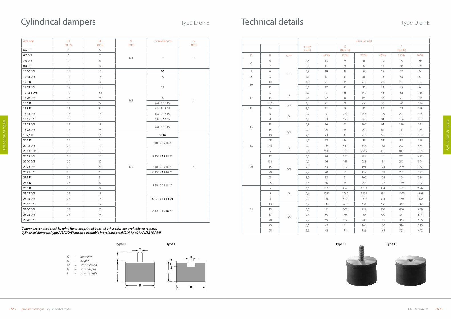
GMT Benelux BV • 69 •• 68 • product catalogue | cylindrical dampers
Cylin
dric
al d
ampe
rs
Cylin
dric
al d
ampe
rs
technical details type D en E
Pressure load
s max (mm)
C (N/mm)
F max (N)
D H type 40°Sh 55°Sh 70°Sh 40°Sh 55°Sh 70°Sh
66
D/E
0,8 13 25 41 10 19 30
7 0,9 11 20 32 10 18 29
7 6 0,8 19 36 58 15 27 44
8 8 1,1 17 31 51 18 33 53
1010 1,3 21 39 63 28 51 83
15 2,1 12 22 36 24 45 74
12
8D
1,0 47 86 140 48 88 143
13 1,8 22 40 65 38 71 115
13,5D/E
1,8 21 38 62 38 70 114
13 26 3,7 11 19 32 39 72 118
15
6D
0,7 151 279 453 109 201 326
8 1,0 83 153 248 84 156 253
13
D/E
1,8 36 67 109 64 119 194
15 2,1 29 55 89 61 113 184
18 2,5 23 42 69 58 107 174
28 4,0 13 24 39 53 97 158
18 7,5D
0,9 185 342 555 158 292 474
20
5 0,5 980 1818 2945 441 817 1325
12
D/E
1,5 94 174 283 141 262 425
13,5 1,7 76 141 228 131 243 394
15 2,0 63 117 191 124 229 372
20 2,7 40 75 122 109 202 329
23 3,2 33 61 100 104 194 314
25 3,5 30 55 89 102 189 307
25
5
D
0,5 2075 3843 6238 934 1729 2807
6 0,6 1052 1949 3163 631 1169 1898
8 0,9 438 812 1317 394 730 1186
13
D/E
1,7 144 268 434 238 442 717
15 2,0 111 205 333 216 400 649
17 2,3 89 165 268 200 371 603
20 2,7 69 127 206 185 343 556
25 3,5 49 91 148 170 314 510
28 3,9 42 78 126 164 303 492
type D type E
Cylindrical dampers type D en E
Art.Code D (mm)
H (mm)
M (mm)
L Screw length G(mm)
6 6 D/E 6 6
M3 6 36 7 D/E 6 7
7 6 D/E 7 6
8 8 D/E 8 8
10 10 D/E 10 10
M4
10
4
10 15 D/E 10 15 10
12 8 D 12 8
12 12 13 D/E 12 13
12 13,5 D/E 12 13,5
13 26 D/E 13 26 10
15 6 D 15 6 6 8 10 13 15
15 8 D 15 8 6 8 10 13 15
15 13 D/E 15 13 6 8 10 13 15
15 15 D/E 15 15 6 8 10 13 15
15 18 D/E 15 186 8 10 13 15
15 28 D/E 15 28
18 7,5 D 18 7,5
M6
10 16
6
20 5 D 20 58 10 12 15 18 20
20 12 D/E 20 12
20 13,5 D/E 20 13,5
8 10 12 15 18 20 20 15 D/E 20 15
20 20 D/E 20 20
20 23 D/E 20 23 8 10 12 15 18 20
20 25 D/E 20 25 8 10 12 15 18 20
25 5 D 25 5
8 10 12 15 18 2025 6 D 25 6
25 8 D 25 8
25 13 D/E 25 13
25 15 D/E 25 15 8 10 12 15 18 20
8 10 12 15 18 20
25 17 D/E 25 17
25 20 D/E 25 20
25 25 D/E 25 25
25 28 D/E 25 28
Column L: standard stock keeping items are printed bold, all other sizes are available on request.Cylindrical dampers (type A/B/C/D/E) are also available in stainless steel (DIN 1.4401 / AISI 316 / A4)
D = diameterH = heightM = screw threadG = screw depthL = screw length
L
H
M
H
M
G
type D type E
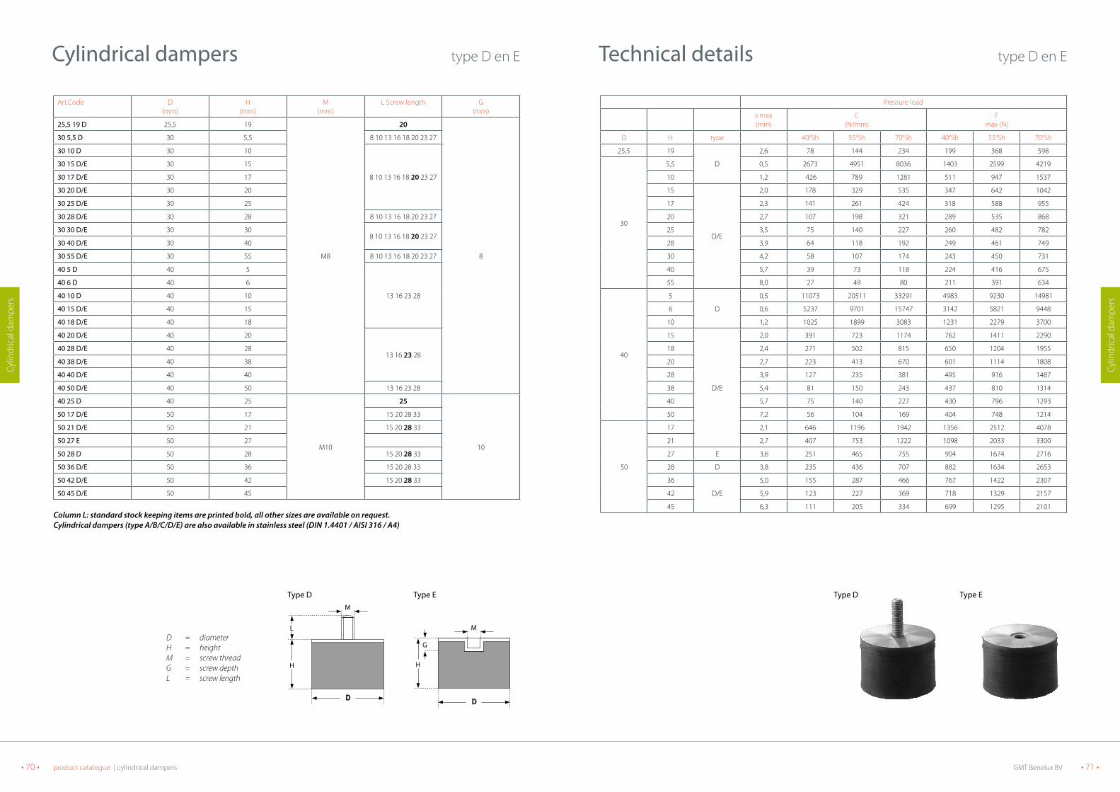
GMT Benelux BV • 71 •• 70 • product catalogue | cylindrical dampers
Cylin
dric
al d
ampe
rs
Cylin
dric
al d
ampe
rs
technical details type D en E
Pressure load
s max (mm)
C (N/mm)
F max (N)
D H type 40°Sh 55°Sh 70°Sh 40°Sh 55°Sh 70°Sh
25,5 19
D
2,6 78 144 234 199 368 598
30
5,5 0,5 2673 4951 8036 1403 2599 4219
10 1,2 426 789 1281 511 947 1537
15
D/E
2,0 178 329 535 347 642 1042
17 2,3 141 261 424 318 588 955
20 2,7 107 198 321 289 535 868
25 3,5 75 140 227 260 482 782
28 3,9 64 118 192 249 461 749
30 4,2 58 107 174 243 450 731
40 5,7 39 73 118 224 416 675
55 8,0 27 49 80 211 391 634
40
5
D
0,5 11073 20511 33291 4983 9230 14981
6 0,6 5237 9701 15747 3142 5821 9448
10 1,2 1025 1899 3083 1231 2279 3700
15
D/E
2,0 391 723 1174 762 1411 2290
18 2,4 271 502 815 650 1204 1955
20 2,7 223 413 670 601 1114 1808
28 3,9 127 235 381 495 916 1487
38 5,4 81 150 243 437 810 1314
40 5,7 75 140 227 430 796 1293
50 7,2 56 104 169 404 748 1214
50
17 2,1 646 1196 1942 1356 2512 4078
21 2,7 407 753 1222 1098 2033 3300
27 E 3,6 251 465 755 904 1674 2716
28 D 3,8 235 436 707 882 1634 2653
36
D/E
5,0 155 287 466 767 1422 2307
42 5,9 123 227 369 718 1329 2157
45 6,3 111 205 334 699 1295 2101
type D type E
Cylindrical dampers type D en E
Art.Code D (mm)
H (mm)
M (mm)
L Screw length G(mm)
25,5 19 D 25,5 19
M8
20
8
30 5,5 D 30 5,5 8 10 13 16 18 20 23 27
30 10 D 30 10
8 10 13 16 18 20 23 27
30 15 D/E 30 15
30 17 D/E 30 17
30 20 D/E 30 20
30 25 D/E 30 25
30 28 D/E 30 28 8 10 13 16 18 20 23 27
30 30 D/E 30 308 10 13 16 18 20 23 27
30 40 D/E 30 40
30 55 D/E 30 55 8 10 13 16 18 20 23 27
40 5 D 40 5
13 16 23 28
40 6 D 40 6
40 10 D 40 10
40 15 D/E 40 15
40 18 D/E 40 18
40 20 D/E 40 20
13 16 23 2840 28 D/E 40 28
40 38 D/E 40 38
40 40 D/E 40 40
40 50 D/E 40 50 13 16 23 28
40 25 D 40 25
M10
25
10
50 17 D/E 50 17 15 20 28 33
50 21 D/E 50 21 15 20 28 33
50 27 E 50 27
50 28 D 50 28 15 20 28 33
50 36 D/E 50 36 15 20 28 33
50 42 D/E 50 42 15 20 28 33
50 45 D/E 50 45
Column L: standard stock keeping items are printed bold, all other sizes are available on request.Cylindrical dampers (type A/B/C/D/E) are also available in stainless steel (DIN 1.4401 / AISI 316 / A4)
D = diameterH = heightM = screw threadG = screw depthL = screw length
L
H
M
H
M
G
type D type E
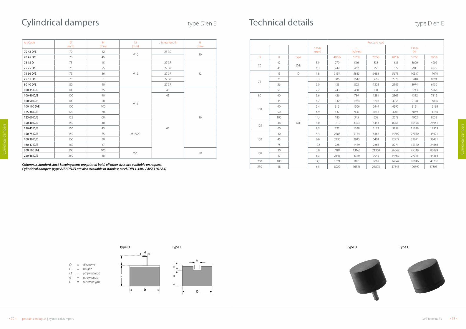
GMT Benelux BV • 73 •• 72 • product catalogue | cylindrical dampers
Cylin
dric
al d
ampe
rs
Cylin
dric
al d
ampe
rs
technical details type D en E
Pressure load
s max (mm)
C (N/mm)
F max (N)
D H type 40°Sh 55°Sh 70°Sh 40°Sh 55°Sh 70°Sh
70 42
D/E5,9 279 516 838 1631 3020 4902
45 6,3 249 462 750 1572 2911 4725
75
15 D 1,8 3154 5843 9483 5678 10517 17070
25
D/E
3,3 886 1642 3665 2925 5418 8794
36 5,0 433 803 1303 2145 3974 6450
51 7,2 243 450 731 1751 3243 5263
80 40 5,6 426 789 1281 2365 4382 7112
100
35 4,7 1066 1974 3203 4955 9178 14896
40 5,4 813 1506 2444 4390 8131 13198
50 6,9 537 996 1616 3708 6869 11150
100 14,4 186 345 559 2679 4962 8053
12538 5,0 1810 3353 5443 8961 16598 26941
60 8,3 722 1338 2172 5959 11038 17915
150
40 5,3 2783 5154 8366 14609 27060 43921
45 6,0 2130 3945 6404 12779 23671 38421
75 10,5 788 1459 2368 8271 15320 24866
16030 3,8 7104 13160 21360 26642 49349 80099
47 6,3 2343 4340 7045 14762 27345 44384
200 100 14,3 1021 1891 3069 14547 26946 43736
250 48 6,5 8922 16526 26823 57545 106592 173011
type D type E
Cylindrical dampers type D en E
Art.Code D (mm)
H (mm)
M (mm)
L Screw length G(mm)
70 42 D/E 70 42 M10
25 30 10
70 45 D/E 70 45
75 15 D 75 15
M12
27 37
12
75 25 D/E 75 25 27 37
75 36 D/E 75 36 27 37
75 51 D/E 75 51 27 37
80 40 D/E 80 40 27 37
100 35 D/E 100 35
M16
45
16
100 40 D/E 100 40 45
100 50 D/E 100 50
45
100 100 D/E 100 100
125 38 D/E 125 38
125 60 D/E 125 60
150 40 D/E 150 40
M16/20
150 45 D/E 150 45
150 75 D/E 150 75
160 30 D/E 160 30
160 47 D/E 160 47
200 100 D/E 200 100M20 20
250 48 D/E 250 48
Column L: standard stock keeping items are printed bold, all other sizes are available on request.Cylindrical dampers (type A/B/C/D/E) are also available in stainless steel (DIN 1.4401 / AISI 316 / A4)
D = diameterH = heightM = screw threadG = screw depthL = screw length
L
H
M
H
M
G
type D type E
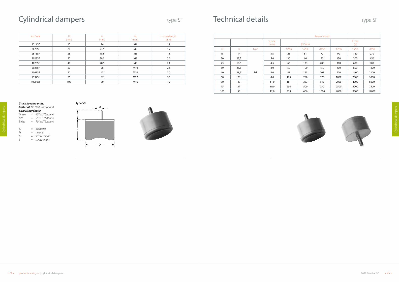
GMT Benelux BV • 75 •• 74 • product catalogue | cylindrical dampers
Cylin
dric
al d
ampe
rs
Cylin
dric
al d
ampe
rs
Pressure load
s max [mm]
C (N/mm)
F max (N)
D H type 40°Sh 55°Sh 70°Sh 40°Sh 55°Sh 70°Sh
15 14 3,5 25 51 77 90 180 270
20 23,5 5,0 30 60 90 150 300 450
25 18,5 4,5 66 133 200 300 600 900
30 28,5 8,0 50 100 150 400 800 1200
40 28,5 S/F 8,0 87 175 263 700 1400 2100
50 28 8,0 125 250 375 1000 2000 3000
70 43 11,0 181 363 545 2000 4000 6000
75 37 10,0 250 500 750 2500 5000 7500
100 50 12,0 333 666 1000 4000 8000 12000
technical details type SF
Stock keeping units:Material: NR (Natural Rubber)Colour/hardness:Green = 40° ± 5° Shore ARed = 55° ± 5° Shore ABeige = 70° ± 5° Shore A
D = diameterH = heightM = screw threadL = screw length
Art.Code D(mm)
H(mm)
M(mm)
L screw length(mm)
1514SF 15 14 M4 13
2023SF 20 23,5 M6 15
2518SF 25 18,5 M6 18
3028SF 30 28,5 M8 20
4028SF 40 28,5 M8 23
5028SF 50 28 M10 28
7043SF 70 43 M10 30
7537SF 75 37 M12 37
10050SF 100 50 M16 45
Cylindrical dampers type SF
L
H
D
Mtype S/F
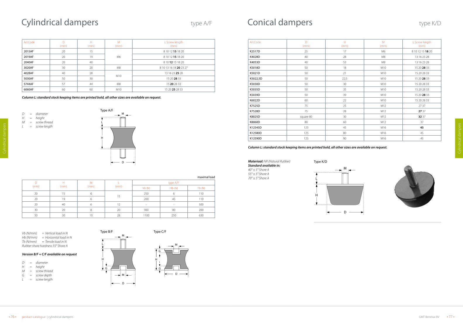
GMT Benelux BV • 77 •• 76 • product catalogue | cylindrical dampers
Cylin
dric
al d
ampe
rs
Cylin
dric
al d
ampe
rs
Art.Code D (mm)
H (mm)
M (mm)
L Screw length(mm)
K2517D 25 17 M6 8 10 12 15 18 20
K4028D 40 28 M8 13 16 23 28
K4053D 40 53 M8 13 16 23 28
K5018D 50 18 M10 15 20 28 33
K5021D 50 21 M10 15 20 28 33
K5022,5D 50 22,5 M10 15 20 28 33
K5030D 50 30 M10 15 20 28 33
K5035D 50 35 M10 15 20 28 33
K5039D 50 39 M10 15 20 28 33
K6022D 60 22 M10 15 20 28 33
K7525D 75 25 M12 27 37
K7528D 75 28 M12 27 37
K8025D square 80 30 M12 32 37
K8060D 80 60 M12 37
K12545D 125 45 M16 45
K12580D 125 80 M16 45
K12590D 125 90 M16 45
Column L: standard stock keeping items are printed bold, all other sizes are available on request.
Conical dampers type K/D
L
H
D
M
Materiaal: NR (Natural Rubber)Standard available in:40° ± 5° Shore A55° ± 5° Shore A70° ± 5° Shore A
type K/D
Art.Code D(mm)
H(mm)
M(mm)
L Screw length(mm)
2015AF 20 15 8 10 12 15 18 20
2019AF 20 19 M6 8 10 12 15 18 20
2040AF 20 40 8 10 12 15 18 20
3020AF 30 20 M8 8 10 13 16 18 20 23 27
4028AF 40 28M10
13 16 23 25 28
5030AF 50 30 15 20 28 33
5744AF 57 44 M8 15 20 28 33
6060AF 60 60 M10 15 20 25 28 33
Column L: standard stock keeping items are printed bold, all other sizes are available on request.
maximal load
D(mm)
H(mm)
M(mm)
L(mm)
type A/F
Vb (N) Hb (N) Tb (N)
20 15 615
250 6 110
20 19 6 200 45 110
20 40 6 12 - - 500
30 20 8 20 360 80 200
50 30 10 28 1100 250 630
Cylindrical dampers type A/F
L
H
D
MD = diameterH = heightM = screw threadL = screw length
Vb (N/mm) = Vertical load in NHb (N/mm) = Horizontal load in NTb (N/mm) = Tensile load in NRubber shore hardness 55° Shore A
Version B/F + C/F available on request
D = diameterH = heightM = screw threadG = screw depthL = screw length
D
M
M
G
L
H H
D
M
G
G
type A/F
type B/F type C/F

GMT Benelux BV • 79 •• 78 • product catalogue | cylindrical dampers
Cylin
dric
al d
ampe
rs
Cylin
dric
al d
ampe
rs
Material: NR (Natural Rubber)Standard available in:40° ± 5° Shore A55° ± 5° Shore A70° ± 5° Shore A
Art.Code D(mm)
H(mm)
M(mm)
G(mm)
K2517E 25 17 M6i 6
K4028E 40 28M8i
8
K4053E 40 53 8
K5018E 50 18
M10i
10
K5021E 50 21 10
K5022,5E 50 22,5 10
K5030E 50 30 10
K5035E 50 35 10
K5039E 50 39 10
K6022E 60 22 10
K7525E 75 25
M12i
12
K7528E 75 28 12
K8025E square 80 30 12
K8060E 80 60 12
K12545E 125 45
M16i
16
K12580E 125 80 16
K12590E 125 90 16
Column L: standard stock keeping items are printed bold, all other sizes are available on request.
Conical dampers type K/E
H
D
M
G
deflection (mm)
10 20 30 400
3000
6000
9000
12000 40 ° Sh A55 ° Sh A70 ° Sh A
forc
e (N
)
5 10 15 200
1000
2000
3000
4000 40 ° Sh A55 ° Sh A70 ° Sh A
deflection (mm)
forc
e (N
)
deflection (mm)
10 20 30 50400
10000
20000
30000
40 ° Sh A
55 ° Sh A70 ° Sh A
forc
e (N
)
type K/E
type K5035E
type K8060E
type K12590E
technical details type K/D
4 8 12 0
5000
10000
15000
20000 40°Sh A55°Sh A
70°Sh A
deflection (mm)
forc
e (N
)
6 82 4 10 12 140
1000
2000
5000
4000
3000
6000
40°Sh A
55°Sh A
70°Sh A
deflection (mm)
forc
e (N
)
3 6 90
250
500
750
100040°Sh A
55°Sh A70°Sh A
deflection (mm)
forc
e (N
)
forc
e (N
)
42 6 8 10 120
5000
10000
25000
20000
15000
30000
40°Sh A
55°Sh A
70°Sh A
deflection (mm)
forc
e (N
)
2 4 6 0
1250
2500
3750
5000
40°Sh A55°Sh A70°Sh A
deflection (mm)
5 10 15 20 0
12500
25000
37500
50000
40° Sh A
55° Sh A70° Sh A
deflection (mm)
forc
e (N
)
6 842 1 0 1 2 1 4 1 6 1 8 2 00
2000
4000
10000
8000
6000
12000
40° Sh A
55° Sh A
70° Sh A
deflection (mm)
forc
e (N
)
type K2517D
type K5018D type K5022,5D type K5039D
type K7528D type K8025D type K12545D
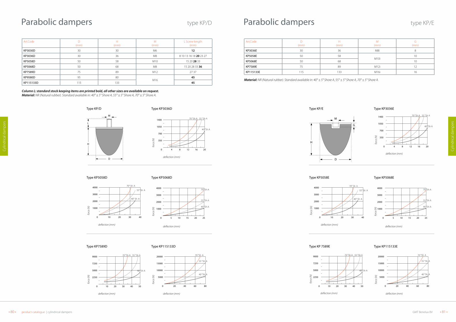
GMT Benelux BV • 81 •• 80 • product catalogue | cylindrical dampers
Cylin
dric
al d
ampe
rs
Cylin
dric
al d
ampe
rs
Art.Code D (mm)
H (mm)
M (mm)
G(mm)
KP3036E 30 36 M8i 8
KP5058E 50 58 M10i
10
KP5068E 50 68 10
KP7589E 75 89 M12i 12
KP115133E 115 133 M16i 16
Material: NR (Natural rubber). Standard available in: 40° ± 5° Shore A, 55° ± 5° Shore A, 70° ± 5° Shore A.
Parabolic dampers type KP/E
D
H
M
G
20 40 60 800
5000
10000
15000
20000
40 ° Sh A
55 ° Sh A
70 ° Sh A
deflection (mm)
forc
e (N
)
deflection (mm)
5 10 15 25200
1000
2000
3000
4000
40 ° Sh A
55 ° Sh A
70 ° Sh A
forc
e (N
)
type KP5068E
type KP/E
4 8 12 20160
350
700
1050
1400
40 ° Sh A
55 ° Sh A70 ° Sh A
deflection (mm)
forc
e (N
)
type KP3036E
deflection (mm)
10 20 30 50400
2250
5000
7250
9000
40 ° Sh A
55 ° Sh A70 ° Sh A
forc
e (N
)
type KP 7589E type KP115133E
10 20 30 400
1000
2000
3000
4000
40° Sh A
55° Sh A
70° Sh A
deflection (mm)
forc
e (N
)
type KP5058E
Parabolic dampers type KP/D
Art.Code D (mm)
H (mm)
M (mm)
L Screw length(mm)
KP3030D 30 30 M6 12
KP3036D 30 36 M8 8 10 13 16 18 20 23 27
KP5058D 50 58 M10 15 20 28 33
KP5068D 50 68 M8 15 20 28 33 36
KP7589D 75 89 M12 27 37
KP9580D 95 80M16
45
KP115133D 115 133 45
Column L: standard stock keeping items are printed bold, all other sizes are available on request.Material: NR (Natural rubber). Standard available in: 40° ± 5° Shore A, 55° ± 5° Shore A, 70° ± 5° Shore A.
D
L
H
M
type KP/D
4 8 12 20160
350
700
1050
1400
40 ° Sh A
55 ° Sh A70 ° Sh A
deflection (mm)
forc
e (N
)
type KP3036D
10 20 30 400
1000
2000
3000
4000
40° Sh A
55° Sh A
70° Sh A
deflection (mm)
forc
e (N
)
type KP5058D
deflection (mm)
5 10 15 25200
1000
2000
3000
4000
40 ° Sh A
55 ° Sh A
70 ° Sh A
forc
e (N
)
type KP5068D
deflection (mm)
10 20 30 50400
2250
5000
7250
9000
40 ° Sh A
55 ° Sh A70 ° Sh A
forc
e (N
)
type KP7589D
20 40 60 800
5000
10000
15000
20000
40 ° Sh A
55 ° Sh A
70 ° Sh A
deflection (mm)
forc
e (N
)
type KP115133D

GMT Benelux BV • 83 •• 82 • product catalogue | miscellaneous dampers
Mis
cella
neou
s da
mpe
rs
Mis
cella
neou
s da
mpe
rs
technical details crane/stop buffers
10 20 30 400
10
20
30
40
50
60
70
deflection (mm)
forc
e (k
N)
Diameter 100
10 20 30 40 500
20
40
80
100
60
deflection (mm)
forc
e (k
N)
Diameter 125
5 1 0 1 5 2 002468
10121416
deflection (mm)
forc
e (k
N)
Diameter 50
4 8 12 160
2
4
8
10
6
deflection (mm)
forc
e (k
N)
Diameter 40
8 1 6 2 4 3 205
10152025303540
deflection (mm)
forc
e (k
N)
Diameter 80
5 1 0 1 5 2 0 2 50
5
10
20
25
15
deflection (mm)
forc
e (k
N)
Diameter 63
10 20 30 40 8050 60 700
50
100
200
250
150
deflection (mm)
forc
e (k
N)
Diameter 200
10 20 4030 50 60 700
20406080
120
160140
100
deflection (mm)
forc
e (k
N)
Diameter 160
20 40 60 80 1000
50100150200250300350400
deflection (mm)
forc
e (k
N)
Diameter 250
Material: NR (Natural Rubber)Standard available in 70° ± 5° Shore A
H = heightM = screw threadD = diameterL = width base plateLs = spacing mounting holesd = diameter bore diameterS = plate thicknessR = radius
Crane buffer with base plate
Art.Code D (mm)
H (mm)
Base plate sizeL (mm)
S (mm)
d (mm)
Ls (mm)
R(mm)
55490170 40 34 50 2 5,5 40 8
55490270 50 42 63 26,5
50 10
55490370 63 53 80 3 63 12,5
55490470 80 66 100 39,0
80 16
55490570 100 84 125 4 100 20
55490670 125 104 160 411
125 25
55490770 160 131 200 6 160 32
55490870 200 166 250 613
200 40
55490970 250 208 315 8 250 50
Crane buffer with screw thread
Art.Code D(mm)
H(mm)
M(mm)
L(mm)
R(mm)
55190070 40 34 M8 28 8
55190170 50 42M10
33 10
55190270 63 53 32 12,5
55190370 80 66M12
37 16
55190470 100 84 36 20
55190570 125 104M16
46 25
55190670 160 131 44 32
55190770 200 166M20
49 40
55190870 250 208 47 50
Crane/Stop buffers
L
Ls
d
L
Crane buffer with base plate
L
H
D
M
Crane bufferwith screw thread
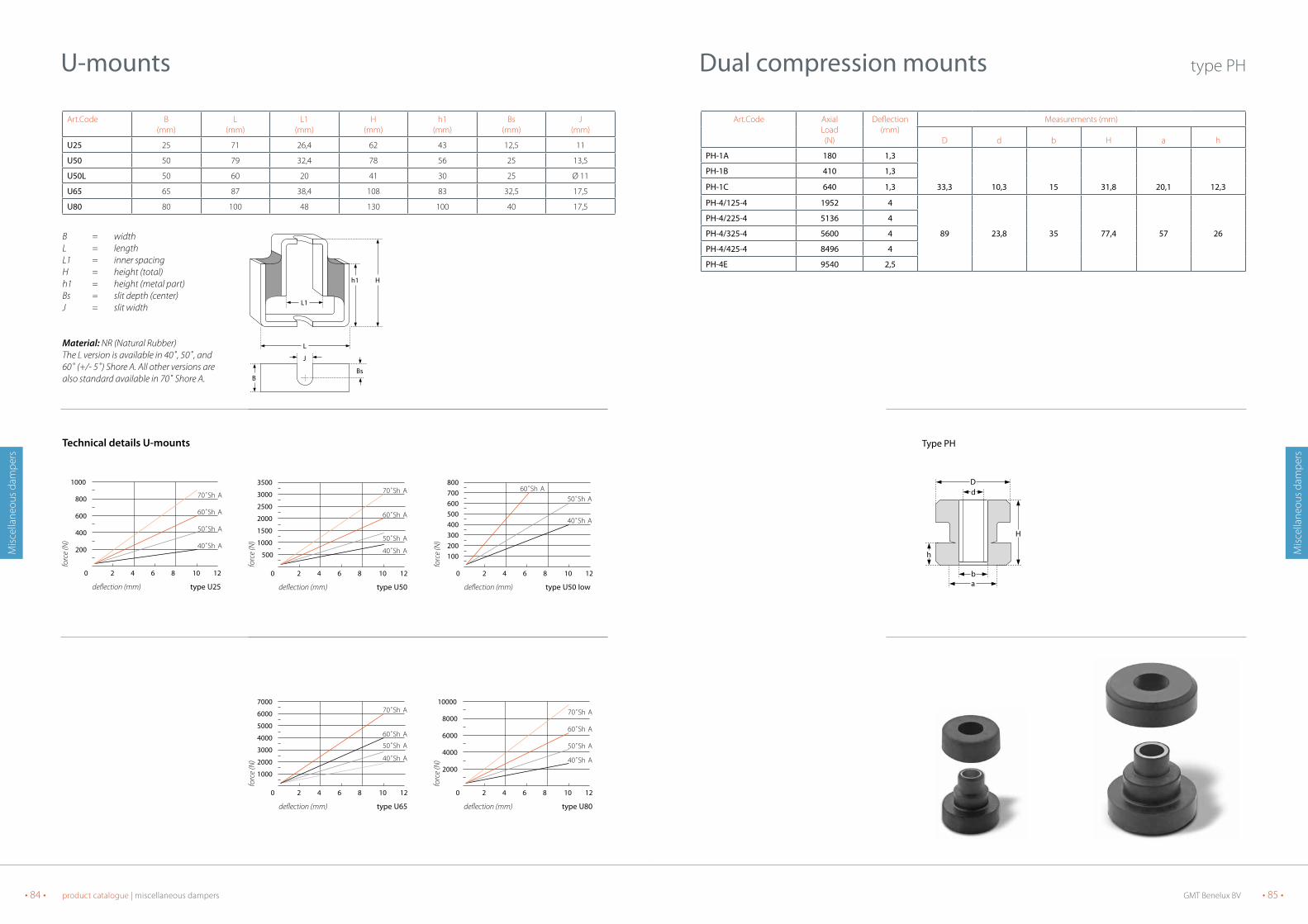
GMT Benelux BV • 85 •• 84 • product catalogue | miscellaneous dampers
Mis
cella
neou
s da
mpe
rs
Mis
cella
neou
s da
mpe
rs
Art.Code Axial Load(N)
Deflection (mm)
Measurements (mm)
D d b H a h
PH-1A 180 1,3
PH-1B 410 1,3
PH-1C 640 1,3 33,3 10,3 15 31,8 20,1 12,3
PH-4/125-4 1952 4
PH-4/225-4 5136 4
PH-4/325-4 5600 4 89 23,8 35 77,4 57 26
PH-4/425-4 8496 4
PH-4E 9540 2,5
Dual compression mounts type PH
a
d
b
D
H
h
type PH
B = widthL = lengthL1 = inner spacingH = height (total)h1 = height (metal part)Bs = slit depth (center)J = slit width
Material: NR (Natural Rubber)The L version is available in 40˚, 50˚, and60˚ (+/- 5˚) Shore A. All other versions arealso standard available in 70˚ Shore A.
Art.Code B(mm)
L(mm)
L1(mm)
H(mm)
h1(mm)
Bs(mm)
J(mm)
U25 25 71 26,4 62 43 12,5 11
U50 50 79 32,4 78 56 25 13,5
U50L 50 60 20 41 30 25 Ø 11
U65 65 87 38,4 108 83 32,5 17,5
U80 80 100 48 130 100 40 17,5
U-mounts
L
H
L1
J
BsB
h1
2 4 6 8 10 120
3500
3000
2500
2000
1500
1000
500
50˚Sh A
40˚Sh A
60˚Sh A
70˚Sh A
deflection (mm) type U50
forc
e (N
)
2 4 6 8 10 120
1000
800
600
400
200
50˚Sh A
40˚Sh A
60˚Sh A
70˚Sh A
deflection (mm) type U25
forc
e (N
)
2 4 6 8 10 120
800700600500400300200100
50˚Sh A
40˚Sh A
60˚Sh A
deflection (mm) type U50 low
forc
e (N
)
2 4 6 8 10 120
7000
6000
5000
4000
3000
2000
1000
50˚Sh A
40˚Sh A
60˚Sh A
70˚Sh A
deflection (mm) type U65
forc
e (N
)
2 4 6 8 10 120
10000
8000
6000
4000
2000
50˚Sh A
40˚Sh A
60˚Sh A
70˚Sh A
deflection (mm) type U80
forc
e (N
)Technical details U-mounts
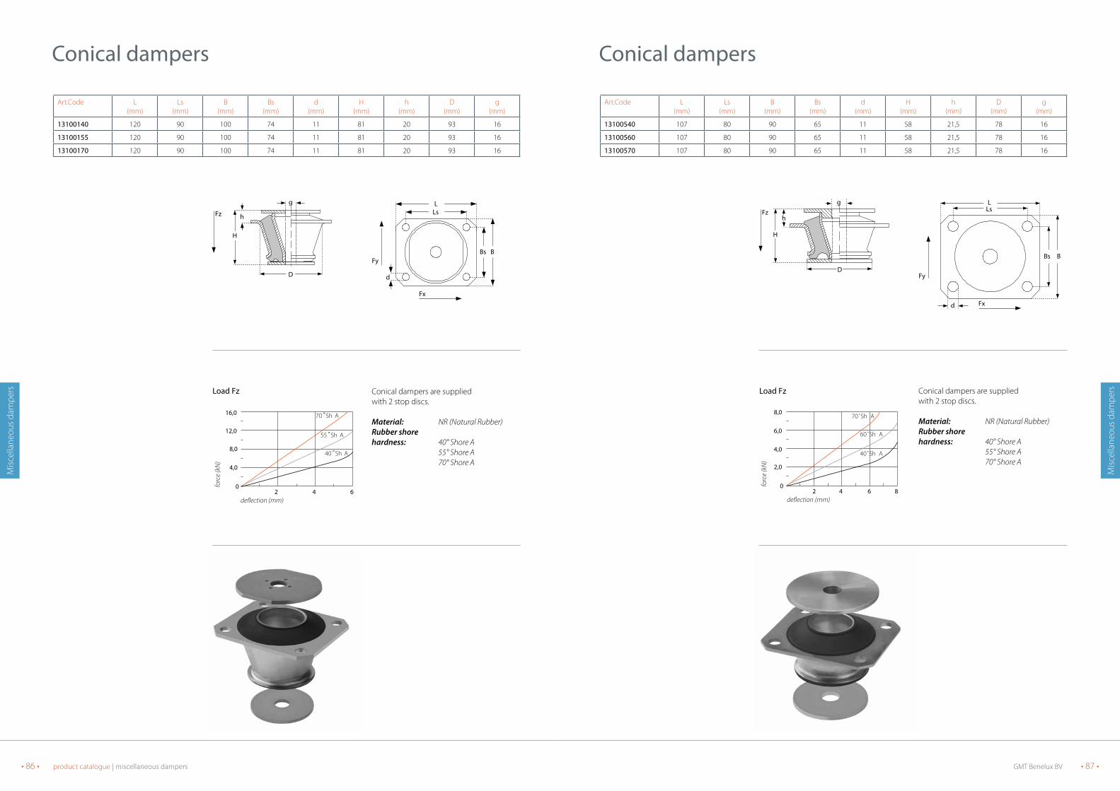
GMT Benelux BV • 87 •• 86 • product catalogue | miscellaneous dampers
Mis
cella
neou
s da
mpe
rs
Mis
cella
neou
s da
mpe
rsConical dampers are suppliedwith 2 stop discs.
Material: NR (Natural Rubber)Rubber shore hardness: 40° Shore A 55° Shore A 70° Shore A
Art.Code L(mm)
Ls(mm)
B(mm)
Bs(mm)
d(mm)
H(mm)
h(mm)
D(mm)
g(mm)
13100540 107 80 90 65 11 58 21,5 78 16
13100560 107 80 90 65 11 58 21,5 78 16
13100570 107 80 90 65 11 58 21,5 78 16
Conical dampers
Fzh
H
g
DFy
d Fx
L
Bs B
Ls
2 4 6 80
2,0
4,0
8,0
6,0
70˚Sh A
60˚Sh A
40˚Sh A
deflection (mm)
forc
e (k
N)
Load FzConical dampers are suppliedwith 2 stop discs.
Material: NR (Natural Rubber)Rubber shore hardness: 40° Shore A 55° Shore A 70° Shore A
Art.Code L(mm)
Ls(mm)
B(mm)
Bs(mm)
d(mm)
H(mm)
h(mm)
D(mm)
g(mm)
13100140 120 90 100 74 11 81 20 93 16
13100155 120 90 100 74 11 81 20 93 16
13100170 120 90 100 74 11 81 20 93 16
Conical dampers
Fz
g
h
H
D
Fy
Fx
L
d
Ls
Bs B
2 4 60
4,0
8,0
16,0
12,0
70 °Sh A
55 °Sh A
40 °Sh A
deflection (mm)
forc
e (k
N)
Load Fz
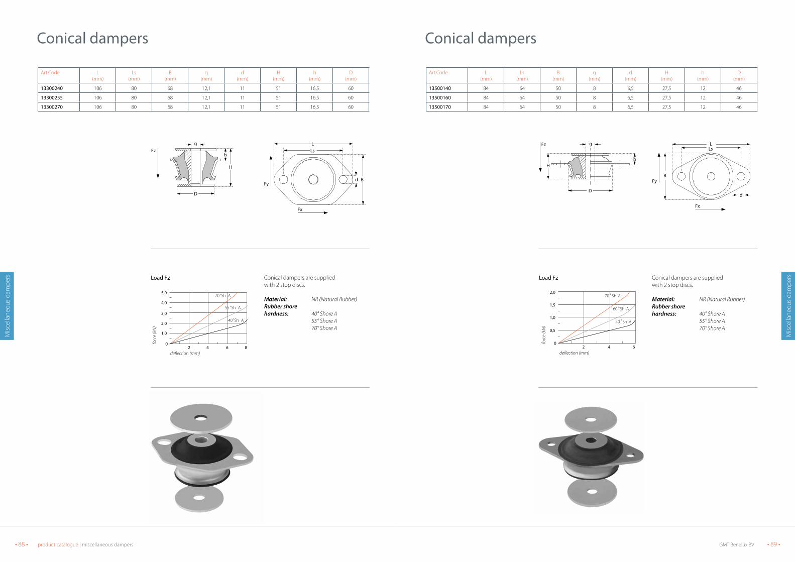
GMT Benelux BV • 89 •• 88 • product catalogue | miscellaneous dampers
Mis
cella
neou
s da
mpe
rs
Mis
cella
neou
s da
mpe
rsConical dampers are suppliedwith 2 stop discs.
Material: NR (Natural Rubber)Rubber shore hardness: 40° Shore A 55° Shore A 70° Shore A
Art.Code L(mm)
Ls(mm)
B(mm)
g(mm)
d(mm)
H(mm)
h(mm)
D(mm)
13500140 84 64 50 8 6,5 27,5 12 46
13500160 84 64 50 8 6,5 27,5 12 46
13500170 84 64 50 8 6,5 27,5 12 46
Conical dampers
Fz g
H
D
h
Fy
Fx
LLs
B
d
2 4 60
0,5
1,0
2,0
1,5
70 °Sh A
60 °Sh A
40 °Sh A
deflection (mm)
forc
e (k
N)
Load FzLoad FzConical dampers are suppliedwith 2 stop discs.
Material: NR (Natural Rubber)Rubber shore hardness: 40° Shore A 55° Shore A 70° Shore A
Art.Code L(mm)
Ls(mm)
B(mm)
g(mm)
d(mm)
H(mm)
h(mm)
D(mm)
13300240 106 80 68 12,1 11 51 16,5 60
13300255 106 80 68 12,1 11 51 16,5 60
13300270 106 80 68 12,1 11 51 16,5 60
Conical dampers
Fz
D
g
H
h
Fy
LLs
Fx
d B
2 4 6 80
1,0
2,0
4,0
5,0
3,0
70˚Sh A
55˚Sh A
40˚Sh A
deflection (mm)
forc
e (k
N)
Load Fz

GMT Benelux BV • 91 •• 90 • product catalogue | miscellaneous dampers
Mis
cella
neou
s da
mpe
rs
Mis
cella
neou
s da
mpe
rs• Robust construction• Fail safe if mounted with stop discs• Suitable for absorbing heavy loads and vibrations
Art.Code D(mm)
D1(mm)
D2(mm)
g(mm)
H(mm)
h(mm)
S(mm)
L(mm)
Ls(mm)
Bs(mm)
B(mm)
d(mm)
P1550A45 139 124 40 25 100 46 12,5 172 144 100 150 11
Conical dampers Heavy Duty
D2
D1
g
s
D
H
hFz
P1550A45
L
d
Ls
BBs
P1550A45
63 1 29 1 50
2500
7500
15000
10000
5000
deflection (mm)
forc
e (N
)
Load FzConical dampers are suppliedwith 2 stop discs.
Material: NR (Natural Rubber)Rubber shore hardness: 40° Shore A 55° Shore A 70° Shore A
Art.Code L(mm)
Ls(mm)
B(mm)
Bs(mm)
d(mm)
H(mm)
h(mm)
D(mm)
g(mm)
13600140 140 112 120 92 11 95 23 109 20
13600160 140 112 120 92 11 95 23 109 20
13600170 140 112 120 92 11 95 23 109 20
Conical dampers
Fz h
g
H
D
D
Fy
Fx
d
L
Bs B
Ls
2 4 860
4,0
8,0
16,0
20,0
24,0
12,0
70 °Sh A
60 °Sh A
40 °Sh A
deflection (mm)
forc
e (k
N)
Load Fz

GMT Benelux BV • 93 •• 92 • product catalogue | miscellaneous dampers
Mis
cella
neou
s da
mpe
rs
Mis
cella
neou
s da
mpe
rs
Art.Code. B(mm)
H(mm)
L(mm)
M(mm)
Ls(mm)
d(mm)
6411500240 64 30 115 M10i 85 10,5
6411500257 64 30 115 M10i 85 10,5
6411500270 64 30 115 M10i 85 10,5
Art.Code. H(mm)
C(mm)
A(mm)
M(mm)
L(mm)
535611 47 30 55 M8 13
Hanging elements
H
M
C
B
Ls
L
d
M
A
L
H
0,5 1 2 3 40
200
300
400
600
700
500
40 °Sh A
55 °Sh A
70 °Sh A
deflection (mm)
forc
e (N
)
1 2 3 40
100
200
300
500
400
45 Sh A
deflection (mm)
forc
e (N
)
Material: NR (Natural Rubber)Rubber shore hardness: 40° en 60° Shore A
Art.Code L(mm)
Ls(mm)
B(mm)
g(mm)
d(mm)
H(mm)
h(mm)
D(mm)
13201236 89 73 54 10,5 8,7 30 10,3 50
13201260 89 73 54 10,5 8,7 30 10,3 50
Conical dampers
Fzg
D
h
H
L
B
Ls
d
2,41,2 3,6 4,8 60
0,3
0,6
1,2
1,5
0,9
deflection (mm)
forc
e (k
N)
60˚
40˚
Load Fz

GMT Benelux BV • 95 •• 94 • product catalogue | miscellaneous dampers
Mis
cella
neou
s da
mpe
rs
Mis
cella
neou
s da
mpe
rs
Art.Code. B(mm)
H(mm)
L(mm)
M(mm)
Ls(mm)
d(mm)
64060014 35 20 60 M6 45 6
64090014 50 32 90 M10 70 9
64140014 80 50 140 M16 105 13
Hat elements
Material: NR (Natural Rubber)Standard available in:40° ± 5° Shore A55° ± 5° Shore A70° ± 5° Shore A
B = widthH = heightL = lengthM = screw thread sizeLs = spacing mounting holesd = diameter mounting hole
B
Ls
d M
L
H
deflection (mm)
forc
e (N
)
500
400
300
200
100
01 2 3 4 5
deflection (mm)
forc
e (N
)
700
600
500
400
300
200
01 2 3 4 5
deflection (mm)
forc
e (N
)
1 2 3 4 5
2200
1800
1300
900
400
0
type 64060014 type 64090014 type 64140014
D = diameterG = screw threadH = heightL = lengthB = widthLs = spacing mounting holesd = diameter mounting holeS = plate thickness
GMT isolators are designed for large isolation with small loads. They are mainly applied at low interfering frequencies. The isolators are available in 3 hardness’s (40˚, 55˚, 70˚ Shore A) and suitable for loads up to 4000N.For easy recognition the isolators are supplied in different colours.40˚ Shore A = Rubber colour is green55˚ Shore A = Rubber colour is red70˚ Shore A = Rubber colour is beige
Art.Code D(mm)
M(mm)
H(mm)
L(mm)
B(mm)
Ls(mm)
d(mm)
s(mm)
ISo1 32 M8i 32 80 45 60 9,0 6,0
ISo2 45 M10i 45 98 60 76 9,0 6,0
ISo3 63 M12i 73 140 86 105 14,0 6,5
Isolators
M
D
H
s
L
Ls
B
d
1,5 2 3 4 5 60
100
200
500
1000
40 °Sh A
55 °Sh A
70 °Sh A
deflection (mm)
forc
e (N
)
1,5 2 3 4 5 6 7 80
100
200
500
1000
2000
40 °Sh A
55 °Sh A
70 °Sh A
deflection (mm)
forc
e (N
)
1,5 2 3 4 5 6 7 8 9 100
100
200
500
1000
2000
3000
4000
40 °Sh A
55 °Sh A
70 °Sh A
deflection (mm)
forc
e (N
)
ISo1 ISo2 ISo3

GMT Benelux BV • 97 •• 96 • product catalogue | miscellaneous dampers
Mis
cella
neou
s da
mpe
rs
Mis
cella
neou
s da
mpe
rs
Art.Code L(mm)
Ls(mm)
M(mm)
d(mm)
s(mm)
D
76130001 130 108 M12 7 5 50
76255001 255 215 M16 14 6 125
76470001 470 406 M24x1,5 20 8 300
Bellows
MD
s
7590 ±1 0
L
Ls
d
2 4 6 8 10 120
2
3
5
6
4
5, 06, 0
4, 03, 0
2, 0
1, 0
load range (kN)
own
frequ
ency
(Hz)
pres
sure
(bar
)
0,5 1 1,5 2 2,5 30
2
3
5
6
4
5, 74, 93, 7
2, 6
1, 4
load range (kN)
own
frequ
ency
(Hz)
pres
sure
(bar
)
10 20 30 40 50 600
2
3
5
6
4
5, 64, 53, 5
2, 4
1, 3
load range (kN)
own
frequ
ency
(Hz)
pres
sure
(bar
)
type 76130001 type 76255001 type 7647001
Material: NR (Natural Rubber)available in hardness45° ± 5° shore A
B = widthH = heightL = length
Material: NR (Natural Rubber)available in hardness45° ± 5° shore Aoilresistant
B = widthH = heightL = length
Art.Code B(mm)
H(mm)
L(mm)
LP12525125 125 25 125
LP20025200 200 25 200
LP25025250 250 25 250
LP25025500 250 25 500
LP30025300 300 25 300
LP30030300 300 30 300
LP40023600 400 23 600
Art.Code B(mm)
H(mm)
L(mm)
Profiel
MAt5005001 500 10 500 Ribbed longitudinal and transverse
MAtLD 250 10 500 Ribbed longitudinal and transverse
MAtLDS 250 10 500 Ribbed longitudinal and transverse with metal inserts
MAtnoP 250 10 500 Single sided studded, other side plain
Damping plates with longitudinal bore diameter
Damping plates ribbed or studded
50403020
10
5
30,3 0,5 1 2 3 4 5 6 7 8
25 mm plate th
ickness
30 mm plate th
ickness
f (mm)
forc
e (N
/cm
2 )
1 2 3 4 50
10
20
40
50
303 layers
1 layer
2 layers
deflection (mm)
forc
e (N
/cm
2 )
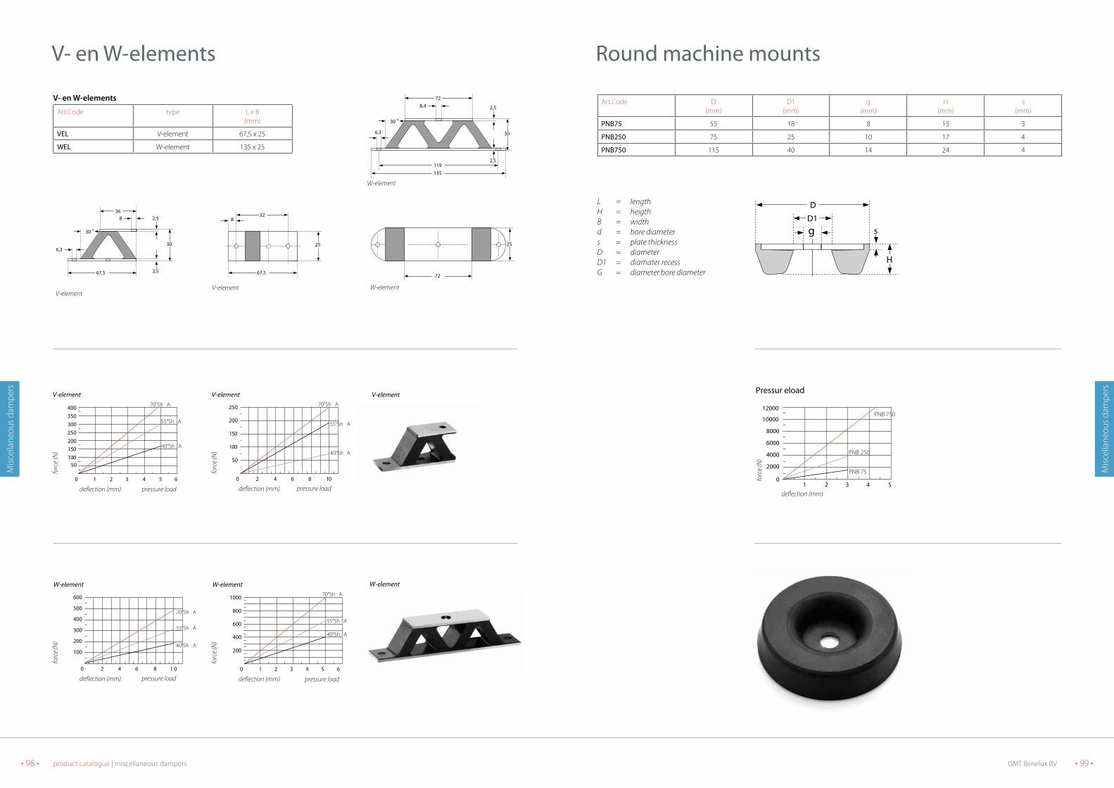
GMT Benelux BV • 99 •• 98 • product catalogue | miscellaneous dampers
Mis
cella
neou
s da
mpe
rs
Mis
cella
neou
s da
mpe
rs
Art.Code D(mm)
D1(mm)
g(mm)
H(mm)
s(mm)
PnB75 55 18 8 15 3
PnB250 75 25 10 17 4
PnB750 115 40 14 24 4
Round machine mounts
L = lengthH = heigthB = widthd = bore diameters = plate thicknessD = diameterD1 = diamater recessG = diameter bore diameter
D1g
D
s
H
21 43 50
2000
4000
8000
10000
12000
6000
PNB 750
PNB 250
PNB 75
deflection (mm)
forc
e (N
)
Pressur eload
21 3 4 650
100150200250300350400
50
40°Sh A
55°Sh A
70°Sh A
V-element
deflection (mm)
forc
e (N
)
pressure load
V- en W-elements
Art.Code type L x B(mm)
VEL V-element 67,5 x 25
WEL W-element 135 x 25
V- en W-elements
25
67,5
832
V-element
30
135
72
2,5
2,5
6,3
8,4
30 o
119
W-element
30
67,5
36
2,5
2,5
6,3
8
30 o
V-element
25
72
W-element
1 2 3 4 5 60
400
600
800
1000
200
40°Sh A
55°Sh A
70°Sh A
W-element
deflection (mm)
forc
e (N
)
pressure load
1 2 3 4 5 60
400
600
800
1000
200
40°Sh A
55°Sh A
70°Sh A
W-element
deflection (mm)
forc
e (N
)
pressure load
21 3 4 650
100150200250300350400
50
40°Sh A
55°Sh A
70°Sh A
V-element
deflection (mm)
forc
e (N
)
pressure load
2 4 6 8 1 00
200
300
400
500
600
10040°Sh A
55°Sh A
70°Sh A
W-element
deflection (mm)
forc
e (N
)
pressure load
102 4 6 80
50
100
150
200
250
40°Sh A
55°Sh A
70°Sh A
V-element
deflection (mm)
forc
e (N
)
pressure load

GMT Benelux BV • 101 •• 100 • Notes
NotesNotes
• 102 • Notes
Notes