CE Marking; ATEX, Machinery Directive, etc. – How to get it right
Upload
khangminh22Category
view
2download
0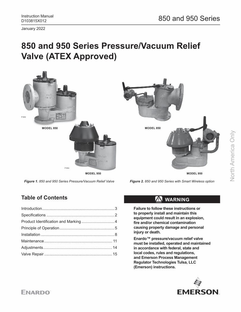
P1854
P1854
850 and 950 Series
Nor
th A
mer
ica
Onl
y
850 and 950 Series Pressure/Vacuum Relief Valve (ATEX Approved)
MODEL 850
MODEL 950 MODEL 950
MODEL 850
Figure 2. 850 and 950 Series with Smart Wireless optionFigure 1. 850 and 950 Series Pressure/Vacuum Relief Valve
Table of Contents
Introduction ..................................................................3Specifications ..............................................................2Product Identification and Marking ..............................4Principle of Operation ..................................................5Installation ...................................................................8Maintenance .............................................................. 11Adjustments ...............................................................14Valve Repair ..............................................................15
WARNINGFailure to follow these instructions or to properly install and maintain this equipment could result in an explosion, fire and/or chemical contamination causing property damage and personal injury or death.Enardo™ pressure/vacuum relief valve must be installed, operated and maintained in accordance with federal, state and local codes, rules and regulations, and Emerson Process Management Regulator Technologies Tulsa, LLC (Emerson) instructions.
January 2022
Instruction ManualD103815X012

2
850 and 950 Series
Nor
th A
mer
ica
Onl
y
SpecificationsThe Specifications section on this page provides specifications for the 850 and 950 Series pressure/vacuum relief valve. Specification is stamped on the nameplate attached to the relief valve. Refer to Product Identification and Marking section for the nameplate details.
Available ConstructionSee Figures 3 and 4
Inlet Connection Sizes2 through 12 in. / 50 through 300 mm
Pressure Ranges(1)(2)
0.4 to 32 oz./sq. in.1.0 to 55.0 in. w.c.1.72 to 138 mbar17.6 to 1406 mm w.c.
Vacuum Pressure Ranges(1)(2)
0.4 to 32.0 oz/sq. in.1.0 to 55.0 in. w.c.1.72 to 138 mbar17.6 to 1406 mm w.c.
Construction MaterialsHousing: Aluminum, Ductile iron, Stainless steel or Carbon steelSeat / Pallet: Polyphenylene Sulfide (PPS) or 316 Stainless steelPallet Seal: Buna-N, FEP Teflon® or Viton®
Hardware: Zinc-plated Carbon steel or Stainless steelWeights: Zinc-plated Carbon steel, Stainless steel or LeadGaskets: Buna-N, Teflon® or Viton®
CertificationEN IEC 60079-0:2018EN IEC 60079-11:2012EN ISO 80079-36:2016EN ISO 80079-37:2016
1. The pressure limits in this Instruction Manual and any applicable standard or code limitation should not be exceeded.2. Pressure or vacuum setting has an increment of 0.5 oz./sq. in., 0.5 in. w.c. or 2.2 mbar.
Model - Inlet Size x Outlet Size - Housing Material Pallet and Seat Material Pallet Seal Material Body/Seat/Lid Seal Material -
850 2 to 12 in. 3 to14 in. 1 = Aluminum2 = Ductile Iron4 = 316SST5 = Carbon Steel
1 = PPS Polyphenylene Sulfide2 = 316SST
1 = FEP2 = Nitrile (NBR)3 = Fluorocarbon (FKM)
1 = PTFE Body and FEP Seat/Lid
2 = Nitrile (NBR)3 = Fluorocarbon (FKM)
Pressure Units Pressure Setting / Vacuum Units Vacuum Setting - Weight Material - Options
z = oz./sq. in.n = in. w.c.mm = mm w.c.mb = mbar
0.5 to 32.0 oz./sq. in.0.86 to 55.0 in. w.c.22 to 1406 mm w.c.2.2 to 138 mbar
z = oz./sq. in.n = in. w.c.mm = mm w.c.mb = mbar
0.5 to 32.0 oz./sq. in.0.86 to 55.0 in. w.c.22 to 1406 mm w.c.2.2 to 138 mbar
C = CS ZPS = SSTL = Lead
0 = No OptionsF = Flat Face Flange (standard for Alumunim)R = Raised Face Flange (standard for CS, DI, SS)X = Epoxy CoatingW1 = Wireless Pressure and Vacuum MonitoringW2 = Wireless Pressure Monitoring OnlyW3 = Wireless Vacuum Monitoring OnlyW4 = Wired Pressure and Vacuum MonitoringW5 = Wired Pressure Monitoring OnlyW6 = Wired Vacuum Monitoring Only
MODEL 850 PRESSURE/VACUUM RELIEF VALVE MODEL NUMBER
MODEL 950 PRESSURE/VACUUM RELIEF VALVE MODEL NUMBER
Pressure Units Pressure Setting / Vacuum Units Vacuum Setting - Weight Material - Options
z = oz./sq. in.n = in. w.c.mm = mm w.c.mb = mbar
0.5 to 32.0 oz./sq. in.0.86 to 55.0 in. w.c.22 to 1406 mm w.c.2.2 to 138 mbar
z = oz./sq. in.n = in. w.c.mm = mm w.c.mb = mbar
0.5 to 32.0 oz./sq. in.0.86 to 55.0 in. w.c.22 to 1406 mm w.c.2.2 to 138 mbar
C = CS ZPS = SSTL = Lead
0 = No OptionsF = Flat Face Flange (standard for Alumunim)R = Raised Face Flange (standard for CS,DI, SS)X = Epoxy CoatingW1 = Wireless Pressure and Vacuum MonitoringW2 = Wireless Pressure Monitoring OnlyW3 = Wireless Vacuum Monitoring OnlyW4 = Wired Pressure and Vacuum MonitoringW5 = Wired Pressure Monitoring OnlyW6 = Wired Vacuum Monitoring Only
Figure 3. Pressure/Vacuum Relief Valve Model NumberTeflon® and Viton® are marks owned by E. I. du Pont de Nemours and Co.
Model - Inlet Size - Housing Material Pallet and Seat Material Pallet Seal Material Body/Seat/Lid Seal Material -
950 2 to 12 in. 1 = Aluminum2 = Ductile Iron4 = 316SST5 = Carbon Steel
1 = PPS Polyphenylene Sulfide2 = 316SST
1 = FEP2 = Nitrile (NBR)3 = Fluorocarbon (FKM)
1 = PTFE Body and FEP Seat/Lid2 = Nitrile (NBR)3 = Fluorocarbon (FKM)

3
850 and 950 Series
Nor
th A
mer
ica
Onl
y
Failure to correct trouble could result in a hazardous condition. Call a qualified service person to service the unit. Installation, operation and maintenance procedures performed by unqualified person may result in improper adjustment and unsafe operation. Either condition may result in equipment damage or personal injury. Only a qualified person shall install or service the pressure/vacuum relief valve.
Figure 4. 850 and 950 Series Pressure/Vacuum Relief Valve Available Models
MODEL 850 MODEL 850/MVC MODEL 851
MODEL 950 MODEL 951 MODEL 952
MODEL 952/MVC MODEL 953
Introduction
Scope of the ManualThis Instruction Manual provides instructions for installation, maintenance and parts ordering information for the 850 and 950 Series pressure/vacuum relief valve (PVRV).
Product Description
850 and 950 SeriesThe 850 and 950 Series pressure/vacuum relief valves provide protection against positive or vacuum overpressure and prevent air intake and evaporative losses of product while helping to contain odorous and potentially explosive vapors.
The 850 Series provides pressure and vacuum relief in applications that require hazardous vapors to be piped away rather than released into the atmosphere.
The 950 Series valve provides pressure and vacuum relief for normal venting requirements while maintaining a safe internal working pressure to prevent the routine expulsion of waste gas to the atmosphere.

4
850 and 950 Series
Nor
th A
mer
ica
Onl
y
• Model 850: Pressure/Vacuum Relief Valve — Pipe-Away
• Model 850/MVC: Marine Vapor Control System Pressure/Vacuum Relief Valve. This product is fitted with spark screens on the inlet and outlet ports in accordance with 33 CFR Part 154
• Model 851: Top Mount Pressure or Side Mount Vacuum Relief Valve — Pipe-Away
• Model 950: Pressure/Vacuum Relief Valve — Vent-to-Atmosphere
• Model 951: Pressure Relief Valve — Vent-to-Atmosphere
• Model 952: Top Mount Vacuum Relief Valve — End-of-Line
• Model 952/MVC: Marine Vapor Control System Vacuum Relief Valve
• Model 953: Side Mount Vacuum Relief Valve
Smart Wireless Monitoring OptionThe Smart Wireless Monitoring Option is available with PVRV Models 850 (Pipe-away) and 950 (Vent-to-atmosphere). This option allows the remote sensing and “OPEN/CLOSED” value transmission of the open or closed status of the pressure vent, the vacuum vent or both. Use Option Code WP for pressure vent monitoring, Option Code WV for vacuum vent monitoring or WPV for the monitoring of both at the end of the model string. Knowing whether a PVRV is open or closed can enable immediate response to prevent problems related to safety, emissions and quality of the tank contents.
The following are a few specific examples of how this added visibility can help prevent problems:
Example #1 – Redundant PVRVs
Redundant PVRVs are commonly used for added safety. If the primary PVRV fails closed or partially-closed, then the backup PVRV automatically takes over. This is achieved by establishing a pressure set point that is slightly higher for the backup device. In this way, if the primary PVRV fails, the tank remains protected. But redundancy is lost and should be addressed as soon as possible. But how will you know if this has occurred? Monitoring the open/closed position of the backup PVRV can provide quick identification of this issue, for either the pressure or vacuum side. Under normal conditions, the backup PVRV remains closed. If the backup PVRV is open, this points to either the primary PVRV not functioning
as expected or a separate pressure control problem in the tank system that is causing both PVRVs to be open. Ideally, the wireless monitoring of both primary and backup devices is preferred in order to gain the most insight. Further troubleshooting can then be performed and the problem can be detected and addressed.
Example #2 – Tank Blanketing
Tank blanketing is sometimes used in order to inert the vapor space in a tank for added safety. A tank blanketing regulator controls the inflow of nitrogen or another blanketing gas by responding to a low pressure set point. In this scenario, a PVRV (vacuum side) generally acts as a backup to the blanketing regulator. If the blanketing system fails for some reason, the PVRV automatically takes over, as its set point is slightly higher than that of the regulator. But once again, how is one to know that this has occurred? A wireless-monitored PVRV would indicate that the vacuum side is open. Under normal operation, it should be closed.
Example #3 – Emergency Vent
A storage tank’s emergency vent should remain closed, except in abnormal conditions. If an emergency vent is also remotely monitored, and found to be open, then there may be a pressure control issue somewhere in the system. In this scenario, the PVRV should also be open. If it is not, it could be part of the issue. Again, a wireless-monitored PVRV can readily provide this information.
Product Identification and Marking
Hazardous LocationsEnardo™ pressure/vacuum relief valves are available with outer housings of carbon steel, stainless steel or aluminum, as indicated in Figure 5.
NameplateA nameplate is attached to the valve and contains the following information:
• Model Number – Ex. 950-8-5211• Size – Ex. 8 in. • Serial Number• Tag Number (Optional)• Notified Body Number – Ex. 2460• Cat. No. (Category Number)
- Category 1 – Stainless steel, Carbon steel or Coated aluminum vents
- Category 2 – Uncoated aluminum vents

II 1 G Ex h IIC T6 Ga
II 2 G Ex h IIC T6 Gb
5
850 and 950 Series
Nor
th A
mer
ica
Onl
y• Date – Date of Manufacture• Certificate – Ex. PRESAFE 17 ATEX 10273X• Pressure Setting and Flow Rate
- Setting – Ex. Z4.0 - Flow Rate SCFH (Air) – Ex. 00000• Vacuum Setting and Flow Rate
- Setting – Ex. Z0.5 - Flow Rate SCFH (Air) – Ex. 00000
Principle of Operation850 and 950 SeriesThe 850 and 950 Series pressure/vacuum relief valves The 850 and 950 Series pressure/vacuum relief valves maintain a tight seal until system pressure or vacuum maintain a tight seal until system pressure or vacuum exceeds the set pressure of the valve. Set pressure exceeds the set pressure of the valve. Set pressure is determined by stacking a series of weights onto the is determined by stacking a series of weights onto the valve pallet unless the pressure and vacuum set points valve pallet unless the pressure and vacuum set points have been specified for the minimum settings. When have been specified for the minimum settings. When overpressure occurs, the weighted pallet lifts, breaking overpressure occurs, the weighted pallet lifts, breaking the seal between the seat and pallet. This allows the seal between the seat and pallet. This allows vapors to pass through the valve orifice and relieve vapors to pass through the valve orifice and relieve pressure buildup. The valve reseals upon relief and pressure buildup. The valve reseals upon relief and remains sealed.remains sealed.
It is important to know that relieving vapors near the It is important to know that relieving vapors near the set pressure in a continuous manner may cause the set pressure in a continuous manner may cause the pallet to flutter or oscillate inside the valve chamber. pallet to flutter or oscillate inside the valve chamber.
This is common to products of this type. Operating the This is common to products of this type. Operating the valve with flutter or oscillation may cause premature valve with flutter or oscillation may cause premature valve damage or wear over time. Enardo™ pressure/valve damage or wear over time. Enardo™ pressure/vacuum relief valve flow charts and sizing program vacuum relief valve flow charts and sizing program results designate the “flutter zone” to assist with correct results designate the “flutter zone” to assist with correct valve sizing. valve sizing. Contact your local Sales Office with any questions or additional assistance.
Figure 6. Pressure and Vacuum Flow
PRESSURE FLOW VACUUM FLOW
Figure 5. Product Identification and Marking
OUTER HOUSING OF UNCOATED ALUMINUM
OUTER HOUSING OF STAINLESS STEEL, CARBON STEEL OR COATED ALUMINUM
Smart Wireless Monitoring OperationThe Smart Wireless Monitored PVRV design consists of the PVRV, proximity sensors and a wireless transmitter. The built-in proximity sensors detect the open or closed position of the valve stem and send these signals to the transmitter. These signals received by the transmitter can then be sent to a control room via a WirelessHART® Gateway.
WirelessHART® is a wireless sensor networking technology that is based on the Highway Addressable Remote Transducer (HART) protocol. It was developed as a multi-vendor, interoperable wireless standard for process field device networks. It is the most widely used standard today and, for this reason, the PVRV described herein was designed to integrate within it. As long as the wireless gateway is WirelessHART®, it will receive the signal from the device. The WirelessHART® gateway will then send the information to a control room which makes use of any number of software integration packages.
WirelessHART® is a mark owned by HART Communications Foundation.

6
850 and 950 Series
Nor
th A
mer
ica
Onl
yMODEL 850 PIPE-AWAY PRESSURE/VACUUM RELIEF VALVE
MODEL 950 VENT-TO-ATMOSPHERE PRESSURE/VACUUM RELIEF VALVE
Figure 7. Models 850 and 950 Pressure/Vacuum Relief Valve Assembly
LID AND UPPER GUIDE
LID O-RING
PRESSURE CHAMBER
LID AND UPPER GUIDE
VACUUM CHAMBER
VALVE PALLET STEM
VALVE PALLET SEAL
SEAT O-RING
INSTALLATION STUDINLET FLANGE
BODY ATTACHMENTGASKET
DRAIN PLUG
VALVE SEAT
VALVE PALLET
OUTLET FLANGE
UPPER GUIDE
LID AND UPPER GUIDE
VALVE PALLET SEAL
INLET FLANGE
WEATHER HOOD
VENT ROD
VALVE SEAT
VALVE PALLET
GUIDE BUSHING
VALVE PALLET STEM
PRESSURE CHAMBER(ATMOSPHERE)
VACUUM CHAMBER
VACUUM SEAT RETAINER
VACUUM SCREEN

7
850 and 950 Series
Nor
th A
mer
ica
Onl
y
Figure 8. Model 850 with Smart Wireless Option
Figure 9. Model 950 with Smart Wireless Option
SENSOR
WIRELESS LID
SENSOR
WIRELESSSTEM
CONDUIT
CONDUIT
WIRELESS LID
WIRELESS STEM
CONDUIT
CONDUITWIRELESS LID
SENSOR
WIRELESS STEM
TRANSMITTERSLEEVE
SET SCREWBRACKETSENSORWIRELESS HOOD
WIRELESS STEM
VENT ROD
TRANSMITTER

8
850 and 950 Series
Nor
th A
mer
ica
Onl
y
Installation850 and 950 Series
WARNING
Wear protective gloves and clothing to prevent skin contact when handling lead weights. Wear eye protection. Avoid breathing dust/fumes/mist/vapors/spray. Do not eat, drink or smoke while using the product. Avoid release to the environment. Wash hands with soap and water after handling. Keep away from excessive heat and open flames.
WARNING
Make sure line is free of hazardous vapors before installing or servicing the valve.
1. Loosen fasteners on top of the valve and remove the lid, hood or guide.
NoteAll product configurations use similar packing methods.
2. Remove valve pallets from the unit. Separate the protective cardboard coverings from the pallet stems and seals. Be careful not to damage the pallet seal surface.
3. Reinsert uncovered valve pallets back into the unit. Make sure that the lower stem on the pallet is centered into the valve seat. If the pallet appears to be off-center to the valve chamber, or if there is difficulty positioning the lid or guide, carefully inspect the pallet to ensure it is inserted properly.
4. Remove any protective flange covers.
NoteFor more detail on using weights to adjust the pallet setting, read the Adjustments section.
5. Reinstall pressure and/or vacuum pallet assemblies into their respective openings. Install the setting
CardboardsRemove cardboard from pallet stems
Cardboard
Remove cardboard from pallet stems

Figure 10. Model 850, Installation of Weights
9
850 and 950 Series
Nor
th A
mer
ica
Onl
y
weights (if required) by engaging the hole in the weight on the appropriate pallet assembly stem.
5.1. The weights are marked with their pressure equivalents and are shipped outside of the valve chamber. Verify that the appropriate weights are being installed to provide the specified pressure and/or vacuum setting. Refer to the nameplate data to verify the specified factory settings.
5.2. To adjust valve settings higher than minimum, use the weights to increase the pressure setting. Weights are packed separately within the unit shipping package and are labelled “PRESSURE” and/or “VACUUM”. If weights are shipped with the unit, they should be installed onto the pallets in the valve chamber in which they are labelled. Gently slide the weights onto the pallet stem and down on top of the valve pallet.
NoteMake sure that the pallet assembly stem positively engages the stem guide hole in the hood or cover. Each pallet assembly must be free to move upwards, with the pallet stem travelling into the stem guide.
6. Replace the covers and/or hood.
7. Replace wing nuts or nuts and tighten to secure covers/hoods in position.
8. Attach the valve to the appropriate mating flange using appropriate flange gasket which is compatible with process conditions (customer provided). To ensure proper function, install the valve to a level surface, not greater than 1° off horizontal so the pallet will move vertically. Valves that are tilted during usage may suffer premature damage or wear.
For proper bolt torquing of the valve connecting flange to the piping, please refer to Tables 1 to 3.
Smart Wireless MonitoringUnits with Smart Wireless are shipped as self-contained and already connected. The only connection required is installation of the transmitter battery which is intrinsically safe and does not require a hot-work permit. 1. Install valves with the Smart Wireless monitoring
option in a similar manner to the standard PVRVs with a few differences. Remove any cardboard or other packaging from the inner chambers. Remove the lid(s) and/or hood to allow insertion of the appropriate weights during installation.
2. Remove any lid with the sensing equipment threaded into it as a single unit. The sensor should remain engaged with the lid during this process. Position all sensors within 0.100 in. of the pallet stem. Maintain this critical distance. If the sensor location within a lid is altered, re-test the unit to ensure proper functioning of the sensor and transmitter. If this is the case, re-apply thread sealant to mitigate any leakage of the sensor/lid interface.
WARNING
Do not thread wireless sensor too far into lid. Sensor may contact pallet stem and prevent valve from opening properly. This condition may result in equipment damage or personal injury.

10
850 and 950 Series
Nor
th A
mer
ica
Onl
y
Table 1. Torque Specifications - Raised Face Flange, Steel Only
NOMINAL PIPE DIAMETER NUMBER OF BOLTS BOLT DIAMETER, IN. TORQUE, FT-LBS1 4 0.50 9
1-1/4 4 0.50 131-1/2 4 0.50 18
2 4 0.63 352-1/2 4 0.63 41
3 4 0.63 603-1/2 8 0.63 34
4 8 0.63 436 8 0.75 808 8 0.75 109
10 12 0.88 10112 12 0.88 13514 12 1.00 16816 16 1.00 15918 16 1.13 24420 20 1.13 21424 24 1.25 253
Assumptions: Use of SAE grade 5 bolts or studs or stronger. No lubricant. Compressed mineral fiber material or similar.Notes: If lubricant is used on bolts, apply torque reduction factor listed in Table 3. For best results, hardened steel washers should be used on all cast flange bolted connections.
Table 2. Torque Specifications - Flat Face Flange, Steel or Aluminum
NOMINAL PIPE DIAMETER NUMBER OF BOLTS BOLT DIAMETER, IN. TORQUE, FT-LBS1 4 0.50 14
1-1/4 4 0.50 161-1/2 4 0.50 18
2 4 0.63 322-1/2 4 0.63 43
3 4 0.63 473-1/2 8 0.63 26
4 8 0.63 326 8 0.75 498 8 0.75 68
10 12 0.88 6912 12 0.88 9814 12 1.00 13816 16 1.00 12518 16 1.13 14220 20 1.13 13524 24 1.25 156
8 API 16 0.50 2020 API 16 0.63 7524 API 20 0.63 75
Assumptions: Use of SAE grade 5 bolts or studs or stronger. No lubricant. Elastomer <70 Durometer Shore A.Notes: Flat faced flanges should never be mated to a raised face flange for installation. If lubricant is used on bolts, apply torque reduction factor listed in Table 3. For best results,
hardened steel washers should be used on all cast flange bolted connections.
Table 3. Torque Reduction Factors per Lubricant
DESCRIPTION COEFFICIENT OF FRICTION MULTIPLY TORQUE VALUE IN TABLE BYMachine Oil f = 0.15 0.75
API SA2 Grease f = 0.12 0.60Nickel-based Lubricant f = 0.11 0.55
Copper-based Lubricant f = 0.10 0.50Heavy-Duty Lubricating Paste f = 0.06 0.30

Figure 11. Model 950, Installation of Weights
11
850 and 950 Series
Nor
th A
mer
ica
Onl
y
3. For the Model 950 PVRVs containing hoods, the sensor is located at a proper distance away from the stem by using a sleeve, bracket and set screw. The sensor is held within the sleeve using two jam nuts. Fasten the sleeve to the hood using a bracket. Using a set screw, mate the bracket and sleeve to ensure that the sensor is in the proper location and cannot be adjusted. When installing weights, lift the hood and sensor/bracket/sleeve off the vent rods as one. Remove the sensor/bracket/sleeve from the hood and install the weights. Reverse the process to reassemble the hood and sensor.
Maintenance850 and 950 Series
WARNING
Make sure line is free of hazardous vapors before installing or servicing the valve.Observe all applicable safety requirements. Only qualified and trained personnel shall perform maintenance functions in hazardous locations.Valves should be removed from the location having a potentially explosive atmosphere and taken to a safe location for repair and maintenance.
For preventive maintenance of the Enardo™ pressure/vacuum relief valve, refer to the following instructions.
1. Loosen the fasteners on top of the valve and remove the lid, hood or guide.
2. Remove any valve pallets and weights from the unit. Keep in mind that these will be reinstalled, so keep track of the chamber from which they were removed.

12
850 and 950 Series
Nor
th A
mer
ica
Onl
y
3. Inspect the pallets for any damage or buildup that may affect its sealing characteristics or its ability to move properly inside the valve. If necessary, gently clean the pallet and seal with a suitable solvent and nonabrasive cloth.
4. Clear away any buildup on the weights or on the housing.
5. Inspect the valve seats installed in the unit. The sealing surfaces should be smooth and free of nicks or buildup. Check the guides for anything that may keep the valve pallet from moving properly inside the valve. If necessary, gently clean the seats with a suitable solvent and nonabrasive cloth.
6. If the valve has a lid, clean any buildup that may exist in or around the guide hole located in the center of the part.
7. If the valve is fitted with a screen of some type, clear away any blockage that may impede proper flow.

13
850 and 950 Series
Nor
th A
mer
ica
Onl
y
8. Reinstall valve pallets and weights into their proper chambers. Make sure the lower stem on the pallet is centered into the valve seat. If the pallet appears to be off-center to the valve chamber, or if there is difficulty positioning the lid or guide, the pallet may be inserted improperly.
9. Reinstall weights onto their appropriate valve pallets.
10. Replace any lid, hood or guide that was previously removed and fasten securely. When tightening down lids, make sure the O-ring in each lid has full contact with the sealing surface.
11. For seat removal, see Figure 7 for the valve configuration drawings. The valve seats are installed in machined bores in both the upper body (pressure) and in the lower body (vacuum) and are fitted with O-ring seals. Remove the upper body seat by removing the upper body casting (Model 850) or the Vent Hood assembly (Model 950). Then remove the seat from the bore. The lower seat (vacuum) is retained by a Spirolox® retaining ring. Remove this ring with a flat-bladed screwdriver as shown above.
Remove ring using a flat-bladed screwdriver
Spirolox® is a mark owned by Smalley Steel Ring Company.

Zone 0: II 1 G Ex h ia IIC T5 Ga
Zone 1: II 2 G Ex h ia IIC T5 Gb
14
850 and 950 Series
Nor
th A
mer
ica
Onl
y
12. For seat replacement, the seats are installed in the reverse order of the removal. Make sure the bores are clean and that the O-ring seals are not damaged. If necessary, use a light lubricant in replacing seats.
Smart Wireless Monitoring Maintenace1. Maintain Wireless Models 850 and 950 PVRVs
in the same way as all standard Models 850 and 950 PVRVs. Clean the pallet and seat sealing surfaces, remove any buildup of residues on the weights and ensure any screens are not blocked.
2. Take certain precautions when cleaning the transmitter. The surface resistivity of the antenna assembly when the optional transmitter is installed is greater than 1 GΩ. To avoid electrostatic charge build-up, it must not be rubbed or cleaned with solvents or dry cloth.
The overall ATEX rating for all Wireless Models 850 and 950 valves are listed below:
AdjustmentsThe Enardo™ pressure/vacuum relief valves have wide range of pressure and vacuum settings in units of ounces per square inch (oz./sq. in.) or inches of water column (in. w.c.) as indicated in the specification section of this instruction manual. Standard Enardo valve pallets assemblies are marked with a minimum equivalent pressure value in the specified units. Installed alone has minimum settings of 1/2 oz./sq. in. or 1 in. w.c. The pallets are calibrated by the seal support located on the bottom side of the pallet. The pallet’s setting of 1/2 oz./sq. in. or 1 in. w.c. is etched into the support. When a valve requires a setting higher than the 1/2 oz./sq. in. or 1 in. w.c. standard pallet setting, use weights to increase the pallet’s setting up to the required setting.
Additional calibration weights are marked with their equivalent pressure value and should be added as necessary to achieve the specified setting.
Enardo weights also come in units of ounces per square inch (oz./sq. in.) or inches of water column (in. w.c.). The individual setting of each weight is either etched or imprinted into the weight. Emerson offers several different sizes of pressure/vacuum relief valves. To ensure that the right weight is placed on the right pallet, take note that the weights and pallets that go together will have the same outside diameter. Standard Enardo weights allow the user to stack in increments of 1/2 oz./sq. in. or 1/2 in. w.c.
Pressure/vacuum relief valve is shipped with prepackaged weight kits to set the valve pressure properly. The package labelled “pressure” is for the pallet in the pressure chamber, while the package labelled “vacuum” is for the pallet in the vacuum chamber. All weights in these packages should be installed. If one or neither of these packages is included with your order, then they are not needed.
Figure 12. Weights on Pallet

15
850 and 950 Series
Nor
th A
mer
ica
Onl
y
If the pressure and vacuum weights are mixed together, sort and reorganize the weights.
When installing weights for the Enardo™ pressure/vacuum relief valve, check the required settings on the tag attached to the valve. Add weights to the pallet to achieve the required setting. If the relief valve’s setting is 6 oz./sq. in., add weights with the total setting of 5-1/2 oz./sq. in. to the valve since the pallet’s setting alone is 1/2 oz./sq. in. Hence, the valve pressure setting is the sum of the settings of the pallet and the weights. The relief pressure or vacuum setting is equal to the sum of the pallet assembly and individual calibration weight equivalent pressure value.
Valve Repair
WARNING
Make sure line is free of hazardous vapors before installing or servicing the valve.Observe all applicable safety requirements. Only qualified and trained personnel shall perform maintenance functions in hazardous locations.All replacement parts must be provided by Emerson.
Remove the valve from the tank before attempting any repairs beyond pallet assembly and weight maintenance as described on Maintenance section.
Most repairs will consist of replacing pallet seals, lid gaskets and in some cases, the body gaskets. The seats are also replaceable if the need arises. These repairs are relatively simple and can normally be handled by plant maintenance personnel using common hand tools.
Most valve maintenance can be performed by the customer or by a valve repair facility. See Table 4 for the proper maintenance of the relief valve parts.
In most cases, it is not necessary to return the valves to the factory. If the valve needs to be tested and certified at a specified pressure and/or vacuum, return it to the factory or send it to a qualified valve repair facility that is capable of performing the necessary tests in accordance with API Bulletin 2521 recommendations.
Contact your local Sales Office with any questions or additional assistance needed for repairing your valve.
Table 4. Valve Maintenance
PART REPLACEMENT
Pallet Seals
Simple replacement. Provided with gasket repair kit along with other gaskets. The pallet seals are fragile and should
be handled carefully to avoid damage. They must never be folded or creased. Never use abrasive cleaners on a pallet seal.
Pallet Assemblies Drop-in replacement. Requires removal of lid and replacement of gasket. Again, care must be taken not to damage the seals.
Body Gaskets Requires disassembly. Provided with gasket repair kit
Seats Requires gasket to be replaced as well.
WeightsRequires removal of lid and replacement of O-ring on Model 850 Pipe-Away valves. The customer must be
careful to install the proper weights in the right location.

850 and 950 Series
Facebook.com/EmersonAutomationSolutions
LinkedIn.com/company/emerson-automation-solutions
Twitter.com/emr_automation
Enardo.com
Nor
th A
mer
ica
Onl
y
Emerson Automation Solutions
Americas McKinney, Texas 75070 USA T +1 800 558 5853
+1 972 548 3574Tulsa, OK 74146 USA T +1 918 662 6161
Europe Bologna 40013, Italy T +39 051 419 0611
Asia Pacific Singapore 128461, Singapore T +65 6777 8211
Middle East and Africa Dubai, United Arab Emirates T +971 4 811 8100
D103815X012 © 2015, 2022 Emerson Process Management Regulator Technologies, Inc. All rights reserved. 01/22. The Emerson logo is a trademark and service mark of Emerson Electric Co. All other marks are the property of their prospective owners. Enardo™ is a mark owned by Regulator Technologies Tulsa, LLC, a business of Emerson Automation Solutions.
The contents of this publication are presented for informational purposes only, and while every effort has been made to ensure their accuracy, they are not to be construed as warranties or guarantees, express or implied, regarding the products or services described herein or their use or applicability. We reserve the right to modify or improve the designs or specifications of such products at any time without notice.
Emerson Process Management Regulator Technologies Tulsa, LLC does not assume responsibility for the selection, use or maintenance of any product. Responsibility for proper selection, use and maintenance of any Emerson Process Management Regulator Technologies Tulsa, LLC product remains solely with the purchaser.
Copyright © 2022 FDOKUMEN