ATEX approved weight indicator and process controller
12
Avery Weigh-Tronix Indicators General - This specification describes the E1250 ATEX approved advanced multi-function weight indicator, capable of stand-alone operation or integration into a larger system via serial and I/O interfaces. The indicator is approved for use in both gas and dust hazardous areas Zone 1 and 2, Zone 21 and 22. - It is a trade approved to 10,000 divisions, microprocessor-based industrial weighing system for displaying, storing and transmitting gross and net weight information. - With mains power, up to 8 x ATEX 350 ohm analogue load cells can be connected to the indicator (with the option of up to 12 with a second scale input card). With battery power, up to 4 x ATEX 350 ohm analogue load cells can be connected (single scale only). - The E1250 can be used with any of the comprehensive range of Avery Weigh-Tronix recommended and matched ATEX load cells. - This indicator can display weight data from two scales simultaneously (requires optional second scale input card). Both scales are active and are independently weighing at all times. - The indicator can control a local process using fully configurable I/O. - Alternatively, control can be executed from a central system via the serial interfaces (2 standard). E1250 ATEX approved weight indicator and process controller Technical Specification DESCRIPTION Configurable Features The E1250 features a dual purpose alpha-numeric keyboard which allows any of the following functions to be configured during commissioning: - Sensitivity to weight signal - Scale capacity - Number of divisions and increment size - Weighing Unit - Zero/back balance - Decimal marker type - point or comma - Position of decimal marker - Calibration and end user site gravity factors - Filtering using FIR or Harmonizer™ filtering systems - Ten point lineariser available to ensure maximum accuracy - Semi automatic or keyboard entry tare capability - Time and date (two or four digit year, battery backed) - User-definable serial output strings - Subtotal and grand total accumulators INDICATOR: II 2GD T135°C Ex ib IIC T4 POWER SUPPLY UNIT: II 2 [2] GD Ex mb [ib] IIC T4 Ex mbD 21 T135°C SAFE AREA TRANSCEIVER: II (2) GD [Ex op is Gb Db] IIC
-
Upload
khangminh22 -
Category
Documents
-
view
6 -
download
0
Transcript of ATEX approved weight indicator and process controller

Avery Weigh-Tronix Indicators
General- This specification describes the E1250 ATEX approved advanced multi-function weight indicator, capable of stand-alone operation or integration into a larger system via serial and I/O interfaces. The indicator is approved for use in both gas and dust hazardous areas Zone 1 and 2, Zone 21 and 22. - It is a trade approved to 10,000 divisions, microprocessor-based industrial weighing system for displaying, storing and transmitting gross and net weight information. - With mains power, up to 8 x ATEX 350 ohm analogue load cells can be connected to the indicator (with the option of up to 12 with a second scale input card). With battery power, up to 4 x ATEX 350 ohm analogue load cells can be connected (single scale only).- The E1250 can be used with any of the comprehensive range of Avery Weigh-Tronix recommended and matched ATEX load cells. - This indicator can display weight data from two scales simultaneously (requires optional second scale input card). Both scales are active and are independently weighing at all times.- The indicator can control a local process using fully configurable I/O. - Alternatively, control can be executed from a central system via the serial interfaces (2 standard).
E1250ATEX approved weight
indicator and process controller
Technical Specification
DESCRIPTION
Configurable Features
The E1250 features a dual purpose alpha-numeric keyboard which allows any of the following functions to be configured during commissioning:- Sensitivity to weight signal- Scale capacity- Number of divisions and increment size- Weighing Unit- Zero/back balance- Decimal marker type - point or comma- Position of decimal marker- Calibration and end user site gravity factors- Filtering using FIR or Harmonizer™ filtering
systems- Ten point lineariser available to ensure maximum accuracy- Semi automatic or keyboard entry tare capability- Time and date (two or four digit year, battery backed)- User-definable serial output strings- Subtotal and grand total accumulators
IndIcator:
II 2GD T135°C Ex ib IIC T4
power supply unIt:
II 2 [2] GD Ex mb [ib] IIC T4
Ex mbD 21 T135°C
safe area transceIver:
II (2) GD [Ex op is Gb Db] IIC
- Scale ID number- Alarm index operation- Recipe/filling I/O configuration- Conversion Factor to convert weight to custom units
All these characteristics are stored in non-volatile memory so that once the ideal parameters for any given weighing system are established they can be retained with certainty for the future. Once the scale is set up as required, a calibration report can be printed.
Up to 300 product look ups (PLUs) are available for instant recall of previously programmed product information.
Applications
Cylinder FillingFast tare entry, pulse dose compensation, single or dual fuel capability and clear indication of completed fill cycle. Comprehensive serial data output – including cylinder residue weight.
Liquid or Bulk Solid Recipe FillingControl of complete process using fully configurable trips. In-flight compensation and dosing variables may be set to optimise the process. Batching mode allows repetition of the process for a defined quantity.
Stored PrintUse for mobile applications where there is no printer. Stores print data for downloading later to a printer (requires expanded memory card).
WeighbridgeA broad application, offering the following functions.Three core operating modes - - Re-entered first weight- Stored and printed first weight- Stored first weight
Additional modes:- Public weighing- Axle weighing (up to 10 axles)- Part loads- Two platform in/out operation- Simple stock control- Net weight adjustment e.g. soil or moisture content compensation
Data base supports:- Vehicles- Hauliers- Suppliers / Customers- Outstanding vehicle report
DESCRIPTION
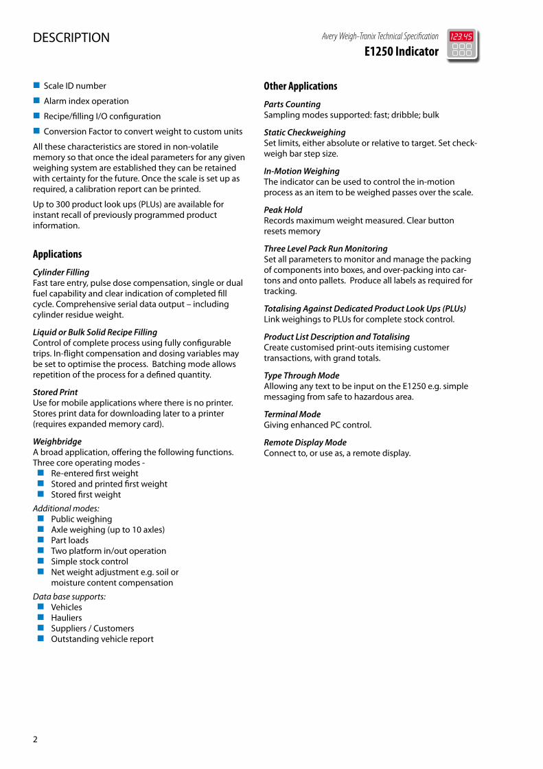
Other Applications
Parts CountingSampling modes supported: fast; dribble; bulk
Static CheckweighingSet limits, either absolute or relative to target. Set check-weigh bar step size.
In-Motion WeighingThe indicator can be used to control the in-motion process as an item to be weighed passes over the scale.
Peak HoldRecords maximum weight measured. Clear button resets memory
Three Level Pack Run MonitoringSet all parameters to monitor and manage the packing of components into boxes, and over-packing into car-tons and onto pallets. Produce all labels as required for tracking.
Totalising Against Dedicated Product Look Ups (PLUs)Link weighings to PLUs for complete stock control.
Product List Description and TotalisingCreate customised print-outs itemising customer transactions, with grand totals.
Type Through ModeAllowing any text to be input on the E1250 e.g. simple messaging from safe to hazardous area.
Terminal ModeGiving enhanced PC control.
Remote Display ModeConnect to, or use as, a remote display.
Avery Weigh-Tronix Technical Specification
E1250 Indicator
2

Avery Weigh-Tronix Technical Specification
E1250 Indicator
3
SPECIFICATION
Electrical - Display
TypeBlue back-lit dot graphic.Graphics 64 x 240 pixels.Weight display up to eight digits.
Decimal/Comma PointsConfigurable to any of seven positions
Units Displayed g, kg, lb(decimal), tonnes, custom.
AnnunciatorsBalance (Gross Zero)MotionPre-set TareSemi-Automatic TareNetlb or kg or tonnePrintFour-off Trip Output IndicatorsMinus (below net zero)Scale 1Scale 2
Membrane keyboard28 keys, addressing:Alpha entryNumeric entryFive soft Function keysDedicated Function KeysZero, Tare, Select, Print, Units, Totals, Scale, PLU, Standby, Escape, Enter, Clear, Text
Load Cell Input
Analogue InputCombined minimum load cell impedance must be greater than 22Ω.
Maximum Load Cells if 350Ω (one scale, mains powered)8.
Maximum number of 350Ω Load Cells if second scale card fitted (mains powered)12.
Load cell connectionDirect wired
Excitation supply (no load cells connected)10V DC*, up to 460mA (mains)5V DC**, up to 325mA (DC)
Nominal Excitation Voltage (350Ω load cells)
Single Load Cell Four Load Cells
Battery 4.7 V 4.1 V
AC Power 9.0V 7.0V
Safety DescriptionAbsolute Maximum Ratings
Load Cell Interface
Battery Powered
AC Mains Powered
Uo 5.277 Vdc 10.554 Vdc
Io 0.325 A 0.317 A
Po 0.428 W 0.835 W
Co 70.94 µF 2.26 µF
Lo 336 µH 353 µH
Remote SenseIt is necessary that the instrument has a reference voltage obtained from the excitation. This is provided automatically when using six wire load systems. Alternatively, the reference may be derived at the indicator.
Input Impedance 1MΩ paralleled with 2.2nF
signal6-30 mV maximum.
μV/ per Division 0.6 approved, 0.3 unapproved
Resolution Approved 10,000 (OIML)Non- Approved 60,000
Calibration
Full digital multi-point (ten point) calibration.
Theoretical calibration possible if parameters known.
Provides over load report. Stores the greatest weight ever seen since last reset together with time and date
Increment Multiplier1, 2, 5, 10, 20, 50, 100, 200, 500.
AVR (automatic variable resolution)Three stage.
Gravity CompensationSet gravity for calibration and the install on site.
Analogue to Digital Convertor
Display Update Rate1, 2, 5, 10 per second.
A to D Rate120 per second.
A to D Type Delta Sigma.
SPECIFICATIONS
* Nominal series resistance 36 OHMS, output voltage depends on load cell load.** Nominal series resistance 18 OHMs, output voltage depends on load cell load.
Filter
FIR & Dynamic FilteringSeven programmable Options
Dynamic FilterApplied after the FIR filter. Set the filter window size in divisions (0 - 99). A high value will have a large damping effect on the weight display. This significantly slows the scale response to erroneous signals.
Harmonizer™ Digital FilterThree programmable parameters:
Samples to AverageSets number of A-D conversions which will be averaged to give a weight reading.
IIR FilterSets how much damping the Harmonizer™ applies to the weight reading. Typically between 1 (low) - 8 (higher).
Threshold LevelSets the minimum weight change (in calibration units) which the Harmonizer™ will not attempt to filter out as noise.
Balance/Zero
SettingKeyboard push button.
Operation Ignore or recall limit exceeded.
Size of Balance Range Normally 2%, up to 100%.
Zero Indication Within 2% of maximum capacity.
Under Range IndicationDisplays ‘Under Range’.
Zero TrackingConfigurable
Motion DetectionConfigurable.
Range/Span
Range of Adjustment0 - 100,000 divisions.
Over Range Indication Displays ‘Over Range’.
TaresThree types of tares are available. Each is 100% subtractive. Note: Interlocks between the tare types are configurable at time of commissioning.
SPECIFICATIONS
Type A - Push-Button (Semi Auto) TarePush-button operated, semi-automatic, with selectable negative weight display. Cumulative taring is possible.
Initialisation and OperationWhen the item to tare on is applied, press the ‘Tare’ push-button.
Indication‘Net’ annunciator is illuminated.
Type B – Keyboard (Pre-set) TareKeyboard-entered tare operated with negative weight display.
Initialisation & OperationEnter pre-set tare value using the 0-9 keypad and press ‘Tare’ push button. Multiple pre-set tares are possible.
Indication‘Net’ annunciator is illuminated together with pre-set tare annunciator (PT).
Type C - Stored TareStored tare operated with negative weight display allowing 40 separate stored tares. Will be retained when power is off. Linked to any PLU.
Initialisation & OperationAutomatically activated when PLU activated, or entered direct from keyboard.
Indication‘Net’ icon is illuminated together with preset tare icon (PT).
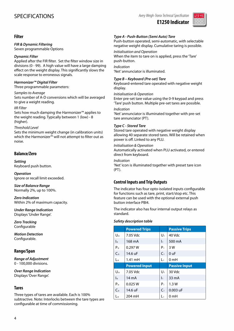
Control Inputs and Trip OutputsThe indicator has four opto-isolated inputs configurable for functions such as tare, print, start/stop etc. This feature can be used with the optional external push button interface PBI4.
The indicator also has four internal output relays as standard.
Safety description table
Powered Trips Passive Trips
Uo 7.05 Vdc U i 40 Vdc
Io 168 mA I i 500 mA
Po 0.297 W P i 3 W
Co 14.6 uF C i 0 uF
Lo 1.41 mH L i 0 mH
Powered Input Passive Input
Uo 7.05 Vdc U i 30 Vdc
Io 14 mA I i 33 mA
Po 0.025 W P i 1.3 W
Co 14.6 uF C i 0.003 uF
Lo 204 mH L i 0 mH
Avery Weigh-Tronix Technical Specification
E1250 Indicator
4
Avery Weigh-Tronix Technical Specification
E1250 Indicator
5
Two modes have independent control of the outputs, Alarm and Recipe. Alarm mode operates continuously.
Recipe mode is dependant on the Recipe / Filling application being configured and in operation.
Alarm ModeAlarm mode has 10 independent configurable indexes and cannot be turned off. Each index can be programmed to operate any or all outputs based on a given target:- None - index inactive- Target Weight- Status of indicator, e.g. weight steady,
check-weigh accept- Input (single or specific pattern)- Output (single or specific pattern)- Time
Recipe / Filling ModeRecipe / Filling mode has 50 configurable sequential steps, and is active only in Recipe / Filling mode. Each recipe (maximum 100) can be configured independently to the others. Each index can be programmed to operate any or all outputs based on a given target:- None – index inactive- Target Weight (includes tolerance,
compensation and dosing parameters)- Status of indicator, e.g. weight steady, check-weigh accept- Input (single or specific pattern)- Output (single or specific pattern)- Time
Other variables that can be configured in Recipe / Filling mode are:- Outputs at start of step- Outputs at end of step- Target action (e.g. print)- PLU to accumulate totals data
All configuration information is retained when power is removed.
Product Look Ups (PLUs) & Totals
Information Stored per PLU Sub-totals and grand totals.Application specific info stored per PLU.
User Definable Text Fields per PLU3, each 21 characters.
When a PLU is recalled, the indicator automatically loads the application programme associated with the PLU. All PLU information can be printed.
Real Time ClockThe E1250 is fitted with a battery backed real time clock which allows the user to display and print the time and date.
Communications
Serial Interface
Two bi-directional asynchronous fibre optic serial interfaces, for connection to optional fibre optic to RS232 or 422 transceivers mounted remotely in the safe area.
Mains Electrical Power Input (via separate power supply module)
Voltage 100 VAC - 240 VAC nominal, 50/60 Hz.
ToleranceVoltage -15 to +10%.Frequency ±10%.Power Consumption 25 VA maximum when used withfull configuration of load cells.
Cable Length 2 m.
Earthing (grounding):System must be connected to intrinsically safe earth if barriers are used in the system or, a standard electrical safety earth, if not
Protection:It is recommended that the power supply is connected to a clean AC mains supply.
Cable SpecificationThe power input cable to the AC mains power supplies located in the hazardous area conform to the following specification:
Three core fleible armoured SY type 30/0.25 1.5 mm2, 16A rated. Overall diameter 10.6 mm, PVC transparent sheath.
This power supply does not have a junction box. The cable may be protected by conduit and is connected to the power supply by a threaded boss arangement.
Battery Power6V, 10AHr battery pack, to be used in conjunction with Avery Weigh-Tronix safe area battery charger.
SPECIFICATIONS
Environment
Resistance to Dirt and MoistureProtected to IP67, in stainless steel enclosure.
Electrical DisturbanceImmune to electrical disturbance, including RFI as detailed in EN 45501:1992
Operating Temperature (approved)-10° C to + 40° C.
Service Temperature -10° C to + 50° C.
Storage Temperature-40° C to +70° C.
Finish
Brushed and pickled 304 stainless steel enclosure.
Mounting Options
The indicator will desk, wall or pole mount with the bracket as supplied. For close wall mounting, a stainless steel mounting kit is available as an option. Note this kit will prevent changing the angle of the front panel.
Performance
ResolutionUp to 60,000 divisions (unapproved).
Repeatability± 0.01% of full scale.
Warm Up TimeThe indicator meets accuracy specifications immediately self-test routines are complete following power up.
Approvals
WeighingApproved in Europe to the Non-Automatic Weighing Instruments (NAWI) Directive 93/68/EEC. Tested to EN45501: 1994 and OIML R76-1 accuracy class III. The type approval certificate numbers being:EU: UK2758 OIML: R76/1992-GB1-05.01
Hazardous AreaApproved in Europe to the ATEX directive 94/9/EC for use in hazardous areas to CENELEC standards. Suitable for all surface gas groups, Zones 1 and 2 & dust Zones 21 and 22. Temperature Classes T1 to T4
II 2 GD T135°C, t. amb. 50°CIndicator. Ex ib IIC T4, t. amb. 50°C
SPECIFICATIONS
Power supply options1. Mains power supply. Ex mb [ib] IIC T4, t. amb. 50°C2. Battery pack. Ex m ib IIC T4, t. amb. 50°C
Hazardous area optionsATEX junction boxesPiezo-pneumatic solenoid valvePBI4Remote displays
Base indicator part number, no power supplyE1250EX0400000
Factory Options
Power supply options
1. Power supply, 100 to 240VAC, powers one indicatorE1150EX0000600
2. Battery Pack, 6V, 10AHr, powers one indicatorE1150EX0000800
3. Safe area battery charger for 6V, 10AHr battery packMust be used in safe areaE1150EX0000900
Indicator options
11. Second scale input card (Analogue card). Provides second scale input capability E1150EX0000100
12. Expanded memory card, 1.5 MB Securely stores up to 72,000 transactions, with details of scale ID, gross/tare/net weights, time, date and consecutive number.E1150EX0000300
Hazardous area options
21. ATEX junction box (JBIT) for 4 load cells (cornering)E1150EX0003000
22. ATEX junction box (JBIT) for 2 load cells complete with lightning protection (cornering)E1150EX0002800
23. ATEX junction box (JBIT) for 4 load cells complete with lightning protection (cornering)E1150EX0002900
24. Stainless steel wall mount bracket for indicator enclosure E11050A00000000
25. Stainless steel 300mm mounting pole for indicator enclosure, including top plateE11100U00000000
Avery Weigh-Tronix Technical Specification
E1250 Indicator
6
Avery Weigh-Tronix Technical Specification
E1250 Indicator
7
26. Stainless steel 1000mm mounting pole for indicator enclosure, including top plateE11100V00000000
27. Indicator to platform lead, 5m (not factory fitted)E11100R00000000
28. Indicator to platform lead, 10m (not factory fitted)E11100T00000000
29. Intrinsically safe piezo-pneumatic 3/2 solenoid valve1/8” BSP, for interface directly with indicator via relay output. Needs oil free, 5 micron filtered, air supplyY8097B00000000
30. Fibre optic cable, plastic, 100mL1170J0000KA00
31. PBI44 x push buttons, indicator powered, for connection to indicator control inputs, includes 10m of cable. Can be used to zero, tare, start/stop process etc. E1150EX0003100
32. Remote display, 3.5 digit, 4/20mA input via galvanic isolator from safe area (not supplied)E1150EX0003200
33. Remote display, 4.5 digit, 4/20mA input via galvanic isolator from safe area (not supplied)E1150EX0003300
Safe area options
50. Fibre optic serial to 4/20mA converterConsisting of a fibre optic transceiver and 4/20mA module housed in a wall mounted safe area module. Requires one indicator fibre optic serial channel. Accuracy 0.1% of full scale, 12 bit. Analogue output temperature coefficient 20ppm/°C typical. Current output load 500Ω maximum (current is source only not sink) Voltage output load 5KΩ maximum, UK plugL1170H0000HC00
51. As 50, USA plugL1170H0000HC00QB
52. As 50, Australian plugL1170H0000HC00EA
53. As 50, EU plugL1170H0000HC00EU
54. As 50, RSA plugL1170H0000HC00FA
55. Safe area interface lead for Epson form printerL1170L000000JA
56. Safe area interface lead for Epson TM-295 printerL1170L000000FA
57. Transceiver, fibre optic serial input to RS232 or RS422 serial output. Transceiver fitted with 25 pin D plug (female), 230VAC, UK plugL1170J000000DB
58. As 58, 110VAC, USA plugL1170J000000DBQB
59. As 58, 230VAC, EU plugL1170J000000DBEU
60. As 58, 230VAC, RSA plugL1170J000000DBFA
61. Transceiver, fibre optic to RS232/RS422 wall mount kitL1170J000000FB
62. Indicator safe area service tool. Allows e-tools to be used to configure the indicator in a safe area71015-394
OPTIONS
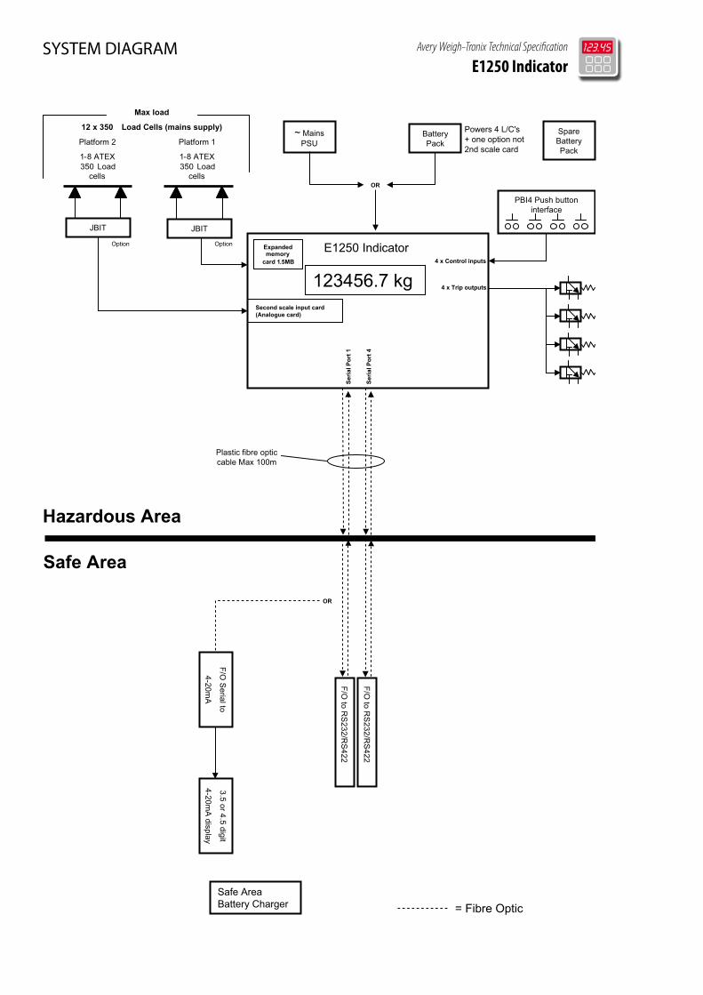
SYSTEM DIAGRAM Avery Weigh-Tronix Technical Specification
E1250 Indicator
= Fibre Optic
Avery Weigh-Tronix Technical Specification
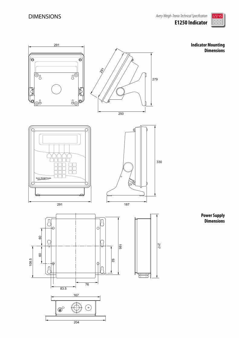
E1250 IndicatorDIMENSIONS
279
250
291
291
291 187
330
230170
175130
15
217
195
167
204
83.576
92
6060
108.
5
Indicator Mounting Dimensions
Power Supply Dimensions
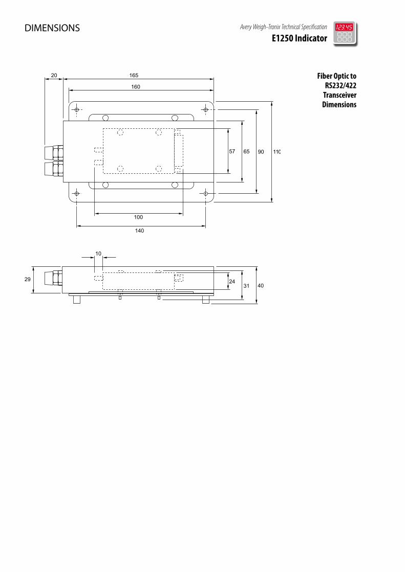
DIMENSIONS Avery Weigh-Tronix Technical Specification
E1250 Indicator
Fiber Optic to RS232/422
Transceiver Dimensions
57
2431
100
10
29
165
65
20
90
140
160
110
40
Avery Weigh-Tronix Technical Specification
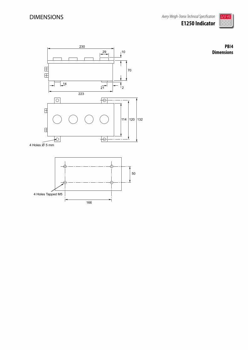
E1250 IndicatorDIMENSIONS
166
50
4 Holes Tapped M5
4 Holes 5 mm
223
1421
10
70
2
114 120 132
29230 PBI4
Dimensions
© Avery Weigh-Tronix group of companies 2009. All rights reserved. Avery Weigh-Tronix is a registered trade mark of the Avery Weigh-Tronix group of companies. This publication is issued to provide outline information only which, unless agreed by an Avery Weigh-Tronix group company in writing, may not be regarded as a representation relating to the products or services concerned. This publication was correct at the time of going to print however, Avery Weigh-Tronix reserves the right to alter without notice the specification, design, price or conditions of supply of any product or service at any time.
Please call us or visit www.averyweigh-tronix.com for your nearest Avery Weigh-Tronix distributor
avery weigh-tronix - uKFoundry Lane, Smethwick, West Midlands B66 2LP [email protected]: +44 (0) 8453 66 77 88Fax: +44 (0) 121 224 8183
avery weigh-tronix - usa1000 Armstrong Drive, Fairmont, MN 56031-1439 [email protected]: (800) 533-0456 Phone: (507) 238-4461
10/09 E1250_Spec_500188.indd (C&D)AWT35-500188
Avery Weigh-Tronix Technical Specification
E1250 Indicator