LED Indicator and Display Products
82
LED Indicator and Display Products Selection Guide Smart Displays Light Bars and Bar Graph Arrays Standard and High Brightness Through-hole Lamps Surface Mount ChipLEDs Auto Focus Auxiliary Flash LED Surface Mount PLCC LEDs Subminiature Lamps Seven-Segment Displays Envisium Power PLCC-4 Surface Mount LEDs
-
Upload
khangminh22 -
Category
Documents
-
view
0 -
download
0
Transcript of LED Indicator and Display Products

LED Indicator and Display Products
Selection GuideSmart Displays
Light Bars and Bar Graph Arrays
Standard and High Brightness
Through-hole Lamps
Surface Mount ChipLEDs
Auto Focus Auxiliary Flash LED
Surface Mount PLCC LEDs
Subminiature Lamps
Seven-Segment Displays
Envisium Power PLCC-4 Surface Mount LEDs

2 Smart Displays
9 Light Bars and Bar Graph Arrays
13 Standard and High Brightness Through-hole Lamps
32 Surface Mount ChipLEDs
39 Auto Focus Auxiliary Flash LED
41 Surface Mount PLCC LEDs
48 Subminiature Lamps
52 Seven-Segment Displays
76 Envisium Power PLCC-4 Surface Mount LEDs

1
Avago Technologies is one of the largest producers of visible light-emitting diodes in the world.Applications ranging from automotive to consumer electronics and appliances and industrial all call for the effi ciency and reliability of LED lighting. Avago Technologies’ surface-mount, through-hole and display products are the LEDs of choice for many of these applications.
Avago Technologies employs the latest in material and process technology to produce superior LED chips. Avago Technologies’ acclaimed AlInGaP (aluminum indium gallium phosphide) LED material off ers high brightness, stable light output over many thousands of hours and excellent mean-time-before-failure (MTBF), which means that your product looks brilliant now and for a long, long time. Dazzling blue and green colors are available with InGaN (indium gallium nitride) material, and very cost-eff ective GaP (gallium phosphide)-based technologies are perfect for low to moderate light output requirements. Avago Technologies’ LEDs combine vivid colors with an array of package options suited for almost any application—and the LEDs you need are available today.
Avago Technologies off ers an unparalleled combination of manufacturing strength and global technical support. Our facilities specializing in high-volume, low-cost manufacturing produce millions of LEDs every year, which assures that the LED products you need are available, in volume, when you need them.
For virtually all established and emerging applications, Avago Technologies has the right product to meet your design requirements.
We deliver LEDs in an array of colors and packages so our customers can deliver innovative, new products.
Application Standard Through-hole Lamps
High-brightness Through-hole Lamps
Surface Mount ChipLEDs
Auto Focus Auxiliary Flash LED
Surface Mount PLCC LEDs
Envisium Power PLCC-4
Submin-iature Lamps
Seven Segment Displays
Light Bars & Bar Graph Arrays
Smart Displays
Electronic Signs & Signals • • • • •
Consumer Electronics • • • • • • • • •
Automotive Interior • • • • •
Automotive Exterior • •
Mobile Appliances • •
Industrial Equipment • • • • • • • •
Computer & Offi ce Equipment • • • • • • • •
Home Appliances • • • • • • • •
Medical Equipment • • • • • • • •
Avionics •

2
Smart Displays
Description
Avago Technologies off ers high quality Smart Displays to meet a wide range of applications and requirements. The smart displays are available in both serial and parallel interface and have an ASIC driver that greatly simplifi es design eff orts. The smart displays are LED technology-based and are extremely reliable with a long life expectancy. They are resistant to extreme weather conditions, and to mechanical vibration and shock, making them suitable for industrial applications where maintenance resources are scarce. They are also suitable for the consumer market where the need for aesthetics and product diff erentiation provides a competitive advantage to our customers’ end products. Avago Technologies’ smart display products are positioned to support high volume and cost-eff ective solutions. Supporting custom displays is a possibility.
Features and Benefi ts
• Robust design for high reliability, longer life and hot and cold temperature operating capability
• Ideally suited for outdoor, industrial and automotive applications
• Alphanumeric characters and custom icons for messaging
• Useful for conveying operating modes, status, warning and error codes
• Ability to fl ash or blink • Catch user’s attention• ASIC LED driver • Simplifi ed design interfacing reduces
design cycle time• Emissive display with brightness control • Ability to modify brightness for
subdued light environment and total darkness
• Aesthetically pleasing • Distinctive display allows product
diff erentiation
Typical Applications
• Industrial Equipment • Industrial ovens, reliability test
equipment, analytical instruments, process control equipment, test and measuring instruments, temperature controllers, programmable logic controllers, security systems
• Networking • Telecommunication equipment,
answering machines, telephones, base stations, PBX modems, network cards
• Outdoor Signs • Petrol pump meters• Consumer • Audio/video equipment, audio mixers,
set top boxes, amplifi ers, musical instruments, gaming machines, currency/coin counters, security systems
• Consumer “White Goods” • Displays for washing machine digital
panels, cookers, freezers and dishwashers
• Medical Equipment • Hospital monitoring systems• Transportation • Displays, radar detectors, avionics
displays• Computers and Peripherals • CPU speed indicator, printer front
panels, fax machines, copy machines, power supply equipment, cash registers
3
Smar
t Disp
lays
Part Number Character Color Interface Character Height (mm)
Intensity, Typ. (µcd)
Supply, Typ. (mA)
HCMS-2901 4 Yellow Serial 3.7 64 132HCMS-2902 4 Red Serial 3.7 64 132HCMS-2903 4 Green Serial 3.7 114 132HCMS-2904 4 Orange Serial 3.7 64 132HCMS-2905 4 AlGaAs Red Serial 3.7 230 145HCMS-2961 4 Yellow Serial 4.6 64 132HCMS-2962 4 Red Serial 4.6 64 132HCMS-2963 4 Green Serial 4.6 114 132HCMS-2964 4 Orange Serial 4.6 64 132HCMS-2965 4 AlGaAs Red Serial 4.6 230 145HCMS-2911 8 Yellow Serial 3.7 64 264HCMS-2912 8 Red Serial 3.7 64 264HCMS-2913 8 Green Serial 3.7 114 264HCMS-2914 8 Orange Serial 3.7 64 264HCMS-2915 8 AlGaAs Red Serial 3.7 230 290HCMS-2971 8 Yellow Serial 4.6 64 264HCMS-2972 8 Red Serial 4.6 64 264HCMS-2973 8 Green Serial 4.6 114 264HCMS-2974 8 Orange Serial 4.6 64 264HCMS-2975 8 AlGaAs Red Serial 4.6 230 290HCMS-2921 16 Yellow Serial 3.7 64 528HCMS-2922 16 Red Serial 3.7 64 528HCMS-2923 16 Green Serial 3.7 114 528HCMS-2924 16 Orange Serial 3.7 64 528HCMS-2925 16 AlGaAs Red Serial 3.7 230 580HCMS-3906 4 Red Serial 3.7 1150 132HCMS-3902 4 Red Serial 3.7 64 132HCMS-3966 4 Red Serial 4.6 1150 132HCMS-3916 8 Red Serial 3.7 1150 264HCMS-3976 8 Red Serial 4.6 1150 264HCMS-3912 8 Red Serial 3.7 64 264HCMS-3962 4 Red Serial 4.6 64 132HCMS-3972 8 Red Serial 4.6 64 264HCMS-3907 4 Green Serial 3.7 500 132HCMS-3917 8 Green Serial 3.7 500 264HCMS-3967 4 Green Serial 4.6 500 132HCMS-3977 8 Green Serial 4.6 500 264HCMS-3904 4 Orange Serial 3.7 64 132HCMS-3914 8 Orange Serial 3.7 64 264HCMS-3964 4 Orange Serial 4.6 64 132HCMS-3974 8 Orange Serial 4.6 64 264
Plastic Package, Serial Interface, 5 x 7 Dot Matrix Display with Custom Font Programmable
Notes:
Typical values at TA = 25°C.
Luminous intensity for one pixel at VLED = 5.0 V, 50% peak pixel current, 100% pulse width.
Supply current at VLED = 5.0V, 100% peak pixel current, 100% pulse width, 20 pixels per digit at all digit locations.

4
Notes:
Typical values at VDD = 5.0V, TA = 25°C.
Luminous intensity at 100% full brightness, character average with “#” (20 pixels) displayed.
Supply current at 100% brightness, with all character locations displaying “#” (20 pixels).
Part Number Character Color Interface Character Height (mm)
Intensity, Typ. (µcd)
Supply, Typ. (mA)
HDLY-1414 4 Yellow Parallel 3.6 3.7 110
HDLO-1414 4 Red Parallel 3.6 3.5 110
HDLG-1414 4 Green Parallel 3.6 5.6 110
HDLA-1414 4 Orange Parallel 3.6 3.5 110
HDLU-1414 4 AlGaAs Red Parallel 3.6 3.1 34
HDLS-1414 4 AlGaAs Red Parallel 3.6 12.7 125
HDLY-2416 4 Yellow Parallel 5.1 3.7 110
HDLO-2416 4 Red Parallel 5.1 3.5 110
HDLG-2416 4 Green Parallel 5.1 5.6 110
HDLA-2416 4 Orange Parallel 5.1 3.5 110
HDLU-2416 4 AlGaAs Red Parallel 5.1 3.1 34
HDLS-2416 4 AlGaAs Red Parallel 5.1 12.7 125
HDLY-3416 4 Yellow Parallel 6.9 3.7 110
HDLO-3416 4 Red Parallel 6.9 3.5 110
HDLG-3416 4 Green Parallel 6.9 5.6 110
HDLA-3416 4 Orange Parallel 6.9 3.5 110
Plastic Package, Serial Interface, 5 x 7 Dot Matrix Display with Custom Font Programmable
Part Number Character Color Interface Character Height (mm)
Intensity, Typ. (µcd)
Supply, Typ. (mA)
HDSP-2530 8 Orange Parallel 4.6 7.5 300
HDSP-2531 8 Yellow Parallel 4.6 7.5 300
HDSP-2532 8 Red Parallel 4.6 7.5 300
HDSP-2533 8 Green Parallel 4.6 7.5 300
HDSP-2534 8 AlGaAs Red Parallel 4.6 15 330
HDSP-2110 8 Orange Parallel 4.8 7.5 300
HDSP-2111 8 Yellow Parallel 4.8 7.5 300
HDSP-2112 8 Red Parallel 4.8 7.5 300
HDSP-2113 8 Green Parallel 4.8 7.5 300
HDSP-2107 8 AlGaAs Red Parallel 4.8 15 330
HDSP-2500 8 Orange Parallel 7.0 7.5 300
HDSP-2501 8 Yellow Parallel 7.0 7.5 300
HDSP-2502 8 Red Parallel 7.0 7.5 300
HDSP-2503 8 Green Parallel 7.0 7.5 300
HDSP-2504 8 AlGaAs Red Parallel 7.0 1.5 330
Plastic Package, Parallel Interface, 8 Character, 5 x 7 Dot Matrix Display with 128 Character ASCII Decoder

5
Smar
t Disp
lays
Notes:
Typical values at VDD = 5.0V, TA = 25°C.
Luminous intensity per LED (Digit Average).
Supply current with “5” or “B” character displayed.
Notes:
Typical values at VDD = 5.0V, TA = 25°C.
Luminous intensity at 100% full brightness, character average with “#” (20 pixels) displayed.
Supply current at 100% brightness, with all character locations displaying “#” (20 pixels).
Notes:
Typical values at VDD = 5.0V, TA = 25°C.
Luminous intensity at 100% full brightness, character average with “#” (20 pixels) displayed.
Supply current at 100% brightness, with all character locations displaying “#” (20 pixels).
Part Number Character Color Interface Character Height (mm)
Intensity, Typ. (µcd)
Supply, Typ. (mA)
HDSP-2131 8 Yellow Parallel 4.8 7.5 300
HDSP-2132 8 Red Parallel 4.8 7.5 300
HDSP-2133 8 Green Parallel 4.8 7.5 300
HDSP-2179 8 Orange Parallel 4.8 7.5 300
Glass/Ceramic Package, Parallel Interface, 8 Character, 5 x 7 Dot Matrix with 128 Character ASCII Decoder
Part Number Character Color Interface Character Height (mm)
Intensity, Typ. (µcd)
Supply, Typ. (mA)
HPDL-1414 4 Red Parallel 2.9 1.0 70
Plastic Package, Parallel Interface, 16 Segment Alphanumeric Display, 4 Character with 64 Character ASCII Decoder
Part Number Description/Decimal Point
Color Operation Temperature (°C )
Character Height (mm)
Luminous Intensity Typ. (µcd)
Supply Current Typ. (mA)
HDSP-0760 Numeric, RHDP HER -55 to 85 7.4 140 78
HDSP-0761 Numeric, LHDP HER -55 to 85 7.4 140 78
HDSP-0762 Hexadecimal HER -55 to 85 7.4 140 78
HDSP-0770 Numeric, RHDP HER -55 to 85 7.4 620 120
HDSP-0771 Numeric, LHDP HER -55 to 85 7.4 620 120
HDSP-0772 Hexadecimal HER -55 to 85 7.4 620 120
HDSP-0860 Numeric, RHDP Yellow -55 to 85 7.4 490 120
HDSP-0861 Numeric, LHDP Yellow -55 to 85 7.4 490 120
HDSP-0862 Hexadecimal Yellow -55 to 85 7.4 490 120
HDSP-0960 Numeric, RHDP Green -55 to 85 7.4 1100 120
HDSP-0961 Numeric, LHDP Green -55 to 85 7.4 1100 120
HDSP-0962 Hexadecimal Green -55 to 85 7.4 1100 120
Glass/Ceramic Package, 4 x 7 Hexadecimal Display with Built-in BCD Decoder/Driver

6
Notes:
Typical values at VDD = 5.0V, TA = 25°C.
Luminous intensity per LED (Digit Average).
Part Number Description/Decimal Point
Color Operation Temperature (°C )
Character Height (mm)
Luminous Intensity Typ. (µcd)
Supply Current Typ. (mA)
HDSP-0763 Overange ± 1 HER -55 to 85 7.4 140 11.2
HDSP-0863 Overange ± 1 Yellow -55 to 85 7.4 490 32
HDSP-0963 Overange ± 1 Green -55 to 85 7.4 1100 32
Glass/Ceramic Package Over Range ± with Built-in BCD Decoder/Driver

2.11 (0.083) TYP.PIN # 1 IDENTIFIER
4321
17.78 (0.700) MAX.
3.71 (0.146) TYP.
4.45 (0.175)TYP.
2.22 (0.087) SYM.
10.16 (0.400) MAX.
1
12
35.56 (1.400) MAX.
76543210
PIN # 1 IDENTIFIER
2.22 (0.087) SYM.
10.16 (0.400) MAX.
2.11 (0.083) TYP.
4.45 (0.175)TYP.
3.71 (0.146) TYP.
3
26
3210
PIN # 1 IDENTIFIER
2.67(0.105)SYM.
2.54 (0.100) TYP.
11.43 (0.450) MAX.
5.36 (0.211) TYP.
4.57 (0.180)TYP.
21.46 (0.845) MAX.
87654321
PIN # 1 IDENTIFIER
42.93 (1.690) MAX.
2.67 (0.105) SYM.
5.36 (0.211) TYP.
11.43 (0.450) MAX.
2.54 (0.100) TYP.
4.57 (0.180)TYP.
3
26
76543210
15141312111098
PIN # 1 IDENTIFIER
35.56 (1.400) MAX.
2.22 (0.088) SYM.
4.45 (0.175) MAX.
19.81 (0.780) MAX.
2.11 (0.083) TYP.
3.71 (0.146)
TYP.
4.83 (0.190)
3A
3B
26B
26A
9.65 (0.380)
Row B
Row A
7
Smar
t Disp
lays
LED Dot Matrix Smart Displays Package Dimension Drawings
HCMS-290x/HCMS-390x HCMS-291x/HCMS-391x
HCMS-296x/HCMS-396x HCMS-297x/HCMS-397x
DIMENSIONS ARE IN MILLIMETERS (INCHES)
HCMS-292x

8
HDSP-250x
HPDL-1414
HDLx-2416
DIMENSIONS ARE IN MILLIMETERS (INCHES)
HDSP-213x, -2179
HDLx-1414 HDLx-3416
HDSP-253x HDSP-2107, -211x
PIN # 1 IDENTIFIER
42.93 (1.690) MAX.
2.68 (0.105) SYM.
5.36 (0.211) TYP.
11.43(0.450)MAX.
2.54 (0.100) TYP.
4.57 (0.180)
TYP.
2.290.090
SYM.
0 1 2 3 4 5 6 70
PIN # 1 IDENTIFIER
42.59 (1.677)
5.33 (0.210) TYP.
19.58(0.771)
2.69 (0.106)
4.81 (0.189)
1 2 3 4 5 6 7
1
28
9.8(0.386)
2.64 (0.104) SYM.
PIN DESIGNATION
0
PIN # 1 IDENTIFIER
70.87 (2.790)
8.84 (0.348) TYP.
19.41(0.764)
5.08 (0.200) TYP.
6.96 (0.274)
1 2 3 4 5 6 71
28
9.70(0.382)
PIN DESIGNATION
TYP.
4.51 (0.178)
5.08(0.200)
20.07(0.790)
25.15(0.990)
3.43(0.135)
6.35(0.250)
3.05(0.120) TYP.
PIN 1 IDENTIFIER
10.03(0.395)
2.85(0.112)
20.10(0.790)
17.50(0.690)
4.45(0.175)
TYP.
23 1 0 REF.
PIN 1 IDENTIFIER
42.72(1.68)
4.83(0.190)
2.85(0.112)
9.91(0.39)
4.96(0.195)
5.33(0.210)
TYP.
2.67 (0.105)
TYP. PIN 17
17.66(0.695)
4.45(0.175)
20.12(0.792)
9.14(0.360)
PIN 1 IDENTIFIER
0.39(0.015)
TYP.(2X)
TYP. 32.77(1.290)
8.26(0.325)
10.03(0.395)
20.07(0.790)
6.86(0.270)
4.45(0.175)PIN 1 IDENTIFIER

9
Light
Bars
and G
raph
Arra
ys
Light Bars and Bar Graph ArraysDescription — Light Bars
Light Bars are Avago Technologies’ innovative solution to fi xed message annunciaton. They are used as annunciators that serve three customer functions: status indication, backlighting fi xed messages and analog level indications (arrays). The Light Bars provide exceptional brightness at very low drive current for those applications where portability and battery backup are vital. These rectangular light sources are confi gured in single-in-line and dual-in-line packages that contain either single or segmented light emitting areas. They are also X-Y stackable.
Description — 10-Element Bar Graph Arrays
Avago Technologies’ 10-Element Bar Graph Arrays serve a market need for analog level indication. LED reliability, light emitting viewability make them suitable in place of mechanical meters. They are designed to display information in easily recognizable bar graph form. The packages are end stackable and are therefore capable of displaying long strings of information. The bar graph arrays are precision matched for both intensity and wavelength, saving you the time and trouble matching individual parts. The prealigned bar graph elements locked in a single package eliminates the task of matching and aligning individual LEDs during manufacturing, along with the risk of visually substandard front panels resulting from misaligned indicators. Each device off ers easy-to-handle packages that are compatible with standard DIP sockets.
Features & Benefi ts
• Large, Bright, Uniform Light Emitting Surface
• Yellow and Green categorized for Dominant Wavelength
• Low heat dissipation• Choices of colors — AlGaAs, HER,
Green, Yellow• Various package sizes are X-Y
stackable• Industry standard SIP and DIP
packages
Features & Benefi ts
• Exclusive package interlock • Facilitate end stacking
alignment• Large segment size • Wide viewing angle• Available in AlGaAs, Her, green,
yellow and multicolor • Wide variety of
applications• Categorized and packaged for
luminous intensity • Greater uniformity of
light output• Matched LEDs for Uniform
Appearance
Typical Applications
• Business Machines • Point of Sale Bar Code
Scanner • Electronic Typewriters • Fax machines • Electronic Scales • Postal Meters• Instrumentation • Process Control System • Medical Equipment • Machine Control
Systems • Meters and Status
Indicators
Typical Application
• Instrumentation • Meters • Channel Indicators • Status Indicators• Process Control • Level Indicators• Appliances • Status of Indication • Mode of operation• Transportation • Tachometers • Fuel Gauges
• Telecommunications • PBX Systems • Modems • Central Switching
Systems • Diagnostic Equipment • Short Wave Radios• Transportation • Automotive Dashboards • Truck and Bus Controls • Airport Passenger Metal
Detectors • Ticket Vending
Machines• Consumer • Appliance Front Panel • Hi-Fi/Stereo Equipment • Alarm System
• Consumer Products • VU Meters (Stereos) • Radio Channel Scanners • Burglar Alarms

10
Shape Size/# Light Emitting Part Number Color Chip (nm) Typ.
Vf (V) Typ.
Vf (V) at If = mA
Iv at If = mA
Iv Min. (mcd)
Iv Typ. (mcd)
2 IntensityBin Selection
0.4SIP 0.35” x 0.15” 1 area HLCP-A100 AlGaAs Red 637 1.8 20 3 3 7.5 B, C
0.4SIP 0.35” x 0.15” 1 area HLMP-2300 GaP Red 626 2 20 20 6 23 E, F
0.4SIP 0.35” x 0.15” 1 area HLMP-2400 GaP Yellow 585 2.1 20 20 6 20 E, F
0.4SIP 0.35” x 0.15” 1 area HLMP-2500 GaP Green 572 2.2 20 20 5 25 F, G
0.8SIP 0.75” x 0.15” 1 area HLCP-B100 AlGaAs Red 637 1.8 20 3 6 15 B, C
0.8SIP 0.75” x 0.15” 1 area HLMP-2350 GaP Red 626 2 20 20 13 45 E, F
0.8SIP 0.75” x 0.15” 1 area HLMP-2450 GaP Yellow 585 2.1 20 20 13 38 E, F
0.8SIP 0.75” x 0.15” 1 area HLMP-2550 GaP Green 572 2.2 20 20 11 50 F, G
0.4DIP 0.35” x 0.35” 1 area HLCP-C100 AlGaAs Red 637 1.8 20 3 6 15 –
0.4DIP 0.35” x 0.35” 1 area HLMP-2655 GaP Red 626 2 20 20 13 45 E, F
0.4DIP 0.35” x 0.35” 1 area HLMP-2755 GaP Yellow 585 2.1 20 20 13 38 E, F
0.4DIP 0.35” x 0.35” 1 area HLMP-2855 GaP Green 572 2.2 20 20 11 50 F, G
0.4DIP 0.35” x 0.15” 2 areas HLCP-D100 AlGaAs Red 637 1.8 20 3 3 7.5 B, C
0.4DIP 0.35” x 0.15” 2 areas HLMP-2600 GaP Red 626 2 20 20 6 23 E, F
0.4DIP 0.35” x 0.15” 2 areas HLMP-2700 GaP Yellow 585 2.1 20 20 6 20 E, F
0.4DIP 0.35” x 0.15” 2 areas HLMP-2800 GaP Green 572 2.1 20 20 5 25 –
0.8DIP 0.35” x 0.15” 4 areas HLCP-E100 AlGaAs Red 637 1.8 20 3 3 7.5 B, C
0.8DIP 0.35” x 0.15” 4 areas HLMP-2620 GaP Red 626 2 20 20 6 23 E, F
0.8DIP 0.35” x 0.15” 4 areas HLMP-2720 GaP Yellow 585 2.1 20 20 6 20 E, F
0.8DIP 0.35” x 0.15” 4 areas HLMP-2820 GaP Green 572 2.2 20 20 5 25 F, G
0.8DIP 0.15” x 0.75” 2 areas HLCP-F100 AlGaAs Red 637 1.8 20 3 6 15 –
0.8DIP 0.15” x 0.75” 2 areas HLMP-2635 GaP Red 626 2 20 20 13 45 –
0.8DIP 0.15” x 0.75” 2 areas HLMP-2735 GaP Yellow 585 2.1 20 20 13 38 –
0.8DIP 0.15” x 0.75” 2 areas HLMP-2835 GaP Green 572 2.2 20 20 11 50 –
0.8DIP 0.35” x 0.35” 2 areas HLCP-G100 AlGaAs Red 637 1.8 20 3 6 15 –
0.8DIP 0.35” x 0.35” 2 areas HLMP-2670 GaP Red 626 2 20 20 13 45 –
0.8DIP 0.35” x 0.35” 2 areas HLMP-2770 GaP Yellow 585 2.1 20 20 13 38 –
0.8DIP 0.35” x 0.35” 2 areas HLMP-2870 GaP Green 572 2.2 20 20 11 50 F, G
0.8DIP 0.35” x 0.75” 1 areas HLCP-H100 AlGaAs Red 637 1.8 20 3 12 30 B, C
0.8DIP 0.35” x 0.75” 1 areas HLMP-2685 GaP Red 626 2 20 20 22 80 –
0.8DIP 0.35” x 0.75” 1 areas HLMP-2785 GaP Yellow 585 2.1 20 20 26 70 E, F
0.8DIP 0.35” x 0.75” 1 areas HLMP-2885 GaP Green 572 2.2 20 20 22 100 F, G
Light Bars

11
Light
Bars
and G
raph
Arra
ys
Shape Size/# Light Emitting Part Number Color Chip (nm) Typ.
Vf (V) Typ.
Vf (V) at If = mA
Iv at If = mA
Iv Min. (mcd)
Iv Typ. (mcd)
2 IntensityBin Selection
0.4DIP 0.35” x 0.35” 1 area HLMP-2950 GaP RedGaP Yellow
626 2 20 20 13 45 –585 2.1 20 20 13 38 –
0.4DIP 0.35” x 0.35” 1 area HLMP-2965 GaP RedGaP Green
626 2 20 20 19 45 –572 2.2 20 20 25 50 –
Bicolor Light Bars
10 Element HLCP-J100 AlGaAs Red 637 1.6 1 1 600 1000 –HDSP-4830 GaP Red 626 2.1 20 10 900 3500 G, HHDSP-4840 GaP Yellow 585 2.2 20 10 600 1900 F, GHDSP-4850 GaP Green 572 2.1 10 10 600 1900 H, I
Multicolor LA HDSP-4832 GaP Red 626 2.1 20 10 600 3500 –GaP Yellow 585 2.2 20 10 600 1900 –GaP Green 572 2.1 10 10 600 1900 –
HDSP-4836 GaP Red 626 2.1 20 10 600 3500 –GaP Yellow 585 2.2 20 10 600 1900 –GaP Green 572 2.1 10 10 600 1900 –GaP Yellow 585 2.2 20 10 600 1900 –GaP Red 626 2.1 20 10 600 3500 –
Bar Graph Arrays
Bin ID Customer Iv in mcdMin. Max.
AlGaAs Red HLCP-A100 / D100 / E100GaP Red HLMP-2300 / 2600 / 2620B 4.5 8.2C 6.8 12.1D 10.1 18.5E 15.3 27.8F 22.8 45.5AlGaAs Red HLCP-B100 / C100 / F100 / G100GaP Red HLMP-2350 / 2635 / 2655 / 2670B 9.0 16.0C 13.1 24.0D 19.7 36.1E 29.6 54.2F 44.9 88.8AlGaAs Red HLCP-H100GaP Red HLMP-2685B 18.0 27.1C 22.0 40.8D 33.3 61.1E 50.0 91.8F 75.1 150.0
Luminous Intensity Categories
Bin ID Customer Iv in mcdMin. Max.
GaP Yellow HLMP-2400 / 2700 / 2720 E 13.8 25.3F 20.7 41.4HLMP-2450 / 2735 / 2755 / 2770 E 27.0 50.0F 40.5 81.0HLMP-2785 E 54.0 99.0F 81.0 162.0GaP Green HLMP-2500 / 2800 / 2820 F 18.9 37.8G 30.6 61.2HLMP-2550 / 2835 / 2855 / 2870F 38.1 76.2G 61.6 123.2HLMP-2885F 75.1 150.3G 121.1 242.2
Bin ID Customer Iv in mcdMin. Max.
AlGaAs Red / HLCP-J100 GaP Red/GaP Yellow/GaP Green HDSP-4830 / 4840 / 4850 D 0.61 1.11E 0.91 1.67F 1.37 2.51G 2.05 3.76H 3.08 5.64I 4.62 8.64
LED Light Bars Bicolor Light Bars
Bin ID Customer Iv in mcdMin. Max.
HLMP-2950/GaP Red D 17.00 31.00E 25.40 46.50F 38.10 76.20GaP Yellow D 18.00 33.00E 27.00 50.00F 40.50 81.00HLMP-2965 / GaP Red F 44.90 88.80G 71.90 143.80GaP Green F 38.10 76.20G 61.60 123.20
Bar Graph Arrays

3.810(0.150)
8.890(0.350)4.953
(0.195)MAX.
4.953(0.195)MAX.
19.050(0.750)
3.810(0.150)
8.890(0.350)
10.160(0.400)MAX.
8.890(0.350)
10.160(0.400)MAX.
1
2
3
4
8
7
6
5
PINNUMBER
8.890(0.350)
10.160(0.400)MAX.
3.810(0.150)
1.270(0.050)
3.810(0.150)
10.160(0.400)MAX.
8.890(0.350)
1.270(0.050)
3.810(0.150)4 PLCS
10.160(0.400)MAX.
19.050(0.750)
1.270(0.050)
3.810(0.150)
3.810(0.150)
10.160(0.400)MAX.
8.890(0.350)
8.890(0.350)
1.270(0.050)
1
2
3
4
5
6
7
8
16
15
14
13
12
11
10
9
20.320(0.800)MAX.
19.050(0.750)
8.890(0.350)
10.160(0.400)MAX.
5.08 (0.200)
25.40 (1.000) MAX.
0.38(0.015)
10.16(0.400)MAX.
2.54(0.100)
1.52(0.060)
12
LED Light Bar and Bar Graph Array Package Dimension Drawings
HLCP-A100
HLMP-2300/2400/2500
HLCP-C100
HLMP-2x55
HLCP-D100
HLMP-2600/2700/2800
HLCP-E100
HLMP-2x20
HLCP-F100
HLMP-2x35
HLCP-G100
HLMP-2x70
HLCP-H100
HLMP-2x85
HLCP-J100
HDSP-48x0
HLCP-B100
HLMP-2x50
DIMENSIONS ARE IN MILLIMETERS (INCHES)

13
Thro
ugh-
hole
Lam
ps
Standard and High Brightness Through-hole Lamps
Description
Avago Technologies off ers three types of technology-based LEDs. GaP-based technologies are suitable for low to moderate light output requirements. AlInGaP and InGaN product off ering are suitable for high brightness needs. Through-hole LEDs are off ered in a variety of packages such as 3 mm, 4 mm, 5 mm, rectangular, bicolor, integrated resistors in standard and low current options.
These devices are molded from advanced optical grade epoxy, which provides superior high temperature performance and excellent moisture resistance.
Through-hole LEDs are suitable for all applications requiring backlighting and status indication. Manufacturers of signs and message panels as well as consumer electronics and automotive interiors use LEDs to add value to their products. Low power consumption, high reliability and a broad range of colors and packages are just a few reasons why.
Features and Benefi ts
• Excellent product quality and reliability
• Wide range of products• Competitive pricing• Wide operating temperature
range • With minor electrical/
optical changes• Lower power consumption • High effi ciency, low
drive currents and low driving voltages required
• High reliability • No replacement for life
of equipment • High reliability for AlInGaP
Lamps compared to TS AlGaAs at equivalent pricing and high brightness
• No replacement for life of equipment with 100,1000 hours projected life
• Thin, light weight and robust packaging
• Excellent performance even under vibration and mechanical shock
• Diff erent material technologies available in Standard GaP LED Lamps
• Choice of colors (560 nm – 626 nm): Green, Yellow, Amber, Orange and Red
• Five colors available with high luminous intensity in AlInGaP LED lamps
• Amber (590 nm), Red (626 nm), deep Red (635 nm), Orange (605 nm) and Red- Orange (615 nm)
• Four colors available with high luminous intensity in InGaN LED lamps
• Blue (470 nm), Green (527 nm), Bluish Green (500 nm) and White
• Several packaging options • Diff erent sizes with clear
or diff used lens, several lead confi gurations and diff erent spatial radiation patterns available in bulk, ammo- pack, right angle housing and tape and reel
Typical Applications
All applications requiring back lighting and status indications in:• Electronic Signs and Signals • road safety signs • exit signs • moving message panels • static message displays • full color signs • traffi c signals• Consumer • ovens, washers, etc. • audio, hi-fi and electrical
appliances • gaming and vending
machines • electronic toys and
games• Automotive and Other • automotive interior • exercise equipment • medical equipment • front panel industrial
equipment
14
Part Number
Color Dominant Wavelength (nm)
Viewing Angle
Lens Intensity Vf Typ. (V)
Test Current (mA)
2 Intensity Bin SelectionMin. (mcd) Typ. (mcd)
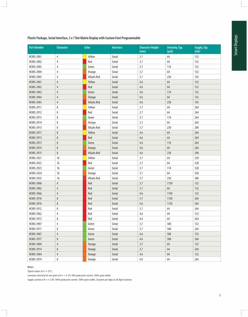
3 mm (T1) LED Lamps — Standard Current
HLMP-1301-G0002 GaP Red 626 60° Tinted, Diff used 8.6 11 1.9 10 n/aHLMP-1321 GaP Red 626 45° Tinted, Non-diff used 8.6 30 1.9 10 n/aHLMP-1340 GaP Red 626 45° Micro-tinted, Non-diff used 8.6 30 1.9 20 n/aHLMP-1401-E0000 GaP Yellow 585 60° Tinted, Diff used 3.6 6 2 10 E, FHLMP-1440 GaP Yellow 585 45° Micro-tinted, Non-diff used 23.5 45 2.1 20 H, IHLMP-1503 GaP Green 569 60° Tinted, Diff used 4.2 8.5 2 10 D, EHLMP-1521 GaP Green 569 45° Tinted, Non-diff used 6.7 22 2.1 10 n/aHLMP-1540 GaP Green 569 45° Untinted, Non-diff used 27.3 45 2.2 20 I, JHLMP-K101 AlGaAs Red 637 60° Tinted, Diff used 22 45 1.8 20 n/aHLMP-K105 AlGaAs Red 637 45° Untinted, Non-diff used 35.2 65 1.8 20 n/aHLMP-K640 GaP Green 560 45° Untinted, Non-diff used 4.2 21 2.2 20 n/aHLMP-KB45-A0000 GaN Blue 462 40° Untinted, Non-diff used 30 45 4 20 n/a
3 mm (T1) LED Lamps — Autoinsertable
HLMP-NG05 AlInGaP Red 626 45° Micro-tinted, Non-diff used 90.2 – 1.90 20 n/aHLMP-NG07 AlInGaP Red 626 60° Micro-tinted, Non-diff used 90.2 – 1.90 20 n/aHLMP-NL06 AlInGaP Amber 590 60° Micro-tinted, Non-diff used 90.2 – 2.02 20 n/aHLMP-NM30 InGaN Green 527 30° Untinted, Non-diff used 180 1000 3.8 20 n/aHLMP-NS30 InGaN Blue 470 30° Untinted, Non-diff used 240 550 3.6 20 n/a
3 mm (T1) 5V, 12V Integrated Resistor LED Lamps
HLMP-1621[1] GaP Yellow 585 60° Tinted, Diff used 2.2 8 8 – n/aHLMP-1640-B00A2 [2] GaP Green 589 60° Tinted, Diff used 1.6 8 8 – n/a
Notes: 1. Operating Voltage = 12 V. 2. Operating Voltage = 5V.
5 mm (T1 3/4) LED Lamps — Standard Current
HLMP-3301 GaP Red 626 60° Tinted, Diff used 5.4 7 1.9 10 F, GHLMP-3401 GaP Yellow 585 60° Tinted, Diff used 5.7 8 2 10 E, FHLMP-3507 GaP Green 569 60° Tinted, Diff used 4.2 5.2 2.1 10 E, FHLMP-3950 GaP Green 569 24° Micro-tinted, Non-diff used 111.7 265 2.2 20 n/aHLMP-C008-U0000 AlInGaP Red 626 8° Untinted, Non-diff used 2900 6000 1.9 20 n/aHLMP-C025-P0000 AlInGaP Red 626 25° Untinted, Non-diff used 500 1000 1.9 20 n/aHLMP-C208-S0000 AlInGaP Amber 590 8° Untinted, Non-diff used 2600 3000 1.9 20 n/aHLMP-C225-O0000 AlInGaP Amber 590 25° Untinted, Non-diff used 450 800 1.9 20 n/aHLMP-C608-R0000 AlInGaP Red 635 8° Untinted, Non-diff used 1000 2000 1.9 20 n/aHLMP-C625-P0000 AlInGaP Red 635 25° Untinted, Non-diff used 500 700 1.9 20 n/aHLMP-DB25-B0000 GaN Blue 462 25° Untinted, Non-diff used 40 100 4 20 n/aHLMP-DM25-J0000 InGaN Green 527 25° Untinted, Non-diff used 240 970 3.8 20 n/aHLMP-DS25-F0000 InGaN Blue 470 25° Untinted, Non-diff used 110 260 3.6 20 n/a
5 mm (T1 3/4) LED Lamps — Low Current
HLMP-4700 GaP Red 626 50° Tinted, Diff used 1.3 2.3 1.8 2 n/aHLMP-4719 GaP Yellow 585 50° Tinted, Diff used 0.9 2.1 1.9 2 n/aHLMP-4740 GaP Green 569 50° Tinted, Diff used 1 2.3 1.8 2 n/aHLMP-D150 AlGaAs Red 637 65° Tinted, Diff used 1.3 3 1.6 1 n/a
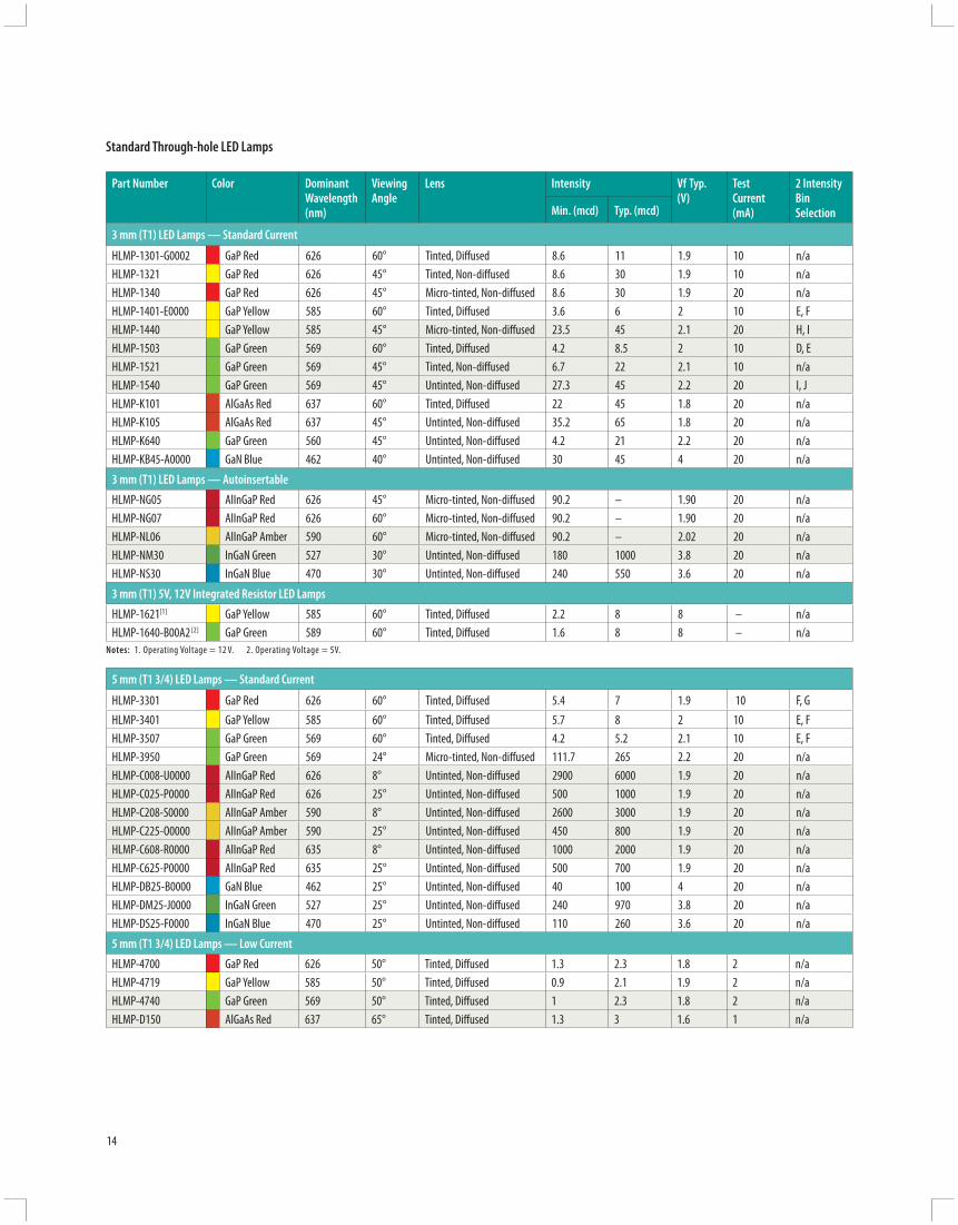
Standard Through-hole LED Lamps
15
Thro
ugh-
hole
Lam
ps
Bin ID
Yellow/Amber
Iv in mcd Color Bin Wavelength (nm) Bin ID Iv in mcd
Min. Max.Yellow
Min. Max.Red/Orange
Min. Max.
A 1.0 1.6 1 582 584.5 A 0.6 0.9B 1.6 2.5 3 584.5 587 B 0.9 1.5C 2.5 4.0 2 587 589.5 C 1.5 2.4D 4.0 6.5 4 589.5 592 D 2.4 3.8E 6.5 10.3 5 592 593.0 E 3.8 6.1F 10.3 16.6
AmberF 6.1 9.7
G 16.6 26.5 G 9.7 15.5H 26.5 42.3 3 584.5 587 H 15.5 24.8I 42.3 67.7 2 587 589.5 I 24.8 39.6J 67.7 108.2 4 589.5 592 J 39.6 63.4K 108.2 173.2 6 592 594.5 K 63.4 101.5L 173.2 250 7 594.5 597 L 101.5 162.4M 250 360 M 162.4 234.6N 360 510 N 234.6 340.0O 510 800 O 340 540P 800 1250 P 540 850Q 1250 1800 Q 850 1200R 1800 2900 R 1200 1700S 2900 4700 S 1700 2400T 4700 7200 T 2400 3400U 7200 11700 U 3400 4900V 11700 18000 V 4900 7100W 18000 27000 W 8100 10200
X 10200 14800Y 14800 21400Z 21400 30900
Maximum Tolerance for each bin limit is +/- 18%
Maximum Tolerance for each color bin limit is +/- 0.5 nm
Part Number
Color Dominant Wavelength (nm)
Viewing Angle
Lens Intensity Vf Typ. (V)
Test Current (mA)
2 Intensity Bin SelectionMin. (mcd) Typ. (mcd)
2 mm x 5 mm Rectangular LED Lamps
HLMP-S201 GaP Red 626 110° Tinted, Diff used 3.4 7.5 1.9 20 n/a
HLMP-S301 GaP Yellow 585 110° Tinted, Diff used 2.2 4 2.1 20 n/a
HLMP-S501 GaP Green 569 110° Tinted, Diff used 4.2 8 2.2 20 n/a
5 mm (T1 3/4) LED Lamps — Bicolor
HLMP-4000 GaP Green 570 65 Untinted, Diff used 4.2 – 2.2 10 n/a
GaP Red 626 65 Untinted, Diff used 2.1 – 1.9 10 n/a
HLMP-4015 Gap Green 570 65 Untinted, Non-Diff used 20 – 2.2 20 n/a
GaP Yellow 585 65 Untinted, Non-Diff used 20 – 2.6 20 n/a
Standard Through-hole Lamps
Through-hole LEDs
Standard Intensity Categories (approx. 2:1 bins)
Maximum Tolerance for each bin limit is +/- 18%
Maximum Tolerance for each color bin limit is +/- 0.5 nm

16
Colors: Blue (InGaN/GaN) InGaN Green
Bin ID Iv in mcd Bin ID Color
Green/ Emerald Green
Wavelength (nm) Color Bin Wavelength (nm) Color Bin Wavelength (nm)
Min. Max. Min. Max. Green Color
Min. Max. Blue Color
Min. Max.
A 30.0 40.0 A 1.1 1.8 9 552.5 555.5 1 460.0 464.0
B 40.0 50.0 B 1.8 2.9 8 555.5 558.5 2 464.0 468.0
C 50.0 65.0 C 2.9 4.7 7 558.5 561.5 3 468.0 472.0
D 65.0 85.0 D 4.7 7.6 6 561.5 564.5 4 472.0 476.0
E 85.0 110.0 E 7.6 12.0 5 564.5 567.5 5 476.0 480.0
F 110.0 140.0 F 12.0 19.1 4 567.5 570.5 6 480.0 484.0
G 140.0 180.0 G 19.1 30.7 3 570.5 573.5 Green ColorH 180.0 240.0 H 30.7 49.1 2 573.5 576.5
J 240.0 310.0 I 49.1 78.5 1 520.0 530.0
K 310.0 400.0 J 78.5 125.7 2 530.0 540.0
L 400.0 520.0 K 125.7 201.1 3 520.0 525.0
M 520.0 680.0 L 201.1 289 4 525.0 530.0
N 680.0 880.0 M 289 417 5 530.0 535.0
P 880.0 1150.0 N 417 680 6 535.0 540.0
Q 1150.0 1500.0 O 680 1100
R 1500.0 1900.0 P 1100 1800
S 1900.0 2500.0 Q 1800 2700
T 2500.0 3200.0 R 2700 4300
U 3200.0 4200.0 S 4300 6800
V 4200.0 5500.0 T 6800 10800
W 5500.0 7200.0 U 10800 16000
X 7200.0 9300.0 V 16000 25000
Y 9300.0 12000.0 W 25000 40000
Z 12000.0 16000.0
1 16000.0 21000.0
2 21000.0 27000.0
3 27000.0 35000.0
4 35000.0 45000.0
5 45000.0 59000.0
Tolerance for each bin limit is ±15%.
Standard Through-hole Lamps
Through-hole LEDsStandard Intensity Categories (approx. 2:1 bins)
Maximum Tolerance for each bin limit is +/- 18%
Maximum Tolerance for each color bin limit is +/- 0.5 nm
Tolerance for each bin limit is ±2%.

17
Thro
ugh-
hole
Lam
ps
Part numbers in BOLD are recommended for new designs.
Part Number
Color Dominant Wavelength (nm) Intensity (mcd) @ 20 mA Leads with Stand-off s
Min. Max.
Precision Optical Performance AllnGaP 5 mm Round LED Lamps
6° Viewing Angle
HLMP-EG08-T0000 Red 626 2500 – No
HLMP-EG08-WZ000 Red 626 5500 16000 No
HLMP-EG08-X1000 Red 626 7200 21000 No
HLMP-EG10-T0000 Red 626 2500 – Yes
HLMP-EG10-WZ000 Red 626 5500 16000 Yes
HLMP-EG10-X1000 Red 626 7200 21000 Yes
HLMP-EH08-X1000 Red-Orange 615 7200 21000 No
HLMP-EJ08-X1000 Orange 605 7200 21000 No
HLMP-EJ10-X1000 Orange 605 7200 21000 Yes
HLMP-EL08-T0000 Amber 590 2500 – No
HLMP-EL08-VY000 Amber 590 4200 12000 No
HLMP-EL08-WZ000 Amber 590 5500 16000 No
HLMP-EL10-T0000 Amber 590 2500 – Yes
HLMP-EL10-VY000 Amber 590 4200 12000 Yes
High Brightness Lamps

18
Part numbers in BOLD are recommended for new designs.
* HLMP-xLxx-xxK00 are selected to Amber color bins 2 and 4 only.
Part Number
Color Dominant Wavelength (nm) Intensity (mcd) @ 20 mA Leads with Stand-off s
Min. Max.
Precision Optical Performance AllnGaP 5 mm Round LED Lamps
15° Viewing Angle
HLMP-EG15-N0000 Red 626 680 – No
HLMP-EG15-QT000 Red 626 1150 3200 No
HLMP-EG15-RU000 Red 626 1500 4200 No
HLMP-EG15-TW000 Red 626 2500 7200 No
HLMP-EG15-UX000 Red 626 3200 9300 No
HLMP-EG17-N0000 Red 626 680 – Yes
HLMP-EG17-QT000 Red 626 1150 3200 Yes
HLMP-EG17-TW000 Red 626 2500 7200 Yes
HLMP-EG17-UX000 Red 626 3200 9300 Yes
HLMP-EH15-RU000 Red-Orange 615 1500 4200 No
HLMP-EH15-TW000 Red-Orange 615 2500 7200 No
HLMP-EH15-UX000 Red-Orange 615 3200 9300 No
HLMP-EH17-TW000 Red-Orange 615 2500 7200 Yes
HLMP-EH17-UX000 Red-Orange 615 3200 9300 Yes
HLMP-EJ15-QT000 Orange 605 1150 3200 No
HLMP-EJ17-QT000 Orange 605 1150 3200 Yes
HLMP-EL15-PS000 Amber 590 880 2500 No
HLMP-EL15-QSK00* Amber 590 1150 2500 No
HLMP-EL15-QT000 Amber 590 1150 3200 No
HLMP-EL15-TW000 Amber 590 2500 7200 No
HLMP-EL15-TWK00 Amber 590 2500 7200 No
HLMP-EL15-UX000 Amber 590 3200 9300 No
HLMP-EL15-VY000 Amber 590 4200 12000 No
HLMP-EL15-VYK00 Amber 590 4200 12000 No
HLMP-EL17-M0000 Amber 590 520 – Yes
HLMP-EL17-TW000 Amber 590 2500 7200 Yes
HLMP-EL17-UX000 Amber 590 3200 9300 Yes
HLMP-EL17-VY000 Amber 590 4200 12000 Yes
High Brightness Lamps

19
Thro
ugh-
hole
Lam
ps
Part numbers in BOLD are recommended for new designs.
Part Number
Color Dominant Wavelength (nm) Intensity (mcd) @ 20 mA Leads with Stand-off s
Min. Max.
Precision Optical Performance AllnGaP 5 mm Round LED Lamps
23° Viewing Angle
HLMP-EG24-M0000 Red 626 520 – No
HLMP-EG24-PS000 Red 626 880 2500 No
HLMP-EG24-QT000 Red 626 1150 3200 No
HLMP-EG26-M0000 Red 626 520 – Yes
HLMP-EH24-QT000 Red-Orange 615 1150 3200 No
HLMP-EH24-SV000 Red-Orange 615 1900 5500 No
HLMP-EH26-SV000 Red-Orange 615 1900 5500 Yes
HLMP-EJ24-QT000 Orange 605 1150 3200 No
HLMP-EL24-L0000 Amber 590 400 – No
HLMP-EL24-NR000 Amber 590 680 1900 No
HLMP-EL24-PS000 Amber 590 880 2500 No
HLMP-EL24-RU000 Amber 590 1150 4200 No
HLMP-EL24-RUK00 Amber 590 1150 4200 No
HLMP-EL24-SV000 Amber 590 1900 5500 No
HLMP-EL24-SVK00 Amber 590 1900 5500 No
HLMP-EL24-TW000 Amber 590 2500 7200 No
HLMP-EL24-TWK00 Amber 590 2500 7200 No
HLMP-EL26-L0000 Amber 590 400 – Yes
HLMP-EL26-PS000 Amber 590 880 2500 Yes
HLMP-EL26-RU000 Amber 590 1150 4200 Yes
HLMP-EL26-SV000 Amber 590 1900 5500 Yes
HLMP-EL26-TW000 Amber 590 2500 7200 Yes
High Brightness Lamps

20
Part numbers in BOLD are recommended for new designs.
Part Number
Color Dominant Wavelength (nm) Intensity (mcd) @ 20 mA Leads with Stand-off s
Min. Max.
Precision Optical Performance AllnGaP 5 mm Round LED Lamps
30° Viewing Angle
HLMP-EG30-K0000 Red 626 310 – No
HLMP-EG30-MQ000 Red 626 520 1500 No
HLMP-EG30-NR000 Red 626 680 1900 No
HLMP-EG30-QT000 Red 626 1150 3200 No
HLMP-EG32-K0000 Red 626 310 – Yes
HLMP-EG32-MQ000 Red 626 520 1500 Yes
HLMP-EG32-NR000 Red 626 680 1900 Yes
HLMP-EG32-QT000 Red 626 1150 3200 Yes
HLMP-EH30-QT000 Red-Orange 615 1150 3200 No
HLMP-EH30-RU000 Red-Orange 615 1500 4200 No
HLMP-EH32-QT000 Red-Orange 615 1150 3200 Yes
HLMP-EH32-RU000 Red-Orange 615 1500 4200 Yes
HLMP-EJ30-NR000 Orange 605 680 1900 No
HLMP-EL30-K0000 Amber 590 310 – No
HLMP-EL30-MQ000 Amber 590 520 1500 No
HLMP-EL30-QT000 Amber 590 1150 3200 No
HLMP-EL30-QTK00 Amber 590 1150 3200 No
HLMP-EL30-SV000 Amber 590 1900 5500 No
HLMP-EL30-SVK00 Amber 590 1900 5500 No
HLMP-EL32-K0000 Amber 590 310 – Yes
HLMP-EL32-NR000 Amber 590 680 1900 Yes
HLMP-EL32-QT000 Amber 590 1150 3200 Yes
HLMP-EL32-SV000 Amber 590 1900 5500 Yes
High Brightness Lamps

21
Thro
ugh-
hole
Lam
ps
Part numbers in BOLD are recommended for new designs.
* HLMP-xLxx-xxK00 are selected to Amber color bins 2 and 4 only.
Part Number
Color Dominant Wavelength (nm) Intensity (mcd) @ 20 mA Leads with Stand-off s
Min. Max.
Precision Optical Performance AllnGaP II 5 mm Round LED Lamps
15° Viewing Angle HLMP-ED16-S0000 Red 630 1900 – NoHLMP-ED16-TW000 Red 630 2500 7200 NoHLMP-ED18-S0000 Red 630 1900 – Yes
HLMP-ED18-TW000 Red 630 2500 7200 No
HLMP-EH16-UX000 Red-Orange 615 3200 9300 NoHLMP-EH18-UX000 Red-Orange 615 3200 9300 YesHLMP-EL16-S0000 Amber 592 1900 – NoHLMP-EL16-VY000 Amber 592 4200 12000 NoHLMP-EL18-S0000 Amber 592 1900 – YesHLMP-EL18-VY000 Amber 592 4200 12000 Yes
23° Viewing Angle HLMP-ED25-R0000 Red 630 1500 – NoHLMP-ED25-SV000 Red 630 1900 5500 NoHLMP-ED25-TW000 Red 630 2500 7200 NoHLMP-ED27-R0000 Red 630 1500 – YesHLMP-ED27-SV000 Red 630 1900 5500 YesHLMP-ED27-TW000 Red 630 2500 7200 YesHLMP-EH25-SV000 Red-Orange 615 1900 5500 NoHLMP-EH25-TW000 Red-Orange 615 2500 7200 NoHLMP-EL25-Q0000 Amber 592 1150 – NoHLMP-EL25-SUK00 Amber 592 1900 4200 NoHLMP-EL25-SV000 Amber 592 1900 5500 NoHLMP-EL25-SVK00 Amber 592 1900 5500 NoHLMP-EL25-TW000 Amber 592 2500 5500 NoHLMP-EL27-Q0000 Amber 592 1150 – YesHLMP-EL27-SV000 Amber 592 1900 5500 YesHLMP-EL27-TW000 Amber 592 2500 7200 Yes
30° Viewing Angle HLMP-ED31-Q0000 Red 630 1150 – NoHLMP-ED31-SV000 Red 630 1900 5500 NoHLMP-ED33-Q0000 Red 630 1150 – YesHLMP-ED33-SV000 Red 630 1900 5500 YesHLMP-EH31-SV000 Red-Orange 615 1900 5500 NoHLMP-EH33-RU000 Red-Orange 615 1500 4200 YesHLMP-EL31-P0000 Amber 592 880 – NoHLMP-EL31-SV000 Amber 592 1900 5500 NoHLMP-EL31-SVK00* Amber 592 1900 5500 NoHLMP-EL33-P0000 Amber 592 880 – YesHLMP-EL33-SV000 Amber 592 1900 5500 Yes
High Brightness Lamps
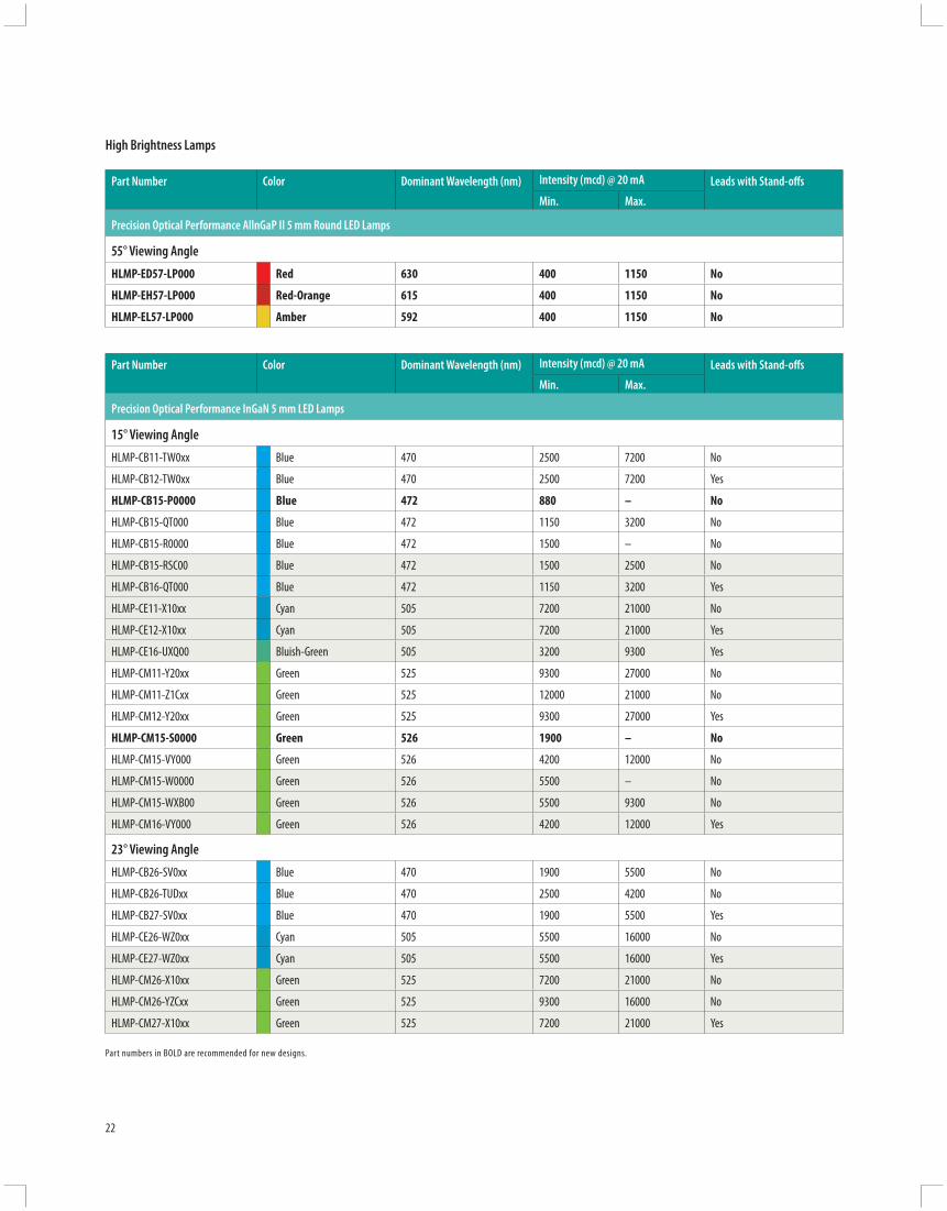
22
Part numbers in BOLD are recommended for new designs.
Part Number
Color Dominant Wavelength (nm) Intensity (mcd) @ 20 mA Leads with Stand-off s
Min. Max.
Precision Optical Performance AllnGaP II 5 mm Round LED Lamps
55° Viewing Angle
HLMP-ED57-LP000 Red 630 400 1150 No
HLMP-EH57-LP000 Red-Orange 615 400 1150 No
HLMP-EL57-LP000 Amber 592 400 1150 No
Part Number Color Dominant Wavelength (nm) Intensity (mcd) @ 20 mA Leads with Stand-off s
Min. Max.
Precision Optical Performance InGaN 5 mm LED Lamps
15° Viewing Angle
HLMP-CB11-TW0xx Blue 470 2500 7200 No
HLMP-CB12-TW0xx Blue 470 2500 7200 Yes
HLMP-CB15-P0000 Blue 472 880 – No
HLMP-CB15-QT000 Blue 472 1150 3200 No
HLMP-CB15-R0000 Blue 472 1500 – No
HLMP-CB15-RSC00 Blue 472 1500 2500 No
HLMP-CB16-QT000 Blue 472 1150 3200 Yes
HLMP-CE11-X10xx Cyan 505 7200 21000 No
HLMP-CE12-X10xx Cyan 505 7200 21000 Yes
HLMP-CE16-UXQ00 Bluish-Green 505 3200 9300 Yes
HLMP-CM11-Y20xx Green 525 9300 27000 No
HLMP-CM11-Z1Cxx Green 525 12000 21000 No
HLMP-CM12-Y20xx Green 525 9300 27000 Yes
HLMP-CM15-S0000 Green 526 1900 – No
HLMP-CM15-VY000 Green 526 4200 12000 No
HLMP-CM15-W0000 Green 526 5500 – No
HLMP-CM15-WXB00 Green 526 5500 9300 No
HLMP-CM16-VY000 Green 526 4200 12000 Yes
23° Viewing Angle
HLMP-CB26-SV0xx Blue 470 1900 5500 No
HLMP-CB26-TUDxx Blue 470 2500 4200 No
HLMP-CB27-SV0xx Blue 470 1900 5500 Yes
HLMP-CE26-WZ0xx Cyan 505 5500 16000 No
HLMP-CE27-WZ0xx Cyan 505 5500 16000 Yes
HLMP-CM26-X10xx Green 525 7200 21000 No
HLMP-CM26-YZCxx Green 525 9300 16000 No
HLMP-CM27-X10xx Green 525 7200 21000 Yes
High Brightness Lamps

23
Thro
ugh-
hole
Lam
ps
Part numbers in BOLD are recommended for new designs.
Part Number
Color Dominant Wavelength (nm) Intensity (mcd) @ 20 mA Leads with Stand-off s
Min. Max.
30° Viewing Angle
HLMP-CB30-K0000 Blue 472 310 – No
HLMP-CB30-M0000 Blue 472 520 – No
HLMP-CB30-NRG00 Blue 472 680 1900 No
HLMP-CB30-PQCDD Blue 472 880 1500 No
HLMP-CB31-NRG00 Blue 472 680 1900 Yes
HLMP-CB36-QT0xx Blue 470 1500 4200 No
HLMP-CB36-RSBxx Blue 470 1500 2500 No
HLMP-CB37-RSDxx Blue 470 1500 2500 Yes
HLMP-CB37-RU0xx Blue 470 1500 4200 Yes
HLMP-CE30-RSC00 Bluish-Green 505 1500 2500 No
HLMP-CE36-WZ0xx Cyan 505 5500 16000 No
HLMP-CE37-WZ0xx Cyan 505 5500 16000 Yes
HLMP-CM30-M0000 Green 526 520 – No
HLMP-CM30-RSB00 Green 526 1500 2500 No
HLMP-CM30-S0000 Green 526 1900 – No
HLMP-CM30-TUB00 Green 526 2500 4200 No
HLMP-CM30-TUCDD Green 526 2500 4200 No
HLMP-CM30-TW000 Green 526 2500 7200 No
HLMP-CM30-TWA00 Green 526 2500 7200 No
HLMP-CM30-UVA00 Green 526 3200 5500 No
HLMP-CM31-TUCDD Green 526 2500 4200 Yes
HLMP-CM31-TW000 Green 526 2500 7200 Yes
HLMP-CM31-TWA00 Green 526 2500 7200 Yes
HLMP-CM36-X10xx Green 525 7200 21000 No
HLMP-CM36-XYCxx Green 525 7200 12000 No
HLMP-CM37-X10xx Green 525 7200 21000 Yes
HLMP-CM37-XYCxx Green 525 7200 12000 Yes
HLMP-CM37-XYDxx Green 525 7200 12000 Yes
High Brightness Lamps
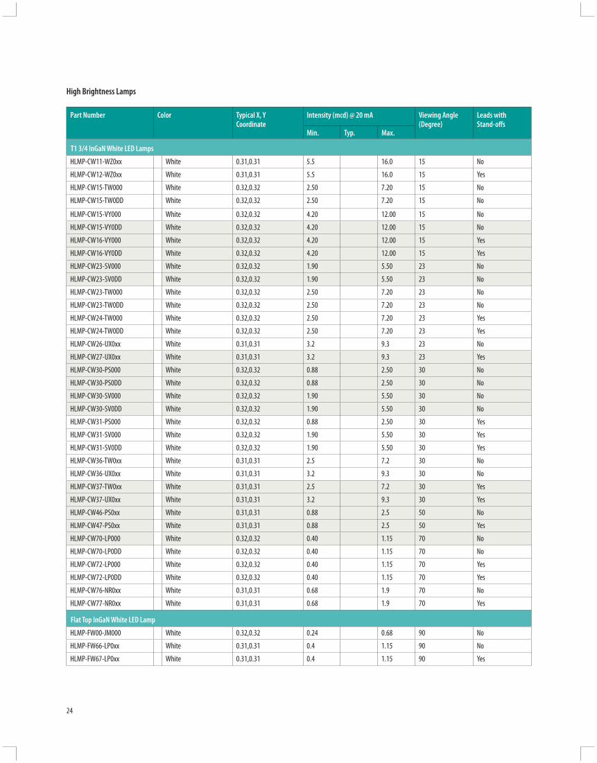
24
Part Number Color Typical X, Y Coordinate
Intensity (mcd) @ 20 mA Viewing Angle (Degree)
Leads with Stand-off s
Min. Typ. Max.
T1 3/4 InGaN White LED Lamps
HLMP-CW11-WZ0xx White 0.31,0.31 5.5 16.0 15 No
HLMP-CW12-WZ0xx White 0.31,0.31 5.5 16.0 15 Yes
HLMP-CW15-TW000 White 0.32,0.32 2.50 7.20 15 No
HLMP-CW15-TW0DD White 0.32,0.32 2.50 7.20 15 No
HLMP-CW15-VY000 White 0.32,0.32 4.20 12.00 15 No
HLMP-CW15-VY0DD White 0.32,0.32 4.20 12.00 15 No
HLMP-CW16-VY000 White 0.32,0.32 4.20 12.00 15 Yes
HLMP-CW16-VY0DD White 0.32,0.32 4.20 12.00 15 Yes
HLMP-CW23-SV000 White 0.32,0.32 1.90 5.50 23 No
HLMP-CW23-SV0DD White 0.32,0.32 1.90 5.50 23 No
HLMP-CW23-TW000 White 0.32,0.32 2.50 7.20 23 No
HLMP-CW23-TW0DD White 0.32,0.32 2.50 7.20 23 No
HLMP-CW24-TW000 White 0.32,0.32 2.50 7.20 23 Yes
HLMP-CW24-TW0DD White 0.32,0.32 2.50 7.20 23 Yes
HLMP-CW26-UX0xx White 0.31,0.31 3.2 9.3 23 No
HLMP-CW27-UX0xx White 0.31,0.31 3.2 9.3 23 Yes
HLMP-CW30-PS000 White 0.32,0.32 0.88 2.50 30 No
HLMP-CW30-PS0DD White 0.32,0.32 0.88 2.50 30 No
HLMP-CW30-SV000 White 0.32,0.32 1.90 5.50 30 No
HLMP-CW30-SV0DD White 0.32,0.32 1.90 5.50 30 No
HLMP-CW31-PS000 White 0.32,0.32 0.88 2.50 30 Yes
HLMP-CW31-SV000 White 0.32,0.32 1.90 5.50 30 Yes
HLMP-CW31-SV0DD White 0.32,0.32 1.90 5.50 30 Yes
HLMP-CW36-TW0xx White 0.31,0.31 2.5 7.2 30 No
HLMP-CW36-UX0xx White 0.31,0.31 3.2 9.3 30 No
HLMP-CW37-TW0xx White 0.31,0.31 2.5 7.2 30 Yes
HLMP-CW37-UX0xx White 0.31,0.31 3.2 9.3 30 Yes
HLMP-CW46-PS0xx White 0.31,0.31 0.88 2.5 50 No
HLMP-CW47-PS0xx White 0.31,0.31 0.88 2.5 50 Yes
HLMP-CW70-LP000 White 0.32,0.32 0.40 1.15 70 No
HLMP-CW70-LP0DD White 0.32,0.32 0.40 1.15 70 No
HLMP-CW72-LP000 White 0.32,0.32 0.40 1.15 70 Yes
HLMP-CW72-LP0DD White 0.32,0.32 0.40 1.15 70 Yes
HLMP-CW76-NR0xx White 0.31,0.31 0.68 1.9 70 No
HLMP-CW77-NR0xx White 0.31,0.31 0.68 1.9 70 Yes
Flat Top InGaN White LED Lamp
HLMP-FW00-JM000 White 0.32,0.32 0.24 0.68 90 No
HLMP-FW66-LP0xx White 0.31,0.31 0.4 1.15 90 No
HLMP-FW67-LP0xx White 0.31,0.31 0.4 1.15 90 Yes
High Brightness Lamps

25
Thro
ugh-
hole
Lam
ps
Part numbers in BOLD are recommended for new designs.
Part Number
Package Drawing
Color Dominant Wavelength (nm)
Intensity (mcd) @ 20 mA Leads with Stand-off s
Tint Leadframe Orientation
Min. Max.
Precision Optical Performance AlInGaP 4 mm Oval LED Lamps
60° x 120° Viewing Angle HLMP-RG10-JM000 F Red 626 240 680 Yes Red ParallelHLMP-RL10-LP000 F Amber 590 400 1150 Yes Amber ParallelHLMP-SG10-JM000 E Red 626 240 680 Yes Red PerpendicularHLMP-SL10-LP000 E Amber 590 400 1150 Yes Amber Perpendicular
Precision Optical Performance AllnGaP II 4 mm Oval LED Lamps
60°x 120° Viewing Angle HLMP-RD11-J0000 F Red 630 240 – Yes Amber ParallelHLMP-RD11-LP000 F Red 630 400 1150 Yes Red ParallelHLMP-RL11-H0000 F Amber 592 180 – Yes Amber ParallelHLMP-RL11-LP000 F Amber 592 400 1150 Yes Amber ParallelHLMP-SD11-J0000 E Red 630 240 – Yes Red PerpendicularHLMP-SD11-LP000 E Red 630 400 1150 Yes Red PerpendicularHLMP-SL11-H0000 E Amber 592 180 – Yes Amber PerpendicularHLMP-SL11-LP000 E Amber 592 400 1150 Yes Amber Perpendicular
50° x 100° Viewing AngleHLMP-LD15-MNTxx A Red 630 520 880 Yes RedHLMP-LD15-MQTxx A Red 630 520 1500 Yes RedHLMP-LD15-NPTxx A Red 630 680 1150 Yes RedHLMP-LD15-NRTxx A Red 630 680 1900 Yes Red
High Brightness Lamps
Part Number
Package Drawing
Color Dominant Wavelength (nm)
Intensity (mcd) @ 20 mA Leads with Stand-off s
Min. Max.
Precision Optical Performance InGaN 4 mm Oval LED Lamps
50° x 100° Viewing Angle HLMP-LB11-FJ000 D Blue 472 110 310 YesHLMP-LB11-HJCDD D Blue 472 180 310 YesHLMP-LB11-HL000 D Blue 472 180 520 YesHLMP-LB11-JKCDD D Blue 472 240 400 YesHLMP-LB17-LPxxx B Blue 470 400 1150 YesHLMP-LM11-LP000 D Green 526 400 1150 YesHLMP-LM11-MNCDD D Green 526 520 880 YesHLMP-LM11-NR000 D Green 526 680 1900 YesHLMP-LM11-PQCDD D Green 526 880 1500 YesHLMP-LM11-QRCDD D Green 526 1150 1900 YesHLMP-LM17-SVxxx B Green 525 1900 5500 Yes
Part Number
Package Drawing
Color Dominant Wavelength (nm)
Intensity (mcd) @ 20 mA Leads with Stand-off s
Tint Leadframe Orientation
Min. Max.
Precision Optical Performance lnGaN 4 mm Oval LED Lamps
60° x 120° Viewing Angle HLMP-RB11-D0000 F Blue 472 65 – Yes Blue ParallelHLMP-RB11-H0000 F Blue 472 180 – Yes Blue ParallelHLMP-RM11-H0000 F Green 526 180 – Yes Green ParallelHLMP-RM11-M0000 F Green 526 520 – Yes Green ParallelHLMP-SB11-H00xx E Blue 472 180 – Yes Blue PerpendicularHLMP-SM11-LP0xx E Green 526 400 1150 Yes Green Perpendicular

26
Part Number
Package Drawing
Color Dominant Wavelength (nm)
Intensity (mcd) @ 20 mA Leads with Stand-off s
Tint Leadframe Orientation
Min. Max.
Precision Optical Performance AlInGaP II 5 mm Oval LED Lamps
35° x 70° Viewing AngleHLMP-AD06-P0000 W Red 630 880 – No Red ParallelHLMP-AD16-P0000 X Red 630 880 – Yes Red ParallelHLMP-AD85-RUOxx 1 Red 630 1500 4200 No RedHLMP-AD87-RUOxx 1 Red 630 1500 4200 Yes RedHLMP-AL06-N0000 W Amber 592 680 – No Amber ParallelHLMP-AL16-N0000 X Amber 592 680 – Yes Amber ParallelHLMP-BD06-P0000 Y Red 630 880 – No Red PerpendicularHLMP-BD16-P0000 Z Red 630 880 – Yes Red PerpendicularHLMP-BL06-N0000 Y Amber 592 680 – No Amber PerpendicularHLMP-BL16-N0000 Z Amber 592 680 – Yes Amber Perpendicular
50° x 100° Viewing Angle
HLMP-HD55-NR0xx H Red 630 680 1900 Yes Red Parallel
HLMP-HD57-NR000 G Red 630 680 1900 Yes Red Parallel
Precision Optical Performance InGaN 5 mm Oval LED Lamps
35° x 70° Viewing AngleHLMP-AB86-MQ0xx 1 Blue 470 520 1500 No BlueHLMP-AB87-MQ0xx 1 Blue 470 520 1500 Yes BlueHLMP-AM86-TW0xx 1 Green 525 2500 7200 No GreenHLMP-AM87-TW0xx 1 Green 525 2500 7200 Yes GreenHLMP-BB11-J0000 Z Blue 472 240 – Yes Blue PerpendicularHLMP-BB11-K0000 Z Blue 472 310 – Yes Blue PerpendicularHLMP-BM11-L0000 Z Green 526 400 – Yes Green PerpendicularHLMP-BM11-Q0000 Z Green 526 1150 – Yes Green Perpendicular
High Brightness Lamps
Precision Optical Performance AllnGaP 5 mm Oval LED Lamps
35° x 70° Viewing AngleHLMP-AL01-NR000 W Amber 590 680 1900 No Amber ParallelHLMP-AL11-NR000 X Amber 590 680 1900 Yes Amber ParallelHLMP-BL01-NR000 Y Amber 590 680 1900 No Amber PerpendicularHLMP-BL11-NR000 Z Amber 590 680 1900 Yes Amber Perpendicular
Part Number Package Drawing
Color Dominant Wavelength (nm)
Intensity (cd) @ 20 mA Leads with Stand-off s
Min. Max.
Precision Optical Performance InGaN 5 mm Oval LED Lamps
40° x 100° Viewing AngleHLMP-HB55-FJ000 G Blue 472 110 310 YesHLMP-HB55-HJCDD G Blue 472 180 310 YesHLMP-HB55-JKCDD G Blue 472 240 400 YesHLMP-HB57-KN0xx J Blue 470 310 880 YesHLMP-HB57-LMCxx J Blue 470 400 680 YesHLMP-HB57-LP0xx J Blue 470 400 1150 YesHLMP-HM55-MQ000 G Green 526 520 1500 YesHLMP-HM55-NPCDD G Green 526 680 1150 YesHLMP-HM55-PQCDD G Green 526 880 1500 YesHLMP-HM57-RSCxx J Green 525 1500 2500 YesHLMP-HM57-RU0xx J Green 525 1500 4200 YesHLMP-HM57-SV0xx J Green 525 1900 5500 Yes

27
Thro
ugh-
hole
Lam
ps
Part Number Package Drawing
Color Dominant Wavelength (nm)
Intensity (mcd) @ 20 mA Leads with Stand-off s
Min. Max.
5 mm Standard Oval Mid Power AlInGaP LEDs
40° x 100° Viewing Angle
HLMP-HD30-SV000 A 626 1900 5500 No
HLMP-HD31-SV000 B 626 1900 5500 Yes
HLMP-HL30-RU000 A 592 1500 4200 No
HLMP-HL31-RU000 B 592 1500 4200 Yes
5 mm Mini Oval Mid Power AlInGaP LEDs
30° x 70° Viewing Angle
HLMP-AD30-UX000 A 626 3200 9300 No
HLMP-AD31-UX000 B 626 3200 9300 Yes
HLMP-AL30-TW000 A 592 2500 7200 No
HLMP-AL31-TW000 B 592 2500 7200 Yes
Bin Name Min. Max.
D 65 85E 85 110F 110 140G 140 180H 180 240J 240 310K 310 400L 400 520M 520 680N 680 880P 880 1150Q 1150 1500R 1500 1900S 1900 2500T 2500 3200U 3200 4200V 4200 5500W 5500 7200X 7200 9300Y 9300 12000Z 12000 160001 16000 21000
Tolerance for each bin limit is ±15%
These intensity and color charts show the various binning information for Precision Optical Performance AlInGaP LEDs. Red and reddish orange devices are not color binned as eyes are less sensitive to wavelength shifts in these color regions.
White Color Bin Limit TablesRank Limits
(Chromaticity Coordinates)
1 x 0.330 0.330 0.356 0.361y 0.360 0.318 0.351 0.385
2 x 0.287 0.296 0.330 0.330y 0. 295 0.276 0.318 0.339
3 x 0.264 0.280 0.296 0.283y 0.267 0.248 0.276 0.305
4 x 0.283 0.287 0.330 0.330y 0.305 0.295 0.339 0.360
Tolerance for each bin limit is ±0.01
High Brightness Lamps
High Brightness LED Lamps Intensity Bin Limits (mcd at 20 mA)
Amber Min. Max.
1 584.5 587.02 587.0 589.54 589.5 592.06 592.0 594.5
Tolerance for each bin limit is ± 0.5 nm
Cyan Min. Max.
1 490 4952 495 5003 500 5054 505 5107 498 5038 503 508
Tolerance for each bin limit is ± 0.5 nm
Color Bin StructureBin ID nm @ 20 mA
Blue Min. Max.
1 460 4642 464 4683 468 4724 472 4765 476 480
Tolerance for each bin limit is ± 0.5 nm
Green Min. Max.
1 520 5242 524 5283 528 5324 532 5365 536 540
Tolerance for each bin limit is ± 0.5 nm

2.0 (0.08) REF.
0.4 ±0.2(0.01 ±0.01)
2.5 ±0.3(0.10 ±0.01)
0.45 ±0.10(0.02 ±0.007)
0.4 ±0.2(0.02 ±0.01)
0.4 + 0.1 0
(0.2 + 0.00 - 0.00
)
3.4 ±0.2(0.13 ±0.01)
CATHODE MARKS
0.65 (0.03) MAX.
3.1 ±0.2(0.12 ±0.01)
4.4 ±0.3(0.17 ±0.01)
3.5 ±0.3(0.14 ±0.01)
5.9 ±0.5(0.23 ±0.02)
23.0(0.91)
1.0 ±0.5(0.04 ±0.02)
SEATING PLANE
NOTES:1. ALL DIMENSIONS ARE IN MILLIMETERS (INCHES).2. LEADS ARE MILD STEEL. SOLDER COATED.3. EPOXY MENISCUS OF 0.8 mm (0.03 in.) MAXIMUM MAY EXTEND TO THE LEADS.
6.10 (0.240)5.59 (0.220)
25.40(1.00)MIN.
0.508 (0.020)SQ. TYP.
RED OR YELLOW ANODE(SHORT LEAD)
1.27 (0.050)NOM.
0.89 (0.035)0.64 (0.025)
9.19 (0.362)8.43 (0.332)
5.08 (0.200)4.57 (0.180)
1.27 (0.050)NOM.
2.54 (0.100)NOM.
FLAT INDICATESANODE
COMMON CATHODE
GREEN ANODE
COMMONCATHODE
1.14 ±0.20(0.0045 ±0.008)
5.00 ±0.20(0.197 ±0.008)
7.00 ±0.20(0.276 ±0.008)
CATHODELEAD
0.50 ±0.10(0.020 ±0.004)SQ. TYP.
2.54 ±0.38(0.100 ±0.015)
5.72 ±0.20(0.225 ±0.008)
CATHODEFLAT
1.00(0.039) MIN.
31.60(1.244) MIN.
1.02 (0.040)NOM.
3.43 (0.135)2.92 (0.115)
24.13(0.95) MIN.
4.70 (0.185)4.19 (0.165)
3.18 (0.125)2.67 (0.105)
2.54 (0.100) NOMINAL1.27 (0.050)NOMINAL
6.35 (0.250)5.58 (0.220)
0.45 (0.018)SQUARE NOMINAL CATHODE
23.0(0.90)MIN.
0.45 (0.018)SQUARE NOMINAL
1.27 (0.050)NOM.
0.89 (0.035)0.64 (0.025)
9.19 (0.352)8.43 (0.332)
5.08 (0.200)4.57 (0.180)
5.18 (0.204)4.93 (0.194)
5.46 (0.215)4.95 (0.195)
1.27 (0.050)NOMINAL
8.00 (0.315)7.37 (0.290)
25.40(1.00)MIN.
28
3 mm (T1) LED Lamps Package 5 mm (T1 3/4) LED Lamps Package 2 x 5 mm Rectangular LED Lamps Package
3 mm (T1) LED Lamps – Autoinsertable Package
5 mm (T1-3/4) LED Lamps - Bicolor 5 mm Flat Top LED Lamps Package
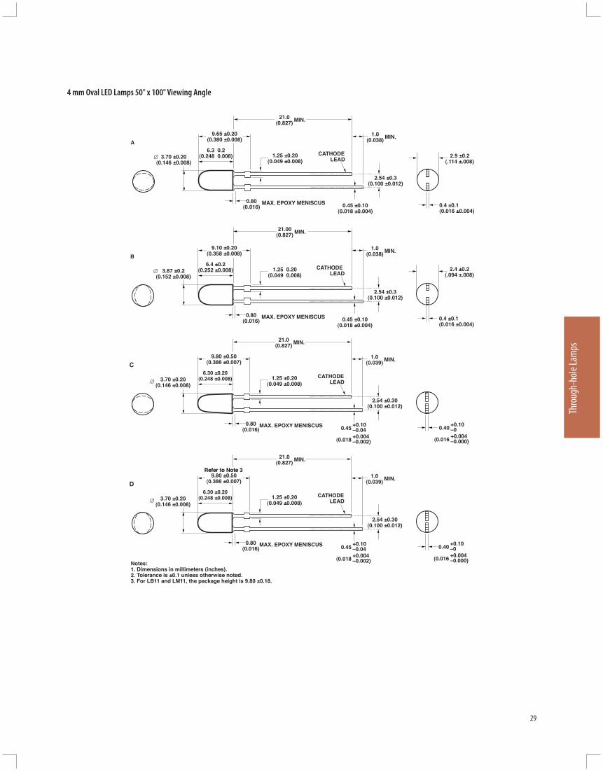
3.70 ±0.20(0.146 ±0.008)
1.25 ±0.20(0.049 ±0.008)
0.80(0.016)
MAX. EPOXY MENISCUS
9.65 ±0.20(0.380 ±0.008)
CATHODELEAD
A6.3 0.2
(0.248 0.008)
2.54 ±0.3(0.100 ±0.012)
21.0(0.827) MIN.
1.0(0.038) MIN.
0.4 ±0.1(0.016 ±0.004)
2.9 ±0.2(.114 ±.008)
0.45 ±0.10(0.018 ±0.004)
3.87 ±0.2(0.152 ±0.008)
1.25 0.20(0.049 0.008)
0.80(0.016)
MAX. EPOXY MENISCUS
9.10 ±0.20(0.358 ±0.008)
CATHODE LEAD
B6.4 ±0.2
(0.252 ±0.008)
2.54 ±0.3(0.100 ±0.012)
21.00(0.827) MIN.
1.0(0.038) MIN.
0.45 ±0.10(0.018 ±0.004)
0.4 ±0.1(0.016 ±0.004)
2.4 ±0.2(.094 ±.008)
3.70 ±0.20(0.146 ±0.008)
1.25 ±0.20(0.049 ±0.008)
0.80(0.016)
MAX. EPOXY MENISCUS
9.80 ±0.50(0.386 ±0.007)
CATHODELEAD
C6.30 ±0.20
(0.248 ±0.008)
2.54 ±0.30(0.100 ±0.012)
21.0(0.827) MIN.
1.0(0.039) MIN.
0.40+0.10–0
(0.016+0.004–0.000)
0.45+0.10–0.04
(0.018+0.004–0.002)
3.70 ±0.20(0.146 ±0.008)
1.25 ±0.20(0.049 ±0.008)
0.80(0.016)
MAX. EPOXY MENISCUS
9.80 ±0.50(0.386 ±0.007)
CATHODELEAD
D6.30 ±0.20
(0.248 ±0.008)
2.54 ±0.30(0.100 ±0.012)
21.0(0.827) MIN.
1.0(0.039) MIN.
0.40+0.10–0
(0.016+0.004–0.000)
0.45+0.10–0.04
(0.018+0.004–0.002)Notes:
1. Dimensions in millimeters (inches).2. Tolerance is ±0.1 unless otherwise noted.3. For LB11 and LM11, the package height is 9.80 ±0.18.
Refer to Note 3
29
Thro
ugh-
hole
Lam
ps
4 mm Oval LED Lamps 50° x 100° Viewing Angle

4.0 ±0.20(0.157 ±0.008)
1.25 ±0.20(0.049 ±0.008)
0.80(0.016)
MAX. EPOXY MENISCUS
9.50 ±0.50(0.374 ±0.007)
0.44 ±0.20(0.017 ±0.008)
CATHODELEAD
E6.30 ±0.20
(0.248 ±0.008)
2.54 ±0.30(0.100 ±0.012)
21.0(0.827) MIN.
1.0(0.039) MIN.
0.40+0.10–0
(0.016+0.004–0.000)
0.45+0.10–0.04
(0.018+0.004–0.002)
4.0 ±0.20(0.157 ±0.008)
1.25 ±0.20(0.049 ±0.008)
0.80(0.016)
MAX. EPOXY MENISCUS
9.50 ±0.50(0.374 ±0.007)
0.44 ±0.20(0.017 ±0.008)
CATHODELEAD
F6.30 ±0.20
(0.248 ±0.008)
2.54 ±0.30(0.100 ±0.012)
21.0(0.827) MIN.
1.0(0.039) MIN.
0.40+0.10–0
(0.016+0.004–0.000)
0.45+0.10–0.04
(0.018+0.004–0.002)DIMENSIONS ARE IN MILLIMETERS (INCHES).
5.20 ±0.25(0.204 ±0.010)
24.00(0.945) MIN.
1.50 MAX.(0.059) MAX.
0.70 (.028)MAX.
1.00(.039)
MIN.
11.90 ±0.50(0.469 ±0.019)
2.54 ±0.25(0.10 ±0.010)
0.50 ±0.10(.020 ±.004)
SQ. TYP.
CATHODE LEAD
7.00(0.275)
1.50 ±0.15(.059 ±.006)
H
Note:1. MEASURED AT BASE OF LENS.
3.80 ±0.25(0.150 ±0.010)
5.20(0.204)
24.00(0.945) MIN.
1.50 MAX.(0.059) MAX.
0.70 (.028)MAX.
1.00(.039)
MIN.
10.85 ±0.50(0.427 ±0.019)
2.54(0.10)
0.50 ±0.10(.020 ±.004)
SQ. TYP.
CATHODE LEAD
7.00(0.275)
1.50 ±0.15(.059 ±.006)
G
Note:1. MEASURED AT BASE OF LENS.
3.80(0.150)
30
4 mm Oval LED Lamps 60° x 120° Viewing Angle
5 mm Oval LED Lamps 50° x 100° Viewing Angle
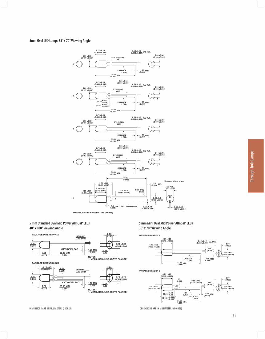
5.00 ±0.20(0.197 ±0.008)
31.60(1.244) MIN.
0.70 (0.028)MAX.
1.00(0.039)
MIN.
8.71 ±0.20(0.343 ±0.008)
2.54 ±0.38(0.100 ±0.015)
0.50 ±0.10(0.020 ±0.004)
SQ. TYP.
CATHODELEAD
5.00 ±0.20(0.197 ±0.008)
31.60(1.244) MIN.
0.70 (0.028)MAX.
1.00(0.039)
MIN.
8.71 ±0.20(0.343 ±0.008)
2.54 ±0.38(0.100 ±0.015)
0.50 ±0.10(0.020 ±0.004)
SQ. TYP.
CATHODELEAD
1.50 ±0.15(0.059 ±0.006)
5.00 ±0.20(0.197 ±0.008)
31.60(1.244) MIN.
0.70 (0.028)MAX.
1.00(0.039)
MIN.
8.71 ±0.20(0.343 ±0.008)
2.54 ±0.38(0.100 ±0.015)
0.50 ±0.10(0.020 ±0.004)
SQ. TYP.
CATHODELEAD
5.00 ±0.20(0.197 ±0.008)
31.60(1.244) MIN.
0.70 (0.028)MAX.
1.00(0.039)
MIN.
8.71 ±0.20(0.343 ±0.008)
2.54 ±0.38(0.100 ±0.015)
0.50 ±0.10(0.020 ±0.004)
SQ. TYP.
CATHODELEAD
1.50 ±0.15(0.059 ±0.006)
W
X
Y
Z
11.70+ 0.13– 0.08
0.461+ 0.005– 0.003 )(
5.20 ±0.20(0.205 ±.008)
1.25 ±0.20(0.049 ±0.008)
0.8(0.032)
MAX. EPOXY MENISCUS
11.50 ±0.20(0.453 ±.008)
CATHODELEAD
8.70 ±0.20(0.342 ±.008)
2.54 ±0.3(0.100 ±0.012)
24.00(0.945)
1.0(0.038) MIN.
0.40 ±0.10(0.016 ±0.004)
0.50 ±0.10(0.020 ±0.004)
Measured at base of lens
3.8 ±0.2(.150 ±.008)
1
DIMENSIONS ARE IN MILLIMETERS (INCHES)
5.200.204
2.540.10
0.50 ±0.10.02 ±.004
PACKAGE DIMENSIONS B
PACKAGE DIMENSIONS A
NOTES:1. MEASURED JUST ABOVE FLANGE.
NOTES:1. MEASURED JUST ABOVE FLANGE.
25.00 MIN0.984
CATHODE LEAD
7.000.275
1.00 MIN0.039
3.800.150
5.20 ±0.20 0.204 ±.008
5.200.204
2.540.10
0.50 ±0.10.02 ±.004
25.00 MIN0.984
CATHODE LEAD
7.000.275
10.15 ±0.50.400 ±.02 1.51
0.059
1.00 MIN0.039
3.800.150
5.20 ±0.20 0.204 ±.008
31
Thro
ugh-
hole
Lam
ps
DIMENSIONS ARE IN MILLIMETERS (INCHES)
5mm Oval LED Lamps 35° x 70° Viewing Angle
5 mm Standard Oval Mid Power AlInGaP LEDs 40° x 100° Viewing Angle
5 mm Mini Oval Mid Power AlInGaP LEDs 30° x 70° Viewing Angle
PACKAGE DIMENSION A
PACKAGE DIMENSION B
5.20 ±0.20(0.205 ±0.008)
31.61(1.244) MIN.
1.00(0.039)
MIN.
8.71 ±0.20(0.343 ±0.008) 0.50 ±0.10
(0.020 ±0.004)SQ. TYP.
CATHODELEAD
5.20 ±0.20(0.205 ±0.008)
31.61(1.244) MIN.
1.00(0.039)
MIN.
8.71 ±0.20(0.343 ±0.008)
3.80(0.150)
2.54(0.10)
0.50 ±0.10(0.020 ±0.004)
5.20 ±0.20(0.205 ±0.008)
CATHODELEAD
1.51(0.059)
1.51(0.059)
3.80(0.150)
2.54(0.10)
5.20 ±0.20(0.205 ±0.008)
11.04+ 0.13– 0.08
0.435 + 0.005– 0.003
)(
DIMENSIONS ARE IN MILLIMETERS (INCHES)

32
Surface Mount ChipLEDs
Description
For applications that require small size, high effi ciency and low power consumption, Avago Technologies off ers an extensive range of high quality ChipLEDs to meet demands for virtually any surface mount lighting requirement.
Avago Technologies’ ChipLEDs are available in standard and high-brightness colors, using Avago Technologies’ proven AlGaAs, AlInGaP and InGaN processes to give you the broadest range of colors from a single supplier.
Our ChipLEDs use the industry standard footprint, with top-mount, reverse-mount and right-angle-mount packaging options. They are positioned to support high volume, cost-eff ective solutions.
Avago Technologies’ ChipLEDs have the lowest profi le in the industry, and are positioned to support high volume, cost-eff ective solutions.
ChipLED products are used in a variety of applications including LCD and push button backlighting for cellular phones, white goods and appliances, industrial measurement and control systems, and for symbol lighting and status indication in computer peripherals and consumer goods.
Low power consumption, small size and easy assembly make the ChipLED ideal for backlighting handsets as well as backlighting industrial displays.
Features and Benefi ts
• Small size • Saves PC board space• Wide viewing angle • Well-suited for backlighting
applications• Intensity and color bin uniformity • Can be closely mounted without any
intensity variations• Available in multiple colors • Broad range of colors: Amber, Red,
AlGaAs Red, Green, Orange, Yellow, InGaN Blue, InGaN Green, Bicolor and Tricolor combinations
• Variety of packages and mounting options • Top, reverse and right angle
auto mountable• Industry standard footprint • No change in existing board layout• High volume, high reliability • Cost-eff ective solution
Typical Applications
• Telecommunications • Keypad and LCD backlighting for
mobile phones, pagers and cordless phones
• Industrial • Status and symbol indicator • Keypad and LCD backlighting• Consumer • White goods and appliances• Computer Peripherals • Status indicator • Indoor Full/Mono Color Sign

33
Surfa
ce M
ount
ChipL
EDs
Part Number
Color Dominant Wavelength (nm)
Viewing Angle
Lens Intensity Vf Typ. (V)
Test Current (mA)Min. (mcd) Typ. (mcd)
Top Mount (C150)
3.2 x 1.6 x 1.1 mm (L x W x H)HSMH-C150 AS AlGaAs Red 639 170° Diff used 7.2 17 1.8 20HSMD-C150 GaP Orange 604 170° Diff used 2.8 8 2.2 20HSMG-C150 GaP Green 572 170° Diff used 4.5 15 2.2 20HSMS-C150 GaP Red 626 170° Diff used 2.8 10 2.1 20HSMY-C150 GaP Yellow 586 170° Diff used 2.8 8 2.1 20HSMQ-C150 InGaN Green 527 140° Diff used 45 145 3.4 20HSMR-C150 InGaN Blue 473 140° Diff used 18 55 3.4 20Quantity: 3,000 per 7 inch reel
Top Mount Low Profi le (C170)
2.0 x 1.25 x 0.8 mm (L x W x H) HSMH-C170 AS AlGaAs Red 639 170° Diff used 7.2 17 1.8 20HSMD-C170 GaP Orange 604 170° Diff used 2.8 8 2.2 20HSMG-C170 GaP Green 572 170° Diff used 4.5 15 2.2 20HSMS-C170 GaP Red 626 170° Diff used 2.8 10 2.1 20HSMY-C170 GaP Yellow 586 170° Diff used 2.8 8 2.1 20HSMA-C170 AS AllnGaP Amber 592 170° Diff used 28.5 90 1.9 20HSMC-C170 AS AllnGaP Red 626 170° Diff used 28.5 90 1.9 20HSML-C170 AS AllnGaP Orange 605 170° Diff used 28.5 90 1.9 20HSMB-C170 GaN Blue 466 170° Diff used 1.8 6 3.8 20HSMZ-C170 TS Red 631 170° Diff used 45 165 2.2 20HSMM-C170 InGaN Green 525 170° Diff used 45 120 3.3 20HSMN-C170 InGaN Blue 470 170° Diff used 11.2 35 3.3 20HSMQ-C170 InGaN Green 527 140° Diff used 45 145 3.4 20HSMR-C170 InGaN Blue 473 140° Diff used 18 55 3.4 20Quantity: 4,000 per 7 inch reel
Top Mount Low Profi le (C190)
1.6 x 0.8 x 0.8 mm (L x W x H) HSMH-C190 AS AlGaAs Red 639 170° Diff used 7.2 17 1.8 20HSMD-C190 GaP Orange 604 170° Diff used 2.8 8 2.2 20HSMG-C190 GaP Green 572 170° Diff used 4.5 5 2.2 20HSMS-C190 GaP Red 626 170° Diff used 2.8 10 2.1 20HSMY-C190 GaP Yellow 586 170° Diff used 2.8 8 2.1 20HSMA-C190 AS AlInGaP Amber 592 170° Diff used 28.5 90 1.9 20HSMC-C190 AS AlInGaP Red 626 170° Diff used 28.5 90 1.9 20HSML-C190 AS AlInGaP Orange 605 170° Diff used 28.5 90 1.9 20HSMZ-C190 TS Red 631 170° Diff used 45 165 2.2 20HSMB-C190 GaN Blue 466 170° Diff used 1.8 6 3.8 20HSMM-C190 InGaN Green 525 170° Diff used 45 120 3.3 20HSMN-C190 InGaN Blue 470 170° Diff used 11.2 35 3.3 20HSMQ-C190 InGaN Green 527 140° Diff used 45 145 3.4 20HSMR-C190 InGaN Blue 473 140° Diff used 18 55 3.4 20Quantity: 4,000 per 7 inch reel
Surface Mount ChipLEDs
34
Part Number
Color Dominant Wavelength (nm)
Viewing Angle
Lens Intensity Vf Typ. (V)
Test Current (mA)Min. (mcd) Typ. (mcd)
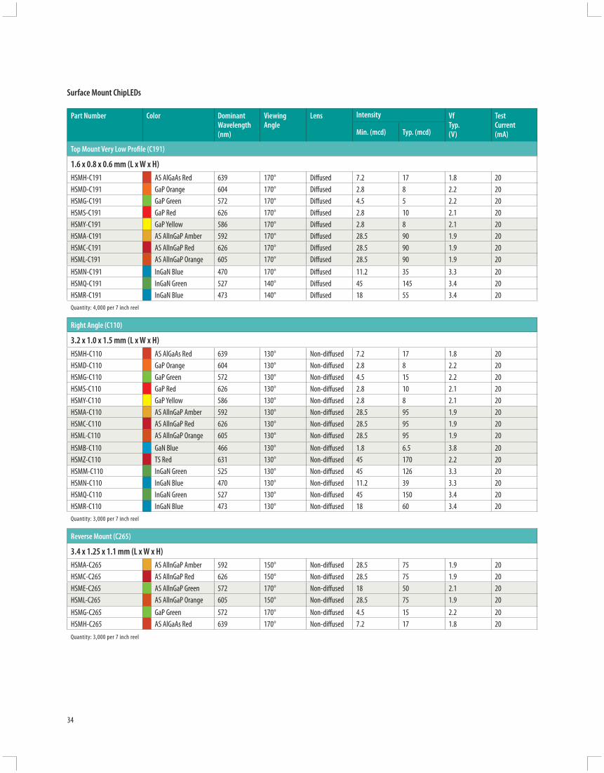
Top Mount Very Low Profi le (C191)
1.6 x 0.8 x 0.6 mm (L x W x H) HSMH-C191 AS AlGaAs Red 639 170° Diff used 7.2 17 1.8 20HSMD-C191 GaP Orange 604 170° Diff used 2.8 8 2.2 20HSMG-C191 GaP Green 572 170° Diff used 4.5 5 2.2 20HSMS-C191 GaP Red 626 170° Diff used 2.8 10 2.1 20HSMY-C191 GaP Yellow 586 170° Diff used 2.8 8 2.1 20HSMA-C191 AS AlInGaP Amber 592 170° Diff used 28.5 90 1.9 20HSMC-C191 AS AlInGaP Red 626 170° Diff used 28.5 90 1.9 20HSML-C191 AS AlInGaP Orange 605 170° Diff used 28.5 90 1.9 20HSMN-C191 InGaN Blue 470 170° Diff used 11.2 35 3.3 20HSMQ-C191 InGaN Green 527 140° Diff used 45 145 3.4 20HSMR-C191 InGaN Blue 473 140° Diff used 18 55 3.4 20Quantity: 4,000 per 7 inch reel
Right Angle (C110)
3.2 x 1.0 x 1.5 mm (L x W x H)HSMH-C110 AS AlGaAs Red 639 130° Non-diff used 7.2 17 1.8 20HSMD-C110 GaP Orange 604 130° Non-diff used 2.8 8 2.2 20HSMG-C110 GaP Green 572 130° Non-diff used 4.5 15 2.2 20HSMS-C110 GaP Red 626 130° Non-diff used 2.8 10 2.1 20HSMY-C110 GaP Yellow 586 130° Non-diff used 2.8 8 2.1 20HSMA-C110 AS AllnGaP Amber 592 130° Non-diff used 28.5 95 1.9 20HSMC-C110 AS AllnGaP Red 626 130° Non-diff used 28.5 95 1.9 20HSML-C110 AS AllnGaP Orange 605 130° Non-diff used 28.5 95 1.9 20HSMB-C110 GaN Blue 466 130° Non-diff used 1.8 6.5 3.8 20HSMZ-C110 TS Red 631 130° Non-diff used 45 170 2.2 20HSMM-C110 InGaN Green 525 130° Non-diff used 45 126 3.3 20HSMN-C110 InGaN Blue 470 130° Non-diff used 11.2 39 3.3 20HSMQ-C110 InGaN Green 527 130° Non-diff used 45 150 3.4 20HSMR-C110 InGaN Blue 473 130° Non-diff used 18 60 3.4 20Quantity: 3,000 per 7 inch reel
Reverse Mount (C265)
3.4 x 1.25 x 1.1 mm (L x W x H) HSMA-C265 AS AllnGaP Amber 592 150° Non-diff used 28.5 75 1.9 20HSMC-C265 AS AllnGaP Red 626 150° Non-diff used 28.5 75 1.9 20HSME-C265 AS AllnGaP Green 572 170° Non-diff used 18 50 2.1 20HSML-C265 AS AllnGaP Orange 605 150° Non-diff used 28.5 75 1.9 20HSMG-C265 GaP Green 572 170° Non-diff used 4.5 15 2.2 20HSMH-C265 AS AlGaAs Red 639 170° Non-diff used 7.2 17 1.8 20Quantity: 3,000 per 7 inch reel
Surface Mount ChipLEDs
35
Surfa
ce M
ount
ChipL
EDs
Part Number
Color Dominant Wavelength (nm)
Viewing Angle
Lens Intensity Vf Typ. (V)
Test Current (mA)Min. (mcd) Typ. (mcd)
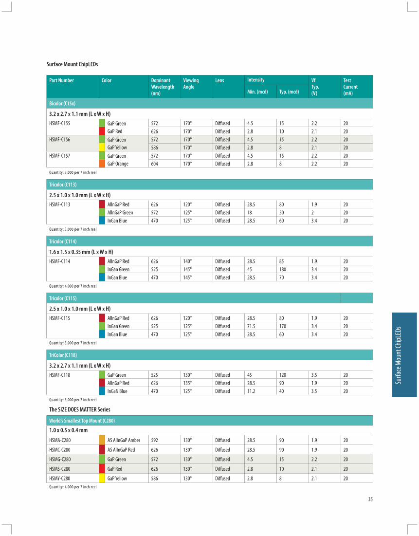
Bicolor (C15x)
3.2 x 2.7 x 1.1 mm (L x W x H)HSMF-C155 GaP Green
GaP Red572 170° Diff used 4.5 15 2.2 20626 170° Diff used 2.8 10 2.1 20
HSMF-C156 GaP GreenGaP Yellow
572 170° Diff used 4.5 15 2.2 20586 170° Diff used 2.8 8 2.1 20
HSMF-C157 GaP GreenGaP Orange
572 170° Diff used 4.5 15 2.2 20604 170° Diff used 2.8 8 2.2 20
Quantity: 3,000 per 7 inch reel
Tricolor (C113)
2.5 x 1.0 x 1.0 mm (L x W x H)HSMF-C113 AllnGaP Red 626 120° Diff used 28.5 80 1.9 20
AllnGaP Green 572 125° Diff used 18 50 2 20InGan Blue 470 125° Diff used 28.5 60 3.4 20
Quantity: 3,000 per 7 inch reel
Tricolor (C114)
1.6 x 1.5 x 0.35 mm (L x W x H)HSMF-C114 AllnGaP Red 626 140° Diff used 28.5 85 1.9 20
InGan Green 525 145° Diff used 45 180 3.4 20InGan Blue 470 145° Diff used 28.5 70 3.4 20
Quantity: 4,000 per 7 inch reel
Tricolor (C115)
2.5 x 1.0 x 1.0 mm (L x W x H)HSMF-C115 AllnGaP Red 626 120° Diff used 28.5 80 1.9 20
InGan Green 525 125° Diff used 71.5 170 3.4 20InGan Blue 470 125° Diff used 28.5 60 3.4 20
Quantity: 3,000 per 7 inch reel
TriColor (C118)
3.2 x 2.7 x 1.1 mm (L x W x H)HSMF-C118 GaP Green 525 130° Diff used 45 120 3.5 20
AllnGaP Red 626 135° Diff used 28.5 90 1.9 20InGaN Blue 470 125° Diff used 11.2 40 3.5 20
Quantity: 3,000 per 7 inch reel
The SIZE DOES MATTER Series
World’s Smallest Top Mount (C280)
1.0 x 0.5 x 0.4 mm
HSMA-C280 AS AlInGaP Amber 592 130° Diff used 28.5 90 1.9 20
HSMC-C280 AS AlInGaP Red 626 130° Diff used 28.5 90 1.9 20
HSMG-C280 GaP Green 572 130° Diff used 4.5 15 2.2 20
HSMS-C280 GaP Red 626 130° Diff used 2.8 10 2.1 20
HSMY-C280 GaP Yellow 586 130° Diff used 2.8 8 2.1 20Quantity: 4,000 per 7 inch reel
Surface Mount ChipLEDs

36
Part Number
Color Dominant Wavelength (nm)
Viewing Angle
Lens Intensity Vf Typ. (V)
Test Current (mA)Min. (mcd) Typ. (mcd)
Top Mount Very Low Profi le (C177)
2.0 x 1.25 x 0.4 mmHSMD-C177 GaP Orange 604 130° Diff used 2.8 8 2.2 20HSMG-C177 GaP Green 572 130° Diff used 4.5 5 2.2 20HSMS-C177 GaP Red 626 130° Diff used 2.8 10 2.1 20HSMA-C177 AS AlInGaP Amber 592 130° Diff used 28.5 90 1.9 20HSMC-C177 AS AlInGaP Red 626 130° Diff used 28.5 90 1.9 20HSML-C177 AS AlInGaP Orange 605 130° Diff used 28.5 90 1.9 20Quantity: 4,000 per 7 inch reel
Top Mount Very Low Profi le (C197)
1.6 x 0.8 x 0.4 mm (L x W x H)HSMD-C197 GaP Orange 604 130° Diff used 2.8 8 2.2 20HSMG-C197 GaP Green 572 130° Diff used 4.5 5 2.2 20HSMS-C197 GaP Red 626 130° Diff used 2.8 10 2.1 20HSMY-C197 GaP Yellow 586 130° Diff used 2.8 8 2.1 20HSMA-C197 AS AllnGaP Amber 592 130° Diff used 28.5 90 1.9 20HSMC-C197 AS AllnGaP Red 626 130° Diff used 28.5 90 1.9 20HSML-C197 AS AllnGaP Orange 605 130° Diff used 28.5 90 1.9 20Quantity: 4,000 per 7 inch reel
World’s Smallest Right Angle (C120)
1.6 x 0.6 x 1.0 mm (L x W x H)HSMH-C120 AS AlGaAs 639 155° Non-diff used 7.2 17 1.8 20HSMD-C120 GaP Orange 604 155° Non-diff used 2.8 8 2.2 20HSMG-C120 GaP Green 572 155° Non-diff used 4.5 15 2.2 20HSMA-C120 AS AllnGaP Amber 592 155° Non-diff used 28.5 90 1.9 20HSMC-C120 AS AllnGaP Red 626 155° Non-diff used 28.5 90 1.9 20HSML-C120 AS AllnGaP Orange 605 155° Non-diff used 28.5 90 1.9 20HSMM-C120 InGaN Green 525 155° Non-diff used 45 120 3.4 20HSMN-C120 InGaN Blue 470 155° Non-diff used 11.2 30 3.4 20HSMQ-C120 InGaN Green 527 155° Non-diff used 45 145 3.4 20HSMR-C120 InGaN Blue 473 155° Non-diff used 18 55 3.4 20Quantity: 4,000 per 7 inch reel
World’s Smallest Bicolor (C16x)
1.6 x 0.8 x 0.5 mmHSMF-C165 GaP Green
GaP Red572 120° Diff used 4.5 15 2.2 20626 120° Diff used 2.8 10 2.1 20
HSMF-C166 GaP GreenGaP Yellow
572 120° Diff used 4.5 15 2.2 20586 120° Diff used 2.8 8 2.1 20
HSMF-C167 GaP GreenGaP Orange
572 120° Diff used 4.5 15 2.2 20604 120° Diff used 2.8 8 2.2 20
Quantity: 4,000 per 7 inch reel
Surface Mount ChipLEDs

37
Surfa
ce M
ount
ChipL
EDs
Standard Intensity Categories
Bin ID Intensity (mcd)
Min. Max.
A 0.11 0.18
B 0.18 0.29
C 0.29 0.45
D 0.45 0.72
E 0.72 1.10
F 1.10 1.80
G 1.80 2.80
H 2.80 4.50
J 4.50 7.20
K 7.20 11.20
L 11.20 18.00
M 18.00 28.50
N 28.50 45.00
P 45.00 71.50
Q 71.50 112.50
R 112.50 180.00
S 180.00 285.00
T 285.00 450.00
U 450.00 715.00
V 715.00 1125.00
W 1125.00 1800.00
X 1800.00 2850.00
Y 2850.00 4500.00Tolerance: ±15%
Surface Mount ChipLEDs
Color Binnings
Package Color Bin
Wavelength (nm)
Min. Max.
GaN/InGaN Blue A 460.0 465.0
B 465.0 470.0
C 470.0 475.0
D 475.0 480.0
InGaN Green A 515.0 520.0
B 520.0 525.0
C 525.0 530.0
D 530.0 535.0
Orange A 597.0 600.0
B 600.0 603.0
C 603.0 606.0
D 606.0 609.0
E 609.0 612.0
F 612.0 615.0
Red Full Distribution
AlGaAs Red Full Distribution
Tolerance: ± 1.0 nm
Package Color Bin
Wavelength (nm)
Min. Max.
Green A 561.5 564.5
B 564.5 567.5
C 567.5 570.5
D 570.5 573.5
E 573.5 576.5
Yellow A 582.0 584.5
B 584.5 587.0
C 587.0 589.5
D 589.5 592.0
E 592.0 594.5
F 594.5 597.0
Amber A 582.0 584.5
B 584.5 587.0
C 587.0 589.5
D 589.5 592.0
E 592.0 594.5
F 594.5 597.0
Tolerance: ± 0.5 nm
0.5 (0.020)
1.5 (0.059)
CLEAREPOXY
PC BOARD
1.6 (0.063 )
3.2 (0.126 )
0.5 (0.020)
1.0 (0.039)
1.2 (0.047)CLEAREPOXY
PC BOARD
3.2 (0.126 )
CATHODEMARK
0.8 (0.031)
LED DIE
1.6 (0.063)
2.0 (0.079 )
CATHODEMARK
0.62 (0.024)
LED DIE
1.25 (0.049)
CATHODE MARK
LED DIE
1.25(0.049)
0.62(0.025)2.00 (0.079)
1.6(0.063 )
CATHODEMARK
0.4 (0.016)
LED DIE
0.8 (0.031)
0.80(0.031) 1.60
(0.063)
0.40(0.016)
CATHODE MARK
LED DIE3.4 (0.134) CATHODE
MARK (ETCHED)
1.25 (0.049)
LED DIE
GREEN SOLDER MASK 1.0 (0.04)
CATHODEMARK
0.25 (0.01)
LED DIE
0.5 (0.02)
3.2 (0.126 )
CATHODEMARK
1.4(0.055)
LED DIE
2.7(0.106)
1
3
2
4
1.6(0.063 )
LED DIES
0.8 (0.031)
CATHODE LINE
1
2
3
4
3.2 (0.126 )COMMONANODE
1.5(0.059)
LED DIE
2.7(0.106)
3 2
14
ANODEMARK
LED DIE
4
32
1
1.5(0.059)
1.6(0.063)
0.5 (0.020)
1.0 (0.039)
R 0.50 2.1 (0.082)
1.0 (0.039)
2.5 (0.098)
38
HSMx-C280
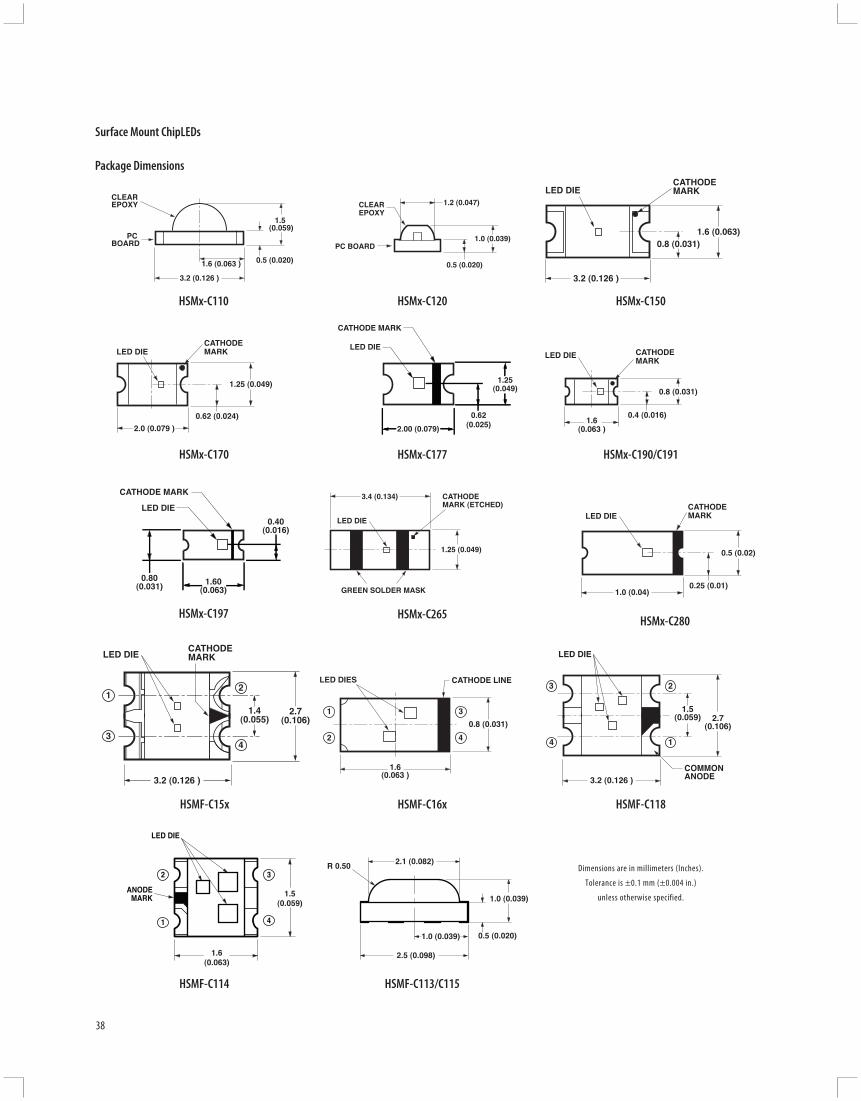
Package Dimensions
HSMx-C170
HSMx-C110
HSMx-C190/C191
HSMx-C150
HSMx-C177
Dimensions are in millimeters (Inches).
Tolerance is ±0.1 mm (±0.004 in.)
unless otherwise specified.
Surface Mount ChipLEDs
HSMF-C15x
HSMx-C197
HSMx-C120
HSMx-C265
HSMF-C16x HSMF-C118
HSMF-C114 HSMF-C113/C115

39
Auto
Focu
s Aux
iliary
Flas
h LED
Description
Avago Technologies ASMT-FJ10-ADH00 is a SMT (Surface Mount Technology) dome lamp that uses an untinted, non-diff used lens to provide a high luminous intensity within a narrow radiation pattern. The device is made by encapsulating LED chip on axial lead frame to form molded epoxy lamp package with 6 bended leads for surfacing mounting.
This lamp type LED utilizes Aluminum Indium Gallium Phosphate (AlInGaP) material technology. The AlInGaP material has a very high luminous effi ciency, capable of producing high light output over a wide range of drive currents. The color available for this SMT Lamp package is 612 nm Orange.
This narrow angle SMT lamp package is designed for applications that require long distance illumination and narrow beam pattern such as auxiliary fl ash for auto focus function in digital still camera etc. In order to facilitate pick and place operation, this SMT Lamp is shipped in tape and reel, with 1000 units per reel.
This package is compatible with Pb-free refl ow soldering process.
Auto Focus Auxiliary Flash LED
Eye Safety
These orange Surface Mount AF Lamps are used for camera application. The LEDs have lenses, which focus the beam at about 10 mm from the front of the lens, from where the beam diverges relatively slowly. If the LEDs were placed in a product, they would create a Class 1 LED to IEC/EN 60825-1 (2001) under all conditions of operation and single fault failure. As long as no collimating optics are added to the optical path.
Features and Benefi ts
• Smooth, consistent and narrow radiation pattern with 8° viewing angle
• Optimized viewing angle versus illumination distance
• Viewing angle is optimized for auto focus function, while not aff ecting the illumination distance required by digital still cameras (>3m)
• Small footprint with 4.8L x 4.8W x 5.33H mm package dimension
• Well-fi tted into compact digital still camera and mobile phone designs
• Allows easy assembly and PCB space saving
• Good Intensity Output • Up to 3m illumination• Compatible with refl ow soldering • IEC/EN 60825-1 Eye Safety Class 1
Target Market and Applications
• Consumer Electronics • Digital Still Camera • Camera Mobile Phone

1.27
0.51
0.15
4.80 ±0.1
5.33 ±0.1
NOTES:1. ALL DIMENSIONS IN MILLIMETERS.2. TOLERANCE IS ±0.1mm UNLESS OTHERWISE SPECIFIED.
PIN 1, 2, 4 - ANODEPIN 3, 5, 6 - CATHODE
3.92
5.20 ±0.1
4.80 ±0.1
1
2
3
4
5
6
4.32
40
Auto Focus Auxiliary Flash LEDPackage Dimensions
Part Number
Color Dominant Wavelength (nm)
Viewing Angle
Lens Intensity Vf Typ. (V)
Test Current (mA)Min. (mcd) Typ. (mcd)
ASMT-FJ10-ADH00 AlInGaP Orange 605 8° Clear 9 18 2 20
Iv Bin Category (cd)
Bin ID Min. Max.
D 9.0 11.5
E 11.5 15.0
F 15.0 19.5
G 19.5 25.5
H 25.5 33.0Iv Tolerance = ±15%
Color Bin CategoryOrange
Orange Min. (nm) Max. (nm)
A 600 604
B 604 608
C 608 612Tolerance = ±1 nm
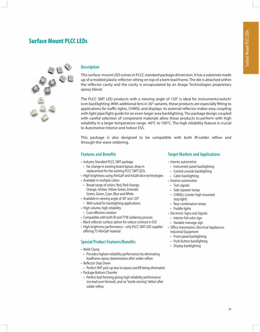
41
Surfa
ce M
ount
PLCC
LEDs
Description
This surface-mount LED comes in PLCC standard package dimension. It has a substrate made up of a molded plastic refl ector sitting on top of a bent lead frame. The die is attached within the refl ector cavity and the cavity is encapsulated by an Avago Technologies proprietary epoxy blend.
The PLCC SMT LED products with a viewing angle of 120° is ideal for instruments/switch/icon backlighting. With additional lens in 30° variants, these products are especially fi tting to applications for traffi c lights, CHMSL and displays. Its external refl ector makes easy coupling with light pipe/light guide for an even-larger area backlighting. The package design coupled with careful selection of component materials allow these products to perform with high reliability in a larger temperature range -40°C to 100°C. The high reliability feature is crucial to Automotive Interior and Indoor ESS.
This package is also designed to be compatible with both IR-solder refl ow and through-the-wave soldering.
Features and Benefi ts
• Industry Standard PLCC SMT package • No change in existing board layout, drop-in
replacement for the existing PLCC SMT LEDs• High brightness using AlInGaP and InGaN dice technologies• Available in multiple colors • Broad range of colors: Red, Red-Orange,
Orange, Amber, Yellow-Green, Emerald Green, Green, Cyan, Blue and White
• Available in viewing angle of 30° and 120° • Well-suited for backlighting applications• High volume, high reliability • Cost-eff ective solution• Compatible with both IR and TTW soldering process• Black refl ector surface option for reduce contrast in ESS• High brightness performance – only PLCC SMT LED supplier
off ering TS AlInGaP material
Special Product Features/Benefi ts
• Mold Clamp • Provides highest reliability performance by eliminating
leadframe-epoxy delamination after solder refl ow• Refl ector Step Down • Perfect SMT pick-up due to epoxy overfi ll being eliminated• Package Bottom Chamfer • Perfect lead forming giving high reliability performance
(no lead over-formed), and no “tomb-stoning” defect after solder refl ow
Surface Mount PLCC LEDs
Target Markets and Applications
• Interior automotive • Instrument panel backlighting • Central console backlighting • Cabin backlighting• Exterior automotive • Turn signals • Side repeater lamps • CHMSLs (center high-mounted
stop light) • Rear combination lamps • Puddle lights• Electronic Signs and Signals • Interior full color sign • Variable message sign• Offi ce Automation, Electrical Appliances,
Industrial Equipment • Front panel backlighting • Push button backlighting • Display backlighting

42
PLCC-2 Part Numbers and Typical Product Performance
Part Number
Color Dominant Wavelength λD (nm)
Viewing Angle2θ1/2 (°)
IV @ 20 mA VF @ 20 mA Typ. (V)Min. (mcd) Typ. (mcd)
HSMS-A100-L00J1 GaP Red 626 120 10 15 2.2HSMH-A100-N00J1 AlGaAs Red 637 120 25 50 1.9HSMC-A100-Q00J1 AlInGaP Red 626 120 63 100 1.9HSMC-A100-R00J1 AlInGaP Red 626 120 100 140 1.9HSMC-A101-S00J1 AlInGaP Red 626 120 160 220 1.9HSMZ-A100-T00J1 AlInGaP Red 630 120 250 350 2.2HSMJ-A100-Q00J1 AlInGaP Red Orange 615 120 63 100 1.9HSMJ-A101-S00J1 AlInGaP Red Orange 615 120 160 200 1.9HSMV-A100-T00J1 AlInGaP Red Orange 617 120 250 350 2.2HSMD-A100-L00J1 GaP Orange 602 120 10 15 2.2HSML-A100-Q00J1 AlInGaP Orange 605 120 63 100 1.9HSML-A101-S00J1 AlInGaP Orange 605 120 160 220 1.9HSMY-A100-L00J1 GaP Amber 585 120 10 12 2.2HSMA-A100-Q00J1 AlInGaP Amber 590 120 63 100 1.9HSMA-A101-S00J1 AlInGaP Amber 590 120 160 220 1.9HSMU-A100-S00J1 AlInGaP Amber 592 120 160 320 2.2HSMG-A100-J02J1 GaP Yellow Green 569 120 4 18 2.2HSME-A100-M02J1 AlInGaP Yellow Green 570 120 16 70 1.9HSMG-A100-H01J1 GaP Emerald Green 560 120 2.5 8 2.2HSME-A100-L01J1 AlInGaP Emerald Green 560 120 10 40 1.9HSMM-A101-R00J1 InGaN Green 525 120 100 200 3.4HSMM-A100-S00J1 InGaN Green 525 120 160 350 3.4HSMK-A101-R00J1 InGaN Cyan 505 120 100 170 3.4HSMK-A100-S00J1 InGaN Cyan 505 120 160 280 3.4HSMB-A100-J00J1 GaN Blue 462 120 4 15 3.9HSMN-A101-N00J1 InGaN Blue 470 120 25 50 3.4HSMN-A100-P00J1 InGaN Blue 470 120 40 70 3.4
Notes:1. The luminous intensity lV, is measured at the mechanical axis of the lamp package. The actual peak of the spatial radiation pattern may not be aligned with this axis.2. The dominant wavelength, λD, is derived from the CIE Chromaticity Diagram and represents the color of the device.3. θ1/2 is the off-axis angle where the luminous intensity is 1/2 the peak intensity.
PLCC Surface Mount LEDs
Device Selection Guide
Part Number Color Chromaticity Coordinates Viewing Angle IV @ 20 mA VF @ 20 mA
x y 2θ1/2 (°) Min. (mcd) Typ. (mcd) Typ. (V)
HSMW-A101-R50J1 InGaN White 0.31 0.31 120 100 – 3.4
HSMW-A100-T50J1 InGaN White 0.31 0.31 120 250 – 3.4
Notes:1. The luminous intensity IV, is measured at the mechanical axis of the lamp package. The actual peak of the spatial radiation pattern may not be aligned with this axis.2. The chromaticity coordinates are derived from the CIE 1931 Chromaticity Diagram and represents the perceived color of the device.3. θ1/2 is the off-axis angle where the luminous intensity is ½ the peak intensity.

43
Surfa
ce M
ount
PLCC
LEDs
Part Number Color 1 Color 2
Min. IV @ 20 mA Typ. IV @ 20 mA Min. IV @ 20 mA Typ. IV @ 20 mA
Bin ID (mcd) (mcd) Bin ID (mcd) (mcd)
HSMF-A21-A00J1 K2 8.0 16.0 L1 10.0 20.0
HSMF-A202-A00J1 K2 8.0 16.0 K1 6.3 12.0
HSMF-A203-A00J1 K2 8.0 16.0 J1 4.0 8.0
HSMF-A204-A00J1 K2 8.0 16.0 L1 10.0 20.0
HSMF-A205-A00J1 K2 8.0 16.0 J1 4.0 8.0
HSMF-A206-A00J1 K2 8.0 16.0 L1 10.0 20.0
HSMF-A211-A00J1 L2 12.5 25.0 L1 10.0 20.0
HSMF-A212-A00J1 L2 12.5 25.0 K1 6.3 12.0
HSMF-A222-A00J1 P1 40.0 80.0 P1 40.0 80.0
HSMF-A226-A00J1 P2 50.0 100.0 M2 20.0 60.0
HSMF-A227-A00J1 P1 40.0 80.0 J2 5.0 10.0
HSMF-A228-A00J1 P1 40.0 80.0 J2 5.0 10.0
Bicolor PLCC-4 Part Numbers and Typical Product Performance
Part Number Color 1 Color 2
HSMF-A201-xxxxx GaP Red GaP Yellow Green
HSMF-A202-xxxxx GaP Red GaP Yellow
HSMF-A203-xxxxx GaP Red GaP Emerald Green
HSMF-A204-xxxxx GaP Orange GaP Yellow Green
HSMF-A205-xxxxx GaP Orange GaP Emerald Green
HSMF-A206-xxxxx GaP Yellow GaP Yellow Green
HSMF-A211-xxxxx AlGaAs Red GaP Yellow Green
HSMF-A212-xxxxx AlGaAs Red GaP Yellow
HSMF-A222-xxxxx AlInGaP Red AlInGaP Amber
HSMF-A226-xxxxx AlInGaP Amber AlInGaP Yellow Green
HSMF-A227-xxxxx AlInGaP Red GaN Blue
HSMF-A228-xxxxx AlInGaP Amber GaN Blue
PLCC Surface Mount LEDs

44
Tricolor PLCC-4 Part Numbers and Typical Product Performance
Part Number Color 1 Color 2 Color 3
F-A301-xxxxx GaP Red GaP Yellow Green GaN Blue
HSMF-A331-xxxxx AlInGaP Red InGaN Green GaN Blue
HSMF-A332-xxxxx AlInGaP Red Orange InGaN Green GaN Blue
HSMF-A341-xxxxx AlInGaP Red InGaN Green InGaN Blue
HSMF-A342-xxxxx AlInGaP Red Orange InGaN Green InGaN Blue
Part Number Color 1 Color 2 Color 3
Min. IV @ 20 mA Typ. IV @ 20 mA
Min. IV @ 20 mA Typ. IV @ 20 mA
Min. IV @ 20 mA Typ. IV @ 20 mA
Bin ID (mcd) (mcd) Bin ID (mcd) (mcd) Bin ID (mcd) (mcd)
HSMF-A301-A00J1 K2 8.0 13.0 L2 12.5 20.0 K2 8.0 10.0
HSMF-A331-A00J1 P1 40.0 80.0 R1 100.0 160.0 K2 8.0 10.0
HSMF-A332-A00J1 P1 40.0 80.0 R1 100.0 160.0 K2 8.0 10.0
HSMF-A341-A00J1 P1 40.0 80.0 R1 100.0 160.0 N1 25.0 40.0
HSMF-A342-A00J1 P1 40.0 80.0 R1 100.0 160.0 N1 25.0 40.0
PLCC Surface Mount LEDs

45
Surfa
ce M
ount
PLCC
LEDs
Power PLCC-4 with Lens Part Numbers and Typical Product Performance
Part Number
Color Dominant WavelengthλD [1] (nm)
ViewingAngle 2θ1/2(°)
Min. IV (mcd)
Max. IV(mcd)
Typ. VF(V)
TestCurrent(mA)
HSMC-A130-W50M1 AlInGaP Red 626 30 1125 3550 2.2 50HSMC-A431-X90M1 AlInGaP Red 626 30 2240 7150 2.2 50HSMJ-A430-W50M1 AlInGaP Red Orange 615 30 1125 3550 2.2 50HSMJ-A431-X90M1 AlInGaP Red Orange 615 30 2240 7150 2.2 50HSMV-A430-Y90M1 AlInGaP Red Orange 617 30 3500 11250 2.8 50HSML-A431-X90M1 AlInGaP Orange 605 30 2240 7150 2.2 50HSMA-A430-W90M1 AlInGaP Amber 590 30 1400 4500 2.2 50HSMA-A431-Y00M1 AlInGaP Amber 590 30 2850 – 2.2 50HSMA-A431-X90M1 AlInGaP Amber 590 30 2240 7150 2.2 50HSMM-A430-W90M1 InGaN Green 525 30 1400 4500 3.9 30HSMN-A430-U50M2 InGaN Blue 470 30 450 1400 3.9 30HSMN-A431-T50M2 InGaN Blue 470 30 285 900 3.9 30
Notes:1. The luminous intensity, IV, is measured at the mechanical axis of the lamp package. The actual peak of the spatial radiation pattern may not be aligned with this axis.2. IV tolerance ±12%3. The dominant wavelength, lD, is derived from the CIE Chromaticity Diagram and represents the color of the device.4. θ1/2 is the off-axis angle where the luminous intensity is ½ the peak intensity.
Power PLCC-4 Part Numbers and Typical Product Performance
Part Number
Color Dominant WavelengthλD [1] (nm)
ViewingAngle 2θ1/2
[2]
(Degrees)
Min. IV (mcd)
Max. IV(mcd)
Typ. VF(V)
TestCurrent(mA)
HSMC-A400-S30M1 AlInGaP Red 626 120 160 395 2.2 50HSMC-A401-T40M1 AlInGaP Red 626 120 250 800 2.2 50HSMC-A401-T80M1 AlInGaP Red 626 120 310 1000 2.2 50HSMZ-A400-U80M1 AlInGaP Red 630 120 500 1600 2.8 50
HSMJ-A401-T40M1 AlInGaP Red Orange 615 120 250 800 2.2 50HSMJ-A401-U40M1 AlInGaP Red Orange 615 120 400 1260 2.2 50HSMV-A400-U80M1 AlInGaP Red Orange 617 120 500 1600 2.8 50HSML-A401-U40M1 AlInGaP Orange 605 120 400 1260 2.2 50HSMA-A400-T35M1 AlInGaP Amber 590 120 250 620 2.2 50HSMA-A401-U45M1 AlInGaP Amber 590 120 400 1260 2.2 50HSMU-A400-U85M1 AlInGaP Amber 592 120 500 1600 2.8 50HSME-A401-P4PM1 AlInGaP Emerald Green 567 120 40 130 2.2 50HSMM-A401-S4YM2 InGaN Green 525 120 160 500 3.8 30HSMM-A401-S7YM2 InGaN Green 525 120 200 500 3.8 30HSMM-A400-T8YM2 InGaN Green 525 120 310 1000 3.8 30HSMK-A401-R40M2 InGaN Cyan 505 120 100 315 3.8 30HSMK-A400-T80M2 InGaN Cyan 505 120 310 1000 3.8 30HSMN-A401-P4QM2 InGaN Blue 470 120 40 130 3.8 30HSMN-A401-P7QM2 InGaN Blue 470 120 50 130 3.8 30HSMN-A400-Q8QM2 InGaN Blue 470 120 80 250 3.8 30
Notes:1. The dominant wavelength, λD, is derived from the CIE Chromaticity Diagram and represents the color of the device.2. θ1/2 is the off-axis angle where the luminous intensity is 1/2 the peak intensity.3. The luminous intensity, IV, is measured at the mechanical axis of the lamp package. The actual peak of the spatial radiation pattern may not be aligned with this axis.
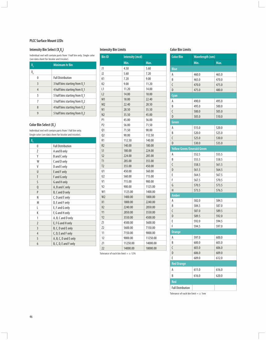
46
Intensity Bin Limits
Bin ID Intensity (mcd)
Min. Max.
J1 4.50 5.60J2 5.60 7.20K1 7.20 9.00K2 9.00 11.20L1 11.20 14.00L2 14.00 18.00M1 18.00 22.40M2 22.40 28.50N1 28.50 35.50N2 35.50 45.00P1 45.00 56.00P2 56.00 71.50Q1 71.50 90.00Q2 90.00 112.50R1 112.50 140.00R2 140.00 180.00S1 180.00 224.00S2 224.00 285.00T1 285.00 355.00T2 355.00 450.00U1 450.00 560.00U2 560.00 715.00V1 715.00 900.00V2 900.00 1125.00W1 1125.00 1400.00W2 1400.00 1800.00X1 1800.00 2240.00X2 2240.00 2850.00Y1 2850.00 3550.00Y2 3550.00 4500.00Z1 4500.00 5600.00Z2 5600.00 7150.0011 7150.00 9000.0012 9000.00 11250.0021 11250.00 14000.0022 14000.00 18000.00
Tolerance of each bin limit = ± 12%
Color Bin Limits
Color/Bin Wavelength (nm)
Min. Max.
Blue
A 460.0 465.0B 465.0 470.0C 470.0 475.0D 475.0 480.0
Cyan
A 490.0 495.0B 495.0 500.0C 500.0 505.0D 505.0 510.0
Green
A 515.0 520.0B 520.0 525.0C 525.0 530.0D 530.0 535.0
Yellow Green/Emerald Green
A 552.5 555.5B 555.5 558.5C 558.5 561.5D 561.5 564.5E 564.5 567.5F 567.5 570.5G 570.5 573.5H 573.5 576.5AmberA 582.0 584.5B 584.5 587.0C 587.0 589.5D 589.5 592.0E 592.0 594.5F 594.5 597.0
Orange
A 597.0 600.0B 600.0 603.0C 603.0 606.0D 606.0 609.0E 609.0 612.0
Red Orange
A 611.0 616.0
B 616.0 620.0
Red
Full DistributionTolerance of each bin limit = ± 1nm
Intensity Bin Select (X5X6)Individual reel will contain parts from 1 half bin only. Single color (see data sheet for bicolor and tricolor).
X5 Minimum Iv Bin
X6
0 Full Distribution
3 3 half bins starting from X51
4 4 half bins starting from X51
5 5 half bins starting from X51
7 3 half bins starting from X52
8 4 half bins starting from X52
9 5 half bins starting from X52
Color Bin Select (X7)Individual reel will contain parts from 1 full bin only. Single color (see data sheet for bi color and tricolor).
X7
0 Full DistributionZ A and B onlyY B and C onlyW C and D onlyV D and E onlyU E and F onlyT F and G onlyS G and H onlyQ A, B and C onlyP B, C and D onlyN C, D and E onlyM D, E and F onlyL E, F and G onlyK F, G and H only1 A, B, C and D only2 E, F G and H only3 B, C, D and E only 4 C, D, E and F only5 A, B, C, D and E only6 B, C, D, E and F only
PLCC Surface Mount LEDs

3.2 ±0.2
2.2 ±0.2
2.8 ±0.2
CATHODE MARKING(ANODE MARKING FOR AlGaAs DEVICES)
TOP MOUNT
0.8 ±0.1
0.5 ±0.1
0.1 TYP.
1.9 ±0.2
3.5 ±0.2
0.8 ±0.3
3.2 ±0.2
2.2 ±0.2
2.8 ±0.2
CATHODE MARKING
REVERSE MOUNT
0.5 ±0.1
0.1 TYP.
1.9 ±0.2
5.2 ±0.2
3.2 ±0.2
2.2 ±0.2
0.7 ±0.1-ve-ve
+ve -ve
2.8 ±0.2
PACKAGE MARKING
0.8 ±0.1
0.5 ±0.1
0.1 TYP.
3.87 MAX
3.5 ±0.2
0.8 ±0.3
-ve
3.2 ±0.2
2.2 ±0.2
0.7 ±0.1(1) (4)
(2) (3)
2.8 ±0.2
Cathode marking
0.8 ±0.1
0.5 ±0.1
0.1 typ.
1.9 ±0.2
3.5 ±0.2
0.8 ±0.3
47
Surfa
ce M
ount
PLCC
LEDs
Package Dimensions
Tricolor/Power PLCC-4
1 Cathode (Color 1)
2 Common Anode
3 Cathode (Color 3)
4 Cathode (Color 2)
Bicolor PLCC-4
1 Cathode (Color 1)
2 Anode (Color 1)
3 Cathode (Color 2)
4 Anode (Color 2)
Packaging Option (X8X9)
Option TestCurrent
PackageType
ReelSize
M1 50 mA Top Mount 7/13 Inch
M2 30 mA Top Mount 7/13 Inch
J1 20 mA Top Mount 7 Inch
J4 20 mA Top Mount 13 Inch
H1 20 mA Reverse Mount
7 Inch
H4 20 mA Reverse Mount
13 Inch
NOTE: ALL DIMENSIONS IN MILLIMETERS.
Single Color Top Mount
Single Color Reverse Mount
BiColor/TriColor PLCC4/Power PLCC-4

48
Subminiature Lamps
Description
Avago Technologies’ Subminiature Lamps are designed for modern printed circuit (PC) boards, replacing through-hole mounted components for many traditional functions with smaller components, sized for closer placement.
Subminiature Lamp components are available in several lead confi gurations that can be used for top mount or reverse mount, and through-hole applications. The lead confi gurations are ‘Gull Wing’–011 option, ‘Yoke Bend’–021 option and ‘Z Bend’–031 option. A variety of packages are available, such as fl at top, dome and rectangular in standard or low current options.
Features and Benefi ts
• Excellent product quality• Wide range of product off ering• Competitive pricing• Can be used with surface mount or through-hole
applications• High reliability • No replacement for life of equipment• Wide operating temperature range • Minor electrical/optical changes• Lower power consumption • High effi ciency, low drive currents
required, low driving voltages• Thin, light-weight and robust packaging • Excellent performance even under
vibration and mechanical shock• Diff erent thin material technologies available • Several colors available in GaP • Choice of colors (560 – 626 nm):
Green, Yellow, Amber, Orange, Red and Deep Red
• Three colors available in AlnGaP • Amber (590 nm), Red (626 nm) and
Orange (605 nm)• Two colors available in InGaN • Blue (472 nm), Green (526 nm) • Several lead confi guration options • Gull-wing, Yoke-bend and Z-bend• Several Packaging options • Diff erent sizes and spatial radiation
patterns available in bulk, right angle housing, and tape and reel
Typical Applications
• Industrial and Communication • Front panel and symbol indicator • Keypad and push button backlighting• Consumer • CD player, Hi-Fi audio and electrical
appliances • Keypad and push button backlighting• Automotive • Dashboard panel and symbol
backlighting • Car radio indicators
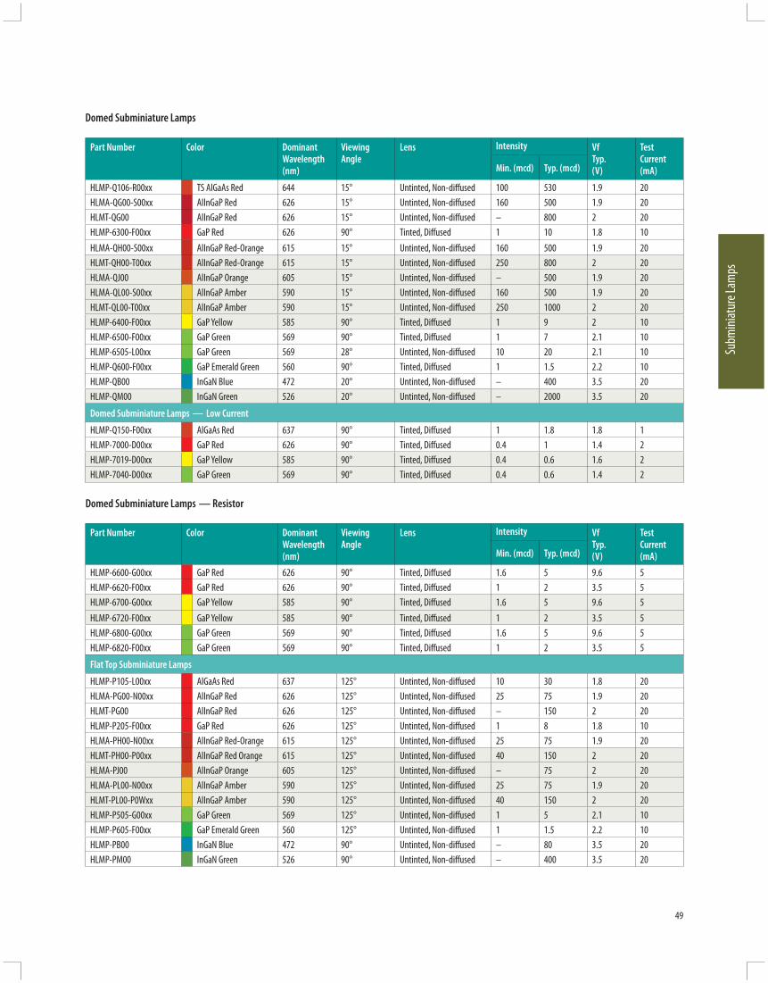
49
Subm
iniat
ure L
amps
Part Number
Color Dominant Wavelength (nm)
Viewing Angle
Lens Intensity Vf Typ. (V)
Test Current (mA)Min. (mcd) Typ. (mcd)
HLMP-Q106-R00xx TS AlGaAs Red 644 15° Untinted, Non-diff used 100 530 1.9 20HLMA-QG00-S00xx AlInGaP Red 626 15° Untinted, Non-diff used 160 500 1.9 20HLMT-QG00 AlInGaP Red 626 15° Untinted, Non-diff used – 800 2 20HLMP-6300-F00xx GaP Red 626 90° Tinted, Diff used 1 10 1.8 10HLMA-QH00-S00xx AlInGaP Red-Orange 615 15° Untinted, Non-diff used 160 500 1.9 20HLMT-QH00-T00xx AlInGaP Red-Orange 615 15° Untinted, Non-diff used 250 800 2 20HLMA-QJ00 AlInGaP Orange 605 15° Untinted, Non-diff used – 500 1.9 20HLMA-QL00-S00xx AlInGaP Amber 590 15° Untinted, Non-diff used 160 500 1.9 20HLMT-QL00-T00xx AlInGaP Amber 590 15° Untinted, Non-diff used 250 1000 2 20HLMP-6400-F00xx GaP Yellow 585 90° Tinted, Diff used 1 9 2 10HLMP-6500-F00xx GaP Green 569 90° Tinted, Diff used 1 7 2.1 10HLMP-6505-L00xx GaP Green 569 28° Untinted, Non-diff used 10 20 2.1 10HLMP-Q600-F00xx GaP Emerald Green 560 90° Tinted, Diff used 1 1.5 2.2 10HLMP-QB00 InGaN Blue 472 20° Untinted, Non-diff used – 400 3.5 20HLMP-QM00 InGaN Green 526 20° Untinted, Non-diff used – 2000 3.5 20
Domed Subminiature Lamps — Low Current
HLMP-Q150-F00xx AlGaAs Red 637 90° Tinted, Diff used 1 1.8 1.8 1HLMP-7000-D00xx GaP Red 626 90° Tinted, Diff used 0.4 1 1.4 2HLMP-7019-D00xx GaP Yellow 585 90° Tinted, Diff used 0.4 0.6 1.6 2HLMP-7040-D00xx GaP Green 569 90° Tinted, Diff used 0.4 0.6 1.4 2
Domed Subminiature Lamps — Resistor
Part Number
Color Dominant Wavelength (nm)
Viewing Angle
Lens Intensity Vf Typ. (V)
Test Current (mA)Min. (mcd) Typ. (mcd)
HLMP-6600-G00xx GaP Red 626 90° Tinted, Diff used 1.6 5 9.6 5HLMP-6620-F00xx GaP Red 626 90° Tinted, Diff used 1 2 3.5 5HLMP-6700-G00xx GaP Yellow 585 90° Tinted, Diff used 1.6 5 9.6 5HLMP-6720-F00xx GaP Yellow 585 90° Tinted, Diff used 1 2 3.5 5HLMP-6800-G00xx GaP Green 569 90° Tinted, Diff used 1.6 5 9.6 5HLMP-6820-F00xx GaP Green 569 90° Tinted, Diff used 1 2 3.5 5
Flat Top Subminiature Lamps
HLMP-P105-L00xx AlGaAs Red 637 125° Untinted, Non-diff used 10 30 1.8 20HLMA-PG00-N00xx AlInGaP Red 626 125° Untinted, Non-diff used 25 75 1.9 20HLMT-PG00 AlInGaP Red 626 125° Untinted, Non-diff used – 150 2 20HLMP-P205-F00xx GaP Red 626 125° Untinted, Non-diff used 1 8 1.8 10HLMA-PH00-N00xx AlInGaP Red-Orange 615 125° Untinted, Non-diff used 25 75 1.9 20HLMT-PH00-P00xx AlInGaP Red Orange 615 125° Untinted, Non-diff used 40 150 2 20HLMA-PJ00 AlInGaP Orange 605 125° Untinted, Non-diff used – 75 2 20HLMA-PL00-N00xx AlInGaP Amber 590 125° Untinted, Non-diff used 25 75 1.9 20HLMT-PL00-P0Wxx AlInGaP Amber 590 125° Untinted, Non-diff used 40 150 2 20HLMP-P505-G00xx GaP Green 569 125° Untinted, Non-diff used 1 5 2.1 10HLMP-P605-F00xx GaP Emerald Green 560 125° Untinted, Non-diff used 1 1.5 2.2 10HLMP-PB00 InGaN Blue 472 90° Untinted, Non-diff used – 80 3.5 20HLMP-PM00 InGaN Green 526 90° Untinted, Non-diff used – 400 3.5 20
Domed Subminiature Lamps

50
Subminiature Lamps are also available in the following options:
Mechanical Option Number
Description
10 Right Angle11 Tape and Reel, 1500 lamps per reel12 Gull Wing, Bulk Packaging21 Yoke Lead, Tape and Reel, 1500 lamps per reel22 Yoke Lead, Bulk Packaging31 Z-Bend, Tape and Reel, 1500 lamps per reel32 Z-Bend, Bulk Packaging
Surface Mount Subminiature LED LampsStandard Intensity Categories
Package Universal Customer Iv in mcd
Bin Min. Max.
A 0.1 0.2B 0.16 0.32C 0.25 0.5D 0.4 0.8E 0.63 1.25F 1 2G 1.6 3.2H 2.5 5J 4 8K 6.3 12.5L 10 20M 16 32N 25 50P 40 80Q 63 125R 100 200S 160 320T 250 500U 400 800V 630 1250W 1000 2000X 1600 3200Y 2500 5000
Package Universal ColorBin
Wavelength (nm)
Min. Max.
InGaN Blue 0 Full dist.1 460 4642 464 4683 468 4724 472 4765 476 4806 480 484
InGaN Green 0 Full dist.1 520 5302 530 540
Emerald Green 9 552 5568 555 5597 558 5626 561 565
Green 5 565 5684 567 5713 570 5742 573 577
Yellow 1 581.5 5853 584 587.52 586.5 5904 589 592.55 591.5 593.56 591.5 5957 594 597.5
Orange 1 596.5 6002 599 602.53 601.5 6044 603.8 608.25 606.8 611.26 609.8 614.27 612.8 617.28 615.8 620.2
Red Orange 1 617.5 6252 621 628.53 624.5 632
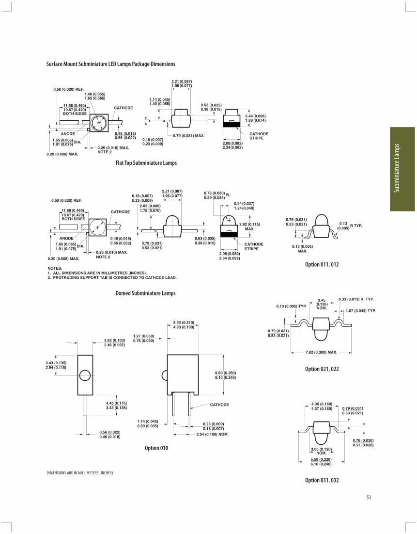
0.460.56
(0.018)(0.022)
1.401.65
(0.055)(0.065)
0.25 (0.010) MAX.NOTE 2 0.20 (0.008) MAX.
0.50 (0.020) REF.
CATHODE
1.651.91
(0.065)(0.075)DIA.
ANODE
11.6810.67
(0.460)(0.420)
BOTH SIDES
1.141.40
(0.045)(0.055) 0.63
0.38(0.025)(0.015)
2.211.96
(0.087)(0.077)
0.180.23
(0.007)(0.009)
2.441.88
(0.096)(0.074)
2.082.34
(0.082)(0.092)
CATHODESTRIPE
0.79 (0.031) MAX.
NOTES:1. ALL DIMENSIONS ARE IN MILLIMETRES (INCHES).2. PROTRUDING SUPPORT TAB IS CONNECTED TO CATHODE LEAD.
0.50 (0.020) REF.0.941.24
(0.037)(0.049)
2.92 (0.115)MAX.
0.760.89
(0.030)(0.035)
R.
0.630.38
(0.025)(0.015)
2.03 (0.080)1.78 (0.070)
0.79 (0.031)0.53 (0.021)
0.460.56
(0.018)(0.022)
0.25 (0.010) MAX.NOTE 2 0.20 (0.008) MAX.
CATHODE
1.651.91
(0.065)(0.075)
DIA.
ANODE
11.6810.67
(0.460)(0.420)
BOTH SIDES
0.180.23
(0.007)(0.009)
2.082.34
(0.082)(0.092)
CATHODESTRIPE
2.211.96
(0.087)(0.077)
0.13(0.005)
0.13 (0.005)MAX.
0.79 (0.031)0.53 (0.021) R TYP.
7.62 (0.300) MAX.
0.79 (0.031)0.53 (0.021)
0.13 (0.005) TYP.
0.33 (0.013) R. TYP.3.45(0.136)NOM.
1.07 (0.042) TYP.
0.79 (0.031)0.53 (0.021)
4.06 (0.160)4.57 (0.180)
0.76 (0.030)0.51 (0.020)
5.59 (0.220)6.10 (0.240)
3.05 (0.120)NOM.
4.45 (0.175)3.43 (0.136)
2.62 (0.103)2.46 (0.097)
5.33 (0.210)4.83 (0.190)
1.27 (0.050)0.76 (0.030)
6.60 (0.260)6.10 (0.240)
1.14 (0.045)0.89 (0.035) 0.23 (0.009)
0.18 (0.007)2.54 (0.100) NOM.
3.43 (0.135)2.94 (0.115)
0.56 (0.022)0.46 (0.018)
CATHODE
51
Subm
iniat
ure L
amps
Surface Mount Subminiature LED Lamps Package Dimensions
Flat Top Subminiature Lamps
Domed Subminiature Lamps
Option 010
Option 011, 012
Option 021, 022
Option 031, 032DIMENSIONS ARE IN MILLIMETERS (INCHES)

52
Seven-Segment DisplaysDescription
Avago Technologies off ers a full range of seven-segment displays from low cost, standard brightness displays to high ambient light displays that produce up to 7.5mcd per segment. Dual and single digit displays are available in assorted character heights and colors. They are divided into two platforms to address diff erent market requirements in both industrial and consumer markets. Displays for industrial markets are designed for high-reliability applications and feature extremely durable packaging for high temperature environments. Consumer applications are designed for cost-sensitive, general-purpose display applications.
Product Features and Benefi ts
• Semiconductor (LED) light source • Cost-eff ective solutions • Flexibility for designers • Light weight• Lower power consumption • Electrical power savings • Low heat generation • Low current devices available
Industrial Applications: High Performance Seven-segment Display Package
Industrial grade products provide high peak current, automated IV/color bining and the availability of intensity and color selection. Ideal for high reliability applications such as temperature controllers, this package is extremely durable in high temperature environments with better heat dissipation through a mild steel leadframe.
Key benefi ts for the leadframe platform
• Heat dissipation from the package is faster than other PCB display products• Brightness (Iv) degradation reduced over time• Lead stability and consistency• Solder coated leads result in better solderability• Typical epoxy Tg is 140°C resulting in improved temperature cycling reliability
• Mechanically rugged • No wire fi laments • No moving parts • Not sensitive to
mechanical shock and vibration
• Essentially monochromatic light • No color fi lter required • Maximum use of visible light
• Easy for the eye to discern against distracting backgrounds in sunlight and adverse weather conditions
• High light output• Industry standard size and pinout• Categorized for luminous intensity
(yellow and green categorized for color)
Consumer Applications: Standard Seven-segment Display Package
Designed for the cost-competitive general purpose commercial LED display applications, this package is built with a PCB substrate using ultrasonic stitch to stitch bonding with aluminum wire.
Key benefi ts for the PCB platform
• Competitive prices• Avago Technologies quality, reliability
and technical support• Typical epoxy Tg is 100–120°C,
suitable for applications that do not experience extreme temperatures and temperature cycling
Avago Technologies is committed to support the market by off ering display performance and features that are specifi c to the designer’s application requirements.
Typical Industrial Applications
High Performance Seven-segment Displays:• Temperature controllers• Test and measurement
instrumentation• Power converters• Home appliance displays• Automotive and avionics
instrumentation• Fuel pump displays• Digital panel meters Typical Consumer Applications
Standard Seven-segment Displays:• Cable set-top boxes• Electronics displays• Gaming machines• Point of sale terminals• Answering machines• Exercise equipment

53
Seve
n-Se
gmen
t Disp
lays
Part Number Face Color Pin Confi guration Intensity (µcd) Iv Test Current (mA)
Vf Typ. (V) Vf TestCurrent (mA)
Decimal
Min. Typ.
14.2 mm (0.56”) Single Digit Displays
Blue 466 nm
HDSP-501B Grey Common Anode 2020 3400 10 3.8 20 Right
HDSP-503B Grey Common Cathode 2020 3400 10 3.8 20 Right
14.2 mm (0.56”) Dual Digit Displays
GaP Yellow 587 nm
HDSP-521Y Grey Common Anode 680 1800 10 2.1 20 Right
HDSP-523Y Grey Common Cathode 680 1800 10 2.1 20 Right
GaP Red 626 nm
HDSP-521E Grey Common Anode 1010 2800 10 2.1 20 Right
HDSP-523E Grey Common Cathode 1010 2800 10 2.1 20 Right
GaP Green 571 nm HDSP-521G Grey Common Anode 1010 2500 10 2.1 10 Right
HDSP-523G Grey Common Cathode 1010 2500 10 2.1 10 Right
AlGaAs Red 643 nm HDSP-521A Grey Common Anode 3201 6500 10 1.85 20 Right
HDSP-523A Grey Common Cathode 3201 6500 10 1.85 20 Right
20 mm (0.8”) Single Digit Displays
GaP Red 626 nm
HDSP-815E Grey Common Anode 2300 4800 20 2.1 20 Right
HDSP-816E Grey Common Cathode 2300 4800 20 2.1 20 Right
GaP Green 571 nm
HDSP-815G Grey Common Anode 1500 3300 20 2.1 20 Right
HDSP-816G Grey Common Cathode 1500 3300 20 2.1 20 Right
10 mm (0.4”) Slim Font Single Digit Display
GaP Red 625 nm
HDSP-301E Grey Common Anode 1251 2000 10 1.90 20 Right
HDSP-303E Grey Common Cathode 1251 2000 10 1.90 20 Right
GaP Green 573 nm
HDSP-301G Grey Common Anode 2001 3200 10 2.25 20 Right
HDSP-303G Grey Common Cathode 2001 3200 10 2.25 20 Right
AlGaAs Red 643 nm
HDSP-301A Grey Common Anode 320 505 1 1.80 20 Right
HDSP-303A Grey Common Cathode 320 505 1 1.80 20 Right
GaP Yellow 590 nm
HDSP-301Y Grey Common Anode 1251 2000 10 2.15 20 Right
HDSP-303Y Grey Common Cathode 1251 2000 10 2.15 20 Right
Standard Seven-Segment Displays

54
Part Number Face Color Pin Confi guration Intensity (µcd) Iv Test Current (mA)
Vf Typ. (V) Vf TestCurrent (mA)
Decimal
Min. Typ.
13 mm (0.56”) Slim Font Single Digit Display
GaP Red 625 nm
HDSP-561E Grey Common Anode 2001 3526 10 1.90 20 Right
HDSP-563E Grey Common Cathode 2001 3526 10 1.90 20 Right
GaP Green 573 nm
HDSP-561G Grey Common Anode 3201 5601 10 2.25 20 Right
HDSP-563G Grey Common Cathode 3201 5601 10 2.25 20 Right
AlGaAs Red 643 nm
HDSP-521E Grey Common Anode 1010 2800 10 2.1 20 Right
HDSP-523E Grey Common Cathode 1010 2800 10 2.1 20 Right
GaP Yellow 590 nm
HDSP-561A Grey Common Anode 506 878 1 1.80 20 Right
HDSP-563A Grey Common Cathode 506 878 1 1.80 20 Right
7.62 mm (0.3”) Single Digit Display
GaP Red 620 nm
HDSP-331E Grey Common Anode 800 1800 10 2.05 20 Right & Left
HDSP-333E Grey Common Cathode 800 1800 10 2.05 20 Right
HDSP-334E Grey Common Cathode 800 1800 10 2.05 20 Right
GaP Green 573 nm
HDSP-331G Grey Common Anode 800 2000 10 2.25 20 Right & Left
HDSP-333G Grey Common Cathode 800 2000 10 2.25 20 Right
HDSP-334G Grey Common Cathode 800 2000 10 2.25 20 Right
AlGaAs Red 643 nm
HDSP-331A Grey Common Anode 2001 4200 10 1.85 20 Right & Left
HDSP-333A Grey Common Cathode 2001 4200 10 1.85 20 Right
HDSP-334A Grey Common Cathode 2001 4200 10 1.85 20 Right
GaP Yellow 590 nm
HDSP-331Y Grey Common Anode 800 1500 10 2.15 20 Right & Left
HDSP-333Y Grey Common Cathode 800 1500 10 2.15 20 Right
HDSP-334Y Grey Common Cathode 800 1500 10 2.15 20 Right
Standard Seven-Segment Displays

55
Seve
n-Se
gmen
t Disp
lays
Part Number Face Color Pin Confi guration Intensity (µcd) Iv Test Current (mA)
Vf Typ. (V) Vf TestCurrent (mA)
Decimal
Min. Typ.
10.16 mm (0.4”S) Single Digit Display
GaP Red 620 nm
HDSP-311E Grey Common Anode 1250 3200 10 2.05 20 Right
HDSP-313E Grey Common Cathode 1250 3200 10 2.05 20 Right
GaP Green 573 nm
HDSP-311G Grey Common Anode 1250 3200 10 2.25 20 Right
HDSP-313G Grey Common Cathode 1250 3200 10 2.25 20 Right
AlGaAs Red 643 nm
HDSP-311A Grey Common Anode 3200 7500 10 1.85 20 Right
HDSP-313A Grey Common Cathode 3200 7500 10 1.85 20 Right
GaP Yellow 590 nm
HDSP-311Y Grey Common Anode 800 1500 10 2.15 20 Right
HDSP-313Y Grey Common Cathode 800 1500 10 2.15 20 Right
10.16 mm (0.4”D) Dual Digit Display
GaP Red 620 nm
HDSP-G01E Grey Common Anode 1250 2600 10 2.05 20 –
HDSP-G03E Grey Common Cathode 1250 2600 10 2.05 20 –
GaP Green 573 nm
HDSP-G01G Grey Common Anode 1250 3200 10 2.25 20 –
HDSP-G03G Grey Common Cathode 1250 3200 10 2.25 20 –
AlGaAs Red 643nm
HDSP-G01A Grey Common Anode 3200 6500 10 1.85 20 –
HDSP-G03A Grey Common Cathode 3200 6500 10 1.85 20 –
GaP Yellow 590 nm
HDSP-G01Y Grey Common Anode 800 1500 10 2.15 20 –
HDSP-G03Y Grey Common Cathode 800 1500 10 2.15 20 –
Standard Seven-Segment Displays

56
Part Number Face Color Pin Confi guration Intensity (µcd) Iv Test Current (mA)
Vf Typ. (V) Vf TestCurrent (mA)
Decimal
Min. Typ.
14.22 mm (0.56”S) Single Digit Display
GaP Red 620 nm
HDSP-511E Grey Common Anode 2001 4100 10 2.05 20 Right
HDSP-513E Grey Common Cathode 2001 4100 10 2.05 20 Right
GaP Green 573 nm
HDSP-511G Grey Common Anode 2001 4100 10 2.25 20 Right
HDSP-513G Grey Common Cathode 2001 4100 10 2.25 20 Right
AlGaAs Red 643 nm
HDSP-511A Grey Common Anode 3201 6500 10 1.85 20 Right
HDSP-513A Grey Common Cathode 3201 6500 10 1.85 20 Right
GaP Yellow 590 nm
HDSP-511Y Grey Common Anode 1251 2600 10 2.15 20 Right
HDSP-513Y Grey Common Cathode 1251 2600 10 2.15 20 Right
Standard Seven-Segment Displays
LED Standard Displays — Seven-Segment DisplaysLuminous Intensity Categories (Typ.)
0.56 ” Dual DigitBin ID Customer lv in mcd
Min. Max.
GaP Red HDSP-52xEG 2.28 3.42
H 3.42 5.13
I 5.13 7.69
GaP Yellow HDSP-52xYF 1.52 2.28
G 2.28 3.42
H 3.42 5.13
GaP Green HDSP-52xGG 2.28 3.42
H 3.42 5.13
AlGaAs Red HDSP-52xAJ 3.201 5.050
K 5.051 8.000
L 8.001 12.650
0.56 ” Single DigitBin ID Customer lv in mcd
Min. Max.
Blue HDSP-50xBH 2.02 2.63
I 2.63 3.42
J 3.42 4.20
K 4.20 5.04
0.8 ” Single DigitBin ID Customer lv in mcd
Min. Max.
GaP Red HDSP-81xEN 4.78 8.34
P 6.82 11.86
Q 9.7 16.61
GaP Green HDSP-81xGP 6.82 11.86
Q 9.7 16.61
R 13.6 23.74

57
Seve
n-Se
gmen
t Disp
lays
LED Standard Displays — Seven-Segment DisplaysLuminous Intensity Categories (Typ.)
10 mm (0.4”) Slim Font Single DigitBin ID Customer lv in mcd
Min. Max.
GaP Red HDSP-30xEI 1.100 2.200K 1.800 3.600
GaP Green HDSP-30xGK 1.800 3.600L 2.800 5.600
AlGaAs Red HDSP-30xAF 0.280 0.560G 0.450 0.900
GaP Yellow HDSP-30xYI 1.100 2.200K 1.800 3.600
7.62 mm (0.3”) Single DigitBin ID Customer lv in mcd
Min. Max.
GaP Red HDSP-33xEG 0.801 1.250H 1.251 2.000I 2.001 3.200
GaP Green HDSP-33xGG 0.801 1.250H 1.251 2.000I 2.001 3.200
AlGaAs Red HDSP-33xAI 2.001 3.200J 3.201 5.050K 5.051 8.000
GaP Yellow HDSP-33xYG 0.801 1.250H 1.251 2.000I 2.001 3.200
Standard Seven-Segment Displays
13 mm (0.56”) Slim Font Single DigitBin ID Customer lv in mcd
Min. Max.
GaP Red HDSP-56xEI 1.100 2.200K 1.800 3.600
GaP Green HDSP-56xGK 1.800 3.600L 2.800 5.600
AlGaAs Red HDSP-56xAF 0.280 0.560G 0.450 0.900
GaP Yellow HDSP-56xYI 1.100 2.200K 1.800 3.600
10.16 mm (0.4”) Single DigitBin ID Customer lv in mcd
Min. Max.
GaP Red HDSP-31xEH 1.251 2.000I 2.001 3.200J 3.201 5.050
GaP Green HDSP-31xGH 1.251 2.000I 2.001 3.200J 3.201 5.050
AlGaAs Red HDSP-31xAJ 3.201 5.050K 5.051 8.000L 8.001 12.650
GaP Yellow HDSP-31xYG 0.801 1.250H 1.251 2.000I 2.001 3.200
10.16 mm (0.4”D) Dual DigitBin ID Customer lv in mcd
Min. Max.
GaP Red HDSP-G0xEH 1.251 2.000I 2.001 3.200J 3.201 5.050
GaP Green HDSP-G0xGH 1.251 2.000I 2.001 3.200J 3.201 5.050
AlGaAs Red HDSP-G0xAJ 3.201 5.050K 5.051 8.000L 8.001 12.650
GaP Yellow HDSP-G0xYG 0.801 1.250H 1.251 2.000I 2.001 3.200
14.22 mm (0.56”) Single DigitBin ID Customer lv in mcd
Min. Max.
GaP Red HDSP-51xEI 2.001 3.200J 3.201 5.050K 5.051 8.000
GaP Green HDSP-51xGI 2.001 3.200J 3.201 5.050K 5.051 8.000
AlGaAs Red HDSP-51xAJ 3.201 5.050K 5.051 8.000L 8.001 12.650
GaP Yellow HDSP-51xYH 1.251 2.000I 2.001 3.200J 3.201 5.050
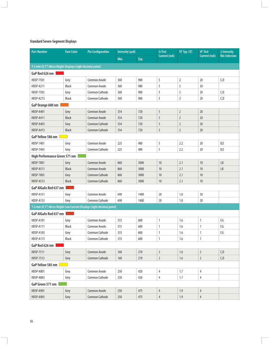
58
Part Number Face Color Pin Confi guration Intensity (µcd) Iv Test Current (mA)
Vf Typ. (V) Vf TestCurrent (mA)
2 IntensityBin Selection
Min. Typ.
7.6 mm (0.3”) Micro Bright Displays (right decimal point)
GaP Red 626 nm
HDSP-7501 Grey Common Anode 360 980 5 2 20 C,D
HDSP-A211 Black Common Anode 360 980 5 2 20
HDSP-7503 Grey Common Cathode 360 980 5 2 20 C,D
HDSP-A213 Black Common Cathode 360 980 5 2 20 C,D
GaP Orange 600 nm
HDSP-A401 Grey Common Anode 354 720 5 2 20
HDSP-A411 Black Common Anode 354 720 5 2 20
HDSP-A403 Grey Common Cathode 354 720 5 2 20
HDSP-A413 Black Common Cathode 354 720 5 2 20
GaP Yellow 586 nm
HDSP-7401 Grey Common Anode 225 480 5 2.2 20 D,E
HDSP-7403 Grey Common Cathode 225 480 5 2.2 20 D,E
High Performance Green 571 nm
HDSP-7801 Grey Common Anode 860 3000 10 2.1 10 J,K
HDSP-A511 Black Common Anode 860 3000 10 2.1 10 J,K
HDSP-7803 Grey Common Cathode 860 3000 10 2.1 10
HDSP-A513 Black Common Cathode 860 3000 10 2.1 10
GaP AlGaAs Red 637 nm
HDSP-A151 Grey Common Anode 690 1400 20 1.8 20
HDSP-A153 Grey Common Cathode 690 1400 20 1.8 20
7.6 mm (0.3”) Micro Bright Low Current Displays (right decimal point)
GaP AlGaAs Red 637 nm
HDSP-A101 Grey Common Anode 315 600 1 1.6 1 F,G
HDSP-A111 Black Common Anode 315 600 1 1.6 1 F,G
HDSP-A103 Grey Common Cathode 315 600 1 1.6 1 F,G
HDSP-A113 Black Common Cathode 315 600 1 1.6 1
GaP Red 626 nm
HDSP-7511 Grey Common Anode 160 270 2 1.6 2 C,D
HDSP-7513 Grey Common Cathode 160 270 2 1.6 2 C,D
GaP Yellow 585 nm
HDSP-A801 Grey Common Anode 250 420 4 1.7 4
HDSP-A803 Grey Common Cathode 250 420 4 1.7 4
GaP Green 571 nm
HDSP-A901 Grey Common Anode 250 475 4 1.9 4
HDSP-A903 Grey Common Cathode 250 475 4 1.9 4
Standard Seven-Segment Displays
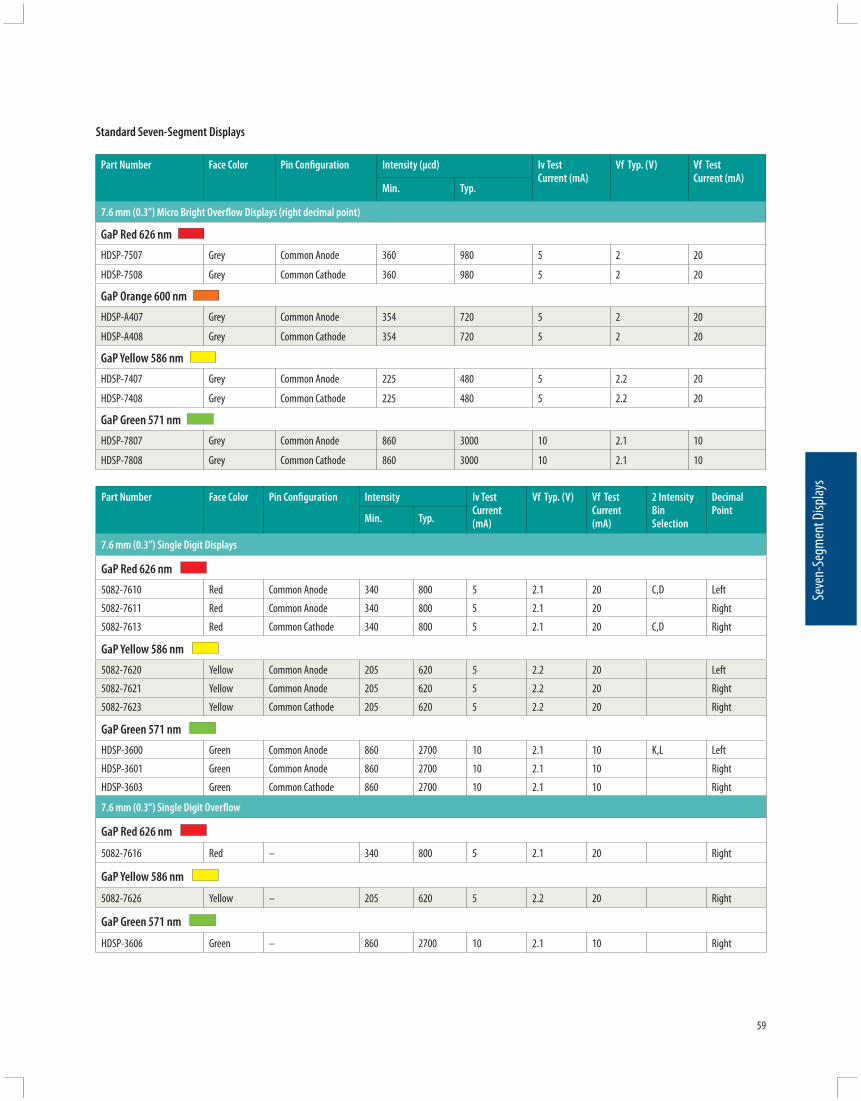
59
Seve
n-Se
gmen
t Disp
lays
Part Number Face Color Pin Confi guration Intensity (µcd) Iv Test Current (mA)
Vf Typ. (V) Vf TestCurrent (mA)
Min. Typ.
7.6 mm (0.3”) Micro Bright Overfl ow Displays (right decimal point)
GaP Red 626 nm
HDSP-7507 Grey Common Anode 360 980 5 2 20
HDSP-7508 Grey Common Cathode 360 980 5 2 20
GaP Orange 600 nm
HDSP-A407 Grey Common Anode 354 720 5 2 20
HDSP-A408 Grey Common Cathode 354 720 5 2 20
GaP Yellow 586 nm
HDSP-7407 Grey Common Anode 225 480 5 2.2 20
HDSP-7408 Grey Common Cathode 225 480 5 2.2 20
GaP Green 571 nm
HDSP-7807 Grey Common Anode 860 3000 10 2.1 10
HDSP-7808 Grey Common Cathode 860 3000 10 2.1 10
Standard Seven-Segment Displays
Part Number Face Color Pin Confi guration Intensity Iv Test Current (mA)
Vf Typ. (V) Vf TestCurrent (mA)
2 Intensity Bin Selection
Decimal Point
Min. Typ.
7.6 mm (0.3”) Single Digit Displays
GaP Red 626 nm
5082-7610 Red Common Anode 340 800 5 2.1 20 C,D Left
5082-7611 Red Common Anode 340 800 5 2.1 20 Right
5082-7613 Red Common Cathode 340 800 5 2.1 20 C,D Right
GaP Yellow 586 nm
5082-7620 Yellow Common Anode 205 620 5 2.2 20 Left
5082-7621 Yellow Common Anode 205 620 5 2.2 20 Right
5082-7623 Yellow Common Cathode 205 620 5 2.2 20 Right
GaP Green 571 nm
HDSP-3600 Green Common Anode 860 2700 10 2.1 10 K,L Left
HDSP-3601 Green Common Anode 860 2700 10 2.1 10 Right
HDSP-3603 Green Common Cathode 860 2700 10 2.1 10 Right
7.6 mm (0.3”) Single Digit Overfl ow
GaP Red 626 nm
5082-7616 Red – 340 800 5 2.1 20 Right
GaP Yellow 586 nm
5082-7626 Yellow – 205 620 5 2.2 20 Right
GaP Green 571 nm
HDSP-3606 Green – 860 2700 10 2.1 10 Right
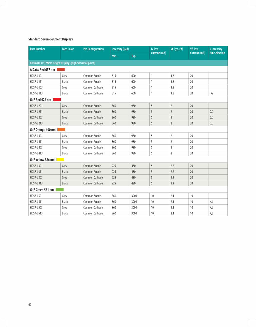
60
Part Number Face Color Pin Confi guration Intensity (µcd) Iv Test Current (mA)
Vf Typ. (V) Vf TestCurrent (mA)
2 IntensityBin Selection
Min. Typ.
8 mm (0.31”) Micro Bright Displays (right decimal point)
AlGaAs Red 637 nm
HDSP-U101 Grey Common Anode 315 600 1 1.8 20
HDSP-U111 Black Common Anode 315 600 1 1.8 20
HDSP-U103 Grey Common Cathode 315 600 1 1.8 20
HDSP-U113 Black Common Cathode 315 600 1 1.8 20 F,G
GaP Red 626 nm
HDSP-U201 Grey Common Anode 360 980 5 2 20
HDSP-U211 Black Common Anode 360 980 5 2 20 C,D
HDSP-U203 Grey Common Cathode 360 980 5 2 20 C,D
HDSP-U213 Black Common Cathode 360 980 5 2 20 C,D
GaP Orange 600 nm
HDSP-U401 Grey Common Anode 360 980 5 2 20
HDSP-U411 Black Common Anode 360 980 5 2 20
HDSP-U403 Grey Common Cathode 360 980 5 2 20
HDSP-U413 Black Common Cathode 360 980 5 2 20
GaP Yellow 586 nm
HDSP-U301 Grey Common Anode 225 480 5 2.2 20
HDSP-U311 Black Common Anode 225 480 5 2.2 20
HDSP-U303 Grey Common Cathode 225 480 5 2.2 20
HDSP-U313 Black Common Cathode 225 480 5 2.2 20
GaP Green 571 nm
HDSP-U501 Grey Common Anode 860 3000 10 2.1 10
HDSP-U511 Black Common Anode 860 3000 10 2.1 10 K,L
HDSP-U503 Grey Common Cathode 860 3000 10 2.1 10 K,L
HDSP-U513 Black Common Cathode 860 3000 10 2.1 10 K,L
Standard Seven-Segment Displays

61
Seve
n-Se
gmen
t Disp
lays
Part Number Face Color Pin Confi guration Intensity (µcd) Iv Test Current (mA)
Vf Typ. (V) Vf TestCurrent (mA)
2 IntensityBin Selection
Min. Typ.
10 mm (0.4”) Single Digit Displays (right decimal point)
AlGaAs Red 637 nm HDSP-F111 Black Common Anode 330 650 1 1.6 1
HDSP-F101 Grey Common Anode 330 650 1 1.6 1 E,F
HDSP-F113 Black Common Cathode 330 650 1 1.6 1
HDSP-F103 Grey Common Cathode 330 650 1 1.8 1 E,F
GaP Red 626 nm HDSP-F211 Black Common Anode 420 1200 5 2 20 D,E
HDSP-F201 Grey Common Anode 420 1200 5 2 20 D,E
HDSP-F213 Black Common Cathode 420 1200 5 2 20 D,E
HDSP-F203 Grey Common Cathode 420 1200 5 2 20 D,E
GaP Orange 603 nm HDSP-F411 Black Common Anode 420 1200 5 2 20
HDSP-F401 Grey Common Anode 420 1200 5 2 20
HDSP-F413 Black Common Cathode 420 1200 5 2 20
HDSP-F403 Grey Common Cathode 420 1200 5 2 20
GaP Yellow 586 nm HDSP-F301 Grey Common Anode 290 800 5 2.2 20 D,E
HDSP-F303 Grey Common Cathode 290 800 5 2.2 20 D,E
GaP Green 571 nm HDSP-F511 Black Common Anode 1030 3500 10 2.1 10 I,J
HDSP-F501 Grey Common Anode 1030 3500 10 2.1 10 J,K
HDSP-F513 Black Common Cathode 1030 3500 10 2.1 10 I,J
HDSP-F503 Grey Common Cathode 1030 3500 10 2.1 10 J,K
10 mm (0.4”) Overfl ow Displays (right decimal point)
AlGaAs Red 637 nm HDSP-F107 Grey Common Anode 330 650 1 1.6 1
HDSP-F108 Grey Common Cathode 330 650 1 1.6 1
GaP Red 626 nm HDSP-F207 Grey Common Anode 420 1200 5 2 20
HDSP-F208 Grey Common Cathode 420 1200 5 2 20
GaP Orange 603 nm HDSP-F407 Grey Common Anode 420 1200 5 2 20
HDSP-F408 Grey Common Cathode 420 1200 5 2 20
GaP Yellow 586 nm HDSP-F307 Grey Common Anode 290 800 5 2.2 20
HDSP-F308 Grey Common Cathode 290 800 5 2.2 20
GaP Green 571 nm HDSP-F507 Grey Common Anode 1030 3500 10 2.1 10
HDSP-F508 Grey Common Cathode 1030 3500 10 2.1 10
Standard Seven-Segment Displays

62
Part Number Face Color Pin Confi guration Intensity (µcd) Iv Test Current (mA)
Vf Typ. (V) Vf TestCurrent (mA)
Min. Typ.
10 mm (0.4”) Dual Digit Displays (right decimal point)
AlGaAs Red 637 nm
HDSP-G111 Black Common Anode 330 650 1 1.6 1
HDSP-G101 Grey Common Anode 330 650 1 1.6 1
HDSP-G113 Black Common Cathode 330 650 1 1.6 1
HDSP-G103 Grey Common Cathode 330 650 1 1.6 1
GaP Red 626 nm
HDSP-G211 Black Common Anode 420 1200 5 2 2
HDSP-G201 Grey Common Anode 420 1200 5 2 20
HDSP-G213 Black Common Cathode 420 1200 5 2 20
HDSP-G203 Grey Common Cathode 420 1200 5 2 20
GaP Orange 603 nm
HDSP-G411 Black Common Anode 420 1200 5 2 20
HDSP-G401 Grey Common Anode 420 1200 5 2 20
HDSP-G413 Black Common Cathode 420 1200 5 2 20
HDSP-G403 Grey Common Cathode 420 1200 5 2 20
GaP Yellow 586 nm
HDSP-G301 Grey Common Anode 290 800 5 2.2 20
HDSP-G303 Grey Common Cathode 290 800 5 2.2 20
GaP Green 571 nm
HDSP-G511 Black Common Anode 1030 3500 10 2.1 10
HDSP-G501 Grey Common Anode 1030 3500 10 2.1 10
HDSP-G513 Black Common Cathode 1030 3500 10 2.1 10
HDSP-G503 Grey Common Cathode 1030 3500 10 2.1 10
Standard Seven-Segment Displays

63
Seve
n-Se
gmen
t Disp
lays
Part Number Face Color Pin Confi guration Intensity Iv Test Current (mA)
Vf Typ. (V) Vf TestCurrent (mA)
Decimal Point
Min. Typ.
10 mm (0.4”) Slim Font Single Digit Displays
AlGaAs Red 637 nm HDSP-315H Grey Common Anode 180 650 1 1.8 1 Right
HDSP-316H Grey Common Cathode 180 650 1 1.8 1 Right
GaP Red 626 nm HDSP-315E Grey Common Anode 450 2600 10 1.9 10 Right
HDSP-316E Grey Common Cathode 450 2600 10 1.9 10 Right
GaP Red 626 nm — Low Current HDSP-315L Grey Common Anode 180 370 2 2.1 2 Right
HDSP-316L Grey Common Cathode 180 370 2 2.1 2 Right
GaP Yellow 586 nm HDSP-315Y Grey Common Anode 450 1800 10 2 10 Right
HDSP-316Y Grey Common Cathode 450 1800 10 2 10 Right
GaP Green 571 nm HDSP-315G Grey Common Anode 450 5000 10 2.1 10 Right
HDSP-316G Grey Common Cathode 450 5000 10 2.1 10 Right
Standard Seven-Segment Displays

64
Part Number Face Color Pin Confi guration Intensity Iv Test Current (mA)
Vf Typ. (V) Vf TestCurrent (mA)
2 Intensity Bin Selection
Decimal Point
Min. Typ.
10.9 mm (0.43”) Single Digit Displays
AlGaAs Red 637 nm HDSP-E101 Grey Common Anode 390 650 1 1.6 1 E,F Right
HDSP-E103 Grey Common Cathode 390 650 1 1.6 1 Right
GaP Red 626 nm 5082-7650 Red Common Anode 340 1115 5 2.1 20 D,E Left
5082-7651 Red Common Anode 340 1115 5 2.1 20 D,E Right
5082-7653 Red Common Cathode 340 1115 5 2.1 20 D,E Right
GaP Red 626 nm — Low Current HDSP-3350 Red Common Anode 200 300 2 1.6 2 Left
HDSP-3351 Red Common Anode 200 300 2 1.6 2 Right
HDSP-3353 Red Common Cathode 200 300 2 1.6 2 Right
GaP Yellow 586 nm 5082-7660 Yellow Common Anode 290 835 5 2.2 20 Left
5082-7661 Yellow Common Anode 290 835 5 2.2 20 Right
5082-7663 Yellow Common Cathode 290 835 5 2.2 20 Right
GaP Green 571 nm HDSP-4600 Grey Common Anode 1030 4000 10 2.1 10 Left
HDSP-4601 Grey Common Anode 1030 4000 10 2.1 10 Right
HDSP-4603 Grey Common Cathode 1030 4000 10 2.1 10 I,J Right
10 mm (0.4”) Slim Font Single Digit Displays
AlGaAs Red 637 nm HDSP-E106 Grey – 390 650 1 1.6 1 Right
GaP Red 626 nm HDSP-E106 Grey – 390 650 1 1.6 1 Right
GaP Red 626 nm — Low Current 5082-7656 Red – 340 1115 5 2.1 20 Right
GaP Yellow 586 nm 5082-7666 Yellow – 290 835 5 2.2 20 Right
GaP Green 571 nm HDSP-4606 Grey – 1030 4000 10 2.1 10 I,J Right
Standard Seven-Segment Displays

65
Seve
n-Se
gmen
t Disp
lays
Part Number Face Color Pin Confi guration Intensity Iv Test Current (mA)
Vf Typ. (V) Vf TestCurrent (mA)
2 Intensity Bin Selection
Decimal Point
Min. Typ.
13 mm (0.56”) Slim Font Displays
AlGaAs Red 637 nm HDSP-515H Grey Common Anode 180 650 1 1.8 1 G,H Right
HDSP-516H Grey Common Cathode 180 650 1 1.8 1 Right
GaP Red 626 nm HDSP-515E Grey Common Anode 450 2600 10 1.9 10 Right
HDSP-516E Grey Common Cathode 450 2600 10 1.9 10 Right
GaP Red 626 nm — Low Current HDSP-515L Grey Common Anode 180 370 2 2.1 2 F,G Right
HDSP-516L Grey Common Cathode 180 370 2 2.1 2 Right
GaP Yellow 586 nm HDSP-515Y Grey Common Anode 450 1800 10 2 10 Right
HDSP-516Y Grey Common Cathode 450 1800 10 2 10 Right
GaP Green 571 nm HDSP-515G Grey Common Anode 450 5000 10 2.1 10 Right
HDSP-516G Grey Common Cathode 450 5000 10 2.1 10 Right
Standard Seven-Segment Displays

66
Part Number Face Color Pin Confi guration Intensity (µcd) Iv Test Current (mA)
Vf Typ. (V) Vf TestCurrent (mA)
2 IntensityBin Selection
Min. Typ.
14.2 mm (0.56”) Single Digit Displays (right decimal point)
AlGaAs Red 637 nm
HDSP-H111 Black Common Anode 400 700 1 1.6 1 D,E
HDSP-H101 Grey Common Anode 400 700 1 1.6 1 D,E
HDSP-H113 Black Common Cathode 400 700 1 1.6 1
HDSP-H103 Grey Common Cathode 400 700 1 1.6 1 D,E
GaP Red 626 nm
HDSP-H211 Black Common Anode 900 2800 10 2 20 G,H
HDSP-5501 Grey Common Anode 900 2800 10 2.1 20 G,H
HDSP-H213 Black Common Cathode 900 2800 10 2 20 G,H
HDSP-5503 Grey Common Cathode 900 2800 10 2.1 20 G,H
GaP Red 626 nm — Low Current
HDSP-5551 Grey Common Anode 270 370 2 1.6 2
HDSP-5553 Grey Common Cathode 270 370 2 1.6 2 B,C
GaP Orange 600 nm
HDSP-H411 Black Common Anode 1190 2000 10 2 20
HDSP-H401 Grey Common Anode 1190 2000 10 2 20
HDSP-H413 Black Common Cathode 1190 2000 10 2 20
HDSP-H403 Grey Common Cathode 1190 2000 10 2 20
GaP Yellow 586 nm
HDSP-5701 Grey Common Anode 600 1800 10 2.1 20 F,G
HDSP-5703 Grey Common Cathode 600 1800 10 2.1 20 F,G
GaP Green 571 nm
HDSP-H511 Black Common Anode 900 2500 10 2.1 10 G,H
HDSP-5601 Grey Common Anode 900 2500 10 2.1 10 G,H
HDSP-H513 Black Common Cathode 900 2500 10 2.1 10 G,H
HDSP-5603 Grey Common Cathode 900 2500 10 2.1 10 G,H
Standard Seven-Segment Displays

67
Seve
n-Se
gmen
t Disp
lays
Part Number Face Color Pin Confi guration Intensity (µcd) Iv Test Current (mA)
Vf Typ. (V) Vf TestCurrent (mA)
2 IntensityBin Selection
Min. Typ.
14.2 mm (0.56”) Overfl ow Displays (right decimal point)
AlGaAs Red 637 nm
HDSP-H107 Grey Common Anode 400 700 1 1.6 1
HDSP-H108 Grey Common Cathode 400 700 1 1.6 1
GaP Red 626 nm
HDSP-5507 Grey Common Anode 900 2800 10 2.1 20 G,H
HDSP-5508 Grey Common Cathode 900 2800 10 2.1 20 G,H
GaP Red 626 nm — Low Current
HDSP-5557 Grey Common Anode 270 370 2 1.6 2
HDSP-5558 Grey Common Cathode 270 370 2 1.6 2
GaP Orange 600 nm
HDSP-H407 Grey Common Anode 1190 2000 10 2 20
HDSP-H408 Grey Common Cathode 1190 2000 10 2 20
GaP Yellow 586 nm
HDSP-5707 Grey Common Anode 600 1800 10 2.1 20
HDSP-5708 Grey Common Cathode 600 1800 10 2.1 20
GaP Green 571 nm
HDSP-5607 Grey Common Anode 900 2500 10 2.1 10
HDSP-5608 Grey Common Cathode 900 2500 10 2.1 10
Standard Seven-Segment Displays

68
Part Number Face Color Pin Confi guration Intensity Iv Test Current (mA)
Vf Typ. (V) Vf TestCurrent (mA)
2 Intensity Bin Selection
Decimal Point
Min. Typ.
20 mm (0.8”) Single Digit Displays
AlGaAs Red 637 nm HDSP-N100 Grey Common Anode 270 590 1 1.6 1 Left
HDSP-N101 Grey Common Anode 270 590 1 1.6 1 Right
HDSP-N103 Grey Common Cathode 270 590 1 1.6 1 Right
HDSP-N105 Grey Common Cathode 270 590 1 1.6 1 Left
GaP Red 626 nm HDSP-3901 Grey Common Anode 3350 7000
Peak(1/5 df)
2.6 100 E,F Right
HDSP-3903 Grey Common Cathode 3350 7000 2.6 100 E,F Right
HDSP-3905 Grey Common Cathode 3350 7000 2.6 100 Left
GaP Orange 600 nm HDSP-N401 Grey Common Anode 2230 –
Peak(1/5 df)
100 mA 2.6 100 Right
HDSP-N403 Grey Common Cathode 2230 – 2.6 100 Right
GaP Yellow 586 nm HDSP-4200 Grey Common Left Hand 2200 7000
Peak(1/5 df)
100 mA 2.6 100 Left
HDSP-4201 Grey Common Anode 2200 7000 2.6 100 Right
HDSP-4203 Grey Common Cathode 2200 7000 2.6 100 Right
HDSP-4205 Grey Common Cathode 2200 7000 2.6 100 Left
GaP Green 571 nm HDSP-8600 Grey Common Anode 680 1500 10 2.1 10 Left
HDSP-8601 Grey Common Anode 680 1500 10 2.1 10 E,F Right
HDSP-8603 Grey Common Cathode 680 1500 10 2.1 10 E,F Right
HDSP-8605 Grey Common Cathode 680 1500 10 2.1 10 Left
Standard Seven-Segment Displays
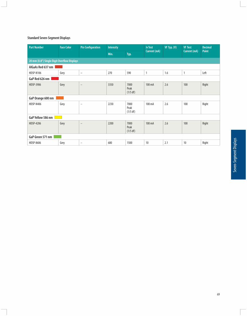
69
Seve
n-Se
gmen
t Disp
lays
Part Number Face Color Pin Confi guration Intensity Iv Test Current (mA)
Vf Typ. (V) Vf TestCurrent (mA)
Decimal Point
Min. Typ.
20 mm (0.8”) Single Digit Overfl ow Displays
AlGaAs Red 637 nm HDSP-N106 Grey – 270 590 1 1.6 1 Left
GaP Red 626 nm HDSP-3906 Grey – 3350 7000
Peak(1/5 df)
100 mA 2.6 100 Right
GaP Orange 600 nm HDSP-N406 Grey – 2230 7000
Peak(1/5 df)
100 mA 2.6 100 Right
GaP Yellow 586 nm HDSP-4206 Grey – 2200 7000
Peak(1/5 df)
100 mA 2.6 100 Right
GaP Green 571 nm HDSP-8606 Grey – 680 1500 10 2.1 10 Right
Standard Seven-Segment Displays

101
3
4
5 6
7
92
10°
7.62(0.300)
2.97(0.117)
2.54(0.100)
8
12.7 ±0.38(0.500 ±0.015)
4.19(0.165)
0.762(0.030)TYP.
2.97(0.117)
CL
7.62(0.300)
MITERED CORNER FOR PIN 1 REFERENCE
101
3
4
5 6
7
92
10°
7.62(0.300)
2.97(0.117)
2.54(0.100)
8
12.7 ±0.38(0.500 ±0.015)
4.19(0.165)
0.762(0.030)TYP.
2.97(0.117)
CL
7.62(0.300)
MITERED CORNER FOR PIN 1 REFERENCE
101
3
4
5 6
7
92
10°
2.97(0.117)
812.7 ±0.380
(0.500 ±0.015)
7.62(0.300)
2.97(0.117)
CL
METERED CORNER FOR PIN 1 REFERENCE
7.62(0.300)
5.18(0.204)
4.19(0.165)
CL
4.19(0.165)
5.08(0.200)
10°
5.72(0.225)
LHDP
RHDP
a
b
c
d
e
f g
1234567
141312111098
19.05 ±0.25(0.750 ±0.010)
10°
5.72(0.225)
0.25(0.010)
CL
1234567
141312111098
a
bc
d
e
RHDP
7.11(0.290)
70
Standard Seven-Segment Displays
7.6 mm (0.3”) Micro Bright Displays Package Dimension 7.6 mm (0.3”) Micro Bright Overfl ow Displays (Right Decimal Point) Package Dimension
7.6 mm (0.3”) Micro Bright Low Current Displays (Right Decimal Point) Package Dimension
7.6 mm (0.3”) Single Digit Displays Package Dimension
DIMENSIONS ARE IN MILLIMETERS (INCHES)
7.6 mm (0.3”) Overfl ow Displays Package Dimension
Part Number
HDSP- A151 A2117501 A213A401 A511A411 A51374017801A1537503A403A41374037803
Part Number
HDSP- A101 A1117511 A113A801A901A1037513A803A903
Part Number
5802- 761076117613762076217623360036013603
Part Number
5802- 761676263606
Part Number
HDSP- 7507A407740778077508A40874087808

7.62(10.300)
19.00(0.748)
1.00(0.039)
5.20(0.205)
10°
5.20(0.205)
0.90(0.035)
2- 1.1(0.043)
a
b
c
d
e
f g
1234567
141312111098
PIN 1
7.62(10.300)
19.00(0.748)
1.00(0.039)
10°
5.20(0.205)
0.90(0.035)
2- 1.1(0.043)
PIN 1
101
3
4
5 6
7
92
10°
1.0(0.039)
4.0(0.157)
a
b
c
d
e
f
DP
g8.0(0.315)
2.0(0.079)
2.5(0.098)
5.5(0.217)
811.0 ±0.2
(0.433 ±0.008)
CL
101
3
4
5 6
7
92
10°
10.16(0.400)8
12.90 ±0.50(0.508 ±0.020)
9.79(0.385)MAX.
5.59(0.220)
f b
e c
a
d
g
DP
CL
71
Seve
n-Se
gmen
t Disp
lays
10 mm (0.4”) Single Digit Displays (Right Decimal Point) Package Dimension
7.62 mm (0.3”) Single Digit Displays Package Dimension
8 mm (0.31”) Micro Bright Displays Package Dimension
DIMENSIONS ARE IN MILLIMETERS (INCHES)
Standard Seven-Segment Displays
Part Number
HDSP- 331E 331A331G 331Y
Part Number
HDSP- Uxxx
Part Number
5802- 333E 334E333G 334G333A 334A333Y 334Y
Part Number
HDSP- F111 F113F211 F213F511 F513F101 F103F201 F203F401 F403F411 F413F301 F303F501 F503F511 F513

101
3
4
5 6
7
92
10°
812.90 ±0.50
(0.508 ±0.020)
9.79(0.385)MAX.
b
c
DP
PLUS
MINUS
CL
17.20 ±0.25(0.670 ±0.01)
10°
10.16(0.400)
11.43(0.450)
22.86(0.900) MAX.
3.56(0.140)
5.590(0.220)
TYP.
10 916 15 14 13 12 11
1 2 3 4 5 6 7 8
101
3
4
5 6
7
92
10°
10.00(0.394)8
12.80 ±0.20
7.00 ±0.10
6.00(0.236)
0.90(0.035)
f b
e c
a
d
g
DP
CL
16.00(0.630)
5.90(0.232)
10°
18
10.16(0.400)
1.10(0.043)
10.160(0.400)
20.20(0.795)
1017 16 15 14 13 12 11
1 92 3 4 5 6 7 8
18.75(0.738)
1.20(0.047)
10.16(0.400)
5.51(0.220)
1.4(0.55)
5.54(0.218)
8°
+
PIN 1
6.00(0.236)
0.90(0.035)
10.00°
10.00(0.394)
1.85(0.073)
1.20(0.047)
72
10.16 mm (0.4”) Single Digit Displays Package Dimension
High Performance Seven-Segment Displays
10.16 mm (0.4”) Dual Digit Displays Package Dimension
DIMENSIONS ARE IN MILLIMETERS (INCHES)
10 mm (0.4”) Overfl ow Displays (Right Decimal Point) Package Dimension
10 mm (0.4”) Dual Digit Displays (Right Decimal Point) Package Dimension
10 mm (0.4”) Slim Font Single Digit Displays (Right Decimal Point) Package Dimension
Part Number
HDSP- F107 F108F207 F208F407 F408F307 F308F507 F508
Part Number
HDSP- 311E311G311A311Y
Part Number
HDSP- G101 G103G111 G113G201 G203G211 G213G301 G303G401 G403G411 G413G501 G503G511 G513
Part Number
HDSP- 315E 316E315L 316L315Y 316Y315G 316G30xE 30xG30xA 30xY
Part Number
HDSP- G0xE GOxGG0xA G0xY
Part Number
HDSP- 313E313G313A313Y

RHDP
10.92(0.430)
7.01(0.276)
CL
5.21(0.206)
6.36(0.250)
10°
3.18 (0.125)
a
b
c
d
e
fg
1234567
141312111098
101
3
4
5 6
7
92
10°
10.16(0.400)8
12.90 ±0.50(0.508 ±0.020)
9.79(0.385)MAX.
5.59(0.220)
f b
e c
a
d
g
DP
CL
LHDP
10.92(0.430)
7.01(0.276)
CL
5.08 (0.200)
6.36 (0.250)
10°
3.18 (0.125)
a
b
cd
e
fg
1234567
141312111098
17.20 ±0.25(0.670 ±0.01)
10°
10.16(0.400)
11.43(0.450)
22.86(0.900) MAX.
3.56(0.140)
5.590(0.220)
TYP.
10
9
1618 17 15 14 13 12 11
1 2 3 4 5 6 7 8
19.05 ±0.25(0.750 ±0.010)
RHDP
10.31(0.406)
10°
a
b
c
d
e
1234567
141312111098
19.05 ±0.25(0.750 ±0.010)
RHDP
10.36(0.408)
10°
a
b
c
d
e
1234567
141312111098
73
Seve
n-Se
gmen
t Disp
lays
10.9 mm (0.43”) Single Digit Displays (Right Decimal Point) Package Dimension
Standard Seven Segment Displays
10.9 mm (0.43”) Overfl ow Displays Package Dimension
10.9 mm (0.43”) Dual Digit Displays Package Dimension
10.9 mm (0.43”) Single Digit Displays Package Dimension
DIMENSIONS ARE IN MILLIMETERS (INCHES)
Part Number
HDSP- 3350
Part Number
HDSP- E101 E1033351 3353
5082- 7651 76537661 76634601 4603
Part Number
HDSP- 46065082- 7656 7666
Part Number
HDSP- E106 3356
Part Number
HDSP- G101 G103G201 G203G301 G303G401 G403G501 G503
Part Number
5802- 765076604600
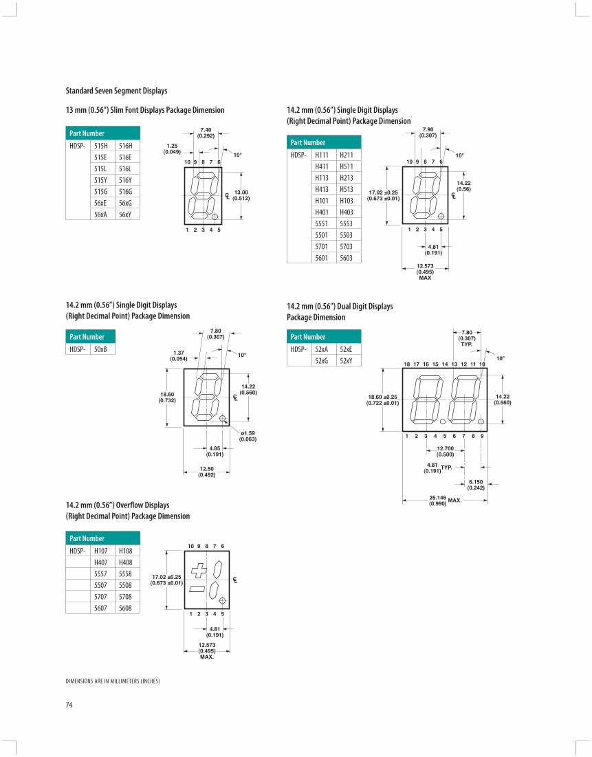
1
13.00(0.512)
7.40(0.292)
1.25(0.049)
2 3 4 5
10 9 8 7 610°
CL
1
14.22(0.56)
17.02 ±0.25(0.673 ±0.01)
12.573(0.495)MAX
7.90(0.307)
2 3 4 5
10 9 8 7 610°
4.81(0.191)
CL
14.22(0.560)
ø1.59(0.063)
18.60(0.732)
12.50(0.492)
7.80(0.307)
1.37(0.054)
10°
4.85(0.191)
CL 18.60 ±0.25(0.722 ±0.01)
7.80(0.307)TYP.
10°18
14.22(0.560)
12.700(0.500)
25.146(0.990) MAX.
4.81(0.191)
6.150(0.242)
TYP.
1017 16 15 14 13 12 11
1 92 3 4 5 6 7 8
1
17.02 ±0.25(0.673 ±0.01)
12.573(0.495)MAX.
2 3 4 5
9 8 7 6
4.81(0.191)
CL
10
74
14.2 mm (0.56”) Single Digit Displays (Right Decimal Point) Package Dimension
14.2 mm (0.56”) Overfl ow Displays (Right Decimal Point) Package Dimension
14.2 mm (0.56”) Dual Digit Displays Package Dimension
13 mm (0.56”) Slim Font Displays Package Dimension
DIMENSIONS ARE IN MILLIMETERS (INCHES)
Standard Seven Segment Displays
14.2 mm (0.56”) Single Digit Displays (Right Decimal Point) Package Dimension
Part Number
HDSP- 515H 516H515E 516E515L 516L515Y 516Y515G 516G56xE 56xG56xA 56xY
Part Number
HDSP- 52xA 52xE52xG 52xY
Part Number
HDSP- 50xB
Part Number
HDSP- H111 H211H411 H511H113 H213H413 H513H101 H103H401 H4035551 55535501 55035701 57035601 5603
Part Number
HDSP- H107 H108H407 H4085557 55585507 55085707 57085607 5608

1
14.22 ±0.05(0.560)
17.10 ±0.15(0.673)
12.40 ±0.15(0.488)
7.90 ±0.05(0.311)
1.50 ±0.05(0.059)
f b
e c
a
d
g
2 3 4 5
10 9 8 7 610°
4.85(0.191)
CL
1
23
4
5
6
7
8
9
18
1716
15
14
13
12
11
10
1.27(0.050)
8.25(0.325)
CL
CL
PACKAGE
RHDP
18.87(0.743)
9.39(0.370)
1.78(0.070) 8°
27.69 ±0.25(1.090 ±0.010)
20.32(0.800)
11.07(0.436)
8°
1
6
9
1.7(0.067)
13.05(0.514)
1.25(0.049)
8.2(0.323)
CL
CLCHARACTER
PACKAGE
16
RHDP
11.07(0.436)
8°
1
9
8
7
6
5
4
3
2
1.27(0.050) 8.25
(0.325)
CL
CLCHARACTER
PACKAGE
18
10
11
12
13
14
15
16
17
RHDP
27.69 ±0.25(1.090 ±0.010)
20.32(0.800)
11.07(0.436)8°
12
34
5
6
7
89
18
1716
1514
13
12
11
10
10.16(0.400)
13.08(0.515)
1.27(0.050) 8.25
(0.325)
CL
CLCHARACTER
PACKAGE
LHDP
75
Seve
n-Se
gmen
t Disp
lays
20 mm (0.8”) Single Digit Overfl ow Displays Package Dimension
20 mm (0.8”) Single Digit Displays Package Dimension
14.22 mm (0.56”) Single Digit Displays Package Dimension
DIMENSIONS ARE IN MILLIMETERS (INCHES)
Standard Seven-Segment Displays
Part Number
HDSP- 51xE 51xG51xA 51xY
Part Number
HDSP- N106 N4063906 42068606
Part Number
HDSP- 81xE 81xG
Part Number
HDSP- 3901 39034201 42038601 8603N101 N103N401 N403
Part Number
HDSP- N100 N1053900 39054200 42058600 8605

76
Description
Envisium Power PLCC-4 (plastic leaded chip carrier) surface-mount (SMT) LEDs represent the premier class of mid-power LEDs from Avago Technologies and Lumileds Lighting, utilizing the very best solid-state lighting technologies from these two industry leaders. Envisium Power PLCC-4 SMT LEDs off er unparalleled performance, reliability and design fl exibility. These LEDs produce higher light output with better fl ux performance compared to conventional PLCC-4 SMT LEDs.
Envisium Power PLCC-4 SMT LEDs, available in red, red-orange and amber, fi ll the need for mid-power illumination capabilities between Avago Technologies’ conventional PLCC-4 products, operating at up to 200 mW power levels, and Lumileds Lighting’s Luxeon LED light sources that operate at power levels of 1 watt and higher. The Power PLCC-4 package can be driven at high current due to its superior design, and is able to dissipate the heat more effi ciently than conventional PLCC-2 SMT LEDs. It also off ers much higher quality and reliability and superior mechanical characteristics to reduce tombstoning, prevent delamination and improve pick-and-place assembly.
The reliability and performance characteristics of these mid-power LEDs, such as their–40°C to +100°C operating temperature range, make them uniquely suitable for use in harsh conditions such as automotive applications, and in electronic signs and signals. To facilitate easy pick and place assembly, the LEDs are packed in EIA-compliant tape and reel. Every reel is shipped in single intensity and color bin (except for red) to provide close uniformity.
These LEDs are compatible with both IR solder refl ow and through-the-wave (TTW) soldering processes.
Features and Benefi ts
• Industry Standard PLCC-4 (plastic leaded chip carrier) form factor
• High reliability Power PLCC-4 package• Mid-power intensity with optimum fl ux
performance using TS AlInGaP (transparent substrate aluminum indium gallium phosphide) dice technologies
• Available in red, red orange and amber colors• High optical effi ciency• Higher ambient temperature at the same current
possible compared to PLCC-2• Super wide 120-degree viewing angle• Well-suited for backlighting applications• Supplied in EIA-standard 8 mm carrier tape on 7
inch reel• Compatible with both IR and TTW soldering
processes
Applications
• Interior automotive • Instrument panel backlighting • Central console backlighting • Navigation and audio system lighting • Push button backlighting• Exterior automotive • Turn signals • Side repeater lamps • CHMSLs (center high-mounted stop light) • Rear combination lamps • Puddle lights• Electronic signs and signals • Channel lettering • Contour lighting • Indoor variable message signs• Offi ce automation, home appliances, industrial
equipment • Front panel backlighting • Push button backlighting • Display backlighting
Envisium Power PLCC-4 Surface Mount LEDs
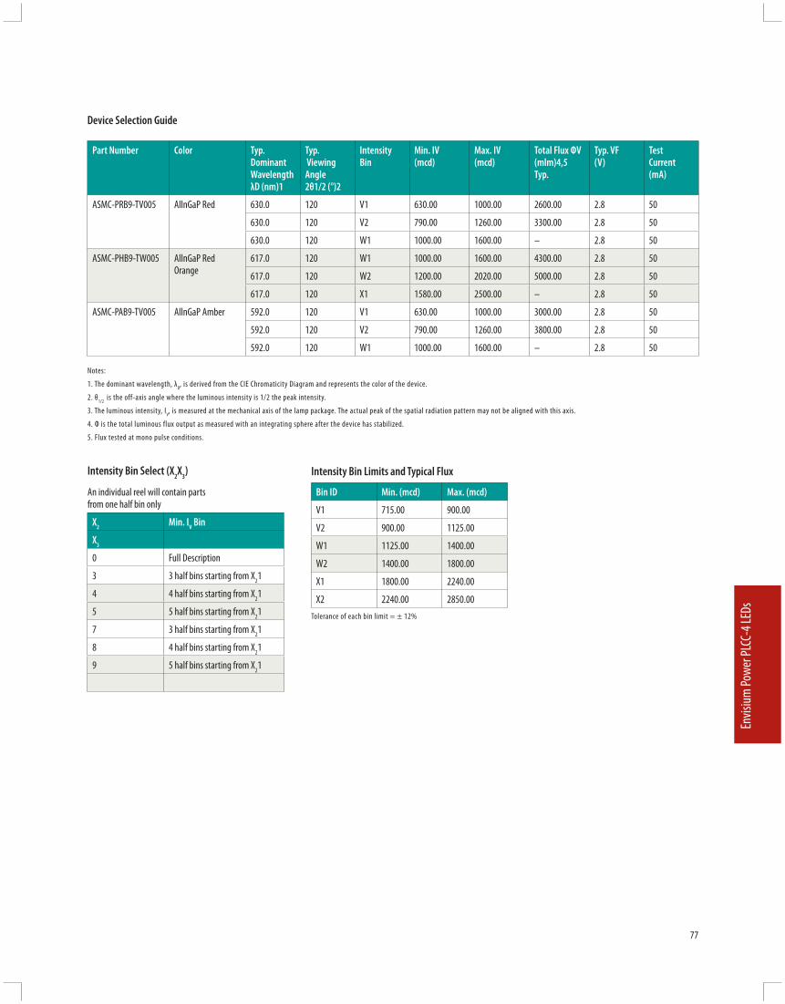
77
Envis
ium Po
wer P
LCC-
4 LED
s
Intensity Bin Select (X2X3)
An individual reel will contain parts from one half bin only
X2 Min. IV Bin
X3
0 Full Description
3 3 half bins starting from X21
4 4 half bins starting from X21
5 5 half bins starting from X21
7 3 half bins starting from X21
8 4 half bins starting from X21
9 5 half bins starting from X21
Intensity Bin Limits and Typical Flux
Bin ID Min. (mcd) Max. (mcd)
V1 715.00 900.00
V2 900.00 1125.00
W1 1125.00 1400.00
W2 1400.00 1800.00
X1 1800.00 2240.00
X2 2240.00 2850.00Tolerance of each bin limit = ± 12%
Part Number Color Typ. Dominant Wavelength λD (nm)1
Typ. Viewing Angle 2θ1/2 (°)2
Intensity Bin
Min. IV (mcd)
Max. IV (mcd)
Total Flux ΦV (mlm)4,5 Typ.
Typ. VF (V)
Test Current (mA)
ASMC-PRB9-TV005 AllnGaP Red 630.0 120 V1 630.00 1000.00 2600.00 2.8 50
630.0 120 V2 790.00 1260.00 3300.00 2.8 50
630.0 120 W1 1000.00 1600.00 – 2.8 50
ASMC-PHB9-TW005 AllnGaP Red Orange
617.0 120 W1 1000.00 1600.00 4300.00 2.8 50
617.0 120 W2 1200.00 2020.00 5000.00 2.8 50
617.0 120 X1 1580.00 2500.00 – 2.8 50
ASMC-PAB9-TV005 AllnGaP Amber 592.0 120 V1 630.00 1000.00 3000.00 2.8 50
592.0 120 V2 790.00 1260.00 3800.00 2.8 50
592.0 120 W1 1000.00 1600.00 – 2.8 50
Notes:
1. The dominant wavelength, λD, is derived from the CIE Chromaticity Diagram and represents the color of the device.
2. θ1/2 is the off-axis angle where the luminous intensity is 1/2 the peak intensity.
3. The luminous intensity, IV, is measured at the mechanical axis of the lamp package. The actual peak of the spatial radiation pattern may not be aligned with this axis.
4. Φ is the total luminous flux output as measured with an integrating sphere after the device has stabilized.
5. Flux tested at mono pulse conditions.
Device Selection Guide

78
Color Bin Select (X4)
An individual reel will contain parts from one half bin only
X2
0 Full Distribution
A 1 and 2 only
B 2 and 3 only
C 3 and 4 only
D 4 and 5 only
E 5 and 6 only
F 6 and 7 only
G 1, 2 and 3 only
H 2, 3 and 4 only
J 3, 4 and 5 only
K 4, 5 and 6 only
L 5, 6 and 7 only
M 1, 2, 3 and 4 only
N 2, 3, 4 and 5 only
P 3, 4, 5 and 6 only
Q 4, 5, 6 and 7 only
R 1, 2, 3, 4 and 5 only
S 2, 3, 4, 5 and 6 only
Color Bin Limits
Amber/Yellow Min.(nm)
Max.(nm)
1 582.0 584.5
2 584.5 587.0
3 587.0 589.5
4 589.5 592.0
5 592.0 594.5
6 594.5 597.0
Red Orange Min.(nm)
Max.(nm)
1 611.0 616.0
2 616.0 620.0
Red Min.(nm)
Max.(nm)
Full DistributionTolerance of each bin limit = ±1 nm
Packaging Option (X9)
Option Test Current Package Type Reel Size
5 50 mA Top Mount 7 inch
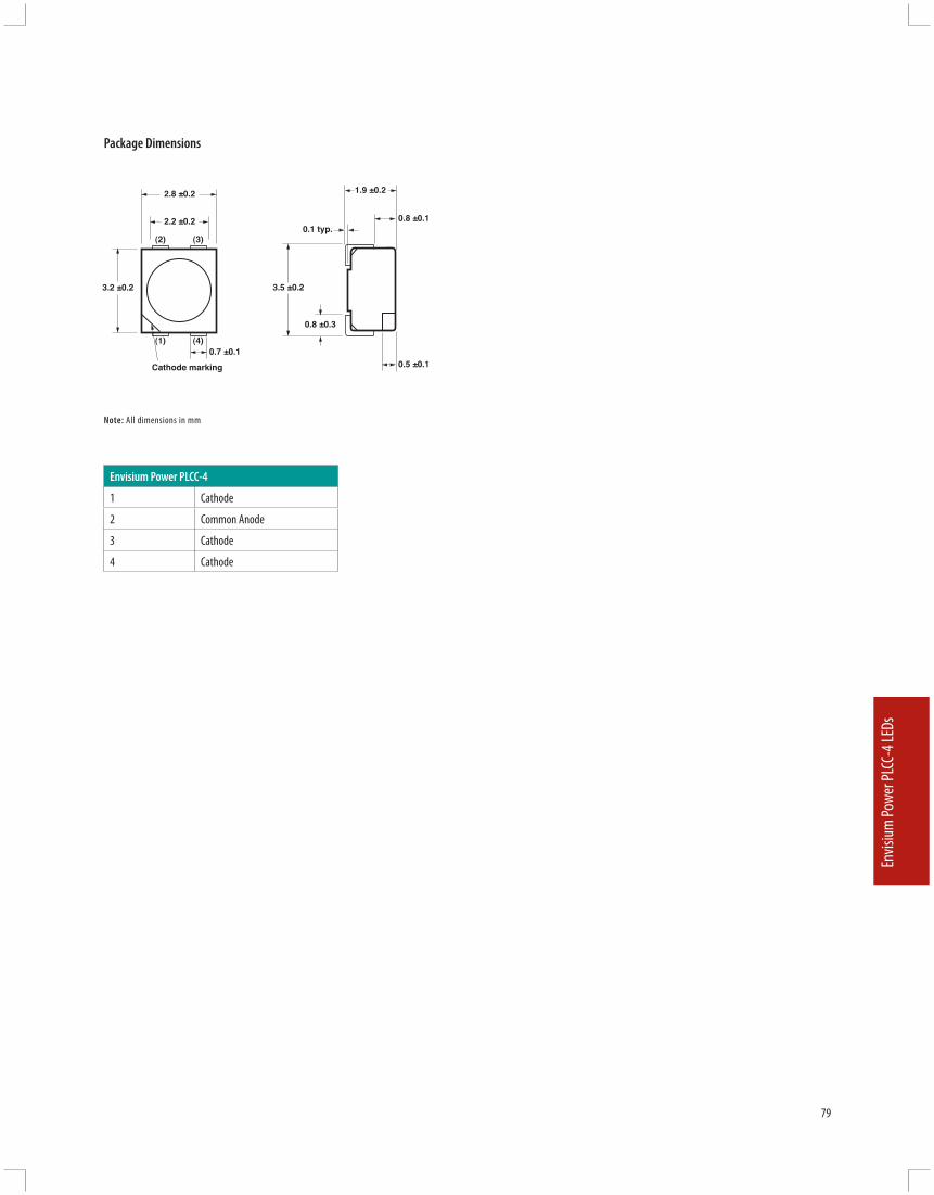
3.2 ±0.2
2.2 ±0.2
0.7 ±0.1(1) (4)
(2) (3)
2.8 ±0.2
Cathode marking
0.8 ±0.1
0.5 ±0.1
0.1 typ.
1.9 ±0.2
3.5 ±0.2
0.8 ±0.3
79
Envis
ium Po
wer P
LCC-
4 LED
s
Package Dimensions
Note: All dimensions in mm
Envisium Power PLCC-4
1 Cathode
2 Common Anode
3 Cathode
4 Cathode

For product information and a complete list of distributors, please go to our web site:
www.avagotech.com www.avagotech.com/ledAvago, Avago Technologies, and the A logo are trademarks of Avago Technologies, Pte. in the United States and other countries.Data subject to change. Copyright © 2006 Avago Technologies Obsoletes 5988-7211EN 5989-3958EN 1/3/06
About Avago Technologies
Avago Technologies is a leading global supplier of analog, mixed-signal and optoelectronic components and subsystems. The company serves three primary product categories comprising optoelectronics, RF/microwave components and enterprise ASICs.
Avago Technologies’ product solutions include fi ber optic transceivers and ICs for storage, computing and networking. For mobile handsets, Avago off ers RF components, infrared transceivers, light and proximity sensors, CMOS image sensors, and LEDs for camera fl ash as well as keypad and display backlighting. Avago’s optoelectronics solutions include a broad range of LEDs, the world’s most comprehensive line of isolation devices, an illumination and color management system for backlighting LCD fl at-panel TVs, motion control components for offi ce automation and industrial systems, optical navigation sensors for computer mice, and fi ber optics transmitters and receivers for industrial and automotive applications.
Avago Technologies combines the capabilities and track record of an established global leader with the vigor and responsiveness of a startup. Avago’s heritage of technical innovation dates back 40 years to its Agilent/Hewlett-Packard roots. During those years, the company amassed more than 2,000 patents and applications, and a reputation for innovation, quality and superior customer service.