ADI-1 - LED Indicating Display Controller - Kobold USA
40
Operating Instruction Operating Instruction for Universal Indicating Unit Norm signals 0/4-20 mA, 0-10 VDC Model: ADI-1V... 96x96 mm 96x96 ADI_1VD.pdf Stand: K02-0916
-
Upload
khangminh22 -
Category
Documents
-
view
0 -
download
0
Transcript of ADI-1 - LED Indicating Display Controller - Kobold USA

Operating InstructionOperating Instruction
for Universal Indicating Unit
Norm signals 0/4-20 mA, 0-10 VDC
Model: ADI-1V... 96x96 mm
96x96ADI_1VD.pdf Stand: K02-0916

Identification
Options – break-down ordering code:
A D I- 1 V 0 0 0 2 0 0Standard type ADI
Bargraph and Digital display, redBargraph 55 points 270°, digital display 5-digit, 14 mm 1
Type of displayVoltage-/current input 0-10 VDC / 0/4-20 mA V
Power supply100-240 VAC +/- 10% (50-60Hz) / DC 010-40 VDC / 18-30 VAC 50/60 Hz 3
Analogue outputwithout 00-10 VDC, 0/4-20 mA, 16 bit reversible 4
Sensor supplywithout 05 VDC / 20 mA U5 VDC / 20 mA U12 VDC / 50 mA, incl. digital input V24 VDC / 50 mA, incl. digital input W
Setpoints2 relay outputs 2
HousingHousingPanel mounting housing 0Field housing FField housing with wall mounting finally rotatable SField housing with pipe mounting R
Specialwithout 0without 0Special please specify in clear text Y
2

Contents
1. Brief description 42. Assembly 53 El t i l ti3. Electrical connection 64. Description of function and operation 95. Setting up the device 11
5.1. Switching on 115.2. Standard parameterisation (flat operation level) 11
Value assignment for the triggering of the signal input of the digital display and bargraph display
5.3. Programming interlock „RUN“ 15Activiation/Deactivation of the programming interlock or change into professional operation levelrespectively back into flat operation level
5.4. Extended parameterisation (professional operation level) 165.4.1. Signal input parameters „INP“
Value assignment for the triggering of the signal input incl. linearisation of the digital display and the bargraph display
5.4.2. General device parameters "FCT""FCT" Superior device functions like HOLD, TARA, min/max permanent, setpoint value function /
nominal value function, averaging, brightness control, as well as the control of the digital input andkeyboard layout
5.4.3. Bargraph functions „bar“Assignment of the bargraph to superior functions like min/max, totaliser, HOLD orsliding averaging
5.4.4. Safeafety parameters „Cod“ 25Assignment of user and master code for locking respectively for access to defined parameterslike e.g. analog output and alarms, etc.
5.4.5. Analog output parameters „Out“ 26Analog output functions
5.4.6. Relay functions „rel“ 28Parameters for the definition of the setpoints
5.4.7. Alarm parameters „AL1…AL4“ 30Actuator and dependencies of the alarms
5.4.8. Totaliser (volume metering) „tot“ 32Parameters for the calculation of the sum function
6. Reset to factory settings 33Reset parameters to delivery state
7 Alarms / Relay7. Alarms / Relay 34Functional principle of the switching outputs
8. Sensor alignment 35Diagram of functional sequences for sensors with existing adjustable resistor
9. Technical data 3610. Safety advices 3811. Error elimination 39
3
12. EU Declaration of Conformance 40
16
19
23

1. Brief description
1. Brief description
The panel meter instrument ADI-1V is a 5-digit digital display with a 55 points bargraph displayand two galvanic insulated setpoints; designed for direct current/direct voltage signals. Theconfiguration happens via four keys at the front The integrated programming interlock preventsconfiguration happens via four keys at the front. The integrated programming interlock preventsunrequested changes of parameters and can be unlocked again with an individual code. Optionalthe following functions are available: a supply for the sensor, a digital input for triggering of Hold(Tara), two analog outputs and interfaces for further evaluating in the unit. The electricalconnection is done via plug-in terminals on the back side.Selectable functions like e.g. the recall of the min/max-value, an averaging of the measuringsignals, a nominal presetting or setpoint presetting, a direct threshold value regulation duringoperation mode and further measuring setpoints for linearisation, complete the modern devicep g p , pconcept.
Technical features:
• red display of -19999…99999 digits• red 55 points bargraph• adjustable bar or dot operation or operation with permanent display of center point• min/max memory• 30 additional adjustable setpoints• display flashing at threshold value exceedance/undercut• zero-key for triggering of HOLD, TARA• permanent min/max-value recording• volume metering (totalisator)• mathematical functions like reciprocal value, square root, squaring or rounding• setpoint generator• sliding averaging• brightness control• brightness control• programming interlock via access code• protection class IP65 at the front• plug-in screw terminal• 2 relay outputs (changer)• optional: sensor supply and digital input• optional: analog output
4

2.1 Mounting panel housing
2. Assembly
Please read the Safety advice on page 37 before installation and keep this user manual for future reference.
56 mm
82 mm with plug-in terminal
Sealing
96 m
m9
Fixing
element
96 mm
7 mm
ele
1. After removing the fixing elements, insert the device.2. Check the seal to make sure it fits securely.3. Click the fixing elements back into place and tighten the clamping screws by hand.
Then use a screwdriver to tighten them another half a turn.
CAUTION! The torque should not exceed 0.1 Nm!
Please state you favorite dimension symbol in your order, they can not be exchanged afterwards!
5

2.2 Mounting field housing
2. Montage
For the assembling of ADI-1 field housing please use the M4 screws. Optionally the housing can be delivered with wall mounting or pipe mounting For the electrically connection please pull thebe delivered with wall mounting or pipe mounting. For the electrically connection please pull the housing lead back.
S 1 S2
P
OBOLD
ADI-1P
6

3. Electrical connection
3. Electrical connection
Model ADI-1V000200 with supply of 100-240 VACM d l ADI 1V300200 ith l f 10 40 VDCModel ADI-1V300200 with supply of 10-40 VDC
7

3. Electrical connection
Connection examples
ADI 1V d i ith t i t / lt i tADI-1V devices with current input / voltage input
ADI-1V devices in combination with a 2-wire-sensor 4-20 mA
ADI-1V devices in combination with a 3-wire-sensor 0/4-20 mA
ADI-1V devices in combination with a 3-wire-sensor 0-10 V
ADI-1V -devices with current input / voltage input and sensor supply
8

4. Description of function and operation
4. Description of function and operationOperationThe operation is divided into three different levels.
Menu level (delivery status)This level is for the standard settings of the device. Only menu items which are sufficent to set the device into operation are displayed. To get into the professional level, run through the menu level and parameterise “prof“ under menu item RUN.
Menu group level (complete function volume)Suited for complex applications as e.g. linkage of alarms, setpoint treatment, totaliser function etc. In this level ffunction groups which allow an extended parameterisation off the standard settings are availabe. To leave the menu group level, run through this level and parameterise „uloc„ under menu item RUN.
Parameterisation level:Parameter deposited in the menu item can here be parameterised. Functions, that can be changedor adjusted, are always signalised by a flashing of the display. Settings that are made in theparameterisation level are confirmed with [P] and thus safed By pressing the [O]-key“ it leads to aparameterisation level are confirmed with [P] and thus safed. By pressing the „[O]-key it leads to abreak-off of the value input and to a change into the menu level. All adjustments are safedautomatically by the device and changes into operating mode, if no further key operation is donewithin the next 10 seconds.
Level Key Description
Menu-level
Change to parameterisation level and deposited values.
Keys for up and down navigation in the menu level.
Change into operation mode.
Parameterisation-level
To confirm the changes made at the parameterisation level.
Adjustment of the value / the setting.
Change into menu level or break-off in value input.
Menu-group-level
Change to menu level.
Keys for up and down navigation in the menu group level.
Change into operation mode or back into menu level.
9

4. Description of function and operation
Function chart:
10

5. Setting up the device
5. Setting up the device
5.1. Switching on
Once the installation is complete, you can start the device by applying the voltage supply. Before, p , y y pp y g g pp y ,check once again that all electrical connections are correct.
Starting sequence
For 1 second during the switching-on process, the segment test (8 8 8 8 8 ) is displayed followed by an indication of the software type and, after that, also for 1 second the software version. After the starting sequence, the device switches to operation/display mode.
5 2 Standard parameterisation: (Flat operation level)
Menu level Parameterisation levelSelection of the input signal, TYPE: Default: sens.u
5.2. Standard parameterisation: (Flat operation level)
To parameterise the display, press the [P] key in operating mode for 1 second. The display then changes to the menu level with the first menu item TYPE.
Available as measuring input options are 0-20 mA, 4-20 mA or 0-10 VDC signals as works calibration (without application of the sensor signal) and SENSU (voltage) or SENSA (current)) as sensor calibration (with the sensor applied). Confirm the selection with [P] and the display switches back to menu level.
Setting the end value of the measuring range, END: Default: 10000
Set the end value from the smallest to the highest digit with [] [] and confirm each digit with [P]. A minus sign can only be parameterized on the highest value digit. After the last digit, the display switches back to the menu level. If Sens was selected as input option, you can only select between noca and cal. With noca, only the previously set display value is taken over, and with cal, the device takes over both the display value and the analogue input value.Setting the start/offsett vallue of the measuring range, offs: Default: 0
11
Enter the start/offset value from the smallest to the highest digit with [] [ ] and confirm each digit with [P]. After the last digit the display switches back to the menu level. If Sens was selected as input option, you can only select between noca and cal. With noca, only the previously set display value is taken over, and with cal, the device takes over both the display value and the analogue input value.

5. Setting up the device
Menu level Parameterisation level
Setting the decimal point, dot: Default: 0
The decimal point on the display can be moved with [] [] and confirmed with [P]. Thedisplay then switches back to the menu level again.
Setting up the display time, SEC: Default: 1.0
The display time is set with [] []. The display moves up in increments of 0.1 sec up to 1 sec and in increments of 1.0 sec up to 10.0 sec. Confirm the selection by pressing the [P] button. Th di l th it h b k t th l l i
then
The display then switches back to the menu level again.
Setting up the final value of the bargraph, ba.ENd: Default: 10000
Set the final value from the smallest to the highest digit with [] [] and confirm each digitg g [ ] [ ] gwith [P]. A minus sign can only be parameterised on the highest value digit. After the last digit,the display switches back to the menu level.
Setting up the initial value of the bargraph, ba.off: Default: 0
Set the initial value from the smallest to the highest digit with [] [] and confirm each digitwith [P]. A minus sign can only be parameterised on the highest value digit. After the last digit,the display switches back to the menu level.
Selection of the bargraph functions, ba.fct: Default: bar.fo
The bargraph can be displayed with the following possibilites: bars from left to right (top tobottom) or bars from right to left (bottom to top), bars from the middle, a dot display of thebargraph or a dot display with a permanently displayed midpoint. Confirm the selection bypressing the [P] button The display then switches back to the menu level again
12
pressing the [P] button. The display then switches back to the menu level again.

5. Setting up the device
Menu level Parameterisation level
Selection of analog output, Out.rA: Default: 4-20
Three output signals are available: 0-10 VDC, 0-20 mA and 4-20 mA, with this function, thedemanded signal is selected.demanded signal is selected.
Setting up the final value of the analog output, Out.En: Default: 10000
The final value is adjusted from the smallest digit to the highest digit with [] [] and digit bydigit confirmed with [P] A minus sign can only be parameterised on the highest digit After thedigit confirmed with [P]. A minus sign can only be parameterised on the highest digit. After thelast digit, the device changes back into menu level.
Setting up the initial value of the analog output, Out.OF: Default: 00000
The final value is adjusted from the smallest digit to the highest digit with [] [] and digit bydigit confirmed with [P]. A minus sign can only be parameterised on the highest digit. After thelast digit, the device changes back into menu level.
Threshold values / Limits, LI-1: Default: 2000
This value defines the threshold, that activates/deactivates an alarm.
Hysteresis for limit values, HY-1: Default: 00000
The delayed reaction of the alarm is the difference to the threshold value, which is defined bythe hysteresis.
13

5. Setting up the device
Menu level Parameterisation level
Function for threshold value undercut /exceedance, Fu-1: Default: high
A limit value undercut is selected with Louu (for LOW = lower limit value), a limit value exceedance with High (for HIGH = higher limit value). If e.g. limit value 1 is on a threshold level of 100 and allocated with function High, an alarm is activated by reaching of the threshold level. If the threshold value was allocated to Low, an alarm will be activated by undercutting the threshold value, as long as the hysteresis is zero.
Threshold values / Limits, LI-2: Default: 2000
This value defines the threshold, that activates/deactivates an alarm.
Hysteresis for limit values, HY-2: Default: 00000
The delayed reaction of the alarm is the difference to the threshold value, which is defined bythe hysteresis.
Function for threshold value undercut /exceedance, Fu-2: Deault high
A limit value undercut is selected with Louu (for LOW = lower limit value), a limit value exceedance with High (for HIGH = higher limit value). If e.g. limit value 1 is on a threshold level of 100 and allocated with function High, an alarm is activated by reaching of the threshold level. If the threshold value was allocated to Low, an alarm will be activated by undercutting the threshold value, as long as the hysteresis is zero.
14

5. Setting up the device
Menu level Parameterisation level
User code (4-digit number-combination, free available), U.CodE: Default: 0000
If this code was set (>0000), all parameters are locked for the user, if LOC has been selected before under menu item run. B y p r e s s i n g [P] for 3 seconds in operation mode, the display shhows COde. The U.Code needs t o be entered to get to the r e duced number of parameter sets. The code has to be entered befor each parameterisation, until the A.Code (Master code) unlocks all parameters again.
Master code (4-digit number-combination, free available), A.CodE: Default: 1234
All parameters can be unlocked with this code, after LOC has been activated under menu item run. B y p r e s s i n g [P] for 3 seconds in operation mode, the display shows COde and enables the user to reach all parametes by entering the A.codE. Under run the parameterisation can be activated permanently by selecting ULOC or ProF, thus at an anew pushing of [P] in operation mode, the code needs not to be entered again.
5.3. Programming interlock „run“Activation / deactivation of the programming lock or completion of the standard parameterisation with change into menu group level (complete function range), run: Default: uloc
With the navigation keys [] [ ], you can choose between the deactivated key lock Uloc (works setting) and the activated key lock Loc, or the change into the menu group level ProF. Confirm the selection with [P]. After this, the display confirms the settings with "- - - - - " , and automatically switches to operating mode. If Loc was selected, the keyboard is locked. To get back into the menu level, press [P] for 3 seconds in operating mode. Now enter the CODE (works setting 1 2 3 4 ) that appears using [] [ ] p l u s [P] to unlock the keyboard. FAIL appears if the input is wrong. To paparameterise further functions ProF needs to be set. The device confirms this setting with „- - - - - „ and changes automatically in operation mode. By pressing [P] for approx. 3 seconds in operation mode, the first menu group InP is shown in the display and thus confirms the change into the extended parameterisation. It stays activated as long as ULOC or LOC is entered in menu group RUN.
15

5. Setting up the device
5.4. Extended parameterisation (professional operation level)
5.4.1. Signal input parameters
Menu group level
Menu level
Menu level Parameterisation level
Selection of the input signal, TYPE: Default: sens.u
There are several measuring input options: 0-20 mA, 4-20 mA or 0-10 VDC signals as works calibration (without application of the sensor signal) and SenSU (voltage) or SENSA (current) as sensor calibration (with the sensor applied). Confirm the selection with [P] and the display switches back to menu level.
Setting the end value of the measuring range, END: Default: 10000
Set the end value from the smallest to the highest digit with [] [] and confirm each digit with [P]. A minus sign can only be parameterised on the highest value digit. After the last digit, the display switches back to the menu level. If Sens was selected as input option, you can only select between noca and cal. With noca, only the previously set display value is taken over, and with cal, the device takes over both the display value and the analogue input value.
Setting up the start/offset value of the measuring range, offs: Default: 0
Enter the start/offset value from the smallest to the highest digit with [] [ ] and confirm each digit with [P]. After the last digit the display switches back to the menu level. If Sens was selected as input option, you can only select between noca and cal. With noca, only the previously set display value is taken over, and with cal, the device takes over both the display value and the analogue input value.
16
Setting the decimal point, dot: Default: 00
The decimal point on the display can be moved with [] [] and confirmed with [P]. Thedisplay then switches back to the menu level again.

5. Setting up the device
Menu level Parameterisation level
Setting up the display time, SEC: Default: 1.0
The display time is set with [] []. The display moves up in increments of 0.1 sec up to 1 sec and in increments of 1.0 sec up to 10.0 sec. Confirm the selection by pressing the [P] button. The display then switches back to the menu level again
then
The display then switches back to the menu level again.
Rescaling the measuring input values, EndA: Default: 10000
With this function, you can rescale the input value of e.g. 19.5 mA (works setting) withoutapplying a measuring signal If sensor calibration has been selected these parameters are notapplying a measuring signal. If sensor calibration has been selected, these parameters are notavailable.
Rescaling the measuring input values, OFFA: Default: 0
With this function you can rescale the input value of e g 3 5 mA (works setting) withoutWith this function, you can rescale the input value of e.g. 3.5 mA (works setting) withoutapplying a measuring signal. If sensor calibration has been selected, these parameters are notavailable.
Setting up the tare/offset value, tArA: Default: 0
The given value is added to the linearised value. In this way, the characteristic line can beshifted by the selected amount.
Setting up the balance point, Adj.pt: Default:08000
The balance point for the final value can be chosen from the measuring range by Sens.u with 0…10 V or Sens.A with 0…20 mA in %. The preset 80.000% result from the widespread detuning of the melt pressure sensors.
Number of additional setpoints, SPCt: Default: 00
17
30 additional setpoints can be defined to the initial- and final value, so linear sensor values arenot linearised. Only activated setpoint parameters are displayed.

5. Setting up the device
Menu level Parameterisation level
Display values for setpoint, dIS.01 … dIS.30:
Under this parameter setpoints are defined according to their value. At the sensor calibration,like at Endwert/Offset, one is asked at the end if a calibration shall be activated.
Analog values for setpoints, InP.01 …InP.30:
The setpoints are always set according to the selected input signal. The desired analog valuescan be freely parametrised in ascending order.
Device undercut, dI.Und: Default: -i9999
With this function the device undercut (_ _ _ _ _) can be defined on a definite value. Exception isinput type 4-20 mA, it already shows undercut at a signal <1 mA, so a sensor failure is marked.
Display overflow, dI.OUE: Default: 99999
With this function the display overflow (_ __ _ _) can be defined on a definite value.
Back to menu group level, rEt:
With [P] the selection is confirmed and the device changes into menu group level „–INP-“.
18

5. Setting up the device
5.4.2. General device parameters
Menu group level
M l l P t i ti l l
Menu group level
Menu level
Menu level Parameterisation level
Display time, DISEC: Default: 01.0
then
The display is set up with [] []. Thereby it switches up to 1 second in increments of 0.1seconds and up to 10.0 seconds in increments of 1.0. With [P] the selection is confirmed andthe device changes into menu level.
Rounding of display values, round: Default: 00001
This function is for instable display values, where the display value is changed inincrements of 1, 5, 10 or 50. This does not affect the resolution of the optional outputs. With [P]the selection is confirmed and the device changes into menu level.
Arithmetic, ArItH: Default: n0
With this function the calculated value, not the measuring value, is shown in the display. With no, no calulation is deposited. With [P] the selection is confirmed and the device changes intomenu level.
Reciprocal Root extraction
Square
Sliding average determination, AVG: Default: 10
19
Here, the number of the meterings that need to be averaged is preset. The time of averaging resultlts o f the p r o duct of measuring time SEC and the a v e r a g e d metering AVG. With the selection of AVG in the menu level DISPL, the result will be shown in the display and evaluated via the alarms.
5. Setting up the device
Menu level Parameterisation level
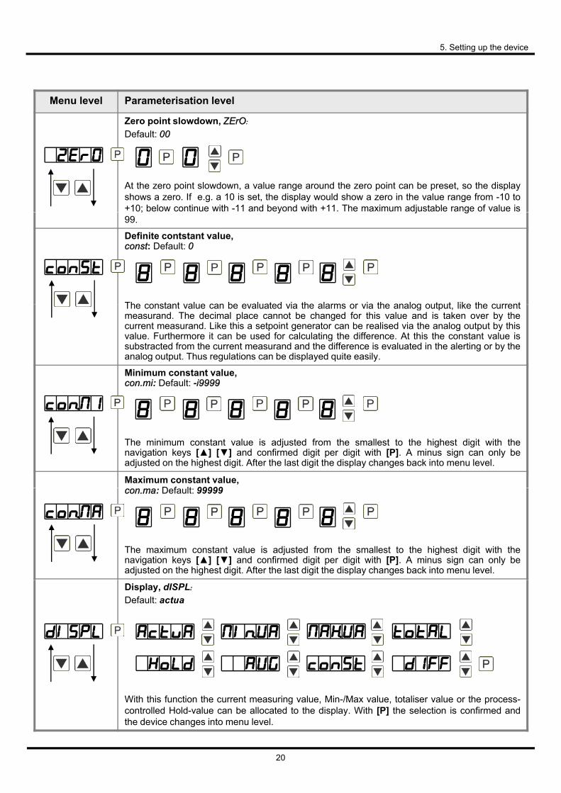
Zero point slowdown, ZErO: Default: 00
At the zero point slowdown, a value range around the zero point can be preset, so the displayshows a zero. If e.g. a 10 is set, the display would show a zero in the value range from -10 to+10; below continue with -11 and beyond with +11. The maximum adjustable range of value is; y j g99.
Definite contstant value, const: Default: 0
The constant value can be evaluated via the alarms or via the analog output like the currentThe constant value can be evaluated via the alarms or via the analog output, like the currentmeasurand. The decimal place cannot be changed for this value and is taken over by thecurrent measurand. Like this a setpoint generator can be realised via the analog output by thisvalue. Furthermore it can be used for calculating the difference. At this the constant value issubstracted from the current measurand and the difference is evaluated in the alerting or by theanalog output. Thus regulations can be displayed quite easily.
Minimum constant value, con.mi: Default: -i9999
The minimum constant value is adjusted from the smallest to the highest digit with thenavigation keys [] [] and confirmed digit per digit with [P]. A minus sign can only beadjusted on the highest digit. After the last digit the display changes back into menu level.
Maximum constant value, con.ma: Default: 99999
The maximum constant value is adjusted from the smallest to the highest digit with thenavigation keys [] [] and confirmed digit per digit with [P]. A minus sign can only beadjusted on the highest digit. After the last digit the display changes back into menu level.
Display, dISPL: Default: actua
20
With this function the current measuring value, Min-/Max value, totaliser value or the process-controlled Hold-value can be allocated to the display. With [P] the selection is confirmed andthe device changes into menu level.

5. Setting up the device
Menu level Parameterisation level
Brightness control, Light: Default: 10
The brightness of the display can be adjusted in 16 levels from 00 = very dark to 15 = verybright via this parameter or alternatively via the navigation keys from the outside. During theg p y g y gstart of the device, the level that is deposited under this parameter will always be used, eventhough the brightness has been changed via the navigation keys in the meantime.
Display flashing, FLASH: Default: no
A display flashing can be added as additional alarm function either to single or to a combination of off-limit condition. With no, no flashing is allocated.
Assignment (deposit) of key functions, tASt: Default: no
21
For the operation mode, special functions can be deposited on the navigation keys [] [], in particular this function is made for devices in housing size 48x24 which do not have a 4th key ([O]-key). If the min-/max-memory is activated with EHtr, all measured min/max-values are safed during operation and can be recalled via the navigation keys. The values get lost by re-start of the device. If the threshold value correction LI.12 or LI.34 is choosen, the values of the threshold can be changed during operation without disturbing the operating procedure. With tArA the device is taret to z e r o a n d safed permanently a s o ffset. The device confirms the correct taring by showing ooooo in the display Set.tA switches into the offset value and can be changed via the navigation keys [] [ ]. Via totAL the current value of the totaliser can be displayed for approx.7 seconds, after this the device changes back on the parameterised display value. If tot.rE is deposited, the totaliser can be set back by pressing of the navigation keys [] [ ], the device acknowledges this with ooooo in the display. The configuration of EHt.rE deletes the min/max-memory. Under ActuA the measurand is shown for approx. 7 seconds, after this the display returns to the parameterised display value. If AbS.UA (absolute value) was selected, the display shows the value that has been measured since voltage connection, without consideration of a previous taring. If no is selected, the navigation keys are without any function in the operation mode.

5. Setting up the device
Menu level Parameterisation level
Special function [O]-key, tASt.4: Default:no
…
For the opperation mode, special functions can be deposited on the [O]-Taste. This function is activated by pressing the key. With tArA the device is set temporarily on a parameterised value. The device acknowledges the correct taring with 00000 in the display. Set.tA switches into the offset value and can be changed via the navigation keys [] [ ]. Via totAL the current value of the totaliser can be displayed for approx. 7 seconds, after this the device switches back on the parameterised display value. If tot.rE is deposited, the totaliser can be set back by pressing of the navigation keys [] [ ], the device acknowledges this with 00000 in the display. EHt.rE deletes the min/max-memory. If HOLD has been selected, the moment can be hold constant by pressing the [O]-key, and is updated by releasing the key. Advice: Hold is activated only, i f HOLD is selected under parameter DISPL. ActuA shows the measuringg value for approx. 7 seconds, after this the device switches back on the parameterised display value. The same goes for AVG, here the sliding average values will be displayed. A sensor calibration is done by triggering of the digital input via se.cal, the flow diagram is shown in Chapter 9. T h e constant value const can be recalled via the digital input, or changed digit perdigit. At AL- 1…AL-4 an output can be set and therewith e.g. a setpoint adjustment can be done. If no is selected, the [O]-key is without any function in the operation mode.
Special function digital input, dIG.In: Default: no
…
In operation mode, the above shown parameters can be laid on the optional digital input, too. Function description see tASt.4.
Back to menu group level, rEt:
22
With [P] the selection is confirmed and the device changes into menu group level „– fct –“.

5. Setting up the device
M l l
5.4.3. Bargraph functions
Menu group level
Menu level
Menu level Parameterisation levelBargraph, Ba.src: Default: actua
With this function the following values can be allocated to the display: the current measuringvalue, min/max value, totaliser value or the process-controlled hold-value, the sliding averagevalue, the constant value or the difference between constant value and current value of thedisplay. With [P] the selection is confirmed and the device changes into menu level.
Setting up the final value of the bargraph, ba.ENd: Default: 10000
Set the final value from the smallest to the highest digit with [] [] and confirm each digitwith [P]. A minus sign can only be parameterised on the highest value digit. After the last digit,the display switches back to the menu level.
Setting up the initial value of the bargraph, ba.off: Default: 0
Set the initial value from the smallest to the highest digit with [] [] and confirm each digitwith [P]. A minus sign can only be parameterised on the highest value digit. After the last digit,the display switches back to the menu level.the display switches back to the menu level.
Selection of the bargraph functions, ba.fct: Default: bar.fo
23
The bargraph can be displayed with the following possibilities: bars forwards, bars backwards,bars starting out of the middle, bars from the middle, a dot display of the bargraph or a dotdisplay with a permanently displayed midpoint. Confirm the selection by pressing the [P]button. The display then switches back to the menu level again.

5. Setting up the device
Menu level Parameterisation levelBargraph alarm, bA.L1M: Default: no
If the alarms are triggered (AL1 to Al4), a flashing of the dots can be assigned to the bargraph by selecting Flash. If No was adjusted the bargraph remains statical. With [P] the selection is confirmed and the device changes into menu level.
Overflow behaviour, ba.oue: Default: limit
The overflow behaviour of the bargraph can be defined to identify and evaluate faulty signals, e.g. via a control system. Overflow Limit means the bargraph remains still at adjusted min- or max-value. The complete bargraph display flashes during an overflow, if Flash was selected. With [P] the selection is confirmed and the device changes into menu level.
Back to menu group level, rEt:
With [P] the selection is confirmed and the device changes into menu group level „– bar –“.
24

5. Setting up the device
Menu group level
5.4.4. Safety parameters
Menu group level
Menu level
Menu level Parameterisation level
Setting up the user code, U.Code: Default:0000
Via this code, reduced sets of paramameters outt.lle and all.llev can be unlocked, in case of a locked programming. There is no access to further parameters via this code. The U.CodE can only be changed via the correct input of the A.CodE (master code).
Master code, A.Code: Default:1234
By entering A.CodE the device will be unlocked and all parameters are released.
Release/lock analog output parameter, Out.LE: Default: all
Analog output parameter can be locked or released for the user:- A t En-oF the initial or final value can be changed in operation mode.
- A t Out.EO the output signal can be changed from e.g. 0-20 mA to 4-20 mA or 0-10 VDC. - A t ALL analog output parameters are released.- At no all analog output parameters are locked.
Release/lock alarm parameters, AL.LEU: Default: all
25
This parameter describes the user relase/user lock of the alarm.- LIMIt, here only the range of value of the threshold values 1-4 can be changed. -
ALrM.L, here the range of value and the alarm trigger can be changed.- ALL, all alarm parameters are released.- no, all alarm parameters are locked.

5. Setting up the device
Menu level Parameterisation level
Back to menu group level, rEt:
With [P] the selection is confirmed and the device changes into menu group level „– COD–“.
5 4 5 Analog output parameters5.4.5. Analog output parameters
Menu level group
Menu level
Menu level Parameterisation level
Selection reference of analog output, OutPt: Default: actua
The analog output signal can refer to different functions, in detail these are the current measurand, the min-value, the max-value, the totaliser-/sum function, the constant value or the difference between current measurand and constant value. If HoLd is selected, the signal of the analog output will be kept. It can be continued processing after a deactivation of Hold. W i t h [P] the selection is confirmed and the device changes into menu level.
Selection analog output, Out.rA: Default: 4-20
Three output signals are available 0-10 VDC, 0-20 mA and 4-20 mA. Select the demandedsignal with this function.
26

5. Setting up the device
Menu level Parameterisation levelSetting the final value of the analog output, Out.En: Default: 10000
The final value is adjusted from the smallest to the highest digit with [] [] and confirmeddigit per digit with [P]. A minus sign can only be parameterised on the highest digit. After thelast digit the device changes back into menu level.
Setting the initial value of the analog output, Out.OF: Default: 00000
The initial value is adjusted from the smallest to the highest digit with [] [] and confirmeddigit per digit with [P]. A minus sign can only be parameterised on the highest digit. After thelast digit the device changes back into menu level.
Overflow behaviour, O.FLoU: Default: edge
To recognise and evaluate faulty signals, e.g. by a controller, the overflow behaviour of the analogg outpput can be defined. As overflow can be seen either EdGGE,, that means the analogg output runs on the set limits e.g. 4 and 20 mA, or to.OFF (input value smaller than initial value, analog output switches on e.g. 4 mA), to.End (higher than final value, analog output switches on e.g. 20 mA). If to.MIn or to.MAX is set, the analog output switches on the smallest or highest possible binary value. This means that values of e.g. 0 mA, 0 VDC or values higher than 20 mA or 10 VDC can be reached. With [P] the selection is confirmed and the device changes into menu level.
Back to menu group level, rEt:
With [P] the selection is confirmed and the device changes into menu group level „– out –“.
27

5. Setting up the device
Menu group level
5.4.6. Relay functions
Menu group level
Menu level
Menu level Parameterisation levelAlarm relay 1, rEL-1:
Default:al-1
…. ….
Each setpoint (optional) can be linked up via 4 alarms (by default). This can either be inserted at activated alarms Al-1/4 or de-activated alarms Aln1/4. If LOGIC is selected, logical links are available in the menu level Log-1 and Com-1. One can only get to these two menu levels via LOGic, at all other selected functions, these two parameters are overleaped. Via On/OFF the setpoints can be activated/de-activated, in this case the output and the setpoint display are set/not set on the front of the device. The parameters Cal, Cal.of and CAL.en c a n o n l y b e u s e d in accordance with the semi-automatic calibration (Chapter 9. Sensor alignment). At Cal the relay switches during sensor calibration, at cal.of during offset calibration and at Cal.en during the calibration of the final value. With [P] the selection is confirmed and the device changes into menu level.
Logic relay 1, Log-1 Default: or
Here, the switching behaviour of the relay is defined via a logic link, the following schema describes these functions with inclusion of AL-1 and AL-2. This parameter is only possible if LOgic was selected under REl-1.
A1 v A2 As soon as a selected alarm is activated, the relayoperates. Equates to operating current principle.
A1 v A2 = A1 Λ A2 The relay operates only, if no selected alarm isactive. Equates to quiescent current principle.
A1 Λ a2 The relay operates only, if all selected alarms areactive.
A1 Λ A2 = A1 v A2 As soon as a selected alarm is not activated the
____ _ _
____ _ _
28
A1 Λ A2 = A1 v A2 As soon as a selected alarm is not activated, therelay operates.
With [P] the selection is confirmed and the device changes into menu level.

5. Setting up the device
Menu level Parameterisation level
Alarms for relay 1, CoM-1: Default:a.1
The allocation of the alarms to relay 1 happens via this parameter, one alarm or a group of alarms can be chosen. This parameter is only available if LOGIC was selected under REl-1. With [P] the selection is confirmed and the device changes into menu level.
….
Alarm relay 2, rEL-2:
Default:al-2
…. ….
Each setpoint (optional) can be linked up via 4 alarms (by default). This can either be inserted at activated alarms Al-1/4 or de-activated alarms Aln1/4. If LOGIC is selected, logical links are available in the menu level Log-1 and Com-1. One can only get to these two menu levels via LOGic, at all other selected functions, these two parameters are overleaped. Via On/OFF the setpoints can be activated/de-activated, in this case the output and the setpoint display are set/not set on the front of the device. The parameters Cal, Cal.of and CAL.en can only be u s e d in accordance with the semi-automatic calibration (Chapter 9. Sensor alignment). At Cal the relay switches during sensor calibration, at cal.of during offset calibration and at Cal.en during the calibration of the final value. With [P] the selection is confirmed and the device changes into menu level.
Logic relay 2, Log-2:Default: OR
Here, the switching behaviour of the relay is defined via a logic link, the following schema describes these functions with inclusion of AL-1 and AL-2. This parameter is only possible if LOgic was selected under REl-1.
A1 v A2 As soon as a selected alarm is activated, the relayoperates. Equates to operating current principle.____ _ _
A1 v A2 = A1 Λ A2 The relay operates only, if no selected alarm isactive. Equates to quiescent current principle.
A1 Λ a2 The relay operates only, if all selected alarms areactive.
A1 Λ A2 = A1 v A2 As soon as a selected alarm is not activated, therelay operates.
With [P] the selection is confirmed and the device changes into menu level.
____ _ _
29

5. Setting up the device
Menu level Parameterisation level
Alarms for relay 2, CoM-2: Default:A.2
The allocation of the alarms to relay 1 happens via this parameter, one alarm or a group of alarms can be chosen. This parameter is only available if LOGIC was selected under REl-1. With [P] the selection is confirmed and the device changes into menu level.
….
Back to menu group level, rEt:
With [P] the selection is confirmed and the device changes into menu group level „– rel –“.
Menu group level
5.4.7. Alarm parameters
Menu level
Menu level Parameterisation level
Dependency alarm1, ALrM.1: Default: actua
The dependency of alarm 1 can be related to special functions, in detail these are the current measuring value, the min-value, the max-value, the totaliser-/sum-value, the constant value or the difference between the current measurand and the constant value. If Hold was selected, then the alarm is hold and processed just after deactivation of HOLD. EHtEr causes the dependency either by pressing the [O]-key on the front of the housing or by an external signal via the digital input. With [P] the selection is confirmed and the device changes into menu level.Example:
30
Example:By using the maximum value Alarm.1 = Max.va in combination with a threshold monitoring Fu-1 = High, an alarm confirmation can be realised. Use the navigation keys, the fourth key or the digital input for confirmation.

5. Setting up the device
Menu level Parameterisation level
Threshold values / Limit values, LILI-1: Default: 2000
The limit value defines the threshold, that activates/deactivates an alarm.
Hysteresis for threshold values, HY-1: Default: 00000
The delayed reaction of the alarm is the difference to the threshold value, which is defined bythe hysteresis.
Function for threshold value undercut/exceedance, FFu-1: Default: high
A limit value undercut is selected with Louu (for LOW = lower limit value), a limit value exceedance with High (for HIGH = higher limit value). If e.g. limit value 1 is on a threshold level of 100 and allocated with function High, an alarm is activated by reaching the threshold level. If the threshold value was allocated to Low, an alarm will be activated by undercutting the threshold value, as long as the hysteresis is zero.
Switching-on delay, ton-1: Default: 000
For limit value 1 one can preset a delayed switching-on of 0-100 seconds.
Switching-off delay, toF-1: Default: 000
For limit value 1 one can preset a delayed switching-off of 0-100 seconds.
Back to menu group level, rEt:
31
With [P] the selection is confirmed and the device changes into menu group level „– Al1 –“.
The same applies for Al2 to al8.

5. Setting up the device
Menu group level
5.4.8. Totaliser (Volume metering)
Menu group level
Menu level
Menu level Parameterisation level
Totaliser state, total:Default: off
The totaliser makes measurements on a time base of e.g. l/h possible, at this the scaled input signal is integrated by a time and steadily (select Stead) or temporarily (select temp) safed. Select the constant storage for consumption measurements and the quick storage for frequently filling processes. During the constant storage STEAD the current sum value is safed at each totaliser reset. Furthermore it is safed every 30 minutes in the not-volatile storage of the device. If Off is selected, the function is deactivated. With [P] the selection is confirmed and the device changes into menu level.
Timef
base, t.base: Default: sec
Under this parameter the time base of the measurement can be preset in seconds, minutes orhours.
Totaliser factor, Facto: Default: 1e0
At this, the factor (1E0…1E6) respectively the divisor for the internal calculation of themeasuring value is assigned.
…
SettingSetting upup thethe decimaldecimal pointpoint forfor thethe totaliser, tot.ddt:Default: 0
32
The decimal point of the device can be adjusted with the navigation keys [] []. With [P] theselection is confirmed and the device changes into menu level.

6. Reset to default values
Menu level Parameterisation level
Totaliser reset, tot t t.re:Default: 000
The reset value is adjusted from the smallest to the highest digit with the navigation keys [][] and digit per digit confirmed with [P]. After the last digit, the display switches back to themenu level. The activator for the reset is parameter driven via the 4th key or via the optionalp y pdigital input.
Back to menu group level, rEt:
With [P] the selection is confirmed and the device changes into menu group level „– tot –“ .
Menu group level
Programming interlock, run:
Description see page 11, menu level run
The following procedure should be used:
6. Reset to default valuesTo return the unit to a defined basic state, a reset can be carried out to the default values.
• Switch off the power supply• Press button [P]• Switch on voltage supply and press [P]-button until „- - - - -“ is shown in the display.
With reset, the default values of the program table are loaded and used for subsequent operation This puts the unit back to the state in which it was supplied
33
operation. This puts the unit back to the state in which it was supplied.
Caution! All application-related data are lost.

7. Alarms / Relays
This device has 4 virtual alarms that can monitor one limit value in regard of an undercut or exceedance. Each alarm can be allocated to an optional relay output S1-S2; furthermore alarms can be controlled by events like e g hold value or min /max value
7. Alarms / Relays
be controlled by events like e.g. hold-value or min-/max-value.
Function principle of alarms / relays
Alarm / Relay x deactivated, instantaneous value, min-/max-value, hold-value, totaliser value, sliding average value, constant value, difference between instantaneous value and constant value or an activation via the digital inputvia the digital input
Switching threshold Threshold / limit value of the change-over
Hysteresis Broadness of the window between the switching thresholds
Working principle Operating current / Quiescent current
Operating currentOperating currentBy operating current the alarm S1-S2 is off below the threshold and on on reaching the threshold.
Quiescent currentBy quiescent current the alarm S1-S2 is on below the threshold and switched off on reaching the thresholdon reaching the threshold.
Switching-on delayThe switching-on delay is activated via an alarm and e.g. switched 10 seconds after reaching the switching threshold, a short-term exceedance of the switching value does not cause an alarm, respectively does not cause a switching
34
respectively does not cause a switching operation of the relay. The switching-off delay operates in the same way, keeps the alarm / the relay switched longer for the parametrised time.
8. Sensor alignment offset / final value
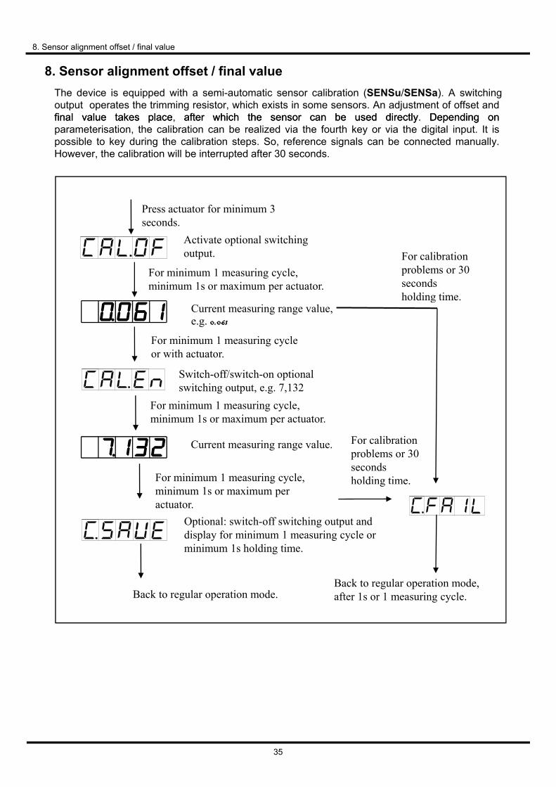
8. Sensor alignment offset / final valueThe device is equipped with a semi-automatic sensor calibration (SENSu/SENSa). A switching output operates the trimming resistor, which exists in some sensors. An adjustment of offset and finalfinal valuevalue takestakes plaplaccee, aftafterer whwhichich thethe sensosensorr cancan bebe useusedd directlydirectly. DependinDependingg onon parameterisation, the calibration can be realized via the fourth key or via the digital input. It is possible to key during the calibration steps. So, reference signals can be connected manually. However, the calibration will be interrupted after 30 seconds.
Press actuator for minimum 3Press actuator for minimum 3 seconds.
For minimum 1 measuring cycle, minimum 1s or maximum per actuator.
Activate optional switching output. For calibration
problems or 30 seconds holding time.
Current measuring range value, e.g. 0.061
For minimum 1 measuring cycle or with actuator.
Switch-off/switch-on optional switching output, e.g. 7,132
g
For minimum 1 measuring cycle, minimum 1s or maximum per actuator.
Current measuring range value.
g p g
For minimum 1 measuring cycle,
For calibration problems or 30 seconds holding time.
minimum 1s or maximum per actuator.
Optional: switch-off switching output and display for minimum 1 measuring cycle or minimum 1s holding time.
o d g e.
Back to regular operation mode.Back to regular operation mode, after 1s or 1 measuring cycle.
35

9. Technical data
Panel meter
Dimensions Field housing: 96x96x56 mm (BxHxD)
9. Technical data
Dimensions Field housing: 96x96x56 mm (BxHxD)
Installation housing: 96x96x82 mm (BxHxD) including plug-in terminal
Panel cut-out 91.0+0.6 x 91.0+0.6 mm
Wall thickness up to 10 mm
Fixing screw elements
Material LEXAN 500R blackMaterial LEXAN 500R, black
Sealing material EPDM, 65 Shore, black
Protection class standard IP65 (front), IP00 (back side)
Weight approx. 330 g
Connection plug-in terminal; wire cross section up to 2.5 mm2
DisplayDisplay
Digit height 14 mm
Segment colour red
Display range -19999 to 99999
Setpoints one LED per setpoint
Overflow horizontal bars at the topp
Underflow horizontal bars at the bottom
Display time 0.1 to 10.0 seconds
Bargraph 55 segments in a 270° angle
Bragraph colour red
Input Measuring range Ri Measuring error Digit
min. -22…max. 24 mA 0/4 – 20 mA ~100 Ω 0.1 % of measuring range ±1
min. -12…max. 12 VDC 0-10 VDC ~200 kΩ 0.1 % of measuring range ±1
Digital input < 2,4 V OFF, 10 V ON, max. 30 VDCRI ~ 5 kΩ
Accuracy
Drift of temperature 100 ppm / K
Measuring time 0.1…10.0 seconds
Measuring principle U/F-conversion
Resolution approx. 18 Bit at 1 second measuring time
36

Output
Sensor supply 24 VDC / 50 mA; 12 VDC / 50 mA; 5 VDC / 20 mA
10. Technical data
Sensor supply 24 VDC / 50 mA; 12 VDC / 50 mA; 5 VDC / 20 mA
Analog output 0/4-20 mA /burden 350 Ω or 0-10 VDC / 10 kOhm, 16 Bit
Switching outputs
Relay with change-over contactsSwitching cycles
250 VAC / 5 AAC; 30 VDC / 5 ADC30 x 103 at 5 AAC, 5 ADC ohm resitive burden10 x 106 mechanicallyDivision according to DIN EN50178 / Characteristics accrording to DIN EN60255
Memory EEPROM
Data life ≥ 100 years at 25°Cy
Ambient conditions
Working temperature 0°…50°C for panel meters, -20°…60°C for built-on devices
Storing temperature -20…80°C
Weathering resistance relative humidity 0-80% on years average without dew
Height up to 2000 m above sea level
EMV EN 61326
CE-sign Conformity according to directive 2004/108/EG
Safety standard Accroding to low voltage directive 2006/95/EGEN 61010; EN 60664-1
37

10. Safety advices
Please read the following safety advice and the assembly chapter 1 before installation and keep it for future reference.
10. Safety advices
Proper use
The ADI-1V-device is designed for the evaluation and display of sensor signals.
Danger! Careless use or improper operation can result in personal injury and/or damage to the equipment.
Control of the device
The panel meters are checked before dispatch and sent out in perfect condition. Should there be any visible damage, we recommend close examination of the packaging. Please inform the supplier immediately of any damage.
Installation
The ADI-1V-device must be installed by a suitably qualified specialist (e.g. with a qualification in industrial electronics).
Notes on installation
• There must be no magnetic or electric fields in the vicinity of the device, e.g. due to transformers,mobile phones or electrostatic dischargemobile phones or electrostatic discharge.
• The fuse rating of the supply voltage should not exceed a value of 6A N.B. fuse.
• Do not install inductive consumers (relays, solenoid valves etc.) near the device and suppressany interference with the aid of RC spark extinguishing combinations or free-wheeling diodes.
• Keep input, output and supply lines separate from one another and do not lay them parallel witheach other. Position “go” and “return lines” next to one another. Where possible use twisted pair.So you receive best measuring resultsSo, you receive best measuring results.
• Screen off and twist sensor lines. Do not lay current-carrying lines in the vicinity. Connect thescreening on one side on a suitable potential equaliser (normally signal ground).
• The device is not suitable for installation in areas where there is a risk of explosion.
• Any electrical connection deviating from the connection diagram can endanger human life and/orcan destroy the equipment.
• The terminal area of the devices is part of the service. Here electrostatic discharge needs to beavoided. Attention! High voltages can cause dangerous body currents.
• Galvanic insulated potentials within one complex need to be placed on a appropriate point(normally earth or machines ground). So, a lower disturbance sensibility against impacted energycan be reached and dangerous potentials, that can occur on long lines or due to faulty wiring, canbe avoided.
38

11. Error elimination
Error description Measures
1 The unit permanently indicates • The input has a very high measurement check
11. Error elimination
1. The unit permanently indicates overflow.
• The input has a very high measurement, checkthe measuring circuit.
• With a selected input with a low voltage signal, itis only connected on one side or the input is open.
• Not all of the activated setpoints areparameterised. Check if the relevant parametersare adjusted correctly.
2. The unit permanently showsunderflow.
• The input has a very low measurement, check themeasuring circuit .
• With a selected input with a low voltage signal, itis only connected on one side or the input is open.
• Not all of the activated setpoints areparameterised. Check if the relevant parametersare adjusted correctly.
3. The word "HELP " lights up in the 7-segment display.
• The unit has found an error in the configurationmemory. Perform a reset on the default valuesand re-configure the unit according to yourapplication.
4. Program numbers for parameterising of the input are not accessible.
• Programming lock is activated• Enter correct code
5. "Err1" lights up in the 7-segment display
• Please contact the manufacturer if errors of thiskind occur.
6. The device does not react as expected.
• If you are not sure if the device has beenparameterised before, then follow the steps aswritten in chapter 6. and set it back to its deliverystatus.
39

12. EU Declaration of Conformance
12. Declaration of Conformance
40
We, KOBOLD Messring GmbH, Hofheim-Ts, Germany, declare under our sole responsibility that the product:
Universal Indicating Unit Model: ADI-1V...
to which this declaration relates is in conformity with the standards noted below:
EN 61010-1:2010 Safety requirements for electrical equipment for measurement, control and laboratory use - Part 1: General requirements
EN 61326-1:2013 Electrical equipment for measurement, control and laboratory use - EMC requirements - Part 1: General requirements
EN 55011:2009 + A1:2010 Industrial, scientific and medical equipment - Radio-frequency disturbance characteristics - Limits and methods of measurement
Also the following EC guidelines are fulfilled:
2014/30/EU 2014/35/EU 2011/65/EU
EMC Directive Low Voltage Directive RoHS (category 9) industrial monitoring and control instruments, compliant, no CE-marking for the transitional period until 2017
Hofheim, 12. Sept. 2016 H. Peters
General Manager M. Wenzel
Proxy Holder