Baro-Display LED - Biral
30
THE WORLD OF WEATHER DATA - THE WORLD OF WEATHER DATA - THE WORLD OF WEATHER DATA Baro-Display LED 3.1156.0x.00x Operating Instructions 021566/01/08 ADOLF THIES GmbH & Co. KG Hauptstraße 76 37083 Göttingen Germany Box 3536 + 3541 37025 Göttingen Phone +49 551 79001-0 Fax +49 551 79001-65 www.thiesclima.com [email protected]
-
Upload
khangminh22 -
Category
Documents
-
view
2 -
download
0
Transcript of Baro-Display LED - Biral
THE
WOR
LD O
F W
EATH
ER D
ATA
- TH
E W
ORLD
OF
WEA
THER
DAT
A - T
HE W
ORLD
OF
WEA
THER
DAT
A
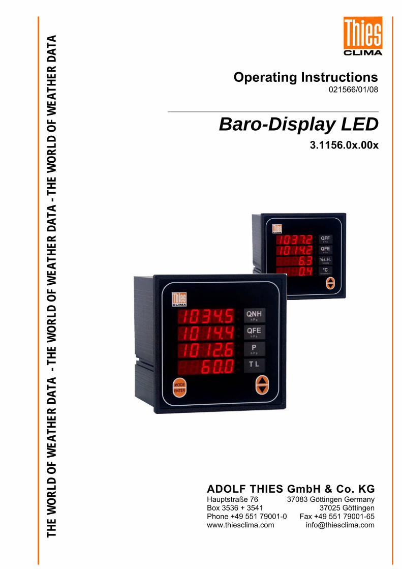
Baro-Display LED3.1156.0x.00x
Operating Instructions021566/01/08
ADOLF HauptstraßeBox 3536 + Phone +49 5www.thiescli
THIES GmbH & Co. KG 76 37083 Göttingen Germany 3541 37025 Göttingen 51 79001-0 Fax +49 551 79001-65 ma.com [email protected]
Safety Instructions, Environment, Documentation Operating Instructions
• © Copyright Adolf Thies GmbH & Co KG, Göttingen / Germany
• Although this document has been drawn up with due care, Adolf Thies GmbH & Co KG can accept no liability whatsoever for any technical and typographical errors or omissions in this document that might remain.
• We can accept no liability whatsoever for any losses arising from the information contained in this document.
• Subject to modification in terms of content.
• The device should not be passed on without the/these operating instructions.
Safety Instructions• Read through the operating instructions before using the device for the first time.
• The device may only be fitted and connected by a qualified technician who is familar with and observes the engineering regulations, provisions and standards applicable in each case.
• The device may only be fitted and connected when de-energised.
• Adolf Thies GmbH & Co KG guarantees proper functioning of the device provided that no modifications have been made to the mechanics, electronics or software and that the following points are observed.
• All information, warnings and instructions for use included in these operating instructions must be taken into account and observed as this is essential to ensure troublefree operation and a safe condition of the measuring system.
• The device is only designed for a specific application as described in these operating instructions.
• They device should only be operated with the accessories and consumables supplied and/or recommended by Adolf Thies GmbH & Co KG.
• Repairs may only be carried out by trained staff or Adolf Thies GmbH & Co KG. Only components and spare parts supplied and/or recommended by Adolf Thies GmbH & Co KG should be used for repairs.
• Opening the device may expose live parts possibly posing a lethal hazard if touched. It should only be opened for the purpose of repair by trained staff.
• When using the device, it must be ensured that it is not subjected to a service condition which might bring about damage to objects or present a risk to persons.
• All users must be constantly instructed about handling and safety of the device.
• Adjustment and maintenance performed while the opened device is energised may only be carried out by qualified technicians who are aware of the associated risk.
• The device may only be operated by trained technicians whose qualifications enable them to comply with the safety measures necessary during use of the device.
• In the event of any malfunction the device should no longer be used.
• The measuring results do not only depend on correct usage, installation and functioning of the device, but are also influenced by other factors. It is therefore necessary to check the results supplied by the measuring system for plausibility before taking action on the basis of such measuring results.
Environment • As a longstanding manufacturer of sensors Adolf Thies GmbH & Co KG is committed to the
objectives of environmental protection and is therefore willing to take back all supplied products governed by the provisions of "ElektroG" (German Electrical and Electronic Equipment Act) and to perform environmentally compatible disposal and recycling. We are prepared to take back all Thies products concerned free of charge if returned to Thies by our customers carriage-paid.
• Make sure you retain packaging for storage or transport of products. Should packaging however no longer be required, arrange for recycling as the packaging materials are designed to be recycled.
2 - 30 021566/01/08
3 - 30 021566/01/08
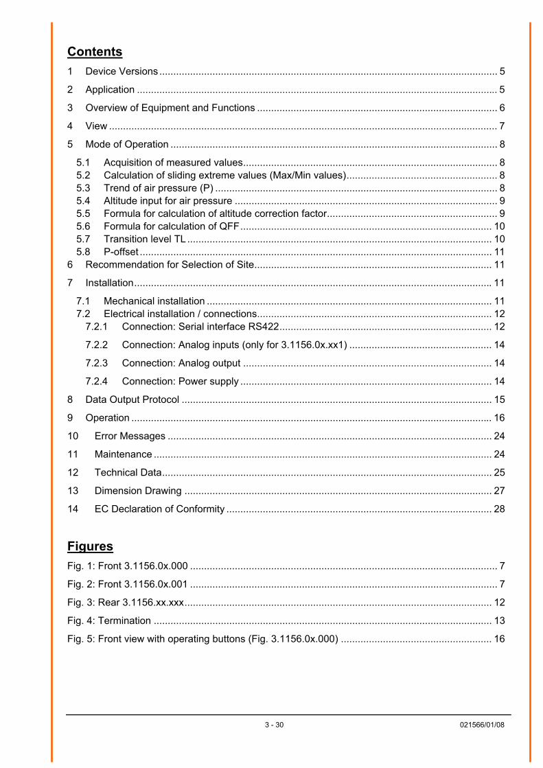
Contents 1 Device Versions ......................................................................................................................... 5
2 Application ................................................................................................................................. 5
3 Overview of Equipment and Functions ...................................................................................... 6
4 View ........................................................................................................................................... 7
5 Mode of Operation ..................................................................................................................... 8
5.1 Acquisition of measured values........................................................................................... 8 5.2 Calculation of sliding extreme values (Max/Min values)...................................................... 8 5.3 Trend of air pressure (P) ..................................................................................................... 8 5.4 Altitude input for air pressure .............................................................................................. 9 5.5 Formula for calculation of altitude correction factor............................................................. 9 5.6 Formula for calculation of QFF.......................................................................................... 10 5.7 Transition level TL ............................................................................................................. 10 5.8 P-offset .............................................................................................................................. 11
6 Recommendation for Selection of Site..................................................................................... 11
7 Installation................................................................................................................................ 11
7.1 Mechanical installation ...................................................................................................... 11 7.2 Electrical installation / connections.................................................................................... 12
7.2.1 Connection: Serial interface RS422............................................................................ 12
7.2.2 Connection: Analog inputs (only for 3.1156.0x.xx1) ................................................... 14
7.2.3 Connection: Analog output ......................................................................................... 14
7.2.4 Connection: Power supply .......................................................................................... 14
8 Data Output Protocol ............................................................................................................... 15
9 Operation ................................................................................................................................. 16
10 Error Messages .................................................................................................................... 24
11 Maintenance ......................................................................................................................... 24
12 Technical Data...................................................................................................................... 25
13 Dimension Drawing .............................................................................................................. 27
14 EC Declaration of Conformity ............................................................................................... 28
Figures Fig. 1: Front 3.1156.0x.000 .............................................................................................................. 7
Fig. 2: Front 3.1156.0x.001 .............................................................................................................. 7
Fig. 3: Rear 3.1156.xx.xxx.............................................................................................................. 12
Fig. 4: Termination ......................................................................................................................... 13
Fig. 5: Front view with operating buttons (Fig. 3.1156.0x.000) ...................................................... 16
4 - 30 021566/01/08
Tables Table 1: Device versions .................................................................................................................. 5
Table 2: Table of operating functions ............................................................................................. 20
Table 3: Display status of MIN & MAX LEDs.................................................................................. 21
Table 4: Device parameters ........................................................................................................... 23
Table 5: Error messages ................................................................................................................ 24
5 - 30 021566/01/08
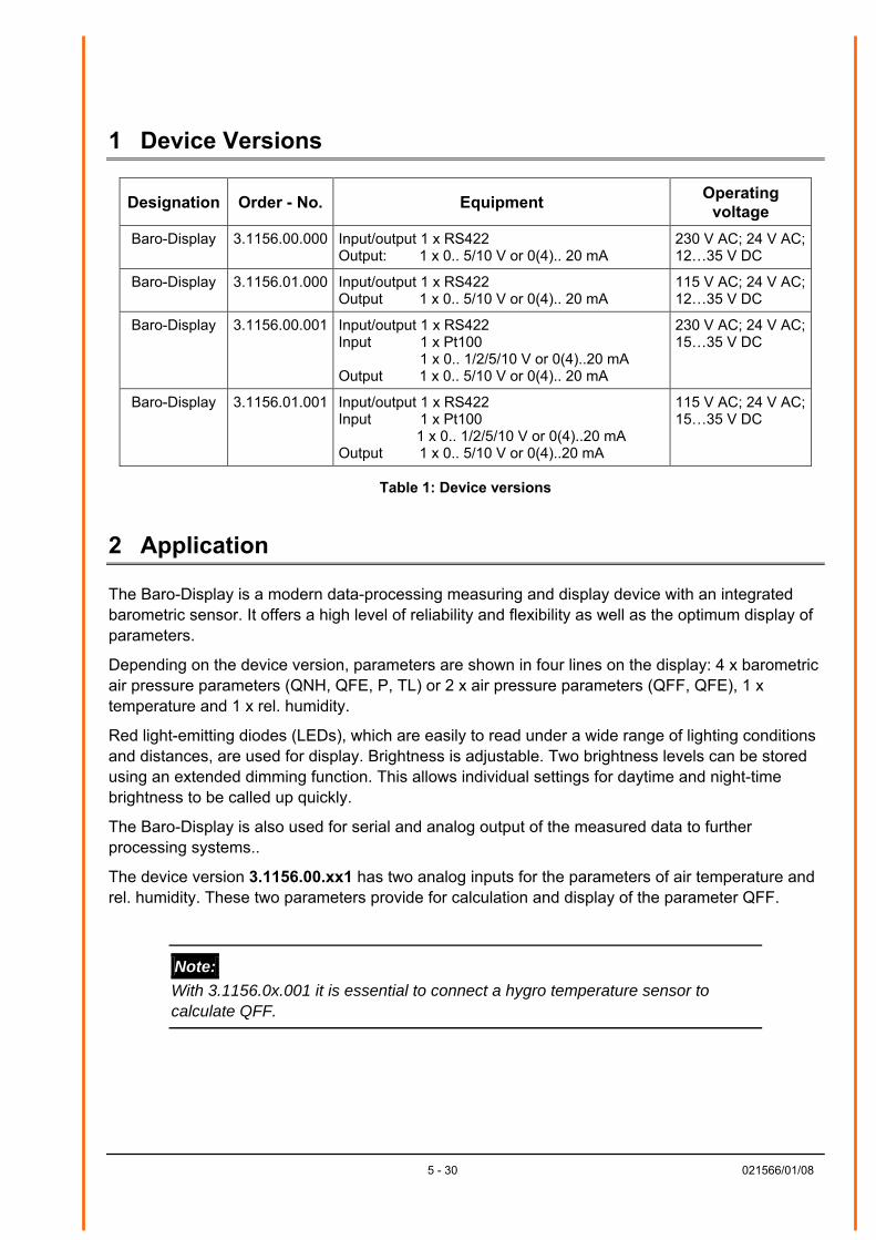
1 Device Versions
Designation Order - No. Equipment Operating voltage
Baro-Display 3.1156.00.000 Input/output 1 x RS422 Output: 1 x 0.. 5/10 V or 0(4).. 20 mA
230 V AC; 24 V AC; 12…35 V DC
Baro-Display 3.1156.01.000 Input/output 1 x RS422 Output 1 x 0.. 5/10 V or 0(4).. 20 mA
115 V AC; 24 V AC; 12…35 V DC
Baro-Display 3.1156.00.001 Input/output 1 x RS422 Input 1 x Pt100 1 x 0.. 1/2/5/10 V or 0(4)..20 mA Output 1 x 0.. 5/10 V or 0(4).. 20 mA
230 V AC; 24 V AC; 15…35 V DC
Baro-Display 3.1156.01.001 Input/output 1 x RS422 Input 1 x Pt100 1 x 0.. 1/2/5/10 V or 0(4)..20 mA Output 1 x 0.. 5/10 V or 0(4)..20 mA
115 V AC; 24 V AC; 15…35 V DC
Table 1: Device versions
2 Application
The Baro-Display is a modern data-processing measuring and display device with an integrated barometric sensor. It offers a high level of reliability and flexibility as well as the optimum display of parameters.
Depending on the device version, parameters are shown in four lines on the display: 4 x barometric air pressure parameters (QNH, QFE, P, TL) or 2 x air pressure parameters (QFF, QFE), 1 x temperature and 1 x rel. humidity.
Red light-emitting diodes (LEDs), which are easily to read under a wide range of lighting conditions and distances, are used for display. Brightness is adjustable. Two brightness levels can be stored using an extended dimming function. This allows individual settings for daytime and night-time brightness to be called up quickly.
The Baro-Display is also used for serial and analog output of the measured data to further processing systems..
The device version 3.1156.00.xx1 has two analog inputs for the parameters of air temperature and rel. humidity. These two parameters provide for calculation and display of the parameter QFF.
Note: With 3.1156.0x.001 it is essential to connect a hygro temperature sensor to calculate QFF.
6 - 30 021566/01/08
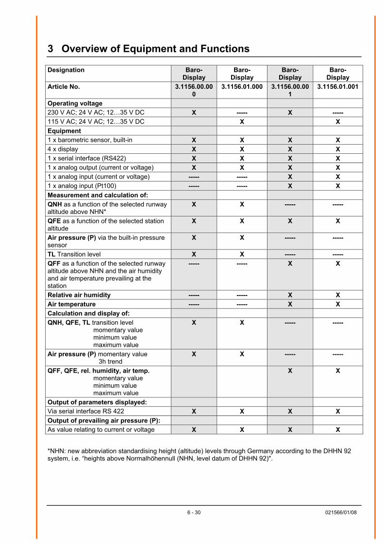
3 Overview of Equipment and Functions
Designation Baro- Display
Baro- Display
Baro- Display
Baro- Display
Article No. 3.1156.00.000
3.1156.01.000 3.1156.00.001
3.1156.01.001
Operating voltage 230 V AC; 24 V AC; 12…35 V DC X ----- X ----- 115 V AC; 24 V AC; 12…35 V DC X X Equipment 1 x barometric sensor, built-in X X X X 4 x display X X X X 1 x serial interface (RS422) X X X X 1 x analog output (current or voltage) X X X X 1 x analog input (current or voltage) ----- ----- X X 1 x analog input (Pt100) ----- ----- X X Measurement and calculation of: QNH as a function of the selected runway altitude above NHN*
X X ----- -----
QFE as a function of the selected station altitude
X X X X
Air pressure (P) via the built-in pressure sensor
X X ----- -----
TL Transition level X X ----- ----- QFF as a function of the selected runway altitude above NHN and the air humidity and air temperature prevailing at the station
----- ----- X X
Relative air humidity ----- ----- X X Air temperature ----- ----- X X Calculation and display of: QNH, QFE, TL transition level momentary value minimum value maximum value
X X ----- -----
Air pressure (P) momentary value 3h trend
X X ----- -----
QFF, QFE, rel. humidity, air temp. momentary value minimum value maximum value
X X
Output of parameters displayed: Via serial interface RS 422 X X X X Output of prevailing air pressure (P): As value relating to current or voltage X X X X *NHN: new abbreviation standardising height (altitude) levels through Germany according to the DHHN 92 system, i.e. “heights above Normalhöhennull (NHN, level datum of DHHN 92)".
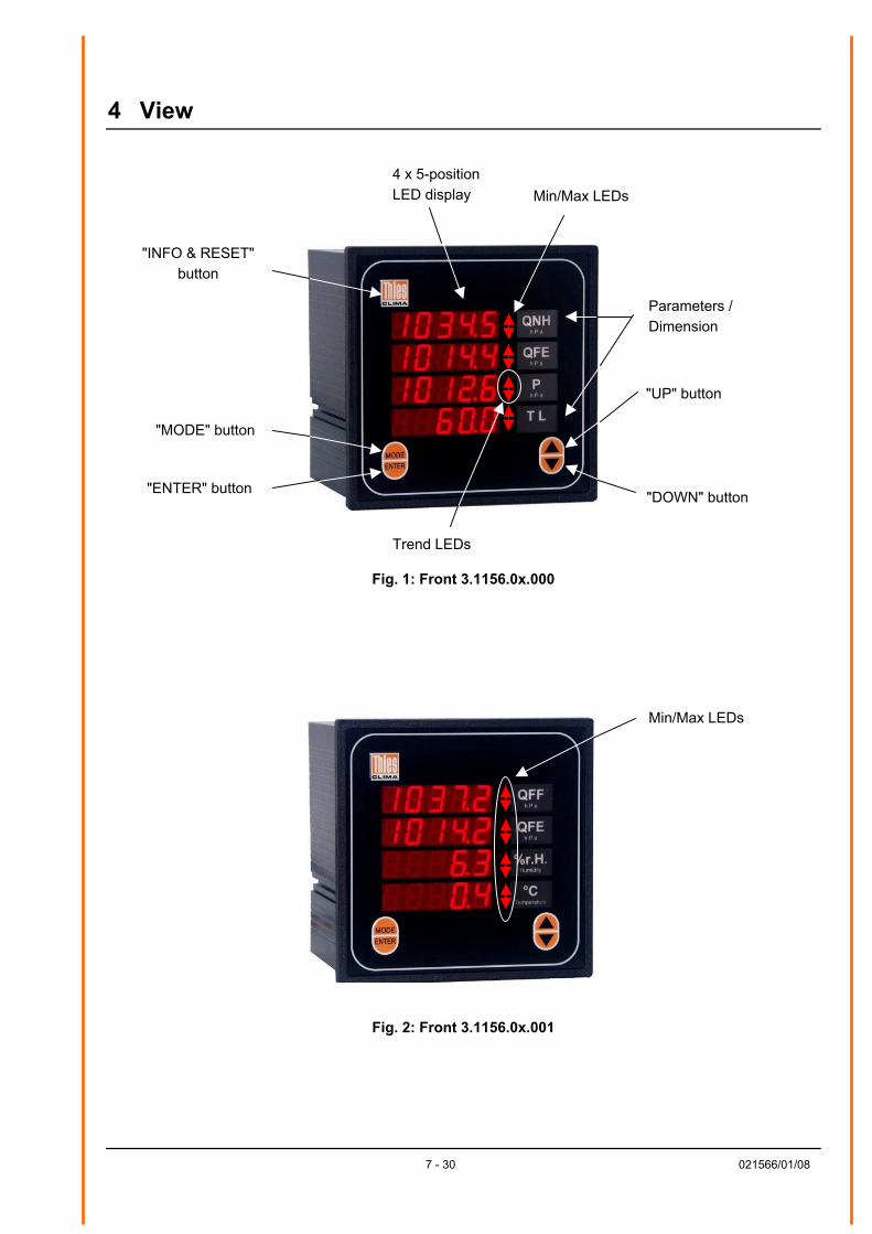
4 View
4 x 5-positionLED display
"DOWN" button
"UP" button
Parameters /Dimension
Min/Max LEDs
"INFO & RESET" button
"MODE" button
"ENTER" button
Trend LEDs
Fig. 1: Front 3.1156.0x.000
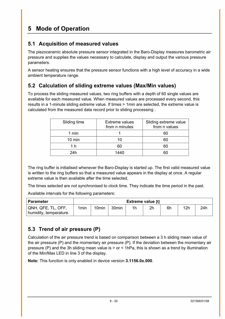
Min/Max LEDs
Fig. 2: Front 3.1156.0x.001
7 - 30 021566/01/08
8 - 30 021566/01/08
5 Mode of Operation
5.1 Acquisition of measured values The piezoceramic absolute pressure sensor integrated in the Baro-Display measures barometric air pressure and supplies the values necessary to calculate, display and output the various pressure parameters.
A sensor heating ensures that the pressure sensor functions with a high level of accuracy in a wide ambient temperature range.
5.2 Calculation of sliding extreme values (Max/Min values) To process the sliding measured values, two ring buffers with a depth of 60 single values are available for each measured value. When measured values are processed every second, this results in a 1-minute sliding extreme value. If times > 1min are selected, the extreme value is calculated from the measured data record prior to sliding processing .
Sliding time Extreme values from n minutes
Sliding extreme value from n values
1 min 1 60 10 min 10 60
1 h 60 60 24h 1440 60
The ring buffer is initialised whenever the Baro-Display is started up. The first valid measured value is written to the ring buffers so that a measured value appears in the display at once. A regular extreme value is then available after the time selected.
The times selected are not synchronised to clock time. They indicate the time period in the past.
Available intervals for the following parameters:
Parameter Extreme value [t] QNH, QFE, TL, OFF, humidity, temperature.
1min 10min 30min 1h 2h 6h 12h 24h
5.3 Trend of air pressure (P) Calculation of the air pressure trend is based on comparison between a 3 h sliding mean value of the air pressure (P) and the momentary air pressure (P). If the deviation between the momentary air pressure (P) and the 3h sliding mean value is > or < 1hPa, this is shown as a trend by illumination of the Min/Max LED in line 3 of the display.
Note: This function is only enabled in device version 3.1156.0x.000.
5.4 Altitude input for air pressure The following parameters can be corrected by inputting the altitude:
QFE 0-100m Default = 0m
QNH 0-3000m Default = 0m 3.1156.0x.000
QFF 0-3000m Default = 0m 3.1156.0x.001
Inputting of the altitude always relates to the station altitude (altitude of Baro-Display above NHN).
The buttons on the front of the device are used to input the altitude. See item 5 in section 10 for a description of how to input the altitude of the station.
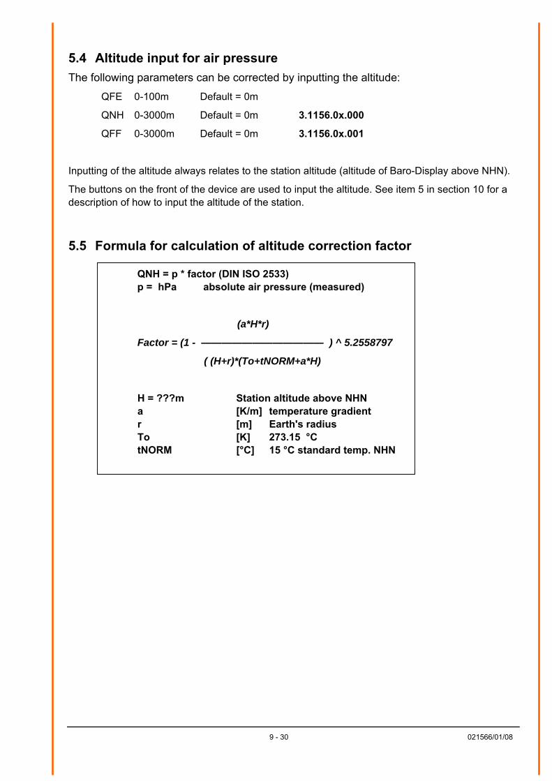
5.5 Formula for calculation of altitude correction factor
QNH = p * factor (DIN ISO 2533) p = hPa absolute air pressure (measured)
(a*H*r)
Factor = (1 - ———————————— ) ^ 5.2558797
( (H+r)*(To+tNORM+a*H)
H = ???m Station altitude above NHN a [K/m] temperature gradient r [m] Earth's radius To [K] 273.15 °C tNORM [°C] 15 °C standard temp. NHN
9 - 30 021566/01/08
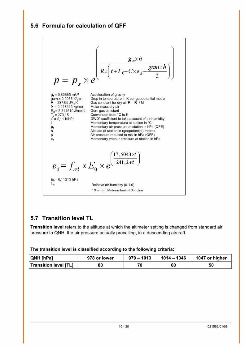
5.6 Formula for calculation of QFF
Relative air humidity (0-1.0) * German Meteorological Service
Acceleration of gravity Drop in temperature in K per geopotential metre Gas constant for dry air R = R / M Molar mass dry air Gen. gas constant Conversion from °C to K DWD* coefficient to take account of air humidity Momentary temperature at station in °C Momentary air pressure at station in hPa (QFE) Altitude of station in (geopotential) metres Air pressure reduced to msl in hPa (QFF) Momentary vapour pressure at station in hPa
5.7 Transition level TL Transition level refers to the altitude at which the altimeter setting is changed from standard air pressure to QNH, the air pressure actually prevailing, in a descending aircraft.
The transition level is classified according to the following criteria:
QNH [hPa] 978 or lower 979 – 1013 1014 – 1046 1047 or higher Transition level [TL] 80 70 60 50
10 - 30 021566/01/08
11 - 30 021566/01/08
5.8 P-offset P-offset is used to calibrate the Baro-Display.
The air pressure displayed can be corrected using the buttons on the front. A correction value is calculated from the difference between the reference pressure input and the internally measured absolute pressure (P) and subsequently saved.
As the absolute pressure (P) is not displayed directly with model 3.1156.0x.xx1, the QFE value has to be set to zero before calibration. The level for the QFE value should then be re-adjusted.
6 Recommendation for Selection of Site
The device is designed for indoor installation. When used outdoors, an additional external housing including the appropriate type of protection is required.
Note: Pressure equalisation in relation to the atmospheric air pressure must be possible at the installation site of the Baro-Display.
Note: When selecting the installation site, please take note of the operating temperature range.
7 Installation
Note: The device should only be fitted and connected by qualified technicians. The general engineering regulations and provisions and standards applicable in each case must be observed.
7.1 Mechanical installation The display is designed for installation in a control panel. The necessary opening in the control panel must measure 138 x 138 mm. The scope of supply includes two fixing brackets. After the device has been inserted in the control panel, the fixing brackets are slid into the housing at the rear and screwed into place.
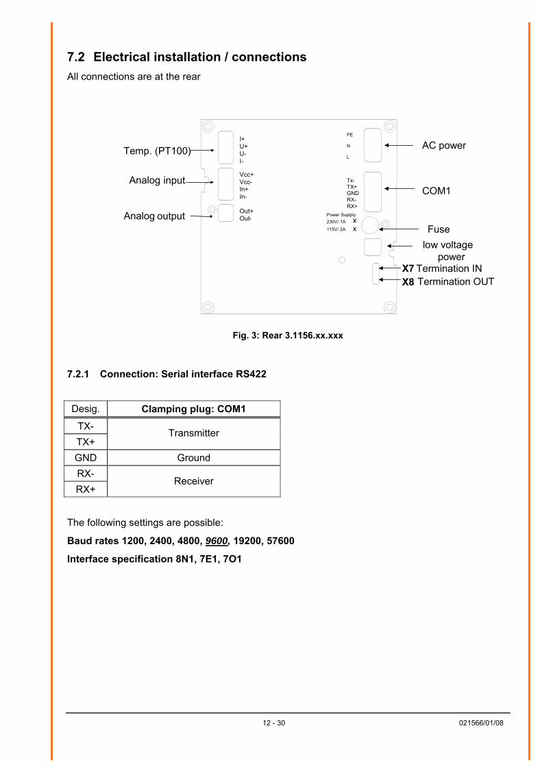
7.2 Electrical installation / connections All connections are at the rear
7.2.1 Co
Desig.
TX- TX+ GND RX- RX+
The follow
Baud rate
Interface s
12 - 30 021566/01/08
AC power
Tx-TX+GNDRX-RX+
PE
N
L
COM1
Fuse
low voltage power
X7 Termination IN X8 Termination OUT
I+ U+ U- I-
Vcc+ Vcc- In+ In-
Out+ Out-
Temp. (PT100)
Analog input
Analog output Power Suplply230V/ 1A 115V/ 2A
xx
Fig. 3: Rear 3.1156.xx.xxx
nnection: Serial interface RS422
Clamping plug: COM1
Transmitter
Ground
Receiver
ing settings are possible:
s 1200, 2400, 4800, 9600, 19200, 57600
pecification 8N1, 7E1, 7O1
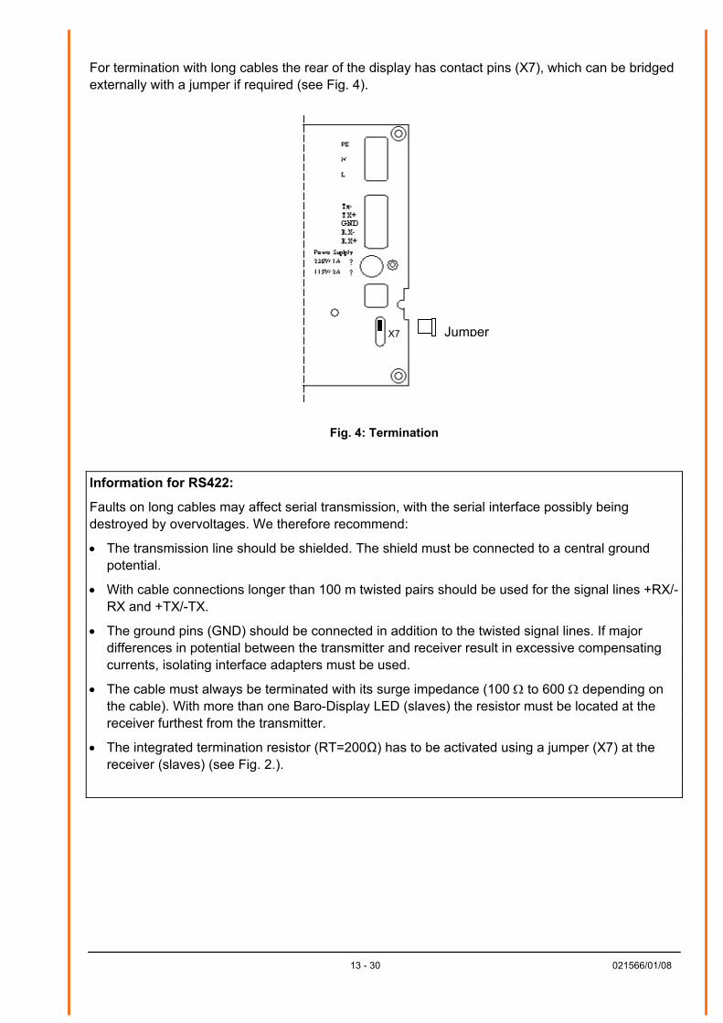
For termination with long cables the rear of the display has contact pins (X7), which can be bridged externally with a jumper if required (see Fig. 4).
X7
Jumper
Fig. 4: Termination
Information for RS422:
Faults on long cables may affect serial transmission, with the serial interface possibly being destroyed by overvoltages. We therefore recommend:
• The transmission line should be shielded. The shield must be connected to a central ground potential.
• With cable connections longer than 100 m twisted pairs should be used for the signal lines +RX/-RX and +TX/-TX.
• The ground pins (GND) should be connected in addition to the twisted signal lines. If major differences in potential between the transmitter and receiver result in excessive compensating currents, isolating interface adapters must be used.
• The cable must always be terminated with its surge impedance (100 Ω to 600 Ω depending on the cable). With more than one Baro-Display LED (slaves) the resistor must be located at the receiver furthest from the transmitter.
• The integrated termination resistor (RT=200Ω) has to be activated using a jumper (X7) at the receiver (slaves) (see Fig. 2.).
13 - 30 021566/01/08
14 - 30 021566/01/08
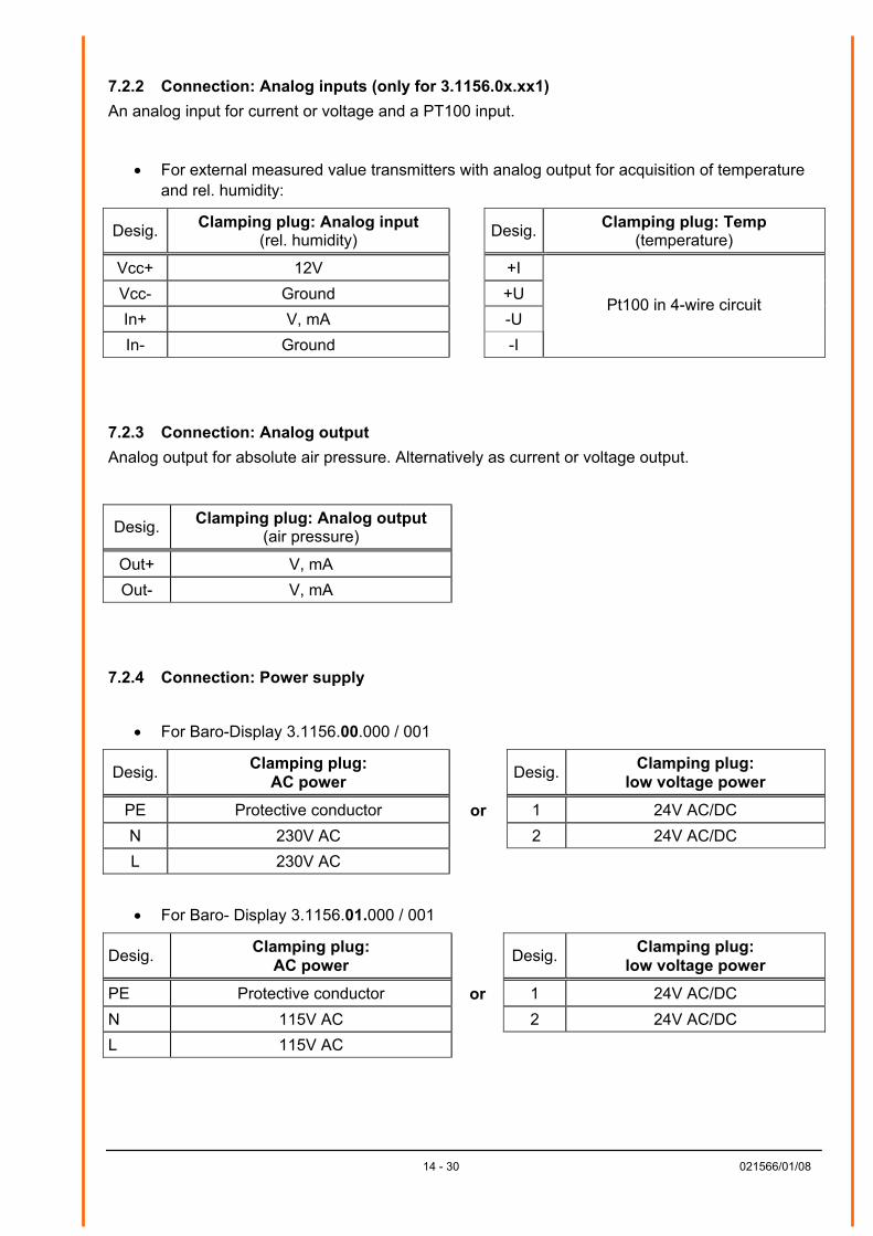
7.2.2 Connection: Analog inputs (only for 3.1156.0x.xx1) An analog input for current or voltage and a PT100 input.
• For external measured value transmitters with analog output for acquisition of temperature and rel. humidity:
Desig. Clamping plug: Analog input (rel. humidity) Desig. Clamping plug: Temp
(temperature)
Vcc+ 12V +I Vcc- Ground +U In+ V, mA -U In- Ground -I
Pt100 in 4-wire circuit
7.2.3 Connection: Analog output Analog output for absolute air pressure. Alternatively as current or voltage output.
Desig. Clamping plug: Analog output (air pressure)
Out+ V, mA Out- V, mA
7.2.4 Connection: Power supply
• For Baro-Display 3.1156.00.000 / 001
Desig. Clamping plug: AC power Desig. Clamping plug:
low voltage power
PE Protective conductor or 1 24V AC/DC N 230V AC 2 24V AC/DC L 230V AC
• For Baro- Display 3.1156.01.000 / 001
Desig. Clamping plug: AC power Desig. Clamping plug:
low voltage power
PE Protective conductor or 1 24V AC/DC N 115V AC 2 24V AC/DC L 115V AC
15 - 30 021566/01/08
8 Data Output Protocol
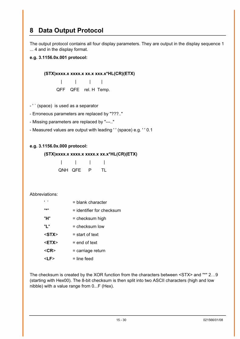
The output protocol contains all four display parameters. They are output in the display sequence 1 ... 4 and in the display format.
e.g. 3.1156.0x.001 protocol:
(STX)xxxx.x xxxx.x xx.x xxx.x*HL(CR)(ETX)
| | | |
QFF QFE rel. H Temp.
- ' ` (space) is used as a separator
- Erroneous parameters are replaced by "???.."
- Missing parameters are replaced by "---.."
- Measured values are output with leading ' ' (space) e.g. ' ' 0.1
e.g. 3.1156.0x.000 protocol:
(STX)xxxx.x xxxx.x xxxx.x xx.x*HL(CR)(ETX)
| | | |
QNH QFE P TL
Abbreviations:
' ’ = blank character
"*" = identifier for checksum
"H" = checksum high
"L" = checksum low
<STX> = start of text
<ETX> = end of text
<CR> = carriage return
<LF> = line feed
The checksum is created by the XOR function from the characters between <STX> and "*" 2…9 (starting with Hex00). The 8-bit checksum is then split into two ASCII characters (high and low nibble) with a value range from 0...F (Hex).
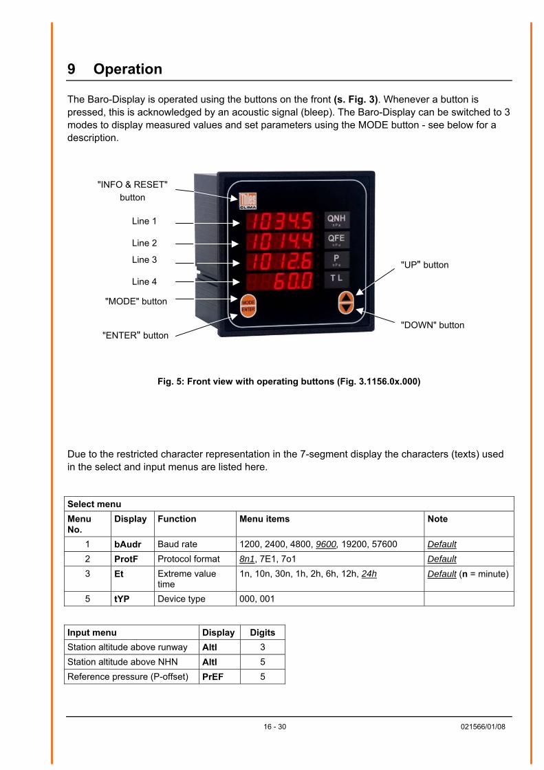
9 Operation
The Baro-Display is operated using the buttons on the front (s. Fig. 3). Whenever a button is pressed, this is acknowledged by an acoustic signal (bleep). The Baro-Display can be switched to 3 modes to display measured values and set parameters using the MODE button - see below for a description.
"INFO & RESET"
button
"MODE" button
"ENTER" button "DOWN" button
"UP" button
Line 4
Line 3
Line 2
Line 1
Fig. 5: Front view with operating buttons (Fig. 3.1156.0x.000)
Due to the restricted character representation in the 7-segment display the characters (texts) used in the select and input menus are listed here.
Select menu Menu No.
Display Function Menu items Note
1 bAudr Baud rate 1200, 2400, 4800, 9600, 19200, 57600 Default2 ProtF Protocol format 8n1, 7E1, 7o1 Default3 Et Extreme value
time 1n, 10n, 30n, 1h, 2h, 6h, 12h, 24h Default (n = minute)
5 tYP Device type 000, 001
Input menu Display Digits Station altitude above runway AltI 3 Station altitude above NHN AltI 5 Reference pressure (P-offset) PrEF 5
16 - 30 021566/01/08

Menu structure:
The Baro-Display has 3 operating modes
Mode 1
Select menus
Mode 2 Edit menus
Mode 0
Display mode
Mode 0 (display mode ):
Whenever the device is restarted, the display automatically switches to operating mode 0 (Display measured values) and line 0. Line 0 is an imaginary line. The brightness level of the display lines can be selected in this mode.
The "MODE" button can be used to move to the next line. Indicated by the flashing MIN/MAX LEDs in each line.
The "" (UP) button and "" (DOWN) button can be used here to select display of the Mom, Min, Max values.
When the imaginary line 5 is reached, the display of measured values is switched off and the pressure sensor temperature is shown in lines 1 and 2 , e.g.
49.4
tEnP
Overview of functions available in Mode 0
Line 0
Line 1
Line 2
Line 3 *
Line 4
Line 5
Dimming functions
Mom, Min, Max
Mom, Min, Max
Mom, Min, Max
Mom, Min, Max
Sensor temperature
*Special function in line 3:
Device version 3.1156.0x.000: Min/Max LED off = absolute air pressure Min/Max LED on = air pressure trend Device version 3.1156.0x.001: Min/Max LED off = momentary value rel. humidity Min/Max LED on = Min/Max rel. humidity
17 - 30 021566/01/08
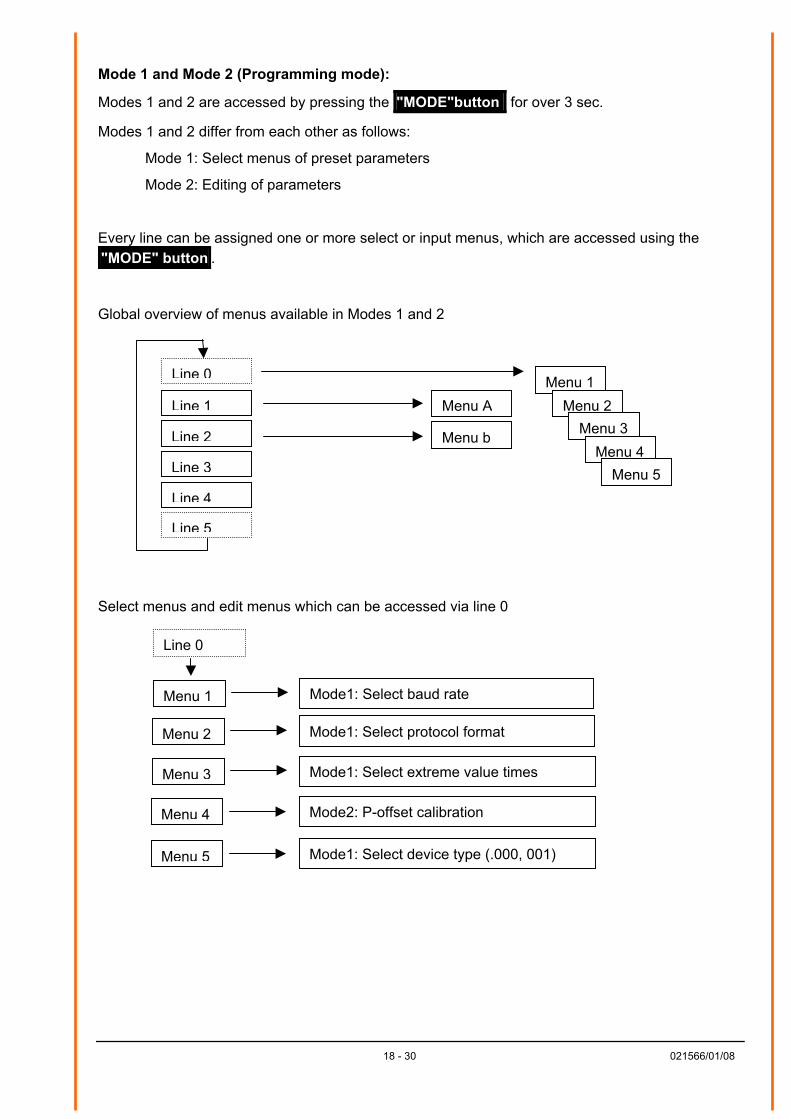
Mode 1 and Mode 2 (Programming mode):
Modes 1 and 2 are accessed by pressing the "MODE"button for over 3 sec.
Modes 1 and 2 differ from each other as follows:
Mode 1: Select menus of preset parameters
Mode 2: Editing of parameters
Every line can be assigned one or more select or input menus, which are accessed using the "MODE" button .
Global overview of menus available in Modes 1 and 2
Line 0
Line 1
Line 2
Line 3
Line 4
Line 5
Menu 1 Menu 2
Menu 3 Menu 4
Menu b
Menu A
Menu 5
Select menus and edit menus which can be accessed via line 0
Menu 1 Mode1: Select baud rate
Menu 2 Mode1: Select protocol format
Menu 3 Mode1: Select extreme value times
Menu 4
Menu 5
Line 0
Mode2: P-offset calibration
Mode1: Select device type (.000, 001)
18 - 30 021566/01/08
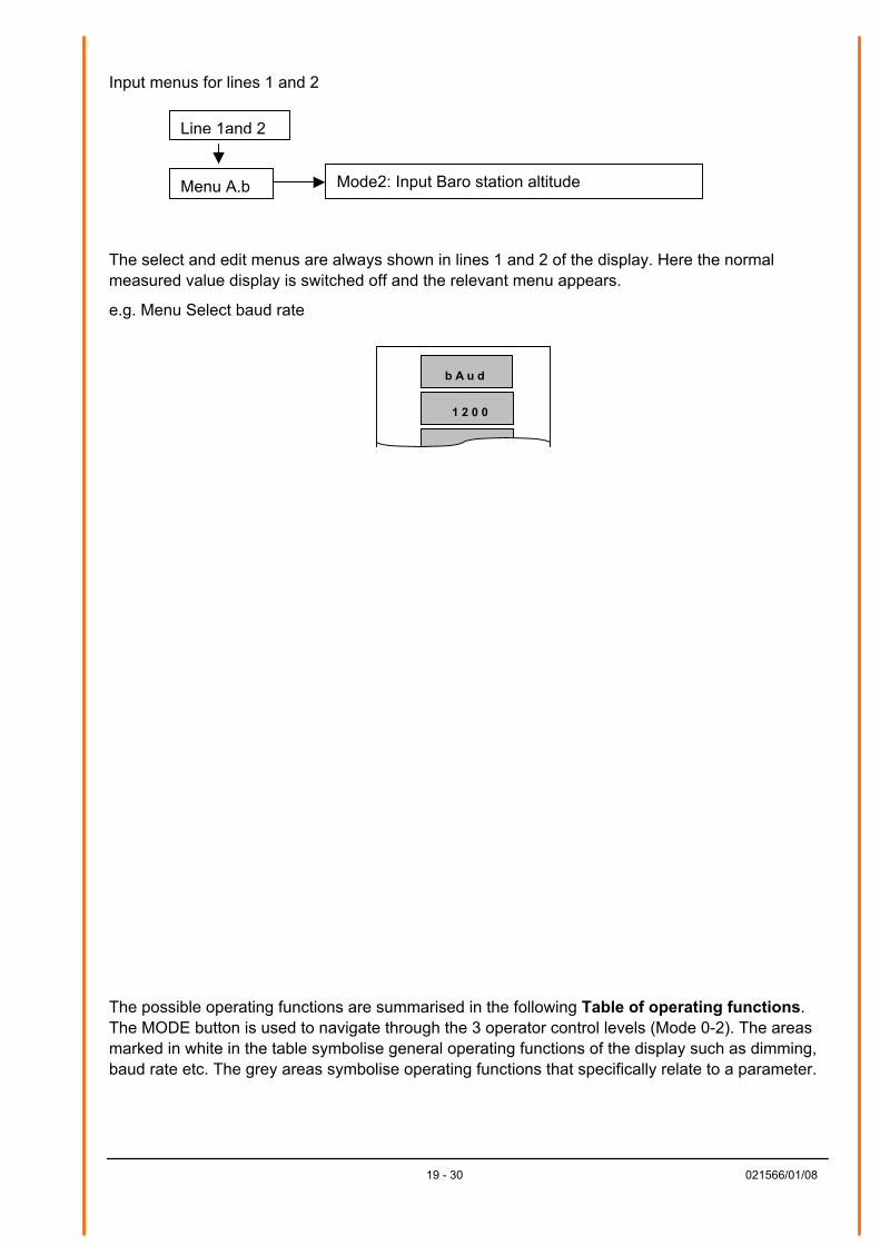
Input menus for lines 1 and 2
Menu A,b
Line 1and 2
Mode2: Input Baro station altitude
The select and edit menus are always shown in lines 1 and 2 of the display. Here the normal measured value display is switched off and the relevant menu appears.
e.g. Menu Select baud rate
1 2 0 0
b A u d
The possible operating functions are summarised in the following Table of operating functions. The MODE button is used to navigate through the 3 operator control levels (Mode 0-2). The areas marked in white in the table symbolise general operating functions of the display such as dimming, baud rate etc. The grey areas symbolise operating functions that specifically relate to a parameter.
19 - 30 021566/01/08
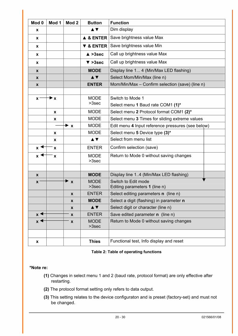
Mod 0 Mod 1 Mod 2 Button Function x Dim display
x & ENTER Save brightness value Max
x & ENTER Save brightness value Min
x >3sec Call up brightness value Max
x >3sec Call up brightness value Max
x MODE Display line 1... 4 (Min/Max LED flashing) x Select Mom/Min/Max (line n) x ENTER Mom/Min/Max – Confirm selection (save) (line n)
x x MODE >3sec
Switch to Mode 1 Select menu 1 Baud rate COM1 (1)*
x MODE Select menu 2 Protocol format COM1 (2)* x MODE Select menu 3 Times for sliding extreme values x MODE Edit menu 4 Input reference pressures (see below) x MODE Select menu 5 Device type (3)* x Select from menu list
x x ENTER Confirm selection (save)
x x MODE >3sec
Return to Mode 0 without saving changes
x MODE Display line 1..4 (Min/Max LED flashing) x x MODE
>3sec Switch to Edit mode Editing parameters 1 (line n)
x ENTER Select editing parameters n (line n) x MODE Select a digit (flashing) in parameter n x Select digit or character (line n)
x x ENTER Save edited parameter n (line n) x x MODE
>3sec Return to Mode 0 without saving changes
x Thies Functional test, Info display and reset
Table 2: Table of operating functions
*Note re:
(1) Changes in select menu 1 and 2 (baud rate, protocol format) are only effective after restarting.
(2) The protocol format setting only refers to data output.
(3) This setting relates to the device configuraton and is preset (factory-set) and must not be changed.
20 - 30 021566/01/08
21 - 30 021566/01/08
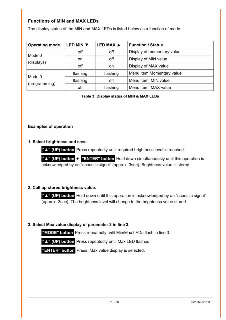
Functions of MIN and MAX LEDs The display status of the MIN and MAX LEDs is listed below as a function of mode:
Operating mode LED MIN LED MAX Function / Status off off Display of momentary value
on off Display of MIN value Mode 0 (displays)
off on Display of MAX value
flashing flashing Menu item Momentary value
flashing off Menu item MIN value Mode 0 (programming)
off flashing Menu item MAX value
Table 3: Display status of MIN & MAX LEDs
Examples of operation 1. Select brightness and save.
"" (UP) button Press repeatedly until required brightness level is reached.
"" (UP) button + "ENTER" button Hold down simultaneously until this operation is acknowledged by an "acoustic signal" (approx. 3sec). Brightness value is stored.
2. Call up stored brightness value.
"" (UP) button Hold down until this operation is acknowledged by an "acoustic signal" (approx. 3sec). The brightness level will change to the brightness value stored.
3. Select Max value display of parameter 3 in line 3.
"MODE" button Press repeatedly until Min/Max LEDs flash in line 3.
"" (UP) button Press repeatedly until Max LED flashes.
"ENTER" button Press. Max value display is selected.
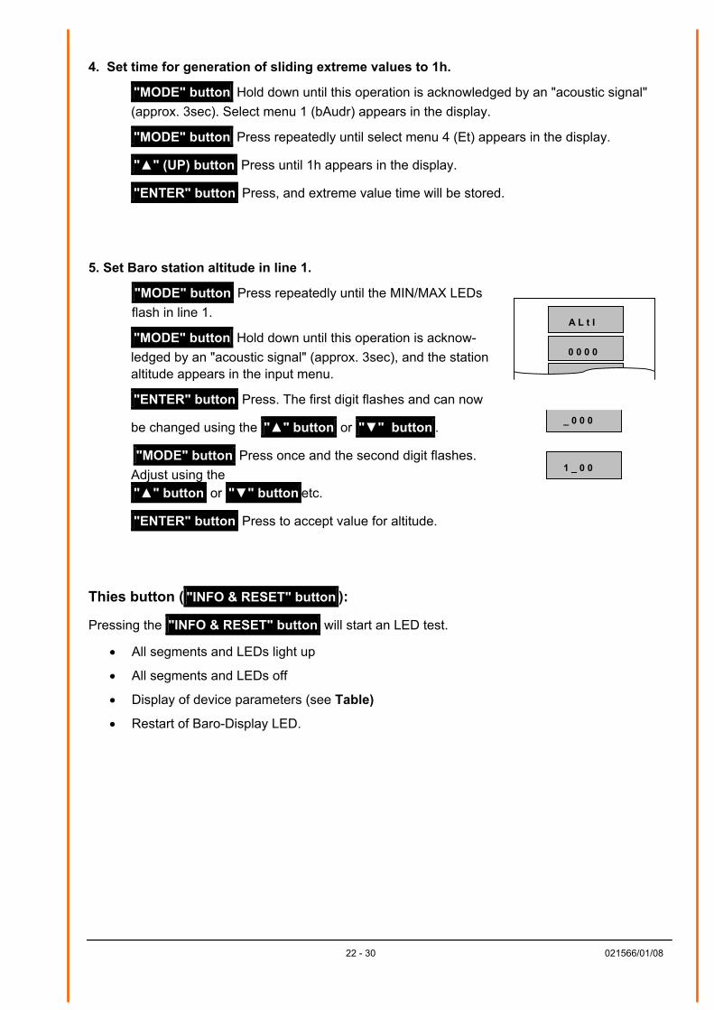
4. Set time for generation of sliding extreme values to 1h.
"MODE" button Hold down until this operation is acknowledged by an "acoustic signal" (approx. 3sec). Select menu 1 (bAudr) appears in the display.
"MODE" button Press repeatedly until select menu 4 (Et) appears in the display.
"" (UP) button Press until 1h appears in the display.
"ENTER" button Press, and extreme value time will be stored.
5. Set Baro station altitude in line 1.
"MODE" button Press repeatedly until the MIN/MAX LEDs flash in line 1.
0 0 0 0
A L t I
"MODE" button Hold down until this operation is acknow- ledged by an "acoustic signal" (approx. 3sec), and the station altitude appears in the input menu.
"ENTER" button Press. The first digit flashes and can now
be changed using the "" button or "" button .
"MODE" button Press once and the second digit flashes. Adjust using the "" button or "" button etc.
"ENTER" button Press to accept value for altitude.
Thies button ( "INFO & RESET" button ):
Pressing the "INFO & RESET" button will start an LED test.
• All segments and LEDs light up
• All segments and LEDs off
• Display of device parameters (see Table)
• Restart of Baro-Display LED.
22 - 30
_ 0 0 0
1 _ 0 0021566/01/08
23 - 30 021566/01/08
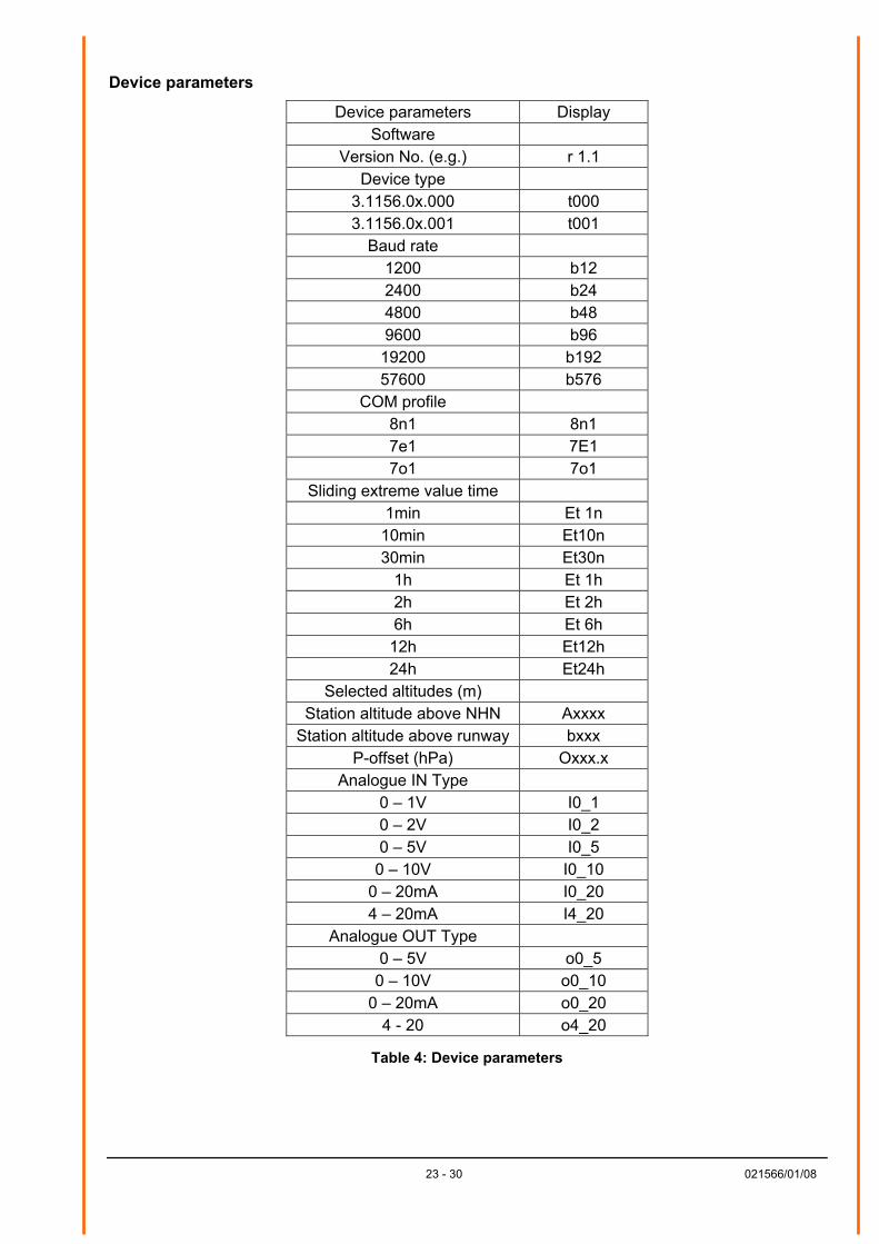
Device parameters
Device parameters Display Software
Version No. (e.g.) r 1.1 Device type
3.1156.0x.000 t000 3.1156.0x.001 t001
Baud rate 1200 b12 2400 b24 4800 b48 9600 b96
19200 b192 57600 b576
COM profile 8n1 8n1 7e1 7E1 7o1 7o1
Sliding extreme value time 1min Et 1n
10min Et10n 30min Et30n
1h Et 1h 2h Et 2h 6h Et 6h
12h Et12h 24h Et24h
Selected altitudes (m) Station altitude above NHN Axxxx
Station altitude above runway bxxx P-offset (hPa) Oxxx.x
Analogue IN Type 0 – 1V I0_1 0 – 2V I0_2 0 – 5V I0_5
0 – 10V I0_10 0 – 20mA I0_20 4 – 20mA I4_20
Analogue OUT Type 0 – 5V o0_5
0 – 10V o0_10 0 – 20mA o0_20
4 - 20 o4_20
Table 4: Device parameters
24 - 30 021566/01/08
10 Error Messages
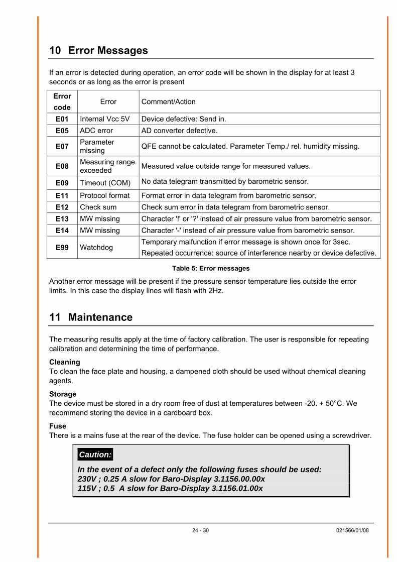
If an error is detected during operation, an error code will be shown in the display for at least 3 seconds or as long as the error is present
Error code
Error Comment/Action
E01 Internal Vcc 5V Device defective: Send in. E05 ADC error AD converter defective.
E07 Parameter missing QFE cannot be calculated. Parameter Temp./ rel. humidity missing.
E08 Measuring range exceeded Measured value outside range for measured values.
E09 Timeout (COM) No data telegram transmitted by barometric sensor.
E11 Protocol format Format error in data telegram from barometric sensor. E12 Check sum Check sum error in data telegram from barometric sensor. E13 MW missing Character '!' or '?' instead of air pressure value from barometric sensor. E14 MW missing Character '-' instead of air pressure value from barometric sensor.
E99 Watchdog Temporary malfunction if error message is shown once for 3sec. Repeated occurrence: source of interference nearby or device defective.
Table 5: Error messages
Another error message will be present if the pressure sensor temperature lies outside the error limits. In this case the display lines will flash with 2Hz.
11 Maintenance
The measuring results apply at the time of factory calibration. The user is responsible for repeating calibration and determining the time of performance.
Cleaning To clean the face plate and housing, a dampened cloth should be used without chemical cleaning agents.
Storage The device must be stored in a dry room free of dust at temperatures between -20. + 50°C. We recommend storing the device in a cardboard box.
Fuse There is a mains fuse at the rear of the device. The fuse holder can be opened using a screwdriver.
Caution:
In the event of a defect only the following fuses should be used: 230V ; 0.25 A slow for Baro-Display 3.1156.00.00x 115V ; 0.5 A slow for Baro-Display 3.1156.01.00x
25 - 30 021566/01/08
12 Technical Data
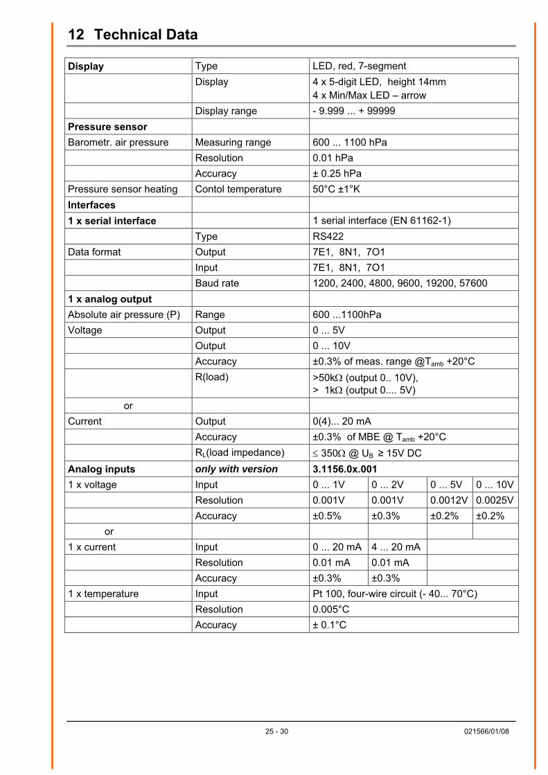
Display Type LED, red, 7-segment Display 4 x 5-digit LED, height 14mm
4 x Min/Max LED – arrow Display range - 9.999 ... + 99999 Pressure sensor Barometr. air pressure Measuring range 600 ... 1100 hPa Resolution 0.01 hPa Accuracy ± 0.25 hPa Pressure sensor heating Contol temperature 50°C ±1°K Interfaces 1 x serial interface 1 serial interface (EN 61162-1) Type RS422 Data format Output 7E1, 8N1, 7O1 Input 7E1, 8N1, 7O1 Baud rate 1200, 2400, 4800, 9600, 19200, 57600 1 x analog output Absolute air pressure (P) Range 600 ...1100hPa Voltage Output 0 ... 5V Output 0 ... 10V Accuracy ±0.3% of meas. range @Tamb +20°C R(load) >50kΩ (output 0.. 10V),
> 1kΩ (output 0.... 5V) or
Current Output 0(4)... 20 mA Accuracy ±0.3% of MBE @ Tamb +20°C RL(load impedance) ≤ 350Ω @ UB ≥ 15V DC Analog inputs only with version 3.1156.0x.001 1 x voltage Input 0 ... 1V 0 ... 2V 0 ... 5V 0 ... 10V Resolution 0.001V 0.001V 0.0012V 0.0025V Accuracy ±0.5% ±0.3% ±0.2% ±0.2% or 1 x current Input 0 ... 20 mA 4 ... 20 mA Resolution 0.01 mA 0.01 mA Accuracy ±0.3% ±0.3% 1 x temperature Input Pt 100, four-wire circuit (- 40... 70°C) Resolution 0.005°C Accuracy ± 0.1°C
26 - 30 021566/01/08
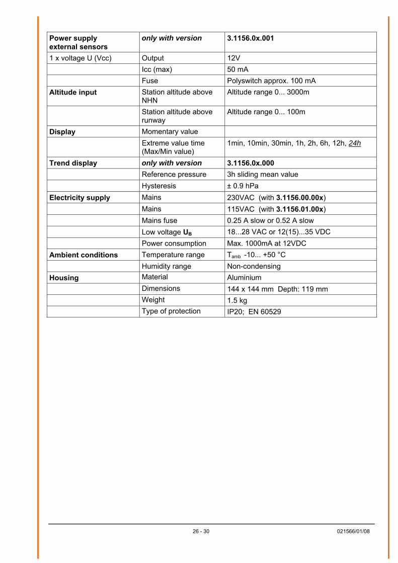
Power supply external sensors
only with version 3.1156.0x.001
1 x voltage U (Vcc) Output 12V Icc (max) 50 mA Fuse Polyswitch approx. 100 mA Altitude input Station altitude above
NHN Altitude range 0... 3000m
Station altitude above runway
Altitude range 0... 100m
Display Momentary value Extreme value time
(Max/Min value) 1min, 10min, 30min, 1h, 2h, 6h, 12h, 24h
Trend display only with version 3.1156.0x.000 Reference pressure 3h sliding mean value Hysteresis ± 0.9 hPa Electricity supply Mains 230VAC (with 3.1156.00.00x) Mains 115VAC (with 3.1156.01.00x) Mains fuse 0.25 A slow or 0.52 A slow Low voltage UB 18...28 VAC or 12(15)...35 VDC Power consumption Max. 1000mA at 12VDC Ambient conditions Temperature range Tamb -10... +50 °C Humidity range Non-condensing Housing Material Aluminium Dimensions 144 x 144 mm Depth: 119 mm Weight 1.5 kg Type of protection IP20; EN 60529
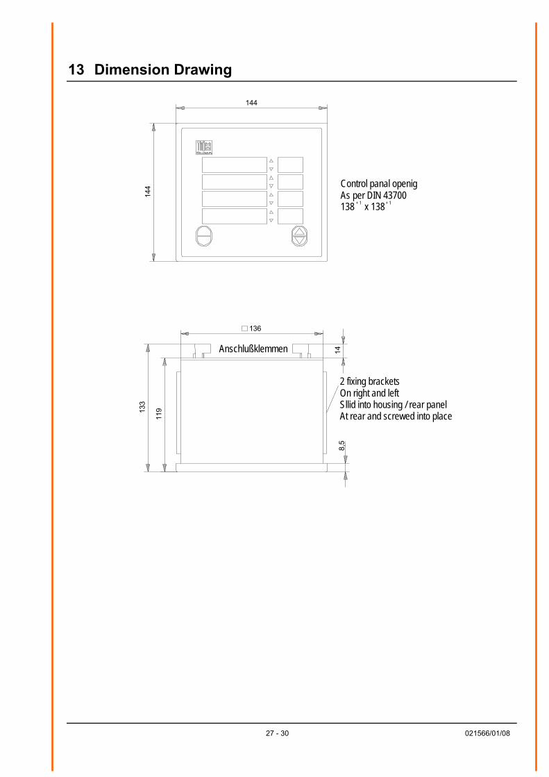
13 Dimension Drawing
144
144 Control panal openig
As per DIN 43700 138 + 1 x 138 + 1
136
119
Anschlußklemmen
133
14
8,5
2 fixing brackets On right and left Sllid into housing / rear panel At rear and screwed into place
27 - 30 021566/01/08
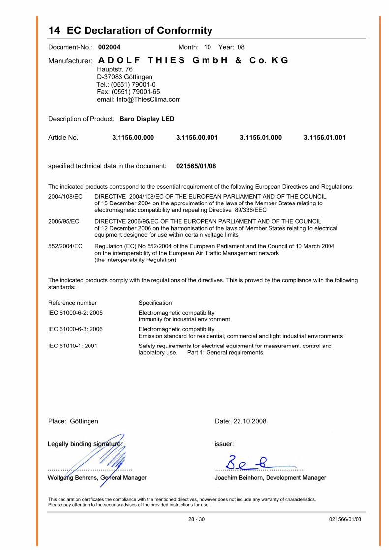
14 EC Declaration of Conformity Document-No.: 002004 Month: 10 Year: 08
Manufacturer: A D O L F T H I E S G m b H & C o. K G Hauptstr. 76 D-37083 Göttingen
Tel.: (0551) 79001-0 Fax: (0551) 79001-65 email: [email protected]
Description of Product: Baro Display LED
Article No. 3.1156.00.000 3.1156.00.001 3.1156.01.000 3.1156.01.001
specified technical data in the document: 021565/01/08 The indicated products correspond to the essential requirement of the following European Directives and Regulations:
2004/108/EC DIRECTIVE 2004/108/EC OF THE EUROPEAN PARLIAMENT AND OF THE COUNCIL of 15 December 2004 on the approximation of the laws of the Member States relating to electromagnetic compatibility and repealing Directive 89/336/EEC
2006/95/EC DIRECTIVE 2006/95/EC OF THE EUROPEAN PARLIAMENT AND OF THE COUNCIL
of 12 December 2006 on the harmonisation of the laws of Member States relating to electrical equipment designed for use within certain voltage limits
552/2004/EC Regulation (EC) No 552/2004 of the European Parliament and the Council of 10 March 2004
on the interoperability of the European Air Traffic Management network (the interoperability Regulation)
The indicated products comply with the regulations of the directives. This is proved by the compliance with the following standards:
Reference number Specification
IEC 61000-6-2: 2005 Electromagnetic compatibility Immunity for industrial environment
IEC 61000-6-3: 2006 Electromagnetic compatibility Emission standard for residential, commercial and light industrial environments
IEC 61010-1: 2001 Safety requirements for electrical equipment for measurement, control and laboratory use. Part 1: General requirements
Place: Göttingen Date: 22.10.2008
This declaration certificates the compliance with the mentioned directives, however does not include any warranty of characteristics. Please pay attention to the security advises of the provided instructions for use.
28 - 30 021566/01/08

29 - 30 021566/01/08

ADOLF THIES GmbH & Co. KG Hauptstraße 76 37083 Göttingen Germany P.O. Box 3536 + 3541 37025 Göttingen Phone +49 551 79001-0 Fax +49 551 79001-65 www.thiesclima.com [email protected]
- Alterations reserved-
30 - 30 021566/01/08