Space Vector Modulation Direct Torque Speed Control Of Induction Motor
8
Procedia Computer Science Procedia Computer Science 00 (2009) 000–000 www.elsevier.com/locate/procedia The 2nd International Conference on Ambient Systems, Networks and Technologies Space Vector Modulation Direct Torque Speed Control Of Induction Motor Mohammed T. Lazim a , Muthanna J. M. Al-khishali b,* , Ahmed Isa. Al-Shawi a,b a Associate Professor, Electrical Eng. Dept., Faculty of Engineering, Philadelphia University, Amman - Jordan b,* Associate Professor, Laser and Optoelectronics Eng. Dept, Faculty of Engineering., Nahrain University Baghdad - Iraq a, b Engineer, Radio Network Planning Supervisor, Korek telecom/ Baghdad office, Baghdad - Iraq ____________________________________________________________________________________________________________________ Abstract Various aspects related to controlling induction motors are investigated. Different control strategies are explored. The direct torque control (DTC) strategy is studied in details and its relation to space vector modulation (SVM) is emphasized. An SVM-based DTC strategy is suggested and a controller design based on this strategy is presented. A Simulink model representing the controller is developed and verified using MATLAB-7. The model exhibits high modularity which makes it suitable for use in different induction motor control systems simulation scenarios. Each block in the model is developed from the very basic capabilities of Simulink which makes the model very suitable for testing and debugging. A modular model for the induction motor based on Krause’s model is developed. This model is used in the simulation instead of the built-in Simulink induction motor block, in order to enable testing of various parts of the induction motor model and to gain a deep insight in machine’s operation. This model is tested separatel y and showed to be working properly through simulating direct AC startup in Simulink. The performance of control is evaluated through simulating the whole system in Simulink and the suggested SVM-based DTC controlling system is shown to be superior to other controlling strategies investigated in the literature. It also shows that the induction motor settles down faster when using the suggested strategy compared to other previously studied strategies. Keywords: Direct Torque Control; Multilevel Drives; Space Vector Modulation; Induction Motor Control ____________________________________________________________________________________________________________________ 1. Introduction With the enormous advances made in semiconductor technology during the last 20 years, the required conditions for developing a proper induction motor drive are present. These conditions can be divided mainly into two groups: The decreasing cost and improved performance in power electronic switching devices. The possibility of implementing complex algorithms in the new microprocessors. However, one precondition had to be made, which was the development of suitable methods to control the speed of induction motors, because in contrast to its mechanical simplicity their complexity regarding their mathematical structure (multivariable and non-linear) is not a trivial matter. It is in this field, that considerable research effort is devoted. The aim is to find even simpler methods of speed control for induction machines. One method, which is popular at the moment, is Direct Torque Control (DTC). It has emerged over the last decade to become one possible alternative to the well-known Vector Control of Induction Machines [1, 2]. Its main characteristic is the good performance, obtaining results as good as the classical vector control but with several advantages based on its simpler structure and control diagram. DTC is said to be one of the future methods of controlling the induction machine in four quadrants [3, 4]. In DTC it is possible to control directly the 4 stator flux and the torque by selecting the appropriate inverter state. This method still requires further research in order to improve the motor's performance, as well as achieve a better behaviour regarding environmental compatibility (Electro Magnetic Interference and energy), that is desired ____________ Corresponding author. Tel +9647902286147, E-mail Address: [email protected]
-
Upload
independent -
Category
Documents
-
view
0 -
download
0
Transcript of Space Vector Modulation Direct Torque Speed Control Of Induction Motor

Procedia Computer Science Procedia Computer Science 00 (2009) 000–000
www.elsevier.com/locate/procedia
The 2nd International Conference on Ambient Systems, Networks and Technologies
Space Vector Modulation Direct Torque Speed Control
Of Induction Motor Mohammed T. Lazim
a, Muthanna J. M. Al-khishali
b,*, Ahmed Isa. Al-Shawi
a,b
a Associate Professor, Electrical Eng. Dept., Faculty of Engineering, Philadelphia University, Amman - Jordan
b,* Associate Professor, Laser and Optoelectronics Eng. Dept, Faculty of Engineering., Nahrain University Baghdad - Iraq a, b Engineer, Radio Network Planning Supervisor, Korek telecom/ Baghdad office, Baghdad - Iraq
____________________________________________________________________________________________________________________
Abstract
Various aspects related to controlling induction motors are investigated. Different control strategies are explored. The direct
torque control (DTC) strategy is studied in details and its relation to space vector modulation (SVM) is emphasized.
An SVM-based DTC strategy is suggested and a controller design based on this strategy is presented. A Simulink model
representing the controller is developed and verified using MATLAB-7. The model exhibits high modularity which makes it
suitable for use in different induction motor control systems simulation scenarios. Each block in the model is developed from
the very basic capabilities of Simulink which makes the model very suitable for testing and debugging.
A modular model for the induction motor based on Krause’s model is developed. This model is used in the simulation instead of
the built-in Simulink induction motor block, in order to enable testing of various parts of the induction motor model and to gain
a deep insight in machine’s operation. This model is tested separately and showed to be working properly through simulating
direct AC startup in Simulink.
The performance of control is evaluated through simulating the whole system in Simulink and the suggested SVM-based DTC
controlling system is shown to be superior to other controlling strategies investigated in the literature. It also shows that the
induction motor settles down faster when using the suggested strategy compared to other previously studied strategies. Keywords: Direct Torque Control; Multilevel Drives; Space Vector Modulation; Induction Motor Control
____________________________________________________________________________________________________________________
1. Introduction
With the enormous advances made in semiconductor technology during the last 20 years, the required
conditions for developing a proper induction motor drive are present. These conditions can be divided mainly into
two groups:
The decreasing cost and improved performance in power electronic switching devices.
The possibility of implementing complex algorithms in the new microprocessors. However, one
precondition had to be made, which was the development of suitable methods to control the speed of induction
motors, because in contrast to its mechanical simplicity their complexity regarding their mathematical structure
(multivariable and non-linear) is not a trivial matter.
It is in this field, that considerable research effort is devoted. The aim is to find even simpler methods of speed
control for induction machines.
One method, which is popular at the moment, is Direct Torque Control (DTC). It has emerged over the last decade
to become one possible alternative to the well-known Vector Control of Induction Machines [1, 2]. Its main
characteristic is the good performance, obtaining results as good as the classical vector control but with several
advantages based on its simpler structure and control diagram.
DTC is said to be one of the future methods of controlling the induction machine in four quadrants [3, 4]. In DTC it
is possible to control directly the 4 stator flux and the torque by selecting the appropriate inverter state. This
method still requires further research in order to improve the motor's performance, as well as achieve a better
behaviour regarding environmental compatibility (Electro Magnetic Interference and energy), that is desired
____________
Corresponding author. Tel +9647902286147, E-mail Address: [email protected]

nowadays for all industrial applications. Its main features are as follows:
Direct control of flux and torque.
Indirect control of stator currents and voltages.
Approximately sinusoidal stator fluxes and stator currents.
High dynamic performance even at standstill
The main advantages of DTC are:
Absence of co-ordinate transforms.
Absence of voltage modulator block, as well as other controllers such as PID for motor flux and torque.
Minimal torque response time, even better than the vector controllers.
However, some disadvantages are also present such as:
Possible problems during starting. It was suggested by [5] that by compensating the stator resistance
voltage drop so that stator flux can be constructed quickly, which makes DTC be applicable for low speed region.
Requirement of torque and flux estimators, implying the consequent parameters identification.
Inherent torque and stator flux ripple, which was overcome by [6] when suggesting a unified torque and
flux control method using DTC-based induction motor drive.
2. Principle of Direct Torque Control
In the past, AC drives were only used in small demanding applications, regardless of the advantages of AC
motors as opposite to DC motors, since the high switching frequency inverters cost was rather competitive [7].
With the developments in the power electronics area, the vector control methods, which use fast microprocessors
and digital signal processing (DSP), made possible the use of induction motors in typically DC motors dominated
areas, since the current components producing torque and flux are decoupled, achieving the system separately
excited DC motor similar features.
The Direct Torque Control (DTC) method, developed by German and Japanese researchers [8], allows direct
and independent electromagnetic torque and flux control, selecting an optimal switching vector, making possible
fast torque response, low inverter switching frequency and low harmonic losses. Fig. 1 shows the block diagram of
a DTC controller.
With DTC it is possible to obtain direct flux and electromagnetic torque control, indirect voltage and current
control, sinusoidal current and flux, low torque ripple, superior torque dynamics and hysteresis band-dependent
inverter switching frequency [8].
Among its main advantages are the absence of coordinate transformation (which are usually necessary in most
vector control drives), the absence of modulation specific block, and the need to absolute position determination.
However, there are some problems during start up and at low speed values, like the difficulty in startup current
control and high influence of motor parameters, as well as variable switching frequency and the need of flux and
speed estimators [9].
With the inclusion of a speed estimator in the system, it is possible to obtain gains in hardware complexity
reduction and bigger mechanical endurance, making possible the operation in a hostile environment and decreasing
the maintenance needs. Simultaneously the noise and motor-load inertia immunity are increased.
Fig. 1: Block diagram of a basic DTC control system.
2.1 Using Space Vector Modulation in DTC
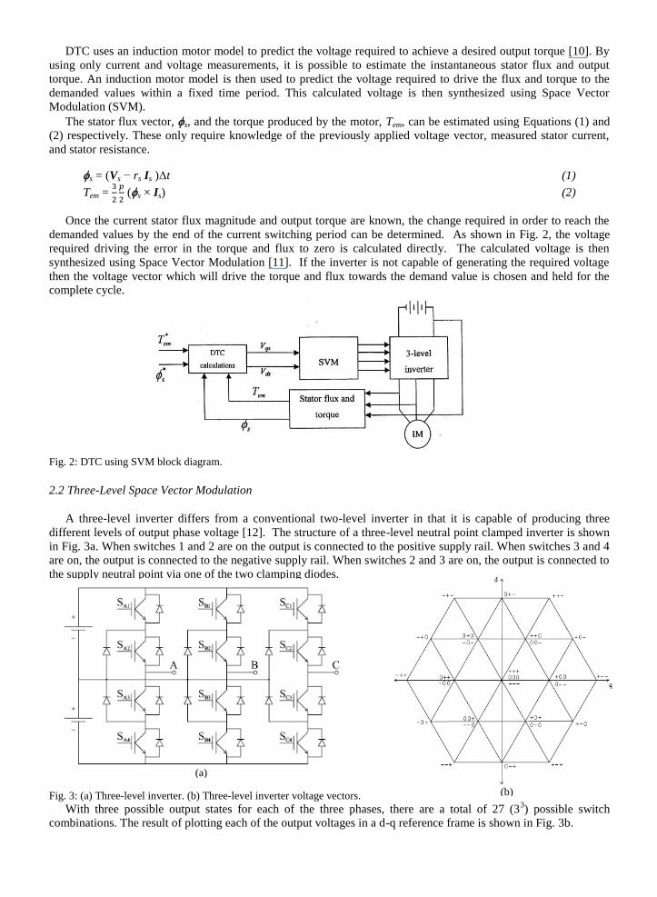
DTC uses an induction motor model to predict the voltage required to achieve a desired output torque [10]. By
using only current and voltage measurements, it is possible to estimate the instantaneous stator flux and output
torque. An induction motor model is then used to predict the voltage required to drive the flux and torque to the
demanded values within a fixed time period. This calculated voltage is then synthesized using Space Vector
Modulation (SVM).
The stator flux vector, s, and the torque produced by the motor, Tem, can be estimated using Equations (1) and
(2) respectively. These only require knowledge of the previously applied voltage vector, measured stator current,
and stator resistance.
s = (Vs − rs Is )Δt (1)
Tem =
(s × Is) (2)
Once the current stator flux magnitude and output torque are known, the change required in order to reach the
demanded values by the end of the current switching period can be determined. As shown in Fig. 2, the voltage
required driving the error in the torque and flux to zero is calculated directly. The calculated voltage is then
synthesized using Space Vector Modulation [11]. If the inverter is not capable of generating the required voltage
then the voltage vector which will drive the torque and flux towards the demand value is chosen and held for the
complete cycle.
Fig. 2: DTC using SVM block diagram.
2.2 Three-Level Space Vector Modulation
A three-level inverter differs from a conventional two-level inverter in that it is capable of producing three
different levels of output phase voltage [12]. The structure of a three-level neutral point clamped inverter is shown
in Fig. 3a. When switches 1 and 2 are on the output is connected to the positive supply rail. When switches 3 and 4
are on, the output is connected to the negative supply rail. When switches 2 and 3 are on, the output is connected to
the supply neutral point via one of the two clamping diodes.
Fig. 3: (a) Three-level inverter. (b) Three-level inverter voltage vectors.
With three possible output states for each of the three phases, there are a total of 27 (33) possible switch
combinations. The result of plotting each of the output voltages in a d-q reference frame is shown in Fig. 3b.
(a)
(b)

Fig. 4 shows that the 27 switch combinations result in a total of 19 unique voltage vectors since some of the
combinations produce the same voltage vector. These different combinations relate to different ways of connecting
the load to the DC bus that result in the same voltage being applied to the motor.
Space Vector Modulation (SVM) is the approximation of an arbitrary vector in the d-q vector space using the
nearest three voltage vectors that the inverter can generate [13]. The nearest three vectors are chosen by
determining the triangle within the vector space in which the desired voltage vector resides. The required on-
duration of each of the vectors is determined by Equations (3) and (4). These specify that the demand vector, V*, is
the geometric sum of the chosen three vectors (V1, V2, V3) multiplied by their on-durations (d1, d2, d3) and that their
on- durations must fill the complete cycle.
(3)
d1 + d2 + d3 = 1 (4)
Equations (3) and (4) can be combined to produce Equation (5). Equation (5) can then be rearranged to obtain
Equation (6). This is an expression for the vector duty cycles in terms of the desired voltage vector and the three
nearest voltage vectors.
(5)
(6)
3. Simulink Model for a DTC Controller
A Simulink model for a DTC controller exploiting SVM is developed. The model is based on the general block
diagram shown in Fig. 2. The model is also evaluated and a modular Simulink induction motor is also presented.
The model consists of four blocks, which design details are given in [14]; in addition to the induction motor block;
each of which corresponds to a block in Fig. 2. These blocks are:
DTC block.
SVM block.
3-level inverter block.
Stator flux and torque estimation block.
The DTC block is shown in Fig. 4.
Fig. 4 Details of the DTC block.
The DTC block design is based on the following analysis:
From the equivalent circuit of an induction motor in d-q reference frame, expression of change in torque and
change in stator flux can be represented as follows:
2
Vd
1
Vq
-1
4/3
0
1
a
b
c
d
Re(A.B)
Im(A.B)
Re(A/B)
Im(A/B)
Re(K.A)
Im(K.A)
Re(1/A)
Im(1/A)
Re(A+B)
Im(A+B)
Re(-A)
Im(-A)
Complex Computer3
a
b
c
d
Re(A.B)
Im(A.B)
Re(A/B)
Im(A/B)
Re(K.A)
Im(K.A)
Re(1/A)
Im(1/A)
Re(A+B)
Im(A+B)
Re(-A)
Im(-A)
Complex Computer2
a
b
c
d
Re(A.B)
Im(A.B)
Re(A/B)
Im(A/B)
Re(K.A)
Im(K.A)
Re(1/A)
Im(1/A)
Re(A+B)
Im(A+B)
Re(-A)
Im(-A)
Complex Computer1
11
E
10
p
9
Ls
8
Ldr
7
Lqr
6
Tdr
5
Tqr
4
Ld
3
Lq
2
Td
1
Tq

(7)
or (8)
Now,
) (9)
Rearranging Equation (9) to extract , we have:
(10)
To evaluate Equation (10), a “complex computer” is needed. Fig. 5 shows the details of the complex computer
block. The complex computer block is built around a block that multiplies two complex numbers: A = a + jb & B =
c + jd .
Fig. 5 Details of the complex computer block.
4. Testing the Simulation
The first step in testing the simulation is to test the operation of the induction motor block. This block is highly
modular model, which enables testing the model at various stages and gaining deep understanding of the machine
operation.
To test the induction machine block model, the following parameters are assumed:
Rr=0.39, Rs=0.19, Lls=0.21×10⁻³
, Llr=0.6×10⁻³
, Lm=4×10⁻³
, fb=100, p=4 and J=0.0226.
A three-phase 50Hz, 220 V ac voltages is applied to the 4-KW induction machine with just the inertia load
(direct ac startup). Figs. 6, 7 and 8 show the three-phase currents, the torque, and the speed of the machine,
respectively. As it can be seen from the figures, the machine accelerates and then gets to steady state in about 0.14
seconds. This shows that the model of the induction machine is working properly. The small slip observed in the
figures is due to the inertia load.
12
Im(-A)
11
Re(-A)
10
Im(A+B)
9
Re(A+B)
8
Im(1/A)
7
Re(1/A)
6
Im(K.A)
5
Re(K.A)
4
Im(A/B)
3
Re(A/B)
2
Im(A.B)
1
Re(A.B)
-1
-1
-1
-1
0
a
b
c
d
re
im
a
b
c
d
re
im
a
b
c
d
re
im
4
d
3
c
2
b
1
a

Fig. 6: Three-phase currents of the induction motor in direct ac startup at steady state.
Fig. 7: Torque in direct ac startup at steady state.
Fig. 8: Angular speed in direct ac startup.
(a) (b)
Fig. 9: (a) Torque and (b) Stator current waveform in steady-state test.

The second step in testing the simulation is to test the SVM-DTC controlled induction motor as a whole system.
In DTC scheme, the cycle period has been assumed equal to 40 μs. The amplitude of the hysteresis bands has been
adjusted in order to achieve a mean inverter switching frequency practically reasonable. The characteristics of the
motor under test is a standard 3-phase, 4-kW, 4-pole, 220 V, 50 Hz induction motor with reference current of 16.6
A, reference torque of (26.5 Nm), and reference speed of 1440 rpm.
The steady-state performance of the DTC scheme is depicted below. Fig. 9a and b shows the torque and the
stator current waveform, respectively.
The transient performance of the DTC scheme has been analyzed and the response to a step variation of the
torque command from 0 Nm to 26.5 Nm (reference torque), at different rotor speeds. Fig. 10a – c illustrates the
torque responses obtained using DTC scheme, at 1200, 600, and 100 rpm, respectively.
Fig. 10: The torque responses obtained using DTC scheme, at (a) 1200, (b) 600, and (c) 100 rpm.
The results above show that the SVM-DTC strategy can be used to achieve better torque response in terms of
settling time and maximum overshoot.
In DTC scheme a direct control of the stator currents is not present and this may determine over currents when
step variations of torque and flux are applied to the input commands.
Fig. 11: Step response of the (a) stator and rotor fluxes, and (b) stator current magnitude.

With reference to the torque, an indirect current control can be obtained introducing a limit to the maximum
torque value. With reference to the stator flux, it can be noted that even a small variation of the stator flux
command causes a large variation of the stator current. This behavior is clearly represented in Fig. 11a and b, which
shows the transients caused by a step variation of the stator flux command. In this case, an indirect control of the
stator current can be easily obtained forcing the flux command to change slowly, according to a prefixed ramp
waveform.
5. Conclusions
According to the results obtained, the following conclusions may be drawn:
1. DTC is preferred over other controlling schemes for high dynamic applications, but, on the other hand, shows
higher current and torque ripple. This drawback can be partially compensated by using SVM in the DTC scheme.
2. The DTC-SVM controlling scheme has the advantage of being easy to implement, making it possible to use
cheap DSP boards to implement sophisticated controllers. However, the technique is also lending itself to more
modern and cheaper implementations using field programmable gate array (FPGA).
3. Controlling schemes based on DTC can achieve better torque responses than other schemes in terms of settling
time and maximum overshoot.
4. Simulink is a very suitable environment for studying and simulating induction machines applications. The
researcher can build quite sophisticated systems from the very basic concepts. This make Simulink models very
suitable for studying complex engineering problems.
5. The Krause’s model of the induction motor is the available mathematical representation of the induction motor
for the purpose of developing Simulink modular model.
6. The modular model developed in this work to simulate the induction motor, gives the user of the model access to
all internal variables which makes for flexibility and deep insight in the machine operation. This model can be
used to simulate any machine control algorithm without using estimators. It can be used to simulate induction
motors, as well as generators without modification. This advantage of the presented model makes it available for
solving any induction machine simulation problem.
References
1. R. Toufouti, S Meziane.and H Benalla, Direct Torque Control for Induction Motor Using Fuzzy Logic, ACSE
Journal, Vol. 6, Issue 2, June, ) 2006(, 17.
2. Xu. Huangsheng, H. A. Toliyat and L.J. Petersen, Five-Phase Induction Motor Drives with DSP-Based Control
System, IEEE Transactions on Power Electronics Vol. 17, Issue 4, Jul. )2002(, 524.
3. Nuno M. Silva, Martins, P. António and Adriano S. Carvalho, Torque and Speed Modes Simulation of a DTC-
Controlled Induction Motor, Proceedings of the 10th Mediterranean Conference on Control and Automation,
Lisbon, Portugal, July 9-12, )2002(.
4. J. Faiz, M. B. B. Sharifian, A. Keyhani and A. B. Proca, Sensorless Direct Torque Control of Induction Motors
Used in Electric Vehicle, IEEE Transactions on Energy Conversion, Vol. 18, No. 1, March )2003(.
5. Shyu, Shang, Chen and Jwo, Flux Compensated Direct Torque Control of Induction Motor Drives for Low
Speed Operation, IEEE Transactions on Power Electronics, Vol. 19, Issue 6, Nov. )2004(, 1608.
6. J. H. Ryu, K. W. Lee and J. S. Lee, A Unified Flux and Torque Control Method for DTC-Based Induction-
Motor Drives, IEEE Transactions on Power Electronics, Vol. 21, Issue. 1, )2006(, 234.
7. E. Ohno, Introduction to Power Electronics, Ohm-sha, Tokyo, 1984.
8. P. Vas, “Sensorless Vector and Direct Torque Control,” Oxford University Press, )1998(.
9. D. Casadei, G. Serra and A. Tani, Improvement of Direct Torque Control Performance by Using a Discrete
Space Vector Modulation Technique, IEEE Transactions on Power Electronics, Vol. 13, No. 2, 997, (1998).
10. G. Habelter, F. Profumo, M. Pastorelli and L. Tolbert, Direct Torque Control of Induction Machines Using
Space Vector Modulation, IEEE Trans. on Industry Applications, Vol. 28, No. 5, Sep./Oct. (1992), 1045.
11. C. Lascu, I. Boldea and F. Blaajerg, A Modified Direct Torque Control For Induction Motor Sensorless Drive,
IEEE Trans. on Industry Applications, Vol. 36, No. 1, Jan./Feb. (2000), 122.
12. P. Vas, "Electrical Machines and Drives: A Space-Vector Theory Approach" Oxford University Press, (1992).
13. J. Kang, and S. Sul, New Direct Torque Control of Induction Motor for Minimum Torque Ripple and Constant
Switching Frequency, IEEE Trans. on Industry App., Vol. 35, No. 5, Sep./Oct. (1999), 1076.
14. Ahmad I. N. Al-Shawi, ,"Space Vector Modulation Direct Torque Speed Control of Induction Motor", Thesis,
Nahrain University, Dec., (2007).