Variable-Speed Centrifugal Chiller Control ... - Purdue e-Pubs
Upload
khangminh22Category
view
0download
0
Altivar 71 and Altivar 71 Plusvariable speed drivesfor 3-phase motors from .5 to 2100 HP, .37 to 1550 kW
e-Catalog
2014

This page was intentionally left blank.

3
Altivar 71variable speed drives
Contents
Introduction.........................................................4 v Applications.............................................................5 v Product Range...…………………………….......……..6 v Options………………………………………………..9
Specifications.........................................................10 v Electrical..................................................................10 v Environmental..........................................................12 v Certifications & Compliance....................................13 v I/O & Control............................................................14 v Integrated Communication Port...............................15
Application Information….........………..…………..……16 Selection Tables..............................................................19
v Dimensions..............................................................19 v Short Circuit Current Ratings....................................23
Accessories & Options...................................................29 v Product Variant Options...........................................29 v Mounting Options....................................................30 v Configuration Tools..................................................33 v Options Common to Altivar 71..................................35 v Graphic Display Keypad.........................................36 v Encoder Interface Card Options.............................38 v I/O Extension Card Options.....................................39 v IMC Controller Card................................................42 v Communication Card Options..................................47 v Dynamic Braking Accessories.................................53
Input Power Options………..........………………………..58 v Line Reactors…...........………………….......……….58 v Passive Filters….......……………………....…………61 v EMC Filters……….......………………….......………..63
Output Power Options…….............………………………65 v dV/dt Output Filters….......…………….…...………..65
M-Flex......................................................................66 v Introduction…………......……………………….66 v Specifications……...….……………………….68 v Selection Table…................…………………....…....69 v Options.......................................................70 v Dimensions……………..……………………….71
Altivar Plus 125-700 HP...................................................72 v Introduction……......……………………………..72 v Specifications..............................................74 v Selection Table.........................................................75 v Dimensions...................................................76
Altivar Plus 700-2100 HP.................................................79 v Introduction........................................................79 v Specifications...................................................80 v Selection Table.........................................................82 v Dimensions........................................................83
Quality Assurance...........................................................86Services & Support.........................................................88

4
Altivar 71variable speed drives
IntroductionThe Altivar™ 71 variable-speed drive is built for industrial and process equipment. It
has been designed to excel in applications that demand high motor performance.
The range offers a complete AC drive product family with advanced functionality that
incorporates a simple user interface, common I/O options, and flexible
communication options with leading motor performance in open loop or closed loop,
over the widest horsepower range in the industry.
The Altivar 71 variable-speed drive enables you to:
Reduce installation costs by matching drive HP to motor HP to obtain high motor performance without the need to oversize the drive.
Manage data in real time by offering connection to all major networks.
Easily configure, update, and check status via the large, customizable display and navigation wheel.
Protect your drive, motor, connected equipment, and the environment.
Features and benefits of the Altivar 71:
Reduce start-up time with seven built-in macros for applications such as material handling, hoisting, master-slave control, and network configuration.
Efficiently manage your installed base across a wide horsepower range with the common user interface, I/O, and network options.
Improve machine performance and process throughput with dual microprocessors dedicated to motor and I/O control.
Save panel space with side-by-side mounting and maximize product life with superior resistance to high temperatures.
Easily integrate into your machines with flexible I/O and communication options.
Prevent unintended motor operation with STO (Safe Torque Off) power removal input.
An extensive range with a wide selection of options
Introduction

5
Altivar 71variable speed drives
Introduction
Hoisting application
Wood-working machine application
Packaging application
Applications The Altivar 71 excels at the following types of applications:
b 150% overload for 60 seconds, or momentary loads of up to 220%, such as aggregate conveyance, package gapping, sorters, crushers, and cutting equipment
b High starting torque and maximum motor torque at low speeds such as hoisting, extruders, and metal forming machinery
b High dynamic speed response to changing loads such as palletizers, packaging, winding, mixing, and process machine applications
b Motor encoder feedback to provide motor rotation required in some hoisting and positioning equipment
b Flexibility for unbalanced machines with the ENA (ENergy Adaptation) System
The Altivar 71 drive's advanced functions boost performance levels and make machines more versatile so they can be used for a large number of applications.
Hoisting b Brake control adapted for translational, hoisting and slewing movements b Load measurement using weight sensor b High-speed hoisting b Brake feedback management b Limit switch management
Material handling b Quick response times on transmission of a command: 2 ms (± 0.5 ms) b Speed reference via pulse train or differential analog input b Control via the principal communication networks b Position control via limit switches with time optimization at low speed b Multiple parameter settings via parameter set switching
Packaging b Up to 50 Hz of bandwidth b Quick response times on change of reference 2 ms (± 0.5 ms) b Control via integrated CANopen machine bus b Position control via limit switches
Material-working machines b High-speed operation b Fast controlled stop on loss of line supply b Control via integrated machine controller (IMC) card b Protection of material against over torque
Process machinery b PID regulator b High-resolution references b Speed control or torque control b Connection to common communication networks b Separate control section power supply b Managed braking torque b Common DC bus connection
Applications

6
Altivar 71variable speed drives
Introduction
1.................30.............................100
HP
Enclosure
Field platform
Basic Altivar 71 platform +
conduit kit
Basic Altivar 71 platform
200...240 V single phase
Type 3R
Type 1
IP 20
1.....................40.........................100HP
Enclosure
Field platform
200...240 V three phase
Basic Altivar 71 platform
Basic Altivar 71 platform + conduit kit
M-Flex & MCC
M-Flex & MCC platform
IP 20
Type 1
Type 3R
Type 12
M-Flex & MCC platform
1.....75....125.....450.......700..............1800
HP
Enclosure
Field platform
380...480 V three phase
Basic Altivar 71 platform
Basic Altivar 71 platform + conduit kit
M-Flex & MCC
Altivar Plus platform
IP 20
Type 1
Type 3R
Type 12
..2...125......350...450.......700.....1800HP
Enclosure575...690 V three phase
Basic Altivar 71 platform
Basic Altivar 71 platform + conduit kit
MCC platform
Altivar Plus platform
IP 20
Type 1
Type 12
Basic Altivar 71 platform
Altivar Plus
M-Flex & MCC platform
Field platform
Product rangeThe Altivar 71 range of variable speed drives covers a wide range of motor power ratings from .5 to 2100 HP, .37 to 1550 kW in three voltage ranges.
In addition to the enclosure options listed below, customized enclosed options can be provided by Schneider Electric Drives Systems.
Product Range

7
Altivar 71variable speed drives
Introduction
Eco-friendly and energy-savingThe Altivar 71 drive has been designed to provide significant energy savings in industrial processes, that have un-balanced loads. It has been designed as an eco-friendly product (using 90 % recyclable materials, compliant with environmental standard ISO 14040). It is RoHS-compliant.
Compliance with international standards and certificationsThe entire range conforms to international standards IEC/EN 61800-5-1, IEC/EN 61800-2, IEC/EN 61800-3, is UL 508C, CSA, DNV, C-Tick, NOM 117 and GOST certified, and has been developed to meet the requirements of directives regarding the protection of the environment (RoHS, WEEE, etc.) as well as those of European Directives (e mark).
Functional safety and ATEX applications The Altivar 71 drive features a Power Removal safety function that is designed to help ensure motor stopping and help prevent accidental restarts. This safety function means that the drive can be installed as part of the safety system for an Electrical/Electronic/Programmable Electronic control system relating to the safety of a machine or industrial process.
It meets the requirements of category 3 of the ISO 1384 machine safety standard, SIL 2 of IEC/EN 61508 and standard IEC/EN 61800-5-2 which covers the functional safety requirements of power drive products. The Power Removal safety function also enables the Altivar 71 drive to offer protection for motors installed in explosive atmospheres (ATEX certification).
Product range (continued)The Altivar 71 AC drive is designed for the control of three-phase asynchronous and synchronous motors in constant-torque applications. It includes an LCD Graphic display keypad with an easy-to-read display and navigation wheel that allows users to scroll through drop-down menus.
The Altivar 71 comes standard with: LCD graphic keypad, eight lines of 24 characters Integrated RJ45 port, Modbus, or CAN networks selectable Removable control terminal block with the following I/O:
Six logic inputs One power removal input Two analog inputs One analog output Two relay outputs (1NO/NC, 1NO)
The Altivar 71 drive integrates the Modbus and CANopen protocols as standard, as well as over 150 functions. These functions can be extended using communication option cards, I/O extension cards, and encoder interface or an Integrated Machine controller card, which allows customer programming in the SoMachine environment.
External options such as braking resistors, line and load reactors, and filters complete the offer.
Mounting options The Altivar 71 drive can be mounted in a variety of ways for integration in various devices.
Wall Mounting The Altivar 71 can be mounted directly on a wall without having to be installed inside an enclosure. UL Type 1 can be achieved using kit VW3A92pp.
Flange-mounting in enclosureThe Altivar 71 drive has been designed to optimize the size of enclosures. This type of flange-mounting can be used to reduce the size of enclosure required and to limit the temperature rise inside the enclosure:
b The power section, with Type 12/IP 54 degree of protection, can be mounted outside the enclosure using kit VW3A95pp.This type of mounting can lead to ambient temperatures of up to 60°C inside the enclosure without derating. It may be necessary to use a control card fan kit VW3A94pp appropriate for the drive rating in order to avoid hot spots.
Electromagnetic compatibilityObserving requirements of electromagnetic compatibility were considered right from the design stage. The incorporation of EMC filters in ATV71HpppM3, ATV71ppppN4, and ATV71ppppY drives and the recognition of EMC requirements facilitates installation and provides economical means of helping ensuring that machines receive the e mark. ATV71HpppM3X and ATV71HpppS6X drives have been designed without an EMC filter. Filters are available as an option and can be installed by the customer to reduce the level of emissions.
Product Range

8
Altivar 71variable speed drives
Graphic display keypad & configuration toolsGraphic display keypad
The Altivar 71 drive (1) is supplied with a graphic display keypad (2). It is user-friendly, offering quick and easy access to the plain text menus and advanced functions, and online help screens in six languages. Four configuration files can be stored in the graphic display keypad.
Customizable units can be created to display machine applicable data. It can be mounted remotely on an enclosure door with Type 12 or IP 54 degree of protection. The drive’s application functions are easily accessible via the user dial and programmable function keys on the display unit.
SoMove setup software (3)SoMove software for PCs can be used to configure, adjust and debug the Altivar 71 drive with the Oscilloscope function and also for maintenance of this drive. It can also be used to customize the integrated display keypad menus. It can be used with a direct cable connection or a Bluetooth® wireless connection. The Altivar 71 requires the use of the Modbus-Bluetooth® adaptor (4).
Simple Loader and Multi-Loader programming toolsThe Simple Loader tool (5) enables one drive's configuration to be downloaded, saved, and up-loaded with a simple, two button device.
The Multi-Loader tool (6) enables a number of configurations to be stored from the SoMove software to be saved or copied and downloaded to another drive. The Altivar 71 drives must be powered up.
Quick programmingSimply Start menu
The Simply start menu can be used to quickly enter the minimum parameters to get the drive running, maximize motor performance and provide motor protection.
The architecture, the hierarchical parameter structure and the direct access functions serve to make programming quick and easy, even for the more complex functions.
Macro-configurationThe Altivar 71 drive offers quick and easy programming using macro-configurations for different applications:
b Simple start-stop applications b Material handling b Hoisting b General use b Connection to communication networks b PID regulator applications b Master/slave applications
After a macro configuration is selected, the user can further modify and customize the settings.
Introduction
5
Product Range
or
2
3
4
1
Built-in, monitoring and diagnostic functions The Altivar 71 has numerous built-in monitoring and diagnostic functions:
b Built-in drive test functions with diagnostic screen on the graphic display keypad b I/O maps for active status display of inputs and outputs b Communication maps for the different ports b Oscilloscope function that can be viewed using the SoMove setup software b Apply filtering and scaling to analog inputs and outputs b Remote use of these functions by connecting the drive to an identification of the
drive's part number, ratings and software versions b Error logs with display of the value of up to 16 variables at time of a fault b Add timing delays to logic inputs, logic outputs and relay outputs b A service message of up to 5 lines of 24 characters can be stored in the drive
6

9
Altivar 71variable speed drives
Introduction
1 3
22
ATV 312
M340 PLC
OTB I/O Sensor
CANopen master
Ethernet
STB I/O
ATV 71Magelis XBT
Modbus
A wide range of options The Altivar 71 has a wide range of options to adapt to a variety of installations and applications.
Option cardsThe Altivar 71 drive (1) can integrate up to three different option cards simultaneously, including:
b Two of the following cards: v I/O extension cards (two versions available) (2) v Communication cards (2) v Integrated Machine Controller programmable card (2) to adapt the variable
speed drive to specific applications b One encoder interface cards (3): RJ45
Other optionsNumerous other external options can be combined with the Altivar 71:
b Flange Mounting kits to mount the heatsink outside of an enclosure b Dynamic braking resistors b Type 1 Conduit kits which provide conduit landing when wall mounting the drive b Active Front End (AFE) to use the drive to return energy to the line supply or when
the installation requires particularly low harmonic levels. The AFE is available via our Drive Systems group
b Line reactors and passive filters to reduce harmonic currents b Additional EMC input filters to reduce conducted emissions on the incoming power
line b Load reactors and output filters for long cable runs
Integration into PLC architectures The Altivar 71 drive has a built-in combined Modbus or CANopen port for quick, accurate control, adjustment, supervision and configuration. A second RJ45 port is available on the face of the product and can accept the graphic display keypad or for a Magelis terminal for a user interface.
The Altivar 71 drive can be integrated into many networked industrial applications using the communication option cards. The following protocols are available: Modbus TCP Daisy Chain, Modbus/Uni-Telway, EtherNet/IP, DeviceNet, PROFIBUS DP V0 and V1, and Profinet.
The option of powering the control section separately enables communication (monitoring, diagnostics) to be maintained even if there is no power supply to the control section.
The Integrated Machine Controller (IMC) card transforms the drive into an automation island. This is used to adapt the drive to customized applications by decentralizing the control system functions:
b The IMC card has additional I/O; it can also manage the drive I/O and an I/O extension card.
b It contains onboard application programs developed in IEC/EN 61131-3 languages.
b Its CANopen master port enables control of other drives and dialogue with I/O modules and sensors.
Options

10
Altivar 71variable speed drives Electrical
Specifications
Electrical SpecificationsInput power Voltage V 200 - 15%...240 + 10% single phase for ATV 71H075M3...HD45M3X
200 - 15%...240 + 10% three-phase for ATV 71HpppM3 and ATV 71HpppM3X380 - 15%...480 + 10% three-phase for ATV 71ppppN4500 - 15%…690 + 10% three-phase for ATV 71HpppY500 - 15%...600 + 10% three-phase for ATV71HpppS6X
Frequency Hz 50 - 5%...60 + 5%
Drive output voltages V Maximum three-phase voltage equal to line supply voltage
Output frequency range ATV 71HpppM3ATV 71HD11M3X…HD37M3XATV 71H075N4…HD37N4ATV71HpppS6X
Hz 0...599 on standard product. 0...1600 operation is available in product with specific firmware. Delivery of product requires compliance with Control of Export EU Regulation No 961/2010, Section II.A3. 003
ATV 71HD45M3X…HD75M3XATV 71HD45N4…HC50N4ATV 71HpppY
Hz 0...500
Configurable switching frequency
ATV 71HpppM3ATV 71HD11M3X, HD15M3XATV 71H075N4…HD30N4ATV71HpppS6X
kHz Nominal switching frequency: 4 kHz without derating in continuous operation.Adjustable during operation from 1…16 kHzAbove 4 kHz, see the derating curves in the Installation Manual.
ATV 71HD18M3X, HD45M3XATV 71HD37N4…HD75N4
kHz Nominal switching frequency: 2.5 kHz without derating in continuous operation.Adjustable during operation from 1…16 kHzAbove 2.5 kHz, see the derating curves in the Installation Manual.
ATV 71HD55M3X, HD75M3XATV 71HD90N4…HC50N4
kHz Nominal switching frequency: 2.5 kHz without derating in continuous operation.Adjustable during operation from 2.5…8 kHzAbove 2.5 kHz, see the derating curves in the Installation Manual.
ATV 71HU22Y…HD30Y kHz Nominal switching frequency: 4 kHz without derating in continuous operation.Adjustable during operation from 2.5…6 kHzAbove 4 kHz, see the derating curves in the Installation Manual.
ATV 71HD37Y…HC63Y kHz Nominal switching frequency: 2.5 kHz without derating in continuous operation.Adjustable during operation from 2.5…4.9 kHzAbove 2.5 kHz, see the derating curves in the Installation Manual.
Speed range ATV 71HpppM3ATV 71HpppM3XATV 71ppppN4ATV 71HpppS6X
Asynchronous motor: � 1…1000 in closed-loop mode with encoder feedback � 1…100 in open-loop mode without encoder feedback
Synchronous motor: � 1…50 in open-loop mode without encoder feedback
ATV 71HpppM3383ATV 71HpppM3X383ATV 71HpppN4383
Synchronous motor: � 1…1000 in closed-loop mode with encoder feedback
Speed accuracy For a torque variation of 0.2 Tn to Tn
± 0.01% of nominal speed, in closed-loop mode with encoder feedback± 10% of nominal slip, without encoder feedback
Torque accuracy ± 5% in closed-loop mode with encoder feedback± 15% in open-loop mode without encoder feedback
Transient overtorque 170% of the nominal motor torque (typical value at ± 10%) for 60 s every 10 minutes220% of the nominal motor torque (typical value at ± 10%) for 2 s
Braking torque 30% of nominal motor torque without braking resistor (typical value)Up to 150% with braking resistor installed as an option
Maximum transient current 150% of the nominal drive current for 60 s (typical value)220% of the nominal drive current for 2 s (typical value)
Permanent torque at 0 Hz
ATV 71H037M3…HD45M3XATV 71H075N4…HD75N4ATV71HpppS6XATV 71HU22Y…HD90Y
The Altivar 71 drive can continuously supply the peak value of the nominal drivecurrent
ATV 71HD55M3X, HD75M3XATV 71HD90N4…HC50N4ATV 71HC11Y…HC63Y
The Altivar 71 drive can continuously supply 80% of the peak value of the nominaldrive current
Motor control profiles ATV 71HpppM3ATV 71HpppM3XATV 71ppppN4ATV 71HpppS6XATV 71HpppY
Asynchronous motor: � Flux Vector Control (FVC) with sensor (current vector) � Sensorless Flux Vector Control (SFVC) (voltage or current vector) � Voltage/frequency ratio (2 or 5 points) � ENA (Energy Adaptation) System for unbalanced loads
Synchronous motor: � Vector control without speed feedback
ATV 71HpppM3383ATV 71HpppM3X383ATV 71HpppN4383
Synchronous motor: � Vector control with speed feedback

11
Altivar 71variable speed drives Electrical
Specifications
Electrical Specifications (continued)Frequency loop PI regulator with parameters to adjust response time.
Slip compensation Automatic. Can be suppressed or adjusted.
Drive noise level Conforming to directive 86-188/EEC
ATV 71H037M3…HU15M3, ATV 71H075N4…HU22N4 dBA 43
ATV 71HU22M3…HU40M3, ATV 71HU30N4, HU40N4 dBA 54.5
ATV 71HU55M3, ATV 71HU55N4, HU75N4 dBA 55.6
ATV 71HU75M3, ATV 71HD11N4, ATV71HpppS6X dBA 57.4
ATV 71HD11M3X, HD15M3X, ATV 71HD15N4, HD18N4 dBA 60.2
ATV 71HD18M3X, HD22M3X, ATV 71HD22N4, ATV 71HU22Y…HD30Y
dBA 59.9
ATV 71HD30M3X…HD45M3X, ATV 71HD30N4, HD37N4 dBA 64
ATV 71HD45N4…HD75N4, ATV 71HD37Y…HD90Y dBA 63.7
ATV 71HD55M3X, ATV 71HD90N4 dBA 60.5
ATV 71HD75M3X, ATV 71HC11N4 dBA 69.5
ATV 71HC13N4, HC16N4 dBA 66
ATV 71HC20N4…HC50N4, ATV 71HC11Y…HC63Y dBA 77
Indicator LED 1 red LED: LED lit indicates the presence of drive voltage
Electrical impedance Inductance of approximately 1-2%
ATV71H037M3...HU75M3, ATV71H075N4...HD15N4, ATV71HU15S6X...HU75S6X, ATV71HU22Y...HD11Y
ATV71HD11M3X...HD45M3X, ATV71HD18N4...HD75N4ATV71HD15Y...HD90Y
Integrated DC choke Inductance of approximately 2-3%
ATV71HD55M3X...HD75M3X, ATV71HD90N4...HC50N4 ATV71HC11Y...HC50Y
DC choke ships with drive for field installationInductance of approximately 3%
ATV71HD55M3XD...HD75M3XD, ATV71HD90N4D...HC50N4D
DC choke is not included with driveRequires inductance of approximately 3%, such as AC line reactor be installed.
Electrical isolation Between power and control (inputs, outputs, power supplies)
Acceleration and deceleration ramps Ramp profiles: � Linear, can be adjusted separately from 0.01 to 9999 s � S, U or customized
Automatic adaptation of deceleration ramp time if braking capacities exceeded, possible inhibition of this adaptation (use of braking resistor)
Braking to a standstill By DC injection: � By a command on a programmable logic input � Automatically as soon as the estimated output frequency drops to < 0.1 Hz, period
adjustable from 0 to 60 s or continuous, current adjustable from 0 to 1.2 In (in open loopmode only).
Main drive protection and protection features Thermal protection: � Against overheating � Of the power stage
Protection against: � Short-circuits between motor phases � Input phase breaks � Overcurrents between output phases and ground � Overvoltages on the DC bus � A break on the control circuit � Exceeding the limit speed � Line supply overvoltage and undervoltage � Input phase loss, in three-phase
Motor protection Thermal protection integrated in drive via continuous calculation of I2t taking speedinto account:
� The motor thermal state is saved when the drive is powered down. � Function can be modified via operator dialogue terminals, depending on the type of
motor (force-cooled or self-cooled).Protection against motor phase breaksProtection with PTC probes
Dielectric strength ATV 71HpppM3ATV 71HpppM3X
Between ground and power terminals: 2830 V cBetween control and power terminals: 4230 V c
ATV 71ppppN4ATV 71HpppS6X
Between ground and power terminals: 3535 V cBetween control and power terminals: 5092 V c
ATV 71HpppY Between ground and power terminals: 3110 V cBetween control and power terminals: 5345 V c
Insulation resistance to ground > 1 M��(electrical isolation) 500 V c for 1 minute
Frequency resolution Display units Hz 0.1
Analog inputs Hz 0.024/50 Hz (11 bits)

12
Altivar 71variable speed drives Environmental
Specifications
Environmental SpecificationsVibration resistance ATV 71HpppM3
ATV 71HD11M3X…HD45M3XATV 71H075N4…HD75N4ATV 71HU22Y…HD90YATV71HpppS6X
1.5 mm peak to peak from 3…13 Hz, 1 gn from 13…200 Hz, conforming to IEC/EN 60068-2-6
ATV 71HD55M3X, HD75M3XATV 71HD90N4…HC50N4ATV 71HC11Y…HC63Y
1.5 mm peak to peak from 3…10 Hz, 0.6 gn from 10…200 Hz, conforming to IEC/EN 60068-2-6
Shock resistance ATV 71HpppM3ATV 71HD11M3X…HD45M3XATV 71H075N4…HD75N4ATV 71HU22Y…HD90YATV71HpppYATV71HpppS6X
15 gn for 11 ms conforming to IEC/EN 60068-2-27
ATV 71HD55M3X, HD75M3X ATV 71HD90N4…HC13N4 ATV 71HC11Y…HC16Y
7 gn for 11 ms conforming to IEC/EN 60068-2-27
ATV 71HC16N4…HC50N4ATV 71HC20Y…HC63Y
4 gn for 11 ms conforming to IEC/EN 60068-2-27
Maximum ambient pollutionDefinition of insulation
ATV 71HpppM3ATV 71HD11M3X, HD15M3XATV 71H075N4…HD18N4ATVHpppS6X
Degree 2 conforming to IEC/EN 61800-5-1
ATV 71HD18M3X…HD75M3XATV 71HD22N4…HC50N4ATV 71HpppY
Degree 2 conforming to IEC/EN 61800-5-1Degree 3 in accordance with UL marking conforming to UL840
Environmental conditions Use
ATV 71HpppM3,ATV 71HD11M3X...HD45M3X ATV 71H075N4…HD75N4ATV71HpppS6X
IEC 60721-3-3 classes 3C1 and 3S2
ATV 71HpppM3S337ATV 71HD11M3X337...HD45M3X337ATV 71HD55M3X, HD75M3XATV 71H075N4S337…HD75N4S337ATV 71HD90N4…HC50N4
IEC 60721-3-3 class 3C2
Relative humidity % 5…95% without condensation or dripping water conforming to IEC 60068-2-3
Ambient airtemperature around thedevice
Operation °C For ATV 71Hppppp drives: - 10…+ 50 without deratingUp to + 60°C with derating and with the control card fan kit VW3 A9 4pp correspondingto the drive rating.See the derating curves in the Installation Manual.
Storage °C - 25…+ 70
Note: UL rating is for up to 40 °C. Higher temperature ratings listed above are for non-UL applications only.
Maximum operating altitude
ATV 71HpppM3ATV 71HpppM3XATV 71HpppN4
m 1000 without derating1000…3000 derating the current by 1% per additional 100 m. Limited to 2000 m forthe “Corner Grounded” distribution network
ATV 71HpppY m 1000 without derating1000…2260 derating the current by 1% per additional 100 m.
Operating positionMaximum permanent angle in relation to the normal vertical mounting position
10° 10°

13
Altivar 71variable speed drives
Specifications
Certifications and ComplianceConformity to standards
Altivar 71 drives have been developed to conform to the strictest international standards and the recommendations relating to electrical industrial control devices (IEC, EN), in particular: low voltage, IEC/EN 61800-5-1, IEC/EN 61800-3 (conducted and radiated EMC immunity and emissions).
Protection IEC/EN 61800-3, Environments 1 and 2 (EMC requirements and specific test methods)IEC/EN 61000-4-2 level 3 (electrostatic discharge immunity test)IEC/EN 61000-4-3 level 3 (radiated, radio-frequency, electromagnetic field immunity test)IEC/EN 61000-4-4 level 4 (electrical fast transient/burst immunity test)IEC/EN 61000-4-5 level 3 (surge immunity test)IEC/EN 61000-4-6 level 3 (immunity to conducted disturbances, induced by radio-frequency fields)IEC/EN 61000-4-11 (voltage dips, short interruptions and voltage variations immunity tests)
Conducted EMC emissions for drives
IEC/EN 61800-3, environments 1 and 2, categories C1, C2, C3
ATV 71H037M3…HU22M3ATV 71H075N4…HU40N4
Integrated EMC filter meets EN 55011 class A group 1, IEC/EN 61800-3 category C2Use with additional EMC filter to meet:
� EN 55011 class B group 1, IEC/EN 61800-3 category C1
ATV 71HU30M3…HU75M3ATV 71HU55N4…HC50N4ATV 71HpppS6X
Integrated EMC filter meets EN 55011 class A group 2, IEC/EN 61800-3 category C3Use with additional EMC filter to meet:
� EN 55011 class A group 1, IEC/EN 61800-3 category C2 � EN 55011 class B group 1, IEC/EN 61800-3 category C1
ATV 71HpppM3X Use with additional EMC filter to meet: � EN 55011 class A group 1, IEC/EN 61800-3 category C2 � EN 55011 class B group 1, IEC/EN 61800-3 category C1
ATV 71HpppY Integrated EMC filter meets EN 55011 class A group 2, IEC/EN 61800-3 category C3
e marking The drives are marked e according to the European low voltage (2006/95/EC) and EMC (89/336/EEC) directives
Product certifications ATV 71HpppM3ATV 71HD11M3X...HD45M3XATV 71HD55M3XD,HD75M3XDATV 71H075N4…HD75N4ATV 71HD90N4D…HC50N4DATV 71HpppS6XATV 71HpppY
UL 508C, CSA, C-Tick, NOM 117 and GOSTABS, DNV
Degree of protection IEC/EN 61800-5-1, IEC/EN 60529
ATV 71HpppM3ATV 71HD11M3X…HD45M3XATV 71H075N4…HD75N4ATV71HpppS6XATV 71HU22Y…HD90Y
IP 21, IP 41 on upper part, IP 54 on isolated power component and heatsink section, UL Type 1 with accessory VW3A92pp
ATV 71HD55M3X, HD75M3XATV 71HD90N4…HC50N4ATV 71HC11Y…HC63Y
IP 00, IP 41 on upper part and IP 30 on front panel and side parts.IP 54 on isolated power component and heatsink section UL Type 1 with accessory VW3A92pp
Certification & Compliance

14
Altivar 71variable speed drives I/O & Control
Specifications
Analog input AI1-/AI1+ 1 bipolar differential analog input ± 10 V c (maximum voltage 24 V). Max. sampling time: 2 ms ± 0.5 ms.Resolution: 11 bits + 1 sign bit. Accuracy: ± 0.6% for a temperature variation of 60°C. Linearity: ± 0.15% of maximum value.
AI2 1 software-configurable voltage or current analog input: � Voltage analog input 0...10 V c, impedance 30 k� (max. voltage 24 V) � Current analog input X-Y mA by programming X and Y from 0 to 20 mA, with impedance 242 �
Max. sampling time: 2 ms ± 0.5 ms. Resolution: 11 bits. Accuracy: ± 0.6% for a temperature variation of 60°C. Linearity: ± 0.15% of maximum value.
Other inputs Available on I/O option cards.
Analog output AO1 1 analog output software-configurable for voltage or current or as a logic output: � Voltage analog output 0...10 V c, min. load impedance 470 � � Current analog output X-Y mA by programming X and Y from 0 to 20 mA, max. load impedance 500 �
Max. sampling time: 2 ms ± 0.5 ms. Resolution: 10 bits. Accuracy: ± 1% for a temperature variation of 60°C. Linearity: ± 0.2%.
� Logic output: 10 V, 20 mA maximum
Other outputs Available on I/O option cards.
Relay outputs R1A, R1B, R1C 1 relay logic output, one “N/C” contact and one “N/O” contact with common point. Minimum switching capacity: 3 mA for 24 V c. Maximum switching capacity:
� On resistive load (cos���= 1): 5 A for 250 V a or 30 V c � On inductive load (cos ���= 0.4 and L/R = 7 ms): 2 A for 250 V a or 30 V c
Max. response time: 7 ms ± 0.5 ms. Electrical service life: 100,000 operations.
R2A, R2B 1 relay logic output, one “N/O” contact. Minimum switching capacity: 3 mA for 24 V c.Maximum switching capacity:
� On resistive load (cos ��� = 1): 5 A for 250 V a or 30 V c � On inductive load (cos ��� = 0.4 and L/R = 7 ms): 2 A for 250 V a or 30 V c
Max. response time: 7 ms ± 0.5 ms. Electrical service life: 100,000 operations.
Other outputs Available on I/O option cards.
LI logic inputs LI1…LI5 5 programmable logic inputs 24 V c, compatible with level 1 PLC, IEC/EN 61131-2 standardImpedance: 3.5 k�. Maximum voltage: 30 V. Max. sampling time: 2 ms ± 0.5 ms. Multiple assignment makes it possible to configure several functions on one input (example: LI1 assigned to forward and preset speed 2, LI3 assigned to reverse and preset speed 3)
LI6 1 logic input, switch-configurable as a logic input or as an input for PTC probes. Logic input, characteristics identical to inputs LI1...LI5Input for a maximum of 6 PTC probes mounted in series:
� Nominal value < 1.5 k� � Trip resistance 3 k�, reset value 1.8 k� � Short-circuit protection < 50 �
This logic input must never be used to protect an ATEX motor in applications in explosive atmospheres
Positive logic (Source) State 0 if y 5 V or logic input not wired, state 1 if u 11 V
Negative logic (Sink) State 0 if u 16 V or logic input not wired, state 1 if y 10 V
Other inputs Available on I/O option cards.
Safety input PWR 1 input for the Power Removal safety function and/or for thermal protection of the ATEX motor in applications in explosive atmospheres. The PWR (Power Removal) safety input, also known as STO (Safe Torque Off) can be used to stop applying power to the motor and/or prevent a motor from restarting unintentionally. The PWR input allows the Altivar 71 to be installed as a part of the safety related system. This function complies with:
� Standard for safety of machinery EN 954-1 category 1 or category 3. � Standard for functional safety IEC/EN 61508 � Drives system standard IEC/EN 61800-5-2, SIL 2 capability. � Standards for functional safety EN ISO 13849-1: category 3PLd � Standard IEC/EN 61508 SIL 1, stopping category 0 or IEC/EN 6UI508 SIL 2, stopping category 1
The PWR (Power Removal) safety input can also be connected to a thermal sensor switch integrated in a motor used in explosive atmospheres to meet ATEX requirements:
� Power supply: 24 V c (max. 30 V) � Impedance: 1.5 k� � State 0 if < 2 V, state 1 if > 17 V � Response time: <100 ms
I/O and Control SpecificationsAvailable internal supplies Short-circuit and overload protection:
� 1 x 10.5 V c ± 5% supply for the reference potentiometer (1 to 10 k�), maximum current 10 mA � 1 x 24 V c supply (min. 21 V, max. 27 V), maximum current 200 mA
For external + 24 V power supply 24 V c (min. 19 V, max. 30 V)Power 30 W

15
Altivar 71variable speed drives
Specifications
Modbus protocolType of connection Modbus RJ45 port on face of product Modbus RJ45 network port
Structure Physical interface 2-wire RS 485
Transmission mode RTU
Transmission speed Configurable via the display keypad or the SoMoveTM PC software: 9600 bps or 19200 bps
Configurable via the display keypad or the SoMove PC software:4800 bps, 9600 bps, 19200 bps or 38.4 kbps
Format Fixed = 8 bits, even parity, 1 stop Configurable via the display keypad or the SoMove PC software:- 8 bits, odd parity, 1 stop- 8 bits, even parity, 1 stop- 8 bits, no parity, 1 stop- 8 bits, no parity, 2 stop
Polarization No polarization impedancesThese should be provided by the wiring system (for example, in the master)
Address 1 to 247, configurable via the terminal or the SoMove PC software.3 addresses can be configured in order to access the drive data, the “Controller Inside”programmable card and the communication card respectively.These 3 addresses are identical for the connector and network ports.
Services Device profiles 2 profiles: CiA 402 (“Device Profile Drives and Motion Control”) and I/O profile
Messaging Read Holding Registers (03) 63 words maximumWrite Single Register (06)Write Multiple Registers (16) 61 words maximumRead/Write Multiple Registers (23) 63/59 words maximumRead Device Identification (43)Diagnostics (08)
Communication monitoring Can be inhibited.“Time out,” which can be set between 0.1 s and 30 s
CANopen protocolStructure Connector This connects to the Modbus RJ45 Modbus network port.
Network management Slave
Transmission speed 20 kbps, 50 kbps, 125 kbps, 250 kbps, 500 kbps or 1 Mbps
Address (Node ID) 1 to 127, configurable via the terminal or the SoMove PC software
Services Number of PDOs 3 receive and 3 transmit (PDO1, PDO2 and PDO3)
PDO modes Event-triggered, Time-triggered, Remotely-requested, Sync (cyclic), Sync (acyclic)
PDO linking Yes
PDO mapping Configurable (PDO1 and PDO2)
Number of SDOs 1 server
Emergency Yes
CANopen application layer CiA DS 301, V 4.02
Functional profiles 2 profiles: CiA 402 (“Device Profile Drives and Motion Control”) and I/O profile
Communication monitoring Node Guarding, Heartbeat
Integrated communication port

16
Altivar 71variable speed drives
Application Information
Additional Application InformationUsing Altivar 71 drives with synchronous motors
Altivar 71 drives are also suitable for powering synchronous motors with sinusoidal electromotive force. This drive/motor combination makes it possible to obtain remarkable accuracy and maximum torque.The design and construction of synchronous motors are such that they offer enhanced power density and high-speed performance in a compact unit.
Driving a synchronous motor with sinusoidal electromotive force without speed feedback.The entire range of Altivar 71 variable speed drives can be used to power a synchronous motor with sinusoidal electromotive force without speed feedback. The performance level achieved is then comparable to that obtained with an asynchronous motor in sensorless flux vector control.
Driving a synchronous motor with sinusoidal electromotive force with or without speed feedback.For 200…240 V a and 380…480 V a, a product variant is available for Altivar 71 drives for powering a synchronous motor with sinusoidal electromotive force with speed feedback. The performance level achieved is then comparable to that obtained with an asynchronous motor in flux vector control with encoder feedback.
Using special motors at high-speed These motors are designed for constant torque applications with high frequency ranges. The Altivar 71 drive sup-ports operating frequencies of up to 599 Hz, depending on the supply voltage and the rating. Through their design, this type of motor is more sensitive to overvoltages than a standard motor.Various solutions are available:
� Overvoltage limitation function � Output filters
The drive’s 5-point voltage/frequency control ratio is particularly well-suited as it avoids resonance.
Using a motor at overspeed The maximum output frequency of the drive can be adjusted from: � 10 to 599 Hz for drives rated less than or equal to 37 kW in 200… 240 V a and 380…480 V a � 0 to 500 Hz for all other Altivar 71 drives whatever the type of power supply
When using a standardized asynchronous motor at overspeed, check the mechanical overspeed characteristics of the selected motor with the manufacturer. Above its nominal speed corresponding to a frequency of 50/60 Hz, the motor operates with a decreasing flux, and its torque decreases significantly (see curve opposite). The application must be able to permit this type of low-torque, high-speed operation.1. Machine torque (degressive torque)2. Machine torque (low motor torque)3. Continuous motor torqueTypical applications: wood-working machinery, broaching machines, high-speed hoisting, etc.
Power of self-cooled motor greater than the drive power
This motor-drive combination makes it possible to use a self-cooled motor for a greater speed range in continuous operation. The use of a motor with a higher power rating than that of the drive is only possible if the current drawn by this motor is less than or equal to the nominal drive current.
Note: Limit the motor power to the standard rating immediately above that of the drive.
Example: On a single machine, the use of a 2.2 kW drive combined with a 3 kW motor means that the machine can operate at its nominal power (2.2 kW) at low speed.1. Motor power = drive power = 2.2 kW2. 2.2 kW drive combined with a 3 kW motor: greater speed range at 2.2 kW
Connecting motors in parallel The nominal current of the drive must be greater than or equal to the sum of the currents of the motors to be con-trolled.In this case, provide external thermal protection for each motor using probes or thermal overload relays. For cable runs over a certain length, taking account of all the tap links, it is advisable either to install an output filter between the drive and the motors or to use the overvoltage limitation function.If several motors are used in parallel, there are two possible scenarios:
� The motors have equal power ratings, in which case the torque characteristics will remain optimized after the drive has been configured
� The motors have different power ratings, in which case the torque characteristics will not be optimized for all the motors
Using a motor at constant torque up to 87/104 Hz
A 400 V, 50 Hz motor in �connection can be used at constant torque up to 87 Hz if it is in � connection.In this particular case, the initial motor power and the power of the first associated drive are multiplied by (it is therefore important to select a drive with a suitable rating).
Example: A 2.2 kW 50 Hz motor in � connection supplies 3.8 kW at 87 Hz with a � connection.Note: Check the overspeed operating characteristics of the motor.

17
Altivar 71variable speed drives
Using special motors Special brake motors: tapered rotor or flux bypassThe magnetic field releases the brake. This type of operation with the Altivar 71 drive requires application of the voltage/frequency ratio.Note: The no-load current may be high, and operation at low speed can only be intermittent.
ATEX motors in an explosive atmosphere explosive
Use of the “Power Removal” safety function enables the variable speed drive to provide thermal protection in the event of excessive temperature rise of the ATEX motor, but it does not enable it to control and regulate the tempera-ture of the ATEX motor.All motor types ATEX certified for use in zones 1, 21, 2 or 22, which are equipped with ATEX thermal sensors, can be protected by the Altivar 71 variable speed drive.
Resistive rotor asynchronous motors Different motor control ratios available on the Altivar 71 drive make it possible to apply specific settings when using high-slip motors.
Switching the motor at the drive output
The drive can be switched when locked or unlocked. If the drive is switched on-the- fly (drive unlocked), the motor is controlled and accelerates until it reaches the reference speed smoothly following the acceleration ramp. This use requires configuration of the automatic catching a spinning load (“catch on the fly”) and the motor phase loss on output cut functions.Typical applications: loss of run circuit at drive output, bypass function, switching of motors connected in parallel. On new installations, it is recommended that the Power Removal safety function is used.
Test on a low power motor or without a motor
In a test or maintenance environment, the drive can be tested without having to use a motor with the same rating as the drive (particularly useful in the case of high power drives). This use requires deactivation of the output phase loss function.
Application Information
18
Altivar 71variable speed drives Motor Cable Length
Application Information
rotom dedleihs mumixaMegatlov ylppuSepyt noitacilppAcable length
Maximum unshielded motor cable length
Without motor choke With motor choke (1)
V a V c ft m ft m ft m
For ATV71H075N4…HD75N4 drives
0022.6560011.82305461086…065084…004ylno evirD
With braking resistor (braking cycle = 5%)
400…480 785 164 50 328.1 100 656.2 200
With braking resistor (braking cycle u 50%)For hoisting application
400…480 785 164 50 65.6 20 656.2 200
With Active Front End (AFE) 400 650 164 50 328.1 100 656.2 200
480 770 164 50 65.6 20 656.2 200
For ATV71HpppM3, ATV71HD11M3X, ATV71HD55M3X, ATV71HU55N4…HD75N4 drives
0033.4890011.82305461086…065084…004ylno evirD
With braking resistor (braking cycle = 5%)
400…480 785 164 50 328.1 100 984.3 300
With braking resistor (braking cycle u 50%)For hoisting application
400…480 785 164 50 65.6 20 984.3 300
With Active Front End (AFE) 400 650 164 50 328.1 100 984.3 300
480 770 164 50 65.6 20 984.3 300
For ATV71HD75M3X, ATV71HD90M3X, ATV71HD90N4…HC50N4 drives
0033.4890011.823085.262086…065 084…004ylno evirD
With braking resistor (braking cycle = 5%)
400…480 785 262.5 80 328.1 100 984.3 300
With braking resistor (braking cycle u 50%)For hoisting application
400…480 785 262.5 80 98.4 30 984.3 300
With Active Front End (AFE) 400 650 262.5 80 328.1 100 984.3 300
480 770 262.5 80 98.4 30 984.3 300
For ATV71HPPPS6X, ATV71HU22Y...HD30Y, ATV71HD37Y...HD90Y
018.23018.23086…065084…004ylno evirD
With braking resistor (braking cycle = 5%)
018.23018.23587084…004
With braking resistor (braking cycle u 50%)For hoisting application
018.23018.23587084…004
018.23018.23056004)EFA( dnE tnorF evitcA htiW
018.23018.23077084
For ATV71HC11Y...HC63Y
034.89512.94086…065084…004ylno evirD
With braking resistor (braking cycle = 5%)
034.89512.94587084…004
With braking resistor (braking cycle u 50%)For hoisting application
034.89512.94587084…004
034.89512.94056004)EFA( dnE tnorF evitcA htiW
034.89512.94077084
(1) A sine wave filter is required for use with longer cables.
Maximum motor cable lengths according to the applicationDepending on the type of application, drives can either be used on their own or with the addition of various options.
Altivar 71 drives include as standard a software function used to limit overvoltages at the motor terminals. For more information, please refer to the Programming Manual (SUL function). Depending on the cable lengths or the type of application, it may be necessary to use output filters:
Motor chokes used to limit the dV/dtSine wave filters that are particularly effective for long cable runs or to reduce electromagnetic motor noise
The table below gives several examples of maximum permissible motor cable lengths according to application type. Altivar 71 drives have been designed to operate (without the need for additional optional equipment) with the following maximum motor cable lengths:

19
Altivar 71variable speed drives IP 20 drives, 200...240 V 50/60 Hz
Selection Table
ATV71 H
Product FamilyAltivar 71 product family
Variation of Platform Standard product on heatsink
Power Range (kW) 0pp = 0.01 x pp (075 = 0.01 x 75 = 0.75 kW)Upp = 0.1 x pp (U75 = 0.1 x 75 = 7.5 kW)Dpp = 1 x pp (D75 = 1 x 75 = 75 kW)C pp = 10 x pp (C75 = 10 x 75 = 750 kW)
Supply Voltage M3 = 200-240V 1P or 3PN4 = 380-480V 3PS6 = 500-600V 3PY = 500-690V 3P
Part number explanation
0ppUpp
DppCpp
N4M3
S6Y
X-
EMC FilterNothing = Class A EMC filter integratedX = Without EMC filter
ATV71H075M3
ATV71HU55M3
ATV71HD30M3X
Single phase inputMotor Line supply Altivar 71
Power (1) Line current (2)
Max. prospective
line Isc
Maximum continuous current (1)
Max. transient
current for
Part Number (3) Frame Size
Weight
200 V 240 V 230 V 60 s 2 sgksblAAAAkAAWkPH
Single-phase supply voltage, without line reactor: 200…240 V 50/60 Hz 0.5 .37 6.9 5.8 5 3 4.5 4.9 ATV71H075M3 2 6.6 3
1 .75 12 9.9 5 4.8 7.2 7.9 ATV71HU15M3 2 6.6 3
2 1.5 18.2 15.7 5 8 12 13.2 ATV71HU22M3 3 8.8 4
3 2.2 25.9 22.1 5 11 16.5 18.1 ATV71HU30M3 3 8.8 4
5 4 47.3 40.1 5 1 26.3 29.7 ATV71HU75M3 5A 15.4 7
7.5 6 - 51.4 5 27.5 41.3 45.3 ATV71HD15M3X (4) 5B 19.8 9
10 8 - 59.6 5 33 49.5 54.5 ATV71HD18M3X (4) 6 66.1 30
15 11 - 88.4 5 54 81 89.1 ATV71HD30M3X (4) 7B 81.6 37
20 15 - 111.1 5 66 99 109 ATV71HD37M3X (4) 7B 81.6 37
25 18 - 137.6 10 75 112 124 ATV71HD45M3X (4) 7B 81.6 37
Single-phase supply voltage, with 5% line reactor: 200...240 V 50/60 Hz
- 3 25.9 22 5 13.6 20.6 22.6 ATV71HU40M3 3 8.8 4
5 4 34.9 29.9 5 17.5 26.3 28.8 ATV71HU55M3 4 12.1 5.5
7.5 6 47.3 40.1 22 27.5 41.3 45.3 ATV71HU75M3 5A 15.3 7
10 8 - 54 22 33 49.5 54.5 ATV71HD15M3X (4) 5B 19.8 9
15 11 - 78.3 22 54 81 89.1 ATV71HD22M3X (4) 6 66.1 30
20 15 - 101.5 22 66 99 109 ATV71HD30M3X (4) 7B 81.6 37
25 18 - 131 22 75 112 124 ATV71HD37M3X (4) 7B 81.6 37
30 22 - 145.9 22 88 132 145 ATV71HD45M3X (4) 7B 81.6 37
Dimensions (overall)D x H x WeziS emarF
mmsehcni2 571 x 032 x 0319.6 x 1.9 x 1.5
3 781 x 062 x 5514.7 x 2.01 x 1.6
4 781 x 592 x 5714.7 x 6.11 x 9.6
5A 312 x 592 x 0124.8 x 6.11 x 3.8
5B 312 x 004 x 0324.8 x 7.51 x 1.9
6 632 x 024 x 0423.9 x 5.61 x 4.9
7B 662 x 055 x 0235.01 x 6.12 x 6.21
(1) These values are given for a nominal switching frequency of 4 kHz up to ATV71HD15M3X or 2.5 kHz for ATV71HD18M3X…HD75M3X drives for use in continuous operation. The switching frequency is adjustable from 1…16 kHz up to ATV71HD45M3X and from 1…8 kHz for ATV71HD55M3X and ATV71HD75M3X drives. Above 2.5 or 4 kHz, depending on the rating, the drive will reduce the switching frequency automatically in the event of an excessive temperature rise. For continuous operation above the nominal switching frequency, derate the nominal drive current..(2) Typical value for the indicated motor power and for the maximum prospective line Isc. (3) Variants available.(4) Note: Part numbers ending with ...M3X do not include an integrated EMC filter. EMC filters are available as an option.

20
Altivar 71variable speed drives IP 20 drives, 200...240 V 50/60 Hz
Selection Table
ATV71 H
Product FamilyAltivar 71 product family
Variation of Platform Standard product on heatsink
Power Range (kW) 0pp = 0.01 x pp (075 = 0.01 x 75 = 0.75 kW)Upp = 0.1 x pp (U75 = 0.1 x 75 = 7.5 kW)Dpp = 1 x pp (D75 = 1 x 75 = 75 kW)C pp = 10 x pp (C75 = 10 x 75 = 750 kW)
Supply Voltage M3 = 200-240V 1P or 3PN4 = 380-480V 3PS6 = 500-600V 3PY = 500-690V 3P
Part number explanation
0ppUpp
DppCpp
N4M3
S6Y
X-
EMC FilterNothing = Class A EMC filter integratedX = Without EMC filter
ATV71HC28N4
ATV71HU40N4Z
ATV71HU22N4
Dimensions (overall) Frame Size W x H x D
inches mm2 5.1 x 9.1 x 6.9 130 x 230 x 1753 6.1 x 10.2 x 7.4 155 x 260 x 1874 6.9 x 11.6 x 7.4 175 x 295 x 1875A 8.3 x 11.6 x 8.4 210 x 295 x 2135B 9.1 x 15.7 x 8.4 230 x 400 x 2136 9.4 x 16.5 x 9.3 240 x 420 x 2367B 12.6 x 21.6 x 10.5 240 x 550 x 2669 12.6 x 36.2 x 14.8 320 x 920 x 37710 14.2 x 40.2 x 14.8 360 x 1022 x 377
Three-phase supply voltage: 200…240 V 50/60 Hz
0.5 .37 3.5 3.1 5 3 4.5 4.9 ATV71H037M3 2 6.6 3
1 .75 6.1 5.3 5 4.8 7.2 7.9 ATV71H075M3 2 6.6 3
2 1.5 11.3 9.6 5 8 12 13.2 ATV71HU15M3 2 6.6 3
3 2.2 15 12.8 5 11 16.5 18.1 ATV71HU22M3 3 8.8 4
- 3 19.3 16.4 5 13.7 20.6 22.6 ATV71HU30M3 3 8.8 4
5 4 25.8 22.9 5 17.5 26.3 28.8 ATV71HU40M3 3 8.8 4
7.5 5.5 35 30.8 22 27.5 41.3 45.3 ATV71HU55M3 4 12.1 5.5
10 7.5 45 39.4 22 33 49.5 54.5 ATV71HU75M3 5A 15.4 7
15 11 53.3 45.8 22 54 81 89.1 ATV71HD11M3X 5B 48.5 22
20 15 71.7 61.6 22 66 99 109 ATV71HD15M3X 5B 48.5 22
25 18.5 77 69 22 75 112 124 ATV71HD18M3X 6 66.1 30
30 22 88 80 22 88 132 145 ATV71HD22M3X 6 66.1 30
40 30 124 110 22 120 180 198 ATV71HD30M3X 7B 81.6 37
50 37 141 127 22 144 216 238 ATV71HD37M3X 7B 81.6 37
60 45 167 147 22 176 264 290 ATV71HD45M3X 7B 81.6 37
75 55 200 173 35 221 332 365 ATV71HD55M3X 9 220.5 100
100 75 271 232 35 285 428 470 ATV71HD75M3X 10 268.5 122
Three phase inputMotor Line supply Altivar 71
Power (1) Line current (2)
Max. prospective
line Isc
Maximum continuous current (1)
Max. transient
current for
Part Number (3) Frame Size
Weight
200 V 240 V 230 V 60 s 2 sHP kW A A kA A A A lbs kg
(1) These values are given for a nominal switching frequency of 4 kHz up to ATV71HD15M3X or 2.5 kHz for ATV71HD18M3X…HD75M3X drives for use in continuous operation. The switching frequency is adjustable from 1…16 kHz up to ATV71HD45M3X and from 1…8 kHz for ATV71HD55M3X and ATV71HD75M3X drives. Above 2.5 or 4 kHz, depending on the rating, the drive will reduce the switching frequency automatically in the event of an excessive temperature rise. For continuous operation above the nominal switching frequency, derate the nominal drive current.(2) Typical value for the indicated motor power and for the maximum prospective line Isc. (3) Variants available.(4) Note: Part numbers ending with ...M3X do not include an integrated EMC filter. EMC filters are available as an option.

21
Altivar 71variable speed drives IP 20 drives, 380...480 V 50/60 Hz
Selection Table
Three phase inputMotor Line supply Altivar 71Power (1) Line current (2) Max.
prospec-tive line
Isc
Maximum continuous current (1)
Max. transient current for
Part Number (3) Frame Size
Weight
380 V 480 V 380 V - 480 V 60 s 2 s
HP kW A A kA A A A lbs kg
Three-phase supply voltage: 380…480 V 50/60 Hz
1 0.75 3.7 3 5 2.3 3.5 3.8 ATV71H075N4 2 6.6 3
2 1.5 5.8 5.3 5 4.1 6.2 6.8 ATV71HU15N4 2 6.6 3
3 2.2 8.2 7.1 5 5.8 8.7 9.6 ATV71HU22N4 2 6.6 3
- 3 10.7 9 5 7.8 11.7 12.9 ATV71HU30N4 3 8.8 4
5 4 14.1 11.5 5 10.5 15.8 17.3 ATV71HU40N4 3 8.8 4
7.5 5.5 20.3 17 22 14.3 21.5 23.6 ATV71HU55N4 4 12.1 5
10 7.5 27 22.2 22 17.6 26.4 29 ATV71HU75N4 4 12.1 5.5
15 11 36.6 30 22 27.7 41.6 45.7 ATV71HD11N4 5A 15.4 7
20 15 48 39 22 33 49.5 54.5 ATV71HD15N4 5B 48.5 22
18.5 18.5 45.5 37.5 22 41 61.5 67.7 ATV71HD18N4 5B 48.5 22
30 22 50 42 22 48 72 79.2 ATV71HD22N4 6 66.1 30
40 30 66 56 22 66 99 109 ATV71HD30N4 7A 81.6 37
50 37 84 69 22 79 118.5 130 ATV71HD37N4 7A 81.6 37
60 45 104 85 22 94 141 155 ATV71HD45N4 8 97 44
75 55 120 101 22 116 174 191 ATV71HD55N4 8 97 44
100 75 167 137 22 160 240 264 ATV71HD75N4 8 97 44
125 90 166 134 35 179 269 295 ATV71HD90N4 (4) 9 220.5 100
150 110 202 163 35 215 323 355 ATV71HC11N4 (4) 10 269 122
200 132 239 192 35 259 388 427 ATV71HC13N4 (4) 11 255.7 116
250 160 289 233 50 314 471 518 ATV71HC16N4 (4) 12 359.4 163
300 200 357 286 50 387 580 638 ATV71HC20N4 (4) 13 456.4 207
350 220 396 320 50 427 640 704 ATV71HC25N4 (4) 13 456.4 207
400 250 444 357 50 481 721 793
450 280 494 396 50 550 825 907 ATV71HC28N4 (4) 13 456.4 207
500 315 555 444 50 616 924 1016 ATV71HC31N4 (4) 14 705.5 320
- 355 637 512 50 671 1006 1107 ATV71HC40N4 (4) 14 727.5 330
600 400 709 568 50 759 1138 1252
700 500 876 699 50 941 1411 1552 ATV71HC50N4 (4) 15 959 435
Dimensions (overall) Frame Size W x H x D
inches mm2 5.1 x 9.1 x 6.9 130 x 230 x 1753 6.1 x 10.2 x 7.4 155 x 260 x 1874 6.9 x 11.6 x 7.4 175 x 295 x 1875A 8.3 x 11.6 x 8.4 210 x 295 x 2135B 9.1 x 15.7 x 8.4 230 x 400 x 2136 9.4 x 16.5 x 9.3 240 x 420 x 2367A 12.6 x 21.6 x 10.5 240 x 550 x 2668 12.6 x 24.8 x 11.4 320 x 630 x 2909 12.6 x 36.2 x 14.8 320 x 920 x 37710 14.2 x 40.2 x 14.8 360 x 1022 x 37711 13.4 x 46.9 x 14.8 340 x 1190 x 37712 17.3 x 46.9 x 14.8 440 x 1190 x 37713 24.3 x 46.9 x 14.8 595 x 1190 x 37714 35 x 54.7 x 14.8 890 x 1390 x 37715 44.1 x 54.7 x 14.8 1120 x 1390 x 377
(1) These values are given for a nominal switching frequency of 4 kHz up to ATV71HD30N4 or 2.5 kHz for ATV71HD37N4…HC50N4 drives for use in continuous operation. The switching frequency is adjustable from 1…16 kHz up to ATV71HD75N4 and from 2.5…8 kHz for ATV71HD90N4…ATV71HC50N4 drives. Above 2.5 or 4 kHz, depending on the rating, the drive will reduce the switching frequency automatically in the event of an excessive temperature rise. For continuous operation above the nominal switching frequency, derate the nominal drive current.(2) Typical value for the indicated motor power and for the maximum prospective line Isc. (3) Variants available.(4) These drives are shipped with a DC choke that must be field mounted. A 5% line reactor may be purchased and installed in place of the DC choke.
ATV71HC28N4
ATV71HU40N4Z
ATV71HU22N4

22
Altivar 71variable speed drives IP 20 drives, 500...690 V 50/60 Hz
Selection Table
(line choke mandatory) (4)
ATV71HC25Y
ATV71HU22Y
ATV71HD37Y
Three phase inputMotor Line supply Altivar 71
Power (1) Line current (2) Max. prospective
line Isc
Maximum continuous current (1) (3)
Part Number Frame Size
Weight
500 V 575 V 500 V 600 V 500 V 575 VkW HP A A kA A A lbs kg
Three-phase supply voltage: 500…600 V 50/60 Hz 1.5 2 5.6 4.9 22 3.2 2.7 ATV71HU15S6X 5A 16.5 7.52.2 3 7.6 6.7 22 4.5 3.9 ATV71HU22S6X 5A 16.5 7.53 – 9.9 10 22 5.8 – ATV71HU30S6X 5A 16.5 7.5
4 5 12.5 10.9 22 7.5 6.1 ATV71HU40S6X 5A 16.5 7.55.5 7.5 16.4 14.2 22 10 9 ATV71HU55S6X 5A 16.5 7.57.5 10 21.4 18.4 22 13.5 11 ATV71HU75S6X 5A 16.5 7.5
Motor Line supply Altivar 71Power (1) Line current (2) Max.
prospective line Isc
Maximum continuous current (1) (3)
Part Number Frame Size
Weight
500 V 575 V 690 V 500 V 600 V 690 V 500 V 575 V 690 VkW HP kW A A A kA A A A lbs kg
Three-phase supply voltage: 500…690 V 50/60 Hz 1.5 2 2.2 3.8 3.2 4 22 3.2 2.7 4 ATV71HU22Y 6 66.1 302.2 3 3 5.2 4.4 5.2 22 4.5 3.9 4.5 ATV71HU30Y 6 66.1 303 – 4 6.8 – 6.6 22 5.8 – 5.5 ATV71HU40Y 6 66.1 304 5 5.5 8.6 7.2 8.6 22 7.5 6.1 7.5 ATV71HU55Y 6 66.1 30
5.5 7.5 7.5 11.2 9.5 11.2 22 10 9 10 ATV71HU75Y 6 66.1 307.5 10 11 14.6 12.3 15.5 22 13.5 11 13.5 ATV71HD11Y 6 66.1 3011 15 15 19.8 16.7 20.2 22 18.5 17 18.5 ATV71HD15Y 6 66.1 3015 20 18.5 24 21 24 22 24 22 24 ATV71HD18Y 6 66.1 30
18.5 25 22 29 24 27 22 29 27 27 ATV71HD22Y 6 66.1 3022 30 30 33 28 34 22 35 32 35 ATV71HD30Y 6 66.1 3030 40 37 48 41 47 22 47 41 43 ATV71HD37Y 8 149.9 6837 50 45 62 51 55 22 59 52 54 ATV71HD45Y 8 149.9 6845 60 55 68 57 63 22 68 62 62 ATV71HD55Y 8 149.9 6855 75 75 84 70.5 88 22 85 77 84 ATV71HD75Y 8 149.9 6875 100 90 109 92 101 22 110 99 104 ATV71HD90Y 8 149.9 6890 125 110 128 113 117 28 136 125 125 ATV71HC11Y (4) 11 224.9 102110 150 132 153 133 137 28 165 144 150 ATV71HC13Y (4) 11 224.9 102132 – 160 182 – 163 35 200 – 180 ATV71HC16Y (4) 11 224.9 102160 200 200 227 204 212 35 240 192 220 ATV71HC20Y (4) 13 399 181200 250 250 277 249 256 35 312 242 290 ATV71HC25Y (4) 13 399 181250 350 315 342 311 317 35 390 336 355 ATV71HC31Y (4) 13 399 181315 450 400 439 401 409 35 462 412 420 ATV71HC40Y (4) 15 844.4 383400 550 500 544 491 498 35 590 528 543 ATV71HC50Y (4) 15 844.4 383500 700 630 673 613 616 42 740 672 675 ATV71HC63Y (4) 15 844.4 383
Dimensions (overall) Drives W x H x D
inches mm5A 8.3 x 11.6 x 8.4 210 x 295 x 2136 9.4 x 16.5 x 9.3 240 x 420 x 2368 12.6 x 24.6 x 11.4 320 x 630 x 29011 13.4 x 46.9 x 14.8 340 x 1190 x 37713 23.4 x 46.9 x 14.8 595 x 1190 x 37715 44.1 x 54.7 x 14.8 1120 x 1390 x 377
(1) These values are given for a nominal switching frequency of 4 kHz for ATV71HUppS6X and for ATV71HU22Y…HD30Y or 2.5 kHz for ATV71HD37Y…HC63Y for use in continuous operation. The switching frequency is adjustable from 2.5…6 kHz for ATV71HUppS6X and for ATV71HU22Y…HD30Y, and 2.5…4.9 kHz for ATV71HD37Y…ATV71HC63Y drives. Above 2.5 kHz or 4 kHz, depending on the rating, the drive will reduce the switching frequency automatically in the event of an excessive temperature rise. For continuous operation above the nominal switching frequency, derate the nominal drive current.(2) Typical value for the indicated motor power and for the maximum prospective line Isc.(3) The maximum transient current for: - 60 seconds is equal to 150% of the maximum continuous current - 2 seconds is equal to 165% of the maximum continuous current(4) A 5% line choke is mandatory for ATV71HC11Y…HC63Y drives. The line choke must be ordered separately.

23
Altivar 71variable speed drives
ATV71 H
Product FamilyAltivar 71 product family
Variation of Platform Standard product on heatsink
Power Range (kW) 0pp = 0.01 x pp (075 = 0.01 x 75 = 0.75 kW)Upp = 0.1 x pp (U75 = 0.1 x 75 = 7.5 kW)Dpp = 1 x pp (D75 = 1 x 75 = 75 kW)C pp = 10 x pp (C75 = 10 x 75 = 750 kW)
Supply Voltage M3 = 200-240V 3PN4 = 380-480V 3PS6 = 500-600V 3PY = 500-690V 3P
Part number explanation
0ppUpp
DppCpp
N4M3
S6Y
N4M3
EMC FilterNothing = Class A EMC filter integratedX = Without EMC filter
Short Circuit Current Ratings
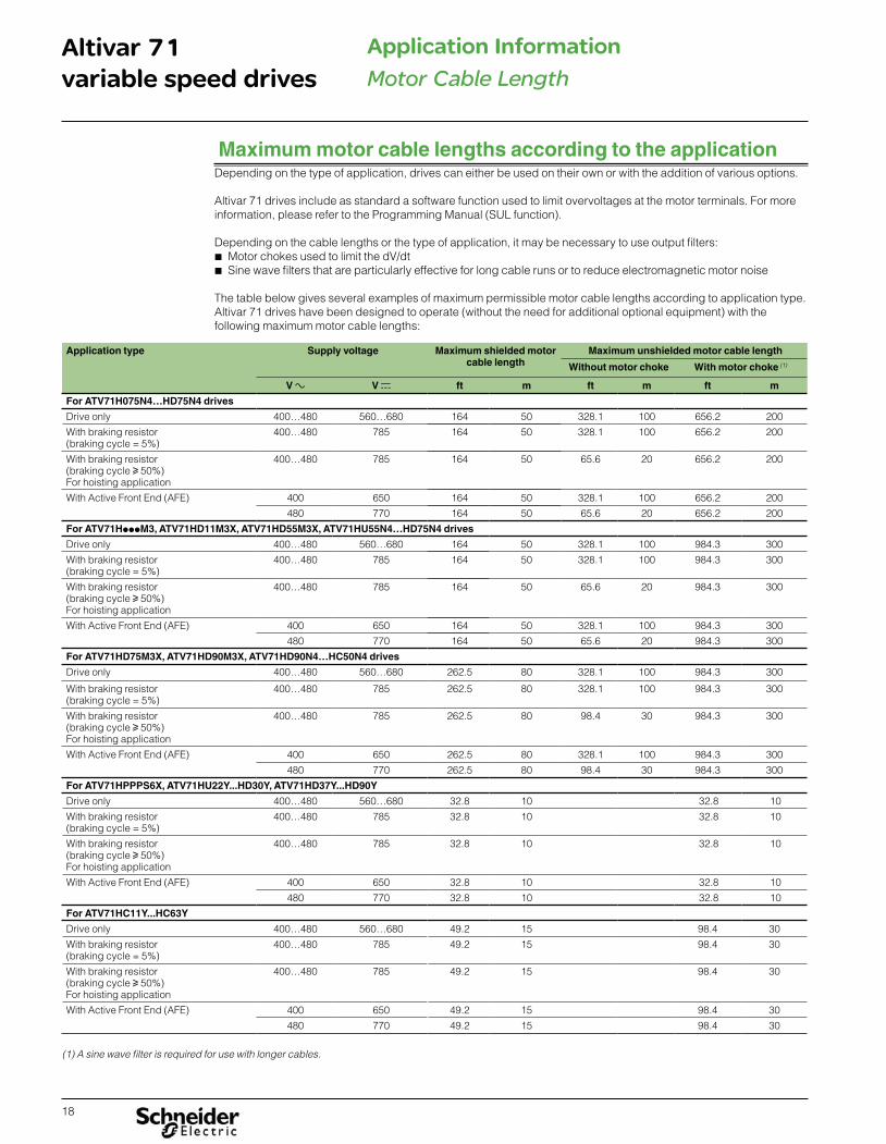
(1) This column shows the maximum prospective short circuit current value that cannot be exceeded without adding input impedance. Electrical distribution systems with a higher prospective short circuit current will cause higher input currents in the front end of the drive. It is possible for the tested SCCR rating of the drive to be lower than this Input rating. The tested SCCR rating can be higher than this input rating when a line reactor is used.(2) An ATV71 output short circuit test was performed for 100 kA. In addition to providing a rating based on shorting the output of the drive, these short circuit rating have been obtained by shorting components internal to the Altivar 71. These ratings allow proper coordination of short circuit protection. The integral solid state short circuit protection in the drive does not provide branch circuit protection. Branch circuit protection must be provided in accordance with the National Electrical Code and any local codes. The listed line reactor or minimum impedance is required to obtain ratings above the Input Rating.(3) Ratings apply to an Altivar 71 mounted in a non-ventilated Type 1, 3R, 4(X) or 12 rated enclosure. Use noted ratings when using a Type 1 conduit kit. Minimum enclosure volume allows for the specified SCCR. Your application specific thermal requirements may require a larger enclosure.(4) The fuse ratings in this column are for an Altivar 71 drive installed with a VW3A92pppp Type 1 conduit kit. These fuse ratings in this column can also apply to Altivar 71 drive installed in a Type 1, 3R, 4(X) or 12 rated enclosure that has a minimum volume listed in the table.(5) Circuit breakers with lower interrupt ratings can be used within the same circuit breaker frame rating. For 200 / 240 Vac, replace with HGL or JGL for 65kA interrupt rating. For 380 / 480 Vac, replace with HGL or JGL for 35kA or HJL or JJL for 65kA interrupt rating. For 500 / 600 Vac, replace with HJL for 25kA or HGL for 18kA, or HDL for 14kA interrupt rating.(6) 480 V ratings are for Wye connected electrical distribution systems only. GV2Ppp self protected manual combination starter must be used with GV2GH7 insulating barrier to meet UL 508 Type E rating GV3Ppp self protected manual combination starter must be used with GV3G66 + GVAM11 insulating barrier to meet UL 508 Type E rating(7) Use fast acting fuse or time delay Class J(8) Fuse type Class CC
Altivar 71 Short Circuit Current Ratings (2)
with Circuit Breaker (3) with GVpP (3) with Fuses (3) with Fuses and Type 1 kit (4)
Inp
ut V
olt
age
50/6
0 H
z Y
(HP
)
(kW
)
(A)
Par
t n
um
ber
Inp
ut
Rat
ing
: (kA
) (1
)
Min
imu
m
Ind
uct
ance
(m
H)
Lin
e R
eact
or
Ref
eren
ce
Po
wer
Pac
t (5
)
Z1,
Z2
SC
CR
(kA
) X
Min
imu
m E
ncl
osu
reVo
lum
e (i
n3 )
GV
pP
Typ
e E
(6)
Z1,
Z2
GV
pP
Vo
ltag
eR
atin
g (
V)
GV
pP
Max
imu
mP
ow
er (
HP
)
SC
CR
(kA
) X
Min
imu
m e
ncl
osu
reVo
lum
e (i
n3 )
Fu
se A
mp
ere
Rat
ing
(A
) Z
1, Z
2
SC
CR
(kA
) X
Min
imu
m e
ncl
osu
reVo
lum
e (i
n3 )
Fu
se A
mp
ere
Rat
ing
(A
) Z
1, Z
2
SC
CR
(kA
) X
Min
imu
m e
ncl
osu
reVo
lum
e (i
n3 )
Single-phase Input, without line reactor
200/
240V
sin
gle
-ph
ase
0.5 0.37 3 ATV71H075M3 5 - - HJL36015 5 4017 - - - 5 1600 15 (7) 5 1078 15 (7) 5 1078
1 0.75 4.8 ATV71HU15M3 5 - - HJL36025 5 4017 GV2P14 240 1 5 1600 25 (7) 5 1078 25 (7) 5 1078
2 1.5 8 ATV71HU22M3 5 - - HJL36035 5 4017 GV3P18 240 3 5 4017 35 (7) 5 1550 25 (7) 5 1550
3 2.2 11 ATV71HU30M3 5 - - HJL36035 5 4017 GV3P18 240 3 5 1920 35 (7) 5 1550 40 (7) 5 1550
5 4 17.5 ATV71HU75M3 5 - - HJL36110 5 6528 GV3P50 240 7.5 5 4032 110 (7) 5 2719 70 (7) 5 2719
7.5 6 27.5 ATV71HD15M3X 5 - - HJL36150 5 6528 GV3P65 240 10 5 5760 150 (7) 5 4036 110 (7) 5 4036
10 8 33 ATV71HD18M3X 5 - - JJL36175 5 13215 - - - - - 175 (7) 5 4900 125 (7) 5 4900
15 11 54 ATV71HD30M3X 5 - - JJL36250 5 13215 - - - - - 250 (7) 5 9640 200 (7) 5 9640
20 15 66 ATV71HD37M3X 5 - - JJL36250 5 13215 - - - - - 250 (7) 5 9640 225 (7) 5 9640
25 18 75 ATV71HD45M3X 10 - - - - - - - - - - 300 (7) 10 9640 300 (7) 10 9640
Single-phase input, with line reactor
200/
240V
Sin
gle
- p
has
e - 3 13.7 ATV71HU40M3 5 1 RL02502 HJL36060 5 6528 GV3P25 240 3 5 1920 60 (7) 5 1550 45 (7) 5 1550
5 4 17.5 ATV71HU55M3 5 0.8 RL03502 HJL36080 5 6528 GV3P40 240 5 5 2880 80 (7) 5 1987 60 (7) 5 1987
7.5 6 27.5 ATV71HU75M3 22 0.5 RL05502 HJL36110 22 6528 GV3P50 240 7.5 22 4032 110 (7) 22 2719 70 (7) 22 2719
8 8 33 ATV71HD15M3X 22 0.4 RL08002 HJL36150 22 6528 GV3P65 240 10 22 5760 150 (7) 22 4036 110 (7) 22 4036
15 11 54 ATV71HD22M3X 22 0.3 RL10002 JJL36200 22 13215 - - - - - 200 (7) 22 4900 150 (7) 22 4900
20 15 66 ATV71HD30M3X 22 0.2 RL13002 JJL36250 22 13215 - - - - - 250 (7) 22 9640 200 (7) 22 9640
25 18 75 ATV71HD37M3X 22 0.15 RL16002 JJL36250 22 13215 - - - - - 250 (7) 22 9640 225 (7) 22 9640
30 22 88 ATV71HD45M3X 22 0.185 RL20003B14 LAL36400 22 8640 - - - - - 300 (7) 22 9640 300 (7) 22 9640
Short Circuit Current Ratings and branch circuit protectionThe combinations in the tables have been tested per UL508C (Reference UL file E116875).These ratings are in addition to ratings on the nameplate of the product.The values for the overcurrent protection devices are the maximum allowable amp size. Smaller amp ratings may be used.Integral solid state short circuit protection does not provide branch circuit protection. Branch circuit protection must be provided in accordance with the National Electrical Code and any additional local codes.The devices are provided with software integral overload and over speed protection for the motor. Protection at 110% of the full load motor current. The motor thermal protection current (ItH) must be set to the rated current indicated on the motor nameplate. (For detail see the programming manual).75°C (167 °F) copper conductor with the AWG wire size for all products, except ATV71HC13N4p to ATV71HC50N4p, ATV71HC11Y to ATV71HC63Y: 60°C (140°F) / 75°C (167 °F) copper conductor with the AWG wire size.Suitable for use on a circuit capable of delivering not more than___X___rms symmetrical kiloAmperes,___Y___Volts maximum, when protected by___Z1___with a maximum rating of___Z2___.

24
Altivar 71variable speed drives
Short Circuit Current Ratings
Footnotes page 23
Altivar 71 Short Circuit Current Ratings (2)
with Circuit Breaker (3) with GVpP (3) with Fuses (3) with Fuses and Type 1 kit (4)
Inp
ut V
olt
age
50/6
0 H
z Y
(HP
)
(kW
)
(A)
Par
t n
um
ber
Inp
ut
Rat
ing
: (kA
) (1
)
Min
imu
m
Ind
uct
ance
(m
H)
Lin
e R
eact
or
Ref
eren
ce
Po
wer
Pac
t (5
)
Z1,
Z2
SC
CR
(kA
) X
Min
imu
m E
ncl
osu
reVo
lum
e (i
n3 )
GV
pP
Typ
e E
(6)
Z1,
Z2
GV
pP
Volt
age
Rat
ing
(V
)
GV
pP
Max
imu
mP
ow
er (
HP
)
SC
CR
(kA
) X
Min
imu
m e
ncl
osu
reVo
lum
e (i
n3 )
Fu
se A
mp
ere
Rat
ing
(A)
Z1,
Z2
SC
CR
(kA
) X
Min
imu
men
clo
sure
Volu
me
(in
3 )
Fu
se A
mp
ere
Rat
ing
(A)
Z1,
Z2
SC
CR
(kA
) X
Min
imu
m e
ncl
osu
reVo
lum
e (i
n3 )
Three-phase Input, without line reactor
200/
240
V T
hre
e-p
has
e
0.5 0.37 3 ATV71H037M3 5 - - HJL36015 5 4017 GV2P08 240 1 5 1600 15 (7) 5 4017 7 (8) 5 1078
1 0.75 4.8 ATV71H075M3 5 - - HJL36015 5 4017 GV2P10 240 1.5 5 1600 15 (7) 5 4017 15 (7) 5 1078
2 1.5 8 ATV71HU15M3 5 - - HJL36025 5 4017 GV2P14 240 3 5 1600 25 (7) 5 4017 25 (7) 5 1078
3 2.2 11 ATV71HU22M3 5 - - HJL36035 5 4017 GV3P18 240 5 5 1920 35 (7) 5 4017 25 (7) 5 1550
- 3 13.7 ATV71HU30M3 5 - - HJL36035 5 4017 GV3P18 240 3 5 1920 35 (7) 5 4017 40 (7) 5 1550
5 4 17.5 ATV71HU40M3 5 - - HJL36060 5 4017 GV3P25 240 7.5 5 1920 60 (7) 5 4017 45 (7) 5 1550
7.5 6 27.5 ATV71HU55M3 22 - - HJL36080 22 6528 GV3P40 240 10 5 2880 80 (7) 22 6528 60 (7) 5 1987
10 8 33 ATV71HU75M3 22 - - HJL36110 22 6528 GV3P50 240 10 5 4032 110 (7) 22 6528 70 (7) 5 2719
15 11 54 ATV71HD11M3X 22 - - HJL36110 22 6528 GV3P50 240 10 5 5760 110 (7) 22 6528 90 (7) 5 4036
20 15 66 ATV71HD15M3X 22 - - HJL36150 22 6528 GV3P65 240 15 5 5760 150 (7) 22 6528 110 (7) 5 4036
25 18 75 ATV71HD18M3X 22 - - JJL36175 22 13215 - - - - - 175 (7) 22 13215 125 (7) 5 4900
30 22 88 ATV71HD22M3X 22 - - JJL36200 22 13215 - - - - - 200 (7) 22 13215 150 (7) 5 4900
40 30 120 ATV71HD30M3X 22 - - JJL36250 22 13215 - - - - - 250 (7) 22 13215 200 (7) 5 9640
50 37 144 ATV71HD37M3X 22 - - JJL36250 22 13215 - - - - - 250 (7) 22 13215 225 (7) 5 9640
60 45 176 ATV71HD45M3X 22 - - - - - - - - - - - - - 300 (7) 10 9640
380/
480V
Th
ree-
ph
ase
1 0.75 2.3 ATV71H075N4 5 - - HLL36015 5 4017 GV2P08 480Y/277 2 5 1600 15 (8) 5 4017 6 (8) 5 1078
2 1.5 4.1 ATV71HU15N4 5 - - HLL36015 5 4017 GV2P10 480Y/277 4 5 1600 15 (8) 5 4017 12 (8) 5 1078
3 2.2 5.8 ATV71HU22N4 5 - - HLL36015 5 4017 GV2P14 480Y/277 5 5 1600 15 (7) 5 4017 15 (7) 5 1078
- 3 7.8 ATV71HU30N4 5 - - HLL36015 5 4017 GV2P14 480Y/277 5 5 1920 15 (7) 5 4017 17.5 (7) 5 1550
5 4 10.5 ATV71HU40N4 5 - - HLL36025 5 4017 GV3P13 480Y/277 7.5 5 1920 25 (7) 5 4017 25 (7) 5 1550
7.5 5.5 14.3 ATV71HU55N4 22 - - HLL36040 22 6528 GV3P25 480Y/277 15 5 2880 40 (7) 22 6528 40 (7) 5 1987
10 7.5 17.6 ATV71HU75N4 22 - - HLL36050 22 6528 GV3P25 480Y/277 15 5 2880 50 (7) 22 6528 40 (7) 5 1987
15 11 27.7 ATV71HD11N4 22 - - HLL36070 22 6528 GV3P40 480Y/277 25 5 4032 70 (7) 22 6528 60 (7) 5 2719
20 15 33 ATV71HD15N4 22 - - HLL36100 22 6528 GV3P50 480Y/277 30 5 5760 100 (7) 22 6528 70 (7) 5 4036
25 18 41 ATV71HD18N4 22 - - HLL36090 22 6528 GV3P50 480Y/277 30 5 8640 90 (7) 22 6528 70 (7) 5 4036
30 22 48 ATV71HD22N4 22 - - HLL36100 22 6528 GV3P50 480Y/277 30 5 8640 100 (7) 22 6528 80 (7) 5 4900
40 30 66 ATV71HD30N4 22 - - HLL36125 22 6528 GV3P65 480Y/277 40 5 10368 125 (7) 22 6528 90 (7) 5 7230
50 37 79 ATV71HD37N4 22 - - HLL36150 22 13215 - - - - - 150 (7) 22 13215 110 (7) 5 7230
60 45 94 ATV71HD45N4 22 - - JLL36200 22 13215 - - - - - 200 (7) 22 13215 150 (7) 10 12044
75 55 116 ATV71HD55N4 22 - - JLL36225 22 13215 - - - - - 225 (7) 22 13215 175 (7) 10 12044
100 75 160 ATV71HD75N4 22 - - JLL36250 22 38250 - - - - - 250 (7) 22 38250 225 (7) 10 12044
100 75 160 ATV71HD75N4 22 - - KCL34250 22 38250 - - - - - 250 (7) 22 38250 225 (7) 10 12044

25
Altivar 71variable speed drives
Short Circuit Current Ratings
Altivar 71 Short Circuit Current Ratings (2)
with Circuit Breaker (3) with GVpP (3) with Fuses (3) with Fuses and Type 1 kit (4)
Inp
ut
Vo
ltag
e50
/60
Hz
Y
(HP
)
(kW
)
(A)
Par
t n
um
ber
Inp
ut
Rat
ing
: (kA
) (1
)
Min
imu
m In
du
ctan
ce(m
H)
Lin
e R
eact
or
Ref
eren
ce
Po
wer
Pac
t (5
)
Z1,
Z2
SC
CR
(kA
) X
Min
imu
m E
ncl
osu
reVo
lum
e (i
n3 )
GV
pP
Typ
e E
(6)
Z1,
Z2
GV
pP
Vo
ltag
eR
atin
g (
V)
GV
pP
Max
imu
mP
ow
er (
HP
)
SC
CR
(kA
) X
Min
imu
m e
ncl
osu
reVo
lum
e (i
n3 )
Fu
se A
mp
ere
Rat
ing
(A
) Z
1, Z
2
SC
CR
(kA
) X
Min
imu
m e
ncl
osu
reVo
lum
e (i
n3 )
Fu
se A
mp
ere
Rat
ing
(A
) Z
1, Z
2
SC
CR
(kA
) X
Min
imu
m e
ncl
osu
reVo
lum
e (i
n3 )
Three-phase Input, without line reactor
575V
Th
ree-
ph
ase
2 1.5 2.7 ATV71HU15S6X 22 - - - - - - - - - - 6 (7) 22 3898 10 (7) 22 3898
3 2.2 3.9 ATV71HU22S6X 22 - - - - - - - - - - 6 (7) 22 3898 10 (7) 22 3898
- 3 5.8 ATV71HU30S6X 22 - - - - - - - - - - 6 (7) 22 3898 15 (7) 22 3898
5 4 6.1 ATV71HU40S6X 22 - - - - - - - - - - 10 (7) 22 3898 15 (7) 22 3898
7.5 5.5 9 ATV71HU55S6X 22 - - - - - - - - - - 15 (7) 22 3898 20 (7) 22 3898
10 7.5 11 ATV71HU75S6X 22 - - - - - - - - - - 20 (7) 22 3898 25 (7) 22 3898
500/
600V
Th
ree-
ph
ase
2 1.5 2.7 ATV71HU22Y 22 - - - - - - - - - - - - - 10 (7) 22 8640
3 2.2 3.9 ATV71HU30Y 22 - - - - - - - - - - - - - 10 (7) 22 8640
- 3 5.8 ATV71HU40Y 22 - - - - - - - - - - - - - 10 (7) 22 8640
5 4 6.1 ATV71HU55Y 22 - - - - - - - - - - - - - 15 (7) 22 8640
7.5 5.5 9 ATV71HU75Y 22 - - - - - - - - - - - - - 20 (7) 22 8640
10 7.5 11 ATV71HD11Y 22 - - - - - - - - - - - - - 25 (7) 22 8640
15 11 17 ATV71HD15Y 22 - - - - - - - - - - - - - 35 (7) 22 8640
20 15 22 ATV71HD18Y 22 - - - - - - - - - - - - - 45 (7) 22 8640
25 18.5 27 ATV71HD22Y 22 - - - - - - - - - - - - - 60 (7) 22 8640
30 22 32 ATV71HD30Y 22 - - - - - - - - - - - - - 60 (7) 22 8640
40 30 41 ATV71HD37Y 22 - - - - - - - - - - - - - 90 (7) 22 9792
50 37 52 ATV71HD45Y 22 - - - - - - - - - - - - - 100 (7) 22 9792
60 45 62 ATV71HD55Y 22 - - - - - - - - - - - - - 125 (7) 22 9792
75 55 77 ATV71HD75Y 22 - - - - - - - - - - - - - 150 (7) 22 9792
100 75 99 ATV71HD90Y 22 - - - - - - - - - - - - - 175 (7) 22 9792
Three-phase Input, with line reactor
200/
240V
Th
re-p
has
e
0.5 0.37 3 ATV71H037M3 5 3 RL00401 HJL36015 100 4017 GV2P08 240 1 65 1600 15 (7) 100 4017 7 (8) 5 1078
1 0.75 4.8 ATV71H075M3 5 1.5 RL00401 HJL36015 100 4017 GV2P10 240 1.5 65 1600 15 (7) 100 4017 15 (7) 5 1078
2 1.5 8 ATV71HU15M3 5 1.25 RL00801 HJL36025 100 4017 GV2P14 240 3 65 1600 25 (7) 100 4017 25 (7) 5 1078
3 2.2 11 ATV71HU22M3 5 0.8 RL01201 HJL36035 100 4017 GV3P18 240 5 65 1920 35 (7) 100 4017 25 (7) 5 1550
- 3 13.7 ATV71HU30M3 5 0.8 RL01801 HJL36035 100 4017 GV3P18 240 5 65 1920 35 (7) 100 4017 40 (7) 5 1550
5 4 17.5 ATV71HU40M3 5 0.5 RL01801 HJL36060 100 4017 GV3P25 240 7.5 65 1920 60 (7) 100 4017 45 (7) 5 1550
7.5 6 27.5 ATV71HU55M3 22 0.4 RL02501 HJL36080 100 6528 GV3P40 240 10 65 2880 80 (7) 100 6528 60 (7) 5 1987
10 8 33 ATV71HU75M3 22 0.3 RL03501 HJL36110 100 6528 GV3P50 240 10 65 4032 110 (7) 100 6528 70 (7) 5 2719
15 11 54 ATV71HD11M3X 22 0.25 RL04501 HJL36110 100 6528 GV3P50 240 10 65 5760 110 (7) 100 6528 90 (7) 5 4036
20 15 66 ATV71HD15M3X 22 0.2 RL05501 HJL36150 100 6528 GV3P65 240 15 65 5760 150 (7) 100 6528 110 (7) 5 4036
25 18 75 ATV71HD18M3X 22 0.15 RL08001 JJL36175 100 13215 - - - - - 175 (7) 100 13215 125 (7) 5 4900
30 22 88 ATV71HD22M3X 22 0.1 RL10001 JJL36200 100 13215 - - - - - 200 (7) 100 13215 150 (7) 5 4900
40 30 120 ATV71HD30M3X 22 0.075 RL13001 JJL36250 100 13215 - - - - - 250 (7) 100 13215 200 (7) 5 9640
50 37 144 ATV71HD37M3X 22 0.055 RL16001 JJL36250 100 13215 - - - - - 250 (7) 100 13215 225 (7) 5 9640
60 45 176 ATV71HD45M3X 22 0.055 RL20001 LAL36400 22 8640 - - - - - 400 (7) 22 8640 300 (7) 10 9640
Footnotes page 23
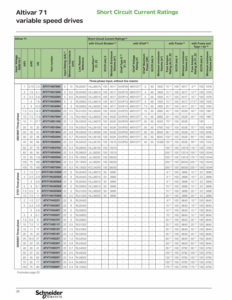
26
Altivar 71variable speed drives
Short Circuit Current Ratings
Altivar 71 Short Circuit Current Ratings (2)
with Circuit Breaker (3) with GVpP (3) with Fuses (3) with Fuses and Type 1 kit (4)
Inp
ut
Vo
ltag
e50
/60
Hz
Y
(HP
)
(kW
)
(A)
Par
t n
um
ber
Inp
ut
Rat
ing
: (kA
) (1)
Min
imu
m In
du
ctan
ce(m
H)
Lin
e R
eact
or
Ref
eren
ce
Po
wer
Pac
t (5
)
Z1,
Z2
SC
CR
(kA
) X
Min
imu
m E
ncl
osu
reVo
lum
e (i
n3 )
GV
pP
Typ
e E
(6)
Z1,
Z2
GV
pP
Vo
ltag
eR
atin
g (
V)
GV
pP
Max
imu
mP
ow
er (
HP
)
SC
CR
(kA
) X
Min
imu
m e
ncl
osu
reVo
lum
e (i
n3 )
Fu
se A
mp
ere
Rat
ing
(A
) Z
1, Z
2
SC
CR
(kA
) X
Min
imu
m e
ncl
osu
reVo
lum
e (i
n3 )
Fu
se A
mp
ere
Rat
ing
(A
) Z
1, Z
2
SC
CR
(kA
) X
Min
imu
m e
ncl
osu
reVo
lum
e (i
n3 )
Three-phase Input, without line reactor
380/
480V
Th
ree-
ph
ase
1 0.75 2.3 ATV71H075N4 5 12 RL00201 HLL36015 100 4017 GV2P08 480Y/277 2 65 1600 15 (7) 100 4017 6 (8) 100 1078
2 1.5 4.1 ATV71HU15N4 5 6.5 RL00402 HLL36015 100 4017 GV2P10 480Y/277 4 65 1600 15 (7) 100 4017 12 (8) 100 1078
3 2.2 5.8 ATV71HU22N4 5 6.5 RL00402 HLL36015 100 4017 GV2P14 480Y/277 5 65 1600 15 (7) 100 4017 15 (7) 100 1078
- 3 7.8 ATV71HU30N4 5 3 RL00802 HLL36015 100 4017 GV2P14 480Y/277 5 65 1920 15 (7) 100 4017 17.5 (7) 100 1550
5 4 10.5 ATV71HU40N4 5 3 RL00802 HLL36025 100 4017 GV3P13 480Y/277 7.5 65 1920 25 (7) 100 4017 25 (7) 100 1550
7.5 5.5 14.3 ATV71HU55N4 22 2.5 RL01202 HLL36040 100 6528 GV3P25 480Y/277 15 65 2880 40 (7) 100 6528 40 (7) 100 1987
10 7.5 17.6 ATV71HU75N4 22 1.5 RL01802 HLL36050 100 6528 GV3P25 480Y/277 15 65 2880 50 (7) 100 6528 40 (7) 100 1987
15 11 27.7 ATV71HD11N4 22 1.2 RL02502 HLL36070 100 6528 GV3P40 480Y/277 25 65 4032 70 (7) 100 6528 - 100 -
20 15 33 ATV71HD15N4 22 0.8 RL03502 HLL36100 100 6528 GV3P50 480Y/277 30 65 5760 100 (7) 100 6528 70 (7) 100 4036
25 18 41 ATV71HD18N4 22 0.8 RL03502 HLL36090 100 6528 GV3P50 480Y/277 30 65 8640 90 (7) 100 6528 70 (7) 100 4036
30 22 48 ATV71HD22N4 22 0.7 RL04502 HLL36100 100 6528 GV3P50 480Y/277 30 65 8640 100 (7) 100 6528 80 (7) 100 4900
40 30 66 ATV71HD30N4 22 0.5 RL05502 HLL36125 100 13215 GV3P65 480Y/277 40 65 10368 125 (7) 100 6528 90 (7) 100 7230
50 37 79 ATV71HD37N4 22 0.4 RL08002 HLL36150 100 13215 - - - - - 150 (7) 100 13215 110 (7) 100 7230
60 45 94 ATV71HD45N4 22 0.4 RL08002 JLL36200 100 13215 - - - - - 200 (7) 100 13215 150 (7) 100 12044
75 55 116 ATV71HD55N4 22 0.3 RL10002 JLL36225 100 38250 - - - - - 225 (7) 100 13215 175 (7) 100 12044
100 75 160 ATV71HD75N4 22 0.2 RL13002 JLL36250 100 38250 - - - - - 250 (7) 100 38250 225 (7) 100 12044
100 75 160 ATV71HD75N4 22 0.2 RL13002 KCL34250 100 38250 - - - - - 250 (7) 100 38250 225 (7) 100 12044
575V
Th
ree-
ph
ase 2 1.5 2.7 ATV71HU15S6X 22 9 RL00403 HLL36015 50 3898 - - - - - 6 (7) 100 3898 10 (7) 22 3898
3 2.2 3.9 ATV71HU22S6X 22 9 RL00403 HLL36015 50 3898 - - - - - 6 (7) 100 3898 10 (7) 22 3898
- 3 5.8 ATV71HU30S6X 22 9 RL00403 HLL36015 50 3898 - - - - - 6 (7) 100 3898 15 (7) 22 3898
5 4 6.1 ATV71HU40S6X 22 5 RL00803 HLL36015 50 3898 - - - - - 10 (7) 100 3898 15 (7) 22 3898
7.5 5.5 9 ATV71HU55S6X 22 3 RL01203 HLL36020 50 3898 - - - - - 15 (7) 100 3898 20 (7) 22 3898
10 7.5 11 ATV71HU75S6X 22 2.5 RL01203 HLL36025 50 3898 - - - - - 20 (7) 100 3898 25 (7) 22 3898
500/
600V
Th
ree-
ph
ase
2 1.5 2.7 ATV71HU22Y 22 9 RL00403 - - - - - - - - 6 (8) 100 8640 10 (7) 100 8640
3 2.2 3.9 ATV71HU30Y 22 9 RL00403 - - - - - - - - 10 (7) 100 8640 10 (7) 100 8640
- 3 5.8 ATV71HU40Y 22 5 RL00803 - - - - - - - - 10 (7) 100 8640 15 (7) 100 8640
5 4 6.1 ATV71HU55Y 22 5 RL00803 - - - - - - - - 15 (7) 100 8640 15 (7) 100 8640
7.5 5.5 9 ATV71HU75Y 22 3 RL00802 - - - - - - - - 20 (7) 100 8640 20 (7) 100 8640
10 7.5 11 ATV71HD11Y 22 2.5 RL01202 - - - - - - - - 25 (7) 100 8640 25 (7) 100 8640
15 11 17 ATV71HD15Y 22 1.5 RL01802 - - - - - - - - 35 (7) 100 8640 35 (7) 100 8640
20 15 22 ATV71HD18Y 22 1.2 RL02502 - - - - - - - - 45 (7) 100 8640 45 (7) 100 8640
25 18.5 27 ATV71HD22Y 22 1.2 RL02502 - - - - - - - - 60 (7) 100 8640 60 (7) 100 8640
30 22 32 ATV71HD30Y 22 0.8 RL03502 - - - - - - - - 60 (7) 100 8640 60 (7) 100 8640
40 30 41 ATV71HD37Y 22 0.7 RL04502 - - - - - - - - 90 (7) 100 9792 90 (7) 100 9792
50 37 52 ATV71HD45Y 22 0.5 RL05502 - - - - - - - - 100 (7) 100 9792 100 (7) 100 9792
60 45 62 ATV71HD55Y 22 0.4 RL08002 - - - - - - - - 125 (7) 100 9792 125 (7) 100 9792
75 55 77 ATV71HD75Y 22 0.4 RL08002 - - - - - - - - 150 (7) 100 9792 150 (7) 100 9792
100 75 99 ATV71HD90Y 22 0.3 RL10002 - - - - - - - - 175 (7) 100 9792 175 (7) 100 9792
Footnotes page 23

27
Altivar 71variable speed drives
Short Circuit Current Ratings
Altivar 71 Short Circuit Current Ratings (2)
with Circuit Breaker
(3)with GVpP (3) with Fuses (3) with Fuses and
Type 1 kit (4)
Inp
ut
Vo
ltag
e50
/60
Hz
Y
(HP
)
(kW
)
(A)
Par
t n
um
ber
Inp
ut
Rat
ing
: (kA
) (1)
Min
imu
m In
du
ctan
ce(m
H)
Lin
e R
eact
or
Ref
eren
ce
Po
wer
Pac
t (1
0)
Z1,
Z2
SC
CR
(kA
) X
Min
imu
m E
ncl
osu
reVo
lum
e (i
n3 )
GV
pP
Typ
e E
6 Z
1, Z
2
GV
pP
Vo
ltag
eR
atin
g (
V)
GV
pP
Max
imu
mP
ow
er (
HP
)S
CC
R (
kA)
X
Min
imu
m e
ncl
osu
reVo
lum
e (i
n3 )
Fu
se A
mp
ere
Rat
ing
(A
) Z
1, Z
2
SC
CR
(kA
) X
Min
imu
m e
ncl
osu
reVo
lum
e (i
n3 )
Fu
se A
mp
ere
Rat
ing
(A
) Z
1, Z
2
SC
CR
(kA
) X
Min
imu
m e
ncl
osu
reVo
lum
e (i
n3 )
Three-phase Input, without line reactor
200/
240V
T
hre
e-p
has
e 75 55 221 ATV71HD55M3X 35 - - - - - - - - - - 350 (6) 10 22749 350 (6) 10 22749
100 75 285 ATV71HD75M3X 35 - - - - - - - - - - 450 (6) 10 28416 450 (6) 10 28416
380/
480V
Th
ree-
ph
ase
125 90 179 ATV71HD90N4 35 - - - - - - - - - - 300 (6) 35 45900 250 (6) 10 22749
150 110 215 ATV71HC11N4 35 - - - - - - - - - - 300 (6) 35 45900 300 (6) 10 28416
200 132 259 ATV71HC13N4 35 - - - - - - - - - - 400 (6) 35 45900 350 (6) 10 31117
250 160 314 ATV71HC16N4 50 - - - - - - - - - - 400 (5) 50 45900 400 (6) 18 40250
300 200 387 ATV71HC20N4 50 - - - - - - - - - - 500 (5) 50 53550 500 (6) 18 54450
400 250 481 ATV71HC25N4 50 - - - - - - - - - - 600 (5) 50 53550 600 (6) 18 54450
450 280 550 ATV71HC28N4 50 - - - - - - - - - - 600 (5) 50 53550 700 (6) 30 54450
500 315 616 ATV71HC31N4 30 - - - - - - - - - - 800 (7) 30 95579 - - -
600 400 759 ATV71HC40N4 30 - - - - - - - - - - 2 x 500 6, 9 30 95579 - - -
700 500 941 ATV71HC50N4 42 - - - - - - - - - - 2 x 600 6, 9 42 120265 - - -
Three-phase input, with line reactor
200/
240V
T
hre
-ph
ase 75 55 221 ATV71HD55M3Xp
(8)35 0.045 RL25001 - - - - - - - - 350 (6) 10 22749 350 (6) 10 22749
100 75 285 ATV71HD75M3Xp (8)
35 0.04 RL32001 - - - - - - - - 450 (6) 10 28416 450 (6) 10 28416
380/
480V
Th
ree-
ph
ase
125 90 179 ATV71HD90N4p (8) 35 0.15 RL16002 LLL36400 100 43200 - - - - - 300 (6) 100 43200 250 (6) 10 22749
150 110 215 ATV71HC11N4p (8) 35 0.11 RL20002 LLL36400 100 43200 - - - - - 300 (6) 100 43200 300 (6) 10 28416
200 132 259 ATV71HC13N4p (8) 35 0.09 RL25002 LLL36400 100 43200 - - - - - 400 (6) 100 43200 350 (6) 10 31117
250 160 314 ATV71HC16N4p (8) 50 0.075 RL32002 - - - - - - - - 400 (5) 100 45900 400 (6) 18 40250
300 200 387 ATV71HC20N4p (8) 50 0.06 RL40002 - - - - - - - - 500 (5) 100 53550 500 (6) 18 54450
400 250 481 ATV71HC25N4p (8) 50 0.05 RL50002 - - - - - - - - 600 (5) 100 53550 600 (6) 18 54450
450 280 550 ATV71HC28N4p (8) 50 0.04 RL60002 - - - - - - - - 600 (5) 100 53550 700 (7) 30 54450
500 315 616 ATV71HC31N4p (8) 30 0.04 RL60002 - - - - - - - - 800 (7) 100 95579 - - -
600 400 759 ATV71HC40N4p (8) 30 0.03 2 x RL40002B14 (9) - - - - - - - - 2 x 500 (6, 9)
100 95579 - - -
700 500 941 ATV71HC50N4p (8) 42 0.025 2 x RL50002 (9) - - - - - - - - 2 x 600 (6, 9)
100 120265 - - -
500/
600V
Th
ree-
ph
ase
125 110 125 ATV71HC11Y 28 0.2 RL13002 - - - - - - - - 200 (6) 100 31117 200 (6) 28 31117
150 132 150 ATV71HC13Y 28 0.15 RL16002 - - - - - - - - 200 (6) 100 31117 200 (6) 28 31117
- 160 180 ATV71HC16Y 35 0.11 RL20002 - - - - - - - - 250 (6) 100 31117 250 (6) 35 31117
200 200 200/
220
ATV71HC20Y 35 0.11 RL20002 - - - - - - - - 300 (6) 100 54450 300 (6) 35 54450
250 250 290 ATV71HC25Y 35 0.09 RL25002 - - - - - - - - 400 (6) 100 54450 400 (6) 35 54450
350 315 355 ATV71HC31Y 35 0.06 RL40002 - - - - - - - - 500 (6) 100 54450 500 (6) 35 54450
450 400 420 ATV71HC40Y 42 0.045 2 x RL25002B14 (9) - - - - - - - - 2 x 300 (6, 9)
100 120265 - - -
550 500 543 ATV71HC50Y 42 0.0375 2 x RL32002B14 (9) - - - - - - - - 2 x 400 (6, 9)
100 120265 - - -
700 630 675 ATV71HC63Y 42 0.03 2 x RL40002B14 (9) - - - - - - - - 2x 500 (6, 9)
100 120265 - - -
Footnotes page 28

28
Altivar 71variable speed drives
Short Circuit Current Ratings
(1) This column shows the maximum prospective short circuit current value that cannot be exceeded without adding input impedance. Electrical distribution systems with a higher prospective short circuit current will cause higher input currents in the front end of the drive. It is possible for the tested SCCR rating of the drive to be lower than this Input rating. The tested SCCR rating can be higher than this input rating when a line reactor is used. Add the inductance referred in the table at the input of the drive if installing the drive on a system with higher prospective short circuit current. A 3% (minimum) input line reactor or equivalent inductance is required for the 500..600 Vac Altivar 71s and provides the listed value with the listed fuse protection.(2) An ATV71 output short circuit test was performed for 100 kA. In addition to providing a rating based on shorting the output of the drive, these short circuit rating have been obtained by shorting components internal to the Altivar 71. These ratings allow proper coordination of short circuit protection.Note: The integral solid state short circuit protection in the drive does not provide branch circuit protection. Branch circuit protection must be provided in accordance with the National Electrical Code and any local codes. The listed line reactor or minimum impedance is required to obtain ratings above the Input Rating.(3) Ratings apply to an Altivar 71 mounted in a non-ventilated Type 1, 3R, 4(X) or 12 rated enclosure. Use noted ratings when using a Type 1 kit. Minimum enclosure volume allows for the specified SCCR. Your application specific thermal requirements may require a larger enclosure.(4) The fuse ratings in this column are for an Altivar 71 drive installed with a VW3A92pppp Type 1 conduit kit. Fuse type must be fast acting Class J fuses unless otherwise noted. These fuse ratings in this column can also apply to Altivar 71 drives installed in a Type 1, 3R, 4(X), or 12 rated enclosure that has a minimum volume listed in the table(5) Use Bussmann fuses Class J ref. LPJpppSP series, 600V max .(6) Fuse Class J / fast acting, 600V max.(7) Fuse Class T / fast acting, 600V max(8) Can be ordered without a DC Choke for connections to the DC BUS or when using a line reactor by adding D at the end of the reference.(9) The diagram below shows how to address drives with two rectifiers.(10) Circuit breakers with lower interrupt ratings can be used within the same circuit breaker frame rating. For 380 / 480� Vac, replace LLL with LDL for 18kA or LGL for 35kA or LJL for 65kA interrupt rating.
A: The ATV71 supply must be split up in front of the line reactors, if they are used.
B: The monitoring of the fuses is necessary to protect the inverter against unbalanced load. It must act on mains contactor or pulse inhibit (e.g. digital input “External fault”, see Programming guide)
HS: Main switch (to be used if required according to the local regulations)
NH: Mains fuses considering table “Fuse Ampere Rating” (absolutely necessary)
NS: Mains contactor (to be used if required according to the local regulations)

29
Altivar 71variable speed drives
Accessories & OptionsProduct Variant Options
Product variant optionsThe Altivar 71 is available in several variations for unique applications and needs. These variations are mutually exclusive.
For use with a synchronous motor and closed loop feedbackThe Altivar 71 includes the capability to control synchronous motors in open loop applications. When applying the Altivar 71 on a synchronous motor in a closed loop, add 383 at the end of the part number.
Example: ATV71H075N4 becomes ATV71H075N4383.
For mounting the drive in dusty and corrosive environmentsThis variant enables variable speed drives to be installed in a higher level of ambient pollution conditions and complies with standard IEC60721-3-3 class 3C2 by tinning any exposed copper.
To order this option for ATV71HpppM3 and ATV71H075N4…HD75N4 variable speed drives, add S337 at the end of the part number.Example: ATV71H075M3 becomes ATV71H075M3S337.
To order this option for ATV71HD11M3X…HD45M3X drives, add 337 at the end of the part number. Example: ATV71HD11M3X becomes ATV71HD11M3X337.
The following list of drives already have exposed copper tinned and comply with IEC 60721-3-3 class 3C2:
� ATV71HD55M3X, HD75M3X � ATV71HD90N4... HC50N4 � All ATV71H...Y
This variant is supplied with the graphic display keypad.
Ordering without the graphic display keypadAll Altivar 71 drives come with a graphic display keypad and an integrated keypad display as standard.
ATV71H037M3…HD15M3X and ATV71H075N4…HD75N4 drives can be ordered without the graphic display keypad. They will then have the integrated kepyad display only.
Without the graphic display keypad installed, a 4 button keypad and 4 digit, 7 segment display is visible. In this case, add Z at the end of the reference. Example: ATV71H075M3 becomes ATV71H075M3Z.
Order the drive without a DC chokeATV71HD90N4…HC50N4 drives are supplied as standard with a DC choke which must be field mounted when installing drives to the three-phase supply.
These drives can be ordered without a DC choke for connections to the DC bus or when using a line choke, by adding D at the end of the reference.Example: ATV71HD90N4 becomes ATV71HD90N4D.
ATV71HU22M3Z
ATV71H075N4383
ATV71H075M3S337

30
Altivar 71variable speed drives
Accessories & OptionsMounting Options
Control card fan kit (for ATV71Hppppp drives on heatsink) This kit is required for ATV71HD18M3X…HD45M3X, ATV71HD22N4…HD75N4 and ATV71HU22Y…HD90Y drives in order that they can operate at ambient temperatures between 50°C and 60°C, for example if they are mounted in a Type 12/ IP 54 enclosure. The circulation of air around the electronic cards prevents the formation of hot spots.
To ascertain the derating to be applied to the drive nominal current, please refer to the curves in the Installation Manual.
The kit (1) is mounted on the upper part of the drive. It is powered by the drive and includes:
b A fan subassembly b Mounting screws b A manual
thgieWrebmun traPsevird roF
lbs kg
ATV71HD18M3X, HD22M3XATV71HD22N4ATV71HU22Y…HD30Y
VW3A9404 1 .5
ATV71HD30N4, HD37N4 VW3A9405 2 .9
ATV71HD30M3X…HD45M3X VW3A9406 3 1.4
ATV71HD45N4…HD75N4ATV71HD37Y…HD90Y
VW3A9407 3 1.4
1
Control card fan kit

31
Altivar 71variable speed drives
Accessories & OptionsMounting Options
Kit for flush-mounting in a dust and damp proof enclosure (for ATV71Hppppp drives on heatsink)
This kit can be used to mount the power section of the drive outside the enclosure, which reduces the power dissipated into the enclosure (1).
It is available for ATV71HpppM3, ATV71HpppM3X, ATV71H075N4…HC28N4, ATV71HD90N4D…HC28N4D and ATV71HU22Y…HC31Y drives.
With this type of mounting, the maximum internal temperature in the enclosure can then reach 60°C without it being necessary to derate the drive. Between 50°C and 60°C, a control card fan kit must be used for ATV71HD18M3X…HD45M3X, ATV71HD22N4…HD75N4, ATV71HpppS6X and ATV71HU22Y…HD90Y drives to prevent hot spots.
The back of the enclosure must be drilled and cut out for this type of mounting.
The kit includes: b A metal frame of the right size for the drive rating b Corner pieces b Seals b A fan support (this can be used to move the fans so that they can be accessed
from the front of the enclosure) b Mounting screws b A manual
For drives Part number Weightlbs kg
ATV71H037M3…HU15M3ATV71H075N4…HU22N4
VW3A9501 6 2.7
ATV71HU22M3…HU40M3ATV71HU30N4, HU40N4
VW3A9502 6.8 3.1
ATV71HU55M3ATV71HU55N4, HU75N4
VW3A9503 8.2 3.7
ATV71HU75M3ATV71HD11N4ATV71HU15S6X…HU75S6X
VW3A9504 10.1 4.6
ATV71HD11M3X, HD15M3XATV71HD15N4, HD18N4
VW3A9505 10.8 4.9
ATV71HD18M3X, HD22M3XATV71HD22N4ATV71HU22Y…HD30Y
VW3A9506 8.6 3.9
ATV71HD30N4, HD37N4 VW3A9507 9.3 4.2
ATV71HD30M3X…HD45M3X VW3A9508 10.8 4.9
ATV71HD45N4…HD75N4ATV71HD37Y…HD90Y
VW3A9509 11.5 5.2
ATV71HD55M3X (2)
ATV71HD90N4 (2)
ATV71HD90N4D (3)
VW3A9510 11.2 5.1
ATV71HD75M3X (2)
ATV71HC11N4 (2)
ATV71HC11N4D (3)
VW3A9511 7.9 3.6
ATV71HC13N4 (2)
ATV71HC13N4D (3)
ATV71HC11Y…HC16Y (4)
VW3A9512 9.5 4.3
ATV71HC16N4 (2)
ATV71HC16N4D (3)VW3A9513 9.7 4.4
ATV71HC20N4…HC28N4 (2)
ATV71HC20N4D…HC28N4D (3)
ATV71HC20Y…HC31Y (4)
Without braking unit VW3A9514 10.4 4.7
(1) Power dissipated in the enclosure for dust and damp proof flush-mounting.(2) Drives supplied as standard with a DC choke. In this case, cut out and drill the enclosure for the choke.(3) Drives supplied without DC choke.(4) Drives supplied as standard with a transformer for the fan. In this case, cut out and drill the enclosure for the transformer.
ATV71HU75N4 flush-mounted drive
ATV71HC28N4D flush-mounted drive

32
Altivar 71variable speed drives
Accessories & Options
UL Type 1 conformance kitWhen the drive is mounted directly on a wall outside the enclosure, this kit can be used to provide UL Type 1 comformance when connecting the cables and conduit.The shielding is connected inside the kit.
For ATV71HpppM3, ATV71HD11M3X…HD45M3X, ATV71H075N4…HD75N4, ATV71HpppS6X and ATV71HU22Y…HD90Y drives, the kit includes:
b All the mechanical fittings (1) including a pre-cut plate (2) for conduit entrance (3) b Mounting screws b A manual
For ATV71HD55M3X, HD75M3X, ATV71HD90N4…HC28N4, ATV71HD90N4D…HC28N4D and ATV71HC11Y…HC31Y drives, the kit includes:
b A casing (4) used to maintain the Type 12/IP 54 degree of protection for the power section
b An EMC plate (5) b A UL Type 1 cover (7) b A pre-drilled plate (6) for connecting the tubes (3) b Mounting screws b A manual
For drives Part number Weightlbs kg
ATV71H037M3…HU15M3ATV71H075N4…HU22N4ATV71P075N4Z…PU22N4Z
VW3A9201 2.9 1.3
ATV71HU22M3…HU40M3ATV71HU30N4, HU40N4ATV71PU30N4Z, PU40N4Z
VW3A9202 3.3 1.5
ATV71HU55M3ATV71HU55N4, HU75N4ATV71PU55N4Z, PU75N4Z
VW3A9203 4 1.8
ATV71HU75M3ATV71HD11N4ATV71HU15S6X…HU75S6X
VW3A9204 4.4 2
ATV71HD11M3X, HD15M3XATV71HD15N4, HD18N4
VW3A9205 6.2 2.8
ATV71HD18M3X, HD22M3XATV71HD22N4ATV71HU22Y…HD30Y
VW3A9206 8.8 4
ATV71HD30N4, HD37N4 VW3A9207 11 5
ATV71HD30M3X…HD45M3X VW3A9217 15.4 7
ATV71HD45N4…HD75N4ATV71HD37Y…HD90Y
VW3A9208 15.9 7.2
ATV71HD55M3X (1)
ATV71HD90N4 (1)
ATV71HD90N4D (2)
VW3A9209 20.7 9.4
ATV71HD75M3X (1)
ATV71HC11N4 (1)
ATV71HC11N4D (2)
VW3A9210 26 11.8
ATV71HC13N4 (1)
ATV71HC13N4D (2)
ATV71HC11Y…HC16Y (3)
VW3A9211 26.6 11.6
ATV71HC16N4 (1)
ATV71HC16N4D (2)VW3A9212 32.2 14.6
ATV71HC20N4…HC28N4 (1)
ATV71HC20N4D…HC28N4D (2)
ATV71HC20Y…HC31Y (3)
Without braking unit VW3A9213 43 19.5
(1) Drives supplied as standard with a DC choke.(2) Drives supplied without DC choke.(3) Drives supplied as standard with a transformer for the fan.
4 5 36
7
UL Type 1 conformity kits
1 2 3
Mounting Options

33
Altivar 71variable speed drives
Accessories & Options
SoMove setup softwareSoMove™ setup software is user-friendly software for PC designed for configuring multiple Schneider Electric motor control devices, including the Altivar 71 drives. SoMove is available as a free download through the button to the left.
SoMove software incorporates various functions for the device setup phases, such as:
Configuration preparation Start-up Maintenance
To facilitate setup and maintenance of devices, SoMove software can use a direct USB/RJ45 cable link or a Bluetooth® wireless link to connect to the motor control device and communicate directly to it.
SoMove software is also compatible with the Multi-Loader configuration tool. These tools can save a significant amount of time when loading, duplicating or editing configurations on a device.
User InterfaceSoMove software provides fast, direct access to information on the device via fivetabs:
My Device: Displays the device information (type, reference, software versions, option cards, etc.).
Parameters: Displays the device adjustment parameters, shown in a table or in the form of diagrams.
Faults: Displays a list of the faults that may be encountered with the device, the fault log and any current faults or alarms.
Monitoring: Provides a realtime display of the device status, its I/O and the monitoring parameters. It is possible to create your own control panel by selecting your parameters and how they are to be represented.
Oscilloscope: Provides a high-speed oscilloscope (for recording traces in the device) or low-speed oscilloscope (for recording traces in the software for devices that do not have an integrated oscilloscope).
SoMove’s user interface automatically adapts to the specific configured device byoffering additional tabs:
Display the I/O Compile and print a report Develop a program and transfer it to the drive Display and debug the program already on the drive Automatic mode for quick setup, designed for simple applications Expert mode for optimizing the adjustment parameters, designed for complex
applications
SoMove setup software with Modbus-Bluetooth® adaptor for PC
Configuration Tools

34
Altivar 71variable speed drives
Accessories & Options
Configuration with the Multi-Loader tool connected to the Altivar 71 drive
Simple-Loader configuration toolThe Simple Loader tool enables one powered-up drive's configuration to be duplicated on another powered-up drive. It is connected to the drive's RJ45 communication port.
Description For drives Part number Weight
Simple Loader configuration toolThe tool is supplied with a preassembled cordset with 2 RJ45 connectors.
ATV71pppppp VW3A8120 –
Multi-Loader configuration toolThe Multi-Loader tool enables a number of configurations from a PC or drive to be copied and duplicated on another drive; the Altivar 71 drives must be powered up.
Description For drives Part number Weight
Multi-Loader configuration toolIncludes: - 1 preassembled cordset with 2 RJ45 connectors
- 1 preassembled cordset with a USB type A connector and a USB Mini-B type connector
- 1 x SD memory card - 1 x female/female RJ45 adaptor - 4 AA/LR6 1.5 V batteries - 1 anti-shock protection - 1 carrying handle
ATV71pppppp VW3A8121 –
Configuration Tools
35
Altivar 71variable speed drives
List of options common to Altivar 71 drivesDescription Part number
Logic input adaptorAdapter for 115 V a logic inputs VW3A3101
Graphic Display KeypadGraphic display keypad VW3A1101
Encoder interface cards (1)
With RS 422 compatible differential outputs VW3A3401, 402
With open collector outputs VW3A3403, 404
With push-pull outputs VW3A3405…407
With RS 422 compatible differential outputs with encoder emulation
VW3A3411
I/O expansion cards (1)
Basic I/O option card4 logic inputs, 2 logic outputs, 1 form C relay output, PTC probe input 24Vdc output
VW3A3201
Extended I/O option card4 logic inputs, 2 logic outputs, 1 form C relay output, 2 analog inputs, 2 analog outputs, PTC probe input, 1 Hz pulse input, 24Vdc output
VW3A3202
Programmable card (1)
IMC programmable card VW3521S0
List of options specific to Altivar 71HpppM3383, M3X383 and N4383 drivesDescription Part number
Encoder interface cardsResolver VW3A3408
Universal with SinCos, SinCos Hiperface®, EnDat® or SSI VW3A3409
List of communication cards (1)Description Part number
Modbus TCP Daisy chain VW3A3310D
EtherNet/IP VW3A3316
DeviceNet VW3A3309
Modbus/Uni-Telway VW3A3303
PROFIBUS DP V0 VW3A3307
PROFIBUS DP V1 VW3A3307S371
(1) The Altivar 71 can accept one encoder card. The Altivar 71 can accept up to 2 of any combination of I/O expansion cards, communication cards, and the programmable card. Two cards of the same part number is not allowed.
Accessories & OptionsOptions Common to Altivar 71

36
Altivar 71variable speed drives
LCD graphic display keypadThis LCD graphic display keypad provides a user-friendly interface for configuration, diagnostics and maintenance. In addition, it can be used to transfer and store up to 4 configuration files. It can be mounted on an enclosure door and used to connect up to 8 drives using the accessories below. The LCD graphic display keypad comes with the Altivar 71, unless it is ordered without it.
It is supplied with six languages installed (Chinese, English, French, German, Italian and Spanish).
Its maximum operating temperature is 60°C, and it features IP 54 protection; this can be increased to IP 65 when remotely mounted on an enclosure door.
Graphic display (1): � Plain text display on 8 lines of 24 characters, 240 x 160 pixels, large digit display
Assignable function (2): keys F1, F2, F3, F4: � Dialogue functions: direct access, help screens, navigation � Application functions: “Local Remote,” preset speed
ESC key (3): aborts a value, a parameter or a menu to return to the previous selection
Motor local control keys (4): � RUN: starts the motor � STOP/RESET : stops the motor/resets drive faults � FWD/REV: reverses the direction of rotation of the motor
Navigation button (5): for quick, easy access to the drop-down menus � Rotate ±: goes to the next/previous line, increases/decreases the value � Press: saves the current value (ENT)
Description Item no. Length Part number Weight
ft m lbs kg
LCD graphic display keypadA remote-mounting cable VW3 A1 104 Rppp and an RJ45 adaptor VW3 A1 105 must be provided when mounting remotely.
(6) – - VW3 A1 101 0.4 0.2
Accessories for mounting the graphic display keypad remotelyRemote cables equipped with 2 RJ45 connectors
(7) 3.3 1 VW3A1104R10 0.1 0.1
9.8 3 VW3A1104R30 0.3 0.2
16.4 5 VW3A1104R50 0.6 0.3
32.8 10 VW3A1104R100 1.1 0.5
Female/female RJ45 adaptor (8) – - VW3A1105 0.02 0.1
Remote mounting kit for mounting on an enclosure doorIP 54 degree of protection
(9) – - VW3A1102 0.3 0.2
Doorfor remote mounting kit VW3 A1 102 Can be used to provide IP 65 degree of protection
(10) – - VW3A1103 0.1 0.4
Remote mounting accessories for RJ45 connection with IP 55 degree of protection
Internal IP 55 cables equipped with an RJ45 connector and an IP 55 RJ45 base.For remote location of the drive’s RJ45 port while maintaining IP 55 protection
(11) 1.0 0.3 VW3A01500 0.1 0.1
2.0 0.6 VW3A01502 0.2 0.1
IP 55 cable equipped with an RJ45 connector and an IP 55 RJ45 connector.For connecting an drive equipped with a VW3 A0 150p cable
(12) 9.8 3 VW3A01501 0.3 0.1
Remote mounting accessories for graphic display keypad
6
7
8
Remote location of the graphic display keypad on enclosure door: 6 + 7 + 9 if IP 54, 6 + 7 + 9 + 10 if IP 65
10
9
6
7
LCD graphic display keypad
4 5 4
2
1
3
Remote mounting accessories for
RJ45 connection with
IP 55 degree of protection
11
12
Accessories & OptionsGraphic Display Keypad

37
Altivar 71variable speed drives
Accessories & OptionsGraphic Display Keypad
Multidrop connection accessoriesThese accessories enable a graphic display keypad to be connected to several drives via a multidrop link. This multidrop link is connected to the Modbus terminal port on the front of the drive.
Connection accessories Description Item
no.Order in lots of
Part number Weight
lbs kgModbus splitter box 10 RJ45 connectors and 1 screw terminal
(1) – LU9GC3 1.1 0.5
Modbus T-junction boxes
With integrated cable (0.3 m)
(2) – VW3A8306TF03 – –
With integrated cable (1 m)
(2) – VW3A8306TF10 – –
Modbus line terminator
For RJ45 connector
R = 120 ����C = 1 nf
(3) 2 VW3A8306RC 0.02 0.01
Remote mounting kit
For graphic display keypad VW3A1101
(4) – VW3A1102 0.4 0.2
Cordsets (preassembled with 2 RJ45 connectors)Used for Item
no.Length Part number Weight
ft. m lbs kg
For remote operation of the Altivar 71 and the graphic display keypad VW3A1101
(5) 3.3 1 VW3A1104R10 0.2 0.1
9.8 3 VW3A1104R30 0.4 0.2
16.4 5 VW3A1104R50 0.7 0.3
32.8 10 VW3A1104R100 1.1 0.5
Modbus serial link (6) 1 0.3 VW3A8306R03 0.7 0.3
3.3 1 VW3A8306R10 0.2 0.1
9.8 3 VW3A8306R30 0.2 0.1
1
66
5 52
2 2 3
26
2
23
4VW3A1102
ATV71
ATV71

38
Altivar 71variable speed drives Encoder Interface Cards
Accessories & Options
Encoder interface cardsEncoder interface cards are used for Flux Vector Control operation with sensor (FVC mode) for asynchronous motors, or for Vector Control operation with speed feedback (FSY mode) for synchronous motors.They improve drive performance irrespective of the motor load state:
b Zero speed torque b Accurate speed regulation b Torque accuracy b Shorter response times on a torque surge b Improved dynamic performance in transient state
For asynchronous motors, in the other control modes (voltage vector control, voltage/frequency ratio), encoder interface cards improve static speed accuracy.
Encoder interface cards can also be used for: b Overspeed detection b Load slipping detection
They can also transmit a reference provided by the encoder input to the Altivar 71. This use is specific to synchronizing the speed of several drives. These two functions are available for encoder interface cards VW3A3401 to VW3A3407 and VW3A3411.
Six types of card are available depending on the encoder technology (incremental or absolute):
b RS 422 compatible differential outputs b Open collector outputs (NPN) b Push-pull outputs b Resolver (1)
b SinCos, SinCos Hiperface®, EnDat® or SSI output (1)
b RS 422 compatible differential outputs with encoder emulation (RS 422 ESIM)
The RS 422 ESIM (Encoder SIMulation) encoder interface card is used to indicate the position and speed of the motor to a motion controller via the RS 422 interface ESIM output. It is also used to establish a master/slave relationship between two Altivar 71 drives. The Altivar 71 variable speed drive can only take one encoder interface card. The interface encoder card is inserted in a dedicated slot. It is protected against short circuits and overloads.
htiw desUnoitpircseDencoder
Voltage Maximum current
Maximum cable length
Maximum operating frequency
Part number Weight
gksblzHkmtfAmV
Encoder interface card with RS422 compatible differential outputs
XCC1pppppppX XCC1pppppppR
XCC1pppppppRN
5 200 164 50 300 VW3A3401 0.4 0.2
XCC1pppppppX 15 175 328.1 100 300 VW3A3402 (2) 0.4 0.2
Encoder interface cards with open collector outputs
– 12 175 1640.4 500 300 VW3A3403 0.4 0.2
15 175 1640.4 500 300 VW3A3404 0.4 0.2
Encoder interface cards with push-pull outputs
XCC1pppppppY 12 175 1640.4 500 300 VW3A3405 0.4 0.2
XCC1pppppppK 15 175 1640.4 500 300 VW3A3406 0.4 0.2
XCC1pppppppKN 24 100 1640.4 500 300 VW3A3407 0.4 0.2
Resolver encoder interface card – 1.25…5.6 50 656.2 200 4, 8 or 12 VW3A3408 (1) 0.2 0.1
Universal encoder interface card with SinCos, SinCos Hiperface®, EnDat® or SSI output
– 5, 8 or 12
200 164 50 500 VW3A3409 (1) 0.4 0.2
Encoder interface cards with RS 422 compatible differential outputs with encoder emulation
– 5 200 164 50 300 VW3A3411 0.4 0.2
15 200 328.1 100
(1) Card requires an ATV71HpppN4383 drive.(2) The VW3A3402 card ensures compatibility between Altivar 68F drive applications and Altivar 71 drive applications.
Encoder interface card VW3A3401

39
Altivar 71variable speed drives I/O Extension Cards
Adaptor for 115 V a logic inputsThis adaptor is used to connect 115 V a logic signals to the logic inputs on the drive or an I/O extension card.
7 logic inputs with capacitive impedance at 60 Hz of 0.22 μF are available for connecting the logic signals:
b Max. current: 200 mA b Response time: 5 ms to change from state 0 to state 1, 20 ms to change from state
1 to state 0 b Logic state 0 for a voltage below 20 V, logic state 1 for a voltage between 70 V and
132 V
The power supply must be provided by a 115 V external power supply (min. 70 V, max. 132 V).
thgieWrebmun traPnoitpircseD
Adaptor for 115 V a 1013A3WVstupni cigol –
Accessories & Options
Description Type of I/O Part number Weight
Logic input
Logic output
Relay logic output
Analog input
Analog output
Input for PTC probes (1)
Frequency control input lbs kg
Basic I/O card 4 2 1 – – 1 – VW3A3201 0.7 0.3
Extended I/O card 4 2 1 2 2 1 1 VW3A3202 0.7 0.3
(1) This PTC probe input must never be used to protect an ATEX motor in applications in explosive atmospheres.
I/O extension cardsThe Altivar 71 drive can integrate up to three different option cards simultaneously including:
Two of the following cards: I/O extension cards (two versions available) Communication card Integrated Machine Controller programmable card to adapt the variable speed
drive to specific applications One encoder interface cards: RJ45
These options cards can be installed under the front panel of the variable speed drive. They have been designed to be integrated without adding to the width or height of the installation. Adding an I/O extension card or communication card will add 1 inch (25 mm) to the depth dimension.
Both I/O extension cards can be added to adapt the I/O needs for the application. Adding two of the same option card (I/O option card or communication card) is not possible.
1 3
22

40
Altivar 71variable speed drives I/O Extension Card Options
Accessories & Options
Specifications of Option Card VW3A3201 Control TerminalsDesignation Terminal Specification
Relay output 3(R3A N.O. contact, R3B N.C. contact)
R3AR3BR3C
� Switching capacity min. 3 mA at 24 Vdc � Switching capacity max. 5 A at 250 Vac (cos�� = 1) or 30 Vdc, max. 2 A at 250 Vac (cos � = 0.4) or 30
Vdc (L/R = 7 ms) � Reaction time 7 ms 0.5 ms, typical life cycle of 100.000 switching cycles at max. switching capability � Sampling voltage must correspond to overvoltage category II so that the PELV conditions for the
remaining control terminals are fulfilled.
Voltage supply for potentiometer1–10 k�
-10 � -10 Vdc (-10.5 V±0.5 V) �max. 10 mA; short circuit protected
Sampling voltage for logic inputs(Sink/Source-switching is selected with selector switch SW3.)
+24 � Selector switch SW3 in position Source or Sink Int.:+24 Vdc (min. 21 V, max. 27 V), short circuit protectedmax. 50 mA (for basic device and options)
� Selector switch SW3 in position Sink Ext.:Input for external voltage supply +24 Vdc of the logic inputs
Logic inputs LI7–LI10(Usage can be specified with parametersettings. Sink/Source-switching isselected with selector switch SW1.)
LI7 � +24 Vdc (max. 30 V), impedance 3.5 k�, reaction time 2 ms ±0.5 ms � Positive logic (Source) or negative logic (Sink) �Compatible with Level 1 PLC Standard IEC 65A-68 � SW3 at Source (factory setting): High > 11 Vdc, Low < 5 Vdc
SW3 at Sink Int. or Sink Ext.: High < 10 Vdc, Low > 16 Vdc
LI8LI9LI10
Ground 0 V 0 V reference potential for logic inputs
Thermistor input 2 TH2+TH2-
� For a maximum of 6 PTC thermistors in series (1)
� Thermistor nominal value < 1.5 k�, threshold value 3 k� �Disengaging value 1.8 k�, short-circuit monitoring at < 50 �
Logic output LO1(Usage can be specified with parameter settings.)
LO1 � +24 Vdc open collector outputs, floating ground � Positive logic (Source) or negative logic (Sink) �Compatible with Level 1 PLC Standard IEC 65A-68 � Switching capacity max. 200 mA at 12–30 Vdc � Reaction time: 2 ms ±0.5 ms
Logic output LO2(Usage can be specified with parametersettings.)
LO2
Common CLO Reference potential of the logic outputs
Ground 0 V 0 V general use
(1) Shield the wiring and lay the cables separate from the motor cable.
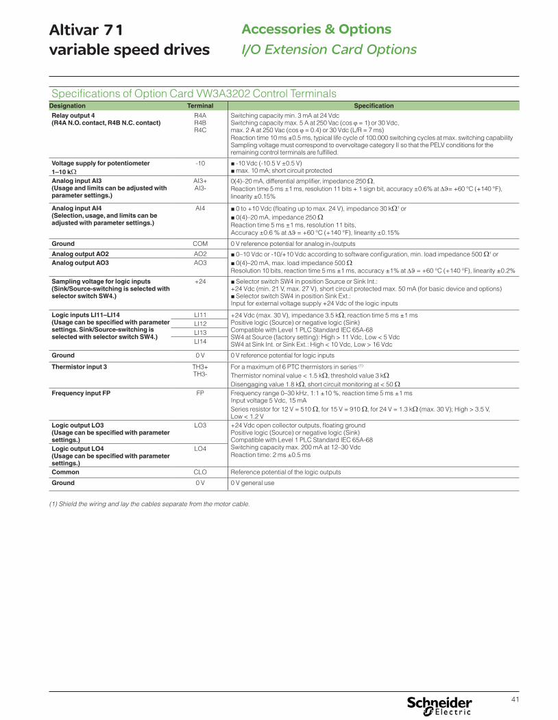
41
Altivar 71variable speed drives I/O Extension Card Options
Accessories & Options
Specifications of Option Card VW3A3202 Control TerminalsDesignation Terminal Specification
Relay output 4(R4A N.O. contact, R4B N.C. contact)
R4AR4BR4C
Switching capacity min. 3 mA at 24 VdcSwitching capacity max. 5 A at 250 Vac (cos � = 1) or 30 Vdc,max. 2 A at 250 Vac (cos � = 0.4) or 30 Vdc (L/R = 7 ms)Reaction time 10 ms ±0.5 ms, typical life cycle of 100.000 switching cycles at max. switching capabilitySampling voltage must correspond to overvoltage category II so that the PELV conditions for theremaining control terminals are fulfilled.
Voltage supply for potentiometer1–10 k�
-10 � -10 Vdc (-10.5 V ±0.5 V) �max. 10 mA; short circuit protected
Analog input AI3(Usage and limits can be adjusted withparameter settings.)
AI3+AI3-
0(4)–20 mA, differential amplifier, impedance 250 �,Reaction time 5 ms ±1 ms, resolution 11 bits + 1 sign bit, accuracy ±0.6% at ��= +60 °C (+140 °F),linearity ±0.15%
Analog input AI4(Selection, usage, and limits can beadjusted with parameter settings.)
AI4 � 0 to +10 Vdc (floating up to max. 24 V), impedance 30 k�1 or � 0(4)–20 mA, impedance 250 �
Reaction time 5 ms ±1 ms, resolution 11 bits,Accuracy ±0.6 % at �� = +60 °C (+140 °F), linearity ±0.15%
Ground COM 0 V reference potential for analog in-/outputs
Analog output AO2 AO2 � 0–10 Vdc or -10/+10 Vdc according to software configuration, min. load impedance 500 �1 or � 0(4)–20 mA, max. load impedance 500 �
Resolution 10 bits, reaction time 5 ms ±1 ms, accuracy ±1% at �� = +60 °C (+140 °F), linearity ±0.2%Analog output AO3 AO3
Sampling voltage for logic inputs(Sink/Source-switching is selected withselector switch SW4.)
+24 � Selector switch SW4 in position Source or Sink Int.:+24 Vdc (min. 21 V, max. 27 V), short circuit protected max. 50 mA (for basic device and options)
� Selector switch SW4 in position Sink Ext.:Input for external voltage supply +24 Vdc of the logic inputs
Logic inputs LI11–LI14(Usage can be specified with parametersettings. Sink/Source-switching isselected with selector switch SW4.)
LI11 +24 Vdc (max. 30 V), impedance 3.5 k�, reaction time 5 ms ±1 msPositive logic (Source) or negative logic (Sink)Compatible with Level 1 PLC Standard IEC 65A-68SW4 at Source (factory setting): High > 11 Vdc, Low < 5 VdcSW4 at Sink Int. or Sink Ext.: High < 10 Vdc, Low > 16 Vdc
LI12LI13LI14
Ground 0 V 0 V reference potential for logic inputs
Thermistor input 3 TH3+TH3-
For a maximum of 6 PTC thermistors in series (1)
Thermistor nominal value < 1.5 k�, threshold value 3 k�Disengaging value 1.8 k�, short circuit monitoring at < 50 �
Frequency input FP FP Frequency range 0–30 kHz, 1:1 ±10 %, reaction time 5 ms ±1 msInput voltage 5 Vdc, 15 mASeries resistor for 12 V = 510 �, for 15 V = 910 �, for 24 V = 1.3 k� (max. 30 V); High > 3.5 V, Low < 1.2 V
Logic output LO3(Usage can be specified with parametersettings.)
LO3 +24 Vdc open collector outputs, floating groundPositive logic (Source) or negative logic (Sink)Compatible with Level 1 PLC Standard IEC 65A-68Switching capacity max. 200 mA at 12–30 VdcReaction time: 2 ms ±0.5 ms
Logic output LO4(Usage can be specified with parametersettings.)
LO4
Common CLO Reference potential of the logic outputs
Ground 0 V 0 V general use
(1) Shield the wiring and lay the cables separate from the motor cable.

42
Altivar 71variable speed drives IMC Controller Card
Accessories & Options
Altivar IMC integrated controllerThe Altivar IMC integrated controller card forms a part of Flexible Machine Control approach, a key component of MachineStruxureTM, which brings you maximum flexibility and provides the most optimized control solution.
The Altivar IMC integrated controller card VW3A3521S0 is a compact optimized solution developed for Altivar 61 and 71 variable speed drives. When equipped with the ATV IMC card, Altivar 61 and 71 drives become controllers capable of meeting the needs of machine manufacturers (OEMs) in applications such as textiles, hoisting, pumping or woodworking, etc.
The Altivar IMC integrated controller card VW3A3521S0 is configured and programmed using SoMachine software.
The Altivar IMC card boosts the expansion capability of machines and allows us to meet the OEM market's requirements in terms of performance, simplicity of use and openness.
InstallationThe Altivar IMC card is designed for integration on Altivar 71 variable speed drives in conjunction with other Altivar 71-specific cards, such as I/O expansion cards and communication cards.
1 Altivar 71 drive and graphic display keypad2 Altivar IMC card VW3A3521S03 I/O expansion card VW3A32pp or communication card VW3A33pp
Note: Only one I/O expansion card or communication card can be mounted simultaneously with the Altivar IMC card on an Altivar 71 drive.
Altivar IMC integrated controller card
Special featuresUser memory RAM 2 MB
Flash 2 MB
Data storage memory FRAM (Ferroelectric RAM) 64 KB
Typical time (for 1000 Boolean instructions) 942 μs
User program size 1 MB
Power supply 24 V c
Inputs Digital 10 x 24 V c inputs, 4 of which can be used for 2 high-speed counter inputs (100 kHz) or 2 incremental encoders (A/B) (100 kHz)
Analog 2 x 0…20 mA inputs
Outputs Digital 6 transistor outputs (2 A) - source
Analog 2 x 0…20 mA outputs
Built-in communication ports RJ45 port Ethernet Modbus TCP, Web/FTP Server
SUB-D connector (male 9-way) Master CANopen bus (16 slaves)
USB Mini-B port SoMachine software programming
Real-time clock Integrated
1
1
2
3
Altivar IMC integrated controller cardDesignation Voltage Part number Weight
lbs kg
Altivar IMC integrated controller card 24 V c VW3A3521 0.4 0.2
Connection cableDesignation Use Length Part number Weight
ft m lbs kg
Programming cable From the mini USB-B port on the Altivar IMC integrated controller card to the type A USB port on the PC terminal for programming and updating firmware
9.8 3 TCSXCNAMUM3P 0.2 0.1
TCSXCNAMUM3P

43
Altivar 71variable speed drives IMC Controller Card
Accessories & Options
SoMachine software platform
PerformanceReduce the time it takes to develop your machines b The use of a single SoMachine programming software environment offers a number of advantages:
v A single project file v A single software program v A single download for the whole application
b The ease of use of PLCopen function blocks significantly reduces the time needed to program motion control and independent axis control on machines.
A more powerful machineThe Altivar IMC integrated controller card has 8 tasks to suit different machine requirements (cyclic, event-triggered, free). A task can be synchronized with the task of the drive in which it is embedded. This task manages the speed reference, the torque reference, the speed feedback, the torque feedback, the number of encoder pulses feedback in order to increase machine performance.
A more intelligent drive � Performs more complex operations (2 MB memory) � Reduces program loading time (Mini-B USB connectors) � Communication with all the other system devices (built-in Ethernet and CANopen connection ports)
Transparency of your machinesAccess to all the other devices in the system architecture via CANopen is totally transparent due to FDT/DTM technology.
Development and technologyThe Altivar IMC integrated controller card has been developed with two criteria in mind: low cost and practicality.
b Low cost because the standard equipment for the Altivar IMC card comprises: v Sixteen discrete I/O v A built-in Ethernet port v Two analog inputs v Two analog outputs v And a CANopen master
b Practicality because the Altivar IMC card is ideal for integration in Altivar 71 drives, and can therefore use: v Their inputs/outputs v Their communication cards v Their parameters: speed, current, torque, etc. v Their remote graphic display keypad v And also the inputs/outputs in their I/O expansion cards v Plus the speed feedback counter in the encoder interface cards
Software configurationConfiguration and programming of the Altivar IMC integrated controller card and equipment in Schneider Electric's “Flexible Machine Control” concept are both designed to cut costs and optimize your machine performance.Schneider Electric’s SoMachineTM software platform can be used to program Altivar IMC integrated controller card using:
b IEC 61131-3 programming languages: Instruction List (IL), Ladder Diagram (LD), Function Block Diagram (FBD), Sequential Function Chart/Grafcet (SFC) and Structured Text (ST)
b CFC (Continuous Function Chart) language.PLCopen function blocks are used for managing motion control and axis control on your machines.
Integration in the Schneider Electric product offerCombined with other OEM products in the Schneider Electric offer, such as Altivar variable speed drives, LexiumTM servo drives, MagelisTM HMI terminals, TeSysTM motor starters and contactors, the Altivar IMC integrated controller card can be integrated transparently in a number of architectures.

44
Altivar 71variable speed drives IMC Controller Card
Accessories & Options
Analog functions
High-speed counter function (one-phase or two-phase)
CANopen (1 Mbps)
up to 2 high-speed counters (100 kHz)
Altivar 71 + Altivar IMC integrated controller card
Machine with CANopen architecture:- Lifting motion: Altivar 71- Translatory motion: Altivar 312- Carriage motion: Altivar 312
FunctionsAnalog functions
For machines that require functions to process data issued by analog sensors/actuators (voltage or current), temperature sensors, pressure or PID control sensors, the Altivar IMC card has, as standard, 2 analog inputs (voltage or current) with 10-bit resolution and 2 analog outputs (current) with 10-bit resolution.
1 Altivar IMC integrated controller card installed on Altivar 612 Pressure sensor3 Variable speed pump4 Fixed speed pumps
HSC high-speed counting and/or incremental encoder functionIn order to meet requirements for machine productivity, the Altivar IMC has 2 embedded high-speed counters with a counting frequency of 100 kHz for each channel as well as 4 reflex outputs. The availability of these embedded counters and also the presence of the master CANopen link makes it quick and easy to create low-cost, high-performance multi-axis functions that suit the machines limitations. With the availability of “PLCopen” function blocks specific to the motion control functions in the SoMachine software, application development is sure to be quick and reliable. In addition, these high-speed counting inputs can be used as an incremental encoder (A/B) with a frequency of 100 kHz in order to adapt to the machine's specific requirements.
Position control functionSeveral options are offered in terms of position control:
b Either creating a sequence in Lexium 32 servo drives, with communication with the Altivar IMC integrated controller card achieved by the use of discrete I/O
b Or creating an application in the Altivar IMC card and controlling the Lexium 32A/ Lexium 32M servo drives and/or SD3pp stepper motor drives via the master CANopen integrated link.

45
Altivar 71variable speed drives IMC Controller Card
Accessories & Options
Functions (continued)Communication functionEthernet
The Altivar IMC integrated controller card has a built-in RJ45 Ethernet port (10/100 Mbps, MDI/MDIX) with Ethernet TCP Modbus, SoMachine on Ethernet, UDP, TCP and SNMP protocols. In addition, the Altivar IMC card has an embedded Web Server and FTP Server. As well as the default address based on the MAC address, it is possible to assign a controller IP address via a DHCP server or via a BOOTP server.
CANopenThe Altivar IMC integrated controller card has an embedded CANopen master which can be used to control devices on a communication bus with ease. The link can be configured between 20 kbps and 1 Mbps and supports up to 16 slaves. Architectures based on CANopen can be used to distribute I/O modules as close to the sensors and actuators as possible, thus reducing wiring costs and times, and to communicate with different devices such as variable speed drives, servo drives, etc. The CANopen configurator is integrated in the SoMachine software and can also be used to import standard description files in EDS format.
Customization function on the graphic display keypadMenu 1.14
The remote graphic display keypad on Altivar 71 drives includes a menu dedicated to the Altivar IMC integrated controller card. The user is offered a graphic display of 8 lines of 24 characters. This menu can be customized simply and directly using the SoMachine software. The user can define the language, name, unit, decimal point, and the type of parameter he wishes to customize for his own application. The user can also define alarms and error messages for his application.
Clock functionA time and date-stamping function combined with a clock backed up by a lithium battery makes it possible to keep a log of events that have occurred. When the Altivar IMC integrated controller card is installed in the drive, drive faults are automatically time and date-stamped without the need for any special programming.
Menu 1.14

46
Altivar 71variable speed drives IMC Controller Card
Accessories & Options
CommunicationThe Altivar IMC integrated controller card has the following built-in communication ports:
Communication ports Use
1 x RJ45 (MDI/MDIX port) v FTP server v Web server v Modbus TCP server v Modbus TCP client v Manager SoMachine v SNMP v Modbus device
1 x mini-USB Programming port (480 Mbps)
1 x 9-way male SUB-D Master CANopen connection
Embedded EthernetThe Altivar IMC integrated controller card has an embedded Ethernet link via a direct connection to its RJ45 port.
b Speed: “10 BaseT” and “100 BaseTX” with auto-negotiation b RJ45 port (MDI/MDIX): automatic adaptation to a straight or crossed cable
Protocols Number of connections
Modbus server 8
Modbus device 2
FTP server 4
Web server 10
DescriptionThe Altivar IMC integrated controller card comprises: 1 Three spring connectors for:
v 10 digital inputs v 6 digital outputs v 2 analog inputs v 2 analog outputs v 2 commons
2 A connector with removable screw terminals, 3 contacts at intervals of 3.81 for the 24 V c power supply
3 A mini USB-B connector for programming using SoMachine software4 A 9-way SUB-D connector for connection to the CANopen machine bus5 An RJ45 connector for connection of the SoMachine software workshop and/or
connection to an Ethernet Modbus TCP network6 Five LEDs:
v 1 green/yellow ETH LED for Ethernet activity v 1 green/red NS (Network status) LED v 1 green/red MS (Module status) LED v 1 green/red CAN (CANopen activity) LED v 1 green/red LED programmable by the user
7 Four configuration selector switches
2
34
5
17
6
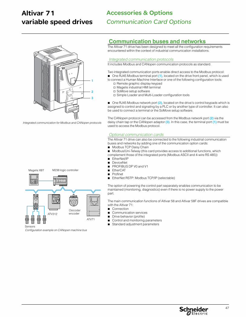
47
Altivar 71variable speed drives
Accessories & OptionsCommunication Card Options
Communication buses and networksThe Altivar 71 drive has been designed to meet all the configuration requirements encountered within the context of industrial communication installations.
Integrated communication protocolsIt includes Modbus and CANopen communication protocols as standard.
Two integrated communication ports enable direct access to the Modbus protocol: b One RJ45 Modbus terminal port (1), located on the drive front panel, which is used
to connect a Human Machine Interface or one of the following configuration tools: v Remote graphic display keypad v Magelis industrial HMI terminal v SoMove setup software v Simple Loader and Multi-Loader configuration tools
b One RJ45 Modbus network port (2), located on the drive's control keypads which is assigned to control and signaling by a PLC or by another type of controller. It can also be used to connect a terminal or the SoMove setup software.
The CANopen protocol can be accessed from the Modbus network port (2) via the daisy chain tap or the CANopen adaptor (3). In this case, the terminal port (1) must be used to access the Modbus protocol.
Optional communication cardsThe Altivar 71 drive can also be connected to the following industrial communication buses and networks by adding one of the communication option cards:
b Modbus TCP Daisy Chain b Modbus/Uni-Telway (this card provides access to additional functions, which
complement those of the integrated ports (Modbus ASCII and 4-wire RS 485)) b EtherNet/IP b DeviceNet b PROFIBUS DP V0 and V1 b EtherCAT b Profinet b EtherNet RSTP: Modbus TCP/IP (selectable)
The option of powering the control part separately enables communication to be maintained (monitoring, diagnostics) even if there is no power supply to the power part.
The main communication functions of Altivar 58 and Altivar 58F drives are compatible with the Altivar 71:
b Connection b Communication services b Drive behavior (profile) b Control and monitoring parameters b Standard adjustment parameters
1
2
3
Integrated communication for Modbus and CANopen protocols
Configuration example on CANopen machine busSensors
M238 logic controllerMagelis XBT
ATV312Osicoder encoder
ATV71

48
Altivar 71variable speed drives
Accessories & OptionsCommunication Card Options
FunctionsAll drive functions can be accessed via the network:
b Configuration b Adjustment b Control b Monitoring
The Altivar 71 drive's advanced functions provide excellent interfacing flexibility. They enable the different control sources (I/O, communication networks, communication cards and graphic display keypad) to be assigned to control functions that satisfy the requirements of numerous, complex applications. Network configuration is simplified through the provision of configuration software (configurator for SyCon® networks, etc.).
For the integrated Modbus and CANopen ports and the communication cards for industrial applications, the Altivar 71 drive can be controlled:
b According to the CiA 402 profile b According to the I/O profile, where control is as simple and adaptable as control
via the I/O terminals.
The DeviceNet card also supports CIP AC Drive and Allen-Bradley drive profiles; PROFIBUS DP V0 and V1 cards also support the PROFIdrive profile.
Communication is monitored according to the specific criteria for each protocol. However, regardless of the protocol, it is possible to configure how the drive responds to a communication fault:
b Freewheel stop, stop on ramp, fast stop or braked stop b Maintain the last command received b Fallback position at a predefined speed b Ignore the fault
A command from the CANopen machine bus is processed with the same priority as one of the drive terminal inputs. This results in excellent response times on the network port via the CANopen adaptor.

49
Altivar 71variable speed drives
Accessories & OptionsCommunication Card Options
1 1
22
CANopen machine busDescription Item
no.Length Part number Weight
ft m lbs kg
Connection via RJ45 connector (optimized solution for daisy chain connection to the CANopen machine bus)
CANopen cordsetsequipped with 2 RJ45 connectors
1 1 0.3 VW3CANCARR03 0.1 0.05
3.3 1 VW3CANCARR1 1.1 0.5
Daisy chain tapequipped with:
b 2 RJ45 connectors for connecting the CANopen bus in a daisy chain
b 1 cordset equipped with an RJ45 connector for connecting the drive
2 1 0.3 TCSCTN023F13M03 - –
Connection via SUB-D connectorCANopen adaptor for mounting on the RJ45 port on the drive control terminals.The adaptor provides a 9-way male SUB-D connector conforming to the CANopen standard (CIA DRP 303-1).
3 - – VW3CANA71 - –
CANopen connector (4) 9-way female SUB-D with line terminator (can be disabled).180° cable outlet for 2 CANopen cables.CAN-H, CAN-L, CAN-GND connection.
4 - – VW3CANKCDF180T - –
CANopen cables (1) (2) Standard cable, e marking Low smoke zero halogen Flame retardant (IEC 60332-1)
5 164 50 TSXCANCA50 10.8 4.9
328.1 100 TSXCANCA100 19.4 8.8
984.3 300 TSXCANCA300 54.2 24.6
CANopen cables (1) (2) UL certified, e marking Flame retardant (IEC 60332-2)
5 164 50 TSXCANCB50 7.9 3.6
328.1 100 TSXCANCB100 17.2 7.8
984.3 300 TSXCANCB300 48.3 21.9
CANopen cables (1) (2) Cable for harsh environments (5) or mobile installations, e marking Low smoke zero halogen Flame retardant (IEC 60332-1)
5 164 50 TSXCANCD50 7.7 3.5
328.1 100 TSXCANCD100 17.2 7.8
984.3 300 TSXCANCD300 47.8 21.7
Connection via terminalsDaisy chain tap equipped with:
b 2 spring terminal blocks for connecting the CANopen bus in a daisy chain
b 1 cordset equipped with an RJ45 connector for connecting the drive
6 2 0.6 TSCCTN026M16M - –
(1) Please refer to the “Modicon M238 Logic Controller” and “M258 Logic Controller” catalogues.(2) Cable dependent on the type of controller or PLC. (3) Please refer to the “Modicon M340 Automation Platform” catalogue.(4) For ATV71HpppM3, ATV71HD11M3X, HD15M3X, ATV71H075N4…HD18N4, ATV71H075N4383...HD18N4383 and ATV71HU22Y...HC63Y drives, this connector can be replaced by the TSXCANKCDF180T connector.(5) Harsh environments: - Resistance to hydrocarbons, industrial oils, detergents, solder splashes - Relative humidity up to 100% - Saline atmosphere - Significant temperature variations - Operating temperature between - 10°C and + 70°C.
5 5
6 6 6
ATV71
Modicon M238/Modicon M258 (1)
Example of CANopen diagram with daisy chain tap
CA
Nop
en m
achi
ne b
us
(2)
(2)
Optimized solution for daisy chain connection to the CANopen machine bus
Modicon M238/Modicon M258 (1)
ATV71
CA
Nop
en m
achi
ne b
us
(2)
34
5
Example of CANopen diagram with SUB-D connector
M340 PLC (3)
ATV71
CA
Nop
en m
achi
ne b
us

50
Altivar 71variable speed drives
Accessories & OptionsCommunication Card Options
Modbus serial link- Connection accessories metInoitpircseD
no.Length Part number Weight
gksblmtfModbus splitter box10 RJ45 connectors and 1 screw terminal
1 - – LU9GC3 1.1 0.5
Cables for Modbus serial link equipped with 2 RJ45 connectors
2 1 0.3 VW3A8306R03 0.07 0.03
3.3 1 VW3A8306R10 0.2 0.1
9.8 3 VW3A8306R30 0.2 0.1
Modbus T-junction boxes (with integrated cable)
3 1 0.3 VW3A8306TF03 0.4 0.2
3 1 VW3A8306TF10 0.4 0.2
Line terminatorsfor RJ45 connector (3)
R = 120 C = 1 nf
4 - – VW3A8306RC 0.02 0.01
R = 150 4 - – VW3A8306R 0.02 0.01
(1) Please refer to the “Modicon M340 Automation Platform” catalog.(2) Cable dependent on the type of controller or PLC.(3) Order in lots of 2.
Example of Modbus diagram with connection via splitter box and RJ45 connectors
422
(2)
21 23 3 4
3 3
M340 PLC (1)
ATV71
Mod
bus
ser
ial l
ink

51
Altivar 71variable speed drives
Accessories & OptionsCommunication Card Options
Modbus TCP Daisy Chain and EtherNet/IP network (1) (2)
Description Length Part number Weight
ft m lbs kg
Communication cardsModbus TCP Daisy Chain Equipped with 2 RJ45 connectors
Modbus TCP 10/100 Mbps class C20- - VW3A3310D 0.7 0.3
EtherNet/IP Equipped with 2 RJ45 connectors - - VW3A3316 0.7 0.3
ConneXium Modbus TCP (VW3A3310D) or EtherNet/IP (VW3A3316 and VW3A3320) cordsetsStraight shielded twisted pair cordsets
Equipped with 2 RJ45 connectorsTo be connected on a hub or on a switch
6.6 2 490NTW00002 - -
16.4 5 490NTW00005 - -
39.4 12 490NTW00012 - -
131.2 40 490NTW00040 - -
262.5 80 490NTW00080 - -
Modbus/Uni-Telway network (1) (2)
Description Length Part number Weight
ft m lbs kg
Communication cardModbus/Uni-Telway Equipped with a 9-way female SUB-D
connector- - VW3A3303 0.7 0.3
Connection accessories for Modbus/Uni-Telway card (VW3A3303)Subscriber socket Equipped with two 15-way female SUB-D
connectors and two screw terminal blocks. For 2-channel junction box, trunk cable extension and line terminator
- - TSXSCA62 1.3 0.6
Cordset for TSXSCA62 subscriber socket
Equipped with two 9-way and 15-way male SUB-D connectors
9.8 3 VW3A83062 0.4 0.2
(1) The Altivar 71 drive can only take one communication card. (2) User manuals can be downloaded from our website www.schneider-electric.com. For the PROFIBUS DP, DeviceNet cards, the description files in gsd, eds or xif format can also be downloaded from our website www.schneider-electric.com.(3) For a v5.7ie70#6 and above software version.
DeviceNet bus (1) (2)
Description Part number Weight
lbs kg
Communication card
DeviceNet Equipped with a 5-way removable screw terminal block VW3A3309 0.7 0.3
INTERBUS bus (1) (2)
Description Part number Weight
lbs kg
Communication cardINTERBUS Equipped with one 9-way male SUB-D connector and one 9-way
female SUB-D connectorTo be connected using cordset 170MCIppp00 (3)
VW3A3304 0.7 0.3
1
1
2
3

52
Altivar 71variable speed drives
Accessories & OptionsCommunication Card Options
PROFIBUS DP V0/V1 (1) (2)
Description Length Part number Weight
ft m lbs kg
Communication cardsPROFIBUS DP V0 Equipped with a 9-way female
SUB-D connector- – VW3A3307 0.7 0.3
PROFIBUS DP V1 Equipped with a 9-way female SUB-D connector
- – VW3A3307S371 0.7 0.3
Connection accessories for PROFIBUS DP V0 (VW3A3307) or V1 (VW3A3307S371) cardConnectors: 9-way male SUB-D
For middle of line - – 490NAD91104 - –
For end of line - – 490NAD91103 - –
Cable for connector 490NAD911pp
328.1 100 TSXPBSCA100 - –
1312.3 400 TSXPBSCA400 - –
(1) The Altivar 71 drive can only take one communication card. (2) User manuals can be downloaded from our website www.schneider-electric.com. For the PROFIBUS DP, DeviceNet cards, the description files in gsd, eds or xif format can also be downloaded from our website www.schneider-electric.com.

53
Altivar 71variable speed drives
Accessories & OptionsDynamic Braking Accessories
Dynamic braking resistorsDynamic braking (also referred to as resistance braking) allows the Altivar 71 to maintain control of the motor when the motor becomes an energy generator. Examples of a motor becoming a generator could be a hoist lowering a load, a downhill conveyor that is fully loaded, or a high inertia load requiring a fast deceleration time. The motor can become a generator when the load attached to the motor overhauls the motor. When the motor becomes a generator, the drive can be used to manage the energy being transferred from the load; through the motor back to the drive needs to be managed.
For applications where a significant amount of energy is being regenerated by the load, it may be prudent to consider an active front-end drive or engineer a system of Altivar 71 drives with a common DC bus tie. The active front-end is a second power section added between the Altivar 71 and the incoming power line and synchronizes the generated energy back to the incoming power line. A system of Altivar 71 drives with a common DC bus tie is common in applications where one load requires acceleration, while another is decelerating. Contact your Schneider Electric representative if you believe your application could benefit from an active front-end solution or DC bus tie solution.
For many applications where the motor becomes an energy generator, dynamic braking resistors can be used with the Altivar 71 to maintain control of the motor and manage speed and torque. The dynamic braking resistors are connected to the DC bus on the Altivar 71 through a transistor (also referred to as a chopper or dynamic braking transistor). When connected to a resistor, this transistor turns on before the energy coming back from the motor elevates the DC bus voltage to overvoltage trip level. The generated energy is then able to flow to the resistors and this energy is dissipated in the form of heat.
The following drives have a dynamic braking transistor built in: ATV71HpppM3,ATV71HpppM3X, ATV71H075N4…HC16N4, ATV71HpppS6X, and ATV71HU22Y…HC16Y.
An external braking transistor is required for ATV71HC20N4…HC50N4 and ATV71HC20Y…HC63Y. Powerohm Type BM Braking Modules monitor the DC bus voltage of the Altivar 71 and allow power to flow to the external braking resistors to avoid over-voltage trips and allow the Altivar 71 to provide braking torque. These braking modules are available in three voltage ranges. Powerohm Part
NumberRMC
Continuous Load Current
Turn ON Voltage
Max Peak Current
Dimensions
A B C D E
240 Nominal Line Voltage
ATVBM2-50 50 390 200 6.38 5.13 11 8.88 5.88
ATVBM2-115 115 390 200 6.38 5.13 12.75 8.88 5.88
ATVBM2-150 150 390 300 6.38 5.13 12.75 8.88 5.88
ATVBM240-450 450 390 600 7.13 10 20 5 19
ATVBM240-600 600 390 900 7.13 10 20 5 19
ATVBM240-900 900 390 1200 10.06 10 24 7 23
ATVBM240-1200 1200 390 1800 10.06 10 24 7 23
480 Nominal AC Line Voltage
ATVBM4-50 50 775 200 6.38 5.13 11 8.88 5.88
ATVBM4-115 115 775 200 6.38 5.13 12.75 8.88 5.88
ATVBM4-150 150 775 300 6.38 5.13 12.75 8.88 5.88
ATVBM480-450 450 775 600 7.13 10 20 5 19
ATVBM480-600 600 775 900 7.13 10 20 5 19
ATVBM480-900 900 775 1200 10.06 10 24 7 23
ATVBM480-1200 1200 775 1800 10.06 10 24 7 23
600 Nominal AC Line Voltage
ATVBM6-50 50 970 200 6.38 5.13 11 8.88 5.88
ATVBM6-115 115 970 200 6.38 5.13 12.75 8.88 5.88
ATVBM6-150 150 970 300 6.38 5.13 12.75 8.88 5.88
ATVBM600-450 450 970 600 7.13 10 20 5 19
ATVBM600-600 600 970 900 7.13 10 20 5 19
ATVBM600-900 900 970 1200 10.06 10 24 7 23
ATVBM600-1200 1200 970 1800 10.06 10 24 7 23
M1 3
L1
L2
L3
ATV71HpppM3ATV71HpppM3X
ATV71H075N4…HC16N4ATV71HpppS6X
ATV71HU22Y…HC16Y
Braking transistor
Braking resistor
M1 3
L1
L2
L3
Braking transistor
Braking resistor
ATV71HC20N4…HC50N4ATV71HC20Y…HC63Y

54
Altivar 71variable speed drives
Accessories & OptionsDynamic Braking Accessories
Drive Part Number HP kW Min Ohms
DC Bus Voltage
Required Braking Module
10% Decl 5% OHL
20% Decl 10% OHL
50% Decl 25% OHL
10% Decl 5% OHL
20% Decl 10% OHL
50% Decl 25% OHL
200-240 Voltage
ATV 71H037M3 0.5 0.37 44 390 N/A P184441 P184441 P184441 P184441 P184441 P184441
ATV 71H075M3 1 0.75 44 390 N/A P184441 P184441 P184441 P184441 P184441 P184441
ATV 71HU15M3 2 1.5 33 390 N/A P1844417 P1844417 P1844417 P1844417 P1844417 P1844418
ATV 71HU22M3 3 2.2 22 390 N/A P1844427 P1844427 P1844428 P1844427 P1844427 P1844429
ATV 71HU30M3 4 3 22 390 N/A P1844427 P1844427 P1844428 P1844427 P1844428 P1844429
ATV 71HU40M3 5 4 16 390 N/A P1844437 P1844437 P1844439 P1844437 P1844438 P1844442
ATV 71HU55M3 7.5 5.5 11 390 N/A P1844437 P1844438 P1844442 P1844438 P1844439 P1844447
ATV 71HU75M3 10 7.5 8 390 N/A P1844459 P1844460 P1844468 P1844460 P1844462 P1844463
ATV 71HD11M3X 15 11 3 390 N/A P1844482 P1844485 P1844487 P1844482 P1844483 P1844488
ATV 71HD15M3X 20 15 3 390 N/A P1844482 P1844489 P1844488 P1844485 P1844484 P1844491
ATV 71HD18M3X 25 18.5 4 390 N/A P1844498 P1844497 P1844499 P18444100 P18444101 P18444102
ATV 71HD22M3X 30 22 3.3 390 N/A P18444112 P18444111 P18444116 P18444110 P18444114 P18444118
ATV 71HD30M3X 40 30 3.3 390 N/A P18444110 P18444113 P18444118 P18444111 P18444115 P18444120
ATV 71HD37M3X 50 34 1.7 390 N/A P18444138 P18444141 P18444145 P18444140 P18444143 P18444146
ATV 71HD45M3X 60 45 1.7 390 N/A P18444139 P18444142 P18444147 P18444141 P18444143 P18444148
ATV 71HD55M3X 75 55 1.7 390 N/A P18444140 P18444143 P18444146 P18444142 P18444144 P18444149
ATV 71HD75M3X 100 75 1.3 390 N/A P18444150 P18444153 P18444156 P18444151 P18444154 P18444158
380-480 Voltage
ATV 71H075N4 1 0.75 56 750 N/A P184441 P184441 P184441 P184441 P184441 P184441
ATV 71HU15N4 2 1.5 56 750 N/A P184441 P184441 P184441 P184441 P184441 P184442
ATV 71HU22N4 3 2.2 56 750 N/A P184441 P184441 P184442 P184441 P184441 P184443
ATV 71HU30N4 4 3 34 750 N/A P184441 P184441 P184442 P184441 P184442 P184443
ATV 71HU40N4 5 4 34 750 N/A P1844417 P1844417 P1844419 P1844417 P1844418 P1844420
ATV 71HU55N4 7.5 5.5 23 750 N/A P1844417 P1844418 P1844420 P1844418 P1844419 P1844422
ATV 71HU75N4 10 7.5 19 750 N/A P1844417 P1844418 P1844421 P1844418 P1844419 P1844423
ATV 71HD11N4 15 11 12 750 N/A P1844428 P1844429 P1844435 P1844429 P1844432 P1844431
ATV 71HD15N4 20 15 7 750 N/A P1844460 P1844466 P1844464 P1844462 P1844461 P1844465
ATV 71HD18N4 25 18.5 7 750 N/A P1844462 P1844468 P1844465 P1844462 P1844463 P1844467
ATV 71HD22N4 30 22 13.3 750 N/A P1844449 P1844457 P1844453 P1844454 P1844450 P1844456
ATV 71HD30N4 40 30 13.3 750 N/A P1844452 P1844450 P1844455 P1844457 P1844451 P1844458
ATV 71HD37N4 50 37 6.7 750 N/A P1844472 P1844474 P1844477 P1844473 P1844475 P1844479
ATV 71HD45N4 60 45 5 750 N/A P1844484 P1844490 P1844494 P1844488 P1844492 P1844495
ATV 71HD55N4 75 55 5 750 N/A P1844487 P1844491 P1844495 P1844488 P1844493 P1844496
ATV 71HD75N4 100 75 3.3 750 N/A P18444115 P18444118 P18444121 P18444116 P18444120 P18444124
ATV 71HD90N4 125 90 2.5 750 N/A P18444115 P18444119 P18444123 P18444117 P18444122 P18444124
ATV 71HC11N4 150 110 1.9 750 N/A P18444125 P18444127 P18444133 P18444126 P18444129 P18444134
ATV 71HC13N4 200 130 1.9 750 N/A P18444126 P18444130 P18444133 P18444127 P18444132 P18444135
ATV 71HC16N4 250 160 1.9 750 N/A P18444126 P18444129 P18444134 P18444128 P18444133 P18444137
ATV 71HC20N4 300 200 1.05 750 ATVBM480450 P18444152 P18444156 P18444161 P18444155 P18444158 P18444163
ATV 71HC25N4 400 250 1.05 750 ATVBM480450 P18444154 P18444157 P18444162 P18444156 P18444159 P18444163
ATV 71HC28N4 450 280 1.05 750 ATVBM480450 P18444154 P18444158 P18444163 P18444157 P18444160 P18444164
ATV 71HC31N4 500 310 0.7 750 ATVBM480900 P18444173 P18444176 - P18444174 P18444177 -
ATV 71HC40N4 600 400 0.7 750 ATVBM480900 P18444174 P18444177 - P18444175 P18444178 -
ATV 71HC50N4 700 500 0.7 750 ATVBM480900 P18444175 P18444178 - P18444177 - -

55
Altivar 71variable speed drives
Accessories & OptionsDynamic Braking Accessories
Drive Part Number
HP kW Min Ohms
DC Bus Voltage
Required Braking Module
10% Decl 5% OHL
20% Decl 10% OHL
50% Decl 25% OHL
10% Decl 5% OHL
20% Decl 10% OHL
50% Decl 25% OHL
575-600 Voltage
ATV 71HU22Y, ATV71HU15S6X
2 1.5 12 970 N/A P184441 P184441 P184441 P184441 P184441 P184442
ATV 71HU30Y, ATV71HU22S6X
3 2.2 12 970 N/A P184441 P184441 P184442 P184441 P184441 P184443
ATV 71HU40Y, ATV71HU30S6X
4 3 12 970 N/A P184441 P184441 P184442 P184441 P184442 P184443
ATV 71HU55Y, ATV71HU40S6X
5 4 12 970 N/A P184441 P184441 P184443 P184441 P184442 P184444
ATV 71HU75Y, ATV71HU55S6X
7.5 5.5 12 970 N/A P184441 P184442 P184444 P184442 P184443 P184445
ATV 71HD11Y, ATV71HU75S6X
10 7.5 12 970 N/A P1844417 P1844418 P1844421 P1844418 P1844419 P1844423
ATV 71HD15Y 15 15 12 970 N/A P1844418 P1844419 P1844423 P1844419 P1844421 P1844425
ATV 71HD18Y 20 18.5 12 970 N/A P1844418 P1844420 P1844424 P1844419 P1844422 P1844426
ATV 71HD22Y 25 22 12 970 N/A P1844429 P1844432 P1844431 P1844430 P1844435 P1844433
ATV 71HD30Y 30 30 12 970 N/A P1844439 P1844447 P1844444 P1844445 P1844440 P1844446
ATV 71HD37Y 40 37 12 970 N/A P1844442 P1844440 P1844446 P1844447 P1844443 P1844448
ATV 71HD45Y 50 45 8 970 N/A P1844468 P1844464 P1844469 P1844463 P1844465 P1844471
ATV 71HD55Y 60 55 8 970 N/A P1844461 P1844465 P1844470 P1844463 P1844467 P1844471
ATV 71HD75Y 75 75 5 970 N/A P1844473 P1844475 P1844479 P1844474 P1844476 P1844480
ATV 71HD90Y 100 90 5 970 N/A P1844474 P1844476 P1844480 P1844475 P1844478 P1844481
ATV 71HC11Y 125 110 4 970 N/A P1844499 P18444103 P18444106 P18444102 P18444105 P18444107
ATV 71HC13Y 150 132 4 970 N/A P18444101 P18444104 P18444108 P18444103 P18444105 P18444109
ATV 71HC16Y 175 160 4 970 N/A P18444102 P18444105 P18444107 P18444103 P18444106 P18444109
ATV 71HC20Y 200 200 2 970 ATVBM600450 P18444126 P18444129 P18444134 P18444127 P18444132 P18444137
ATV 71HC25Y 250 250 2 970 ATVBM600450 P18444127 P18444131 P18444134 P18444129 P18444133 P18444137
ATV 71HC31Y 350 315 2 970 ATVBM600450 P18444128 P18444133 P18444137 P18444132 P18444134 P18444136
ATV 71HC40Y 450 400 1 970 ATVBM600600 P18444165 P18444168 P18444172 P18444167 P18444170 -
ATV 71HC50Y 550 500 1 970 ATVBM600600 P18444166 P18444169 P18444172 P18444168 P18444171 -
ATV 71HC63Y 700 630 1 970 ATVBM600600 P18444167 P18444170 - P18444169 P18444172 -

56
Altivar 71variable speed drives
Accessories & OptionsDynamic Braking Accessories
Part Number Ohms Watts Dimension Weight
inches lbs
P184441 100 400 12 x 5 x 5 7
P184442 100 800 12 x 7 x 5 9
P184443 100 1200 12 x 10 x 5 13
P184444 100 1600 12 x 13 x 5 16
P184445 100 2400 19 x 10 x 5 20
P1844417 40 400 12 x 5 x 5 7
P1844418 40 800 12 x 7 x 5 9
P1844419 40 1200 12 x 10 x 5 13
P1844420 40 1600 12 x 13 x 5 16
P1844421 40 2000 12 x 16 x 5 18
P1844422 40 2400 19 x 10 x 5 20
P1844423 40 2800 19 x 13 x 5 24
P1844424 40 4000 19 x 16 x 5 30
P1844425 40 4400 26.5 x 13 x 5 32
P1844426 40 5600 26.5 x 16 x 5 38
P1844427 25 400 12 x 5 x 5 7
P1844428 25 800 12 x 7 x 5 9
P1844429 25 1200 12 x 10 x 5 13
P1844430 25 1600 12 x 13 x 5 16
P1844431 25 5625 26.5 x 13 x 5 28
P1844432 25 2000 12 x 16 x 5 18
P1844433 25 8100 26.5 x 16 x 5 36
P1844435 25 2800 19 x 13 x 5 24
P1844437 16 400 12 x 5 x 5 7
P1844438 16 800 12 x 7 x 5 9
P1844439 16 1200 12 x 10 x 5 13
P1844440 16 3600 19 x 10 x 5 19
P1844442 16 1600 12 x 13 x 5 16
P1844443 16 5184 26.5 x 13 x 5 28
P1844444 16 6400 26.5 x 13 x 5 31
P1844445 16 2000 12 x 16 x 5 18
P1844446 16 8464 26.5 x 16 x 5 36
P1844447 16 2400 19 x 10 x 5 20
P1844448 16 10816 28 x 10 x 10 39
P1844449 14 1200 12 x 10 x 5 13
P1844450 14 3150 19 x 10 x 5 19
P1844451 14 4536 26.5 x 10 x 5 25
P1844452 14 1600 12 x 13 x 5 16
P1844453 14 5600 26.5 x 13 x 5 28
P1844454 14 2000 12 x 16 x 5 18
P1844455 14 7406 26.5 x 16 x 5 33
P1844456 14 9464 28 x 10 x 10 37
P1844457 14 2400 19 x 10 x 5 20
P1844458 14 11774 28 x 13 x 10 51
P1844459 10 400 12 x 5 x 5 7
P1844460 10 800 12 x 7 x 5 9
P1844461 10 2250 19 x 10 x 5 17
P1844462 10 1200 12 x 10 x 5 13
P1844463 10 3240 19 x 10 x 5 19
P1844464 10 4000 26.5 x 10 x 5 24
P1844465 10 5290 26.5 x 10 x 5 25
P1844466 10 1600 12 x 13 x 5 16
P1844467 10 6760 26.5 x 13 x 5 28
P1844468 10 2000 12 x 16 x 5 18
P1844469 10 10240 28 x 10 x 10 44
P1844470 10 12960 28 x 13 x 10 55
P1844471 10 16000 28 x 16 x 10 70
Part Number Ohms Watts Dimension Weight
inches lbs
P1844472 8 1800 19 x 10 x 5 16
P1844473 8 3200 19 x 10 x 5 19
P1844474 8 4232 28 x 10 x 10 32
P1844475 8 5408 28 x 10 x 10 32
P1844476 8 8192 26.5 x 16 x 5 37
P1844477 8 10368 28 x 10 x 10 44
P1844478 8 12800 28 x 13 x 10 59
P1844479 8 16200 28 x 16 x 10 70
P1844480 8 20000 30 x 18 x 16 99
P1844481 8 28800 30 x 18 x 24 142
P1844482 6 800 12 x 7 x 5 9
P1844483 6 1944 19 x 10 x 5 17
P1844484 6 2400 19 x 10 x 5 17
P1844485 6 1200 12 x 10 x 5 13
P1844487 6 3174 19 x 10 x 5 19
P1844488 6 4056 26.5 x 10 x 5 24
P1844489 6 1600 12 x 13 x 5 16
P1844490 6 5046 26.5 x 13 x 5 30
P1844491 6 6144 26.5 x 13 x 5 32
P1844492 6 7776 26.5 x 16 x 5 37
P1844493 6 9600 28 x 10 x 10 47
P1844494 6 12150 28 x 13 x 10 57
P1844495 6 15000 28 x 13 x 10 67
P1844496 6 21600 28 x 16 x 10 89
P1844497 4.5 1800 19 x 10 x 5 16
P1844498 4.5 1200 12 x 10 x 5 13
P1844499 4.5 4608 26.5 x 10 x 5 26
P18444100 4.5 1600 12 x 13 x 5 16
P18444101 4.5 5832 26.5 x 13 x 5 32
P18444102 4.5 7200 26.5 x 16 x 5 39
P18444103 4.5 9112 26.5 x 16 x 5 41
P18444104 4.5 11250 28 x 10 x 10 53
P18444105 4.5 16200 28 x 13 x 10 74
P18444106 4.5 22050 28 x 16 x 10 99
P18444107 4.5 32512 30 x 18 x 16 151
P18444108 4.5 28800 30 x 18 x 16 105
P18444109 4.5 45000 30 x 18 x 24 204
P18444110 3.3 1745 19 x 10 x 5 16
P18444111 3.3 2230 19 x 10 x 5 17
P18444112 3.3 1200 12 x 10 x 5 13
P18444113 3.3 2775 19 x 10 x 5 19
P18444114 3.3 3379 19 x 10 x 5 21
P18444115 3.3 4276 26.5 x 10 x 5 26
P18444116 3.3 5280 26.5 x 13 x 5 33
P18444117 3.3 6682 26.5 x 13 x 5 34
P18444118 3.3 8250 26.5 x 6 x 5 44
P18444119 3.3 8923 28 x 10 x 10 40
P18444120 3.3 11880 28 x 10 x 10 58
P18444121 3.3 16170 28 x 13 x 10 75
P18444122 3.3 13516 28 x 13 x 10 55
P18444123 3.3 23842 30 x 18 x 16 127
P18444124 3.3 33000 30 x 18 x 24 176
P18444125 2.2 5500 26.5 x 10 x 5 30
P18444126 2.2 7920 26.5 x 13 x 5 41
P18444127 2.2 10780 26.5 x 16 x 5 54
P18444128 2.2 11404 28 x 13 x 10 56
P18444129 2.2 15895 28 x 13 x 10 82
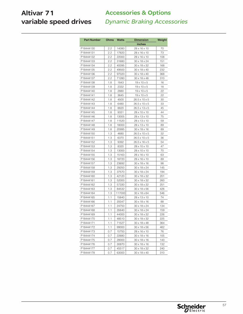
57
Altivar 71variable speed drives
Accessories & OptionsDynamic Braking Accessories
Part Number Ohms Watts Dimension Weight
inches
P18444130 2.2 14080 28 x 16 x 10 70
P18444131 2.2 17820 28 x 16 x 10 73
P18444132 2.2 22000 28 x 16 x 10 108
P18444133 2.2 31680 30 x 18 x 24 151
P18444134 2.2 40095 30 x 18 x 32 168
P18444135 2.2 49500 30 x 18 x 40 232
P18444136 2.2 97020 30 x 18 x 40 368
P18444137 2.2 71280 30 x 18 x 48 310
P18444138 1.8 1843 19 x 10 x 5 16
P18444139 1.8 2332 19 x 10 x 5 18
P18444140 1.8 2880 19 x 10 x 5 22
P18444141 1.8 3645 19 x 10 x 5 22
P18444142 1.8 4500 26.5 x 10 x 5 30
P18444143 1.8 6480 26.5 x 10 x 5 33
P18444144 1.8 8820 26.5 x 13 x 5 45
P18444145 1.8 9331 28 x 10 x 10 44
P18444146 1.8 13005 28 x 13 x 10 75
P18444147 1.8 11520 28 x 13 x 10 59
P18444148 1.8 18000 28 x 13 x 10 89
P18444149 1.8 20995 30 x 18 x 16 89
P18444150 1.3 4680 26.5 x 10 x 5 32
P18444151 1.3 6370 26.5 x 10 x 5 36
P18444152 1.3 9392 26.5 x 16 x 5 54
P18444153 1.3 8320 28 x 10 x 10 47
P18444154 1.3 13000 28 x 10 x 10 70
P18444155 1.3 15163 28 x 16 x 10 63
P18444156 1.3 18720 28 x 16 x 10 89
P18444157 1.3 23692 30 x 18 x 16 98
P18444158 1.3 29250 30 x 18 x 24 145
P18444159 1.3 37570 30 x 18 x 24 194
P18444160 1.3 42120 30 x 18 x 32 201
P18444161 1.3 52000 30 x 18 x 32 260
P18444162 1.3 57330 30 x 18 x 32 251
P18444163 1.3 84532 30 x 18 x 56 426
P18444164 1.3 117000 30 x 18 x 64 546
P18444165 1.1 15840 28 x 13 x 10 74
P18444166 1.1 20047 30 x 18 x 16 88
P18444167 1.1 24750 30 x 18 x 24 134
P18444168 1.1 35640 30 x 18 x 24 159
P18444169 1.1 44000 30 x 18 x 32 226
P18444170 1.1 48510 30 x 18 x 32 225
P18444171 1.1 71527 30 x 18 x 48 364
P18444172 1.1 99000 30 x 18 x 56 462
P18444173 0.7 15750 28 x 16 x 10 76
P18444174 0.7 22680 30 x 18 x 16 105
P18444175 0.7 28000 30 x 18 x 16 143
P18444176 0.7 30870 30 x 18 x 16 132
P18444177 0.7 45517 30 x 18 x 32 240
P18444178 0.7 63000 30 x 18 x 40 310

58
Altivar 71variable speed drives
Input Power OptionsLine Reactors
Line reactors Line reactors (also referred to as line chokes) are used to provide improved protection against overvoltages on the line supply to reduce input currents to the drive and to reduce harmonic distortion of the current produced by the drive. Line reactors (or some form of additional impedance) are recommended when the impedance of the power distribution system is low, such as when the power of the system transformer is ten times larger than the power rating of the drive.
Line reactors are mandatory: b For ATV71HC11Y…HC63Y drives
They can also be used with: b ATV71HpppM3 drives powered by a 200...240 V 50/60 Hz three-phase supply and
with ATV71HpppM3X, ATV71ppppN4 and ATV71PppppN4Z drives b ATV71pppY variable speed drives in order to reach a total rate of distortion in
current in conformity with the IEC 61000-3-12 standard
Note: ATV71HD90N4...HC50N4, supplied as standard with a DC choke, can be ordered without a choke by adding the letter D at the end of the reference.
s s adsf
Chokes must be installed upstream of the drive.
ApplicationsThe use of line chokes is recommended in particular under the following circumstances:��Close connection of several drives in parallel��Line supply with significant disturbance from other equipment (interference, overvoltages)��Line supply with voltage imbalance between phases that is more than 1.8% of the nominal voltage��Drive supplied by a line with very low impedance (in the vicinity of power transformers 10 times more powerful than the drive rating)��Installation of a large number of frequency inverters on the same line��Reduction of overloads on the cos � correction capacitors, if the installation includes a power factor correction unit
M1 3 Altivar 71
L1
L2
L3Line choke

59
Altivar 71variable speed drives Line Reactors
Input Power Options
For drives Quan-tity
required per
drive
Part number Weight Line sup-ply Isc
Line choke UL recognized CSA certified
Part number (1)
WeightInduc-tance value
Nomi-nal
current
Satura-tion
current
Loss
lbs kg kA mH A A W lbs kg
Single-phase supply voltage: 200…240 V 50/60 HzATV71HU40M3X 1 - - - - - - - - RL02502 14 6.3
ATV71HU55M3X 1 - - - - - - - - RL03502 16 7.3
ATV71HU75M3X 1 - - - - - - - - RL05502 27 12
ATV71HD15M3X 1 - - - - - - - - RL08002 51 23
ATV71HD22M3X 1 - - - - - - - - RL10002 51 23
ATV71HD30M3X 1 - - - - - - - - RL13002 57 26
ATV71HD37M3X 1 - - - - - - - - RL16002 50 23
ATV71HD45M3X 1 - - - - - - - - RL20003B14 100 45
Three-phase supply voltage: 200…240 V 50/60 HzATV71H037M3 1 VW3A4551 3.3 1.5 5 10 4 - 45 RL00401 4 1.8
ATV71H075M3 1 VW3A4551 3.3 1.5 5 10 4 - 45 RL00401 4 1.8
ATV71HU15M3 1 VW3A4552 6.6 3 5 4 10 - 65 RL00801 7 3.2
ATV71HU22M3 1 VW3A4552 6.6 3 5 4 10 - 65 RL01201 9 4.1
ATV71HU30M3 1 VW3A4553 7.7 3.5 5 2 17 - 75 RL01801 9 4.1
ATV71HU40M3 1 VW3A4554 13.2 6 5 1 31 - 90 RL01801 9 4.1
ATV71HU55M3 1 VW3A4554 13.2 6 22 1 31 - 90 RL02501 11 5
ATV71HU75M3 1 VW3A4555 24.3 11 22 0.5 60 - 94 RL03501 14 6.3
ATV71HD11M3X 1 VW3A4555 24.3 11 22 0.5 60 - 94 RL04501 23 10
ATV71HD15M3X 1 - - - - - - - - RL05501 24 11
ATV71HD18M3X 1 - - - - - - - - RL08001 43 20
ATV71HD22M3X 1 - - - - - - - - RL10001 47 21
ATV71HD30M3X 1 - - - - - - - - RL13001 50 23
ATV71HD37M3X 1 - - - - - - - - RL16001 57 26
ATV71HD45M3X 1 - - - - - - - - RL20001 67 30
ATV71HD55M3X 1 - - - - - - - - RL25001 68 31
ATV71HD75M3X 1 - - - - - - - - RL32001 110 50
Three-phase supply voltage: 380…480 V 50/60 HzATV71H075N4 1 VW3A4551 3.3 1.5 5 10 4 - 45 RL00201 4 1.8
ATV71HU15N4 1 VW3A4551 3.3 1.5 5 10 4 - 45 RL00402 5 2.3
ATV71HU22N4 1 VW3A4552 6.6 3 5 4 10 - 65 RL00402 5 2.3
ATV71HU40N4 1 VW3A4552 6.6 3 5 4 10 - 65 RL00802 11 5
ATV71HU55N4 1 VW3A4553 7.7 3.5 22 2 17 - 75 RL01202 18 8.2
ATV71HU75N4 1 VW3A4553 7.7 3.5 22 2 17 - 75 RL01802 16 7.3
ATV71HD11N4 1 VW3A4554 13.2 6 22 1 31 - 90 RL02502 20 9.1
ATV71HD15N4 1 VW3A4554 13.2 6 22 1 31 - 90 RL03502 30 14
ATV71HD18N4 1 VW3A4555 24.3 11 22 0.5 60 - 94 RL03502 30 14
ATV71HD22N4 1 VW3A4555 24.3 11 22 0.5 60 - 94 RL04502 39 18
ATV71HD30N4 1 - - - - - - - - RL05502 41 19
ATV71HD37N4 1 - - - - - - - - RL08002 61 28
ATV71HD45N4 1 - - - - - - - - RL08002 61 28
ATV71HD55N4 1 - - - - - - - - RL10002 74 34
ATV71HD75N4 1 - - - - - - - - RL13002 64 29
ATV71HD90N4 1 - - - - - - - - RL16002 67 30
ATV71HC11N4 1 - - - - - - - - RL20002 100 45
ATV71HC13N4 1 - - - - - - - - RL25002 140 63
ATV71HC16N4 1 - - - - - - - - RL32002 190 86
ATV71HC20N4 1 - - - - - - - - RL40002 200 91
ATV71HC25N4 1 - - - - - - - - RL50002 290 132
ATV71HC28N4 1 - - - - - - - - RL60002 290 132
ATV71HC31N4 1 - - - - - - - - RL60002 290 132
ATV71HC40N4 2 - - - - - - - - RL40002B14 155 70
ATV71HC50N4 2 - - - - - - - - RL50002 180 82
(1) See Short Circuit Current Ratings on pages 23-28 for more information about UL recognized line reactors.
VW3A4572

60
Altivar 71variable speed drives Line Reactors
Input Power Options
For drives Quan-tity re-
quired per
drive
Part number Weight Line supply
Isc
Line choke UL recognized
CSA certified part
number(2)
WeightInduc-tance value
Nominal current
Satura-tion
current
Loss
lbs kg kA mH A A W lbs kg
Three-phase supply voltage: 500…600 V 50/60 HzATV71HU15S6X 1 VW3A4551 3.3 1.5 22 10 4 – 45 RL00403 5 2.3
ATV71HU22S6X 1 VW3A4551 3.3 1.5 22 10 4 – 45 RL00403 5 2.3
ATV71HU30S6X 1 VW3A4551 3.3 1.5 22 10 4 – 45 RL00403 11 5
ATV71HU40SX6 1 VW3A4552 6.6 3 22 4 10 – 65 RL00803 11 5
ATV71HU55S6X 1 VW3A4552 6.6 3 22 4 10 – 65 RL01203 18 8.2
ATV71HU75S6X 1 VW3A4553 7.7 3.5 22 2 17 – 75 RL01203 18 8.2
Three-phase supply voltage: 500…690 V 50/60 HzATV71HU22Y 1 VW3A4551 3.3 1.5 22 10 4 - 45 RL00403 5 2.3
ATV71HU30Y 1 VW3A4551 3.3 1.5 22 10 4 - 45 RL00403 5 2.3
ATV71HU40Y 2 VW3A4552 6.6 3 22 4 10 - 65 RL00803 11 5
ATV71HU55Y 2 VW3A4552 6.6 3 22 4 10 - 65 RL00803 11 5
ATV71HU75Y 2 VW3A4552 6.6 3 22 4 10 - 65 RL00802 8 3.6
ATV71HD11Y 1 VW3A4553 7.7 3.5 22 2 17 - 75 RL01202 10 4.5
ATV71HD15Y 1 VW3A4553 7.7 3.5 22 2 17 - 75 RL01802 14 6.3
ATV71HD18Y 1 VW3A4554 13.2 6 22 1 31 - 90 RL02502 14 6.3
ATV71HD22Y 1 VW3A4554 13.2 6 22 1 31 - 90 RL02502 20 9.1
ATV71HD30Y 1 VW3A4555 24.3 11 22 0.5 60 - 94 RL03502 16 7.3
ATV71HD37Y 1 VW3A4555 24.3 11 22 0.5 60 - 94 RL04502 26 11.8
ATV71HD45Y 1 VW3A4555 24.3 11 22 0.5 60 - 94 RL05502 27 12
ATV71HD55Y 1 VW3A4556 35.3 16 22 0.3 107 - 260 RL08002 51 23
ATV71HD75Y 1 - - - - - - - - RL08002 51 23
ATV71HD90Y 1 - - - - - - - - RL10002 51 23
ATV71HC11Y (1) 1 - - - - - - - - RL13002 57 26
ATV71HC13Y (1) 1 - - - - - - - - RL16002 50 23
ATV71HC16Y (1) 1 - - - - - - - - RL20002 67 30
ATV71HC20Y (1) 1 - - - - - - - - RL20002 67 30
ATV71HC25Y (1) 1 - - - - - - - - RL25002 106 48
ATV71HC31Y (1) 1 - - - - - - - - RL40002 155 70
ATV71HC40Y (1) 2 - - - - - - - - RL25002B14 106 48
ATV71HC50Y (1) 2 - - - - - - - - RL32002B14 125 57
ATV71HC63Y (1) 2 - - - - - - - - RL40002B14 155 70
(1) Use of a line choke is mandatory.(2) See Short Circuit Current Ratings on pages 23-28 for more information about UL recognized line
reactors.

61
Altivar 71variable speed drives
Input Power OptionsPassive filters
Passive filtersPassive filters are used to reduce current harmonics with total harmonic distortion factors of less than 16% or 10%.
These performance levels can be improved still further and the harmonic distortion reduced to less than 10% or 5% if the filter is used with a DC choke.
The reactive power increases at no load or low load. To eliminate this reactive power, the filter capacitors can be disconnected via the drive (refer to the Programming Manual).
The passive filters provide IP 20 protection.
ATV71HpppY and ATV71HpppS6X drives are not compatible with the use of passive filters. It is recommended or mandatory, depending on the rating, to use a line choke.
ApplicationsReduction of current harmonics in order to use drives in the first environment (restricted distribution, for domestic use, sale conditional on the competence of the user and the distributor in terms of reduction of current harmonics).
ATV71ppppN4ATV71WpppN4C
L1
L2
L3
Passive filter
Motor rating For ATV 71 drives Line Supply
Filter Filter Quan-tity per Drive
Part Number (2) Packaging Size Weight
Line Current
Input Current
Output Current
L x L x H Net
kw HP A A A inches cm lbs kg
THDI 16% (1)
0.75 1 ATV 71H075N4 2.5 6 6.2 1 VW3A46139 23.6 x 15.7 x 20.1 60 x 40 x 51 22 10
1.5 2 ATV 71HU15N4 3 6 6.2 1 VW3A46139 23.6 x 15.7 x 20.1 60 x 40 x 51 22 10
2.2 3 ATV 71HU22N4 5 6 6.2 1 VW3A46139 23.6 x 15.7 x 20.1 60 x 40 x 51 22 10
3 - ATV 71HU30N4 6 6 6.2 1 VW3A46139 23.6 x 15.7 x 20.1 60 x 40 x 51 22 10
4 5 ATV 71HU40N4 7 10 10.4 1 VW3A46140 23.6 x 15.7 x 20.1 60 x 40 x 51 29.8 13.5
5.5 7.5 ATV 71HU55N4 10 10 10.4 1 VW3A46140 23.6 x 15.7 x 20.1 60 x 40 x 51 29.8 13.5
7.5 10 ATV 71HU75N4 13 14 14.5 1 VW3A46141 23.6 x 15.7 x 20.1 60 x 40 x 51 35.9 16.3
11 15 ATV 71HD11N4 19 19 19.5 1 VW3A46142 23.6 x 15.7 x 20.1 60 x 40 x 51 48.5 22
15 20 ATV 71HD15N4 24 25 26 1 VW3A46143 23.6 x 15.7 x 20.1 60 x 40 x 51 50.7 23
18 25 ATV 71HD18N4 32 31 32 1 VW3A46144 31.5 x 23.6 x 24 80 x 60 x 61 72.8 33
22 30 ATV 71HD22N4 35 36 37.5 1 VW3A46145 31.5 x 23.6 x 24 80 x 60 x 61 81.6 37
30 40 ATV 71HD30N4 44 48 50 1 VW3A46146 31.5 x 23.6 x 24 80 x 60 x 61 83.8 38
37 50 ATV 71HD37N4 58.7 60 62.5 1 VW3A46147 31.5 x 23.6 x 24 80 x 60 x 61 94.8 43
45 60 ATV 71HD45N4 68 73 76 1 VW3A46148 31.5 x 23.6 x 24 80 x 60 x 61 121.3 55
55 75 ATV 71HD55N4 82.6 95 99 1 VW3A46149 31.5 x 23.6 x 24 80 x 60 x 61 136.7 62
75 100 ATV 71HD75N4 108 118 122.5 1 VW3A46150 31.5 x 23.6 x 24 80 x 60 x 61 163.1 74
(1) Adding a DC choke can reduce THDI to <5%.(2) Filters are rated for 460V 60Hz three phase power supply.

62
Altivar 71variable speed drives Passive filters
Input Power Options
Motor rating For ATV 71 drives Line Supply
Filter Filter Quan-tity per Drive
Part Number (1) Packaging Size Weight
Line Current
Input Current
Output Current
L x L x H Net
kw HP A A A inches cm lbs kg
THDI 10%
0.75 1 ATV 71H075N4 2.5 6 6.2 1 VW3A46158 23.6 x 15.7 x 20.1 60 x 40 x 51 39.7 18
1.5 2 ATV 71HU15N4 3 6 6.2 1 VW3A46158 23.6 x 15.7 x 20.1 60 x 40 x 51 39.7 18
2.2 3 ATV 71HU22N4 4.2 6 6.2 1 VW3A46158 23.6 x 15.7 x 20.1 60 x 40 x 51 39.7 18
3 - ATV 71HU30N4 6 6 6.2 1 VW3A46158 23.6 x 15.7 x 20.1 60 x 40 x 51 39.7 18
4 5 ATV 71HU40N4 7 10 10.4 1 VW3A46159 23.6 x 15.7 x 20.1 60 x 40 x 51 39.7 18
5.5 7.5 ATV 71HU55N4 10 10 10.4 1 VW3A46159 23.6 x 15.7 x 20.1 60 x 40 x 51 39.7 18
7.5 10 ATV 71HU75N4 13 14 14.5 1 VW3A46160 23.6 x 15.7 x 20.1 60 x 40 x 51 44.1 20
11 15 ATV 71HD11N4 19 19 19.5 1 VW3A46161 23.6 x 15.7 x 20.1 60 x 40 x 51 66.1 30
15 20 ATV 71HD15N4 24 25 26 1 VW3A46162 23.6 x 15.7 x 20.1 60 x 40 x 51 75 34
18 25 ATV 71HD18N4 32 31 32 1 VW3A46163 31.5 x 23.6 x 24 80 x 60 x 61 114.6 52
22 30 ATV 71HD22N4 35 36 37.5 1 VW3A46164 31.5 x 23.6 x 24 80 x 60 x 61 116.8 53
30 40 ATV 71HD30N4 44 48 50 1 VW3A46165 31.5 x 23.6 x 24 80 x 60 x 61 125.7 57
37 50 ATV 71HD37N4 58.7 60 62.5 1 VW3A46166 31.5 x 23.6 x 24 80 x 60 x 61 165.3 75
45 60 ATV 71HD45N4 68 73 76 1 VW3A46167 31.5 x 23.6 x 24 80 x 60 x 61 213.8 97
55 75 ATV 71HD55N4 82.6 95 99 1 VW3A46168 31.5 x 23.6 x 24 80 x 60 x 61 229.3 104
75 100 ATV 71HD75N4 108 118 122.5 1 VW3A46169 31.5 x 23.6 x 24 80 x 60 x 61 233.7 106
THDI 10%
90 125 ATV 71HD90N4 134 154 160 1 VW3A46151 31.5 x 23.6 x 24 80x60x61 187.4 85
110 150 ATV 71HC11N4 163 183 190 1 VW3A46152 31.5 x 23.6 x 24 80x60x61 224.9 102
132 200 ATV 71HC13N4 192 231 240 1 VW3A46153 47.2 x 31.5 x 28.3 120x80x72 257.9 117
160 250 ATV 71HC16N4 235 231 240 1 VW3A46153 47.2 x 31.5 x 28.3 120x80x72 257.9 117
200 300 ATV 71HC20N4 300 355 369 1 VW3A46155 47.2 x 31.5 x 28.3 120x80x72 357.1 162
220 350 ATV 71HC25N4 330 355 369 1 VW3A46155 47.2 x 31.5 x 28.3 120x80x72 357.1 162
250 400 ATV 71HC25N4 400 436 450 1 VW3A46157 47.2 x 31.5 x 28.3 120x80x72 451.9 205
280 450 ATV 71HC28N4 440 436 450 1 VW3A46157 47.2 x 31.5 x 28.3 120x80x72 451.9 205
315 500 ATV 71HC31N4 470 231 240 2 VW3A46153 47.2 x 31.5 x 28.3 120x80x72 257.9 117
355 - ATV 71HC40N4 530 291 316 2 VW3A46154 47.2 x 31.5 x 28.3 120x80x72 313.1 142
400 600 ATV 71HC40N4 590 291 316 2 VW3A46154 47.2 x 31.5 x 28.3 120x80x72 313.1 142
500 700 ATV 71HC50N4 730 380 395 2 VW3A46156 47.2 x 31.5 x 28.3 120x80x72 379.2 172
THDI 5%
90 125 ATV 71HD90N4 134 154 160 1 VW3A46170 31.5 x 23.6 x 24 80x60x61 277.8 126
110 150 ATV 71HC11N4 163 183 190 1 VW3A46171 31.5 x 23.6 x 24 80x60x61 297.6 135
132 200 ATV 71HC13N4 192 231 240 1 VW3A46172 47.2 x 31.5 x 28.3 120x80x72 374.8 170
160 250 ATV 71HC16N4 235 231 240 1 VW3A46172 47.2 x 31.5 x 28.3 120x80x72 374.8 170
200 300 ATV 71HC20N4 300 355 369 1 VW3A46174 47.2 x 31.5 x 28.3 120x80x72 504.9 229
220 350 ATV 71HC25N4 330 355 369 1 VW3A46174 47.2 x 31.5 x 28.3 120x80x72 504.9 229
250 400 ATV 71HC25N4 400 436 450 1 VW3A46176 47.2 x 31.5 x 28.3 120x80x72 595.2 270
280 450 ATV 71HC28N4 440 436 450 1 VW3A46176 47.2 x 31.5 x 28.3 120x80x72 595.2 270
315 500 ATV 71HC31N4 470 231 240 2 VW3A46172 47.2 x 31.5 x 28.3 120x80x72 374.8 170
355 - ATV 71HC40N4 530 291 316 2 VW3A46173 47.2 x 31.5 x 28.3 120x80x72 454.2 206
400 600 ATV 71HC40N4 590 291 316 2 VW3A46173 47.2 x 31.5 x 28.3 120x80x72 504.9 229
500 700 ATV 71HC50N4 730 380 395 2 VW3A46175 47.2 x 31.5 x 28.3 120x80x72 584.2 265
(1) Filters are rated for 460V 60Hz three phase power supply.

63
Altivar 71variable speed drives EMC filters
Input Power Options
Integrated EMC filtersAltivar 71 drives (excluding the ATV71HpppM3X) have built-in radio interference filters to comply with the EMC standard for adjustable speed electrical power drive systems IEC/EN 61800-3, edition 2, category C2 or C3 in environment 1 or 2 and the European Electromagnetic Compatibility Directive. Drives Maximum length of shielded cable (1) according to
EN 55011 class A Gr1
EN 55011 class A Gr2
IEC/EN 61800-3 category C2
IEC/EN 61800-3 category C3
LF HF LF HF
ft m ft m ft m ft m
ATV71H037M3…HU22M3 32.8 10 16.4 5 - - - -
ATV71HU30M3…HU75M3 32.8 10 16.4 5
ATV71H075N4…HU40N4 32.8 10 16.4 5 - - - -
ATV71HU55N4…HD15N4 - - - - 32.8 10 16.4 5
ATV71HD18N4…HC50N4 - - - - 164 50 82 25
ATV71HU22Y…HD90Y - - - - 82 25 82 25
ATV71HC11Y…HC63Y - - - - 164 50 82 25
Switching frequencyDrives Switching frequency
LF (low frequency) HF (high frequency)
kHz kHz
ATV71HpppM3ATV71H075N4…HD30N4
4 4.1…16
ATV71HD37N4…HD75N4 2…2.5 2.6…12
ATV71HD90N4…HC50N4 2…4 4.1…8
ATV71HU22Y…HD30Y 2.5…4 4.1…6
ATV71HD37Y…HC63Y 2.5 2.6…4.9
Additional EMC input filtersApplications
When used with ATV71HpppM3, ATV71HpppM3X, and ATV71ppppN4, additional EMC input filters can be used to meet more stringent requirements and are designed to reduce conducted emissions on the line supply below the limits of standards EN 55011 group 1, class A or B and IEC/EN 61800/3 category C2 or C3.
For ATV71HpppM3, ATV71HD11M3X…HD45M3X, and ATV71H075N4…HD75N4, additional EMC filters can be mounted beside or under the drive. They act as a support for the drives and are attached to them via tapped holes.For ATV71HD55M3X, HD75M3X, and ATV71HD90N4…HC50N4, additional EMC filters can only be mounted beside the drive.
Use according to the line supply typeUse of these additional filters is only possible on TN (connected to neutral) and TT (neutral to ground) type networks. Standard IEC/EN 61800-3, appendix D2.1, states that on IT networks (isolated or impedance grounded neutral), filters can cause permanent insulation monitors to operate in a random manner.
In addition, the effectiveness of additional filters on this type of network depends on the type of impedance between neutral and ground, and therefore cannot be predicted.
In the case of a machine which needs to be installed on an IT network, the solution would be to insert an isolation transformer and place the machine locally on a TN or TT network.
(1) If motors are connected in parallel, it is the sum of all cable lengths that should be taken into account.
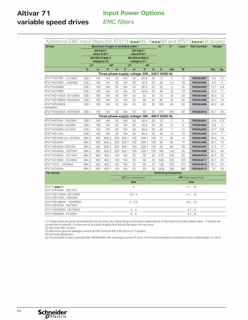
64
Altivar 71variable speed drives EMC filters
Input Power Options
Additional EMC input filters (for ATV71HpppM3, HpppM3 and ATV71ppppN4 drives)Drives Maximum length of shielded cable (1) In (2) If (3) Loss (4) Part number Weight
EN 55011 class A Gr1
EN 55011 class B Gr1
IEC/EN 61800-3 category C2
IEC/EN 61800-3 category C1
LF HF LF HFft m ft m ft m ft m A mA W lbs kg
Three-phase supply voltage: 200…240 V 50/60 HzATV71H037M3…HU15M3 328.1 100 164 50 164 50 65.6 20 12 4 10 VW3A4401 4.9 2.2
ATV71HU22M3…HU40M3 328.1 100 164 50 164 50 65.6 20 26 4.4 18 VW3A4402 8.8 4
ATV71HU55M3 328.1 100 164 50 164 50 65.6 20 35 3 24 VW3A4403 12.7 5.8
ATV71HU75M3 328.1 100 164 50 164 50 65.6 20 46 10 19 VW3A4404 15.4 7
ATV71HD11M3X, HD15M3X 328.1 100 164 50 164 50 82 25 72 33 34 VW3A4405 26.5 12
ATV71HD18M3X, HD22M3X 328.1 100 164 50 164 50 82 25 90 33 34 VW3A4406 33.1 15
ATV71HD30M3X...HD45M3X
328.1 100 164 50 164 50 82 25 180 80 58 VW3A4408 88.2 40
ATV71HD55M3X, HD75M3X 328.1 100 164 50 164 50 82 25 273 285 60 VW3A4410 55.1 25
Three-phase supply voltage: 380…480 V 50/60 HzATV71H075N4…HU22N4 328.1 100 164 50 164 50 65.6 20 12 7 5 VW3A4401 4.9 2.2
ATV71HU30N4, HU40N4 328.1 100 164 50 164 50 65.6 20 26 8 6 VW3A4402 8.8 4
ATV71HU55N4, HU75N4 328.1 100 164 50 164 50 65.6 20 35 7 14 VW3A4403 12.7 5.8
ATV71HD11N4 328.1 100 164 50 164 50 65.6 20 46 14 13 VW3A4404 15.4 7
ATV71HD15N4 (5), HD18N4 984.3 300 656.2 200 328.1 100 328.1 100 72 60 14 VW3A4405 26.5 12
ATV71HD22N4 984.3 300 656.2 200 328.1 100 328.1 100 90 60 11 VW3A4406 33.1 15
ATV71HD30N4, HD37N4 984.3 300 656.2 200 328.1 100 328.1 100 92 60 30 VW3A4407 37.5 17
ATV71HD45N4…HD75N4 984.3 300 656.2 200 328.1 100 328.1 100 180 140 58 VW3A4408 88.2 40
ATV71HD90N4…HC13N4 984.3 300 492.1 150 164 50 82 25 273 500 60 VW3A4410 48.5 22
ATV71HC16N4…HC28N4 984.3 300 492.1 150 164 50 82 25 546 500 125 VW3A4411 55.1 25
ATV71HC31...HC40N4 984.3 300 492.1 150 164 50 82 25 728 500 210 VW3A4412 55.1 25
ATV71HC50N4 984.3 300 492.1 150 164 50 82 25 1456 200 380 VW3A4413 75 34For drives Switching frequency
LF (low frequency) HF (high frequency)
kHz kHz
ATV71HpppM3 ATV71H075N4…HD11N4
4 4.1…16
ATV71HD11M3X, HD15M3X ATV71HD15N4…HD30N4
3.5...4 4.1…12
ATV71HD18M3X...HD45M3XATV71HD37N4...HD75N4
2…2.5 2.6…12
ATV71HD55M3X, HD75M3X 2…4 4.1…8
ATV71HD90N4...HC50N4 2…4 4.1…8
(1) These limits are given as examples only as they vary depending on the stray capacitance of the motors and the cables used. If motors are connected in parallel, it is the sum of all cable lengths that should be taken into account.(2) Nominal filter current.(3) Maximum ground leakage current at 230 V and at 400 V 50 Hz on a TT system.(4) Via heat dissipation.(5) It is possible to use a special filter VW3A4409 with a leakage current If (3) of 14 mA which enables a maximum motor cable length of 100 m.

65
Altivar 71variable speed drives
Output Power OptionsdV/dt output filters
dV/dt output filtersIn applications where the impedance on either end of the motor cable run does not match, voltage pulses may be reflected back. As these reflected waves encounter other waves, their values add, causing high peak voltages. Voltage wave reflection and peak voltages increase with longer cable lengths, increased drive switching frequency, and faster voltage rise times, (dV/dt).
When installed, dV/dt filters increase the time it takes the voltage to rise, slowing the pulse transitions, reducing dV/dt, reducing voltage peaks, and protecting motor and cable insulation.
For drives Nominal current
UL Recog-nized Part Number
Weight
A lbs kg
Three-phase supply voltage: 380�480 V 50/60 HzATV71H075N4 3 V1K3A00 8 4
ATV71HU15N4 4 V1K4A00 8 4
ATV71HU22N4 6 V1K6A00 8 4
ATV71HU30N4 8 V1K8A00 8 4
ATV71HU40N4 12 V1K12A00 8 4
ATV71HU55N4 16 V1K16A00 12 5
ATV71HU75N4 18 V1K18A00 12 5
ATV71HD11N4 27 V1K27A00 12 5
ATV71HD15N4 35 V1K35A00 12 5
ATV71HD18N4 45 V1K45A00 17 8
ATV71HD22N4 55 V1K55A00 16 7
ATV71HD30N4 80 V1K80A00 23 10
ATV71HD37N4 80 V1K80A00 23 10
ATV71HD45N4 110 V1K110A00 40 18
ATV71HD55N4 130 V1K130A00 55 25
ATV71HD75N4 160 V1K160A00 60 27
ATV71HD90N4 200 V1K200A00 60 27
ATV71HC11N4 250 V1K250A00 65 29
ATV71HC13N4 305 V1K305A00 80 36
ATV71HC16N4 362 V1K362A00 80 36
ATV71HC20N4 420 V1K420A00 95 43
ATV71HC25N4 480 V1K480A00 100 45
ATV71HC28N4 600 V1K600A00 130 59
ATV71HC31N4 750 V1K750A00 135 61

66
Altivar 71variable speed drives Introduction
M-Flex
IntroductionSchneider Electric has offered packaged drive solutions for industry for over 30 years. The M-Flex™ enclosed drive features the Altivar 71 adjustable frequency power converters to provide a robust, packaged adjustable-speed solution for industrial and municipal process applications where high functionality of features are required. M-Flex enclosed drive controllers offer a platform of standard, engineered and special features to meet the most demanding application and specification requirements. M-Flex enclosed drive controllers are low-voltage products available in the following ratings:
Constant torque (Heavy-duty ratings - 150% current limit): Altivar 71 power converter 1 hp to 450 hp, 460 V 1 hp to 40 hp, 208 V/230 V
M-Flex enclosed drive controllers are available in Type 1 general purpose or Type 12/12K drip-/dust-proof enclosures in integrated or barriered designs. Integrated enclosures can be wall or floor mounted, depending on size. They provide a circuit breaker disconnect and enough room for power peripherals, including isolation and bypass contactors, all within the same enclosure. Barriered enclosures separate power and control circuits, such as bypass, from drive control. The separate compartments allow for maximum flexibility if servicing a drive in bypass operation.
Applications The M-Flex enclosed offer is well suited to applications requiring a heavy duty enclosed drive in the following market segments:
MMM b Belt conveyors b Slurry pumps b Tension equipment b Puller car b Positive displacement pumps b Winches
Oil and Gas b Pumping b Compressors b Booster stations
WWW b Agitators b Blowers b Centrifuges b Positive displacement pumps
OTHER INDUSTRIAL b Chippers b Mills b Mixers b Presses b Winders
The Altivar 71 drive's advanced functions boost performance levels and make machines more versatile so they can be used for a large number of applications.
Barriered construction
Integrated construction
Oil and Gas
MMM
WWW

67
Altivar 71variable speed drives
ProductKey benefits
b Custom performance – customized to provide optimal performance to meetspecific industrial, municipal and high-end commercial application requirements.
b Ease of use – features easy-to-use graphic terminal display and operators mounted on enclosure doors, which are pre-programmed by the factory to save set-up time and money when commissioning.
b Simple installation – available with either pre-punched conduit knockouts or topand bottom removable conduit plates to save time and prevent metal filings insideenclosure during installation.
b Structural integrity – UL 508C listed to exceed minimum UL short circuitrequirements and enhance personnel safety under short circuit conditions for both drive and bypass mode.
b Increased functionality – offered with both integral and barriered enclosures forflexibility in meeting specific application needs. A circuit breaker disconnect providescoordinated short circuit rating at 100,000 A.
b Reliable operation – fully-rated (AC3 duty) motor isolation and bypass contactors with electrical and mechanical and electrical interlocks prevent accidental voltagefeedback. An integrated AC line reactor provides transient protection from surgeand over voltage conditions while minimizing line harmonics.
Seismic qualification for new generation of building codesAll M-Flex enclosed drive controllers meet IBC and ASCE 7 seismic qualification requirements in accordance with the ICC ES AC156 shaker table testing protocol. Many states and jurisdictions are beginning enforcement of the seismic guidelines for installed equipment contained in the IBC. The M-Flex enclosed drive controllerswere subjected to actual shaker table tests, not just theoretical calculations for seismic ratings or obsolete requirements of the UBC. The M-Flex enclosed drive controller meets the structural integrity when installed to our published guidelines, and can be specified for use in applications that require an Ip = 1.5, which meansoperational status can be restored subsequent to a seismic event.
Construction methodology b Assembled in the U.S. b 100,000 A symmetrical SCCR b ANSI #49 powder-coat steel enclosures b Dedicated plenum for air flow b White back panels for improved visibility b Seismic qualification
Components used b Altivar 61 and 71 drives b PowerpactTM H and J-Frame circuit breakers b AC line reactor – 3% standard (5% optional) b XB5 22 mm push buttons and operators b TeSys™ D-Line contactors b Type R industrial control relays b PowerLogicTM power circuit monitors
Introduction M-Flex
3% AC line reactor
Customer interface terminal blocks (TB1)
Circuit breaker disconnect
120 VAC control transformer
3-15 PSI input (if used)
22 mm dedicated door mounted operators
Heatsink/flange assembly
Altivar 61 or 71 power converter
Control relay/logic rail
Customer interface terminal blocks (TB2)
Fan assembly with front access (for maintenance and replacement)
Line contactor (if used)
Isolation and bypass contactors (if used)
Document pocket
1
5
12
3
1110
9
8
76
4
2
13
14
1
2
3
4
5
6
7
8
9
10
11
12
13
14

68
Altivar 71variable speed drives
Input voltage 460 V ±10%, 230 V ±10%, 208 V ±10%
Displacement power factor 98% through speed range
Input frequency 60 Hz ±5%
Output voltage Three-phase outputMaximum voltage equal to input voltage
Galvanic isolation Galvanic isolation between power and control (input, output, and power supplies)
Frequency range of power converter 0.1 Hz to 500 Hz (factory setting of 60 Hz)
Torque/overtorque VT: 110% of nominal motor torque for 60 sCT: 150% of nominal motor torque for 60 s
Current (transient) VT: 110% of controller rated current for 60 sCT: 150% of controller rated current for 60 s
Switching frequency Selectable from 0.5 kHz to 16 kHz (1) Factory setting:VT: 8 kHz for 208 V, 203 V, and 1 hp to 100 hp @ 460 V2 kHz for 125 hp to 500 hp @ 460 VCT: 4 kHz (2 kHz for 100 hp to 450 hp @ 460 V)The drive reduces the switching frequency automatically in the event of excessive heatsink temperature
Speed reference Al1: 0 V to +10 V, Impedance = 30 k�. Can be used for speed potentiometer, 1k� to 10 k�Al2: Factory setting: 4 mA to 20 mA. Impedance = 242 � (reassignable, x-y range with graphic display keypad). Factory modification J10 allows 0 Vdc to 10 Vdc reference signal to Al2, Z = 30 k�
Frequency resolution in analog reference 0.1 for 100 Hz (11 bits)
Speed regulation V/f control: equal to the motor’s rated slipSFVC: 10% of the motor’s rate slip from 20% to 100% of nominal motor torque
Efficiency 97% at full load typical
Reference sample time 2 ms ±0.5 ms
Acceleration and deceleration ramps 0.1 s to 999.9 s (definition in 0.1 s increments)
Drive controller protection � Thermal protection of power converter � Phase loss of AC mains � Circuit breaker rated at 100 kAIC � Conforming to ANSI/IEEE C62.41 Category A and B
Motor protection Class 10 electronic overload protectionClass 20 electromechanical overload protection with bypass (2)
Graphic display keypad 8 lines, 240 pixels by 160 pixels. Supports display of bar charts. Save and download up to 4 configuration files. Display is rated up to 60˚ C (140˚ F) Maximum operating temperature with IP54 protection
Temperature Storage for all enclosures: -13˚ F to +149˚ F (-25˚ C to +65˚ C). Operation: +14˚ F to +104˚ F (-10˚ C to 40˚ C). For 1 hp to 100 hp drives (208 V, 230 V & 460 V) operating between 40˚ C and 50˚ C, derate the current 2% per ˚C above 40˚ C. For 125 hp to 500 hp (460 V) operating between 40˚ C and 50˚ C, derate the current 3.3% per ˚C above 40˚ C
Humidity 95% with no condensation or dripping water, conforming to IEC60068-2-78
Altitude 3,300 ft (1000 m) maximum without deratingDerating of the current by 1% for each additional 330 ft (100 m)
Enclosure Type 1: all controllersType 1G: 125 hp to 500 hp VT or 100 hp to 450 hp CT @ 460 V onlyType 12/12K: all except 125 hp to 500 hp VT and 100 hp to 450 hp CT @ 460 V
Pollution degree Type 1, 1G: Pollution degree 2 per NEMA ICS-1 Annex A and IEC 60664-1Type 12/12K: Pollution degree 3 per NEMA ICS-1 and IEC 60664-1
Operational test vibration Conforming to IEC 60721-3-3-3M3 amplitude1.5 mm peak to peak from 3 Hz to 13 Hz1 g from 13 Hz to 200 Hz
Transit test to shock Conforming to National Safe Transit Association and International Safe Transit Associationtest for packages
Operational shock 15 g, 11 ms
Seismic qualification IBC, ASCE 7ICC ES AC 156 shaker table acceptance protocol, ground and roof top applications with an importance factor of 1.5
Codes and standards UL listed per UL 508C under category NMMS (Power Conversion Equipment)Conforms to applicable NEMA ICS, NFPA, and IEC standardsManufactured under ISO 9001 standardsFactory modification G10 provides Canadian cUL certification
(1) On 1 hp to 75 hp CT and 1 hp to 100 hp VT controllers, above 4 kHz CT/8 kHz VT, select the next largest size drive controller. If the duty cycle does not exceed 60% (36 s maximum for a 60 s cycle), this is not necessary.(2) Class 10 electromechanical for 1 hp @ 460 V.
Specifications M-Flex

69
Altivar 71variable speed drives Selection table
M-Flex
M-FlexHP
Refer-ence Code
HP Ratings
Control-ler
Output Current
Enclo-sure
Frame Size
Power Circuits
Constant Torque - Heavy Duty Rating (150% current Limit)
Power Circuit W
Power Circuit Y
Power Circuit S
Power Circuit Z
Power Circuit T
Power Circuit R
208V, 60 HzC 1 4.6 A C Cp2CW Cp2CY - Cp2CZ Cp2CT -
D 2 7.5 A Dp2CW Dp2CY - Dp2CZ Dp2CT -
E 3 10.6 A Ep2CW Ep2CY - Ep2CZ Ep2CT -
F 5 16.7 A Fp2CW Fp2CY - Fp2CZ Fp2CT -
G 7.5 24.2 A D Gp2CW Gp2CY - Gp2CZ Gp2CT -
H 10 30.8 A Hp2CW Hp2CY - Hp2CZ Hp2CT -
J 15 46.2 A E Jp2CW Jp2CY - Jp2CZ Jp2CT -
K 20 59.4 A Kp2CW Kp2CY - Kp2CZ Kp2CT -
L 25 74.8 A Lp2CW Lp2CY - Lp2CZ Lp2CT -
M 30 88 A F Mp2CW Mp2CY - Mp2CZ Mp2CT -
N 40 114 A Np2CW Np2CY - Np2CZ Np2CT -
230 V, 60 Hz
C 1 4.6 A C Cp3CW Cp3CY - Cp3CZ Cp3CT -
D 2 7.5 A Dp3CW Dp3CY - Dp3CZ Dp3CT -
E 3 10.6 A Ep3CW Ep3CY - Ep3CZ Ep3CT -
F 5 16.7 A Fp3CW Fp3CY - Fp3CZ Fp3CT -
G 7.5 24.2 A D Gp3CW Gp3CY - Gp3CZ Gp3CT -
H 10 30.8 A Hp3CW Hp3CY - Hp3CZ Hp3CT -
J 15 46.2 A E Jp3CW Jp3CY - Jp3CZ Jp3CT -
K 20 59.4 A Kp3CW Kp3CY - Kp3CZ Kp3CT -
L 25 74.8 A Lp3CW Lp3CY - Lp3CZ Lp3CT -
M 30 88 A F Mp3CW Mp3CY - Mp3CZ Mp3CT -
N 40 114 A Np3CW Np3CY - Np3CZ Np3CT -
460 V, 60 HzC 1 2.1 A C Cp4CW Cp4CY - Cp4CZ Cp4CT -
D 2 3.4 A Dp4CW Dp4CY - Dp4CZ Dp4CT -
E 3 4.8 A Ep4CW Ep4CY - Ep4CZ Ep4CT -
F 5 7.6 A Fp4CW Fp4CY - Fp4CZ Fp4CT -
G 7.5 11 A Gp4CW Gp4CY - Gp4CZ Gp4CT -
H 10 14 A Hp4CW Hp4CY - Hp4CZ Hp4CT -
J 15 21 A Jp4CW Jp4CY - Jp4CZ Jp4CT -
K 20 27 A Kp4CW Kp4CY - Kp4CZ Kp4CT -
L 25 34 A Lp4CW Lp4CY - Lp4CZ Lp4CT -
M 30 40 A E Mp4CW Mp4CY - Mp4CZ Mp4CT -
N 40 52 A Np4CW Np4CY Np4CS Np4CZ Np4CT Np4CR
P 50 65 A Pp4CW Pp4CY Pp4CS Pp4CZ Pp4CT Pp4CR
Q 60 77 A F Qp4CW Qp4CY Qp4CS Qp4CZ Qp4CT Qp4CR
R 75 96 A Rp4CW Rp4CY Rp4CS Rp4CZ Rp4CT Rp4CR
S 100 124 A Sp4CW Sp4CY Sp4CS Sp4CZ Sp4CT Sp4CR
T 125 156 A H Tp4CW Tp4CY Tp4CS Tp4CZ Tp4CT Tp4CR
U 150 180 A I Up4CW Up4CY Up4CS Up4CZ Up4CT Up4CR
W 200 240 A Wp4CW Wp4CY Wp4CS Wp4CZ Wp4CT Wp4CR
X 250 302 A Xp4CW - Xp4CS Xp4CZ Xp4CT Xp4CR
Y 300 361 A J Yp4CW - Yp4CS Yp4CZ Yp4CT Yp4CR
Z 350 414 A Zp4CW - Zp4CS Zp4CZ Zp4CT Zp4CR
4 400 477 A 4p4CW - 4p4CS 4p4CZ 4p4CT 4p4CR
5 450 515 A 5p4CW - 5p4CS 5p4CZ 5p4CT 5p4CR
ClassCombination device8839 = Circuit breaker disconnect
TypeDesignMFD = M-Flex™ controller
Horsepower ratingC = 1 L = 25 U = 150D = 2 M = 30 W = 200E = 3 N = 40 X = 250F = 5 P = 50 Y = 300G = 7.5 Q = 60 Z = 350H = 10 R = 75 4 = 400J = 15 S = 100 5 = 450K = 20 T = 125 6 = 500
Enclosure environmental ratingG = Type 1 general purposeA = Type 12/12K dust/drip proofB = Type 1 with gasket/fan filterReplace p with desired enclosure rating
Voltage code2 = 208 V, 60 Hz3 = 230 V/240 V, 60 Hz4 = 460 V/480 V, 60 Hz
Application typeC = Constant torque (150% current limit)
Power circuit typeR = Barriered bypass – RVATS = Barriered bypass – soft startT = Isolation & transferW = Combination device (drive only)Y = Integrated bypass (IEC)Z = Barriered bypass – full voltage
ModsModifications(120+ options are available)A07 = Hand-Off-Auto selector switch with manual speed potentiometerH10 = Seismic qualifiedE301 = ANSI #61 enclosure paintSPL = Special features (specified)
SeriesSeries designationA = Altivar® 61/71 power converter platform
1
2
3
4
5
6
7
8
9
8839 MFD N G 4 V W A07 A1 2 3 4 5 6 7 8 9

70
Altivar 71variable speed drives Options
M-Flex
ModificationsThe M-Flex enclosed drive can be customized to meet your exact requirements. The options below are a portion of over 120 options available to integrate into your M-Flex. For a more detailed description of the options below and information on additional options, follow the link on the button to the M-Flex Instruction Bulletin.
Selecting some options excludes other options. For assistance in selecting and configuring your device, please contact your nearest Schneider Electric representative.
A07 Hand-Off-Auto selector switch with manual speed potentiom-eter
B07 Hand-Off-Auto selector switch, Start/Stop push-buttons with manual speed potentiometer
C07 Start/Stop push-buttons with manual speed potentiometer
D07 Start/Stop push-buttons, Forward-Reverse selector switch with manual speed potentiometer
E07 Hand-Off-Auto selector, Local-Remote selector switch with manual speed potentiometer
F07 Communication-Hand-Off-Auto selector switch with manual speed potentiometer
N07 No Door Mounted Operators (wired for remote operation)
A08 Power On, Fault, AFC Run, Auto pilot lights
B08 Power On, Fault, AFC Run, Bypass pilot lights
C08 Power On, Fault, AFC Run pilot lights
D08 Power On, Fault, AFC Forward, AFC Reverse pilot lights
E08 Power On, Fault, AFC Run, Hand, Auto pilot lights
F08 Power On, Fault, AFC Run, Communication pilot lights
B09 Modbus/Uni-Telway™ communication card
D09 Ethernet TCP/IP communication card
F09 DeviceNet™ communication card
G09 Profibus DP communication card
H09 I/O Extension card
A10 5% AC line reactor
B10 Line contactor
C10 3–15 PSI transducer
D10 Omit door mounted graphic display keypad
E10 Smoke purge relay
F10 Additional control power VA
G10 CSA / cUL certification
H10 Seismic qualified
I10 Permanent wire markers (sleeve type)
J10 0–10 Vdc Auto speed reference (programming)
K10 1 Additional N.O. auxiliary drive run contact
L10 1 Additional N.C. auxiliary drive fault contact
M10N10
1 N.O. Auxiliary bypass run contact
O10 1 N.O. Auxiliary auto mode contact
P10 AFC Fault reset push-button
Q10 Push-to-Test pilot lights
R10 Auto transfer to bypass
S10 Motor elapsed time meter
T10 Emergency stop mushroom head push-button
U10 Motor space heater sequencing circuit (light duty)
V10 Seal water solenoid
W10 Check valve sequencing circuit (gravity type)
X10 ID engraved nameplates
Y10 Harmonic filter provisions
Z10 24 Vdc power supply

71
Altivar 71variable speed drives Dimensions
M-Flex
M-Flex™ Enclosed AC DrivesClass 8839 Type MFD with or without options
Dimensions Weights Construction Data
HP/Voltage (CT)Power CircuitConfiguration
EnclosureSize
Height(in)
Width(in)
Depth(in)
lbs.Wall orFloorMount
Environ-ment
OperatingHandle
1 hp to 20 hp @ 460 V1 hp to 5 hp @ 208 V/230 V
Power circuit Wcombination deviceor power circuit Yintegrated bypass
C 49 20 14.81 175 Wall
Type 1 or Type 12/12K
3” metalrotary
7.5 hp to 10 hp @ 208 V/230 V D 63 25 14.81 243 Wall
25 hp to 40 hp @ 460 V15 hp to 20 hp @ 208 V/230 V
E 93.87 20 20.38 170.5 Floor 6” metalrotary
50 hp to 75 hp @ 460 V25 hp to 40 hp @ 208 V/230 V
F 93.87 25 20.38 249.1 Floor
1 hp to 20 hp @ 460 V1 hp to 10 hp @ 208 V/230 V
Power circuits Z, S,T or R barriered designs
with 2 disconnects
BarrieredC/D
93.87 20 20.38 379 Floor 3” metalrotary
25 hp to 40 hp @ 460 V15 hp to 20 hp @ 208 V/230 V
Barriered E 93.87 25 20.38 512 Floor 6” metalrotary
50 hp to 75 hp @ 460 V25 hp to 40 hp @ 208 V/230 V
Barriered F 93.87 30 20.38 684 Floor
100 hp @ 460 V Power circuit W(1) H 94.58 25 20 489 FloorType 1 or Type 1A filtered
Flange
125 hp to 200 hp @ 460 V Power circuit W(2,3) I 94.58 30 20 657 Floor
250 hp to 450 hp @ 460 V Power circuit W(4,5) J 94.58 35 20 969 Floor
(1) Integrated bypass for 125 hp offered in 20 in. wide section adder (45 in. total width). Barriered bypass offered in 25 in. wide section adder (50 in. total width) – standard product configuration(2) Integrated bypass for 150 hp to 200 hp offered in 20 in. wide section adder (50 in. total width). Barriered bypass offered in 25 in. wide section adder (55 in. total width) – standard configuration(3) Integrated bypass for 250 hp offered in 20 in. wide section adder (50 in. total width). Barriered bypass offered in 30 in. wide section adder (60 in. total width) – factory engineered configuration(4) Integrated bypass for 300 hp to 400 hp not available. Barriered bypass offered in 30 in. wide section adder (65 in. total width) – factory engineered configuration(5) Integrated bypass for 450 hp to 500 hp not available. Barriered bypass offered in 35 in. wide section adder (70 in. total width) – factory engineered configuration
Power Circuit – DescriptionR – Barriered bypass with autotransformer reduced voltage starterS – Barriered bypass with soft startT – Isolation and transfer (separate starter)W – Combination drive with disconnect means onlyY – Integrated-bypass drive with full-voltage starter in same enclosure compartmentZ – Barriered-bypass drive with full-voltage starter in separate enclosure compartment

72
Altivar 71variable speed drives Introduction
Altivar Plus
IntroductionSchneider Electric Altivar™ Plus enclosed drives feature the Altivar 71 adjustable frequency drives providing a robust, packaged, adjustable speed solution for commercial, industrial, and municipal applications. These drives combine the reliability and ease of use of the Altivar drives family with proven, validated, and tested drive system designs.
Constant torque b 125-700 hp, 460 Vac b 125-700 hp, 600 Vac
Altivar Plus enclosed drives are: b Pre-engineered, ready-to-use solutions in highly efficient designs b Tested and validated before shipment to ensure smooth installation b Modular and compact to maximize space utilization b Easy to set up and commission with intuitive operator interface b UL Type 12 enclosures b Reliable: proven Altivar drives technology maximized productivity and quality b Flexible for programming and communication requirements: graphic display
keypad with customizable display and many field-bus option for easy integration into existing automation systems
b Flexible for control systems: large swiveling control panel for customization of drive controls
b Easy to maintain: inverter mounted on rails b Flexible for application requirements: incoming/outgoing section configurable to
your needs b Equipped with technical support: global expertise combined with a responsive
local support and service for unsurpassed reliability
ApplicationsAltivar Plus enclosed drives are designed for a variety of applications including:
Mining, Minerals, & Metals b Feeders/conveyors b Hoisting applications b Crushers, slurry pumps b Tunnel boring machines
Oil & Gas b Drilling rigs b Jack and slurry pumps b Oil-line and submersible pumps
Water/Wastewater b Mixers b Distribution and chemical pumps b Centrifuges b Compressors
Other b Marine b Energy
IntroducSchneider Electrfrequency drivescommercial, indreliability and eatested drive syst
Constant torqueb 125-700 hp, 4b 125-700 hp, 6
Altivar Plus enclob Pre-engineerb Tested and vab Modular and b Easy to set upb UL Type 12 eb Reliable: provb Flexible for pkeypad with cusexisting automatb Flexible for codrive controlsb Easy to maintb Flexible for apyour needsb Equipped witlocal support an
ApplicatAppli tAltivar Plus enclo
Mining, Mineralsb Feeders/convb Hoisting appb Crushers, slub Tunnel boring
Oil & Gasb Drilling rigsb Jack and slurb Oil-line and s
Water/Wastewatb Mixers
Di t ib ti

73
Altivar 71variable speed drives 125-700 hp
Altivar Plus
ProductStandard features
Altivar Plus enclosed drives include: b Pre-engineered, ready-to-use solutions in highly efficient designs b UL Type 12 enclosures b Large swiveling control panel for customization of drive controls b Rail-mounted inverter for easy maintenance b Altivar Plus enclosed drive with ATV71
�125–700 hp, 460 Vac �125–700 hp, 575 Vac
b Fused disconnect with current limiting fuses b Slide out inverters b Bottom wire entry
List of standard features: b UL/cUL Listed per UL508A b 100 kA short circuit rating (460 V) b Disconnect handle with lock/out tag-out provisions b Non bypass b 3% line reactor b Hand-Off-Auto selector switch and manual speed potentiometer b 0–10 Vdc or 4–20 mA speed reference input b 0–10 Vdc or 4–20 mA programmable output b Door mounted graphic display keypad b Auto-Start relay (120 Vac control) b One form “C” AFC RUN mode contact b One form “C” AFC TRIP mode contact b Permanent wire markers b 4 in. Plinth
Additional options
b 5% Line Reactor b Surge Suppressor b dV/dt Filter b Harmonic Filter b Softstart Bypass b Full Voltage Bypass b Line Contactor b Top Entry Cubicle b 8 in. plinth
1
1
2
23
3
4
4
5
5
6
6
7
7
8
8
9
9
10
10
11
11
Schneider Electric enclosure
Swiveling control panel
Fused disconnect
Line contactor (optional)
Top mount ventilation
Control transformer
Altivar power converter
Power converter mounted on rail
system
Motor connection
dV/dt motor filter (optional)
Bottom entry

74
Altivar 71variable speed drives 125-700 hp Specifications
Altivar Plus
Electrical Specifications Input mains voltage 480 Vac ±10%, 600 Vac ±10% (other voltages on request)
Short circuit current rating (AC symmetrical) 100 kA (some selected power options may reduce the short circuit rating, consult Schneider Electric for details)
Control voltage 24 Vdc (regulated, supplied by drive); 115 Vac +10%/-15% (control power transformer included)
Displacement power factor 98% through speed range (in AFC operation mode)
Input frequency 50/60 Hz ± 5%
Output voltage Three-phase output; maximum voltage equal to input voltage
Galvanic isolation Galvanic isolation between power and control (inputs, outputs, and power supplies)
Output frequency range of drive 0.1 to 500 Hz (factory setting of 60 Hz)
Torque/over-torque VT: 110% of nominal motor torque for 60 s; CT: 150% of nominal motor torque for 60 s
Current (transient) VT: 110% of drive rated current for 60 s; CT: 150% of drive rated current for 60 s
Switching frequency Selectable from 0.5 to 8 kHz. Factory setting: 2.5 kHzThe drive reduces the switching frequency automatically in the event of excessive heat sink temperature.
Environmental Specifications Storage temperature -13 to +149 °F (-25 to +70 °C).
Operating temperature +14 to +104 °F (-10 to 40 °C). For 125 hp and higher (460 V) operating between 40 and 50 °C, derate the current3.3% per °C above 40 °C.
Humidity 95% with no condensation or dripping water, conforming to IEC 60068-2-78.
Altitude Class 10 electronic overload protectionClass 20 electromechanical overload protection with bypass (2)
Graphic display keypad 8 lines, 240 pixels by 160 pixels. Supports display of bar charts. Save and download up to 4 configuration files. Display is rated up to 60˚ C (140˚ F) Maximum operating temperature with IP54 protection
Temperature Storage for all enclosures: -13˚ F to +149˚ F (-25˚ C to +65˚ C). Operation: +14˚ F to +104˚ F (-10˚ C to 40˚ C). For 1 hp to 100 hp drives (208 V, 230 V & 460 V) operating between 40˚ C and 50˚ C, derate the current 2% per ˚C above 40˚ C. For 125 hp to 500 hp (460 V) operating between 40˚ C and 50˚ C, derate the current 3.3% per ˚C above 40˚ C
Humidity 95% with no condensation or dripping water, conforming to IEC60068-2-78
Altitude 3,300 ft (1000 m), without derating and: b All 460 V equipment, derate the current by 1% for each additional 330 ft (100 m) up to 9,842 ft. (3000 m)
maximum b All 575 V equipment, derate the current by 1% for each additional 330 ft (100 m) up to 6,560 ft. (2000 m)
maximum b When an integral softstart bypass (D08) is selected, derate the current by 2.2% for each additional 330 ft
(100 m) up to 6,560 ft. (2000 m) maximum
Enclosure UL Type 12: Dust-tight (ventilated)
Pollution degree Pollution degree 2 or 3 per NEMA ICS-1 Annex A and IEC 60664-1
Operational test vibration Conforming to IEC 60721-3-3-3M3 amplitude; 1.5 mm peak to peak from 3 to 13 Hz; 1 g from 13 to 200 Hz
Transit test to shock Conforming to National Safe Transit Association and International Safe Transit Association test for packages.
Operational shock 15 g, 11 ms
Codes and standards UL/cUL Listed per UL 508A;IEEE519 Compliant (harmonic input filter required);Conforms to applicable NEMA ICS, NFPA, and IEC standards;Manufactured under ISO 9001 standards.
Operation and ControlSpeed reference AI1: 0 to +10 V, Impedance = 30 k�. Can be used for speed potentiometer, 1–10 k�.
AI2: Factory setting: 4 to 20 mA. Impedance = 242 � (reassignable, X–Y range with graphic display keypad).
Frequency resolution in analog reference 0.1 for 100 Hz (11 bits)Speed regulation V/f control: equal to the motor’s rated slip.
SFVC: 10% of the motor’s rate slip from 20% to 100% of nominal motor torque.Efficiency 95% (or greater) at full load typicalReference sample time 2 ms ±0.5 msAcceleration and deceleration ramps Drive: 0.1 to 999.9 s (definition in 0.1 s increments); Softstarter: 1 to 60 s (definition in 1 s incre-
ments)Graphic display keypad Self diagnostics with trip indication messages in three languages; also refer to the Programming
Manual(s) available online at www.schneider-electric.com.
ProtectionSystem protection b Thermal protection of drive, input passive filter, and starter
b Phase loss of AC mains b Fuse protected
Motor protection Class 10 electronic overload protection (drive)Class 20 bypass overload protection (with bypass)

75
Altivar 71variable speed drives 125-700 hp Selection Table
Altivar Plus
ATV 71 EXC5 C16 N4 E7 U W A09 A10 B11
Drive StyleATV= Altivar Plus
Product Line 71 = Altivar 71
Drive SystemEXC5 = Compact drive system
Power Rating
Code kW HP at 460 V
HP at 575 V
D90 90 125 -
C11 110 150 125
C13 130 200 150
C16 160 250 175
C20 200 300 200
C22 220 350 -
C25 250 400 250
C28 280 450 -
C31 315 500 350
C40 400 600 450
C50 500 700 550
C63 630 900 700
C80 800 - 800
VoltageN4 = 380-460Y6 = 575-600
CubicleE7 = Type 12
Design U = Design for UL/cUL
Power Circuit(1)
W = Without bypassY = Integrated bypass(1) Up to 250 HP
ControlA09 = Hand-Off-Auto selector switch; manual speed potentiometer.B09 = Hand-Off-Auto selector switch; Start-Stop push buttons; manual speed potentiometerF09 = Comm-Auto-Off-Hand switch; manual speed potentiometer
1
2
3
4
5
6
7
8
9
LightsA10 = Power On (Red), AFC Run (Green), AFC Trip (Yellow)B10 = Power On (Red), AFC Run (Green), AFC Trip (Yellow)F10 = Power On (Red), AFC Run (Green), AFC Trip (Yellow), Comm (Yellow)
Option CardB11 = Modbus/Uni-Telway communication cardD11 = Ethernet TCP/IP communication cardF11 = DeviceNet communication cardG11 = Profibus DP communication cardL11 = Interbus S communication cardR11 = Ethernet IP communication card
Miscellaneous Options A12 = 5% line reactorB12 = Surge arrestorC12 = 8 in. (200 mm) plinthD12 = I/O extension cardE12 = dV/dt motor filterF12 = Passive filterL12 = Lune contactorM12 = Top entry cubicle
10
11
1
HP Refer-ence Code
HP Ratings
Enclosure Frame Size
Power Circuits
Constant Torque - Heavy Duty Rating (150% current limit)
Power Circuit W Power Circuit Y Power Circuit S
460 V, 60 HzD90 125 A D90N4E7UW D90N4E7UY D90N4E7US
C11 150 C11N4E7UW C11N4E7UY C11N4E7US
C13 200 C13N4E7UW C13N4E7UY C13N4E7US
C16 250 B C16N4E7UW C16N4E7UY C16N4E7US
C20 200 C20N4E7UW C20N4E7UY C20N4E7US
C22 350 C22N4E7UW C22N4E7UY C22N4E7US
C25 400 C25N4E7UW C25N4E7UY C25N4E7US
C28 450 C28N4E7UW C28N4E7UY C28N4E7US
C31 500 C C31N4E7UW C31N4E7UY C31N4E7US
C40 600 C40N4E7UW C40N4E7UY C40N4E7US
C50 700 C50N4E7UW C50N4E7UY C50N4E7US
C63 900 C63N4E7UW C63N4E7UY C63N4E7US
575 V, 60 Hz
C11 125 A C11Y6E7UW C11Y6E7UY C11Y6E7US
C13 150 C13Y6E7UW C13Y6E7UY C13Y6E7US
C16 175 C16Y6E7UW C16Y6E7UY C16Y6E7US
C20 200 B C20Y6E7UW C20Y6E7UY C20Y6E7US
C25 250 C25Y6E7UW C25Y6E7UY C25Y6E7US
C31 350 C31Y6E7UW C31Y6E7UY C31Y6E7US
C40 450 C C40Y6E7UW C40Y6E7UY C40Y6E7US
C50 550 C50Y6E7UW C50Y6E7UY C50Y6E7US
C63 700 C63Y6E7UW C63Y6E7UY C63Y6E7US
C80 800 C80Y6E7UW C80Y6E7UY C80Y6E7US
111098765432
12

76
Altivar 71variable speed drives 125-700 hp Dimensions
Altivar Plus

77
Altivar 71variable speed drives 125-700 hp Dimensions
Altivar Plus

78
Altivar 71variable speed drives 125-700 hp Dimensions
Altivar Plus

79
Altivar 71variable speed drives
10
1
2
3
4
5
6
7 8
9
123456789
10
Line reactor
Operator interface
Swiveling control panel
Circuit breaker
Line connection
Plinth
Cubicle fans
Heat exchanger
Motor connection
Cooling
ProductStandard features
b 5 % line reactor b 100,000 amps SCCR b dV/dt motor filter b Bottom wire entry b Push button control options b Pilot light combinations b Communication cards b I/O extension cards b Encoder cards b Controller inside card
700-2100 hpAltivar Plus

80
Altivar 71variable speed drives
InputVoltage400 V. 500 V, 690 V
380–480 V -15/+10% for TT, TN or IT mains500 V -15%, 690 V +10% for TT, TN or IT mains(500–690 V not qualified for Corner Grounded Networks)
Frequency 50/60 Hz±5%
Overvoltage class Class III according to EN 61800-5-1
OutputControl method Sensorless vector control, V/f characteristic
Voltage Three-phase AC 0–100% mains voltage, dynamic voltage stabilization
Overload Power 1 (ATV71):50% for 60 s per 10 minutes, 65% for 2 s
Pulse frequency 2.5 kHz, adjustable from 2–4.9 kHz
Frequency / base frequency 0–300 Hz / 25–300 Hz, adjustable (up to 500 Hz)2
Short circuit protection All poles protected against short circuit and ground fault by means of overcurrent switch-off
Design Floor-standing cubicle
Frequency resolution, digital 0.01 Hz / 50 Hz, frequency stability: ±0.01% / 50 Hz
Speed accuracy V/f mode: Slip frequencyVC without feedback: 0.3 x slip frequencyVC with feedback: 0.01% of maximum frequency
Cooling liquidCoolant Liquid mixture consisting of 99.75% deionized water and 0.25% Nalcotrac 100 with a freezing point of 0 °C (+32
°F).
Temperature of coolant Maximum +70 °C (+158 °F)
Pressure of the cooling circuit Operating pressure: 2.0 bar (29.4 psi) at a pressure drop of 1.2 bar (17.6 psi)Maximum pressure: 4.0 bar (58.8 psi) filling pressure
Mechanical strengthMechanical vibration According to IEC/EN 60068-2-6
1.5 mm at 3–10 Hz, 0.6 g at 10–200 Hz (3M3 according to IEC/EN 60721-3-3)
Shock According to IEC/EN 60068-2-274 g for 11 ms (3M2 according to IEC/EN 60721-3-3)
Ambient conditionsOperating temperature > 0 to +40 °C (> +32 to +104 °F)
3K3 according to IEC/EN 60721-3-3up to +50 °C (+122 °F) with derating
Storage / transport temperature -25 to +70 °C (-13 to +158 °F) with cooling circuit evacuated.
Protection degree of the incoming andoutgoing cubicles
IP23/IP54 with internal cooling circuit and air coolingIP55 with internal cooling circuit and water cooling IP23/IP54 with internal cooling circuit and air coolingIP55 with internal cooling circuit and water cooling
Environmental class / humidity Class 3K3 in accordance with IEC/EN 60721-3-3 / no condensationMaximum 95% relative humidity
Altitude400 V. 500 V, 690 V
Up to 1000 m (3,281 ft), no derating necessary1% decrease per 100 m (328.1 ft) up to 3000 m (9,843 ft)1% decrease per 100 m (328.1 ft) up to 2400 m (7,874 ft)
Allowed pollution Pollution degree 3 according to EN 61800-5-13C2 and 3S2 according to EN 60721-3-3
Protection class Class 1 according to EN 61800-5-1
Safety functionsSafety features The function “Safe Torque Off STO” (Power Removal) allows a controlled shut-down and switch-off of the power
supply when at standstill. It helps prevent any unintended start of the motor according to ISO 13849-1, category 3,and IEC/EN 61800-5-2.
Protection of the machine The function “Safe Torque Off STO” (Power Removal) allows a controlled shut-down and switch-off of the power supply when at standstill. It helps prevent any unintended start of the motor according to IEC/EN 61508, SIL2 capability, and IEC/EN 61800-5-2.
Response time y 100 ms in STO (Safe Torque Off)
StandardsBasic standard The devices are constructed in accordance with the requirements of UL 508A and CSA C22 2 No. 14.
Insulation Galvanic insulation from the control electronics in accordance with EN 61800-5-1 PELV (Protective Extra Low Volt-age)
Standards UL Listed under UL 508A; cUL Listed under CSA C22 2 No. 14
Cooling
700-2100 hp SpecificationsAltivar Plus

81
Altivar 71variable speed drives
To protect the power semiconductors (IGBTs) against thermal overloads, the carrier frequency is automatically reduced at operation below 3 Hz. If the overload time exceeds 60 seconds, the drive will trip.
During operation at output frequencies < 1 Hz, the overload capability is restricted and the overload time is lower than 60 s. � at 0.0 Hz, the overload time is only 5 s � at 0.5 Hz, overload time is approximately 32 s � from 1.0 Hz, overload time is 60 s
700-2100 hp SpecificationsAltivar Plus
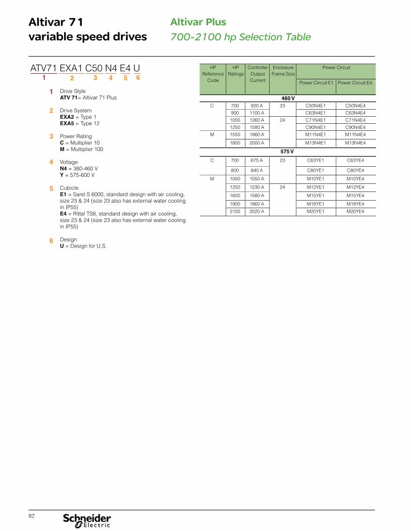
82
Altivar 71variable speed drives 700-2100 hp Selection Table
Altivar Plus
Drive StyleATV 71= Altivar 71 Plus
Drive SystemEXA2 = Type 1EXA5 = Type 12
Power RatingC = Multiplier 10M = Multiplier 100
VoltageN4 = 380-460 V Y = 575-600 V
CubicleE1 = Sarel S 6000, standard design with air cooling, size 23 & 24 (size 23 also has external water cooling in IP55)E4 = Rittal TS8, standard design with air cooling, size 23 & 24 (size 23 also has external water cooling in IP55)
Design U = Design for U.S.
1
2
3
4
5
6
ATV71 EXA1 C50 N4 E4 U1 2 3 4 5 6
HP Reference
Code
HP Ratings
Controller Output Current
Enclosure Frame Size
Power Circuit
Power Circuit E1 Power Circuit E4
460 VC 700 920 A 23 C50N4E1 C50N4E4
900 1100 A C63N4E1 C63N4E4
1000 1260 A 24 C71N4E1 C71N4E4
1250 1580 A C90N4E1 C90N4E4
M 1550 1860 A M11N4E1 M11N4E4
1800 2000 A M13N4E1 M13N4E4
575 V
C 700 675 A 23 C63YE1 C63YE4
800 840 A C80YE1 C80YE4
M 1000 1050 A M10YE1 M10YE4
1250 1230 A 24 M12YE1 M12YE4
1600 1580 A M15YE1 M15YE4
1900 1860 A M18YE1 M18YE4
2100 2020 A M20YE1 M20YE4

83
Altivar 71variable speed drives 700-2100 hp Dimensions
Altivar Plus

84
Altivar 71variable speed drives 700-2100 hp Dimensions
Altivar Plus

85
Altivar 71variable speed drives 700-2100 hp Dimensions
Altivar Plus
Frame Size 24

86
Altivar 71variable speed drives
Quality Assurance
Quality AssuranceThis document communicates a summary of the processes, procedures and quality assurance that are in place for the manufacturing of the Altivar 71. Altivar 71 drives are produced in ISO certified facilities. Customers can be assured that these processes and procedures are followed. Audits conducted by third party representatives verify documented processes and procedures are followed and provide certification to ISO 14001. Schneider Electric utilizes quality assurance processes and procedures to verify the integrity of components and the assembly process. Data is gathered on each unit and tracked via the unique serial number of each unit during the manufacturing process. The document was not intended to imply this data is available in a format that could be easily communicated externally nor that a written report is generated for each product.
Outline of Test Process and ProceduresPrinted circuit board testing, dielectric testing, preliminary memory and functional test, unit operation with burn-in testing, and final verification testing are conducted at various points in the manufacturing process for each drive. All aspects of these tests during the assembly are logged electronically for internal tracking purposes. Each unit is checked and product conformance status is recorded at each test station. Appropriate conformance information is carried in nonvolatile memory within each unit. The sequence of testing is monitored. Each test station requires a successful bar code scan on entry to validate that each drive has successfully completed any prerequisite test stations.
In addition to the processes and procedures detailed below, each test station has a visual quality inspection check list. This check list includes a physical inspection for proper connections, power component polarities, proper assembly torques, mechanical integrity, and proper documentation.
Printed Circuit Board Testing Printed circuit boards used in the assembly of the ATV71 undergo testing as a part of the board assembly. These tests include:
� In-circuit, component level testing � Functional power-on testing � Thermal-cycle stress testing � High-potential test applied to high voltage boards
Dielectric Testing (Hi Pot Test)This test verifies the dielectric withstand between customer connection points and ground to validate that required isolation barriers are intact. Isolation barriers are typically tested for a duration of one (1) second during which a high voltage is applied according to lEC 61800-5-1 standard. This station is also used to verify placement of the power circuit connections.
Preliminary memory and functional testingDuring this test, the unit’s on-board communication port is utilized to read internal memory and set aside a portion of memory to track the processes preformed on the drive and its main components. Each tracked process must have been completed successfully to proceed. These include:
� Supplier preformed tests of printed circuit boards with on-board memory. � Successful drive hi-pot test.
A preliminary test is run to verify: � Heatsink ground screw presence � RFI filter jumper setting � DC bus jumper presence � EEPROM test � Product rating verification � Initial rating verification � Analog input calibration � Analog output calibration � Self test (verification of the display board and control terminal board.) � Pre-motor test

87
Altivar 71variable speed drives
Quality Assurance
Unit operation and burn-in testingBurn-in testing involves four aspects - (I) sample plan, (II) thermal profile, (III) electri-cal cycling, and (IV) load cycling. Each will vary slightly by the equipment available at each production facility and by the current quality results experienced by each production facility.
(I) Sample Plan
Burn-in is sampled at a rate that varies from 5% to 100%. The rate is based on cur-rent quality results for each production facility. Each production facility is required to burn-in at sample rates determined by the model to the left.
(II) Thermal Profile
Constant elevated temperature of 60 oC for two hours during which the drive is sub-jected to electrical cycling for the entire duration of the thermal profile.
(III) Electrical Cycles
The electrical cycle runs concurrently with the thermal profile. An electrical cycle energizes and de-energizes the drive by connecting and removing AC input power. The drive is energized for the duration of a load cycle (typically 4 minutes) and de-energized to allow the drive power supply to shut down (typically 40 seconds). This cycle repeats continuously during the portions of the thermal profile indicated above. This cycle is repeated continuously during the thermal profile.
(IV) Load Cycles
Drives are connected to an inertial motor load during burn-in. When the drive is energized, the drive is cycled between high speed forward and reverse operations. Load cycles are made at a minimum interval of 10 seconds. Acceleration and de-celeration rates are 0.1s (minimum). The rates are selected to maximize transition stress.
Monitoring during burn-in cycleThe drive fault register and drive speed are monitored conditions during the load cycle. A detected fault or failure to attain commanded speed results in a test failure.
Final verification testingThis test validates proper operation after burn-in and prepares the drive settings for customer shipment. The following checks are made:
� DC bus pre-charge check � Communication port test � Product model verification � 7 segment LED display check � DC charge LED check l � CPU version check � DC bus level check � Fan operation test � Nominal load characteristic check � Over current test � Ground fault trip test � Brake transistor off check � Brake transistor on check � Set factory default configuration
This document provides information regarding the quality assurance processes and procedures that are in place for the manufacturing of Altivar 71. These are in place to monitor and confirm the quality of the product line that has been designed in from the outset.

88
Solutions for every stage of your equipment’s life cycle Schneider Electric™ provides services far beyond meeting your immediate needs for application or equipment repair. We take a long-term, holistic approach to deter-mine your facility and operational needs and develop a strategy for improving the performance of your people, systems, and processes.
Schneider Electric provides services from system design and consulting, to main-tenance support, modernization of your installation, and project delivery. Schneider Electric provides the people, tools, and processes to help maximize your business’s infrastructure.
Our expertise enables you to cut costs, reduce energy consumption, and keep your systems up and running through routine maintenance, added enhancements, and migrations to new state-of-the-art functionality.
>When it comes to your automation equipment, we can help you
� Increase productivity � Improve reliability and safety � Mitigate risk and limit downtime � Keep equipment up to date � Extend the life of your installed base � Cut costs and increase savings � Improve your return on investment
> Start-up and commissioningExpert installation support to provide assistance in the start-up of your new system. Service includes a comprehensive power-up and diagnostic check on system com-ponents to minimize risk and optimize operation.
> Technical trainingTraining offered on-site, off-site, or online for Schneider Electric automation products taught by professional instructors with up-to-date knowledge of our latest hardware and software.
> Remote technical supportComprehensive online and phone support from experts specially trained on Schnei-der Electric drive products, helping to reduce downtime and costs and optimize your system’s life cycle.
> On-site technical supportSupport service to perform regular maintenance, upgrades, and conversion assis-tance, small application and programming assistance, on-the-job training, equip-ment repair, support and troubleshooting, even in emergency situations.
> Preventative maintenanceMaintenance programs to scan for, and proactively detect, potential issues or problems with your automation system to help you avoid the costs of unscheduled downtime and short equipment service life. Also serves to extend the life of your installed base by using our services to properly maintain your equipment.
> Industrial repair servicesRepair capabilities for over 400,000 part numbers from more than 2,500 manufac-turers at our Greensboro, NC repair facility. Repair is available for both Schneider Electric and non-Schneider Electric equipment.
> Spare parts managementSave money and reduce downtime through our parts management program. An on-site assessment is performed to determine parts and inventory levels needed to ensure proper system operation and reduce downtime and inventory costs.
> Migration and modernizationRealize the productivity benefits of the latest Schneider Electric automation technol-ogy by using our assessment tools to identify and implement replacement of your legacy automation products, regardless of brand. We make extensive use of exist-ing hardware and wiring for a cost-effective solution with minimal downtime.
> Software renewalsAccess the latest software, firmware, and custom options to ensure you always have the latest functionality available to optimize your system’s life cycle.
> Extended warrantyExtend your Schneider Electric standard manufacturer warranty from one year to five years. Protection plans are tailored to your needs reducing costs and out-of-service time.

89
The Altivar family of variable speed AC drives and the Altistart family of soft starts presents the most advanced and user-friendly solutions in the marketplace. Featuring proprietary motor control algorithms to achieve optimal reaction times and complete scalability to match your applica-tion requirements for speed, size, and protection, the complete line of Altivar and Altistart products provides the flexibility and performance to:
Meet the needs of a broad range of industries, including HVAC, pump, material handling, hoisting, packaging and many more. Reduce your energy costs using proprietary energy-saving technologies available only from Schneider Electric. Improve your up-time by simplifying installation, commissioning and maintenance by providing advanced diagnostics, industry-leading
voltage ride thru capability and seismic qualified products.
We also work with you to deliver the benefits of a global service and support of a global service and support organization to further increase the value of working with Schneider Electric. Our product specialists, industry experts, distributors, partners, and the countless other members of the Schneider Electric family are dedicated to helping you make the most of your energy everyday. Contact your local sales representative today to learn how Schneider Electric can improve operational performance and help your business to achieve a competitive advantage. Or visit www.schneider-electric.com
Talk to someone you can trust
Toll Free 1-888-778-2733E-mail [email protected] 919-217-6508
>Schneider Electric Service (On-Site)The Schneider Electric Services division is committed to providing quality on-site service that consistently meets customer expectations. Services responds to your requests, seven days a week, 24 hours a day. Phone 1-888-778-2733
>Schneider Electric Customer TrainingSchneider Electric offers a variety of instructor-led skill enhancing and technical product training programs for customers. For a complete list of drives/soft start training with dates, locations, and pricing please call:Phone 978-975-9306Fax 978-975-2821
>Customer Care Center(Assist with stock checks, claims, and order management)To provide additional support, Schneider Electric has rolled out new Technical Ser-vice Representatives in local offices which have the strongest needs.Due to time zone changes and different time operation requirements business operation times vary.Phone 888-778-2733Fax 888-329-9773
>Drive Product Support GroupFor support and assistance, contact the Drive Product Support Group. The Drive Product Support Group is staffed from 8:00 am until 8:00 pm Eastern time to assist with product selection, start-up, and diagnosis of product or application problems. EMERGENCY Technical phone support is available 24 hours a day, 365 days a year.

8800CT1401March 2014 - V1.0
The information provided in this documentation contains general descriptions and/or technical characteristics of the performance of the products contained herein. This documentation is not intended as a substitute for and is not to be used for determining suitability or reliability of these products for specific user applications. It is the duty of any such user or integrator to perform the appropriate and complete risk analysis, evaluation and testing of the products with respect to the relevant specific application or use thereof. Neither Schneider Electric nor any of its affiliates or subsidiaries shall be responsible or liable for misuse of the information contained herein.
© 2014 Schneider Electric. All rights reserved. Schneider Electric, Altistart, Altivar, TeSys, Lexium, Magelis, SoMove, SoMachine, Modicon, PowerPact and Powerlogic are trademarks owned by Schneider Electric Industries SAS or its affiliated companies. All other trademarks are the property of their respective owners.
Design: Schneider ElectricPhotos: Schneider Electric
Schneider Electric USA, Inc.8001 Knightdale Blvd. Knightdale, NC 27545
USA Customer Care CenterTel: 888-778-2733
Schneider Electric Industries SAS
Copyright © 2022 FDOKUMEN