Advanced Grid Connected Solar Variable Speed Drive for ...
9
MANSOURA ENGINEERING JOURNAL, (MEJ), VOL. 46, ISSUE 4, DECEMBER 2021 E: 1 Mansoura University Faculty of Engineering Mansoura Engineering Journal (Ser. NO. BFEMU-2108-1147) Received: (10 August, 2021) - Revised: (17 October, 2021) - Accepted: (20 October, 2021) *Corresponding Author: Ahmed M. Ismaiel, Teaching Assistant in the Electrical Engineering Department, Suez Canal University, Ismailia, Egypt, (email: [email protected]). Basem E. Elnaghi, Associate Professor in the Electrical Engineering Department, Suez Canal University, Ismailia, Egypt, (email: [email protected]). Reham H. Mohamed, Assistant Professor in the Electrical Engineering Department, Suez Canal University, Ismailia, Egypt, (email: [email protected]). LIST OF ABBREVIATIONS : Torque current component : Flux current component : Rotor Flux : Reference Torque : Desired speed : Time constant : Mutual inductance : Rotor flux position : Slip angle : Rotor angle Advanced Grid Connected Solar Variable Speed Drive for Three Phase Asynchronous Motors Ahmed M. Ismaiel*, Basem E. Elnaghi and Reham H.Mohammed KEYWORDS: Solar powered Asynchronous motor, MPPT, FOC, Incremental Conductance, Photovoltaic Panels Abstract— In this work, solar energy is used efficiently by running photovoltaic (PV) panels at their maximum power point (MPP) to power an asynchronous motor. Such methods are extremely beneficial in situations where other sources, such as grid electricity and other renewable sources, are limited. These asynchronous motors are more cost effective since they require less maintenance and operation cost. The primary elements of solar-powered Asynchronous motor system are the solar panel, control board, and motor set. The suggested system utilizes Asynchronous motor drive to provide power from solar energy to a motor by converting the DC electric power supplied by a PV array to AC electric power using an inverter. A solar panel with a power producing capacity of 5 kW is employed in the proposed work. The asynchronous motor utilized has a power rating of 4.5 HP. Three control techniques are used in this research Carrier based Pulse Width Modulation (PWM), Field Oriented Control (FOC), and Maximum Power Point Tracking (MPPT). This paper discusses computational demonstrating technique of MPPT like Incremental Conductance (Inc.) with Field Oriented Control Drive and compare it to the existing model of Perturb & observe with Field Oriented Technique. The control techniques are demonstrated by using Matlab/Simulink. The simulation results show that the controllers based on Incremental Conductance methods with Field Oriented Control are more effective for each performance index because they have a smaller overshoot value, a shorter rising time, and a high dynamic response.
-
Upload
khangminh22 -
Category
Documents
-
view
2 -
download
0
Transcript of Advanced Grid Connected Solar Variable Speed Drive for ...

MANSOURA ENGINEERING JOURNAL, (MEJ), VOL. 46, ISSUE 4, DECEMBER 2021 E: 1
Mansoura University
Faculty of Engineering
Mansoura Engineering Journal
(Ser. NO. BFEMU-2108-1147)
Received: (10 August, 2021) - Revised: (17 October, 2021) - Accepted:
(20 October, 2021)
*Corresponding Author: Ahmed M. Ismaiel, Teaching Assistant in the
Electrical Engineering Department, Suez Canal University, Ismailia, Egypt, (email: [email protected]).
Basem E. Elnaghi, Associate Professor in the Electrical Engineering
Department, Suez Canal University, Ismailia, Egypt, (email:
Reham H. Mohamed, Assistant Professor in the Electrical Engineering
Department, Suez Canal University, Ismailia, Egypt, (email:
LIST OF ABBREVIATIONS
: Torque current component
: Flux current component
: Rotor Flux
: Reference Torque
: Desired speed
: Time constant
: Mutual inductance
: Rotor flux position
: Slip angle
: Rotor angle
Advanced Grid Connected Solar Variable Speed
Drive for Three Phase Asynchronous Motors
Ahmed M. Ismaiel*, Basem E. Elnaghi and Reham H.Mohammed
KEYWORDS:
Solar powered
Asynchronous motor,
MPPT, FOC,
Incremental
Conductance,
Photovoltaic Panels
Abstract— In this work, solar energy is used efficiently by running
photovoltaic (PV) panels at their maximum power point (MPP) to power an
asynchronous motor. Such methods are extremely beneficial in situations where
other sources, such as grid electricity and other renewable sources, are limited.
These asynchronous motors are more cost effective since they require less
maintenance and operation cost. The primary elements of solar-powered
Asynchronous motor system are the solar panel, control board, and motor set.
The suggested system utilizes Asynchronous motor drive to provide power from
solar energy to a motor by converting the DC electric power supplied by a PV
array to AC electric power using an inverter. A solar panel with a power
producing capacity of 5 kW is employed in the proposed work. The
asynchronous motor utilized has a power rating of 4.5 HP. Three control
techniques are used in this research Carrier based Pulse Width Modulation
(PWM), Field Oriented Control (FOC), and Maximum Power Point Tracking
(MPPT). This paper discusses computational demonstrating technique of MPPT
like Incremental Conductance (Inc.) with Field Oriented Control Drive and
compare it to the existing model of Perturb & observe with Field Oriented
Technique. The control techniques are demonstrated by using Matlab/Simulink.
The simulation results show that the controllers based on Incremental
Conductance methods with Field Oriented Control are more effective for each
performance index because they have a smaller overshoot value, a shorter rising
time, and a high dynamic response.

E: 2 AHMED M. ISMAIEL, BASEM E. ELNAGHI AND REHAM H.MOHAMMED
I. INTRODUCTION
n 2011, According to the International Energy Agency,
solar energy technology will have a major influence on
its long-term advantages which is extensively
distributed across the world since it is a clean, inexhaustible,
self-sufficient resource, and its development is inexpensive
because it is environment friendly, thereby benefiting mankind
[1]. Photovoltaic powered motors have experienced
considerable attention in solar energy technologies. PV
powered motors use DC motor in many places in the world
[2]. As mentioned in different literatures [3],[5], photovoltaic
(PV) technology has several benefits. When compared to other
non-ordinary vitality sources, the advantages of a sun-oriented
PV reference frame are as follows: it retains the continuously
enduring sun-powered vitality at no cost, it is eco-friendly
without causing any kind of pollution in the environment, and
It provides a low-noise operation and minimal support. The
sun-powered PV module straightforwardly transforms the sun
vitality into DC electric power. Using power molding
technologies, the produced DC electric power is subsequently
converted to the desired frame. The power molding unit
includes a converter or inverter, depending on the application.
Because of the government's sponsorship, the use of solar-
powered motors has grown. The government's support
lowered the cost of photovoltaic solar panels. Various
approaches have been explored in the past to increase the
performance of solar pumps [23-24]. Electrical array
reconfiguration techniques were utilized. The
used controller provides a simplified solution by providing a
wide range of irradiance levels for supplying enough current
to start the motor [6]. PV-fed DC motors have previously been
used to power the pumping system. DC motor control methods
are quite simple. By utilizing the most maximum power point
tracking technique, the highest power can be obtained from
the PV solar array [7]. However, asynchronous motors are
gradually replacing DC motors since they have numerous
benefits over DC motors, such as the proximity of the brushes
and commutator, and are less dependable. The system in this
case is to provide power to an asynchronous motor drive by
converting the DC electric power supplied by the PV panels to
AC power using an inverter. The output power taken from the
inverter is given to the Asynchronous motor. It is always
preferred that the PV panels operate at their maximum power
point (MPP), which allows the PV electricity to be used
efficiently [8-9]. The voltage source inverter (VSI) is used in
control preparation applications such as static compensators,
AC motor drives, and dynamic front end converters. In AC
motor drives application, variable voltage and variable
recurrence are necessary to control the motor speed. VSI is
employed in power processing applications including AC
motor drives, static compensators, and active front end
converters. Variable frequency and variable voltage are
necessary in the use of AC motor drives to regulate the motor
speed. The DC link voltage feeding the inverter is fixed. PWM
waveforms for a voltage source inverter may be produced by
contrasting three-stage adjustment signals. and a typical
triangular bearer (triangle-examination strategy) [13-16].
Alternatively, the space vector method might be used to
generate PWM. The information of the rotor transition
position edge in relation to the stator is the key to Field-
Oriented Control. It is conceivable to register the edge from
shaft position data, given that other motor parameters are
known. This methodology is currently presented by large
name “Field Oriented Control" (FOC) [17]. Instead of the
three-phase currents that are normally given to an
asynchronous motor, two perpendicular currents can be used
to control it. These two perpendicular currents called
quadrature current ( ) and direct current ( ) are in charge of
controlling torque component and flux component
respectively in the motor.
II. LITERATURE REVIEW
A significant amount of researches have been conducted
on PV solar energy, Asynchronous motor speed drive,
pumping applications, and so on. This section has given some
of the closely connected studies.
A. Dead-Time Effect on Inverter Characteristics
The study provided by N Urasaki et al. [18] discusses the
influence of dead-time on inverter characteristics. It is
addressed how to correct for dead time in asynchronous motor
drives. The disturbance voltage generated by non-ideal
inverter effects is utilized to determine the dead time
compensation voltage (DTCV) amplitude. The adaptive
DTCV minimizes the error between theoretical and actual
power, according to the findings of the experiments.
B. Volt/Hz Control and MPPT
The study provided by Muljadi's [19] demonstrates a
photovoltaic (PV) water pumping system utilized in
agriculture and households. This method is quite popular in
remote locations since it makes use of solar energy, which is
widely exists all around the world. This system includes water
pump, asynchronous motor, PV array and a variable speed
inverter based on V/f control strategy. The inverter operates at
variable frequency, taking input from the PV array and
feeding it to the asynchronous motor, which then varies the
output of the pump by creating a six-step quasi-square wave.
Because of the usage of a six-step square wave inverter, the
inverter also functions as a peak power tracker, reducing the
number of switches. The benefit of this system is that it
protects the system in the event of a short circuit since the
current is restricted to the top limit of the PV array current.
This model presented in this research does not contain a
battery module, which makes the system more effective
because the pump uses the full produced power.
C. Field Oriented Control Algorithm
The work proposed by Yulin Zhang et [20] at
"Asynchronous motor control system based on FOC
algorithm." This control depends on designs which change a
I
MANSOURA ENGINEERING JOURNAL, (MEJ), VOL. 46, ISSUE 4, DECEMBER 2021 E: 3
three phase time and speed subordinate framework into a two
coordinate (d and q coordinates) time independent reference.
These designs result in a control framework similar to that of a
DC machine. Field oriented controlled machines need two
constants as information references: the torque component
(lined up with the q co-ordinate) and the transition component
(lined up with d coordinate). As Field Orientated Control is
just founded on designs the control structure handles prompt
electrical amounts. That leads the control to be precise in each
working operation (transient and steady state) and free of the
constrained data transmission scientific model.
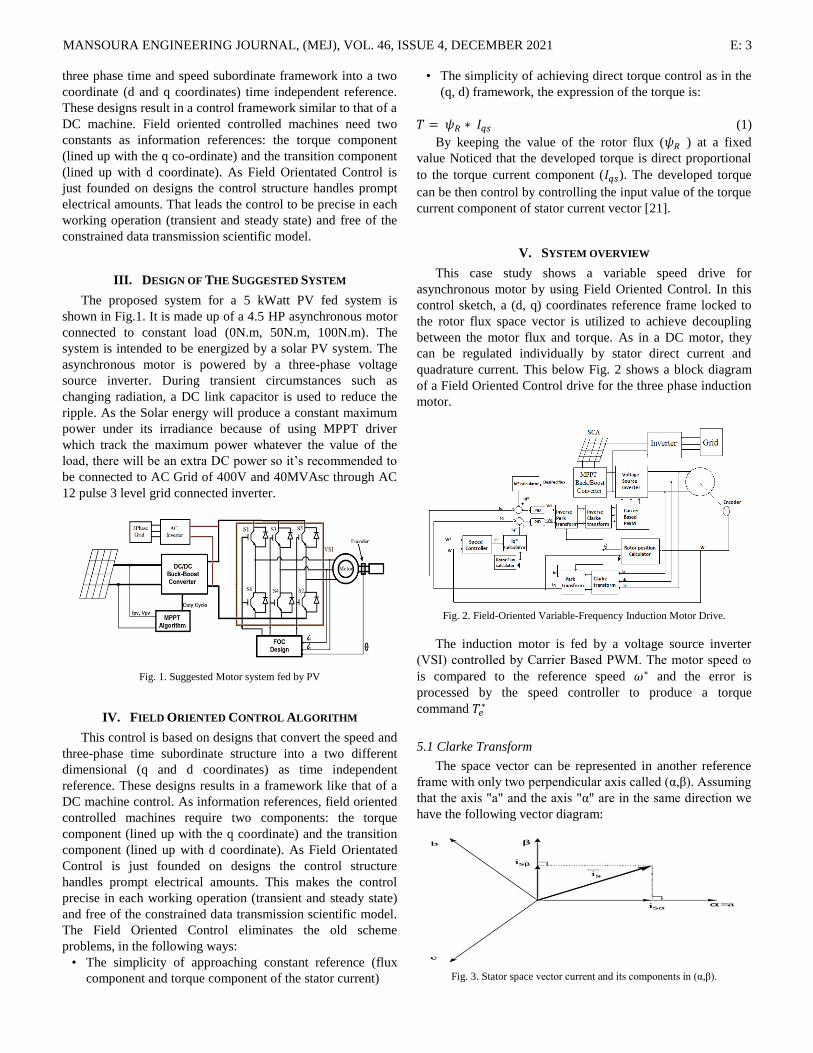
III. DESIGN OF THE SUGGESTED SYSTEM
The proposed system for a 5 kWatt PV fed system is
shown in Fig.1. It is made up of a 4.5 HP asynchronous motor
connected to constant load (0N.m, 50N.m, 100N.m). The
system is intended to be energized by a solar PV system. The
asynchronous motor is powered by a three-phase voltage
source inverter. During transient circumstances such as
changing radiation, a DC link capacitor is used to reduce the
ripple. As the Solar energy will produce a constant maximum
power under its irradiance because of using MPPT driver
which track the maximum power whatever the value of the
load, there will be an extra DC power so it’s recommended to
be connected to AC Grid of 400V and 40MVAsc through AC
12 pulse 3 level grid connected inverter.
Fig. 1. Suggested Motor system fed by PV
IV. FIELD ORIENTED CONTROL ALGORITHM
This control is based on designs that convert the speed and
three-phase time subordinate structure into a two different
dimensional (q and d coordinates) as time independent
reference. These designs results in a framework like that of a
DC machine control. As information references, field oriented
controlled machines require two components: the torque
component (lined up with the q coordinate) and the transition
component (lined up with d coordinate). As Field Orientated
Control is just founded on designs the control structure
handles prompt electrical amounts. This makes the control
precise in each working operation (transient and steady state)
and free of the constrained data transmission scientific model.
The Field Oriented Control eliminates the old scheme
problems, in the following ways:
• The simplicity of approaching constant reference (flux
component and torque component of the stator current)
• The simplicity of achieving direct torque control as in the
(q, d) framework, the expression of the torque is:
(1)
By keeping the value of the rotor flux ( ) at a fixed
value Noticed that the developed torque is direct proportional
to the torque current component ( ). The developed torque
can be then control by controlling the input value of the torque
current component of stator current vector [21].
V. SYSTEM OVERVIEW
This case study shows a variable speed drive for
asynchronous motor by using Field Oriented Control. In this
control sketch, a (d, q) coordinates reference frame locked to
the rotor flux space vector is utilized to achieve decoupling
between the motor flux and torque. As in a DC motor, they
can be regulated individually by stator direct current and
quadrature current. This below Fig. 2 shows a block diagram
of a Field Oriented Control drive for the three phase induction
motor.
Fig. 2. Field-Oriented Variable-Frequency Induction Motor Drive.
The induction motor is fed by a voltage source inverter
(VSI) controlled by Carrier Based PWM. The motor speed ω
is compared to the reference speed and the error is
processed by the speed controller to produce a torque
command
5.1 Clarke Transform
The space vector can be represented in another reference
frame with only two perpendicular axis called (α,β). Assuming
that the axis "a" and the axis "α" are in the same direction we
have the following vector diagram:
Fig. 3. Stator space vector current and its components in (α,β).

E: 4 AHMED M. ISMAIEL, BASEM E. ELNAGHI AND REHAM H.MOHAMMED
The projection that modifies the three phase system into
the (α, β) two orthogonal dimension system is presented
below:
(2)
√
√
(3)
We obtain a two coordinate system , which is still
based on time and speed.
5.2 Park Transform
This is the most essential transformation in the Field
Oriented Control. In fact, this projection changes a two phase
perpendicular system (α,β) in the (d,q) rotating reference
frame. If we consider the d axis lined up with the rotor flux,
the next diagram shows, for the current vector, the relationship
from the two reference frame:
Fig. 4. Stator space vector current and its components in (α, β) and in
the d, q rotating reference frame with angle θ.
Where, θ is the rotor flux position. The flux and torque
components of the current vector are determined by the
following equations:
(4)
(5)
These components rely on the current vector (α,β)
components and on the rotor flux position; if we know the
exact rotor flux position then, by this projection, the d,q
components can be estimated.
We obtain a two co-ordinate system with the following
characteristics:
Two co-ordinates don't depend on time.
With (flux component) and (torque component) the
direct torque control is possible and simple.
5.3 Flux Estimator
This element is used to calculate the rotor flux in the
motor. This calculation depends on motor equation synthesis
[10].
(6)
5.4 Rotor Flux Position Estimator
This element is used to estimate the exact position of rotor
field using the following equations,
(7)
(8)
5.5 Carrier Based Pwm
The most generally utilized strategy for pulse width
modulation is performed. This technique is otherwise called
the sinusoidal (SPWM), triangulation, sub-harmonic, or sub-
oscillation strategy [11, 12]. Sinusoidal adjustment depends on
triangular transporter signal as appeared in Fig. 5. In this
technique three reference signals UAc, UBc, UCc are
compared with triangular bearer signal Ut, which is common
to every one of the three phases. Along these lines the
coherent sign SA, SB, SC are created, which characterize the
exchanging moments of the power transistors as is appeared in
Fig. 6.
Fig. 5. Block diagram scheme for carrier based sinusoidal PWM.
Fig. 6. Basic waveforms of carrier based sinusoidal PWM
5.6. Speed Controller
The control law used for this strategy is given by,
(9)
(10)
Its output is regulated by PI controller gains (Kp and Ki)
based on a set of rules to maintain excellent control
performance even in the existence of parameter variation and
drive nonlinearity. At starting mode the high value of the error
is amplified across the PI controller provoking high variations
in the desired torque. If Kp and Ki of the PI controller exceed

MANSOURA ENGINEERING JOURNAL, (MEJ), VOL. 46, ISSUE 4, DECEMBER 2021 E: 5
a certain value, the changes in the desired torque become too
high and will destabilize the system. To override this problem,
a limiter placed after the PI controller is used. When properly
set, this limiter causes the speed error to be kept within limits,
resulting in smooth fluctuations in the required torque even
when the PI controller gains are quite large [20-23]. The
Simulink model of PI controller is designed as shown in Fig.
5. The model is formed with gain coefficients Kp and Ki tuned
at 40 and 50 respectively. The motor to be controlled is in a
closed loop with the FOC block, which creates inverter
switching signals to achieve the motor's target speed.
Fig. 7. Simulink models of conventional PI speed controller
VI. MPPT TECHNIQUES
A. Perturb & Observe
The perturb and observe approach has been widely utilized
as it is simple to implement. The P&O technique directs the
PV system to reach the MPP by raising or reducing output
voltage of the PV panel. A DC/DC converter is installed
between the solar panel and the load to adjust the voltage of
the PV panel. The duty cycle of the converter is adjusted to
change the voltage of the PV panels. As its name implies,
P&O method performs perturbation of Vpv and observe of its
effect on the change of the output power of panel statement by
changing duty cycle (D) of the converter. The control flow
chart for the P&O technique is shown in Fig. 8, where k is an
integer value 1, 2, 3,……..
Fig. 8. Flowchart of the P&O algorithm
B. Incremental Conductance
The P-V characteristic curve was used to create
Incremental Conductance. This method was created in 1993 to
address some of the limitations of the P&O algorithm. The
incremental conductance technique is regarded as one of the
most effective ways for tracking module MPP. Maximum
power point is determined using the rate of change of power
with respect to voltage ( ). Along with the above
derivative, the relation between
&
is an important
factor in the incremental conductance methodology (InC)
attempts to enhance the tracking time and produce more
energy in a changing environment due to irradiation [3]. By
using the relation between and– , the MPP can be
easily estimated. If is negative then MPP is lies to the
right of the most recent position and if it’s positive, the MPP is
on the left of the most recent position [15], [25-26]. The
equations of Inc. method is:
Fig. 9. Flowchart of the InC. algorithm
VII. SIMULINK MODEL
Fig. 10 shows the Simulink model of a Field Oriented
Control drive for the three phases, 4.5 HP, 460 V, Two-pole,
60 Hz Asynchronous motor fed from 5 kwatt solar cell array
(SCA).

E: 6 AHMED M. ISMAIEL, BASEM E. ELNAGHI AND REHAM H.MOHAMMED
Fig. 10. Simulink model of speed controller system for Squirrel cage
Asynchronous Motor (SCIM).
Fig. 11 shows the PV module characteristic curves under
100W/m2, 500W/m
2 and 1000W/m
2.
(a)
(b)
Fig. 11. PV Solar module at 1000W/m2, 500 W/m2 and 100W/m2.
(a) I-V curve, (b) P-V curve.
VIII. SIMULATION RESULTS
To simulate the machine in Simulink, the Simulink model
first has to be initialized so that it will get all the machine
parameters. The Asynchronous motor used here is 4.5 HP, 460
V, Two-pole, 60 Hz motor. The speed has been noticed for 4
sec for each model. The solar irradiance applied on PV solar
array is described in Fig. 12. The irradiance has been reduced
in time equal to 2sec. The results of output speed at no load by
using Incremental Conductance and Perturb & observe
algorithms with Proportional Integral Speed controller based
on Field Oriented Control algorithm are shown in Fig. 13.
Fig. 12. Simulation of the motor speed for the reference speed
20 rad/s and no-load.
Fig. 13. Simulation of the motor speed for the reference speed
20 rad/s and no-load.
Fig. 14 shows how the incremental conductance technique
will result in faster torque response at the transient state but it
has nearly more than twice the overshoot torque of the P&O
technique. This will cause lower settling time and faster speed
response.
(a)
(b)
Fig. 14. Torque simulation for the reference speed 20 rad/s and no load.
(a) Perturb & Observe, (b) Incremental Conductance.

MANSOURA ENGINEERING JOURNAL, (MEJ), VOL. 46, ISSUE 4, DECEMBER 2021 E: 7
Fig. 15 shows the produced DC power of the buck-boost
converter. It’s noticed that incremental conductance has faster
rising time for the DC power than the P&O. P&O technique
has higher steady state ripple as compared to incremental
conductance. At time equal to 2sec, when the solar irradiance
has been reduced from 1000W/m2
to 800W/m2, the DC power
will be reduced from 4.5kw to 3.6kw and there is transient
small ripple spike in DC power in case of P&O technique.
(a)
(b)
Fig. 15. Produced DC power of DC/DC buck boost converter simulation
for the reference speed 20 rad/s and no load.
(a) Perturb & Observe, (b) Incremental Conductance.
It’s noticed that transmitted power to the grid in case of
incremental conductance has faster settling time as compared
to that of P&O as shown in Fig. 16. P&O technique has higher
steady state ripple as compared to incremental conductance.
At time equal to 2sec, when the solar irradiance has been
reduced from 1000W/m2
to 800W/m2, the DC power will be
reduced from 4.5kw to 3.6kw and there is transient small
ripple spike in DC power in case of P&O technique.
(a)
(b)
Fig. 16. Grid transmitted power simulation for the reference speed
20 rad/s and no load. (a) Perturb & Observe, (b) Incremental Conductance.
It’s noticed that DC link voltage of the system using
incremental conductance has faster rising time than the system
using P&O as shown in Fig. 17. P&O technique has higher
steady state ripple as compared to incremental conductance.
At time equal to 2sec, the DC voltage stayed constant as 496V
but there is transient small ripple spike in DC voltage in case
of P&O technique, when the solar irradiance has been reduced
from 1000W/m2 to 800W/m
2.
(a)
(b)
Fig. 17. DC Link Voltage simulation for the reference speed 20 rad/s and no
load. (a) Perturb & Observe, (b) Incremental Conductance.
Fig. 18 shows how the incremental conductance has higher
inrush transient current as compared to P&O technique but
InC. is much faster for reaching steady-state than that of the
P&O technique. That’s because of the slow rising time of
P&O as compared to InC.

E: 8 AHMED M. ISMAIEL, BASEM E. ELNAGHI AND REHAM H.MOHAMMED
(a)
(b)
Fig. 18. Stator Current simulation for the reference speed 20 rad/s and no
load. (a) Perturb & Observe, (b) Incremental Conductance.
The dynamic performance analysis with increasing the
mechanical load (0N.m, 50N.m and 100N.m) value is
described in TABLE I. TABLE I shows that the incremental
conductance is much better at higher load as the steady state
error for incremental conductance technique is lower than the
one of perturb & observe technique at higher load torque.
IX. CONCLUSION
MATLAB/Simulink was used to create a mathematical
model of a 5 KW solar panel in this research. This model is
used to achieve the maximum power of the PV solar array by
using two different techniques. The speed control of the
Asynchronous motor for industrial application is achieved by
using very brand new technique (Field Oriented Control) to
adjust the motor speed based on speed error, and the power of
PV solar system power is regulated by two different
techniques (Incremental Conductance and Perturb & Observe).
Incremental Conductance and Perturb & Observe MPPT
techniques are reviewed, as well as their simulation results. At
time equal to 2sec, when the solar irradiance has been reduced
from 1000W/m2
to 800W/m2, the DC voltage stayed constant
as 496V and DC power drops from 4.5kw to 3.6kw but there
is transient small ripple spike in DC power in case of P&O
technique. It has been demonstrated that the Incremental
conductance technique outperforms the P&O algorithm. These
techniques increase the solar system's dynamics and steady-
state performance, as well as the effectiveness of the DC-DC
converter system. From this work, it can be inferred that for
rural areas where there is no electricity, the PV provided
Asynchronous motor framework may be introduced to meet
the need for water for irrigation or any industrial application
of Asynchronous motor. The PV-fed Asynchronous motor
using the control approaches presented in this work may be
regarded an efficient system since it provides decoupling
between flux and torque control as well as direct flux control
for the asynchronous motor using field oriented control
technique.
X. APPENDIX
TABLE II shows the specification parameter for both
asynchronous motor and PI speed controller.
AUTHORS CONTRIBUTION
Solar variable speed asynchronous motor drive based on
maximum power tracking field oriented control is
implemented with Matlab/Simulink. The proposed paper
shows the effect of two different techniques on field oriented
control speed drive for asynchronous motor.
Ahmed M. Ismaiel is responsible for design and analysis
the propose system.
Basem E. Elnaghi is responsible for drafting the article.
Reham H.Mohammed is responsible for investigating the
difference between Perturb and Observe and Incremental
Conductance.
TABLE I
UNITS FOR MAGNETIC PROPERTIES
At
Load
(N.m)
METHOD Rising Time
Tr (ms)
Overshoot
peak
(Rad/s)
0 P&O
InC.
388.355
24.414
4.97
2.14
50 P&O
InC.
450.335
25.153
3.64
2.01
100 P&O
InC.
500.300
25.994
2.83
1.05
TABLE II
SPECIFICATIONS OF ASYNCHRONOUS MOTOR & CONTROLLER
Asynchronous motor
Motor type 4.5 HP, 460V, 60Hz
Stator Resistance, 𝑅𝑠 0.6837 ohm
Rotor Resistance, 𝑅𝑟 0.451 ohm
Stator inductance, 𝐿𝑠 0.004152H
Rotor inductance, 𝐿𝑟 0.004152 H
Mutual inductance, 𝐿𝑚 0.1486 H
Inertia, J 0.05 Kg.m2
No of poles 2
PI speed controller
Proportional gain, P 40
Integral gain, I 50
Solar Array
No. of parallel strings 2
No. of series modules 15
Maximum system power 5kw
Module Maximum Power 213.15
Module open circuit voltage
36.3V
Module Short circuit voltage
7.84A
MANSOURA ENGINEERING JOURNAL, (MEJ), VOL. 46, ISSUE 4, DECEMBER 2021 E: 9
FUNDING STATEMENT:
The author did not receive any financial support of the
research authorship and publication of this article
DECLARATION OF CONFLICTING INTERESTS STATEMENT:
The author declared that there are no potential conflicts of
interest with respect to the research authorship or publication
of this article
REFERENCES
[1] Neymark, Joel, and Ron Judkoff. "International energy agency building
energy simulation test and diagnostic method for heating, ventilating, and air-conditioning equipment models (HVAC BESTEST)"; Volume 1:
Cases E100-E200. No. NREL/TP-550-30152. National Renewable
Energy Lab., Golden, CO.(US), 2002. [2] Halcrow, Sir William. "Small-scale solar powered irrigation pumping
systems: technical & economic review". World Bank (1818 H Street,
NW, Washington DC 20433), 1981. [3] Philip, Jincy, et al. "Control and implementation of a standalone solar
photovoltaic hybrid system." IEEE Transactions on Industry
Applications 52.4 (2016): 3472-3479. [4] An, Le, and Dylan Dah-Chuan Lu. "Design of a single-switch DC/DC
converter for a PV-battery-powered pump system with PFM+ PWM
control." IEEE Transactions on Industrial Electronics 62.2 (2014): 910-921.
[5] Jain, Sachin, et al. "Dual MPPT algorithm for dual PV source fed open-
end winding Asynchronous motor drive for pumping application." Engineering Science and Technology, an International
Journal 19.4 (2016): 1771-1780.
[6] Pires, Vitor, et al. "A grid connected photovoltaic system with a multilevel inverter and a Le-Blanc transformer." International Journal of
Renewable Energy Research (IJRER) 2.1 (2012): 84-91.
[7] Patnaik, B., et al. "Reconfiguration strategy for optimization of solar photovoltaic array under non-uniform illumination conditions." 2011
37th IEEE Photovoltaic Specialists Conference. IEEE, 2011.
[8] Korpale, V. S., D. H. Kokate, and S. P. Deshmukh. "Performance assessment of solar agricultural water pumping system." Energy
Procedia 90 (2016): 518-524.
[9] Gupta, Mukesh, Shivani Johri, and Gaurav Kumar Chaturvedi. "Implementation of high efficiency, high lifetime and low cost converter
for an automatic photovoltaic water pumping station." International Journal of Advanced Engineering Research and Science 3.8 (2016):
236823.
[10] Nazeer, Najna, and T. N. Shahina. "Speed Control For Indirect Vector Control Of Induction Motor Drives At Low Speeds." 2019 2nd
International Conference on Intelligent Computing, Instrumentation and
Control Technologies (ICICICT). Vol. 1. IEEE, 2019. [11] Bose, Bimal K. Modern power electronics and AC drives. Vol. 123.
Upper Saddle River, NJ: Prentice hall, 2002.
[12] Holtz, Joachim. "Pulsewidth modulation for electronic power conversion." Proceedings of the IEEE 82.8 (1994): 1194-1214.
[13] Ramulu, Chinthamalla, et al. "A solar PV water pumping solution using
a three-level cascaded inverter connected Asynchronous motor drive." Engineering Science and Technology, an International
Journal 19.4 (2016): 1731-1741.
[14] Attique, Qamar Muhammad, Yongdong Li, and Kui Wang. "A survey on space-vector pulse width modulation for multilevel inverters." CPSS
Transactions on Power Electronics and Applications 2.3 (2017): 226-
236. [15] Holtz, Joachim. "Pulsewidth modulation for electronic power
conversion." Proceedings of the IEEE 82.8 (1994): 1194-1214.
[16] Narayanan, G. "Synchronised pulsewidth modulation strategies based on space vector approach for Asynchronous motor drives." (2005).
[17] Venugopal, S. Study On Overmodulation Methods For PWM Inverter
Fed AC Drives. Diss. Indian Institute of Science, 2007.
[18] Urasaki, Naomitsu, et al. "On-line dead-time compensation method for
voltage source inverter fed motor drives." Nineteenth Annual IEEE
Applied Power Electronics Conference and Exposition, 2004. APEC'04. Vol. 1. IEEE, 2004.
[19] Muljadi, Eduard. "PV water pumping with a peak power tracker using a
simple six-step square-wave inverter." IEEE Transactions on industry applications 33.3 (1997): 714-721.
[20] Li, Wei, Zhifeng Xu, and Yulin Zhang. "Asynchronous motor control
system based on FOC algorithm." 2019 IEEE 8th Joint International Information Technology and Artificial Intelligence Conference (ITAIC).
IEEE, 2019. [21] Lee, Jae Suk, et al. "Deadbeat direct torque and flux control of interior
permanent magnet synchronous machines with discrete time stator
current and stator flux linkage observer." IEEE Transactions on Industry
Applications 47.4 (2011): 1749-1758. [22] Ji, Deming, et al. "Design of Induction Motor Vector Control Variable
Frequency Speed Regulation System Based on DSP." Electronic Science
& Technology 3 (2016): 10. [23] Massaq, Zakaria, et al. "Double Stage Solar PV Array Fed Sensorless
Vector Controlled Induction Motor for Irrigational Purpose." 2019 7th
International Renewable and Sustainable Energy Conference (IRSEC). IEEE, 2019.
[24] Shukla, Saurabh, and Bhim Singh. "Single-Stage PV-Grid Interactive
Induction Motor Drive with Improved Flux Estimation Technique for Water Pumping With Reduced Sensors." IEEE Transactions on Power
Electronics 35.12 (2020): 12988-12999.
[25] Sharma, Apoorva, Tripurari Nath Gupta, and Mahiraj Singh Rawat. "Grid Connected Solar PV fed Constant Power Water Pumping
System." 2021 International Conference on Intelligent Technologies
(CONIT). IEEE, 2021. [26] Kumari, Rajni, and Ratna Dahiya. "Speed control of solar water
pumping with indirect vector control technique." 2018 2nd International
Conference on Inventive Systems and Control (ICISC). IEEE, 2018.
Title in Arabic:
ثالثي األطىار تغيز هخشاهٌال اثلوحزك الوخقذهت السزعت اثهغيز
Abstract in Arabic:
الشوسيت بكفاءة عي طزيق حشغيل األلىاح في هذا العول ، يخن اسخخذام الطاقت
( لخشغيل هحزك غيز هخشاهي. هذٍ MPPالكهزوضىئيت عٌذ أقصً ًقطت للطاقت )
األساليب هفيذة للغايت في الوىاقف الخي ال حخىفز فيها بسهىلت هصادر كهزبيت أخزي ،
هثل شبكت إهذاداث الطاقت وهصادر الطاقت الوخجذدة األخزي. هذٍ الوحزكاث غيز
الوخشاهٌت أكثز اقخصادا بسبب اًخفاض حكاليف الصياًت والخشغيل. الوكىًاث الزئيسيت
وهحزك لٌظام هحزاث الطاقت الشوسيت الغيز هخشاهٌت هي األلىاح الشوسيت ولىحت الخحكن
الشوسيت إلً الوحزك االلىاح إعطاء الطاقت هي يخن لٌظام الوقخزح ا ل. طبقغيز هخشاهي
غيز الوخشاهي عي طزيق ححىيل الطاقت الكهزبائيت ص بالوحزكاثالوخحكن الخابوساعذة
ح الطاقت اىال .الوخىلذة هي لىحت الكهزوضىئيت إلً طاقت الخيار الوخزدد باسخخذام العاكس
الوحزك غيز الوخشاهي . واث كيلى 5 بها حسخطيع حشويذ بـ الشوسيت الوقخزحت للعول
اسخزاحيجياث ححكن في هذا العول وهي حصاى. يخن اسخخذام ثالد 4.5ة الوسخخذم بقذر
Field Oriented( وPWM) Carrier Pulse width modulationحعذيل
Control (FOC )العظوً الحذ األقصً لٌقطت الطاقت هخخبع (MPPT ٍحٌاقش هذ .)
Perturbالىرقت حقٌياث هخعذدة للعزض الحسابي لخخبع الحذ األقصً لٌقطت الطاقت هثل
& Observe (P&O) وIncremental Conductance (Inc) باسخخذام .Field
Oriented Control يخن حٌفيذ حقٌياث الخحكن باسخخذامMatlab / Simulink .
Incrementalحظهز ًخائج الوحاكاة أى وحذاث الخحكن القائوت علً أساليب
Conductance هعField Oriented Control أكثز فاعليت لكل هؤشز أداءبأًها
ألى لها قيوت حجاوس أصغز ، ووقج صعىد أقصز ، واسخجابت ديٌاهيكيت عاليت.