YASKAWA AC Drive Compact Vector Control Drive V1000
60
advanced ! So easy ! So small ! So 200 V CLASS, THREE-PHASE INPUT : 0.1 to 18.5 kW 200 V CLASS, SINGLE-PHASE INPUT : 0.1 to 3.7 kW 400 V CLASS, THREE-PHASE INPUT : 0.2 to 18.5 kW YASKAWA AC Drive Compact Vector Control Drive V1000
-
Upload
khangminh22 -
Category
Documents
-
view
2 -
download
0
Transcript of YASKAWA AC Drive Compact Vector Control Drive V1000

DRIVE CENTER (INVERTER PLANT)2-13-1, Nishimiyaichi, Yukuhashi, Fukuoka, 824-8511, JapanPhone +81-930-25-2548 Fax +81-930-25-3431http://www.yaskawa.co.jp
YASKAWA ELECTRIC CORPORATIONNew Pier Takeshiba South Tower, 1-16-1, Kaigan, Minatoku, Tokyo, 105-6891, JapanPhone +81-3-5402-4502 Fax +81-3-5402-4580http://www.yaskawa.co.jp
YASKAWA AMERICA, INC.2121, Norman Drive South, Waukegan, IL 60085, U.S.A.Phone +1-800-YASKAWA (927-5292) or +1-847-887-7000 Fax +1-847-887-7310http://www.yaskawa.com
YASKAWA ELÉTRICO DO BRASIL LTDA.777, Avenida Piraporinha, Diadema, São Paulo, 09950-000, BrasilPhone +55-11-3585-1100 Fax +55-11-3585-1187http://www.yaskawa.com.br
YASKAWA EUROPE GmbHHauptstraβe 185, 65760 Eschborn, GermanyPhone +49-6196-569-300 Fax +49-6196-569-398http://www.yaskawa.eu.com E-mail: [email protected]
YASKAWA ELECTRIC KOREA CORPORATION35F, Three IFC, 10 Gukjegeumyung-ro, Yeongdeungpo-gu, Seoul, 07326, KoreaPhone +82-2-784-7844 Fax +82-2-784-8495http://www.yaskawa.co.kr
YASKAWA ASIA PACIFIC PTE. LTD.30A Kallang Place, #06-01 Singapore 339213Phone +65-6282-3003 Fax +65-6289-3003http://www.yaskawa.com.sg
YASKAWA ELECTRIC (THAILAND) CO., LTD.59, 1st-5th Floor, Flourish Building, Soi Ratchadapisek 18, Ratchadapisek Road, Huaykwang, Bangkok 10310, ThailandPhone +66-2-017-0099 Fax +66-2-017-0799http://www.yaskawa.co.th
PT. YASKAWA ELECTRIC INDONESIASecure Building-Gedung B Lantai Dasar & Lantai 1 Jl. Raya Protokol Halim Perdanakusuma, Jakarta 13610, IndonesiaPhone +62-21-2982-6470 Fax +62-21-2982-6471http://www.yaskawa.co.id/
YASKAWA ELETRIC VIETNAM CO., LTD HO CHI MINH OFFICESuite 1904A, 19th Floor Centec Tower, 72-74 Nguyen Thi Minh Khai Street, Ward 6, District 3, Ho Chi Minh City, VietnamPhone +84-8-3822-8680 Fax +84-8-3822-8780
YASKAWA ELETRIC VIETNAM CO., LTD HA NOI OFFICE2nd Floor, Somerset Hoa Binh Hanoi, No. 106, Hoang Quoc Viet Street, Cau Giay District, Hanoi, VietnamPhone +84-4-3634-3953 Fax +84-4-3654-3954
YASKAWA ELECTRIC (CHINA) CO., LTD.22F, Link Square 1, No.222, Hubin Road, Shanghai, 200021, ChinaPhone +86-21-5385-2200 Fax +86-21-5385-3299http://www.yaskawa.com.cn
YASKAWA ELECTRIC (CHINA) CO., LTD. BEIJING OFFICERoom 1011, Tower W3 Oriental Plaza, No.1 East Chang An Ave.,Dong Cheng District, Beijing, 100738, ChinaPhone +86-10-8518-4086 Fax +86-10-8518-4082
YASKAWA ELECTRIC TAIWAN CORPORATION12F, No. 207, Sec. 3, Beishin Rd., Shindian Dist., New Taipei City 23143, TaiwanPhone: +886-2-8913-1333 Fax: +886-2-8913-1513 or +886-2-8913-1519http://www.yaskawa.com.tw
YASKAWA INDIA PRIVATE LIMITED#17/A, 2nd Main, Electronic City, Phase-I, Hosur Road, Bengaluru 560 100, IndiaPhone +91-80-4244-1900 Fax +91-80-4244-1901http://www.yaskawaindia.in
LITERATURE NO. KAEP C710606 08I <8>-0
V1-01-19-06Published in Japan July 2019
In the event that the end user of this product is to be the military and said product is to be employed in any weapons systems or the manufacture thereof, the export will fall under the relevant regulations as stipulated in the Foreign Exchange and Foreign Trade Regulations. Therefore, be sure to follow all procedures and submit all relevant documentation according to any and all rules, regulations and laws that may apply.
Speci�cations are subject to change without notice for ongoing product modi�cations and improvements.
© 2007 YASKAWA ELECTRIC CORPORATION
Certi�ed forISO9001 andISO14001
JQA-EM0202JQA-QMA14913
V1000
advanced !Soeasy !So
small !So
200 V CLASS, THREE-PHASE INPUT: 0.1 to 18.5 kW200 V CLASS, SINGLE-PHASE INPUT: 0.1 to 3.7 kW400 V CLASS, THREE-PHASE INPUT: 0.2 to 18.5 kW
YASKAWA AC DriveCompact Vector Control Drive
V1000

Yaskawa has built a reputation for high performance, functionality, quality, and reliability. To make it even easier to optimize your applications, we present the new V1000.
*: Results from market research on vector drives performed by Yaskawa.
Bringing you the world’s smallest*variable speed drive to stand at the top of its class: V1000
A single drive with so many uses, benefiting your application the more you use it.
Qui
ck a
nd e
asy
inst
alla
tion,
rea
dy
to r
un y
our
app
licat
ion
in n
o tim
e.
You'
ll b
e am
azed
how
sim
ple
it is
to
use.
Top
per
form
ance
for
its c
lass
. Loa
ded
with
func
tions
an
d fe
atur
es in
an
unb
elie
vab
ly s
mal
l pac
kage
!
So advanced!S
o e
asy!
Smalle
st in th
e world
!
2

PUMP
AUTO SHUTTER
PACKAGING
CONVEYOR
FAN
HVAC
FLUID MACHINE See page 8.
COMPACT CONVEYOR See page 9.
A P P L I C A T I O N S
V1000
C O N T E N T S
Even more eye-opening versatility.
Features 4
Application Benefits 8
Software Functions 10
Parameter List 12
Basic Instructions 16
Product Lineup 18
Model Selection 19
Standard Specifications 20
Standard Connection Diagram 22
Dimensions 24
Fully-Enclosed Design 26and Watt Loss Data
Peripheral Devices and Options 28
Application Notes 50
YASKAWA AC Drive Series 57
Warranty 58
Global Service Network 59
3

Conventional models
V1000
Standard Drive
Induction motor
SPM motor(SMRA series)
IPM motor(SSR1 series)
Induction motor
IPM motor(SSR1 series)
SPM motor Drive
IPM motor Drive
Standard Drive
SPM motorEMR1 seriesSMRD seriesSMRA series
Delivering the most advanced,
Yaskawa offers solutions customized for your application in an incredibly compact, technologically advanced, environmentally responsible package capable of driving a synchronous motor.
Features
So advanced!
Sensorless Control of PM Motors Capability
Two drives in oneV1000 runs not only induction motors, but synchronous motors like IPM and SPM motors as well. Get a single drive for all your application needs, and save on spare parts.Note: See product specifications for information on motor precision. The variable torque ratio of synchronous motors is 1 to 10.
Top of Its Class
Impressive Torque CharacteristicsV1000 is the first in its class fully equipped with current vector control. Current Vector control providing a powerful starting torque of 200% at 0.5 Hz* and precise torque limit operations. The motor Auto-Tuning function saves valuable start up time and assures high performance operation at the highest efficiency.*: Using a Yaskawa induction motor under 3.7 kW set for Heavy Duty torque performance.
Increased braking power during deceleration.
50% faster!
Faster deceleration time with overexcitation braking.**: Example shown is for a 400 V 3.7 kW drive without braking resistor. Circumstances depends on the motor and load.
200
100
0
−100
−200
3 6 9 30 60 90
Frequency (Hz)
1Hz 3Hz 6Hz 12Hz 30Hz 60Hz
0.5Hz
Torq
ue ( %
)
12.7 s
6.4 s
Normal Deceleration
Overexcitation Deceleration
DC voltage
DC voltage
Output frequency
Output frequency
Output current
Output current
50% faster!
4

Drive Specialization
Software for High-Frequency OutputYaskawa can offer you a drive with custom software with the specific functions required for your machine.
simplest, smallest drive of its class.
No more trouble from power loss.V1000 is fully equipped with speed search and KEB Ride-Thru functions for your application needs, whether running an induction motor or permanent magnet motor.
Speed Search MethodEasily restart the motor without cumbersome speed sensors. Perfect for fan, blowers, and other rotating, fluid-type applications.
KEB Ride-ThruDrive continues operation by using motor regen.Perfect for HVAC
Customize the Drive
Global NetworkingThe built in high speed RS-422/485 MEMOBUS/Modbus (RTU mode) Communications and a variety of option units connect V1000 to all popular fieldbus networks. The optional 24 V power supply keeps the drive controller alive under all conditions, providing network communications and monitoring functions even during a main power loss.
Optional visual programming software lets you instantly customize V1000 to your application. Let the drive do external device or PLC functions! Easy Drag and Drop functions starting from simple timers up to complex application blocks let you create your very own drive.
So much variation possible
Specialized TypesFinless design, and dust-proof, water-proof type models also available.
Environmentally FriendlyProtecting Against Harsh EnvironmentsVarious products are available to protect your drive against humidity, dust, oil mist, and vibration. Contact Yaskawa for more information.
EU’s RoHS ComplianceAll V1000 models are fully compliant with the EU’ s RoHS initiative.
Speed Search performs smooth restart by �nding the coasting motors speed.
Power supply
voltage
Motor speed
Output frequency
Output current
Coasting motor
Suppresses current for a fast, smooth start
Power supply
voltage
Motor speed
Output frequency
Output current
Drive continues to operate the motor without allowing it to coast.
Note: Requires a sensor to detect when power loss occurs. Load conditions may still trip a fault and cause the motor to coast.
Fin-less
Dust-proof, water-proof type
CC-Link DeviceNetCompoNetPROFIBUS-DPCANopen
Note: The open �eld network names mentioned are registered trademarks of their respective companies.
*: Available in drive software versions PRG: S1023 and later.Contact Yaskawa for more information.
MECHATROLINK- MECHATROLINK- *
Op
en
Fiel
d
Net
wor
k
EtherCATEtherNet/IPModbus/TCPPROFINET
5
Feat
ures

Features
Bringing you the most advanced
From setup to maintenance, V1000 makes life easy.
So easy!
Parameters set automaticallyhassle free programming!
Start up instantly with application presets!V1000 automatically sets the parameters needed for various applications. Presets for water supply pumps, conveyor systems, exhaust fans, and other applications program the drive instantly for optimized performancesaving enormous hassle setting up for a test run.
Breeze-Easy Setup
Install Multiple Drive Immediately with the USB Copy UnitGet several drives up and running easily using the USB copy unit. The same copy unit is fully PC compatible.
Safety Standard ComplianceV1000 is the first drive in its class to come standard with safety input features compliant with ISO/EN13849-1 Cat.3 PLd, IEC/EN61508 SIL2.Through compliance with EN60204-1 (stop category 0), V1000 reduces the number of peripheral devices needed to satisfy safety regulations.
Sequence Operation Oscilloscope FunctionView and edit drive parameters. Displays operation status and
drive performance in real time.
Hassle free setting and maintenance straight from a PCDriveWizard Plus lets you manage the unique settings for all your drives right on your PC.With DriveWizard’s preset operation sequences, built-in os-cilloscope function, fine tuning the drive and maintenance checks have never been easier.
TU..
V approved
Drive Replacement FunctionSaves valuable time during drive set up when replacing or upgrading drives.
Setting
0001020304050607
Application Preset
Frequency ReferenceSelection 1
Run CommandSelection 1
AccelerationTime 1
DecelerationTime 1
Parameters are programmed automatically:General-purpose
Water Supply Pump
Conveyor
Exhaust Fan
HVAC Fan
Air Compressor
Crane (Hoist)
Crane (Travel)
b1-01
b1-02
C1-01
C1-02
Optimal Drive
Optimal Drive
Application Example: Safety Compliance
HC
H1
Controller
Motor
V1000Power supply
SafetyCompliance
Note
Note: Output is interrupted 1 ms after the safety input signal is triggered. Make sure safety input wiring does not exceed 30 m.
6

technology in the smallest package.
Hassle-Free Maintenance
Less DowntimeThe first-ever pluggable terminal board with a Parameter Back-Up function lets you replace a drive instantly in the event of failure. No need to re-program the replacement drivean amazingly convenient time saver! The perfect space-saving design
World’s Smallest ClassYaskawa has applied the most advanced thermal simulation technology and top reliability to create the world’s smallest compact drive. V1000 reduces the space required up to 70% when compared to our earlier models.
Compare the size difference of a 200 V 5.5 kW drive with V1000 rated for Normal Duty operation:
Side-by-SideV1000 allows for a truly compact installation, requiring minimal space between units even in a tight enclosure.
Example: Side-by-Side installation of 200 V 0.75 kW units
Exceptional Performance LifeCooling fan and capacitors have an expected performance life of ten years. In addition, Maintenance Monitors keep track of part wear.
Simple WiringA pluggable terminal block option is available. Screwless terminals do away with time consuming wiring and periodic maintenance to check wire connections, which in turn makes the drive more reliable.Contact Yaskawa for inquires.
Note: Assumes the drive is running continuously for 24 hours a day at 80% load with an ambient temperature of 40˚C with an IP20 open-chassis enclosure.
Wide Array of MonitorsMonitor functions like output frequency, output current, I/O status and watt hour counter give a clear picture of the drive operation status and helps to keep track of the energy consumption.
Verify MenuThe Verify Menu lists all setting that have been changed from their original default values. This includes parameters changed by Auto-Tuning, Application Presets, and those edited by the technician. This list makes it easy to reference changes to drive setup.
Note: Current derating must be considered.
Approx. 1/5 of the conventional drives!
Immediate ReplacementFault Display Starts up instantly!
Uploads parametersettings instantly
Conventional Drives
V1000
Up and running in approx. ten minutes! Approx. 70% smaller!
Previous model
V7
V1000
120 mm smaller
68 mm
68 mm 68 mm 68 mm
68 mm 68 mm
Previous model30
mm30
mm30
mm30
mm
324 mm
V7 V7 V7
204 mm
Note: If the last drive in a series is installed next to a wall, a 30 mm gap is required.
The world’s smallest!
7
Feat
ures

Induction motor
EMR1 SeriesSynchronous motorTo
tal E
f�ci
ency
( %)
64%smaller
Comparing Overall Ef�ciency
Motor Capacity (kW)0.4 0.75 1.5 2.2 3.7 5.5 7.5 11 15
IPM motor(Super Energy Saving Motor)
Standard induction motor
ECOiPM motor(EMR1 Series)
70
75
80
85
90
7.1%higher
8.8%higher
Momentary Power Loss
Ride-Thru
Stall Prevention
FaultRestart
ReferenceLoss
Operation
PIDControl
EnergySaving
ApplicationPresets
SpeedSearch
Multi-Step Speed
New software functions for V1000New
Functions
DriveWorksEZ
PTCInput
LOCAL/REMOTE
IM/PMControl
Undertorque Detection
Overtorque Detection
Watt HourPulse
Monitor
Overexcitation Braking
OvervoltageSuppression
HVACFan Pump
Advantages Functions
Applications
12
3456
8
Application Benefits
V1000 gets the most out of the application.
Fluid Applications
Selecting “Fan” or “Pump” presets automatically programs V1000 for optimal performance.
Compact design saves installation space. Use a permanent magnet motor to shrink the installation even further while conserving impressive amounts of energy.
Pulse output provided to keep track of kilowatt hours-- no power meter needed. (Cannot legally be used as proof of power consumption.)
Speed Search prevents loss from down time by keeping the application running smoothly through a power loss.
An optional 24 V power supply lets you monitor drive performance from a PLC even when the power goes out.
Replace drives immediately and easily thanks to a pluggable terminal board with a built-in Parameter Back-Up function.

Advantages Functions
Applications
12345
6
LOCAL/REMOTE
Pulse Train Input
Pulse Train Output
Up/Down
S-Curve Characteristics
New software functions for V1000New
Functions
Stall Prevention
FaultRestart
Application Presets
Multi-Step Speed
IM/PMControl
OnlineTuning
DriveWorksEZ
TorqueLimit
CurrentVector
OverexcitationBraking
Conveyor Food & Beverage Packaging
9
Conveyor, Transport, and Civil Applications
Selecting the “Conveyor” preset automatically programs V1000 for optimal performance.
Safety input functions standard.Easily complies with various safety regulations.
Overexcitation braking provides more powerful braking capabilities.
Easily customize the drive through visual programming with DriveWorksEZ.
With a variety of communication protocols options available, V1000 can be networked instantly.A separate 24 V power supply is also available, allowing the technician to monitor drive performance from a PLC even when the power goes out.
IP66 and NEMA 4 Type 1 models are available.Provides water-proof and dust-proof protection and separate installation.
Ap
plic
atio
n B
enef
its

Note: Major functions listed below.
NewFunctions New V1000 software not available for the V7.
Functions at Start and Stop
Reference Functions
Functions for Top Performance
ApplicationPresets
OptimalDeceleration
LOCAL/REMOTE
IM/PMControl
Watt-HourPulse
Monitor
OnlineTuning
CurrentVector
OverexcitationBraking
DC InjectionBraking at Start
Multi-StepSpeed
FrequencyJump
FrequencyReference
Hold
EnergySaving
Up/Down
Speed Search
DwellFunction
Accel/Decel Time
Switch
S-CurveCharacteristics
FrequencyReference
Upper/Lower Limits
No need to struggle with dif�cult parameters and complex calculations.Parameters are set instantly simply by selecting the appropriate Application Preset.
Optimal deceleration without needing to set the deceleration time.Drive slows the application smoothly con-trolling DC bus voltage.
Perfect for applications with high load inertia that rarely need to be stopped.Stop quickly50% faster without the use of a braking resistor. Note: Stopping times may vary
based on motor characteristics.
Halt a coasting motor and start it back up again.When the direction of a coasting motor is unknown, the drive automatically performs DC Injection to bring the motor to a halt and then start it back up again.
Start a coasting motor.Automatically brings a coasting motor back to the target frequency without the need for extra speed sensors.
Accelerate and decelerate smoothly with large inertia loads.Drive prevents speed loss by holding the output frequency at a constant level during acceleration and deceleration.
Switch easily between accel/decel times.Switch acceleration and deceleration rates when running two motors from the same drive, or change accel/decel times when operating at high speed.
Prevent sudden shock when starting and stopping the application.Drive lets the user fine-tune the S-curve characteristics, allowing for smooth acceleration and deceleration.
Limit motor speed.Set speed limits and eliminate the need for extra peripheral devices and extraneous hardware.
Easily program a speed sequence with multiple steps.Set up to 17 separate speeds to create a speed sequence for the application. The drive can easily be connected to a PLC and allow for a simple positioning with limit switches.
Skip over troublesome resonant frequencies.Drive can be programmed to avoid ma-chine resonance problems by avoiding constant speed operation at certain speeds.
Improved operability.Momentarily hold the operating frequency during acceleration or deceleration as the load is lowered or raised.
Improved operability.Raise or lower the frequency reference using a remote switch.
Switch between remote operating locations.Easily switch between controlling the drive directly with the keypad or from a control panel at some remote location.
Run both IM and PM motors with a single drive.The most advanced motor drive technology can run both IM and PM motors, allowing for even greater energy savings and a more compact setup.
No extra watt hour meter needed.A pulse output lets the user monitor power consumption. (Cannot legally be used as proof of power
consumption)
Automatically runs at top ef�ciency.The drive supplies voltage to the motor relative to the speed and load so that the application is for operating at the most efficient level.
Enables high-precision operation.Automatically adjusts resistance between motor conduc-tors during operation, thus improving speed accuracy when there are motor temperature fluctuations. This function is active only for Open Loop Vector Control.
Achieve high levels of performance.The drive comes with current vector control capabilities for high performance applications.
Software Functions
10
Loaded with software functions just right for your application.

Protective Functions
DriveWorksEZ
TorqueLimit
KEBFunction
OvervoltageSuppression
TimerFunction
PTCInput
Motor 2Switch
PIDControl
Pulse Train Input
Pulse Train Output
FrequencyDetection
OvertorqueDetection
UndertorqueDetection
MomentaryPowerLoss
Ride-Thru
Stall Prevention
ReferenceLoss
Operation
FaultRestart
Customize the perfect drive to �t your needs.Upper controller circuitry and drive I/O terminals can be programmed so that extra hardware is no longer needed. Drag-and-drop visual programming makes customization a breeze.
No need for extra hardware.Control timing by opening and closing the output signal relative to the input signal.
Thermal protection provided by a PTC located in the motor windings.Protect the motor from over heat by di-rectly connecting the PTC to the drive.
Automatic PID control.The internal PID controller fine-adjusts the output frequency for precise control of pressure, flow or other process parame-ters.
One drive runs two motors.Use a single drive to operate two different motors. (Only one PM motor may be used)
Improved operability.Use the Pulse Train Input to control not only the frequency reference, but also PID feedback and PID input.
Improved monitor functions.Pulse output lets the user observe everything from the frequency reference and output frequency to motor speed, softstart output frequency, PID feedback, and PID input.
Use frequency detection for brake control.The drive can output a signal when the output frequency exceeds a specified level.
Keep the application running while protecting connected machinery.Overtorque detection senses motor torque and notifies the user immediately when a filter clogs or the machine is blocked by mechanical problems.
Better reliability: Keep the application running while protecting the load.Fault detection senses any drop in motor torque due to broken belts or worn trans-mission.
Better reliability: Keep the application running while protecting the load.V1000 helps protect your application by restricting the amount of torque the motor can create.
Keep running even during a momentary loss in power.V1000 automatically restarts the motor and keeps the application going in the event of a power loss.
Decelerate to stop when the power goes out.V1000 uses regenerative energy from the motor to bring the application to a stop, rather than simply letting it coast.
Better reliability: Keep the application running while protecting the load.Keeps the machine running by preventing motor stall caused by motor overload or rapid speed changes.
Avoid overvoltage trip.Effective for punching presses and crank shafts where repetitive motion creates large amounts of regenerative energy. The drive increases or decreases the frequency in correspondence with regen levels to prevent overvoltage from occurring.
Better reliability for continuous operation.The drive can keep running at the most recent frequency reference it was given in the event that the upper controller should fail. An absolute must for HVAC systems.
Keep running when a fault occurs.V1000 has full self-diagnostic features and can restart the application in the event of a fault. Up to 10 restarts possible.
11
Sof
twar
e Fu
nctio
ns

12
Func
tion
No. Name Range Def*1
Control Mode
V/f OLV PM
Initi
aliz
atio
n P
aram
eter
s A1-00*2 Language Selection 0 to 7 *1 ○ ○ ○A1-01 Access Level Selection 0 to 2 2 ○ ○ ○A1-02 Control Method Selection 0,2,5 0 S S SA1-03 Initialize Parameters 0 to 5550 0 ○ ○ ○A1-04 Password 1 0 to 9999 0 ○ ○ ○
A1-05*3 Password 2 0 to 9999 0 ○ ○ ○A1-06 Application Preset 0 to 8 0 ○ ○ ○A1-07 DriveWorksEZ Function Selection 0 to 2 0 ○ ○ ○
Use
r P
aram
eter
s A2-01 to A2-32 User Parameters, 1 to 32 b1-01 to
o2-08- ○ ○ ○
A2-33 User Parameter Automatic Selection 0,1 1 ○ ○ ○
Ope
ratio
n M
ode
Sel
ectio
n
b1-01 Frequency Reference Selection 1 0 to 4 1 S S Sb1-02 Run Command Selection 1 0 to 3 1 S S Sb1-03 Stopping Method Selection 0 to 3 0 S S Sb1-04 Reverse Operation Selection 0,1 0 ○ ○ ○b1-07 LOCAL/REMOTE Run Selection 0,1 0 ○ ○ ○
b1-08 Run Command Selection while in Programming Mode
0 to 2 0 ○ ○ ○
b1-14 Phase Order Selection 0,1 0 ○ ○ ○b1-15 Frequency Reference 2 0 to 4 0 ○ ○ ○b1-16 Run Command Source 2 0 to 3 0 ○ ○ ○b1-17 Run Command at Power Up 0,1 0 ○ ○ ○
DC
Inje
ctio
n B
raki
ng
b2-01 DC Injection Braking Start Frequency 0.0 to 10.0 0.5 Hz ○ ○ ○b2-02 DC Injection Braking Current 0 to 75 50% ○ ○ ○
b2-03 DC Injection Braking Time/DC Excitation Time at Start
0.00 to 10.00 0.00 s ○ ○ ○
b2-04 DC Injection Braking Time at Stop 0.00 to 10.00 0.50 s ○ ○ ×b2-08 Magnetic Flux Compensation Capacity 0 to 1000 0% × ○ ×b2-12 Short Circuit Brake Time at Start 0.00 to 25.50 0.00 s × × ○b2-13 Short Circuit Brake Time at Stop 0.00 to 25.50 0.50 s × × ○
Sp
eed
Sea
rch
b3-01 Speed Search Selection 0,1 0 ○ ○ ○b3-02 Speed Search Deactivation Current 0 to 200 120 ○ ○ ×b3-03 Speed Search Deceleration Time 0.1 to 10.0 2.0 s ○ ○ ×b3-05 Speed Search Delay Time 0.0 to 100.0 0.2 s ○ ○ ○
b3-06 Output Current 1 duringSpeed Search
0.0 to 2.0dep. on
drive capacity
○ ○ ×
b3-08 Current Control Gain during SpeedSearch (Speed Estimation Type) 0.00 to 6.00 *4 ○ ○ ○
b3-10 Speed Search Detection Compensation Gain
1.00 to 1.20 1.05 ○ ○ ×
b3-14 Bi-Directional Speed Search Selection
0,1 0 ○ ○ ×
b3-17 Speed Search Restart Current Level
0 to 200 150% ○ ○ ×
b3-18 Speed Search Restart Detection Time
0.00 to 1.00 0.10 s ○ ○ ×
b3-19 Number of Speed Search Restarts 0 to 10 3 ○ ○ ×b3-24 Speed Search Method Selection 0,1 0 ○ ○ ×b3-25 Speed Search Retry Interval Time 0.0 to 30.0 0.5 s ○ ○ ○b3-29 Speed Search Induced Voltage Level 0 to 10 10% × × ○
Tim
er
Func
tion
b4-01 Timer Function On-Delay Time 0.0 to 300.0 0.0 s ○ ○ ○b4-02 Timer Function Off-Delay Time 0.0 to 300.0 0.0 s ○ ○ ○
PID
Con
trol
b5-01 PID Function Setting 0 to 4 0 ○ ○ ○b5-02 Proportional Gain Setting (P) 0.00 to 25.00 1.00 ○ ○ ○b5-03 Integral Time Setting (I) 0.0 to 360.0 1.0 s ○ ○ ○b5-04 Integral Limit Setting 0.0 to 100.0 100.0% ○ ○ ○b5-05 Derivative Time (D) 0.00 to 10.00 0.00 s ○ ○ ○b5-06 PID Output Limit 0.0 to 100.0 100.0% ○ ○ ○b5-07 PID Offset Adjustment − 100.0 to +100.0 0.0% ○ ○ ○b5-08 PID Primary Delay Time Constant 0.00 to 10.00 0.00 s ○ ○ ○b5-09 PID Output Level Selection 0,1 0 ○ ○ ○b5-10 PID Output Gain Setting 0.00 to 25.00 1.00 ○ ○ ○b5-11 PID Output Reverse Selection 0,1 0 ○ ○ ○
b5-12 PID Feedback ReferenceMissing Detection Selection
0 to 5 0 ○ ○ ○
b5-13 PID Feedback Loss Detection Level 0 to 100 0% ○ ○ ○
b5-14 PID Feedback Loss Detection Time
0.0 to 25.5 1.0 s ○ ○ ○
b5-15 PID Sleep Function Start Level 0.0 to 400.0 0.0 Hz ○ ○ ○b5-16 PID Sleep Delay Time 0.0 to 25.5 0.0 s ○ ○ ○b5-17 PID Accel/Decel Time 0 to 255 0 s ○ ○ ○b5-18 PID Setpoint Selection 0,1 0 ○ ○ ○b5-19 PID Setpoint Value 0.00 to 100.00 0.00% ○ ○ ○
Refer to V1000 Technical Manual for details.
Func
tion
No. Name Range Def*1
Control Mode
V/f OLV PM
PID
Con
trol
b5-20 PID Setpoint Scaling 0 to 3 1 ○ ○ ○b5-34 PID Output Lower Limit − 100.0 to 100.0 0.0% ○ ○ ○b5-35 PID Input Limit 0 to 1000.0 1000.0% ○ ○ ○b5-36 PID Feedback High Detection Level 0 to 100 100% ○ ○ ○
b5-37PID Feedback High Level Detection Time
0.0 to 25.5 1.0 s ○ ○ ○
b5-38 PID Setpoint / User Display 1 to 60000 dep. on drive
capacity
○ ○ ○b5-39 PID Setpoint Display Digits 0 to 3 ○ ○ ○
b5-40 Frequency Reference Monitor Content during PID
0,1 0 ○ ○ ○
b5-47 Reverse Operation Selection 2 by PID Output
0,1 1 ○ ○ ○
Dw
ell
Func
tion b6-01 Dwell Reference at Start 0.0 to 400.0 0.0 Hz ○ ○ ○
b6-02 Dwell Time at Start 0.0 to 10.0 0.0 s ○ ○ ○b6-03 Dwell Frequency at Stop 0.0 to 400.0 0.0 Hz ○ ○ ○b6-04 Dwell Time at Stop 0.0 to 10.0 0.0 s ○ ○ ○
Ene
rgy
Sav
ing
b8-01 Energy Saving Control Selection 0,1 0 ○ ○ ×b8-02 Energy Saving Gain 0.0 to 10.0 0.7 × ○ ×
b8-03Energy Saving Control Filter Time Constant
0.00 to 10.00
0.50 × ○ ×
b8-04Energy Saving Coefficient Value
0.00 to 655.00
dep. on drive
capacity○ × ×
b8-05 Power Detection Filter Time 0 to 2000 20 ms ○ × ×b8-06 Search Operation Voltage Limit 0 to 100 0% ○ × ×
Acc
eler
atio
n an
d D
ecel
erat
ion
Tim
es
C1-01 Acceleration Time 1
0.0 to 6000.0*5
10.0 s
S S SC1-02 Deceleration Time 1 S S SC1-03 Acceleration Time 2 ○ ○ ○C1-04 Deceleration Time 2 ○ ○ ○
C1-05 Acceleration Time 3(Motor 2 Accel Time 1) ○ ○ ○
C1-06 Deceleration Time 3(Motor 2 Decel Time 1) ○ ○ ○
C1-07 Acceleration Time 4(Motor 2 Accel Time 2) ○ ○ ○
C1-08 Deceleration Time 4(Motor 2 Decel Time 2) ○ ○ ○
C1-09 Fast-Stop Time 0.0 to 6000.0*5 10.0 s ○ ○ ○C1-10 Accel/Decel Time Setting Units 0.1 1 ○ ○ ○C1-11 Accel/Decel Time Switching Frequency 0.0 to 400.0 0.0 Hz ○ ○ ○C1-14 Accel/Decel Rate Frequency 0.0 to 400.0 0.0 Hz ○ ○ ○
S-C
urve
C
hara
cter
istic
s C2-01 S-Curve Characteristic at Accel Start 0.00 to 10.00 0.20 s ○ ○ ○C2-02 S-Curve Characteristic at Accel End 0.00 to 10.00 0.20 s ○ ○ ○C2-03 S-Curve Characteristic at Decel Start 0.00 to 10.00 0.20 s ○ ○ ○C2-04 S-Curve Characteristic at Decel End 0.00 to 10.00 0.00 s ○ ○ ○
Slip
Com
pen
satio
n C3-01 Slip Compensation Gain 0.0 to 2.5 0.0 ○ ○ ×C3-02 Slip Compensation Primary Delay Time 0 to 10000 2000 ms ○ ○ ×C3-03 Slip Compensation Limit 0 to 250 200% ○ ○ ×
C3-04 Slip Compensation Selection during Regeneration
0,1 0 ○ ○ ×
C3-05 Output Voltage Limit Operation Selection 0,1 0 × ○ ×C3-18 Output Voltage Limit Level 70.0 to 100.0 90.0% × ○ ×
Torq
ue
Com
pen
satio
n
C4-01 Torque Compensation Gain 0.00 to 2.50 1.00 ○ ○ ○C4-02 Torque Compensation Primary Delay Time 0 to 60000 200 ms ○ ○ ○C4-03 Torque Compensation at Forward Start 0.0 to 200.0 0.0% × ○ ×C4-04 Torque Compensation at Reverse Start − 200.0 to 0.0 0.0% × ○ ×C4-05 Torque Compensation Time Constant 0 to 200 10 ms × ○ ×
C4-06 Torque Compensation Primary Delay Time 2 0 to 10000 150 ms × ○ ×
Sp
eed
Con
trol
( A
SR
)
C5-01 ASR Proportional Gain 1 0.00 to 300.00 0.20 ○ × ×C5-02 ASR Integral Time 1 0.000 to 10.000 0.200 ○ × ×C5-03 ASR Proportional Gain 2 0.00 to 300.00 0.02 ○ × ×C5-04 ASR Integral Time 2 0.000 to 10.000 0.050 s ○ × ×C5-05 ASR Limit 0.0 to 20.0 5.0% ○ × ×
Car
rier
Freq
uenc
y
C6-01 Normal/Heavy Duty Selection 0,1 1 S S SC6-02 Carrier Frequency Selection 1 to B,F
dep. on drive
capacity
S S SC6-03 Carrier Frequency Upper Limit 1.0 to 15.0 ○ ○ ○C6-04 Carrier Frequency Lower Limit 0.4 to 15.0 ○ × ×C6-05 Carrier Frequency Proportional Gain 00 to 99 ○ × ×
Freq
uenc
yRe
fere
nce d1-01 Frequency Reference 1
0.00 to 400.00
0.00 Hz
S S Sd1-02 Frequency Reference 2 S S Sd1-03 Frequency Reference 3 S S Sd1-04 Frequency Reference 4 S S S
*1: Default setting depends on the control mode.
*2: Parameter setting value is not reset to the default value during drive initialization, A1-03 = 1110, 2220, 3330.
*3: Parameter A1-05 is hidden from view. To display A1-05, access parameter A1-04 and simultaneously depress the STOP key and the Up arrow key.
*4: If A1-02 = 0 or 2, the default setting depends on the capacity of the drive. If A1-02 = 5, the default setting is 0.30.
*5: The accel/decel time setting range determines the value of the units set to C1-10.Note: For software version PRG: 1024 or later. Verify the software version by checking either the nameplate on the drive or parameter U1-25.
The following code is used to indicate whether a parameter is available in a certain control mode or not.
S: Available in the Setup Mode and the Parameter Setting Mode. ○ : Available in the Parameter Setting Mode. × : Not available in this control mode
Parameter List

Par
amet
er L
ist
13
Func
tion
No. Name Range Def*1
Control Mode
V/f OLV PM
Freq
uenc
y R
efer
ence
d1-05 Frequency Reference 5
0.00 to 400.00
0.00 Hz
○ ○ ○d1-06 Frequency Reference 6 ○ ○ ○d1-07 Frequency Reference 7 ○ ○ ○d1-08 Frequency Reference 8 ○ ○ ○d1-09 Frequency Reference 9 ○ ○ ○d1-10 Frequency Reference 10 ○ ○ ○d1-11 Frequency Reference 11 ○ ○ ○d1-12 Frequency Reference 12 ○ ○ ○d1-13 Frequency Reference 13 ○ ○ ○d1-14 Frequency Reference 14 ○ ○ ○d1-15 Frequency Reference 15 ○ ○ ○d1-16 Frequency Reference 16 ○ ○ ○d1-17 Jog Frequency Reference 0.00 to 400.00 6.00 Hz S S S
Frequ
ency
Uppe
r an
d Low
er Lim
its d2-01 Frequency Reference Upper Limit 0.0 to 110.0 100.0% ○ ○ ○d2-02 Frequency Reference Lower Limit 0.0 to 110.0 0.0% ○ ○ ○d2-03 Master Speed Reference Lower Limit 0.0 to 110.0 0.0% ○ ○ ○
Jum
p
Freq
uenc
y d3-01 Jump Frequency 1 0.0 to 400.0 0.0 Hz ○ ○ ○d3-02 Jump Frequency 2 0.0 to 400.0 0.0 Hz ○ ○ ○d3-03 Jump Frequency 3 0.0 to 400.0 0.0 Hz ○ ○ ○d3-04 Jump Frequency Width 0.0 to 20.0 1.0 Hz ○ ○ ○
Freq
uenc
y R
efer
ence
Hol
d
d4-01Frequency Reference Hold Function Selection
0,1 0 ○ ○ ○
d4-03Frequency Reference BiasStep (Up/Down 2)
0.00 to 99.99
0.00 Hz
○ ○ ○
d4-04Frequency Reference BiasAccel/Decel (Up/Down 2) 0,1 0 ○ ○ ○
d4-05Frequency Reference BiasOperation Mode Selection (Up/Down 2) 0,1 0 ○ ○ ○
d4-06Frequency Reference Bias(Up/Down 2)
− 99.9 to +100.0
0.0% ○ ○ ○
d4-07Analog FrequencyReference Fluctuation Limit (Up/Down 2)
0.1 to +100.0
1.0% ○ ○ ○
d4-08Frequency Reference BiasUpper Limit (Up/Down 2)
0.0 to 100.0
100.0% ○ ○ ○
d4-09Frequency Reference BiasLower Limit (Up/Down 2)
− 99.9 to 0.0
0.0% ○ ○ ○
d4-10Up/Down Frequency Reference Limit Selection
0,1 0 ○ ○ ○
Offs
et
Freq
uenc
y d7-01 Offset Frequency 1 −100.0 to +100.0 0.0% ○ ○ ○d7-02 Offset Frequency 2 −100.0 to +100.0 0.0% ○ ○ ○d7-03 Offset Frequency 3 −100.0 to +100.0 0.0% ○ ○ ○
V/f
Pat
tern
Cha
ract
eris
tics
E1-01*2 Input Voltage Setting 155 to 255dep. on
drive capacity
S S S
E1-03 V/f Pattern Selection 0 to F F ○ ○ ×E1-04 Max Output Frequency 40.0 to 400.0 60.0 Hz S S S
E1-05*2 Max Output Voltage 0.0 to 255.0 200.0 V S S SE1-06 Base Frequency 0.0 to E1-04 60.0 Hz S S SE1-07 Mid Output Frequency 0.0 to E1-04 3.0 Hz ○ ○ ○
E1-08*2 Mid Output Frequency Voltage 0.0 to 255.0 16.0 V ○ ○ ×E1-09 Minimum Output Freq. 0.0 to E1-04 1.5 Hz S S S
E1-10*2 Minimum Output Freq. Voltage 0.0 to 255.0 9.0 V ○ ○ ×E1-11 Mid Output Frequency 2 0.0 to E1-04 0.0 Hz ○ ○ ×
E1-12*2 Mid Output Frequency Voltage 2 0.0 to 255.0 0.0 V ○ ○ ×E1-13*2 Base Voltage 0.0 to 255.0 0.0 V ○ S ×
Mot
or P
aram
eter
s
E2-01 Motor Rated Current 10 to 200% of drive rated current
dep. on drive
capacity
S S ×
E2-02 Motor Rated Slip 0.00 to 20.00 ○ ○ ×
E2-03 Motor No-Load Current0 to less
than E2-01○ ○ ×
E2-04 Number of Motor Poles 2 to 48 4 poles ○ ○ ×E2-05 Motor Line-to-Line Resistance 0.000 to 65.000 dep. on
drive capacity
○ ○ ×E2-06 Motor Leakage Inductance 0.0 to 40.0 ○ ○ ×
E2-07 Motor Iron-Core Saturation Coefficient 1
E2-07 to 0.50
0.50 × ○ ×
E2-08 Motor Iron-Core Saturation Coefficient 2
E2-07 to 0.75
0.75 × ○ ×
E2-09 Motor Mechanical Loss 0.0 to 10.0 0.0% × ○ ×
E2-10 Motor Iron Loss for Torque Compensation
0 to 65535dep. on
drive capacity
○ × ×
E2-11 Motor Rated Output 0.00 to 650.00 0.40 kW S S ×
E2-12 Motor Iron-Core Saturation Coefficient 3 1.30 to 5.00 1.30 × ○ ×
Mot
or 2
V/f
Cha
ract
eris
tics
E3-01 Motor 2 Control Method 0,2 0 ○ ○ ×E3-04 Motor 2 Max Output Frequency 40.0 to 400.0 60.0 Hz ○ ○ ×
E3-05*2 Motor 2 Max Voltage 0.0 to 255.0 200.0 V ○ ○ ×E3-06 Motor 2 Base Frequency 0.0 to E3-04 60.0 Hz ○ ○ ×E3-07 Motor 2 Mid Output Freq. 0.0 to E3-04 3.0 Hz ○ ○ ×
E3-08*2 Motor 2 Mid Output Freq. Voltage 0.0 to 255.0 16.0 V ○ ○ ×E3-09 Motor 2 Min. Output Freq. 0.0 to E3-04 1.5 Hz ○ ○ ×
Func
tion
No. Name Range Def*1
Control Mode
V/f OLV PM
Mot
or 2
V/f
Cha
ract
eris
tics E3-10 Motor 2 Min. Output Freq. Voltage 0.0 to 255.0 12.0 V ○ ○ ×
E3-11 Motor 2 Mid Output Frequency 2 0.0 to E3-04 0.0 Hz ○ ○ ×
E3-12*2Motor 2 Mid OutputFrequency Voltage 2
0.0 to 255.0
0.0 Vac ○ ○ ×
E3-13*2 Motor 2 Base Voltage 0.0 to 255.0 0.0 Vac ○ S ×
Mot
or 2
Par
amet
ers
E4-01 Motor 2 Rated Current 10 to 200% of drive rated current
dep. on drive
capacity
○ ○ ×
E4-02 Motor 2 Rated Slip 0.00 to 20.00 ○ ○ ×
E4-03 Motor 2 Rated No-Load Current
0 to lessthan E4-01
○ ○ ×
E4-04 Motor 2 Motor Poles 2 to 48 4 poles ○ ○ ×E4-05 Motor 2 Line-to-Line Resistance 0.000 to 65.000 dep. on
drive capacity
○ ○ ×E4-06 Motor 2 Leakage Inductance 0.0 to 40.0 ○ ○ ×
E4-07 Motor 2 Motor Iron-Core Saturation Coefficient 1 0.00 to 0.50 0.50 × ○ ×
E4-08Motor 2 Motor Iron-Core Saturation Coefficient 2
Setting forE4-07 to 0.75
0.75 × ○ ×
E4-09 Motor 2 Mechanical Loss 0.0 to 10.0 0.0 × ○ ×E4-10 Motor 2 Iron Loss 0 to 65535 dep. on
drive capacity
○ × ×E4-11 Motor 2 Rated Capacity 0.00 to 650.00 ○ ○ ×
E4-12 Motor 2 Iron-Core Saturation Coefficient 3
1.30 to 5.00 1.30 × ○ ×
E4-14 Motor 2 Slip Compensation Gain 0.0 to 2.5 0.0 ○ ○ ×E4-15 Torque Compensation Gain - Motor 2 1.00 to 2.50 1.00 ○ ○ ×
PM
Mot
or P
aram
eter
sE5-01 Motor Code Selection (for PM motor) 0000 to FFFF
dep. on drive
capacity
× × SE5-02 Motor Rated Capacity (for PM motor) 0.10 to 18.50 × × S
E5-03 Motor Rated Current 10 to 200% of drive rated current × × S
E5-04 Motor Poles 2 to 48 × × SE5-05 Motor Resistance 0.000 to 65.000 × × SE5-06 Motor d Axis Inductance 0.00 to 300.00 × × SE5-07 Motor q Axis Inductance 0.00 to 600.00 × × SE5-09 Motor Induction Voltage Constant 1 0.0 to 2000.0 × × SE5-24 Motor Induction Voltage Constant 2 0.0 to 6000.0 × × SE5-39 Current Detection Delay Time − 1000 to +1000 0 μs ○ ○ ○
V/f
Co
ntr
ol w
ith
Sim
ple
PG
Feed
back
- P
G
Setu
p P
ara
mete
rs
F1-02Operation Selection at PG Open Circuit (PGo) 0 to 3 1 ○ × ×
F1-03Operation Selection at Overspeed (oS) 0 to 3 1 ○ × ×
F1-04 Operation Selection at Deviation 0 to 3 3 ○ × ×F1-08 Overspeed Detection Level 0 to 120 115% ○ × ×F1-09 Overspeed Detection Delay Time 0.0 to 2.0 1.0 ○ × ×
F1-10Excessive Speed Deviation Detection Level
0 to 50 10% ○ × ×
F1-11 Excessive Speed Deviation Detection Delay Time
0.0 to 10.0 0.5 s ○ × ×
F1-14PG Open-Circuit Detection Time
0.0 to 10.0 2.0 s ○ × ×
Ser
ial C
omm
unic
atio
ns O
ptio
n C
ard
Set
tings
F6-01Communications Error Operation Selection
0 to 5 1 ○ ○ ○
F6-02External Fault from Comm. Option Selection
0,1 0 ○ ○ ○
F6-03External Fault from Comm. Option Operation Selection
0 to 3 1 ○ ○ ○
F6-04 Bus Error Detection Time 0.0 to 5.0 2.0 s ○ ○ ○
F6-07 Multi-Step Speed during NefRef/ComRef
0,1 1 ○ ○ ○
F6-08 Reset Communication Parameters 0,1 0 ○ ○ ○F6-10 CC-Link Node Address 0 to 63 0 ○ ○ ○F6-11 CC-Link Communications Speed 0 to 4 0 ○ ○ ○F6-14 BUS Error Auto Reset 0,1 0 ○ ○ ○F6-20 MECHATROLINK Station Address 20H to 3FH 21 ○ ○ ○F6-21 MECHATROLINK Frame Size 0,1 0 ○ ○ ○F6-22 MECHATROLINK Link Speed 0,1 0 ○ ○ ○F6-23 MECHATROLINK Monitor Selection (E) 0 to FFFFH 0 ○ ○ ○F6-24 MECHATROLINK Monitor Selection (F) 0 to FFFFH 0 ○ ○ ○F6-25 MECHATROLINK-II WDT Error Selection 0 to 3 1 ○ ○ ○F6-26 MECHATROLINK-II bUS Errors 2 to 10 2 ○ ○ ○F6-30 PROFIBUS Node Address 0 to 125 0 ○ ○ ○F6-31 PROFIBUS Clear Mode Selection 0,1 0 ○ ○ ○F6-32 PROFIBUS Data Format Selections 0,1 0 ○ ○ ○F6-35 CANopen Node ID Selection 0 to 126 99 ○ ○ ○F6-36 CANopen Communications Speed 0 to 8 6 ○ ○ ○F6-40 CompoNet Node ID 0 to 63 0 ○ ○ ○F6-41 CompoNet Speed 0 to 255 0 ○ ○ ○F6-50 DeviceNet MAC Address 0 to 63 *1 ○ ○ ○F6-51 Device Net Communications Speed 0 to 4 *1 ○ ○ ○F6-52 DeviceNet / CompoNet PCA Setting 0 to 255 21 ○ ○ ○F6-53 DeviceNet / CompoNet PPA Setting 0 to 255 71 ○ ○ ○
*1: Default setting depends on the control mode.
*2: Values shown here are for 200 V class drives. Double the value when using a 400 V class drive.

14
Func
tion
No. Name Range Def*1
Control Mode
V/f OLV PM
Seria
l Com
mun
icat
ions
Opt
ion
Car
d Se
tting
s
F6-54 DeviceNet Idle Mode Fault Detection 0,1 0 ○ ○ ○F6-55 DeviceNet Baud Rate from Network 0 to 2 (read only) - ○ ○ ○
F6-56DeviceNet / CompoNet Speed Scaling Factor
− 15 to 15 0 ○ ○ ○
F6-57DeviceNet / CompoNet Current Scaling Factor
− 15 to 15 0 ○ ○ ○
F6-58DeviceNet / CompoNet Torque Scaling Factor
− 15 to 15 0 ○ ○ ○
F6-59DeviceNet / CompoNet Power Scaling Factor
− 15 to 15 0 ○ ○ ○
F6-60DeviceNet / CompoNet Voltage Scaling Factor
− 15 to 15 0 ○ ○ ○
F6-61DeviceNet / CompoNet Time Scaling Factor
− 15 to 15 0 ○ ○ ○
F6-62 DeviceNet Heartbeat Interval 0 to 10 0 ○ ○ ○F6-63 DeviceNet MAC ID from Network 0 to 63 (read only) - ○ ○ ○
Mul
ti-Fu
nctio
n D
igita
l Inp
uts
H1-01 Multi-Function Digital InputTerminal S1 Function Selection
1 to 9F
40 ○ ○ ○
H1-02 Multi-Function Digital InputTerminal S2 Function Selection
41 ○ ○ ○
H1-03 Multi-Function Digital Input Terminal S3 Function Selection
24 ○ ○ ○
H1-04 Multi-Function Digital Input Terminal S4 Function Selection
14 ○ ○ ○
H1-05 Multi-Function Digital Input Terminal S5 Function Selection
3(0) ○ ○ ○
H1-06 Multi-Function Digital Input Terminal S6 Function Selection
4(3) ○ ○ ○
H1-07 Multi-Function Digital Input Terminal S7 Function Selection
6(4) ○ ○ ○
Mul
ti-Fu
nctio
n D
igita
l O
utp
uts
H2-01 Terminal MA, MB and MCFunction Selection (relay)
0 to 192
E ○ ○ ○
H2-02 Terminal P1 Function Selection (open-collector)
0 ○ ○ ○
H2-03 Terminal P2 Function Selection (open-collector)
2 ○ ○ ○
H2-06 Watt Hour Output Unit Selection 0 to 4 0 ○ ○ ○
Ana
log
Inp
uts
H3-01 Terminal A1 Signal Level Selection 0,1 0 ○ ○ ○H3-02 Terminal A1 Function Selection 0 to 31 0 ○ ○ ○H3-03 Terminal A1 Gain Setting −999.9 to 999.9 100.0% ○ ○ ○H3-04 Terminal A1 Bias Setting −999.9 to 999.9 0.0% ○ ○ ○H3-09 Terminal A2 Signal Level Selection 0 to 3 2 ○ ○ ○H3-10 Terminal A2 Function Selection 0 to 31 0 ○ ○ ○H3-11 Terminal A2 Gain Setting −999.9 to 1000.0 100.0% ○ ○ ○H3-12 Terminal A2 Input Bias −999.9 to 999.9 0.0% ○ ○ ○H3-13 Analog Input Filter Time Constant 0.00 to 2.00 0.03 s ○ ○ ○H3-14 Analog Input Terminal Enable Selection 1,2,7 7 ○ ○ ○
H3-16 Multi-Function Analog Input Terminal A1 Offset
− 500 to 500 0 ○ ○ ○
H3-17 Multi-Function Analog Input Terminal A2 Offset
− 500 to 500 0 ○ ○ ○
Mul
ti-Fu
nctio
n A
nalo
g O
utp
uts H4-01 Multi-Function Analog
Output Terminal AM000 to 999 102 ○ ○ ○
H4-02 Multi-Function Analog Output Terminal AM Gain
− 999.9 to 999.9 100.0% S S S
H4-03 Multi-Function Analog Output Terminal AM Bias
− 999.9 to 999.9 0.0% ○ ○ ○
MEM
OBU
S/M
odbu
s Co
mm
unic
atio
ns
H5-01 Drive Slave Address 0 to 20 H 1F ○ ○ ○H5-02 Communication Speed Selection 0 to 8 3 ○ ○ ○H5-03 Communication Parity Selection 0 to 2 0 ○ ○ ○
H5-04 Stopping Method After Communication Error
0 to 3 3 ○ ○ ○
H5-05 Communication Fault Detection Selection
0,1 1 ○ ○ ○
H5-06 Drive Transmit Wait Time 5 to 65 5 ms ○ ○ ○H5-07 RTS Control Selection 0,1 1 ○ ○ ○H5-09 CE Detection Time 0.0 to 10.0 2.0 s ○ ○ ○
H5-10 Unit Selection for MEMOBUS/Modbus Register 0025H
0,1 0 ○ ○ ○
H5-11Communications ENTERFunction Selection
0,1 1 ○ ○ ○
H5-12 Run Command Method Selection 0,1 0 ○ ○ ○
Pul
se T
rain
Inp
ut/O
utp
ut
H6-01 Pulse Train Input Terminal RP Function Selection
0 to 3 0 ○ ○ ○
H6-02 Pulse Train Input Scaling 100 to 32000 1440 Hz ○ ○ ○H6-03 Pulse Train Input Gain 0.0 to 1000.0 100.0% ○ ○ ○H6-04 Pulse Train Input Bias − 100.0 to +100.0 0.0% ○ ○ ○H6-05 Pulse Train Input Filter Time 0.00 to 2.00 0.10 s ○ ○ ○
Func
tion
No. Name Range Def*1
Control Mode
V/f OLV PM
Pul
se T
rain
Inp
ut/O
utp
ut
H6-06 Pulse Train MonitorTerminal MP Selection
000,031,101,102,105,116,501,502
102 ○ ○ ○
H6-07 Pulse Train Monitor Scaling 0 to 32000 1440 Hz ○ ○ ○H6-08 Pulse Train Input Minimum Frequency 0.1 to 1000.0 0.5 Hz ○ ○ ○
Mot
or P
rote
ctio
n Fu
nctio
ns
L1-01 Motor Overload Protection Selection 0 to 4,6 1 S S SL1-02 Motor Overload Protection Time 0.1 to 5.0 1.0 min ○ ○ ○
L1-03 Motor Overheat Alarm Operation Selection (PTC input)
0 to 3 3 ○ ○ ○
L1-04 Motor Overheat Fault Operation Selection (PTC input)
0 to 2 1 ○ ○ ○
L1-05 Motor Temperature InputFilter Time (PTC input)
0.00 to 10.00
0.20 s ○ ○ ○
L1-13Continuous Electrothermal Operation Selection
0,1 1 ○ ○ ○
L1-22*2 Leakage Current Filter 1 0.0 to 60.0 20.0 ○ ○ ○L1-23*2 Leakage Current Filter 2 0.0 to 60.0 1.0 ○ ○ ○
Mom
enta
ry P
ower
Los
s
L2-01Momentary Power Loss Operation Selection
0 to 2 0 ○ ○ ○
L2-02 Momentary Power Loss Ride-Thru Time 0.0 to 25.5
dep. on drive
capacity
○ ○ ○
L2-03 Momentary Power Loss Minimum Baseblock Time
0.1 to 5.0 ○ ○ ○
L2-04 Momentary Power Loss Voltage Recovery Ramp Time
0.0 to 5.0 ○ ○ ○
L2-05*3 Undervoltage Detection Level (Uv) 150 to 210 ○ ○ ○L2-06 KEB Deceleration Time 0.0 to 200.0 0.0 s ○ ○ ○L2-07 KEB Acceleration Time 0.0 to 25.5 0.0 s ○ ○ ○L2-08 KEB Start Output Frequency Reduction 0 to 300 100% ○ ○ ○
L2-11*3 Desired DC Bus Voltageduring KEB
150 to 400E1-01×1.22(V)
○ ○ ○
Sta
ll P
reve
ntio
n Fu
nctio
ns
L3-01 Stall Prevention Selection during Acceleration
0 to 2 1 ○ ○ ○
L3-02 Stall Prevention Level during Acceleration
0 to 150dep. on
drive capacity
○ ○ ○
L3-03 Stall Prevention Limit during Acceleration 0 to 100 50% ○ ○ ○
L3-04 Stall Prevention Selection during Deceleration
0 to 4,7 1 S S S
L3-05 Stall Prevention Selection during Run 0 to 2 1 ○ × ○
L3-06 Stall Prevention Level during Run
30 to 150dep. on
drive capacity
○ × ○
L3-11 ov Suppression Function Selection 0,1 0 ○ ○ ○
L3-17*3 Overvoltage Suppression and Stall Prevention Desired DC Bus Voltage
150 to 400 370 V ○ ○ ○
L3-20 Main Power Circuit Voltage Adjustment Gain
0.00 to 5.00 1.00 ○ ○ ○
L3-21 Accel/Decel Rate Calculation Gain 0.00 to 200.00 1.00 ○ ○ ○
L3-22 Deceleration Time at Stall Prevention during Acceleration
0.0 to 6000.0 0.0 s × × ○
L3-23 Automatic Reduction Selection for Stall Prevention during Run
0,1 0 ○ ○ ○
L3-24 Motor Acceleration Time for Inertia Calculations
0.001 to 10.000
dep. on drive
capacity○ ○ ○
L3-25 Load Inertia Ratio 0.0 to 1000.0 1.0 ○ ○ ○
Freq
uenc
y D
etec
tion
L4-01 Speed Agreement Detection Level 0.0 to 400.0 0.0 Hz ○ ○ ○L4-02 Speed Agreement Detection Width 0.0 to 20.0 2.0 Hz ○ ○ ○L4-03 Speed Agreement Detection Level (+/ − ) -400.0 to 400.0 0.0 Hz ○ ○ ○L4-04 Speed Agreement Detection Width (+/ − ) 0.0 to 20.0 2.0 Hz ○ ○ ○
L4-05Frequency Reference Loss Detection Selection
0,1 0 ○ ○ ○
L4-06 Frequency Reference at Reference Loss 0.0 to 100.0 80.0% ○ ○ ○L4-07 Frequency Detection Conditions 0,1 0 ○ ○ ○L4-08 Speed Agreement Condition Selection 0,1 0 ○ ○ ○
Faul
t Res
et L5-01 Number of Auto Restart Attempts 0 to 10 0 ○ ○ ○L5-02 Auto Restart Operation Selection 0,1 0 ○ ○ ○L5-04 Fault Reset Interval Time 0.5 to 600.0 10.0 s ○ ○ ○L5-05 Fault Reset Operation Selection 0,1 0 ○ ○ ○
Ove
rtor
que
Det
ectio
n
L6-01 Torque Detection Selection 1 0 to 8 0 ○ ○ ○L6-02 Torque Detection Level 1 0 to 300 150% ○ ○ ○L6-03 Torque Detection Time 1 0.0 to 10.0 0.1 s ○ ○ ○L6-04 Torque Detection Selection 2 0 to 8 0 ○ ○ ○L6-05 Torque Detection Level 2 0 to 300 150% ○ ○ ○L6-06 Torque Detection Time 2 0.0 to 10.0 0.1 s ○ ○ ○
L6-08Mechanical Weakening (oL5) Detection Operation
0 to 8 0 ○ ○ ○
L6-09Mechanical Weakening Detection Speed Level
−110.0 to 110.0 110% ○ ○ ○
L6-10 Mechanical Weakening Detection Time 0.0 to 10.0 0.1 s ○ ○ ○L6-11 Mechanical Weakening Detection Start Time 0 to 65535 0 ○ ○ ○
*1: Default setting depends on the control mode.
*2: L1-22 and L1-23 can only be displayed / setting when C6-02=B.
*3: Values shown here are for 200 V class drives. Double the value when using a 400 V class drive.
Parameter List (continued)

15
Func
tion
No. Name Range Def*1
Control Mode
V/f OLV PM
Torq
ue L
imit
L7-01 Forward Torque Limit 0 to 300 200% × ○ ×L7-02 Reverse Torque Limit 0 to 300 200% × ○ ×L7-03 Forward Regenerative Torque Limit 0 to 300 200% × ○ ×L7-04 Reverse Regenerative Torque Limit 0 to 300 200% × ○ ×L7-06 Torque Limit Integral Time Constant 5 to 10000 200 ms × ○ ×
L7-07Torque Limit Control Method Selection during Accel/Decel
0,1 0 × ○ ×
Har
dw
are
Pro
tect
ion
L8-01 Internal Dynamic Braking Resistor Protection Selection (ERF type) 0,1 0 ○ ○ ○
L8-02 Overheat Alarm Level 50 to 130dep. on
drive capacity
○ ○ ○
L8-03 Overheat Pre-AlarmOperation Selection
0 to 4 3 ○ ○ ○
L8-05 Input Phase Loss Protection Selection 0,1 0 ○ ○ ○L8-07 Output Phase Loss Protection 0 to 2 1 ○ ○ ○
L8-09Output Ground FaultDetection Selection
0,1dep. on
drive capacity
○ ○ ○
L8-10 Heatsink Cooling Fan Operation Selection 0,1 0 ○ ○ ○L8-11 Heatsink Cooling Fan Operation Delay Time 0 to 300 60 s ○ ○ ○L8-12 Ambient Temperature Setting − 10 to 50 40˚C ○ ○ ○L8-15 oL2 Characteristics Selection at Low Speeds 0,1 1 ○ ○ ○
L8-18 Soft CLA Selection 0,1 dep. onC6-02 ○ ○ ×
L8-19 Frequency Reduction Rate during oH Pre-Alarm
0.1 to 1.0 0.8 ○ ○ ○
L8-29 Current Unbalance Detection (LF2) 0,1 1 × × ○L8-35 Installation Method Selection 0 to 3 dep. on
drive capacity
○ ○ ○L8-38 Carrier Frequency Reduction 0 to 2 ○ ○ ○L8-40 Carrier Frequency Reduction Time 0.00 to 2.00 0.50 ○ ○ ○L8-41 High Current Alarm Selection 0,1 0 ○ ○ ○L8-51 STO Level 0.0 to 150.0 0.0% × × ○L8-54 STO Bias Detection Selection 0,1 1 × × ○
Hun
ting
Pre
vent
ion
n1-01 Hunting Prevention Selection 0,1 1 ○ × ×n1-02 Hunting Prevention Gain Setting 0.00 to 2.50 1.00 ○ × ×
n1-03 Hunting Prevention TimeConstant
0 to 500dep. on
drive capacity
○ × ×
n1-05 Hunting Prevention Gain while in Reverse 0.00 to 2.50 0.00 ○ × ×
Spee
d Fe
edba
ck
Dete
ctio
n Co
ntro
l Fun
ctio
n
n2-01 Speed Feedback DetectionControl (AFR) Gain
0.00 to 10.00 1.00 × ○ ×
n2-02 Speed Feedback Detection Control (AFR) Time Constant
0 to 2000 50 ms × ○ ×
n2-03 Speed Feedback Detection Control (AFR) Time Constant 2 0 to 2000
750 ms
× ○ ×
Hig
h-S
lip B
raki
ng
n3-01 High-Slip Braking Deceleration Frequency Width
1 to 20 5% ○ × ×
n3-02 High-Slip Braking Current Limit 100 to 200 150% ○ × ×n3-03 High-Slip Braking Dwell Time at Stop 0.0 to 10.0 1.0 s ○ × ×n3-04 High-Slip Braking Overload Time 30 to 1200 40 s ○ × ×n3-13 Overexcitation Deceleration Gain 1.00 to 1.40 1.10 ○ ○ ×n3-21 High-Slip Suppression Current Level 0 to 150 100% ○ ○ ×n3-23 Overexcitation Operation Selection 0 to 2 0 ○ ○ ×
Online
Tunin
g of M
otor
Line- t
o- Line
Resis
tance
n6-01 Line-to-Line MotorResistance Online Tuning
0,1 1 × ○ ×
Per
man
ent
Mag
net
( PM
) Mot
or C
ontr
ol
n8-45 Speed Feedback Detection Control Gain 0.0 to 10.0 0.8 × × ○n8-47 Pull-In Current Compensation Time Constant 0.0 to 100.0 5.0 s × × ○n8-48 Pull-In Current 0,20 to 200 30% × × ○n8-49 Load Current −200.0 to 200.0 0.0% × × ○n8-51 Acceleration Pull-In Current 0 to 200 50% × × ○n8-54 Voltage Error Compensation Time Constant 0.00 to 10.00 1.00 s × × ○n8-55 Load Inertia 0 to 3 0 × × ○
n8-62*2 Output Voltage Limit 0.0 to 230.0 200.0 V × × ○n8-63 Output Voltage Limit Gain 1 0.00 to 100.00 1.00 × × ○
n8-65Speed Feedback Detection Control Gain during ov Suppression
0.00 to 10.00
1.50 × × ○
n8-68 Output Voltage Limit Gain 2 0.50 to 1.50 0.95 × × ○n8-87 Output Voltage Limit Selection 0,1 0 × × ○n8-88 Output Voltage Limit Switch Current Level 0 to 400 400% × × ○
n8-89 Output Voltage Limit Switch Current Hysteresis
0 to n8-88 3% × × ○
n8-90 Output Voltage Limit Switch Speed 0 to 200 200% × × ○
Dis
pla
y S
ettin
gs
o1-01 Drive Mode Unit Monitor Selection 104 to 810 106 ○ ○ ○o1-02 User Monitor Selection After Power Up 1 to 5 1 ○ ○ ○o1-03 Digital Operator Display Selection 0 to 3 0 ○ ○ ○o1-05 LCD Contrast Control 0 to 5 3 ○ ○ ○
o1-10Frequency Reference Setting and User-Set Display
1 to 60000 dep. on drive
capacity
○ ○ ○
o1-11Frequency Reference Setting / Decimal Display
0 to 3 ○ ○ ○
Func
tion
No. Name Range Def*1
Control Mode
V/f OLV PM
Op
erat
or K
eyp
ad F
unct
ions
o2-01 LO/RE Key Function Selection 0,1 1 ○ ○ ○o2-02 STOP Key Function Selection 0,1 1 ○ ○ ○o2-03 User Parameter Default Value 0 to 2 0 ○ ○ ○
o2-04 Drive Model Selection 0 to FFdep. on
drive capacity
○ ○ ○
o2-05 Frequency Reference Setting Method Selection
0,1 0 ○ ○ ○
o2-06 Operation Selection when Digital Operator is Disconnected
0,1 0 ○ ○ ○
o2-07 Motor Direction at Power Up when Using Operator
0,1 0 ○ ○ ○
o2-09 Initialization mode 0 to 3 dep. on drive spec. ○ ○ ○
Copy/
Read
Functio
ns o3-01 Copy Function Selection 0 to 3 0 ○ ○ ○o3-02 Copy Allowed Selection 0,1 0 ○ ○ ○
Mai
nte
nan
ce P
erio
d
o4-01 Accumulated Operation Time Setting 0 to 9999 0 ○ ○ ○o4-02 Accumulated Operation Time Selection 0,1 0 ○ ○ ○o4-03 Cooling Fan Operation Time Setting 0 to 9999 0 ○ ○ ○o4-05 Capacitor Maintenance Setting 0 to 150 0% ○ ○ ○
o4-07 Soft Charge Bypass Relay Maintenance Setting
0 to 150 0% ○ ○ ○
o4-09 IGBT Maintenance Setting 0 to 150 0% ○ ○ ○o4-11 U2, U3 Initialize Selection 0,1 0 ○ ○ ○o4-12 kWh Monitor Initialize Selection 0,1 0 ○ ○ ○
o4-13 Number of Run Commands Initialize Selection
0,1 0 ○ ○ ○
DWEZ
Pa
ram
eter
s q1-01 to
q6-07DWEZ Parameters - - ○ ○ ○
DW
EZ
Co
nnec
tion P
aram
eter
s
r1-01 DWEZ Connection Parameter 1 (upper)
0000 to FFFF(H)
0 × ○ ○r1-02 DWEZ Connection Parameter 1 (lower) 0 × ○ ○r1-03 DWEZ Connection Parameter 2 (upper) 0 × ○ ○r1-04 DWEZ Connection Parameter 2 (lower) 0 × ○ ○r1-05 DWEZ Connection Parameter 3 (upper) 0 × ○ ○r1-06 DWEZ Connection Parameter 3 (lower) 0 × ○ ○r1-07 DWEZ Connection Parameter 4 (upper) 0 × ○ ○r1-08 DWEZ Connection Parameter 4 (lower) 0 × ○ ○r1-09 DWEZ Connection Parameter 5 (upper) 0 × ○ ○r1-10 DWEZ Connection Parameter 5 (lower) 0 × ○ ○r1-11 DWEZ Connection Parameter 6 (upper) 0 × ○ ○r1-12 DWEZ Connection Parameter 6 (lower) 0 × ○ ○r1-13 DWEZ Connection Parameter 7 (upper) 0 × ○ ○r1-14 DWEZ Connection Parameter 7 (lower) 0 × ○ ○r1-15 DWEZ Connection Parameter 8 (upper) 0 × ○ ○r1-16 DWEZ Connection Parameter 8 (lower) 0 × ○ ○r1-17 DWEZ Connection Parameter 9 (upper) 0 × ○ ○r1-18 DWEZ Connection Parameter 9 (lower) 0 × ○ ○r1-19 DWEZ Connection Parameter 10 (upper) 0 × ○ ○r1-20 DWEZ Connection Parameter 10 (lower) 0 × ○ ○r1-21 DWEZ Connection Parameter 11 (upper) 0 × ○ ○r1-22 DWEZ Connection Parameter 11 (lower) 0 × ○ ○r1-23 DWEZ Connection Parameter 12 (upper) 0 × ○ ○r1-24 DWEZ Connection Parameter 12 (lower) 0 × ○ ○r1-25 DWEZ Connection Parameter 13 (upper) 0 × ○ ○r1-26 DWEZ Connection Parameter 13 (lower) 0 × ○ ○r1-27 DWEZ Connection Parameter 14 (upper) 0 × ○ ○r1-28 DWEZ Connection Parameter 14 (lower) 0 × ○ ○r1-29 DWEZ Connection Parameter 15 (upper) 0 × ○ ○r1-30 DWEZ Connection Parameter 15 (lower) 0 × ○ ○r1-31 DWEZ Connection Parameter 16 (upper) 0 × ○ ○r1-32 DWEZ Connection Parameter 16 (lower) 0 × ○ ○r1-33 DWEZ Connection Parameter 17 (upper) 0 × ○ ○r1-34 DWEZ Connection Parameter 17 (lower) 0 × ○ ○r1-35 DWEZ Connection Parameter 18 (upper) 0 × ○ ○r1-36 DWEZ Connection Parameter 18 (lower) 0 × ○ ○r1-37 DWEZ Connection Parameter 19 (upper) 0 × ○ ○r1-38 DWEZ Connection Parameter 19 (lower) 0 × ○ ○r1-39 DWEZ Connection Parameter 20 (upper) 0 × ○ ○r1-40 DWEZ Connection Parameter 20 (lower) 0 × ○ ○
Mo
tor
Tunin
g
T1-00 Motor Selection 1/2 1,2 1 ○ ○ ×T1-01 Auto-Tuning Mode Selection 0,2,3 dep. on
drive capacity
○ ○ ×T1-02 Motor Rated Power 0.03 to 650.00 ○ ○ ×T1-03*2 Motor Rated Voltage 0.0 to 255.5 200.0 V ○ ○ ×
T1-04 Motor Rated Current10 to 200% of
drive rated current
dep. on drive
capacity○ ○ ×
T1-05 Motor Base Frequency 0.0 to 400.0 60.0 Hz ○ ○ ×T1-06 Number of Motor Poles 2 to 48 4 ○ ○ ×T1-07 Motor Base Speed 0 to 24000 1750 r/min ○ ○ ×T1-11 Motor Iron Loss 0 to 65535 14 W ○ × ×
*1: Default setting depends on the control mode.
*2: Values shown here are for 200 V class drives. Double the value when using a 400 V class drive.
Par
amet
er L
ist

LED ON Flashing OFF
ALM A fault has occurred. Alarm situation detected. Operator error (OPE) Auto-Tuning fault occurred.
Normal operation
REV Motor is rotating in reverse. Motor is rotating forward.
DRV In the “Drive Mode” Executing Auto-Tuning
DriveWorksEZ is connected. Programming Mode
FOUT Output frequency
Run command assigned to the operator (LOCAL)
Control assigned to remote location
During run During deceleration Run command is present but the
frequency reference is zero.Drive is stopped.
Basic InstructionsOutstanding operability! Sepa-rate settings for each application enables quick set-up.
Operator Names and Functions
Data display (5-digit)Displays frequency, parameter number, and other data.
LO/RE lightLights to indicate that the operator is set for LOCAL.
ESC keyLets the user back up to the previous display screen.
Right arrow keyScrolls the cursor to the right.
RUN lightLights when the Run command is present.
RUN keyIssues a Run command.
GlossaryUsed as a quick guide for the abbreviations used on the display screen. Details listed on the next page.
LED panelMore information listed below.
LO/RE keyDetermines where the Run command and frequency reference come from: the keypad (LOCAL) or the control terminals (REMOTE).
ENTER keyPress to enter values, edit parameters, and set the control mode. Press this key to proceed to the next screen when scrolling through various menu displays.
Com portFor connecting to a PC (DriveWizard or DriveWork-sEZ), a USB copy unit or a LCD operator.
Up arrow keyScrolls up through the display screen, and increases a selected value.
Down arrow keyScrolls down through the display screen, and decreases a selected value.
STOP keyIssues a Stop command.
RESET keyResets a fault.
LED Display Guide
How the RUN light works:
Drive output frequency
Run command
Frequency reference
RUN light OFF ON Flashing OFF Flashing
16

1 Turn the power on.
2 Set the drive for LOCAL.The frequency reference is displayed.
LO should light.
3 Displays the direction (forward).
4 Displays the output frequency.
5 Displays the output current.
6 Displays the output voltage.
7 Displays the beginning of the Monitor Menu.
flashing
8 Displays the top of the Verify Menu.
flashing
9 Displays the top of the Setup Mode.
flashing
10 Displays the top of the parameter settings menu.
11 Displays the top of the Auto-Tuning Mode.
Returns back to the frequency reference display.
Steps Key Result/Display
Operation Example
Using the LED Operator to Run the Drive
Value will flash when it is possible to change the setting.
Drive Mode: Run and Stop commands, displays operation status such as the frequency reference, output frequency, output current, output voltage, etc.
How to Monitor the Frequency Reference
Monitor Mode: Displays operation status and information on faults.
Verify Menu: Lists all parameters that have been changed from their original default settings, either by the user or from Auto-Tuning.
Setup ModeThe list of Applications Presets can be accessed in the Setup Mode. Each Application Preset automatically programs drive parameters to their optimal settings specific to the application selected. All parameters affected by the Application Preset are then listed as Preferred Parameters for quick access.
Selecting a Water Supply Pump (A1-06=1)
Water Supply Pump Application PresetsNo. Parameter Name Optimum Setting
A1-02 Control Method Selection 0: V/f controlb1-04 Reverse Operation Selection 1: Reverse disabledC1-01 Acceleration Time 1 1.0 (s)
C1-02 Deceleration Time 1 1.0 (s)
C6-01 Normal/Heavy Duty Selection 1: Normal Duty (ND)
E1-03 V/f Pattern Selection 0F (H)
E1-07 Mid Output Frequency 30.0 (Hz)
E1-08 Mid Output Frequency Voltage 50.0 (V)
L2-01 Momentary Power Loss Operation Selection 1: EnabledL3-04 Stall Prevention Selection during Deceleration 1: Enabled
Preferred Parameters
No. Parameter Name No. Parameter Nameb1-01 Frequency Reference Selection 1 E1-08 Mid Output Frequency Voltage (VC)
b1-02 Run Command Selection 1 E2-01 Motor Rated Current
b1-04 Reverse Operation Selection H1-05 Multi-Function Digital Input Terminal S5 Function Selection
C1-01 Acceleration Time 1 H1-06 Multi-Function Digital Input Terminal S6 Function Selection
C1-02 Deceleration Time 1 H1-07 Multi-Function Digital Input Terminal S7 Function Selection
E1-03 V/f Pattern Selection L5-01 Number of Auto Restart Attempts
E1-07 Mid Output Frequency − −
Press to go back to the previous display screen.
Use the arrow keys to select the digits to set.
Increase or decrease the value displayed.
“End” appears while the drive saves the new data.
Press enter to save the new value.
DRV lights up.
Steps Key Result/Display
Select a monitor.
Displays U1-01, the frequency reference monitor.
Select another monitor.
Back up to the top of the Monitor Menu.
Press once.
Steps Key Result/Display
Lists parameters that have been changed in order.
Pressing Enter displays the parameter value.
Parameters that have been changed from their default values are listed in order.
Returns to the top of the Verify Menu.
Press once.
Steps Key Result/Display
Application Selection
Select, “Water Supply Pump” .
“End” appears while the drive saves the new data.
All parameters relating to the preset values for a water supply pump application are then listed as Preferred Parameters. Scroll to the Preferred
Parameter using the up arrow key and see which parameters have been selected.
Steps Key Result/Display
17
Bas
ic In
stru
ctio
ns

Note: Contact a Yaskawa representative for more information on high frequency custom software.
CIMR-VABA0001(0.8 A)
CIMR-VABA0003(3.3 A)
CIMR-VABA0006(6 A)
CIMR-VA2A0001(0.8 A)
CIMR-VA4A0002(1.8 A)
0.2
0.1
0.4
0.75
1.1
1.5
2.2
3.0
3.7
5.5
7.5
11
15
18.5
CIMR-VABA0002(1.6 A)
CIMR-VABA0001(1.2 A)
CIMR-VA2A0002(1.6 A)
CIMR-VA2A0004(3 A)
CIMR-VA2A0008*(6.9 A)
CIMR-VA2A0012(11 A)
CIMR-VA2A0020(17.5 A)
CIMR-VA2A0040(33 A)
CIMR-VA2A0001(1.2 A)
CIMR-VA2A0002(1.9 A)
CIMR-VA2A0006(6 A)
CIMR-VA2A0010(9.6 A)
CIMR-VA2A0018*(17.5 A)
CIMR-VA2A0030(30 A)
CIMR-VA4A0001(1.2 A)
CIMR-VABA0003(3 A)
CIMR-VABA0002(1.9 A)
CIMR-VA2A0006(5 A)
CIMR-VA2A0004(3.5 A)
CIMR-VA4A0004(3.4 A)
CIMR-VA4A0001(1.2 A)
CIMR-VA4A0005(4.8 A)
CIMR-VABA0006(5 A)
CIMR-VABA0010(8 A)
CIMR-VABA0012(11 A)
CIMR-VABA0018(17.5 A)
CIMR-VA2A0010(8 A)
CIMR-VA2A0008*(8 A)
CIMR-VA2A0018*(14 A)
CIMR-VA2A0012(12 A)
CIMR-VA4A0007(5.5 A)
CIMR-VA4A0009(7.2 A)
CIMR-VA4A0018(14.8 A)
CIMR-VA4A0031(24 A)
CIMR-VA4A0038(31 A)
CIMR-VA4A0005(5.4 A)
CIMR-VA4A0004(4.1 A)
CIMR-VA4A0007(6.9 A)
CIMR-VA4A0011(11.1 A)
CIMR-VA4A0023(23 A)
CIMR-VA4A0031(31 A)
CIMR-VA4A0038(38 A)
CIMR-VA4A0011(9.2 A)
CIMR-VA4A0009(8.8 A)
CIMR-VABA0010(9.6 A)
CIMR-VA2A0030(25 A)
CIMR-VA2A0020(19.6 A)
CIMR-VA4A0023(18 A)
CIMR-VA4A0018(17.5 A)
CIMR-VABA0012(12 A)
CIMR-VA2A0056(47 A)
CIMR-VA2A0040(40 A)
CIMR-VA2A0069(60 A)
CIMR-VA2A0056(56 A)
CIMR-VA2A0069(69 A)
CIMR-VA4A0002(2.1 A)
Motor CapacitykW
Three-Phase 200 V
Normal Duty Heavy Duty Normal Duty Heavy Duty Normal Duty Heavy Duty
Single-Phase 200 V Three-Phase 400 V
Number in parenthesis indicates the rated output current.
Model Number Key
AC Drive V1000 Series Design Revision Order
Note: Contact a Yaskawa representative for more on environmental specifications.
No. Output Current ANote: Indicates the rated
output current of the Normal Duty rating rounded off to the nearest whole number.
No. Environmental Specification
A Standard
M Humidity, dust
N Oil
S Shock, vibration
K Gas
*: Available in Japan only
Product Lineup
CIMR- 0001V A A ABA2
18
No. Region Code
A Japan
No. Voltage Class
B 1-Phase, 200-240 Vac
2 3-Phase, 200-240 Vac
4 3-Phase, 380-480 Vac
No.Customized
Specifications
A Standard model
No. Enclosure Type
B IP20F UL Type 1J Finless
(IP20)

Pro
duc
t Li
neup
/ M
odel
Sel
ectio
n
Optimizing Control for Each ApplicationV1000 offers two separate performance ratings: Normal Duty and Heavy Duty. Heavy Duty is capable of creating more powerful torque, while Normal Duty allows the drive to operate a larger motor.
Difference between load ratings:
Normal Duty Rating Heavy Duty RatingParameter settings C6-01 = 1 (default) C6-01 = 0Overload tolerance 120% for 60 s 150% for 60 sCarrier frequency Low carrier frequency (Swing PMW)* High carrier frequency
*: Use Swing PWM to quiet undesirable motor noise generated when operating with a low carrier frequency.
Use the table below to transition from VS mini V7 to the V1000 series (assumes a Heavy Duty rating).
Model Selection
Normal Duty Applications
Selecting a Drive Selecting a Drive
Heavy Duty Applications
HVAC Fan Pump Compressor
Food & Beverage
Chain BlockHoist
Packaging
Auto Shutter Conveyor
CommercialWashing Machine
※ The applications shown above can still use the ND rating, provided that the maximum torque required is no more than 120% for 60 s.
For a fan application using a 0.75 kW motor, select CIMR-VA2A0004 and set it for Normal Duty performance.
For a chain block application using a 0.75 kW motor, select CIMR-VA2A0006 and set it for Heavy Duty performance.
M
Model: CIMR-VA2A0004
Fan0.75 kWNormal Duty: 0.75 kW
M
Chain Block0.75 kWHeavy Duty: 0.75 kW
Model: CIMR-VA2A0006
200 V 400 VThree-Phase Single-Phase Three-Phase
VS mini V7 V1000 VS mini V7 V1000 VS mini V7 V1000CIMR-
V7AA2CIMR-
VA2ACIMR-
V7AABCIMR-
VABACIMR-
V7AA4CIMR-
VA4A0.1 0P1 0001 0P1 0001 − −0.2 0P2 0002 0P2 0002 0P2 00010.4 0P4 0004 0P4 0003 0P4 0002
0.75 0P7 0006 0P7 0006 0P7 00041.5 1P5 0010 1P5 0010 1P5 00052.2 2P2 0012 2P2 0012 2P2 00073.7 3P7 0020 3P7 0018 3P7 00115.5 5P5 0030 − − 5P5 00187.5 7P5 0040 − − 7P5 002311 − 0056 − − − 003115 − 0069 − − − 0038
PowerSupply
ModelMax. Applicable Motor Capacity kW
19

20
Standard Specifications
200 V Class (Three-Phase/Single-Phase) Value in brackets is for a single-phase drive.
ModelThree-Phase CIMR-VA2A 0001 0002 0004 0006 0008 0010 0012 0018 0020 0030 0040 0056 0069Single-Phase*2 CIMR-VABA 0001 0002 0003 0006 - 0010 0012 - 0018*1 - - - -
Max. Applicable Motor Capacity*3 kW
Normal Duty 0.2 0.4 0.75 1.1 1.5 2.2 3.0 3.7 5.5 7.5 11.0 15.0 18.5Heavy Duty 0.1 0.2 0.4 0.75 1.1 1.5 2.2 3.0 3.7 5.5 7.5 11.0 15.0
Inp
ut Rated Input Current A
Three-phase
Normal Duty 1.1 1.9 3.9 7.3 8.8 10.8 13.9 18.5 24.0 37.0 52.0 68.0 80.0Heavy Duty 0.7 1.5 2.9 5.8 7.0 7.5 11.0 15.6 18.9 24.0 37.0 52.0 68.0
Single-phase
Normal Duty 2.0 3.6 7.3 13.8 - 20.2 24.0 - - - - - -Heavy Duty 1.4 2.8 5.5 11.0 - 14.1 20.6 - 35.0 - - - -
Out
put
Rated Output Capacity*4 kVA
Normal Duty*5 0.5 0.7 1.3 2.3 3.0 3.7 4.6 6.7 7.5 11.4 15.2 21.3 26.3Heavy Duty 0.3*6 0.6*6 1.1*6 1.9*6 2.6*7 3.0*7 4.2*7 5.3*7 6.7*7 9.5*7 12.6*7 17.9*7 22.9*7
Rated Output Current ANormal Duty*5 1.2 1.9 3.5 (3.3) 6.0 8.0 9.6 12.0 17.5 19.6 30.0 40.0 56.0 69.0Heavy Duty 0.8*6 1.6*6 3.0*6 5.0*6 6.9*7 8.0*7 11.0*7 14.0*7 17.5*7 25.0*7 33.0*7 47.0*7 60.0*7
Overload ToleranceNormal Duty Rating: 120% of rated output current for 60 s.Heavy Duty Rating: 150% of rated output current for 60 s.
(Derating may be required for repetitive loads)
Carrier Frequency 2 kHz (user-set, 2 to 15 kHz possible)
Max. Output Voltage Three-phase power supply: three-phase 200 to 240 V (relative to input voltage)Single-phase power supply: three-phase 200 to 240 V (relative to input voltage)
Max. Output Frequency 400 Hz (user-set)
Pow
er
Rated Voltage/Rated Frequency Three-phase AC power supply: three-phase 200 to 240 V 50/60 Hz DC power supply: 270 to 340 V*8 Single-phase AC power supply: single-phase 200 to 240 V 50/60 Hz
Allowable Voltage Fluctuation −15 to +10%Allowable Frequency Fluctuation ±5%
Power Supply*9 kVA
Three-phase
Normal Duty 0.5 0.9 1.8 3.3 4.0 4.9 6.4 8.5 11.0 17.0 24.0 31.0 37.0Heavy Duty 0.3 0.7 1.3 2.7 3.2 3.4 5.0 7.1 8.6 11.0 17.0 24.0 31.0
Single-phase
Normal Duty 0.5 1.0 1.9 3.6 - 5.3 6.3 - - - - - -Heavy Duty 0.4 0.7 1.5 2.9 - 3.7 5.4 - 9.2 - - - -
*1: Heavy Duty (3.7 kW) only.
*2: Drives with a single-phase power supply input have three-phase output. Single-phase motors cannot be used.
*3: The motor capacity (kW) refers to a Yaskawa 4-pole, 60 Hz, 200 V motor. The rated output current of the drive output amps should be equal to or greater than the motor rated current.
*4: Rated output capacity is calculated with a rated output voltage of 220 V.
*5: This value assumes a carrier frequency of 2 kHz. Increasing the carrier frequency requires a reduction in current.
*6: This value assumes a carrier frequency of 10 kHz. Increasing the carrier frequency requires a reduction in current.
*7: This value assumes a carrier frequency of 8 kHz. Increasing the carrier frequency requires a reduction in current.
*8: Not compliant with the UL standards when using a DC power supply. To meet CE standards, fuses should be installed. For details, refer to page 37.
*9: Rated input capacity is calculated with a power line voltage of 240 V × 1.1.
400 V Class (Three-phase)Model CIMR-VA4A 0001 0002 0004 0005 0007 0009 0011 0018 0023 0031 0038
Max. Applicable Motor Capacity*1 kW
Normal Duty 0.4 0.75 1.5 2.2 3.0 3.7 5.5 7.5 11.0 15.0 18.5Heavy Duty 0.2 0.4 0.75 1.5 2.2 3.0 3.7 5.5 7.5 11.0 15.0
Inp
ut
Rated Input Current ANormal Duty 1.2 2.1 4.3 5.9 8.1 9.4 14.0 20.0 24.0 38.0 44.0Heavy Duty 1.2 1.8 3.2 4.4 6.0 8.2 10.4 15.0 20.0 29.0 39.0
Out
put
Rated Output Capacity*2 kVA
Normal Duty*3 0.9 1.6 3.1 4.1 5.3 6.7 8.5 13.3 17.5 23.6 29.0Heavy Duty*4 0.9 1.4 2.6 3.7 4.2 5.5 7.0 11.3 13.7 18.3 23.6
Rated Output Current ANormal Duty*3 1.2 2.1 4.1 5.4 6.9 8.8 11.1 17.5 23.0 31.0 38.0Heavy Duty*4 1.2 1.8 3.4 4.8 5.5 7.2 9.2 14.8 18.0 24.0 31.0
Overload ToleranceNormal Duty Rating: 120% of rated output current for 60 s. Heavy Duty Rating: 150% of rated output current for 60 s.
(Derating may be required for repetitive loads)
Carrier Frequency 2 kHz (user-set, 2 to 15 kHz possible)
Max. Output Voltage Three-phase 380 to 480 V (relative to input voltage)
Max. Output Frequency 400 Hz (user-set)
Pow
er
Rated Voltage/Rated Frequency Three-phase AC power supply 380 to 480 V 50/60 Hz DC power supply: 510 to 680 V*5
Allowable Voltage Fluctuation −15 to +10%Allowable Frequency Fluctuation ±5%
Power Supply*6 kVANormal Duty 1.1 1.9 3.9 5.4 7.4 8.6 13.0 18.0 22.0 35.0 40.0Heavy Duty 1.1 1.6 2.9 4.0 5.5 7.5 9.5 14.0 18.0 27.0 36.0
*1: The motor capacity (kW) refers to a Yaskawa 4-pole, 60 Hz, 400 V motor. The rated output current of the drive output amps should be equal to or greater than the motor rated current.
*2: Rated output capacity is calculated with a rated output voltage of 440 V.
*3: This value assumes a carrier frequency of 2 kHz. Increasing the carrier frequency requires a reduction in current.
*4: This value assumes a carrier frequency of 8 kHz. Increasing the carrier frequency requires a reduction in current.
*5: Not compliant with the UL standards when using a DC power supply. To meet CE standards, fuses should be installed. For details, refer to page 37.
*6: Rated input capacity is calculated with a power line voltage of 480 V × 1.1.
Parameter C6-01 sets the drive for Normal Duty or Heavy Duty performance.

21
Sta
ndar
d S
pec
ifica
tions
Common Specifications
Rotational Auto-Tuning must be performed to achieve the performance described with Open Loop Vector Control.
Item Specifications
Con
trol
Cha
ract
eris
tics
Control Method Open Loop Vector Control (Current Vector), V/f Control, PM Open Loop Vector Control (for SPM and IPM motors)
Frequency Control Range 0.01 to 400 Hz
Frequency Accuracy (Temperature Fluctuation)
Digital reference: within ±0.01% of the max. output frequency (−10 to +50˚C)
Analog reference: within ±0.1% of the max. output frequency (25 ±10˚C)
Frequency Setting Resolution
Digital reference: 0.01 HzAnalog reference: 1/1000 of max. frequency
Output Frequency Resolution
20 bit of maximum output frequency (parameter E1-04 setting)
Frequency Setting Signal
Main frequency reference: 0 to 10 Vdc (20 kΩ ), 4 to 20 mA (250 Ω ), 0 to 20 mA (250 Ω )Main speed reference : Pulse Train Input (max. 32 kHz)
Starting Torque200% / 0.5 Hz (assumes Heavy Duty rating IM of 3.7 kW or less using Open Loop Vector Control),*1 50% / 6 Hz (assumes PM Open Loop Vector Control)
Speed Control Range 1:100 (Open Loop Vector Control), 1:20 to 40 (V/f Control), 1:10 (PM Open Loop Vector Control)
Speed Control Accuracy ±0.2% in Open Loop Vector Control (25 ±10˚C) *2
Speed Response 5 Hz in Open Loop Vector (25 ±10˚C) (excludes temperature fluctuation when performing Rotational Auto-Tuning)
Torque Limit Open Loop Vector Control allows separate settings in four quadrantsAccel/Decel Time 0.0 to 6000.0 s (4 selectable combinations of independent acceleration and deceleration settings)
Braking Torque
1 Short-time decel torque*3: over 150% for 0.1/0.2 kW motors, over 100% for 0.4/ 0.75 kW motors, over 50% for 1.5 kW motors, and over 20% for 2.2 kW and above motors (overexcitation braking/High-Slip Braking: approx. 40%)
2 Continuous regen. torque: approx. 20% (approx. 125% with dynamic braking resistor option*4: 10% ED, 10 s, internal braking transistor)
V/f Characteristics User-selected programs, V/f preset patterns possible
Main Control Functions
Momentary power loss ride-thru, Speed search, Overtorque detection, Torque limit, 17-step speed (max), Accel/decel time switch, S-curve accel/decel, 3-wire sequence, Auto-tuning (rotational, stationary tuning for resistance between lines), Dwell, Cooling fan on/off switch, Slip compensation, Torque compensation, Frequency jump, Upper/lower limits for frequency reference, DC injection braking at start and stop, Overexcitation braking, High slip braking, PID control (with sleep function), Energy saving control, MEMOBUS/Modbus (RTU mode) comm. (RS-485/422 max, 115.2 kbps), Fault restart, Application presets, DriveWorksEZ (customized function), Removable terminal block with parameter backup function...
Pro
tect
ion
Func
tion
Motor Protection Motor overheat protection based on output currentMomentary Overcurrent Protection Drive stops when output current exceeds 200%*5 of Heavy Duty RatingOverload Protection Drive stops after 60 s at 150% of rated output current (Heavy Duty Rating)*6
Overvoltage Protection
200 V class: Stops when DC bus exceeds approx. 410 V400 V class: Stops when DC bus exceeds approx. 820 V (approx. 740 V when power supply voltage is less than 400 V)
Undervoltage Protection
Three-phase 200 V class: Stops when DC bus falls below approx. 190 VSingle-phase 200 V class: Stops when DC bus falls below approx. 160 VThree-phase 400 V class: Stops when DC bus falls below approx. 380 V (approx. 350 V when the power supply voltage is less than 400 V)
Momentary Power Loss Ride-Thru Stops after approx. 15 ms (default). Parameter settings allow the drive to continue running if power loss lasts for up to approx. 2 s *7
Heatsink Overheat Protection Protection by thermistorBraking Resistance Overheat Protection Overheat sensor for braking resistor (optional ERF-type, 3% ED)
Stall Prevention Separate settings allowed during acceleration, and during run. Enable/disable only during deceleration.Ground Fault Protection Protection by electronic circuit *8
Charge LED Charge LED remains lit until DC bus has fallen below approx. 50 V
Oper
atin
g En
viron
men
t Area of Use IndoorsAmbient Temperature −10 to +50˚C (open chassis), −10 to +40˚C (enclosure)
Humidity 95 RH% or less (no condensation)
Storage Temperature −20 to +60˚C (short-term temperature during transportation)
Altitude Up to 1000 metersShock 10 to less than 20 Hz (9.8 m/s2) max., 20 to 55 Hz (5.9 m/s2) max.
Standards Compliance・UL508C・IEC/EN61800-3,IEC/EN61800-5-1・ISO/EN13849-1 Cat.3 PLd,IEC/EN61508 SIL2
Protection Design IP20 open-chassis, UL Type 1 enclosure
*1: The capacity of the drive and motor must be considered to achieve this torque output.
*2: Speed control accuracy may vary slightly depending on installation conditions or motor used.
*3: Momentary average deceleration torque refers to the deceleration torque from 60Hz down to 0 Hz. This may vary depending on the motor.
*4: Disable Stall Prevention during deceleration by setting L3-04 (Stall Prevention Selection during Deceleration) to 0 (Disabled) when using a Braking Resistor or Braking Resistor Unit. The motor may not stop within the deceleration time if this setting is not changed from 1 (Enabled: default).
*5: 200% is the target value. The value varies depending on the capacity.
*6: Overload protection may be triggered at lower levels if output frequency is below 6 Hz.
*7: Varies by drive capacity. Drives smaller than 7.5 kW (CIMR-VA2A0040/CIMR-VA4A0023) require a separate Momentary Power Loss Recovery Unit to continue operating during a momentary power loss of 2 s.
*8: Protection is provided when the motor is grounded during Run. Protection may not be provided under the following conditions:
Low resistance to ground from the motor cable or terminal block. Drive already has a short-circuit when the power is turned on.

22
Standard Connection Diagram
Standard Connection DiagramExample: 200 V Class
*1: Remove the jumper between terminals +1 and +2 when installing an optional DC reactor.
*2: The MC on the input side of the main circuit should open when the thermal relay is triggered.
*3: Self-cooled motors do not require separate cooling fan motor wiring.
*4: Connected using sequence (0 V com/sink mode) input signal (S1 to S7) from NPN transistor (default).
*5: Sinking mode requires an internal 24 V power supply. Source mode requires an external power supply.
*6: Monitor outputs work with devices such as analog frequency meters, current meters, voltmeters and watt meters. They cannot be used in a control system requiring feedback.
*7: When using an external switch to stop the drive as a safety precaution, make sure the jumper creating the short circuit has been removed. Output is interrupted within 1 ms after the safety input is triggered. Make sure safety input wiring does not exceed 30 m.
Note: Input terminal functions may change when Application Presets are used.
Control Circuit and Terminal LayoutR+
S7
R- S+ S- IG
P1
S1 S2 S3 S4 S5 S6 HC SC
A2
H1 RP MA MB MC
P2 PC A1 +V AC AM AC MP
Terminal symbols: shows main circuit; shows control circuit.Shielded twisted-pair wiresShield wires,
Fuse
M
M
ELCB or MCCB
2MCCBr1
U X
s1
t1
R/L1
S/L2
T/L3
U/T1
V/T2
W/T3
r1s1t1
S1
S2
S3
S4
S5
S6
S7
24 V
DIP switch S3
DIP switch S2
SINK
SOURCESC
Shield ground terminal
MA
P1
P2
MB
MC
MA
MP
AM
AC
MC
PC
Motorcooling fan
GroundOption card connector
DIP switch S1V I
HC
H1
FUFVFW
U
V
W
Pulse train input (max. 32 kHz)
Pulse train input
Main frequency reference
Setting power supply +10.5 V max. 20 mA
Frequency setting potentiometer
IG
RP
+V
A1
A2
AC
R+
R−
S+
S−
Three-phase power supply 200 to 240 V 50/60 Hz
V1000
DC reactor (option)
Jumper
Thermal relay (option) Braking resistor
(option)
− B1+1+2 B2
During run (photocoupler 1)
Frequency agree(photocoupler 2)
Multi-function digital output250 Vac, 10 mA to 1 A 30 Vdc, 10 mA to 1 A (default)
Safety switch
Safety input
MEMOBUS/Modbus (RTU mode) comm.
RS-485/422
Fault
Fault
Multi-function digital output 48 Vdc, 50 mA or less (default)
Monitor output
Terminal resistor
Forward run/stop
Reverse run/stop
External fault
Fault resetMulti-step speed 1main/aux switch
Multi-step speed 2
Jog reference
Multi-function digital input(default)
Main frequency reference 0 to 10 V (20 kΩ)
2 kΩ
Multi-function analog input 0 to 10 V (20 kΩ) or 4 to 20 mA (250 Ω) / 0 to 20 mA (250 Ω)
120 Ω,1/2 W
+24 V 8 mA
Analog monitor output0 to 10 Vdc (2 mA)
Pulse train output 0 to 32 kHz
+
-
Photocoupler output common
*4
*3
*1*2
*6
*5
AM
Jumper *7
Shielded grounding terminal
Adjusting potentiometer20 kΩ
Wiring sequence should shut off power to the drive when a fault output is triggered.
ONOFFTHRX
SA
1 2
TRX
MC MA
MC
TRX
Fault relay contact
Braking resistor unit Thermal relay trip contact
MC
SA
SA
THRX
2MCCBMC MB
1
3
Main circuit
For single-phase 200 V power supply, use R/L1 and S/L2.
Control circuit
MCR
S
T
2
Terminals +1, +2, −, B1, and B2 are for connecting options. Never connect power supply lines to these terminals.
A separate transformer is required when running from a 400 V power supply to step the voltage down to 200 V.

23
Sta
ndar
d C
onne
ctio
n D
iagr
am
Terminal FunctionsMain Circuit Terminals
Terminal Terminal Name Function (Signal Level)R/L1
Main circuit power supply input
Connects line power to the drive.Drives with single-phase 200 V input power use terminals R/L1 and S/L2 only (do not use T/L3).
S/L2T/L3U/T1
Drive output Connects to the motor.V/T2W/T3
B1 Braking resistor / Braking resistor unit
Available for connecting a braking resistor or braking resistor unit.B2+1
DC reactor connection These terminals are shorted for shipment. Remove the jumper creating the short to install a DC choke.+2
+1DC power supply input For connecting a DC power supply.
DC power supply input terminals (+1, − ) are not UL/cUL and CE certified.−
Two terminals GroundGrounding terminalGrounding resistance for 200 V class: 100 Ω or lessGrounding resistance for 400 V class: 10 Ω or less
Control Circuit Input Terminals
Terminal No. Terminal Name Function (Signal Level)
Multi-function digital input
S1 Multi-function input 1 Closed: Forward run (default) Open: Stop
Photocoupler24 Vdc, 8 mANote: Drive preset to sinking mode. When using source
mode, set DIP switch S3 to allow for a 24 Vdc (±10%) external power supply.
S2 Multi-function input 2 Closed: Reverse run (default) Open: StopS3 Multi-function input 3 External fault, N.O. (default)S4 Multi-function input 4 Fault reset (default)S5 Multi-function input 5 Multi-step speed reference 1 (default)S6 Multi-function input 6 Multi-step speed reference 2 (default)S7 Multi-function input 7 Jog frequency (default)
SC Multi-function input common (Control common) Sequence common
Main frequency reference input
RPMulti-function pulse train input
Input frequency: 0.5 to 32 kHz(Duty cycle: 30 to 70%) (High level voltage: 3.5 to 13.2 V)(Low level voltage: 0.0 to 0.8 V) (Input impedance: 3 kΩ )
+V Analog input power supply +10.5 V (max. allowable current 20 mA)
A1 Main frequency reference Input voltage0 to 10 Vdc (20 kΩ ) resolution: 1/1000
A2Multi-function analog input
DIP switch S1 sets the terminal for a voltage or current input signal 0 to 10 Vdc (20 kΩ ) resolution: 1/10004 to 20 mA or 0 to 20 mA (250 Ω ) resolution: 1/500
AC Frequency reference common 0 V
Hardwire baseblock
HC Power supply for hardwire baseblock command
+24 Vdc (max. 10 mA allowed) Note: Remove the jumper when an external safety switch is installed to stop the drive. Output is interrupted within 1 ms after the safety input is triggered.Make sure safety input wiring does not exceed 30 m.H1 Safety Input Open: Hardwire baseblock
Closed: Normal operation
Multi-function digital output*1
MA N.O. output Fault (default) Digital output30 Vdc (or less), 10 mA to 1 A250 Vac (or less), 10 mA to 1 A
MB N.C. output Fault (default)MC Digital output common
Multi-function photocoupler output
P1 Photocoupler output 1 During run (default) Photocoupler output *2
48 Vdc (or less), 50 mA (or less)P2 Photocoupler output 2 Frequency agree (default)PC Photocoupler output common
Monitor output
MP Pulse train output 32 kHz (max.)
AM Analog monitor output 0 to 10 Vdc (2 mA or less)Resolution: 1/1000
AC Monitor common 0 V
*1: Refrain from assigning functions to terminals MA and MB that involve frequent switching, as doing so may shorten relay performance life. Switching life is estimated at 200,000 times (assumes 1 A, resistive load).
*2: Connect a flywheel diode as shown in the figure on the right when driving a reactive load such as a relay coil. Make sure the diode rating is greater than the circuit voltage.
Serial Communication Terminals
Type No. Terminal Name Function (Signal Level)
MEMOBUS/Modbus (RTU mode) communications
R+ Communications input (+)MEMOBUS/Modbus (RTU mode) communications: Use a RS-485 or RS-422 cable to connect the drive. RS-485/422 MEMOBUS/Modbus (RTU mode) communications protocol 115.2 kbps (max.)
R− Communications input (− )
S+ Communications output (+)
S− Communications output (− )
IG Shielded ground 0 V
50 mA or less
CoilExternal power supply, maximum 48 V
Flywheel diode

24
Dimensions
EnclosuresEnclosures of standard products vary depending on the model. Refer to the table below.
200 V Class (Single/Three-Phase) Model
Three-Phase CIMR-VA2A 0001 0002 0004 0006 0008 0010 0012 0018 0020 0030 0040 0056 0069
Single-Phase CIMR-VABA 0001 0002 0003 0006 − 0010 0012 − 0018* − − − −
Max. Applicable Motor Capacity kW
Normal Duty 0.2 0.4 0.75 1.1 1.5 2.2 3 3.7 5.5 7.5 11 15 18.5Heavy Duty 0.1 0.2 0.4 0.75 1.1 1.5 2.2 3 3.7 5.5 7.5 11 15
Open-Chassis Standard: IP20 IP00 (without top and bottom covers)
Enclosure Panel【UL Type 1】 Option available (IP20 with UL Type 1 kit) Standard
400 V Class (Three-Phase)
Model CIMR-VA4A 0001 0002 0004 0005 0007 0009 0011 0018 0023 0031 0038
Max. Applicable Motor Capacity kW
Normal Duty 0.4 0.75 1.5 2.2 3 3.7 5.5 7.5 11 15 18.5Heavy Duty 0.2 0.4 0.75 1.5 2.2 3 3.7 5.5 7.5 11 15
Open-Chassis Standard: IP20 IP00 (without top and bottom covers)
Enclosure Panel【UL Type 1】 Option available (IP20 with UL Type 1 kit) Standard
*: CIMR-VABA0018 does not have a Normal Duty rating
Voltage Class
Model CIMR- VA
FigureDimensions (mm) Weight
(kg) CoolingW H D W1 H1 H2 D1 t1 Mtg. Holes
200 V Class
(Three-Phase)
2A0001B1
68 128 76 56 118 5 6.5 3 M4 0.6Self-
cooled2A0002B 68 128 76 56 118 5 6.5 3 M4 0.62A0004B
268 128 108 56 118 5 38.5 5 M4 0.9
2A0006B 68 128 128 56 118 5 58.5 5 M4 1.1
Fan cooled
2A0008B
3
108 128 129 96 118 5 58 5 M4 1.72A0010B 108 128 129 96 118 5 58 5 M4 1.72A0012B 108 128 137.5 96 118 5 58 5 M4 1.72A0018B 140 128 143 128 118 5 65 5 M4 2.42A0020B 140 128 143 128 118 5 65 5 M4 2.4
200 V Class
(Single-Phase)
BA0001B1
68 128 76 56 118 5 6.5 3 M4 0.6
Self-cooled
BA0002B 68 128 76 56 118 5 6.5 3 M4 0.6BA0003B 2 68 128 118 56 118 5 38.5 5 M4 1BA0006B
3
108 128 137.5 96 118 5 58 5 M4 1.7BA0010B 108 128 154 96 118 5 58 5 M4 1.8
Fan cooled
BA0012B 140 128 163 128 118 5 65 5 M4 2.4BA0018B 170 128 180 158 118 5 65 5 M4 3
400 V Class
(Three-Phase)
4A0001B
3
108 128 81 96 118 5 10 5 M4 1Self-
cooled4A0002B 108 128 99 96 118 5 28 5 M4 1.24A0004B 108 128 137.5 96 118 5 58 5 M4 1.74A0005B 108 128 154 96 118 5 58 5 M4 1.7
Fan cooled
4A0007B 108 128 154 96 118 5 58 5 M4 1.74A0009B 108 128 154 96 118 5 58 5 M4 1.74A0011B 140 128 143 128 118 5 65 5 M4 2.4
2-M4
H1 H
W1
W
D1D
H2
t1
Figure 1
H1
H2
2-M4
H
W1W
D1
t1
D
Figure 2
■Open-Chassis 【 IP20 】
H1
H2
4-M4
H
W1 D1t1
W D
Figure 3

25
Dim
ensi
ons
Voltage
Class
Model
CIMR-VAFigure
Dimensions (mm) Weight (kg)
UL Type 1 Kit
Code No.(Model)
CoolingW1 H2 W H1 D t1 H5 D1 H H4 H3 H6 d
200 V
Class (Three-
Phase)
2A0001B
1
56 118 68 128 76 3 5 6.5 148 20 5 1.5 M4 0.8
100-036-378(EZZ020564A)
Self
cooled2A0002B 56 118 68 128 76 3 5 6.5 148 20 5 1.5 M4 0.8
2A0004B 56 118 68 128 108 5 5 38.5 148 20 5 1.5 M4 1.1
2A0006B 56 118 68 128 128 5 5 58.5 148 20 5 1.5 M4 1.3
Fan
cooled
2A0008B
2
96 118 108 128 129 5 5 58 149 21 5 1.5 M4 1.9 100-036-380(EZZ020564G)2A0010B 96 118 108 128 129 5 5 58 149 21 5 1.5 M4 1.9
2A0012B 96 118 108 128 137.5 5 5 58 149 21 5 1.5 M4 1.9100-036-381
(EZZ020564C)
2A0018B 128 118 140 128 143 5 5 65 149 21 5 5 M4 2.6 100-036-384(EZZ020564H)2A0020B 128 118 140 128 143 5 5 65 149 21 5 5 M4 2.6
2A0030F
3
122 248 140 234 140 5 13 55 254 13 6 1.5 M5 3.8
Not required (Standard)
2A0040F 122 248 140 234 140 5 13 55 254 13 6 1.5 M5 3.8
2A0056F 160 284 180 270 163 5 13 75 290 15 6 1.5 M5 5.5
2A0069F 192 336 220 320 187 5 22 78 350 15 7 1.5 M6 9.2
200 V
Class (Single-
Phase)
BA0001B
1
56 118 68 128 76 3 5 6.5 148 20 5 1.5 M4 0.8 100-036-378(EZZ020564A)
Self
cooled
BA0002B 56 118 68 128 76 3 5 6.5 148 20 5 1.5 M4 0.8
BA0003B 56 118 68 128 118 5 5 38.5 148 20 5 1.5 M4 1.2100-036-379(EZZ020564B)
BA0006B
2
96 118 108 128 137.5 5 5 58 149 21 5 1.5 M4 1.9100-036-381
(EZZ020564C)
BA0010B 96 118 108 128 154 5 5 58 149 21 5 1.5 M4 2100-036-382(EZZ020564D)
Fan
cooledBA0012B 128 118 140 128 163 5 5 65 149 21 5 5 M4 2.6
100-036-385(EZZ020564E)
BA0018B 158 118 170 128 180 5 5 65 166 38 5 5 M4 3.3100-036-386(EZZ020564F)
400 V
Class (Three-
Phase)
4A0001B
2
96 118 108 128 81 5 5 10 149 21 5 1.5 M4 1.2 100-036-380(EZZ020564G) Self
cooled
4A0002B 96 118 108 128 99 5 5 28 149 21 5 1.5 M4 1.4
4A0004B 96 118 108 128 137.5 5 5 58 149 21 5 1.5 M4 1.9100-036-381
(EZZ020564C)
4A0005B 96 118 108 128 154 5 5 58 149 21 5 1.5 M4 1.9100-036-383(EZZ020564J)
Fan
cooled
4A0007B 96 118 108 128 154 5 5 58 149 21 5 1.5 M4 1.9
4A0009B 96 118 108 128 154 5 5 58 149 21 5 1.5 M4 1.9
4A0011B 128 118 140 128 143 5 5 65 149 21 5 5 M4 2.6100-036-384
(EZZ020564H)
4A0018F
3
122 248 140 234 140 5 13 55 254 13 6 1.5 M5 3.8
Not required (Standard)
4A0023F 122 248 140 234 140 5 13 55 254 13 6 1.5 M5 3.8
4A0031F 160 284 180 270 143 5 13 55 290 15 6 1.5 M5 5.2
4A0038F 160 284 180 270 163 5 13 75 290 15 6 1.5 M5 5.5
Note: For the models shown in Figures 1 and 2, the UL Type 1 kit (option) is required.The dimensions in the above table are intended for the IP20/Open Chassis enclosure with the UL Type 1 kit.
■ Enclosure Panel 【UL Type 1】W1
W H5
H2
H4
HH
3 D1t1
D
H1
4-d
H6
Figure 1 Figure 2 Figure 3
W
W1
H1
H4
H5
H2 H
H3
D1D
2-M4t1H
6 4-M4W1
W
H5
H2
H4
HH
3 D1D
H1
H6
t1

26
Drive Watt Loss DataNormal Duty Ratings
Voltage
Class
Model Number
CIMR-VA2A0001 0002 0004 0006 0008 0010 0012 0018 0020 0030 0040 0056 0069
200 V
Class (Three-
Phase)
Rated Output Current A 1.2 1.9 3.5 6 8 9.6 12 17.5 19.6 30 40 56 69
Watt Loss
Heatsink W 5 7.6 15.8 27.5 44.6 51.7 61.3 89.8 98.7 246.4 266.7 357.9 461.7Internal W 8 9.5 13.6 17.2 24 25.8 30.4 44.1 46.3 88.9 112.8 151.8 184.5Total Watt Loss W 13 17.1 29.4 44.7 68.6 77.5 91.7 133.9 145 335.3 379.5 509.7 646.2
Voltage
Class
Model Number
CIMR-VABA0001 0002 0003 0006 - 0010 0012 - - - - - -
200 V
Class (Single-
Phase)
Rated Output Current A 1.2 1.9 3.3 6 - 9.6 12 - - - - - -
Watt Loss
Heatsink W 5 7.6 14.6 30.1 - 51.7 61.3 - - - - - -Internal W 8.5 9.7 14.4 19.4 - 29.8 37.1 - - - - - -Total Watt Loss W 13.5 17.3 29 49.5 - 81.5 98.4 - - - - - -
Voltage
Class
Model Number
CIMR-VA4A0001 0002 0004 0005 - 0007 0009 - 0011 0018 0023 0031 0038
400 V
Class (Three-
Phase)
Rated Output Current A 1.2 2.1 4.1 5.4 - 6.9 8.8 - 11.1 17.5 23 31 38
Watt Loss
Heatsink W 10 18.5 30.5 44.5 - 58.5 63.7 - 81.7 181.2 213.4 287.5 319.2Internal W 9.6 13.9 16.8 21.8 - 28.5 31.4 - 46 80.1 107.7 146.1 155.8Total Watt Loss W 19.6 32.4 47.3 66.3 - 87 95.1 - 127.7 261.3 321.1 433.6 475
Note: Watt loss data based on carrier frequency of 2 kHz (default).
Heavy Duty RatingsVoltage
Class
Model Number
CIMR-VA2A0001*1 0002*1 0004*1 0006*1 0008*1 0010*2 0012*2 0018*2 0020*2 0030*2 0040*2 0056*2 0069*2
200 V
Class (Three-
Phase)
Rated Output Current A 0.8 1.6 3 5 6.9 8 11 14 17.5 25 33 47 60
Watt Loss
Heatsink W 4.3 7.9 16.1 27.4 48.7 54.8 70.7 92.6 110.5 231.5 239.5 347.6 437.7Internal W 7.3 8.8 11.5 15.9 22.2 23.8 30 38.8 43.3 72.2 81.8 117.6 151.4Total Watt Loss W 11.6 16.7 27.6 43.3 70.9 78.6 100.7 131.4 153.8 303.7 321.3 465.2 589.1
Voltage
Class
Model Number
CIMR-VABA0001*1 0002*1 0003*1 0006*1 - 0010*2 0012*2 - 0018*2 - - - -
200 V
Class (Single-
Phase)
Rated Output Current A 0.8 1.6 3 5 - 8 11 - 17.5 - - - -
Watt Loss
Heatsink W 4.3 7.9 16.1 33.7 - 54.8 70.7 - 110.5 - - - -Internal W 7.4 8.9 11.5 16.8 - 25.9 34.1 - 51.4 - - - -Total Watt Loss W 11.7 16.8 27.6 50.5 - 80.7 104.8 - 161.9 - - - -
Voltage
Class
Model Number
CIMR-VA4A0001*2 0002*2 0004*2 0005*2 - 0007*2 0009*2 - 0011*2 0018*2 0023*2 0031*2 0038*2
400 V
Class (Three-
Phase)
Rated Output Current A 1.2 1.8 3.4 4.8 - 5.5 7.2 - 9.2 14.8 18 24 31
Watt Loss
Heatsink W 19.2 28.9 42.3 70.7 - 81 84.6 - 107.2 166 207.1 266.9 319.1Internal W 11.4 14.9 17.9 26.2 - 30.7 32.9 - 41.5 62.7 78.1 105.9 126.6Total Watt Loss W 30.6 43.8 60.2 96.9 - 111.7 117.5 - 148.7 228.7 285.2 372.8 445.7
*1: Watt loss data based on carrier frequency of 10 kHz (default).
*2: Watt loss data based on carrier frequency of 8 kHz (default).
Fully-Enclosed Design and Watt Loss Data
The Open Chassis type drive can be installed in a fully-enclosed panel.
Cooling Design for Fully-Closed Enclosure Panel
Ensuring Ventilation
Note: An attachment (option) is required to install the heatsink outside the enclosure. Refer to the following page. Heatsink side: 35°C Open chassis side: 35°C
*: The Enclosure Panel type models (CIMR-VA2A0030 to 0069, CIMR-VA4A0018 to 0038) can be installed with the top and bottom covers removed.
An open chassis model in a protective enclosure with the heatsink inside the panel allows for intake air temperature up to 50˚C. The heatsink can alternatively be mounted outside the control panel, thus reducing the amount of heat inside the panel and allowing for a more compact set up. Be sure to leave enough clearance during installation for ventilation and proper cooling as well as access to wiring for maintenance.
30 mm min 30 mm min100 mmmin
100 mmmin
Air�ow
Side Clearance Top/Bottom Clearance
Mountingsurface
Fully-enclosed panel
60˚C
50˚C
Top cover*Air temperature at top of panel−10 to +60˚C
IP20/Open-Chassis
Drive intake air temperature−10 to +50˚C
Ambient temperature 40˚C
Bottom cover*
Heatsink
Mounting the External Heatsink

27
Cooled air
Cooled air
Mounting surface
100
mm
min
Wal
l10
0 m
m m
in
D3 minD1 D2
W
Attachment for External HeatsinkAdditional attachments required for installation.Final dimensions are taller than drive height.
DIN Rail AttachmentThe attachment is applicable to models with dimensions of 170 mm (W) and 128 mm (H) max.Not for use with finless-type models (models without a heatsink).
Model CIMR-VA
Width (mm) Code No.
2A0001
68 EZZ08122A2A00022A00042A00062A0008
108 EZZ08122B2A00102A00122A0018
140 EZZ08122C2A0020BA0001
68 EZZ08122ABA0002BA0003BA0006
108 EZZ08122BBA0010BA0012 140 EZZ08122CBA0018 170 EZZ08122D4A0001
108 EZZ08122B
4A00024A00044A00054A00074A00094A0011 140 EZZ08122C
DIN rail attachment available for quick mounting and disassembly.
Note: The Enclosure Panel type models (CIMR-VA2A0030 to 0069, CIMR-VA4A0018 to 0038) can be installed with the top and bottom covers removed.
Dimensions (Heatsink for a 200 V 0.4 kW drive)
Dimension (Heatsink for a 200 V 0.4 kW drive)Fu
lly- E
nclo
sed
Des
ign
and
Wat
t Lo
ss D
ata
Model CIMR-VA
Dimensions (mm) Code No.(Model)D1 D2 D3
2A000169.5 12 30 100-034-075 (EZZ020568A)
2A00022A0004
69.542 50 100-034-076 (EZZ020568B)
2A0006 62 70 100-034-077 (EZZ020568G)2A0008
7158 70 100-034-079 (EZZ020568D)2A0010
2A0012 79.52A0018
78 65 70 100-034-080 (EZZ020568E)2A00202A0030
86.6 53.4 60 100-036-300 (EZZ020568H)2A00402A0056 89.6 73.4 80 100-036-301 (EZZ020568J)2A0069 110.6 76.4 85 100-036-302 (EZZ020568K)BA0001
69.5 12 30 100-034-075 (EZZ020568A)BA0002BA0003 69.5 42 50 100-034-076 (EZZ020568B)BA0006 79.5 58 70 100-036-418 (EZZ020568C)BA0010 96 58 70 100-034-079 (EZZ020568D)BA0012 98 65 70 100-034-080 (EZZ020568E)BA0018 115 65 70 100-036-357 (EZZ020568F)4A0001 71 13.5 30 100-034-078 (EZZ020568L)4A0002 71 28 40
100-036-418 (EZZ020568C)4A0004 79.5 58 704A0005
96 58 70 100-034-079 (EZZ020568D)4A00074A00094A0011 78 65 70 100-034-080 (EZZ020568E)4A0018
86.6 53.4 60 100-036-300 (EZZ020568H)4A00234A0031
89.653.4 60
100-036-301 (EZZ020568J)4A0038 73.4 80

28
Peripheral Devices and Options
Name PurposeModel,
Manufacturer Page
Ground Fault Interrupter (GFI)
Always install a GFI on the power-supply side to protect the power supply system and to prevent an overload at the occurrence of short-circuit, and to protect the drive from ground faults that could result in electric shock or fire.Note: When a GFI is installed for the upper power supply system, an MCCB can be used instead of a GFI.
Choose a GFI designed to minimize harmonics specifically for AC drives. Use one GFI per drive, each with a current rating of at least 30 mA.
Recommended:NV series by Mitsubishi Electric
p.30
Circuit Breaker
Always install a circuit breaker on the power-supply side to protect the power supply system and to prevent an overload at the occurrence of a short-circuit.
Recommended:NF series by Mitsubishi Electric
p.30
Magnetic ContactorInterrupts the power supply to the drive. In addition to protecting drive circuitry, a magnetic contactor also prevents damage to a braking resistor if used.
Recommended:SC series by Fuji Electric
p.31
Surge Protector
Absorbs the voltage surge from switching of electro-magnetic contactors and control relays.Install a surge protector to the magnetic contactors and control relays as well as magnetic valves and magnetic braking coil.
DCR2 seriesRFN seriesby Nippon Chemi-Con Corporation
p.31
DC Reactor Used for harmonic current suppression and total improving power factor. Should be used if the power supply capacity is larger than 600 kVA.
UZDA seriesp.32, 33
AC Reactor UZBA seriesp.34, 35
Zero Phase Reactor
Reduces noise from the line that enters into the drive input power system. Should be installed as close as possible to the drive. Can be used on both the input and output sides.
F6045GBF11080GBby Hitachi Metals, Ltd.
p.36
Fuse / Fuse Holder
Protects internal circuitry in the event of component failure. Fuse should be connected to the input terminal of the drive.Note: Refer to the instruction manual for
information on UL approval.
CR6L series CMS series by Fuji Electric
p.37
Capacitor-type Noise Filter
Reduces noise from the line that enters into the drive input power system. The noise filter can be used in combination with a zero-phase reactor.Note: Available for drive input only. Do not connect
the noise filter to the output terminals.
3XYG 1003by Okaya Electric Industries
p.37
Input Noise Filter
Reduces noise from the line that enters into the drive input power system.Should be installed as close as possible to the drive.
LNFD seriesLNFB seriesFN seriesFor CE Marking (EMC Directive) compliant models, refer to V1000 Technical Manual.
p.38, 39
Output Noise FilterReduces noise from the line that enters into the drive input power system. Should be installed as close as possible to the drive.
LF seriesby NEC TOKIN Corporation
p.40
IsolatorIsolates the drive I/O signal, and is effective in reducing inductive noise.
DGP2 series p.41
Braking ResistorUsed to shorten the deceleration time by dissipat-ing regenerative energy through a resistor. (3% ED)
ERF150WJ seriesCF120-B579 series
p.42, 43
Braking Resistor UnitUsed to shorten the deceleration time by dissipat-ing regenerative energy through a resistor.A thermal overload relay is built in. (10% ED)
LKEB seriesp.42, 43
24 V Power SupplyProvides power supply for the control circuit and option boards. Note: Parameter settings cannot be changed when the drive is operating solely from this power supply.
PS-V10SPS-V10M
p.44
USB Copy Unit (RJ-45/
USB compatible plug)
Adapter for connecting the drive to the USB port of a PC.
Can copy parameter settings to be later transferred to another drive.
JVOP-181 p.45
DriveWizard Plus
PC
DriveWorksEZ
Power Supply
Magnetic Contactor
B1B2
+2
+1
Serial Comm Port
Ground Fault Interrupter,Fusible disconnect Circuit Breaker (MCCB)
Surge Protector
AC Reactor
Zero Phase Reactor
Fuse
Input Noise Filter
DC Reactor
Momentary PowerLoss Recovery Unit
Ground
USB Copy Unit(RJ-45/USB adapter)
Braking Resistor Braking Resistor Unit
Isolator
Noise Filter (Output side)
Zero Phase Reactor
Low Voltage Manual LoadSwitch
Motor
Ground

29
Name PurposeModel,
Manufacturer Page
Support Tools (DriveWizard) Cable
Connects the drive to a PC for use with DriveWizard.
WV103 p.45
Remote Digital OperatorAllows for remote operation.Includes a Copy function for saving drive settings.
LCD: JVOP-180LED: JVOP-182
p.46
Operator Extension Cable Cable for connecting the remote digital operator.WV001: 1 mWV003: 3 m
Communi-cation Interface Unit
MECHATROLINK-II
Allows control of the drive via a fieldbus network.
SI-T3/V
p.47
MECHATROLINK-III SI-ET3/V*1
CC-Link SI-C3/V
DeviceNet SI-N3/VCompoNet SI-M3/V
PROFIBUS-DP SI-P3/V
CANopen SI-S3/VEtherCAT SI-ES3/VEtherNet/IP SI-EN3/VModbus/TCP SI-EM3/VPROFINET SI-EP3/V
Momentary Power Loss Recovery Unit
Ensures continued drive operation for a power loss of up to 2 s.
P0010 (200 V class) P0020 (400 V class)
p.48
Frequency Meter, Current Meter
Allows the user to set and monitor the frequency, current, and voltage using an external device.
DCF-6A
p.48
Frequency setting Potentiometer (2 kΩ ) RH000739
Frequency Meter Adjusting Potentiometer (20 kΩ ) RH000850
Control Dial for Frequency Setting Potentiometer
CM-3S*2
Output Voltage Meter SCF-12NHp.49
Potential Transformer UPN-B
UL Type 1 KitTurns an IP20 open-chassis design into a UL Type 1 compliant enclosure panel.
− p.25
Attachment for External Heatsink
Mechanical kit to install the drive with the heatsink out of the cabinet.Note: Current derating must be considered in
some instances.
−p.27
DIN Rail AttachmentAllows mounting the drive on a DIN rail.Installs to the rear of the drive unit.
−
Low Voltage Manual Load Switch
Prevents shock from the voltage created on the terminals board from a coasting synchronous motor.
Recommended:AICUT, LB series by AICHI ELECTRIC WORKS CO.,Ltd.
−
*1: MECHATROLINK-III SI-ET3/V is available in drive software versions PRG: S1023 and later.
*2: Switch to replacement product K-2901-M after stock runs out.Note: Contact the manufacturer in question for availability and specifications of non-Yaskawa products.
Per
iphe
ral D
evic
es a
nd O
ptio
ns

30
Ground Fault Interrupter[Mitsubishi Electric]
Circuit Breaker[Mitsubishi Electric]
Peripheral Devices and Options (continued)
Three-Phase 400 V Class
Single-Phase 200 V Class
Three-Phase 200 V Class
*1 : The AC or DC reactor is not connected to the drive.
*2 : The AC or DC reactor is connected to the drive.
*3 : Icu: Rated ultimate short-circuit breaking capacity Ics: Rated service short-circuit breaking capacity
Ground Fault Interrupter, Circuit BreakerBase device selection on motor capacity. Make sure that the rated breaking capacity is higher than the shortcircuit current for the power supply. Protect the wiring to withstand the short-circuit current for the power supply using a combination of fuses if the rated breaking capacity of the circuit breaker or ground fault interrupter is insufficient, such as when the power transformer capacity is large.
Motor Capacity
(kW)
Ground Fault Interrupter Circuit Breaker
Without Reactor*1 With Reactor*2 Without Reactor*1 With Reactor*2
ModelRated
Current (A)
Interrupt Capacity(kA)
Icu/Ics*3
ModelRated
Current (A)
Interrupt Capacity(kA)
Icu/Ics*3
ModelRated
Current (A)
Interrupt Capacity(kA)
Icu/Ics*3
ModelRated
Current (A)
Interrupt Capacity(kA)
Icu/Ics*3
0.1 NV32-SV 5 10/10 NV32-SV 5 10/10 NF32-SV 5 7.5/7.5 NF32-SV 5 7.5/7.50.2 NV32-SV 5 10/10 NV32-SV 5 10/10 NF32-SV 5 7.5/7.5 NF32-SV 5 7.5/7.50.4 NV32-SV 5 10/10 NV32-SV 5 10/10 NF32-SV 5 7.5/7.5 NF32-SV 5 7.5/7.5
0.75 NV32-SV 10 10/10 NV32-SV 10 10/10 NF32-SV 10 7.5/7.5 NF32-SV 10 7.5/7.51.5 NV32-SV 15 10/10 NV32-SV 10 10/10 NF32-SV 15 7.5/7.5 NF32-SV 10 7.5/7.52.2 NV32-SV 20 10/10 NV32-SV 15 10/10 NF32-SV 20 7.5/7.5 NF32-SV 15 7.5/7.53.7 NV32-SV 30 10/10 NV32-SV 20 10/10 NF32-SV 30 7.5/7.5 NF32-SV 20 7.5/7.55.5 NV63-SV 50 15/15 NV63-SV 40 15/15 NF63-SV 50 15/15 NF63-SV 40 15/157.5 NV125-SV 60 50/50 NV63-SV 50 15/15 NF125-SV 60 50/50 NF63-SV 50 15/1511 NV125-SV 75 50/50 NV125-SV 75 50/50 NF125-SV 75 50/50 NF125-SV 75 50/5015 NV250-SV 125 85/85 NV125-SV 100 50/50 NF250-SV 125 85/85 NF125-SV 100 50/50
18.5 NV250-SV 150 85/85 NV250-SV 125 85/85 NF250-SV 150 85/85 NF250-SV 125 85/85
Motor Capacity
(kW)
Ground Fault Interrupter Circuit Breaker
Without Reactor*1 With Reactor*2 Without Reactor*1 With Reactor*2
ModelRated
Current (A)
Interrupt Capacity(kA)
Icu/Ics*3
ModelRated
Current (A)
Interrupt Capacity(kA)
Icu/Ics*3
ModelRated
Current (A)
Interrupt Capacity(kA)
Icu/Ics*3
ModelRated
Current (A)
Interrupt Capacity(kA)
Icu/Ics*3
0.1 NV32-SV 5 10/10 NV32-SV 5 10/10 NF32-SV 5 7.5/7.5 NF32-SV 5 7.5/7.50.2 NV32-SV 5 10/10 NV32-SV 5 10/10 NF32-SV 5 7.5/7.5 NF32-SV 5 7.5/7.50.4 NV32-SV 10 10/10 NV32-SV 10 10/10 NF32-SV 10 7.5/7.5 NF32-SV 10 7.5/7.5
0.75 NV32-SV 20 10/10 NV32-SV 15 10/10 NF32-SV 20 7.5/7.5 NF32-SV 15 7.5/7.51.5 NV32-SV 30 10/10 NV32-SV 20 10/10 NF32-SV 30 7.5/7.5 NF32-SV 20 7.5/7.52.2 NV32-SV 30 10/10 NV32-SV 20 10/10 NF32-SV 30 7.5/7.5 NF32-SV 20 7.5/7.53.7 NV63-SV 50 15/15 NV63-SV 40 15/15 NF63-SV 50 15/15 NF63-SV 40 15/15
Motor Capacity
(kW)
Ground Fault Interrupter Circuit Breaker
Without Reactor*1 With Reactor*2 Without Reactor*1 With Reactor*2
ModelRated
Current (A)
Interrupt Capacity(kA)
Icu/Ics*3
ModelRated
Current (A)
Interrupt Capacity(kA)
Icu/Ics*3
ModelRated
Current (A)
Interrupt Capacity(kA)
Icu/Ics*3
ModelRated
Current (A)
Interrupt Capacity(kA)
Icu/Ics*3
0.2 NV32-SV 5 5/5 NV32-SV 5 5/5 NF32-SV 3 2.5/2.5 NF32-SV 3 2.5/2.50.4 NV32-SV 5 5/5 NV32-SV 5 5/5 NF32-SV 3 2.5/2.5 NF32-SV 3 2.5/2.5
0.75 NV32-SV 5 5/5 NV32-SV 5 5/5 NF32-SV 5 2.5/2.5 NF32-SV 5 2.5/2.51.5 NV32-SV 10 5/5 NV32-SV 10 5/5 NF32-SV 10 2.5/2.5 NF32-SV 10 2.5/2.52.2 NV32-SV 15 5/5 NV32-SV 10 5/5 NF32-SV 15 2.5/2.5 NF32-SV 10 2.5/2.53.7 NV32-SV 20 5/5 NV32-SV 15 5/5 NF32-SV 20 2.5/2.5 NF32-SV 15 2.5/2.55.5 NV32-SV 30 5/5 NV32-SV 20 5/5 NF32-SV 30 2.5/2.5 NF32-SV 20 2.5/2.57.5 NV32-SV 30 5/5 NV32-SV 30 5/5 NF32-SV 30 2.5/2.5 NF32-SV 30 2.5/2.511 NV63-SV 50 7.5/7.5 NV63-SV 40 7.5/7.5 NF63-SV 50 7.5/7.5 NF63-SV 40 7.5/7.515 NV125-SV 60 25/25 NV63-SV 50 7.5/7.5 NF125-SV 60 25/25 NF63-SV 50 7.5/7.5
18.5 NV125-SV 75 25/25 NV125-SV 60 25/25 NF125-SV 75 25/25 NF125-SV 60 25/25

31
Per
iphe
ral D
evic
es a
nd O
ptio
ns
Magnetic ContactorBase device selection on motor capacity.
Motor Capacity
(kW)
Three-Phase 200 V Class Single-Phase 200 V Class Three-Phase 400 V Class
Without Reactor*1 With Reactor*2 Without Reactor*1 With Reactor*2 Without Reactor*1 With Reactor*2
ModelRated
Current (A)
ModelRated
Current (A)
ModelRated
Current (A)
ModelRated
Current (A)
ModelRated
Current (A)
ModelRated
Current (A)
0.1 SC-03 11 SC-03 11 SC-03 11 SC-03 11 - - - -0.2 SC-03 11 SC-03 11 SC-03 11 SC-03 11 SC-03 7 SC-03 70.4 SC-03 11 SC-03 11 SC-03 11 SC-03 11 SC-03 7 SC-03 7
0.75 SC-05 13 SC-03 11 SC-4-0 18 SC-4-0 18 SC-03 7 SC-03 71.5 SC-4-0 18 SC-05 13 SC-N2 35 SC-N1 26 SC-05 9 SC-05 92.2 SC-N1 26 SC-4-0 18 SC-N2 35 SC-N2 35 SC-4-0 13 SC-4-0 133.7 SC-N2 35 SC-N1 26 SC-N2S 50 SC-N2S 50 SC-4-1 17 SC-4-1 175.5 SC-N2S 50 SC-N2 35 - - - - SC-N2 32 SC-N1 257.5 SC-N3 65 SC-N2S 50 - - - - SC-N2S 48 SC-N2 3211 SC-N4 80 SC-N4 80 - - - - SC-N2S 48 SC-N2S 4815 SC-N5 93 SC-N4 80 - - - - SC-N3 65 SC-N2S 48
18.5 SC-N5 93 SC-N5 93 - - - - SC-N3 65 SC-N3 65
Magnetic Contactor[Fuji Electric]
[Nippon Chemi-Con Corporation]
Surge Protector
Peripheral DevicesModel Specifications Code No.
200 V to
230 V
Large-Capacity Coil
(other than relay)DCR2-50A22E 220 Vac 0.5 μF+200 Ω 100-250-545
200 V to
240 V
Control Relay
MY2,MY3[Omron Corporation]
MM2,MM4[Omron Corporation]
HH22,HH23[Fuji Electric]
DCR2-10A25C 250 Vac 0.1 μF+100 Ω 100-250-546
380 to 480 V RFN3AL504KD 1000 Vdc 0.5 μF+220 Ω 100-250-547
Product Line
Surge ProtectorDimensions (mm)
Weight: 22 gModel: DCR2-50A22E
Weight: 5 gModel: DCR2-10A25C
Weight: 150 gModel: RFN3AL504KD
Lead 250
Lead 910
Mounting holespeci�cations 2-3 tapped
2-4 Dia.MTG holes
30
2416
36
7
9
22.5
30 16
34
68
76
2633
0.8 Dia.4.8 Dia.
18Dia.
*1 : The AC or DC reactor is not connected to the drive.
*2 : The AC or DC reactor is connected to the drive.

32
DC Reactor (UZDA-B for DC circuit)Base device selection on motor capacity.
Connection Diagram
Dimensions (mm)
Note: Reactor recommended for power supplies larger than 600 kVA. Use an AC reactor if power supply is 0.2 kW or smaller.
4000
(kVA)600
60 4000
Reactor required
Reactor unnecessary
PowerSupplyCapacity
Drive Capacity (kVA)
V1000
ELCB or MCCB
DC Reactor
R
S
T
R/L1S/L2T/L3
U/T1
U X
V/T2W/T3
M
+2 +1
Note: Remove jumper between +1 and +2, and wire as shown in the diagram.
BX
Connection Lead(1.25 mm2) Nameplate
Nameplate
X
U
B
60G
X
Figure 1 Figure 2
4-MTG holes(1 Dia.)
2-Terminals (2 Dia.)
2-MTG holes(1 Dia.)
Z
ZH
K Y2
Y1
Three-Phase 200 V Class
Three-Phase 400 V Class
*: Cable: IV, 75˚C, ambient temperature 45˚C, 3 lines max.
Note: 1. Refer to the technical documentation for the 200 V class, single-phase input series. Contact Yaskawa or your nearest sales representative for more details. 2. Use an AC reactor for a motor capacity of 0.2 kW or less.
Motor Capacity
(kW)Current
(A)Inductance
(mH)Code No. Figure
Dimensions (mm) Weight
(kg)
Watt Loss (W)
Wire Gauge* (mm2)X Y2 Y1 Z B H K G 1 Dia. 2 Dia.
0.45.4 8 100-250-672 1 85 - - 53 74 - - 32 M4 - 0.8 8 2
0.751.5
18 3 100-250-660
2
86 80 36 76 60 55 18 - M4 M5 2 18 5.52.23.75.5
36 1 100-250-668 105 90 46 93 64 80 26 - M6 M6 3.2 22 87.511
72 0.5 100-250-677 105 105 56 93 64 100 26 - M6 M8 4.9 29 3015
18.5 90 0.4 100-250-679 133 120 52.5 117 86 80 25 - M6 M8 6.5 45 30
Motor Capacity
(kW)Current
(A)Inductance
(mH)Code No. Figure
Dimensions (mm) Weight
(kg)
Watt Loss (W)
Wire Gauge* (mm2)X Y2 Y1 Z B H K G 1 Dia. 2 Dia.
0.43.2 28 100-250-664
185 - - 53 74 - - 32 M4 - 0.8 9 2
0.751.5
5.7 11 100-250-674 90 - - 60 80 - - 32 M4 - 1 11 22.23.7 12 6.3 100-250-658
2
86 80 36 76 60 55 18 - M4 M5 2 16 25.5
23 3.6 100-250-662 105 90 46 93 64 80 26 - M6 M5 3.2 27 5.57.511
33 1.9 100-250-666 105 95 51 93 64 90 26 - M6 M6 4 26 815
18.5 47 1.3 100-250-670 115 125 57.5 100 72 90 25 - M6 M6 6 42 14
Peripheral Devices and Options (continued)

33
Per
iphe
ral D
evic
es a
nd O
ptio
ns
Dimensions (mm)
Motor Capacity
(kW)Current
(A)Inductance
(mH)Code No. Figure
Dimensions (mm) Weight
(kg)
Watt Loss (W)X Y2 Y1 Z B H K G 1 Dia. 2 Dia.
0.45.4 8 100-250-673 1 85 - - 81 74 - - 32 M4 M4 0.8 8
0.751.5
18 3 100-250-661
2
86 84 36 101 60 55 18 - M4 M4 2 182.23.75.5
36 1 100-250-669 105 94 46 129 64 80 26 - M6 M4 3.2 227.511
72 0.5 100-250-678 105 124 56 135 64 100 26 - M6 M6 4.9 2915
18.5 90 0.4 100-250-680 133 147.5 52.5 160 86 80 25 - M6 M6 6.5 44
Motor Capacity
(kW)Current
(A)Inductance
(mH)Code No. Figure
Dimensions (mm) Weight
(kg)
Watt Loss (W)X Y2 Y1 Z B H K G 1 Dia. 2 Dia.
0.43.2 28 100-250-665
185 - - 81 74 - - 32 M4 M4 0.8 9
0.751.5
5.7 11 100-250-675 90 - - 88 80 - - 32 M4 M4 1 112.23.7 12 6.3 100-250-659
2
86 84 36 101 60 55 18 - M4 M4 2 165.5
23 3.6 100-250-663 105 104 46 118 64 80 26 - M6 M4 3.2 277.511
33 1.9 100-250-667 105 109 51 129 64 90 26 - M6 M4 4 2615
18.5 47 1.3 100-250-671 115 142.5 57.5 136 72 90 25 - M6 M5 6 42
400 V Class
200 V Class
Terminal Type
Figure 1 Figure 2
B
Z
U X
X
G70
1 Dia.
2 Dia.
Nameplate
U X
BX
K
Y2 Y1
H
2 Dia.
1 Dia.
Z
Nameplate

34
Peripheral Devices and Options (continued)
AC Reactor (UZBA-B for Input 50/60 Hz)Base device selection on motor capacity.
Dimensions (mm)
Connection Diagram
Three-Phase 200 V Class
Three-Phase 400 V Class
Motor Capacity
(kW)Current
(A)Inductance
(mH)Code No. Figure
Dimensions (mm) Weight
(kg)
Watt Loss (W)A B B1 C D E F H I J K L M
3.7 20 0.53 100-250-562
1
13088
114
105 5070
130 22 3.2 M6
11.5
7M5 3
35
5.5 30 0.35 100-250-578 119 9 45
7.5 40 0.265 100-250-584 98 139 80 11.5 M6 4 50
11 60 0.18 100-250-594 160 105 147.5 130 75 85 160 25
2.3
M6 10 7 M6 6 65
15 80 0.13 100-250-599180 100
155150 75 80 180 25 M6 10 7 M8 8
75
18.5 90 0.12 100-250-602 150 90
Motor Capacity
(kW)Current
(A)Inductance
(mH)Code No. Figure
Dimensions (mm) Weight
(kg)
Watt Loss (W)A B B1 C D E F H I J K L M
7.5 20 1.06 100-250-564
1
16090 115
130 7570
160 25
2.3
M6 10 7 M55 50
11 30 0.7 100-250-580 105 132.5 85 6 65
15 40 0.53 100-250-586180 100
140150 75 80 180 25 M6 10 7 M6 8 90
18.5 50 0.42 100-250-590 145
U/T1V/T2
W/T3M
R
S
T
R/L1S/L2T/L3
U
V
W
X
Y
Z
ELCB or MCCB
V1000
AC Reactor
Note: When using low noise type drives (high-carrier frequency of 2.5 kHz or more), do not connect an AC reactor to the output side (U, V, W) of the drive.
Nameplate
4-J MTG holes
6-M: Terminal
Mounting holespeci�cations K
L
U
X
V
Y
W
Z
C
HEB
B1
DFA
Figure 1
I
Note: Refer to the technical documentation for the 200 V class, single-phase input series. Contact Yaskawa or your nearest sales representative for more details.

35
Per
iphe
ral D
evic
es a
nd O
ptio
ns
Dimensions (mm)
Figure 1
Terminal Type
200 V Class
Motor Capacity
(kW)Current
(A)Inductance
(mH)Code No. Figure
Dimensions (mm) Weight
(kg)
Watt Loss (W)A B B1 C D E F H I J K L M
0.1 2 7100-250-577
1
120 71
-
115
40 50 105 20 2.3
M6
10.5
7 M4
2.5 150.2 2 7
0.4 2.5 4.2 100-250-558120
0.75 5 2.1 100-250-592
1.5 10 1.1 100-250-550130 88 130 50 70 130 22 3.2 9 3
25
2.2 15 0.71 100-250-555 30
3.7 20 0.53 100-250-563
2
13588
140130
5070
130 22 3.2
M6
9
7
M4 335
5.5 30 0.35 100-250-579 150 45
7.5 40 0.265 100-250-585 98 160 140 80 M5 4 50
11 60 0.18 100-250-595 165 105 185 170
75
85 160
25 2.3 10 M6
6 65
15 80 0.13 100-250-600185 100 180 195 80 180 8
75
18.5 90 0.12 100-250-603 90
Motor Capacity
(kW)Current
(A)Inductance
(mH)Code No. Figure
Dimensions (mm) Weight
(kg)
Watt Loss (W)A B B1 C D E F H I J K L M
0.2 1.3 18100-250-549
1
120 71
-
120 40 50 105 20 2.3
M6
10.5
7 M4
2.5 150.4 1.3 18
0.75 2.5 8.4 100-250-559
1.5 5 4.2 100-250-593
13088
130 5070
130 22 3.2 93
252.2 7.5 3.6 100-250-598
3.7 10 2.2 100-250-551 40
5.5 15 1.42 100-250-556 98 80 4 50
7.5 20 1.06 100-250-565
2
16590 160
155
75
70160
25 2.3 M6 10 7
M45 50
11 30 0.7 100-250-581 105 175 85 6 65
15 40 0.53 100-250-587185 100 170 185 80 180 M5 8 90
18.5 50 0.42 100-250-591
400 V Class
Figure 2
M
FD
U X V Y W Z
HEB
B1A
C
Terminal×6 (M)
Nameplate
I
D
CI
FA
UX VYWZMtg. hole×6 (M)
Name plate
HEB
Mtg. hole×4 (J)
Mounting holespeci�cations K
L L
K(E)
Mounting holespeci�cations

36
Peripheral Devices and Options (continued)
Connection DiagramCompatible with the input and output side of the drive.
Dimensions (mm)
FINEMET Zero-Phase Reactor to Reduce Radio Noise Note: FINEMET is a registered trademark of Hitachi Metals, Ltd.
Close-up of V/T2-phase Wiring
1st pass
2nd pass
3rd pass
4th pass
Pass each wire (U/T1, V/T2, W/T3) through the core 4 times.
Example: Connection to output terminal
R/L1
Power Supply S/L2
T/L3
U/T1
V1000
V/T2
W/T3
Zero Phase Reactor
M
V1000 Zero Phase Reactor
Motor Capacity (kW)
Recommended Gauge (mm2)
Model Code No. Qty. Diagram
0.1 2 F6045GB 100-250-745 1 a0.2 2 F6045GB 100-250-745 1 a0.4 2 F6045GB 100-250-745 1 a0.75 2 F6045GB 100-250-745 1 a1.5 2 F6045GB 100-250-745 1 a2.2 2 F6045GB 100-250-745 1 a3.7 3.5 F6045GB 100-250-745 1 a5.5 5.5 F6045GB 100-250-745 1 a7.5 8 F11080GB 100-250-743 1 a11 14 F6045GB 100-250-745 4 b15 22 F6045GB 100-250-745 4 b
18.5 30 F6045GB 100-250-745 4 b
V1000 Zero Phase Reactor
Motor Capacity (kW)
Recommended Gauge (mm2)
Model Code No. Qty. Diagram
0.2 2 F6045GB 100-250-745 1 a0.4 2 F6045GB 100-250-745 1 a
0.75 2 F6045GB 100-250-745 1 a1.5 2 F6045GB 100-250-745 1 a2.2 2 F6045GB 100-250-745 1 a3.0 2 F6045GB 100-250-745 1 a3.7 2 F6045GB 100-250-745 1 a5.5 2 F6045GB 100-250-745 1 a7.5 5.5 F6045GB 100-250-745 1 a11 5.5 F6045GB 100-250-745 1 a15 14 F6045GB 100-250-745 4 b
18.5 14 F6045GB 100-250-745 4 b
V1000 Zero Phase Reactor
Motor Capacity (kW)
Recommended Gauge (mm2)
Model Code No. Qty. Diagram
0.1 2 F6045GB 100-250-745 1 a0.2 2 F6045GB 100-250-745 1 a0.4 2 F6045GB 100-250-745 1 a0.75 2 F6045GB 100-250-745 1 a1.5 2 F6045GB 100-250-745 1 a2.2 3.5 F6045GB 100-250-745 1 a3.7 8 F11080GB 100-250-743 1 a
Three-Phase 200 V Class
Single-Phase 200 V Class
Three-Phase 400 V Class
[Hitachi Metals, Ltd.]
Diagram a Diagram b
Zero Phase ReactorZero-phase reactor should match wire gauge.*
*: Current values for wire gauges may vary based on electrical codes.The table below lists selections based on Japanese electrical standards and Yaskawa’s ND rating. Contact Yaskawa for questions regarding UL.
MPower
Supply
V1000
U/T1V/T2
W/T3
R/L1S/L2T/L3
Zero Phase Reactor
Put all wires (U/T1, V/T2, W/T3) through 4 cores in
series without winding.
78 m
ax
39 m
in72
± 17±
1
12.5± 0
.3
50±1
80±195 max
26 max
3-M4 Hexagon Socket
Weight: 195 g
Model: F6045GB
3-4.5 Dia.
2-5.5 Dia.
131
max
74 m
in
124±
112
.5± 0
.320
± 1
3-5.2 Dia.26 max100±1
181 max150±1
3-M5Hexagon Socket
Model: F11080GB
8
12Weight: 620 g

37
Dimensions (mm)
Model Code No.
3XYG 1003 100-250-542Rated
Voltage
Capacitance (3 devices each)
Operating
Temperature Range (˚C)
440 VX ( connection): 0.1 μ F±20%
Y ( connection): 0.003 μ F±20%− 40 to +85
Specifications
Note: For use with 460 V and 480 V units, contact Yaskawa directly.
Per
iphe
ral D
evic
es a
nd O
ptio
ns
Capacitor-type Noise Filter
Connection Diagram
Capacitor-type noise filter exclusively designed for drive input. The noise filter can be used in combination with a zero-phase reactor. For both 200 V and 400 V classes.Note: The capacitor-type noise filter can be used for drive input only. Do not connect the noise filter to the output terminals.
[Okaya Electric Industries]
Fuse/Fuse Holder Install a fuse to the drive input terminals to prevent damage in case a fault occurs. Refer to the instruction manual for information on UL-approved components.
[Fuji Electric]
* : Mounting components supplied separately. Tighten bolt when fuse is installed.
Three-Phase 200 V Class
Dimensions (mm)
Figure 1 Figure 2
Model
CIMR-VA2A
AC Power Supply / DC Power Supply
Fuse Fuse Holder
Model Code No.Rated Short-Circuit
Breaking Current (kA) Qty.* Model Code No. Qty.* Figure
0001 CR6L-20/UL 100-250-758
100
3
CMS-4 FU002091 3 1
0002 CR6L-20/UL 100-250-758 30004 CR6L-20/UL 100-250-758 30006 CR6L-30/UL 100-250-777 30008 CR6L-50/UL 100-250-781 30010 CR6L-50/UL 100-250-781 30012 CR6L-50/UL 100-250-781 30018 CR6L-75/UL 100-250-761 3
CMS-5 FU002092 3 20020 CR6L-75/UL 100-250-761 30030 CR6L-100/UL 100-250-756 30040 CR6L-150/UL 100-250-757 30056 CR6L-150/UL 100-250-757 30069 CR6L-200/UL 100-250-759 3 Note
Model
CIMR-VABA
AC Power Supply / DC Power Supply
Fuse Fuse Holder
Model Code No.Rated Short-Circuit
Breaking Current (kA) Qty. ModelCode
No.Qty. Figure
0001 CR6L-20/UL 100-250-758
100
2CMS-4 FU002091 2 10002 CR6L-30/UL 100-250-777 2
0003 CR6L-50/UL 100-250-781 20006 CR6L-75/UL 100-250-761 2
CMS-5 FU002092 2 10010 CR6L-100/UL 100-250-756 20012 CR6L-100/UL 100-250-756 20018 CR6L-150/UL 100-250-757 2
Model
CIMR-VA4A
AC Power Supply / DC Power Supply
Fuse Fuse Holder
Model Code No.Rated Short-Circuit
Breaking Current (kA) Qty.* Model Code No. Qty.* Figure
0001 CR6L-20/UL 100-250-758
100
3
CMS-4 FU002091 3 1
0002 CR6L-20/UL 100-250-758 30004 CR6L-50/UL 100-250-781 30005 CR6L-50/UL 100-250-781 30007 CR6L-50/UL 100-250-781 30009 CR6L-50/UL 100-250-781 30011 CR6L-50/UL 100-250-781 30018 CR6L-50/UL 100-250-781 30023 CR6L-75/UL 100-250-761 3
CMS-5 FU002092 3 20031 CR6L-100/UL 100-250-756 30038 CR6L-150/UL 100-250-757 3
Three-Phase 400 V Class
Single-Phase 200 V Class
* : Multiple fuses are needed when using an AC power supply. DC power requires only two fuses.Note: Manufacturer does not recommend a specific fuse holder for this fuse. Contact the manufacturer for information on fuse dimensions.
Note: When connecting multiple drives together, make sure that each drive has its own fuse. If any one fuse b lows, a l l fuses should be replaced.
Connection DiagramDC Input Power Supply (example shows two V1000 drives connected in parallel.)For use with an AC power supply see the connection diagram on page 22.
* : Multiple fuses are needed when using an AC power supply. DC power requires only two fuses.
M
M
W/T3V1000
V/T2U/T11+_
W/T3V1000
V/T2U/T1+
−+1−
Fuse
Fuse
DC power supply(converter)
35 *
R6 14 3054
124
Insulationcover
105
94 82 62M
6 8 D
ia.
5 D
ia.
48
R8
*
Insulationcover
613
21 3572
131
116
102
M10
70
11 D
ia.
6 D
ia.
V1000
ELCB or MCCB
RST
R/L1S/L2T/L3
yellow/green
3XYG1003
U/T1V/T2
W/T3M
22
Soldering
5.5
4.5
3 300
min
1126
.0± 1
.0
10± 2
35.0± 1
.0
48.0±1.0 10.0±1.0
124.3 Dia.
UL-1015AWG 18 twisted cable (3 Dia.)black and yellow/green

38
Peripheral Devices and Options (continued)
Note: Contact Yaskawa for CE compliant models (EMC directive).
Connection Diagram
Note: Do not connect the input noise filter to the drive output terminals (U, V, W). Connect in parallel when using two filters.Only a single noise filter is required if the filter is made by Schaffner Electronik AG.
Single-Phase Input (LNFB Type)
Three-Phase Input (LNFD Type, FN Type)
Motor
Capacity (kW)
Noise Filter without Case Noise Filter with Case
Model Code No. Qty.Rated Current
(A)Model Code No. Qty.
Rated Current(A)
0.1 LNFB-2102DY 100-250-516 1 10 LNFB-2102HY 100-250-517 1 100.2 LNFB-2102DY 100-250-516 1 10 LNFB-2102HY 100-250-517 1 100.4 LNFB-2152DY 100-250-518 1 15 LNFB-2152HY 100-250-519 1 150.75 LNFB-2202DY 100-250-520 1 20 LNFB-2202HY 100-250-521 1 201.5 LNFB-2302DY 100-250-522 1 30 LNFB-2302HY 100-250-523 1 302.2 LNFB-2202DY 100-250-520 2 40 LNFB-2202HY 100-250-521 2 403.7 LNFB-2302DY 100-250-522 2 60 LNFB-2302HY 100-250-523 2 60
Motor
Capacity (kW)
Noise Filter without Case Noise Filter with Case Noise Filter by Schaffner Electronik AG
Model Code No. Qty.Rated Current
(A)Model Code No. Qty.
Rated Current(A)
Model Code No. Qty.Rated Current
(A)
0.1 LNFD-2103DY 100-250-524 1 10 LNFD-2103HY 100-250-525 1 10 - - - -0.2 LNFD-2103DY 100-250-524 1 10 LNFD-2103HY 100-250-525 1 10 - - - -0.4 LNFD-2103DY 100-250-524 1 10 LNFD-2103HY 100-250-525 1 10 - - - -0.75 LNFD-2103DY 100-250-524 1 10 LNFD-2103HY 100-250-525 1 10 - - - -1.5 LNFD-2103DY 100-250-524 1 10 LNFD-2103HY 100-250-525 1 10 - - - -2.2 LNFD-2153DY 100-250-526 1 15 LNFD-2153HY 100-250-527 1 15 - - - -3.7 LNFD-2303DY 100-250-530 1 30 LNFD-2303HY 100-250-531 1 30 - - - -5.5 LNFD-2203DY 100-250-528 2 40 LNFD-2203HY 100-250-529 2 40 FN258L-42-07 100-250-467 1 427.5 LNFD-2303DY 100-250-530 2 60 LNFD-2303HY 100-250-531 2 60 FN258L-55-07 100-250-468 1 5511 LNFD-2303DY 100-250-530 3 90 LNFD-2303HY 100-250-531 3 90 FN258L-75-34 100-250-470 1 7515 LNFD-2303DY 100-250-530 3 90 LNFD-2303HY 100-250-531 3 90 FN258L-100-35 100-250-462 1 100
18.5 LNFD-2303DY 100-250-530 4 120 LNFD-2303HY 100-250-531 4 120 FN258L-100-35 100-250-462 1 100
Motor
Capacity (kW)
Noise Filter without Case Noise Filter with Case Noise Filter by Schaffner Electronik AG
Model Code No. Qty.Rated Current
(A)Model Code No. Qty.
Rated Current(A)
Model Code No. Qty.Rated Current
(A)
0.2 LNFD-4053DY 100-250-532 1 5 LNFD-4053HY 100-250-533 1 5 - - - -0.4 LNFD-4053DY 100-250-532 1 5 LNFD-4053HY 100-250-533 1 5 - - - -0.75 LNFD-4053DY 100-250-532 1 5 LNFD-4053HY 100-250-533 1 5 - - - -1.5 LNFD-4103DY 100-250-534 1 10 LNFD-4103HY 100-250-535 1 10 - - - -2.2 LNFD-4103DY 100-250-534 1 10 LNFD-4103HY 100-250-535 1 10 - - - -3.7 LNFD-4153DY 100-250-536 1 15 LNFD-4153HY 100-250-537 1 15 - - - -5.5 LNFD-4203DY 100-250-538 1 20 LNFD-4203HY 100-250-539 1 20 - - - -7.5 LNFD-4303DY 100-250-540 1 30 LNFD-4303HY 100-250-541 1 30 - - - -11 LNFD-4203DY 100-250-538 2 40 LNFD-4203HY 100-250-539 2 40 FN258L-42-07 100-250-467 1 4215 LNFD-4303DY 100-250-540 2 60 LNFD-4303HY 100-250-541 2 60 FN258L-55-07 100-250-468 1 55
18.5 LNFD-4303DY 100-250-540 2 60 LNFD-4303HY 100-250-541 2 60 FN258L-55-07 100-250-468 1 55
Three-Phase 200 V Class
Single-Phase 200 V Class
Three-Phase 400 V Class
1 (R)2 (S)3 (T)
4 (U)5 (V)6 (W)
E
Ground
ELCB or MCCB
JunctionTerminal
R1
S1
T1
S2
T2
Noise Filter 1
1 (R)2 (S)3 (T)
4 (U)5 (V)6 (W)
E
Noise Filter 2
JunctionTerminal
R2 V1000
R/L1
S/L2
T/L3
Note: When wiring contactors in parallel, make sure wiring lengths are the same to keep current flow even to the relay terminals.
Noise filters and grounding wire should be as heavy and as short as possible.
Connecting Noise Filters in Parallel to the Input or Output Side(examples shows two filters in parallel)
Input Noise FilterBase device selection on motor capacity.
Noise Filter without Case
Noise Filter with Case
Noise Filter[Schaffner Electronik AG]
M
R/L1
S/L2
1
2
U/T1
V/T2W/T3
3
4E
R
S
ELCB or MCCB Noise Filter V1000
Noise Filter V1000
MR/L1
S/L2T/L3
R
S
U/T1
V/T2W/T3
U
V
E
R
S
T WT
ELCB or MCCB

39
Dimensions (mm)
Without Case
12
34E
WA
ST
VR U
WE
WA
ST
VR U
WE
WA’A’
DBDBDBH
max
H ma
x
H ma
x
X M4×8
Y
Terminal close-up
Figure 1 (Single-Phase) Figure 2 (Three-Phase) Figure 3 (Three-Phase)
WA
5
15
RST
UV
EW
C10 15
CB D
H m
ax
Detail of Mtg. Hole
5 Dia. 30 Dia.12 Dia.
Note: The figure shows an example of three-phase input.
F F
J J
G
B B
GEA
P
D H C
EA
D CL
OO
Figure 1 Figure 2
With Case
Manufactured by Schaffner Electronik AG
Model Code No. FigureDimensions (mm) Terminal Mounting
Screw
Weight (kg)W D H A A’ B X Y
LNFD-2103DY 100-250-524 2 120 80 55 108 - 689 11
M4×4,20mm 0.2LNFD-2153DY 100-250-526 2 120 80 55 108 - 68 M4×4,20mm 0.2LNFD-2203DY 100-250-528 2 170 90 70 158 - 78 M4×4,20mm 0.4LNFD-2303DY 100-250-530 3 170 110 70 - 79 98 10 13 M4×6,20mm 0.5LNFB-2102DY 100-250-516 1 120 80 50 108 - 68
9 11M4×4,20mm 0.1
LNFB-2152DY 100-250-518 1 120 80 50 108 - 68 M4×4,20mm 0.2LNFB-2202DY 100-250-520 1 120 80 50 108 - 68 M4×4,20mm 0.2LNFB-2302DY 100-250-522 1 130 90 65 118 - 78 10 13 M4×4,20mm 0.3LNFD-4053DY 100-250-532 3 170 130 75 - 79 118
9 11
M4×6,30mm 0.3LNFD-4103DY 100-250-534 3 170 130 95 - 79 118 M4×6,30mm 0.4LNFD-4153DY 100-250-536 3 170 130 95 - 79 118 M4×6,30mm 0.4LNFD-4203DY 100-250-538 3 200 145 100 - 94 133 M4×4,30mm 0.5LNFD-4303DY 100-250-540 3 200 145 100 - 94 133 10 13 M4×4,30mm 0.6
Model Code No.Dimensions (mm) Terminal Mounting
Screw
Weight (kg)W D H A B C X Y
LNFD-2103HY 100-250-525 185 95 85 155 65 339 11
M4×4,10mm 0.9LNFD-2153HY 100-250-527 185 95 85 155 65 33 M4×4,10mm 0.9LNFD-2203HY 100-250-529 240 125 100 210 95 33 M4×4,10mm 1.5LNFD-2303HY 100-250-531 240 125 100 210 95 33 10 13 M4×4,10mm 1.6LNFB-2102HY 100-250-517 185 95 85 155 65 33
9 11M4×4,10mm 0.8
LNFB-2152HY 100-250-519 185 95 85 155 65 33 M4×4,10mm 0.8LNFB-2202HY 100-250-521 185 95 85 155 65 33 M4×4,10mm 0.9LNFB-2302HY 100-250-523 200 105 95 170 75 33 10 13 M4×4,10mm 1.1LNFD-4053HY 100-250-533 235 140 120 205 110 43
9 11
M4×4,10mm 1.6LNFD-4103HY 100-250-535 235 140 120 205 110 43 M4×4,10mm 1.7LNFD-4153HY 100-250-537 235 140 120 205 110 43 M4×4,10mm 1.7LNFD-4203HY 100-250-539 270 155 125 240 125 43 M4×4,10mm 2.2LNFD-4303HY 100-250-541 270 155 125 240 125 43 10 13 M4×4,10mm 2.2
Model FigureDimensions (mm) Wire Gauge Weight
(kg)A B C D E F G H J L O P
FN258L-42-07 1 329 185±1 70 300 314 45 6.5 500 1.5 12 M6 AWG8 2.8FN258L-55-07 1 329 185±1 80 300 314 55 6.5 500 1.5 12 M6 AWG6 3.1FN258L-75-34 2 329 220 80 300 314 55 6.5 - 1.5 - M6 - 4.0
FN258L-100-35 2 379±1.5 220 90±0.8 350±1.2 364 65 6.5 - 1.5 - M10 - 5.5
X M4×8
Y
Note: For CE Marking (EMC Directive) compliant models, contact us for inquiry.
Terminal close-up
Per
iphe
ral D
evic
es a
nd O
ptio
ns

40
Peripheral Devices and Options (continued)
Output Noise FilterBase device selection on motor capacity.
Connection Diagram
Three/Single-Phase 200 V Class
[NEC TOKIN Corporation]
R
S
T
V1000Output Noise Filter
INR/L1
S/L2
T/L3
U/T1
V/T2
W/T3
ELCB or MCCB
1
2
3
4
5
6
M
Use the mounting screwas the grounding terminal.
E
G
FCA
B D
H
Dimensions (mm)
Three-Phase 400 V Class
Motor Capacity
(kW)Model Code No. Qty.
Rated Current
(A)
Dimensions (mm) Terminal
Weight (kg)
A B C D E F G H0.1 LF-310KA 100-250-702 1 10 140 100 100 90 70 45 7×ϕ4.5 ϕ4.5 TE-K5.5M4 0.50.2 LF-310KA 100-250-702 1 10 140 100 100 90 70 45 7×ϕ4.5 ϕ4.5 TE-K5.5M4 0.50.4 LF-310KA 100-250-702 1 10 140 100 100 90 70 45 7×ϕ4.5 ϕ4.5 TE-K5.5M4 0.5
0.75 LF-310KA 100-250-702 1 10 140 100 100 90 70 45 7×ϕ4.5 ϕ4.5 TE-K5.5M4 0.51.5 LF-310KA 100-250-702 1 10 140 100 100 90 70 45 7×ϕ4.5 ϕ4.5 TE-K5.5M4 0.52.2 LF-320KA 100-250-705 1 20 140 100 100 90 70 45 7×ϕ4.5 ϕ4.5 TE-K5.5M4 0.63.7 LF-320KA 100-250-705 1 20 140 100 100 90 70 45 7×ϕ4.5 ϕ4.5 TE-K5.5M4 0.65.5 LF-350KA 100-250-709 1 50 260 180 180 160 120 65 7×ϕ4.5 ϕ4.5 TE-K22M6 27.5 LF-350KA 100-250-709 1 50 260 180 180 160 120 65 7×ϕ4.5 ϕ4.5 TE-K22M6 211 LF-350KA 100-250-709 2 100 260 180 180 160 120 65 7×ϕ4.5 ϕ4.5 TE-K22M6 215 LF-350KA 100-250-709 2 100 260 180 180 160 120 65 7×ϕ4.5 ϕ4.5 TE-K22M6 2
18.5 LF-350KA 100-250-709 2 100 260 180 180 160 120 65 7×ϕ4.5 ϕ4.5 TE-K22M6 2
Motor Capacity
(kW)Model Code No. Qty.
Rated Current
(A)
Dimensions (mm) Terminal
Weight (kg)
A B C D E F G H0.2 LF-310KB 100-250-703 1 10 140 100 100 90 70 45 7×ϕ4.5 ϕ4.5 TE-K5.5M4 0.50.4 LF-310KB 100-250-703 1 10 140 100 100 90 70 45 7×ϕ4.5 ϕ4.5 TE-K5.5M4 0.5
0.75 LF-310KB 100-250-703 1 10 140 100 100 90 70 45 7×ϕ4.5 ϕ4.5 TE-K5.5M4 0.51.5 LF-310KB 100-250-703 1 10 140 100 100 90 70 45 7×ϕ4.5 ϕ4.5 TE-K5.5M4 0.52.2 LF-310KB 100-250-703 1 10 140 100 100 90 70 45 7×ϕ4.5 ϕ4.5 TE-K5.5M4 0.53.7 LF-310KB 100-250-703 1 10 140 100 100 90 70 45 7×ϕ4.5 ϕ4.5 TE-K5.5M4 0.55.5 LF-320KB 100-250-706 1 20 140 100 100 90 70 45 7×ϕ4.5 ϕ4.5 TE-K5.5M4 0.67.5 LF-320KB 100-250-706 1 20 140 100 100 90 70 45 7×ϕ4.5 ϕ4.5 TE-K5.5M4 0.611 LF-335KB 100-250-707 1 35 140 100 100 90 70 45 7×ϕ4.5 ϕ4.5 TE-K5.5M4 0.815 LF-335KB 100-250-707 1 35 140 100 100 90 70 45 7×ϕ4.5 ϕ4.5 TE-K5.5M4 0.8
18.5 LF-345KB 100-250-708 1 45 260 180 180 160 120 65 7×ϕ4.5 ϕ4.5 TE-K22M6 2

41
Isolator (Insulation Type DC Transmission Converter)
Dimensions (mm)
Connection Diagram Cable Length・4 to 20 mA: within 100 m
・0 to 10 V: within 50 m
Performance
Product Line
(1) Allowance ±0.25% of output span (ambient temp.: 23˚C)
(2) Temperature Fluctuation ±0.25% of output span (at ±10˚C of ambient temperature)
(3) Aux. Power Supply Fluctuation ±0.1% of output span (at ±10% of aux. power supply)
(4) Load Resistance Fluctuation ±0.05% of output span (in the range of load resistance)
(5) Output Ripple ±0.5% P-P of output span(6) Response Time 0.5 s or less (time to settle to ±1% of final steady value)
(7) Withstand Voltage 2000 Vac for 60 s (between all terminals and enclosure)
(8) Insulation Resistance 20 MΩ and above (using 500 Vdc megger between each terminal and enclosure)
Model Input Signal Output Signal Power Supply Code No.DGP2-4-4 0 to 10 V 0 to 10 V 100 Vac 100-250-732DGP2-4-8 0 to 10 V 4 to 20 mA 100 Vac 100-250-733DGP2-8-4 4 to 20 mA 0 to 10 V 100 Vac 100-250-734DGP2-3-4 0 to 5 V 0 to 10 V 100 Vac 100-250-731DGP3-4-4 0 to 10 V 0 to 10 V 200 Vac 100-250-736DGP3-4-8 0 to 10 V 4 to 20 mA 200 Vac 100-250-737DGP3-8-4 4 to 20 mA 0 to 10 V 200 Vac 100-250-738DGP3-3-4 0 to 5 V 0 to 10 V 200 Vac 100-250-735
10010110 50
Adjuster
Terminal ScrewsM 3.5
50
80
78
35.4
4
122 max40±0.2
6 5 4 3
7 8 1 2
23.55 4
Model GP Series
Socket View of Socket Mounting
Position of the potentiometervaries according to the model.
2-4.5 Dia. Holes
Weight: 350 g
Weight: 60 g
Terminal12345678
DescriptionOutput +Output − -Input +Input −GroundingPower Supply
3456
2187
Power Supply
Input
Load
Per
iphe
ral D
evic
es a
nd O
ptio
ns

42
50 min 50 min260
200
min
200
min
CA
D B
MTG Screw
Peripheral Devices and Options (continued)
Dimensions (mm)
Connection Diagram
Braking Resistor[ERF150WJ series]
Braking Resistor Unit[LKEB series]
Connection Diagram A Connection Diagram B
Built-in Stand-aloneStand-alone
Braking Resistor with Fuse[CF120-B579 series]
Braking Resistor, Braking Resistor UnitBase device selection on motor capacity.
Braking Resistor
U/T1V/T2
W/T3
R/L1S/L2T/L3 M
B2B1
P B1 2
ELCB or MCCB
Thermal Relay Trip Contact
Braking Resistor Unit
3-phase Power Supply
Use sequencer to break power supply side on overload relay trip contact.
V1000
ONOFFTHRX
SA
1 2
TRX
MC MA
MC
TRX
Fault Contact
Braking resistor unitThermal relay
MC
SA
SA
THRX
2MCCBMC MB
MCRST
U/T1V/T2
W/T3
R/L1MC
S/L2T/L3 M
B2B1RST
ELCB or MCCB
V1000
ONOFFTHRX
SA
TRX
MC MA
MC
TRX
Fault Contact
MC
SA
SA
THRX
2MCCBMC MB
P1
P2
PC
SA
BRFX
48 Vdc or lessmax50 mA
When H2-02 is set to D
BRFX
Multi-Function Output
3-phase Power Supply
Braking Resistor*1,*2 *1,*3
C
D B
150A 30 min 15
0 m
in15
0 m
in
30 min
MTG Screw
Braking Resistor Unit
Figure 1 Figure 2
Braking Resistor Unit Model
LKEB-Figure
Dimensions (mm)Weight
(kg)
Allowable AveragePower Consumption
(W)A B C DMTG
Screw
200
V C
lass
20P7 1 105 275 50 260 M5×3 3 3021P5 1 130 350 75 335 M5×4 4.5 6022P2 1 130 350 75 335 M5×4 4.5 8923P7 1 130 350 75 335 M5×4 5 15025P5 1 250 350 200 335 M6×4 7.5 22027P5 1 250 350 200 335 M6×4 8.5 3002011 2 266 543 246 340 M8×4 10 4402015 2 356 543 336 340 M8×4 15 600
400
V C
lass
40P7 1 105 275 50 260 M5×3 3 3041P5 1 130 350 75 335 M5×4 4.5 6042P2 1 130 350 75 335 M5×4 4.5 8943P7 1 130 350 75 335 M5×4 5 15045P5 1 250 350 200 335 M6×4 7.5 22047P5 1 250 350 200 335 M6×4 8.5 3004011 2 350 412 330 325 M6×4 16 4404015 2 350 412 330 325 M6×4 18 6004018 2 446 543 426 340 M8×4 19 740
Set parameter L8-01 to 1 (resistor overheat protection enabled). And, set one of the multi-function digital output terminals (H2- ) to D (braking resistor fault). With this setting, A sequence in which the power supply will be shut off is required.(When using a braking resistor with fuse, an external sequence is not required)
Note: 1. For connections of the separate type braking unit (CDBR type) without using the built-in braking transistor, connect the B1 terminal of the drive to the + terminal of the braking resistor unit and connect the - terminal of the drive to the - terminal of the braking resistor unit. The B2 terminal is not used in this case.
2. Multiple braking resistors should be connected in parallel.
170150
44
250±55±0.5
51.
2
13
182
Weight: 0.256 kg(All CF120-B579 Series models)
182165150
1.2
284.
2
4.2 Dia.
250
42
20
+15−0
Weight: 0.2 kg(All ERF150WJ Series models)
ERF150WJ series CF120-B579 series
*1: Disable Stall Prevention during deceleration by setting L3-04 (Stall Prevention Selection during Deceleration) to 0 (Disabled) when using a Braking Resistor or Braking Resistor Unit. The motor may not stop within the deceleration time if this setting is not changed from 1 (Enabled: default).
*2: Set L8-01 to 1 to enable braking resistor overload protection in the drive when using ERF-type resistors.
*3: Be sure to protect non-Yaskawa braking resistors by thermal overload relay.

43
Per
iphe
ral D
evic
es a
nd O
ptio
ns
Standard Specifications and Applications
Three/Single-Phase 200 V Class
Max. Motor
Capacity (kW)
ND/HD
V1000 Braking Resistor (Duty Factor: 3% ED, 10 s max.)*1 Braking Resistor Unit (Duty Factor: 10% ED, 10 s max.)*1 Min*2
ConnectableResistor
(Ω )
Three-Phase CIMR-VA2A
Single-Phase CIMR-VABA
No Fuse With Fuse
ModelERF150WJ
Resistance(Ω ) Qty. Diagram
Braking
Torque*3
(%)
Model CF120-B579
Resistance(Ω ) Qty. Diagram
Braking
Torque*3
(%)
ModelLKEB-
ResistorSpecifications
(per unit)Qty. Diagram
BrakingTorque*3
(%)
0.1 HD 0001 0001 401 400 1 A 220 A 400 1 A 220 40P7 70W 750Ω 1 B 220 300
0.2ND 0001 0001
401 400 1 A 220 A 400 1 A 220 40P7 70W 750Ω 1 B 125 300HD 0002 0002
0.4ND 0002 0002 401 400
1 A110 A 400
1 A110 40P7 70W 750Ω
1 B65 300
HD 0004 0003 201 200 220 B 200 220 20P7 70W 200Ω 220 200
0.75ND 0004 0003
201 200 1 A 125 B 200 1 A 125 20P7 70W 200Ω 1 B 125200
HD 0006 0006 120
1.1ND 0006 0006 201 200
1 A85 B 200
1 A85 20P7 70W 200Ω
1 B85 120
HD 0008 - 101 100 150 C 100 150 21P5 260W 100Ω 150 60
1.5ND 0008 -
101 100 1 A 125 C 100 1 A 125 21P5 260W 100Ω 1 B 125 60HD 0010 0010
2.2ND 0010 0010
700 70 1 A 120 D 70 1 A 120 22P2 260W 70Ω 1 B 120 60HD 0012 0012
3.0 ND 0012 0012
620 62 1 A 100 E 62 1 A 10022P2 260W 70Ω
1 B90 60
HD 0018 - 23P7 390W 40Ω 150 32
3.7ND 0018 -
620 62 1 A 80 E 62 1 A 80 23P7 390W 40Ω 1 B 125 32HD 0020 0018
5.5ND 0020 - - - - - - - - - - - 23P7 390W 40Ω
1 B85 32
HD 0030 - - - - - - - - - - - 25P5 520W 30Ω 115 9.6
7.5ND 0030 - - - - - - - - - - -
27P5 780W 20Ω 1 B 125 9.6HD 0040 - - - - - - - - - - -
11ND 0040 - - - - - - - - - - -
2011 2400W 13.6Ω 1 B 125 9.6HD 0056 - - - - - - - - - - -
15ND 0056 - - - - - - - - - - -
2015 3000W 10Ω 1 B 125 9.6HD 0069 - - - - - - - - - - –
18.5 ND 0069 - - - - - - - - - - – 2015 3000W 10Ω 1 B 100 9.6
Three-Phase 400 V Class
*1: Refers to a motor coasting to stop with a constant torque load. Constant output and regenerative braking will reduce the duty factor.
*2: The braking unit should have a resistance higher than the minimum connectable resistance value and be able to generate enough braking torque to stop the motor.
*3: Applications with a relatively large amount of regenerative power (elevators, hoists, etc.) may require more braking power than is possible with only the standard braking unit and braking resistor. If the braking torque exceeds the value shown in the table, a braking resistor of a higher capacity must be selected.
Note: If the built-in fuse on a braking resistor blows, then the entire braking resistor should be replaced.
Max. Motor
Capacity (kW)
ND/HD
V1000 Braking Resistor (Duty Factor: 3% ED, 10 s max.)*1 Braking Resistor Unit (Duty Factor: 10% ED, 10 s max.)*1 Min*2
ConnectableResistor
(Ω )
Three-Phase
CIMR-VA4A
No Fuse With Fuse
ModelERF150WJ
Resistance(Ω ) Qty. Diagram
Braking
Torque*3
(%)
Model CF120-B579
Resistance(Ω ) Qty. Diagram
Braking
Torque*3
(%)
ModelLKEB-
ResistorSpecifications
(per unit)Qty. Diagram
BrakingTorque*3
(%)
0.2 HD 0001 751 750 1 A 230 F 750 1 A 230 40P7 70W 750Ω 1 B 230 750
0.4ND 0001
751 750 1 A 230 F 750 1 A 230 40P7 70W 750Ω 1 B 230 750HD 0002
0.75ND 0002
751 750 1 A 130 F 750 1 A 130 40P7 70W 750Ω 1 B 130750
HD 0004 510
1.5ND 0004 751 750
1 A70 F 750
1 A70 40P7 70W 750Ω
1 B70 510
HD 0005 401 400 125 G 400 125 41P5 260W 400Ω 125 240
2.2ND 0005
301 300 1 A 115 H 300 1 A 115 42P2 260W 250Ω 1 B 135240
HD 0007 200
3.0 ND 0007
401 400 2 A 125 J 250 1 A 10042P2 260W 250Ω
1 B100 200
HD 0009 43P7 390W 150Ω 150 100
3.7ND 0009
401 400 2 A 105 J 250 1 A 83 43P7 390W 150Ω 1 B 135 100HD 0011
5.5ND 0011 201 200 2 A 135 J 250 2 A 105
45P5 520W 100Ω 1 B 135100
HD 0018 - - - - - - - - - - 32
7.5ND 0018 - - - - - - - - - -
47P5 780W 75Ω 1 B 130 32HD 0023 - - - - - - - - - -
11ND 0023 - - - - - - - - - -
4011 1040W 50Ω 1 B 13532
HD 0031 - - - - - - - - - - 20
15ND 0031 - - - - - - - - - -
4015 1560W 40Ω 1 B 125 20HD 0038 - - - - - - - - - -
18.5 ND 0038 - - - - - - - - - - 4018 4800W 32Ω 1 B 125 20

44
Peripheral Devices and Options (continued)
24 V Power SupplyThe 24 V Power Supply Option maintains drive control circuit power in the event of a main power outage. The control circuit keeps the network communications and I/O data operational in the event of a power outage. It supplies external power to the control circuit only.
The installed option adds 34 mm to the total depth of the drive.
The mounting support bracket is required for UL Type 1. If these supports are not used, the design is considered “Open Type.”
Drive with PS-V10M
34 R/L1
T/L3S/L2
U/T1V/T2
W/T3Motor
AC input V1000
240FE
24 V0 V
24 V Power Supply Option
24 V Power Supply Input
CN3-2
CN3-1
CN3 (Controller PCB)
CN3 (Power PCB)
Black socket
To Controller
To Pwr BoardNote 2.
Note 1.
Operating Voltage:24 Vdc ± 20%
Consumption Power: 10 W
This cable with “white” connector ends is supplied with the PS-V10M Option.
This cable with “black” connector endsis supplied with the PS-V10S Option.
Note: 1.
2.
Bracket
Voltage ClassModel
CIMR-VA24 V Power Supply Bracket
Model Code No. Model Code No.
200 V Class(Three-Phase)
2A0001B
PS-V10S 100-038-701 EZZ020639A 100-039-8212A0002B
2A0004B
2A0006B
PS-V10S 100-038-701 EZZ020639B 100-039-822
2A0008B
2A0010B
2A0012B
2A0018B
2A0020B
2A0030FPS-V10M 100-038-702 EZZ020639B 100-039-822
2A0040F
2A0056FPS-V10M 100-038-702 EZZ020639C 100-039-823
2A0069F
200 V Class(Single-Phase)
BA0001B
PS-V10S 100-038-701 EZZ020639A 100-039-821BA0002B
BA0003B
BA0006B
PS-V10S 100-038-701 EZZ020639B 100-039-822BA0010B
BA0012B
BA0018B
400 V Class(Three-Phase)
4A0001BPS-V10S 100-038-701 EZZ020639A 100-039-821
4A0002B
4A0004B
PS-V10S 100-038-701 EZZ020639B 100-039-822
4A0005B
4A0007B
4A0009B
4A0011B
4A0018F
PS-V10M 100-038-702 EZZ020639B 100-039-8224A0023F
4A0031F
4A0038F PS-V10M 100-038-702 EZZ020639C 100-039-823
Connection Diagram
Note: Parameter settings can be accessed but cannot be changed when the drive is operating solely from this power supply.

45
USB Copy Unit (Model: JVOP-181)Copy parameter settings in a single step, then transfer those settings to another drive.Connects to the RJ-45 port on the drive and to the USB port of a PC.
Connection
Drive Communication Port
RJ-45 Cable (1 m)
LED (COM/ERR)
COPY KeyVerify KeyRead Key
USB Port
USB Cable (30 cm)
・DriveWizardPlus・DriveWorksEZ
PC USB Connector
Connection
Drive Communication Port
WV103(3 m)
・DriveWizardPlus・DriveWorksEZ
RJ-45 Port
Lock Key
Model Code No.JVOP-181 100-038-281
Item Specifications
Port LAN (RJ-45) : Connect to the drive.USB (Ver.2.0 compatible) : Connect to the PC as required.
Power Supply Supplied from a PC or the drive
Operating
SystemOS compatible with 32-bit memory Windows 2000
Windows XPOS compatible with 32-bit and 64-bit memory Windows 7
Memory Memorizes the parameters for one drive.Dimensions 30 (W) × 80 (H) × 20 (D) mm
Included RJ-45 cable (1 m),USB cable (30 cm)
Note: JVOP-181 is a set consisting of a USB copy unit, RJ-45 cable, and USB cable.
Specifications
Note: 1. Drives must have identical software versions to copy parameters settings. 2. Requires a USB driver.
You can download the driver for free from Yaskawa’ s product and technical information website (http://www.e-mechatronics.com).
3. Parameter copy function disabled when connected to a PC.
Model Code No.WV103 WV103
SpecificationsItem Specifications
Connector DSUB9PCable Length 3 m
Note: 1. The USB Copy Unit is required to when using a USB cable to connect the drive to a PC.
2. DriveWizard Plus is a PC software package for managing parameters and functions in Yaskawa drives. To order this software, contact your YASKAWA representative. DriveWorksEZ is the software for creating custom application programs for the drive through visual programming. To order this software, contact our sales representative.
Per
iphe
ral D
evic
es a
nd O
ptio
ns
Note: 1. You can also use a commercially available USB 2.0 cable (with A-B connectors) for the USB cable.
2. No USB cable is needed to copy parameters to other drives.
PC Cable (Model: WV103)Cable to connect the drive to a PC with DriveWizard Plus or DriveWorksEZ installed.

46
Peripheral Devices and Options (continued)
Remote Digital Operator / Operator Extension CableAllows for remote operation. Includes a Copy function for saving drive settings.
Remote Digital Operator
Item Model Code No.
LCD Operator JVOP-180 100-142-915
LED Operator JVOP-182 100-142-916
Operator Extension Cable
This bracket is required to mount the LCD or LED operator outside an enclosure panel.
Note: If weld studs are on the back of the panel, use the Installation Support Set B.
ItemCode No.(Model)
Installation Notes
Installation Support Set A
100-039-992(EZZ020642A)
For use with holes
through the panel
Installation Support Set B
100-039-993(EZZ020642B)
For use with panel
mounted threaded
studs
Dimensions (mm)
90 78
60 7.950 min
12.2 1.6 Mounting holes (2-M3 screws, depth 5)
Communication Cable Connector
44
15
LCD Operator
Connection
OperatorExtension Cable
LED Operator
13.9
50 min
M4×10truss head screw
M3×6pan head screw
13.9
50 min
M3×6pan head screw
M4 nut
Model Code No. Remarks
WV001 (1 m) WV001・ RJ-45,8-pin straight-through・ UTP CAT5e cable (1 m/3 m)Note: Use straight-through cable.
Other cables will cause drive failure.
WV003 (3 m) WV003
Note: 1. Never use this cable for connecting the drive to a PC. Doing so may damage the PC.
2. You can also use a commercially available LAN cable (straight-through) for the operator extension cable.

47
The interface increases total drive dimensions by 27 mm.
Communication Interface Unit
Example of interface installation
Example: CIMR-VA2A0004
68
85.8
27
22 13
Dimensions (mm)
*: MECHATROLINK-III SI-ET3/V is available in drive software versions PRG: S1023 and later. Contact Yaskawa for details.
Name Model Code No.
MECHATROLINK-II Option SI-T3/V 100-142-929
MECHATROLINK-III Option SI-ET3/V* 100-106-675
CC-Link Option SI-C3/V 100-038-064
DeviceNet Option SI-N3/V 100-142-924
CompoNet Option SI-M3/V 100-142-923
PROFIBUS-DP Option SI-P3/V 100-142-926
CANopen Option SI-S3/V 100-038-739
EtherCAT SI-ES3/V 100-233-227
EtherNet/IP SI-EN3/V 100-230-550
Modbus/TCP SI-EM3/V 100-230-552
PROFINET SI-EP3/V 100-230-554
Per
iphe
ral D
evic
es a
nd O
ptio
ns
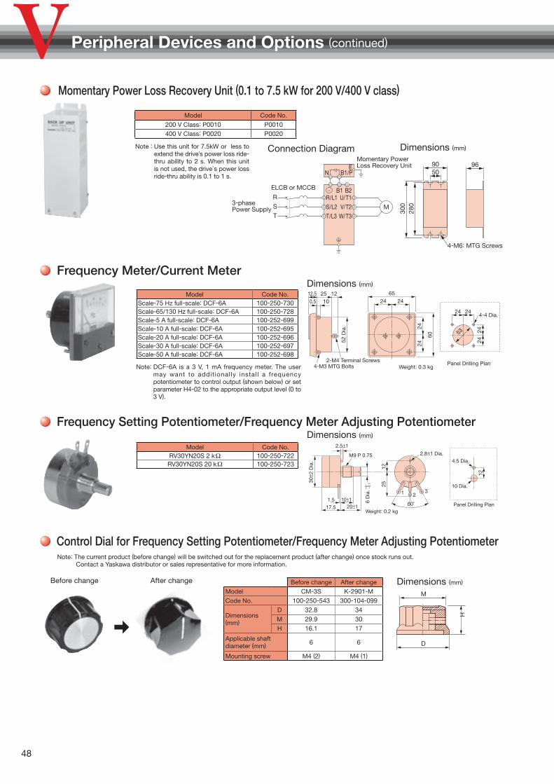
48
Frequency Meter/Current MeterDimensions (mm)
Note: DCF-6A is a 3 V, 1 mA frequency meter. The user may want to additionally install a frequency potentiometer to control output (shown below) or set parameter H4-02 to the appropriate output level (0 to 3 V).
Weight: 0.3 kgPanel Drilling Plan
52 D
ia. 24
24
2424
2424
60
2424122512.5
0.5 10
65
53
4-4 Dia.
2-M4 Terminal Screws4-M3 MTG Bolts
Model Code No.Scale-75 Hz full-scale: DCF-6A 100-250-730Scale-65/130 Hz full-scale: DCF-6A 100-250-728Scale-5 A full-scale: DCF-6A 100-252-699Scale-10 A full-scale: DCF-6A 100-252-695Scale-20 A full-scale: DCF-6A 100-252-696Scale-30 A full-scale: DCF-6A 100-252-697Scale-50 A full-scale: DCF-6A 100-252-698
Frequency Setting Potentiometer/Frequency Meter Adjusting PotentiometerDimensions (mm)
Control Dial for Frequency Setting Potentiometer/Frequency Meter Adjusting Potentiometer
Model Code No.RV30YN20S 2 kΩ 100-250-722
RV30YN20S 20 kΩ 100-250-723
Panel Drilling Plan
1 2
60˚
3
10±120±1
30± 2
Dia
.
M9 P 0.75
12
1225
6 D
ia.
17.51.5
Weight: 0.2 kg
10 Dia.
4.5 Dia.
2.8±1 Dia.
2.5±1
+ 0 − 0.1
Model Code No.
200 V Class: P0010 P0010400 V Class: P0020 P0020
M
R
S
T
R/L1S/L2T/L3
U/T1
B1/P
V/T2W/T3
E
ELCB or MCCB
Momentary Power Loss Recovery Unit
3-phase Power Supply
N96
5090
4-M6: MTG Screws
B2B1−
300
280
Connection Diagram Dimensions (mm)
Momentary Power Loss Recovery Unit (0.1 to 7.5 kW for 200 V/400 V class)
Note : Use this unit for 7.5kW or less to extend the drive’s power loss ride-thru ability to 2 s. When this unit is not used, the drive’s power loss ride-thru ability is 0.1 to 1 s.
Peripheral Devices and Options (continued)
Before change After change Before change After change
Model CM-3S K-2901-MCode No. 100-250-543 300-104-099
Dimensions (mm)
D 32.8 34M 29.9 30H 16.1 17
Applicable shaft diameter (mm) 6 6
Mounting screw M4 (2) M4 (1)
Dimensions (mm)
M
H
D
Note: The current product (before change) will be switched out for the replacement product (after change) once stock runs out. Contact a Yaskawa distributor or sales representative for more information.

49
Meter Plate for Frequency Setting Potentiometer/Frequency Meter Adjusting PotentiometerDimensions (mm)
Model Code No.
NPJT41561-1 100-250-701
0
1
3
4 6
7
9
10
45
45
12
3.6 Dia.9.5 Dia.
Output Voltage Meter
Model Code No.
Scale-300 V full-scale (Rectification Type Class 2.5) : SCF-12NH
VM000481
Scale-600 V full-scale (Rectification Type Class 2.5) : SCF-12NH
VM000502
Weight: 0.3 kgPanel Drilling Plan
85 D
ia.
4535
4535
5050
100
5050123012.5
0.5 10
120
87
4-5 Dia.
2-M4 Terminal Screws4-M3 MTG Bolts
Dimensions (mm)
*: For use with a standard voltage regulator. A standard voltage regulator may not match the drive
output voltage. Select a regulator specifically designed for the drive output (100-011-486), or a voltmeter that does not use a transformer and offers direct read out. P
erip
hera
l Dev
ices
and
Op
tions
Weight: 2.2 kg
Insulation capRed : Drive inputBlue: Drive output
4-M6 MTG holes 102±2
31 9086±256±1
Nameplate10
1±2
76± 2
1.6
GroundTerminal
Terminal block with cover(M3 screw)
U V u v E
approx. 85
Model Code No.
600 V meter for voltage transformerUPN-B 440/110 V (400/100 V) 100-011-486
Potential TransformerDimensions (mm)

50
Application Notes
Application NotesSelection■ Installing a Reactor
An AC or DC reactor can be used for the following:
・ to suppress harmonic current.
・ to smooth peak current that results from capacitor
switching.
・ when the power supply is above 600 kVA.
・ Use an AC reactor when also connecting a thyristor
converter to the same power supply system, regardless
of the conditions of the power supply.
■ Drive Capacity
Make sure that the motor’s rated current is less than the
drive’s output current. When running a specialized motor
or more than one motor in parallel from a single drive,
the capacity of the drive should be larger than 1.1 times
of the total motor rated current.
■ Starting Torque
The overload rating for the drive determines the starting
and accelerating characteristics of the motor. Expect
lower torque than when running from line power. To get
more starting torque, use a larger drive or increase both
the motor and drive capacity.
■ Emergency Stop
When the drive faults out, a protective circuit is activated
and drive output is shut off. This, however, does not stop
the motor immediately. Some type of mechanical brake
may be needed if it is necessary to halt the motor faster
than the Fast Stop function is able to.
■ Options
She B1, B2, − , +1, and +2 terminals are used to connect
optional devices. Connect only V1000-compatible devices.
■ Repetitive Starting/Stopping
Cranes (Hoists), elevators, punching presses, and other
such applications with frequent starts and stops often
exceed 150% of their rated current values. Heat stress
generated from repetitive high current can shorten the
lifespan of the IGBTs. The expected lifespan for the
IGBTs is about 8 million start and stop cycles with a 4
kHz carrier frequency and a 150% peak current.
Yaskawa recommends lowering the carrier frequency,
particularly when audible noise is not a concern. The
user can also choose to reduce the load, increase the
acceleration and deceleration times, or switch to a larger
drive. This will help keep peak current levels under 150%.
Be sure to check the peak current levels when starting and
stopping repeatedly during the initial test run, and make
adjustments accordingly.
For crane-type applications taking the inching function in
which the motor is quickly started and stopped, Yaskawa
recommends the following to ensure motor torque levels
and lower the drive:
Select a large enough drive so that peak current levels
remain below 150%.
The drive should be one frame size larger than the motor.
Installation■ Enclosure Panels
Keep the drive in a clean environment by either selecting an
area free of airborne dust, lint, oil mist, corrosive gas, and
flammable gas, or install the drive in an enclosure panel.
Leave the required space between the drives to provide for
cooling, and take steps to ensure that the ambient
temperature remains within allowable limits. Keep
flammable materials away from the drive. If the drive must
be used in an area where it is subjected to oil mist and
excessive vibration, protective designs are available.
Contact Yaskawa for details.
■ Installation Direction
The drive should be installed upright as specified in the manual.
4000
600
0 60 400Drive Capacity (kVA)
Pow
er S
upp
ly
Cap
acity
( kVA
) Reactor required
Reactorunnecessary

51
■ Installation of Bypass Circuit
If the fuse blows or the circuit breaker (MCCB) trips,
check the cable wiring and selection of peripheral
devices and identify the cause. If the cause cannot be
identified, do not turn ON the power supply or operate
the device. Contact your Yaskawa representative.
If a drive fails and the motor will be directly driven using
a commercial power supply, install the bypass circuit
shown in the diagram below. If this bypass circuit is not
installed, remove the drive and then connect the motor
to a commercial power supply. (In other words, after
disconnecting the cables connected to the main circuit
terminals, such as main circuit power supply input
terminals R/L1, S/L2, and T/L3 and drive output
terminals U/T1, V/T2, and W/T3, connect the motor to a
commercial power supply.)
ELCB (MCCB)
Three-phasePower Supply200-400 V50/60 Hz
MC3 Motor
Drive
R/L1S/L2S
R
T T/L3
MC2
MC1
U/T1V/T2
W/T3
UVW
M
If a drive fails and the motor will be directly driven using a commercial power supply, set up a sequence where MC3 and MC2 are rst turned OFF, and then MC1 is turned ON.
Settings■ If using Open Loop Vector Control designed for
permanent magnet motors, make sure that the proper
motor code has been set to parameter E5-01 before
performing a trial run.
■ Upper Limits
Because the drive is capable of running the motor
at up to 400 Hz, be sure to set the upper limit for the
frequency to control the maximum speed. The default
setting for the maximum output frequency is 60 Hz.
■ DC Injection Braking
Motor overheat can result if there is too much current
used during DC Injection Braking, or if the time for DC
Injection Braking is too long.
■ Acceleration/Deceleration Times
Acceleration and deceleration times are affected by
how much torque the motor generates, the load torque,
and the inertia moment (GD2/4). Set a longer accel/de-
cel time when Stall Prevention is enabled. The accel/
decel times are lengthened for as long as the Stall Pre-
vention function is operating. For faster acceleration
and deceleration, increase the capacity of the drive.
Compliance with Harmonic Suppression Guidelines
V1000 conforms to strict guidelines in Japan covering har-
monic suppression for power conversion devices. Defined
in JEM-TR201 and JEM-TR226 and published by the Ja-
pan Electrical Manufacturers' Association, these guide-
lines define the amount of harmonic current output accept-
able for new installation. Contact your YASKAWA
representative.
General Handling■ Wiring Check
Never short the drive output terminals or apply voltage to
output terminals (U/T1, V/T2, W/T3), as this can cause
serious damage to the drive. Doing so will destroy the
drive. Be sure to perform a final check of all sequence
wiring and other connections before turning the power
on. Make sure there are no short circuits on the control
terminals (+V, AC, etc.), as this could damage the drive.
■ Magnetic Contactor Installation
Avoid switching a magnetic contactor on the power
supply side more frequently than once every 30 minutes.
Frequent switching can cause damage to the drive.
■ Inspection and Maintenance
After shutting off the drive, make sure the CHARGE
light has gone out completely before preforming any
inspection or maintenance. Residual voltage in drive
capacitors can cause serious electric shock.
The heatsink can become quite hot during operation,
and proper precautions should be taken to prevent
burns. When replacing the cooling fan, shut off the
power and wait at least 15 minutes to be sure that the
heatsink has cooled down.
■ Transporting the Drive
Never steam clean the drive.
During transport, keep the drive from coming into
contact with salts, fluorine, bromine and other such
harmful chemicals.
Ap
plic
atio
n N
otes

52
Application Notes (continued)
Peripheral Devices■ Installing a Ground Fault Interrupter or an MCCB
Install an MCCB or a ground fault interrupter recom-
mended by Yaskawa to the power supply side of the
drive to protect internal circuitry. The type of MCCB
needed depends on the power supply power factor (power supply voltage, output frequency, load character-
istics, etc.). Sometimes a fairly large MCCB may be re-
quired due to the affects of harmonic current on operat-
ing characteristics. Those using a ground fault interrupter
other than those recommended in this catalog, use one
fitted for harmonic suppression measures (one designed
specifically for drives). The rated current of the ground
fault interrupter must be 200 mA or higher per drive unit.
Select an MCCB with a rated capacity greater than the
short-circuit current for the power supply. For a fairly
large power supply transformer, a fuse can be added to
the ground fault interrupter or MCCB in order to handle
the short-circuit current level.
■ Magnetic Contactor for Input Power
Use a magnetic contactor (MC) to ensure that power
to the dr ive can be complete ly shut of f when
necessary.
The MC should be wired so that it opens when a fault
output terminal is triggered.
Even though an MC is designed to switch following a
momentary power loss, frequent MC use can damage
other components. Avoid switching the MC more than
once every 30 minutes. The MC will not be activated
after a momentary power loss if using the operator
keypad to run the drive. This is because the drive is
unable to restart automatically when set for LOCAL.
Although the drive can be stopped by using an MC
installed on the power supply side, the drive cannot
stop the motor in a controlled fashion, and it will
simply coast to stop. If a braking resistor or dynamic
braking unit has been installed, be absolutely sure to
set up a sequence that opens the MC with a thermal
protector switch connected to the braking resistor
device.
■ Magnetic Contactor for Motor
As a general principle, the user should avoid opening
and closing the magnetic contactor between the motor
and the drive during run. Doing so can cause high peak
currents and overcurrent faults. If magnetic contactors
are used to bypass the drive by connecting the motor to
the power supply directly, make sure to close the bypass
only after the drive is stopped and fully disconnected
from the motor. The Speed Search function can be used
to start a coasting motor.
Use an MC with delayed release if momentary power
loss is a concern.
■ Motor Thermal Over Load Relay Installation
Although the drive comes with built in electrothermal
protection to prevent damage from overheat, a thermal
relay should be connected between the drive and each
motor if running several motors from the same drive. For a
multipole motor or some other type of non-standard motor,
Yaskawa recommends using an external thermal relay
appropriate for the motor. Be sure to disable the motor
protection selection parameter (L1-01 = 0), and set the
thermal relay or thermal protection value to 1.1 times the
motor rated current listed on the motor nameplate.
When a high carrier frequency and long motor cables
are used, nuisance tripping of the thermal relay may
occur due to increased leakage current. To avoid this,
reduce the carrier frequency or increase the tripping
level of the thermal overload relay.
■ Improving the Power Factor
Installing a DC or AC reactor to the input side of the
drive can help improve the power factor.
Refrain from using a capacitor or surge absorber on the
output side as a way of improving the power factor,
because high-frequency contents on the output side
can lead to damage from overheat. This can also lead to
problems with overcurrent.
■ Radio Frequency Interference
Drive output contains high-frequency contents that can
affect the performance of surrounding electronic
instruments such as an AM radio. These problems can
be prevented by installing a noise filter, as well as by
using a properly grounded metal conduit to separate
wiring between the drive and motor.

53
Ap
plic
atio
n N
otes
■ Wire Gauges and Wiring Distance
Motor torque can suffer as a result of voltage loss across
a long cable running between the drive and motor,
especially when there is low frequency output. Make
sure that a large enough wire gauge is used.
The optional LCD operator requires a proprietary cable
to connect to the drive. If an analog signal is used to
operate the drive via the input terminals, make sure that
the wire between the analog operator and the drive is no
longer than 50 m, and that it is properly separated from
the main circuit wiring. Use reinforced circuitry (main
circuit and relay sequence circuitry) to prevent
inductance from surrounding devices. To run the drive
with a frequency potentiometer via the external terminals,
use twisted shielded pair cables and ground the shield.
Shield ground terminal
Pulse train input (max. 32 kHz)Pulse train input
Main frequency reference
Frequency Setting Potentiometer
RP
+V
A1
A2AC
2 kΩ Setting power supply +10.5 V max. 20 mAMain frequency reference 0 to 10 V (20 kΩ)Multi-function analog input 0 to 10 V (20 kΩ) or 4 to 20 mA (250 Ω) / 0 to 20 mA (250 Ω)
■ Counteracting Noise
Because V1000 is designed with PWM control, a low
carrier frequency tends to create more motor flux noise
than using a higher carrier frequency. Keep the following
point in mind when considering how to reduce motor noise:
Lowering the carrier frequency (C6-02) minimizes the
effects of noise.
A line noise filter can be effective in reducing the affects
on AM radio frequencies and poor sensor performance.
See “Options and Peripheral Devices” on page 28.
Make sure the distance between signal and power
lines is at least 10 cm (up to 30 cm is preferable), and
use twisted pair cable to prevent induction noise form
the drive power lines.
Keep signal lines and power lines at least 30 cm apart
noise �lter
power supply
sensor power supply
Connect shielded line to a neutral line (not to ground)
M
Use twisted shielded pair cable
noise �lter
V1000
+sensor
<Provided by JEMA>
Connect a 0.1 F capacitorμ
−
■ Leakage Current
High-frequency leakage current passes through stray
capacitance that exists between the power lines to the
drive, ground, and the motor lines. Consider using the
following peripheral devices to prevent problems with
leakage current.
Problem Solution
Ground Leakage Current
MCCB is mistakenly triggered
Lower the carrier frequency set to parameter C6-02.
Try using a component designed to minimize harmonic distortion for the MCCB such as the NV series by Mitsubishi.
Current Leakage Between
Lines
Thermal relay connected to the external terminals is mistakenly triggered by harmonics in the leakage current
Lower the carrier frequency set to parameter C6-02.
Use the drive’s built-in thermal motor protection function.
The following table shows the guidelines for the set
value of the carrier frequency relative to the wiring
distance between the drive and the motor when using
V/f control.
When Open Loop Vector Control or PM Open Loop
Vector Control is used and the wiring distance is 50 m
to 100 m, set the carrier frequency to 2 kHz.
Wiring Distance* 50 m or less 100 m or less Greater than 100 m
C6-02:Carrier Frequency Selection
1 to Auto(15 kHz or less)
1, 2, 7 to Auto(5 kHz or less)
1, 7 to Auto(2 kHz or less)
*: When a single drive is used to run multiple motors, the length of the motor cable should be calculated as the total distance between the drive and each motor.
When the wiring distance exceeds 100 m, use the drive
observing the following conditions.
Select V/f control mode (A1-02=0)
To start a coasting motor
a) Use the current detection type (b3-24=0) when
using the speed search function, or
b) Set the DC injection braking time at start (b2-03=0.01
to 10.00 sec) to stop a coasting motor and restart it.
More than one synchronous motor cannot be connected
to a single drive. The maximum wiring distance between
the drive and the synchronous motor must be 100 m.

54
Application Notes (continued)
Notes on Motor Operation
■ Motor Bearing Life
In applications involving constant speed over long
periods, such as fans, pumps, extruders, and textile
machinery, the l ife of the motor bearing may be
shortened. This is called bearing electrolytic corrosion.
The installation of a zero-phase reactor between the
drive and motor, and the utilization of a motor with
insulated bearings are effective countermeasures.
Details can be found in the technical documentation.
Contact your Yaskawa or nearest sales representative
for more information.
Using a Standard Motor■ Low Speed Range
There is a greater amount
of loss when operating a
motor using an drive than
when running directly from
line power. With a drive,
the motor can become
quite hot due to the poor
ability to cool the motor
at low speeds. The load
torque should be reduced accordingly at low speeds. The
figure above shows the allowable load characteristics for
a Yaskawa standard motor. A motor designed specifically
for operation with a drive should be used when 100%
continuous torque is needed at low speeds.
■ Insulation Tolerance
Consider voltage tolerance levels and insulation in
applications with an input voltage of over 440 V or
particularly long wiring distances.
■ High Speed Operation
Problems may occur with the motor bearings and
dynamic balance in applications operating at over 60
Hz. Contact Yaskawa for consultation.
■ Torque Characteristics
Torque characteristics differ when operating directly from
line power. The user should have a full understanding of
the load torque characteristics for the application.
■ Vibration and Shock
V1000 lets the user choose between high carrier PWM
control and low carrier PWM. Selecting high carrier
PWM can help reduce motor oscillation. Keep the
following points in mind when using high carrier PWM:
(1) Resonance
Take particular caution when using a variable speed
drive for an application that is conventionally run from
line power at a constant speed. Shock-absorbing
rubber should be installed around the base of the
motor and the Jump Frequency selection should be
enabled to prevent resonance.(2) Any imperfection on a rotating body increases
vibration with speed
Caution should be taken when operating above the
motor rated speed.
■ Audible Noise
Noise created during run varies by the carrier frequency
setting. Using a high carrier frequency creates about as
much noise as running from line power. Operating above
the rated r/min (i.e., above 60 Hz), however, can create
unpleasant motor noise.
50
3 6 20 60
60708090
100
25% ED (or 15 min)
40% ED (or 20 min)
60% ED (or 40 min)
Allowable Load Characteristics for a Yaskawa Motor
Frequency (Hz)
Continuous operation
Torq
ue ( %
)

55
Using a Synchronous Motor■ Please contact us for consultation when using a
synchronous motor not already approved by Yaskawa.
■ Even when the power has been shut off for a drive run-
ning a PM motor, voltage continues to be generated at the
motor terminals while the motor coasts to stop. Take the
precautions described below to prevent shock and injury:
Applications where the machine can still rotate even
though the drive has fully stopped should have a low
voltage manual load switch installed to the output side
of the drive. (Yaskawa recommends the AICUT LB
Series by AICHI Electric Works Co., Ltd.)
Do not apply to a load that could potentially rotate the
motor faster than the maximum allowable r/min even
when the drive has been shut off.
Wait at least one minute after opening the low
voltage manual load switch on the output side before
inspecting the drive or performing and maintenance.
Do not open a close the low voltage manual load
switch while the motor is running, as this can damage
the drive.
To close the low voltage manual load switch connected
to a coasting motor, first turn on the power to the drive
and make sure that the drive has stopped.
■ Synchronous motors cannot be started directly from
line power. Applications that requiring line power to
start should use an induction motor with the drive.
■ A single drive is not capable of running multiple
synchronous motors at the same time. Use a standard
induction motor for such setups.
■ At start, a synchronous motor may rotate slightly in the
opposite direction of the Run command depending on
parameter settings and motor type.
■ Uses derated torque of 50% less than starting torque.
Set up the motor with the drive after verifying the
starting torque, allowable load characteristics, impact
load tolerance, and speed control range.
■ Even with a braking resistor, braking torque is less than
125% when running between 20% to 100% speed, and
falls to less than half the braking torque when running
at less than 20% speed.
■ There is no torque control available, and torque limits
cannot be set. Consequently, synchronous motors are
not appropriate for applications that operate at low
speeds (less than 10% of the rated speed) or experience
sudden changes in speed. Such applications are better
suited for induction motors or servo drives.
■ The allowable load inertia moment is 50 times less than
the motor inertia moment. Contact Yaskawa concerning
applications with a larger inertia moment.
■ When using a holding brake, release the brake prior to
starting the motor. Failure to set the proper timing can
result in speed loss. Not for use with conveyor,
transport, or hoist type applications.
■ To restart a coasting motor rotating at over 120 Hz, use
the Short Circuit Braking* function to first bring the
motor to a stop. Short Circuit Braking requires a special
braking resistor.
Speed Search can be used to restart a coasting motor
rotating slower than 120 Hz. If the motor cable is
relatively long, however, the motor should instead be
stopped using Short Circuit Braking and then restarted.
*: Short Circuit Braking creates a short-circuit in the motor windings to forcibly stop a coasting motor.
Ap
plic
atio
n N
otes

56
Application Notes (continued)
Applications with Specialized Motors
■ Multi-pole Motor
Because the rated current will differ from a standard
motor, be sure to check the maximum current when
selecting a drive. Always stop the motor before switching
between the number of motor poles. If a regenerative
overvoltage fault occurs or if overcurrent protection is
triggered, the motor will coast to stop.
■ Submersible Motor
Because motor rated current is greater than a standard
motor, select the drive capacity accordingly. Be sure to
use a large enough motor cable to avoid decreasing the
maximum torque level on account of voltage drop
caused by a long motor cable.
■ Explosion-proof Motor
Both the motor and drive need to be tested together to
be certified as explosion-proof. The drive is not for
explosion proof areas.
■ Geared Motor
Continuous operation specifications dif fer by the
manufacturer of the lubricant. Due to potential problems
of gear damage when operating at low speeds, be
sure to select the proper lubricant. Consult with the
manufacturer for applications that require speeds greater
than the rated speed range of the motor or gear box.
■ Single-phase Motor
Variable speed drives are not designed for operating
single phase motors. Using a capacitor to start the
motor causes high-frequency current to flow into the
capacitors, potentially causing damage. A split-phase
start or a repulsion start can end up burning out the
starter coils because the internal centrifugal switch is
not activated. V1000 is for use only with 3-phase motors.
■ Uras Vibrator
Uras vibrator is a vibration motor that gets power from
centrifugal force by rotating unbalanced weights on both
ends of the shaft. Make the following considerations
when selecting a drive for use with an Uras vibrator:
(1) Uras vibrator should be used within the drive rated
frequency(2) Use V/f Control(3) Increase the acceleration time five to fifteen times
longer than would normally be used due to the high
amount of load inertia of an Uras vibratorNote: A drive with a different capacity must be selected if the
acceleration time is less than 5 s.
(4) Drive may have trouble starting due to undertorque that
results from erratic torque (static friction torque at start)
■ Motor with Brake
Caution should be taken when using a drive to operate a
motor with a built-in holding brake. If the brake is
connected to the output side of the drive, it may not
release at start due to low voltage levels. A separate
power supply should be installed for the motor brake.
Motors with a built-in brake tend to generate a fair
amount of noise when running at low speeds.
Power Driven Machinery (decelerators, belts, chains, etc.)Continuous operation at low speeds wears on the lubricating
material used in gear box type systems to accelerate and
decelerate power driven machinery. Caution should also be
taken when operating at speeds above the rated machine
speed due to noise and shortened performance life.

57
YASKAWA AC Drive Series
Name FeatureCapacity Range (kW)
Outline
Gen
eral
Pur
pos
e
J1000Compact
V/f Control
AC Drive
Three-Phase
200 V Class0.1 5.5
Ultra-small body enables side-by-side installation. Compact design of enclosure panel Easy operation with the Potentiometer Option Unit The noise-suppressing Swing PWM system reduces harsh sound. The full-range fully-automatic torque boost function provides high torque output.
(100%/1.5 Hz,150%/3 Hz) The Stall Prevention function and the momentary power loss ride-thru ensure continuous
operation, regardless of load/power supply fluctuations or momentary power loss. The Overexcitation braking function enables rapid braking, without using a braking
resistor.
Single-Phase
200 V Class0.1 2.2
Three-Phase
400 V Class 0.2 5.5
V1000Compact Vector
Control AC Drive
Three-Phase
200 V Class0.1 18.5 Small body and high performance (Current vector control)
For both induction motors and synchronous motors (IPMM/SPMM) High starting torque: 200%/0.5 Hz*
Torque limit function * At Heavy Duty rating, for induction motors with 3.7 kW or lower Application-specific function selection for simplified optimum setup Easy maintenance using the detachable terminal block with the
parameter backup function
Single-Phase
200 V Class0.1 3.7
Three-Phase
400 V Class 0.2 18.5
A1000Advanced Vector
Control AC Drive
Three-Phase
200 V Class 0.4 110
For both induction motors and synchronous motors (IPMM/SPMM) High starting torque IPM motor without a motor encoder: 0 r/min
200% torque Application preset function selection for simplified optimum setup Easy maintenance using the detachable terminal block with the
parameter backup function
Three-Phase
400 V Class 0.4 630
Varispeed G7
General-purpose
Inverter With
Advanced
Vector Control
Minimal Noise
Three-Phase
200 V Class 0.4 110
The 400 V class uses 3-level control for a more perfect output waveform. Open Loop Vector control ensures 150% or higher torque during
operation at 0.3 Hz. Flux Vector Control provides a high torque of 150% at zero speed.
Easy maintenance and inspection using the detachable control circuit terminals and the detachable cooling fan.
Software for various applications (for crane, hoist, etc.) The Auto-Tuning function upgrades all types of general motors to be
compatible with high-performance drives.
Three-Phase
400 V Class 0.4 300
U1000Low Harmonics
Regenerative
Matrix Converter
Three-Phase
200 V Class 5.5 55*
Drastically reduced power supply harmonics and improved harmonics environment.
Power regeneration function with even greater energy efficiency. All-in-one design accomplished reduced wiring and saving space. Motor drive state-of-the-art technology, induction motor and, of course, synchronous motor drive are also possible.
Commercial power supply can be switched without peripheral phase detectors and contactors.
The visual programming function DriveWorksEZ is installed as standard, easily customized, and can be freely used on a PC.
Three-Phase
400 V Class 2.2 500*
ECOiPM Drive
Compact and
Energy
Efficiency Drives
Three-Phase
200 V Class 0.4 15
Grade higher than IE3 efficiency class saves energy during operation. V1000 drives combined with compact ECOiPM motors make more
compact and lighter drive systems. Less maintenance because bearing grease life is approx. three times
longer compared to use with induction motors. Improved reliability with elimination of an encoder of precision device.
Three-Phase
400 V Class 0.4 15
V1000pico
Drive
Super Compact
and Environmentally
Drives
Three-Phase
200 V Class0.1 0.75
V1000 drives combined with super compact V1000pico motors make more compact and lighter drive systems.
Applicable in locations subject to water jets or abrasive powder with its protective enclosure rated IP65 or higher.
Improved reliability with elimination of an encoder of precision device. Use of V1000 drives, which can control not only induction motors but
also synchronous motors, brings the uniformity of your stock.
Sp
ecia
l Use
L1000AElevator
Applications
Three-Phase
200 V Class 1.5 110
Cutting-edge drive technology allows L1000A to run a newly installed gearless synchronous motor, or a refurbished geared induction motor. This minimizes equipment required for your application.
Interfaces to match gearless, synchronous motors and every type of absolute encoder.
Even without a load sensor, high-performance torque compensation and high-resolution absolute encoder eliminate rollback when the brake is released.
Output interrupt Satisfies safety requirements and Ensures a reliable elevator system.
Rescue Operation switches to backup battery or UPS in case of a power outage.
All standard models are compliant with the Europe’s RoHS directive.
Three-Phase
400 V Class 1.5 110
*: Units are displayed in kW. When selecting a model, make sure that the rated output current is higher than the motor rating current.
0.1 1 10 100 300 630
Ap
plic
atio
n N
otes
/ Y
AS
KA
WA
AC
Driv
e S
erie
s

58
Warranty
Warranty Information■ Warranty Period The period is 12 months from the date the product is first used by the buyer, or 18 months from the date of
shipment, whichever occurs first.
■ Post-Warranty Repair Period The post-warranty repair period applies to products that are not in the standard warranty period.
During the post-warranty repair period, Yaskawa will repair or replace damaged parts for a fee. There is a limit to the period during which Yaskawa will repair or replace damaged parts. Contact Yaskawa or your nearest sales representative for more information.
■ Warranty Scope Failure diagnosis The primary failure diagnosis shall be performed by your company as a rule.
By your company's request, however, we or our service sector can execute the work for your company for pay. In such a case, if the cause of the failure is in our side, the work is free.
Repair When a failure occurred, repairs, replacement, and trip to the site for repairing the product shall be free of charge.
However, the following cases have to be paid. ・ Cases of failure caused by inappropriate storing, handling, careless negligence, or system design errors performed
by you or your customers. ・ Cases of failure caused by a modification performed by your company without our approval. ・Cases of failure caused by using the product beyond the specification range. ・Cases of failure caused by force majeure such as natural disaster and fire. ・Cases in which the warranty period has expired. ・Cases of replacement of consumables and other parts with limited service life. ・Cases of product defects caused by packaging or fumigation processing. ・Cases of malfunction or errors caused by programs created by you using DriveWorksEZ. ・Other failures caused by reasons for which Yaskawa is not liable.
The services described above are available in Japan only. Please understand that failure diagnosis is not available outside of Japan. If overseas after-sales service is desired, consider registering for the optional overseas after-sales service contract.
Exception of Guaranteed Duty Lost business opportunities and damage to your property, including your customers and other compensation for
work, is not covered by the warranty regardless of warranty eligibility, except when caused by product failure of Yaskawa products.
■ Definition of Delivery For standard products that are not set or adjusted for a specified application, Yaskawa considers the product
delivered when it arrives at your company and Yaskawa is not responsible for on-site adjustments or test runs.

59
Global Service Network
ChicagoSan Francisco
Boston
Frankfurt
Bengaluru
Singapore
Bangkok
Seoul
Shanghai
Taipei
North Carolina
Mexico City
Bogota
Sao Paulo
New Jersey
Los Angeles
1
4
3
58
10
11
14
17
1312
Tokyo
6 7
9
2Hanoi
Ho Chi Minh
16
Ohio
Jakarta
15
War
rant
y /
Glo
bal
Ser
vice
Net
wor
k
Region Service Area Service Location Service Agency Telephone/Fax
North America
U.S.A.
Chicago (HQ)Los Angeles
San FranciscoNew Jersey
BostonOhio
North Carolina
●1 YASKAWA AMERICA INC.Headquarters☎ +1-847-887-7000FAX +1-847-887-7370
Mexico Mexico City ●2 PILLAR MEXICANA. S.A. DE C.V.☎ +52-555-660-5553FAX +52-555-651-5573
South America
Brazil Sao Paulo ●3 YASKAWA ELÉTRICO DO BRASIL LTDA.☎ +55-11-3585-1100FAX +55-11-3585-1187
Colombia Bogota ●4 VARIADORES LTD.A. ☎ +57-1-795-8250
EuropeEurope,
South AfricaFrankfurt ●5 YASKAWA EUROPE GmbH
☎ +49-6196-569-300FAX +49-6196-569-398
Asia
JapanTokyo,
offices nationwide
●6 YASKAWA ELECTRIC CORPORATION (Manufacturing, sales)
☎ +81-3-5402-4502FAX +81-3-5402-4580
●7 YASKAWA ELECTRIC ENGINEERING CORPORATION (After-sales service)
☎ +81-4-2931-1810FAX +81-4-2931-1811
South Korea Seoul
●8 YASKAWA ELECTRIC KOREA CORPORATION (Sales)
☎ +82-2-784-7844FAX +82-2-784-8495
●9 YASKAWA ENGINEERING KOREA CORPORATION (After-sales service)
☎ +82-2-3775-0337FAX +82-2-3775-0338
ChinaBeijing, Guangzhou,
Shanghai●10 YASKAWA ELECTRIC (CHINA) CO., LTD.
☎ +86-21-5385-2200FAX +86-21-5385-3299
Taiwan Taipei ●11 YASKAWA ELECTRIC TAIWAN CORPORATION☎ +886-2-8913-1333FAX +886-2-8913-1513
Singapore Singapore
●12 YASKAWA ASIA PACIFIC PTE.LTD. (Sales)
☎ +65-6282-3003FAX +65-6289-3003
●13 YASKAWA ASIA PACIFIC PTE. LTD. (After-sales service)
☎ +65-6282-1601FAX +65-6282-3668
Thailand Bangkok ●14 YASKAWA ELECTRIC(THAILAND)CO., LTD.☎ +66-2-017-0099FAX +66-2-017-0090
VietnamHo Chi Minh
●15 YASKAWA ELECTRIC VIETNAM CO., LTD.
☎ +84-8-3822-8680FAX +84-8-3822-8780
Hanoi☎ +84-4-3634-3953FAX +84-4-3654-3954
India Bengaluru ●16 YASKAWA INDIA PRIVATE LIMITED☎ +91-80-4244-1900FAX +91-80-4244-1901
Indonesia Jakarta ●17 PT. YASKAWA ELECTRIC INDONESIA☎ +62-21-2982-6470FAX +62-21-2982-6471
OceaniaAustralia
New ZealandContact to service agency in Singapore (●12 ●13 ).

DRIVE CENTER (INVERTER PLANT)2-13-1, Nishimiyaichi, Yukuhashi, Fukuoka, 824-8511, JapanPhone +81-930-25-2548 Fax +81-930-25-3431http://www.yaskawa.co.jp
YASKAWA ELECTRIC CORPORATIONNew Pier Takeshiba South Tower, 1-16-1, Kaigan, Minatoku, Tokyo, 105-6891, JapanPhone +81-3-5402-4502 Fax +81-3-5402-4580http://www.yaskawa.co.jp
YASKAWA AMERICA, INC.2121, Norman Drive South, Waukegan, IL 60085, U.S.A.Phone +1-800-YASKAWA (927-5292) or +1-847-887-7000 Fax +1-847-887-7310http://www.yaskawa.com
YASKAWA ELÉTRICO DO BRASIL LTDA.777, Avenida Piraporinha, Diadema, São Paulo, 09950-000, BrasilPhone +55-11-3585-1100 Fax +55-11-3585-1187http://www.yaskawa.com.br
YASKAWA EUROPE GmbHHauptstraβe 185, 65760 Eschborn, GermanyPhone +49-6196-569-300 Fax +49-6196-569-398http://www.yaskawa.eu.com E-mail: [email protected]
YASKAWA ELECTRIC KOREA CORPORATION35F, Three IFC, 10 Gukjegeumyung-ro, Yeongdeungpo-gu, Seoul, 07326, KoreaPhone +82-2-784-7844 Fax +82-2-784-8495http://www.yaskawa.co.kr
YASKAWA ASIA PACIFIC PTE. LTD.30A Kallang Place, #06-01 Singapore 339213Phone +65-6282-3003 Fax +65-6289-3003http://www.yaskawa.com.sg
YASKAWA ELECTRIC (THAILAND) CO., LTD.59, 1st-5th Floor, Flourish Building, Soi Ratchadapisek 18, Ratchadapisek Road, Huaykwang, Bangkok 10310, ThailandPhone +66-2-017-0099 Fax +66-2-017-0799http://www.yaskawa.co.th
PT. YASKAWA ELECTRIC INDONESIASecure Building-Gedung B Lantai Dasar & Lantai 1 Jl. Raya Protokol Halim Perdanakusuma, Jakarta 13610, IndonesiaPhone +62-21-2982-6470 Fax +62-21-2982-6471http://www.yaskawa.co.id/
YASKAWA ELETRIC VIETNAM CO., LTD HO CHI MINH OFFICESuite 1904A, 19th Floor Centec Tower, 72-74 Nguyen Thi Minh Khai Street, Ward 6, District 3, Ho Chi Minh City, VietnamPhone +84-8-3822-8680 Fax +84-8-3822-8780
YASKAWA ELETRIC VIETNAM CO., LTD HA NOI OFFICE2nd Floor, Somerset Hoa Binh Hanoi, No. 106, Hoang Quoc Viet Street, Cau Giay District, Hanoi, VietnamPhone +84-4-3634-3953 Fax +84-4-3654-3954
YASKAWA ELECTRIC (CHINA) CO., LTD.22F, Link Square 1, No.222, Hubin Road, Shanghai, 200021, ChinaPhone +86-21-5385-2200 Fax +86-21-5385-3299http://www.yaskawa.com.cn
YASKAWA ELECTRIC (CHINA) CO., LTD. BEIJING OFFICERoom 1011, Tower W3 Oriental Plaza, No.1 East Chang An Ave.,Dong Cheng District, Beijing, 100738, ChinaPhone +86-10-8518-4086 Fax +86-10-8518-4082
YASKAWA ELECTRIC TAIWAN CORPORATION12F, No. 207, Sec. 3, Beishin Rd., Shindian Dist., New Taipei City 23143, TaiwanPhone: +886-2-8913-1333 Fax: +886-2-8913-1513 or +886-2-8913-1519http://www.yaskawa.com.tw
YASKAWA INDIA PRIVATE LIMITED#17/A, 2nd Main, Electronic City, Phase-I, Hosur Road, Bengaluru 560 100, IndiaPhone +91-80-4244-1900 Fax +91-80-4244-1901http://www.yaskawaindia.in
LITERATURE NO. KAEP C710606 08I <8>-0
V1-01-19-06Published in Japan July 2019
In the event that the end user of this product is to be the military and said product is to be employed in any weapons systems or the manufacture thereof, the export will fall under the relevant regulations as stipulated in the Foreign Exchange and Foreign Trade Regulations. Therefore, be sure to follow all procedures and submit all relevant documentation according to any and all rules, regulations and laws that may apply.
Speci�cations are subject to change without notice for ongoing product modi�cations and improvements.
© 2007 YASKAWA ELECTRIC CORPORATION
Certi�ed forISO9001 andISO14001
JQA-EM0202JQA-QMA14913
V1000
advanced !Soeasy !So
small !So
200 V CLASS, THREE-PHASE INPUT: 0.1 to 18.5 kW200 V CLASS, SINGLE-PHASE INPUT: 0.1 to 3.7 kW400 V CLASS, THREE-PHASE INPUT: 0.2 to 18.5 kW
YASKAWA AC DriveCompact Vector Control Drive
V1000