A compact compliant actuator (CompAct™) with variable physical damping
7
Abstract —The new areas of technical exploitation of robotics systems has recently set new trends for the robotic actuation by demanding more versatile systems which can cope with unpredictable interactions within not well defined environments and work in close vicinity with the human. Following these trends, this work presents the development of a new actuation system with embodied characteristics such as passive compliance and variable physical damping. Compared to the other existing compliant linear or rotary actuators the proposed CompAct unit has the ability to regulate the oscillations induced by the introduction of the compliance by means of a variable physical damping actuator (VPDA) unit. Apart from facilitating the control the VPDA unit can assist in managing the energy transfer from/to the compliant module. The mechatronics, model and control scheme of the CompAct are analysed. The overall system is evaluated with experimental trials performed using a prototype unit. Preliminary results are presented to show that the unit and the proposed control scheme are capable of regulating the impedance components (stiffness and damping) within a wide range and with good fidelity. I. INTRODUCTION ntil recently, the use of stiff transmission systems combined with high gain PID controls has been the usual actuation approach employed in the robotic field. The resulted precision and repeatability of these systems made them suitable to operate in industrial environments within assembly lines for mass production where their workspace was confined within restricted areas. Although the non-backdrivability and the large stiffness of these industrial robots improve their precision the resulted large output mechanical impedance makes them inherently unsafe [1]. However, safety is not the only feature being compromised in these “stiff” actuated robots. Biological systems, for instance, store and release elastic potential Matteo Laffranchi is with the Italian Institute of Technology (IIT), Genova 16163, Italy (e-mail: [email protected]). Nikos G.Tsagarakis is with the Italian Institute of Technology (IIT), Genova 16163, Italy (phone: +39 010 71781 428; e-mail: [email protected]). Darwin G.Caldwell is with the Italian Institute of Technology (IIT), Genova 16163, Italy ( e-mail: [email protected]). energy into/from muscles and tendons during normal daily activities such as walking, running, jumping, etc [2-4]. The management of the elastic potential energy stored into these biological structures is essential for reducing the energy consumption and for achieving mechanical power peaks which could not be obtained using a stiff structure. These limitations motivated the robotic community to explore and attempt to replicate these biological properties into robotic structures, obtaining benefits in terms of performance, safety and energy efficiency [5-6]. As a result of this several compliant actuator prototypes have been introduced [5, 7- 11]. Despite the certain merits gained with the introduction of compliance, there are also some negative effect as the introduction of dynamics which can induce oscillations with a frequency that depend on the stiffness of the joint and the inertia of the link. To suppress these oscillations when the vibration modes of the compliant system are excited, damping is necessary. Humans, for instance, would not be able to position a limb quickly and accurately and damp the oscillation when an impulsive force is exerted on the limb without joint damping [12]. Hence, the introduction of damping can potentially bring several benefits in the compliant robots assisting their control and improving their accuracy. In general, damping can be embedded in a robotic system by means of active, passive or semi active solutions. The implementation of a purely passive system is the simplest solution, but may not be the appropriate from the robotic perspective since passive dampers provide a certain fixed amount of damping while a variable damping may be required to cope with variations of the system’s configuration and/or trajectory and load. Another drawback of the fixed passive solution is that the damping system cannot be disconnected and therefore energy is always dissipated. From the energy storage perspective this is a negative characteristic as it will reduce the amount of elastic potential energy stored or released to/from the compliant joint. Active damping solutions can provide variability on the exhibited virtual damping coefficient by means of impedance/admittance control, [13]. However, these solutions are ineffective for frequencies which are above the closed loop bandwidth of the controlled system and therefore not sufficient to compensate the high frequency oscillations caused, for instance, by a lightweight link and/or a relatively stiff joint. In addition, usually active control Matteo Laffranchi, Nikos Tsagarakis and D.G.Caldwell Italian Institute of Technology (IIT), Genova 16163, Italy A Compact Compliant Actuator (CompAct™) with Variable Physical Damping U 2011 IEEE International Conference on Robotics and Automation Shanghai International Conference Center May 9-13, 2011, Shanghai, China 978-1-61284-380-3/11/$26.00 ©2011 IEEE 4644
-
Upload
independent -
Category
Documents
-
view
1 -
download
0
Transcript of A compact compliant actuator (CompAct™) with variable physical damping

Abstract —The new areas of technical exploitation of robotics systems has recently set new trends for the robotic actuation by demanding more versatile systems which can cope with unpredictable interactions within not well defined environments and work in close vicinity with the human. Following these trends, this work presents the development of a new actuation system with embodied characteristics such as passive compliance and variable physical damping. Compared to the other existing compliant linear or rotary actuators the proposed CompAct unit has the ability to regulate the oscillations induced by the introduction of the compliance by means of a variable physical damping actuator (VPDA) unit. Apart from facilitating the control the VPDA unit can assist in managing the energy transfer from/to the compliant module. The mechatronics, model and control scheme of the CompAct are analysed. The overall system is evaluated with experimental trials performed using a prototype unit. Preliminary results are presented to show that the unit and the proposed control scheme are capable of regulating the impedance components (stiffness and damping) within a wide range and with good fidelity.
I. INTRODUCTION ntil recently, the use of stiff transmission systems combined with high gain PID controls has been the usual actuation approach employed in the robotic field.
The resulted precision and repeatability of these systems made them suitable to operate in industrial environments within assembly lines for mass production where their workspace was confined within restricted areas. Although the non-backdrivability and the large stiffness of these industrial robots improve their precision the resulted large output mechanical impedance makes them inherently unsafe [1].
However, safety is not the only feature being compromised in these “stiff” actuated robots. Biological systems, for instance, store and release elastic potential
Matteo Laffranchi is with the Italian Institute of Technology (IIT), Genova 16163, Italy (e-mail: [email protected]). Nikos G.Tsagarakis is with the Italian Institute of Technology (IIT), Genova 16163, Italy (phone: +39 010 71781 428; e-mail: [email protected]). Darwin G.Caldwell is with the Italian Institute of Technology (IIT), Genova 16163, Italy ( e-mail: [email protected]).
energy into/from muscles and tendons during normal daily activities such as walking, running, jumping, etc [2-4]. The management of the elastic potential energy stored into these biological structures is essential for reducing the energy consumption and for achieving mechanical power peaks which could not be obtained using a stiff structure. These limitations motivated the robotic community to explore and attempt to replicate these biological properties into robotic structures, obtaining benefits in terms of performance, safety and energy efficiency [5-6]. As a result of this several compliant actuator prototypes have been introduced [5, 7-11]. Despite the certain merits gained with the introduction of compliance, there are also some negative effect as the introduction of dynamics which can induce oscillations with a frequency that depend on the stiffness of the joint and the inertia of the link. To suppress these oscillations when the vibration modes of the compliant system are excited, damping is necessary. Humans, for instance, would not be able to position a limb quickly and accurately and damp the oscillation when an impulsive force is exerted on the limb without joint damping [12]. Hence, the introduction of damping can potentially bring several benefits in the compliant robots assisting their control and improving their accuracy.
In general, damping can be embedded in a robotic system by means of active, passive or semi active solutions. The implementation of a purely passive system is the simplest solution, but may not be the appropriate from the robotic perspective since passive dampers provide a certain fixed amount of damping while a variable damping may be required to cope with variations of the system’s configuration and/or trajectory and load. Another drawback of the fixed passive solution is that the damping system cannot be disconnected and therefore energy is always dissipated. From the energy storage perspective this is a negative characteristic as it will reduce the amount of elastic potential energy stored or released to/from the compliant joint.
Active damping solutions can provide variability on the exhibited virtual damping coefficient by means of impedance/admittance control, [13]. However, these solutions are ineffective for frequencies which are above the closed loop bandwidth of the controlled system and therefore not sufficient to compensate the high frequency oscillations caused, for instance, by a lightweight link and/or a relatively stiff joint. In addition, usually active control
Matteo Laffranchi, Nikos Tsagarakis and D.G.Caldwell
Italian Institute of Technology (IIT), Genova 16163, Italy
A Compact Compliant Actuator (CompAct™) with Variable Physical Damping
U
2011 IEEE International Conference on Robotics and AutomationShanghai International Conference CenterMay 9-13, 2011, Shanghai, China
978-1-61284-380-3/11/$26.00 ©2011 IEEE 4644
systems require a substantial amount of energy to produce the required dissipation forces.
The semi-active systems [14-16] offer the reliability of passive devices while at the same time maintain the versatility and the adaptability of the active systems without requiring large amount of energy.
Based on the above, in this work we proposed a new actuation unit named CompAct which is based on the integration of a compliant actuator with a semi-active variable damping module. The paper is structured as follows: Section II introduces an overview of the different damping implementation approaches while Section III introduces the design of the compliant actuator with variable physical damping. The model of the actuation group is presented in Section IV while the control scheme of the unit is explained in Section V. Section VI presents experimental results from the trials performed with the prototype unit and Section VII addresses the conclusions.
II. THE USE OF DAMPING IN FLEXIBLE STRUCTURES Various energy dissipation devices have been developed
and implemented over the years such as metallic yield dampers, friction dampers and viscous or viscoelastic dampers and have been extensively applied to a diverse range of applications ranging from the control of excessive structural response to transient environmental disturbances in civil structures or to automotive suspension systems.
A. Classification of dissipation systems A damping or dissipation system is referred as passive
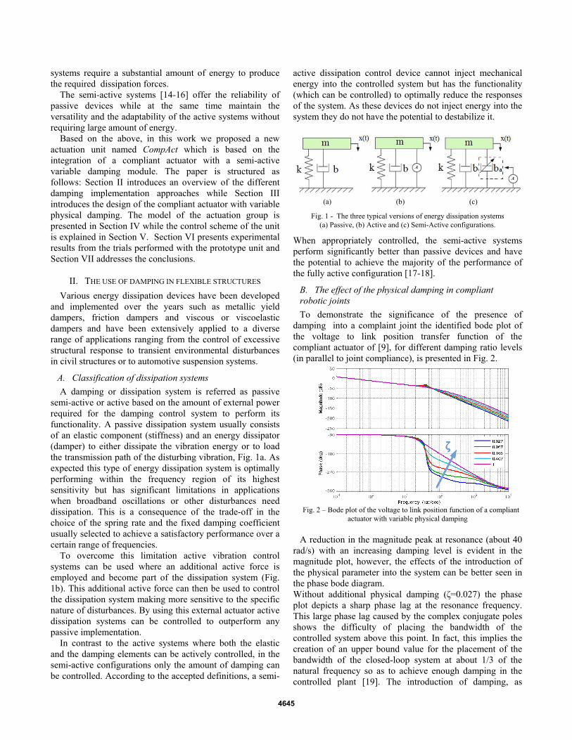
semi-active or active based on the amount of external power required for the damping control system to perform its functionality. A passive dissipation system usually consists of an elastic component (stiffness) and an energy dissipator (damper) to either dissipate the vibration energy or to load the transmission path of the disturbing vibration, Fig. 1a. As expected this type of energy dissipation system is optimally performing within the frequency region of its highest sensitivity but has significant limitations in applications when broadband oscillations or other disturbances need dissipation. This is a consequence of the trade-off in the choice of the spring rate and the fixed damping coefficient usually selected to achieve a satisfactory performance over a certain range of frequencies.
To overcome this limitation active vibration control systems can be used where an additional active force is employed and become part of the dissipation system (Fig. 1b). This additional active force can then be used to control the dissipation system making more sensitive to the specific nature of disturbances. By using this external actuator active dissipation systems can be controlled to outperform any passive implementation.
In contrast to the active systems where both the elastic and the damping elements can be actively controlled, in the semi-active configurations only the amount of damping can be controlled. According to the accepted definitions, a semi-
active dissipation control device cannot inject mechanical energy into the controlled system but has the functionality (which can be controlled) to optimally reduce the responses of the system. As these devices do not inject energy into the system they do not have the potential to destabilize it.
(a) (b) (c) Fig. 1 - The three typical versions of energy dissipation systems
(a) Passive, (b) Active and (c) Semi-Active configurations.
When appropriately controlled, the semi-active systems perform significantly better than passive devices and have the potential to achieve the majority of the performance of the fully active configuration [17-18].
B. The effect of the physical damping in compliant robotic joints To demonstrate the significance of the presence of
damping into a complaint joint the identified bode plot of the voltage to link position transfer function of the compliant actuator of [9], for different damping ratio levels (in parallel to joint compliance), is presented in Fig. 2.
Fig. 2 – Bode plot of the voltage to link position function of a compliant
actuator with variable physical damping A reduction in the magnitude peak at resonance (about 40
rad/s) with an increasing damping level is evident in the magnitude plot, however, the effects of the introduction of the physical parameter into the system can be better seen in the phase bode diagram. Without additional physical damping (ζ=0.027) the phase plot depicts a sharp phase lag at the resonance frequency. This large phase lag caused by the complex conjugate poles shows the difficulty of placing the bandwidth of the controlled system above this point. In fact, this implies the creation of an upper bound value for the placement of the bandwidth of the closed-loop system at about 1/3 of the natural frequency so as to achieve enough damping in the controlled plant [19]. The introduction of damping, as
4645
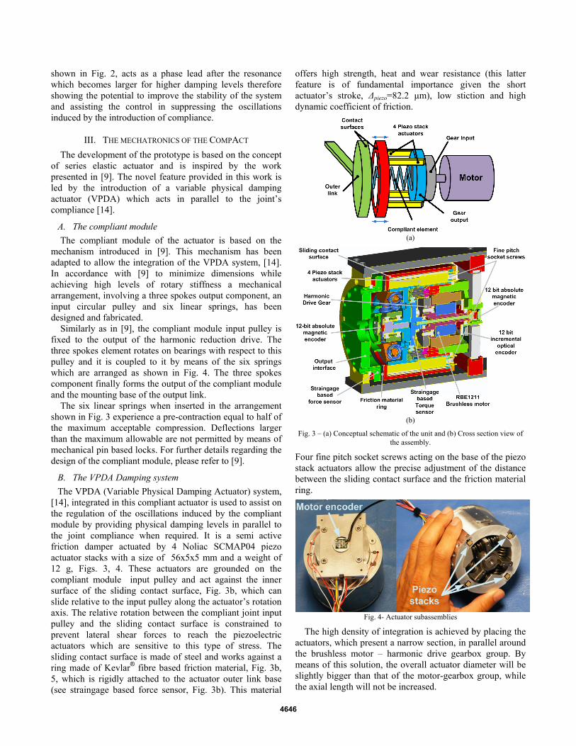
shown in Fig. 2, acts as a phase lead after the resonance which becomes larger for higher damping levels therefore showing the potential to improve the stability of the system and assisting the control in suppressing the oscillations induced by the introduction of compliance.
III. THE MECHATRONICS OF THE COMPACT The development of the prototype is based on the concept
of series elastic actuator and is inspired by the work presented in [9]. The novel feature provided in this work is led by the introduction of a variable physical damping actuator (VPDA) which acts in parallel to the joint’s compliance [14].
A. The compliant module The compliant module of the actuator is based on the
mechanism introduced in [9]. This mechanism has been adapted to allow the integration of the VPDA system, [14]. In accordance with [9] to minimize dimensions while achieving high levels of rotary stiffness a mechanical arrangement, involving a three spokes output component, an input circular pulley and six linear springs, has been designed and fabricated.
Similarly as in [9], the compliant module input pulley is fixed to the output of the harmonic reduction drive. The three spokes element rotates on bearings with respect to this pulley and it is coupled to it by means of the six springs which are arranged as shown in Fig. 4. The three spokes component finally forms the output of the compliant module and the mounting base of the output link.
The six linear springs when inserted in the arrangement shown in Fig. 3 experience a pre-contraction equal to half of the maximum acceptable compression. Deflections larger than the maximum allowable are not permitted by means of mechanical pin based locks. For further details regarding the design of the compliant module, please refer to [9].
B. The VPDA Damping system The VPDA (Variable Physical Damping Actuator) system,
[14], integrated in this compliant actuator is used to assist on the regulation of the oscillations induced by the compliant module by providing physical damping levels in parallel to the joint compliance when required. It is a semi active friction damper actuated by 4 Noliac SCMAP04 piezo actuator stacks with a size of 56x5x5 mm and a weight of 12 g, Figs. 3, 4. These actuators are grounded on the compliant module input pulley and act against the inner surface of the sliding contact surface, Fig. 3b, which can slide relative to the input pulley along the actuator’s rotation axis. The relative rotation between the compliant joint input pulley and the sliding contact surface is constrained to prevent lateral shear forces to reach the piezoelectric actuators which are sensitive to this type of stress. The sliding contact surface is made of steel and works against a ring made of Kevlar® fibre based friction material, Fig. 3b, 5, which is rigidly attached to the actuator outer link base (see straingage based force sensor, Fig. 3b). This material
offers high strength, heat and wear resistance (this latter feature is of fundamental importance given the short actuator’s stroke, Δpiezo=82.2 μm), low stiction and high dynamic coefficient of friction.
(a)
(b)
Fig. 3 – (a) Conceptual schematic of the unit and (b) Cross section view of the assembly.
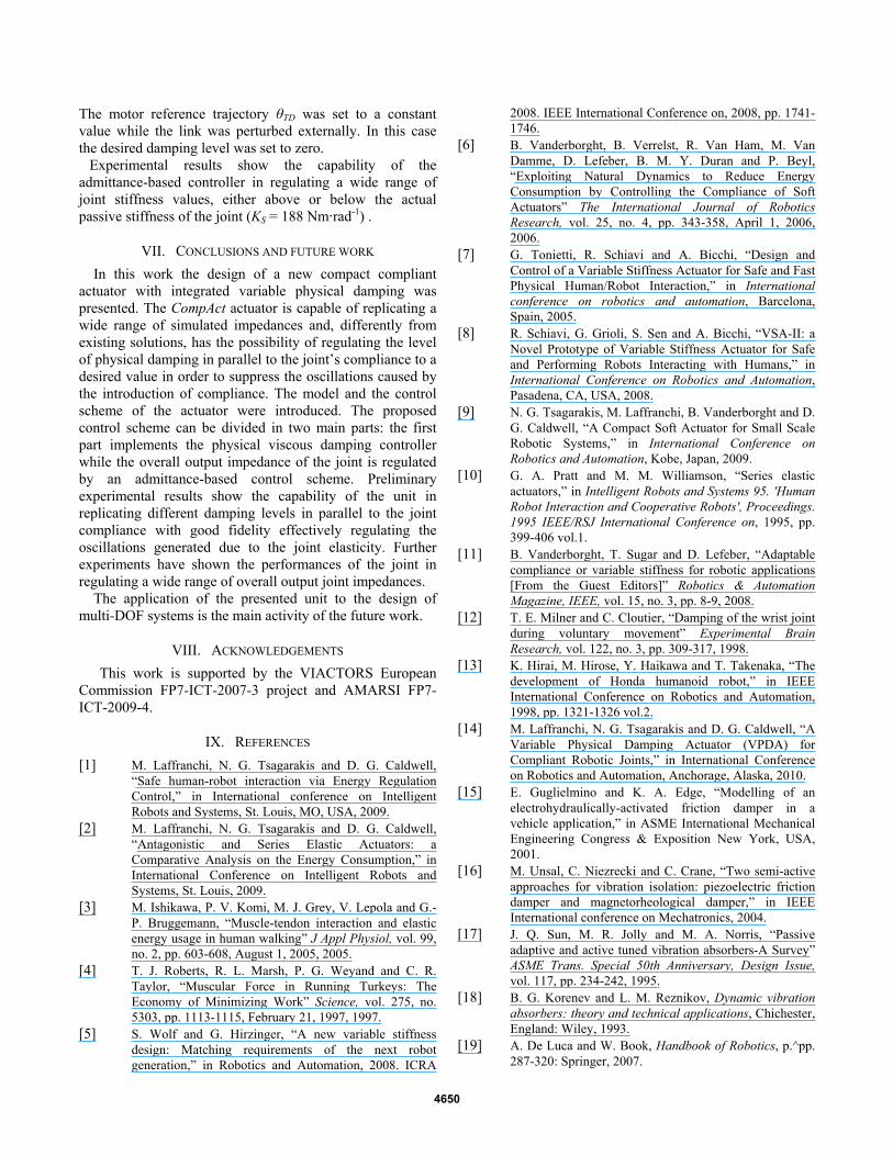
Four fine pitch socket screws acting on the base of the piezo stack actuators allow the precise adjustment of the distance between the sliding contact surface and the friction material ring.
Fig. 4- Actuator subassemblies
The high density of integration is achieved by placing the actuators, which present a narrow section, in parallel around the brushless motor – harmonic drive gearbox group. By means of this solution, the overall actuator diameter will be slightly bigger than that of the motor-gearbox group, while the axial length will not be increased.
4646

C. Sensing A strain gauge based force sensor, Fig. 3b, is machined in
order to allow the measurements of the normal applied by the piezo by means of strain gages. An additional custom made torque sensor measures the torque delivered by the motor at the gear’s output shaft, Fig 3b. Furthermore, two 12bit absolute magnetic position sensors have been integrated within the actuation group to measure the mechanical angle of the motor after the reduction drive and the deflection angle of the compliant module, Figs. 3b, 4. A third incremental 12-bit optical encoder monitors the motor shaft position.
D. Full CompAct unit The fully assembled CompAct unit is shown in Fig. 5.
Fig. 5 – Fully assembled CompAct prototype
A link is fixed at the output of the damper/spring network allowing the installation of different masses which will permit the control of the oscillation frequency.
IV. MODEL AND IDENTIFICATION
A. Mechanical model Figure 6 shows the model of the actuator mechanical
system. The actuator A (please refer to Fig. 6) can regulate the friction torque τf at the link side by applying appropriate force commands Fa. The generated friction torque can be described as:
⎪⎩
⎪⎨⎧
=⋅=
≠⋅=
0),(
0),(
θμτ
θμτ&
&
asf
adf
FG
FG (1)
where μs and μd are the equivalent static and dynamic friction coefficients and G(Fa) takes into account the force generated by the actuator A and the geometry of the contact surfaces.
Fig. 6 - Model of the prototype
In the model of Fig. 6, θr and θ are the angles of the motor before and after the reduction gear of gear ratio N, q is the angle of the link. Jr and Jl are the moments of inertia of the rotor and of the outer link, Dr, Da and Dl are the viscous damping coefficient at the rotor, in parallel to the compliant module Ks and at the outer link, respectively. The torque generated by the actuator is defined as τr while the torque provided to the elastic element of stiffness Ks after the reduction drive is defined as τj. τl is the torque exerted on the system by the load and τf is the friction torque generated by the VPDA system due to the application of the normal force Fa. The model in Fig. 6 can be described by the following set of dynamic equations.
⎪⎩
⎪⎨⎧
=−⋅+−⋅+−⋅+⋅+⋅
=−⋅−−⋅−⋅⋅+⋅⋅
lfsall
jsarr
qqKqDqDqJ
qKqDNDNJ
τθτθθ
τθθθθ
)sgn()()(
)()(22
&&&&&&&
&&&&&
(2)
Assuming uniform pressure over the surface of the ring disk, the friction torque τf can be obtained as a function of the actuator force Fa, the parameters of the ring plate geometry (D; d) and the dynamic friction coefficient μd.
22
33
3 dDdDFad
f −−⋅
=μτ (3)
The static coefficient of friction μs is not considered in (3) because the discontinuous effect of stiction can be neglected due to the friction property of the friction material ring.
From (3), the slope of the line, μTF, relating torque and force, is given by the following expression:
22
33
3 dDdD
Fd
a
fTF −
−==
μτμ (4)
Equation (4) shows that the maximum friction coefficient is achieved by maximizing both the inner and outer ring diameter. However, the mechanical constrains put an upper bound to the maximum achievable diameters; therefore the outer diameter was set equal to the diameter of the actuator (93mm), whereas the inner diameter was set to 66mm which was the highest permitted by the mechanical implementation. For this layout the coefficient μTF was estimated equal to 15·10-3 m. The value of dynamic coefficient of friction for the used interface is μd = 0.4.
B. System identification Equation (2) requires the knowledge of the friction coefficient μTF to fully describe the system. This parameter was experimentally identified using the prototype system. The springs were temporarily removed from the prototype while constant normal force references (in the range Fa = [10, 200]N) were set to the force loop of the VPDA system. At the same time with the link locked to the ground a slowly increasing velocity reference signal was sent to the motor while the delivered torque was recorded by the torque sensor. Experimental results confirm that the stiction effect is almost absent therefore the friction can be modelled as
4647

coulomb friction with good approximation. The obtained results were also used to validate the calculation of (4). The stiffness of the joint was identified to be 188Nm/rad. A detailed identification and model of the stiffness of the compliant module has been presented in [9].
The viscous damping coefficient of the compliant module was estimated using the logarithmic decrement technique and was found to be equal to Da = 0.25 Nms/rad.
The parameters of the system are summarized in Tab. I.
TABLE I SYSTEM PARAMETERS
Parameter Value
Viscous damping of the compliant joint – Da 0.25 Nms·rad-1
Viscous damping at the motor – Dr 1.67·10-3 Nms·rad-1
Viscous damping at the link – Dl 0 Nms·rad-1
Torque/Force coefficient - μTF 15·10-3 m
Kevlar fibre – steel dynamic coefficient of
friction – μd
0.4
Moment of inertia of the motor – Jr 15.02·10-6 kg·m2
Moment of inertia of the link – Jl 110.8·10-3 kg·m2
Stiffness of the joint – Ks 188 Nm·rad-1
Gear ratio – N 100
Diameter – D 93·10-3 m
Length 106·10-3 m
Power 190 W
Peak Torque 40 Nm
Maximum rotary passive deflection ±0.18 rad
Weight 1.8kg
Maximum damping torque 9 Nm
V. SYSTEM CONTROL The control scheme of the actuator can be divided in two
modules. The first module implements the control of the VPDA system which regulates the physical viscous damping in parallel to the compliant element [14], while an admittance-based control component sets the desired overall output impedance of the joint.
A. VPDA system control Considering an equivalent series elastic actuator with
desired damping Dd in parallel to the compliant element and inertial and stiffness properties identical to those of the system of Tab. I it can be written:
⎪⎩
⎪⎨⎧
=−⋅+−⋅+⋅
=−⋅−−⋅−⋅⋅+⋅⋅
lsdl
jsdrr
qKqDqJ
qKqDNDNJ
τθθ
τθθθθ
)()(
)()(22
&&&&
&&&&&
(5)
By equalizing the equilibrium equation for the torque at the output link of (5) with that of (2), the friction torque to be generated by the contact surfaces, τf, can be obtained:
( ) qDqDDq ladf &&&&& ⋅−−⋅−=−⋅ )()sgn( θθτ (6)
expressing the damping coefficient Dd in terms of desired damping ratio ζd:
( ) qDqDKq lalsdf &&&&& ⋅−−⋅−⋅⋅⋅=−⋅ )(J2)sgn( θζθτ
(7)
the force to be applied by the piezoelectric actuators can be finally obtained by combining (7) and (4). It is important to notice that, although the friction is dependent on the sign of the deflection velocity, the solution returned for the positive velocity case gives a positive force also for negative deflection velocities. This force is thus:
( ))sgn(
2θ
μμ
θξ&&&
&&−⋅⋅−
−⋅−⋅⋅⋅= qqDqDJK
FTF
l
TF
alsda
(8)
The force of (8) is affected by the measurement errors of the deflection velocity state and the estimation of the parameters of the system. In order to compensate for these errors, an outer damping ratio loop has been implemented. To realize this, the measurement of the damping ratio is required. The torque sensor (please see Fig. 3b) measures the torque delivered to the compliant element and the parallel damping system.
)()( θθτ −⋅+−⋅= qKqD ssmeas&& (9)
The physical viscous damping in parallel to the compliant element can be measured using the spring deflection state (q-θ), its derivative and the measured torque as follows:
0)(,
0)(,)(
)(
_
_
=−=
≠−−
−⋅−=
θ
θθ
θτ
&&
&&&&
qDD
qKD
dmeass
smeasmeass
(10)
however, when the deflection velocity )( θ&& −q is zero, the damping measurement would return infinite. In order to avoid undesirable behaviour of the system, Ds_meas, ζmeas are set equal to Dd, ζd, respectively, when this condition is verified. The corresponding measured damping ratio is:
0)(,
0)(,)(2
)(
=−=
≠−⋅⋅−⋅
−⋅−=
θξξ
θθ
θτξ
&&
&&&&
q
qJKq
qK
dmeas
ls
smeasmeas
(11)
The overall schematic of the VPDA control module is shown in Fig. 7.
B. Admittance control Assuming that the VPDA system is able to replicate
equivalent physical viscous damping levels Ds as in [14], the torque equilibrium equation for the outer link, (2), transformed in the Laplace domain, becomes:
( ) ( ) lssssll KsDqKsDsDsJ τθ =⋅+⋅−⋅+⋅+⋅+⋅ 2 (12)
Adapting the control scheme proposed in [9] to (12), the motor position reference after the gear θD to be sent to the position controlled system, in order to simulate a certain desired output impedance ZD, is:
4648

)(12 θθθ −⋅⎟⎟⎠
⎞⎜⎜⎝
⎛−
+⋅−⋅−+⋅
+= qZsDsJ
KsD
Dll
ssTDD
(13)
where θTD is the reference trajectory signal while the second term sets the desired simulated impedance of the controlled system. However, (13) requires the knowledge of the actual damping level DS to be implemented. The damping estimator of the VPDA system has been therefore used for this purpose. Equation (13) hence becomes:
)(12_
0 θθθ −⋅⎟⎟⎠
⎞⎜⎜⎝
⎛−
+⋅−⋅−
+⋅+= q
ZsDsJKsD
Dll
smeassTDD
(14)
where Ds_meas is the estimated viscous damping level.
C. Overall Control The block scheme of the overall controller is shown in
Fig. 7. The admittance control scheme is based on a standard PD loop closed around the motor position state, which guarantees asymptotic stability of the closed loop system [19], while the VPDA system, providing variable physical damping in parallel to the compliant joint, suppresses the oscillations generated during free motion or interaction.
Fig. 7 – Control scheme of the actuator
Please notice that without VPDA system damping would have to be introduced actively by closing the loop on the link, however the strong high frequency phase lag exhibited by the motor voltage (or torque) to link position/velocity transfer function shows the difficulties encountered in implementing this solution (refer to Section II.B for further details).
VI. EXPERIMENTAL EVALUATION Experiments have been carried out in order to evaluate the
performance of the mechatronic system when regulating the physical damping in parallel to the joint compliance and the overall actuator stiffness. The experiments were performed using the prototype unit shown in Fig. 5. A first experiment
was conducted to show the capability of the VPDA damping system in replicating desired physical damping levels, while the performances of the unit in regulating the overall joint stiffness are shown in the second part of this section.
A. Damping regulation This experiment was performed by temporarily removing
the springs of the compliant element of the CompAct and controlling the motor to maintain a fixed position. At the same time the VPDA controller was used to replicate different viscous damping levels while the system was externally perturbed. In this case the viscous damping was controlled instead of the damping ratio since for a spring-less system the latter does not have an interpretation.
-4 -3 -2 -1 0 1 2 3 4-6
-4
-2
0
2
4
6
Tor
que
[Nm
]
Velocity [rad/s]
6 Nms/rad experimental data6 Nms/rad curve3.5 Nms/rad experimental data3.5 Nms/rad curve1 Nms/rad experimental data1 Nms/rad curve
Fig. 8 – Damping regulation experiment
The plot in Fig. 8 shows the ability of the VPDA system in regulating any damping levels. It is possible to notice that the stiction effect can be neglected since no vertical lines can be noticed in for the link at rest, Fig. 8. This “stictionless” effect is mainly due to the proper treating of the contact surfaces using the Kevlar®-based friction ring.
B. Stiffness regulation The second experiment aimed to show the capability of the
unit in regulating the overall joint stiffness, Fig. 9.
-1 -0.8 -0.6 -0.4 -0.2 0 0.2 0.4 0.6 0.8 1-50
-40
-30
-20
-10
0
10
20
30
40
50
Angle[rad]
Tor
que[
Nm
]
30Nm/rad curve30Nm/rad experimental data100Nm/rad curve100Nm/rad experimental data220Nm/rad curve220Nm/rad experimental data600Nm/rad curve600Nm/rad experimental data
Fig. 9 – Overall output joint stiffness regulation experiment
4649
The motor reference trajectory θTD was set to a constant value while the link was perturbed externally. In this case the desired damping level was set to zero.
Experimental results show the capability of the admittance-based controller in regulating a wide range of joint stiffness values, either above or below the actual passive stiffness of the joint (KS = 188 Nm·rad-1) .
VII. CONCLUSIONS AND FUTURE WORK In this work the design of a new compact compliant
actuator with integrated variable physical damping was presented. The CompAct actuator is capable of replicating a wide range of simulated impedances and, differently from existing solutions, has the possibility of regulating the level of physical damping in parallel to the joint’s compliance to a desired value in order to suppress the oscillations caused by the introduction of compliance. The model and the control scheme of the actuator were introduced. The proposed control scheme can be divided in two main parts: the first part implements the physical viscous damping controller while the overall output impedance of the joint is regulated by an admittance-based control scheme. Preliminary experimental results show the capability of the unit in replicating different damping levels in parallel to the joint compliance with good fidelity effectively regulating the oscillations generated due to the joint elasticity. Further experiments have shown the performances of the joint in regulating a wide range of overall output joint impedances.
The application of the presented unit to the design of multi-DOF systems is the main activity of the future work.
VIII. ACKNOWLEDGEMENTS This work is supported by the VIACTORS European Commission FP7-ICT-2007-3 project and AMARSI FP7-ICT-2009-4.
IX. REFERENCES [1] M. Laffranchi, N. G. Tsagarakis and D. G. Caldwell,
“Safe human-robot interaction via Energy Regulation Control,” in International conference on Intelligent Robots and Systems, St. Louis, MO, USA, 2009.
[2] M. Laffranchi, N. G. Tsagarakis and D. G. Caldwell, “Antagonistic and Series Elastic Actuators: a Comparative Analysis on the Energy Consumption,” in International Conference on Intelligent Robots and Systems, St. Louis, 2009.
[3] M. Ishikawa, P. V. Komi, M. J. Grey, V. Lepola and G.-P. Bruggemann, “Muscle-tendon interaction and elastic energy usage in human walking” J Appl Physiol, vol. 99, no. 2, pp. 603-608, August 1, 2005, 2005.
[4] T. J. Roberts, R. L. Marsh, P. G. Weyand and C. R. Taylor, “Muscular Force in Running Turkeys: The Economy of Minimizing Work” Science, vol. 275, no. 5303, pp. 1113-1115, February 21, 1997, 1997.
[5] S. Wolf and G. Hirzinger, “A new variable stiffness design: Matching requirements of the next robot generation,” in Robotics and Automation, 2008. ICRA
2008. IEEE International Conference on, 2008, pp. 1741-1746.
[6] B. Vanderborght, B. Verrelst, R. Van Ham, M. Van Damme, D. Lefeber, B. M. Y. Duran and P. Beyl, “Exploiting Natural Dynamics to Reduce Energy Consumption by Controlling the Compliance of Soft Actuators” The International Journal of Robotics Research, vol. 25, no. 4, pp. 343-358, April 1, 2006, 2006.
[7] G. Tonietti, R. Schiavi and A. Bicchi, “Design and Control of a Variable Stiffness Actuator for Safe and Fast Physical Human/Robot Interaction,” in International conference on robotics and automation, Barcelona, Spain, 2005.
[8] R. Schiavi, G. Grioli, S. Sen and A. Bicchi, “VSA-II: a Novel Prototype of Variable Stiffness Actuator for Safe and Performing Robots Interacting with Humans,” in International Conference on Robotics and Automation, Pasadena, CA, USA, 2008.
[9] N. G. Tsagarakis, M. Laffranchi, B. Vanderborght and D. G. Caldwell, “A Compact Soft Actuator for Small Scale Robotic Systems,” in International Conference on Robotics and Automation, Kobe, Japan, 2009.
[10] G. A. Pratt and M. M. Williamson, “Series elastic actuators,” in Intelligent Robots and Systems 95. 'Human Robot Interaction and Cooperative Robots', Proceedings. 1995 IEEE/RSJ International Conference on, 1995, pp. 399-406 vol.1.
[11] B. Vanderborght, T. Sugar and D. Lefeber, “Adaptable compliance or variable stiffness for robotic applications [From the Guest Editors]” Robotics & Automation Magazine, IEEE, vol. 15, no. 3, pp. 8-9, 2008.
[12] T. E. Milner and C. Cloutier, “Damping of the wrist joint during voluntary movement” Experimental Brain Research, vol. 122, no. 3, pp. 309-317, 1998.
[13] K. Hirai, M. Hirose, Y. Haikawa and T. Takenaka, “The development of Honda humanoid robot,” in IEEE International Conference on Robotics and Automation, 1998, pp. 1321-1326 vol.2.
[14] M. Laffranchi, N. G. Tsagarakis and D. G. Caldwell, “A Variable Physical Damping Actuator (VPDA) for Compliant Robotic Joints,” in International Conference on Robotics and Automation, Anchorage, Alaska, 2010.
[15] E. Guglielmino and K. A. Edge, “Modelling of an electrohydraulically-activated friction damper in a vehicle application,” in ASME International Mechanical Engineering Congress & Exposition New York, USA, 2001.
[16] M. Unsal, C. Niezrecki and C. Crane, “Two semi-active approaches for vibration isolation: piezoelectric friction damper and magnetorheological damper,” in IEEE International conference on Mechatronics, 2004.
[17] J. Q. Sun, M. R. Jolly and M. A. Norris, “Passive adaptive and active tuned vibration absorbers-A Survey” ASME Trans. Special 50th Anniversary, Design Issue, vol. 117, pp. 234-242, 1995.
[18] B. G. Korenev and L. M. Reznikov, Dynamic vibration absorbers: theory and technical applications, Chichester, England: Wiley, 1993.
[19] A. De Luca and W. Book, Handbook of Robotics, p.^pp. 287-320: Springer, 2007.
4650