Compact reconfigurable kirigami
16
PHYSICAL REVIEW RESEARCH 3, 043030 (2021) Compact reconfigurable kirigami Gary P. T. Choi , 1 Levi H. Dudte, 2 and L. Mahadevan 2, 3 1 Department of Mathematics, Massachusetts Institute of Technology, Cambridge, Massachusetts 02139, USA 2 School of Engineering and Applied Sciences, Harvard University, Cambridge, Massachusetts 02138, USA 3 Departments of Physics, and Organismic and Evolutionary Biology, Harvard University, Cambridge, Massachusetts 02138, USA (Received 13 February 2021; accepted 27 August 2021; published 13 October 2021) Kirigami involves cutting a flat, thin sheet that allows it to morph from a closed, compact configuration into an open deployed structure via coordinated rotations of the internal tiles. By recognizing and generalizing the geometric constraints that enable this art form, we propose a design framework for compact reconfigurable kirigami patterns, which can morph from a closed and compact configuration into a deployed state conforming to any prescribed target shape, and subsequently be contracted into a different closed and compact configuration. We further establish a condition for producing kirigami patterns and mechanisms which are reconfigurable and rigid deployable allowing us to connect the compact states via a zero-energy family of deployed states. All together, our inverse design framework lays out a path for the creation of shape-morphing material structures. DOI: 10.1103/PhysRevResearch.3.043030 I. INTRODUCTION Kirigami is the art of using cuts in a single sheet of paper that allow for changes in the shape of the sheet via coordi- nated rotations of the connected facets. In recent years, the art form has motivated the design of metamaterials wherein architected cuts on a flat, thin sheet of material can lead to unusual properties not found in most naturally occurring materials, such as a negative Poisson’s ratio [1]. There have been a vast number of studies on the geometry, topology, and mechanics of kirigami [2–8] with applications to the design of nanocomposites [9,10], shape-morphing sheets [11,12], inflatable structures [13], soft robots [14], etc. Almost with- out exception, the deployed kirigami structures are open and periodic, and the property of admitting multiple closed and compact contracted states has been addressed only in a few well-known periodic regular kirigami patterns [15–17], and lead to states that are related to each other via global rotations. This raises a natural question: Is it possible to introduce cuts on a thin sheet of material in a way that yields a deploy- able and reconfigurable kirigami structure conforming to any prescribed shape and admitting multiple closed and compact contracted states? Here we answer this question in the affir- mative by building on our recent inverse design framework [6] and identifying a set of geometric constraints to achieve both reconfigurability and a range of different energy landscapes associated with the deployment pathway. This allows us to design kirigami patterns that can undergo certain nontrivial shape changes under deployment to achieve a prescribed de- Published by the American Physical Society under the terms of the Creative Commons Attribution 4.0 International license. Further distribution of this work must maintain attribution to the author(s) and the published article’s title, journal citation, and DOI. ployed or contracted shape, while also being reconfigurable and rigid deployable. Since kirigami derives its properties via coordinated ro- tations of the individual cells, it is natural that the problem of kirigami design is close to the design of mechanisms [18–22], in which a set of moving parts are connected by kinematic joints to form a deployable structure. However, we note that while kinematic mechanism designs mainly focus on rigid-deployable structures formed by rigid bars, our inverse kirigami framework is applicable to both rigid and stretchable materials. Furthermore, by focusing on how the angles and edge lengths of the tiles in a given kirigami pattern can be changed to achieve the desired properties, we circumvent the role of designing structural topology for mechanism design. II. RECONFIGURABLE KIRIGAMI DESIGN To crystallize our question in a minimal setting, we consider the quad kirigami patterns, a class of deployable structures obtained by introducing cuts to form quadrilateral tiles connected at hinges [see Fig. 1(a)] with a single global degree of freedom. To determine the size and orientation of the cuts that yield a deployed configuration approximating a prescribed target shape, it is more convenient to work in the deployed space and change the geometry of each tile. In our recent work [6], we have shown that the key criteria for guaranteeing that the deformed deployed configuration yields a valid kirigami pattern, also known as the contractibility constraints, consist of the edge length constraints and the angle sum constraints. As illustrated by the red dotted lines in Fig. 1(a), the edge length constraints enforce the constancy of the length of each pair of edges in the deployed space that correspond to the same edge in the pattern space: a = b, c = d , p = q, r = s. (1) The angle sum constraints enforce the condition that the set of angles {α k } n k=1 (for quad kirigami, n = 4) in the deployed 2643-1564/2021/3(4)/043030(16) 043030-1 Published by the American Physical Society
-
Upload
khangminh22 -
Category
Documents
-
view
6 -
download
0
Transcript of Compact reconfigurable kirigami
PHYSICAL REVIEW RESEARCH 3, 043030 (2021)
Compact reconfigurable kirigami
Gary P. T. Choi ,1 Levi H. Dudte,2 and L. Mahadevan 2,3
1Department of Mathematics, Massachusetts Institute of Technology, Cambridge, Massachusetts 02139, USA2School of Engineering and Applied Sciences, Harvard University, Cambridge, Massachusetts 02138, USA
3Departments of Physics, and Organismic and Evolutionary Biology, Harvard University, Cambridge, Massachusetts 02138, USA
(Received 13 February 2021; accepted 27 August 2021; published 13 October 2021)
Kirigami involves cutting a flat, thin sheet that allows it to morph from a closed, compact configuration intoan open deployed structure via coordinated rotations of the internal tiles. By recognizing and generalizing thegeometric constraints that enable this art form, we propose a design framework for compact reconfigurablekirigami patterns, which can morph from a closed and compact configuration into a deployed state conformingto any prescribed target shape, and subsequently be contracted into a different closed and compact configuration.We further establish a condition for producing kirigami patterns and mechanisms which are reconfigurable andrigid deployable allowing us to connect the compact states via a zero-energy family of deployed states. Alltogether, our inverse design framework lays out a path for the creation of shape-morphing material structures.
DOI: 10.1103/PhysRevResearch.3.043030
I. INTRODUCTION
Kirigami is the art of using cuts in a single sheet of paperthat allow for changes in the shape of the sheet via coordi-nated rotations of the connected facets. In recent years, theart form has motivated the design of metamaterials whereinarchitected cuts on a flat, thin sheet of material can leadto unusual properties not found in most naturally occurringmaterials, such as a negative Poisson’s ratio [1]. There havebeen a vast number of studies on the geometry, topology, andmechanics of kirigami [2–8] with applications to the designof nanocomposites [9,10], shape-morphing sheets [11,12],inflatable structures [13], soft robots [14], etc. Almost with-out exception, the deployed kirigami structures are open andperiodic, and the property of admitting multiple closed andcompact contracted states has been addressed only in a fewwell-known periodic regular kirigami patterns [15–17], andlead to states that are related to each other via global rotations.This raises a natural question: Is it possible to introduce cutson a thin sheet of material in a way that yields a deploy-able and reconfigurable kirigami structure conforming to anyprescribed shape and admitting multiple closed and compactcontracted states? Here we answer this question in the affir-mative by building on our recent inverse design framework [6]and identifying a set of geometric constraints to achieve bothreconfigurability and a range of different energy landscapesassociated with the deployment pathway. This allows us todesign kirigami patterns that can undergo certain nontrivialshape changes under deployment to achieve a prescribed de-
Published by the American Physical Society under the terms of theCreative Commons Attribution 4.0 International license. Furtherdistribution of this work must maintain attribution to the author(s)and the published article’s title, journal citation, and DOI.
ployed or contracted shape, while also being reconfigurableand rigid deployable.
Since kirigami derives its properties via coordinated ro-tations of the individual cells, it is natural that the problemof kirigami design is close to the design of mechanisms[18–22], in which a set of moving parts are connected bykinematic joints to form a deployable structure. However, wenote that while kinematic mechanism designs mainly focus onrigid-deployable structures formed by rigid bars, our inversekirigami framework is applicable to both rigid and stretchablematerials. Furthermore, by focusing on how the angles andedge lengths of the tiles in a given kirigami pattern can bechanged to achieve the desired properties, we circumvent therole of designing structural topology for mechanism design.
II. RECONFIGURABLE KIRIGAMI DESIGN
To crystallize our question in a minimal setting, weconsider the quad kirigami patterns, a class of deployablestructures obtained by introducing cuts to form quadrilateraltiles connected at hinges [see Fig. 1(a)] with a single globaldegree of freedom. To determine the size and orientation ofthe cuts that yield a deployed configuration approximatinga prescribed target shape, it is more convenient to work inthe deployed space and change the geometry of each tile. Inour recent work [6], we have shown that the key criteria forguaranteeing that the deformed deployed configuration yieldsa valid kirigami pattern, also known as the contractibilityconstraints, consist of the edge length constraints and theangle sum constraints. As illustrated by the red dotted linesin Fig. 1(a), the edge length constraints enforce the constancyof the length of each pair of edges in the deployed space thatcorrespond to the same edge in the pattern space:
a = b, c = d, p = q, r = s. (1)
The angle sum constraints enforce the condition that the setof angles {αk}n
k=1 (for quad kirigami, n = 4) in the deployed
2643-1564/2021/3(4)/043030(16) 043030-1 Published by the American Physical Society

CHOI, DUDTE, AND MAHADEVAN PHYSICAL REVIEW RESEARCH 3, 043030 (2021)
FIG. 1. Reconfigurable kirigami design. (a) An enlargement of the unit cell of a quad kirigami tessellation illustrating the constraints onedge lengths and angles to be satisfied [Eqs. (1)–(4)]. The red dotted lines indicate the ordinary edge pairs corresponding to the same cuts,and the blue dotted lines indicate the dual edge pairs for getting the other contracted configuration. (b) The inverse design framework forreconfigurable kirigami. Starting with a given kirigami pattern and a prescribed target shape, we construct an initial guess in the deployedspace and solve a constrained optimization problem to obtain a valid deployed configuration that satisfies both the ordinary contractibilityconstraints, and the new reconfigurability constraints, and matches the target shape. We then contract the deployed configuration in two ways,one by following the cut edge pairs and one by following the dual edge pairs to obtain two contracted states. The angles are colored based onthe correspondence in the kirigami pattern.
space that correspond to the same vertex in the pattern space[see Fig. 1(a)] satisfy
n∑k=1
αk = 2π. (2)
To ensure that the deformed deployed configuration admitsanother closed and compact contracted state, we exploit an un-derlying duality present in the standard quad kirigami patternassociated with reconfigurability, which implies the presenceof dual pairs of length and angle constraints. These read asfollows:
043030-2

COMPACT RECONFIGURABLE KIRIGAMI PHYSICAL REVIEW RESEARCH 3, 043030 (2021)
FIG. 2. The optimization process for producing a reconfigurable kirigami pattern. The two plots show the objective function [Eq. (7)] andthe maximum constraint violation, which takes all constraints in Eqs. (1)–(6) into consideration. We use MATLAB’s fmincon optimizationsolver to iteratively update the coordinates of the nodes and change the pattern from the initial guess to an optimal configuration that matchesthe target shape and satisfies the reconfigurability conditions. As the pattern is reconfigurable, it admits two different closed and compactcontracted states.
(1) Dual edge length constraints. For each pair of adjacentedges belonging to two different tiles and not paired up inEq. (1) [i.e., the blue dotted lines in Fig. 1(a)], we should have
e = f , g = h, p = s, q = r, (3)
noting that each pair of them will then correspond to the sameedge in the reconfigured pattern space.
(2) Dual angle sum constraints. For every set of angles{βk}n
k=1 dual to the set of angles {αk}nk=1 in Eq. (2) inside a
unit cell [Fig. 1(a)], we should have
n∑k=1
βk = 2π, (4)
noting that β1, β2, . . . , βn will then correspond to the samevertex in the reconfigured pattern space.
Altogether, for quad kirigami, the contractibility con-straints proposed in [6] and the reconfigurability constraintsproposed in this work enforce that all edges around each holein the deployed configuration must be equal in length, yieldinga rhombus, and that all angles of the deformed tiles at twoopposite corners of each rhombus hole should add up to 2π .
In addition to the internal constraints, to further ensure thatthe deployed configuration conforms to a prescribed boundaryshape, we must also enforce the shape matching constraints[6] for every boundary node pi:
‖pi − pi‖2 = 0, (5)
where pi is the projection of pi onto the target boundary.
Given the above constraints, we are now in a positionto frame the inverse design framework for reconfigurablekirigami, shown in Fig. 1(b). Given a regular kirigami tessel-lation and a prescribed target shape, we start with an initialguess of the deployed configuration, which can either be atrivial deployment of the standard tessellation, a deformedconfiguration produced by a conformal/quasiconformal map[24,25], or any other methods that preserve the number andconnectedness of the tiles. Almost without exception, anyinitial guess will violate at least some of the constraints incontractibility, reconfigurability, or target shape matching. Toobtain a valid reconfigurable kirigami pattern, we formulate aconstrained optimization problem for the deployed configura-tion with all constraints above together with the nonoverlapconstraints which prevent adjacent tiles from overlapping. Atevery angle between two adjacent faces in the deployed space,we enforce the following inequality [6]:
〈(b − a) × (c − a), �n〉 � 0, (6)
where a and b are two nodes of a face, a and c are two nodesof another face, (b, a, c) form a right-hand ordered anglebetween the two faces, and �n = (0, 0, 1) is the outward unitnormal. Here we simply adopt the objective function used inour previous work [6] to yield a smooth shape change over theentire pattern, noting that other choices are possible:
min1
M
M∑i=1
(∑j
(αi j − βi j )2 +
∑k
(aik − bik )2
), (7)
043030-3

CHOI, DUDTE, AND MAHADEVAN PHYSICAL REVIEW RESEARCH 3, 043030 (2021)
FIG. 3. Reconfigurable kirigami patterns. (a) For each example, the top row shows the two contracted states and the bottom row shows thedeployed state which matches the prescribed target boundary shape [see Fig. 4(a) for more examples]. (b) Reconfigurable kirigami patternsproduced by further enforcing a reflection symmetry constraint in the constrained optimization framework [see Fig. 4(b) for more examples].(c) Energetics of the deployment and contraction of a reconfigurable kirigami pattern shows barriers near the two contracted states, but almostzero energy in between. This results in an unusual landscape, with monostable elastic minima at the ends and a mechanism-like zero-energyphase in between (see also the inset log-scale plot). The insets show the intermediate deployed states with each tile color coded by the totalspring energy along all its edges and diagonals (denoted by e) (see Video S1 [23] and Appendix A for details).
where αi j , βi j are a pair of corresponding angles in two adja-cent cells and aik , bik are corresponding edge lengths in twoadjacent cells, and M is the total number of pairs of adjacentcells.
Expressing all constraints and the objective function interms of the coordinates of the nodes in the deployed configu-ration, we solve this optimization problem using the fminconroutine in MATLAB, where the gradients of the objective func-tion and the constraints are computed analytically and spec-ified in the solver using the SpecifyObjectiveGradientand SpecifyConstraintGradient options. This yields adeformed deployed configuration that satisfies all constraints,from which we can obtain the two contracted states by rotatingthe tiles according to the two sets of edge correspondences.
Figure 2 shows an example of the optimization processby the MATLAB’s fmincon solver. In this example, the targetdeployed shape is a rainbow and we start with the standard
deployed configuration of a quad kirigami pattern as theinitial guess. As all adjacent cells are identical, the initialvalue of the objective function is 0. However, since the targetshape is not matched, the initial constraint violation is large.Throughout the iterations, the solver gradually updates thecoordinates of the nodes to match the target shape, whichresults in a difference in angle and length between adjacentcells and hence the objective function value becomes nonzero.As the optimization process continues, the solver minimizesthe objective function and the constraint violation. Finally, itreaches an optimal solution, a valid deployed configuration ofa reconfigurable kirigami pattern that satisfies the target de-ployed shape and admits two closed and compact contractedstates. Figure 3(a) shows several examples of reconfigurablekirigami patterns obtained by our method, where each ofthe kirigami patterns admits two distinct contracted statesand the deployed configuration conforms to a prescribed
043030-4
COMPACT RECONFIGURABLE KIRIGAMI PHYSICAL REVIEW RESEARCH 3, 043030 (2021)
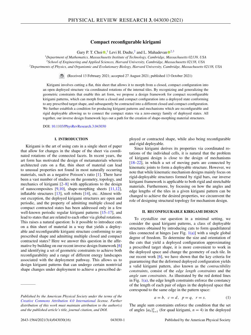
FIG. 4. More examples of reconfigurable quad kirigami patterns with different target boundary shape obtained by our framework.(a) Patterns produced without enforcing any symmetry constraint. For each example, the two closed and compact contracted configurations andthe deployed configuration matching the prescribed target shape are shown. Prescribing a symmetric target boundary shape does not necessarilyyield a symmetric pattern. (b) With an additional left-right symmetry constraint enforced in the constrained optimization framework, thepatterns produced will be symmetric.
intermediate target shape. We see that our method is capa-ble of approximating target shapes with different curvatureproperties, like our previous inverse design framework [6].Additionally, we can also control the boundary shape of acontracted state by introducing additional constraints on theboundary edge lengths and angles, yielding a reconfigurablekirigami pattern that deploys from a contracted rectangle toa circle and then contracts to another shape. Of particularinterest is the fact that it is possible to use microscopic tile
rotations that induce local topological rearrangements to in-duce an effective overall global rotation. In addition, if thedeployed target shape is symmetric, one can further enforcethis as an additional constraint in the optimization frameworkto produce reconfigurable kirigami patterns that are symmetricin the contracted and deployed states [Fig. 3(b)].
The presence of multiple closed and compact contractedstates in these reconfigurable structures naturally implies thepresence of at least a bistable mechanical energy landscape
043030-5
CHOI, DUDTE, AND MAHADEVAN PHYSICAL REVIEW RESEARCH 3, 043030 (2021)
(a)
(b)
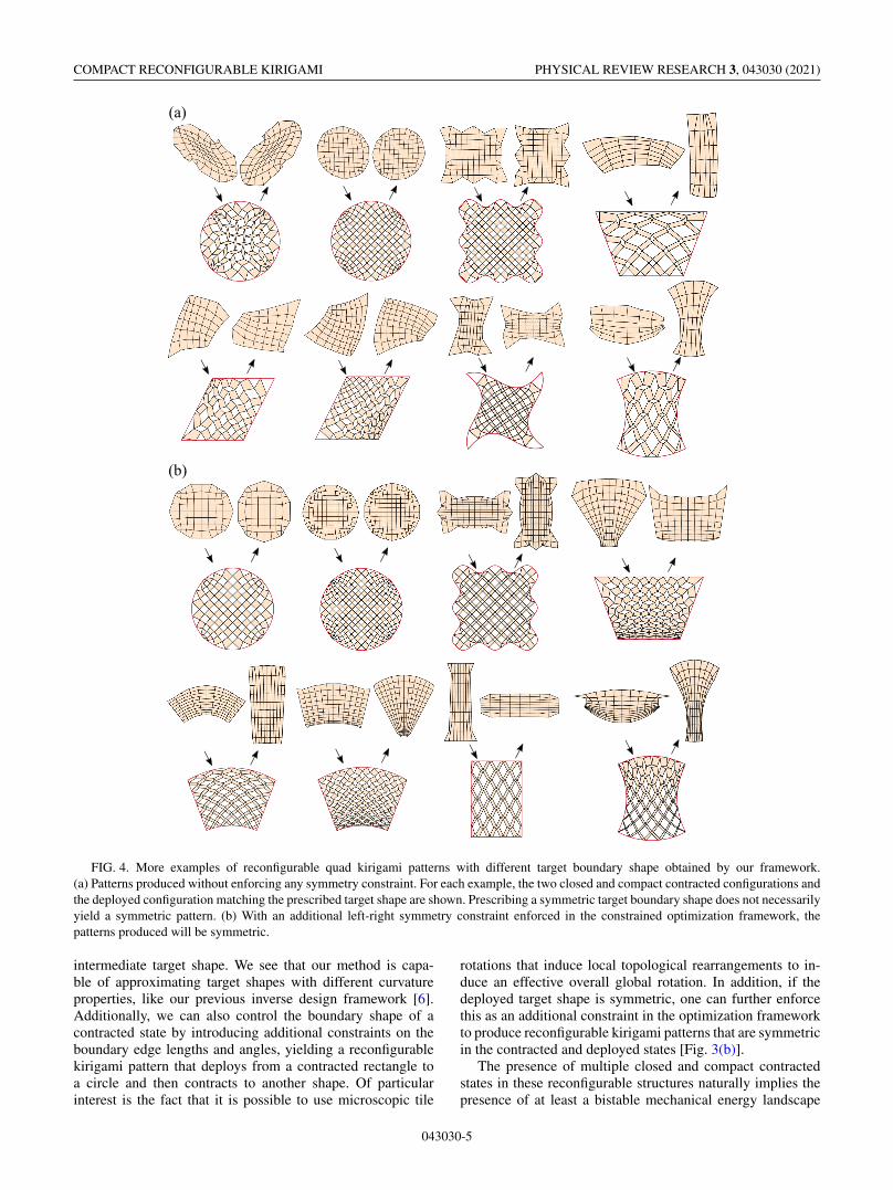
FIG. 5. Conditions for multiple closed, compact contractedkirigami states can be mapped to linkage deployment. (a) The de-ployment of a generic four-bar linkage. The grey lines show thethree deployment paths, two of which (the top and bottom rows)are degenerate. As for the nondegenerate one (the middle row),since the edges are not necessarily equal in length, it is not possibleto achieve multiple closed and compact contracted states. (b) Thedeployment of a reconfigurable four-bar linkage. The grey lines showthe three deployment paths, two of which (the top and bottom rows)are degenerate. As for the nondegenerate one (the middle row), notethat the edges are equal in length and hence it is possible to achievemultiple closed and compact contracted states.
[Fig. 3(c)], with additional minima arising as a function ofnew constraints. To characterize this energy landscape, wequantify the deformation of the tiles by replacing the edgesand diagonals of the quads by linear springs with a totalenergy
E (t ) =∑
i, j:[i, j]∈E
(‖xi(t ) − x j (t )‖ − li j
li j
)2
, (8)
where E is the set of all edges and diagonals, xi(t ) is theposition of the node i at time t , and li j is the rest length of thespring at [i, j] (see Appendix A for more details). When wecalculate the elastic energy as a function of the deploymentstage, we find that the two compact end states are indeedglobal energy minima, but the tiles have to deformed to moveaway from these states. Interestingly, there is a regime ofdeployment where the system is more like a mechanism withthe tiles essentially responding by just rotating [see Fig. 3(c)inset and Video S1 of the Supplemental Material [23]]. Thisis a generic feature of reconfigurable kirigami patterns thatbehave like elastic structures near their compact states, andlike rigid mechanisms away from them.
More reconfigurable kirigami patterns are given in Fig. 4.As shown in Fig. 4(a), the inverse design method may pro-duce asymmetric patterns even if the target boundary shape issymmetric. Figure 4(b) shows examples of symmetric recon-figurable quad kirigami patterns produced by enforcing an ad-ditional left-right symmetry constraint in the constrained op-timization process. More specifically, we first shift the targetpattern such that the symmetry axis is x = 0. We then makeonly the left half nodes (with x < 0) as variables [in the formof (xi, yi ), i = 1, 2, . . . ], while each of the correspondingnodes in the right half is enforced to be (−xi, yi ). The coordi-nates are then used in the optimization process as usual for de-termining the constraint violation and descent direction. It canbe observed that with this additional constraint, the results aremore regular in shape. Note that reconfigurable kirigami pat-terns that approximate a prescribed shape are not necessarilyunique. Using different initial guesses, it is possible to obtaindifferent reconfigurable kirigami patterns. The large variety ofshapes produced demonstrate the flexibility of our framework.
One can also consider each negative space in a quadkirigami pattern as a four-bar linkage to analyze reconfigura-bility. Figure 5 shows the deployments of a generic four-barlinkage and a reconfigurable four-bar linkage respectively. Asillustrated in the middle row of Fig. 5(a), for a generic 2×2quad kirigami pattern, it is not possible to morph the patternfrom a closed and compact contracted configuration to a de-ployed state and then contract it to another closed and compactcontracted configuration while remaining embedded in twodimensions. By contrast, as illustrated in the middle row ofFig. 5(b), for a reconfigurable 2×2 quad kirigami pattern,all four edges of the negative space are equal in length andhence it is possible to achieve multiple closed and compactcontracted configurations.
III. RECONFIGURABLE AND RIGID-DEPLOYABLEKIRIGAMI DESIGN
Our previous example shows that generic quad kirigamipatterns are not single degree-of-freedom mechanisms [6],and thus neither are reconfigurable kirigami patterns that wehave introduced so far. While one may control the stabilityof the patterns by tuning the hinge stiffness as discussed in[6], it is noteworthy that the hinge stiffness is not consideredin the constrained optimization problem and hence has to behandled separately. This raises a natural question: How can wecomplement the geometric constraints in Eqs. (3) and (4) topreserve the single degree of freedom in the kirigami patternsby modifying the proposed inverse design framework withoutintroducing extra steps? Said differently, how can we makequad kirigami rigid-deployable by admitting a single con-tinuous path from one contracted pattern through the solveddeployed state to the second contracted pattern state such thatall the constituent tiles rotate rigidly without deforming? Toenable this, we introduce the following rigid-deployabilityconstraints: around every negative space (i.e., a hole formedby four edges of four neighboring quads), we should have
α1 + α2 = α3 + α4 = β1 + β2 = β3 + β4 = π, (9)
where the design angles are as shown in Fig. 1. Intuitively,note that a four-bar linkage has two one-dimensional rigid
043030-6

COMPACT RECONFIGURABLE KIRIGAMI PHYSICAL REVIEW RESEARCH 3, 043030 (2021)
FIG. 6. An illustration of the constraints for reconfigurable, rigid-deployable kirigami design. Left: In kirigami patterns, each negativespace (blue) formed by a generic deployed quad kirigami structure (not necessarily reconfigurable) is a four-bar linkage with two pairs ofadjacent edges having the same length. Right: If the reconfigurability constraints are enforced, all links in the four-bar linkage have the samelength. Such a linkage has three rigid deployments (shown by the dotted lines), one nontrivial path in which all angles between links areactivated (the horizontal dotted lines with arrows in between the two dark green boxes in the pattern space and the reconfigured pattern space)and two degenerate paths connected by branch points at the ends of the first path (the vertical dotted lines in the green boxes in the patternspace and the reconfigured pattern space). The linkage can deploy rigidly from the branch point into either deployment paths, but cannot rigidlytransform directly between points on the deployment paths while remaining embedded in two dimensions. If Eq. (9) is satisfied, the four-barlinkage in the pattern space will be as shown in the dark green box, and hence there is a rigid deployment path (as indicated by the green ticks)for morphing it from the pattern space to the deployed space and then to the reconfigured pattern space. However, if Eq. (9) is not satisfied,the four-bar linkage in the pattern space will be as shown in the pale green boxes, and so there is no rigid deployment path for reconfiguring it(as indicated by the red crosses).
deployments connected by a single branch point, the config-uration with all edges collinear and an angle of π betweenoverlapping edge pairs at the common hinge (see the top andbottom rows of Figs. 5(a) and 5(b)). The linkage can deployrigidly from the branch point into either deployment paths,but cannot rigidly transform directly between points on thedeployment paths while remaining embedded in two dimen-sions. Therefore, a reconfigurable quad kirigami pattern isrigid-deployable if and only if all edges of each negative spaceare collinear in the contracted configuration. A mathematicaljustification of the constraints stated in Eq. (9) is providedbelow.
Lemma. (Local rigid deployability) A reconfigurablekirigami pattern is locally rigid-deployable if and only if Eq. (9)is satisfied for all negative spaces.
Proof. Equation (9) ensures that each negative space formsa straight line in both contracted configurations. Taken inisolation, each negative space can be thought of as a four-bar linkage (highlighted in blue in Fig. 6, left). A negativespace/four-bar linkage from a generic quad kirigami pat-tern (i.e., one that is not reconfigurable) has two uniqueedge lengths where edges with equal lengths are incident toeach other [see Fig. 5(a)]. Such a four-bar linkage has twoone-dimensional deployment paths in the plane connected toeach other at two branch points, where the edges with equallengths coincide with each other and all edges are collinear.In the plane, the four-bar linkage cannot move from onedeployment path to another except at and through a branch
point. Thus, quad kirigami patterns which do not satisfy therigid-deployability constraints contain negative spaces whichcannot pass from pattern to deployed states in the plane with-out changing edge lengths. And, conversely, quad kirigamipatterns which satisfy the rigid-deployability constraints haveonly negative spaces which can rigidly deform from theirstraight-line pattern configurations to their solved, deployedconfigurations in the plane. Reconfigurable quad kirigamistructures have negative spaces/four-bar linkages with alllengths being equal [see Fig. 5(b)]. Such linkages have threeone-dimensional deployment paths, one path in which allhinges are activated and the linkage forms a rhombus, andtwo degenerate paths in which two of the four hinges in thelinkage are activated, each connected to the rhombus path ata respective branch point (Fig. 6, right). Thus, reconfigurablequad kirigami patterns satisfying Eq. (9) have only negativespaces which can rigidly deform from their two straight-linepattern configurations to their solved, deployed configura-tions in the plane and hence are locally rigid deployable.And thus if Eq. (9) is violated for some negative space in areconfigurable quad kirigami pattern, the pattern cannot belocally rigid deployable as the four-bar linkage cannot rigidlymove to a branch point while remaining embedded in twodimensions. �
We now prove the following result:Theorem 1. (Global rigid deployability) A reconfigurable
kirigami pattern is globally rigid-deployable if and only ifEq. (9) is satisfied for all negative spaces.
043030-7

CHOI, DUDTE, AND MAHADEVAN PHYSICAL REVIEW RESEARCH 3, 043030 (2021)
FIG. 7. Reconfigurable, rigid-deployable kirigami patterns. (a) The deployment of a reconfigurable and rigid-deployable kirigami patternat different states [see also Video S2 [23] and Fig. 8(a)]. The rigid-deployability constraints lead to a flat energy landscape, which indicates thatthe tiles do not deform throughout the process. Each black curve shows the trajectory of a tile center, with the black dot indicating its currentposition. The color of each tile indicates the orientation change (θ ) with respect to the initial contracted state. (b) The deployment of two otherreconfigurable and rigid-deployable kirigami patterns (see Fig. 9 for more examples). (c) Transforming the square to a circle [see also VideoS3 [23] and Figs. 8(b) and 10 for more examples].
Proof. The above lemma provides local rigid deployabil-ity if and only if the constraints in Eq. (9) are satisfied foreach negative space in the pattern. To analyze global rigiddeployability, we construct a loop condition F around a singleinterior face in a generic (i.e., not necessarily reconfigurable)quad kirigami which must be identity at all points along a rigiddeployment. As shown in Fig. 6, let θi, j be design angles andφi, j be deployment angles in a quad kirigami four-bar linkagenegative space. Let fi be the function that transfers a deploy-ment angle φi,1 to the deployment angle φi+1,1 by composingangle-sum transfer hi and four-bar kinematics transfer fi suchthat
φi+1,1 = fi(φi,1) = gi[hi(φi,1)], (10)
φi,2 = hi(φi,1) = 2π − φi,1 − θi,1 − θi,2, (11)
φi+1,1 = gi(φi,2)
= 2 sin−1
⎛⎝ li,2 sin φi,2√l2i,1 + l2
i,2 − 2li,1li,2 cos φi,2
⎞⎠.(12)
If the loop condition
F (φ1,1) = f4( f3( f2( f1((φ1,1))))) = φ1,1 (13)
is satisfied for every value of φ1,1 ∈ [0, 2π − θ1,1 − θ1,2]for every interior quad, then the quad kirigami pattern is
043030-8

COMPACT RECONFIGURABLE KIRIGAMI PHYSICAL REVIEW RESEARCH 3, 043030 (2021)
FIG. 8. Physical models of reconfigurable, rigid-deployable kirigami patterns. (a) A physical model for the pattern in Fig. 7(a) cut froma clear acrylic sheet, with the tops/bottoms of pieces checkerboard colored red and black with permanent marker. (b) A physical model forthe square-to-circle example in Fig. 7(c) cut from a multiply sheet. For each example, the green edges shown in the leftmost panel formthe internal four-bar linkages and black edges complete the quad geometries. Quad interiors have been removed to reduce the weight of themodels. Once the pieces have been laser cut, hinges are formed by applying small strips of light blue tape across pairs of vertical faces incidentto the hinge vertex. The second left panel shows the perspective view of the assembled model. The right panel shows snapshots of the physicalmodel at different states (see also Videos S4 and S5 [23]). All tiles in the physical model are rigid and undergo no deformation throughout thedeployment, while the thickness of the tape joints has some minor effect at the two contracted states and so the model needs to be held stillwith a small external force at the end states.
globally rigid-deployable. In a reconfigurable quadkirigami pattern, we have θi,1 + θi,2 = π and li,1 = li,2and hence φi,2 = hi(φi,1) = π − φi,1, φi+1,1 = gi(φi,2) =π − φi,2, φi+1,1 = fi(φi,1) = φi,1. So F is a composition ofidentity functions fi and is itself identity. Thus, reconfigurablequad kirigami patterns satisfying Eq. (9) are globallyrigid-deployable. �
Therefore, we can obtain reconfigurable kirigami patternswhich are (globally) rigid-deployable by simply augmentingour constrained optimization framework with the additionalcondition (9). In other words, the constrained optimizationnow involves the original contractibility constraints [Eqs. (1)and (2)], the reconfigurability constraints [Eqs. (3) and (4)],the shape matching constraints, the nonoverlap constraints,as well as the rigid-deployability constraints [Eq. (9)]. As aremark, by considering the tiles as rigid parts, our method canalso be used for designing reconfigurable mechanisms.
Figure 7(a) shows a reconfigurable, rigid-deployablekirigami pattern obtained by our method. In contrast to thepatterns in Fig. 3, here each four-bar linkage in the rigid-deployable pattern forms a pair of straight lines in bothcontracted states, and hence there is no geometrical frustra-tion throughout the deployment. The trajectory of the tilesthroughout the deployment and the zero energy associatedwith deployment process confirms that the pattern morphssmoothly from a contracted configuration to a deployedconfiguration and subsequently to another contracted con-figuration (see also Video S2 [23]). It is noteworthy thatthe reconfigurability constraints and the rigid-deployabilityconstraints imply that all negative space rhombi are similar(i.e., congruent up to rescaling). Therefore, the change in theorientation of the tiles forms a checkerboard pattern with amagnitude that is spatially uniform and changes continuouslyfrom 0 to π/2 throughout the deployment and contraction.
Figure 7(b) shows the deployment of two other reconfig-urable, rigid-deployable kirigami patterns. It can again beobserved that each pattern transforms smoothly from one con-tracted configuration to another contracted configuration, andthe orientation change of the tiles forms a checkerboard pat-tern. It is also possible to perform the constrained optimizationdirectly on the two contracted configurations without caringabout the intermediate states (see Appendix B). As a strikingexample of this approach, we revisit the question of circlingthe square [6] via a reconfigurable, rigid-deployable kirigamipattern, with the result shown in Fig. 7(c) (see also Video S3[23]). Note that a major difference between the pattern inFig. 7(c) and the one in Fig. 3(a) is that here the circleshape is achieved at the reconfigured contracted state, while inFig. 3(a) the circle shape is achieved at the deployed state (seeAppendix C for more analyses of the reconfigurable kirigamipatterns and other variations).
To realize our computations in a physical setting, we fab-ricated the model in Fig. 7(a) by laser cutting acrylic plasticsheets and connecting the tiles with tape joints [see Fig. 8(a)],from which we can see that the physical model behavesjust as predicted. We also fabricated another physical modelmade of laser-cut wooden tiles connected with tapes for thesquare-to-circle pattern in Fig. 7(c) [see Fig. 8(b)]. The resultsdemonstrate the flexibility of our proposed reconfigurablekirigami design framework which yields geometric construc-tions that are material independent (see also Appendix D).
Figure 9(a) shows an example of reconfigurable, rigid-deployable kirigami patterns at different resolutions, withtheir deployed shapes approximating the same circle. Byincreasing the cut resolution, a higher accuracy of the approx-imation of the prescribed shape can be achieved. Figure 9(b)shows more examples of reconfigurable, rigid-deployablekirigami patterns. In particular, note that we can obtain a
043030-9

CHOI, DUDTE, AND MAHADEVAN PHYSICAL REVIEW RESEARCH 3, 043030 (2021)
FIG. 9. More examples of reconfigurable, rigid-deployable kirigami patterns with different prescribed target shape. (a) An example ofreconfigurable, rigid-deployable quad kirigami patterns at different resolutions. All four patterns can be deployed to approximate a prescribedcircle. (b) Even with the additional rigid-deployability constraint, our framework is still capable of producing a large variety of patterns thatexhibit highly nontrivial shape change throughout the deployment and contraction process and approximate different target deployed shape.
rigid-deployable example analogous to the structure inFig. 3(a). Figure 10 shows several reconfigurable, rigid-deployable quad kirigami patterns obtained by solving theoptimization problem in the two contracted spaces directly.
IV. EXTENSIONS
While we have primarily focused on the quad kirigami pat-terns so far, other bases such as the kagome (triangle-based)kirigami patterns may also be used to construct reconfigurablekirigami patterns. The key is to identify the reconfigurabilityconstraints analogous to Eqs. (3) and (4) for achieving anotherclosed and compact state for the kagome pattern [Fig. 11(a)].In particular, at each hexagonal negative space, there are twosets of edge length constraints (see the red and blue dotted
lines) to be satisfied. Consequently, all six edges of eachhexagonal negative space must be equal in length in anyreconfigurable kagome kirigami pattern. Figure 11(b) showsa reconfigurable kagome pattern obtained by our frameworkand the deployment and contraction process.
Besides, so far we have limited ourselves to planar kirigamipatterns. We now show how to extend our approach to pro-duce three-dimensional kirigami-based reconfigurable tubularstructures that morph from one contracted configuration intoanother contracted configuration. To achieve these designs, weintroduce cuts into a given target tubular shape into patchesand isometrically unfold them onto the plane. We then ap-ply our constrained optimization framework to produce areconfigurable kirigami pattern for each planar shape, withthe periodicity of the boundaries corresponding to the cuts
043030-10

COMPACT RECONFIGURABLE KIRIGAMI PHYSICAL REVIEW RESEARCH 3, 043030 (2021)
FIG. 10. More examples of reconfigurable, rigid-deployable kirigami patterns obtained by directly solving the optimization problem inthe two contracted spaces. For each pattern, one of the contracted states is enforced to approximate a prescribed shape. (a) An example withthe two contracted states and several intermediate deployed states. (b) More examples obtained by this approach, each exhibiting a significantshape change in between the two contracted states.
enforced. Finally, the patterns are mapped back to the three-dimensional space to form a reconfigurable tubular structure.In Fig. 12(a), we show a three-dimensional kirigami-basedreconfigurable tubular structure that morphs from one con-tracted configuration into another contracted configuration.Figure 12(b) shows another reconfigurable tubular structureachieved by this approach. When compared to the one in
Fig. 12(a), this structure exhibits a smaller axial expansion buta more nonuniform radial change throughout the deploymentand contraction process. More complex reconfigurable tubularstructures can then be constructed using multiple copies of thepatterns obtained by the optimization framework [Fig. 12(c)].
We remark that here we only consider a target 3D tubu-lar shape with zero Gaussian curvature so that we can
FIG. 11. Extending our framework for producing reconfigurable kagome kirigami patterns. (a) The reconfigurability constraints for thekagome pattern. The red and blue dotted lines indicate the ordinary and dual edge correspondences respectively, and the red and blue arcsindicate the ordinary and dual angle correspondences respectively. (b) The deployment and contraction of a reconfigurable kagome kirigamipattern.
043030-11

CHOI, DUDTE, AND MAHADEVAN PHYSICAL REVIEW RESEARCH 3, 043030 (2021)
FIG. 12. Extending our framework for producing reconfigurable tubular structures. (a) Our framework can be extended for creatingreconfigurable tubular structures which morph from one three-dimensional contracted configuration into another three-dimensional contractedconfiguration. Given a target three-dimensional (3D) shape, we first cut and unfold it onto the plane. We then solve the 2D constrainedoptimization problem with an additional periodic boundary constraint to produce a reconfigurable kirigami pattern for the planar shape. Wecan then map the design back to 3D to form a reconfigurable tubular structure. (b) Another reconfigurable tubular structure with a morenonuniform radial change throughout the deployment and contraction process. (c) A more complex reconfigurable tubular structure producedby assembling four copies of the pattern in (b).
isometrically unfold it onto the plane after introducing a cutto get a target 2D shape for the optimization. As the targettubular shape is with zero Gaussian curvature, the deployedconfiguration we obtain should also be with zero Gaussiancurvature in theory. However, note that mapping the 2D re-sult back to the 3D space requires interpolating the 3D nodepositions based on their 2D coordinates, which may involvesmall numerical error that makes the tubular structure slightlycurved [as we can observe in the middle of Figs. 12(b) and12(c)]. As for the two contracted configurations of the tubularstructure, note that they are not necessarily with zero Gaussiancurvature. Analogous to origami structures, these closed andcompact contracted configurations in three dimensions satisfythe angle sum constraints at every vertex but the dihedralangles between the tiles are not necessarily π . Besides, asthe rigid-deployability theory for the 3D case is less clear,here we do not include the rigid-deployability constraints inthe 2D optimization problem. The resulting tubular structuresmay require elastic folding throughout the deployment andcontraction process.
V. DISCUSSION AND CONCLUSION
While many prior works have studied the geometry, topol-ogy, and physics of kirigami patterns, the ability of achieving
multiple closed and compact contracted configurations hasnot been understood. In this paper, we have taken the firststep to explore the possibility of such compact reconfigurabledesign and show that one can achieve reconfigurability inaddition to the shape constraints we introduced in our priorframework [6]. We have further shown that it is possible toenforce rigid-deployability in the inverse design frameworkvia an additional set of geometric constraints. All together, ourapproach exploits the duality in kirigami patterns to create aclass of reconfigurable kirigami patterns and planar mecha-nisms with multiple closed and compact configurations. Justas flat-foldability and rigid-foldability of origami [26] openedthe way for understanding and extending origami designs,perhaps their natural analogs in kirigami, viz. contractibilityand rigid-deployability, that we have uncovered here mightpave the way for a range of art-inspired mathematics, science,and engineering.
ACKNOWLEDGMENTS
This work was supported in part by the National ScienceFoundation under Grants No. DMS-2002103 (G.P.T.C.), No.DMR-2011754 (L.M.), No. DMR-1922321 (L.M.), and No.EFRI-1830901 (L.M.), and the Harvard Quantitative Biol-ogy Initiative and the NSF-Simons Center for Mathematical
043030-12

COMPACT RECONFIGURABLE KIRIGAMI PHYSICAL REVIEW RESEARCH 3, 043030 (2021)
FIG. 13. An example of optimizing the boundary shape of the reconfigured contracted state. Note that only half of the boundary nodesat the reconfigured contracted state (see the blue nodes at the top boundary) can be enforced to lie on the target shape (the red closed curve)precisely. One reason is that the angle sum at the remaining half of the boundary nodes at the reconfigured contracted state (see the purplenodes at the top boundary) is constrained by the rigid-deployability constraints. Another reason is that those purple nodes come from theinterior of the initial contracted state, which are constrained by the angle sum constraints and reconfigurable angle sum constraints therein.Enforcing them to lie on the target curve will introduce additional conditions on the relevant angles, making the problem overconstrained.Nevertheless, increasing the resolution of the kirigami pattern can help achieve a better approximation of the target shape even if only half ofthe boundary nodes in the reconfigured contracted state are controlled.
and Statistical Analysis of Biology at Harvard, Award No.1764269 (G.P.T.C., L.M.).
APPENDIX A: DEPLOYMENT ENERGETICS
To study the deployment energetics of the reconfigurablekirigami patterns, we consider a linear spring model similar tothe model in [6]. Let x1(t ), x2(t ), . . . , xn(t ) be the coordinatesof the nodes in a reconfigurable kirigami pattern at time t ∈[0, 1], where {xi(0)}n
i=1 and {xi(1)}ni=1 correspond to the two
contracted configurations. We introduce a linear spring along
every edge and every diagonal of the tiles and consider thefollowing energy:
E (t )
=∑
i, j:[i, j] is an edge or a diagonal
(‖xi(t ) − x j (t )‖ − li j
li j
)2
, (A1)
where li j is the rest length of the spring at [i, j]. To getthe deployment path, we start with a contracted configura-tion (obtained by the constrained optimization framework)and continuously pull two opposite nodes towards their
FIG. 14. Rigid-deployability constraint violation. (a) A reconfigurable kirigami pattern obtained by our proposed design frameworkwithout imposing the rigid-deployability constraints [Eq. (9)]. (b) A reconfigurable kirigami pattern obtained by our proposed designframework with the rigid-deployability constraints included in the optimization process. In each example, the color of the angles in thefirst contracted state represents the value of log10[erd(α1, α2)], and the color of the angles in the second contacted state represents the value oflog10[erd(β1, β2)], where α1, α2, β1, β2 are the angles described in Eq. (9).
043030-13
CHOI, DUDTE, AND MAHADEVAN PHYSICAL REVIEW RESEARCH 3, 043030 (2021)
corresponding positions in the target deployed configuration(also obtained by the constrained optimization framework).To remove the global translations and rotations of the model,we focus on symmetric patterns and pull two opposite nodesalong the axis of symmetry. At each time point, we solvefor the intermediate deployed configuration by minimizingEq. (A1) subject to the positional constraints of the two nodes.After reaching the target deployed configuration, we repeatthe process by pulling two nodes towards their correspondingpositions in the second contracted configuration (obtained bythe constrained optimization framework).
As guaranteed by the constrained optimization framework,the energy is zero at both contracted configurations and thetarget deployed configuration for any reconfigurable kirigamipattern. This results in a multistable energy landscape. If therigid-deployability constraints are further enforced, all tileswill undergo no deformation throughout the deployment pro-cess and hence E = 0 at all time t theoretically.
APPENDIX B: CONSTRAINED OPTIMIZATIONIN THE TWO CONTRACTED SPACES
As mentioned in the main text, in case it is more desirableto design a reconfigurable kirigami pattern that achieves atarget reconfigured contracted shape without caring about howthe deployed states look like, we can formulate a constrainedoptimization in the two contracted spaces directly.
Denote the initial contracted state by S1 and the reconfig-ured contracted state by S2. Let {xi}n
i=1 and {yi}ni=1 be the nodes
in S1 and S2 respectively. Suppose we would like S2 to approx-imate a prescribed target shape (such as a circle). To solve fora valid reconfigurable and rigid-deployable kirigami patternthat satisfies the requirement, we consider the optimizationover all 2n nodes x1, . . . , xn, y1, . . . , yn (i.e., 4n coordinatesin total) with the following constraints:
(1) Corresponding edges in S1 and S2 should be equal inlength.
(2) Corresponding angles in S1 and S2 should be equal.(3) Rigid-deployability constraints for the angles in S1
(i.e., α1 + α2 = α3 + α4 = β1 + β2 = β3 + β4 = π as dis-cussed in the main text).
(4) Target shape matching constraints for half of theboundary nodes in S2.
(5) (Optional) Boundary shape matching constraints forhalf of the boundary nodes in S1.
The constraints (i) and (ii) ensures the consistency (interms of the edge lengths and the angles) between the twocontracted states. Note that the two constraints are differentfrom the original edge length constraints (which are aboutedge pairs in the same deployed state) and the original anglesum constraints (as the angle sum is automatically 2π inthe contracted states here). The constraints (iii) guarantee therigid-deployability/contractibility by optimizing the angles inone of the contracted states [the constraint (ii) will changethe angles in the other contracted state accordingly]. Theconstraints (iv) and (v) control the boundary shape of the twocontracted states.
For (iv) and (v), note that the shape matching constraintscan only be enforced for the half of the boundary nodeswhich always remain to be at the boundary throughout the
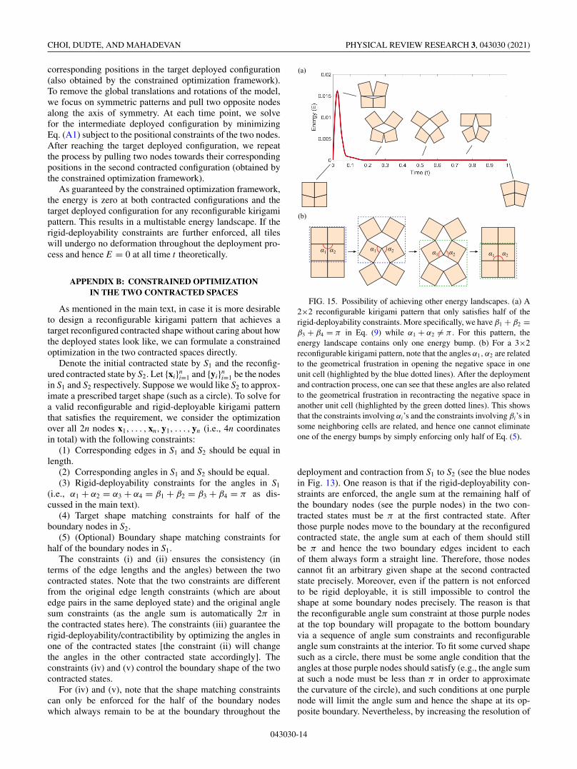
FIG. 15. Possibility of achieving other energy landscapes. (a) A2×2 reconfigurable kirigami pattern that only satisfies half of therigid-deployability constraints. More specifically, we have β1 + β2 =β3 + β4 = π in Eq. (9) while α1 + α2 �= π . For this pattern, theenergy landscape contains only one energy bump. (b) For a 3×2reconfigurable kirigami pattern, note that the angles α1, α2 are relatedto the geometrical frustration in opening the negative space in oneunit cell (highlighted by the blue dotted lines). After the deploymentand contraction process, one can see that these angles are also relatedto the geometrical frustration in recontracting the negative space inanother unit cell (highlighted by the green dotted lines). This showsthat the constraints involving αi’s and the constraints involving βi’s insome neighboring cells are related, and hence one cannot eliminateone of the energy bumps by simply enforcing only half of Eq. (5).
deployment and contraction from S1 to S2 (see the blue nodesin Fig. 13). One reason is that if the rigid-deployability con-straints are enforced, the angle sum at the remaining half ofthe boundary nodes (see the purple nodes) in the two con-tracted states must be π at the first contracted state. Afterthose purple nodes move to the boundary at the reconfiguredcontracted state, the angle sum at each of them should stillbe π and hence the two boundary edges incident to eachof them always form a straight line. Therefore, those nodescannot fit an arbitrary given shape at the second contractedstate precisely. Moreover, even if the pattern is not enforcedto be rigid deployable, it is still impossible to control theshape at some boundary nodes precisely. The reason is thatthe reconfigurable angle sum constraint at those purple nodesat the top boundary will propagate to the bottom boundaryvia a sequence of angle sum constraints and reconfigurableangle sum constraints at the interior. To fit some curved shapesuch as a circle, there must be some angle condition that theangles at those purple nodes should satisfy (e.g., the angle sumat such a node must be less than π in order to approximatethe curvature of the circle), and such conditions at one purplenode will limit the angle sum and hence the shape at its op-posite boundary. Nevertheless, by increasing the resolution of
043030-14

COMPACT RECONFIGURABLE KIRIGAMI PHYSICAL REVIEW RESEARCH 3, 043030 (2021)
FIG. 16. A physical paper model of the reconfigurable and rigid-deployable kirigami pattern in Fig. 7(a). (a) We consider each tile as apolyhedron with certain thickness and create a planar layout pattern with some extra small faces to give height to the folded pieces. (b) Wecan then obtain the paper layout patterns by laser cutting. The paper layout patterns are folded and glued to form the tiles (top), which aresubsequently assembled using tape to form a deployable structure (bottom).
the kirigami pattern, one can approximate the target boundaryshape very well even by enforcing the target shape matchingconstraints for only half of the boundary nodes.
APPENDIX C: ANALYSIS OF THE PATTERNS
1. Quantifying the rigid-deployability constraint violation
To quantify the nonrigid deployability of different kirigamipatterns, we define the rigid-deployability constraint violationby the absolute difference between π and the sum of eachpair of angles described in the rigid-deployability constraints[Eq. (9)]:
erd(α1, α2) = |π − α1 − α2|, (C1)
where α1, α2 are two corresponding angles in Eq. (9).Figure 14 shows two examples of reconfigurable kirigamipatterns with the same target deployed shape. The patternin Fig. 14(a) is obtained via the constrained optimizationwithout imposing the rigid-deployability constraints, whilethe one in Fig. 14(b) is obtained with the rigid-deployabilityconstraints imposed. Note that erd is significantly smaller forthe second example. This can also be observed from thefact that most of the relevant four-bar linkages (the nega-tive spaces) do not form straight lines in the two contractedstates in Fig. 14(a), while those in Fig. 14(b) form visuallystraight lines. More specifically, we have mean(erd) ∼ 10−1
for the first example, while mean(erd) ∼ 10−6 for the secondexample.
We remark that sometimes the constraint violation for thepatterns obtained without enforcing the rigid-deployabilityconstraints can also be small. For example, it can be observedthat the contracted negative spaces in the first circle examplein Fig. 4(b) also form visually straight lines [with mean(erd) ∼10−4]. However, in general, if the rigid-deployability con-straints are not enforced in the optimization problem, it isexpected that the resulting patterns will be with a relativelylarge erd and hence are not rigid deployable. The energylandscape will then be with at least two notable bumps asshown in Fig. 3(c). As discussed in the main text, the vio-lation of the rigid-deployability constraints is related to thechanges in the edge lengths in a negative space/four-barlinkage needed for passing from the contracted state to thedeployed states. Therefore, the energy bumps decrease con-tinuously as the geometry of the kirigami pattern approachesthe rigid-deployable case.
2. More variations
Besides the multistable energy landscape of the reconfig-urable kirigami patterns and the zero energy landscape of thereconfigurable, rigid-deployable kirigami patterns, one maybe interested in achieving other energy landscapes. For asimple 2×2 quad unit cell, note that the first bump in the
043030-15

CHOI, DUDTE, AND MAHADEVAN PHYSICAL REVIEW RESEARCH 3, 043030 (2021)
energy landscape is related to the violation of the first halfof Eq. (9) (i.e., α1 + α2 = α3 + α4 = π ), which is about thegeometrical frustration encountered when opening the nega-tive spaces from the first closed and compact configuration.Similarly, the second energy bump is related to the violationof the latter half of Eq. (5) (i.e., β1 + β2 = β3 + β4 = π ).Therefore, it is natural to ask whether one can achieve anenergy landscape without one of the two energy bumps byenforcing only half of Eq. (5). Indeed, it is possible to obtain a2×2 reconfigurable quad kirigami pattern with such an energylandscape. As shown in Fig. 15(a), if the pattern only satis-fies β1 + β2 = β3 + β4 = π but not α1 + α2 = α3 + α4 = π ,then the resulting energy landscape only contains one energybump. However, for patterns with more tiles, we note that theconstraints involving αi’s and the constraints involving βi’sin some neighboring cells are actually related to each other.As shown in Fig. 15(b), the two angles α1, α2 are related tothe first contracted negative space in the 2×2 unit cell formed
by the top four tiles (blue dotted lines). After the deploymentand contraction process, one can see that these angles are infact also related to the reconfigured contracted negative spacein the 2×2 unit cell formed by the bottom four tiles (greendotted lines). Therefore, if we enforce the first half of Eq. (9)in one unit cell, then it automatically enforces the secondhalf of Eq. (9) for some other unit cell. Hence, for largerpatterns, it is impossible to eliminate only one of the two en-ergy bumps by simply enforcing half of the rigid-deployabilityconstraints.
APPENDIX D: PHYSICAL MODELS
The designed reconfigurable kirigami patterns can be phys-ically realized. Besides the acrylic plastic models and woodenmodels shown in the main text, we show in Fig. 16 an alter-native method to produce physical models with folded paperpieces.
[1] J. N. Grima, A. Alderson, and K. E. Evans, Negative Poisson’sratios from rotating rectangles, Comput. Methods Sci. Technol.10, 137 (2004).
[2] H. Mitschke, V. Robins, K. Mecke, and G. E. Schröder-Turk,Finite auxetic deformations of plane tessellations, Proc. R. Soc.A 469, 20120465 (2013).
[3] S. Shan, S. H. Kang, Z. Zhao, L. Fang, and K. Bertoldi, Designof planar isotropic negative Poisson’s ratio structures, ExtremeMech. Lett. 4, 96 (2015).
[4] A. Rafsanjani and D. Pasini, Bistable auxetic mechanical meta-materials inspired by ancient geometric motifs, Extreme Mech.Lett. 9, 291 (2016).
[5] B. G.-G. Chen, B. Liu, A. A. Evans, J. Paulose, I. Cohen,V. Vitelli, and C. D. Santangelo, Topological Mechanics ofOrigami and Kirigami, Phys. Rev. Lett. 116, 135501 (2016).
[6] G. P. T. Choi, L. H. Dudte, and L. Mahadevan, Programmingshape using kirigami tessellations, Nat. Mater. 18, 999 (2019).
[7] S. Chen, G. P. T. Choi, and L. Mahadevan, Deterministic andstochastic control of kirigami topology, Proc. Natl. Acad. Sci.USA 117, 4511 (2020).
[8] C. Jiang, F. Rist, H. Pottmann, and J. Wallner, Freeform quad-based kirigami, ACM Trans. Graph. 39, 1 (2020).
[9] M. K. Blees, A. W. Barnard, P. A. Rose, S. P. Roberts, K. L.McGill, P. Y. Huang, A. R. Ruyack, J. W. Kevek, B. Kobrin,D. A. Muller et al., Graphene kirigami, Nature (London) 524,204 (2015).
[10] T. C. Shyu, P. F. Damasceno, P. M. Dodd, A. Lamoureux, L.Xu, M. Shlian, M. Shtein, S. C. Glotzer, and N. A. Kotov, Akirigami approach to engineering elasticity in nanocompositesthrough patterned defects, Nat. Mater. 14, 785 (2015).
[11] R. M. Neville, F. Scarpa, and A. Pirrera, Shape morphingkirigami mechanical metamaterials, Sci. Rep. 6, 31067 (2016).
[12] P. Celli, C. McMahan, B. Ramirez, A. Bauhofer, C. Naify, D.Hofmann, B. Audoly, and C. Daraio, Shape-morphing archi-tected sheets with non-periodic cut patterns, Soft Matter 14,9744 (2018).
[13] M. Konakovic-Lukovic, J. Panetta, K. Crane, and M. Pauly,Rapid deployment of curved surfaces via programmable aux-etics, ACM Trans. Graph. 37, 1 (2018).
[14] A. Rafsanjani, Y. Zhang, B. Liu, S. M. Rubinstein, and K.Bertoldi, Kirigami skins make a simple soft actuator crawl,Sci. Robot. 3, eaar7555 (2018).
[15] J. I. Lipton, R. MacCurdy, Z. Manchester, L. Chin, D.Cellucci, and D. Rus, Handedness in shearing auxeticscreates rigid and compliant structures, Science 360, 632(2018).
[16] Y. Yang and Z. You, Geometry of transformable metamateri-als inspired by modular origami, J. Mech. Robot. 10, 021001(2018).
[17] M. Stavric and A. Wiltsche, Geometrical elaboration of auxeticstructures, Nexus Netw. J. 21, 79 (2019).
[18] Z. You and S. Pellegrino, Foldable bar structures, Int. J. SolidsStruct. 34, 1825 (1997).
[19] D. Mao, Y. Luo, and Z. You, Planar closed loop double chainlinkages, Mech. Mach. Theory 44, 850 (2009).
[20] J. M. McCarthy and G. S. Soh, Geometric Design of Linkages,Vol. 11 (Springer, New York, 2010).
[21] Z. You and Y. Chen, Motion Structures: Deployable StructuralAssemblies of Mechanisms (CRC Press, New York, 2011).
[22] T. G. Nelson, T. K. Zimmerman, S. P. Magleby, R. J. Lang,and L. L. Howell, Developable mechanisms on developablesurfaces, Sci. Robot. 4, eaau5171 (2019).
[23] See Supplemental Material at http://link.aps.org/supplemental/10.1103/PhysRevResearch.3.043030 for the videos of the de-ployment of several numerical and physical models producedby our framework.
[24] G. P.-T. Choi and L. M. Lui, A linear formulation for diskconformal parameterization of simply-connected open surfaces,Adv. Comput. Math. 44, 87 (2018).
[25] T. W. Meng, G. P.-T. Choi, and L. M. Lui, TEMPO: Feature-endowed Teichmüller extremal mappings of point clouds,SIAM J. Imaging Sci. 9, 1922 (2016).
[26] T. Kawasaki, On the relation between mountain-creases andvalley-creases of a flat origami, in Proceedings of the 1stInternational Meeting on Origami Science and Technology,edited by H. Huzita (Universita di Padova, Ferrara, Italy, 1989),pp. 229–237.
043030-16