VRTEX 360 COMPACT - Askaynak
56
Register your machine: www.lincolnelectric.com/register Authorized Service and Distributor Locator: www.lincolnelectric.com/locator IM10600 | Issue Date 2/21 © Lincoln Global, Inc. All Rights Reserved. For use with machines having Code Numbers: 13142 +1.888.935.3878 Save for future reference Date Purchased Code: (ex: 10859) Serial: (ex: U1060512345) Operator’s Manual VRTEX ® 360 COMPACT
-
Upload
khangminh22 -
Category
Documents
-
view
3 -
download
0
Transcript of VRTEX 360 COMPACT - Askaynak

Register your machine: www.lincolnelectric.com/register
Authorized Service and Distributor Locator: www.lincolnelectric.com/locator
IM10600 | Issue D ate 2/21
© Lincoln Global, Inc. All Rights Reserved.
For use with machines having Code Numbers:
13142
+1.888.935.3878
Save for future reference
Date Purchased
Code: (ex: 10859)
Serial: (ex: U1060512345)
Operator’s Manual
VRTEX ®
360 COMPACT

ii
INSTALLATIONVRTEX® 360 COMPACT
ii
THANK YOU FOR SELECTING A QUALITY PRODUCT BY LINCOLN ELEC TRIC.
PLEASE EXAMINE CARTON AND EQUIPMENT FORDAMAGE IMMEDIATELY
When this equipment is shipped, title passes to the purchaserupon receipt by the carrier. Consequently, claims for materialdamaged in shipment must be made by the purchaser against thetransportation company at the time the shipment is received.
SAFETY DEPENDS ON YOU
Lincoln arc welding and cutting equipment is designed and builtwith safety in mind. However, your overall safety can be increasedby proper installation ... and thoughtful operation on your part. DO NOT INSTALL, OPERATE OR REPAIR THIS EQUIPMENT WITHOUT READING THIS MANUAL AND THE SAFETYPRECAUTIONS CONTAINED THROUGHOUT. And, most importantly,think before you act and be careful.
This statement appears where the information must be followedexactly to avoid serious personal injury or loss of life.
This statement appears where the information must be followedto avoid minor personal injury or damage to this equipment.
KEEP YOUR HEAD OUT OF THE FUMES.
DON’T get too close to the arc.Use corrective lenses if necessaryto stay a reasonable distanceaway from the arc.
READ and obey the Safety DataSheet (SDS) and the warning labelthat appears on all containers ofwelding materials.
USE ENOUGH VENTILATION orexhaust at the arc, or both, tokeep the fumes and gases from your breathing zone and the general area.
IN A LARGE ROOM OR OUTDOORS, natural ventilation may beadequate if you keep your head out of the fumes (See below).
USE NATURAL DRAFTS or fans to keep the fumes away from your face.
If you de velop unusual symptoms, see your supervisor. Perhaps the welding atmosphere and ventilation system should be checked.
WEAR CORRECT EYE, EAR & BODY PROTECTION
PROTECT your eyes and face with welding helmetproperly fitted and with proper grade of filter plate(See ANSI Z49.1).
PROTECT your body from welding spatter and arcflash with protective clothing including woolenclothing, flame-proof apron and gloves, leatherleggings, and high boots.
PROTECT others from splatter, flash, and glarewith protective screens or barriers.
IN SOME AREAS, protection from noise may be appropriate.
BE SURE protective equipment is in good condition.
Also, wear safety glasses in work areaAT ALL TIMES.
SPECIAL SITUATIONSDO NOT WELD OR CUT containers or materials which previouslyhad been in contact with hazardous substances unless they areproperly cleaned. This is extremely dangerous.
DO NOT WELD OR CUT painted or plated parts unless specialprecautions with ventilation have been taken. They can releasehighly toxic fumes or gases.
Additional precautionary measuresPROTECT compressed gas cylinders from excessive heat,mechanical shocks, and arcs; fasten cylinders so they cannot fall.
BE SURE cylinders are never grounded or part of an electrical circuit.
REMOVE all potential fire hazards from welding area.
ALWAYS HAVE FIRE FIGHTING EQUIPMENT READY FORIMMEDIATE USE AND KNOW HOW TO USE IT.
WARNING
CAUTION
Safety 01 of 04 - 5/16/2018

iii
INSTALLATIONVRTEX® 360 COMPACT
iii
SECTION A:WARNINGS
CALIFORNIA PROPOSITION 65 WARNINGS
WARNING: Breathing diesel engine exhaustexposes you to chemicals known to the Stateof California to cause cancer and birth defects,
or other reproductive harm.• Always start and operate the engine in a
well-ventilated area.• If in an exposed area, vent the exhaust to the outside.• Do not modify or tamper with the exhaust system. • Do not idle the engine except as necessary.For more information go to www.P65 warnings.ca.gov/diesel
WARNING: This product, when used for welding orcutting, produces fumes or gases which containchemicals known to the State of California to causebirth defects and, in some cases, cancer. (CaliforniaHealth & Safety Code § 25249.5 et seq.)
WARNING: Cancer and Reproductive Harmwww.P65warnings.ca.gov
ARC WELDING CAN BE HAZARDOUS. PROTECTYOURSELF AND OTHERS FROM POSSIBLE SERIOUSINJURY OR DEATH. KEEP CHILDREN AWAY. PACEMAKER WEARERS SHOULD CONSULT WITHTHEIR DOCTOR BEFORE OPERATING.
Read and understand the following safety highlights. Foradditional safety information, it is strongly recommended that you purchase a copy of “Safety in Welding & Cutting - ANSI Standard Z49.1” from the American Welding Society, P.O. Box 351040, Miami, Florida 33135 or CSA Standard W117.2-1974. A Free copy of “Arc Welding Safety” booklet E205 is available from the Lincoln Electric Company, 22801 St. Clair Avenue, Cleveland, Ohio 44117-1199.
BE SURE THAT ALL INSTALLATION, OPERATION,MAINTENANCE AND REPAIR PROCEDURES AREPERFORMED ONLY BY QUALIFIED INDIVIDUALS.
FOR ENGINE POWEREDEQUIPMENT.
1.a. Turn the engine off before troubleshootingand maintenance work unless themaintenance work requires it to be running.
1.b. Operate engines in open, well-ventilated areas or vent the engineexhaust fumes outdoors.
1.c. Do not add the fuel near an open flame weldingarc or when the engine is running. Stop theengine and allow it to cool before refueling toprevent spilled fuel from vaporizing on contact
with hot engine parts and igniting. Do not spill fuel when fillingtank. If fuel is spilled, wipe it up and do not start engine untilfumes have been eliminated.
1.d. Keep all equipment safety guards, covers and devices in position and in good repair.Keep hands, hair, clothing and tools away from V-belts, gears, fans and all other moving parts when starting, operating orrepairing equipment.
1.e. In some cases it may be necessary to remove safety guards toperform required maintenance. Remove guards only whennecessary and replace them when the maintenance requiringtheir removal is complete. Always use the greatest care whenworking near moving parts.
1.f. Do not put your hands near the engine fan. Do not attempt tooverride the governor or idler by pushing on the throttle controlrods while the engine is running.
1.g. To prevent accidentally starting gasoline engines while turningthe engine or welding generator during maintenance work,disconnect the spark plug wires, distributor cap or magneto wireas appropriate.
1.h. To avoid scalding, do not remove the radiatorpressure cap when the engine is hot.
ELECTRIC ANDMAGNETIC FIELDS MAYBE DANGEROUS
2.a. Electric current flowing through any conductorcauses localized Electric and Magnetic Fields (EMF). Welding current creates EMF fields around welding cables and welding machines
2.b. EMF fields may interfere with some pacemakers, and welders having a pacemaker should consult their physicianbefore welding.
2.c. Exposure to EMF fields in welding may have other health effectswhich are now not known.
2.d. All welders should use the following procedures in order tominimize exposure to EMF fields from the welding circuit:
2.d.1. Route the electrode and work cables together - Securethem with tape when possible.
2.d.2. Never coil the electrode lead around your body.
2.d.3. Do not place your body between the electrode and workcables. If the electrode cable is on your right side, thework cable should also be on your right side.
2.d.4. Connect the work cable to the workpiece as close as pos-sible to the area being welded.
2.d.5. Do not work next to welding power source.
SAFETY
Safety 02 of 04 - 5/16/2018

iv
INSTALLATIONVRTEX® 360 COMPACT
iv
ELECTRIC SHOCK CAN KILL.
3.a. The electrode and work (or ground) circuits areelectrically “hot” when the welder is on. Donot touch these “hot” parts with your bare skin or wet clothing.Wear dry, hole-free gloves to insulate hands.
3.b. Insulate yourself from work and ground using dry insulation.Make certain the insulation is large enough to cover your full areaof physical contact with work and ground.
In addition to the normal safety precautions, ifwelding must be performed under electricallyhazardous conditions (in damp locations or whilewearing wet clothing; on metal structures such asfloors, gratings or scaffolds; when in crampedpositions such as sitting, kneeling or lying, if thereis a high risk of unavoidable or accidental contactwith the workpiece or ground) use the followingequipment:
• Semiautomatic DC Constant Voltage (Wire) Welder.
• DC Manual (Stick) Welder.
• AC Welder with Reduced Voltage Control.
3.c. In semiautomatic or automatic wire welding, the electrode,electrode reel, welding head, nozzle or semiautomatic weldinggun are also electrically “hot”.
3.d. Always be sure the work cable makes a good electricalconnection with the metal being welded. The connection shouldbe as close as possible to the area being welded.
3.e. Ground the work or metal to be welded to a good electrical (earth)ground.
3.f. Maintain the electrode holder, work clamp, welding cable andwelding machine in good, safe operating condition. Replacedamaged insulation.
3.g. Never dip the electrode in water for cooling.
3.h. Never simultaneously touch electrically “hot” parts of electrodeholders connected to two welders because voltage between thetwo can be the total of the open circuit voltage of bothwelders.
3.i. When working above floor level, use a safety belt to protectyourself from a fall should you get a shock.
3.j. Also see It ems 6.c. and 8.
ARC RAYS CAN BURN.
4.a. Use a shield with the proper filter and cover plates to protect youreyes from sparks and the rays of the arc when welding orobserving open arc welding. Headshield and filter lens shouldconform to ANSI Z87. I standards.
4.b. Use suitable clothing made from durable flame-resistant materialto protect your skin and that of your helpers from the arc rays.
4.c. Protect other nearby personnel with suitable, non-flammablescreening and/or warn them not to watch the arc nor exposethemselves to the arc rays or to hot spatter or metal.
FUMES AND GASESCAN BE DANGEROUS.
5.a. Welding may produce fumes and gaseshazardous to health. Avoid breathing thesefumes and gases. When welding, keep your head out of the fume.Use enough ventilation and/or exhaust at the arc to keep fumesand gases away from the breathing zone. When weldinghardfacing (see instructions on container or SDS)or on lead or cadmium plated steel and othermetals or coatings which produce highly toxicfumes, keep exposure as low as possible andwithin applicable OSHA PEL and ACGIH TLV limitsusing local exhaust or mechanical ventilationunless exposure assessments indicate otherwise.In confined spaces or in some circumstances,outdoors, a respirator may also be required.Additional precautions are also required whenwelding on galvanized steel.
5. b. The operation of welding fume control equipment is affected byvarious factors including proper use and positioning of theequipment, maintenance of the equipment and the specificwelding procedure and application involved. Worker exposurelevel should be checked upon installation and periodicallythereafter to be certain it is within applicable OSHA PEL andACGIH TLV limits.
5.c. Do not weld in locations near chlorinated hydrocarbon vaporscoming from degreasing, cleaning or spraying operations. Theheat and rays of the arc can react with solvent vapors to formphosgene, a highly toxic gas, and other irritating products.
5.d. Shielding gases used for arc welding can displace air and causeinjury or death. Always use enough ventilation, especially inconfined areas, to insure breathing air is safe.
5.e. Read and understand the manufacturer’s instructions for thisequipment and the consumables to be used, including theSafety Data Sheet (SDS) and follow your employer’s safetypractices. SDS forms are available from your weldingdistributor or from the manufacturer.
5.f. Also see item 1.b.
SAFETY
Safety 03 of 04 - 5/16/2018

v
INSTALLATIONVRTEX® 360 COMPACT
v
WELDING AND CUTTINGSPARKS CAN CAUSEFIRE OR EXPLOSION.
6.a. Remove fire hazards from the welding area. Ifthis is not possible, cover them to prevent the welding sparksfrom starting a fire. Remember that welding sparks and hotmaterials from welding can easily go through small cracks andopenings to adjacent areas. Avoid welding near hydraulic lines.Have a fire extinguisher readily available.
6.b. Where compressed gases are to be used at the job site, specialprecautions should be used to prevent hazardous situations.Refer to “Safety in Welding and Cutting” (ANSI Standard Z49.1)and the operating information for the equipment being used.
6.c. When not welding, make certain no part of the electrode circuit istouching the work or ground. Accidental contact can causeoverheating and create a fire hazard.
6.d. Do not heat, cut or weld tanks, drums or containers until theproper steps have been taken to insure that such procedures will not cause flammable or toxic vapors from substances inside.They can cause an explosion even though they have been“cleaned”. For information, purchase “Recommended SafePractices for the Preparation for Welding and Cutting ofContainers and Piping That Have Held Hazardous Substances”,AWS F4.1 from the American Welding Society (see address above).
6.e. Vent hollow castings or containers before heating, cutting orwelding. They may explode.
6.f. Sparks and spatter are thrown from the welding arc. Wear oil freeprotective garments such as leather gloves, heavy shirt, cufflesstrousers, high shoes and a cap over your hair. Wear ear plugswhen welding out of position or in confined places. Always wearsafety glasses with side shields when in a welding area.
6.g. Connect the work cable to the work as close to the welding areaas practical. Work cables connected to the building framework orother locations away from the welding area increase thepossibility of the welding current passing through lifting chains,crane cables or other alternate circuits. This can create firehazards or overheat lifting chains or cables until they fail.
6.h. Also see item 1.c.
6.I. Read and follow NFPA 51B “Standard for Fire Prevention DuringWelding, Cutting and Other Hot Work”, available from NFPA, 1Batterymarch Park, PO box 9101, Quincy, MA 022690-9101.
6.j. Do not use a welding power source for pipe thawing.
CYLINDER MAY EXPLODE IFDAMAGED.
7.a. Use only compressed gas cylinders containingthe correct shielding gas for the process usedand properly operating regulators designed forthe gas and pressure used. All hoses, fittings,etc. should be suitable for the application andmaintained in good condition.
7.b. Always keep cylinders in an upright position securely chained toan undercarriage or fixed support.
7.c. Cylinders should be located:
• Away from areas where they may be struck or subjectedto physical damage.
• A safe distance from arc welding or cutting operationsand any other source of heat, sparks, or flame.
7.d. Never allow the electrode, electrode holder or any otherelectrically “hot” parts to touch a cylinder.
7.e. Keep your head and face away from the cylinder valve outletwhen opening the cylinder valve.
7.f. Valve protection caps should always be in place and hand tightexcept when the cylinder is in use or connected for use.
7.g. Read and follow the instructions on compressed gas cylinders,associated equipment, and CGA publication P-l, “Precautions forSafe Handling of Compressed Gases in Cylinders,” available fromthe Compressed Gas Association, 14501 George Carter WayChantilly, VA 20151.
FOR ELECTRICALLYPOWERED EQUIPMENT.
8.a. Turn off input power using the disconnectswitch at the fuse box before working on the equipment.
8.b. Install equipment in accordance with the U.S. National ElectricalCode, all local codes and the manufacturer’s recommendations.
8.c. Ground the equipment in accordance with the U.S. NationalElectrical Code and the manufacturer’s recommendations.
Refer tohttp://www.lincolnelectric.com/safety
for additional safety information.
SAFETY
Safety 04 of 04 - 5/16/2018

vi
INSTALLATIONVRTEX® 360 COMPACT
vi
SAFETY
Electromagnetic Compatibility (EMC)
ConformanceProducts displaying the CE mark are in conformity with European Community Council Directive of 15 Dec2004 on the approximation of the laws of the Member States relating to electromagnetic compatibility,2004/108/EC. It was manufactured in conformity with a national standard that implements a harmonizedstandard: EN 60974-10 Electromagnetic Compatibility (EMC) Product Standard for Arc Welding Equipment.It is for use with other Lincoln Electric equipment. It is designed for industrial and professional use.
IntroductionAll electrical equipment generates small amounts of electromagnetic emission. Electrical emission may betransmitted through power lines or radiated through space, similar to a radio transmitter. When emissionsare received by other equipment, electrical interference may result. Electrical emissions may a�ect manykinds of electrical equipment; other nearby welding equipment, radio and TV reception, numerical controlledmachines, telephone systems, computers, etc. Be aware that interference may result and extra precautionsmay be required when a welding power source is used in a domestic establishment.
Installation and UseThe user is responsible for installing and using the welding equipment according to the manufacturer’sinstructions. If electromagnetic disturbances are detected then it shall be the responsibility of the user of thewelding equipment to resolve the situation with the technical assistance of the manufacturer. In some casesthis remedial action may be as simple as earthing (grounding) the welding circuit, see Note. In other cases itcould involve construction of an electromagnetic screen enclosing the power source and the work completewith associated input �lters. In all cases electromagnetic disturbances must be reduced to the point wherethey are no longer troublesome.
Note: The welding circuit may or may not be earthed for safety reasons according to nationalcodes. Changing the earthing arrangements should only be authorized by a person who iscompetent to access whether the changes will increase the risk of injury, e.g., by allowingparallel welding current return paths which may damage the earth circuits of other equipment.
Assessment of AreaBefore installing welding equipment the user shall make an assessment of potential electromagnetic prob-lems in the surrounding area. The following shall be taken into account:
a) other supply cables, control cables, signaling and telephone cables; above, below and adjacent to thewelding equipment;
b) radio and television transmitters and receivers;
c) computer and other control equipment;
d) safety critical equipment, e.g., guarding of industrial equipment;
e) the health of the people around, e.g., the use of pacemakers and hearing aids;
f) equipment used for calibration or measurement
g) the immunity of other equipment in the environment. The user shall ensure that other equipment beingused in the environment is compatible. This may require additional protection measures;
h) the time of day that welding or other activities are to be carried out.

vii
INSTALLATIONVRTEX® 360 COMPACT
vii
SAFETY
Electromagnetic Compatibility (EMC)
The size of the surrounding area to be considered will depend on the structure of the building and otheractivities that are taking place. The surrounding area may extend beyond the boundaries of the premises.
Methods of Reducing Emissions
Mains SupplyWelding equipment should be connected to the mains supply according to the manufacturer’s recommenda-tions. If interference occurs, it may be necessary to take additional precautions such as �ltering of the mainssupply. Consideration should be given to shielding the supply cable of permanently installed welding equip-ment, in metallic conduit or equivalent. Shielding should be electrically continuous throughout its length. Theshielding should be connected to the welding power source so that good electrical contact is maintainedbetween the conduit and the welding power source enclosure.
Maintenance of the Welding EquipmentThe welding equipment should be routinely maintained according to the manufacturer’s recommendations.All access and service doors and covers should be closed and properly fastened when the welding equip-ment is in operation. The welding equipment should not be modi�ed in any way except for those changesand adjustments covered in the manufacturers instructions. In particular, the spark gaps of arc striking andstabilizing devices should be adjusted and maintained according to the manufacturer’s recommendations.
Welding CablesThe welding cables should be kept as short as possible and should be positioned close together, running ator close to oor level.
Equipotential BondingBonding of all metallic components in the welding installation and adjacent to it should be considered.However, metallic components bonded to the work piece will increase the risk that the operator couldreceive a shock by touching these metallic components and the electrode at the same time. The operatorshould be insulated from all such bonded metallic components.
Earthing of the WorkpieceWhere the workpiece is not bonded to earth for electrical safety, not connected to earth because of its sizeand position, e.g., ships hull or building steelwork, a connection bonding the workpiece to earth may reduceemissions in some, but not all instances. Care should be taken to prevent the earthing of the workpieceincreasing the risk of injury to users, or damage to other electrical equipment. Where necessary, the connec-tion of the workpiece to earth should be made by a direct connection to the workpiece, but in some countrieswhere direct connection is not permitted, the bonding should be achieved by suitable capacitance, selectedaccording to national regulations.
Screening and ShieldingSelective screening and shielding of other cables and equipment in the surrounding area may alleviate prob-lems of interference. Screening of the entire welding installation may be considered for special applications 1.
_________________________
1 Portions of the preceding text are contained in EN 60974-10: “Electromagnetic Compatibility (EMC) prod-uct standard for arc welding equipment.”

viii
INSTALLATIONVRTEX® 360 COMPACT TABLE OF CONTENTSVRTEX® 360 COMPACT
Page
Installation ....................................................................................................................... Graphic Symbols That May Appear On This Machine Or In This Manual ............................................1 Technical Specifications ..................................................................................................................2 Safety Precautions ...........................................................................................................................3 Select Suitable Location ..................................................................................................................4 Environmental Area .........................................................................................................................4 Stacking ..........................................................................................................................................4 Tilting ..............................................................................................................................................4 Transport .........................................................................................................................................5 High Frequency Interference Protection ...........................................................................................5 Radio Frequency Interference ..........................................................................................................5 Product Description .........................................................................................................................6 User Interface Overview ...................................................................................................................7 Component Overview ......................................................................................................................9 Hardware Specifics........................................................................................................................11 Hardware Uncrating .......................................................................................................................13 Setup Procedure ............................................................................................................................13 Device Labels ................................................................................................................................16
Operation ......................................................................................................................... Powering On ..................................................................................................................................17 License Agreement ........................................................................................................................17 Welding / Cutting Selection Screen ................................................................................................17 User Mode ............................................................................................................................... 18-27 User Mode .............................................................................................................................18 Login Screen ..........................................................................................................................18 Coupon Configuration Selection Screen ..................................................................................19 Process Selection Screen .......................................................................................................19 Table Setup Screens ..............................................................................................................19 Environment Screen ...............................................................................................................20 Parameter Setup Screen ........................................................................................................21 Virtual Welding Overview ........................................................................................................22 Visual Cues ............................................................................................................................22 GTAW Cues ............................................................................................................................23 LASER Screen ........................................................................................................................25 Technique Parameters ............................................................................................................25 Pass Number .........................................................................................................................26 Travel Direction ......................................................................................................................26 Bead Render ..........................................................................................................................27 Discontinuity Indicator ............................................................................................................27 Score .....................................................................................................................................27 Student Report .......................................................................................................................27 Instructor Mode ....................................................................................................................... 28-40 Instructor Mode And Admin Access ........................................................................................28 Weldometer ...........................................................................................................................29 Tolerance Editor .....................................................................................................................30 Scoring Modules ....................................................................................................................33 Update ...................................................................................................................................33 Settings .................................................................................................................................34 Additional Features ........................................................................................................................35

ix
INSTALLATIONVRTEX® 360 COMPACT
Page
Maintenance .................................................................................................................... Cleaning & Maintenance ................................................................................................................41
Troubleshooting .............................................................................................................. How To Use Troubleshooting Guide ................................................................................................42 Troubleshooting Guide ............................................................................................................. 43-44
Diagrams .......................................................................................................................... Dimensions ...................................................................................................................................45 Wiring Diagram .............................................................................................................................46
Parts ............................................................................................ parts.lincolnelectric.com

1
INSTALLATIONVRTEX® 360 COMPACT
FUSE
READ THIS MANUAL COMPLETELY
OFF
GTAW WELDING
SMAW WELDING
ON
USB
INPUT POWER
GMAW WELDING
INPUT VOLTAGE
VIRTUAL REALITY WELDING
WARNING OR CAUTIONDocumentation must be con-sulted in all cases where this symbol is displayed.
HDMI
SHOCK HAZARD
INPUT CURRENT
COUPON ARM CONNECTION
POWER BUTTON
EXTERNAL MONITOR
U1
I1
GRAPHIC SYMBOLS THAT MAY APPEAR ON THIS MACHINE OR IN THIS MANUAL

2
INSTALLATIONVRTEX® 360 COMPACT
TECHNICAL SPECIFICATIONSINPUT
MODEL DESCRIPTION INPUT VOLTAGE± 10%
INPUT CURRENT(MAX.)
K4914-1 SINGLE USER 115/230 VAC (50/60 HZ) 2/1A SINGLE PHASE
THIS PRODUCT INCORPORATES A PROTECTIVE EARTH CIRCUIT IN THE AC POWER CORD. THE AC PLUG SHOULD ONLY BE INSERTED INTO A SOCKET OUTLET PROVIDED WITH A PROTECTIVE EARTH CONTACT. THE MAIN POWER DISCONNECT IS LOCATED IN THE REAR OF THE MACHINE. NOTE: INSTALLATION CATEGORY II EQUIPMENT.
PHYSICAL DIMENSIONS (MACHINE)HEIGHT WIDTH DEPTH WEIGHT
15.0 in.380 mm
12.0 in.305 mm
18.0 in.457 mm
23 lbs.14 kgs.
TEMPERATURE RANGESOPERATING TEMPERATURE RANGE STORAGE TEMPERATURE RANGE
40° - 95° F (5° - 35° C) 32° - 149° F (0° - 65° C)
RELATIVE HUMIDITY* OPERATING ALTITUDE80% For Temperatures Up To 88° F / 31° C
50% @ 104° F / 40° C6562 Feet (2000 Meters)
ENVIRONMENTThis product is for use in Pollution Degree 2 environments (Laboratories, Test Stations, Office Environment).
WARNING

3
INSTALLATIONVRTEX® 360 COMPACT
Read entire installation section before starting installation.
Do not place objects on the VR Table, Arm or on Machine.
During lightning storms, turn off the system and unplug it from the power outlet.
Before using the headset please carefully read these safety instructions.
Read this handbook and use the headset device in strict accordance in order to prevent any damage to your eyes, other injury, loss of visual functions, property damage or death.
We strongly advise you to get familiar with the headset device and its capabilities before you use it for the first time.
SAFETY PRECAUTIONS
ELECTRIC SHOCK can kill.• Only qualified personnel should perform this
installation.• Turn the input power OFF and unplug the machine from
the receptacle before working on this equipment. • Always connect the VRTEX to a power supply grounded
according to the National Electrical Code and local codes.• Do not use or store the headset when wet or in wet areas.• Do not wrap the cable around your neck, body or arms.
-------------------------------------------------------------------------
Misuse or overuse of this product may injure your eyes or affect visual function.
Overexposure to video and flashing light may cause or aggravate the following health effects to light-sensitive users:
• Eye disease and/or injury, Glaucoma.
• Epileptic (and other) Seizures.
• Heart disease or high blood pressure.
Consult your physician before using the headset if you have been diagnosed with or are susceptible to any of the above health effects.
Some users may experience a seizure when exposed to certain visual images, including flashing lights or patterns. Even people who have no history of seizures or epilepsy may have an undiagnosed condition that can cause “photosensitive epileptic seizures.”
Seizures may cause loss of consciousness or convulsions that can lead to injury from falling down or striking nearby objects.
Do not use the headset when you are drowsy or fatigued.
Immediately, stop using the Headset and consult your physician if you experience any of the following symptoms:
• Double vision or inability to focus on the display.
• Nausea or motion sickness.
• Eye fatigue or irritation.
• Headaches or dizziness.
• Aches and pain in the neck or shoulders.
HEADSET SAFETY PRECAUTIONS
Adjust the headband so the headset is secure and will not fall off in use. Do not use the headset if temperature is below 32°F/0°C or above 104°F/40°C or in wet, humid, dusty or smoky areas.
Avoid dropping or impact of the headset frame and displays. If the headset is damaged contact your retailer. There are no user serviceable parts. Only qualified service personnel should perform any repair on this product.
Avoid exposing the headset to direct sunlight or intense / high-powered lighting.
Please see the included headset manual for further precautions regarding the use of the VR headset.
ESD SENSITIVITY
This headset eyepiece device may be sensitive to electrostatic discharge of 8 kV or higher. Observe static precautions such as discharging the body by touching the metal chassis of the grounded equipment prior to touching the eyepiece.
WARNING
CAUTION

SELECT SUITABLE LOCATION
The machine will not operate in harsh environments. It is important that simple preventative measures are followed in order to assure long life and reliable operation. This product is for INDOOR USE ONLY.
• Dirt and dust that can be drawn into the machine should be kept to a minimum. Failure to observe these precautions can result in excessive operating temperatures and nuisance shutdown.
• See Technical Specifications for operating environment conditions.
• Do not place machine where monitor and/or headset is exposed to direct sunlight or high powered lighting.
• Do not place equipment near radiant heat sources.
• Do not place in a confined space. Allow a minimum of three feet of clearance around machine and stand at all times. Adequate ventilation is necessary.
• The fused power switch on the rear panel is the input power disconnect device. Do not position the equipment so that it is difficult to operate the fused power switch.
• Route and protect all cables to minimize exposure to damage.
• Single or Multi-Outlet surge protector (or Surge Suppressor) is highly recommended to protect the machine from voltage spikes going through the input line.
• An uninterruptible power supply (UPS) may be required for the protection of the system from power irregularities and disruption.
NOTE: The system requires approximately 3m L x 2m D x 2m H of space.
Keep the area free of obstruction for at least 3 feet in all directions of both the stand and VR weld machine. In addition, be conscious of where you are placing the unit to avoid magnetic fields, conductive and high frequency objects and processes.
NOTE: Avoid setting up the VRTEX near high frequency TIG machines and power sources.
Having these types of objects in the area can cause interference and result in increased jitter and/or distortion in the motion tracking.
For best results, do not install VRTEX machine in the welding lab. Electrical interference from power lines, though generally small, can be present. Therefore all electrical power or lighting wiring within 50 feet of the welding area shall be enclosed in grounded rigid metallic conduit. In the event the VRTEX is affected by interference, it is the user’s responsibility to take steps to isolate and/or eliminate the inter-ference.
When exposed to transient electrical disturbances with a magnitude of 1kV or higher, the video monitor may fail to respond to signal changes and require the main system to be reset by the user to resume normal intended operation. If this occurs, prevention of future occurrences may be achieved by moving the system away from large electrical machinery and/or devices that switch large electrical loads.
When exposed to radio frequency noise of 3Vrms in the frequency range of 50-80 Mhz, the system may experience a “rest” and/or other unintended operation. If this occurs, prevention of future occurrences may be achieved by moving the system away from any potential sources of radio frequency noise such as radio communication towers or the like.
MULTIPLE SYSTEM INSTALLATIONS
If multiple systems are required to operate together in one location, a unique frequency can be selected to reduce potential interference between systems. In general, a setup (pole and table assembly) must be kept at least 10 feet away from another setup using the same frequency.
If interference is noticed, the frequency can be adjusted by entering Administrator Access, Options and choosing a different “Magnetic Frequency ID” number.
ENVIRONMENTAL AREAKeep the machine inside and dry at all times. Do not place it on wet ground or in puddles. Never place liquids on top of the machine.
STACKINGThe VRTEX cannot be stacked.
TILTINGPlace the VRTEX directly on a secure, level surface.
4
INSTALLATIONVRTEX® 360 COMPACT

5
INSTALLATIONVRTEX® 360 COMPACT
TRANSPORTThe VRTEX can be moved by hand (lifted) with the handle.
HIGH FREQUENCY INTERFERENCE PROTECTION
USE CAUTION WHEN OPERATING THIS MACHINE AROUND OTHER EQUIPMENT.• Large equipment, such as cranes, may interfere with the
operation of this machine.• This machine may interfere with the operation of other
equipment in work / training area.• High frequency process, such as TIG machines, may
interfere with the operation of this machine.• Welding / cutting machine with improper grounding may
interfere with the operation of this machine.
------------------------------------------------------------------------
RADIO FREQUENCY INTERFERENCE
This system contains a sensitive magnetic positioning sensor that can become disturbed in the presence of conducted RF noise. Disturbances can manifest themselves in slight jarring of the virtual environment.
If interference on the sensor cable is an issue, it should be repositioned until the jarring stops. In the case of noise on the AC port being an issue, a noise suppressing ferrite bead can be added to the AC power cord which will eliminate the interference. Please contact your Lincoln Electric Support Center for details.
CAUTION

VRTEX® 360 COMPACT
VR HEADSET
ACTIVE SMAW DEVICE, GMAW GUN, GTAW GUN AND FILLER, FOOT PEDAL
TABLE CLAMPING STAND
FLAT PLATE, GROOVE, T, LAP JOINT, 2” PIPE, 6” PIPE, PIPE ON PLATE
4 DIFFERENT WELDING ENVIRONMENTS
THEORY, DEMO MODE, STUDENT REPLAY, GRAPHIC CUES, BEND TEST, SCORING MODULES, LESSON MODE, NO-HEADSET MODE
HORIZONTAL, VERTICAL, OVERHEAD WELDING
6
INSTALLATIONVRTEX® 360 COMPACT
PRODUCT DESCRIPTIONThe VRTEX is a virtual reality arc welding trainer. This computer based training system is an educational tool designed to allow students to practice their welding technique in a simulated environment. It promotes the efficient transfer of welding skills from the classroom to the welding booth, while reducing material waste and energy consumption associated with traditional welding training.
The VRTEX is a virtual reality arc welding training machine only and NOT a real arc welding machine. Please be aware of all standard safety practices associated with welding. Some standard warnings are included in this manual.
If the equipment is used in a manner not specified by the manufacturer, the protection provided to the equipment and user may be impaired.
Access panels are not to be removed except by qualified service personnel due to risk of electric shock from accessible live parts.
Figure 1 – VRTEX configuration

7
INSTALLATIONVRTEX® 360 COMPACT
USER INTERFACE OVERVIEW
See Figure 2 for locations of main unit control and connection points.
1. The Power Button powers on/off the VRTEX system.
2. The USB Port is used to upload software and download user data from the system. A USB Hub can be connected if needed.
3. The Device Connections are used to attach the control cable for the various VR welding devices.
Figure 2 – Front of machine
1
2
3

8
INSTALLATIONVRTEX® 360 COMPACT
See Figure 3 for locations of rear connection points.
1. Monitor Connections, plug the three cables in the monitor bundle to these ports.
2. Headset connection.
3. Main Power Input.
4. External Monitor Connection (HDMI).
5. Coupon Arm Connection.
Figure 3 – Rear of machine
2
4
1
3
5
9
INSTALLATIONVRTEX® 360 COMPACT
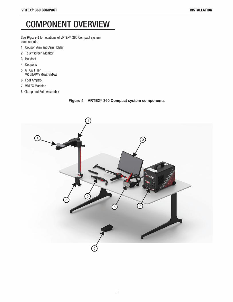
COMPONENT OVERVIEWSee Figure 4 for locations of VRTEX® 360 Compact system components.
1. Coupon Arm and Arm Holder
2. Touchscreen Monitor
3. Headset
4. Coupons
5. GTAW Filler VR GTAW/SMAW/GMAW
6. Foot Amptrol
7. VRTEX Machine
8. Clamp and Pole Assembly
Figure 4 – VRTEX® 360 Compact system components
6
1
4 2
5
3 7
8

10
INSTALLATIONVRTEX® 360 COMPACT
HARDWARE SPECIFICS
VR GMAW/FCAW GUN
The VR gun has a trigger that is used during the simulation of GMAW and FCAW processes to initiate and maintain the simulated welding arc.
VR SMAW DEVICE
The VR SMAW device has a rod that represents a stick electrode. This rod retracts when a virtual arc is struck to simulate the electrode burning off during the virtual welding process. When the virtual electrode burns down to a stub, the rod will stop retracting and the user will no longer be able to weld. When the user presses “new stick” in the orange actions and cues menu icon, the rod extends out, simulating that a new electrode was put into the VR SMAW device.
In order to strike an arc with the VR SMAW device, gently strike or tap the tip of the rod (of the VR SMAW device) on the coupon being welded. To break the arc, move the VR SMAW device rod away from the work piece.
Do not try to strike the arc with excessive force, as the arc start is distance based. Excessive force may result in damage to the VR SMAW device.
The angle of the rod can be changed by squeezing the handle of the VR SMAW device. This allows the rod to be moved into the 45 or 90 degree position. Once the rod is at one of these angles, release the handle. The rod should now be fixed in that position. Do not change the rod angle while the rod is extending or retracting.
VR GTAW TORCH AND FILLER
The VR GTAW torch also includes a footpedal that is used during the simulation of GTAW processes to initiate and maintain the simulated welding arc. Also note the LASER screen will evaluate both the GTAW torch and filler. The welding arc can be initiated by the footpedal, hand amptrol or lift start.
Figure 5 – VR GMAW/FCAW gun
CAUTION
Figure 6 – VR SMAW device
Figure 7 – VR GTAW torch and filler

11
INSTALLATIONVRTEX® 360 COMPACT
HEADSET
HEAD SIZE ADJUSTMENT: To adjust the headset size, loosen the straps on the sides and top. Put on the headset starting with the back strap then move the front display down over the eyes. Hold the display and adjust the straps until snug. The opposite applies to users with eyeglasses. Place headset over glasses and face and then push strap over back of head.
EARPHONES: Adjust the earphones to fit over the ears. Volume can be changed in the software.
COUPONS
The coupons represent the various workpieces on which the user can virtually weld. During the virtual welding process, they provide physical feedback to the student.
There are seven VR Coupons:1. Flat Plate2. T-Joint3. V Groove4. 2” Pipe XXS5. 6” Pipe Schedule 406. Lap Joint7. Pipe On Plate
The coupons along with all VR devices have been factory calibrated by The Lincoln Electric Company.
Figure 8 – Headset components
4
5
6 23
1
7
Figure 9 – VR Coupons
EARPHONES
ADJUSTMENTSTRAPS

STAND ASSEMBLY
The Stand Assembly is comprised of the Clamp and Pole Assembly, Arm Holder, Coupon Arm, two Pivot Lock Pins and a Collar Pin. The Clamp and Pole Assembly should be securely affixed to work space surface before use.
ARM HOLDER
The Arm Holder slides up and down the pole and rest on the Collar Pin. The Coupon Arm is placed in the Arm Holder and locked in position with the two Pivot Lock Pins. The arm can be placed in six different positions dependent on desired weld.
POLE
Hole numbers 1 through 9 indicate position of welding for program accuracy. The position that the Coupon Arm is located is read by identifying the numbered hole that the Collar Pin has been inserted into. The angle of the arm can be adjusted by turning the Pole Position Lock Knob counter-clockwise to loosen tension on the pole, moving the arm to desired location and turning the knob clockwise to again tighten.
CURRICULUM FLASH DRIVE
The Curriculum USB Flash Drive* contains the following files:
• M Manual
• Welding Guide (WPS)
• Curriculum Pages
• Warranty Information
* Subject to change by marketing.
12
INSTALLATIONVRTEX® 360 COMPACT
Figure 10 – Welding Positions
Figure 11 – Pole Lock Position

13
INSTALLATIONVRTEX® 360 COMPACT
HARDWARE UNCRATING1. “MACHINE SKID” – Using a utility knife, carefully remove the
two plastic bands securing the carton to the skid. See Figure 12.
2. Open carton flaps and remove all packaging material.
3. Remove the top layer of boxes (“DEVICE / COMPONENTS”, “HEADSET (HMD)” and “SMAW”) and the “MONITOR” box.
4. Carefully lift the carton off the skid.
5. Remove the remaining boxes from the skid.
SETUP PROCEDURE
Route all cables in a safe manner to avoid any tripping hazards.
1. “MACHINE BOX” – Remove the VRTEX® 360 Compact machine from the box and place on desired work space.
2. Remove the nylon cable tie securing the headset cable.
3. “MONITOR BOX” – Remove the monitor from the box and place on desired work space. Save the monitor manual for reference. Save the provided microfiber cloth for cleaning of the monitor screen.
4. If desired, remove the protective screen covering. (Monitor can be used with screen covering in place). NOTE: Optimal monitor settings have been adjusted at the factory. No setup required.
5. “DEVICE / COMPONENTS BOX” – Remove the monitor cable assembly from the box.
6. Carefully lay the monitor on its back. Lift the stand away from the body and connect the correct end of the monitor cable to the corresponding connections on the monitor. See Figure 13.
7. Once connected, place monitor upright. Route the cables between the stand and body of monitor ensuring the monitor and stand are sitting directly on work surface.
8. Connect the other end of the monitor cable to the corresponding connections on the back of the machine. See Figure 14.
9. “DEVICE / COMPONENTS BOX” – Remove the remaining contents from box and place on desired work space.
10. “SMAW DEVICE BOX” – Remove the contents from box. Remove the nylon cable tie securing the cable to the device. Place the device on desired work space.
11. “HEADSET (HMD) ASSEMBLY BOX” – Remove the contents from box and place on desired work space.
12. Connect the Headset (HMD) to the machine’s HMD cable. See Figure 15.
CAUTION
Figure 12 – Machine Skid
Figure 13- Monitor connections
Figure 14- Monitor connections

14
INSTALLATIONVRTEX® 360 COMPACT
13. Remove the Headset Latch and USB Clamp from the literature package bag. Save the HMD manuals for reference.
14. Install the latch and clamp on the headset connections. See Figure 16.
15. “STAND ASSEMBLY BOX” – Remove the three boxes.
16. “CLAMP AND POLE ASSEMBLY” – Remove the contents from box. Install assembly on work space surface. Tighten clamp knob as necessary to ensure assembly is solidly affixed to work space surface.
Failure to solidly affix Clamp and Pole Assembly to work space surface can result in injury to user and/or damage to product.
NOTE: Dependent on the work space surface thickness, it may be necessary to adjust the overall opening of the clamp. This can be accomplished by removing the two screws with the supplied Allen Wrench and repositioning as needed.
17. “ARM HOLDER” – Remove contents from box.
CAUTION
Figure 15 – Headset connections
Figure 16 – Headset connections
Figure 17 – Stand assembly box
Figure 18 – Clamp adjustment
Figure 19 – Arm holder

15
INSTALLATIONVRTEX® 360 COMPACT
18. Install Arm Holder by placing over pole and sliding down to just above desired height. Partially insert Collar Pin into corresponding hole. Simultaneously move the Arm Holder down while further inserting the pin until the Arm Holder is resting on the Collar Pin and the tip of the pin is inserted into the Arm Holder through hole. See Figure 20.
19. “COUPON ARM” – Remove contents from box. Remove nylon cable tie securing cable to arm. Install Coupon Arm into Arm Holder using the two Pivot Lock Pins. See Figures 21 and 22.
20. Connect the Coupon Arm cable to the back of the machine. See Figure 23.
21. Connect Power Cord to back of machine. Place fused Power Input Module rocker switch in the “I” (On) position. See Figure 24.
NOTE: Surge protector (or surge suppressor) may be used to protect the electronic components of the machine from input power surges.
Figure 20 – Arm holder
Figure 21 – Coupon arm
Figure 22 – Coupon arm
Figure 23 – Coupon arm cable
Figure 24 – Power Input Module rocker switch

16
INSTALLATIONVRTEX® 360 COMPACT
22. Connect the desired welding device to the corresponding connectors on the front of the machine. See Figure 25.
23. Carefully secure the desired welding coupon to the coupon arm. See Figure 26.
24. The weld simulation can be broadcast on an external display by using the External Monitor HDMI connection. See Figure 27.
NOTE: The ethernet port on the back of the machine is for future development. Do not connect anything to this connection at this time.
Figure 25 – Welding machine connectors
Figure 26 – Welding coupon
Figure 27 – Welding coupon
DEVICE LABELSThe devices for each VRTEX machine are calibrated for optimal performance. It is not recommended to swap a device between machines because the device may not appear properly in the virtual environment.
Each device is labeled with a “Tool Ref No.” This number appears on the front (or each side) of the VRTEX machine. The user should ensure the number on the device matches the number on the machine.

17
OPERATIONVRTEX® 360 COMPACT
POWERING ON* Ensure coupon arm cable and intended welding devices are
connected before turning on the machine.
1. Pressing the power button on the front of the machine powers up the VRTEX system. See Figure 28.
NOTE: Select Log Out and Shutdown from the red menu icon to turn off the system. Pressing the power button will also shutdown the system.
NOTE: Main power disconnect located in the rear of the machine.
LICENSE AGREEMENTThe License Agreement is an agreement to the terms and conditions on which Lincoln Electric grants to the business entity registered with Lincoln on the purchase of the Software (“Software Licensee”), a non-exclusive license to use the Software and Documentation accompanying this license on the VRTEX Virtual Reality Welding Trainer. The license granted herein is strictly limited to the installation of said Software on the VRTEX Virtual Reality Welding Trainer that the Licensee has properly registered with Lincoln.
This is the first screen that will appear once the Software upgrade has been accomplished. In past upgrades the system would move directly into the License page of the Instructors mode. This upgrade the user must agree to the terms and conditions before moving forward.
SELECTING AGREE OR DO NOT AGREE
Once the user has completely read the EULA select the “I have read the EULA and agreed to its terms” and move forward or select “I do not agree” which will turn off the machine. Selecting the “I have read the EULA and agreed to its terms” will take the user to the “License” screen.
NOTE: The user cannot continue on the VRTEX until they AGREE to the License Agreement.
WELDING / CUTTING SELECTION SCREEN
Welding and cutting are available with the VRTEX. The user can select either at startup. To enable Cutting contact a Lincoln Electric representation.
Figure 28 – Power button
Select the iconto choose “Ihave read theEULA andagree to itsterms.”
Figure 29 – End user license agreement (EULA)
Figure 30 – Welding / cutting selection screen

18
OPERATION (USER MODE)VRTEX® 360 COMPACT
USER MODE
SYSTEM SETUP INFORMATION
When setting up the virtual equipment, the user must set the welding parameters (e.g. wire feed speed for VR GMAW) within the ranges set in the tolerance editor. The system ships with Lincoln default tolerances. Lincoln default tolerances can be reviewed in the tolerance editor or in the WPS manual.
However, instructors can set and use their own tolerances and control limits for teaching welders. The tolerances also determine how the user is scored on such parameters as work angle, travel angle, travel speed, position and contact tip to work distance or arc length. See the Tolerance Editor section for more details.
LOGIN SCREEN
OVERVIEW
This page allows the user to: (See Figure 31)
• Enter Username
• Select Language Preference (Orange Icon)
• Select Imperial or Metric Units (Blue Icon) - See Table 1 for details
• Shutdown System (Red Icon)
• Continue to the next Setup Screen (Green Icon)
• Select Theory (Yellow Icon)
Figure 31 – Login screen
MEASUREMENT UNITS Imperial Metric
Abbrev. Details Abbrev. Details
Coupon Thickness in. inches mm millimeters
Gas Flow Rate CFM cubic feet per minute LPM liters per minute
Wire Feed Speed IPM inches per minute MPM meters per minute
Weldometer - Base Metal lbs pounds kg kilograms
Weldometer - Gas CF cubic feet L liters
Weldometer - Consumables lbs pounds kg kilograms
Table 1 – Measurement units

19
OPERATION (USER MODE)VRTEX® 360 COMPACT
1. USB Indicator
The circular USB icon in the upper right corner of the screen indicates the presence of a USB memory stick in the front of the machine. Translucent: no USB stick connected, Green: USB connected and ready.
2. Theory Screen
The theory icon has been implemented to assist users with additional content, images and information related to the area of the application where you are working. See Figure 32. This information can be accessed by selecting the yellow theory icon. When selected, the icon allows the student to access visual and definitional information about the different welding terms being used on each screen. Welding terms that correspond with each page are listed in the boxes on the left-hand side of the screen. When finished reviewing the theory data, the student can select the theory icon again to exit the screen.
COUPON CONFIGURATION SELECTION SCREEN
OVERVIEW
The user selects which coupon configuration they want to virtually weld. (Red arrows change material type). See Figure 33.
PROCESS SELECTION SCREEN
OVERVIEW
This screen allows the user to select the welding processes. See Figure 34. To change among GMAW, FCAW, SMAW, and GTAW, the user touches the desired processes. If a process is not supported for the selected material/thickness, it will not appear on this screen and cannot be selected. To choose among different sub-processes, touch the appropriate icon.
At the top of the screen, the user can see the coupon position and thickness selected. As the user continues to set up the simulation, additional information will be added to the right of this readout so that the user can reference what has previously been selected.
TABLE SETUP SCREENSOVERVIEW
The correct VR table information must be selected for the VRTEX to operate properly in all virtual welding applications. See Figure 35. After entering the table setup information and selecting the green continue icon, the screen will display a representation of the pole setup and the status of the necessary connected devices. A green checkmark will indicate a properly connected device and a red X will indicate a disconnected device. See Figures 36 and 37.
Figure 32 – Theory screen
Figure 33 – Joint configuration screen
Figure 34 – Process selection screen
Figure 35 – Table setup screen

20
OPERATION (USER MODE)VRTEX® 360 COMPACT
COUPON INSERTION
Insert the VR coupon into the desired position in the VR table. See Figure 38. Make sure the coupon is fully seated into the track and then lock the coupon in place by pushing in the knob at the end of the arm. To release, pull the knob into the unlocked position and remove the coupon. When the system is in use, the coupon should always be locked in place to assure system accuracy.
Position coupon stand at least eighteen inches from monitor and any potential source of electrical and magnetic interference.
ENVIRONMENT SCREEN
OVERVIEW
The VRTEX comes pre-configured with a number of different virtual welding environments. To select an environment, touch the desired icon. See Figure 39.
When welding in virtual reality be mindful of your real world surroundings and hazards at all times to avoid injury.
Figure 37 – Table setup & device status screen (showing all needed devices are connected)
Figure 36 – Table setup & device status screen (showing SMAW device needed but not connected)
Figure 38 – VR coupon (unlocked position)
CAUTION
CAUTION
Figure 39 – Environment screen

21
OPERATION (USER MODE)VRTEX® 360 COMPACT
PARAMETER SETUP SCREEN
OVERVIEW
On this screen, the user selects the welding parameters. See Figures 40 and 41. The welding parameters must be entered according to the tolerance editor.
If default tolerances are being used, refer to the WPS manual.
Once the user has set the welding parameters, select the green check settings icon. If the user has entered any settings outside the acceptable range, the incorrect weld setting screen will appear and will not allow the user to proceed. Once the settings are correct, the program will enter the virtual environment.
Figure 40 – Gas selection screen
Figure 41 – Polarity selector screen

22
OPERATION (USER MODE)VRTEX® 360 COMPACT
VIRTUAL WELDING OVERVIEW
While a user is welding, observers can see the welder’s view, Live Action Student Evaluation Report (LASER) screen or instructor’s view displayed on the monitor. See Figure 42. The welder’s view shows what the user with the headset on is seeing through the headset. The Live Action Student Evaluation Report (LASER) screen displays a real time graph of the weld being made and gives a score when the user selects “end pass”. The instructor’s view allows another user to zoom in/out, pan and rotate the coupon to view the weldment from different angles in real time. Use the white “Next” or “Prev” arrows to select different views.
UPPER OVERLAYS
The welding technique set in the tolerance editor and other process details are displayed on the upper right portion of the screen.
ORANGE ACTION AND CUES ICON
The orange action menu icon has the following options:
• Travel Speed
• AIM
• Travel/Work Angles
• CTWD (Contact To Work Distance)
• Arc Length
• Postflow
• Filler Movement
• Filler Dip Frequency
• Weave
• Whip
Only available cues will appear (based on welding process).
VISUAL CUESVisual cues are aids to help users learn faster. The travel speed, CTWD, arc length and travel/work angle cues indicate whether the user is within the tolerances set in the tolerances editor. Generally, these cues are color coded as well as symbolic. When cues are red, they indicate being out of tolerance. Yellow cues indicate close to tolerance, but not optimal. Green cues indicate being within tolerance and close to optimal.
The “Cheater” Lens magnifies the image as seen by the user in the headset and in the welder’s view. The user can toggle between Off, 1.25X, 1.5X, 1.75X, 2X select their option with the red select icon.
Travel Speed turns on the travel speed visual cue. See Figure 43. This cue uses the color coding position to indicate travel speed.
NOTE: The goal is to keep the arrow in the center of the graph which will also keep it green.
The CTWD (Contact Tip To Work Distance) cue uses color and position to indicate proper CTWD. See Figure 44. The goal is to get the tip of the green arrow on the line of the “H” bar and keep the arrow color green (also known as Arc Length).
Figure 42 – User screen view
Figure 43 – Travel speed
Figure 44 – CTWD (contact tip to work distance)

23
OPERATION (USER MODE)VRTEX® 360 COMPACT
The Travel/Work Angle cue can be used with the SMAW, GMAW, GTAW or FCAW processes. See Figure 45. The goal of this cue is to center the circle in the cross hair and keep the color green.
The Aim cue can be used with the SMAW, GMAW, GTAW or FCAW processes. See Figure 46. The goal of this cue is to position the VR GMAW/FCAW Gun or VR SMAW device so the aim cue is a thin green line. This indicates that the weld is being made in the correct location or position.
The Whip cue helps the student use correct spacing between whipping motions, puddle time and whip time. Correct whipping technique is indicated by a green outer ring (spacing) with a green center (puddle and whip timing).
The Weave cue can be used to space the weave so the outer ring is green (good weave spacing), set the width of the weave so line is green (good weave width) and a green filled ring (good dwell time on the toes of the previous weld).
GTAW CUESGTAW can either be done with or without filler metal. Several customized cues have been created for the GTAW process.
FILLER DIP FREQUENCY
1. When the Rhythm Guide is at its smallest, put filler into puddle. See Figure 49.
2. When the Rhythm Guide is at its largest, remove filler from puddle. See Figure 49.
FILLER MOVEMENT-
1. Position the Filler so the Position Cue matches to contours of the Aim Guide. See Figure 50.
2. The Aim Tether shows the distance disparity between the Aim Cue and Aim Guide. See Figure 50.
3. The Dip Cue, Position Cue and Aim Tether are green when adding filler to the correct location of the puddle. See Figure 50.
4. The Dip Cue, Position Cue and Aim Tether are yellow/red when adding filler to the incorrect location of the puddle. See Figure 50.
Figure 45 – Travel/work angle
Figure 46 – Aim
Figure 47 – Whip
Figure 48 – Weave
Figure 49 – Filler Dip Frequency

24
OPERATION (USER MODE)VRTEX® 360 COMPACT
AMPERAGE
1. The footpedal location matches the real life movement of the amperage controller. See Figure 51.
2. Move the footpedal so the location falls within the green ideal zone. See Figure 51.
3. On Aluminum weld the ideal amperage range changes the longer you are welding to compensate for heating of the aluminum part. See Figure 51.
POSTFLOW
1. Only appears after breaking the arc. See Figure 52.
2. Maintain correct aim and arc length to keep both cues green. See Figure 52.
3. Wait for the second hand to do a full cycle back to the 12 o’clock position. See Figure 52.
4. If Arc length or Aim goes out of bounds then the post flow is failed. See Figure 52.
NEW COUPON
Selecting the blue new coupon menu icon replaces the current coupon with an unwelded coupon. Note that this is a quick way to start over on the same configuration and process but that it will remove all passes from the coupon and the graphs on the LASER screen. Selecting “New Coupon” will also save the previous weld to a USB stick (if attached).
WHITE SELECT ARROWS (BUTTON ICON)
Touching the white select arrows allow the user to rotate through the monitors’ LASER screen, instructor’s view and welder’s view.
WELDER’S VIEW SCREEN
This screen shows the virtual view as seen by the user wearing the headset.
INSTRUCTOR’S VIEW SCREEN
This screen shows the coupon and virtual weld in real time. See Figure 53. An observer can rotate, pan and/or zoom in or out on the coupon. This view also shows the device being used.
NOTE: Changing views on the monitor does not change the user’s view in the headset.
Figure 51 – Amperage
Figure 50 – Filler movement
Figure 53 – Instructors view
Figure 52 – Postflow

25
OPERATION (USER MODE)VRTEX® 360 COMPACT
END PASS
When the user selects the green “End Pass” menu icon, the pass is scored, a snapshot of the weld is taken and the percentages of the weld containing discontinuities are calculated. If the user has inserted a USB device, selecting “End Pass” also automatically saves a student report to the USB memory device at the front of the weld machine.
LASER SCREEN(Live Action Student Evaluation Report)
OVERVIEW
This screen summarizes the student’s welding performance. Detailed information about the student’s welding technique for each pass are displayed on this screen. See Figure 54.
TECHNIQUE PARAMETERSThe upper right area of the screen shows the technique parameters being tracked and the graph of these parameters is located to the left. See Figure 54. When the user welds, each parameter is graphed using a line that is of the same color as the technique parameter box. For example, “position” is written in the blue box and indicated by the blue line. The left side of the graph represents the left side of the coupon and the right side represents the right side of the coupon. For vertical welds, the graph is rotated so that it is vertical, with the bottom representing the bottom of the coupon and the top repre-senting the top of the coupon. The graph also shows how close the parameter was to the ideal value. The ideal value is indicated by the red line located in the center of the graph. This value is determined by the tolerance editor settings. The upper and lower white lines represent the acceptable maximum and minimum values that the parameter should be within. These values are also determined by the tolerance editor setting. Anything above the top white line or below the bottom white line is out of tolerance. The closer the user is to the ideal line, the better the weld. Each parameter can be toggled on or off of the graph by touching the appropriate icon.
WELD EVALUATIONGRAPH
Figure 54 – Laser screen (graph, defects, discontinuities, etc.)

26
OPERATION (USER MODE)VRTEX® 360 COMPACT
Position is the user’s ideal weld root location. This location can change with each pass. When weaving, the ideal location is considered the centerline of the weave.
Contact Tip to Work Distance (CTWD) and Arc Length are the distances from the tip of the VR GMAW/FCAW gun or VR SMAW device to a plane going through the ideal position location. See Figures 55 and 56.
Work Angle is the angle between the electrode and workpiece as seen in Figure 57.
Travel Angle is the angle between the electrode and the workpiece in the direction of travel. See Figure 58. The upper right area of the screen displays if the user should be pushing or dragging. If the user pushes when they should be dragging, they will not receive maximum points. For pipe welding, this is the angle between the electrode and the tangent of the pipe at that point.
Travel Speed is how fast the electrode is traveling in respect to the workpiece.
Dime Spacing is the distance from one solidified weld puddle to the next (whip technique only).
Whip Time is the time the user is in the whipping motion or not dwelling in the weld puddle (whip technique only).
Puddle Time is the time the user is dwelling or keeping the device in the virtual puddle (whip technique only).
Width of Weave is the side-to-side distance of where the device was aimed when completing one weave cycle in a series that make up a weld (weave technique only).
Weave Timing is the time taken to complete one side to side weaving motion (weave technique only).
Weave Spacing is the distance in the overall direction of travel between one weave cycle in a series that make up a weld (weave technique only).
PASS NUMBERThe pass number is displayed on the top left corner of the screen. To change the pass being viewed on the LASER scoring screen, touch the arrow icons.
TRAVEL DIRECTIONThe travel direction is located on the left side in the middle of the screen. When the user first starts to weld, a travel direction is sensed by the system and an arrow indicating the direction is displayed. For visual cues, the system assumes these directions. The visual cues will automatically adapt to the travel direction used when the arc is struck.
Figure 55 – Contact tip to workdistance (CTWD)
Figure 56 – Arc length
Figure 57 – Work angle
Figure 58 – Travel angle

27
OPERATION (USER MODE)VRTEX® 360 COMPACT
BEAD RENDERAn image of the completed pass appears in the middle of the screen.
DISCONTINUITY INDICATOR
The lower right side of the screen list potential discontinuities. See Figure 59. When a student uses incorrect welding techniques, this causes specific weld discontinuities. A line is drawn at the location indicating these discontinuities. For example, too long an arc length will cause porosity.
Potential discontinuities include:
• Porosity
• Concave/Underfill
• Convex/Excessive Reinforcement
• Undercut
• Incomplete Fusion/Penetration
• Excess Spatter
• Wrong Weld Size
• Poor Bead Placement
• Melt Through / Blow Through
• Slag Inclusion
• Dross
• Burn Back
• Tungsten Inclusion
• Tungsten Contamination
SCOREA score for each parameter is calculated. The closer each parameter is to the ideal value, the higher the score will be (out of 100). The total score of the scoring section is calculated as an average of all parameters. To achieve the maximum score, the weld must be made on the entire length of the coupon. When all of the passes have been completed and scored, an average for all of the passes will appear.
STUDENT REPORTThe student report is a PDF file that captures the graph, disconti-nuities, bead render, score and other information about the weld. See Figure 60. This PDF file can be printed or archived from another computer to track student progress. Example of PDF below shows student’s record.
Figure 59 – Potential discontinuities
Figure 60 – Student report

28
OPERATION (INSTRUCTOR MODE)VRTEX® 360 COMPACT
INSTRUCTOR MODE AND ADMIN ACCESS
TO ENTER INSTRUCTOR MODE
1. Touch the “Key” icon located in the lower left corner of the screen. See Figure 61.
2. The default password is 1,2,3,4,5. To change the password, use the icon with the key and + sign. See Figure 62.
The instructor mode includes the following: See Figure 63.• Weldometer • Update
• Tolerances • Options
• Scoring Modules • License Info
Figure 61 – Menu and instruction key
Figure 62 – Instruction entry menu
Figure 63 – Instructors mode screen

29
OPERATION (INSTRUCTOR MODE)VRTEX® 360 COMPACT
WELDOMETER
OVERVIEW
The Weldometer tracks virtual consumables, arc time, base material and gas usage. This information can be used to track materials and cost savings incurred by the use of virtual welding training. The Weldometer tracks material usage and arc time over a “trip” (since last reset) and over the VR system’s lifetime. See Figure 64.
Arc Time keeps track of the amount of time (hours:min:seconds) students have a virtual arc struck with each process.
Base Metal tracks metal type and how many virtual coupons have been used and their cumulative weight. Base metal screens are separated by metal type for Mild Steel, Aluminum and Stainless Steel.
Gas tracks how much virtual gas has been used.
Consumables tracks the cumulative weight of each type of virtual consumable used. It also displays how many virtual SMAW electrodes are used.
At the bottom of the screen, the Simulated Welder Time keeps track of how long the unit has been on (time in hours:minutes:seconds).
RESET TRIP
Selecting Reset Trip zeroes out all items in the trip column. This allows an instructor to track VR material savings over a certain time period.
SAVE TO FILE
If a USB memory device is inserted in the unit, selecting “save to file” saves a file with all of the current Weldometer information in a text format. Once the file has saved, the user can take the USB to a computer or printer to print, email, copy, store or view the file.
Figure 64 – Weldometer

30
OPERATION (INSTRUCTOR MODE)VRTEX® 360 COMPACT
TOLERANCE EDITOR OVERVIEW
The tolerance editor allows users to modify the system settings from the default to fit their curriculum. See Figure 65.
The VRTEX ships with Lincoln “default” welding parameters pre-in-stalled. New parameters can be created by the instructor to reflect a specific welding application or technique.
NOTE: Default parameters cannot be modified.
This tolerance editor affects the file currently being shown in the “choose tolerance setup” window.
Selecting Create New creates a new file on the unit. The file starts with the default settings. Selecting this icon takes the user to a keyboard screen so that a new file name can be entered.
Selecting Rename brings the user to a keyboard screen where the name of the current file can be changed.
Selecting Copy makes a copy of the file currently being shown on the choose tolerance setup window. The copy is identified with the same name plus an incremented number after it.
Selecting Save to USB saves the current file to a USB memory device, if a USB memory device is inserted in the front of the machine.
Selecting Customize allows the instructor to adjust various tolerances to the desired level.
Selecting Delete erases the file currently shown.
Changing the settings in the tolerance editor will dramatically affect how the system runs, including scoring, visual cues and discontinuities. Take care in changing the settings of the tolerance editor as not to reflect unrealistic welding situations.
CHOOSE TOLERANCE SETUP
Displays the list of all tolerance settings currently stored on the unit. All units ship with default settings and learning levels. If the user creates multiple tolerance files, the file in use is selected by using the red arrow icons. This affects the visual cues, graphs, discontinuities and score. The current tolerance settings in use are also listed on this screen.
CHOOSE TOLERANCE TO LOAD
This displays the list of all tolerance sets currently stored on the USB device. Files can be transferred to and from a VRTEX with a USB memory device.
Load from USB: Transfers files from USB to VRTEX.
Copy to List: Copies the folder from the chosen tolerance to load box and saves it to the VRTEX.
Figure 65 – Tolerances
CAUTION

31
OPERATION (INSTRUCTOR MODE)VRTEX® 360 COMPACT
CUSTOMIZE TOLERANCE LEVELS
The following steps describe the procedure to change tolerances for the VRTEX:
1. Select Tolerances.
2. Select Create New.
3. Enter a new tolerance name on the keyboard screen.
4. Select Continue.
5. Scroll through “Choose Tolerance Setup” menu to display the desired tolerance.
6. Select the Select Tolerance icon when the desired name is displayed in the field.
NOTE: When desired tolerance name is properly selected, that name will be displayed at the top of the screen next to “Current Tolerance”.
7. Select “Customize”.
8. The user selects which configuration to modify. See Figure 66.
9. The user selects which process to modify. See Figure 67.
10. The equipment settings screen allows for the modification of the following welding parameters (See Figure 68):
• Wire Feed Speed
• Amperage
• Voltage
• Polarity
11. The gas screen allows for the modification of the following welding parameters (See Figure 69):
• Gas Mixture Selected
• Gas Flow Rate
• Preflow
• Postflow
Figure 66 – Joint configuration selection screen
Figure 67 – Process selection screen
Figure 68 – Equipment settings screen
Figure 69 – Gas screen

32
OPERATION (INSTRUCTOR MODE)VRTEX® 360 COMPACT
12. The welding technique parameters screen allows the modification of (See Figure 70):
• CTWD/Arc Length
• Work Angle
• Travel Angle
NOTE: The travel angle for drag welding techniques should always be less than 90 degrees. The travel angle for pushing technique should always be greater than 90 degrees.
13. The pattern & aim screen allows the user to change the type of pattern being used (stringer, box weave, straight weave, whip, triangle weave) and the position of the root of the weld. See Figure 71. The X and Y values change the location of where the weld bead should be placed. See Figure 72. This affects the position parameter on the Live Action Student Evaluation Report (LASER) screen. The +/- determines how far off from the ideal position the student can place the electrode before it results in a misplaced weld.
Z
Y
X
XXX Z
TEE PIPE GROOVE
Figure 70 – Welding technique parameters screen
Figure 72 – Coordinate chart for weld placement (position)
Figure 71 – Pattern & aim screen

33
OPERATION (INSTRUCTOR MODE)VRTEX® 360 COMPACT
14. The whip & travel screen allows for the modification of technique parameters relating to the whipping welding technique and travel speed including (See Figure 73):
• Dime Spacing
• Whip Time
• Puddle Time
• Travel Speed
15. The weave screen allows for the modification of weaving welding technique including (See Figure 74):
• Width of Weave
• Weave Timing
• Weave Spacing
SCORING MODULESAfter welding a pass, the user can now see whether each defect/discontinuity was within acceptable standards (passed) or not (failed). The acceptable standards implemented in VRTEX are known as scoring modules. Instructors can enable the scoring module they would like to use (i.e., AWS D1.1 or ASME). The pass/fail marks will appear on the LASER screen for relevant passes (scoring modules do not cover all of the available VRTEX welds).
The SCORING MODULE feature can be used when the user wishes to have their welding evaluated against the ASME or AWS D1.1 standards. Select the SCORING MODULES icon and use the red arrows to toggle between scoring based on ASME standards, D1.1 standards, and None.
UPDATE
OVERVIEW
The update screen in the instructor mode allows the user to update their software or to update specific configuration files from the USB memory device in the front of the VRTEX. Selecting this brings up two options (See Figure 76):
• Update Software
• Update Configuration File
Figure 73 – Whip & travel screen
Figure 74 – Weave screen
Figure 75 – Scoring Modules
Figure 76 – Update

34
OPERATION (INSTRUCTOR MODE)VRTEX® 360 COMPACT
UPDATE SOFTWARE
Selecting this option loads a newer version of the software if one is available on a USB inserted in the front of the machine. Updating to a different version may shut down or restart the system.
After updating, the system may need to be shut down and restarted for changes to be implemented.
UPDATE CONFIGURATION FILE
Selecting this option loads any configuration changes from the USB inserted in the front of the machine. This is used for part replacement.
SETTINGSThe options screen, in the instructor mode, allows the user to change the volume of the user interface and welding sounds, date and time settings and sensor settings (magnetic frequency ID). See Figure 77. The options screen also allows the user to view the status of any connected devices. Selecting the yellow DEVICE STATUS icon will display the connection status of each device. Properly connected devices will display a green checkmark and improperly or not connected devices will be displayed with a red X. See Figure 78.
Figure 77 – Options
Figure 78 – Device status

ADDITIONAL FEATURESWELDING WITHOUT THE HEADGEAR
Designed to allow users the ability to weld without being totally immersed inside the virtual environment.
Users now have the option to view the welding process in the virtual reality headgear, or choose instead to use the Auto Camera and positioning on the touchscreen monitor.
To disengage the headset the user will need to follow a few simple steps.
1. Administrator Access Screen.
2. Enter the passkey code. The unchanged generic code is 1-2-3-4-5. Press the unlocked padlock.
3. Inside Administrator Access press Settings.
4. Inside settings un-check Enable VR Device. Users will be prompted to SHUTDOWN and restart. To enable the headgear follow the same steps, except this time the user will press the box to check VR Enabled.
5. Users can disconnect the helmet when not in use. It is recommended that any disconnect/connect be done with the machine power off.
35
OPERATIONVRTEX® 360 COMPACT
1
Figure 79
2 3
Figure 80
4
Figure 81
5
Figure 82
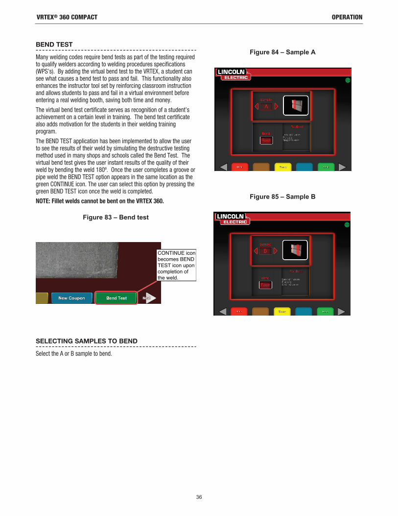
36
OPERATIONVRTEX® 360 COMPACT
BEND TEST
Many welding codes require bend tests as part of the testing required to qualify welders according to welding procedures specifications (WPS’s). By adding the virtual bend test to the VRTEX, a student can see what causes a bend test to pass and fail. This functionality also enhances the instructor tool set by reinforcing classroom instruction and allows students to pass and fail in a virtual environment before entering a real welding booth, saving both time and money.
The virtual bend test certificate serves as recognition of a student’s achievement on a certain level in training. The bend test certificate also adds motivation for the students in their welding training program.
The BEND TEST application has been implemented to allow the user to see the results of their weld by simulating the destructive testing method used in many shops and schools called the Bend Test. The virtual bend test gives the user instant results of the quality of their weld by bending the weld 180º. Once the user completes a groove or pipe weld the BEND TEST option appears in the same location as the green CONTINUE icon. The user can select this option by pressing the green BEND TEST icon once the weld is completed.
NOTE: Fillet welds cannot be bent on the VRTEX 360.
SELECTING SAMPLES TO BEND
Select the A or B sample to bend.
CONTINUE iconbecomes BENDTEST icon uponcompletion ofthe weld.
Figure 83 – Bend test
Figure 84 – Sample A
Figure 85 – Sample B

37
OPERATIONVRTEX® 360 COMPACT
SELECTING ROOT OR FACE
Select the direction of the bend to the ROOT or FACE. Once the desired sample is chosen, press the green BEND icon to begin the bend test.
Once the first sample has been bent, use the white NEXT or PREV arrow to select the next tab to bend.
BEND TEST FAILURE
The VRTEX will visually inspect the weld before allowing it to be bent. If the weld passes the visual inspection, the user can proceed with the bend test. If a weld fails the bend test, the details such as a percentage of failure will be displayed in the information box on the right side of the screen. The weld failure is measured in three different aspects including Lack of Fusion, Porosity, and Slag Inclusion. If the user fails the bend test there will not be a virtual bend test certificate in the student report.
Figure 86 – Root
Figure 87 – Face
Figure 88 – Green to bend
Figure 89 – Completed bend test
Figure 90 – Failed
Figure 91 – Completed bend test

38
OPERATIONVRTEX® 360 COMPACT
THE CERTIFICATE
The BEND TEST CERTIFICATE is located in the STUDENT REPORT, which can be saved and accessed if there is a USB memory device in the USB slot on the front of the VRTEX while performing the virtual bend test procedure.
SCORING MODULES - EVALUATE AGAINST ASME / AWS D1.1
The SCORING MODULE feature can be used when the user wishes to have their welding evaluated against the ASME or AWS D1.1 standards. This option can be selected by entering the INSTRUCTORS MODE. The only screen the Instructors Mode can be accessed from is the Sign In screen. Select the SCORING MODULE located at the bottom right corner of the Instructors Mode screen. Toggle between Based on ASME Standards, Based on D1.1 Standards, and None. Press the orange BACK icon twice to return to the Sign In screen.
ALUMINUM WELDING SIMULATION
The Aluminum GMAW feature in your VRTEX allows the system to simulate the look, sound, discontinuities, equipment settings and Theory definitions for the Aluminum GMAW process. Aluminum GMAW simulates Pulse and Spray welding on tee joints (2F and 3F) and groove (1G, 2G and 3G) on 3/8” and 10 gage material. The electrode of choice for this training is the SuperGlaze™ 4043 electrode and the base material is 6061 grade aluminum.
STAINLESS STEEL WELDING SIMULATION
The Stainless GMAW feature in your VRTEX allows the system to simulate the look, sound, discontinuities, equipment settings and Theory definitions for Stainless GMAW. Stainless GMAW simulates Pulse and Spray welding on tee joints (2F and 3F) and groove (1G and 3G). For more information on how to operate the Stainless GMAW feature, visit: www.vrtex.com for the latest instruction manual. The electrode of choice for this training is the Blue Max™ 308L Si electrode and the base material is 308 grade stainless steel.
REPLAY MODE
The Video Replay feature in your VRTEX provides the ability to view your virtual weld video once you have completed it. This feature offers students and instructors the ability to refine skills by replaying the weld performed from the different viewing angles and discussing technique.
DEMO WELD MODE
The Demo Weld feature in your VRTEX provides an example of the virtual weld you have selected. By selecting and viewing this virtual weld, you can see the suggested technique on how to successfully make the chosen weld.
Figure 92 – Bend test certificateFigure 93 – Replay mode
Figure 94
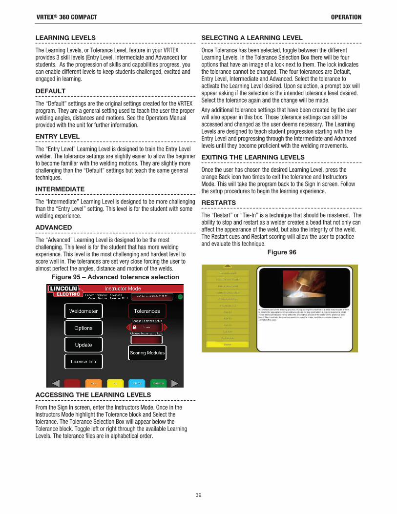
39
OPERATIONVRTEX® 360 COMPACT
LEARNING LEVELS
The Learning Levels, or Tolerance Level, feature in your VRTEX provides 3 skill levels (Entry Level, Intermediate and Advanced) for students. As the progression of skills and capabilities progress, you can enable different levels to keep students challenged, excited and engaged in learning.
DEFAULT
The “Default” settings are the original settings created for the VRTEX program. They are a general setting used to teach the user the proper welding angles, distances and motions. See the Operators Manual provided with the unit for further information.
ENTRY LEVEL
The “Entry Level” Learning Level is designed to train the Entry Level welder. The tolerance settings are slightly easier to allow the beginner to become familiar with the welding motions. They are slightly more challenging than the “Default” settings but teach the same general techniques.
INTERMEDIATE
The “Intermediate” Learning Level is designed to be more challenging than the “Entry Level” setting. This level is for the student with some welding experience.
ADVANCED
The “Advanced” Learning Level is designed to be the most challenging. This level is for the student that has more welding experience. This level is the most challenging and hardest level to score well in. The tolerances are set very close forcing the user to almost perfect the angles, distance and motion of the welds.
ACCESSING THE LEARNING LEVELS
From the Sign In screen, enter the Instructors Mode. Once in the Instructors Mode highlight the Tolerance block and Select the tolerance. The Tolerance Selection Box will appear below the Tolerance block. Toggle left or right through the available Learning Levels. The tolerance files are in alphabetical order.
SELECTING A LEARNING LEVEL
Once Tolerance has been selected, toggle between the different Learning Levels. In the Tolerance Selection Box there will be four options that have an image of a lock next to them. The lock indicates the tolerance cannot be changed. The four tolerances are Default, Entry Level, Intermediate and Advanced. Select the tolerance to activate the Learning Level desired. Upon selection, a prompt box will appear asking if the selection is the intended tolerance level desired. Select the tolerance again and the change will be made.
Any additional tolerance settings that have been created by the user will also appear in this box. Those tolerance settings can still be accessed and changed as the user deems necessary. The Learning Levels are designed to teach student progression starting with the Entry Level and progressing through the Intermediate and Advanced levels until they become proficient with the welding movements.
EXITING THE LEARNING LEVELS
Once the user has chosen the desired Learning Level, press the orange Back icon two times to exit the tolerance and Instructors Mode. This will take the program back to the Sign In screen. Follow the setup procedures to begin the learning experience.
RESTARTS
The “Restart” or “Tie-In” is a technique that should be mastered. The ability to stop and restart as a welder creates a bead that not only can affect the appearance of the weld, but also the integrity of the weld. The Restart cues and Restart scoring will allow the user to practice and evaluate this technique.
Figure 95 – Advanced tolerance selection
Figure 96
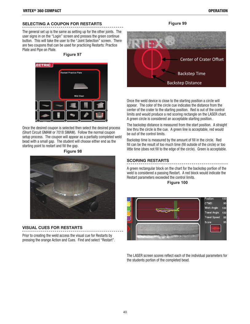
40
OPERATIONVRTEX® 360 COMPACT
SELECTING A COUPON FOR RESTARTS
The general set up is the same as setting up for the other joints. The user signs in on the “Login” screen and presses the green continue button. This will take the user to the “Joint Selection” screen. There are two coupons that can be used for practicing Restarts: Practice Plate and Pipe on Plate.
Once the desired coupon is selected then select the desired process (Short Circuit GMAW or 7018 SMAW). Follow the normal coupon setup process. The coupon will appear as a partially completed weld bead with a small gap. The student will choose either end as the starting point to restart and fill the gap.
VISUAL CUES FOR RESTARTS
Prior to creating the weld access the visual cue for Restarts by pressing the orange Action and Cues. Find and select “Restart”.
Once the weld device is close to the starting position a circle will appear. The color of the circle cue indicates the distance from the center of the crater to the starting position. Red is out of the control limits and would produce a red scoring rectangle on the LASER chart. A green circle is considered an acceptable starting position.
The backstep distance is measured from the start position. A straight line thru the circle is the cue. A green line is acceptable, red would be out of the control limits.
Backstep time is measured by the amount of fill in the circle. Red fill can be the result of too much time (fill outside of the circle) or too little time (does not fill to the edge of the circle). Green is acceptable.
SCORING RESTARTS
A green rectangular block on the chart for the backstep portion of the weld is considered a passing Restart. A red block would indicate the Restart parameters exceeded the control limits.
The LASER screen scores reflect each of the individual parameters for the students portion of the completed bead.
Figure 97
Figure 98
Figure 99
Figure 100

41
MAINTENANCEVRTEX® 360 COMPACT
CLEANING & MAINTENANCE
ROUTINE MAINTENANCE
Routine maintenance on the VRTEX should be performed on an as needed basis dependent on machine usage and environment. The coupons should be cleaned with a soft cloth if they become dusty or dirty. Inspect cables for cracks or other heat related issues, replace as necessary.
HEADSET
Taking proper care of the headset is important for optimal functioning of the equipment. Occasionally, the headset lens should be wiped with the lint free lens wipe that is provided. This can be done to remove fingerprints from the lenses. You can also use a lens cloth (e.g., from a camera shop). Paper towels or household cloths may scratch or damage the lenses and should not be used. Avoid exposing the headset to liquids. Cleaning solutions should not be used to clean the headset. Do not use Isopropyl alcohol or solutions containing alcohol to clean the lenses or plastic parts on the headset. You can also use a camera pressure canister to occasionally blow out dirt.
You may want to clean the inside of the headset occasionally. Be sure to do so without exposing the headset to any unacceptable materials, as explained above. It is acceptable to use an alcohol swab on the facial interface pad.
The headset should be kept in a clean and dry location out of direct sunlight. Avoid dirty or sandy environments, as these can lead to scratching of optics and damage the headset mechanical adjustments.
TOUCHSCREEN MONITOR
Use care when cleaning screen. Use only a soft dry cloth (cotton or flannel). Avoid chemicals and solvents (alcohol, benzine, acidic or alkaline solvent cleaners). Avoid granular or abrasive cleaning agents.
BATTERY
The backup batteries (two for each computer unit) are located behind the access panel on the rear of the machine. See Figures 110 and 111. The “AA” backup batteries can be accessed by using a T-30 torx nutdriver to remove the two screws and the panel. The machine must be powered ON when changing the backup batteries. The batteries should be replaced once a year. These batteries are required to keep the date and time settings and several startup parameters in the computer. If these settings are lost contact a service representative for assistance.
CAUTION
BATTERYCOMPARTMENT
BATTERIES
Figure 101
Figure 102

42
TROUBLESHOOTINGVRTEX® 360 COMPACT
If for any reason you do not understand the test procedures or are unable to perform the tests/repairs safely, contact your Local Lincoln Authorized Field Service Facility for technical troubleshooting assistance before you proceed.
CAUTION
This Troubleshooting Guide is provided to help you locate and repair possible machine malfunctions. Simply follow the three-step procedure listed below.
Step 1. LOCATE PROBLEM (SYMPTOM).Look under the column labeled “PROBLEM (SYMPTOMS)”. This column describes possible symptoms that the machine may exhibit. Find the listing that best describes the symptom that the machine is exhibiting.
Step 2. POSSIBLE CAUSE.The second column labeled “POSSIBLE CAUSE” lists the obvious external possibilities that may contribute to the machine symp-tom.
Step 3. RECOMMENDED COURSE OF ACTIONThis column provides a course of action for the Possible Cause.
If you do not understand or are unable to perform the Recommended Course of Action safely, contact your local Lincoln Authorized Field Service Facility.
HOW TO USE TROUBLESHOOTING GUIDE
Service and Repair should only be performed by Lincoln Electric Factory Trained Personnel. Unauthorized repairs per-formed on this equipment may result in danger to the technician and machine operator and will invalidate your factory warranty. For your safety and to avoid Electrical Shock, please observe all safety notes and precautions detailed through-out this manual.
__________________________________________________________________________
WARNING

CAUTION
43
TROUBLESHOOTINGVRTEX® 360 COMPACT
If for any reason you do not understand the test procedures or are unable to perform the tests/repairs safely, contact the Lincoln Electric Automation Department for technical troubleshooting assistance before you proceed. Call 1-888-935-3878.
PROBLEMS(SYMPTOMS)
POSSIBLE AREAS OFMISADJUSTMENT(S)
RECOMMENDEDCOURSE OF ACTION
The weld coupon image is a different configuration than the physical coupon.
Either the wrong coupon is on the stand or the wrong configuration has been selected.
Select the menu icon and select ‘change coupon type’. Change the software selections so that the images on the screen match the hardware you are using.
The welding device will not strike an arc. Check to make certain the coupon is positioned correctly and the student is attempting to weld the correct side of the coupon.
VR weld the other side of the VR coupon.
Make certain the VRTEX 360 logo on the VR coupon appears on the monitor and in the VR headset.
The students’ reports are not accessible. USB storage device not in front of machine. The students’ reports can only be saved via the USB port on the front of the VRTEX. Plug in a USB memory device into the front of the machine. If a USB memory stick is not plugged into the USB port or if there is no available memory on the USB stick, the students’ reports will not be saved.
When check settings is activated, the incorrect settings appear.
The settings in the Instructor Mode are incorrect.
Make sure all of the settings in the tolerance editor are correct for the process and parameters being used. Check for the acceptable ranges for the Lincoln defaults.
Observe Safety Guidelines detailed in the beginning of this manual.
TROUBLESHOOTING GUIDE
CAUTION

CAUTION
44
TROUBLESHOOTINGVRTEX® 360 COMPACT
If for any reason you do not understand the test procedures or are unable to perform the tests/repairs safely, contact the Lincoln Electric Automation Department for technical troubleshooting assistance before you proceed. Call 1-888-935-3878.
PROBLEMS(SYMPTOMS)
POSSIBLE AREAS OFMISADJUSTMENT(S)
RECOMMENDEDCOURSE OF ACTION
Previous weld pass data is not accessible on the LASER screen.
“End Pass” must be activated before starting a new pass. If a new coupon is started the data will only be available for the first pass. Again; “End Pass” must be selected before a new pass is started.
Use the touch screen to go to pass number and change which pass data you are looking for. Note that some configurations only have one pass capabilities. See the Lincoln default tolerances.
The user is not sure of which tolerance set they are using.
The current tolerance is listed at the top of the screen in the Instructor Mode.
Go to the instructor mode to change tolerances. Go to the login screen, select the key icon, enter pass code and select tolerances to verify tolerance set.
See the Operation section.
The VRTEX does not start up when the power button is pressed.
Make sure the correct input power is being applied to the machine.
Verify fused power switch is in the ON position.
Fuse may be faulty.
Replace with 10A/250V fuse only.
Welding device does not appear in the joint properly.
Wrong toolset reference number plugged into machine.
Match toolset reference number on device to number on front of machine.
Also ensure coupon arm is the correct toolset number.
No sound. Volume turned down in software. To increase the volume reference the ‘Instructor Mode’ and ‘Options’ section.
The welding device(s) location does not correspond with the image shown in the headset.
The system may be located near large metal objects.
Move the system to a suitable location. See the Installation section.
Observe Safety Guidelines detailed in the beginning of this manual.
TROUBLESHOOTING GUIDE
CAUTION

45
DIAGRAMSVRTEX® 360 COMPACT
Figure 103 – Dimensions (cm)

46
DIAGRAMSVRTEX® 360 COMPACT
Figure 104 – Wiring diagram
PJ
701E
902E
902E
701E
USB
TXRI
SER
ARM
A SSE
MBL
YTR
ANSM
ITTE
RPC
B
A B C D E F G H
PJ
701E
902E
902E
701E
RISE
R AR
MA S
SEM
BLY
TRAN
SMIT
TER
PCB
A B C D E F G H
COM
PUTE
RAS
S EM
BLY
ATX
POW
ER
POW
ERO
N
CMO
SBA
TTER
Y
+12V
POW
ER
M.2
SO
LID
STAT
E DR
IVE
PJ
PJ
1 2 3 4
PJ
PJ
5 6
PJ
PJ + -
ETH
ERN
ET
GRA
PHIC
SCA
RD D
VIH
DM
I D
P
LAN
1
3.1
USB
3.1
USB
2.0
USB
2.0
USB
2.0
USB
2.0
USB
3.1
USB
3.1
USB
P J24
PIN
FERR
ITE
CORE
E-N
ET
HS-
USB
USB
S
USB
TXU
SBIO
USB
F1
USB
M
USB
5
USB
4
HDM
ISP
LITT
ER
POW
ER
HD
MI
INPU
T
HD
MI
OU
TH
DM
I1
HD
MI
OU
TH
DM
I2H
DM
I
5VD
C-
5VD
C+
HD
MI
HS-
DP
PJ
1 284
284
384
284
3
PJ
1 2 3 4
840
841
840
841
842
843 C1
C2
C3
C4
SMAW
DEV
ICE
+
+
-
-PH
.1
PH.2
M
SW1
SW2
SW3
SW4
854A
701M
853A
701N
852A
701P
851A
701Q 70
2B
903D
702D
903B
854A
853A
852A
851A
701M
701N
701P
701Q
903B
702B
702D
903D
RECE
IVER
PCB
TO C
ASE
FRO
NT
USB
4 O
R U
SB5
GM
AW D
EVIC
ERE
CEIV
ERPC
BTO
CAS
E FR
ON
TU
SB4
OR
USB
5
AMPT
ROL
K870
-2
SW4 GTA
W D
EVIC
ETI
G T
ORC
HRE
CEIV
ERPC
BTO
CAS
E FR
ON
TU
SB4
OR
USB
5
RECE
IVER
PCB
TO C
ASE
FRO
NT
USB
4 O
R U
SB5
GT A
W D
EVIC
EFI
LLER
RO
D
JP
JP
CASE
FRO
NTIL
LUM
INAT
EDO
N SW
ITCH
JP
902C
701C
840
841
JP
902C
701C
840
841
902C
701C
840
841
854A
853A
852A
851A
701M
701N
701P
701Q
903B
702B
702D
903D
859
AI1
860
859
AI1
860
PERI
PHER
ALS
DEVI
CES
USBF
1
USB4
USB5
1 2 3 4 5 6 7 8
A B C D E F H J K L M N P R A B C D E F G H J K L M A B C D E FA B C D E F
1 2 3 4 5 6
3 4-+
SMAW
DEV
ICE
+
+
-
-PH
.1
PH.2
M
SW1
SW2
SW3
SW4
854A
701M
853A
701N
852A
701P
851A
701Q 70
2B
903D
702D
903B
854A
853A
852A
851A
701M
701N
701P
701Q
903B
702B
702D
903D
RECE
IVER
PCB
TO C
ASE
FRO
NT
USB
4 O
R U
SB5
GM
AW D
EVIC
ERE
CEIV
ERPC
BTO
CAS
E FR
ON
TU
SB4
OR
USB
5
AMPT
ROL
K870
-2
SW4 GTA
W D
EVIC
ETI
G T
ORC
HRE
CEIV
ERPC
BTO
CAS
E FR
ON
TU
SB4
OR
USB
5
RECE
IVER
PCB
TO C
ASE
FRO
NT
USB
4 O
R U
SB5
GT A
W D
EVIC
EFI
LLER
RO
D
RECE
IVER
PCB
JP
JP
CASE
FRO
NTIL
LUM
INAT
EDO
N SW
ITCH
JP
902C
701C
840
841
JP
902C
701C
840
841
902C
701C
840
841
854A
853A
852A
851A
701M
701N
701P
701Q
903B
702B
702D
903D
859
AI1
860
859
AI1
860
PERI
PHER
ALS
DEVI
CES
USBF
1
USB4
USB5
USBI0
1 2 3 4 5 6 7 8
A B C D E F H J K L M N P R A B C D E F G H J K L M A B C D E FA B C D E F
1 2 3 4 5 6
3 4-+
DIG
ITAL
I/O M
OTO
RM
ODU
LEP.
C. B
OAR
DA S
SEM
BLY
1 2 3 4 5 6 7 8 9 10 11 12 13 14
J2
J3
1 2 3 4 5 6 7 8 9 10
854A
853A
852A
851A
701J
857
850
855
856
J112
902D
701D
USB
4
USB
6 001
DIG
ITAL
I/O
<16
AO1
<15
<14
<13
<12
<11
<10
<9
<8
<7
<6
AI1
<5
<4
<3
<2
<1P1
1�
GN
D-
D G
ND
2�
+5V
-5V
3�
D G
ND
4�
P2.0
5�
P1.3
-45
°6
�P1
.2-
90°
7�
P1.1
EXTE
ND
ED8
�P1
.0R
ETR
ACTE
D9
�P0
.7-
REL
AY10
�P0
.611
�P0
.512
�P0
.413
�P0
.3-
CLO
CK
14�
P0.2
-D
IREC
TIO
N15
�P0
.116
�P0
.0
P2
854A
853A 85
6
USB
4
USB
6 001
DIG
ITAL
I/O
P1P2
701J
859
857
850
851A
852A 85
5
860
HP R
EVER
BVR
HEA
DSET
47.5
K
AI1
GN
D 4
GN
D 5
GN
D 6
GN
D 3
CAS
EFR
ON
T
GN
D 4
CEN
TER
PAN
EL
GN
D 5
BASE
ASSE
MBL
YR
EAR
PAN
EL
CO
NN
ECT
TOG
RO
UN
DPE
R N
ATIO
NAL
ELEC
TRIC
CO
DE
AC P
OW
ERM
ODU
LEP.
C. B
OAR
DA S
SEM
BLY
12
34
56
78
910
1112
1314
J1
B1B2
B3
1 2 3 4
1 2 3 4 5 6
J2J3
FUSE
D E
NTR
YM
OD
ULE
FUSE
(250
V/10
A)
GNL50
1B60
1BG
ND
2
AC R
ECEP
TAC
LE
ETH
ERN
ET
USB
M
E-N
ET
AC IN
PUT
USBVID
EO (I
N)
MO
NITO
R
HD
MI2
GNL
ETH
ERN
ET
USB
MH
DM
I1E-
NET
AC IN
PUT
USBVID
EO (I
N)
MO
NITO
R
501B
601B
GN
D 2
HD
MI
BATT
ERY
BOX
1.5V
DC
AA
BATT
ERY
1.5V
DC
AA
BATT
ERY
JP
1 2
842
843
+ -+
+
BATT
ERY
BOX
1.5V
DC
AA
BATT
ERY
1.5V
DC
AA
BATT
ERY
JP
1 2
842
843
+ -+
+
EXH
AUST
FAN
EXH
AUST
FAN
CAS
E BA
CK
EVG
A SU
PERN
OVA
550
W S
FXPO
WER
SUP
PLY
MB
SATA
VGA1
VGA2
PERI
FCP
U
12
34
56
12
34
56
78
1 2 3 4 5 6 7 8
1 2 3 4 5 6 7 81 2 3 4 5 6
PJ
18 P I N
PJ PJ
PJ
PJ
PJ
1 2 3 4
PJ
501C
GN
D3
601C
902C
902D
902E
701C
701D
701E
902E
701E
902E
701E
5VDC
-C
15V
DC+
C2
C3 C
4
HO
T
NEU
TRAL
GR
OU
ND
501
601
GN
D
B RB R
601
501
GND1PJ
10 P I N
K49
14-1
VR
TEX®
360
Com
pact
- W
iring
dia
gram
NOTE
: Thi
s di
agra
m is
for r
efer
ence
onl
y. I
t may
not
be
accu
rate
for a
ll m
achi
nes
cove
red
by th
is m
anua
l. T
he s
peci
fic d
iagr
am fo
r a p
artic
ular
cod
e is
pas
ted
insi
de th
e m
achi
ne o
n on
e of
th
e en
clos
ure
pane
ls.
If th
e di
agra
m is
ille
gibl
e, c
onta
ct th
e se
rvic
e de
partm
ent f
or a
repl
acem
ent.
Giv
e th
e eq
uipm
ent c
ode
num
ber.

CUSTOMER ASSISTANCE POLICY
The business of The Lincoln Electric Company is manufacturing and selling high quality welding equipment, consumables and cutting equipment. Our challenge is to meet the needs of our customers and to exceed their expectations. On occasion, purchasers may ask Lincoln Electric for advice or information about their use of our products. We respond to our customers based on the best information in our possession at that time. Lincoln Electric is not in a position to warrant or guarantee such advice and assumes no liability, with respect to such information or advice. We expressly disclaim any warranty of any kind, including any warranty of fitness for any customer’s particular purpose, with respect to such information or advice. As a matter of practical consideration, we also cannot assume any responsibility for updating or correcting any such information or advice once it has been given, nor does the provision of information or advice create, expand or alter any warranty with respect to the sale of our products.
Lincoln Electric is a responsive manufacturer, but the selection and use of specific products sold by Lincoln Electric is solely within the control of and remains the sole responsibility of the customer. Many variables beyond the control of Lincoln Electric affect the results obtained in applying these types of fabrication methods and service requirements.
Subject to Change – This information is accurate to the best of our knowledge at the time of printing. Please refer to www.lincolnelectric.com for any updated information.
+1.888.935.3878