IBM Watson Campaign Automation SMS, formerly IBM Silverpop ...
Upload
khangminh22Category
view
0download
0
Systems Reference Library
IBM System/360 Principles of Operation
This manual is a comprehensive presentation of the characteristics, functions, and features of the IBM System/360. The material is prescnted in a direct manner, assuming that the reader has a basic knowledge of IBM data processing systems and has read the IBM
System/360 Systems Summary, Form A22-6810. The manual is useful for individual study, as an instruction aid, and as a machine reference manual.
The manual defines System/360 operating principles, central processing unit, instructions, system control panel, branching, status switching, interruption system, and input/output operations.
Descriptions of specific input/output devices used with System/360 appear in separate publications. Also, details unique to each model of the System/360 appear in separate publications.
Form A22-6821-0 File No. S360-01

Copies of this and other IBM publications can be obtained through IBM Branch Offices. Address comments concerning the contents of this publication to: IBM Corporation, Customer Manuals, Dept. 898, PO Box 390, Poughkeepsie, N. Y. 12602
IBM System/360 .................................................................. .. General-Purpose Design ...................................................... .. Compatibility ......................................................................... . System Program ..................................................................... . System Alerts ......................................................................... . Multisystem Operation ......................................................... . Input/Output ......................................................................... . Technology ............................................................................. .
System Structure .................................................................. .. Main Storage ......................................................................... .
Information Formats ......................................................... .
~1~;~!~~;n p~~iti~'~i~g":::::::::::::::::::::::::::::::::::::::::::::::::::::: Central Processing Unit ......................................................... .
General Registers ............................................................... . Floating-Point Registers ..................................................... .
Arithmetic and Logical Unit ................................................ .. Fixed-Point Arithmetic ..................................................... . Decimal Arithmetic ........................................................... . Floating Point Arithmetic ................................................ .. Logical Operations ............................................................. .
Program Execution ................................................................. . Instruction Format ............................................................. . Address Generation ........................................................... . Sequential Instruction Execution ..................................... . Branching ........................................................................... . Program Status Word ....................................................... . Interruption ....................................................................... .
Protection Feature ................................................................. . Timer Feature ....................................................................... . Direct Control Feature ......................................................... . Multisystem Feature ............................................................. . Input/Output ......................................................................... .
Input/Output Devices and Control Units ...................... .. Input/Output Interface ..................................................... . Channels ............................................................................. . Input/Output Instructions ................................................. . Input/Output Operation Initiation ................................... . Input/Output Commands ................................................. . Input/Output Termination .............................................. .. Input/Output Interruptions .............................................. ..
System Control Panel ........................................................... . System Control Panel Functions ............................ ~ .......... . Operation Control Section ............................................... . Operation Intervention Section ......................................... . Customer Engineering Section ......................................... .
Fixed-Point Arithmetic ......................................................... . Data Format ........................................................................... . Number Representation ......................................................... . Condi~ion Code ...................................................................... .. Instruction Format ................................................................. . Instructions ............................................................................. .
Load .................................................................................. .. Load Halfword ................................................................. . Load and Test ................................................................... . Load Complement ............................................................. . Load Positive ..................................................................... . Load Negative .................................................................. .. Load Multiple ................................................................... . Add ..................................................................................... . Add Halfword ................................................................... . Add Logical ....................................................................... . Subtract ............................................................................... . Subtract Halfword ............................................................. . Subtract Logical ................................................................. .
g~~~:~: H~if~~~d"':::::::::::::::::::::::::::::::::::::::::::::::::::::::::::: Multiply ............................................................................. . Multiply Halfword ............................................................. . Divide ................................................................................. . Convert to Binary ............................................................... . Convert to Decimal .................... " ........ , .......................... . Store .............................................................................. . Store Halfword .............................................................. . Store Multiple ...................................................... . Shift Left Single .......................................................... . Shift Right Single ............................................................. . Shift Left Double ............................................................. . Shift Right Double ........................................................... .
Fixed-Point Arithmetic Exceptions ......... , .. , ...... , ................ ..
5 5 5 5 6 6 6 6
7 7 7 8 8 8 9 9 9
10 10 11 11 12 12 13 15 15 15 16 18 18 18 18 19 19 19 19 19 20 20 21 21 21 21 22 22 22
23 23 23 24 24 25 25 25 25 26 26 26 26 27 27 27 28 28 28 29 29 29 30 30 30 31 31 31 31 32 32 32 33 33
Contents
Decimal Arithmetic ................................................................ 34 Data Format . ' ........................... '.... ............ ................... ....... 34 Number Representation ................................... 34 Condition Code ..... , ................ ,............................................... 35
Instruction Format .... ......................................................... 35 Instructions ....................... , ........ '............................................. 35
Add Decimal .............................................•........................ 35 Subtract Decimal .......................... ..................................... 36 Zero and Add ...................................................................... 36 Compare Decimal .................... '.............................. ........... 37 Multiply Decimal ..................... '.......................................... 37 Divide Decimal ..... ,............................................................ 37 Pack ....... '.............................................................................. 38 Unpack ............................................................................... 38 Move with Offset ... .............................................. 38
Decimal Arithmetic Exceptions ........................................... 39
Floating-Point Arithmetic ............................... .............. ....... 40 Data Format ............................................................................ 40 Number Representation ...................................................... 40 Normalization .......................................................................... 41 Condition Code ................................................................... 41 Instruction Format ............................................................... 41 Instructions .......... ,.................................................................. 42
Load ..... ,............................................................................. 43 Load and Test .................................................................... 43 Load Complement .............................................................. 43 Load Positive ...................................................................... 43 Load Negative .................................................................... 44 Add Normalized .................... ............................................. 44 Add U nnormalized ....... ... ................................................. 45 Subtract Normalized ................................................. 45 Subtract Unnormalized ................................................. 46 Compare .............................................................................. 46 IIalve ........ ........................................................................... 47 Multiply .............................................................................. 47 Divide .... ............................................................................. 48 Store ......................... .......................................................... 49
Floating-Point Arithmetic Exceptions .................................. 49
Logical Operations ... ...................................................... 50 Data Format ............... ....................................................... 50 Condition Code ....... ...................................................... 51 Instruction Format .................................................................. 51 Instructions ....... " ........................................... '" .. . ....... .. . . . ... .. . .. 52
Move ............... , .................................................................... 52 Move Numerics .................................................................. 53 Move Zones ........................................................................ 53 Compare Logical ................................................................ 53 AND .................................................................................... 54 OR ........................................................................................ 54 Exclusive OR ...................................................................... 55 Test Under Mask. ....................................................... 55 Insert Character .... . ............................................. '" ... .. . 55 Store Character .... . ..... ................................................ .. 55 Load Address .............. ....................................................... 56 Translate .. ...... ....... ..... ...................................... .............. 56 Translate and Test ...... ....................................................... 56 Edit ... .............................................................................. 57 Edit and Mark .............. .................................................... 58 Shift Left Single . . . .. . . ........ " .................................... , .. , .. , .. 59 Shift Right Single ........ ....................................................... 59 Shift Left Double ............................................................. 59 Shift Right Double ......... ................. ............................ 60
Logical Operation Exceptions ................................................ 60
Branching ..... , ............................... ,......................................... 61 Normal Sequential Operation .................................. 61
Sequential Operation Exceptions ........... ......... ............... 62 Decision-Making ............ ....................................................... 62 Instruction Formats ........ ....................................... .............. 62 Branching Instructions .... ..................................... 63
Branch On Condition ......................................... 63 Branch and Link ......... ........... ............................ 64 Branch On Count ........ .. ..................... .................. 64 Branch On Index High ' ... .... .......................... 64 Branch On Index Low or Equal ...................................... 65 Execute .................... ................................................ 65
Branching Exceptions ... .................................................... 65

Status-Switching ................................................................... . Program States ....................................................................... .
Problem State .............................. , ..................... , ................ . Wait State ......................................................................... . Masked States ....................................... .. Stopped State ...... .. ................................................. .
Storage Protection ................................................................ . Area Identification ................................................ . Protection Action . . . . . . . . . . . . ... . . . . . . . . . . . .. '" .................. . Locations Protected ...................... .
Program Status Word ............. .. ................ . Multisystem Operation ....................................................... ..
Direct Address Relocation .............................. . Malfunction Indication .................................................. .. System Initialization ........................................................ .
Instruction Format ...................... , .......................................... . Instructions .......... , . ... . .................................................... .
Load PS"V ............................ " , ................. . Set Program Mask .... .. .......................................... .. Set System Mask . .. .......................................... .. Supervisor Call ........................................... _ ...................... . Set Storage Key ................................................................ . Insert Storage Key ............................................. . Write Direct ........................... , ............ . Read Direct . .. ................ . ................................................. . Diagnose ............................................................................ .
Status-Switching Exceptions ...................... .
Interruptions ................................. . Interruption Action ...................... .
Instruction Execution .............. " ..................................... . Source Identification ........................................ . Location Determination ........................ .
Input/Output Interruption . Program Interruption ...... ............ .. .................. ..
Operation Exception ...... _........... .. .................. .. Privileged-Operation Exception ... _ .......... _ Execute Exception . .. .............................. . Protection Exception ......................... .. Addressing Exception ...................... _ ...... _ ................ . Specifica tion Exception ............................................. . Data Exception .............................................................. . Fixed-Point-Overflow Exception . _ ..................... . Fixed-Po:int-Divide Exception ..................... . Decimal-Overflow Exception ...................... . Decimal-Divide Exception Exponent-Overflow Exception Exponent-Underflow Exception ...................... .. Significance Exception . ....... ..... .. ............ .. Floating-Point-Divide Exception ............... .
Supervisor-Call Interruption .... . ............................... . External Interruption ......................... . ............................... .
Timer ...................................................................... . Interrupt Key .................... .. .................... .. External Signal ...................................................... .
Priority of Interruptions Interruption Exceptions ...................................................... .
Input/Output Operations .............. .. Attachment of Input/Output Devices
Input/Output Devices .... .. .............. . Control Units ........................................................ . Channels ... . ......................................................... . System Operation ....... .. ............ . Compatibility of Operation ............. .. ....................... ..
Control of Input/Output Devices .... . Input/Output Device Addressing ................... . Instruction Exception Handling ..... . States of the Input/Output System Resetting of the Input/Output System Condition Code ...................................... . Instruction Format. .. ............ . Instructions .. .. .. .. .. .. .. .. . .. ............ .. ~rtVO .............. . Test VO .................. .. Halt VO ..... .................. .. ......................... .. Test Channel ..................................... .
Execution of Input/Output Operations ................ .
67 67 67 67 68 68 69 69 69 69 69 70 70 71 71 71 71 72 72 72 72 73 73 73 74 74 74
76 76 77 77 77 78 78 78 78 78 78 78 79 79 79 79 79 79 79 79 79 79 79 80 80 80 81 81 82
83 83 83 83 84 85 86 87 87 88 88 90 90 92 92 92 93 94 95 96
~~~:~~y X~d~:s~a w ~~~i':::::::::::::::::::::::::::::::::::::::::::::::::::::: Channel Command Word ................................................. . Command Code ................................................................. . Definition of Storage Area ................................................. . Chaining .. .. .......................................................... . Skipping ........................................................................... . Program-Controlled Interruption ..................................... . Commands ................................................................... .
Termination of Input/Output Operations ................ . Types of Termination ..................................................... . Input/Output Interruptions ............................................. . Channel Status Word ....................................................... . Unit Status Conditions .................................................... .. Channel Status Conditions .............................................. . Content of Channel Status Word .................................... ..
System Control Panel ............................ ....................... . System Control Functions .................................................. .
System Reset ..................................................................... . Store and Display ............................................................... . Initial Program Loading ................................................. .
Operator Control Section ........ .. .................... . Emergency Pull Switch ................................................... . Power-On Key ............................................................ . Power-Off Key ........ . ........................................ . Interrupt Key ............................................................. . Wait Light ................................................. . Manual Light .............................................................. . System Light .................................................................... . Test Light ............................................................. . Load Light .......................................................... . Load-Unit Switches ............................................ . Load Key ....................................... . Prefix-Select Key Switch .................... .
Operator Intervention Section ...................... . System-Reset Key ................................................. .. Stop Key ........................................................ . Rate Switch .................. . ....................................... . Start Key............... .. ....................................... . Storage-Select Switch ................................................... . Address Switches ..................................................... . Data Switches ............................................................ . Store Key .............................................................. . Display Key .................................................................... . Set IC Key .................................................................... . Address-Compare Switches .................................. . Alternate-Prefix Light .......................................... ..
Customer Engineering Section ............................................. .
96 96 96 97 97 98
100 100 101 104 104 105 108 109 112 114
117 117 117 117 118 118 119 119 119 119 119 119 119 119 119 119 120 120 120 120 120 120 120 121 121 121 121 121 121 121 121 121
Appendix ..... ...................... ............................................... 122 A. Instruction Use Examples .. ............................................ 122
Assembly Language Examples ... .................................... 128 B. Fixed-Point and Two's Complement Notation ........... 132 C. Floating-Point Arithmetic ................................................. 133 D. Powers of Two Table ......... .. .............................. 135 E. Hexadecimal-Decimal Conversion Table ...... 136 F. EBCDIC and ASCII (Extended) Charts ...................... 141 C. Instructions . .................. .. .. ...................... .......... 142
Data Formats 142 Hexadecimal Representation ........ ........................ 142 Instructions by Format Type ................ 142 Control Word Formats .................................... 144 Operation Codes ........ .... ........... .. ............................. 145 Permanent Storage Assignment .. ........................... 147 Condition Code Setting .... ....................... 147 Interruption Action ... ... ...................... 148 Instruction Length Recording .................. 148 Program Interruptions ... . ..................... 148 Editing ..... . ....... ................. ........ . 153 System Control Panel ......... ................................ 153 Input/Output Operations ... ........... ............. .................. 153 Time and Method of Creating and Storing Status
Indications .. '" ........ . ..................................................... 155 Functions That May Differ Among Models ........... ........ 156 Alphabetic List of Instructions .. .............. ....... 159 List of Instructions by Set and Feature ...... 160 Index of Instruction Formats by Mnemonic 162
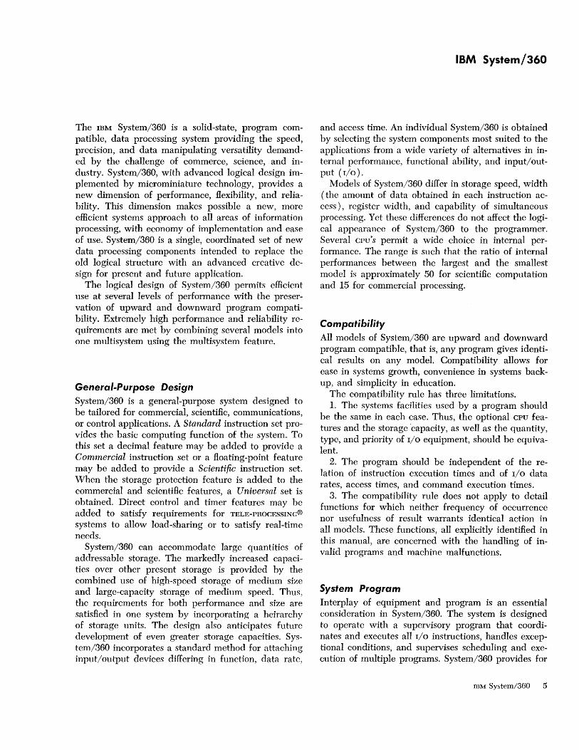
The IBM System/360 is a solid-state, program compatible, data processing system providing the speed, precision, and data manipulating versatility demanded by the challenge of commerce, science, and industry. System/360, with advanced logical design implemented by microminiature technology, provides a new dimension of performance, flexibility, and reliability. This dimension makes possible a new, more efficient systems approach to all areas of information processing, with economy of implementation and ease of use. System/360 is a single, coordinated set of new data processing components intended to replace the old logical structure with an advanced creative design for present and future application.
The logical design of System/360 permits efficient use at several levels of performance with the preservation of upward and downward program compatibility. Extremely high performance and reliability requirements are met by combining several models into one multisystem using the multisystem feature.
General-Purpose Design System/360 is a general-purpose system designed to be tailored for commercial, scientific, communications, or control applications. A Standard instruction set provides the basic computing function of the system .. To this set a decimal feature may be added to provide a Commercial instruction set or a floating-point feature may be added to provide a Scientific instruction set. When the storage protection feature is added to the commercial and scientific features, a Universal set is obtained. Direct control and timer features may be added to satisfy requirements for TELE-PROCESSINC@
systems to allow load-sharing or to satisfy real-time needs.
System/360 can accommodate large quantities of addressable storage. The markedly increased capacities over other present storage is provided by the combined use of high-speed storage of medium size and large-capacity storage of medium speed. Thus, the requirements for both performance and size are satisfied in one system by incorporating a heirarchy of storage units. The design also anticipates future development of even greater storage capacities. System/360 incorporates a standard method for attaching input/output devices differing in function, data rate,
IBM System/360
and access time. An individual System/360 is obtained by selecting the system components most suited to the applications from a wide variety of alternatives in internal performance, functional ability, and input/output (I/O).
Models of System/360 differ in storage speed, width (the amount of data obtained in each instruction access), register width, and capability of simultaneous processing. Yet these differences do not affect the logical appearance of System/360 to the programmer. Several cpu's permit a wide choice in internal performance. The range is such that the ratio of internal performances between the largest and the smallest model is approximately 50 for scientific computation and 15 for commercial processing.
Compatibility All models of System/360 are upward and downward program compatible, that is, any program gives identical results on any model. Compatibility allows for ease in systems growth, convenience in systems backup, and simplicity in education.
The compatibility rule has three limitations. 1. The systems facilities used by a program should
be the same in each case. Thus, the optional CPU features and the storage capacity, as well as the quantity, type, and priority of I/O equipment, should be equivalent.
2. The program should be independent of the relation of instruction execution times and of I/O data rates, access times, and command execution times.
3. The compatibility rule does not apply to detail functions for which neither frequency of occurrence nor usefulness of result warrants identical action in all models. These functions, all explicitly identified in this manual, are concerned with the handling of invalid programs and machine malfunctions.
System Program Interplay of equipment and program is an essential consideration in System/360. The system is designed to operate with a supervisory program that coordinates and executes all I/O instructions, handles exceptional conditions, and supervises scheduling and execution of multiple programs. System/360 provides for
IBM System/360 5
efficient switching from one program to another, as well as for the relocation of programs in storage. To the prob1em programmer, the supervisory program and the equipment are indistinguishable.
System Alerts The interruption system permits the CPU automatically to change state as a result of conditions arising outside of the system, in 1/0 units, or in the CPU itself. Interruption switches the CPU from one program to another by changing not only the instruction address but all essential machine-status information.
A storage protection feature permits one program to be preserved when another program erroneously attempts to store information in the area assigned to the first program. Protection does not cause any loss of performance. Storage operations initiated from the CPU, as well as those initiated from a channel, are subject to the protection procedure.
Programs are checked for correct instructions and data as they are executed. This policing-action identifies and separates program errors and machine errors. Thus, program errors cannot create machine checks since each type of error causes a unique interruption. In addition to an interruption due to machine malfunction, the information necessary to identify the error is recorded automatically in a predetermined storage location. This procedure appreciably reduces the mean-time to repair a machine fault. Moreover, operator errors are reduced by minimizing the active manual controls. To reduce accidental operator errors, operator consoles are 110 devices and function under control of the system program.
Multisystem Operation Several models of System/360 can be combined into one multisystem configuration. Three levels of communication between CPu's are available. Largest in capacity, and moderately fast in response, is communications by means of shared 1/0 device, for example,
6
a disk file. Faster transmission is obtained by direct connection between the channels of two individual systems. Finally, storage may be shared on some models between two cpu's, making information exchange possible at storage speeds. These modes of communication are supplemented by allowing one CPU to be interrupted by another CPU and by making direct status information available from one CPU to another.
Input/Output Channels provide the data path and control for 1/0
devices as they communicate with the CPU. In general, channels operate asynchronously with the CPU and, in some cases, a single data path is made up of several sub channels. When this is the case, the single data path is shared by several low-speed devices, for example, card readers, punches, printers, and terminals. This channel is called a multiplexor channel. Channels that are not made up of several such subchannels can operate at higher speed than the multiplexor channels and are called selector channels. In every case, the amount of data that comes into the channel in parallel from an 110 device is a byte. All channels or subchannels operate the same and respond to the same 110 instructions and commands.
Each 110 device is connected to one or more channels by an 110 interface. This 110 interface allows attachment of present and future 110 devices without altering the instruction set or channel function. Control units are used where necessary to match the internal connections of the 110 device to the interface. Flexibility is enhanced by optional access to a control unit or dcvice from either of two channels.
Technology System/360 employs solid-logic integrated components, which in themselves provide advanced equipment reliability. These components are also faster and smaller than previous components and lend themselves to automated fabrication.
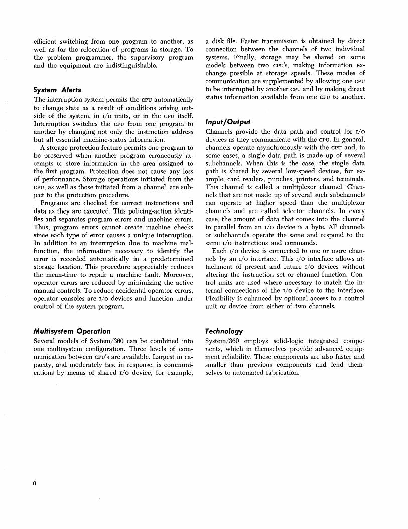
The basic structure of a System/360 consists of main storage, a central processing unit (cPu), the selector and multiplexor channels, and the input! output devices attached to the channels through control units. It is possible for systems to communicate with each other by means of shared I/O devices, a channel, or shared storage. Figure 1 shows the basic organization of a single system.
Main Storage Storage units may be either physically integrated with the CPU or constructed as stand-alone units. The storage cycle is not directly related to the internal cycling of the CPU, thus permitting selection of optimum storage speed for a given word size. The physical differences in the various main-storage units do not affect the logical structure of the system.
Fetching and storing of data by the CPU are not affected by any concurrent I/O data transfer. If an I/O
operation refers to the same storage location as the CPU operation, the accesses are granted in the sequence in which they are requested. If the first reference changes the contents of the location, any subsequent storage fetches obtain the new contents. Concurrent I/O and CPU references to the same storage location never cause a machine-check indication.
Main Storage
-Control '--
System Structure
Information Formats
The system transmits information between main storage and the CPU in units of eight bits, or a multiple of eight bits at a time. An eight-bit unit of information is called a byte, the basic building block of all formats. A ninth bit, the parity or check bit, is transmitted with each byte and carries parity on the bytes. The parity bit cannot be affected by the program; its only effect is to cause an interruption when a parity error is detected. References to the size of data fields and registers, therefore, exclude the associated parity bits. All storage capacities are expressed in number of bytes provided, regardless of the physical word size actually used.
Bytes may be handled separately or grouped together in fields. A halfword is a group of two consecutive bytes and is the basic building block of instructions. A word is a group of four consecutive bytes; a double word is a field consisting of two words (Figure 2). The location of any field or group of bytes is specified by the address of its leftmost byte.
The length of fields is either implied by the operation to be performed or stated explicitly as part of the instruction. When the length is implied, the information is said to have a fixed length, which can be either one, two, four, or eight bytes.
When the length of a field is not implied by the
Input/
I 1 - Output c Unit c f---t - Device ....c: U
f-----t c--
.... ~ f---i Q)
1 f-----t ""5 f---i ::E f----i
Central Processing t-
Input/ Unit Control t--
I-- Output f------\ Unit t- Device W c f---t
t--C c f---t ....c:
U --I ....
.8 --I u Q)
--I W Vl --I
Figure 1. IBM System/360 Basic Logical Structure
System Structure 7
operation code, but is stated explicitly, the information is said to have variable field length. Variablelength operands are variable in length by increments of one byte.
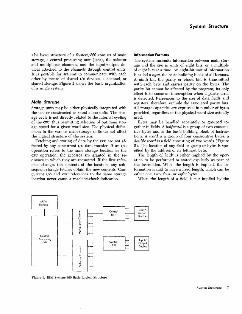
Within any program format or any fixed-length operand format, the bits making up the format are consecutively numbered from left to right starting with the number O.
Byte
Halfword
11 0 0 1 Jo 0 0 1 11 0 1 0 KO 0 1 01 15
Word
11 0 0 011 0 0 111 0 0 0 BO 0 1 011 0 0 1'1> 1 0 011 1 1 ~ 0 1 11 16 24 31
Figure 2. Sample Information Formats
Addressing
Byte locations in storage are consecutively numbered starting with 0; each number is considered the address of the corresponding byte. A group of bytes in storage is addressed by the leftmost byte of the group. The addressing capability permits a maximum of 16,777,216 bytes, using a 24-bit binary address. This set of main-storage addresses includes some locations reserved for special purposes.
Storage addressing wraps around from the maximum byte address, 16,777,215, to address O. Variable-length operands may be located partially in the last and partially in the first location of storage, and are processed without any special indication.
When only a part of the maximum storage capacity is available in a given installation, the available storage is normally contiguously addressable, starting at address O. An addressing exception is recognized when any part of an operand is located beyond the maximum available capacity of an installation.
In some models main storage may be shared by more than one CPU. In that case, the address of a byte location is normally the same for each CPU.
Informatic)n Positioning
Fixed-length fields, such as halfwords and double words, must be located in main storage on an integral boundary for that unit of information. A boundary is called integral for a unit of information when its stor-
8
age address is a multiple of the length of the unit in bytes. For example, words (four bytes) must be located in storage so that their address is a multiple of the number 4. A halfword (two bytes) must have an address that is a multiple of the number 2, and double words (eight bytes) must have an address that is a multiple of the number 8.
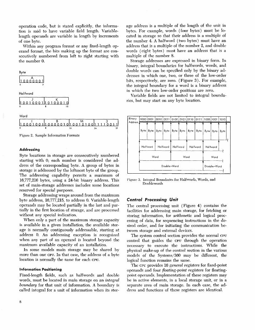
Storage addresses are expressed in binary form. In binary, integral boundaries for halfwords, words, and double words can be specified only by the binary addresses in which one, two, or three of the low-order bits, respectively, are zero. (Figure 3). For example, the integral boundary for a word is a binary address in which the two low-order positions are zero.
Varia ble fields are not limited to integral boundaries' but may start on any byte location.
Binary 0000 0001 0010 0011 0100 01Ql 0110 0111 1000 1001 1010 Address
Byte Byte Byte Byte Byte Byte Byte Byte Byte Byte Byte
Halfword Halfword Halfword Halfword Halfword , l
Word Word Word -(
Double-Word Double-Word
Figure 3. Integral Boundaries for Halfwords, Words, and Doublewords
Central Processing Unit
)
l
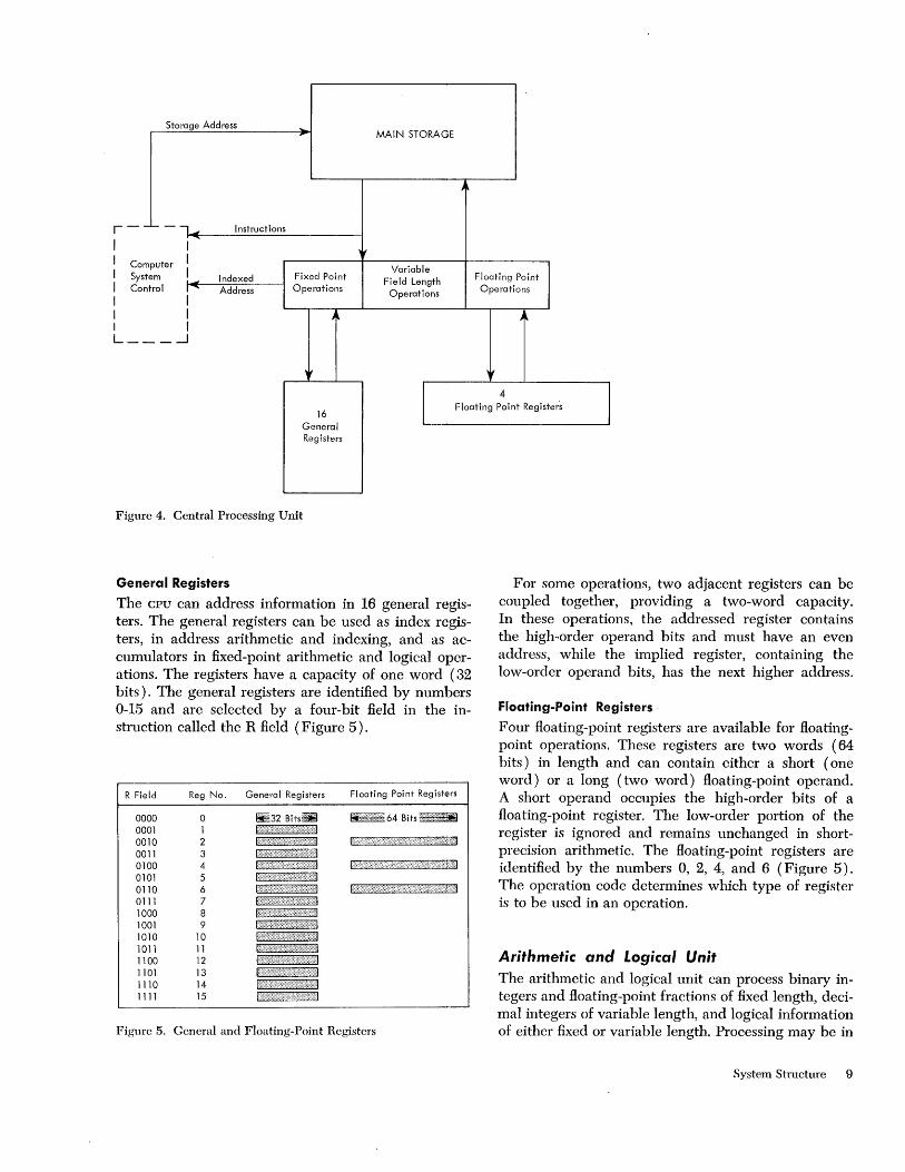
The central processing unit (Figure 4) contains the facilities for addressing main storage, for fetching or storing information, for arithmetic and logical processing of data, for sequencing instructions in the desired order, and for initiating the communication between storage and external devices.
The system control section provides the normal CPU
control that guides the CPU through the operation necessary to execute the instructions. While the physical make-up of the control section in the various models of the Systems/360 may be different, the logical function remains the same.
The CPU provides 16 general registers for fixed-point operands and four floating-point registers for floatingpoint operands. Implementation of these registers may be in active elements, in a local storage unit, or in a separate area of main storage. In each case, the address and functions of these registers are identical.
, l
Storage Address
r- -'- -lOll( I I
Instructions
I Co mputer I I Sys tem I I
~
Co ntrol , ..... Indexed Address
I I I I I I L_ __ .-J
Fixed Point Operations
MAIN STORAGE
Variable Field Length
Operations
J
Floating Point Operations
4
16 General Registers
I Floating Point Registers
Figure 4. Central Processing Unit
General Registers
The CPU can address information in 16 general registers. The general registers can be used as index registers, in address arithmetic and indexing, and as accumulators in fixed-point arithmetic and logical operations. The registers have a capacity of one word (32 bits). The general registers are identified by numbers 0-15 and are selected by a four-bit field in the instruction called the R field (Figure 5).
R Field Reg No. General Registers Floating Point Registers
0000 0 !i±32 Bits. hi:"":.'::::"': 64 Bits :::':":::::::::::::::;1I!l:1 0001 1 0010 2 0011 3 0100 4 0101 5 0110 6 ....... ,,' .. ··· .. ·'·:1
0111 7 1000 8 1001 9 1010 10 1011 11 1100 12 1101 13 1110 14 1111 15
Figure 5. General and Floating-Point Registers
For some operations, two adjacent registers can be coupled together, providing a two-word capacity. In these operations, the addressed register contains the high-order operand bits and must have an even address, while the implied register, containing the low-order operand bits, has the next higher address.
Floating-Point Registers
Four floating-point registers are available for floatingpoint operations. These registers are two words (64 bits) in length and can contain either a short (one word) or a long (two word) floating-point operand. A short operand occupies the high-order bits of a floating-point register. The low-order portion of the register is ignored and remains unchanged in shortprecision arithmetic. The floating-point registers are identified by the numbers 0, 2, 4, and 6 (Figure 5). The operation code determines which type of register is to be used in an operation.
Arithmetic and Logical Unit The arithmetic and logical unit can process binary integers and floating-point fractions of fixed length, decimal integers of variable length, and logical information of either fixed or variable length. Processing may be in
System Structure 9
parallel or in series; the width of the arithmetic unit, the multiplicity of the shifting paths, and the degree of simultaneity in performing the different types of arithmetic differ from one CPU to another without affecting the logical appearance of the design.
Arithmetic and logical operations performed by the CPU fall into four classes: fixed-point arithmetic, decimal arithmetic, floating-point arithmetic, and logical operations. These classes differ in the data formats used, the registers involved, the operations provided, and the way the field length is stated.
Fixed-Point Arithmetic
The basic arithmetic operand is the 32-bit fixed-point binary word. Sixteen-bit halfword operands may be specified in most operations for improved performancc or storage utilization. See Figure 6. To preserve precision, some products and all dividends are 64 bits long.
Integer o 1 15
Integer
o 1 31
Figure 6. Fixed-Point Number Formats
Because the 32-bit word size conveniently accommodates a 24-bit address, fixed-point arithmetic can be used both for integer operand arithmetic and for address arithmetic. This combined usage provides economy and permits the entire fixed-point instruction set and several logical operations to be used in address computation. Thus, multiplication, shifting, and logical manipulation of address components are possible.
The absence of recomplementation and the ease of extension and truncation make two's-complement notation desirable for address components and fixedpoint operands. Since integer and addressing algorisms often require repeated reference to operands or intermediate results, the use of multiple registers is advantageous in arithmetic sequences and address calculations.
Additions, subtractions, multiplications, divisions, and comparisons are performed upon one operand in a register and another operand either in a register or from storage. Multiple-precision operation is made convenient by the two's-complement notation and by recognition of the carry from one word to another. A
10
word in one register or a double word in a pair of adjacent registers may be shifted left or right. A pair of conversion instructions - CONVERT TO BINARY and CONVERT TO DECIMAL - provides transition between decimal and binary radix (number base) without the use of tables. Multiple-register loading and storing instructions facilitate subroutine switching.
Decimal Arithmetic
Decimal arithmetic is designed for processes requiring few computational steps between the source input and the documented output. This type of processing is frequently found in commercial applications, particularly when use is made of problem-oriented languages. Because of the limited number of arithmetic operations performed on each item of data, radix conversion from decimal to binary and back to decimal is not justified, and the use of registers for intermediate results yields no advantage over storage-to-storage processing. Hence, decimal arithmetic is provided, and both operands and results are located in storage. Decimal arithmetic includes addition, subtraction, multiplication, division, and comparison.
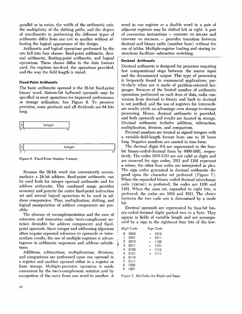
Decimal numbers are treated as signed integers with a variable-field-length format from one to 16" bytes long. Negative numbers are carried in true form.
The decimal digits 0-9 are represented in the fourbit binary-cod ed-decimal form by 0000-1001, respectively. The codes 1010-1111 are not valid as digits and are reserved for sign codes; 1011 and 1101 represent a minus; the other four codes are interpreted as plus. The sign codes generated in decimal arithmetic depend upon the character set preferred (Figure 7). When the expanded binary coded decimal interchange code (EBCDIC) is preferred, the codes are 1100 and 1101. When the ASCII set, expanded to eight bits, is preferred, the codes are 1010 and 1011. The choice between the two code sets is determined by a mode bit.
Decimal operands are represented by four-bit binary-coded-decimal digits packed two to a byte. They appear in fields of variable length and are accompanied by a sign in the rightmost four bits of the low-
Digit Code Sign Code
0 0000 + 1010 1 0001 - 1011 2 0010 + 1100 3 0011 - 1101 4 0100 + 1110 5 0101 + 1111 6 0110 7 0111 8 1000 9 1001
Pigure 7. Bit Codes for Digits and Signs
order byte. Operand fields may be located on any byte boundary, and may have length up to 31 digits and sign. Operands participating in an operation have independent lengths. Packing of digits within a byte (Figure 8) and of variable-length fields within storage results in efficient use of storage, in increased arithmetic performance, and in an improved rate of data transmission between storage and files.
I Digit I Digit I Digit [~~ ~-J Digit I Digit I Digit I Digit I Sign I
I Zone I Digit I Zone C-_- ~~] Digit I Zone I Digit I Sign I Digit I
Figure 8. Packed and Zoned Decimal Number Formats
Decimal numbers may also appear in a zoned format as a subset of the eight-bit alphameric character set (Figure 8). This representation is required for character-set sensitive I/O devices. The zoned format is not used in decimal arithmetic operations. Instructions are provided for packing and unpacking decimal numbers so that they may be changed from the zoned to the packed format and vice versa.
Floating-Point Arithmetic
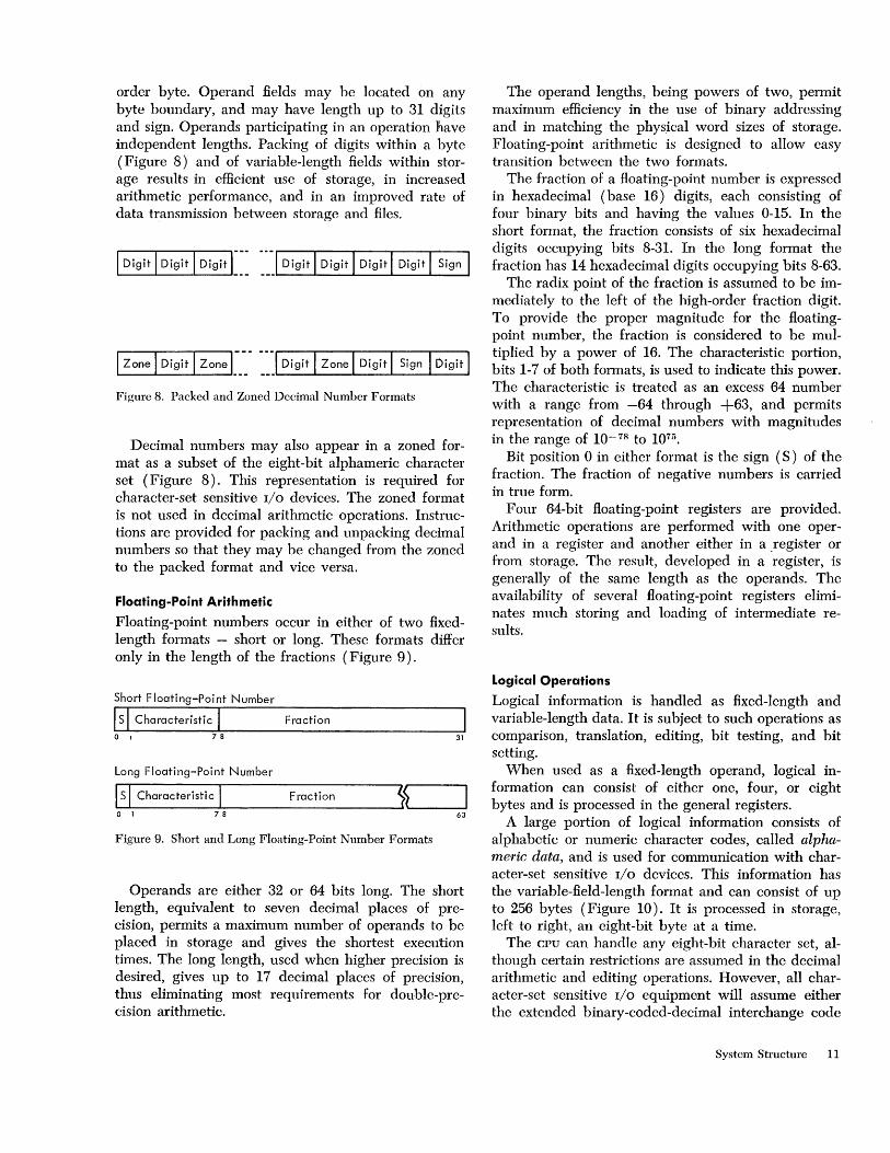
Floating-point numbers occur in either of two fixedlength formats - short or long. These formats differ only in the length of the fractions (Figure 9).
Short Floating-Point Number
IS I Characteristic I Fraction o I 7 8 31
Long Floating-Point Number
~IS~I_C_h_a_r_ac_t_e_ri_st_ic~I _________ F_ra_c_ti_o_n ______ ~~~~ ______ ~ o 1 78 63
Figure 9. Short and Long Floating-Point Number Formats
Operands are either 32 or 64 bits long. The short length, equivalent to seven decimal places of precision, permits a maximum number of operands to be placed in storage and gives the shortest execution times. The long length, used when higher precision is desired, gives up to 17 decimal places of precision, thus eliminating most requirements for double-precision arithmetic.
The operand lengths, being powers of two, permit maximum efficiency in the use of binary addressing and in matching the phys,ical word sizes of storage. Floating-point arithmetic is designed to allow easy transition between the two formats.
The fraction of a floating-point number is expressed in hexadecimal ( base 16) digits, each consisting of four binary bits and having the values 0-15. In the short format, the fraction consists of six hexadecimal digits occupying bits 8-31. In the long format the fraction has 14 hexadecimal digits occupying bits 8-63.
The radix point of the fraction is assumed to be immediately to the left of the high-order fraction digit. To provide the proper magnitude for the floatingpoint number, the fraction is considered to be multiplied by a power of 16. The characteristic portion, bits 1-7 of both formats, is used to indicate this power. The characteristic is treated as an excess 64 number with a range from -64 through +63, and permits representation of decimal numbers with magnitudes in the range of 10-78 to 1075 •
Bit position 0 in either format is the sign (S) of the fraction. The fraction of negative numbers is carried in true form.
Four 64-bit floating-point registers are provided. Arithmetic operations are performed with one operand in a register and another either in a .register or from storage. The result, developed in a register, is generally of the same length as the operands. The availability of several floating-point registers eliminates much storing and loading of intermediate results.
Logical Operations
Logical information is handled as fixed-length and variable-length data. It is subject to such operations as comparison, translation, editing, bit testing, and bit setting.
When used as a fixed-length operand, logical information can consist of either one, four, or eight bytes and is processed in the general registers.
A large portion of logical information consists of alphabetic or numeric character codes, called alphameric data, and is used for communication with character-set sensitive I/O devices. This information has the variable-field-Iength format and can consist of up to 256 bytes (Figure 10). It is processed in storage, left to right, an eight-bit byte at a time.
The CPU can handle any eight-bit character set, although certain restrictions are assumed in the decimal arithmetic and editing operations. However, all character-set sensitive I/O equipment will assume either the extended binary-coded-decimal interchange code
System Structure 11
Fixed Lengl'h Logical Information
I Logical Data
Variable-Length Logical Information
I Character I Character I-~~ 16
~~] Character
Figure 10. Fixed-Length and Variable-Length Logical Information
31
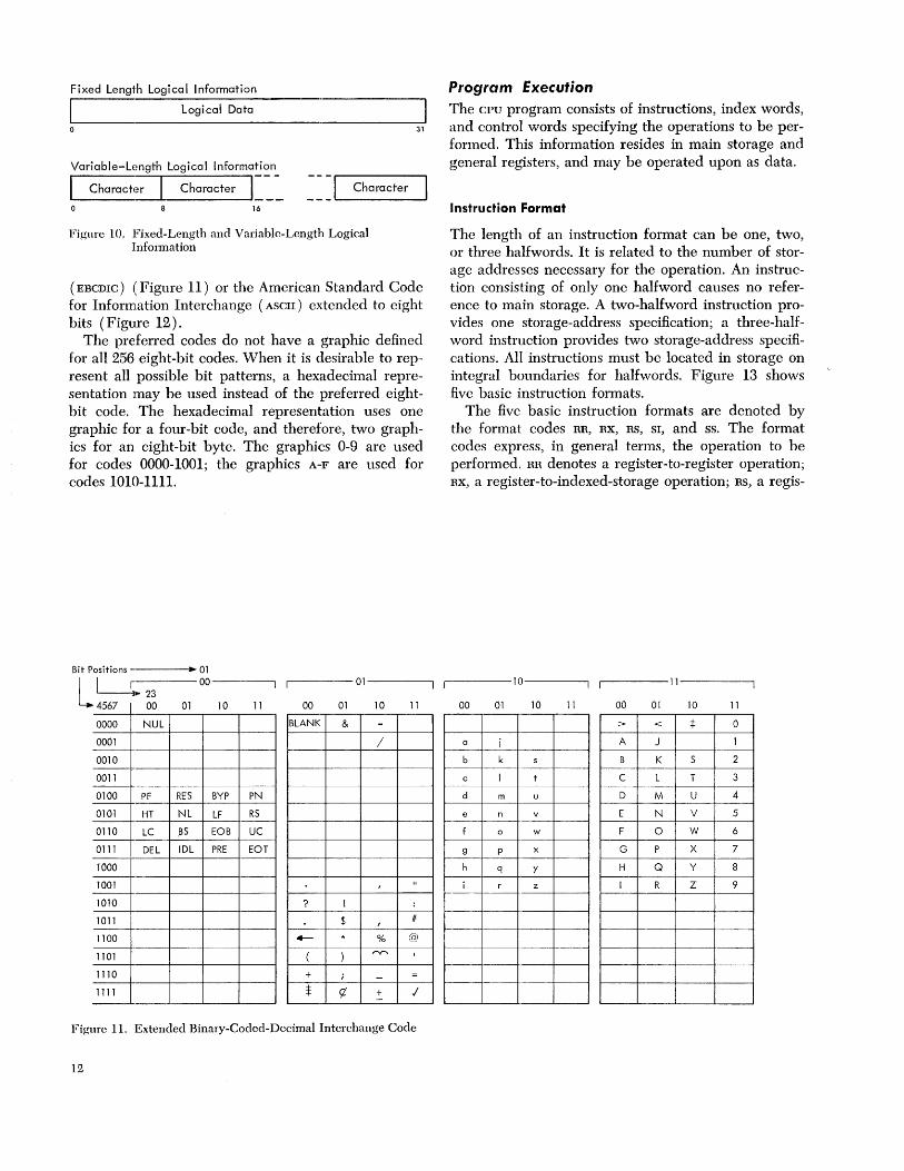
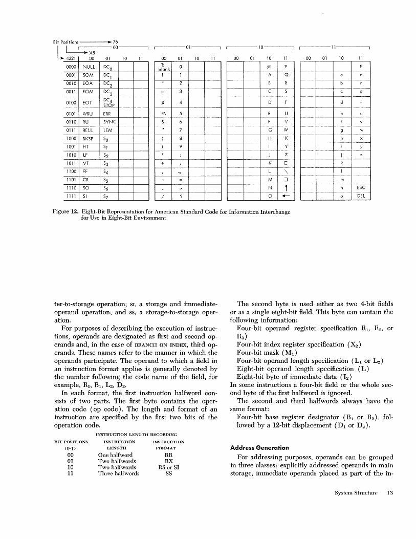
( EBCDIC) (Figure 11) or the American Standard Code for Information Interchange (ASCII) extcnded to eight bits (Figure 12).
The preferred codes do not have a graphic defined for all 256 eight-bit codes. When it is desirable to represent all possible bit patterns, a hexadecimal representation may be used instead of the preferred eightbit code. The hexadecimal representation uses one graphic for a four-bit code, and therefore, two graphics for an eight-bit byte. The graphics 0-9 are used for codes 0000-1001; the graphics A-F are used for codes 1010-1111.
Bit Positions -,----. .. 01 L U:-2-3--00------,
4567 00 01 10 11
~------01------~
00 01 10 11
0000 NUL BLANK & -0001 / 0010
0011
0100 PF RES BYP PN
0101 HT NL LF RS
0110 LC .BS EOB UC -0111 DEL IDL PRE EOT
1000 --
1001 , " 1010 ? ! :
1011 $ , #
1100 4--- * % @
1101 ( ) ry-.. I
1110 + ; - =
1111 $ C7 + j -
Figure 11. Extended Binary-Coded-Decimal Interchange Code
12
Program Execution The CPU program consists of instructions, index words, and control words specifying the operations to be performed. This information resides in main storage and general registers, and may be operated upon as data.
Instruction Format
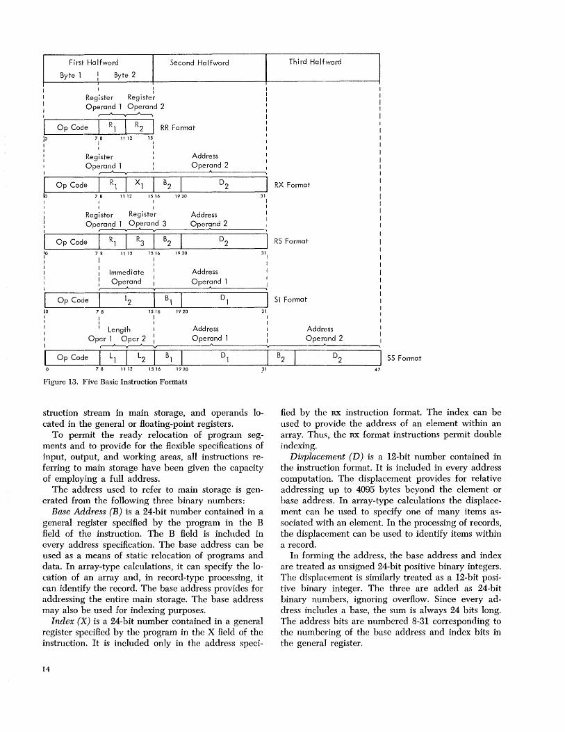
The length of an instruction format can be one, two, or three halfwords. It is related to the number of storage addresses necessary for the operation. An instruction consisting of only one halfword causes no reference to main storage. A two-halfword instruction provides one storage-address specification; a three-halfword instruction provides two storage-address specifications. All instructions must be located in storage on integral boundaries for halfwords. Figure 13 shows five basic instruction formats.
The five basic instruction formats are denoted by the format codes RR, RX, RS, SI, and ss. The format codes express, in general terms, the operation to be performed. RR denotes a register-to-register operation; RX, a register-to-indexed-storage operation; RS, a regis-
~------10---~ ~-----11----------,
00 01 10 11 00 01 10 11
> < :j: 0
a i A J 1
b k s B K S 2
c I t C L T 3
d m u D M U 4
e n v E N V 5
f 0 w F 0 W 6
9 P x G P X 7
h q y H Q Y 8
i r z I R Z 9 1----- _._---
Bit Positions ----•• 76 L I • X5 00------,
4321 00 01 10 11
01
00 01 10 11 00 01 10
..----10-------.1 '--1 ----11-------.
11 00 01 10 11 ~-~-~-~----~
0000 NULL DCa b a blank (a) P
0001 50M DC1
--- ,---- ----- - r----A- --- ---Q a q
0010 EOA DC2
0011 EOM DC3
2
41= 3 --
B R
C 5
b r I---+----t-------f --------
C S
-- 1------+----+ ----~
0100 EOT DC4 5TOP $ 4 D T d t
0101 WRU ERR % 5 E U e u --- ---- ----- 1---- -- -- - f-------f----J-----j
0110 RU 5YNC & 6 F V v
0111 BELL LEM --,------ ----"- ~ ~---,
7 - f---
G W - --- - -- - -------
9 W
1000 BK5P 50
1001 HT 51
8
9
H X --f-- -
I Y f-----
~--+--_+--T_-~
h x ---- 1----:- -- ----
I Y - I-- -- -~ -----f-----, ~
1010 LF 52 J Z i z r------ ------+----__j ---
1011 VT 53 + K [ k r------r--+---~--__j
1100 FF 54 ~
-~-- ----L " --~ r--·--r---+--1--
1101 CR 55 M ::J m
1110 50 56 N f r----- r- - -f- -- - ---
n E5C 1--- r- -- ----1----I ----------
1111 51 57 / ? 0 4-- o DEL
Figure 12. Eight-Bit Representation for American Standard Code for Information Interchange for Use in Eight-Bit Environment
ter-to-storage operation; SI, a storage and immediateoperand operation; and SS, a storage-to-storage operation.
For purposes of describing the execution of instructions, operands are designated as first and second operands and, in the case of BRANCH ON INDEX, third operands. These names refer to the manner in which the operands participate. The operand to which a field in an instruction format applies is generally denoted by the number following the code name of the field, for example, Rl, Bl, L2, D 2 •
In each format, the first instruction halfword consists of two parts. The first byte contains the operation code (op code). The length and format of an instruction are specified by the first two bits of the operation code.
INSTRUCTION LENGTH RECORDING
BIT POSITIONS INSTRUCTION INSTRUCTION
<0-1) LENGTH FORMAT
00 One halfword RR 01 Two halfwords RX 10 Two halfwords RS or SI 11 Three halfwords SS
The second byte is used either as two 4-bit fields or as a single eight-bit field. This byte can contain the following information:
Four-bit operand register specification Rb R2, or R3 )
Four-bit index register specification (X2 )
Four-bit mask (M1 )
Four-bit operand length specification (Ll or L2 )
Eight-bit operand length specification (L) Eight-bit byte of immediate data (12 )
In some instructions a four-bit field or the whole second byte of the first halfword is ignored.
The second and third halfwords always have the same format:
Four-bit base register designator (Bl or B2 ), followed by a 12-bit displacement (Dl or D2)'
Address Generation
For addressing purposes, operands can be grouped in three classes: explicitly addressed operands in main storage, immediate operands placed as part of the in-
System Structure 13
L-____ F_ir_s.t __ H_aT�f_w_o_rd ______ -; ____ s_ec_o_n_d __ H_a_�f_W_O_rd ________ ~----Th-i_rd--H_a_lf~ r Byte' Byte 2 ~
I :0 1 I I I
10
I I
Register Register Operand' Operand 2 ~
Op Code I R 1 I R2 I RR Format 7 8 11 12 15
1
Register Operand' ~
Op Code I R, I X, B2
7 8 11 12 1516 I
I I
Register Register Operand' Operand 3
r---' ..---A-----y
7 8
I 11 12
Immediate Ope~and
Op Code 12
1516 I
78 1516 I 1 I I
1920
1920
1920
Address Operand 2
"
D2 31
Address Oper~ ___ _
Address
Oper?nd 1
31
31
1 I I
RX Format
RS Format
SI Format
I Length I Address Address
Op~ ____ ----O-p_e-ra~An-d--'------~~----__ O--p-e~r?-n-d-2------~ SS Format Op Code I L, I L2 I B, D,
7 8 11 12 15 16 1920 ------.-31-'--------1----------------'47
Figure 13. Five Basic Instruction Formats
struction stream in main storage, and operands located in the general or floating-point registers.
To permit the ready relocation of program segments and to provide for the flexible specifications of input, output, and working areas, all instructions referring to main storage have been given the capacity of employing a full address.
The address used to refer to main storage is generated from the following three binary numbers:
Base Address (B) is a 24-bit number contained in a general register specified by the program in the B field of the instruction. The B field is included in every address specification. The base address can be used as a means of static relocation of programs and data. In array-type calculations, it can specify the location of an array and, in record-type processing, it can identify the record. The base address provides for addressing the entire main storage. The base address may also be used for indexing purposes.
Index (X) is a 24-bit number contained in a general register specified by the program in the X field of the instruction. It is included only in the address speci-
14
fied by the RX instruction format. The index can be used to provide the address of an element within an array. Thus, the RX format instructions permit double indexing.
Displacement (D) is a 12-bit number contained in the instruction format. It is included in every address computation. The displacement provides for relative addressing up to 4095 bytes beyond the element or base address. In array-type calculations the displacement can be used to specify one of many items associated with an element. In the processing of records, the displacement can be used to identify items within a record.
In forming the address, the base address and index are treated as unsigned 24-bit positive binary integers. The displacement is similarly treated as a 12-bit positive binary integer. The three are added as 24-bit binary numbers, ignoring overflow. Since every address includes a base, the sum is always 24 bits long. The address bits are numbered 8-31 corresponding to the numbering of the base address and index bits in the general register.
The program may have zeros in the base address, index, or displacement fields. A zero is used to indicate the absence of the corresponding address component. A base or index of zero implies that a zero quantity is to be used in forming the address, regardless of the contents of general register O. A displacement of zero has no special significance. Initialization, modification, and testing of base addresses and indexes can be carried out by fixed-point instructions, or by BRANCH AND LINK, BRANCH ON COUNT, or BRANCH
ON INDEX instructions. As an aid in describing the logic of the instruction
format, examples of two instructions and their related instruction formats follow.
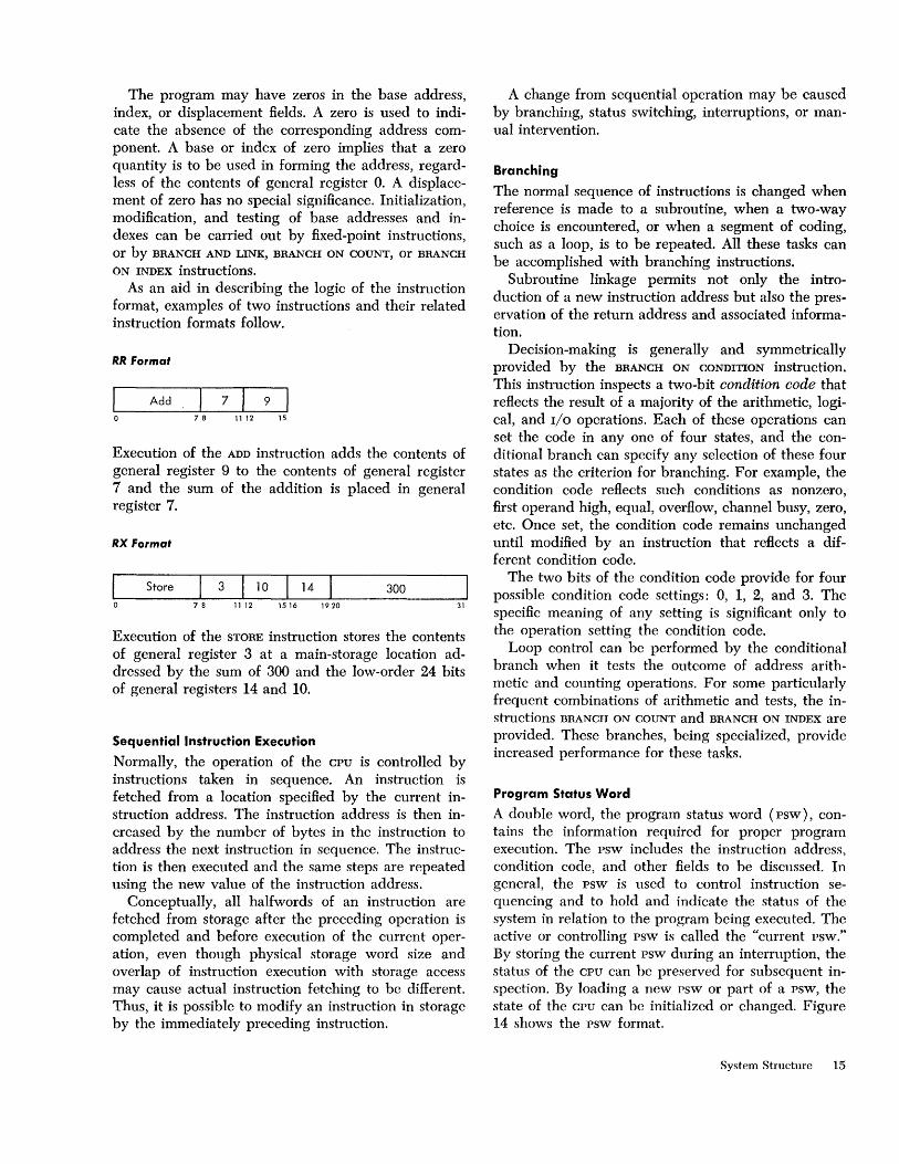
RR Format
I Add 7 9 o 78 1112 15
Execution of the ADD instruction adds the contents of general register 9 to the contents of general register 7 and the sum of the addition is placed in general register 7.
RX Format
Store 3 10 14 300 7 8 11 1 2 15 16 1 9 20 31
Execution of the STORE instruction stores the contents of general register 3 at a main-storage location addressed by the sum of 300 and the low-order 24 bits of general registers 14 and 10.
Sequential Instruction Execution
Normally, the operation of the CPU is controlled by instructions taken in sequence. An instruction is fetched from a location specified by the current instruction address. The instruction address is then increased by the number of bytes in the instruction to address the next instruction in sequence. The instruction is then executed and the same steps are repeated using the new value of the instruction address.
Conceptually, all halfwords of an instruction are fetched from storage after the preceding operation is completed and before execution of the current operation, even though physical storage word size and overlap of instruction execution with storage access may cause actual instruction fetching to be different. Thus, it is possible to modify an instruction in storage by the immediately preceding instruction.
A change from sequential operation may be caused by branching, status switching, interruptions, or manual intervention.
Branching
The normal sequence of instructions is changed when reference is made to a subroutine, when a two-way choice is encountered, or when a segment of coding, such as a loop, is to be repeated. All these tasks can be accomplished with branching instructions.
Subroutine linkage permits not only the introduction of a new instruction address but also the preservation of the return address and associated information.
Decision-making is generally and symmetrically provided by the BRANCH ON CONDITION instruction. This instruction inspects a two-bit condition code that reflects the result of a majority of the arithmetic, logical, and I/O operations. Each of these operations can set the code in anyone of four states, and the conditional branch can specify any selection of these four states as the criterion for branching. For example, the condition code reflects such conditions as nonzero, first operand high, equal, overflow, channel busy, zero, etc. Once set, the condition code remains unchanged until modified by an instruction that reflects a different condition code.
The two bits of the condition code provide for four possible condition code settings: 0, 1, 2, and 3. The specific meaning of any setting is significant only to the operation setting the condition code.
Loop control can be performed by the conditional branch when it tests the outcome of address arithmetic and counting operations. For some particularly frequent combinations of arithmetic and tests, the instructions BRANCH ON COUNT and BRANCH ON INDEX are provided. These branches, being specialized, provide increased performance for these tasks.
Program Status Word
A double word, the program status word (psw), contains the information required for proper program execution. The psw includes the instruction address, condition code, and other fields to be discussed. In general, the psw is used to control instruction sequencing and to hold and indicate the status of the system in relation to the program being executed. The active or controlling psw is called the "current psw." By storing the current psw during an interruption, the status of the CPU can be preserved for subsequent inspection. By loading a new psw or part of a psw, the state of the CPU can be initialized or changed. Figure 14 shows the psw format.
System Structure 15

0-7 System mask o Multiplexor channel mask 1 Selector c:hannel 1 mask 2 Selector c:hannel 2 mask 3 Selector channel 3 mask 4 Selector c:hannel 4 mask 5 Selector c:hannel 5 mask 6 Selector c:hannel 6 mask 7 External mask
8-11 Protection key 12 ASCII mode (A) 13 Machine check mask (M)
14 Wait state (W) 15 Problem state (P)
16-31 Interruption code 32-33 Instruction Length code (ILC) 34-35 Condition code (CC) 36-39 Program mask
36 Fixed-point overflow mask 37 Decimal overflow mask 38 Exponent underflow mask 39 Significance mask
40-63 Instruction address
Figure 14. Program Status Word Format
Interrupti~.n
The interruption system permits the CPU to change state as a result of conditions external to the system, in input/output (I/O) units or in the CPU itself. Five classes of interruption conditions are possible: I/O,
program, supervisor call, external, and machine check. Each class has two related psw's called "old" and
"new" in unique main-storage locations (Figure 15). In all classes, an interruption involves merely storing the current psw in its "old" position and making the psw at the "new" position the current psw. The "old" psw holds all necessary status information of the system existing at the time of the interruption. If, at the conclusion of the interruption routine, there is an instruction to make the old psw the current psw, the system is lrestored to the state prior to the interruption and the interrupted routine continues.
Address length Purpose
o 0000 0000 double word Initial program loading PSW 8 0000 1000 double word Initial program loading CCWI
16 0001 0000 double word Initial program loading CCW2 24 0001 1000 double word External old PSW 32 0010 0000 double word Supervisor call old PSW 40 0010 1000 double word Program old PSW 48 0011 0000 double word Machine check old PSW 56 0011 1000 double word Input/output old PSW 64 0100 0000 double word Channel status word 72 0100 1000 word Channel address word 76 0100 1100 word Unused 80 0101 0000 word Timer 84 0101 0100 word Unused 88 0101 1000 double word External new PSW 96 0110 0000 double word Supervisor call new PSW
1 04 011 a 1000 double word Program new PSW 112 0111 0000 double word Machine check new PSW 120 0111 1000 double word Input/output new PSW 128 1000 0000 Diagnostic scan-out area *
* The size of j,he diagnostic scan-out area depends upon the particular system's CPU and I/O channels.
Figure 15. Permanent Storage Assignments
16
Interruptions are taken only when the CPU is interruptable for the interruption source. The system mask, program mask, and machine check mask bits in the psw may be used to mask certain interruptions. When masked off, an interruption either remains pending or is ignored. The system mask may keep I/O and external interruptions pending, the program mask may cause four of the 15 program interruptions to be ignored, and the machine-check mask may cause machine-check interruptions to be ignored. Other interruptions cannot be masked off.
An interruption always takes place after one instruction execution is finished and before a new instruction execution is started. However, the occurence of an interruption may affect the execution of the current instruction. To permit proper programmed action following an interruption, the cause of the interruption is identified and provision is made to locate the last executed instruction.
Input /OutPIJt Interruption
An I/O interruption provides a means by which the CPU responds to conditions in the channels and I/O
units. An I/O interruption can occur only when the related
channel is not masked. The address of the channel and I/O unit involved are recorded in the old psw. Further information concerning the I/O action is preserved in the channel status word (csw) that is stored during the interruption.
Program Interruption
Unusual conditions encountered in a program create program interruptions. These conditions include incorrect operands and operand specifications, as well as exceptional results. The interruption code identifies the interruption cause. Figure 16 shows the different causes that may occur.
Interruption Program Interrupti on Code Cause
1 00000001 Operation 2 00000010 Privileged operation 3 00000011 Execute 4 00000100 Protection 5 00000101 Addressing 6 00000110 Specification 7 00000111 Date 8 00001000 Fixed-point overflow 9 00001001 Fixed-point divide
10 00001010 Decimal overflow 11 0000101 I Decimal divide 12 00001100 Exponent overflow 13 000011 01 Exponent underflow 14 00001 110 Significance 15 00001111 Floating-point divide
Figure 16. Interruption Code for Program Interruption
Supervisor-Call Interruption
This interruption occurs as a result of execution of the instruction SUPERVISOR CALL. Eight bits from the instruction format are placed in the interruption code of the old psw, permitting a message to be associated with the interruptions. A major use for the instruction SUPERVISOR CALL is to switch from the problem-state to the supervisor state. This interruption may also be used for other modes of status-switching.
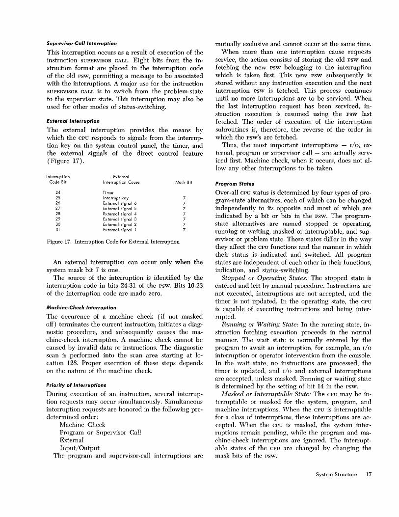
External Interruption
The external interruption provides the means by which the CPU responds to signals from the interruption key on the system control panel, the timer, and the external signals of the direct control feature (Figure 17).
Interruption External Code Bit I nterrupti on Cause Mask Bit
24 Timer 25 Interrupt key 7 26 External signal 6 7 27 External signal 5 7 28 External signal 4 7 29 External signal 3 7 30 External signal 2 7 3'1 External signal 1 7
Figure 17. Interruption Code for External Interruption
An external interruption can occur only when the system mask bit 7 is one.
The source of the interruption is identified by the interruption code in bits 24-31 of the psw. Bits 16-23 of the interruption code are made zero.
Machine-Check Interruption
The occurence of a machine check (if not masked off) terminates the current instruction, initiates a diagnostic procedure, and subsequently causes the machine-check interruption. A machine check cannot be caused by invalid data or instructions. The diagnostic scan is performed into the scan area starting at location 128. Proper execution of these steps depends on the nature of the machine check.
Priority of Interruptions
During execution of an instruction, several interruption requests may occur simultaneously. Simultaneous interruption requests are honored in the following predetermined order:
Machine Check Program or Supervisor Call External Input/Output
The program and supervisor-call interruptions are
mutually exclusive and cannot occur at the same time. When more than one interruption cause requests
service, the action consists of storing the old psw and fetching the new psw belonging to the interruption which is taken first. This new psw subsequently is stored without any instruction execution and the next interruption psw is fetched. This process continues until no more interruptions are to be serviced. When the last interruption request has been serviced, instruction execution is resumed using the psw last fetched. The order of execution of the interruption subroutines is, therefore, the reverse of the order in which the psw's are fetched.
Thus, the most important interruptions - I/O, external, program or supervisor call - are actually serviced first. Machine check, when it occurs, does not allow any other interruptions to be taken.
Program States
Over-all CPU status is determined by four types of program-state alternatives, each of which can be changed independently to its opposite and most of which are indicated by a bit or bits in the psw. The programstate alternatives are named stopped or operating, running or waiting, masked or interruptable, and supervisor or problem state. These states differ in the way they affect the CPU functions and the manner in which their status is indicated and switched. All program states are independent of each other in their functions, indication, and status-switching.
Stopped or Operating States: The stopped state is entered and left by manual procedure. Instructions are not executed, interruptions are not accepted, and the timer is not updated. In the operating state, the CPU
is capable of executing instructions and being interrupted.
Running or Waiting State: In the running state, instruction fetching execution proceeds in the normal manner. The wait state is normally entered by the program to await an interruption, for example, an I/O
interruption or operator intervention from the console. In the wait state, no instructions are processed, the timer is updated, and 110 and external interruptions are accepted, unless masked. Running or waiting state is determined by the setting of bit 14 in the psw.
Masked or Interruptable State: The CPU may be interruptable or masked for the system, program, and machine interruptions. \Vhen the CPU is interruptable for a class of interruptions, these interruptions are accepted. When the CPU is masked, the system interruptions remain pending, while the program and machine-check interruptions are ignored. The interruptable states of the CPU are changed by changing the mask bits of the psw.
System Structure 17

Supervisor or Problem State: In the problem state, all 110 instructions and a group of control instructions are invalid. In the supervisor state, all instructions are valid. The choice of problem or supervisor state is determined by bit 15 of the psw.
Protection feature The Protection Feature protects the contents of certain areas of storage from destruction due to erroneous storing of information during the execution of a program. This protection is achieved by identifying blocks of storage with a storage key and comparing this key with a protection key supplied with the data to be stored. The detection of a mismatch results in a protection interruption.
For protection purposes, main storage is divided into blocks of 2,048 bytes. A four-bit storage key is associated with each block. When data are stored in a storage block, the storage key is compared with the protection key. When storing is specified by an instruction, the protection key of the current psw is used as the comparand. When storing is specified by a channel operation, a protection key supplied by the channel iis used as the comparand. The keys are said to match when they are equal or when either one is zero.
The storage key is not part of addressable storage. The key is changed by SET STORAGE KEY and is inspected by INSERT STORAGE KEY. The protection key in the psw occupies bits 8-11 of that control word. The protection key of a channel is recorded in bits 0-3 of the csw, which is stored as a result of the channel operation. When a protection mismatch due to an instruction is detected, the execution of this instruction is suppressed or terminated, and the program execution is altered by an interruption. The protected storage location always remains unchanged. Protection mismatch due to an 110 operation causes the data transmission to be terminated in such a way that the protected storage location remains unchanged. The mismatch is indicated in the csw stored as a result of the operation.
Timer f'eature The timer is provided as an interval timer and may be programmed to maintain the time of day. The timer consists of a full word in main storage location 80. The timer word is counted down at a rate of 50 or 60 cycles per second, depending on line frequency. The timer word is treated as a signed integer following the rules of fixed-point arithmetic. An external interruption condition is signaled when the value of the
18
timer word goes from positive to negative. The full cycle time of the timer is 15.5 hours.
An updated timer value is available at the end of each instruction execution but is not updated in the stopped state. The timer is changed by addressing storage location 80. As an interval timer, the timer is used to measure elapsed time over relatively short intervals. It can be set to any value at any time.
Direct Control feature The direct control feature provides two instructions, READ DIRECT and WRITE DIRECT, and six external interruption lines. The read and write instructions provide for the transfer of a single byte of information between an external device and the main storage of the system. It is usually most desirable to use the data channels of the system to handle the transfer of any volume of information and u.se the direct data control feature to pass controlling and synchronizing information between the CPU and special external devices.
Each of the six external signal lines, when pulsed, sets up the conditions for an external interruption.
Multisystem feature The design of System/360 permits communication between individual cpu's at several transmission rates. The communication is possible through shared control units, through a channel connector and through shared storage. These features are further augmented by the direct control feature and the multisystem feature. The direct control feature, described in the previous section, can be used to signal from one CPU to another. The multisystem feature provides direct address relocation, malfunction indications, and electronic CPU initialization.
The relocation procedure applies to the first 4,096 bytes of storage. This area contains all permanent storage assignments and, generally, has special significance to supervisory programs. The relocation is accomplishcd by inserting a 12-bit prefix in each address which has the high-order 12 bits set to zero and hence, pertains to location 0-4095. Two manually set prefixes are available to permit the use of an alternative area when storage malfunction occurs. The choice between the prefixes is determined by a prefix trigger set during initial program loading.
To alert one CPU to the possible malfunction of another CPU, a machine check-out signal is provided, which can serve as an external interruption to another cpu.
Finally, the feature includes provision for initial program loading initiated by a signal from another CPU.
Input jOutput
Input / Output Devices and Control Units
Input/output operations involve the transfer of information to or from main storage and an I/O device. Input/output devices include such equipment as card read punches, magnetic tape units, disk storage, drum storage, typewriter-keyboard devices, printers, TELE
PROCESSINC@ devices, and process control equipment.
Many I/O devices function with an external document, such as a punched card or a reel of magnetic tape. Some I/O devices handle only electrical signals, such as those found in process-control networks. In either case, I/O device operation is regulated by a control unit. The control-unit function may be housed with the I/O device, as is the case with a printer, or a separate control unit may be used. In all cases, the control-unit function provides the logical and buffering capabilities necessary to operate the associated I/O device. From the programming point of view, most control-unit functions merge with I/O device functions.
Each control unit functions only with the I/O device for which it is designed, but each control unit has standard-signal connections with regard to the channel to which it is attached.
Input / Output Interface
So that the CPU may control a wide variety of I/O
devices, all control units are designed to respond to a standard set of signals from the channel. This controlunit-to-channel connection is called the I/O interface. It enables the CPU to handle all I/O operations with only four instructions.
Channels
Channels connect with the CPU and main storage and, via the I/O interface, with control units. Each channel has facilities for:
Accepting I/O instructions from the CPU Addressing devices specified by I/O instructions Fetching channel control information from main storage Decoding control information Testing ~ontrol information for validity Executing control information Providing control signals to the I/O interface Accepting control-response signals from the I/O interface Buffering data transfers Checking parity of bytes transferred Counting the number of bytes transferred Accepting status information from I/O devices Maintaining channel-status information Sending requested status information to main storage Sequencing interruption requests from I/O devices Signaling interruptions to the CPU
A channel may be an independent unit, complete with necessary logical and storage capabilities, or it may share CPU facilities and be physically integrated with the CPU. In either case, channel functions are identical.
The System/360 has two types of channels: multiplexor and selector. The channel facility necessary to sustain an operation with an I/O device is called a subchannel. The selector channel has one subchannel' the multiplexor channel has multiple subchannels. '
Channels have two modes of operation: burst and multiplex.
In the burst mode, all channel facilities are monopolized for the duration of data transfer to or from a particular I/O device. The selector channel functions only in the burst mode.
The multiplexor channel functions in both the burst mode and in the multiplex mode. In the latter mode, the multiplexor channel sustains simultaneous I/O operations on several subchannels. Bytes of data are interleaved together and then routed to or from the selected I/O devices and to or from the desired locations in main storage.
Input / Output Instructions
The System/360 uses only four I/O instructions: START I/O
TEST CHANNEL
TEST I/O
HALT I/O
Input/output instructions can be executed only while the CPU is in the supervisor state.
Start I/O
The START I/O initiates an I/O operation. The adoress part of the instruction specifies the channel and I/O
device.
Test Channel
The TEST CHANNEL scts the condition code in the psw to indicate the state of the channel addressed bv the instruction. The condition code then indicates ~hannel available, interruption condition in channel, channeJ working, or channel not operational.
Test I/O
The TEST I/O causes a csw to be stored in location 64 of main storage, if the device addressed by TEST I/O
has specified conditions for interruption. The csw provides information on the status of the channel and I/O devices.
Halt I/O
The HALT I/O terminates a channel operation.
System Structure 19
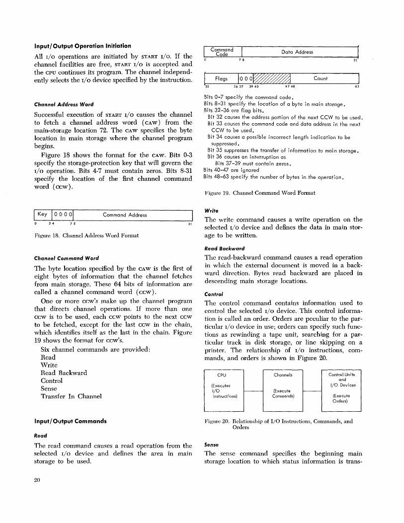
Input/Output Operation Initiation
All I/O operations are initiated by START I/O. If the channel facilities are free, START I/O is accepted and the CPU continues its program. The channel independently selects the I/O device specified by the instruction.
Channel Address Word
Successful execution of START I/O causes the channel to fetch a channel address word ( CAW) from the main-storage location 72. The CAW specifies the byte location in main storage where the channel program begins.
Figure 18 shows the format for the CAW. Bits 0-3 specify the storage-protection key that will govern the I/O operation. Bits 4-7 must contain zeros. Bits 8-31 specify the location of the first channel command word (Cc:W).
1 Key 100001 Command Address
o 34 7 8 31
Figure 18. Channel Address Word Format
Channel Command Word
The byte location specified by the CAW is the first of eight bytes of information that the channel fetches from main storage. These 64 bits of information are called a channel command word (CCw).
One or more ccw's make up the channel program that directs channel operations. If more than one ccw is to be used, each ccw points to the next ccw to be fetched, except for the last ccw in the chain, which identifies itself as the last in the chain. Figure 19 shows the format for ccw's.
Six channel commands are provided: Read Write Read Backward Control Sense Transfer In Channel
Input / OILJtput Commands
Read
The read command causes a read operation from the selected I/O device and defines the area in main storage to be used.
20
I Command Data Address Code 0 7 8
L Flags 1000~ Count
3637 3940 4748
Bits 0-7 specify the command code. Bits 8-31 specify the location of a byte in main storage. Bits 32-36 are flag bits.
J 63
Bit 32 causes the address portion of the next CCW to be used a
Bit 33 causes the command code and data address in the next CCW to be used.
Bit 34 causes a possible incorrect length indication to be suppressed.
Bit 35 suppresses the transfer of information to main storage. Bit 36 causes an interruption as
Bits 37-39 must contain zeros. Bits 40-47 are ignored Bits 48-63 specify the number of bytes in the operation a
Figure 19. Channel Command Word Format
Write
The write command causes a write operation on the selected I/O device and defines the data in main storage to be written.
Read Backward
The read-backward command causes a read operation in which the external document is moved in a backward direction. Bytes read backward are placed in descending main storage locations.
Control
The control command contains information used to control the selected I/O device. This control information is caned an order. Orders are peculiar to the particular I/O device in use; orders can specify such functions as rewinding a tape unit, searching for a particular track in disk storage, or line skipping on a printer. The relationship of I/O instructions, commands, and orders is shown in Figure 20.
CPU Channels Control Units and
(Executes I/O Devices
I/O (Execute f..---
Instructions) Commands) (Execute Orders)
Figure 20. Relationship of 110 Instructions, Commands, and Orders
Sense
The sense command specifies the beginning main storage location to which status information is trans-

ferred from the selected control unit. This sense data may be one or more bytes long. It provides detailed information concerning the selected I/O device, such as a stacker-full condition of a card reader or a fiIeprotected condition of a reel of magnetic tape on a tape unit. Sense data have a significance peculiar to the I/O device involved.
Transfer In Channel
The transfer-in-channel command specifies the location of the next ccw to be used by the channel whenever the programmer desires to break the existing chain of ccw's and cause the channel to begin fetching a new chain of ccw's from a different area in main storage.
External documents, such as punched cards or magnetic tape, may carry ccw's that the channel can use to govern reading of the external document being read.
Input / Output Termination
Input/output operations normally terminate with device-end signal and channel-end conditions and an interruption signal to the CPU.
A command can be rejected during execution of START I/O, however, by a busy condition, program check, etc. The rejection of the command is indicated in the condition code in the psw, and the details of the conditions that precluded initiation of the I/O operation are provided in the channel status word stored when the command is rejected.
Channel Status Word
The channel status word (csw) provides information about the termination of an I/O operation. It is formed or reformed by START I/O, TEST I/O, or by an I/O interruption. Figure 21 shows the csw format.
Command Address
o 34 7 8 31
Status Count
32 47 48 63
Bits 0-3 contains the storage-protection key used in the operation.
Bit 4-7 contain zeros. Bits 8-31 specify the location of the last CCW used. Bits 32-47 contain an I/O device-status byte and a channel
status byte. The status bytes provide such information as datacheck, chaining check, control-unit end, etc.
Bits 48-63 contain the residual count of the last CCW used.
Figure 21. Channel Status Word Format
Input / Output Interruptions
Input/output interruptions are caused by termination of an I/O operation or by operator intervention at the
I/O device. Input/output interruptions enable the CPU to provide appropriate programmed response to conditions that occur in I/O devices or channels.
Input/output interruptions have two priority sequences, one for the I/O devices attached to a channel, and another for channel interruptions. A channel establishes interruption priority for its associated I/O
devices before initiating an I/O interruption signal to the cpu. Conditions responsible for I/O interruption requests are preserved in the I/O devices or channels until they are accepted by the CPU.
System Control Panel The system control panel provides the switches, keys, and lights necessary to operate and control the system. The need for operator manipulation of manual controls is held to a minimum by the system design and the governing supervisory program. The result is fewer and less serious operator errors.
System Control Panel Functions
The main functions provided by the system control panel are the ability to: reset the system; store and display information in main storage, in registers, and in the psw; and load initial program information.
System Reset
The system-reset function resets the CPU, the channels, and online control units and I/O devices. In general, the system is placed in such a state that processing can be initiated without the occurrence of machine checks, except those caused by subsequent machine malfunction.
Store and Display
The store-and-display function permits manual intervention in the progress of a program. The function may be provided by a supervisory program in conjunction with proper I/O equipment and the interrupt key. Or, the system-control-panel facilities may be used to place the CPU in the stopped state, and then to store and display information in main storage, in general and floating-point registers, and in instructionaddress portion of the psw.
Initial Program Loading
The initial-program-Ioading (IPL) procedure is used to begin or renew system operation. The load key is pressed after an input device is selected with the loadunit switches. This causes a read operation at the selected input device. Six words of information are
System Structure 21

read into main storage and used as channel control words and as a psw that controls subsequent system operation.
The system controls are divided into three sections: operator control, operator intervention, and customer engineering control.
Operator Control Section
This section of the system control panel contains the operator controls required when the CPU is operating under supervisory program control.
The main functions provided are the control and indication of power, the indication of system status, and operator-to-machine communication. These include:
22
Emergency power-off pull switch Power-on back-lighted key Power-off key Interrupt key Wait light Manual light System light Test light
Load light Load-unit switches T.oad key
Operator Intervention Section
This section of the system control panel provides controls required for operator intervention into normal programmed operation. These include:
System reset key Stop key Start key Rate switch (single cycle or normal processing) Storage-select switches Address switches Data switches Store key Display key Set Ie key Address compare switches
Customer Engineering Section
This section of the system control panel provides the controls intended only for customer engineering use. Customer engineering controls are also available on some storage, channel, and control-unit equipment.
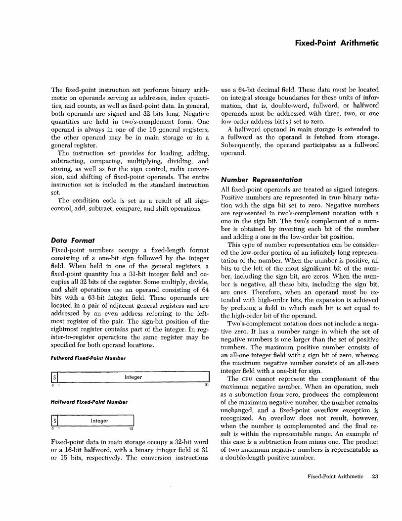
The fixed-point instruction set performs binary arithmetic on operands serving as addresses, index quantities, and counts, as well as fixed-point data. In general, both operands are signed and 32 bits long. Negative quantities are held in two's-complement form. One operand is always in one of the 16 general registers; the other operand may be in main storage or in a general register.
The instruction set provides for loading, adding, subtracting, comparing, multiplying, dividing, and storing, as well as for the sign control, radix conversion, and shifting of fixed-point operands. The entire instruction set is included in the standard instruction set.
The condition code is set as a result of all signcontrol, add, subtract, compare, and shift operations.
Data Format Fixed-point numbers occupy a fixed-length format consisting of a one-bit sign followed by the integer field. When held in one of the general registers, a fixed-point quantity has a 31-bit integer field and occupies all 32 bits of the register. Some multiply, divide, and shift operations use an operand consisting of 64 bits with a 63-bit integer field. These operands are located in a pair of adjacent general registers and are addressed by an even address referring to the leftmost register of the pair. The sign-bit position of the rightmost register contains part of the integer. In register-to-register operations the same register may be specified for both operand locations.
Fullword Fixed-Point Number
151 Integer
o 1 31
Halfword Fixed-Point Number
I s\ Integer
o 1 15
Fixed-point data in main storage occupy a 32-bit word or a 16-bit halfword, with a binary integer field of 31 or 15 bits, respectively. The conversion instructions
Fixed-Point Arithmetic
use a 64-bit decimal field. These data must be located on integral storage boundaries for these units of information, that is, double-word, fullword, or halfword operands must bc addressed with three, two, or one low-ordcr address bit ( s) set to zero.
A halfword operand in main storage is extended to a fullword as the operand is fetched from storage. Subsequently, the operand participates as a full word operand.
Number Representation All fixed-point operands are treated as signed integers. Positive numbers are represented in true binary notation with the sign bit set to zero. Negative numbers are represented in two's-complement notation with a one in the sign bit. The two's complement of a number is obtained by inverting each bit of the number and adding a one in the low-order bit position.
This type of number representation can be considered the low-order portion of an infinitely long representation of the number. When the number is positive, all bits to the left of the most significant bit of the number, including the sign bit, are zeros. When the number is negative, all these bits, including the sIgn bit, are ones. Therefore, when an operand must be extended with high-order bits, the expansion is achieved by prefixing a field in which each bit is set equal to the high-order bit of the operand.
Two's-complement notation does not include a negative zero. It has a number range in which the set of negative numbers is one larger than the set of positive numbers. The maximum positive number consists of an all-one integer field with a sign bit of zero, whereas the maximum negative number consists of an all-zero integer field with a one-bit for sign.
The CPU cannot represent the complement of the maximum negative number. When an operation, such as a subtraction from zero, produces the complement of the maximum negative number, the number remains unchanged, and a fixed-pOint overflow exception is recognized. An overflow does not result, however, when the number is complemented and the final resuIt is within the representable range. An example of this case is a subtraction from minus one. The product of two maximum negative numbers is representable as a double-length positive number.
Fixed-Point Arithmetic 23
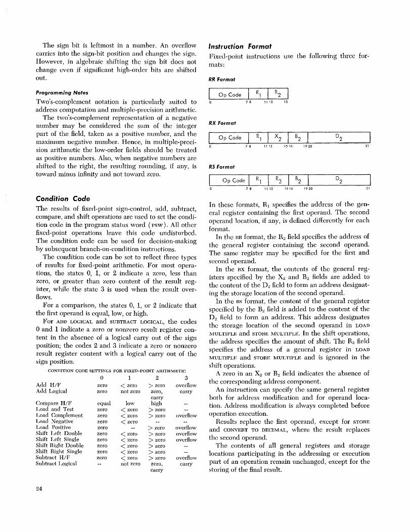
The sign bit is leftmost in a number. An overHow carries into the sign-bit position and changes the sign. However, in algebraic shifting the sign bit does not change even if significant high-order bits are shifted out.
Programming Notes
Two's-complement notation is particularly suited to address computation and multiple-precision arithmetic.
The two's-complement representation of a negative number may be considered the sum of the integer part of the field, taken as a positive number, and the maximum negative number. Hence, in multiple-precision arithmetic the low-order fields should be treated as positive numbers. Also, when negative numbers are shifted to the right, the resulting rounding, if any, is toward minus infinity and not toward zero.
Conditic)n Code The results of fixed-point sign-control, add, subtract, compare" and shift operations are used to set the condition code in the program status word (psw). All other fixed-point operations leave this code undisturbed. The condition code can be used for decision-making by subsequent branch-on-condition instructions.
The condition code can be set to reHect three types of results for fixed-point arithmetic. For most operations, the states 0, 1, or 2 indicate a zero, less than zero, or greater than zero content of the result register' while the state 3 is used when the result overHows.
For a comparison, the states 0, 1, or 2 indicate that the first operand is equal, low, or high.
For ADD LOGICAL and SUBTRACT LOGICAL, the codes ° and 1 indicate a zero or nonzero result register content in the absence of a logical carry out of thc sign position; the codes 2 and 3 indicate a zero or nonzero result register content with a logical carry out of the sign position.
CONDITION CODE SETTINGS FOR FIXED-POINT ARITHMETIC
0 1 2 3 Add H/F zero < zero > zero overflow Add Logical zero not zero zero, carry
carry Compare H/F equal low high Load and Test zero < zero > zero Load Complement zero < zero > zero overflow Load Negative zero < zero Load Positive zero > zero overflow Shift Left Double zero < zero > zero overflow Shift Left Single zero < zero > zero overflow Shift Right Double zero < zero > zero Shift Right Single zero < zero > zero Subtract H/F zero < zero > zero overflow Subtract Logical not zero zero, carry
carry
24
Instruction Format
Fixed-point instructions use the following three formats:
RR Format
7 8 11 12 15
RX Format
I Op Code Rl X2 B2
0 7 8 11 12 1516 1920 31
RS Format
Op Code Rl R3 B2
7 8 11 12 1516 1920 31
In these formats, RJ specifies the address of the general register containing the first operand. The second operand location, if any, is defined differently for each format.
In the HR format, the R2 field specifies the address of the general register containing the second operand. The same register may be specified for the first and second operand.
In the RX format, the contents of the general registers specified by the X2 and B2 fields are added to the content of the D2 field to form an address designating the storage location of the second operand.
In the RS format, the content of the general register specified by the B2 field is added to the content of the D.) field to form an address. This address designates th~ storage location of the second operand in LOAD
MULTIPLE and STORE MULTIPLE. In the shift operations, the address specifies the amount of shift. The R:~ field specifics the address of a general register in LOAD
MULTIPLE and STORE MULTIPLE and is ignored in the shift operations.
A zero in an X2 or B2 field indicates the absence of the corresponding address component.
An instruction can specify the same general register both for address modification and for operand location. Address modification is always completed before operation execution.
Results replace the first operand, except for STORE
and CONVERT TO DECIMAL, where the result replaces the second operand.
The contents of all general registers and storage locations participating in the addressing or execution part of an operation remain unchanged, except for the storing of the final result.

Instructions The fixed-point arithmetic instructions and their mne-monics, formats, and operation codes are listed in the following table. The table also indicates which instruc-tions are not included in the small binary instruction set, when the condition code is set, and the exceptional conditions that cause a program interruption.
NAME MNEMONIC
Load LR Load L Load Halfword LH Load and Test LTR Load Complement LCR Load Positive LPR Load Negative LNR Load Multiple LM Add AR Add A Add Halfword All Add Logical ALR Add Logical AL Subtract SR Subtract S Subtract Halfword SH Subtract Logical SLR Subtract Logical SL Compare CR Compare C Compare Halfword CH Multiply MR Multiply M Multiply Halfword MH Divide DR Divide D Convert to Binary CVB Convert to Decimal CVD Store ST Store Halfword STH Store Multiple STM Shift Left Single SLA Shift Right Single SRA Shilt Left Double SLDA Shift Right Double SRDA
Addressing exception Condition code is set Data exception
TYPE
RR RX RX RR RR RR RR RS RR RX RX RR RX RR RX RX RR RX RR RX RX RR RX RX RR RX RX RX RX RX RS RS RS RS RS
NOTES
A C D IF IK P S
Fixed-Point overflow exception Fixed-point divide exception Protection exception Specification exception
Programming Note
EXCEPTIONS
A,S A,S
C C IF C IF C
A,S C IF C A,S, IF C A,S, IF C C A,S C IF C A,S, IF C A,S, IF C C A,S C C A,S C A,S
S A,S A,S
S, IK A,S, IK A,S,D,IK
P,A,S P,A,S P,A,S P,A,S
C IF C C S, IF C S
CODE
18 58 48 12 13 10 11 98 lA 5A 4A IE 5E IB 5B 4B IF 5F 19 59 49 Ie 5C 4C ID 5D 4F 4E 50 40 90 8B 8A 8F 8E
The logical comparisons, shifts, and connectives, as well as LOAD ADDRESS, BRANCH ON COUNT, BRANCH ON
INDEX HIGH, and BRANCH ON INDEX LOW OR EQUAL, also may be used in fixed-point calculations.
Load
LR RR
I 18 R1 R2 0 7 8 11 12 15
L RX
I 58 R1 X2 B2 D2 0 7 8 11 12 1516 1920 31
The second operand is placed in the first operand location. The second operand is not changed.
Condition Code: The code remains unchanged. Program Interruptions:
Addressing (L only) Specification (L only)
Load Halfword
LH RX
48 7 8 11 12 15 16 1 9 20 31
The halfword second operand is placed in the first operand location.
The halfword second operand is expanded to a fullword by propagating the sign-bit value through the 16 high-order bit positions. Expansion occurs after the operand is obtained from storage and before insertion in the register.
Program Interruptions: Addressing Specification
Load and Test
LTR RR
12 7 8 11 12 15
The second operand is placed in the first operand location, and the sign and magnitude of the second operand determine the condition code. The second operand is not changed.
Fixed-Point Arithmetic 25

Resulting Condition Code: o Result is zero 1 Result is less than zero 2 Result is greater than zero 3
Program Interruptions: None.
Programming Note
When the same register is specified as first and second operand location, the operation is equivalent to a test without data movement.
Load Complement
LCR RR.
13 78 1112 15
The two's complement of the second operand is placed in the first operand location.
An overflow condition occurs when the maximum negative number is complemented; the number remains unchanged. The overflow causes a program interruption when the fixed-point overflow mask bit is one.
Resulting Condition Code: o Result is zero 1 Result is less than zero 2 Result is greater than zero 3 Overflow
Program Interruptions: Fixed-point overflow
Programming Note
Zero rema.ins invariant under complementation.
Load Posit'ive
LPR RR
10
78 1112 15
The absolute value of the second operand is placed in the first operand location.
The operation includes complementation of negative numbers; positive numbers remain unchanged.
An overflow condition occurs when the maximum negative number is complemented; the number remains unchanged. The overflow causes a program interruption when the fixed-point overflow mask bit is one.
26
Resulting Condition Code: o Result is zero 1 2 Result is greater than zero 3 Overflow
Program Interruptions: Fixed-point overflow
Load Negative
LNR RR
11 78 1112 15
The two's complement of the absolute value of the second operand is placed in the first operand location. The operation complements positive numbers; negative numbers remain unchanged. The number zero remains unchanged with positive sign.
Resulting Condition Code: o Result is zero 1 Rcsult is less than zero 2 3
Program Inten'uptions: None.
Load Multiple
LM RS
98 7 8 11 1 2 15 16 1 9 20 31
The set of general registers starting with the register specified by RI and ending with the register specified by Ra is loaded from the locations designated by the second opcrand address.
The storage area from which the contents of the general registers are obtained starts at the location designated by the second operand address and continues through as many words as needed. The general registers are loaded in the ascending order of their addresses, starting with the register specified by RI and continuing up to and including the register specified by Ra, with register 0 following register 15.
The second operand remains unchanged. Condition Code: The code remains unchanged. Program Interruptions:
Addressing Specification

Programming Note
All combinations of register addresses specified by Rl and Ra are valid. When the register addresses are equal, only one word is transmitted. When the address specified by Ra is less than the address specified by R1,
the register addresses wrap around from 15 to O.
Add
AR RR
lA 7 8 11 12 15
A RX
5A 7 8 11 12 15 16 1920 31
The second operand is added to the first operand, and the sum is placed in the first operand location.
Addition is performed by adding all 32 bits of both operands. If the carries out of the sign-bit position and the high-order numeric bit position agree, the sum is satisfactory; if they disagree, an overflow occurs. The sign bit is not changed after the overflow. A positive overflow yields a negative final sum, and a negative overflow results in a positive sum. The overflow causes a program interruption when the fixed-point overflow mask bit is one.
Resulting Condition Code: o Sum is zero 1 Sum is less than zero 2 Sum is greater than zero 3 Overflow
Program Interruptions: Addressing (A only) Specification (A only) Fixed-point overflow
Programming Note
In two's-complement notation, a zero result is always positive.
Add Halfword
AH RX
4A
7 8 11 12 15 16 1920 31
The halfword second operand is added to the first operand and the sum is placed in the first operand location.
The halfword second operand is expanded to a full-
word before the addition by propagating the sign-bit value through the 16 high-order bit positions.
Addition is performed by adding all 32 bits of both operands. If the carries out of the sign-bit position and the high-order numeric bit position agree, the sum is satisfactory; if they disagree, an overflow occurs. The sign bit is not changed after the overflow. A positive overflow yields a negative final sum, and a negative overflow results in a positive sum. The overflow causes a program interruption when the fixedpoint overflow mask bit is one.
Resulting Condition Code: o Sum is zero 1 Sum is less than zero 2 Sum is greater than zero 3 Overflow
Program Interruptions: Addressing Specification Fixed-point overflow
Add Logical
ALR RR
1 E
78 11 12 15
AL RX
5E 78 1112 1516 1920 31
The second operand is added to the first operand, and the sum is placed in the first operand location. The occurrence of a carry out of the sign position is recorded in the condition code.
Logical addition is performed by adding all 32 bits of both operands without further change to the resulting sign bit. The instruction differs from ADD in the meaning of the condition code and in the absence of the interruption for overflow.
If a carry out of the sign position occurs, the leftmost bit of the condition code (psw bit 34) is made one. In the absence of a carry, bit 34 is made zero. When the sum is zero, the rightmost bit of the condition code (psw bit 35) is made zero. A nonzero sum is indicated by a one in bit 35.
Resulting Condition Code: o Sum is zero (no carry) 1 Sum is not zero (no carry) 2 Sum is zero (carry) 3 Sum is not zero (carry)
Fixed-Point Arithmetic 27
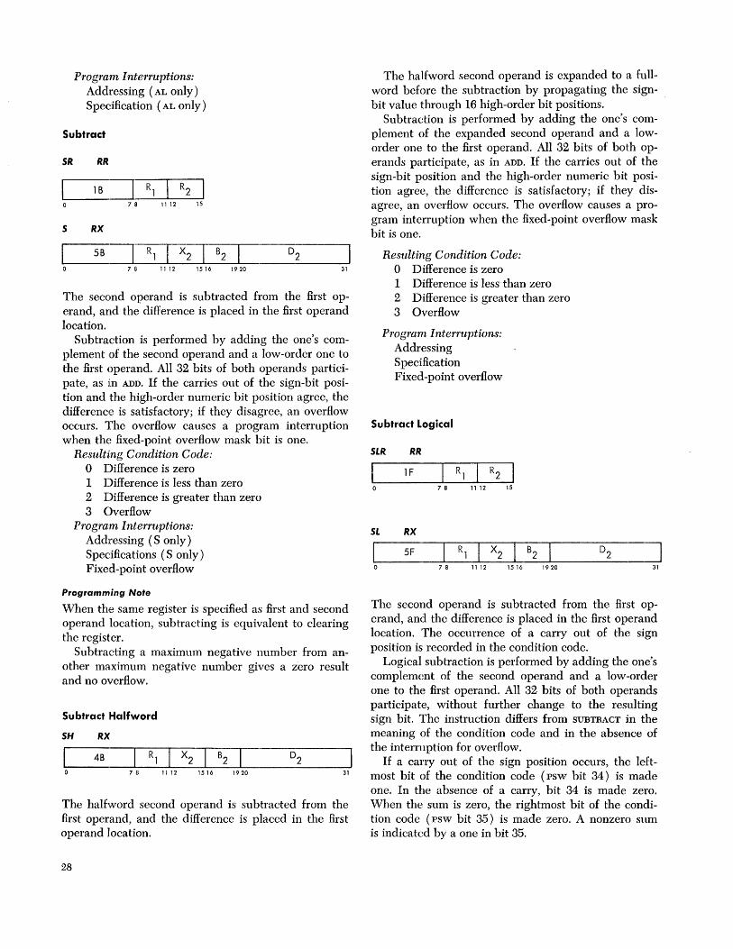
Program Interruptions: Addressing (AL only) Specification (AL only)
Subtract
SR RR
I 1B I R1 R2 0 78 11 12 15
S RX
I 5B I R1 X2 B2 D2 0 7 8 11 12 1516 1920 31
The second operand is subtracted from the first operand, and the difference is placed in the first operand location.
Subtraction is performed by adding the one's complement .of the second operand and a low-order one to the first operand. All 32 bits of both operands participate, as in ADD. If the carries out of the sign-bit position and the high-order numeric bit position agree, the difference is satisfactory; if they disagree, an overflow occurs. The overflow causes a program interruption when the fixed-point overflow mask bit is one.
ResulUng Condition Code: o Difference is zero 1 Difference is less than zero 2 Difference is greater than zero 3 Overflow
Program Interruptions: Addressing (S only) Specifications (S only) Fixed-point overflow
Programming Note
When the same register is specified as first and second operand location, subtracting is equivalent to clearing the register.
Subtracting a maximum negative number from another maximum negative number gives a zero result and no overflow.
Subtract :Halfword
SH RX
4B 7 8 11 12 15 16 1 9 20 31
The halfword second operand is subtracted from the first operand, and the difference is placed in the first operand location.
28
The halfword second operand is expanded to a fullword before the subtraction by propagating the signbit value through 16 high-order bit positions.
Subtraction is performed by adding the one's complement of the expanded second operand and a loworder one to the first operand. All 32 bits of both operands participate, as in ADD. If the carries out of the sign-bit position and the high-order numeric bit position agree, the difference is satisfactory; if they disagree, an overflow occurs. The overflow causes a program interruption when the fixed-point overflow mask bit is one.
Resulting Condition Code: o Difference is zero 1 Difference is less than zero 2 Difference is greater than zero 3 Overflow
Program Interruptions: Addressing S pecifica tion Fixed-point overflow
Subtract Logical
SLR RR
1 F 78 1112 15
SL RX
5F 7 8 11 1 2 15 16 1 9 20 31
The second operand is subtracted from the first operand, and the difference is placed in the first operand location. The occurrence of a carry out of the sign position is recorded in the condition code.
Logical subtraction is performed by adding the one's complement of the second operand and a low-order one to the first operand. All 32 bits of both operands participate, without further change to the resulting sign bit. The instruction differs from SUBTRACT in the meaning of the condition code and in the absence of the interruption for overflow.
If a carry out of the sign position occurs, the leftmost bit of the condition code (psw bit 34) is made one. In the absence of a carry, bit 34 is made zero. When the sum is zero, the rightmost bit of the condition code (psw bit 35) is made zero. A nonzero sum is indicated by a one in bit 35.

Resulting Condition Code: o 1 Difference is not zero (no carry) 2 Difference is zero (carry) 3 Difference is not zero (carry)
Program Interruptions: Addressing (SL only) Specification (SL only)
Programming Note
A zero difference cannot be obtained without a carry out of the sign position.
Compare
CR RR
I 19 R, R2 0 7 8 11 12 15
C RX
I 59 R, X2 B2 0 7 8 11 12 1516 1920 31
The first operand is compared with the second operand, and the result determines the setting of the condition code.
Comparison is algebraic, treating both comparands as 32-bit signed integers. Operands in registers or storage are not changed.
Resulting Condition Code: o Operands are equal 1 First operand is low 2 First operand is high 3
Program Interruptions: Addressing (C only) Specification (C only)
Compare Halfword
CH RX
49 7 8 11 12 15 16 1920 31
The first operand is compared with the halfword sec- ' ond operand, and the result determines the setting of the condition code.
The halfword second operand is expanded to a fullword before the comparison by propagating the signbit value through the 16 high-order bit positions.
Comparison is algebraic, treating both comparands as 32-bit signed integers. Operands in registers or storage are not changed.
Resulting Condition Code: o Operands are equal 1 First operand is low 2 First operand is high 3
Program Interruptions: Addressing Specification
Multiply
MR RR
1C 78 1112 15
M RX
5C 7 8 11 1 2 15 1 6 1 9 20
J 31
The product of the multiplier (the second operand) and the multiplicand (the first operand) replaces the multiplicand.
Both multiplier and multiplicand are 32-bit signed integers. The product is always a 64-bit signed integer and occupies an even/odd register pair. Because the multiplicand is replaced by the product, the Rl field of the instruction must refer to an even-numbered register. A specification exception occurs when Rl is odd. The multiplicand is taken from the odd register of the pair. The content of the even-numbered register replaced by the product is ignored, unless the register contains the multiplier. An overflow cannot occur.
The sign of the product is determined by the rules of algebra from the multiplier and multiplicand sign, except that a zero result is always positive.
Condition Code: The code remains unchanged. Program Interruptions:
Addressing (M only) Specification
Programming Note
The significant part of the product usually occupics 62 bits or fewer. Only when two maximum negative numbers are multiplied are 63 significant product bits formed. Since two's-complement notation is used, the sign bit is extended right until the first significant product digit is encountered.
Fixed-Point Arithmetic 29

Multiply Halfword
MH RX
7 8 11 12 15 16 1920 31
The product of the halfword multiplier (second operand) and multiplicand (first operand) replaces the multiplicand.
Both multiplicand and product are 32-bit signed integers and may be located in any general register. The half word multiplier is expanded to a fullword before multiplication by propagating the sign-bit value through the 16 high-order bit positions. The multiplicand is replaced by the low-order part of the product. The bits to the left of the 32 low-order bits are not tested for significance; no overflow indication is given.
The sign of the product is determined by the rules of algebra from the multiplier and multiplicand sign, except that a zero result is always positive.
Condition Code: The code remains unchanged. Program Interruptions:
Addressing S pecifica tion
Programming Note
The significant part of the product usually occupies 46 bits or fewer, the exception being 47 bits when both operands are maximum negative. Since the low-order 32 bits of the product are stored unchanged, ignoring all bits to the left, the sign bit of the result may differ from the true sign of the product in the case of overflow.
Divide
DR RR
1D 7 8 11 12 15
D RX
5D 7 8 11 1 2 15 16 1 9 20 31
The dividend (first operand) is divided by the divisor (second operand) and replaced by the quotient and remainder.
The dividend is a 64-bit signed integer and occupies the even/odd pair of registers specified by the Rl field of the instruction. A specification exception occurs
30
when Rl is odd. A 32-bit signed remainder and a 32-bit signed quotient replace the dividend in the even-numbered and odd-numbered registers, respectively. The divisor is a 32-bit signed integer.
The sign of the quotient is determined by the rules of algebra. The remainder has the same sign as the dividend, except that a zero quotient or a zero remainder is always positive. All operands and results are treated as signed integers. When the relative magnitude of dividend and divisor is such that the quotient cannot be expressed by a 32-bit signed integer, a fixed-point divide exception is recognized (a program interruption occurs, no division takes place, and the dividend remains unchanged in the gcneral registers) .
Condition Code: The code remains unchanged. Program Interruptions:
Addressing (D only) S pecifica tion Fixed-point divide
Programming Note
Division applies to fullword operands in storage only ..
Convert to Binary
eva RX
4F 7 8 11 12 15 16 1920 31
The radix of the second operand is changed from decimal to binary, and the result is placed in the first operand location. The number is treated as a rightaligned signed integer both before and after conversion.
The second operand has the packed decimal data format and is checked for valid sign and digit codes. Improper codes are a data exception and cause a program interruption. The decimal operand occupies a double-word storage field, which must be located on an integral boundary. The low-order four bits of the field represent the sign. The remaining 60 bits contain 15 binary-coded-decimal digits in true notation. The packed decimal data format is described under "Decimal Arithmetic."
The result of the conversion is placed in the general register specified by R l • The maximum number that can be converted and still be contained in a 32-bit register is 2,147,483,647; the minimum number is -2,147,483,648. For any decimal number outside this range, the operation is completed by placing the 32 low-order binary bits in the register; a fixed-point

divide exception exists, and a program interruption follows. In the case of a negative second operand, the low-order part is in two's-complement notation.
Condition Code: The code remains unchanged. Program Interruptions:
Addressing Specification Data Fixed-point divide
Convert to Decimal
eVD RX
4E 7 8 1 1 12 15 16 1 9 20 31
The radix of the first operand is changed from binary to decimal, and the result is stored in the second operand location. The number is treated as a rightaligned signed integer both before and after conversion.
The result is placed in the storage location designated by the second operand and has the packed decimal format, as described in "Decimal Arithmetic." The result occupies a double-word in storage and must be located on an integral boundary. The low-order four bits of the field represent the sign. A positive sign is encoded as 1100 or 1010; a negative sign is encoded as 1101 or 1011. The choice between the two sign representations is determined by the state of psw bit 12. The remaining 60 bits contain 15 binary-cod eddecimal digits in true notation.
The number to be converted is obtained as a 32-bit signed integer from a general register. Since 15 decimal digits are available for the decimal equivalent of 31 bits, an overflow cannot occur.
Condition Code: The code remains unchanged. Resulting Condition Code:
Protection Addressing Specification
Store
5T RX
I 50 Rl X2 B2 D2 0 7 8 11 12 1516 1920 31
The first operand is stored at the second operand location.
The 32 bits in the general register are placed unchanged at the second operand location.
Condition Code: The code remains unchanged. Program Interruptions:
Protection Addressing Specification
Store Halfword
5TH RX
40 7 8 11 12 15 16 1 9 20 31
The first operand is stored at the halfword second operand location.
The 16 low-order bits in the general register are placed unchanged at the second operand location. The 16 high-order bits of the first operand do not participate and are not tested.
Condition Code: The code remains unchanged. Program Interruptions:
Protection Addressing Specification
Store Multiple
5TM R5
90 78 11 12 1516 1920
The set of general registers starting with the register specified by Rl and ending with the register specified by R3 is stored at the locations designated by the second operand address.
The storage area where the contents of the general registers are placed starts at the location designated by the second operand address and continues through as many words as needed. The general registers are stored in the ascending order of their addresses, starting with the register specified by Rl and continuing up to and including the register specified by R3, with register 0 following register 15. The first operands remain unchanged.
Condition Code: The code remains unchanged. Program Interruptions:
Protection Addressing S pecifica tion
Fixed-Point Arithmetic 31
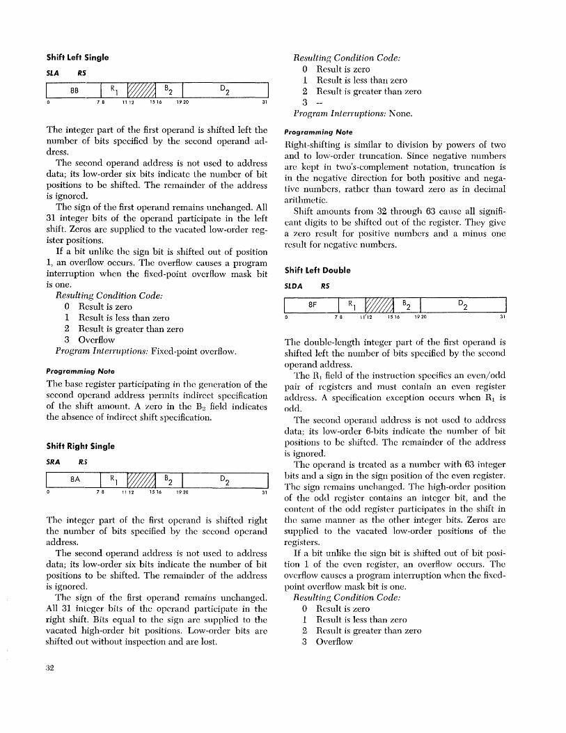
Shift Left Single
SLA RS
8B 7 8 11 12 1516 1920 31
The integer part of the first operand is shifted left the number OIf bits specified by the second operand address.
The second operand address is not used to address data; its low-order six bits indicate the number of bit positions to be shifted. The remainder of the address is ignored.
The sign of the first operand remains unchanged. All 31 integer bits of the operand participate in the left shift. Zeros are supplied to the vacated low-order register positions.
If a bit unlike the sign bit is shifted out of position 1, an overflow occurs. The overflow causes a program interruption when the fixed-point overflow mask bit is one.
Resulting Condition Code: o Result is zero 1 Result is less than zero 2 Result is greater than zero 3 Overflow
Program Interruptions: Fixed-point overflow.
Programming Note
The base register participating in the generation of the second operand address permits indirect specification of the shift amount. A zero in the B:! field indicates the absence of indirect shift specification.
Shift Right Single
SRA RS
8A
78 ]] 12 1516 1920 31
The integer part of the first operand is shifted right the num her of bits specified by the second operand address.
The second operand address is not used to address data; its low-order six bits indicate the number of bit positions to be shifted. The remainder of the address is ignored.
The sign of the first operand remains unchanged. All 31 integer bits of the operand participate in the right shift. Bits equal to the sign are supplied to the vacated high-order bit positions. Low-order bits are shifted out without inspection and are lost.
32
Resulting Condition Code: o Result is zero 1 Result is less than zero 2 Result is greater than zero 3
Program Interruptions: None.
Programming Note
Right-shifting is similar to division by powers of two and to low-order truncation. Since negative numbers are kept in two's-complement notation, truncation is in the negative direction for both positive and negative numbers, rather than toward zero as in decimal arithmetic.
Shift amounts from 32 through 63 cause all significant digits to be shifted out of the register. They give a zero result for positive numbers and a minus one result for negative numbers.
Shift Left Double
SLDA RS
8F
78 ]]/]2 1516 1920 31
The double-length integer part of the first operand is shifted left the number of bits specified by the second operand address.
The RL field of the instruction specifics an even/odd pair of registers and must contain an even register address. A specification exception occurs when Rl is odd.
The second operand address is not used to address data; its low-order 6-bits indicate the number of bit positions to be shifted. The remainder of the address is ignored.
The operand is treated as a number with 63 integer bits and a sign in the sign position of the even register. The sign remains unchanged. The high-order position of the odd register contains an integer bit, and the content of the odd register participates in the shift in the same manner as the other integer bits. Zeros are supplied to the vacated low-order positions of the registers.
If a bit unlike the sign bit is shifted out of bit position 1 of the even register, an overflow occurs. The overflow causes a program interruption when the fixedpoint overflow mask bit is one.
Resulting Condition Code: o Result is zero 1 Result is less than zero 2 Result is greater than zero 3 Overflow
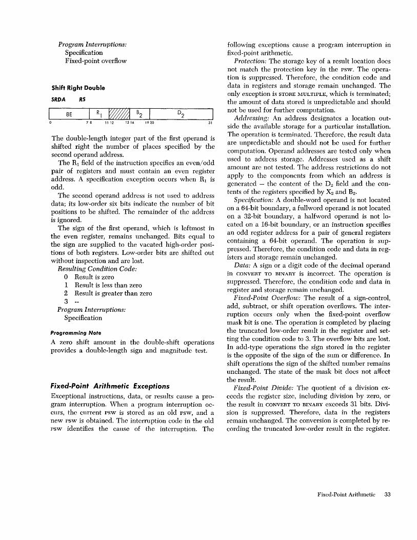
Program Interruptions: Specification Fixed-point overflow
Shift Right Double
SRDA RS
8E 78 1112 1516 1920 31
The double-length integer part of the first 9perand is shifted right the number of places specified by the second operand address.
The RI field of the instruction specifies an even/odd pair of registers and must contain an even register address. A specification exception occurs when RI is odd.
The second operand address is not used to address data; its low-order six bits indicate the number of bit positions to be shifted. The remainder of the address is ignored.
The sign of the first operand, which is leftmost in the even register, remains unchanged. Bits equal to the sign are supplied to the vacated high-order positions of both registers. Low-order bits are shifted out without inspection and are lost.
Resulting Condition Code: o Result is zero 1 Result is less than zero 2 Result is greater than zero 3
Program Interruptions: Specification
Programming Note
A zero shift amount in the double-shift operations provides a double-length sign and magnitude test.
fixed-Point Arithmetic Exceptions Exceptional instructions, data, or results cause a program interruption. When a program interruption occurs, the current psw is stored as an old PSW, and a new psw is obtained. The interruption code in the old psw identifies the cause of the interruption. The
following exceptions cause a program interruption in fixed-point arithmetic.
Protection: The storage key of a result location does not match the protection key in the psw. The operation is suppressed. Therefore, the condition code and data in registers and storage remain unchanged. The only exception is STORE MULTIPLE, which is terminated; the amount of data stored is unpredictable and should not be used for further computation.
Addressing: An address designates a location outside the available storage for a particular installation. The operation is terminated. Therefore, the result data are unpredictable and should not be used for further computation. Operand addresses are tested only when used to address storage. Addresses used as a shift amount are not tested. The address restrictions do not apply to the components from which an address is generated - thc content of the D2 field and the contents of the registers specified by X2 and B2 •
Specification: A double-word operand is not located on a 64-bit boundary, a fuIlword operand is not located on a 32-bit boundary, a halfword operand is not located on a 16-bit boundary, or an instruction specifies an odd register address for a pair of general registers containing a 64-bit operand. The operation is suppressed. Therefore, the condition code and data in registers and storage remain unchanged.
Data: A sign or a digit code of the decimal operand in CONVERT TO BINARY is incorrect. The operation is suppressed. Therefore, the condition code and data in register and storage rcmain unchanged.
Fixed-Point Overflow: The result of a sign-control, add, subtract, or shift operation overflows. The interruption occurs only when the fixed-point overflow mask bit is one. The operation is completed by placing the truncated low-order result in the register and setting the condition code to 3. The overflow bits are lost. In add-type operations the sign stored in the register is the opposite of the sign of the sum or difference. In shift operations the sign of the shifted number remains unchanged. The state of the mask bit docs not affect the result.
Fixed-Point Divide: The quotient of a division exceeds the register size, including division by zero, or the result in CONVERT TO BINARY exceeds 31 bits. Division is suppressed. Therefore, data in the registers remain unchanged. The conversion is completed by recording the truncated low-order result in the register.
Fixed-Point Arithmetic 33

Decimal Arithmetic
Decimal arithmetic operates on data in the packed format. In this format, two decimal digits are placed in one eight-bit byte. Since data are often communicated to or from external devices in the zoned format (which has one digit in an eight-bit byte), the necessary format-conversion operations are also provided in this instruction group.
Data are interpreted as integers, right-aligned in their fields. They are kept in true notation with a sign in the low-order eight-bit byte.
Processing takes place right to left between mainstorage locations. All decimal arithmetic instructions use a two-address format. Each address specifics the leftmost byte of an operand. Associated with this address is a length field, indicating the number of additional bytes that the operand extends beyond the first byte.
The decimal arithmetic instruction set provides for adding, subtracting, comparing, multiplying, and dividing, as well as the format conversion of variablelength operands. Most decimal instructions are part of the decimal feature.
The condition code is set as a result of all add-type and comparison operations.
Data Format
Decimal operands reside in main storage only. They occupy Helds that may start at any byte address and are composed of one to 16 eight-bit bytes.
Lengths of the two operands specified in an instruction need not be the same. If necessary they are considered to be extended with zeros to the left of the high-order digits. Results never exceed the limits set by address and length specification. Lost carries or lost digits from arithmetic operations are signaled as a decimal overflow exception. Operands arc either in the packed or zoned format.
Packed Decimal Number
I Digit I Digit I Digit [~~ ~-J Digit I Digit I Digit I Digit I Sign I
In the packed format, two decimal digits normally are placed adjacent in a byte, except for the rightmost byte of the field. In the rightmost byte a sign is placed
34
to the right of decimal digit. Both digits and a sign arc encoded and occupy four bits each.
Zoned Decimal Number
I Zone I Digit I Zone [-_- ~~] Digit I Zone I Digit I Sign I~
In the zoned format the low-order four bits of a byte, the numeric, are normally occupied by a decimal digit. The four high-order bits of a byte are called the zone, except for the rightmost byte of the field, where normally the sign occupies the zone position.
Arithmetic is performed with operands and results in the packed format. In the zoned format, the digits are represented as part of an alphameric character set. A PACK instruction is provided to transform zoned data into packed data, an an UNPACK instruction performs the reverse transformation. Moreover, the editing instructions may be used to change data from packed to zoned.
The fields specified in decimal arithmetic other than in PACK, UNPACK, and MOVE WITH OFFSET either should not overlap at all or should have coincident rightmost bytes. In ZERO AND ADD, the destination field may also overlap to the right of the source field. Because the code configurations for digits and sign are verified during arithmetic, improper overlapping fields are recognized as data exceptions. In move-type operations, the operand digits and signs are not checked, and the operand fields may overlap without any restrictions.
The rules for overlapped fields are established for the case where operands are fetched right to left from storage, eight bits at a time, just before they are processed. Similarly, the results are placed in storage, eight bits at a time, as soon as they are generated. Actual processing procedure may be considerably different because of the use of preferred storage for intermediate results. Nevertheless, the same rules are observed.
Number Representation Numbers are represented as right-aligned true integers with a plus or minus sign.
The digits 0-9 have the binary encoding 0000-1001. The codes 1010-1111 are invalid as digits. This set of

codes is interpreted as sign codes, with 1010, 1100, 1110, and 1111 recognized as plus and with 1011 and 1101 recognized as minus. The codes 0000-1001 are invalid as sign codes. The zones are not tested for valid codes as they are eliminated in changing data from the zoned to the packed format.
The sign and zone codes generated for all decimal arithmetic results differ for the extended binary-codeddecimal interchange code (EBCDIC) and the American Standard code for information interchange ( ASCII) .
The choice between the two codes is determined by bit 12 of the psw. When bit 12 is zero, the preferred EBCDIC codes are generated; these are plus, 1100; minus, 1101; and zone, 1111. When bit 12 is one, the preferred ASCII codes are generated; these are plus, 1010; minus, 1011; and zone, 0101.
Condition Code The results of all add-type and comparison operations are used to set the condition code. All other decimal arithmetic operations leave the code unchanged. The condition code can be used for deciSion-making by subsequent branch-on-condition instructions.
The condition code can be set to reflect two types of results for decimal arithmetic. For most operations the states 0, 1, and 2 indicate a zero, less than zero, and greater than zero content of the result field; the state 3 is used when the result of the operations overflows.
For the comparison operation, the states 0, 1, and 2 indicate that the first operand compared equal, low, or high.
CONDITION CODE SETTING FOR DECIMAL ARITHMETIC
0 1 2 3 Add Decimal zero < zero > zero overflow Compare Decimal equal low high Subtract Decimal zero < zero > zero overflow Zero and Add zero < zero > zero overflow
Instruction Format Decimal instructions use the following format:
55 Format
Op Code B1 I ~? D1 I B2 1~[5] 7 8 11 12 1516 1920 31 32 35 36 47
For this format, the contents of the general register specified by Bl is added to the content of the Dl field to form an address. This address specifies the leftmost byte of the first operand field. The number of operand bytes to the right of this byte is specified by the Ll field of the instruction. Therefore, the length in bytes of the first operand field is 1-16, corresponding to a
length code in Ll of 0000-1111. The second operand field is specified similarly by the L 1, B2, and D2 instruction fields.
A zero in the Bl or B2 field indicates the absence of the corresponding address component.
Results of operations are always placed in the first operand field. The result is never stored outside the field specified by the address and length. In the event the first operand is longer than the second, the second operand is extended with high-order zeros up to the length of the first operand. Such extension never modifies storage. The second operand field and the contents of all general registers remain unchanged.
Instructions The decimal arithmetic instructions and their mnemonics and operation codes follow. All instructions use the ss format and assume packed operands and results. The only exceptions are PACK, which has a zoned operand, and UNPACK, which has a zoned result. The table indicates the feature to which each instruction belongs, when the condition code is set, and the exception that causes a program interruption.
NAME MNEMONIC
Add Decimal AP Subtract Decimal SP Zero and Add ZAP Compare Decimal CP Multiply Decimal MP Divide Decimal DP Pack PACK Unpack UNPK Move with Offset MVO
NOTES
Addressing exception Condition code is set
TYPE
SS T,C SS T,C SS T,C SS T,C SS T SS T SS SS SS
A C D DF DK P S T
Data exception Decimal-overflow exception Decimal-divide exception Protection exception Specification exception Decimal feature
Programming Note
EXCEPTIONS CODE
P,A, D,DF FA P,A, D,DF FB P,A, D,DF F8
A, D F9 P,A,S,D FC P,A,S,D,DK FD P,A F2 P,A F3 P,A Fl
The moving, editing, and logical comparing instructions may also be used in decimal calculations.
Add Decimal
AP 55
FA B1 I ~? D1 1 B2 IJ[5] 7 8 11 12 1516 1920 31 32 35 36 47
The second operand is added to the first operand, and the sum is placed in the first operand location.
Decimal Arithmetic 35
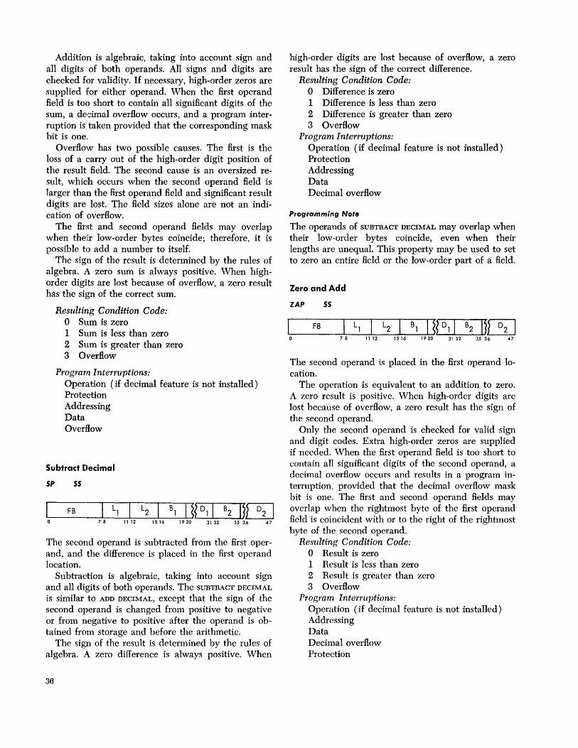
Addition is algebraic, taking into account sign and all digits of both operands. All signs and digits are checked for validity. If necessary, high-order zeros are supplied for either operand. When the first operand field is too short to contain all significant digits of the sum, a decimal overflow occurs, and a program interruption is taken provided that the corresponding mask bit is one.
Overflow has two possible causes. The first is the loss of a carry out of the high-order digit position of the result field. The second cause is an oversized result, which occurs when the second operand field is larger than the first operand field and significant result digits are lost. The field sizes alone are not an indication of overflow.
The first and second operand fields may overlap when their low-order bytes coincide; therefore, it is possible to add a number to itself.
The sign of the result is determined by the rules of algebra. A zero sum is always positive. When highorder digits are lost because of overflow, a zero result has the sign of the correct sum.
Resulting Condition Code: o Sum is zero 1 Sum is less than zero 2 Sum is greater than zero 3 Overflow
Program Interruptions: Operation (if decimal feature is not installed) Protection Addressing Data Overflow
Subtract [»ecimal
5P 55
FB 78 11 12 1516
The second operand is subtracted from the first operand, and the difference is placed in the first operand location.
Subtraction is algebraic, taking into account sign and all digits of both operands. The SUBTRACf DECIMAL
is similar to ADD DECIMAL, except that the sign of the second operand is changed from positive to negative or from negative to positive after the operand is obtained from storage and before the arithmetic.
The sign of the result is determined by the rules of algebra. A zero difference is always positive. When
36
high-order digits are lost because of overflow, a zero result has the sign of the correct difference.
Resulting. Condition Code: o Difference is zero 1 Difference is less than zero 2 Difference is greater than zero 3 Overflow
Program Interruptions: Operation (if decimal feature is not installed) Protection Addressing Data Decimal overflow
Programming Note
The operands of SUBTRACT DECIMAL may overlap when their low-order bytes coincide, even when their lengths are unequal. This property may be used to set to zero an entire field or the low-order part of a ReId.
Zero and Add
ZAP 55
F8 78 11 12 1516
The second operand is placed in the first operand location.
The operation is equivalent to an addition to zero. A zero result is positive. When high-order digits are lost because of overflow, a zero result has the sign of the second operand.
Only the second operand is checked for valid sign and digit codes. Extra high-order zeros are supplied if needed. When the Rrst operand Reld is too short to contain all significant digits of the second operand, a decimal overflow occurs and results in a program interruption, provided that the decimal overflow mask bit is one. The Rrst and second operand fields may overlap when the rightmost byte of the first operand field is coincident with or to the right of the rightmost byte of the second operand.
Resulting Condition Code: o Result is zero 1 Result is less than zero 2 Result is greater than zero 3 Overflow
Program Interruptions: Operation (if decimal feature is not installed) Addressing Data Decimal overflow Protection

Compare Decimal
CP 55
F9 B1 I ~? D1 I B2 IJ[5J 7 8 11 12 1516 1920 3132 35 36 47
The first operand is compared with the second, and the condition code indicates the comparison result.
Comparison is right to left, taking into account the sign and all digits of both operands. All signs and digits are checked for validity. If the fields are unequal in length, the shorter is extended with highorder zeros. A positive zero compares equal to a negative zero. Neither operand is changed as a result of the operation. Overflow cannot occur in this operation.
The first and second fields may overlap when their low-order bytes coincide. It is possible, therefore, to compare a number to itself.
Resulting Condition Code: o Operands equal 1 First operand is low 2 First operand is high 3
Program Interruptions: Operation (if decimal feature is not installed) Addressing Data
Programming Note
The COMPARE DECIMAL is unique in processing from right to left; taking signs, zeros, and invalid characters into account; and extending variable-length fields when they are unequal in length.
Multiply Decimal
MP 55
Fe 78 11 12 1516
The product of the multiplier (the second operand) and the multiplicand (the first operand) replaces the multiplicand.
The multiplier size is limited to 15 digits and sign and must be less than the multiplicand size. Length code L2, larger than seven, or larger than or equal to the length code Ll, is recognized as a specification exception. The operation is suppressed and a program interruption occurs.
Since the number of digits in the product is the sum of the number of digits in the operands, the multiplicand must have high-order zero digits for at least a field size that equals the multiplier field size; other-
wise, a data exception is recognized, and a program interruption occurs. This definition of the multiplicand field ensures that no product overflow can occur. The maximum product size is 31 digits. At least one highorder digit of the product field is zero.
All operands and results are treated as signed integers, right-aligned in their field. The sign of the product is determined by the rules of algebra from the multiplier and multiplicand signs, even if one or both operands are zero.
The multiplier and product fields may overlap when their low-order bytes coincide.
Condition Code: The code remains unchanged. Program Inte1'ruptions:
Operation (if decimal feature is not installed) Addressing Protection Specification Data
Programming Note
When the multiplicand does not have the desired number of leading zeros, multiplication may be preceded by a ZERO AND ADD into a larger field.
Divide Decimal
DP 55
FD 7 8 11 12 1516
The dividend (the first operand) is divided by the divisor (the second operand) and replaced by the quotient and remainder.
The quotient field is placed leftmost in the first operand field. The remainder field is placed rightmost in the first operand field and has a size equal to the divisor size. Together, the quotient and remainder occupy the entire dividend field; therefore, the address of the quotient field is the address of the first operand. The size of the quotient field in eight-bit bytes is Ll - L2, and the length code for this field is one less (Ll - L2 - 1). When the divisor length code is larger than seven (15 digits and sign) or larger than or equal to the dividend length code, a specification exception is recognized. The operation is suppressed, and a program interruption occurs.
The dividend, divisor, quotient, and remainder are all signed integers, right-aligned in their fields. The sign of the quotient is determined by the rules of algebra from dividend and divisor signs. The sign of the remainder has the same value as the dividend sign. These rules are true even when quotient or remainder is zero.
Decimal Arithmetic 37
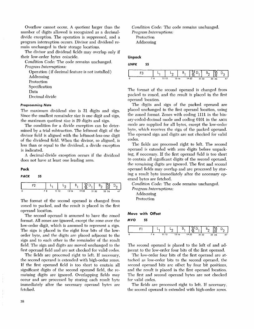
Overflow cannot occur. A quotient larger than the number of digits allowed is recognized as a decimaldivide exception. The operation is suppressed, and a program interruption occurs. Divisor and dividend remain unchanged in their storage locations.
The divisor and dividend fields may overlap only if their low··order bytes coincide.
Condition Code: The code remains unchanged. Program Interruptions:
Operation (if decimal feature is not installed) Addressing Protection Specification Data Decimal divide
Programming Note
The maximum dividend size is 31 digits and sign. Since the smallest remainder size is one digit and sign, the maximum quotient size is 29 digits and sign.
The condition for a divide exception can be determined by a trial subtraction. The leftmost digit of the divisor field is aligned with the leftmost-less-one digit of the dividend field. When the divisor, so aligned, is less than or equal to the dividend, a divide exception is indicated.
A decimal-divide exception occurs if the dividend does not have at least one leading zero.
Pack
PACK 55
F2 7 8 11 12 1516
The format of the second operand is changed from zoned to packed, and the result is placed in the first operand location.
The second operand is assumed to have the zoned format. All zones are ignored, except the zone over the low-order digit, which is assumed to represent a sign. The sign is placed in the right four bits of the loworder byte, and the digits are placed adjacent to the sign and to each other in the remainder of the result field. The sign and digits are moved unchanged to the first operand field and are not checked for valid codes.
The fields are processed right to left. If necessary, the second operand is extended with high-order zerO's. If the first operand field is too short to contain all significant digits of the second operand field, the remaining digits are ignored. Overlapping fields may occur and are processed by storing each result byte immediately after the necessary operand bytes are fetched.
38
Condition Code: The code remains unchanged. Program Interruptions:
Protection Addressing
Unpack
UNPK SS
F3 7 8 11 12 1516
The format of the second operand is changed from packed to zoned, and the result is placed in the first aperand lacation.
The digits and sign of the packed operand are placed unchanged in the first operand location, using the zoned format. Zones with coding 1111 in the binaJ'y-coded-decimal mode and coding 0101 in the ASCII
made are supplied for all bytes, except the low-order byte, which receives the sign of the packed operand. The operand sign and digits are not checked for valid codes.
The fields are processed right to left. The second operand is extended with zero digits before unpacking, if necessary. If the first operand field is too short to contain all significant digits of the second operand, the remaining digits are ignored. The first and second operand fields may overlap and are processed by storing a result byte immediately after the necessary operand bytes are fetched.
Condition Code: The code remains unchanged. Program Interruptions:
Addressing Protection
Move with Offset
MVO 55
~ __ Fl __ ~L_l~I~L2~_B~1 ~1~J?~~Dl~I_B_2~1~~ 7 8 11 12 15 16 1920 31 32 35 36 47
The second operand is placed to the left of and adjacent to the low-order four bits of the first operand.
The low-order four bits of the first operand are attached as low-order bits to the second operand, the second operand bits are offset by four bit positions, and the result is placed in the first operand location. The first and second operand bytes are not checked for valid codes.
The fields are processed right to left. If necessary, the second operand is extended with high-order zerO's.
If the first operand field is too short to contain all bytes of the second operand, the remaining information is ignored. Overlapping fields may occur and are processed by storing a result byte as soon as the necessary operand bytes are fetched.
Condition Code: The code remains unchanged. Program Interruptions:
Protection Addressing
Programming Note
The instruction set for decimal arithmetic includes no shift instructions since the equivalent of a shift can be obtained by programming. Programs for right or left shift and for an even or odd shift amount may be written with MOVE WITn OFFSET and the logical move instructions.
Decimal Arithmetic Exceptions
Exceptional instructions, data, or results cause a program interruption. When the interruption occurs, the current psw is stored as an old PSW, and a new psw is obtained. The interruption code in the old psw identifies the cause of the interruption. The following exceptions cause a program interruption in decimal arithmetic.
Operation: The decimal feature is not installed and the instruction is ADD DECIMAL, SUBTRACT DECIMAL,
ZERO AND ADD, COMPARE DECIMAL, MULTIPLY DECIMAL,
or DIVIDE DECIMAL. The instruction is suppressed. Therefore, the condition code and data in storage and registers remain unchanged.
Protection: The storage key of a result location does not match the protection key in the psw.
Addressing: An address designates a location outside the available storage for the installed system.
In the two preceding exceptions, the operation is terminated. The result data and the condition code are unpredictable and should not be used for further computation.
These address exceptions do not apply to the components from which an address is generated - the contents of the Dl and D2 fields and the contents of the registers specified by Bl and B2 •
Specifications: A multiplier or a divisor size exceeds 15 digits and sign or exceeds the multiplicand or dividend size. The instruction is suppressed; therefore, the condition code and data in storage and registers remain unchanged.
Data: A sign or digit code of an operand in ADD
DECIMAL, SUBTRACT DECIMAL, ZERO AND ADD, COMPARE
DECIMAL, MULTIPLY DECIMAL, or DIVIDE DECIMAL is incorrect, a multiplicand has insufficient high-order zeros, or the operand fields in these operations overlap incorrectly. The operation is terminated. The result data and the condition code are unpredictable and should not be used for further computation.
Decimal Overflow: The result of ADD DECIMAL, SUB
TRACT DECIMAL, or ZERO AND ADD overflows. The program interruption occurs only when the decimal-overflow mask bit is one. The operation is completed by placing the truncated low-order result in the result field and setting the condition code to 3. The sign and low-order digits contained in the result field are the same as they would have been for an infinitely long result field.
Decimal Divide Check: The quotient exceeds the specified data field, including division by zero. Division is suppressed. Therefore, the dividend and divisor remain unchanged in storage.
Decimal Arithmetic 39
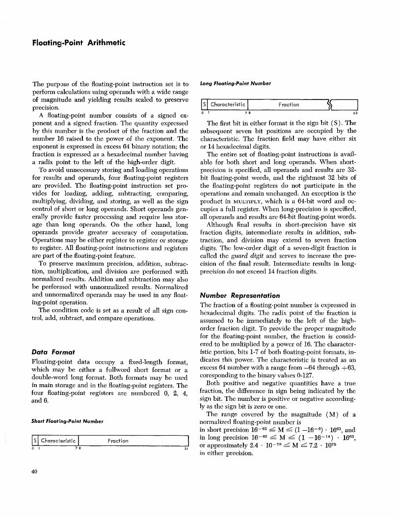
Floati nSI-Poi nt Arith metic
The purpose of the floating-point instruction set is to perform calculations using operands with a wide range of magnitude and yielding results scaled to preserve precision.
A floating-point number consists of a signcd exponent and a signed fraction. The quantity expressed by this number is the product of the fraction and the number 16 raised to the power of the exponent. The exponent is expressed in excess 64 binary notation; the fraction is expressed as a hexadecimal number having a radix point to the left of the high-order digit.
To avoid unnecessary storing and loading operations for results and operands, four floating-point registers are provided. The floating-point instruction set provides for loading, adding, subtracting, comparing, multiplying, dividing, and storing, as well as the sign control of short or long operands. Short operands generally provide faster processing and require less storage than long operands. On the other hand, long operands provide greater accuracy of computation. Operations may be either register to register or storage to register. All floating-point instructions and registers are part of the floating-point feature.
To preserve maximum precision, addition, subtraction, multiplication, and division are performed with normalized results. Addition and subtraction may also be performed with unnormalized results. Normalized and unnormalized operands may be used in any floating-point operation.
The condition code is set as a result of all sign control, add, subtract, and compare operations.
Data Format Floating-point data occupy a fixed-length format, which may be either a fullword short format or a double-word long format. Both formats may be used in main storage and in the floating-point registers. The four floating-point registers are numbered 0, 2, 4, and 6.
Short Floating-Point Number
Is I Characteristic I Fraction o I 78 31
40
Long Floating-Point Number
~ls~I~C_h_a_ra_c_t_e_ri_st_iC-LI _________ Fr_a_c_ti_o_n ______ ~SS~ ____ ~ o I 7 8 63
The first bit in either format is the sign bit (S). The subsequent seven bit positions are occupied by the characteristic. The fraction field may have either six or 14 hexadecimal digits.
The entire set of floating-point instructions is available for both short and long operands. When shortprecision is specified, all operands and results are 32-bit floating-point words, and the rightmost 32 bits of the floating-point registers do not participate in the operations and remain unchanged. An exception is the product in MULTIPLY, which is a 64-bit word and occupies a full register. When long-precision is specified, all operands and results are 64-bit floating-point words.
Although final results in short-precision have six fraction digits, intermediate results in addition, subtraction, and division may extend to seven fraction digits. Thc low-order digit of a seven-digit fraction is called the guard digit and serves to increase the precision of the final result. Intermediate results in longprecision do not exceed 14 fraction digits.
Number Representation The fraction of a floating-point number is expressed in hexadecimal digits. The radix point of the fraction is assumed to be immediately to the left of the highorder fraction digit. To provide the proper magnitude for the floating-point number, the fraction is considered to be multiplied by a power of 16. The characteristic portion, bits 1-7 of both floating-point formats, indicates this power. The characteristic is treated as an excess 64 number with a range from -64 through +63, coresponding to the binary values 0-127.
Both positive and negative quantities have a true fraction, the difference in sign being indicated by the sign bit. The number is positive or negative accordingly as the sign bit is zero or one.
The range covered by the magnitude (M) of a normalized floating-point number is in short preciSion 16-65 L. M L. (1 -16- 6) • 1663, and in long precision 16-65 L. M L. (1 -16-14 ) • 1663,
or approximately 2.4 . 10-78 L. M L. 7.2 . 1075
in either precision.
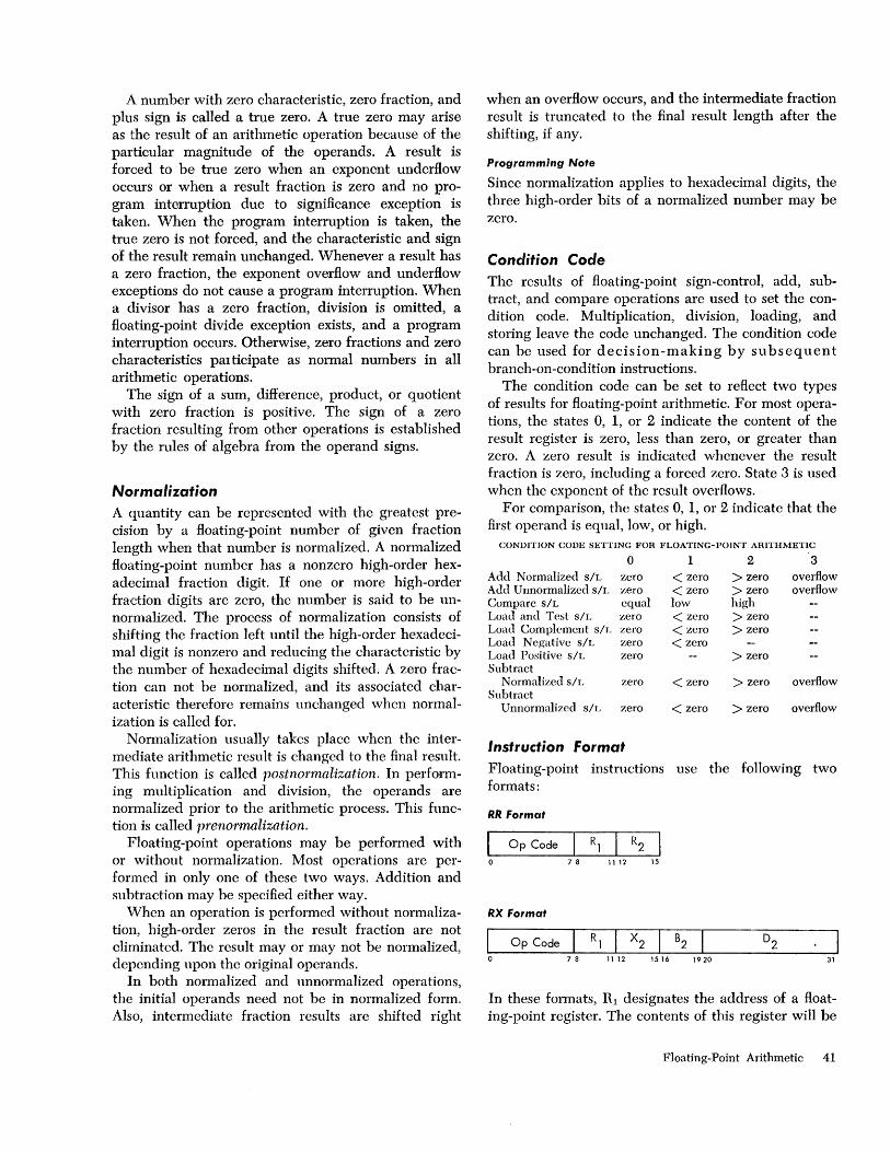
A number with zero characteristic, zero fraction, and plus sign is called a true zero. A true zero may arise as the result of an arithmetic operation because of the particular magnitude of the operands. A result is forced to be true zero when an exponent underflow occurs or when a result fraction is zero and no program interruption due to significance exception is taken. When the program interruption is taken, the true zero is not forced, and the characteristic and sign of the result remain unchanged. Whenever a result has a zero fraction, the exponent overflow and underflow exceptions do not cause a program interruption. When a divisor has a zero fraction, division is omitted, a floating-point divide exception exists, and a program interruption occurs. Otherwise, zero fractions and zero characteristics participate as normal numbers in all arithmetic operations.
The sign of a sum, difference, product, or quotient with zero fraction is positive. The sign of a zero fraction resulting from other operations is established by the rules of algebra from the operand signs.
Normalization A quantity can be represented with the greatest precision by a floating-point number of given fraction length when that number is normalized. A normalized floating-point number has a nonzero high-order hexadecimal fraction digit. If one or more high-order fraction digits are zero, the number is said to be unnormalized. The process of normalization consists of shifting the fraction left until the high-order hexadecimal digit is nonzero and reducing the characteristic by the number of hexadecimal digits shifted. A zero fraction can not be normalized, and its associated characteristic therefore remains unchanged when normalization is called for.
Normalization usually takes place when the intermediate arithmetic result is changed to the final result. This function is called postnol'malization. In performing multiplication and division, the operands are normalized prior to the arithmetic process. This function is called prenol'malization.
Floating-point operations may be performed with or without normalization. Most operations are performed in only one of these two ways. Addition and subtraction may be specified either way.
When an operation is performed without normalization, high-order zeros in the result fraction are not eliminated. The result mayor may not be normalized, depending upon the original operands.
In both normalized and unnormalizcd operations, the initial operands need not be in normalized form. Also, intermediate fraction results are shifted right
when an overflow occurs, and the intermediate fraction result is truncated to the final result length after the shifting, if any.
Programming Note
Since normalization applies to hexadecimal digits, the three high-order bits of a normalized number may be zero.
Condition Code The results of floating-point sign-control, add, subtract, and compare operations are used to set the condition code. Multiplication, division, loading, and storing leave the code unchanged. The condition code can be used for dec i s ion -m a kin g by sub seq u e n t branch-on-condition instructions.
The condition code can be set to reflect two types of results for floating-point arithmetic. For most operations, the states 0, 1, or 2 indicate the content of the result register is zero, less than zero, or greater than zero. A zero result is indicated whenever the result fraction is zero, including a forced zero. State 3 is used when the exponent of the result overflows.
For comparison, the states 0, 1, or 2 indicate that the first operand is equal, low, or high.
CONDITION CODE SETTING FOR FLOATING-POINT ARITHMETIC
0 Add Normalized S/L zero Add Unnormalized slL zero Compare S/L equal Load and Test S/L zero Load Complement S/L zero Load Negative s/L zero Load Positive S/L zero Subtract
Normalized S/L zero Subtract
Un normalized S/L zero
Instruction format
1 < zero < zero low < zero < zero < zero
< zero
< zero
2
> zero > zero high > zero > zero
> zero
> zero
> zero
3 overflow overflow
overflow
overflow
Floating-point instructions use the following two formats:
RR Format
I Op Code R, R2 o 78 1112 15
RX Format
I Op Code R, X2 B2 o 7 8 11 12 15 16 1 9 20 31
In these formats, Rl designates the address of a floating-point register. The contents of this register will be
Floating-Point Arithmetic 41
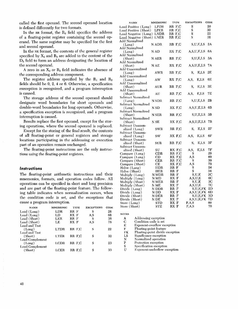
called the first operand. The second operand location is defined differently for two formats.
In the BB format, the R2 field specifies the address of a floating-point register containing the second operand. The same register may be specified for the first and second operand.
In the BX format, the contents of the general register specified by X2 and B2 arc added to the content of the D2 field to form an address designating the location of the second operand.
A zero in an X2 or B2 field indicates the absence of the corresponding address component.
The register address specified by the Rl and R2 fields should be 0, 2, 4 or 6. Otherwise, a specification exeception is recognized, and a program interruption is caused.
The storage address of the second operand should designate word boundaries for short operands and double-word boundaries for long operands. Otherwise, a specification exception is recognized, and a program interruption is caused.
Results replace the first operand, except for the storing operations, where the second operand is replaced.
Except for the storing of the final result, the contents of all floating-point or general registers and storage locations participating in the addressing or execution part of an operation remain unchanged.
The floating-point instructions are the only instructions using the floating-point registers.
Instructi,ons The floating-point arithmetic instructions and their mnemonics, formats, and operation codes follow. All operations can be specified in short and long precision and are part of the floating-point feature. The following table indicates when normalization occurs, when the condition code is set, and the exceptions that cause a program interruption.
NAME
Load (Long) Load (Long) Load (Short) Load (Short) Load and Test
(Long) Load and Test
(Short) Load Complement
(Long) Load Complement
(Short)
42
MNEMONIC
LDR LD LER LE
LTDR
LTER
LCDR
LCER
TYPE
RR F RX F RR F RX F
RR F,C
RR F,C
RR F,C
RR F,C
EXCEPTIONS
S A,S
S A,S
S
S
S
S
CODE
28 68 38 78
22
32
23
33
NAME MNEMONIC TYPE
Load Positive (Long) LPDR Load Positive (Short) LPER Load Negative (Long) LNDR Load Negative (Short) LNER Add Normalized
(Long) Add Normalized
(Long) Add Normalized
( Short) Add N ormaHzed
( Short) Add U nnormalized
(Long) Add U nnormalized
(Long) Add Unnormalized
( Short) Add Unnormalized
( Short) Subtract Normalized
(Long) Subtract Normalized
(Long) Subtract Normalized
( Short) Subtract Normalized
( Short) Subtract Unnorm
alized (Long) Subtract Unnorm
alized (Long) Subtract Unnorm
alized (Short) Subtract Unnorm-
alized (Short) Compare (Long) Compare (Long) Compare (Short) Compare (Short) Halve (Long) Halve (Short) Multiply (Long) Multiply (Long) Multiply (Short) Multiply (Short) Divide (Long) Divide (Long) Divide (Short) Divide (Short) Store (Long) Store (Short)
NOTES
NADR
NAD
NAER
NAE
AWR
AW
AUR
AU
NSDR
NSD
NSER
NSE
SWR
SW
SUR
SU CDR CD CER CE HDR HER
NMDR NMD NMER NME NDDR NDD NDER NDE
STD STE
A Addressing exception C Condition code is set
RR F,C BR F,C RR F,C RR F,C
RR F,C
RX F,C
RR F,C
RX F,C
RR F,C
RX F,C
RR F,C
RR F,C
RR F,C
RX F,C
RR F,C
RX F,C
RR F,C
RX F,C
RR F,C
RX F,C RR F,C RX F,C RR F,C RX F,C RR F RR F RR F RX F RR F RX F RR F RX F RR F RX F RX F RX F
E Exponent-overflow exception F Floating-point feature FK Floating-point divide exception LS Significance exception N Normalized operation P Protection exception S Specification exception U Exponent-underflow exception
EXCEPTIONS CODE
S 20 S 30 S 21 S 31
S,U,E,LS 2A
A,S, U ,E,LS 6A
S,U,E,LS 3A
A,S,U,E,LS 7A
S, E,LS 2E
A,S, E,LS 6E
S, E,LS 3E
A,S, E,LS 7E
S,U,E,LS 2B
A,S,U,E,LS 6B
S,U,E,LS 3B
A,S,U,E,LS 7B
S, E,LS 2F
A,S, E,LS 6F
S, E,LS 3F
A,S, E,LS 7F S 29
A,S 69 S 39
A,S 79 S 24 S 34 S,U,E 2C
A,S,U,E 6C S,U,E 3C
A,S,U,E 7C S,U,E,FK 2D
A,S,U,E,FK 6D S,U,E,FK 3D
A,S,U,E,FK 7D P,A,S 60 P,A,S 70

Load
LER RR (Short Operands)
I 38 Rl I R2 0 78 11 12 15
LE RX (Short Operands)
I 78 Rl I X2 I B2 0 7 8 11 12 1516 1920 31
LOR RR (Long Operands)
I 28 Rl I R2 I 0 7 8 11 12 15
LO RX (Long Operands)
68 Rl I X2 I B2 7 8 11 12 1516 1920 31
The second operand is placed in the first operand location.
The second operand is not changed. In short-precision the low-order half of the result register remains unchanged. Exponent overflow, exponent underflow, or lost significance cannot occur.
Condition Code: The code remains unchanged. Program Interruptions:
Operation (if floating-point feature is not installed)
Addressing (LE, LD only) Specification
Load and Test
LTER RR
32
LTOR RR
22
(Short Operands)
Rl I R2 7 8 11 12 15
78
(Long Operands)
Rl I R2 11 12 15
The second operand is placed in the first operand location, and its sign and magnitude determine the condition code.
The second operand is not changed. In short-precision the low-order half of the result register remains unchanged and is not tested.
Resulting Condition Code: o Result fraction is zero 1 Result is less than zero 2 Result is greater than zero 3
Program Interruptions: Operation (if floating -point feature is not in
stalled) Specification
Programming Note
When the same register is specified as first and second operand location, the operation is equivalent to a test without data movement.
Load Complement
LCER RR (Short Operands)
33 78 1112 15
LCOR RR (Long Operands)
23 78 1112 15
The second operand is placed in the first operand location with the sign changed to the opposite value.
The sign bit of the second operand is inverted, while characteristic and fraction are not changed. In shortprecision the low-order half of the result register remains unchanged and is not tested.
Resulting Condition Code: o Result fraction is zero 1 Result is less than zero 2 Result is greater than zero 3
Program Interruptions: Operation (if floating-point feature is not in
stalled) Specification
Load Positive
LPER RR (Short Operands)
30 78 1112 15
LPOR RR (Long Operands)
20 Rl I R2 I 78 1112 15
The second operand is placed in the first operand location with the sign made plus.
Floating-Point Arithmetic 43

The sign bit of the second operand is made zero, while characteristic and fraction are not changed. In short-precision, the low-order half of the result register remains unchanged and is not tested.
Resulting Condition Code: o Result fraction is zero 1 2 Result is greater than zero 3
Program Interruptions: Operation (if floating-p@int feature is not in
sta.lled) Specification
Load Negative
LNER RR (Short Operands)
31 7 8 11 12 15
LNDR RR (Long Operands)
21 78 1112 15
The second operand is placed in the first operand location with the sign made minus.
The sign bit of the second operand is made one, even if the fraction is zero. Characteristic and fraction are not changed. In short-precision, the low-order half of the result register remains unchanged and is not tested.
Resulting Condition Code: o Result fraction is zero 1 Result is less than zero 2 3
Program Interruptions: Operation (if floating-point
stalled) Specification
Add Normalized
AER RR. (Short Operands)
I 3A R1 I R2 I 0 78 11 12 15
AE RX (Short Operands)
I 7A Rl I X2 I B2 0 78 11 12 1516 1920
44
feature is not in-
D2 31
ADR RR (Long Operands)
I 2A Rl I R2 I 0 78 11 12 15
AD RX (Long Operands)
I 6A Rl I X2 I B2 D2 0 7 8 11 12 1516 1920 31
The second operand is added to the first operand, and the normalized sum is placed in the first operand location.
In short-precision the low-order halves of the floating-point registers are ignored and remain unchanged.
Addition of two floating-point numbers consists of a characteristic comparison and a fraction addition. The characteristics of the two operands are compared, and the fraction with the smaller characteristic is rightshifted; its characteristic is increased by one for each hexadecimal digit of shift, until the two characteristics agree. The fractions are then added algebraically to form an intermediate sum. If an overflow carry occurs, the intermediate sum is right-shifted one digit, and the characteristic is increased by one. If this increase causes a characteristic overflow, an exponent-overflow exception is signaled, and a program interruption occurs.
The short intermediate sum consists of seven hexadecimal digits and possible carry. The low-order digit is a guard digit retained from the fraction which is shifted right. Only one guard digit participates in the fraction addition. The guard digit is zero if no shift occurs. The long intermediate sum consists of 14 hexadecimal digits and a possible carry. No guard digit is retained.
After the addition, the intermediate sum is leftshifted as necessary to form a normalized fraction; vacated low-order digit positions are filled with zeros and the characteristic is reduced by the amount of shift.
If normalization causes the characteristic to underflow, characteristic and fraction are made zero, an exponent-underflow exception exists, and a program interruption occurs if the corresponding mask bit is one. If no left shift takes place the intermediate sum is truncated to the proper fraction length.
When the intermediate sum is zero and the significance mask bit is one, a significance exception exists, and a program interruption takes place. No normalization occurs; the intermediate sum characteristic remains unchanged. When the intermediate sum is zero and the significance mask bit is zero, the program

interruption for the significance exception does not occur; rather, the characteristic is made zero, yielding a true zero result. Exponent underflow does not occur for a zero fraction.
The sign of the sum is derived by the rules of algebra. The sign of a sum with zero result fraction is always positive.
Resulting Condition Code: o Result fraction is zero 1 Result is less than zero 2 Result is greater than zero 3 Result exponent overflows
Program Interruptions: Operation (if floating-point feature is not in-
stalled) Addressing (AE and AD only) Specification Significance Exponent overflow Exponent underflow
Programming Note
Interchanging the two operands in a floating-point addition does not affect the value of the sum.
Add Unnormalized
AUR RR (Short Operands)
I 3E Rl I R2 I 0 78 11 12 15
AU RX (Short Operands)
I 7E Rl I X2 I B2 D2 0 78 11 12 1516 1920 31
AWR RR (Long Operands)
I 2E Rl I R2 I 0 78 11 12 15
AW RX (Long Operands)
I 6E Rl I X2 I B2 0 78 11 12 1516 1920 31
The second operand is added to the first operand, and the unnormalized sum is placed in the first operand location.
In short-precision, the low-order halves of the floating-point registers are ignored and remain unchanged.
After the addition the intermediate sum is truncated to the proper fraction length.
When the resulting fraction is zero and the significance mask bit is one, a significance exception exists and a program interruption takes place. When the resulting fraction is zero and the significance mask bit is zero, the program interruption for the significance exception does not occur; rather, the characteristic is made zero, yielding a true zero result.
Leading zeros in the result are not eliminated by normalization, and an exponent underflow cannot occur.
The sign of the sum is derived by the rules of algebra. The sign of a sum with zero result fraction is always positive.
Resulting Condition Code: o Result fraction is zero 1 Result is less than zero 2 Result is greater than zero 3 Result exponent overflows
Program Interruptions: Operation (if floating-point feature is not in-
stalled) Addressing (AU and A w only) Specification Significance Exponent overflow
Subtract Normalized
SER RR (Short Operands)
I 3B Rl I R2 I 0 78 11 12 15
SE RX (Short Operands)
I 7B Rl I X2 I B2 D2 0 78 11 12 1516 1920 31
SDR RR (Long Operands)
I 2B Rl I R2 I 0 78 11 12 15
SD RX (Long Operands)
6B 7 8 11 12 1516 1920 31
The second operand is subtracted from the first operand, and the normalized difference is placed in the fi'rst operand location.
Floating-Point Arithmetic 45
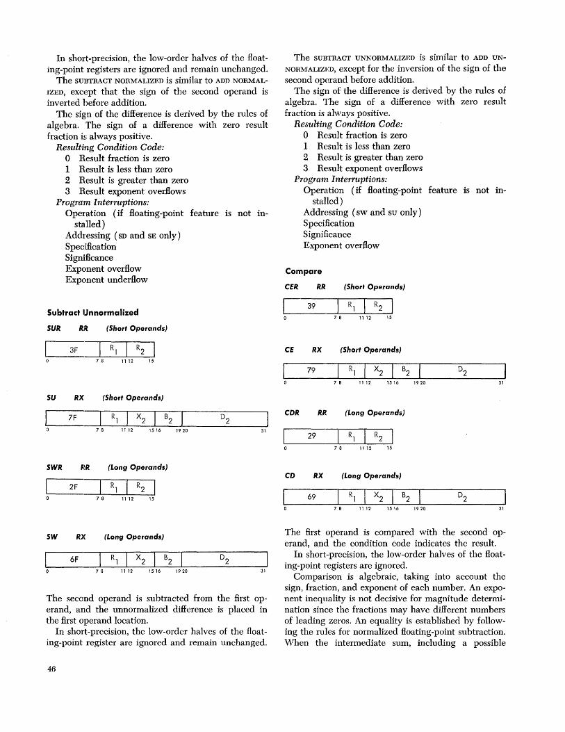
In short-precision, the low-order halves of the Hoating-point registers are ignored and remain unchanged.
The SUBTRACT NORMALIZED is similar to ADD NORMAL
IZED, except that the sign of the second operand is inverted before addition.
The sign of the difference is derived by the rules of algebra. The sign of a difference with zero result fraction is always positive.
Resulting Condition Code: o Result fraction is zero 1 Result is less than zero 2 Result is greater than zero 3 Result exponent overHows
Program Interruptions: Operation (if Hoating-point feature is not in-
stalled) Addressing (SD and SE only) Specification Significance Exponent overHow Exponent underHow
Subtract Unnormalized
SUR RR. (Short Operands)
3F 78 11 12 15
SU RX (Short Operands)
7F
7 8 11 12 1516 1920
SWR (Long Operands)
2F 7 8 11 12 15
SW RX (Long Operands)
6F 7 8 11 12 1516 1920
D2 31
31
The second operand is subtracted from the first operand, and the unnormalized difference is placed in the first operand location.
In short-precision, the low-order halves of the Hoating-point register are ignored and remain unchanged.
46
The SUBTRACT UNNORMALIZED is similar to ADD UN
NORMALIZED, except for the inversion of the sign of the second operand before addition.
The sign of the difference is derived by the rules of algebra. The sign of a difference with zero result fraction is always positive.
Resulting Condition Code: o Result fraction is zero 1 Result is less than zero 2 Result is greater than zero 3 Result exponent overHows
Program Interruptions: Operation (if Hoating-point feature is not in-
stalled) Addressing (sw and su only) Specification Significance Exponent overHow
Compare
CER RR (Short Operands)
39 7 8 11 12 15
CE RX (Short Operands)
I 79 Rl I X2 I B2 0 7 8 11 12 1516 1920
CDR RR (Long Operands)
I 29 Rl I R2 I 0 78 11 12 15
CD RX (Long Operands)
I 69 Rl I X2 I B2 0 7 8 11 12 1516 1920
31
31
The first operand is compared with the second operand, and the condition code indicates the result.
In short-precision, the low-order halves of the Hoating-point registers are ignored.
Comparison is algebraic, taking into account the sign, fraction, and exponent of each number. An exponent inequality is not decisive for magnitude determination since the fractions may have different numbers of leading zeros. An equality is established by following the rules for normalized Hoating-point subtraction. When the intermediate sum, including a possible

guard digit, is zero, the operands are equal. Neither operand is changed as a result of the operation.
Exponent overflow, exponent underflow, or lost significance cannot occur.
Resulting Condition Code: o Operands are equal 1 First operand is low 2 First operand is high 3
Program Interruptions: Operation (if floating-point feature is not in
stalled) Addressing (CD and CE only) Significance
Programming Note
Numbers with zero fraction compare equal even when they differ in sign or characteristic.
Halve
HER RR (Short Operands)
34 7 8 11 12 15
HDR RR (Long Operands)
24 7 8 11 12 15
The second operand is divided by two, and the quotient is placed in the first operand location.
In short-precision, the low-order half of the result register remains unchanged.
The operation shifts the fraction right one bit; the sign and characteristic are not changed. No normalization or test for zero fraction takes place.
Condition Code: The code remains unchanged. Program Interruptions:
Operation (if floating-point feature is not installed)
Specification
Programming Note
The halve operation differs from a divide operation with the number two as divisor in the absence of prenormalization and postnormalization and in the absence of a zero-fraction test.
Multiply
MER RR (Short Operands)
I 3C R] I R2 0 7 8 11 12 15
ME RX (Short Operands)
7C R] I X2 I B2
7 8 11 12 1516 1920 31
MDR RR (Long Operands)
I 2C R] I R2 I 0 7 8 11 12 15
MD RX (Long Operands)
I 6C R] I X2 I B2 0 7 8 11 12 1516 1920 31
The normalized product of multiplier (the second operand) and multiplicand (the first operand) replaces the multiplicand.
The multiplication of two floating-point numbers consists of a characteristic addition and a fraction multiplication. The sum of the characteristics less 64 is used as the characteristic of an intermediate product. The sign of the product is determined by the rules of algebra.
The product fraction is normalized by prenormalizing the operands and postnormalizing the intermediate product, if necessary. The intermediate product characteristic is reduced by the number of left-shifts. For long operands, the intermediate product fraction is truncated before the left-shifting, if any. For short operands (six-digit fractions), the product fraction has the full 14 digits of the long format, and the two loworder fraction digits are accordingly always zero.
Exponent overflow occurs if the final product characteristic exceeds 127. The operation is terminated, and a program interruption occurs. The overflow exception does not occur for an intermediate product characteristic exceeding 127 when the final characteristic is brought within range because of normalization.
Exponent underflow occurs if the final product char-
Floating-Point Arithmetic 47

acteristic is less than zero. The characteristic and fraction are made zero, and a program interruption occurs if the corresponding mask bit is one. Underflow is not signaled when an operand's characteristics become less than zero during prenormalization, and the correct characteristic and fraction value are used in the multiplication.
When all 14 result fraction digits are zero, the product sign and characteristic are made zero, yielding a true zero result without exponent underflow and exponent overflow causing a program interruption. The program interruption for lost significance is never taken for multiplication.
Condit'ion Code: The code remains unchanged. Program Interruptions:
Operation (if floating-point feature is not in-stalled)
Addressing ( MD and ME only) Specification Exponent overflow Exponent underflow
Programming Note
Interchanging the two operands in a floating-point multiplication does not affect the value of the product.
Divide
DER RR. (Short Operands)
30 78 11 12 15
DE RX (Short Operands)
I 70 Rl I X2 I B2
0 7 8 11 12 1516 1920 31
DDR RR (Long Operands)
I 20 Rl I R2 0 78 11 12 15
DD RX (Long Operands)
I 60 Rl I X2 I B2
0 7 8 11 12 1516 1920 31
48
The dividend (the first operand) is divided by the divisor (the second operand) and replaced by the quotient. No remainder is preserved.
In short-precision, the low-order halves of the floating-point register are ignored and remain unchanged.
A floating-point division consists of a characteristic subtraction and a fraction division. The difference between thc dividend and divisor characteristics plus 64 is used as an intermediate quotient characteristic. The sign of the quotient is determined by the rules of algebra.
The quotient fraction is normalized by prenormalizing the operands. Postnormalizing the intermediate quotient is never necessary, but a right-shift may be called for. The intermediate-quotient characteristic is adjusted for the shifts. All dividend fraction digits participate in forming the quotient, even if the normalized dividend fraction is larger than the normalized divisor fraction. The quotient fraction is truncated to the desired number of digits.
A program interruption for exponent overflow occurs when the final-quotient characteristic exceeds 127. The operation is terminated.
A program interruption for exponent underflow occurs if the final-quotient characteristic is less than zero. The characteristic, sign, and fraction are made zero, and the interruption occurs if the corresponding mask bit is one. Underflow is not signaled for the intermediate quotient or for the operand characteristics during prenormalization.
When division by a divisor with zero fraction is attempted, the opcration is suppressed. The dividend remains unchanged, and a program interruption for floating-point divide occurs. When the dividend fraction is zero, the quotient fraction will be zero. The quotient sign and characteristic are made zero, yielding a true zero result without taking the program interruption for exponent underflow and exponent overflow. The program interruption for significance is never taken for division.
Condition Code: The code remains unchanged. Program Interruptions:
Operation (if floating-point feature is not in-stalled)
Addressing (DD and DE only) Specification Exponent overflow Exponent underflow Floating-point divide
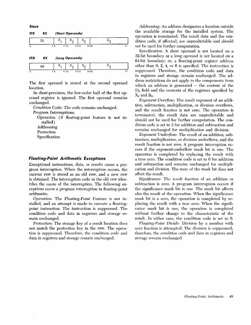
Store
STE RX (Short Operands)
I 70 R, I X
2 I B2
0 7 8 11 12 1516 1920 31
STD RX (Long Operands)
I 60 R, I X
2 I B2
0 7 8 11 12 1516 1920 31
The first operand is stored at the second operand location.
In short-precision, the low-order half of the first operand register is ignored. The first operand remains unchanged.
Condition Code: The code remains unchanged. Program Interruptions:
Operation (if floating-point feature is not in-stalled)
Addressing Protection Specification
Floating-Point Arithmetic Exceptions Exceptional instructions, data, or results cause a program interruption. When the interruption occurs, the current psw is stored as an old psw, and a new psw is obtained. The interruption code in the old psw identifies the cause of the interruption. The following exceptions cause a program interruption in floating-point arithmetic.
Operation: The Floating-Point Feature is not installed, and an attempt is made to execute a floatingpoint instruction. The instruction is suppressed. The condition code and data in registers and storage remain unchanged.
Protection: The storage key of a result location docs not match the protection key in the psw. The operation is suppressed. Therefore, the condition code and data in registers and storage remain unchanged.
Addressing: An address designates a location outside the available storage for the installed system. The operation is terminated. The result data and the condition code, if affected, are unpredictable and should not be used for further computation.
Specification: A short operand is not located on a 32-bit boundary or a long operand is not located on a 64-bit boundary; or, a floating-point register address other than 0, 2, 4, or 6 is specified. The instruction is suppressed. Therefore, the condition code and data in registers and storage remain unchanged. The address restrictions do not apply to the components from which an address is generated - the content of the D2 field and the contents of the registers specified by X2 and B2 •
Exponent Overflow: The result exponent of an addition, subtraction, multiplication, or division overflows, and the result fraction is not zero. The operation is terminated; the result data are unpredictable and should not be used for further computation. The condition code is set to 3 for addition and subtraction and remains unchanged for multiplication and division.
Exponent Underflow: The result of an addition, subtraction, multiplication, or division underflows, and the result fraction is not zero. A program interruption occurs if the exponent-underflow mask bit is one. The operation is completed by replacing the result with a true zero. The condition code is set to ° for addition and subtraction and remains unchanged for multiplication and division. The state of the mask hit does not affect the result.
Significance: The result fraction of an addition or subtraction is zero. A program interruption occurs if the significance mask bit is one. The mask bit affects also the result of the operation. When the significance mask bit is a zero, the operation is completed by replacing the result with a true zero. When the significance mask bit is one, the operation is completed without further change to the characteristic of the result. In either case, the condition code is set to 0.
Floating-Point Divide: Division by a number with zero fraction is attempted. The division is suppressed; therefore, the condition code and data in registers and storage remain unchanged.
Floating-Point Arithmetic 49
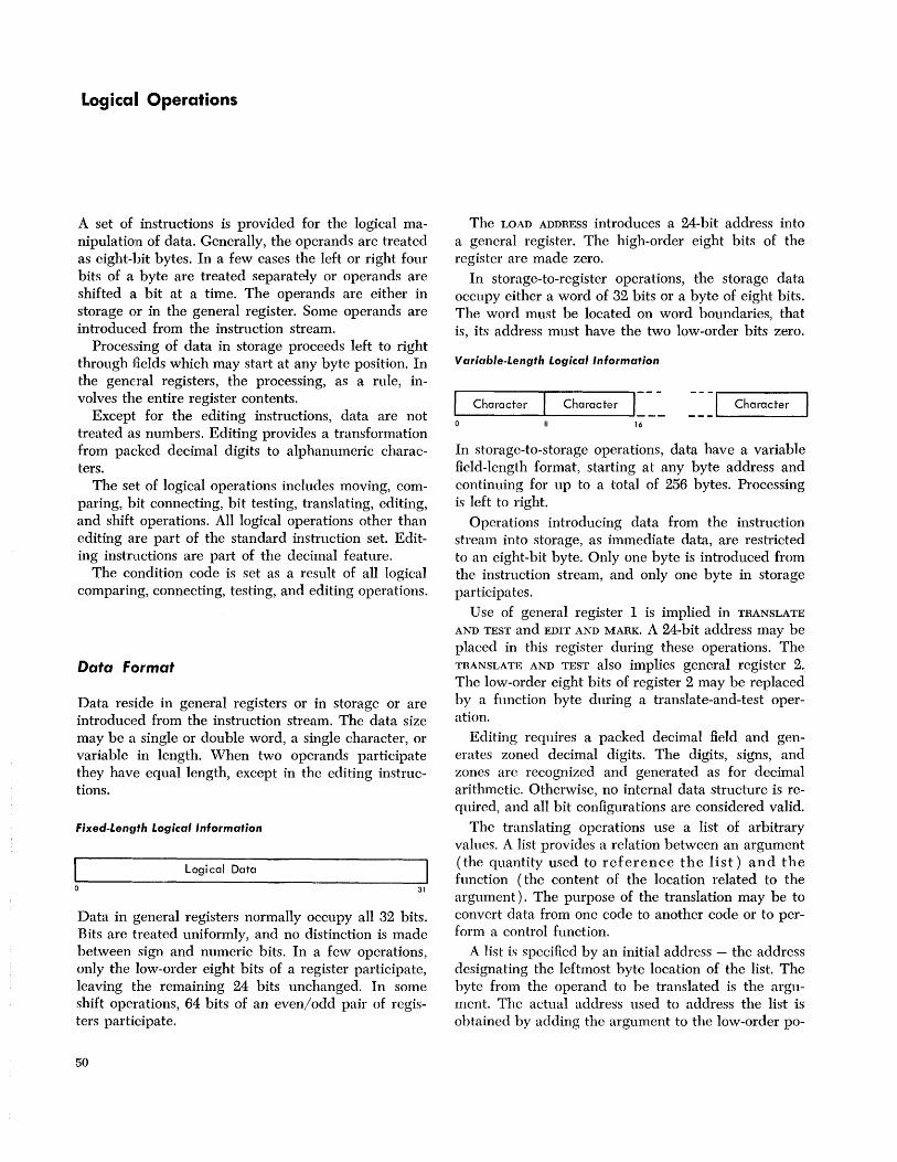
Logical Operations
A set of instructions is provided for the logical manipulation of data. Generally, the operands are treated as eight-bit bytes. In a few cases the left or right four bits of a byte are treated separately or operands are shifted a bit at a time. The operands are either in storage or in the general register. Some operands are introduced from the instruction stream.
Processing of data in storage proceeds left to right through fields which may start at any byte position. In the general registers, the processing, as a rule, involves the entire register contents.
Except: for the editing instructions, data are not treated as numbers. Editing provides a transformation from packed decimal digits to alphanumeric characters.
The set of logical operations includes moving, comparing, bit connecting, bit testing, translating, editing, and shift operations. All logical operations other than editing are part of the standard instruction set. Editing instructions are pali of the decimal feature.
The condition code is set as a result of all logical comparing, connecting, testing, and editing operations.
Data Format
Data reside in general registers or in storage or are introduced from the instruction stream. The data size may be a single or double word, a single character, or variable in length. When two operands participate they have equal length, except in the editing instructions.
Fixed-Lenuth Logical Information
Logical Data
31
Data in general registers normally occupy all 32 bits. Bits are treated uniformly, and no distinction is made between sign and numeric bits. In a few operations, only the low-order eight bits of a register participate, leaving the remaining 24 bits unchanged. In some shift operations, 64 bits of an even/odd pair of registers participate.
50
The LOAD ADDRESS introduces a 24-bit address into a general register. The high-order eight bits of the register are made zero.
In storage-to-register operations, the storage data occupy either a word of 32 bits or a byte of eight bits. The word must be located on word boundaries, that is, its address must have the two low-order bits zero.
Variable-Length Logical Information
Character Character I ~~ ~~] Character
16
In storagc-to-storage operations, data have a variable field-length format, starting at any byte address and continuing for up to a total of 256 bytes. Processing is left to right.
Operations introducing data from the instruction stream into storage, as immediate data, are restricted to an eight-bit byte. Only one byte is introduced from the instruction stream, and only one byte in storage participates.
Use of general register 1 is implied in TRANSLATE
AND TEST and EDIT AND MARK. A 24-bit address may be placed in this register during these operations. The TRANSLATE AND TEST also implies general register 2. The low-order eight bits of register 2 may be replaced by a function byte during a translate-and-test operation.
Editing requires a packed decimal field and generates zoned decimal digits. The digits, signs, and zones are recognized and generated as for decimal arithmetic. Otherwise, no internal data structure is required, and all bit configurations are considered valid.
The translating operations use a list of arbitrary values. A list provides a relation between an argument (the quantity used to reference the list) and the function (the content of the location related to the argument). The purpose of the translation may be to convert data from one code to another code or to perform a control function.
A list is specified by an initial address - the address designating the leftmost byte location of the list. The byte from the operand to be translated is the argument. The actual address used to address the list is obtained by adding the argument to the low-order po-

sitions of the initial address. As a consequence, the list contains 256 eight-bit function bytes. In cases where it is known that not all eight-bit argument values will occur, it may be possible to reduce the size of the list.
In a storage-to-storage operation, the operand fields may be defined in such a way that they overlap. The effect of this overlap depends upon the operation. When the operands remain unchanged, as in COMPARE
or TRANSLATE AND TEST, overlapping does not affect the execution of the operation. In the case of MOVE,
EDIT, and TRANSLATE, one operand is replaced by new data, and the execution of the operation may be affected by the amount of overlap and the manner in which data are fetched or stored. For purposes of evaluating the effect of overlapped operands, consider that data are handled one eight-bit byte at a time. All overlapping fields are considered valid but, in editing, overlapping fields give unpredictable results.
Condition Code The results of most logical operations are used to set the condition code in the psw. The LOAD ADDRESS, IN
SERT CHARACTERS, STORE CHARACTER, TRANSLATE, and the moving and shift operations leave this code unchanged. The condition code can be used for decisionmaking by subsequent branch-on-condition instructions.
The condition code can be set to reHect five types of results for logical operations: For COMPARE LOGICAL
the states 0, 1, or 2 indicate that the first operand is equal, low, or high.
For the logical-connectives, the states ° or 1 indicate a zero or nonzero result field.
For TEST UNDER MASK, the states 0, 1, or 3 indicate that the selected bits are all-zero, mixed zero and one, or all-one,
For TRANSLATE AND TEST, the states 0, 1, or 2 indicate an all-zero function byte, a nonzero function byte with the operand incompletely tested, or a last function byte nonzero.
For editing the states 0, 1, or 2 indicate a zero, less than zero, or greater than zero content of the last result field.
CONDITION CODE SETTING FOR LOGICAL OPEHA TIONS
0 1 2 3 And zero not zero Compare Logical equal low high Edit zero < zero > zero Edit and Mark zero < zero > zero Exclusive Or zero not zero Or zero not zero Test Under Mask zero mixed one Translate and Test zero incomplete complete
Instruction format Logical instructions use the following five formats:
RR Format
I Op Code R1 R2
o 78 1112 15
RX Format
Op Code R1 X2 B2
7 8 11 12 1516 1920 31
R5 Format
Op Code R1 R3 B2
7 8 11 12 1516 1920 31
51 Format
Op Code
7 8 15 16 1920 31
5S Format
Op Code L B1 I ~?D11 B2 IJ3J 78 1516 1 9 20 31 32 35 36 47
In the RR, RX, and RS formats, the content of the register specified by Rl is called the first operand.
In the SI and ss formats, the content of the general register specified by Bl is added to the content of the Dl field to form an address. This address deSignates the leftmost byte of the first operand field. The number of bytes to the right of this first byte is specified by the L field in the ss format. In the SI format the oper~nd size is one byte.
In the RR format, the R2 field specifies the register containing the second operand. The same register may be specified for the first and second operand.
In the RX format, the contents of the general registers specified by the X2 and B2 fields arc added to the content of the D2 field to form the address of the second operand.
In the RS format, used for shift operations, the content of the general register specified by the B2 field is added to the content of the D2 field. This sum is not used as an address but specifies the number of bits of the shift. The RH field is ignored in the shift operations.
Logical Operations 51

In the SI format, the second operand is the eight-bit immediate data field, 12, of the instruction.
In the S8 format, the content of the general register specified by B2 is added to the content of the D2 field to form the address of the second operand. The second operand field has the same length as the first operand field.
A zero in any of the X2, B1, or B2 fields indicates the absence of the corresponding address or shiftamount component. An instruction can specify the same general register both for address modification and for operand location. Address modification is always completed prior to operation execution.
Results replace the first operand, except in STORE
CHARACTER, where the result replaces the second operand. A variable-length result is never stored outside the field specified by the address and length.
The contents of all general registers and storage locations participating in the addressing or execution of an operation generally remain unchanged. Exceptions are the result locations, general register 1 in EDIT AND
MARK, and general registers 1 and 2 in TRANSLATE AND
TEST.
Instructions The logicalinstructions, their mnemonics, formats, and operation codes follow. The table also indicates the feature to which the instruction belongs, when the condition code is set, and the exceptions that cause a program interruption.
NAME MNEMONIC TYPE EXCEPTIONS CODE
Move MVI SI P,A 92 Move MVC SS P,A D2 Move Numerics MVN SS P,A Dl Move Zones MVZ SS P,A D3 Compare Logical CLR RR C 15 Compare Logical CL RX C A,S 55 Compare Logical CLI SI C A 95 Compare Logical CLC SS X,C A D5 AND NR RR C 14 AND N RX C A,S 54 AND NI SI C P,A 94 AND NC SS C P,A D4 OR OR RR C 16 OR 0 RX C A,S 56 OR 01 SI C P,A 96 OR OC SS C P,A D6 Exclusive OR XR RR C 17 Exclusive OR X RX C A,S 57 Exclusive OR XI SI, C P,A 97 Exclusive OR XC SS C P,A D7 Test Under Mask TM SI C A 91 Insert Character IC RX A 43 Store Character STC RX P,A 42 Load Address LA RX 41 Translate TR SS P,A DC Translate and Test TRT SS C A DD Edit ED SS, T,C P,A, D DE F:dit and Mark EDMK SS, T,C P,A, D DF
,52
NAME MNEMONIC TYPE EXCEPTIONS CODE
Shift Left Single Logical SLL RS 89
Shift Right Single Logical SRL RS 88
Shift Left Double Logical SLDL RS, X S 8D
Shift Right Double Logical SRDL RS, X S 8C
NOTES
A Addressing exception C Condition code is set D Data exception P Protection exception S Specification exception T Decimal feature
Programming Note
The fixed-point loading and storing instructions also may be used for logical operations.
Move
MVI 51
92 7 8 1516 1920 31
MVC 55
D2 7 8 1516
The second operand is placed in the first operand location.
The ss format is used for a storage-to-storage move. The SI format introduces one 8-bit byte from the instruction stream.
In storage-to-storage movement the fields may overlap in any desired way. Movement is left to right through each field a byte at a time.
The bytes to be moved are not changed or inspected.
Condition Code: The code remains unchanged. Program Interruptions:
Protection Addressing
Programming Note
It is possible to propagate one character through an entire field by having the first operand field start one character to the right of the second operand field.
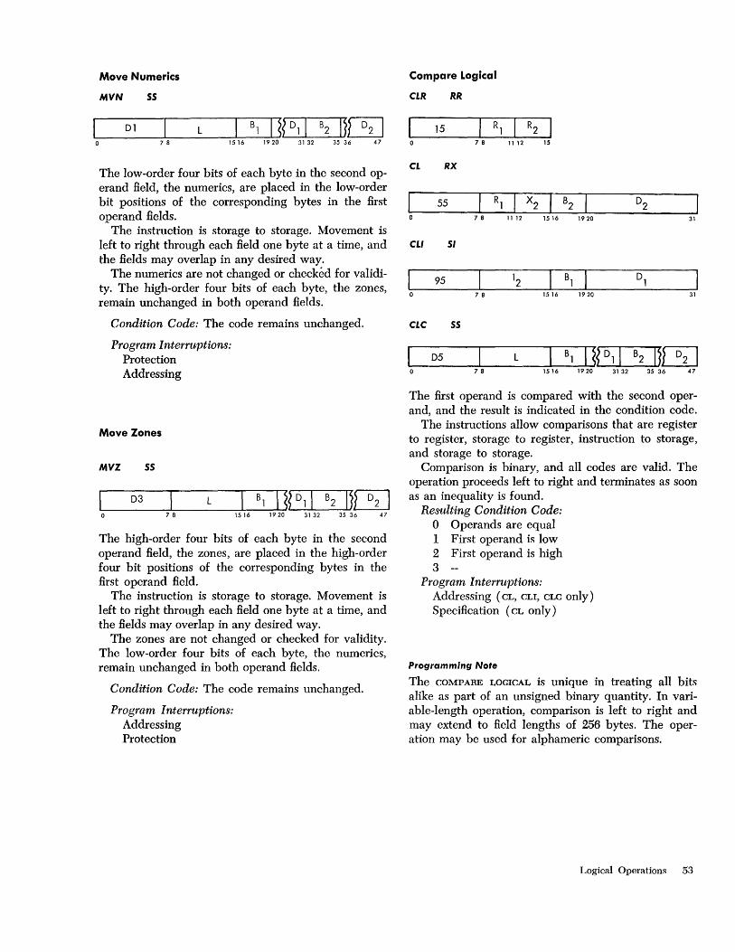
Move Numerics
MVN SS
Dl L 7 8 1516
The low-order four bits of each byte in the second operand field, the numerics, are placed in the low-order bit positions of the corresponding bytes in the first operand fields.
The instruction is storage to storage. Movement is left to right through each field one byte at a time, and the fields may overlap in any desired way.
The numerics are not changed or checked for validity. The high-order four bits of each byte, the zones, remain unchanged in both operand fields.
Condition Code: The code remains unchanged.
Program Interruptions: Protection Addressing
Move Zones
MVZ SS
D3
78
L B1 I ~{D11 B2 11m 1516 19 20 31 32 35 36 47
The high-order four bits of each byte in the second operand field, the zones, are placed in the high-order four bit positions of the corresponding bytes in the first operand field.
The instruction is storage to storage. Movement is left to right through each field one byte at a time, and the fields may overlap in any desired way.
The zones are not changed or checked for validity. The low-order four bits of each byte, the numerics, remain unchanged in both operand fields.
Condition Code: The code remains unchanged.
Program Interruptions: Addressing Protection
Compare Logical
CLR RR
I 15 R1 R2 I 0 78 11 12 15
CL RX
I 55 R1 X2 B2 D2 0 78 11 12 1516 1920 31
CLI SI
95 78 15 16 1920 31
CLC SS
D5 L B1 I ~{D11 B2 11m 78 1516 19 20 31 32 35 36 47
The first operand is compared with the second operand, and the result is indicated in the condition code.
The instructions allow comparisons that are register to register, storage to register, instruction to storage, and storage to storage.
Comparison is binary, and all codes are valid. The operation proceeds left to right and terminates as soon as an inequality is found.
Resulting Condition Code: o Operands are equal 1 First operand is low 2 First operand is high 3
Program Interruptions: Addressing (CL, CLI, CLC only) Specification (CL only)
Programming Note
The COMPARE LOGICAL is unique in treating all bits alike as part of an unsigned binary quantity. In variable-length operation, comparison is left to right and may extend to field lengths of 256 bytes. The operation may be used for alphameric comparisons.
Logical Operations 53
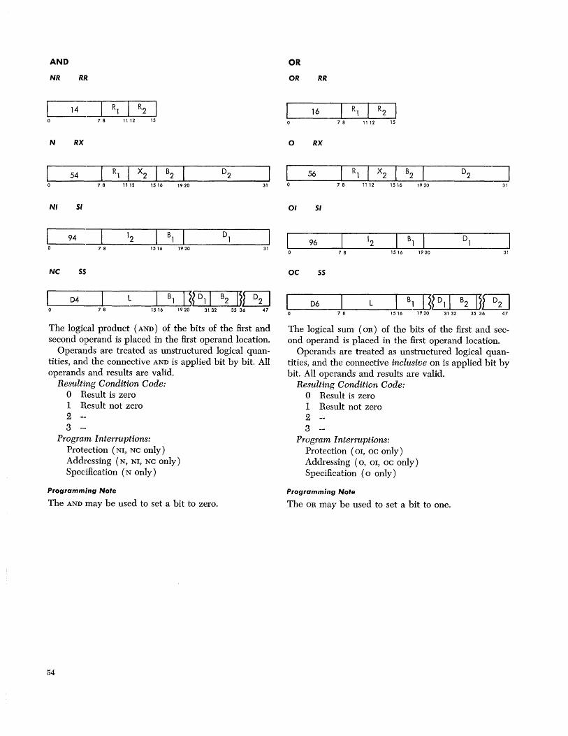
AND
NR RR.
14 78 1112 15
N RX
54 7 8 11 12 15 16 19 20 31
NI 51
94 7 8 1516 1920 31
NC 55
04 L 78 1516
The logical product (AND) of the bits of the first and second operand is placed in the first operand location.
Operands are treated as unstructured logical quantities, and the connective AND is applied bit by bit. All operands and results are valid.
Resulting Condition Code: o Result is zero 1 Result not zero 2 3
Program Interruptions: Protection (NI, NC only) Addressing (N, NI, NC only) Specification (N only)
Programming Note
The AND may be used to set a bit to zero.
54
OR
OR RR
16 78 1112 15
o RX
~1 ___ 5_6 ____ ~ __ Rl~ __ X_2~~B_2~ _______ 0_2 ____ ~ o 7 8 11 12 15 16 19 20 31
01 51
~ ___ 96 ____ ~ ____ 1_2 __ ~~B_1~~ _____ 0_1 ____ ~ 7 8 15 16 19 20 31
OC 55
06 L Bill? 01 I B2 Ijl3J L-------7~8 -----1...J5 "-16-- 1920 31 32 35 36 47
The logical sum (OR) of the bits of the first and second operand is placed in the first operand location.
Operands are treated as unstructured logical quantities, and the connective inclusive OR is applied bit by bit. All operands and results are valid.
Resulting Condition Code: o Result is zero 1 Result not zero 2 3
Program Interruptions: Protection (01, oc only) Addressing (0, 01, oc only) Specification (0 only)
Programming Note
The OR may be used to set a bit to one.
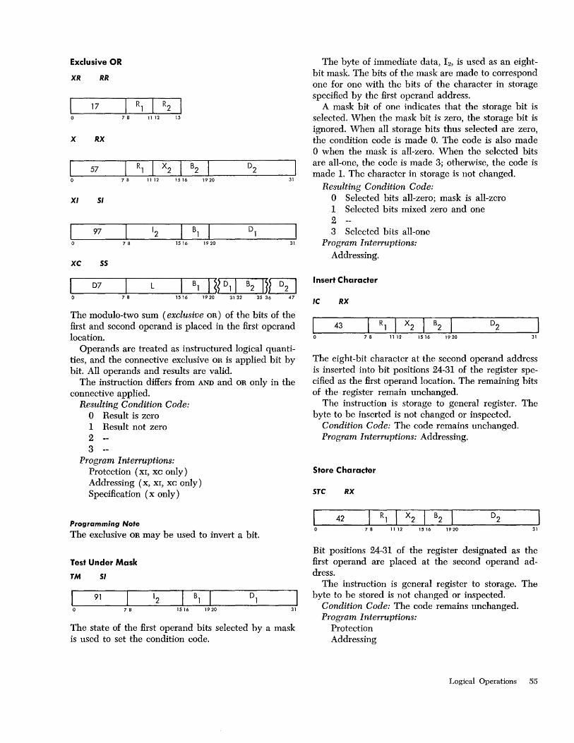
Exclusive OR
XR RR
I 17 R1 R2 0 78 11 12 15
X RX
I 57 R1 X2 B2 D2
0 7 8 11 12 1516 1920 31
XI 51
97 7 8 1516 1920 31
XC 55
D7 L B1 I ~?D11 B2 I~rn 78 1516 1920 31 32 35 36 47
The modulo-two sum (exclusive OR) of the bits of the first and second operand is placed in the first operand location.
Operands are treated as instructured logical quantities, and the connective exclusive OR is applied bit by bit. All operands and results are valid.
The instruction differs from AND and OR only in the connective applied.
Resulting Condition Code: o Result is zero 1 Result not zero 2 3
Program Interruptions: Protection (XI, XC only) Addressing (x, XI, xc only) Specification (x only)
Programming Note
The exclusive OR may be used to invert a bit.
Test Under Mask
TM 51
91
78 1516 1920 31
The state of the first operand bits selected by a mask is used to set the condition code.
The byte of immediate data, 12, is used as an eightbit mask. The bits of the mask are made to correspond one for one with the bits of the character in storage specified by the first operand address.
A mask bit of one indicates that the storage bit is selected. When the mask bit is zero, the storage bit is ignored. When all storage bits thus selected are zero, the condition code is made O. The code is also made o when the mask is all-zero. When the selected bits are all-one, the code is made 3; otherwise, the code is made 1. The character in storage is not changed.
Resulting Condition Code: o Selected bits all-zero; mask is all-zero 1 Selected bits mixed zero and one 2 3 Selected bits all-one
Program Interruptions: Addressing.
Insert Character
IC RX
43 7 8 11 12 15 16 19 20 31
The eight-bit character at the second operand address is inserted into bit positions 24-31 of the register specified as the first operand location. The remaining bits of the register remain unchanged.
The instruction is storage to general register. The byte to be inserted is not changed or inspected.
Condition Code: The code remains unchanged. Program Interruptions: Addressing.
Store Character
5TC RX
42 7 8 11 12 15 16 19 20 31
Bit positions 24-31 of the register designated as the first operand are placed at the second operand address.
The instruction is general register to storage. The byte to be stored is not changed or inspected.
Condition Code: The code remains unchanged. Program Interruptions:
Protection Addressing
Logical Operations 55
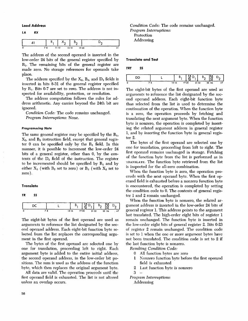
Load Address
LA RX
41 7 8 11 12 15 16 19 20 31
The address of the second operand is inserted in the low-order 24 bits of the general register specified by R i • The remaining bits of the general register are made zero. No storage references for operands take place.
The address specified by the X2, B2, and D2 fields is inserted in bits 8-31 of the general register specified by R i • Bits 0-7 are set to zero. The address is not inspected for availability, protection, or resolution.
The address computation follows the rules for address arithmetic. Any carries beyond the 24th bit are ignored.
Condition Code: The code remains unchanged. Program Interruptions: None.
Programming Note
The same general register may be specified by the Rb X2, and H2 instruction field, except that general register 0 can be specified only by the Ri field. In this manner, it is possible to increment the low-order 24 bits of 2l general register, other than 0, by the contents of the D2 field of the instruction. The register to be incremented should be specified by Ri and by either X2 (with B2 set to zero) or B2 (with X2 set to zero ).
Translah!
TR S5
DC L B1 I ~?Dll B2 IU3J 78 15 16 19 20 31 32 35 36 . 47
The eight-bit bytes of the first operand are used as arguments to reference the list designated by the second operand address. Each eight-bit function byte selected from the list replaces the corresponding argument in the first operand.
The bytes of the first operand are selected one by one for translation, proceeding left to right. Each argument byte is added to the entire initial address, the second operand address, in the low-order bit positions. The sum is used as the address of the function byte, which then replaces the original argument byte.
All data are valid. The operation proceeds until the first operand field is exhausted. The list is not altered unless an overlap occurs.
56
Condition Code: The code remains unchanged. Program Interruptions:
Protection Addressing
Translate and Test
TRT 55
DD 7 8
L B1 I ~{Dll B2 I}~ 1516 1920 3132 3536 47
The eight-bit bytes of the first operand are used as arguments to reference the list designated by the second' operand address. Each eight-bit function byte thus selected from the list is used to determine the continuation of the operation. vVhen the function byte is a zero, the operation proceeds by fetching and translating the next argument byte. When the function byte is nonzero, the operation is completed by inserting the related argument address in general register 1, and by inserting the function byte in general register 2.
The bytes of the first operand are selected one by one for translation, proceeding from left to right. The first operand remains unchanged in storage. Fetching of the function byte from the list is performed as in TRANSLATE. The function byte retrieved from the list is inspected for the all-zero combination.
When the function byte is zero, the operation proceeds with the next operand byte. When the first operand field is exhausted before a nonzero function byte is encountered, the operation is completed by setting the condition code to O. The contents of general register 1 and 2 remain unchanged.
When the function byte is nonzero, the related argument address is inserted in the low-order 24 bits of general register 1. This address points to the argument last translated. The high-order eight bits of register 1 remain unchanged. The function byte is inserted in the low-order eight bits of general register 2. Bits 0-23 of rcgister 2 remain unchanged. The condition code is set to 1 when the one or more argument bytes have not been translated. The condition code is set to 2 if the last function byte is nonzero.
Resulting Condition Code: o All function bytes are zero 1 Nonzero function byte before the first operand
field is exhausted 2 Last function byte is nonzero 3
Program Interruptions: Addressing

Programming Note
The TRANSLATE AND TEST is useful for scanning an input stream and locating delimiters. The stream can thus be rapidly broken into statements or data fields for further processing.
Edit
ED 55
DE L Bl I ~?Dli B2 I~~ 78 1516 19 20 31 32 35 36 47
The format of the source (the second operand) is changed from packed to zoned and is edited under control of the pattern (the first operand). The edited result replaces the pattern.
Editing includes sign and punctuation control and the suppressing and protecting of leading zeros. It also facilitates programmed blanking of all-zero fields. Several numbers may be edited in one operation, and numeric information may be combined with text.
The length field applies to the pattern (the first operand). The pattern has the unpacked format and may contain any character. The source (the second operand) has the packed format and must contain valid decimal digit and sign codes. The left four bits of a byte must be 0000-1001; the codes 1010-1111 are recognized as a data exception and cause a program interruption. The right four bits are recognized as either a sign or a digit.
Both operands are processed left to right one character at a time. Overlapping pattern and source fields give unpredictable results.
The character to be stored in the first operand field is determined by three things: the digit obtained from the source field, the pattern character, and the state of a trigger, called the S trigger. One of three actions may be taken:
1. The source digit is expanded to zoned format and is stored.
2. The pattern character is left unchanged. 3. A fill character is stored. S Trigger: The S trigger is used to control the stor
ing or replacing of source digits and pattern characters. Source digits are replaced when zero suppression or protection is desired. Digits to be stored in the result, whether zero or not, are termed significant. Pattern characters are replaced or stored when they are
significance-dependent (such as punctuation) or signdependent (such as credit symbols). The S trigger also is used to record the sign of the source number and set the condition code accordingly.
The S trigger is set to the zero state at the start of the operation and is subsequently changed depending upon the source number and the pattern characters.
Pattern Character: Three pattern characters have a special use in editing. They are the digit-select character, the significance-start character, and the fieldseparation character. These three characters are replaced, either by a source digit or by a fill character; their encoding is shown in the next table.
1. The digit-select character causes either a source digit or the fill character to be inserted in the result field.
2. The significance-start character has the same function but also indicates, by setting the S trigger, that the foll0'Ying digits are significant.
3. The field-separator character identifies individual fields in a multiple-field editing operation. The character is replaced by the fill character. The S trigger is set to zero, and testing for a zero-field is then reinitiated.
4. All other pattern characters are treated in a common way: If the S trigger is one, the pattern character is left unchanged; if the S trigger is zero, the pattern character is replaced by the fill character.
If the pattern character is either a digit-select or a significance-start character, the source digit is examined. The source digit replaces the pattern character if the S trigger is one or if the source digit is nonzero. If the nonzero digit is inserted when the S trigger is zero, the S trigger is set to one to indicate that the subsequent digits are significant. If the S trigger and the source digit are both zero, the fill character is substituted for the pattern character.
Source Digit: When the source digit is stored in the result, its code is expanded from the packed to the zoned format by attaching a zone. When psw bit 12 is zero, the preferred EBCDIC zone code 1111 is generat,ed. When psw bit 12 is one, the preferred ASCII zone code 0101 is generated.
The source digits are examined only once during an editing operation. They are selected eight bits at a time from the second operand field. The leftmost four bits are examined first, and the rightmost four bits remain available for the next pattern character which calls for a digit examination. However, the rightmost
Logical Operations 57
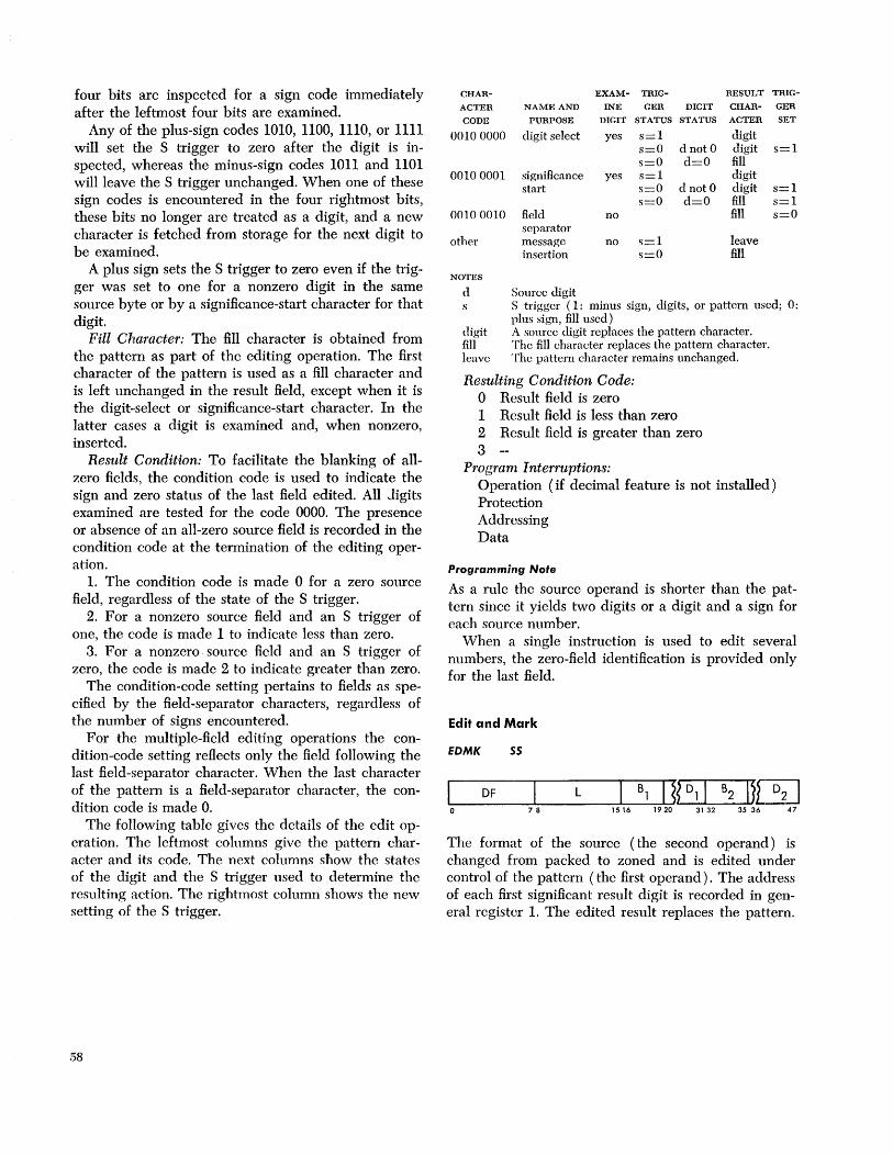
four bits are inspected for a sign code immediately after the leftmost four bits are examined.
Any of the plus-sign codes 1010, 1100, 1110, or 1111 will set the S trigger to zero after the digit is inspected, whereas the minus-sign codes 1011 and 1101 will leave the S trigger unchanged. When one of these sign codes is encountered in the four rightmost bits, these bits no longer are treated as a digit, and a new character is fetched from storage for the next digit to be examined.
A plus sign sets the S trigger to zero even if the trigger was set to one for a nonzero digit in the same source byte or by a significance-start character for that digit.
Fill Character: The fill character is obtained from the pattern as part of the editing operation. The first character of the pattern is used as a fill character and is left unchanged in the result field, except when it is the digit-.select or significance-start character. In the latter cases a digit is examined and, when nonzero, inserted.
Result Condition: To facilitate the blanking of allzero fields, the condition code is used to indicate the sign and zero status of the last field edited. All Jigits examined are tested for the code 0000. The presence or absence of an all-zero source field is recorded in the condition code at the termination of the editing operation.
1. The condition code is made 0 for a zero source field, regardless of the state of the S trigger.
2. For a nonzero source field and an S trigger of one, the code is made 1 to indicate less than zero.
3. For a nonzero source field and an S trigger of zero, the code is made 2 to indicate greater than zero.
The condition-code setting pertains to fields as specified by the field-separator characters, regardless of the number of signs encountered.
For the multiple-field editing operations the condition-code setting reflects only the field following the last field-separator character. When the last character of the pattern is a field-separator character, the condition code is made O.
The following table gives the details of the edit operation. The leftmost columns give the pattern character and its code. The next columns snow the states of the digit and the S trigger used to determine thc resulting action. The rightmost column shows the new setting of the S trigger.
58
CHAR- EXAM- TRIG- RESULT TRIG-
ACTER NAME AND INE GER DIGIT CHAR- GER
CODE PURPOSE DIGIT STATUS STATUS ACTER SET
0010 0000 digit select yes s=l digit s=O dnotO digit s=l s=O d=O fill
00100001 significance yes s=l digit start s=O d nota digit s=l
s=O d=O fill s=l 00100010 field no fill s=O
separator other message no s=l leave
insertion s=O fill
NOTES
d Source digit S trigger (1: minus sign, digits, or pattern used; 0: plus sign, fill used)
digit A source digit replaces the pattern character. fill The fill character replaces the pattern character. leave The pattern character remains unchanged.
Resulting Condition Code: o Result field is zero 1 Result field is less than zero 2 Result field is greater than zero 3
Program Interruptions: Operation (if decimal feature is not installed) Protection Addressing Data
Programming Note
As a rule the source operand is shorter than the pattern since it yields two digits or a digit and a sign for each source number.
When a single instruction is used to edit several numbers, the zero-field identification is provided only for the last field.
Edit and Mark
EDMK 55
DF L B1 I ~?D11 B2 IJ~ 7 8 15 16 19 20 31 32 35 36 47
The format of the source (the second operand) is changed from packed to zoned and is edited under control of the pattern (the first operand). The address of each first significant result digit is recorded in general register 1. The edited result replaces the pattern.
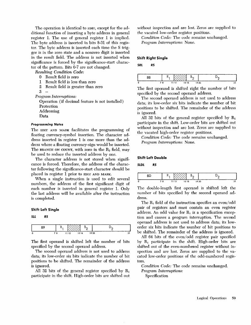
The operation is identical to EDIT, except for the additional function of inserting a byte address in general register 1. The use of general register 1 is implied. The byte address is inserted in bits 8-31 of this register. The byte address is inserted each time the S trigger is in the zero state and a nonzero digit is inserted in the result field. The address is not inserted when significance is forced by the significance-start character of the pattern. Bits 0-7 are not changed.
Resulting Condition Code: o Result field is zero 1 Result field is less than zero 2 Result field is greater than zero 3
Program Interruptions: Operation (if decimal feature is not installed) Protection Addressing Data
Programming Notes
The EDIT AND MARK facilitates the programming of floating currency-symbol insertion. The character address inserted in register 1 is one more than the address where a floating currency-sign would be inserted. The BRANCH ON COUNT, with zero in the R2 field, may be used to reduce the inserted address by one.
The character address is not stored when signiflcance is forced. Therefore, the address of the character following the significance-start character should be placed in register 1 prior to EDIT AND MARK.
When a single instruction is used to edit several numbers, the address of the first significant digit of each number is inserted in general register 1. Only the last address will be available after the instruction is completed.
Shift Left Single
SI.L RS
89 7 8 11 12 1516 1920 31
The first operand is shifted left the number of bits specified by the second operand address.
The second operand address is not used to address data; its low-order six bits indicate the number of bit positions to be shifted. The remainder of the address is ignored.
All 32 bits of the general register specified by Rl participate in the shift. High-order bits are shifted out
without inspection and are lost. Zeros are supplied to the vacated low-order register positions.
Condition Code: The code remains unchanged. Program Interruptions: None.
Shift Right Single
SRL RS
88 7 8 11 12 1516 1920 31
The first operand is shifted right the number of bits specified by the second operand address.
The second operand address is not used to address data; its low-order six bits indicate the number of bit positions to be shifted. The remainder of the address is ignored.
All 32 bits of the general register specified by Rl participate in the shift. Low-order bits are shifted out without inspection and are lost. Zeros are supplied to the vacated high-order register positions.
Condition Code: The code remains unchanged. Program Interruptions: None.
Shift Left Double
SLDL RS
80
7 8 11 12 1516 1920 31
The double-length first operand is shifted left the number of bits specified by the second operand address.
The Rl field of the instruction specifies an even/odd pair of registers and must contain an even register address. An odd value for Rl is a specification exception and causes a program interruption. The second operand address is not used to address data; its loworder six bits indicate the number of bit positions to be shifted. The remainder of the address is ignored.
All 64 bits of the even/odd register pair specified by Rl participate in the shift. High-order bits are shifted out of the even-numbered register without inspection and are lost. Zeros are supplied to the vacated low-order positions of the odd-numbered registers.
Condition Code: The code remains unchanged. Program Interruptions:
Specification
Logical Operations 59
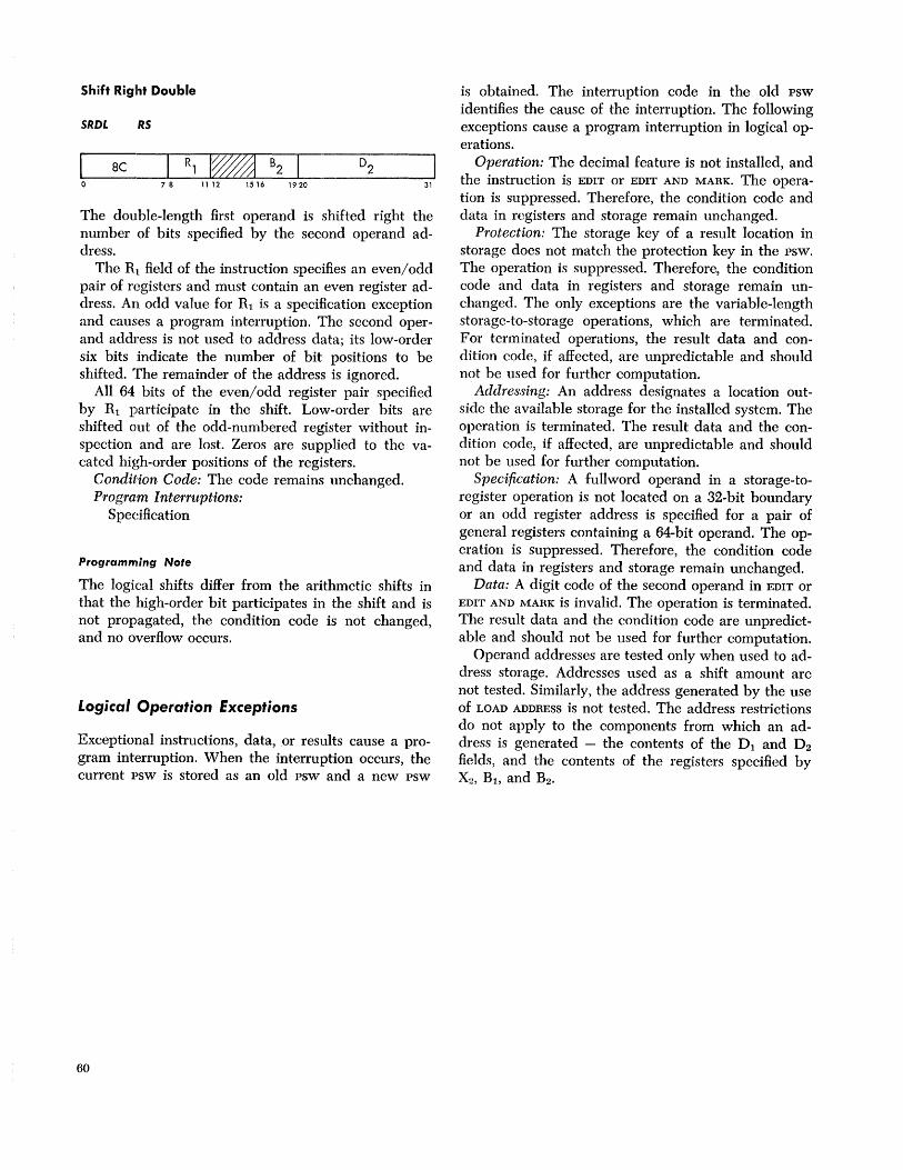
Shift Riglht Double
SRDI. RS
8e 7 8 11 12 1516 1920 31
The double-length first operand is shifted right the number of bits specified by the second operand address.
The R L field of the instruction specifies an even/odd pair of registers and must contain an even register address. An odd value for Rl is a specification exception and causes a program interruption. The second operand address is not used to address data; its low-order six bits indicate the number of bit positions to be shifted. The remainder of the address is ignored.
All 64 bits of the even/odd register pair specified by Rl participate in the shift. Low-order bits are shifted out of the odd-numbered register without inspection and are lost. Zeros are supplied to the vacated high-order positions of the registers.
Condition Code: The code remains unchanged. Program Interruptions:
S pedfica tion
Programming Note
The logical shifts differ from the arithmetic shifts in that the high-order bit participates in the shift and is not propagated, the condition code is not changed, and no overflow occurs.
Logical Operation Exceptions
Exceptional instructions, data,or results cause a program interruption. When the interruption occurs, the current psw is stored as an old psw and a new psw
60
is obtained. The interruption code in the old psw identifies the cause of the interruption. The following exceptions cause a program interruption in logical operations.
Operation: The decimal feature is not installed, and the instruction is EDIT or EDIT AND MARK. The operation is suppressed. Therefore, the condition code and data in registers and storage remain unchanged.
Protection: The storage key of a result location in storage does not match the protection key in the psw. The operation is suppressed. Therefore, the condition code and data in registers and storage remain unchanged. The only exceptions are the variable-length storage-to-storage operations, which are terminated. For terminated operations, the result data and condition code, if affected, are unpredictable and should not be used for further computation.
Addressing: An address designates a location outside the available storage for the installed system. The operation is terminated. The result data and the condition code, if affected, are unpredictable and should not be used for further computation.
Specification: A fullword operand in a storage-toregister operation is not located on a 32-bit boundary or an odd register address is specified for a pair of general registers containing a 64-bit operand. The operation is suppressed. Therefore, the condition code and data in registers and storage remain unchanged.
Data: A digit code of the second operand in EDIT or EDIT AND MARK is invalid. The operation is terminated. The result data and the condition code are unpredictable and should not be used for further computation.
Operand addresses are tested only when used to address storage. Addresses used as a shift amount are not tested. Similarly, the address generated by the use of LOAD ADDRESS is not tested. The address restrictions do not apply to the components from which an address is generated - the contents of the Dl and D2 fields, and the contents of the registers specified by X2 , B1 , and B2 •
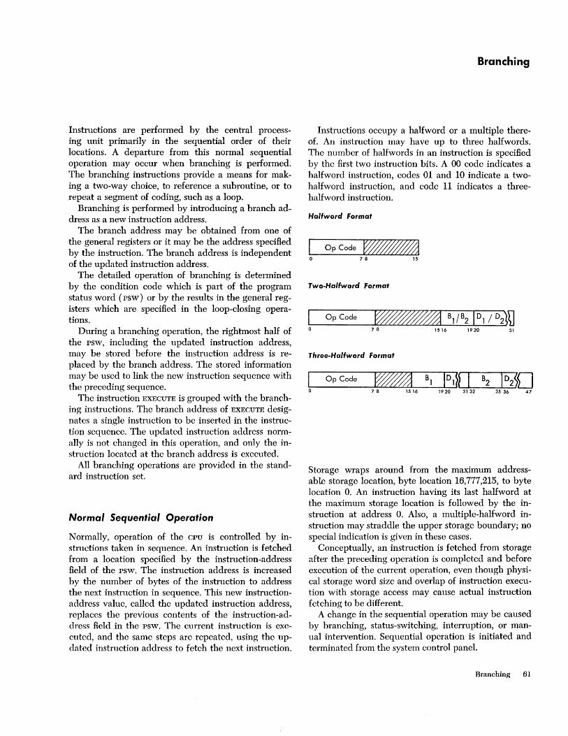
Instructions are performed by the central processing unit primarily in the sequential order of their locations. A departure from this normal sequential operation may occur when branching is performed. The branching instructions provide a means for making a two-way choice, to reference a subroutine, or to ,repeat a segment of coding, such as a loop.
Branching is performed by introducing a branch address as a new instruction address.
The branch address may be obtained from one of the general registers or it may be the address specified by the instruction. The branch address is independent of the updated instruction address.
The detailed operation of branching is determined by the condition code which is part of the program status word (psw) or by the results in the general registers which are specified in the loop-closing operations.
During a branching operation, the rightmost half of the psw, including the updated instruction address, may be stored before the instruction address is replaced by the branch address. The stored information may be used to link the new instruction sequence with the preceding sequence.
The instruction EXECUTE is grouped with the branching instructions. The branch address of EXECUTE designates a single instruction to be inserted in the instruction sequence. The updated instruction address normally is not changed in this operation, and only the instruction located at the branch address is executed.
All branching operations are provided in the standard instruction set.
Normal Sequential Operation
Normally, operation of the CPU is controlled by instructions taken in sequence. An instruction is fetched from a location specified by the instruction-address field of the psw. The instruction address is increased by the number of bytes of the instruction to address the next instruction in sequence. This new instructionaddress value, called the updated instruction address, replaces the previous contents of the instruction-address field in the psw. The current instruction is executed, and the same steps are repeated, using the updated instruction address to fetch the next instruction.
Branching
Instructions occupy a halfword or a multiple thereof. An instruction may have up to three halfwords. The number of halfwords in an instruction is specified by the first two instruction bits. A 00 code indicates a halfword instruction, codes 01 and 10 indicate a twohalfword instruction, and code 11 indicates a threehalfword instruction.
Hallword format
I OpCode ~ o 78 15
Two-Ha/fword format
I Op Code o
Three-Ha/fword format
I Op Code Bl ID1~~ I o 7 8 1516 1920 3132
Storage wraps around from the maximum addressable storage location, byte location 16,777,215, to byte location O. An instruction having its last halfword at the maximum storage location is followed by the instruction at address O. Also, a multiple-halfword instruction may straddle the upper storage boundary; no special indication is given in these cases.
Conceptually, an instruction is fetched from storage after the preceding operation is completed and before execution of the current operation, even though physical storage word size and overlap of instruction execution with storage access may cause actual instruction fetching to be different.
A change in the sequential operation may be caused by branching, status-switching, interruption, or manual intervention. Sequential operation is initiated and terminated from the system control panel.
Branching 61

Programming Note
It is possible to modify an instruction in storage by means of the immediately preceding instructions.
Sequenticd Operation Exceptions
Exceptional instruction addresses or operation codes cause a program interruption. vVhen the interruption occurs, the current psw is stored as an old PSW, and a new psw is obtained. The interruption code in the old psw identifies the cause of the interruption. (In this manual, part of the description of each class of instructions is a list of the program interruptions that may occur for these instructions.) The following program interruptions may occur in normal instruction sequencing, independently of the instruction performed.
Operation: The operation code is not assigned. Addressing: An instruction halfword is located out
side the available storage for the particular installation. Specification: The low-order bit of the instruction
address is one. In each case, the operation is suppressed; therefore,
the condition code and data in storage and registers remain unchanged. The instruction address stored as part of the old psw has been updated by the number of halfwords indicated by the instruction length code in the old psw.
Programming Notes
An unavailable instruction address may occur when normal instruction sequencing proceeds from a valid storage region into an unavailable region or following a branching or status-switching operation.
The oeld instruction address can occur only following branching or status-switching operations.
When the last location in available storage contains an instruction that again introduces a valid instruction address, no program interruption is caused, even though the updated instruction address designates an unavailable location.
The main-storage or register address specification of an instruction with unassigned operation code may cause an addressing or specification interruption when the requirements for the particular instruction class are not met.
Decisiol1l-Making Branching may be conditional or unconditional. Unconditional branches replace the updated instruction address with the branch address. Conditional branches may use the branch address or may leave the updated instruction address unchanged. When branching takes place, the instruction is called successful; otherwise, it is called unsuccessful.
62
Whether a conditional branch is successful depends on the result of operations concurrent with the branch or preceding the branch. The former case is represented by BRANCH ON COUNT and the branch-on-index instructions. The latter case is represented by BRANCH
ON CONDITION, which inspects the condition code that reflects the result of a previous arithmetic, logical, or I/O operation.
The condition code provides a means for data-dependent decision-making. The code is inspected to qualify the execution of the conditional-branch instructions. The code is set by some operations to reHect the result of the operation, independently of the previous setting of the code. The code remains unchanged for all other operations.
The condition code occupies bit positions 34 and 35 of the psw. When the psw is stored during statusswitching, the condition code is preserved as part of the psw. Similarly, the condition code is stored as part of the rightmost half of the psw in a branch-and-link operation. A new condition code is obtained by a LOAD
PSW or SET PROGRAM MASK or by the new psw loaded as a result of an interruption.
The condition code indicates the outcome of some of the arithmetic, logical, or I/O operations. It is not changed for any branching operation, except for EXE
CUTE. In the case of EXECUTE, the condition code is set or left unchanged by the subject instruction, as would have been the case had the subject instruction been in the normal instruction stream.
The table at the end of this section lists all instructions capable of altering the condition code and the meaning of the codes for these instructions.
Instruction Formats Branching instructions use the following three formats:
RR Format
7 8 11 12 15
RX Format
I Op Code I Rl/Mll X2 B2 0 7 8 11 12 1516 1920 31
RS Format
Op Code Rl R3 B2 7 8 11 12 1516 1920 31
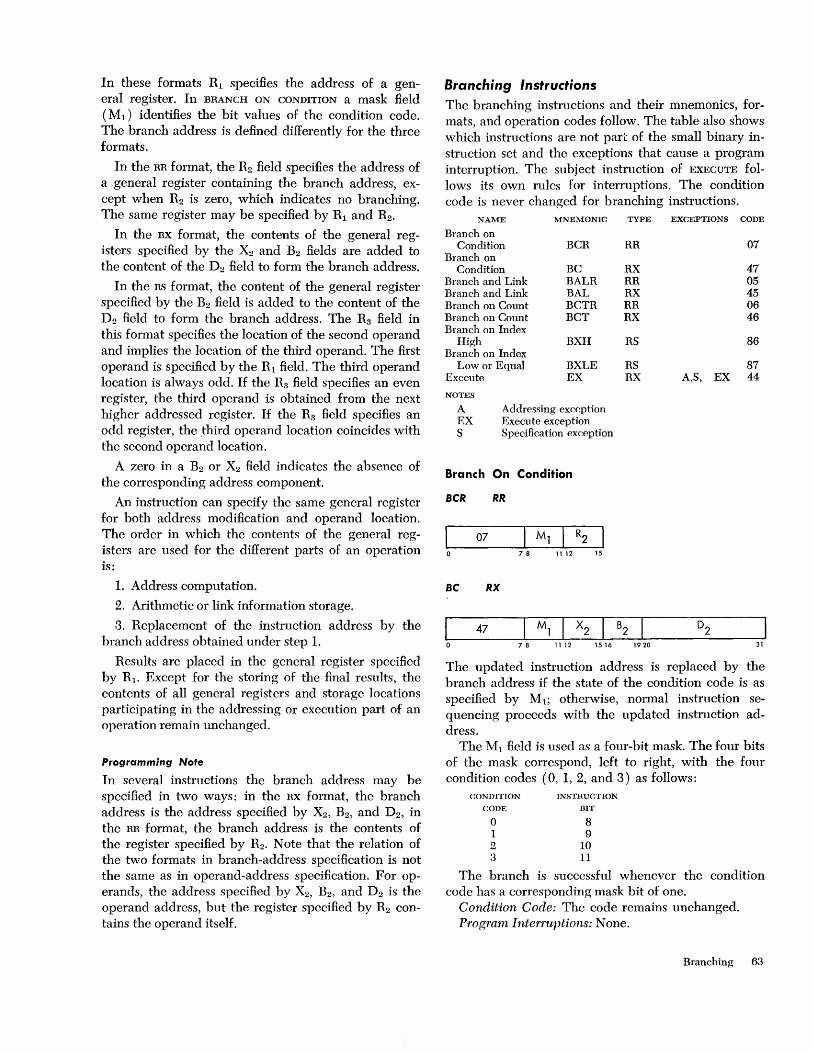
In these formats Rl specifies the address of a general register. In BRANCH ON CONDITION a mask field ( M1 ) identifies the bit values of the condition code. The branch address is defined differently for the three formats.
In the RR format, the R2 field specifies the address of a general register containing the branch address, except when R2 is zero, which indicates no branching. The same register may be specified by Rl and R2.
In the RX format, the contents of the general registers specified by the X2 and B2 fields are added to the content of the D2 field to form the branch address.
In the RS format, the content of the general register specified by the B2 field is added to the content of the D2 field to form the branch address. The Rg field in this format specifies the location of the second operand and implies the location of the third operand. The first operand is specified by the Rl field. The third operand location is always odd. If the Rg field specifies an even register, the third operand is obtained from the next higher addressed register. If the Rg field specifies an odd register, the third operand location coincides with the second operand location.
A zero in a B2 or X2 field indicates the absence of the corresponding address component.
An instruction can specify the same general register for both address modification and operand location. The order in which the contents of the general registers are used for the different parts of an operation is:
1. Address computation.
2. Arithmetic or link information storage.
3. Replacement of the instruction address by the branch address obtained under step 1.
Results are placed in the general register specified by R1 . Except for the storing of the final results, the contents of all general registers and storage locations participating in the addressing or execution part of an operation remain unchanged.
Programming Note
In several instructions the branch address may be specified in two ways: in the RX format, the branch address is the address specified by X2, B2, and D2, in the RR format, the branch address is the contents of the register specified by R2. Note that the relation of the two formats in branch-address specification is not the same as in operand-address specification. For operands, the address specified by X2, B2 , and D2 is the operand address, but the register specified by R2 contains the operand itself.
Branching Instructions The branching instructions and their mnemonics, formats, and operation codes follow. The table also shows which instructions are not part of the small binary instruction set and the exceptions that cause a program interruption. The subject instruction of EXECUTE follows its own rules for interruptions. The condition code is never changed for branching instructions.
NAME
Branch on Condition
Branch on Condition
Branch and Link Branch and Link Branch on Count Branch on Count Branch on Index
High Branch on Index
Low or Equal Execute
NOTES
MNEMONIC TYPE EXCEPTIONS CODE
BCR RR 07
BC RX 47 BALR RR 05 BAL RX 45 BCTR RR 06 BCT RX 46
BXH RS 86
BXLE RS 87 EX RX A,S, EX 44
A Addressing exception EX Execute exception S Specification exception
Branch On Condition
BCR RR
I 07 78 1112 15
BC RX
47 7 8 11 12 15 16 19 20 31
The updated instruction address is replaced by the branch address if the state of the condition code is as specified by M1 ; otherwise, normal instruction sequencing proceeds with the updated instruction address.
The Ml field is used as a four-bit mask. The four bits of the mask correspond, left to right, with the four condition codes (0, 1, 2, and 3) as follows:
CONDITION
CODE
o 1 2 3
INSTRUCTION
BIT
8 9
10 11
The branch is successful whenever the condition code has a corresponding mask bit of one.
Condition Code: The code remains unchanged. Program Interruptions: None.
Branching 63
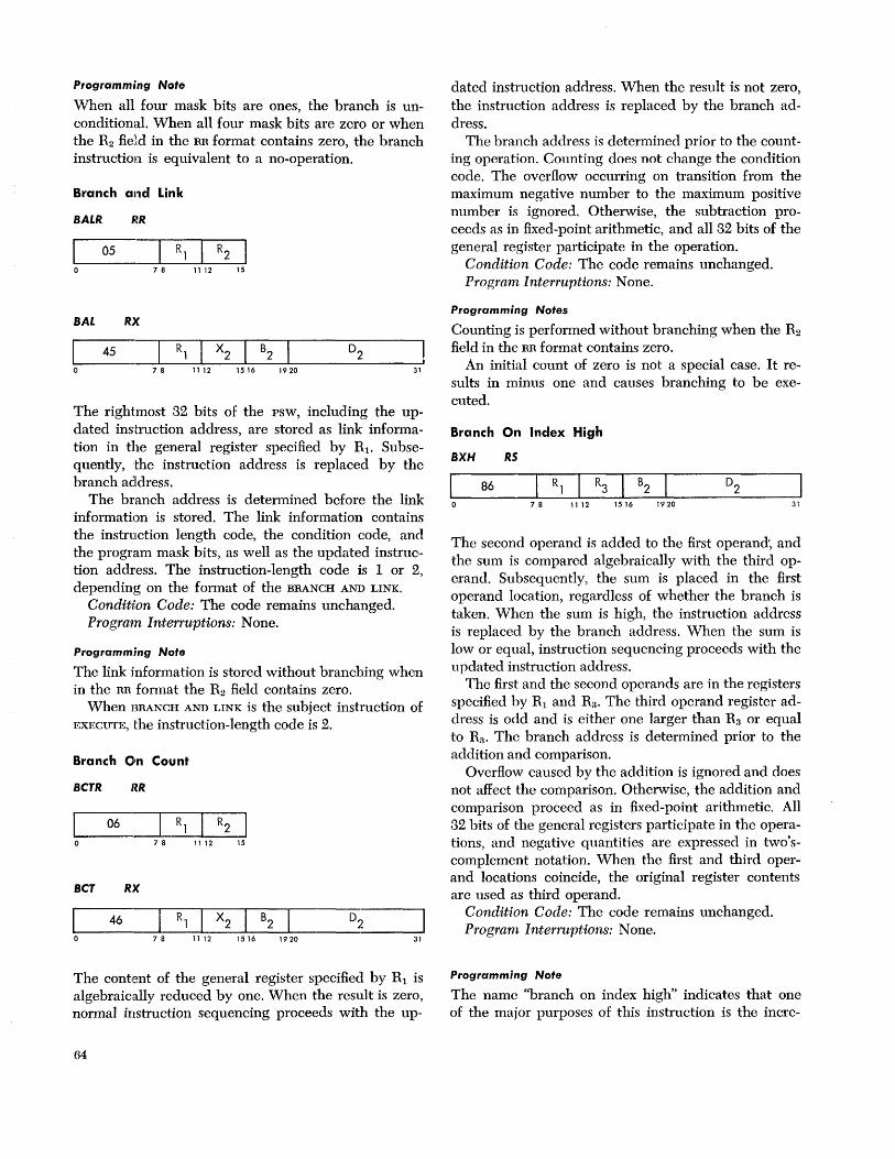
Programming Note
When all four mask bits are ones, the branch is unconditional. When all four mask bits are zero or when the R2 field in the RR format contains zero, the branch instruction is equivalent to a no-operation.
Branch all1d Link
SALR I~R
05 78 1112 15
SAL RX
45 7 8 11 12 15 16 19 20 31
The rightmost 32 bits of the PSW, including the updated instruction address, are stored as link information in the general register specified by RI . Subsequently, the instruction address is replaced by the branch address.
The branch address is determined before the link information is stored. The link information contains the instruction length code, the condition code, and the program mask bits, as well as the updated instruction address. The instruction-length code is 1 or 2, depending on the format of the BRANCH AND LINK.
Condition Code: The code remains unchanged. Program Interruptions: None.
Programm.'ng Note
The link information is stored without branching when in the RR format the R2 field contains zero.
When BRANCH AND LINK is the subject instruction of EXECUTE, the instruction-length code is 2.
Branch On Count
SCTR RR
06 78 1112 15
SCT RX
46 7 8 11 12 15 16 19 20 31
The content of the general register specified by RI is algebraically reduced by one. When the result is zero, normal instruction sequencing proceeds with the up-
64
dated instruction address. When the result is not zero, the instruction address is replaced by the branch address.
The branch address is determined prior to the counting operation. Counting does not change the condition code. The overflow occurring on transition from the maximum negative number to the maximum positive number is ignored. Otherwise, the subtraction proceeds as in fixed-point arithmetic, and all 32 bits of the general register participate in the operation.
Condition Code: The code remains unchanged. Program Interruptions: None.
Programming Notes
Counting is performed without branching when the R2 field in the RR format contains zero.
An initial count of zero is not a special case. It results in minus one and causes branching to be executed.
Branch On Index High
8XH RS
86 7 8 11 12 15 16 19 20 31
The second operand is added to the first operand', and the sum is compared algebraically with the third operand. Subsequently, the sum is placed in the first operand location, regardless of whether the branch is taken. When the sum is high, the instruction address is replaced by the branch address. When the sum is low or equal, instruction sequencing proceeds with the updated instruction address.
The first and the second operands are in the registers specified hy Rl and R3 • The third operand register address is odd and is either one larger than R3 or equal to R.'l' The branch address is determined prior to the addition and comparison.
Overflow caused by the addition is ignored and does not affect the comparison. Otherwise, the addition and comparison proceed as in fixed-point arithmetic. All 32 bits of the general registers participate in the operations, and negative quantities are expressed in two'scomplement notation. When the first and third operand locations coincide, the original register contents are used as third operand.
Condition Code: The code remains unchanged. Program Interruptions: None.
Programming Note
The name "branch on index high" indicates that one of the major purposes of this instruction is the incre-

menting and testing of an index value. The increment may be algebraic and of any magnitude.
Branch On Index Low or Equal
BXLE RS
7 8 11 12 15 16 1 9 20 31
The second operand is added to the first operand, and the sum is compared algebraically with the third operand. Subsequently, the sum is placed in the first operand location, regardless of whether the branch is taken. When the sum is low or equal, the instruction address is replaced by the branch address. When the sum is high, normal instruction sequencing proceeds with the updated instruction address.
The first and the second operands are in the registers specified by Rl and Ri!' The third operand register address is odd and is either one larger than R3 or equal to Ri!. The branch address is determined prior to the addition and comparison.
This instruction is similar to BRANCH ON INDEX HIGH, except that the branch is successful when the sum is low or equal compared to the third operand.
Condition Code: The code remains unchanged. Program Interruptions: None.
Execute
EX RX
44 7 8 11 12 15 16 19 20 31
The single instruction at the branch address is modified by the content of the general register specified by R" and the resulting subject instruction is executed.
Bits 8-15 of the instruction designated by the branch address are oR'ed with bits 24-31 of the register specified by R1 , except when register 0 is specified, which indicates that no modification takes place. The subject instruction may be 16, 32, or 48 bits in length. The oR'ing does not change either the content of the register specified by R] or the instruction in storage and is effective only for the interpretation of the instruction to be executed.
The execution and exception handling of the subject instruction are exactly as if the subject instruction were obtained in normal sequential operation, except for instruction address and instruction-length recording.
The instruction address of the psw is increased by the length of EXECUTE. This updated address and the length code (2) of EXECUTE are stored in the psw in the event of a branch-and-link subject instruction or in the event of an interruption.
When the subject instruction is a successful branching instruction, the updated instruction address of the psw is replaced by the branch address of the subject instruction. When the subject instruction in turn is an EXECUTE, an execute exception occurs and results in a program interruption. The effective address of EXECUTE must be even; if not, a specification exception will cause a program interruption.
Condition Code: The code may be set by the subject instruction.
Program Interruptions: Execute Addressing Specification
Programming Notes
The oR'ing of eight bits from the general register with the designated instruction permits indirect length, index, mask, immediate data, and arithmetic-register specification.
If the subject instruction is a successful branch, the length code still stands at 2.
An addressing or specification exception may be caused by EXECUTE or by the subject instruction.
Branching Exceptions Exceptional instructions cause a program interruption. When the interruption occurs, the current psw is stored as an old psw, and a new psw is obtained. The interruption code in the old psw identifies the cause. Exceptions that cause a program interruption in branching are:
Execute: An EXECUTE instruction has as its subject instruction another EXECUTE.
Addressing: The branch address of EXECUTE designates an instruction-halfword location outside the available storage for the particular installation.
Specification: The branch address of EXECUTE is odd. The last three exceptions occur only for EXECUTE.
The instruction is suppressed. Therefore, the condition code and data in registers and storage remain unchanged.
Exceptions arising for the subject instruction of EXECUTE are the same as would have arisen had the subject instruction been in the normal instruction stream. However, the instruction address stored in the old
Branching 65
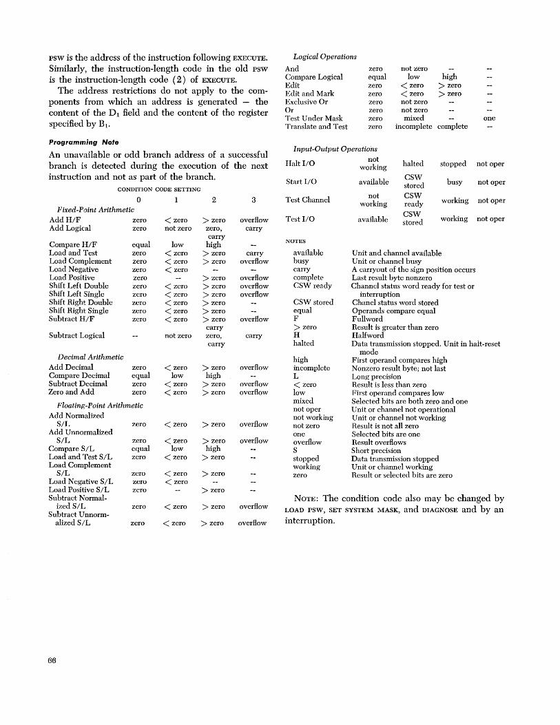
PSW is the address of the instruction following EXECUTE.
Similarly, the instruction-length code in the old psw is the instruction-length code (2) of EXECUTE.
The address restrictions do not apply to the components from which an address is generated - the content of the Dl field and the content of the register specified by B1 •
Programming Note
An unavailable or odd branch address of a successful branch is detected during the execution of the next instruction and not as part of the branch.
CONDITION CODE SETTING
o Fixed-Point Arithmetic
Add H/F zero Add Logical zero
Compare H/F Load and Test Load Complement Load Negative Load Positive Shift Left Double Shift Left Single Shift Right Double Shift Right Single Subtract H/F
Subtract Logical
Decimal Arithmetic Add Decimal Compare Decimal Subtract Decimal Zero and Add
equal zero zero zero zero zero zero zero zero zero
zero equal zero zero
Floating-Point Arithmetic Add Normalized
S/L zero Add Unnormalized
S/L zero Compare S/L equal Load and Test S/L zero Load Complement
S/L zero Load Negative S/L zero Load Positive S/L zero Subtract Normal-
ized S IL zero Subtract Unnorm-
alized S/L zero
66
1
< zero not zero
low < zero < zero < zero
< zero < zero < zero < zero < zero
not zero
< zero low
< zero < zero
< zero
< zero low
< zero
< zero < zero
< zero
< zero
2
> zero zero, carry
high > zero > zero
> zero > zero > zero > zero > zero > zero carry zero, carry
> zero high
> zero > zero
> zero
> zero high
> zero
> zero
> zero
> zero
> zero
3
overflow carry
carry overflow
overflow overflow overflow
overflow
carry
overflow
overflow overflow
overflow
overflow
overflow
overflow
Logical Operations
And zero equal zero zero zero zero zero zero
not zero Compare Logical Edit Edit and Mark Exclusive Or Or Test Under Mask Translate and Test
low < zero < zero not zero not zero mixed
high > zero > zero
incomplete complete one
I nput-Output Operations
Halt I/O
Start I/O
Test Channel
Test I/O
NOTES
available busy carry complete CSW ready
CSW stored equal F > zero H halted
high incomplete L < zero low mixed not oper not working not zero one overflow S stopped working zero
not working
available
not working
available
halted
CSW stored CSW ready
CSW stored
stopped not oper
busy not oper
working not oper
working not oper
Unit and channel available Unit or channel busy A carryout of the sign position occurs Last result byte nonzero Channel status word ready for test or
interruption Chanel status word stored Operands compare equal Fullword Result is greater than zero Halfword Data transmission stopped. Unit in halt-reset
mode First operand compares high Nonzero result byte; not last Long precision Result is less than zero First operand compares low Selected bits are both zero and one Unit or channel not operational Unit or channel not working Result is not all zero Selected bits are one Result overflows Short precision Data transmission stopped U nit or channel working Result or selected bits are zero
NOTE: The condition code also may be changed by LOAD PSW, SET SYSTEM MASK, and DIAGNOSE and by an interrupti on.
A set of operations is provided to switch the status of the CPU, of storage, and of communication between systems.
The over-all CPU status is determined by several program-state alternatives, each of which can be changed independently to its opposite and most of which are indicated by a bit in the program status word (psw). The CPU status is further defined by the instruction address, the condition code, the instructionlength code, the storage-protection key, and the interruption code. These all occupy fields in the psw.
Storage is protected by storage keys, which are matched with a protection key in the psw or in a channel. The protcction status of storage may be changed by introducing new storage keys, using SET STORAGE
KEY. The storage keys may be inspected by using IN
SERT STORAGE KEY.
The system formed by CPU, storage, and I/O can communicate with other systems by means of the signals of the direct control feature and the multisystem feature. The READ DIRECT makes signals available to the CPU; WRITE DIRECT provides signals to other systems.
All status-switching instructions, other than those of the protection feature or direct control feature, are provided in the standard instruction set.
Program States The four types of program-state alternatives, which determine the over-all CPU status, are named Problem/ Supervisor, Wait/Running, Masked/Interruptable, and Stopped/Operating. These states differ in the way they affect the CPU functions and in the way their status is indicated and switched. Each state, except masked, has one alternative.
All program states are independent of each other in their function, indication, and status-switching. Statusswitching does not affect the contents of the arithmetic registers or the execution of I/O operations but may affect the timer operation.
Problem State
The choice between supervisor and problem state determines whether the full set of instructions is valid. The names of these states reflect their normal use.
In the problem state all I/O, protection, and direct-
Status-Switch i ng
control instructions are invalid, as well as LOAD psw, SET SYSTEM MASK, and DIAGNOSE. These are called privileged instructions. A privileged instruction encountered in the problem state constitutes a privileged-operation exception and causes a program interruption. In the supervisor state all instructions are valid.
When bit 15 of the psw is zero, the CPU is in the supervisor state. When bit 15 is one, the CPU is in the problem state. The supervisor state is not indicated on the operator sections of the system control panel.
The CPU is switched between problem and supervisor state by changing bit 15 of the psw. This bit can be changed only by introducing a new psw. Thus status-switching may be performed by LOAD psw, using a new psw with the desired value for bit 15. Since LOAD PSW is a privileged instruction, the CPU must be in the supervisor state prior to the switch. A new psw is also introduced when the CPU is interrupted. The SUPERVISOR CALL causes an interruption and thus may change the CPU state. Similarly, initial program loading introduces a new psw and with it a new CPU state. The new psw may introduce the problem or supervisor state regardless of the preceding state. No explicit operator control is provided for changing the supervisor state.
Timer updating is not affected by the choice between supervisor and problem state.
Programming Note
To allow return from an interruption-handling routine to a preceding program by a LOAD psw, the psw for the interruption routine should specify the supervisor state.
Wait State
In the wait state no instructions are processed, and storage is not addressed repeatedly for this purpose, whereas in the running state, instruction fetching and execution proceed in the normal manner.
When bit 14 of the PSW, is one, the CPU is waiting. When bit 14 is zero, the CPU is in the running state. The wait state is indicated on the operator control section of the system control panel by the wait light.
The CPU is switched between wait and running state by changing bit 14 of the psw. This bit can be changed only by introducing an entire new PSW, as is the case with the problem-state bit. Thus, switching from the
Status Switching 67
running state may be achieved by the privileged instruction LOAD psw, by an interruption such as for SUPERVISOR CALL, or by initial program loading. Switching from the wait state may be achieved by an I/O or external interruption or, again, by initial program loading. The new psw may introduce the wait or running state regardless of the preceding state. No explicit operator control is provided for changing the wait state.
Timer updating is not affected by the choice between running and wait state.
Programming Note
To leave the wait state without manual intervention, the CPU should remain interruptable for some active I/O or external interruption source.
Masked States
The CPU may be masked or interruptable for all systems and machine-check interruptions and for some program interruptions. When the CPU is interruptable for a class of interruptions, these interruptions are accepted. When the CPU is masked, the system interruptions remain pending, while the program and machine-check interruptions are ignored.
The system mask bits (psw bits 0-7), the program mask bits (psw bits 36-39), and the machine-check mask bit (psw bit 13) indicate as a group the masked state of the CPU. When a mask bit is one, the CPU is interruptible for the corresponding interruptions. When the mask bit is zero, these interruptions are masked off. The system mask bits indicate the masked state of the CPU for the multiplexor channel, the six selector channels, and the external signals. The program mask bits indicate the masked state for four of the 15 types of program exceptions. The machinecheck mask bit pertains to all machine checks. Program interruptions not maskable, as well as the supervisor-call interruption, are always taken. The masked states are not indicated on the operator sections of the system control panel.
"Most mask bits do not affect the execution of CPU
operations. The only exception is the significance mask bit, which determines the manner in which a Hoatingpoint operation is completed when a significance exception occurs.
The interruptable state of the CPU is switched by changing the mask bits in the psw. The program mask may be changed separately by SET PROGRAM MASK, and the system mask may be changed separately by the privileged instruction SET SYSTEM MASK. The machinecheck mask bit can be changed only by introducing an entire new PSW, as is the case with the problem-state and wait-state bits. Thus, a change in the entire
68
masked status may be achieved by the privileged instruction LOAD psw, by an interruption such as for supERVISOR CALL, or by initial program loading. The new psw may introduce a new masked state regardless of the preceding state. No explicit operator control is provided for changing the masked state.
Timer updating is not affected by the choice between masked or interruptable states.
Programming Note
To prevent an interruption-handling routine from being interrupted before necessary housekeeping steps are performed, the new psw for that interruption should mask the CPU for further interruptions of the kind that caused the interruption.
Stopped State
When the CPU is in the stopped state, instructions and interruptions are not executed. In the operating state, the CPU executes instructions (if not waiting) and intelTui1tions (if not masked off).
The stopped state is indicated on the operator control section of the system control panel by the manual light. The stopped state is not identified by a bit in the psw.
A change in the stopped or operating state can be effected only by manual intervention or by machine malfunction. No instructions or interruptions can stop or start the CPU. The CPU is commanded to stop when the stop key on the operator intervention section of the system control panel is pressed, when an address comparison indicates equality, and when the rate switch is set to INSTRUCTION STEP. In addition, the CPU
is placed in the stopped state after power is turned on or following a system reset, except during initial program loading. The CPU is placed in the operating state when the start key on the operator intervention panel is pressed. The CPU is also placed in the operating state when initial program loading is commenced.
The transition from operating to stopped state occurs at the end of instruction execution and prior to starting the next instruction execution. When the CPU
is in the wait state, the transition takes place immediately. All interruptions pending and not masked off are taken while the CPU is still in the operating state. They cause an old psw to be stored and a new psw to be fetched before entering the stopped state. Once the CPU is in the stopped state, interruptions are no longer takcn but remain pending.
The timer is not updated in the stopped state.
Programming Notes
Except for timing considerations, execution of a program is not affected by stopping the CPU.

When because of machine malfunction the CPU is unable to end an instruction, the stop key is not effective, and initial program loading or system reset should be used.
Input/output operations continue to completion while the CPU is in the problem, wait, masked, or stopped state. However, no new I/O operations can be initiated while the CPU is stopped, waiting, or in the problem state. Also, the interruption caused by I/O
completion remains pending when masked off or when the CPU is in the stopped state.
Storage Protection Storage protection is provided to protect the contents of certain areas of storage from destruction caused by erroneous storing of information during the execution of a program. This protection is achieved by identifying blocks of storage with a storage key and comparing this key with a protection key supplied with the data to be stored. The detection of a mismatch is a protection exception and results in a program interruption.
Area Identification
For protection purposes, main storage is divided into blocks of 2,048 bytes, each block having an address that is a multiple of 2,048. A four-bit storage key is associated with each block. When data are stored in a storage block, the storage key is compared with the protection key. The protection key of the current psw is used as the comparand when storing is specified by an instruction. When storing is specified by a channel operation, the protection key supplied to the channel by the command address word is used as the comparand. The keys are said to match when they are equal or when either one is zero.
The storage key is not part of addressable storage. The key is changed by SET STORAGE KEY and is inspected by INSERT STORAGE KEY. The protection key in the psw occupies bits 8-11 of that control word. The protcction key of a channel is recorded in bits 0-3 of the channel status word, which is stored as a result of the channel operation.
Protection Action
The storage-protection system is always active. It is independent of the problem, supervisor, or masked state of the CPU and of the type of instruction or I/O
command being executed. When an instruction causes a protection mismatch,
execution of the instruction is suppressed or terminated, and program execution is altered by a program
interruption. The protected storage location always remains unchanged.
In general, the detection of a protected location causes the instruction specifying this location to be suppressed, that is to be omitted entirely. In operations using multiple words or variable-length fields, part of the operation may already have been completed when the protected area is referenced. In these operations the instruction cannot be suppressed and, hence, is terminated.
Protection mismatch due to an I/O operation causes data transmission to be terminated in such a way that the protected storage location remains unchanged. The mismatch is indicated in the channel status word stored as a result of the operation.
Storage protection is optional in some models. When protection is not installed, the protection key in the psw and the protection key of the channels must be zero; otherwise, a program interruption or programcheck I/O termination occurs.
Locations Protected
All main-storage locations where information is stored in the course of an operation are subject to protection. A location not actually used does not cause protection action.
Locations whose addresses are generated by the CPU for updating or interruption purposes, such as the timer, channel status word, or psw addresses, are not protected. However, when the program specifies these locations, they are subject to protection.
Program Status Word The psw contains all information not contained in storage or registers but required for proper program execution. By storing the PSW, the program can preserve the detailed status of the CPU for subsequent inspection. By loading a new psw or part of a PSW, the state of the CPU may be changed.
In certain circumstances all of the psw is . . _ .0d or loaded; in others, only part of it. The entire psw is stored, and a new psw is introduced when the CPU is interrupted. The rightmost 32 bits are stored in BRANCH AND LINK. The LOAD PSW introduces a new PSW; SET PROGRAM mask introduces a new condition code and program-mask field in the psw; SET SYSTEM
MASK introduces a new system-mask field. The psw has the following format:
Program Status Word
System Mask Interrupti on Code
31
Instruction Address
32 33 34 35 36 39 40 63
Status Switching 69

The following is a summary of the purposes of the psw fields:
System Mask: Bits 0-7 of the psw are associated with I/O channels and external signals as specified in the following table. When a mask bit is one, thc source can interrupt the cpu. When a mask bit is zero, the corresponding source can not interrupt the cpu and interruptions remain pending.
SYSTEM
MASK HIT
o 1 2 3 4 5 6 7 7 7
INTERRUPTION SOURCE
Multiplexor channel Selector channel 1 Selector channel 2 Selector channel 3 Selector channel 4 Selector channel 5 Selector channel 6 Timer Interrupt key External signal
Protection Key: Bits 8-11 of the psw form the cpu protection key. The key is matched with a storage key whenever a result is stored. When the protection feature is not implemented, bits 8-11 must be zero when loaded and are zero when stored.
ASCII(A): When bit 12 of the psw is one, the codes preferred for the extended ASCII code are generated for decimal results. When psw 12 is zero, the codes preferred for the extended binary-coded-decimal interchange code are generated.
Machine-Check Mask (M): When psw bit 13 is one, the machine-check interruption, machine check outsignal, and diagnostics occur upon malfunction detection. When bit 13 of the psw is zero, the cpu is masked for machine-check interruptions, and any associated signals and diagnostic procedures do not take place. The interruption does not remain pending.
Wait State (W): ""hen bit 14 of the psw is one, the cpu is in the wait state. When psw bit 14 is zero, the cpu is in the running state.
Problem State (P): When bit 15 of the psw is one, the cpu is in the problem state. When psw bit 15 is zero, the cpu is in the supervisor state.
Interruption Code: Bits 16-31 of the psw identify the cause of an I/O, program, supervisor call, or external interruption. The code is zero when a machinecheck interruption occurs. Use of the code for all five interruption types is shown in a table appearing in the "Interruptions" section.
Instruction Length Code (ILC): The code in psw bits 32 and 33 indicates the length, in halfwords, of the last-interpreted instruction when a program or supervisor-call interruption occurs. The code is unpredictable for I/O, external, or machine-check interruptions. Encoding of these bits is summarized in a table appearing in the "Interruptions" sections.
70
Condition Code (CC): Bits 34 and 35 of the psw are the two bits of the condition code. The condition codes for all instructions arc summarized in a table appearing in the "Branching" section.
Program Mask: Bits 36-39 of the psw are the four program mask bits. Each bit is associated with a program exception, as specified in the following table. When the mask bit is one, the exception results in an interruption. When the mask bit is zero, no interruption occurs. The significance mask bit also detennines the manner in which Hoating-point addition and subtraction are completed.
PROGRAM
MASK BIT PROGHAM EXCEPTION
36 Fixed-point overflow 37 Decimal overflow 38 Exponent underflow 39 Significance
Instruction Address: Bits 40-63 of the psw are the instruction address. This address specifies the leftmost eight-bit byte position of the next instruction.
Multisystem Operation Various fcatures are provided to permit communication between individual systems. Messages may be transmitted by means of a shared I/O device, a channel connector, or a shared storage unit. Signaling may be accomplished when the direct control feature is installed by WRITE DIRECT and READ DIRECI' and by the signal-in lines of the external interruption.
The multisystem feature adds to these facilities the ability to relocate direct addressed locations, to signal the machine malfunction of one system to another, and to initiate system operation from another system.
Direct Address Relocation
Addresses 0-4095 can be generated without a base address or index. This property is important when the psw and general register contents must be preserved and restored during program-switching. These addresses further include all addresses generated by the cpu for fixed locations, such as old PSW, new psw, channel address word, channel status word, and timer.
This set of addresses can be relocated by means of a main prefix to permit more than one cpu to use one uniquely addressed storage. Furthermore, an alternate prefix is provided to permit a change in relocation in case storage malfunction occurs or reconfiguration becomes otherwise desirable.
A prefix is used whenever an address has the highorder 12 bits all-zero. The use of the prefix is independent of the manner in which the address is generated and does not apply to the components, such as the
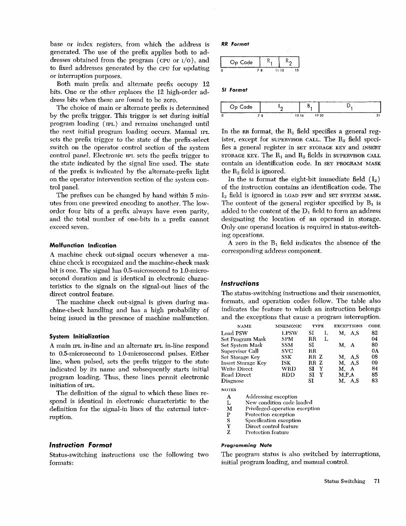
base or index registers, from which the address is generated. The use of the prefix applies both to addresses obtained from the program (CPU or I/O), and to fixed addresses generated by the CPU for updating or interruption purposes.
Both main prefix and alternate prefix occupy 12 bits. One or the other replaces the 12 high-order address bits when these are found to be zero.
The choice of main or alternate prefix is determined by the prefix trigger. This trigger is set during initial program loading (IPL) and remains unchanged until the next initial program loading occurs. Manual IPL
sets the prefix trigger to the state of the prefix-select switch on the operator. control section of the system control panel. Electronic IPL sets the prefix trigger to the state indicated by the signal line used. The state of the prefix is indicated by the alternate-prefix light on the operator intervention section of the system control panel.
The prefixes can be changed by hand within 5 minutes from one prewired encoding to another. The loworder four bits of a prefix always have even parity, and the total number of one-bits in a prefix cannot exceed seven.
Malfunction Indication
A machine check out-signal occurs whenever a machine check is recognized and the machine-check mask bit is one. The signal has D.5-microsecond to l.O-microsecond duration and is identical in electronic characteristics to the signals on the signal-out lines of the direct control feature.
The machine check out-signal is given during machine-check handling and has a high probability of being issued in the presence of machine malfunction.
System Initialization
A main IPL in-line and an alternate IPL in-line respond to O.5-microsecond to 1.0-microsecond pulses. Either line, when pulsed, sets the prefix trigger to the state indicated by its name and subsequently starts initial program loading. Thus, these lines permit electronic initiation of IPL.
The definition of the signal to which these lines respond is identical in electronic characteristic to the definition for the signal-in lines of the external interruption.
Instruction format Status-switching instructions use the following two formats:
RR Format
I Op Code Rl R2 I 0 78 11 12 15
51 Format
Op Code 12 Bl Dl 78 1516 1920 31
In the RR format, the Rl field specifies a general register, except for SUPERVISOR CALL. The R2 field specifies a general register in SET STORAGE KEY and INSERT
STORAGE KEY. The Rl and R2 fields in SUPERVISOR CALL
contain an identification code. In SET PROGRAM MASK
the R2 field is ignored. In the SI format the eight-bit immediate field (12 )
of the instruction contains an identification code. The h field is ignored in LOAD psw and SET SYSTEM MASK.
The content of the general register specified by Bl is added to the content of the Dl field to form an address designating the location of an operand in storage. Only one operand location is required in status-switching operations.
A zero in the Bl field indicates the absence of the corresponding address component.
Instructions
The status-switching instructions and their mnemonics, formats, and operation codes follow. The table also indicates the feature to which an instruction belongs and the exceptions that cause a program interruption.
NAME MNEMONIC TYPE EXCEPTIONS CODE
Load PSW LPSW SI L M, A,S 82 Set Program Mask SPM RR L 04 Set System Mask SSM SI M, A 80 Supervisor Call SVC RR OA Set Storage Key SSK RR Z M, A,S 08 Insert Storage Key ISK RR Z M, A,S 09 Write Direct WRD SI Y M, A 84 Read Direct RDD SI Y M,P,A 85 Diagnose SI M, A,S 83
NOTES
A Addressing exception L New condition codc loaded M Privileged-operation exception P Protection exception S Specification exception Y Direct control feature Z Protection feature
Programming Note
The program status is also switched by interruptions, initial program loading, and manual control.
Status Switching 71

Load PSW
LP5W 51
82 78 1516 1920 31
The double word at the location designated by the operand address replaces the psw.
The operand address must have its three low-order bits zero to designate a double word; otherwise, a specification exception results in a program interruption.
The double word which is loaded becomes the psw for the next sequence of instructions. Bits 40-63 of the double word become the new instruction address. The new instruction address is not checked for available storage or for an even byte address during a load psw operation. These checks occur as part of the execution of the next instructions.
Bits 8-11 of the double word become the new protection key. The protection key must be zero when the protection feature is not installed; otherwise, the key is made zero, and a specification exception causes a program interruption.
The interruption code in bit positions 16-31 of the new psw is not retained as the psw is loaded. When the psw is subsequently stored because of an interruption, these bit positions contain a new code. Similarly, bits 32 and 33 of the psw are not retained upon loading. They will contain the instruction-length code for the last-interpreted instruction when the psw is stored during a branch-and-link operation or during a program or supervisor-call interruption.
Condition Code: The code is set according to bits 34 and 35 of the new psw loaded.
Program Interruptions: Privileged operation Addressing Specification
Programming Note
The CPU enters the problem state when LOAD psw loads a double word with a one in bit position 15 and similarly enters the wait state if bit position 14 is one. The LOAD psw is the only instruction available for entering the problem state or the wait state.
72
Set Program Mask
5PM RR
04 78 11 12 15
Bits 2-7 of the general register specified by the Rl field replace the condition code and the program mask bits of the current psw.
Bits 0, 1, and 8-31 of the register specified by the Rl field are ignored. The contents of the register specified by the R 1 field remain unchanged.
The instruction permits setting of the condition code and the mask bits in either the problem or supervisor state.
Condition Code: The code is set according to bits 2 and 3 of the register specified by R1.
Program Interruptions: None.
Programming Note
Bits 2-7 of the general register may have been loaded from the psw by BRANCH AND LINK.
Set System Mask
5SM 51
80 ~B]I 78 1516 1920 31
The byte at the location designated by the operand address replaces the system mask bits of the current psw.
Condition Code: The code remains unchanged. Program Interruptions:
Privileged operation Addressing
Supervisor Call
SVC RR
I OA R] R2 I o 78 11 12 15
The instruction causes a supervisor-call interruption, with the Rl and R2 field of the instruction providing the intenuption code.

The contents of bit positions 8-15 of the instruction are placed in bit positions 24-31 of the old psw which is stored in the course of the interruption. Bit positions 16-23 of the old psw are made zero. The old psw is stored at location 32, and a new psw is obtained from location 96. The instruction is valid in both problem and supervisor state.
Condition Code: The code remains unchanged in the old psw.
Program Interruptions: None.
Set Storage Key
55K RR
08 7 8 11 12 15
The key of the storage block addressed by the register designated by R2 is set according to the key in the register designated by R1.
The storage block of 2,048 bytes, located on a multiple of the block length, is addressed by bits 8-20 of the register designated by the R2 field. Bits 0-7 and 21-27 of this register are ignored. Bits 28-31 of the register must be zero; otherwise, a specification exception causes a program interruption.
The four-bit storage key is obtained from bits 24-27 of the register designated by the Rl field. Bits 0-23 and 28-31 of this register are ignored.
Condition Code: The code remains unchanged. Program Interruptions:
Operation (if protection feature is not installed) Privileged operation Addressing Specification
Insert Storage Key
15K RR
09 7 8 11 12 15
The key of the storage block addressed by the register designated by R2 is inserted in the register designated by R1 .
The storage block 2,048 bytes, located on a multiple of the block length, is addressed by bits 8-20 of the register designated by the R2 field. Bits 0-7 and
21-27 of this register are ignored. Bits 28-31 of the register must be zero; otherwise, a specification exception causes a program interruption. The four-bit storage key is inserted in bits 24-27 of the register specified by the Rl field. Bits 0-23 of this register remain unchanged, and bits 28-31 are set to zero.
Condition Code: The code remains unchanged. Program Interruptions:
Operation (if protection feature is not installed) Privileged operation Addressing Specification
Write Direct
WRD 51
84 __ L-_B~l-L __ . _____ D_l ______ ] 78 1516 1920 31
The byte at the location designated by the operand address is made available as a set of direct-out static signals. Eight instruction bits are made available as signal-out timing signals.
The eight data bits of the byte fetched from storage are presented on a set of eight direct-out lines as static signals. These signals remain until the next WRITE DIRECT is executed. No parity is presented with the eight data bits.
Instruction bits 8-15, the I2 field, are made available simultaneously on a set of eight signal-out lines as 0.5-microsecond to 1.0-microsecond timing signals. On a ninth line (write out) a 0.5-microsecond to 1.0-microsecond timing signal is made available coincident with these timing signals. The leading edge of the timing signals coincides with the leading edge of the data signals. The eight signal-out lines are also used in READ DIRECT. No parity is made available with the eight instruction bits.
Condition Code: The code remains unchanged. Program Interruptions:
Operation (if direct control feature is not installed) Privileged operation Addressing
Programming Note
The timing signals and the write-out signal may be used to alert the equipment to which the data are sent. When data are sent to another CPU, the external signal interruption may be used to alert that CPU.
Status Switching 73

Read Direct
RDD 51
85 78 15 16 1920 31
Eight instruction bits are made available as signal-out timing signals. A direct-in data byte is accepted from an external device in the absence of a hold signal and is placed in the location designated by the operand address.
Instruction bits 8-15, the 12 field, are made available on a set of eight signal-out lines as O.5-microsecond to l.O-microsecond timing signals. These signal-out lines are also used in WRITE DIRECT. On a ninth line (Read Out) a O.5-microsecond to l.O-microsecond timing signal is made available coincident with these timing signals. The read-out line is distinct from the write-out line in WRITE DIRECT. No parity is made available with the eight instruction bits.
Eight data bits are accepted from a set of eight direct-in Hnes. when the hold signal on the hold-in line is absent. The hold signal is sampled after the read-out signal has been completed and should be absent for at least O.5-microsecond. No parity is accepted with data signals, but a parity bit is generated as the data are placed in storage. When the hold signal is not removed, the CPU does not complete the instruction. Excessive duration of this instruction may result in incomplete updating of the timer.
Condition Code: The code remains unchanged. Program Interruptions:
Operation (if direct control feature is not installed) Privileged operation Protection Addressing
Programming Note
The direct-out lines of one CPU may be connected to the direct-in lines of another CPU, providing cpu-to-cpu static signaling. Further, the write-out signal of the sending CPU may serve as the hold signal for the receiving CPU, temporarily inhibiting a READ DIRECT when the signals are in transition.
Equipment connected to the hold-in line should be so constructed that the hold signal is removed when READ DIRECT is performed. Absence of the hold signal should correspond to absence of current in such a fashion that the CPU can proceed when power is removed from the source of the hold signal.
74
Diagnose
51
83 78 1516 1920 31
The CPU performs built-in diagnostic functions. The purpose of the h field and the operand address
may be defined in greater detail for a particular CPU
and its appropriate diagnostic procedures. Similarly, the number of low-order address bits which must be zero is further specified for a particular CPU. When the address does not have the required number of loworder zeros, a specification exception causes a program interruption.
The purpose of the diagnostic functions is verification of proper functioning of the CPU equipment and locating faulty components.
The DIAGNOSE is completed either by taking the next sequential instruction or by obtaining a new psw from location 112. The diagnostic procedure may affect the problem, supervisor, and interruptable status of the CPU, the condition code, and the contents of storage, registers, and timer, as well as the progress of 1/0
operations. Some diagnostic functions turn on the test light on
the operator control section of the system control panel.
Since the instruction is not intended for problemprogram or supervisor-program use, DIAGNOSE has no mnemonic.
Condition Code: The code is unpredictable. Program Interruptions:
Privileged operation Specification Addressing
Status-Switching Exceptions Exceptional instructions or data cause a program interruption. When the interruption occurs, the current psw is stored as an old PSW, and a new psw is obtained. Thc interruption code inserted in the old psw identifies the cause of the interruption. The following exception conditions cause a program interruption in status-switching operations.
Operation: The direct control feature is not installed, and the instruction is READ DIRECT or WRITE DIRECT; or,

the protection feature is not installed and the instruction is SET STORAGE KEY or INSERT STORAGE KEY.
Privileged Operation: A LOAD PSW, SET SYSTEM MASK,
SET STORAGE KEY, INSERT STORAGE KEY, WRITE DIRECT,
READ DIRECT, or DIAGNOSE is encountered while the processor is in the problem state.
Protection: The storage key of the location designated by READ DIRECT does not match the protection key in the psw.
Addressing: An address designates a location outside the available storage for the installed model.
Specification: The operand address of a LOAD psw does not have all three low-order bits zero; the operand address of DIAGNOSE does not have as many low-order zero bits as required for the particular CPU; the block address specified by SET STORAGE KEY or INSERT
STORAGE KEY does not have the four low-order bits aIIzero; or the protection feature is not installed and a
psw with two nonzero protection keys is introduced. In most of the above interruption conditions, the in
struction is suppressed. Therefore, storage and external signals remain unchanged, and the psw is not changed by information from storage. The only exception is READ DIRECT, which is terminated when a protection or addressing violation is detected. Although storage remains unchanged, a timing signal may have been made available.
When an interruption is taken, the instruction address stored as part of the old psw has been updated by the number of halfwords indicated by the instruction-length code in the old psw.
Operand addresses are tested only when used to address storage. The address restrictions do not apply to the components from which an address is generated: the content of the Dl field and the content of the register specified by B1 .
Status Switching 75

I nterru ptions
The interruption system permits the CPU to change its state as a result of conditions external to the system, in I/O units, or in the CPU itself. The five classes of these conditions are input; output, program, supervisor-call, external, and machine-check interruptions.
Interruption Action An interruption consists of storing the current psw as an old psw and fetching a new psw.
Processing resumes in the state indicated by the new psw. The old psw contains the address of the instruction that would have been executed next if an interruption had not occurred and the instructionlength code of the last-interpreted instruction.
Interruptions are taken only when the CPU is interruptable for the interruption source. Input/output and external interruptions may be masked by the system mask, four of the 15 program interruptions may be masked by the program mask, and the machine-check interruptions may be masked by the machine-check mask.
An interruption always takes place after one instruction interpretation is finished and before a new instruction interpretation is started. However, the occurrence of an interruption may affect the execution of the current instruction. To permit proper programmed action following an interruption, the cause of the interruption is identified and provision is made to locate the last-interpreted instruction.
When the CPU is commanded to stop, the current instruction is finished, and all interruptions that are pending or become pending before the end of the instruction, and which are not masked, are taken.
The details of instruction execution, source identification, and location determination are explained in later sections and are summarized in the following table.
Programming Note
A pending interruption will be taken even if the CPU
becomes interruptable during only one instruction.
76
INSTRUC
TION INTERRUPTION
SOURCE
JDENTlFICA TlON
INTERRUPTION CODE MASK ILC EXE-
PSW BITS 16-31 BITS SET CUTION
Input/Output (old PSW 56, new PSW 120, priority 4)
Multiplcxor channel 00000000 aaaaaaaa 0 x complete Scledor channell 00000001 aaaaaaaa 1 x complcte Scledor channel 2 00000010 aaaaaaaa 2 x complete Selector channel 3 00000011 aaaaaaaa 3 x complete Seledor channel 4 00000100 aaaaaaaa 4 x complete Selector channel 5 00000101 aaaaaaaa 5 x complete Scledor channel 6 00000110 aaaaaaaa 6 x completc
Program (old PSW 40, new PSW 104, priority 2)
Operation 0000000000000001 1,2,3 Privileged opcration 0000000000000010 1,2 Executc 0000000000000011 2 Protcction 0000000000000100 0,2,3
Addressing 00000000 00000101 1,2,3
Specification 00000000 00000110 1,2,3 Data 00000000 00000111 2,3 Fixed-point overflow 00000000 00001000 36 1,2 Fixcd-point divide 00000000 00001001 1,2
Dccimal overflow 00000000 00001010 37 3 Decimal divide 0000000000001011 3 Exponent overflow 00000000 00001100 1,2 Exponcnt underflow 00000000 000011 0 1 38 1,2 Significance 0000000000001110 39 1,2 Floating-point divide 0000000000001111 1,2
supprcss supprcss suppress
suppress/ terminate suppress/ terminate suppress
terminate complete suppress/ complete complete suppress terminate complcte complete suppress
Supel'visol' Call (old PSW 32, new PSW 96, priority 2)
Instruction bits 00000000 r rr r r 1'1' r 1 complete
External (old PSW 24, new PSW 88, priority 3 )
Extcrnal signal 1 00000000 xxxxxxx 1 7 x complete External signal 2 00000000 xxxxxx1x 7 x complete External signal 3 00000000 xxxxx lxx 7 x complete External signal 4 00000000 xxxxlxxx 7 x complete External signal 5 00000000 xxxlxxxx 7 x complete External signal 6 00000000 xxlxxxxx 7 x complete Interrupt key 00000000 xlxxxxxx 7 x complete Timcr 00000000 lxxxxxxx 7 x complete
Machine Check (old PSW 48, new PSW 112, priority 1)
Machine malfunction 00000000 00000000 13 x terminate
NOTES
a Device address bits r Bits of R, and R2 field of SUPERVIson CALL
x Unpredictable
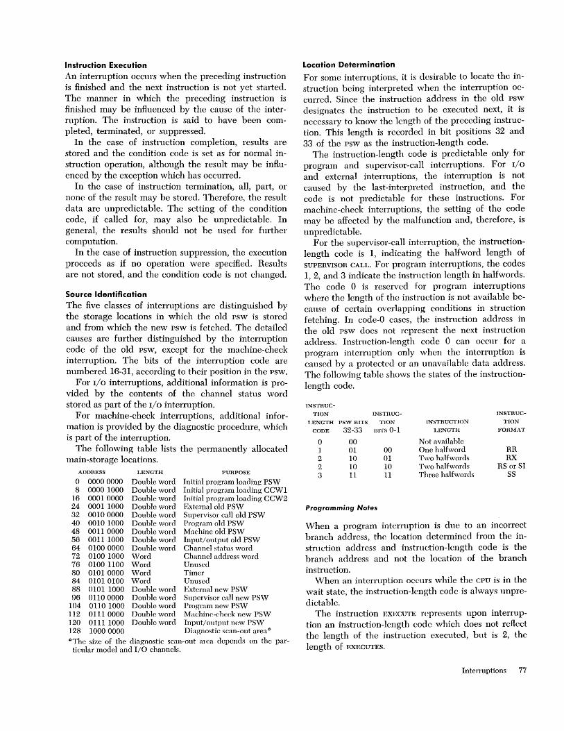
Instruction Execution An interruption occurs when the preceding instruction is finished and the next instruction is not yet started. The manner in which the preceding instruction is finishcd may be influenced by the cause of the interruption. The instruction is said to have been completed, terminated, or suppressed.
In the case of instruction completion, results are stored and the condition code is set as for normal instruction operation, although the result may be influenced by the exception which has occurred.
In the case of instruction termination, all, part, or none of the result may be stored. Therefore, the result data are unpredictable. The setting of the condition code, if called for, may also be unpredictable. In general, the results should not be used for further computation.
In the case of instruction suppression, the execution proceeds as if no operation were specified. Results are not stored, and the condition code is not changed.
Source Identification The five classes of interruptions are distinguished by the storage locations in which the old psw is stored and from which the new psw is fetched. The detailed causes are further distinguishcd by the interruption code of the old psw, except for the machine-check interruption. The bits of the interruption code are numbered 16-31, according to their position in the psw.
For 110 interruptions, additional information is provided by the contents of the channel status word stored as part of the 110 interruption.
For machine-check interruptions, additional information is provided by the diagnostic procedure, which is part of the interruption.
The following table lists the permanently allocated main-storage locations.
ADDRESS LENGTH PURPOSE a 0000 0000 Double word Initial program loading PSW 8 0000 1000 Double word Initial program loading CCW1
16 00010000 Double word Initial program loading CCW2 24 0001 1000 Double word External old PSW 32 0010 0000 Double word Supervisor call old PSW 40 0010 1000 Double word Program old PSW 48 0011 0000 Double word Machine old PSW 56 00111000 Double word Input/output old PSW 64 0100 0000 Double word Channel status word 72 0100 1000 Word Channc1 address word 76 0100 1100 Word Unused 80 0101 0000 Word Timer 84 0101 0100 Word Unused 88 0101 1000 Double word External new PSW 96 0110 0000 Double word Supervisor call new PSW
104 0110 1000 Double word Program new PSW 112 0111 0000 Double word Machine-check new PSW 120 0111 1000 Double word Input/output new PSVV 128 1000 0000 Diagnostic scan-out areal) I)Thc size of the diagnostic scan-out mea depends on the par-
ticular model and I/O channels.
Location Determination
For some interruptions, it is desirable to locate the instruction being interpreted when the interruption occurred. Since the instruction address in the old psw designates the instruction to be executed next, it is necessary to know the lcngth of the preceding instruction. This length is recorded in bit positions 32 and 33 of the psw as the instruction-length code.
The instruction-length code is predictable only for program and supervisor-call interruptions. For I/O
and external interruptions, the interruption is not caused by the last-interpreted instruction, and the code is not predictable for these instructions. For machine-check interruptions, the setting of the code may be affected by the malfunction and, therefore, is unpredictable.
For the supervisor-caB interruption, the instructionlength code is 1, indicating the halfword length of SUPERVISOR CALL. For program interruptions, the codes 1, 2, and 3 indicate the instruction length in halfwords. The code 0 is reserved for program interruptions where the length of the instruction is not available because of certain overlapping conditions in struction fetching. In code-O cases, the instruction address in the old psw does not represent the next instruction address. Instruction-length code 0 can occur for a program interruption only when the interruption is caused by a protected or an unavailable data address. The following table shows the states of the instructionlength code.
INSTRUC-TION INSTRUC- INSTRUC-
J.ENGTH psw BITS TJON INsTRUCTION TION CODE 32-33 BITS 0-1 LENGTH FORMAT
a 00 Not available 1 01 00 One halfword RR 2 10 01 Two halfwords RX 2 10 10 Two halfwords RS or SI 3 11 11 Three halfwords SS
Programming Notes
When a program interruption is due to an incorrect branch address, the location determined from the instruction address and instruction-length code is the branch address and not the location of the branch instruction.
When an interruption occurs while the CPU is in the wait state, the instruction-length code is always unpredictable.
The instruction EXECUTE represents upon interruption an instruction-length code which docs not reflect thc length of the instruction executed, but is 2, the length of EXECUTES.
Interruptions 77
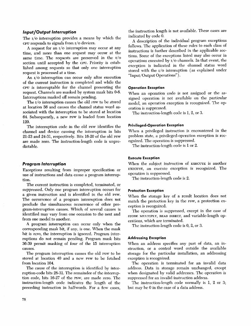
Input/Output Interruption The 1/ () interruption provides a means by which the CPU responds to signals from I/O devices.
A request for an I/O interruption may occur at any time, and more than one request may occur at the same time. The requests are preserved in the I/O
section until accepted by the CPU. Priority is established among requests so that only one interruption request is processed at a time.
An I/O interruption can occur only after execution of the current instruction is completed and while the CPU is interruptable for the channel presenting the request. Channels are masked by system mask bits 0-6. Interruptions masked off remain pending.
The I/O interruption causes the old psw to be stored at location 56 and causes the channel status word associated with the interruption to be stored at location 64. Subsequently, a new psw is loaded from location 120.
The interruption code in the old psw identifies the channel and device causing the interruption in bits 21-23 and 24-31, respectively. Bits 16-20 of the old psw are made zero. The instruction-length code is unpredictable.
Program Interruption Exceptions resulting from improper specification or use of instructions and data cause a program interruption.
The current instruction is completed, terminated, or suppressed. Only one program interruption occurs for a given instruction and is identified in the old psw. The occurrence of a program interruption docs not preclude the simultaneous occurrence of other program-interruption causes. Which of several causes is identified may vary from one occasion to the next and from one model to another.
A program interruption can occur only when the corresponding mask bit, if any, is one. When the mask bit is zero, the interruption is ignored. Program interruptions do not remain pending. Program mask bits 36-39 permit masking of four of the 15 interruption causes.
The program interruption causes the old psw to be stored at location 40 and a new psw to be fetched from location 104.
The cause of the interruption is identified by interruption-code bits 28-31. The remainder of the interruption code, bits 16-27 of the PSW, are made zero. The instruction-length code indicates the length of the preceding instruction in halfwords. For a few cases,
78
the instruction length is not available. These cases are indicated by code O.
A description of the individual program exceptions follows. The application of these rules to each class of instructions is further described in the applicable sections. Some of the exceptions listed may also occur in operations executed by I/O channels. In that event, the exception is indicated in the channel status word stored with the I/O interruption (as explained under "Input/Output Operations").
Operation Exception
When an operation code is not assigned or the assigned operation is not available on the particular model, an operation exception is recognized. The operation is suppressed.
The instruction-length code is 1, 2, or 3.
Privileged-Operation Exception
When a privileged instruction is encountered in the problem state, a privileged-operation exception is recognized. The operation is suppressed.
The instruction-length code is 1 or 2.
Execute Exception
When the subject instruction of EXECUTE is another EXECUTE, an execute exception is recognized. The operation is suppressed.
The instruction-length code is 2.
Protection Exception
When the storage key of a result location does not match the protection key in the PSW, a protection exception is recognized.
The operation is suppressed, except in the case of STORE MULTIPLY, READ DIRECT, and variable-length operations, which are terminated.
The instruction-length code is 0, 2, or 3.
Addressing Exception
When an address specifies any part of data, an instruction, or a control word outside the available storage for the particular installation, an addressing exception is recognized.
The operation is terminated for an invalid data address. Data in storage remain unchanged, except when designated by valid addresses. The operation is suppressed for an invalid instruction address.
The instruction-length code normally is 1, 2 or 3; but may be 0 in the case of a data address.

Specification Exception
A specification exception is recognized when: 1. A data, instruction, or control-word address does
not specify an integral boundary for the unit of information.
2. The Rl field of an instruction specifies an odd register address for a pair of general registers that contains a 64-bit operand.
3. A floating-point register address other than 0, 2, 4, or 6 is specified.
4. The multiplier or divisor in decimal arithmetic exceeds 15 digits and sign.
5. The first operand field is shorter than or equal to the second operand field in decimal multiplication or division.
6. The block address specified in SET STORAGE KEY or INSERT STORAGE KEY has the four low-order bits not all zero.
7. A psw with nonzero protection key is loaded and the protection feature is not installed.
The operation is suppressed. The instruction-length code is 1, 2, or 3.
Data Exception
A data exception is recognized when: 1. The sign or digit codes of operands in decimal
arithmetic or editing operations or in CONVERT TO
BINARY are incorrect. 2. Fields in decimal arithmetic overlap incorrectly. 3. The decimal multiplicand has too many high
order significant digits. The operation is terminated. The instruction-length
code is 2 or 3.
Fixed-Point-Overflow Exception
When a high-order carry occurs or high-order significant bits are lost in fixed-point add, subtract, shift, or sign-control operations, a fixed-point-overflow exception is recognized.
The operation is completed by ignoring the information placed outside the register. The interruption may be masked by psw bit 36.
The instruction-length code is 1 or 2.
Fixed-Point-Divide Exception
A fixed-point-divide exception is recognized when a quotient exceeds the register size in fixed-pOint division, including division by zero, or the result of CON
VERT TO BINARY exceeds 31 bits. Division is suppressed. Conversion is completed by
ignoring the information placed outside the register. The instruction-length code is 1 or 2.
Decimal-Overflow Exception
When the destination field is too small to contain the result field in a decimal operation, a decimal-overflow exception is recognized.
The operation is completed by ignoring the overflow information. The interruption may be masked by psw bit 37.
The instruction-length code is 3.
Decimal-Divide Exception
When a quotient exceeds the specified data field size, a decimal-divide exception is recognized. The operation is suppressed.
The instruction-length code is 3.
Exponent-Overflow Exception
When the result characteristic exceeds 127 in floatingpoint addition, subtraction, multiplication, or division, an exponent-overflow exception is recognized. The operation is terminated.
The instruction-length code is 1 or 2.
Exponent-U nderflow Exception
When the result characteristic is less than zero in floating-point addition, subtraction, multiplication, or division, an exponent-underflow exception is recognized.
The operation is completed by making the result a true zero. The interruption may be masked by psw bit 38.
The instruction-length code is 1 or 2.
Significance Exception
When the result of a floating-point addition or subtraction has an all-zero fraction, a significance exception is recognized.
The operation is completed. The interruption may be masked by psw bit 39. The manner in which the operation is completed is determined by the mask bit.
The instruction-length code is 1 or 2.
Floating-Point-Divide Exception
When division by a floating-point number with zero fraction is attempted, a floating-point divide exception is recognized. The operation is suppressed.
The instruction-length code is 1 or 2.
Supervisor-Col/Interruption The supervisor-call interruption occurs as a result of the execution of SUPEHVISOR CALL.
The supervisor-call interruption causes the old psw to be stored at location 32 and a new psw to be fetched from location 96.
Interruptions 79
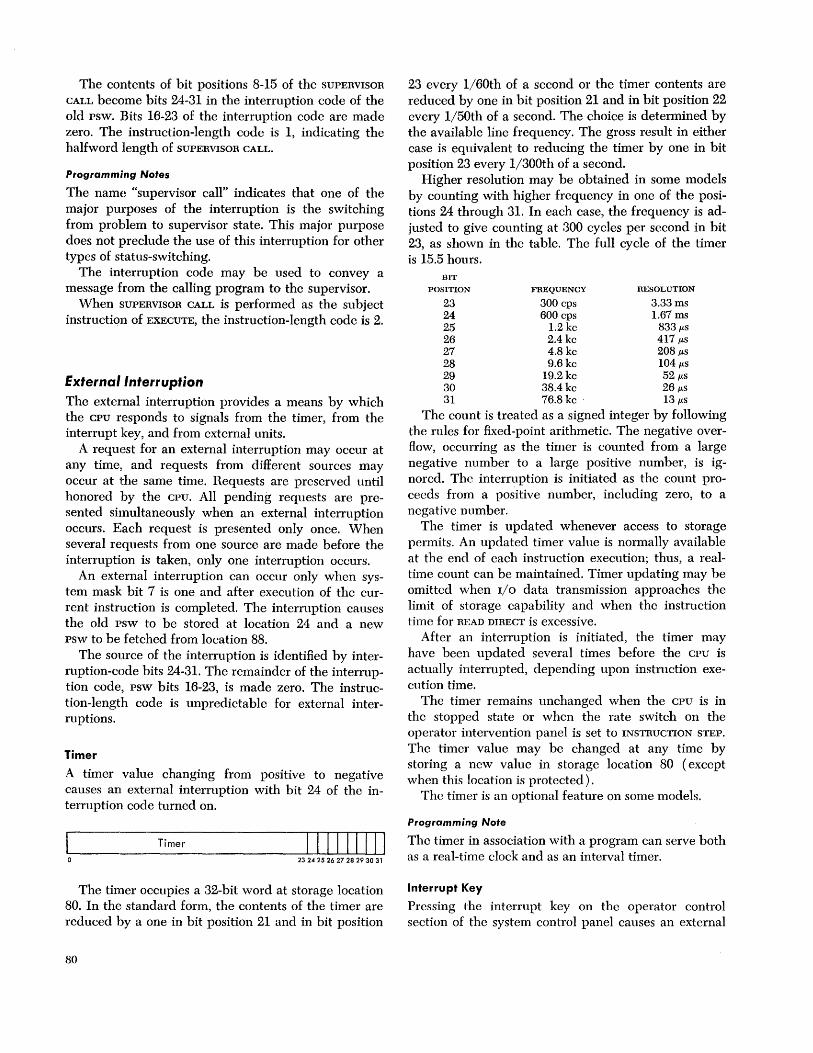
The contents of bit positions 8-15 of the SUPERVISOR
CALL become bits 24-31 in the interruption code of the old psw. Bits 16-23 of the interruption code are made zero. The instruction-length code is 1, indicating the halfword length of SUPERVISOR CALL.
Programming Notes
The name "supervisor call" indicates that one of the major purposes of the interruption is the switching from problem to supervisor state. This major purpose does not preclude the use of this interruption for other types of status-switching.
The jnterruption code may be used to convey a message from the calling program to the supervisor.
When SUPERVISOR CALL is performed as the subject instruction of EXECUTE, the instruction-length code is 2.
External Interruption
The external interruption provides a means by which the CPU responds to signals from the timer, from the interrupt key, and from external units.
A request for an external interruption may occur at any time, and requests from diHerent sources may occur at the same time. Requests are preserved until honored by the CPU. All pending requests are presented simultaneously when an external interruption occurs. Each request is presented only once. When several requests from one source are made before the interruption is taken, only one interruption occurs.
An external interruption can occur only when system mask bit 7 is one and after execution of the current instruction is completed. The interruption causes the old psw to be stored at location 24 and a new psw to be fetched from location 88.
The source of the interruption is identified by interruption-code bits 24-31. The remainder of the interruption code, psw bits 16-23, is made zero. The instruction-length code is unpredictable for external interruptions.
Timer
A timer value changing from positive to negative causes an external interruption with bit 24 of the interruption code turned on.
Timer 111111111 23 24 25 26 27 28 29 30 31
The timer occupies a 32-bit word at storage location 80. In the standard form, the contents of the timer are reduced by a one in bit position 21 and in bit position
80
23 every 1/60th of a second or the timer contents are reduced by one in bit position 21 and in bit position 22 every 1/50th of a second. The choice is determined by the available line frequency. The gross result in either case is equivalent to reducing the timer by one in bit position 23 every 1/300th of a second.
Higher resolution may be obtained in some models by counting with higher frequency in one of the positions 24 through 31. In each case, the frequency is adjusted to give counting at 300 cycles per second in bit 23, as shown in the table. The full cycle of the timer is 15.5 hours.
BIT
POSITION FREQUENCY RESOLUTION
23 300 cps 3.33 ms 24 600 cps 1.67 ms 25 1.2 kc 833 fLS
26 2.4 kc 417 fLS
27 4.8 kc 208 fLS
28 9.6 kc 104 fLS
29 19.2 kc 52 fLS
30 38.4 kc 26 fLS
31 76.8 kc . 13 fLS
The count is treated as a signed integer by following the rules for fixed-pOint arithmetic. The negative overflow, occurring as the timer is counted from a large negative number to a large positive number, is ignored. The interruption is initiated as the count proceeds from a positive number, including zero, to a negative number.
The timer is updated whenever access to storage permits. An updated timer value is normally available at the end of each instruction execution; thus, a realtime count can be maintained. Timer updating may he omitted when I/O data transmission approaches the limit of storage capability and when the instruction time for READ DIRECT is excessive.
After an interruption is initiated, the timer may have been updated several times before the CPU is actually interrupted, depending upon instruction execution time.
The timer remains unchanged when the CPU is in the stopped state or when the rate switch on the operator intervention panel is set to INSTRUCTION STEP.
The timer value may be changed at any time by storing a new value in storage location 80 (except when this location is protected).
The timer is an optional feature on some models.
Programming Note
The timer in association with a program can serve both as a real-time clock and as an interval timer.
Interrupt Key
Pressing the interrupt key on the operator control section of the system control panel causes an external

interruption with bit 25 of the interruption code turned on.
The key is active while power is on.
External Signal
An external signal causes an external interruption, with the corresponding bit in the interruption code turned on.
A total of six signal-in lines may be connected to the CPU for receiving external signals. The pattern presented in interruption-code bits 26-31 depends upon the pattern received before the interruption is taken.
The external signals are part of the direct control feature.
Programming Note
The signal-in lines of one CPU may be connected to the signal-out timing lines of the direct control feature or the machine check out-line of the multisystem feature of another CPU. An interconnection of this kind allows one CPU to interrupt another. Also, the direct-out lines of one CPU may be connected to the direct-in lincs of the other, and vice versa.
Machine-Check Interruption
The machine-check interruption provides a means for recovery from and fault location of machine malfunction.
When the machine-check mask bit is one, occurrence of a machine check terminates the current instruction, initiates a diagnostic procedure, issues a signal on the machine check out-line, and subsequently causes the machine-check interruption.
The old psw is stored at location 48 with an interruption code of zero. The state of the CPU is scanned out into the storage area, starting with location 128 and extending through as many words as the given CPU requires. The new psw is fetched from location 112. Proper execution of these steps depends on the nature of the machine check.
The machine check out-signal is provided as part of the multisystem feature. The signal is a O.5-microsecond to l.O-mierosecond timing signal that follows the I/O interface line-driving and terminating specifications. The signal is designed so that it has a high probability of being issued in the presence of machine malfunction.
When the machine-check mask bit is zero, an attempt is made to complete the current instruction upon the occurrence of a machine check and to proceed with the next sequential instruction. No diagnostic procedure, signal, or interruption occurs.
A change in the machine-check mask bit due to the loading of a new psw results in a change in the treatment of machine checks. Depending on the nature of a machine check, the earlier treatment may still be in force for several cycles.
Following emergency power turn-off and turn-on or system reset, incorrect parity may exist in storage or registers. Unless new information is loaded, a machine check may occur erroneously. Once storage and registers are cleared, a machine check can be caused only by machine malfunction and never by data or instructions.
Machine checks occurring in operations executed by I/O channels either cause a machine-check interruption or are recorded in the channel status word for that operation.
Priority of Interruptions During execution of an instruction, several interruption-causing events may occur simultaneously. The instruction may give rise to a program interruption, an external interruption may occur, a machine check may occur, and an I/O interruption request may be made. Instead of the program interruption, a supervisor-call i~terruption might occur; however, both cannot occur since these two interruptions are mutually exclusive. Simu1taneous interruption requests are honored in a predetermined order.
The machine-check interruption has highest priority. When it occurs, the current operation is terminated. Program and supervisor-call interruptions that would have occurred as a result of the current instruction are eliminated. Every reasonable attempt is made to limit the side-effects of a machine check. Normally, I/O and external interruptions, as well as the progress of the I/O data transfer and the updating of the timer, remain unaffected.
When no machine check occurs, the program interruption or supervisor-call interruption is taken first, the external interruption is taken next, and the I/O interruption is taken last. The action consists of storing the old psw and fetching the new psw belonging to the interruption first taken. This new psw is subsequently stored without any instruction execution, and the next interruption psw is fetched. This storing and fetching continues until no more interruptions are to be serviced. The external and I/O interruptions are taken only if the immediately preceding psw indicates that the CPU is interruptable for these causes.
Instruction execution is resumed using the lastfetched psw. The order of executing interruption subroutines is therefore the reverse of the order in which the psw's arc fetched.
Interruptions 81
The interruption code of a new psw is not loaded since a new interruption code is always storcd. The instruction-length code in a new psw is similarly ignored since it is unpredictable for all interruptions other than program or supcrvisor call. The protcction key of a new psw is stored unchanged when the protection feature is installed. When the feature is not installed, the protection key is made zero upon storing.
Programming Note
When interruption sources are not masked off, thc order of priority in handling the intcrruption subroutines is machine check, I/O, external, and program or supervisor call. This order can be changed to some extent by masking. The priority rule applies to interruption requests made simultaneously. An interruption request made after some interruptions have already been taken is honored according to the priority prevailing at the moment of request.
Interruption Exceptions The only exception that can cause a program interruption during an interruption is a specification exception.
Specification: The protection feature is not installed, and a new psw with nonzero protection kcy is loaded.
A program interruption is taken immediately upon
82
loading thc new PSW, regardless of the type of interruption introducing thc erroneous protection key and prior to any other pending interruptions. The protection key is made zero when the psw is stored.
If the new psw for the program interruption has a nonzero protection key, another program interruption occurs. Since this second program interruption introduces the same unacceptable protection key in the new PSW, the process is repeated with the CPU caught in a string of program interruptions. This string can be broken only by initial program loading or system reset.
The instruction address in a new psw is not tested for availability or resolution as the psw is fetched during an interruption. However, an unavailable or odd instruction address is detected as soon as the instruction address is used to fetch an instruction. These exceptions are described in the section on normal sequential operation.
If the new psw for the program interruption has an unacceptable instruction address, another program interruption occurs. Since this second program interruption introduces the same unaccept'able instruction address, a string of program interruptions is established. This string may be broken by an external or I/O interruption. If these interruptions also have an unacceptable new psw, new supervisor information must be introduced by initial program loading or by manual intervention.

Transfer of information to and from main storage, other than to or from the central processing unit or via the direct control path, is referred to as input and output operation. An inputloutput (1/0) operation involves the use of an inputloutput device. Input! output devices perform 110 operations under control of control units, which are attached to the central processing unit (cpu) by means of channels.
This portion of the manual describes, from the programming point of view, the control of 110 devices by the channels and the CPU. The programmed control procedures apply to all 1/0 operations and are independent of the type of 110 device, its speed, or its mode of op·eration.
Attachment of Input/Output Devices
Input / Output Devices
Input! output devices provide external storage and a means of communication between data processing systems or between a system and the external world. Input! output devices include such equipment as card read-punches, magnetic tape units, direct-access-storage devices (disk or drum), typewriter-keyboard devices, printers, TELE-PROCESSING devices, and process control equipment.
Most types of 110 devices, such as printers, card equipment, or tape devices, deal directly with external documents, and these devices are physically distinguishable and identifiable. Other types consist only of electronic equipment and do not directly handle physical recording media. The channel-to-channel adapter, for example, provides a channel-to-channel data transfer path, and the data never reach a physical recording medium outside main storage; the IBM 2702 Transmission Control handles transmission of information between the data processing system and a remote station, and its input and output are signals on a transmission line. Furthermore, the equipment in this case may be time-shared for a number of concurrent operations, and it is denoted as a particular 110 device only during the time period associated with the operation on the corresponding remote station.
Input! output devices may be accessible from one or more channels. Devices accessible from one channel normally are attached to one control unit only. A device can be made accessible to two or more channels by switching it between two or more control units,
Input / Output Operations
each attached to a different channel, or by switching the control unit between two or more channels.
Control Units
The control unit provides the logical capability necessary to operate and control an 110 device and adapts the characteristics of cach device to the standard form of control provided by the channel.
All communications betwccn the control unit and the channel take place over the 110 interface. The control unit accepts control signals from the channel, controls the timing of data transfer over the 110 interface, and provides indications concerning thc status of the device.
The 110 interface provides an information format and a signal sequence common to all 1/0 devices. The interface consists of a set of lines that can connect a number of control units to the channel. Except for the signal used to establish priority among control units, all communications to and from the channel occur over a common bus, and any signal provided by the channel is available to all control units. At anyone instant, however, only one control unit is logically connected to the channel. Thc selection of a control unit for communication with the channel is controlled by a signal that passes serially through all control units and permits, sequentially, each control unit to respond to the signals provided by the channel. A control unit remains logically connected on the interface until it has transferred the information it needs or has, or until the channel signals it to disconnect, whichever occurs earlier.
The 110 device attached to the control unit may be designed to perform only certain limited operations. A typical operation is moving the recording medium and recording data. To accomplish these functions, the device needs detailed signal sequences peculiar to the type of device. The control unit decodes the commands received from the channel, interprets them for the particular type of device, and provides the signal sequence required for execution of the operation.
A control unit may be housed separately or it may be physically and logically integral with the 110 device. In the case of most electromechanical devices, a well-defined interface exists betwecn the device and the control unit because of the difference in the type of equipment the control unit and the device contain. These electromechanical devices often are of a type where only one device of a group is rcquired to op-
Input/Output Operations 83
erate at a time (magnetic tape units and disk access mechanisms, for example), and the control unit is shared among a number of I/O devices. On the other hand, in electronic I/O devices such as the channel-tochannel adapter, the control unit does not have an identity of its own.
From the user's point of view, most functions performed by the control unit can be merged with those performed by the I/O device. In view of this, the control unit normally is not identified, and execution of I/O operations is described in this manual as if the I/O
devices communicated directly with the channel. Reference is made to the control unit only when a function performed by it is emphasized or when sharing of the control unit among a number of devices affects the execution of I/O operations.
Channels
The channel directs the flow of information between I/O devices and main storage. It relieves the CPU of the task of communicating directly with the devices and permits data processing to proceed concurrently with I/O operations.
The channel provides a standard interface for connecting different types of I/O devices to the CPU and to main storage. It accepts control information from the CPU in the format supplied by the program and changes it into a sequence of signals acceptable to a control unit. After the operation with the device has been initiated, the channel assembles or disassembles data and synchronizes the transfer of data bytes over the interface with main-storage cycles. To accomplish this, the channel maintains and updates an address and a count that describe the destination or source of data in main storage. When an I/O device provides signals that should be brought to the attention of the program, the channel again converts the signals to a format compatible to that used in the CPU.
The channel contains all the common facilities for the control of I/O operations. When these facilities are provided in the form of separate autonomous equipment designed specifically to control I/O devices, I/O
operations are completely overlappcd with the activity in the CPU. The only main-storage cycles rcquired during I/O operations in such channels are those needed to transfer data and control information to or from the final locations in main storage. These cycles do not interfere with the CPU program, except when both the CPU and the channel concurrently attempt to refer to the same main storage.
Alternatively, the system may use to a greater or lesser extent the facilities of the CIJU for controlling I/O
devices. When the CPU and the channel share common
84
equipment, interference varies from delaying the CPU
by occasional cycles to a complete lockout of CPU
activity, depending on the extent of sharing and on the I/O data rate. The sharing of the equipment, however, is accomplished automatically, and the program is not aware of CPU delays, except for an increase in execution time.
Modes of Operation
Data can be transferred between main storage and an I/O device in two modes: burst and multiplex.
In burst mode, the I/O device monopolizes all channel controls and stays logically connected on the I/O
interface for the transfer of a burst of information. Only one dcvice can be communicating with the channel during the time a burst is transferred. The burst can consist of a few bytes, a whole block of data, or a sequence of blocks with associated control and status information.
In multiplex mode, the facilities in the channel may bc shared by a number of concurrent I/O operations. The multiplex mode causes all I/O operations to be split into short intervals of time during which only a segment of information is transferred over the interface. The intervals associated with different operations are intermixed in response to demands from the I/O
devices. The channel controls are occupied with any one opcration only for the time required to transfer a segment of information. The segment can consist of a single byte of data, a few bytes of data, or a control sequence such as initiation of a new operation or a status report from the device.
Short bursts of data can appear in both the burst and multiplex modes of operation. The distinction between a short burst occurring in the multiplex mode and an operation in the burst mode is in the length of the bursts. Whenever the burst causes the device to be connccted to the channel for more than approximately 100 microseconds, the channel is considered to be operating in the burst mode.
Operation in burst and multiplex modcs is differentiated because of the way the channels respond to r/o instructions. A channel operating in the burst mode appears busy to new I/O instructions, whereas a channel operating in the multiplex mode is available for initiation of new operations. A channel that can operate in both modes determines its mode of operation by time-out. If such a channel happens to be communicating with an I/O device at the instant a new I/O instruction is issued, action on the instruction is delayed until the current mode of operation is established. New I/O operations are initiated only after the channel has serviced all outstanding requests for data transfer for previously initiated operations.

Types of Channels
A system can be equipped with two types of channels: selector and multiplexor. Channels are classified according to the modes of operation they can sustain.
The channel facilities required for sustaining a single I/O operation are termed a subchannel. The subchannel consists of the channel storage used for recording the addresses, count, and any status and control information associated with the I/O operation. The mode in which a channel can operate depends upon whether it has one or more subchannels.
The selector channel has only one subchannel and operates only in the burst mode. The burst always extend over the whole block of data, or, when command chaining is specified, over the whole sequence of blocks. The selector channel cannot perform any multiplexing and therefore can be involved in only one data transfer operation at a time. In the meantime, other I/O devices attached to the channel can execute operations not involving communication with the channel. When the selector channel is not executing an operation or a chain of operations and is not processing an interruption, it scans the attached devices for status information.
The multiplexor channel contains multiple subchannels and can operate in either multiplex or burst mode. It can switch between the two modes at any time, and an operation on anyone sub channel can occur partially in the multiplex and partially in the burst mode.
When the multiplexor channel operates in multiplex mode, it can sustain concurrently one J /0 operation per subchannel, provided that the total load on the channel does not exceed its capacity. 'To the program, each subchannel app(~ar5 as an independent selector channel. ''''hen the multiplexor channel is not servicing an I/O device, it scans its devices for data and for interruption conditions.
''''hen thc rnu]tiplexo1' channel operat('s in burst modC', tlw suhchannel associated vilith the ImI'st operation monopolizes all channel htc'ilitics and appears to the prf)~ram as a single selector channel.
The remaining 5U hchanncls on the multiplexor channel must remain dormant and cannot respond to devices until the burst is completed.
System Operation
Input/output operations arc initiated and controlled by information with tlUCt; typcs of formats: instructions, commands, and orders. Instructions are decoded and executed by the CPU and arc part of the CPU program. Commands are decoded and executed by the channels, and initiate I/O operations, such as reading and writing. Both instructions and commands are
fetched from main storage and are common to all types of I/O devices.
Functions peculiar to a device, such as rewinding tape or spacing a line on the printer, are specified by orders. Orders are decoded and executed by I/O devices. The execution of orders is initiated by a control command, and the associated control information is transferred to the device as data during the control operation or is specified in the modifier bits of the command code.
The CPU program initiates I/O operations with the instruction START I/O. This instruction identifies the device and causes the channel to fetch the channel address word ( CAW) from a fixed location in main storage. The CAW contains the protection key and designates the location in main storage from which the channel subsequently fetches the first channel command word (ccw). The ccw specifies the command to be executed and the storage area, if any, to be used.
If the channel is not operating in burst mode and if the sub channel associated with the address I/O device is not busy, the channel attempts to select the device by sending the address of the device to all attached control units. A control unit that recognizes the address connects itself logically to the channel and responds to the selection by returning the address. The channel subsequently sends the command code over the interface, and the device responds with a status byte indicating whether it can execute the command.
At this time, the execution of START I/O is terminated. The results of the attempt to initiate the execution of the command are indicated by setting the condition code in the program status word ( psw) , and, under certain conditions, by storing a portion of the channel status word (csw).
If the operation is initiated at the device and its execution involves transfer of data, the subchannel is set up to respond to service requests from the device and assumes further control of the operation. In the case of operations that do not require any data to be transferred to or from the device, the device may signal the end of the operation immediately on receipt of the command code.
An I/O operation may involve transfer of data to one storage area, designated by a single ccw, or, when data chaining is specified, to a number of noncontiguous storage areas. In the latter case, a chain of ccw's is used, in which each ccw designates an area in main storage for the original operation. The program can be notified of the progress of chaining by specifying that the channel interrupt the program upon fetching a new ccw.
Input/Output Operations 85

Termination of the I/O operation normally is indicated by two conditions: channel end and device end. The channel-end condition indicates that the I/O device has received or provided all information associated with the operation and no longer needs channel facilities. The device-end signal indicates that the I/O device has terminated execution of the operation. The device-end condition can occur concurrently with the channel-end condition or later.
Operations that tie up the control unit after releasing channel facilities may, under certain conditions, cause a third type of signal. This signal, called control unit end, may occur only after channel end and indicates that the control unit is available for initiation of another operation.
The conditions signaling the termination of an I/O
operation can be brought to the attention of the program by I/O interruptions or, when the channel is masked, by programmed interrogation of the I/O device. In either case, these conditions cause storing the csw, which contains additional information concerning the execution of the operation. At the time the channel-end condition is generated, the channel provides an address and a count that indicate the extent of main storage used. Both the channel and the device can provide indications of unusual conditions. The device-end and control-unit-end conditions can be accompanied by error indications from the device.
Facilities are provided for the program to initiate execution of a chain of commands with a single START
I/O. When command chaining is specified, the receipt of the device-end signal causes the channel to fetch a new ccw and to initiate a new command at the device. A chained command is initiated by mcans of the same sequence of signals over the I/O interface as the first command specified by START I/O. The conditions signaling the termination of an operation are not made available to the program when command chaining occurs.
Conditions that initiate I/O interruptions are asynchronous to the activity in the CPU, and more than one condition can occur at the same time. The channel and the CPU establish priority among the conditions so that only one interruption request is processed at a time. The conditions are preserved in the I/O devices and subchannels until accepted by the CPU.
Execution of an I/O operation or chain of operations thus involves up to four levels of participation. Except for the effects of shared equipment, the CPU is tied up for the duration of execution of START I/O, which
86
lasts at most until the addressed I/O device responds to the first command. The subchannel is busy with the execution from the time the operation is initiated at the I/O device until the channel-end condition for the last operation of the command chain is accepted by thc CPU. The control unit may remain busy after the subchannel has been released and may generate the control-unit-end condition when it becomes free. Finally, the I/O device is busy from the initiation of the first command until the device-end condition associated with the last operation is cleared. A pending device-end condition causes the associated device to appear busy, but does not affect the state of any other part of the system. A pending control unit end blocks communications through the control unit to any device attached to it, while a pending channel end normally blocks all communications through the subchannel.
Compatibility of Operation
The organization of the I/O system provides for a uniform method of controlling I/O operations. The capacity of a channel, however, depends on its use and on the model to which it belongs. Channels are provided with different data-transfer capabilities, and an I/O
device designed to transfer data only at a specific rate (a magnetic tape unit or a disk storage for example) can operate only on a channel that can accommodate at least this data rate.
The data rate a channel can accommodate depends also on the way the I/O operation is programmed. The channel can sustain its highest data rate when no data chaining is specified. Data chaining reduces the maximum allowable rate, and the extent of the reduction depcnds on the frequency at which new ccw's are fetched and on the address resolution of the first byte in the new area. Furthermore, since the channel may share main storage with the CPU and other channels, activity in the rest of the system affects the accessibility of main storage and, hence, the instantaneous load the channel can sustain.
In view of the dependence of channel capacity on programming and on activity in the rest of the system, an evaluation of the ability of a specific I/O configuration to function concurrently must be based on a consideration of both the data rate and the way the I/O operations are programmed. Two systems employing identical complements of I/O devices may be able to executc certain programs in common, but it is possible that other programs requiring, for example, data chaining, may not run on one of the systems.
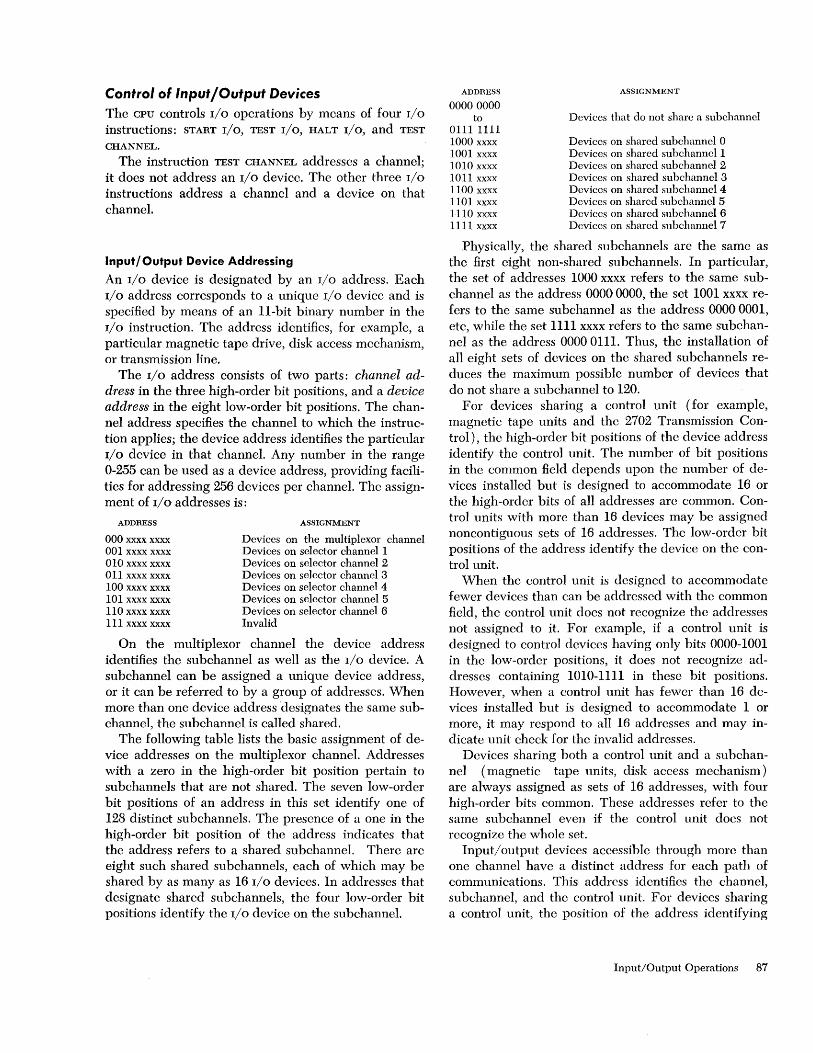
Control of Input/Output Devices The CPU controls I/O operations by means of four I/O
instructions: START I/O, TEST I/O, HALT I/O, and TEST
CHANNEL.
The instruction TEST CHANNEL addresscs a channel; it does not address an I/O device. The other three I/O
instructions address a channel and a device on that channel.
Input/Output Device Addressing
An I/O device is designated by an I/O address. Each I/O address corresponds to a unique I/O device and is specified by means of an II-bit binary number in the I/O instruction. The address identifies, for example, a particular magnetic tape drive, disk access mcchanism, or transmission line.
The I/O address consists of two parts: channel address in the three high-order bit positions, and a device address in the eight low-order bit positions. The channel address specifies the channel to which the instruction applies; the device address identifies the particular I/O device in that channel. Any number in the range 0-255 can be used as a device address, providing facilities for addressing 256 devices per channel. The assignment of I/O addresses is:
ADDRESS
000 xxxx xxxx 001 xxxx xxxx 010 xxx x xxxx 011. xxxx xxxx 1. 00 xxxx xxxx 101 xxx x xxxx 11 0 xxxx xxxx 111 xxxx xxxx
ASSIGNMENT
Devices on the multiplexor channel Devices on selector channel 1 Devices on selector channel 2 Devices on selector channel 3 Devices on selector channel 4 Devices on selector channel 5 Devices on selector channel 6 Invalid
On the multiplexor channel the device address identifies the su bchannel as well as the I/O device. A subchannel can be assigned a unique device address, or it can be referred to by a group of addresses. When more than one device address 'designates the same subchannel, the subchannel is called shared.
The following table lists the basic assignment of device addresses on the multiplexor channel. Addresses with a zero in the high-order bit position pertain to subchannels that are not shared. The seven low-order bit positions of an address in this set identify one of 128 distinct subchannels. The presence of a one in the high-order bit position of the address indicates that the address refers to a shared sub channel. There are eight such shared subchannels, each of which may be shared by as many as 16 I/O devices. In addresses that designate shared subchannels, the four low-order bit positions identify the I/O device on the subchannel.
ADDRESS
00000000 to
0111 1111 1000 xxxx 1001 xxxx 1.010 xxxx 1011 xxxx 1100 xxxx 1101. xxxx 1110 xxxx 1111 xxxx
ASSIGNMENT
Devices that do not share a subchannel
Devices on shared subchanncl 0 Devices on shared subchannel 1 Devices on shared subchanncl 2 Devices on shared subchannel 3 Devices on shared subchannel 4 Devices on shared subchannel 5 Devices on shared subchanncl 6 Devices on shared subchannel 7
Physically, the shared subchannels are the same as the first eight non-shared subchannels. In particular, the set of addresses 1000 xxxx refers to the same subchannel as the address 00000000, the set 1001 xxxx refers to the same sub channel as the address 0000 0001, etc, while the set 1111 xxxx refers to the same subchannel as the address 00000111. Thus, the installation of all eight sets of devices on the shared subchannels reduces the maximum possible number of devices that do not share a subchannel to 120.
For devices sharing a control unit (for example, magnetic tape units and the 2702 Transmission Control), the high-order bit positions of the device address identify the control unit. The number of bit positions in the common field depends upon the number of devices installed but is designed to accommodate 16 or the high-order bits of all addresses are common. Control units with more than 16 devices may be assigned noncontiguous sets of 16 addresses. The low-order bit positions of the address identify the device on the control unit.
When the control unit is designed to accommodate fewer devices than can be addressed with the common field, the control unit does not recognize the addresses not assigned to it. For example, if a control unit is designed to control devices having only bits 0000-1001 in the low-order positions, it does not recognize addresses containing 1010-1111 in these bit positions. However, when a contra] unit has fewer than 16 devices installed but is designed to accommodate 1 or more, it may respond to all 16 addresses and may indicate unit check for the invalid addresses.
Devices sharing both a control unit and a subchannel ( magnetic tape units, disk access mechanism) are always assigned as sets of 16 addresses, with four high-order bits common. These addresses refer to the same sub channel even if the control unit does not recognize the whole set.
Input! output devices accessible through more than one channel have a distinct address for each path of communications. This address identifies the channel, sub channel, and the control unit. For devices sharing a control unit, the position of the address identifying
Input/Output Operations 87
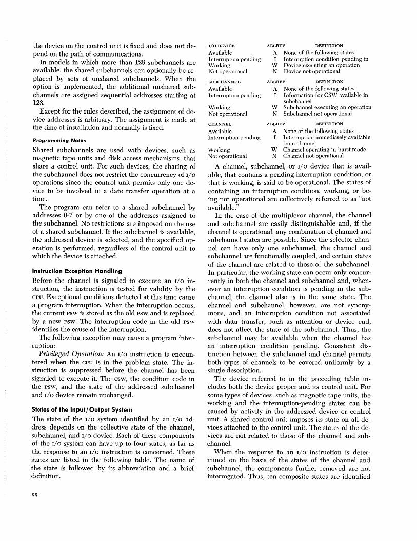
the device on the control unit is fixed and does not depend on the path of communications.
In models in which more than 128 sub channels are available, the shared subchannels can optionally be replaced by sets of unshared subchannels. When the option is implemented, the additional unshared subchannels are assigned sequential addresses starting at 128.
Except for the rules described, the assignment of device addresses is arbitrary. The assignment is made at the time of installation and normally is fixed.
Programmill1g Notes
Shared subchannels are used with devices, such as magnetic tape units and disk access mechanisms, that share a control unit. For such devices, the sharing of the subchannel does not restrict the concurrency of I/O
operations since the control unit permits only one device to be involved in a date transfer operation at a time.
The program can refer to a shared sub channel by addresses 0-7 or by one of the addresses assigned to the subchannel. No restrictions are imposed on the use of a shared subchannel. If the subchannel is available, the addressed device is selected, and the specified operation is performed, regardless of the control unit to which the device is attached.
Instruction Exception Handling
Before the channel is signaled to execute an I/O instruction, the instruction is tested for validity by the CPU. Exceptional conditions detected at this time cause a program interruption. When the interruption occurs, the current psw is stored as the old psw and is replaced by a new psw. The interruption code in the old psw identifies the cause of the interruption.
The following exception may cause a program interruption:
Privileged Operation: An I/O instruction is encountered when the CPU is in the problem state. The instruction :is suppressed before the channel has been signaled to execute it. The csw, the condition code in the psw, and the state of the addressed sub channel and I/O device remain unchanged.
States of the Input/Output System
The state of the I/O system identified by an I/O address depends on the collective state of the channel, sub channel, and I/O device. Each of these components of the I/O system can have up to four states, as far as the response to an I/O instruction is concerned. These states are listed in the following table. The name of the state is followed by its abbreviation and a brief definition.
88
I/O DEVICE
Available Interruption pending Working Not operational
SUDCHANNEL
Available Interruption pending
Working Not operational
CHANNEL
Available Interruption pending
Working Not operational
ADBREV DEFINITION
A None of the following states I Interruption condition pending in
W Device executing an operation N Device not operational
ADDREV DEFINITION
A None of the following states I Information for CSW available in
subehannel W Subchannel executing an operation N Subchannel not operational
ADDREV DEFINITION
A None of the following states I Interruption immediately available
from channel W Channel operating in hurst mode N Channel not operational
A channel, subchannel, or I/O device that is available, that contains a pending interruption condition, or that is working, is said to be operational. The states of containing an interruption condition, working, or being not operational are collectively referred to as "not available."
In the case of the multiplexor channel, the channel and subchannel are easily distinguishable and, if the channel is operational, any combination of channel and subchanncl states are possible. Since the selector channel can have only one subchannel, the channel and subchannel are functionally coupled, and certain states of the channel are related to those of the subchannel. In particular, the working state can occur only concurrently in both the channel and subchannel and, whenever an interruption condition is pending in the subchannel, the channel also is in the same state. The channel and sub channel, however, are not synonymous, and an interruption condition not associated with data transfer, such as attention or device end, does not affect the state of the subchannel. Thus, the subchanne.1 may be available when the channel has an interruption condition pending. Consistent distinction between the subchannel and channel permits both types of channels to be covered uniformly by a single description.
The device referred to in the preceding table includes both the device proper and its control unit. For some types of devices, such as magnetic tape units, the working and the interruption-pending states can be caused by activity in the addressed device or control unit. A shared control unit imposes its state on all devices attached to the control unit. The states of the devices are not related to those of the channel and subchannel.
When the response to an I/O instruction is determined on the basis of the states of the channel and subchannel, the components further removed are not interrogated. Thus, ten composite states are identified
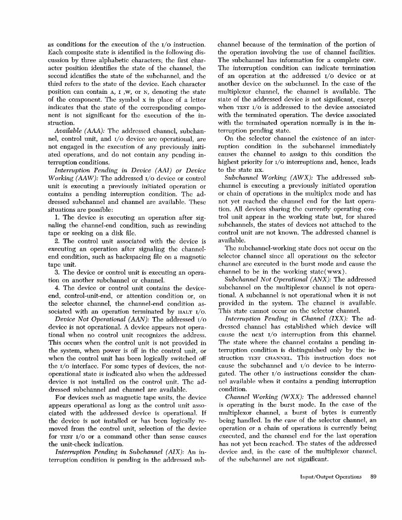
as conditions for the execution of the I/O instruction. Each composite state is identified in the following discussion by three alphabetic characters; the first character position identifies the state of the channel, the second identifies the state of the subchannel, and the third refers to the state of the device. Each character position can contain A, I ,w, or N, denoting the state of the component. The symbol x in place of a letter indicates that the state of the corresponding component is not significant for the execution of the instruction.
Available (AAA): The addressed channel, subchannel, control unit, and I/O device are operational, are not engaged in the execution of any previously initiated operations, and do not contain any pending interruption conditions.
Interruption Pending in Device (AAI) or Device Working (AA W): The addressed I/O device or control unit is executing a previously initiated operation or contains a pending interruption condition. The addressed sub channel and channel are available. These situations are possible:
1. The device is executing an operation after signaling the channel-end condition, such as rewinding tape or seeking on a disk file.
2. The control unit associated with the device is executing an operation after signaling the channelend condition, such as backspacing file on a magnetic tape unit.
3. The device or control unit is executing an operation on another sub channel or channel.
4. The device or control unit contains the deviceend, control-unit-end, or attention condition or, on the selector channel, the channel-end condition associated with an operation terminated by HALT I/O.
Device Not Operational (AAN): The addressed I/O
device is not operational. A device appears not operational when no control unit recognizes the address. This occurs when the control unit is not provided in the system, when power is off in the control unit, or when the control unit has been logically switched off the I/O interface. For some types of devices, the notoperational state is indicated also when the addressed device is not installed on the control unit. The addressed subchannel and channel are available.
For devices such as magnetic tape units, the device appears operational as long as the control unit associated with the addressed device is operational. If the device is not installed or has been logically removed from the control unit, selection of the device for TEST I/O or a command other than sense causes the unit-check indication.
Interruption Pending in Subchannel (AIX): An interruption condition is pending in the addressed sub-
channel because of the termination of the portion of the operation involving the use of channel facilities. The subchannel has information for a complete csw. The interruption condition can indicate termination of an operation at the addressed I/O device or at another device on the subchannel. In the case of the multiplexor channel, the channel is available. The state of the addressed device is not significant, except when TEST I/O is addressed to the device associated with the terminated operation. The device associated with the terminated operation normally is in the interruption pending state.
On the selector channel the existence of an interruption condition in the sub channel immediately causes the channel to assign to this condition the highest priority for I/O interruptions and, hence, leads to the state IIX.
Sub channel Working (AWX): The addressed subchannel is executing a previously initiated operation or chain of operations in the multiplex mode and has not yet reached the channel end for the last operation. All devices sharing the currently operating control unit appear in the working state but, for shared subchannels, the states of devices not attached to the control unit are not known. The addressed channel is available.
The sub channel-working state does not occur on the selector channel since all operations on the selector channel are executed in the burst mode and cause the channel to be in the working state ( wwx) .
Subchannel Not Operational (ANX): The addressed sub channel on the multiplexor channel is not operational. A subchannel is not operational when it is not provided in the system. The channel is available. This state cannot occur on the selector channel.
Interruption Pending in Channel (IXX): The addressed channel has established which device will cause the next I/O interruption from this channel. The state where the channel contains a pending interruption condition is distinguished only by the instruction TEST CHANNEL. This instruction does not cause the subchannel and I/O device to be interrogated. The other I/O instructions consider the channel available when it contains a pending interruption condition.
Channel Working (WXX): The addressed channel is operating in the burst mode. In the case of the multiplexor channel, a burst of bytes is currently being handled. In the case of the selector channel, an operation or a chain of operations is currently being executed, and the channel end for the last operation has not yet been reached. The states of the addressed device and, in the case of the multiplexor channel, of the sub channel are not significant.
Input/Output Operations 89

Channel Not Operational (NXX): The addressed channel is not operational, or the channel address in the instruction is invalid. A channel is not operational when it is not provided in the system or when it has been switched to the test mode. The states of the addressed I/O device and sub channel are not significant.
Resetting of the Input/Output System
Two types of resetting can occur in the I/O system. The reset states overlap the hierarchy of states distinguished for the purpose of responding to the CPU
during the execution of I/O instructions. Resetting terminates the current operation, disconnects the device from the channel, and may place the device in certain modes of operation. The meaning of the two reset states for each type of I/O device is specified in the Systems Reference Library (SRL) publication for the device.
System Re,set
The system-reset function is performed when the system-reset key is pushed, when initial program loading is performed, or when a system power-on sequence is completed.
System reset causes the channel to terminate operations on all subchannels. Status information and interruption conditions in the subchannels are reset, and all operational subchannels are placed in the available state. The channel sends the system-reset signal to all I/O devices attached to it.
If the device is! currently communicating over the I/O interface, the device immediately disconnects from the channel. Data transfer and any operation using the facilities of the control unit are immediately terminated, and the I/O device is not necessarily positioned at the beginning of a block. Mechanical motion not involving the use of the control unit, such as rewinding magnetic tape or positioning a disk access mechanism, proceeds to the normal stopping point, if possible. The device remains unavailable until the termination of mechanical motion or the inherent cycle of operation, if any, whereupon it becomes available" Status information in the device and control unit :is reset, and no interruption condition is generated upon completing the operation.
A control unit accessible by more than one channel is reset if it is currently associated with a channel on the CPU generating the reset.
Malfunction Reset
The malfunction-reset function is performed when the channel detects equipment malfunctioning.
90
Execution of malfunction reset in the channel depends on the type of error and the model. It may cause all operations in the channel to be terminated and all operational subchannels to be reset to the available state. The channel may send either the malfunction-reset signal to the device connected to the channel at the time the malfunctioning is detected, or channels sharing common equipment with the CPU may send the system-reset signal to all devices attached to the channel.
When the channel signals malfunction reset over the interface, the device immediately disconneots from the channel. Data transfer and any operation using the facilities of the control unit are immediately terminated, and the I/O device is not necessarily positioned at the beginning of a block. Mechanical motion not involving the control unit, such as rewinding magnetic tape or positioning a disk access mechanism, proceeds to the normal stopping point, if possible. The device remains unavailable until the termination of mechanical motion or the inherent cycle of operation, if any, whereupon it becomes available. Status information associated with the addressed device is reset, but an interruption condition may be generated upon completing any mechanical operation.
When a malfunction reset occurs, the program is alerted by an I/O interruption or, when the malfunction is detected during the execution of an I/O instruction, by the setting of the condition code. In either case the csw identifies the condition. The device addressed by the I/O instruction or the device identified by the I/O interruption, however, is not necessarily the one placed in the malfunction-reset state. In channels sharing common equipment with the CPU, malfunctioning detected by the channel may be indicated by a machine-check interruption, in which case a csw is not stored and a device is not identified. The method of identifying malfunctioning depends upon the model.
Condition Code
The results of certain tests by the channel and device, and the original state of the addressed part of the I/O
system are used during the execution of an I/O instruction to set one of four condition codes in bit positions 34 and 35 of the psw. The condition code is set at the time the execution of the instruction is completed, that is, the time the CPU is released to proceed with the next instruction. The condition code indicates whether or not the channel has performed the function specified by the instruction and, if not, the reason for the rejection. The code can be used for decision-making by subsequent branch-on-condition operations.

The following table lists the conditions that are identified and the corresponding condition codes for each instruction. The states of the system and their abbreviations are defined in "States of the Input/Output System." The digits in the table represent the numeric value of the code. The instruction START I/O
can set code 0 or 1 for the AAA state, depending on the type of operation that is initiated.
CONDITION CODE FOR
START TEST HALT TEST
CONDITIONS I/O I/O I/O CHAN
Available AAA O,P~ 0 0 0 Interruption pend. in device AAI 1~ 1~ 0 0 Device working AAW 1~ 1~ 0 0 Device not operational AAN 3 3 0 0 Interruption pend. in sub channel AIX
For the addressed device 2 1~ 0 0 For another device 2 2 0 0
Subchannel working AWX 2 2 1~ 0 Subchannel not operational ANX 3 3 3 0 Interruption pend. in channel IXX sce note below 1 Channel working WXX 2 2 2 2 Channel not operational NXX 3 3 3 3 Error
Channel equipment error P P 1~
Channel programming error 1~
Device error 1~ 1~
~The CSW or its status portion is stored at location 64 during execution of the instruction.
- The condition cannot be identified during execution of the instruction.
NOTE: For the purpose of executing START I/O, TEST I/O, and HALT I/O, a channel containing a pending interruption condition appears the same as an available channel, and the condition codes for the IXX state are the same as for the AXX state, where the X's represent the states of the subchannel and the device. As an example, the condition eode for the IAA state is the same as for the AAA state.
The available condition is indicated only when no errors are detected during the execution of the I/O
instruction. When a programming error occurs in the information placed in the CAW or ccw and the addressed channel or subchannel is working, either condition code 1 or 2 may be set, depending upon the model. Similarly, either code 1 or 3 may be set when a programming error occurs and a part of the addressed I/O system is not operational.
When a subchannel on the multiplexor channel contains a pending interruption condition (state AIX),
the I/O device associated with the terminated operation normally is in the interruption-pending state. When the channel detects during execution of TEST
I/O that the device is not operational, condition code 3 is set. Similarly, condition code 3 is set when HALT
I/O is addressed to a subchannel in the working state and operating in the multiplex mode (state A WX ) ,
but the device turns out to be not operational. The not-operational state in both situations can be caused
by operator intervention or by equipment malfunction and, for HALT I/O, may occur when the isntruction is addressed to a control unit other than the one currently operating.
The error conditions listed in the preceding table include all equipment or programming errors detected by the channel or the I/O device during execution of the I/O instruction. Except for channel equipment errors, in which case no csw may be stored, the status portion of the csw identifies the error. Three types of errors can occur:
Channel Equipment Error: The channel can detect the following equipment errors during execution of START r/o, TEST I/O, and HALT r/o:
1. The device address that the channel received on the interface during initial selection either has a parity error or is not the same as the one the channel sent out. Some device other than the one addressed may be malfunctioning.
2. The unit-status byte that the channel received on the interface during initial selection has a parity error.
3. A signal from the I/O device occurred during initial selection at an invalid time or had invalid duration.
4. The channel detected an error in its control equipment.
The channel may perform the malfunction-reset function, depending on the type of error and the model. If a csw is stored, channel control check or interface control check is indicated, depending on the type of error.
Channel Programming Error: The channel can detect the following programming errors during execution of START I/O:
1. Invalid ccw address in CAW
2. Invalid ccw address specification in CAW
3. Invalid storage protection key in CAW
4. Invalid CAW format 5. First ccw specifies transfer in channel 6. Invalid command code in first ccw 7. Initial data address exceeds addressing capacity
of model 8. Invalid count in first ccw 9. Invalid format of first ccw The csw indicates program check. Device Error: Programming or equipment crrors
detected by the device during the execution of START
I/O are indicated by unit check or unit exception in the csw. The instruction TEST I/O can cause unit check to be generated.
The conditions responsible for unit check and unit exception for each type of 1/0 device are detailed in the SRL publication for the device.
[nput/Output Operations 91
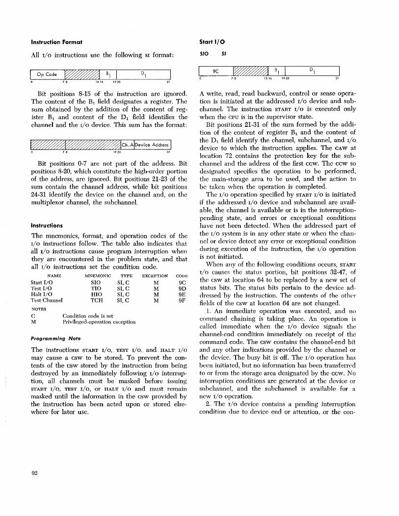
Instruction Format
All I/O instructions use the following SI format:
OpCode ~ B1 I 78 1516 1920 31
Bit positioIiS 8-15 of the instruction are ignored. The content of the Bl field designates a register. The sum obtained by the addition of the content of register Bl and content of the Dl field identifies the channel and the I/O device. This sum has the format:
Bit positions 0-7 are not part of the address. Bit positions 8-20, which constitute the high-order portion of the address, are ignored. Bit positions 21-23 of the sum contain the channel address, while bit positions 24-31 identify the device on the channel and, on the multiplexor channel, the subchannel.
Instructionls
The mnemonics, format, and operation codes of the I/O instructions follow. The table also indicates that all I/O instructions cause program interruption when they are encountered in the problem state, and that all I/O instructions set the condition code.
NAME MNEMONIC TYPE EXCEPTION CODE
Start 110 SIO SI, C M 9C Test 110 TIO SI, C M 9D Halt 110 HIO SI, C M 9E Test Channel TCH SI, C M 9F
NOTES
C Condition code is set M Privileged-operation exception
Programming Note
The instructions START I/O, TEST I/O, and HALT I/O may cause a csw to be stored. To prevent the contents of the csw stored by the instruction from being destroyed by an immediately following I/O interruption, all channels must be masked before issuing START I/O, TEST I/O, or HALT I/O and must remain masked until the information in the csw provided by the instruction has been acted upon or stored elsewhere for later use.
92
Start I/O
5/0 51
9C ~B1 7 8 1516 1920 31
A write, read, read backward, control or sense operation is initiated at the addressed I/O device and subchannel. The instruction START I/O is executed only when the CPU is in the supervisor state.
Bit positions 21-31 of the sum formed by the addition of the content of register Bl and the content of the Dl field identify the channel, sub channel, and I/O device to which the instruction applies. The CAW at location 72 contains the protection key for the subchannel and the address of the first ccw. The ccw so designated specifies the operation to be performed, the main-storage area to be used, and the action to be taken when the operation is completed.
The I/O operation specified by START I/O is initiated if the addressed I/O device and subchannel are available, the channel is available or is in the interruptionpending state, and errors or exceptional conditions have not been detected. When the addressed part of the I/O system is in any other state or when the channel or device detect any error or exceptional condition during exccution of the instruction, the I/O operation is not initiated.
When any of the following conditions occurs, START I/O causes the status portion, bit positions 32-47, of the csw at location 64 to be replaced by a new set of status bits. The status bits pertain to the device addressed by the instruction. The contents of the other fields of the csw at location 64 are not changed.
1. An immediate operation was executed, and no command chaining is taking place. An operation is called immediate when the I/O device signals the channel-end condition immediately on receipt of the command code. The csw contains the channel-end bit and any other indications provided by the channel or the device. The busy bit is off. The I/O operation has been initiated, but no information has been transferred to or from the storage area designated by the ccw. No interruption conditions are generated at the device or snbchannel, and the sub channel is available for a new I/O operation.
2. The I/O device contains a pending interruption condition due to device end or attention, or the con-
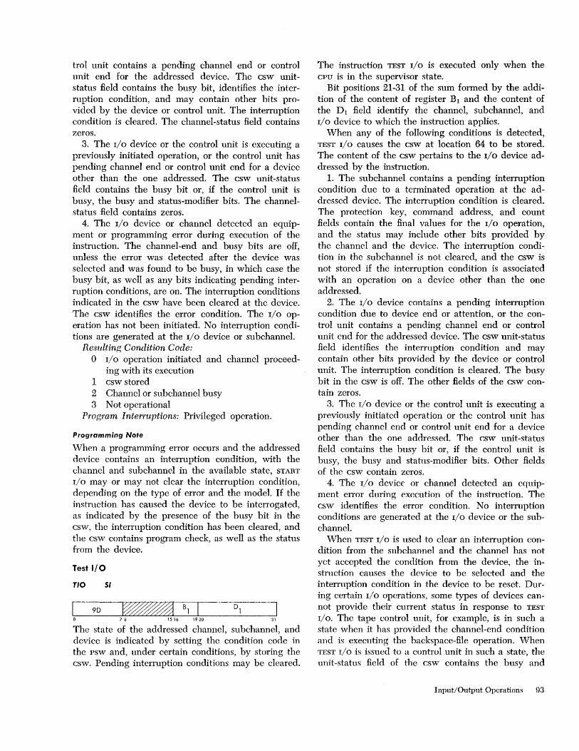
trol unit contains a pending channel end or control unit end for the addressed device. The csw unitstatus field contains the busy bit, identifies the interruption condition, and may contain other bits provided by the device or control unit. The interruption condition is cleared. The channel-status field contains zeros.
3. The I/O device or the control unit is executing a previously initiated operation, or the control unit has pending channel end or control unit end for a device other than the one addressed. The csw unit-status field contains the busy bit or, if the control unit is busy, the busy and status-modifier bits. The channelstatus field contains zeros.
4. The I/O device or channel detected an equipment or programming error during execution of the instruction. The channel-end and busy bits are off, unless the error was detected after the device was selected and was found to be busy, in which case the busy bit, as well as any bits indicating pending interruption conditions, are on. The interruption conditions indicated in the csw have been cleared at the device. The csw identifies the error condition. The I/O operation has not been initiated. No interruption conditions are generated at the I/O device or subchannel.
Resulting Condition Code: o I/O operation initiated and channel proceed-
ing with its execution 1 csw stored 2 Channel or sub channel busy 3 Not operational
Program Interruptions: Privileged operation.
Programming Note
When a programming error occurs and the addressed device contains an interruption condition, with the channel and subchannel in the available state, START
I/O mayor may not clear the interruption condition, depending on the type of error and the model. If the instruction has caused the device to be interrogated, as indicated by the presence of the busy bit in the csw, the interruption condition has been cleared, and the csw contains program check, as well as the status from the device.
Test I/O
rio 51
9D ~Bll 78 1516 1920 31
The state of the addressed channel, subchannel, and device is indicated by setting the condition code in the psw and, under certain conditions, by storing the csw. Pending interruption conditions may be cleared.
The instruction TEST I/O is executed only when the CPU is in the supervisor state.
Bit positions 21-31 of the sum formed by the addition of the content of register Bl and the content of the Dl field identify the channel, subchannel, and I/O device to which the instruction applies.
When any of the following conditions is detected, TEST I/O causes the csw at location 64 to be stored. The content of the csw pertains to the I/O device addressed by the instruction.
1. The subchannel contains a pending interruption condition due to a terminated operation at the addressed device. The interruption condition is cleared. The protection key, command address, and count fields contain the final values for the I/O operation, and the status may include other bits provided by the channel and the device. The interruption condition in the subchannel is not cleared, and the csw is not stored if the interruption condition is associated with an operation on a device other than the one addressed.
2. The I/O device contains a pending interruption condition due to device end or attention, or the control unit contains a pending channel end or control unit end for the addressed device. The csw unit-status field identifies the interruption condition and may contain other bits provided by the device or control unit. The interruption condition is cleared. The busy bit in the csw is off. The other fields of the csw contain zeros.
3. The I/O device or the control unit is executing a previously initiated operation or the control unit has pending channel end or control unit end for a device other than the one addressed. The csw unit-status field contains the busy bit or, if the control unit is busy, the busy and status-modifier bits. Other fields of the csw contain zeros.
4. The I/O device or channel detected an equipment error during execution of the instruction. The csw identifies the error condition. No interruption conditions are generated at the I/O device or the subchannel.
When TEST I/O is used to clear an interruption condition from the subchannel and the channel has not yet accepted the condition from the device, the instruction causes the device to be selected and the interruption condition in the device to be reset. During certain I/O operations, some types of devices cannot provide their current status in response to TEST
I/O. The tape control unit, for example, is in such a state when it has provided the channel-end condition and is executing the backspace-file operation. When TEST I/O is issued to a control unit in such a state, the unit-status field of the csw contains the busy and
Input/Output Operations 93
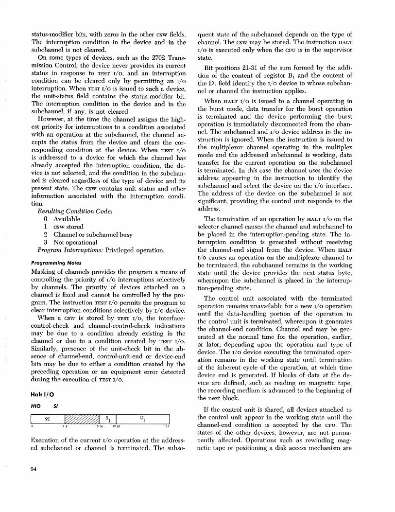
status-modifier bits, with zeros in the other csw fields. The interruption condition in the device and in the subchannel is not cleared.
On some types of devices, such as the 2702 Transmission Control, the device never provides its current status in response to TEST I/O, and an interruption condition can be cleared only by permitting an I/O
interruption. When TEST I/O is issued to such a device, the unit-status field contains the status-modifier bit. The interruption condition in the device and in the subchannel, if any, is not cleared.
However, at the time the channel assigns the highest priority for interruptions to a condition associated with an operation at the subchannel, the channel accepts the status from the device and clears the corresponding condition at the device. When TEST I/O
is addressed to a device for which the channel has already accepted the interruption condition, the device is not selected, and the condition in the subchannel is cleared regardless of the type of device and its present state. The csw contains unit status and other information associated with the interruption condition.
Resulting Condition Code: o Available 1 csw stored 2 Channel or subchannel busy 3 Not operational
Program Interruptions: Privileged operation.
Programming Notes
Masking of channels provides the program a means of controlling the priority of I/O interruptions selectively by channels. The priority of devices attached on a channel is fixed and cannot be controlled by the program. The instruction TEST I/O permits the program to clear interruption conditions selectively by I/O device.
When a csw is stored by TEST I/O, the interfacecontrol-check and channel-control-check indications may be due to a condition already existing in the channel or due to a condition created by TEST I/O.
Similarly, presence of the unit-check bit in the absence of channel-end, control-unit-end or device-end bits may be due to either a condition created by the preceding operation or an equipment error detected during the execution of TEST I/O.
Halt I/O
HIO 51
9E ~Bl 78 1516 1920 31
Execution of the current I/O operation at the addressed sub channel or channel is terminated. The subse-
94
quent state of the subchannel depends on the type of channel. The csw may be stored. The instruction HALT
I/O is executed only when the CPU is in the supervisor state.
Bit positions 21-31 of the sum formed by the addition of the content of register Bl and the content of the Dl field identify the I/O device to whose subchannel or channel the instruction applies.
When HALT I/O is issued to a channel operating in the burst mode, data transfer for the burst operation is terminated and the device performing the burst operation is immediately disconnected from the channel. The subchannel and I/O device address in the instruction is ignored. When the instruction is issued to the multiplexor channel operating in the multiplex mode and the addressed subchannel is working, data transfer for the current operation on the subchannel is terminated. In this case the channel uses the device address appearing in the instruction to identify the subchanncl and select the device on the I/O interface. The address of the device on the subchannel is not significant, providing the control unit responds to the address.
The termination of an operation by HALT I/O on the selector channel causes the channel and su bchannel to be placed in the interruption-pending state. The interruption condition is generated without receiving the channel-end signal from the device. When HALT
I/O causes an operation on the multiplexor channel to be terminated, the subchannel remains in the working state until the device provides the next status byte, whereupon the subchannel is placed in the interruption-pending state.
The control unit associated with the terminated operation remains unavailable for a new I/O operation until the data-handling portion of the operation in the control unit is terminated, whereupon it generates the channel-end condition. Channel end may be generated at the normal time for the operation, earlier, or later, depending upon the operation and type of device. The I/O device executing the terminated operation remains in ,the working state until termination of the inherent cycle of the operation, at which time device end is generated. If blocks of data at the device are defined, such as reading on magnetic tape, the recording medium is advanced to the beginning of the next block.
If the control unit is shared, all devices attached to the control unit appear in the working state until the channel-end condition is accepted by the CPU. The states of the other devices, however, are not permanently affected. Operations such as rewinding magnetic tape or positioning a disk access mechanism are
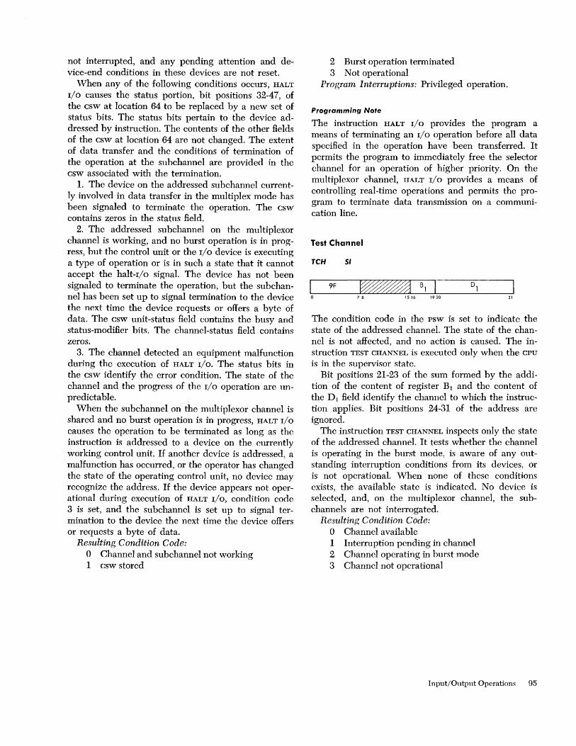
not interrupted, and any pending attention and device-end conditions in these devices are not reset.
When any of the following conditions occurs, HALT
I/O causes the status portion, bit positions 32-47, of the csw at location 64 to be replaced by a new set of status bits. The status bits pertain to the device addressed by instruction. The contents of the other fields of the csw at location 64 are not changed. The extent of data transfer and the conditions of termination of the operation at the subchannel are provided in the csw associated with the termination.
1. The device on the addressed subchannel currently involved in data transfer in the multiplex mode has been signaled to terminate the operation. The csw contains z,eros in the status field.
2. The addressed subchannel on the multiplexor channel is working, and no burst operation is in progress, but the control unit or the I/O device is executing a type of operation or is in such a state that it cannot accept the halt-I/o signaI. The device has not been signaled to terminate the operation, but the subchannel has been set up to signal termination to the device the next time the device requests or offers a byte of data. The csw unit-status field contains the busy and status-modifier bits. The channel-status field contains zeros.
3. The channel detected an equipment malfunction during the execution of HALT I/O. The status bits in the csw identify the error condition. The state of the channel and the progress of the I/O operation are unpredictable.
When the subchannel on the multiplexor channel is shared and no burst operation is in progress, HALT I/O causes the operation to be terminated as long as the instruction is addressed to a device on the currently working control unit. If another device is addressed, a malfunction has occurred, or the operator has changed the state of the operating control unit, no device may recognize the address. If the device appears not operational during execution of HALT I/O, condition code 3 is set, and the subchannel is set up to signal termination to the device the next time the device offers or requests a byte of data.
Resulting Condition Code: o Channel and subchannel not working 1 csw stored
2 Burst operation terminated 3 Not operational
Program Interruptions: Privileged operation.
Programming Note
The instruction HALT I/O provides the program a means of terminating an I/O operation before all data specified in the operation have been transferred. It permits the program to immediately free the selector channel for an operation of higher priority. On the multiplexor channel, HALT I/O provides a means of controlling real-time operations and permits the program to terminate data transmission on a communication line.
Test Channel
TCH 51
9F ~Bl 78 1516 1920 31
The condition code in the psw is set to indicate the state of the addressed channeI. The state of the channel is not affected, and no action is caused. The instruction TEST CHANNEL is executed only when the CPU
is in the supervisor state. Bit positions 21-23 of the sum formed by the addi
tion of the content of register Bl and the content of the Dl field identify the channel to which the instruction applies. Bit positions 24-31 of the address are ignored.
The instruction TEST CHANNEL inspects only the state of the addressed channeI. It tests whether the channel is operating in the burst mode, is aware of any outstanding interruption conditions from its devices, or is not operationaI. When none of these conditions exists, the available state is indicated. No device is selected, and, on the multiplexor channel, the subchannels are not interrogated.
Resulting Condition Code: o Channel available 1 Interruption pending in channel 2 Channel operating in burst mode 3 Channel not operational
Input/Output Operations 95
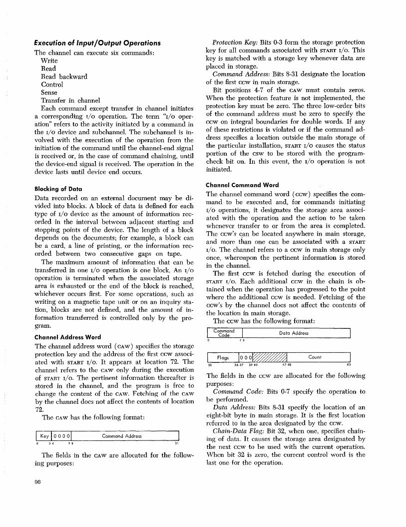
Execution of Input/Output Operations The channel can execute six commands:
Write Read Read backward Control Sense Transfer in channel Each command except transfer in channel initiates
a corresponding I/O operation. The term "I/O operation" refers to the activity initiated by a command in the I/O device and subchannel. The subchannel is involved with the execution of the operation from the initiation of the command until the channel-end signal is received or, in the case of command chaining, until the device-end signal is received. The operation in the device lasts until device end occurs.
Blocking of Data
Data recorded on an external document may be divided into blocks. A block of data is defined for each type of 110 device as the amount of information recorded in the interval between adjacent starting and stopping points of the device. The length of a block depends on the documents; for example, a block can be a card, a line of printing, or the information recorded between two consecutive gaps on tape.
The maximum amount of information that can be transferred in one I/O operation is one block. An I/O
operation is terminated when the associated storage area is exhausted or the end of the block is reached whichever occurs first. For some operations, such a~ writing on a magnetic tape unit or on an inquiry station, blocks are not defined, and the amount of information transferred is controlled only by the program.
Channel Address Word
The channel address word ( CAW) specifies the storage protection key and the address of the first ccw associated with START I/O. It appears at location 72. The channel refers to the CAW only during the execution of START I/O. The pertinent information thereafter is stored in the channel, and the program is free to change the content of the CAW. Fetching of the CAW by the channel does not affect the contents of location 72.
The CAW has the following format:
I Key I 0 () 0 0 I Command Address
o 34 78 31
The fields in the CAW are allocated for the following purposes:
96
Protection Key: Bits 0-3 form the storage protection key for all commands associated with START I/O. This key is matched with a storage key whenever data are placed in storage.
Command Address: Bits 8-31 designate the location of the first ccw in main storage.
Bit positions 4-7 of the CAW must contain zeros. When the protection feature is not implemented, the protection key must be zero. The three low-order bits of the command address must be zero to specify the ccw on integral boundaries for double words. If any of these restrictions is violated or if the command address specifies a location outside the main storage of the particular installation, START I/O causes the status portion of the csw to be stored with the programcheck bit on. In this event, the I/O operation is not initiated.
Channel Command Word
The channel command word (ccw) specifies the command to be executed and, for commands initiating I/O operations, it designates the storage area associated with the operation and the action to be taken whenever transfer to or from the area is completed. The ccw' s ~an be located anywhere in main storage, and more than one can be associated with a START I/O. The channel refers to a ccw in main storage only once, whereupon the pertinent information is stored in the channel.
The first ccw is fetched during the execution of START I/O. Each additional ccw in the chain is obtained when the operation has progressed to the point where the additional ccw is needed. Fetching of the CCw's by the channel does not affect the contents of the location in main storage.
The ccw has the following format:
I Command . Code Data Address o 78
Flags looO~ Count
32 36 37 3940 4748 63
The fields in the ccw are allocated for the following purposes:
Command Code: Bits 0-7 specify the operation to he performed.
Data Address: Bits 8-31 specify the location of an eight-bit byte in main storage. It is the first location referred to in the area designated by the ccw.
Chain-Data Flag: Bit 32, when one, specifies chaining of data. It causes the storage area designated by the next ccw to be used with the current operation. Whcn bit 32 is zero, the current control word is the last one for the operation.

Chain-Command Flag: Bit 33, when one and when the chain-data flag is off, specifics chaining of commands. It causes the operation specified by the command code in the next ccw to be initiated on normal completion of the current operation. Whcn bit 33 is zero or when the CD flag is one, the next ccw docs not specify a new command.
Suppress-Length-Indication Flag: Bit 34 controls whether an incorrect length condition is to be indicated to the program. When this bit is one and the CD
flag is off in the last ccw used, the incorrect-length indication is suppressed. If the ccw has the cc flag on, command chaining takes place. Absence of the SLI flag or the presence of the CD flag causes the program to be notified of the incorrect-length condition when it occurs.
Skip Flag: Bit 35, when one, specifies suppression of transfer of information to storage during a read, read-backward, or sense operation. When bit 35 is zero, normal transfer of data takes place.
Program-Controlled-Interruption Flag: Bit 36, when one, causes the channel to generate an interruption condition upon fetching the ccw. When bit 36 is zero, normal operation takes place.
Count: Bits 48-63 specify the number of eight-bit byte locations in the storage area designated by the ccw.
Bit positions 37-39 of every ccw other than one specifying transfer in channel must contain zeros. Violation of this restriction generates the program-check condition. When the first ccw designated by the CAW
does not contain the required zeros, thc I/O operation is not initiated, and the status portion of the csw with the program-check indication is stored during execution of START I/O. Detection of this condition during data chaining causes the I/O device to be signaled to terminate the operation. When the absence of these zeros is detected during command chaining, the new operation is not initiated, and no interruption condition is generated.
The content of bit positions 40-47 of the ccw is ignored.
Command Code
The command code in the ccw specifies to the channel and the I/O device the operation to be performed.
The two low-order bits or, when these bits are 00, the four low-order bits of the command code identify the operation to the channel. The channel distinguishes among the following four operations:
Output forward (write, control) Input forward (read, sense) Input backward (read backward) Branching (transfer in channel)
The channel ignores the high-order bits of the command code.
Commands that initiate I/O operations (write, read, read backward, control, and sense) cause all eight bits of the command code to be transferred to the I/O device. In these command codcs, the high-order bit positions contain modifier bits. The modifier bits specify to the device how the command is to he executed. They may cause, for example, the device to compare data rcceived during a write operation with data previously recorded, and they may specify such conditions as recording density and parity. For the control command, the modifier bits may contain thc order code specifying the control function to be performed. The meaning of the modifier bits depends on the type of I/O device and is specified in the SRL publication for the device.
The command code assignment is listed in the fo]lowing table. The symhol x indicates that the bit position is ignored; m identifies a modifier hit.
CODE
X X X X 0000
MMMM 0100
x x x x 1000
MMMM 1100
MMMMMMOI
MMMMMM10
MMMMMM11
COMMAND
Invalid Sense Transfer in channel Read hackward \Vritc Read Control
Whenever the channel detects an invalid command code during the initiation of a command, the program-check condition is generated. When the first ccw designated by the CAW contains an invalid command code, the status portion of the csw with the programcheck indication is stored during execution of START
I/O. When the invalid code is detected during command chaining, the new operation is not initiated, and an interruption condition is generated. The command code is ignored during -data chaining, unless it specifies transfer in channel.
Definition of Storage Area
The main-storage area associated with an I/O operation is defined by ccw's. A ccw defines an area by specifying the address of the first eight-bit hyte to be transferred and the number of consecutive eight-bit bytes contained in the area. The address of the first hyte appears in the data-address field of the ccw. The number of bytes contained in the storage area is specified in the count field.
In write, read, control, and sense operations storage locations are used in ascending order of addresses. As information is transferred to or from main storage, the content of the address field is incremented, and the content of the count field is decrementcd .. The readbackward operation causes data to be placed in stor-
Input/Output Operations 97
age in a descending order of addresses, and both the count and the address are stepped down. When the count in any operation reaches zero, the storage area defined by the ccw is exhausted.
Any main-storage location provided in the system can be used to transfer data to or from an I/O device, provided that during an input operation the location is not protected. Similarly, the ccw's can be specified in any part of available main storage. When the channel attempts to store data at a protected location, the protection-check condition is generated, and the device is signaled to terminate the operation.
When the channel refers to a location not provided in the system, the program-check condition is generated. When this condition occurs because the first ccw designated by the CAW contains a data address exceeding the addressing capacity of the model, the I/O
operation is not initiated, and the status portion of the csw with the program-check indication is stored during execution of START I/O. Invalid data addresses detected after initiation of the opcration or detection of an invalid ccw address during chaining is indicated to the program with the interruption conditions at the termination of the operation or chain of operations.
During an output operation, thc channel may fetch data from main storage ahead of the time the I/O device requests the data. As many as 16 bytes may be prefetehed and buffered. Similarly, on data chaining during an output operation, the channel may fetch the new ccw when as many as 16 bytes remain to be transferred under the control of the current ccw. When the I/O operation uses data and ccw's from 10-ations near the end of the available storage, such prefetching may cause the channel to refer to locations that do not exist. Invalid addresses detected during prefetching of data or ccw's do not affect the execution of the operation and do not cause error indications until the I/O operation actually attempts to use the information. If the operation is terminated by the I/O device or by HALT I/O before the invalid information is needed, the condition is not brought to the attention of the program.
Storage addresses do not wrap around to location 0 unless the system has the maximum addressable storage (16,777,216 bytes). When the maximum addressable storage is provided, location 0 follows location 16,777,215 and, on reading backward, location 16,777,215 follows location O.
The count field in the ccw can specify any number of bytes up to 65,535. Except for a ccw specifying transfer in channel, it may not contain the value zero. Whenever the count field in the ccw initially contains a zero, the program-check condition is generated. When this occurs in the first ccw designated by the
98
CAW, the operation is not initiated, and the status portion of the csw with the program-check indication is stored during execution of START I/O. When a count of zero is detected during data chaining, the I/O device is signaled to terminate the operation. Detection of a count of zero during command chaining suppresses initiation of the new operation and generates an interruption condition.
Chaining
When the channel has performed the transfer of information specified by a ccw, it can continue the activity initiated by START I/O by fetching a new ccw. The fetching of a new ccw upon the exhaustion of the current ccw is called chaining and the ccw's belonging to such a sequence are said to be chained.
Chaining takes place only between ccw's located in successive double-word locations in storage. It proceeds in an ascending order of addresses; that is, the address of the new ccw is obtained by adding eight to the address of the current ccw. Two chains of ccw's located in noncontiguous storage areas can be coupled for chaining purposes by a transfer in channel command. All ccw's in a chain apply to the I/O
device specified in the original START I/O.
Two types of chaining are provided: chaining of data and chaining of commands. Chaining is controlled by the chain-data (CD) and chain-command (cc) flags in the ccw. These flags specify the action to be taken by the channel upon the exhaustion of the current ccw. The following code is used:
CD CC ACTION
o 0 No chaining. The current CCW is the last. o 1 Command chaining 1 0 Data chaining 1 1 Data chaining
The specification of chaining is effectively propagated through a transfer in channel command. When in the process of chaining a transfer-in-channel command is fetched, the ccw designated by the transfer in channel is used for the type of chaining specified in the ccw preceding the transfer in channel.
The CD and cc flags are ignored in the transfer-inchannel command.
Data Chaining
During data chaining, the new ccw fetched by the channel defines a new storage area for the original I/O
operation. Execution of the operation at the I/O device is not affected. Data chaining occurs only when all data designated by the current ccw have been transferred to or from the device and causes the operation to continue, using the storage area designated by the new
ccw. The content of the command-code field of the new ccw is ignored, unless it specifies transfer in channel.
Data chaining is considered to occur immediately after the last byte of data designated by the current ccw has been transferred to or from the device. When the last byte has been placed in main storage or accepted by the device, the new ccw takes over the control of the operation and replaces the pertinent information in the subchannel. If the device sends channel end after exhausting the count of the current ccw but before transferring any data to or from the storage area designated by the new ccw, the csw associated with the termination identifies the new ccw.
If programming errors are detected h ... the new ccw or during its fetching, the program-check condition is generated, and the device is signaled to terminate the operation when it attempts to transfer data designatcd by the new ccw. If the device signals the channel-end condition before transferring any data designated by the new ccw, program check is indicated in the csw associated with the termination. Unless the address of the new ccw is invalid or programming errors are detected in an intervening transfer-in-channel command, the content of the csw pertains to the new ccw. A data address referring to a nonexistent area or, on reading, to a protected area causes an error indication only after the I/O device has attempted to transfer data to or from the invalid location, but an address exceeding the addressing capacity of the model is detected immediately upon fetching the ccw.
Data chaining during an input operation causes the new ccw to be fetched when all data designated by the current ccw have been placed in main storage. On an output operation, the channel may fetch the new ccw from main storage ahead of the time data chaining occurs. The earliest such prefetching may occur is when 16 bytes still remain to be transferred under the control of the current ccw. Any programming errors in the prefetched ccw, however, do not affect the execution of the operation until all data designated by the current ccw have been transferred to the I/O device. If the device terminates the operation before all data designated by the current ccw have been transferred, the conditions associated with the prefetched ccw are not indicated to the program.
Only one ccw describing a data area may be prefetched and buffered in the channel. If the prefetched ccw specifies transfer in channel, only one more ccw is fetched before the exhaustion of the current ccw.
Programming Notes
Data chaining permits information to be rearranged as it is transferred between main storage and the I/O
device. Data chaining also permits a block of information to be transferred to or from noncontiguous areas of storage, and, when used in conjunction with the skipping function, it permits the program to place in storage selected portions of a block of data.
When during an input operation, the program specifies data chaining to a location into which data have been placed under the control of the current ccw, the channel fetches the new contents of the location, even if the location contains the last byte transferred under thc control of the current ccw. The program, therefore, can use self-describing records; that is, it can chain to a ccw that has been read under the control of the current ccw. However, since the program is not notified of any data errors until the end of the operation, there is no assurance that the ccw is correct. The ccw in main storage may be invalid even though its parity is good.
Command Chaining
During command chaining, the new ccw fetched by the channel specifies a new I/O operation. The channel fetches the new ccw and initiates the new operation upon the receipt of the device-end signal for the current operation. When command chaining takes place, the completion of the current operation does not cause an I/O interruption, and the count indicating the amount of data transferred during the current operation is not made available to the program. For operations involving data transfer, the new command always applies to the next block at the device.
Command chaining takes place and the new operation is initiated only if no unusual conditions have been detected in the current operation. If a condition such as unit check, unit exception, or incorrect length has occurred, the sequence of operations is terminated, and the status associated with the current operation causes an interruption condition to be generated. The new ccw in this case is not fetched. The incorrect-length condition does not suppress command chaining if the current ccw has the SLI Hag on.
An exception to sequential chaining of ccw's occuts when the I/O device presents the status-modifier condition with the device-end signal. When command chaining is specified and no unusual conditions have been detected, the combination of status-modifier and device-end bits causes the channel to fetch and chain to the ccw whose main-storage address is 16 higher than that of the current ccw.
When both command and data chaining are used, the first ccw associated with the operation specifies the operation to be executed, and the last ccw indicates whether another operation follows.
Input/Output Operations 99

Programming Note
Command chaining makes it possible for the program to initiate transfer of multiple blocks of data by means of a single START I/O. It also permits a sub channel to be set up for execution of auxiliary functions, such as positioning the disk access mechanism, and for data transfer operations without interference by the program at the end of each operation. Command chaining, in conjunction with the status-modifier condition, permits the channel to modify the normal sequence of operations in response to signals provided by the I/O
device.
Skipping
Skipping is the suppression of main-storage references during an I/O operation. It is defined only for read, read backward, and sense operations and is controlled by the skip Bag, which can be specified individually for each ccw. When the skip Hag is one, skipping occurs; when zero, normal operation takes place. The setting of the skip flag is ignored in all other operations.
Skipping affects only the handling of information by the channel. The operation at the I/O device proceeds normally, and information is transferred to the channel. The channel keeps updating the count but does not place the information in main storage. If the chain-command or chain-data flag is one, a new ccw is obtained when the count reaches zero. In the case of data chaining, normal operation is resumed if the skip Hag in the new ccw is zero.
No checking for invalid or protected data addresses takes place during skipping, except that the initial data address in the ccw cannot exceed the addressing capacity of the model.
Programming Note
Skipping, when combined with data chaining, permits the program to place in main storage selected portions of a block of information from an I/O device.
Program-Controlled Interruption
The program-controlled interruption ( PCI) function permits the program to cause an I/O interruption during execution of an I/O operation. The function is controlled by the PCI flag in the ccw. The flag can be on either in the first ccw specified by START I/O or in a ccw fetched during chaining. Neither the PCI Hag nor the associated interruption affects the execution of the current operation.
Whenever the PCI Hag in the ccw is on, the channel attempts to interrupt the program. When the first ccw associated with an operation contains the PCI Bag,
100
either initially or upon command chaining, the interruption may occur as early as immediately upon the initiation of the operation. The PCI flag in a ccw fetched on data chaining causes the interruption to occur after all data designated by the preceding ccw have been transferred. The time of the interruption, however, depends on the model and the current activity in the system and may be delayed even if the channel is not masked. No predictable relation exists between the time the interruption due to the PCI Hag occurs and the progress of data transfer to or from the area designated by the ccw.
If chaining occurs before the interruption due to the PCI flag has taken place, the PCI condition is carried over to the new ccw. This carryover occurs both on data and command chaining and, in either case, the condition is propagated through the transfer-inchannel command. The PCI conditions are not stacked; that is, if another ccw is fetched with a PCI Bag before the interruption due to the PC! Hag of the previous ccw has occurred, only one interruption takes place.
A csw containing the PCI bit may be stored by an interruption while the operation is still proceeding or upon the termination of the operation.
When the csw is stored by an interruption before the operation or chain of operations has been terminated, the command address is eight higher than the address of the current ccw, and the count is unpredictable. All unit-status bits in the csw are off. If the channel has detected any unusual conditions, such as channel data check, program check, or protection check by the time the interruption occurs, the corresponding channel-status bit is on, although the condition in the channel is not reset and is indicated again upon the termination of the operation.
Presence of any unit-status bit in the csw indicates that the operation or chain of operations has been terminated. The csw in this case has its regular format with the PCI bit added.
The setting of the PCI Bag is inspected in every ccw except those specifying transfer in channel. In a ccw specifying transfer in channel, the setting of the Bag is ignored. The PCI Hag is ignored also during initial program loading.
Programming Notes
Since no unit-status bits are placed in the csw associated with the termination of an operation on the selector channel by HALT I/O, the presence of a unitstatus bit with the PCI bit is not a necessary condition for the operation to be terminated. When the selector channel contains the PCI bit at the time the operation is terminated by HALT I/O, the csw associated with the termination is indistinguishable from the csw pro-
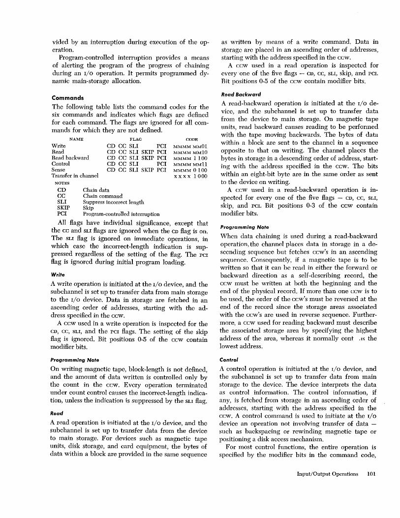
vided by an interruption during execution of the operation.
Program-controlled interruption provides a means of alerting the program of the progress of chaining during an I/O operation. It permits programmed dynamic main-storage allocation.
Commands
The following table lists the command codes for the six commands and indicates which Hags are defined for each command. The Hags are ignored for all commands for which they are not defined.
Write Read
NAME
Read backward Control Sense Transfer in channel
NOTES
FLAG
CD CC SLI PCI CD CC SLI SKIP PCI CD CC SLI SKIP PCI CD CC SLI PCI CD CC SLI SKIP PCI
CD Chain data CC Chain command SLI Suppress incorrect length SKIP Skip PCI Program-controlled interruption
CODE
MMMMMMOI MMMMMM10 MMMM 1100 MMMMMMII MMMM 0100 x x x x 1000
All Hags have individual significance, except that the cc and SLI Hags are ignored when the CD Hag is on. The SLI Hag is ignored on immediate operations, in which case the incorrect-length indication is suppressed regardless of the setting of the Hag. The PCI
Hag is ignored during initial program loading.
Write
A write operation is initiated at the I/O device, and the subchannel is set up to transfer data from main storage to the I/O device. Data in storage are fetched in an ascending order of addresses, starting with the address specified in the ccw.
A ccw used in a write operation is inspected for the CD, CC, SLI, and the PCI Hags. The setting of the skip Hag is ignored. Bit positions 0-5 of the ccw contain modifier bits.
Programming Note
On writing magnetic tape, block-length is not defined, and the amount of data written is controlled only by the count in the ccw. Every operation terminated under count control causes the incorrect-length indication, unless the indication is suppressed by the SLI Hag.
Read
A read operation is initiated at the I/O device, and the subchannel is set up to transfer data from the device to main storage. For devices such as magnetic tape units, disk storage, and card equipment, the bytes of data within a block are provided in the same sequence
as written by means of a write command. Data in storage are placed in an ascending order of addresses, starting with the address specified in the ccw.
A ccw used in a read operation is inspected for every ·one of the five Hags - CD, CC, SLI, skip, and PCI.
Bit positions 0-5 of the ccw contain modifier bits.
Read Backward
A read-backward operation is initiated at the I/O device, and the subchannel is set up to transfer data from the device to main storage. On magnetic tape units, read backward causes reading to be performed with the tape moving backwards. The bytes of data within a block are sent to the channel in a sequence opposite to that on writing. The channel places the bytes in storage in a descending order of address, starting with the address specified in the ccw. The bits within an eight-bit byte are in the same order as sent to the device on writing.
A ccw used in a read-backward operation is inspected for everyone of the five Hags - CD, cc, SLI,
skip, and PCI. Bit positions 0-3 of the ccw contain modifier bits.
Programming Note
When data chaining is used during a read-backward operation, the channel places data in storage in a descending sequence but fetches ccw's in an ascending sequence. Consequently, if a magnetic tape is to be written so that it can be read in either the forward or backward direction as a self-describing record, the ccw must be written at both the beginning and the end of the physical record. If more than one ccw is to be used, the order of the ccw's must be reversed at the end of the record since the storage areas associated with the ccw's are used in reverse sequence. Furthermore, a ccw used for reading backward must describe the associated storage area by specifying the highest address of the area, whereas it normally cont ,IS the lowest address.
Control
A control operation is initiated at the I/O device, and the subchannel is set up to transfer data from main storage to the device. The device interprets the data as control information. The control information, if any, is fetched from storage in an ascending order of addresses, starting with the address specified in the ccw. A control command is used to initiate at the I/O
device an operation not involving transfer of data -such as backspacing or rewinding magnetic tape or positioning a disk access mechanism.
For most control functions, the entire operation is specified by the modifier bits in the command code,
Input/Output Operations 101
and the function is performed over the I/O interface as an immediate operation (see "Immediate Operations" ). If the command code does not specify the entire control function, the data-address field of the ccw designates the required additional information for the operation. This control information may include an order code further specifying the operation to be performed or an address, such as the disk address for the seek function, and is transferred in response to requests by the device.
A control command code containing zeros for the six modifier bits is defined as no operation. The nooperation order causes the addressed device to respond with channel end and device end without causing any action at the device. The order can be executed as an immediate operation, or the device can delay the status until after the initiation sequence is completed. Other operations that can be initiated by means of the control command depend on the type of I/O device. These operations and their codes are specified in the SRL publication for the device.
A ccw used in a control operation is inspected for the CD, CC, SLI, and the PCI Rags. The setting of the skip Rag is ignored. Bit positions 0-5 of the ccw contain modiB.er bits.
Programming Note
Since a count of zero is invalid, the program cannot use the ccw count field to specify that no data be transferred to the I/O device. Any operation terminated before data have been transferred causes the incorrcctlength indication, provided the operation is not immediate and has not been rejected during the initiation sequence. The incorrect-length indication is suppressed when the SLI Rag is on.
Sense
A sense operation is initiated at the I/O device, and the subchannel is set up to transfer data from the device to main storage. The data are placed in storage in an ascending order of addresses, starting with the address specified in the ccw.
Data transferred during a sense operation provide information concerning both unusual conditions detected in the last operation and the status of the device. The status information provided by the sense command is more detailed than that supplied by the unit-status byte and may describe reasons for the unitcheck indication. It may also indicate, for example, if the device is in the not-ready state, if the tape unit is in the file-protected state, or if magnetic tape is positioned beyond the end-of-tape mark.
For most devices, the first six bits of the sense data describe conditions detected during the last opera-
102
tion. These bits are common to all devices having this type of information and are designated as follows:
BIT DESIGNATION
o Command reject 1 Intervention required 2 Bus-out check 3 Equipment check 4 Data check 5 Overrun
The following is the meaning of the first six bits: Command Reject: The device has detected a pro~
gramming error. A command has been received which the device is not designed to execute, such as read issued to a printer, or which the device cannot execute bccause of its present state, such as backspace issued to a tape unit with the tape at load point.
Intervention Required: The last operation could not be executed because of a condition requiring some type of intervention at the device. This bit indicates conditions such as an empty hopper in a card punch or the printer being out of paper. It is also turned on when the addressed device is in the not-ready state, is in test mode, or is not provided on the control unit.
Bus-Out Check: The device or the control unit has received a data byte or a command code with an invalid parity over the I/O interface. During writing, bus-out check indicates that incorrect data have been recorded at the device, but the condition does not cause the operation to be terminated prematurely. Errors on command codes and control information cause the operation to be immediately terminated.
Equipment Check: During the last operation, the device or the control unit has detected equipment malfunctioning, such as an invalid card hole count or printer buffer parity error.
Data Check: The device or the control unit has detected a data error other than those included in busout check. Data check identifies errors associated with thc recording medium and includes conditions such as reading an invalid card code or detecting invalid parit yon data recorded on magnetic tape.
On an input operation, data check indicates that incorrect data may have been placed in main storage. The control unit forces correct parity on data sent to the channel. On writing, this condition indicates that incorrect data may have been recorded at the device. Data errors on reading and writing do not cause the operation to be terminated prematurely.
Overrun: The channel has failed to respond on time to a request for service from the device. Overrun can occur when data are transferred to or from a nonbuffered control unit operating with a synchronous medium, and the total activity initiated by the program exceeds the capability of the channel. When the chan-

nel fails to accept a byte on an input operation, the following data in main storage are shifted to fill the gap. On an output operation, overrun indicates that data recorded at the device may be invalid. The overrun bit is also turned on when the device receives the new command too late during command chaining.
All information significant to the use of the device normally is provided in the first two bytes. Any bit positions following those used for programming information contain diagnostic information, which may extend to as many bytes as needed. The amount and the meaning of the status information are peculiar to the type of I/O device and are specified in the SRL
publication for the device. The sense information pertaining to the last I/O op
eration is reset by the next command, other than sense, addressed to the control unit. The sense command cannot cause the command-reject, interventionrequired, data-check, or overrun bits to be turned on. If the control unit detects an equipment error or invalid parity of the sense command code, the equipment-check or bus-out-check bits are turned on, and unit check is sent with the channel end.
A ccw used in a sense operation is inspected for everyone of the five flags - CD, CC, SLI, skip, and PCI. Bit positions 0-3 of the ccw contain modifier bits.
Transfer In Channel
The next ccw is fetched from the location designated by the data-address field of the ccw specifying trans-
fer in channel. The transfer-in-channel command does not initiate any I/O operation at the channel, and the I/O device is not signaled of the execution of the command. The purpose of the transfer in channel command is to provide chaining between ccw's not located in adjacent double-word locations in an ascending order of addresses. The command can occur in both data and command chaining.
The first ccw designated by the CAW may not specify transfer in channel. When this restriction is violated, no I/O operation is initiated, and the program-check condition is generated. The error causes the status portion of the csw with the program-check indication to be stored during the execution of START I/O.
To address a ccw on integral boundaries for double words, a ccw specifying transfer in channel must contain zeros in bit positions 29-31. Furthermore, a ccw specifying a transfer in channel may not be fetched from a location designated by an immediately preceding transfer in channel. When either of these errors is detected or when an invalid address is specified in transfer in channel, the program-check condition is generated. Detection of these errors during data chaining causes the operation at the I/O device to be terminated, whereas during command chaining they cause an interruption condition to be generated.
The contents of the second half of the ccw, bit positions 32-63, are ignored. Similarly, the contents of bit positions 0-3 of the ccw are ignored.
Input/Output Operations 103
Termination of Input/Output Operations
When the operation or sequence of operations initiated by START I/O is terminated, the channel and the device generate status conditions. These conditions can be brought to the attention of the program by the I/O
interruption mechanism, by TEST I/O, or, in certain cases, by START I/O. The status conditions, as well as an address and a count indicating the extent of the operation sequence, are presented to the program in the form of a csw.
Types of Termination
Normally an I/O operation at the subchannellasts until the device signals channel end. The channel-end condition can be signaled during the sequence initiating the operation, or later. When the channel detects equipment malfunctioning or a system reset is performed, the channel disconnects the device without receiving channel end. The program can force a device on the selector channel to be disconnected prematurely by issuing HALT I/O.
Termination at Operation Initiation
After the addressed channel and subchannel have been verified to be in a state where START I/O can be executed, certain tests are performed on the validity of the information specified by the program and on the availability of the addressed control unit and I/O device. This testing occurs both during the execution of START I/O and during command chaining.
A data-transfer operation is initiated at the subchannel and device only when no programming or equipment errors are detected by the channel and when the device responds with zero status during the initiation sequence. When the channel detects or the device signals any unusual condition during the initiation of an operation, but channel end is off, the command is said to be rejected.
Rejection of the command during the execution of START I/O is indicated by the setting of the condition code in the psw. Unless the device is not operational, the conditions that precluded the initiation are detailed by the portion of the csw stored by START I/O.
The device is not started, no interruption conditions are generated, and the subchannel is not tied up beyond the initiation sequence. The device is immediately available for the initiation of another operation,
104
provided the command was not rejected because of the busy or non-operational condition.
When an unusual condition causes a command to be rejected during initiation of an I/O operation by command chaining, an interruption condition is generated, and the subchannel is not available until the condition is cleared. The not-operational state on command chaining is indicated by means of interface control check; the other conditions are identified by the corresponding status bits in the associated csw. The new operation at the I/O device is not started.
Immediate Operations
Instcad of accepting or rejecting a command, the I/O
device can signal the channel-end condition immediatcly upon receipt of the command code. An I/O operation causing the channel-end condition to be signalcd during the initiation sequence is called an "immediate operation."
When the first ccw designated by the CAW initiates an immediate operation, no interruption condition is generated. If no command chaining occurs, the channel-end condition is brought to the attention of the program by causing START I/O to store the csw status portion, and the subchannel is immediately made available to the program. The I/O operation, however, is initiated, and, if channel-end is not accompanied by device end, the devicc remains busy. Device end, when subsequently provided by the device, causes an interruption condition to be generated.
When command chaining is specified after an immediate operation and no unusual conditions have been detected during the execution, START I/O does not cause storing of csw status. The subsequent commands in the chain are handled normally, and the channel-end condition for the last operation generates an interruption condition even if the device provides the signal immediately upon receipt of the command code.
Whenever immediate completion of an I/O operation is signaled, no data have been transferred to or from the device. The data address in the ccw is not checked for validity, except that it may not exceed the addressing capacity of the model.
Since a count of zero is not valid, any ccw specifying an immediate operation must contain a nonzero count. When an immediate operation is executed, however, incorrect length is not indicated to the program, and command chaining is not suppressed.
Input / Output Interruptions
Input/output interruptions provide a means for the CPU to change its state in response to conditions that occur in I/O devices or channels. These conditions can be caused by the program or by an external event at the device.
Interruption Conditions
The conditions causing requests for I/O interruptions to be initiated are called interruption conditions. An interruption condition can be brought to the attention of the program only once and is cleared when it causes an interruption. Alternatively, an interruption condition can be cleared by TEST I/O, and conditions generated by the I/O device following the termination of the operation at the subchannel can be cleared by START I/O. The latter include the attention, device-end, and control-unit-end conditions, and the channel-end condition when provided by a device on the selector channel after termination of the operation by HALT I/O.
The device initiates a request to the channel for an interruption whenever it detects any of the following conditions:
Channel end Control unit end Device end Attention Unit check Unit exception
When command chaining is specified and is not suppressed because of error conditions, channel end and device end do not cause interruption conditions and are not made available to the program. Unit-check and unit-exception conditions cause interruption to be requested only when the conditions are detected during the initiation of a chained command. Once the command has been accepted by the device, unit check and unit exception do not occur in the absence of channel end, control unit end, or device end.
When the channel detects any of the following conditions, it initiates a request for an I/O interruption without having received the status byte from the device:
PCI flag in a ccw. Execution of HALT I/O on selector channel.
The interruption conditions from the channel can be accompanied by other channel status indications, but none of the device status bits is on when the channel initiates the interruption.
A request for an I/O interruption due to a programcheck condition detected during command chaining (such as invalid command code, count of zero, or two sequential transfer-in-channel commands) may be initiated either by the I/O device or by the channel, de-
pending on the type of channel. To stack the interruption condition in the device, as occurs on the multiplexor channel, the channel signals the device to respond with a unit-status byte consisting of all zeros on a subsequent scan for interruption conditions. The error indication is preserved in the subchannel.
The method of processing a request for interruption due to equipment malfunctioning, as indicated by the presence of the channel-control-check and interfacecontrol-check conditions, depends on the model.
More than one interruption condition can be cleared concurrently. As an example, when the PCI condition exists in the subchannel at the termination of an operation, the PCI condition is indicated with channel end and only one I/O interruption occurs, or only one TEST
I/O is needed. Similarly, if the channel-end condition is not cleared until device end is generated, both conditions may be indicated in the csw and cleared at the device concurrently.
However, at the time the channel assigns highest priority for interruptions to a condition associated with an operation at the subehannel, the channel accepts the status from the device and clears the condition at the device. The interruption condition is subsequently preserved in the snbchannel. Any subsequent status generated by the device is not included with the condition at the suhchannel, even if the status is generated before the CPU accepts the condition.
Priority of Interruptions
All requests for I/O interruption are asynchronous to the activity in the CPU, and interruption conditions associated with more than one I/O device can exist at the same time. The priority among requests is controlled by two types of mechanisms - one establishes the priority among interruption conditions associated with devices attached to the same channel, and another establishes priority among requests from different channels. A channel requests an I/O interruption only after it has established priority among requests from its devices. The conditions responsible for the requests are preserved in the dcvices or channels until accepted by the CPU.
Assignment of priority to requests for interruption associated with devices on anyone channel is a function of the type of interruption condition and the position of the device on the I/O interface cable.
The selector channel assigns the highest priority to conditions associated with the portion of the operation in which the channel is involved. These conditions include channel end, program-controlled interruptions, errors detected or command chaining, and execution of HALT I/O in the channel. The channel cannot handle
Input/Output Operations 105

ceipt of the signal from the device. The channel-end indication in this case is not made available to the program.
Termination by HALT I/O
The instruction HALT r/ a causes the current operation at the addressed channel or subchannel to be terminated immediately. The method of termination differs from that used upon exhaustion of count or upon detection of programming errors to the extent that termination by HALT r/o is not contingent on the receipt of a service request from the device.
When HALT r/o is issued to a channel operating in the burst mode, the channel issues the haIt-r/o signal to the device regardless of the current activity in the channel and on the interface. If the channel is involved in the data-transfer portion of an operation, data transfer is immediately terminated, and the device is disconnected from the channel. If HALT I/O is addressed to a selector channel executing a chain of operations and the device has already provided channel end for the current operation, the instruction causes the device to be disconnected and the chain-command Hag to be removed.
When HALT I/O is issued to the multiplexor channel and the channel is not operating in the burst mode, the haIt-I/o signal is sent to the device whenever the addressed subchannel is in the working state. The subchannel may be transferring data, or it may have already received channel end for the current operation and may be waiting for device end to initiate a new operation by command chaining. In either case, HALT
r/o causes the device to be selected, and the halt-I/o signal is issued as the device responds. When command chaining is indicated in the subchannel, HALT I/O causes the chain-command Hag to be turned off.
Termination of an operation by HALT I/O on the selector channel results in up to four distinct interruption conditions. The first one is generated by the channel upon execution of the instruction and is not contingent on the receipt of status from the device. The command address and count in the associated csw indicate how much data have been transferred, and the channel-status bits reHect the unusual conditions if any, detected during the operation. If HALT r/o i~ issued before all data specified for the operation have been transferred, incorrect length is indicated, subject to the control of the SLI Hag in the current ccw. The execution of HALT I/O itself is not reHected in csw status, and all status bits in a csw due to this interruption condition can be zero. The channel is available for the initiation of a new I/O operation as soon as the interruption condition is cleared.
The second interruption condition on the selector
106
channel occurs when the control unit generates the channel-end condition. The selector channel handles this condition as any other interruption condition from the device with the sub channel available and provides zeros in the protection key, command address, count, and channel status fields of the associated csw. The channel-end condition is not made· available to the program when HALT I/O is issued to a channel executing a chain of operations and the device has already provided channel end for the current operation.
Finally, the third and fourth interruption conditions occur when control unit end, if any, and device end are generated. These conditions are handled as for any other I/O operation.
Termination of an operation by HALT I/O on the multiplexor channel causes the normal interruption conditions to be generated. If the instruction is issued when the subchannel is in the data-transfer portion of an operation, the subchannel remains in the working state until channel end is signaled by the device, at which time the subchannel is placed in the interruption-pending state. If HALT r/o is issued after the device has signaled channel end and the sub channel is executing a chain of operations, the channel-end condition is not made available to the program, and the sub channel remains in the working state until the next status byte from the device is received. Receipt of a status byte subsequently places the sub channel in the interruption-pending state.
The csw associated with the interruption condition in the sub channel contains the status bytes provided by the device and the channel, and indicates at what point data transfer was terminated. If HALT r/o is issued before all data areas associated with the current opcration have been exhausted or filled, incorrect length is indicated, subject to the control of the SLI
Hag in the current ccw. The interruption condition is processed as for any other type of termination.
Termination Due to Equipment Malfunction
When channel equipment malfunctioning is detected or invalid signals are received over the I/O interface, the recovery procedure and the subsequent states of the subchannels and devices on the channel depend on the type of error and on the model. Normally, the program is alerted of the termination by an I/O interruption, and the associated csw indicates the channelcontrol-check or interface-control-check condition. In channels sharing common equipment with the CPU,
malfunctioning detected by the channel may be indicated by a machine-check interruption, in which case no csw is stored. Equipment malfunctioning may cause the channel to perform the malfunction-reset function.

Programming Note
Control operations for which the entire operation is specified in the command code may be executed as immediate operations. Whether the control function is executed as an immediate operation depends on the operation and type of device and is specified in the SRL
publication for the device.
Termination of Data Transfer
When the device accepts a command, the subchannel is set up for data transfer. The subchannel is said to be working during this period. Unless the channel detects equipment malfunctioning or, on the selector channel, the operation is terminated by HALT I/O, the working state lasts until the channel receives the channel-end signal from the device. When no command chaining is specified or when chaining is suppressed because of unusual conditions, the channel-end condition causes the operation at the subchannel to be terminated and an interruption condition to be generated. The status bits in the associated csw indicate channel end and the unusual conditions, if any. The device can signal channel end at any time after initiation of the operation, and the signal may occur before any data have been transferred.
For operations not involving data transfer, the device normally controls the timing of the channel-end condition. The duration of data transfer operations may be variable and may be controlled by the device or the channel.
Excluding equipment errors and HALT I/O, the channel signals the device to terminate data transfer whenever any of the following conditions occurs:
The storage areas specified for the operation are exhausted or filled.
Program-check condition is detected. Protection-check condition is detected. Chaining-check condition is detected.
The first of these conditions occurs when the channel has stepped the count in the last ccw associated with the operation to zero. A count of zero indicates that the channel has transferred all information specified by the program. The other three conditions are due to errors and cause premature termination of data transfer. In either case, the termination is signaled in response to a service request from the device and causes data transfer to cease. If the device has no blocks defined for the operation (such as writing on magnetic tape), it terminates the operation and generates the channel-end condition.
The device can control the duration of an operation and the timing of channel end by blocking of data. On certain operations for which blocks are defined (such as reading on magnetic tape), the device does not
provide the channel-end signal until the end of the block is reached, regardless of whether or not the device has been previously signaled to terminate data transfer.
The channel suppresses initiation of an I/O operation when the data address in the first ccw associated with the operation exceeds the addressing capacity of the model. Complete check for the validity of the data address is performed only as data are transferred to or from main storage. When the initial data address in the ccw is invalid, no data are transferred during the operation, and the device is signaled to terminate the operation in response to the first service request. On writing, devices such as magnetic tape units request the first byte of data before any mechanical motion is started and, if the initial data address is invalid, the operation is terminated before the recording medium has been advanced. However, since the operation has been initiated, the device provides channel end, and an interruption condition is generated. Whether a block at the device is advanced when no data are transferred depends on the type of device and is specified in the SRL publication for the device.
When command chaining takes place, the subchannel appears in the working state from the time the first operation is initiated until the device signals the channel-end condition of the last operation of the chain. On the selector channel, the device executing the operation stays connected to the channel and the whole channel appears to be in the working state for the duration of the execution of the chain of operations. On the multiplexor channel an operation in the burst mode causes the channel to appear to be in the working state only for the duration of the transfer of the burst of data. If channel end and device end do not occur concurrently, the device disconnects from the channel after providing channel end, and the channel can in the meantime communicate with other devices on the interface.
Any unusual conditions cause command chaining to be suppressed and an interruption condition to be generated. The unusual conditions can be detected by either the channel or the device, and the device can provide the indications with channel end, control unit end, or device end. When the channel is aware of the unusual condition by the time the channel-end signal for the operation is received, the chain is terminated as if the operation during which the condition occurred were the last operation of the chain. The device-end signal subsequently is processed as an interruption condition. When the device signals unit check or unit exception with control unit end or device end, the sub channel terminates the working state upon re-
Input/Output Operations 107

any interruption conditions while an operation is in progress.
As soon as the selector channel has cleared the interruption conditions associated with data transfer, it starts scanning devices for attention, control-unit-end, and device-end conditions and for the channel-end condition associated with operations terminated by HALT I/O. The highest priority is assigned to the I/O
device that first identifies itself on the interface. On the multiplexor channel the priority among re
quests for interruption is based only on the response to scanning. The multiplexor channel continuously scans its I/O devices. The highest priority is assigned to the device that first responds with an interruption condition or that requests service for data transfer and contains the PCI condition in the subchannel. The PCI,
as well as any other condition in the subchannel, cannot cause an I/O interruption unless the device initiates a reference to the subchannel.
Except for conditions associated with termination of data transfer, the current assignment of priority for interruption among devices on a channel may be canceled when START I/O or TEST I/O is issued to the channel. Whenever the assignment is canceled, the channel resumes scanning for interruption conditions and reassigns the priority on completion of the activity associated with the I/O instruction.
The assignment of priority among requests for interruption from channels is based on the type of channel. The priorities of selector channels are in the order of their addresses, with channel 1 having the highest priority. The interruption priority of the multiplexor channel is not fixed and depends on the model and on the current activity in the channel. Its priority may be above, below, or between those of the selector channels.
Interruption Action
An I/O interruption can occur only when the channel accommodating the device is not masked and after the execution of the current instruction in the CPU has been terminated. If a channel has established the priority among requests for interruption from devices while it is masked, the interruption occurs immediately after the termination of the instruction removing the mask and before the next instruction is executed. This interruption is associated with the highest priority condition on the channel. If more than one channel is unmasked concurrently, the interruption occurs from the channel having the highest priority among those requesting interruption.
If the priority among interruption conditions has not yet been established in the channel by the time the mask is removed, the interruption does not necessarily
108
occur immediately after the termination of the instruction removing the mask. This delay can occur regardless of how long the interruption condition has existed in the device or the subchannel.
The interruption causes the current program status word (psw) to be stored as the old psw at location 56 and causes the csw associated with the interruption to be stored at location 64. Subsequently, a new psw is loaded from location 120, and processing resumes in the state indicated by this psw. The I/O device causing the interruption is identified by the channel address in bit positions 21-23 and by the device address in bit positions 24-31 of the old psw. The csw associated with the interruption identifies the condition responsible for the interruption and provides further details about the progress of the operation and the status of the device.
Programming Note
When a number of I/O devices on a shared control unit are concurrently executing operations such as rewinding tape or positioning a disk access mechanism, the initial device-end signals generated on completion of the operations are provided in the order of generation, unless command chaining is specified for the operation last initiated. In the latter case, the control unit provides the device-end signal for the last initiated operation first, and the other signals are delayed until the subchannel is freed. Whenever interruptions due to the device-end signals are delayed either because the channel is masked or the subchannel is busy, the original order of the signals is destroyed.
Channel Status Word
The channel status word (csw) provides to the program the status of an I/O device or the conditions under which an I/O operation has been terminated. The csw is formed, or parts of it are replaced, in the process of I/O interruptions and during execution of START I/O, TEST I/O, and HALT I/O. The csw is placed in main storage at location 64 and is available to the program at this location until the time the next I/O interruption occurs or until another I/O instruction causes its content to be replaced, whichever occurs first.
When the csw is stored as a result of an I/O interruption, the I/O device is identified by the I/O address in the old psw. The information placed in the csw by START I/O, TEST I/O, or HALT I/O pertains to the device addressed by the instruction.
The csw has the following format:
I~K_e_Y~I_o_o __ o_o~I __________ C_om_m_a_n_d_A __ dd_r_es_s __ ---------.J 34 7 8 31
L Status Count 4748 63

The fields in the csw are allocated for the following purposes:
Protection Key: Bits 0-3 form the storage protection key used in the chain of operations initiated by the last START I/O.
Command Address: Bits 8-31 form an address that is eight higher than the address of the last ccw used.
Status: Bits 32-47 identify the conditions in the device and the channel that caused the storing of the csw. Bits 32-39 are obtained over the I/O interface and indicate conditions detected by the device or the control unit. Bits 40-47 are provided by the channel and indicate conditions associated with the subchannel. Each of the 16 bits represents one type of condition, as follows:
nIT DESIGNATION BIT DESIGNATION
32 Attention 40 Pro gram -con trolled interruption
33 Status modifier 41 Incorrcct length 34 Control unit end 42 Program check 35 Busy 43 Protection check 36 Channel end 44 Channel data check 37 Device end 45 Channel control check 38 Unit cheek 46 Interface control check 39 Unit exception 47 Chaining check
Count: Bits 48-63 form the residual count for the last ccw used.
Unit Status Conditions
The following conditions are detected by the I/O device or control unit and are indicated to the channel over the I/O interface. The timing and causes of these conditions for each type of device are specified in the SRL publication for the device.
When the I/O device is accessible from more than one subchannel, status is signaled to the sub channel that initiated the associated I/O operation. The handling of conditions not associated with I/O operations depends on the type of device and condition and is specified in the SRL publication for the device.
The channel does not modify the status bits received from the I/O device. These bits appear in the csw as received over the interface.
Attention
Attention is caused upon the generation of the attention signal at the I/O device. The attention signal can be generated at any time and is interpreted by the program. Attention is not associated with the initiation, execution, or termination of any I/O operation.
The attention condition cannot be indicated to the program while an operation is in progress at the I/O
device, control unit, or subchannel. Otherwise, the handling and presentation of the condition to the channel depend on the type of device.
Status Modifier
Status modifier is generated by the device when the normal sequence of commands has to be modified or when the control unit detects during the selection sequence that it cannot execute the command or instruction as specified.
When the status-modifier condition is provided in response to TEST I/O, presence of the bit indicates that the device cannot execute the instruction and that no bits pertaining to the current status of the device have been provided. The status of the device and subchannel is not changed, and the csw stored by TEST I/O
contains zeros in the key, command address, channel status, and count fields. The 2702 Transmission Control is an example of a type of device that cannot execute TEST I/O.
When the status-modifier bit appears in the csw together with the busy bit, it indicates that the busy condition pertains to the control unit associated with the addressed I/O device. The control unit appears busy when it is executing a type of operation or is in a state that precludes the acceptance of any command or the instruction TEST I/O and HALT I/O. This occurs for operations such as backspace tape file, in which case the control unit remains busy after providing channel end, and for operations terminated on the selector channel by HALT I/O. The combination of busy and status modifier can be provided in response to any command as well as TEST I/O and HALT I/O.
Presence of both busy and status modifier in response to TEST I/O is handled the same way as when status modifier alone is on.
Once the execution of a command has been initiated, the status-modifier indication can be provided only together with device end. The handling of this set of bits by the channel depends on the operation. If command chaining is specified in the current ccw and no unusual conditions have been detected, presence of the bit causes the channel to fetch and chain to the ccw whose main-storage address is 16 higher than that of the current ccw. If the I/O device signals the status-modifier condition at a time when the chaincommand flag is off or when any unusual conditions have been detected, no action is taken in the channel, and the status-modifier bit is placed in the csw.
Programming Note
When the multiplexor channel detects a programming error during command chaining, the interruption condition is queued at the I/O device. On devices such as the 2702 Transmission Control, queuing of the condition may generate the status-modifier indication, which subsequently appears in the csw associated with the termination of the operation.
Input/Output Operations 109
Control Unit End
Control unit end indicates that the control unit has become available for use for another operation.
The control-unit-end condition is provided only by control units shared by I/O devices and only when one or both of the following conditions has occurred:
1. The program has caused the control unit to be interrogated while the control unit was executing an operation. The control unit is considered to have been interrogated when START I/O, TEST I/O, or HALT I/O
has been issued to a device on the control unit, and the control unit had responded with busy and status modifier in the unit status byte. START I/O and TEST
I/O cause interrogation of the control unit when the control unit is still executing a previously initiated operation, but the sub channel is available or, for TEST
I/O, the subchannel on the multiplexor channel contains an interruption condition for the addressed device. The instruction HALT I/O can cause the control unit to be interrogated when issued to a device sharing a control unit and operating in the multiplex mode.
2. The control unit detected an unusual condition during the portion of the operation after channel end had been signaled to the channel.
If the control unit remains busy with the execution of an operation after signaling channel end but has not been interrogated by the program, control unit end is not generated. Similarly, control unit end is not provided when the control unit has been interrogated and could perform the indicated function. The latter case is indicated by the absence of busy and status modifier in the response to the instruction causing the interrogation.
When the busy state of the control unit is temporary, control unit end is included with busy and status modifier in response to the interrogation even though the control unit has not yet been freed. The busy condition is considered to be temporary if its duration is short with respect to the program time required to handle an I/O interruption. The 2702 Transmission Control is an example of a device in which the control unit may be busy temporarily and which includes control unit end with busy and status modifier.
The device address associated with control unit end depends on the type of I/O device. The address can be fixed for the control unit, may identify the device on which the terminated operation was executed, or may be the device address specified in the instruction causing the control unit to be interrogated.
The control-unit-end condition can be signaled with channel end, device end, or between the two. A pend-
110
ing control unit end causes the control unit to appear busy for initiation of new operations.
Busy
Busy indicates that the I/O device or control unit cannot execute the command or instruction because it is executing a previously initiated operation or because it contains an interruption condition. The interruption condition for the addressed device, if any, accompanies the busy indication. If the busy condition applies to the control unit, busy is accompanied by status modifier.
The following table lists the conditions when the busy bit (B) appears in the csw and when it :is accompanied by the status-modifier bit (SM). A double hyphen (--) indicates that the busy bit is off; an asterisk (~) indicates that csw status is not stored or an I/O interruption cannot occur; and the (cl) indicates that the interruption condition is cleared and the status appears in the csw. The abbreviation DE
stands for device end, while cu stands for control unit.
CONDITION
Subchannel available DE or attention in device Device working, CU available CU end or channel end in CU:
for the addressed device for another device
CU working Interruption pend. in subchannel
for the addressed device because of:
chaining terminated by attention
other type of termination Subchannel working
CSW STATUS STORED BY:
START TEST HALT I/O
I/O I/O I/O INT.
B,cl B
B,cl B,SM B,SM
--,cl B
--,cl B,SM B,SM
,cl --,cl
--,cl ~
--,cl --,cl ~
B,cl --,cl
CU available ~ ~ ~
CU working ~ ~ B,SM ~
The busy bit is included in the status associated with a pending interruption condition from the subchannel only when a chain of commands has been prematurely terminated because of attention and no interruption was pending in the channel at the time of chaining.
Channel End
Channel end is caused by the completion of the portion of an I/O operation involving transfer of data or control information between the I/O device and the channel. The condition indicates that the sub channel has become available for use for another operation.
Each I/O operation causes a channel-end condition to be gencrated, and there is only one channel end for an operation. When command chaining takes place, only the channel end of the last operation of the chain is made available to the program. The channel-end
condition, however, is not made available to the program when a chain of commands is prematurely terminated because of an unusual condition indicated with control unit end or device end. The channel-end condition is not generated when programming or equipment errors are detected during initiation of the operation.
The instant within an I/O operation when channel end is generated depends on the operation and the type of device. For operations such as writing on magnetic tape, the channel-end condition occurs when the block has been written. On devices that verify the writing, channel end mayor may not be delayed until verification is performed, depending on the device. When magnetic tape is being read, the channel-end condition occurs when the gap on tape reaches the read-write head. On devices equipped with buffers, such as a line printer, the channel-end condition occurs upon completion of data transfer between the channel and the buffer. During control operations, channel end is generated when the control information has been transferred to the devices, although for short operations the condition may be delayed until completion of the operation. Operations that do not cause any data to be transferred can provide the channelend condition during the initiation sequence.
A channel-end condition pending in the control unit causes the control unit to appear busy for initiation of new operations. Unless the operation has been performed on the selector channel and has been terminated by HALT I/O, channel end causes the subchannel to be in the interruption-pending state.
Device End
Device end is caused by the completion of an I/O operation at the device or, on some devices, by manually changing the device from the not-ready to the ready state. The condition indicates that the I/O device has become available for use for another operation.
Each I/O operation causes a device-end condition, and there is only one device end to an operation. When command chaining takes place, only the device end of the last operation of the chain is made available to the program. The device-end condition is not generated when any programming or equipment errors are detected during initiation of the operation.
The device-end condition associated with an I/O
operation is generated either simultaneously with the channel-end condition or later. On data transfer operations on devices such as magnetic tape units, the device terminates the operation at the time channel end is generated, and both device end and channel end occur together. On buffered devices, such as a line printer, the device-end condition occurs upon
completion of the mechanical operation. For control operations, device end is generated at the completion of the operation at the device. The operation may be completed at the time channel end is generated or later.
When command chaining in the current ccw is specified, receipt of the device-end signal, in the absence of any unusual conditions, causes the channel to initiate a new I/O operation.
Unit Check
Unit check is caused by any programming or equipment errors detected by the I/O device or control unit. The errors responsible for the unit check are detailed by the information available to a sense command. The unit-check bit provides a summary indication of the errors identified by sense data.
The unit-check condition is generated only when the error is detected during the execution of TEST I/O
or a command. The device does not alert the program of any equipment malfunction occurring at a time when the device is not executing an operation and does not have a pending interruption condition. Malfunctioning detected at this time may cause the device to become not ready; unit check in this case is signaled to the program the next time the device is selected.
If the device detects during the initiation sequence that the command cannot be executed, unit check is presented to the channel and appears in the csw without channel end, control unit end, or device end. Such unit status indicates that no action has been taken at the device in response to the command. If the condition precluding proper execution of the operation occurs after execution has been started, unit check is accompanied by channel end, control unit end, or device end, depending on when the condition was detected.
Termination of an operation with the unit-check indication causes command chaining to be suppressed.
Unit Exception
Unit exception is caused when the I/O device detects a condition that usually does not occur. The condition includes conditions such as recognition of a tape mark and does not necessarily indicate an error. It has only one meaning for any particular command and type of device.
The unit-exception condition can be generated only when the device is executing an I/O operation. If the device detects during the initiation sequence that the operation cannot be executed, unit exception is presented to the channel and appears in the csw without
Input/Output Operations III

channel end, control end, or device end. Such unit status indicates that no action has bcen taken at the device in response to the command. If the condition precluding normal execution of the operation occurs after the execution has been started, unit exception is accompanied by channel end, control unit end, or device end, depending on when the condition was detected.
Termination of an operation with the unit-exception indication causes command chaining to be suppressed.
Channel Status Conditions
The following conditions are detected and indicated by the channel. Except for the conditions caused by equipment ma1functioning, they can occur only while the subchannel is involved with the execution of an I/O
operation.
Program-Controlled Interruption
The program-controlled-interruption condition is generated when the channel fetches a ccw with the program-controlled-interruption (PCI) flag on. The interruption due to the PC! flag takes place as soon as possible after fetching the ccw but may be delayed an unpredictable amount of time because of masking of the channel or other activity in the system.
Detection of the PCI condition does not affect the progress of the I/O operation.
Incorrect Length
Incorrect length occurs when the number of bytes contained in the storage areas assigned for the I/O operation is not equal to the number of bytes requested or offered by the I/O device. Incorrect length is indicated for one of the following reasons:
l.Jong blocl( on Input: During a read, read-backward, or sense operation, the device attempted to transfer one or more bytes to storage after the assigned storage areas were filled. The extra bytes have not been placed in main storage. The count in the csw is zero.
IJong Block on Output: During a write or control operation the device requested one or more bytes from the channel after the assigned main-storage areas were exhausted. The count in the csw is zero.
Short Block on Input: The number of bytes transferred during a read, read hackward, or sense operation is insufficient to fill the storage areas assigned to the operation. The count in the csw is not zero.
Short Block on Output: The device terminated a write or control operation before all information contained in the assigned storage areas was transferred to the device. The count in the csw is not zero.
The incorrect-length indication is suppressed when
112
the current ccw has the SLI flag and does not have the CD flag. The indication does not occur for immediate operations and for operations rejected during the initiation sequence.
Presence of the incorrect-length condition suppresses command chaining unless the SLI flag in the ccw is on or unless the condition occurs in an immediate operation.
The following table lists the effect of the incorrectlength condition for all combinations of the CD, CC,
and SLI flags. It indicates for the two types of operations when the operation at the sub channel is terminated (stop) and when the command chaining takes place. The entry "incorrect length" (IL) means that the indication is made available to the program; a double hyphen (--) means that the indication is suppressed. For all entries, the current operation is assumed to have caused the incorrect-length condition.
FLAGS ACTION AND INDICATION
CD CC SLI HEGULAB OPEBA TION IMMEDIATE OPEHATION
0 0 0 Stop,IL Stop, --0 0 1 Stop, -- Stop, --0 1 0 Stop,IL Chain command 0 1 1 Chain command Chain command 1 0 0 Stop,IL Stop, --I 0 1 Stop,IL Stop, --I 1 0 Stop,IL Stop, --I 1 1 Stop,IL Stop, --
Program Check
Program check occurs when programming errors are detected hy the channel. The condition can be due to the following causes:
Invalid C CW Address Specification: The CAW or the transfer-in-channel command does not designate the ccw on integral boundaries for double words. The three low-order bits of the ccw address are not zero.
Invalid CCW Address: The channel has attempted to fetch a ccw from a location outside the main storage of the particular installation. An invalid ccw address can occur in the channel because the program has specified an invalid address in the CAW or in the transfer-in-channel command or because on chaining the channel has stepped the address above the highest available location.
Invalid Command Code: The command code in the first ccw designated by the CAW or in a ccw fetched on command chaining has four low-order zeros. The command code is not tested for validity during data chaining.
Invalid Count: A ccw other than a ccw specifying transfer in channel contains the value zero in bit positions 48-63.
Invalid Data Address: The channel has attempted to transfer data to or from a location outside the main storage of the particular installation. An invalid data

address can occur in the channel because the program has specified an invalid address in the ccw or because the channel has stepped the address above the highest available address or, on reading backward, below zero.
Invalid Key: The CAW contains a nonzero storage protection key in a model not having the protection feature installed.
Invalid CAW Format: The CAW does not contain zeros in bit positions 4-7.
Invalid CCW Format: A ccw other than a ccw specifying transfer in channel does not contain zeros in hit positions 37-39.
Invalid Sequence: The first ccw designated by the CAW specifies transfer in channel or the channel has fetched two successive ccw's both of which specify transfer in channel.
Detection of the program-check condition during the initiation of an operation causes execution of the operation to be suppressed. When the condition is detected after the device has been started, the device is signaled to terminate the operation. The programcheck condition causes command chaining to be suppressed.
Protection Check
Protection check occurs when the channel attempts to place data in a portion of main storage that is protected for the current operation on the subchannel. The protection key associated with the I/O operation does not match the key of the addressed main-storage location, and neither of the keys is zero.
Detection of the protection-check condition causes the device to be signaled to terminate the operation; command chaining is suppressed.
The protection-check condition can be generated only on models having the protection feature installed.
Channel Data Check
Channel data check is caused by data errors detected in the channel or in main storage. The condition covers all data transferred to or from an I/O device, including sense and control information. It includes any parity errors detected on I/O data in main storage, in the channel, or as received from the device over the I/O
interface. The channel attempts to force correct parity on data
placed in main storage. On output operations, the parity of data sent to the device is not changed.
Parity errors on data cause command chaining to be suppressed and, depending on model, may cause the current operation to be terminated. When the channel and the CPU share common equipment, parity errors on data may cause malfunction reset to be performed. The
recovery procedure in the channel and the subsequent state of the subchannel upon a malfunction reset depend on the model.
Channel Control Check
Channel control check is caused by any machine malfunctioning affecting channel controls. The condition includes parity errors on ccw and data addresses and parity errors on the contents of the ccw. Conditions responsible for channel control check usually cause the contents of the csw to be invalid and conflicting.
The csw as generated by the channel has correct parity. The channel either forces correct parity on the csw fields or sets the invalid fields to zero.
Detection of the channel-control-check condition causes the current operation, if any, to be immediately terminated and may cause the channel to perform the malfunction-reset function. The recovery procedure in the channel and the subsequent state of the subchannel upon a malfunction reset depend upon the model.
Interface Control Check
Interface control check is caused by any invalid signal on the I/O interface. The condition is detected by the channel and usually indicates malfunctioning of an I/O
device. It can be due to the following reasons: 1. The address or status byte received from a de
vice has invalid parity. 2. A device responded with an address other than
the address specified by the channel during initiation of an operation.
3. During command chaining the device appeared not operational or indicated the busy condition without providing any other status bits.
4. A signal from a device occurred at an invalid time or had invalid duration. Detection· of the interface-control-check condition
causes the current operation, if any, to be immediately terminated and may cause the channel to perform the maHunction-reset function. The recovery procedure in the channel and the subsequent state of the subchannel upon a malfunction reset depends on the model.
Chaining Check
Chaining check is caused by channel overrun during data chaining on input operations. The condition occurs when the I/O data rate is too high for the particular resolution of data addresses. Chaining check cannot occur on output operations.
Detection of the chaining-check condition causes the 110 device to be signaled to terminate the operation. It causes command chaining to be suppressed.
Input/Output Operations 113
Content of Channel Status Word
The content of the csw depends on the condition causing the storing of the csw and on the programming method by which the information is obtained. The status portion always identifies the condition that caused storing of the csw. The protection key, command address, and count fields may contain information pertaining to the last operation or may be set to zero, or the original contents of these fields at location 64 may be left unchanged.
Information Provided by Channel Status Word
Conditions associated with the execution or termination of an operation at the subchannel cause the whole csw to be replaced.
Such a csw can be stored only by an I/O interruption or by TEST I/O. Except for conditions associated with command chaining, the storing can be caused by the PCI or channel-end condition, by the execution of HALT I/O on the selector channel, or by equipment malfunction. The contents of the csw are related to the current values of the corresponding quantities, although the count is unpredictable after programming errors and after an interruption due to the PCI flag.
A csw stored upon the execution of a chain of operation pertains to the last operation the channel executed or attempted to initiate. Information concerning the preceding operations is not preserved and is not made available to the program.
When an unusual condition causes command chaining to be suppressed, the premature termination of the chain is not explicitly indicated in the csw. A csw associated with a termination due to a condition occuring at channel-end time contains the channel-end bit and identifies the unusual condition. When the device signals the unusual condition with control unit end or device end, the channel-end indication is not made available to the program, and the channel provides the current protection key, command address, and count, as well as the unusual indication, with the controlunit-end or device-end bit in the csw. The command address and count fields pertain to the operation that was executed.
When the execution of a chain of commands is terminated by an error detected during initiation of a new operation, the command address and count fields pertain to the rejected command. Termination at initiation time can occur because of attention, unit check, unit exception, program check, or equipment malfunctioning and causes both the channel-end and device-end bits in the csw to be off.
114
A csw associated with conditions occurring after the opcration at the subchannel has been terminated contains zeros in the protection key, command address, and count fields, provided the conditions are not cleared by START I/O. These conditions include attention, control unit end, and device end (and channel end when it occurs after termination of an operation on the selector channel by HALT I/O).
When the above conditions are cleared by START I/O,
only the status portion of the csw is stored, and the original contents of the protection key, command address, and count fields in location 64 are preserved. Similarly, only the status bits of the csw are changed when the command is rejected or the operation at the subchannel is terminated during the execution of START
I/O or whenever HALT I/O causes csw status to be stored.
Errors detected during execution of the I/O operation do not affect the validity of the csw unless the channel-control-check or interface-control-check conditions are indicated. Channel control check indicates that equipment errors have been detected, which can cause any part of the csw, as well as the address in the psw identifying the I/O device, to be invalid. Interface control check indicates that the address identifying the device or the status bits received from the device may he invalid. The channel forces correct parity on invalid csw fields.
Protection Key
A csw stored to reflect the progress of an operation at the su bchannel contains the protection key used in that operation. The content of this field is not affected by programming errors detected by the channel or by the condition causing termination of the operation.
Models in which the protection feature is not implemented cause an all-zero key to be stored.
Command Address
When the csw is formed to reflect the progress of the I/O operation at the subchannel, the command address is normally eight higher than the address of the last ccw used in the operation.
The following table lists the contents of the command address field for all conditions that can cause the csw to be stored. The conditions are listed in order of priority; that is, if two conditions are indicated or occur, the csw appears as indicated for the condition higher on the list. The programming errors listed in the table refer to conditions included in program check.
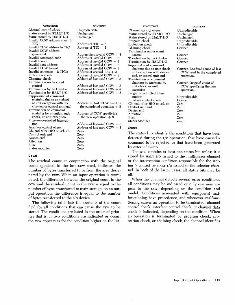
CONDITION
Channel control check Status stored by START I/O Status stored by HALT I/O Invalid CCW address spec. in
TIC Invalid CCW address in TIC Invalid CCW address
generated Invalid command code Invalid count Invalid data address Invalid CCW format Invalid sequence - 2 TIC's Protection check Chaining check Termination under count
control Termination by I/O device Termination by HALT I/O Suppression of command
chaining due to unit check or unit exception with device end or control unit end
Termination on command chaining by attention, unit check, or unit exception
Program-controlled interrup-tion
Interface control check Ch. end after HIO on seI. ch. Control unit end Device end Attention Busy Status modifier
Count
CONTENT
Unpredictable Unchanged Unchanged
Address of TIC + 8 Address of TIC + 8
Address first invalid CCW + 8 Address of invalid CCW + 8 Address of invalid CCW + 8 Address of invalid CCW + 8 Address of invalid CCW + 8 Address of second TIC + 8 Address of invalid CCW + 8 Address of last-used CCW + 8
Address of last-used CCW + 8 Address of last-used CCW + 8 Address of last-used CCW + 8
Address of last CCW used in the completed operation + 8
Address of CCW specifying the new operation + 8
Address of last-used CCW + 8 Address of last-used CCW + 8 Zero Zero Zero Zero Zero Zero
The residual count, in conjunction with the original count specified in the last ccw used, indicates the number of bytes transferred to or from the area designated by the ccw. When an input operation is terminated, the difference between the original count in the ccw and the residual count in the csw is equal to the number of bytes transferred to main storage; on an output operation, the difference is equal to the number of bytes transferred to the I/O device.
The following table lists the contents of the count field for all conditions that can cause the csw to be stored. The conditions are listed in the order of priority; that is, if two conditions are indicated or occur, the csw appears as for the condition higher on the list.
CONDITION
Channel control check Status stored by START I/O Status stored by HALT I/O Program check Protection check Chaining check Termination under count
control Termination by I/O device Termination by HALT I/O Suppression of command
chaining due to unit check, unit exception with device end, or control unit end
Termination on command chaining by atention, by unit check, or unit exception
Program-controlled inter-ruption
Interface control check Ch. end after HIO on sel. ch. Control unit end Device end Attention Busy Status Modifier
Status
CONTENT
Unpredictable Unchanged Unchanged Unpredictable Unpredictable Correct
Correct Correct Correct
Correct. Residual count of last CCW used in the completed operation.
Correct. Original count of CCW specifying the new operation.
Unpredictable Correct Zero Zero Zero Zero Zero Zero
The status bits identify the conditions that have been detected during the I/O operation, that have caused a command to be rejected, or that have been generated by external events.
The csw contains at least one status bit, unless it is stored by HALT I/O issued to the multiplexor channel or the interruption condition responsible for the storing is caused by HALT r/o issued to the selector channel. In both of the latter cases, all status bits may be off.
When the channel detects several error conditions, all conditions may be indicated or only one may appear in the csw, depending on the condition and model. Conditions associated with equipment malfU'hctioning have precedence, and whenever maHunctioning causes an operation to be terminated, channel control check, interface control check, or channel data check is indicated, depending on the condition. When an operation is terminated by program check, protection check, or chaining check, the channel identifies
Input/Output Operations 115

the condition responsible for the termination and may or may not indicate incorrect length. When a data error has been detected before termination due to program check, protection check, or chaining check, both data check and the programming error are identified.
If the csw fetched on command chaining contains the PCI flag but a programming error in the contents of the csw or an unusual condition signaled by the device precludes the initiation of the operation, the PCI
bit appears in the csw associated with the interruption condition. Similarly, if device status or a programming error in the contents of the ccw causes the command
to be rejected during execution of START I/O, the csw stored by START I/O contains the PCI flag. The I/O flag, however, is not included in the csw if a programming error in the contents of the CAW prevents the operation from being initiated.
Conditions detected by the channel are not related to those identified by the I/O device.
The following table summarizes the handling of status bits. The table lists the states and activities that can cause status indications to be created and the methods by which these indications can be placed in the csw.
TIME AND METHOD OF CREATING AND STORING STATUS INDICATIONS
WHEN WHEN UPON TERMINATION OF OPERATION DURING BY BY BY BY I/O
I/O IS SUB CHANNEL AT AT CONTROL AT COMMAND START TEST HALT INTER-
STATUS IDLE WORKING SUBCIIANNEL UNIT DEVICE CHAINING I/O I/O I/O RUPTION ----------
Attention Co Status modifier Control unit end Busy Channel end Co Device end Co Unit check C Unit exception C
Program-controlled interruption Co C
Incorrect length C C Program check C C Protection check C C Channel data check Co C Channel control check Co Co Co Interface control check Co Co Co Chaining check C C
NOTES
C-The channel or the device can create or present the status condition at the indicated time. A CSW or its status portion is not necessarily stored at this time.
Condition such as channel end and device end are created at the indicated time. Other conditions may have been created previously, but are made accessible to the program only at the indicated time. Examples of such conditions are program check and channel data check, which are detected while data are transferred, but are made available to the program only with channel end, unless the PCI flag or equipment malfunctioning have caused an interruption condition to be generated earlier.
S-The status indication is stored in the CSW at the indicated time.
An S appearing alone indicates that the condition has been created previously. The letter C appearing with the S indicates that the status condition did not necessarily exist previously in the form that causes the program to be alerted, and may have
116
C Co S S S C C CS CS CS S
C1) CS CS CS S C CS CS CS S
C1)H COt Ct S S S Co C l' C1' S s S
C C Co CS CS CS C C Co CS S S
C CS S S
S S Co CS S S
S S S S
C1) Co Co CS CS CS CS C1) Co Co Cs CS Cs CS
S S
been created by the I/O instruction or I/O interruption. For example, equipment malfunctioning may be detected during an I/O interruption, causing channel control check or interface control check to be indicated; or a device such as the 2702 Transmission Control Unit may signal the control-un it-busy condition in response to interrogation by an I/O instruction, causing status modifier, busy, and control unit end to be indicated in the CSW.
1) -The status condition generates or, in the case of channel data check, may generate an interruption condition.
Channel end and device end do not result in interruption conditions when command chaining is specified and no unusual conditions have becn detected.
1'-This status indication can be created at the indicated time only by an immediate operation.
II-When an operation on the selector channel has been terminatcd by HALT I/O, channel end indicates the termination of thc datu-hundling portion of the operation at the control unit.
The system control panel contains the switches and lights necessary to operate and control the system. The system consists of the CPU, storage, channels, online control units, and I/O devices. Off-line control units and I/O devices, although part of the system environment, are not considered part of the system proper.
System controls are divided into three sections: operator control, operator intervention, and customer engineering control. Customer engineering controls are also available on some storage, channel, and control-unit frames.
No provision is made for locking out any section of the system control panel. The conditions under which individual controls are active are described for each case.
System Control Functions The system-reset function resets the CPU, the channels, panel are the ability to reset the system; to store and display information in storage, in registers and in the PSW; and to load initial program information.
System Reset
The system-reset function resets the CPU, the channels, and on-line, nonshared control units and I/O devices.
The CPU is placed in the stopped state and all pending interruptions are eliminated. The parity of general and floating-point registers, as well as the parity of the PSW, may be corrected. All error-status indicators are reset to zero.
In general, the system is placed in such a state that processing can be initiated without the occurrence of machine checks, except those caused by subsequent machine malfunction.
The reset state for a control unit or device is described in the appropriate System Reference Library (SRL) publication. Off-line control units are not reset. A system-reset signal from a CPU resets only the functions in a shared control unit or device belonging to that CPU. Any function pertaining to another CPU
remains undisturbed. The system-reset function is performed when the
system-reset key is pressed, when initial program
System Control Panel
loading is initiated, or when a power-on sequence is performed.
Programming Notes
Because the system reset may occur in the middle of an operation, the contents of the psw and of result registers or storage locations are unpredictable. If the CPU is in the wait state when the system reset is performed, and I/O is not operating this uncertainty is eliminated.
Following a system reset, incorrect parity may exist in storage in all models and in the registers in some models. Since a machine check occurs when information with incorrect parity is used, the incorrect information should be replaced by loading new information.
Store and Display
The store-and-display function permits manual intervention in the progress of a program. The store-anddisplay function may be prOVided by a supervisor program in conjunction with proper I/O equipment and the interrupt key.
In the absence of an appropriate supervisor program, the controls on the operator intervention panel permit the CPU to be placed in the stopped state and subsequently to store and display information in main storage, in general and floating-point registers, and in the instruction-address part of the psw. The stopped state is achieved at the end of the current instruction when the stop key is pressed, when single instruction execution is specified, or when a preset address is reached. Once the desired intervention is completed, the CPU can be started again.
All basic store-and-display functions can be simulated by a supervisor program. The stopping and starting of the CPU in itself does not cause any alteration in program execution other than the time element involved (the transition from operating to stopped state is described under "Stopped State" in "Status-Switching").
Interruption checks occurring during store-and-display functions do not interrupt or log immediately but may, in some cases, create a pending interruption. This interruption request can be removed by a system reset. Otherwise, the interruption, when not masked off, is taken when the CPU is again in the operating state.
System Control Panel 117

Initial Program Loading
Initial program loading (IPL) is provided for the initiation of processing when the contents of storage or the psw are not suitable for further processing.
Initial program loading is initiated manually by selecting an input device with the load-unit switches and subsequently pressing the load key. When the multisystem feature is installed, initial program loading may be initiated electronically by a signal received on one of the IPL in-lines.
Depressing the load key causes a system reset, turns on the load light, turns off the manual light, sets the prefix trigger (if present), and subsequently initiates a read operation from the selected input device. When reading is completed satisfactorily, a new psw is obtained, the CPU starts operating, and the load light is turned off.
When a signal is received on one of the IPL in-lines, the same sequence of events takes place, except that the read operation is omitted.
System reset suspends all instruction processing, interruptions, and timer updating and also resets all channels, on-line nonshared control units, and I/O devices. The contents of general and floating-point registers remain unchanged, except that the reset procedure may introduce correct parity.
The prefix trigger is set after system reset. In manually initiated IPL, the trigger is set according to the state of the prefix-select key switch. When IPL is initiated by a signal on one of the two IPL in-lines, the trigger is set according to the identity of each line. The prefix trigger is part of the multisystem feature.
If IPL is initiated manually, the select input device starts reading. The first 24 bytes read are placed in storage locations 0-23. Storage protection, program-controlled interruption, and a possible incorrect length indication are ignored. The double-word read into location 8 is used as the channel command word (ccw) for a subsequent input command. When chaining is specified in this ccw, the operation proceeds with the ccw in location 16.
After the input operation is performed, the I/O address is stored in bits 21-31 of the first word in storage. Bits 16-20 are made zero. Bits 0-15 remain unchanged. The input operation and the storing of the I/O address are not performed when IPL is initiated by means of the IPL in-lines.
The CPU subsequently fetches the double word in location 0 as a new psw and proceeds under control of the new psw. The load light is turned off. When the
118
I/O operations and psw loading are not completed satisfactorily, the CPU stops, and the load light remains on.
Programming Notes
Initial program loading resembles a START I/O that specifies the I/O device selected in the loa d -u nit switches and a zero protection key. The ccw for this START I/O has a read command, zero data address, a byte count of 24, command-chain flag on, suppresslength-indication flag on, program-controlled-interruption flag off, and a virtual command address of zero.
Initial program loading reads new information into the first six words of storage. Since the remainder of the IPL program may be placed in any desired section of storage, it is possible to preserve such areas of storage as the timer and psw locations, which may be helpful in program debugging.
If the selected input device is a disk, the IPL information is read from track O.
The selected input device may be the channel-tochannel adapter involving two cpu's. A system reset on this adapter causes an attention signal to be sent to the addressed CPU. That CPU then should issue the write command necessary to load a program into main storage of the requesting CPU.
When the psw in location 0 has bit 14 set to one, the CPU is in the wait state after the IPL procedure (the manual, the system, and the load lights are off, and the wait light is on). Interruptions that become pending during IPL are taken before instruction execution.
Operator Control Section This section of the system control panel contains only the controls required by the operator when the CPU
is operating under full supervisor control. Under supervisor control, a minimum of direct manual intervention is required since the supervisor performs operations like store and display.
The main functions provided by the operator control section are the control and indication of power, the indication of system status, operator to machine communication, and initial program loading.
The operator control section, with the exception of the emergency pull switch, may be duplicated once as a remote panel on a console.
The following table lists all operator controls by the names on the panel or controls and describes them.

NAME
Emergency Pull Power On Power Off Interrupt Wait Manual System Test Load Load Unit Load Prefix Select\)
(I< Multisystem feature
Emergency Pull Switch
IMPLEMENTATION
Pull switch Key, backlighted Key Key Light Light Light Light Light Three rotary switches Key Key switch
Pulling this switch turns off all power beyond the power-entry terminal on every unit that is part of the system or that can be switched onto the system. Therefore, the switch controls the system proper and all off-line and shared control units and 110 devices.
The switch latches in the out position and can be restored to its in position by maintenance personnel only.
When the emergency pull switch is in the out position, the power-on key is ineffective.
Power-On Key This key is pressed to initiate the power-on sequence of the system.
As part of the power-on sequence, a system reset is performed in such a way that the system performs no instructions or 110 operations until explicitly directed. the contents of main storage, including its protection keys, remain preserved.
The power-on key is backlighted to indicate when the power-on sequence is completed. The key is effective only when the emergency pull switch is in its in position.
Power-Off Key
The power-off key is pressed to initiate the power-off sequence of the system.
The contents of main storage and its protection keys are preserved.
Interrupt Key
The interrupt key is pressed to request an external interruption.
The interruption is taken when not masked off and when the CPU is not stopped. Otherwise, the interruption request remains pending. Bit 25 in the interruption-code portion of the current psw is made one to indicate that the interrupt key is the source of the external interruption.
Wait Light
The wait light is on when the CPU is in the wait state.
Manual Light
The manual light is on when the CPU is in the stopped state. Several of the manual controls are effective only when the CPU is stopped, that is, when the manual light is on.
System Light
The system light is on when the CPU cluster meter or customer-engineering meter is running.
Programming Note
The states indicated by the wait and manual lights are independent of each other; however, the state of the system light is not independent of the state of these two lights because of the definition of the running condition for the meters. The following table shows possible conditions.
SYSTEM MANUAL WAIT CPU I/O
LIGHT LIGHT LIGHT STATE STATE
off off off Not allowed when power is on off off on Waiting Not operating off on off Stopped Not operating off on on Stopped, Not operating
waiting on off off Running Undetermined on off on Waiting Operating on on off Stopped Operating on on on Stopped, Operating
waiting
Test Light
The test light is on when a manual control is not in its normal position or when a maintenance function is being performed for CPU, channels, or storage.
Any abnormal switch setting on the system control panel or on any separate maintenance panel for the CPU, storage, or channels that can affect the normal operation of a program causes the test light to be on.
The test light may be on when one or more diagnostic functions under control of DIAGNOSE are activated or when certain abnormal circuit breaker or thermal conditions occur.
The test light does not reflect the state of marginal voltage controls.
Load Light
The load light is on during initial program loading; it is turned on when the load key is pressed and is turned off after the loading of the new psw is completed successfully.
Load-Unit Switches
Three rotary switches provide the II-bit address of the device to be used for initial program loading.
System Control Panel 119
The leftmost rotary switch has eight positions labeled 0-7. The other two are 16-position rotary switches labeled with the hexadecimal characters 0-9, A-F.
Load Key
The load key is pressed to start initial program loading, and is effective while power is on the system.
Prefix-Select Key Switch
The prefix-select key switch provides the choice between main prefix and alternate prefix during manually initiated initial program loading.
The setting of the switch determines the state of the prefix trigger following the system reset after the load key is pressed.
The switch is part of the multisystem feature.
Operato,' Intervention Section This section of the system control panel contains the controls required for the operator to intervene in normal programming operation. These controls may be intermixed with the customer engineering controls, and additional switch positions and nomenclature may be included, depending on the model.
Operator intervention provides the system-reset and the store-and-display functions. Compatibility in performing these functions is maintained, except that the word size used for store and display depends on the physical word size of storage for the model. Switches for display of the instruction address are absent on models that continuously display the instruction address.
The following table lists all intervention controls by the names on the panel or controls and describes them.
NAME
System Reset Stop Rate Start Storage Select Address Data Store Display Set IC Address Compare Alterna te Prefix ~
~ Multisystem feature
System-Re!;et Key
IMPLEMENT A TI ON
Key Key Rotary switch Key Rotary or key switch Rotary or key switches Rotary or key switches Key Key Key Rotary or key switches Light
The system-reset key is pressed to cause a system reset; it is effective while power is on the system. The reset function does not affect any off-line or shared device.
120
Stop Key
The stop key is pressed to cause the CPU to enter the stopped state; it is effective while power is on the system.
Programming Note
Pressing the stop key has no effect when a continuous string of interruptions is performed or when the CPU
is unable to complete an instruction because of machine malfunction. The effect of pressing the key is indicated by the turn-on of the manual light as the CPU enters the stopped state.
Rate Switch
This rotary switch indicates the way in which instructions are to be performed.
The switch has two or more positions, depending on model. The vertical position is marked PROCESS. In this position, the system starts operating at normal speed whcn the start key is pressed. The position left of vertical is marked INSTRUCTION STEP. When the start key is pressed with the rate switch in this position, one complete instruction is performed, and all pending, not masked interruptions are subsequently taken. The CPU next returns to the stopped state.
Any instruction can be executed with the rate switch set to INSTRUCTION STEP. Input/output operations are completed to the interruption point. When the CPU is in the wait state, no instruction is performed, but pending interruptions, if any, are taken before the CPU returns to the stopped state. Initial program loading is completed with the loading of the new psw before any instruction is performed. The timer is not updated while the rate switch is set to INSTRUCTION STEP.
The test light is on when the rate switch is not set to PROCESS.
The position of the rate switch should be changed only while the CPU is in the stopped state. Otherwise unpredictable results occur.
Start Key
The start key is pressed to start instruction execution in the manner defined by the rate switch.
Pressing the start key after a normal stop causes instruction processing to continue as if no stop had occurred, provided that the rate switch is in the PROCESS
or INSTRUCTION-STEP position. If the key is pressed after a system reset, the instruction designated by the instruction address in the psw is the first instruction executed. In some models, the start key cannot be pressed after a system reset until a new instruction address or psw is introduced by pressing the set IC or load switch.

The key is effective only while the CPU is in the stopped state.
Storage-Select Switch
The storage area to be addressed by the address switches is selected by the storage-select switches.
The switch can select main storage, the general registers, the floating-point registers and, in some cases, the instruction-address part of the psw.
When the general or floating-point registers are not addressed directly but must be addressed by using another address such as a local-store location, information is included on the panel to enable an operator to compute the required address.
The switch can be manipulated without disrupting CPU operations.
Address Switches
The address switches address a location in a storage area and can be manipulated without disrupting CPU
operation. The address switches, with the storage-select switch, permit access to any addressable location. Correct address parity is generated.
Data Switches
The data switches specify the data to be stored in the location specified by the storage-select switch and address switches.
The number of data switches is sufficient to allow storing of a full physical storage word. Correct data parity is generated. Some models generate either correct or incorrect parity under switch control.
Store Key
The store key is pressed to store information in the location specified by the storage-select switch and address switches.
The contents of the data switches are placed in the main storage, general register, or floating-point .register location specified. Storage protection is ignored. When the location designated by the address switches and storage-select switch is not available, data are not stored.
The key is effective only while the CPU is in the stopped state.
Display Key
The display key is pressed to display information in the location specified by the storage-select switch and address switches.
The data in the main storage, general register, or floating-point register location, or in the instruction-
address part of the psw specified by the address switches and the storage-select switch, are displayed. When the designated location is not available, the displayed information is unpredictable. In some models, the current instruction address is continuously displayed and hence is not explicitly selected.
The key is effective only while the CPU is in the stopped state.
Set IC Key
This key is pressed to enter an address into the instruction-address part of the current psw.
The key is effective only while the CPU is in the stopped state.
The address in the address switches is entered in bits 40-63 of the current psw. In some models the address is obtained from the data switches.
Address-Compare Switches
These rotary or key switches provide a means of stopping the CPU on a successful address comparison.
When these switches are set to the stop position, the address in the address switches is compared against the value of the instruction address on all models and against all addresses on some models. An equal comparison causes the CPU to enter the stopped state. Comparison includes only the part of the instruction address that addresses the physical word size of storage.
Comparison of the entire halfword instruction address is provided in some models, as is the ability to compare data addresses.
The address-compare switches can be manipulated without disrupting CPU operation other than by causing the address-comparison stop. When they are set to any position but normal, the test light is on.
Programming Note
When an address not used in the program is selected in the address switches, the CPU runs as if the addresscompare switches were set to normal, except for the reduction in performance which may be caused by the address comparison.
Alternate-Prefix Light
The alternate-prefix light is on when the prefix trigger is in its alternate state. The light is part of the multisystem feature.
Customer Engineering Section This section of the system control panel contains controls intended only for customer-engineering use.
System Control Panel 121

Appenclix A. Instruction Use Examples
The following examples illustrate the use of many System/360 instructions. Note that these examples closely approximate machine language to best illustrate the operation of the system. For clarity, the mnemonic for each operation code is used instead of the actual machine code. In addition, whenever possible, the contents of registers, storage locations, and so on, are given in decimal notation rather than the actual binary formats. When binary formats are used, they are segmented into bytes (eight bits) for ease of visual comparison.
Included at the end of this Appendix are programming examples that utilize the assembly language symbols and formats'.
Load Complement
The two's complement of general register 4 is to be placed into general register 2.
Assume: Condition code = 2; greater than zero Reg 2 (before) 00000000 00000000 00000010 11010110 Reg 4 00000000 00000000 01001001 11010101
The instruction is:
Op Code
LCR 2 4
Reg 2 (after) 1111111111111111 1011011000101011 Reg 2 contains the two's complement of Reg 4. Condition code setting = 1; less than zero.
Load Multiple
General registers 5, 6, and 7 are to be loaded from consecutive words starting at 3200.
Assume: Reg 5 (before) Reg 6 (before) Reg 7 (before) Reg 12 Loc 3200-,3203 Loc 3204-3207 Loc 3208-3211
The instruction is:
Op Code
LM
Reg 5 (after) Reg 6 (after) Reg 7 (after)
5
R.
7
Condition code: unchanged.
122
12
00 00 75 63 00 00 01 26 00 32 76 45 00 00 30 00 00 12 57 27 00 00 25 63 73 26 00 12
D2
200
00 12 57 27 00 00 25 63 73 26 00 12
Compare
The contents of register 4 are to be algebraically compared with the contents of register 2.
Assume: Reg 2 Reg 4
The instruction is:
Op Code
CR 4 2
00 00 03 92 00 00 03 47
Condition code = 1; first operand low.
Divide (Fixed Point)
The contents of the even/odd pair of general registers 6 and 7 are to be divided by the contents of general register 4.
Assume:
Reg 6 (before) 00000000 00000000 00000000 00000000 ( 1st Word) Reg 7 (before) 0000000000000000 0000100011011110 = +2270 (.2ndWord) Reg 4 00000000 00000000 00000000 00110010 = + 50
The instruction is:
Op Code
DR 6 4
Heg 6 (after) 000000000000000000000000 00010100 ( remainder) = +20 Heg 7 (after) 00000000 000000000000000000101101 (quotient) = +45 Condition code: unchanged.
The instruction divides the contents of registers 6 and 7 by the content of register 4. The quotient replaces the content of register 7, and the remainder replaces the content of register 6.
Convert to Binary
The signed, packed decimal field at double-word location 1000-1007 is to be converted into a binary integer and placed in general register 7.
Assume:
Reg 5 Reg 6 Loe 1000-1007 Reg 7 (before)
00 00 00 50 00 00 09 00 00 00 00 00 00 25 59 4+ 11111111 111000001111011110111111
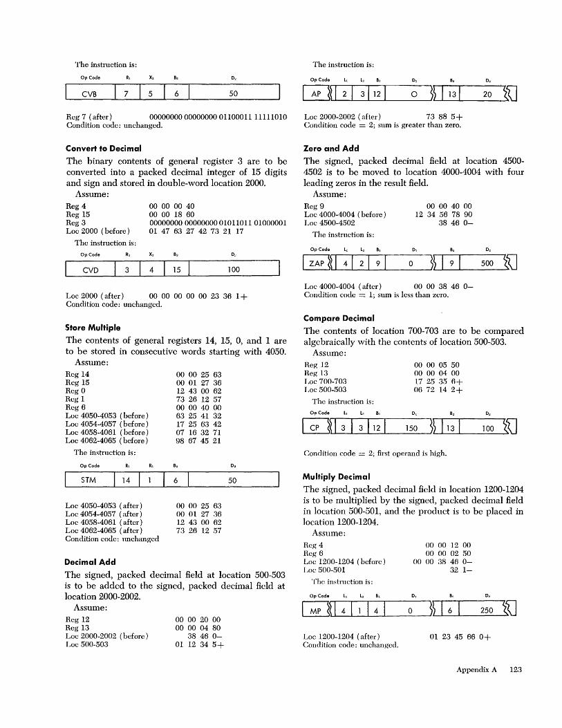
The instruction is:
Op Code x, 0,
CVB 7 5 6 50
Reg 7 (after) 00000000000000000110001111111010 Condition code: unchanged.
Convert to Decimal
The binary contents of general register 3 are to be converted into a packed decimal integer of 15 digits and sign and stored in double-word location 2000.
Assume: 00 00 00 40 00 00 18 60
Reg 4 Reg 15 Reg 3 Loc 2000 (before)
00000000 00000000 010 11 0 11 01000001 01 47 63 27 42 73 21 17
The instruction is:
op Code R, x,
CVD I 3 4 15 100
Loc 2000 (after) 00 00 00 00 00 23 36 1 + Condition code: unchanged.
Store Multiple
The contents of general registers 14, 15, 0, and 1 are to be stored in consecutive words starting with 4050.
Assume: Reg 14 Reg 15 Reg 0 Reg 1. Reg 6 Loc 4050-4053 (before) Loc 4054-4057 (before) Loc 4058-4061 (before) Loc 4062-4065 (before)
The instruction is:
Op Code Ra
00 00 25 63 00 01 27 36 12 43 00 62 73 26 12 57 00 00 40 00 63 25 41 32 17 25 63 42 07 16 32 71 98 67 45 21
0,
c=i_TM __ ~1 _14~1 __ ~_6~ _____ 50 ____ ~
Loc 4050-4053 (after) Loc 4054-4057 (after) Loc 4058-4061 (after) Loc 4062-4065 (after) Condition code: unchanged
Decimal Add
00 00 25 63 00 01 27 36 12 43 00 62 73 26 12 57
The signed, packed decimal field at location 500-503 is to be added to the signed, packed decimal field at location 2000-2002.
Assume: Reg 12 Reg 13 Loc 2000-2002 (before) Loc 500-503
00 00 20 00 00 00 04 80
38 46 0-01 1.2 34 5+
The instruction is:
Op Code L, L, B,
Loc 2000-2002 (after) 73 88 5+ Condition code = 2; sum is greater than zero.
Zero and Add
0,
20 i'U
The signed, packed decimal field at location 4500-4502 is to be moved to location 4000-4004 with four leading zeros in the result field.
Assume: Reg 9 Loc 4000-4004 (before) Loc 4500-4502
The instruction is:
OpC~e ~ k •
00 00 40 00 12 34 56 78 90
38 46 0-
0,
a O2
500 i'U Loc 4000-4004 (after) 00 00 38 46 0-Condition code = 1.; sum is less than zero.
Compare Decimal
The contents of location 700-703 are to be compared algebraically with the contents of location 500-503.
Assume: Reg 12 Reg 13 Loc 700-703 Loc 500-503
The instruction is:
00 00 05 50 00 00 04 00 1.7 25 35 6+ 06 72 1.4 2+
100 i'U Condition code = 2; first operand is high.
Multiply Decimal
The signed, packed decimal field in location 1200-1204 is to be multiplied by the signed, packed decimal field in location 500-501, and the product is to be placed in location 1200-1204.
Assume: Reg 4 Reg 6 Loc 1200-1.204 (before) r ,oc 500-501
The instruction is:
Op Code L, k Bl
Loc 1200-1204 (after) Condition code: unchanged.
a
00 00 12 00 00 00 02 50
00 00 38 46 0-32 1-
~~ I 6 I 250
01 23 45 66 0+
Appendix A 123

Divide Decimal
The signed, packed decimal field at location 2000-2004 is to be divided by the packed decimal field at location 3000-3001..
Assume: Reg 12 Reg 13 Loc 2000-2004 (before) Loc 3000-3001
The instmction is:
Op Code L, L, 8,
00 00 18 00 00 00 25 00 01 23 45 67 8+
32 1-
0,
200 ~~ 113 I Loc 2000-2004 (after) 38 46 0- 01 8+
o.
500 i'iJ where the quotient is 38460- and the remainder is 018+. Condition code: unchanged.
Pack
Assume locations 1000-1004 contain the following: ZI Z2 Z:3 Z4 S5
where Z =: four-bit zone code S == four-bit sign code
The field is to be in packed format with two leading zeros and placed in location 2500-2503. Reg 12 Reg 13 Loc 1000-1004 Loc 2500-2503 (before)
The instruction is:
OpCo~ ~ k L
00 00 10 00 00 00 25 00 ZI Z2 Z3 Z4 S5 ABC D
0,
o
Loc 2500-2503 (after) 00 12 34 5S Condition code: unchanged.
Unpack
o
Assume locations 2501-2503 contains the following fields:
12 34 5S
This field is to be put into zoned format and placed in the locations 1000-1004 where: S is a four bit sign code. Reg 12 Reg 13 Loc 2501-2503 Loc 1000··1004 (before)
The instruction is:
OpC~e ~ k L
~D 4121121 0
and results in
00 00 10 00 00 00 25 00 12 34 5S ABC D E
0, B.
Loc 1000-1004 (after) ZI Z2 Z3 Z4 S5 where Z is a four-bit zone code. Condition codc: unchanged.
124
Move with Offset
The unsigned three-byte field at location 4500-4502 is to be moved to location 5600-5603 and given the sign of the one byte field located at 5603.
Assume: Reg 12 Reg 15 Loc 5600-5603 (before) Loc 4500-4502
The instruction is: Op Code L, L2 8,
IMVO~~13121121 Loc 5600-5603 (after) Condition code: unchanged.
Move Immediate
00 00 50 00 00 00 40 00 77 88 99 0+ 12 34 56
0, B.
600 ~~ 115 1
01 23 45 6+
O2
500 i'iJ
A dollar sign ($) is to be placed in location 2100, leaving locations 2101-2105 unchanged. Let Z represent a four-bit zone.
Assume: Reg 12 Loe 2100-2105 (before)
The instruction is:
Op Code
MVI $
Loc 2100-2105 (after) Condition code: unchanged.
Move Numeric
00 00 20 00 ZO ZI Z2 Z3 Z5 ZO
8, 0,
12 100
$ ZI Z2 Z3 Z5 ZO
Let Z and Y represent four-bit zones. The numeric parts of the eight-bit characters in the field at locations 6070-6074 are to be replaced by the numeric parts of eight-bit characters at locations 8080-8084.
Assume: Reg 12 Beg 15 Loc 6070-6074 (before) Loc 8080-8084
The instruction is:
00 00 60 00 00 00 80 00 Yl Y2 Y3 Y4 Y5 Z3 Z6 Z9 Z7 Z8
Loe 6070-6074 (after) Y3 Y6 Y9 Y7 Y8 Condition code: unchanged.
Move Zones
Let Z and Y represent four-bit zones in the eight-bit characters making up the fields at location 2006-2010 and 3007-3011, respectively. The zones of the field at 2006-2010 arc to be replaced by the zones from location 3007-3011.
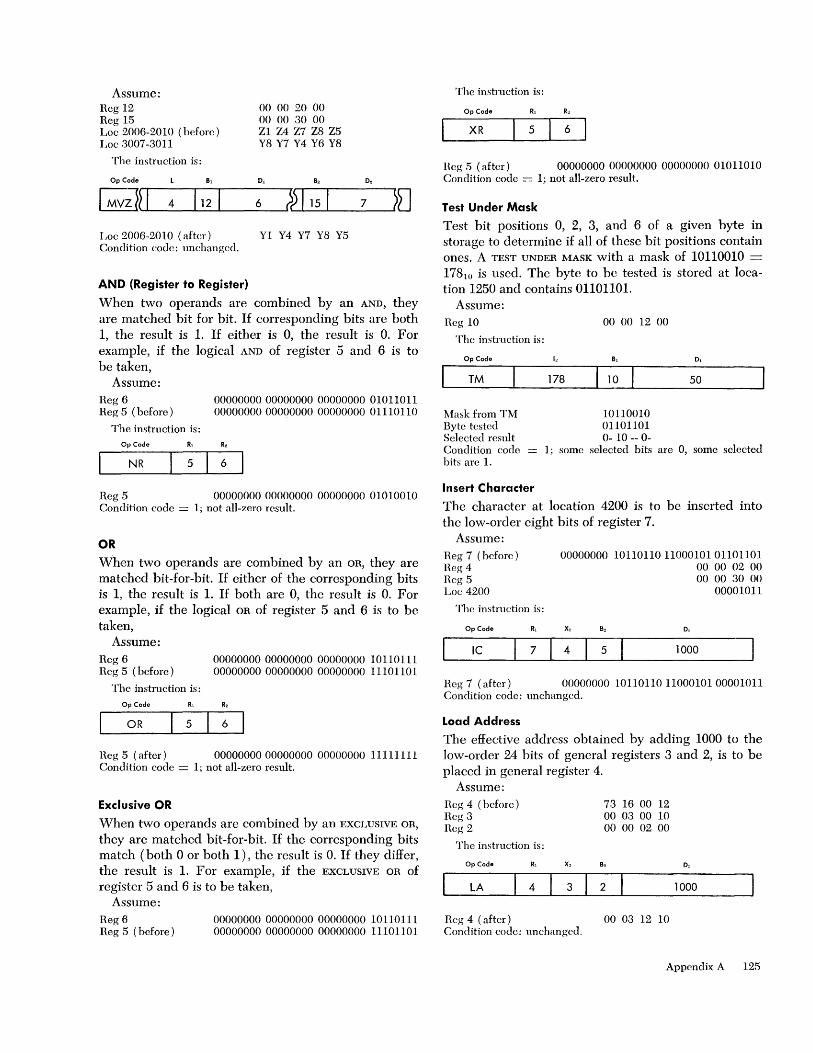
Assume: Reg 12 Reg 15 Loc 2006-2010 (before) Loc 3007-3011
The instruction is:
Op Code B,
00 00 20 00 00 00 30 00 Zl Z4 Z7 Z8 Z5 Y8 Y7 Y4 Y6 Y8
D,
6
Loc 2006-2010 (after) Y1 Y4 Y7 Y8 Y5 Condition codc: unchanged.
AND (Register to Register)
When two operands are combined by an AND, they are matched bit for bit. If corresponding bits are both 1, the result is 1. If either is 0, the result is O. For example, if the logical AND of register 5 and 6 is to be taken,
Assume: Reg 6 Reg 5 (before)
The instruction is: Op Code RJ
NR 5
00000000000000000000000001011011 00000000000000000000000001110110
6
Reg 5 00000000 00000000 00000000 01010010 Condition code = 1; not all-zero result.
OR
When two operands are combined by an OR, they are matched bit-for-bit. If either of the corresponding bits is 1, the result is 1. If both are 0, the result is O. For example, if the logical OR of register 5 and 6 is to be taken,
Assume: Reg 6 00000000 00000000 00000000 10110111 Reg 5 (before) 00000000 00000000 00000000 1110 11 0 1
The instruction is:
Op Code
OR 5 6
Heg 5 (after) 00000000 00000000 00000000 11111111 Condition code = 1; not all-zero result.
Exclusive OR
When two operands are combined by an EXCLUSIVE OR,
they are matched bit-for-bit. If the corresponding bits match (both ° or both 1), the result is O. If they differ, the result is 1. For example, if the EXCLUSIVE OR of register 5 and 6 is to be taken,
Assume: Reg 6 00000000 00000000 00000000 10110111 Reg 5 (before) 00000000 00000000 00000000 111011 0 1
The instruction is:
Op Code R,
XR 5 6
Beg 5 (after) 00000000 00000000 00000000 01011010 Condition code = 1; not all-zero result.
Test Under Mask
Test bit positions 0, 2, 3, and 6 of a given byte in storage to determine if all of these bit positions contain ones. A TEST UNDER MASK with a mask of 10110010 == 178 lO is used. The byte to be tested is stored at location 1250 and contains 01101101.
Assume: Beg 10 00 00 12 00
The instruction is:
Op Code '" D,
TM 178 10 50
t-.1ask from TM Byte testcd Selected result Condition code bits are 1.
Insert Character
10110010 01101101 0- 10 -- 0-
1; some selected hits are 0, some selected
The character at location 4200 is to be inserted into the low-order eight bits of register 7.
Assume: Reg 7 (before) Heg4 Reg 5 Loc 4200
The instruction is:
Op Code R,
Ie 7
00000000 10110110 11000101 01101101 00 00 02 00 00 00 30 00
00001011
x,
4 5 1000 J Reg 7 (after) 00000000 101101101100010100001011 Condition code: unchanged.
Load Address
The effective address obtained by adding 1000 to the low-order 24 bits of general registers 3 and 2, is to be placed in general register 4.
Assume: Reg 4 (before) Reg 3 Reg 2
The instruction is:
Op Code
LA 4
Reg 4 (after)
3
Condition code: unchanged.
73 16 00 12 00 03 00 10 00 00 02 00
2
00 03 12 10
1000
Appendix A 125
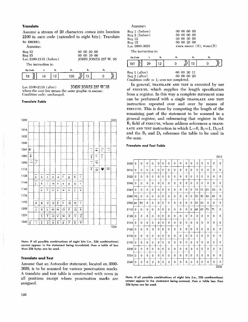
TranslatEt
Assume a stream of 20 characters comes into location 2100 in ASCII code (extended to eight bits). Translate to EBCDIC.
Assume: Reg 12 Reg 15
00 00 20 00 00 00 10 00
Loc 2100-2119 (before) JOliN JONES 257 W. 95
The instruction is:
0 , o.
100 ;) 115 o
Loc 2100-2119 (after) JOHN' JONES 257 W~95 where the over bar means the same graphic in EBCDIC.
Condition code: unchanged.
Translate Table
1000 r----
1015
1----t--4--t---+---t--+--+-+--+--,-' --"""t---+--+'-+----+----t
1016 f---l---+-+----+-.--I-,-,- --, ---, -,-,,' , -"'-, ""'--"-,--,
1032 - ~-
_. -_. --+--t---"-+-"-'j-'-- +-- ,- -,- ""'" - , ----~
1048 ,--'-
1064 BI +-'-+"""I-"--~--+--- ( +
1080 & $ * ) -
t"""--+- -'j-'-+-"- t----+---t-----jf----c-I--=' ,',' """-
Assume: Reg 1 (before) Reg 2 (before) Reg 12 Reg 15 Loc 3000-3029
The instruction is:
Op Code
00 00 00 00 00 00 00 00 00 00 30 00 00 00 20 00 UNPK PHOUT (9), WORD ( 5 )
0, 0,
~~r-r-1-2-9 ---"I:o-12--r-1--o ---;),--,-1"""-1 =15===0=--'J~ Reg 1 (after) 00 00 30 11 Reg 2 (after) 00 00 00 20 Condition code = 1; scan not completed.
In general, TRANSLATE AND TEST is executed by use of EXECUTE, which supplies the length specification from a register. In this way a complete statement scan can be performed with a single TRANSLATE AND TEST
instruction repeated over and over by means of EXECUTE. This is done by computing the length of the remaining part of the statement to be scanned in a general register, and referencing that register in the Rl field of EXECUTE, whose address references a TRANS
LATE AND TEST instruction in which L=O, Bl=1, Dl=1 and the B2 and D2 reference the table to be used 'in the scan.
Translate and Test Table
2015
1096 / -; % 2000 0 0 0 0 0 0 0 0 0 0 0 0 0 0 0 0 ,--- ---- -,-- -,- - -- -- ,-- - r'- f"--- -,--,--" '-
1112 @ ... = 2016 0 0 0 0 0 0 0 0 0 0 0 0 0 0 0 0 I---t----+-+---+---I-"-- -,---" -"-, '-,--, ---/----I----t- --
1128 abc de 9 hi f---t----t---j---+---I---j---- --" ",,--,1,--
1144 I---t--_--t_-t-__ --+-_m_-t-n--t_
o_ t-P , q ,',' 1 ,~- ",'
1160 u v w x y z I----t---j--t---t---t--/-----' -----t-'-+' "-f --- "-,- --,--"" ""
1176
1192
1208
1224
ABC D G H I I---t----j--I---t---t--t---t----t"-"-,-,--, ,"- ,,"--
K LMNOP QR ,-- ---- -_. __ .
,""",,-- ----
T U V W X y Z '""""'"
2 3 4 5 6 7 8 9 ,',-,-""- .... _--
,-,- ,-,--""-"" -,-
""
-- '""- --
1256
Note: If all possible combinations of eight bits (i.e., 256 combinations) cannot appear in the statement being translated, then a table of less than 256 bytes can be used.
Translate and Test
Assume that an Autocoder statement, located on 3000-3029, is to be scanned for various punctuation marks. A translate and test table is constructed with zeros in all positions except where punctuation marks are assigned.
126
2032 0 0 0 0 0 0 0 0 0 0 0 0 0 0 0 0 ---
2048 0 0 0 0 0 0 0 0 0 0 0 0 0 0 0 0 -- --
2064 0 0 0 0 0 0 0 0 0 0 0 10 15 20 25 0 -- ---
2080 90 0 0 0 0 0 0 0 0 0 0 30 35 40 45 0 -- --
2096 80 85 0 0 0 0 0 0 0 0 0 50 55 0 0 0 --
2112 0 0 0 0 0 0 0 0 0 0 0 60 65 70 75 0 f--- - -_.- --_.
2128 0 0 0 0 0 0 0 0 0 0 0 0 0 0 0 0 ~--- -"-_.-- 1-- ---I----- --,---I---- 1---- --
2144 0 0 0 0 0 0 0 0 0 0 0 0 0 0 0 0 .. _- ----
2160 0 0 0 0 0 0 0 0 0 0 0 0 0 0 0 0 1---I-- -" r---- --r---- -- ------
2176 0 0 0 0 0 0 0 0 0 0 0 0 0 0 0 0 -- - ,-"-"
2192 0 0 0 0 0 0 0 0 0 0 0 0 0 0 0 0 -- --,-
2208 0 0 0 0 0 0 0 0 0 0 0 0 0 0 0 0 -,---- I-- --, ---r---- - - -"'" '"
2224 0 0 0 0 0 0 0 0 0 0 0 0 0 0 0 0
2240 0 0 0 0 0 0 0 0 0 0 0 0 0 0 0 0 :-:-
2256
Note: If all possible combinations of eight bits (i.e., 256 combinations) cannot appear in the statement being scanned, then a table less than 256 bytes can be used.

Edit and Edit and Mark
The following examples show the step-by-step editing of a packed field with a length specification of four against a pattern 13 bytes long. The following symbols are used:
SYMDOL
b ( ) d
Assume:
MEANING
blank character significance start character field separator character digit-select character
Loc 1000-1012 (first operand) Loc 120-1203 (second operand) Reg 120
bdd,dd ( .ddbCR 02 57 42 6+
00 00 10 00
The instruction is:
OpCode D.
~~~1-1-2~1-12~1---o~»I~I-12~1--20-0~~
and provides the following:
PATTERN DIGIT S TRIGGER RULE LOCATION 1000-1012 b o leave(l)bdd, dd(. ddbCR d 0 o fill hhd, dd(. ddbCR d 2 1 digit bh2, dd(. ddbCR(2)
1 leave same 1 digit bh2, 5d(. ddbCR d 5
d 7 1 digit bb2, 57 (. ddbCR ( 4 1 digit bh2, 574. ddbCR
1 leave same d 2 1 digit bb2, 574. 2bdCR d 6+ o digit bb2, 574. 26bCR (3)
b o fill same C o fill bh2, 574, 26bbR R o fill bb2,574,26bbb
Thus: Loc 1000-1012 (after) bb2,574.26bCR
NOTES
1. This character is saved as the fill character. 2. First nonzero digit sets S trigger to 1. 3. Plus sign in this same byte sets S trigger to zero. Condition code = 2; result greater than zero.
If the second operand in location 1200-1203 is 00 00 02 6-, the following results are obtained:
Loc 1000-1012 (before) hdd, dd(. ddbCR Loc 1000-1012 (after) bbbbbbb. 26hCR Condition code = 1; result less than zero.
In this case the significance-start character in the pattern causes the decimal point to be left unchanged. The minus sign does not reset the S trigger so that the cn symbol is also preserved.
In the edit examples above, if the initial character of the pattern was an asterisk, then asterisk-protection would be achieved.
In the same example, if EDIT AND MARK was used:
Reg 1 (before) 00 12 34 56 Reg 1 (after) 00 00 10 02
Branch On Condition
Assume a prior operation has been perfonned which resulted in setting the condition code in the psw. The program is to branch if the result of the previous operation is nonzero.
The BRANCH ON CONDITION with a mask of 0111 == 710 in the Ml field becomes a branch-on-nonzero instruction.
Reg 5 00000100 Reg 12 00040000
The instruction is:
Op Code Ml X2 B2 D,
Be 7 5 12 100
and causes a branch to location 40,200, provided the condition code is not zero. Condition code setting is unchanged.
Execute
The ADD instruction at location 350 is to be executed by means of EXECUTE:
Assume: Reg 3 Reg 12 Loc 350
The instruction is:
Op Code
EX o X2
3
00 00 00 10 00 00 03 30 AR 4,6
12
D2
10
The CPU executes the ADD instruction and takes the next sequential instruction after EXECUTE.
The move character instruction MVC at location 1200 is to be executed, and the number of characters to be moved is computed in register 5.
Assume:
Reg 5 (rightmost 8 bits) Reg 7 Reg 13 Loc 1200 Length field (8 bits) =
The instruction is:
Op Code Rl X2
EX 5 7
01110000 = 11210
00 00 00 50 00 00 10 50 MVC 0, 15, 100, 12, 1000 00000000
B2
13 100
The rightmost eight bits of R5 arc OR' cd with the length portion (positions 8-15) of the instruction being executed, at location 1200 prior to execution of MOVE.
However, the actual instruction at location 1200 re-
Appendix A 127

mains unchanged, and the instruction actually exe-uted by EXECUTE is
Op Code B, 0, B. D.
I MvclIT 112 1151 100 ?~1121 100 ~LJ
to provide a move with a length of 112 bytes and thus move 113 bytes.
Assembly Language Examples These programming examples use the System/360 assembly-language format and mnemonics. In general, the operands are shown symbolically with indexing or length specification following the symbol and enclosed in parentheses. Lengths are given as the total number of bytes in the field. This differs from the machine definition regarding lengths which states that the length is the number of bytes to be added to the field address to obtain the address of the last byte of the field. Thus the machine length is one less than the assembly-language length. The assembly language automatically subtracts one from the length specified when the instruction is assembled.
Examples
l. Decimal right shift - even number of places. Assume symbolic location "Source" is: Source: 12 34 56 78 9S and we wish to drop two places. MOVE NUMERICS (MVN) can be used to accomplish this
Source MVN Source + 3 (1), Source + 4 12 34 56 7S 9S ~y usin~ a length of 4 instead of 5 in operations using sym
bohc locatIOn Source, the result is accomplished.
2. Decimal right shift - odd number of places. Source: 12 34 56 78 9S
Assume we wish to drop three places. The move with offset (MVO) instmction is used.
Source MVO Source (5), Source (3) 00 01 23 45 6S
3. Decimal left shift - even number of places. Assume tbe following at symbolic location "ZERO."
Zero: 00 00 Source: 12 34 56 78 9S
A left shift of four places can be performed as follows:
Source MVC Source + 5 (2), Zero 12 34 56 78 9S 00 00 MVN Source + 6 (1), Source + 4 12 34 56 78 9S 00 OS NI Source + 4,240 12 3456 78 90 00 OS
. Note the number 24010 in the AND IMMEDIATE instmction proVIdes a mask of 11110000 which is to be used to make the old sign positions zero.
128
4. Decimal left shift - odd number of places. Zero: 00 00 Source: 12 34 56 78 9S Assume the shift to be three places.
Source MVC Souree + 5 (2), Zero MVN Source + 6 (1), Source + 4 NI Souree + 4, 240 MVO Source (6), Source (5)
12 34 56 78 9S 00 00 12 34 56 78 9S 00 OS 12 34 56 78 90 00 OS 01 23 45 67 89 00 OS
5. A master inventory file is to be updated by issue and receipt transactions. There may be multiple transactions pertaining to a master record. Both inactive and updated master records are to be rewritten. The following calculations are performed to update the master:
Receipts
l. Receipt quantity X unit cost == receipt cost 2. Receipt cost + total cost == new total cost 3. Receipt quantity + quantity on hand new
quantity 4. New total cost --;- new quantity == new average
unit cost
Issues
l. Quantity on hand - issue quantity == new quantity (if quantity on hand is less than issue quantity, go to an exception routine) .
2. Issue quantity X average unit cost == issue cost 3. Total cost -issue cost == new total cost 4. If new quantity is not greater than the reorder level,
go to an exception routine. >
Record Description
NI aster Record: Item #: 6 alphameric characters Description: 20 alphabetic characters Quantity: 7 digits plus sign Total cost: 11 digits plus sign (2 decimal places) Average unit cost: 7 digits plus sign (3 decimal places) Reorder level: 5 digits plus sign
Transaction Record: Type code: 1 digit plus sign (plus 1 == receipt) ( plus 2 == issue) Item #: 6 alphameric characters Quantity: 5 digits plus sign Receipt unit cost: 6 digits plus sign (2 decimal places)
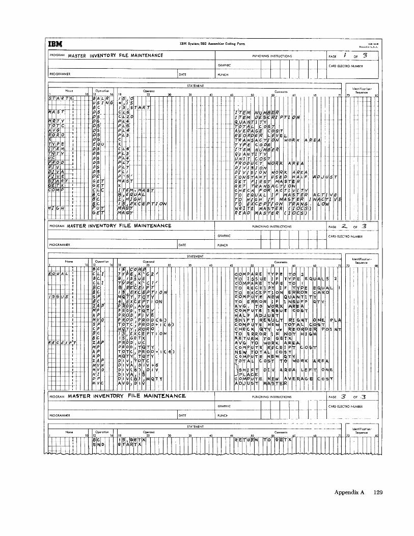
IB14 IBM System/3S0 ABBembler CDding PDrm
PROGRAM MASTER INVENTOR'!' FILE MAINTENANCE PUNCHING INSTRUCTIONS PAGE I OF :3 I-------------+-G-RAPH-'C ------,I,---~II ~I--'-1 -'-1 --.-1-+----··--
CARD ELECTRO NUMBER
~P-RO-G-R-AM-M-ER-----------------------------------'----------~-P-U-NC-H---------I~-~I-~I-~I-+-I-+-I-+-I-4
Nome Operation 1 10 12 16 STA R T X. f.-- BA LR
I USI NG t· f-- -f.-
Ml4-S fC- --L 8 C I OS I • os
M~T )7- ·t ]05 I TO TC I DS 1-
IAVG • .. 0 5
BJl &12 OS I
t X I 05
-
TV PE I eQU 1-·
fr~1 M +C--H--~~ --- -
Yc- ., uc • DS IPI? 00 1 DS OI V I OS IDli VA 05 IFIT VE Oc
18 Operand
25
/5,1 0 *) I 5 15 J START CL6 c. i.. -20 -PJ.4 .. -
PL6 - Pi..4 PL3 c X. CL6 Ii 3 !Pili PJ.7 PL7 I'Ll P \ 5 I
--..
.. _ ..
...
T I .. -S1A RT I GE E. T X I GET
~~~-H'-+-+-+--+-~=-i-!C"H-+ .~I'-~~~ A 5 i X c--t--I--
CO MP .-"t-
- +--+-- -I-' I r
HIr~ H~ -"t --L_
I T
-I---~~C Be Be. PUT G£"T
I TE M; ~Arstr--6,EQUAL. 2."HIGH ~~rSl~ xci: PiT JoIN M~6IT
30
PROGRAM MASTE.R INVENTORY FILE. MAINTE.NANCE.
I DATE
STATEMENT
35 40
-I
-1-
1·- -
I
1--1-
Identificatlon-Comments
~ ITE~ ~ N~W8C 'If f60 I II~ .. ~ ~TEM O~SCRIPT N ~UANTI TV
c- T'O TAL cos l7 I I AVERAGE COST I I
173 Sequence
f·
i---
,.
R S 0 Rip E R LEveL I I + - TRANSAC-TlrON wOfqK A~IIEA
TYPE COOS ITEM Nu1M.8ER
I .. 1-f.-
1+-
- - QU ANITI TY II II. UNIT COS7
f- -
-1-1-- PRO 0 U C 7 WOR J< ARE AI I DIVISION .. I
O~V/~/OW WORK ARE~ I
1+ "- 0 'tJ S r A IV.. T tJ s c 0 HAL IF IA 0 JUS T GET FIRST M.ASTER I I GeT ITRANSACTIO~ I C He C I( FOR ACT 11 vITI y I
~g Z~~~L,kFM:~~~~rJ~~r~Y~!
.r 0 EX c'IE P Tit q~ ~R A NI5 .1 L Ol~ Iv. R 1 T E MAS 7 c R (laC 5) I READ MA~TER (laCS) I _. I
1-1--+--+--1-++--+
PUNCHING INSTRUCTIONS PAGE 2... OF .3
GRAPHIC
,8Q
i-·
1-
t--
I I I CARD ELECTRO NUMBER ~P-RO-G-R-AM-M-E-R----------------------------------'I-DA-T-E--------~-PU-N-CH-----------~I~--+---~I-+I--4--+----l
Nome Operation Operand 10 12 16 18 25 30
'---i-t--t---f--+=:B_+C I 5 COM P ~Q"u A L -: I eLI.... T y ~ E .J. ~ ... C Z I
~--l---Ie--+-+--L 8 C. 8 ISS U E--f- - c-:- eLI TV P E ) )( ... C 1 I _I-- _I _ t 8 C 8 ) 1? E eEl P T
~+--l---+--+--l-_ _I_--I----I--I~ii, t _ 1!i:1i; ~ K £: ~ j:J T I 01111 ISSUE I SP MQTY-!.TQTY
f ~Z'ACp. !~.G.XCg.P.I'ON I-+----l---II--++-t---+-++--+---jl~ l' ROD , A V G I-+----l---If--+--I---I---+-++ + M P J'- ROD ) T <n:. Y
I AP PROD FI VE 1-+--_-I-~-+----I-~--+-._'~-+I--++--l-+-~~I'o'M,~V;'-+O -- p~ ~ 9 D ~ t'R q D C ~ )
SP TOTC,PROO+I(6) I--+--+-+-+---i rep ..... ~9 T Y , R Q R. 0
I--I--f.- __ . 1 8 c 1.3 I E X <: E P r.r ION I IJC 15)GET~
R'€+C Ii I!P~T ZAP PROD I U C. /tiP PROD)TQTY
1--+--+-+-+---+ +1- APT 0 T C. ) PRODoj- I ( 6 ) 1--1-- _ A P ", Q TV) T Q T Y
I--+--+-+---+---+--+-' _+---+---I_-_I_--+"Z ~e p I V J TOT C MVN DIVA)OlV+6
-+--~- - ~ + "t
_ /-_1·.. 1 I 1--+--+-+-+---+-, I
MVe> DI V(S)l.D I Y N I D I \I A, I!) OP Dlvced"MQTY ~VC AVG)DIV
_L_l_ .
PROGRAM MASTER INVE.NTORY FILE MAINTf.NANCE.
STATEMENT
35 40 45 Comments
50 55 1 t T1--I42 -
_. 71 ~
co,., PAR e T Y pelT 0 III I TO ISS U ElF T Y P E IE Qlu A L 5 2 COM PAR E Tly peT 0 II I TO R e eel P T 1FT" P E IE QUA L I Toe XC E P T ~ 0 N e R ROIR Ie A R 0 COMPUTE NeW QUANTII Tlv
~ ••. ~ G: R~ ~R. w.b ... ~ K 1 i~ ~~I~IF IQ TV COM P V Tel 6 9 U! e 0 &IT I
HALf ADJUST I SH'F~. RE6U. L.T RI~~T_IO. ~E_PLA CO~PUTE N61w TO~Al COST CHECK IGlil~ v~hReo oelR POl Nl TO 1: R R 0 R 1 1= N of. H 1 GIH Fl e T II R N ToG E Tlx. I I A V & T 01'" 0 R KARlE A.I I I co,..,? U T Ii -RG c. e 1 pIT ~IO SiT N E Iw TOT ALe 0 5 T, I I colMPUTE NEW QTY II I ~O~AL COST TO I~ORK ~REA
ISH1 fT DI V A ReA LIEF!T ONE.
1-' PLACE II I C 011>1 PUT E. HE. W A vie RAIG el Cos T ADJUST MASTER I
I PUNCHING INSTRUCTIONS
Identification-
r1"l1" II I I
I I I I
I I
I I
1
PAGE 3 OF ,3 -.--~----------~-----
I-P-RO-G-RA-M-M-ER-----------------------------------.--IDA-TE----------l-:-:-::-:-IC------------"If--+---t--l~ ± I + :.'-"''''0 '""'"
1-__________ --r.--___ ---,--.-____________________ -..:S~TA::.cT~EM~EN~T ___________________________________ .. ___ "
Name Identlfication
Sequence
Appendix A 129
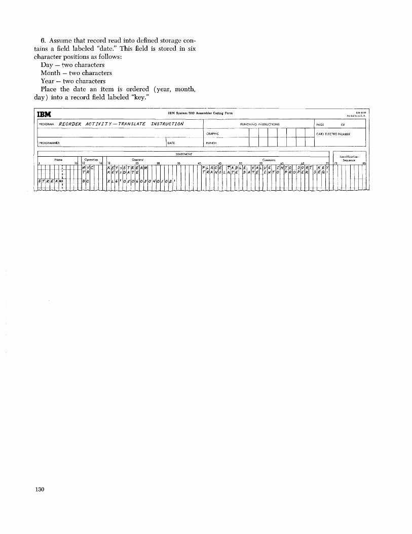
6. Assume that record read into dcfincd storage contains a field labeled "date." This field is stored in six character positions as follows:
Day - two characters Month - two characters Year - two characters Place the date an item is ordered (year, month,
day) into a record field labeled "key."
--------
IBM IBM System/360 ABBBmblBr Coding Form
PROGRAM REORDER. ACTIVITY - TRANSLATE INSTRUCTION PUNCHING INSTRUCTIONS
GRAPHIC I I PROGRAMMER I DATE PUNCH I I
STATEMENT
Name Operation Operand Comments 1 10 12 16 18 25 30 35 40 45 50 55 0 -r-~ 1--- -- -:-~-]-- M VC KE Y , ST R£ AM Pl- ACE TA lJL t- VA L()E IN r-~I I·· iT R KE Y 3 DA TE TR. AN S L ATE ]) A T~ IN TO
scr RE A~!-·· _ B C XL 6 ' OS" 06 O~ 0'1 01 02' I
t .. f- ...... , ... I -1-
130
--X28-6S09
Prinled in U,S.A.
PAGE OF
I CARD ELECTRO NUMBER
I Identificction-
Sequence 65 71 73 80
TO SO RT KEY PR. oP {R SE Q.
t --
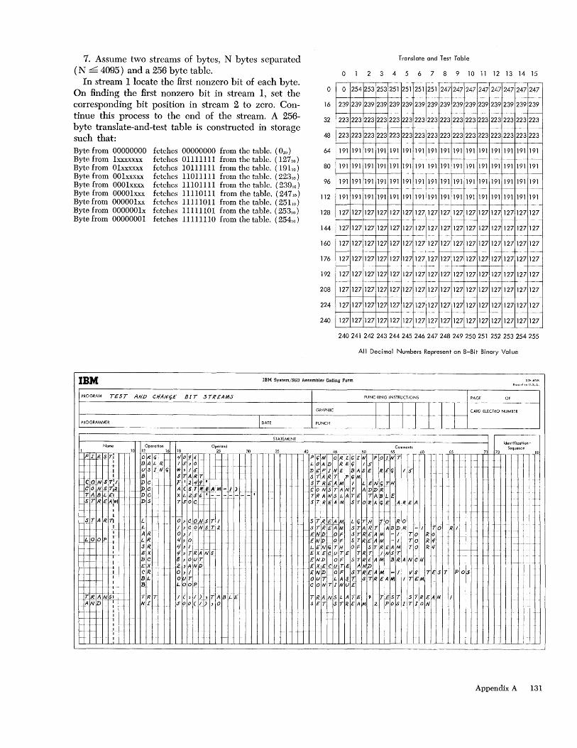
7. Assume two streams of bytes, N bytes separated (N L 4095) and a 256 byte table.
Translate and Test Table
o 2 3 4 5 6 7 8 9 10 11 12 13 14 15 In stream 1 locate the first nonzero bit of each byte.
On finding the first nonzero bit in stream 1, set the corresponding bit position in stream 2 to zero. Continue this process to the end of the stream. A 256-byte translate-and-test table is constructed in storage such that: Byte from 00000000 Byte from lxxxxxxx Byte from 01xxxxxx Byte from 001xxxxx Byte from 0001xxxx Byte from 00001xxx Byte from 000001xx Byte from 0000001x Byte from 00000001
fetches fetches fetches fetches fetches fetches fetches fetches fetches
00000000 from the table. (OJO) 01111111 from the table. (12710 )
10111111 from the table. (191 10 )
11011111 from the table. (22310 )
11101111 from the table. (23910 )
11110111 from the table. (24710) 11111011 from the table. (25110) 11111101 from the table. (25310 )
11111110 from the table. (25410 )
o
16
32
48
64
80
96
112
128
144
160
176
192
208
224
240
o 254 253
239 239 239
223 223 223
223 223 223
191 191 191
191 191 191
191 191 191
191 191 191
127 127 127
127 127 127
127 127 127
127 127 127
127 127 127
127 127 127
127 127 127
127 127 127
.. _.-
253 251 2 51 251 251 247
239 2392 39239239 239
223 2232 23223223 223 - -
223 2232 23223223 223
191 191 1 91 191 191 191 --
191 191 1 91 191 191 191 I-
191 191 1 91 191 191 191 ~-
191 191 1 91 191 191 191 1-----
127 1271 27 127 127 127
127 1271 27 127 127 127
127 1271 27127127 127 I---
127 1271 27127127 127
127 1271 27 127 127 127
127 1271 27 127 127 127
127 1271 27 127 127 127 --
127 1271 27 127 127 127
--r--
247 247 247 247 247 247 247 --- - ."- ----
239 239 239 239 239 239 239 --- -- ---
223 223 223 223 223 223 223 • ----- --~ I--- --(----
223 223 223 223 223 223 223
191 191 191 191 191 191 191 1---- f------- - -- ---f.---1--
191 191 191 191 191 191 191 --1----f.---- --
191 191 191 191 191 191 191 --- --- -- I--1----1--- --
191 191 191 191 191 191 191 f.-- f--- -" --127 127 127 127 127 127 127
-- ---- ---I----I-- --- - -
127 127 127 127 127 127 127 --1------ --- -- f----1--- ---
127 127 127 127 127 127 127 1----- 1---- 1---- ---
127 127 127 127 127 127 127 - --- I---- ---~ 1-----1-- - t--
127 127 127 127 127 127 127 -- I--1----1--- ---
127 127 127 127 127 127 127 ---[----J- - -
127 127 127 127 127 127 127 -- - -- --- - ----- -- ---t-
127 127 127 127 127 127 127
240 241 242 243 244 245 246 247 248 249 250 251 252 253 254 255
All Decimal Numbers Represent an 8-Bit Binary Value
IBM IBM SYBtem/360 Aesumbler Coding Form
PROGRAM TEST AND Cf/AN(j£ BIT STREAMS PUNCHiNG iNSTRUCTiONS PAGE OF
I I ti t-FF
--- .-
GRAPHiC CARD ELECTRO NUMBER
PROGRAMMER I DATE PUNCH T T STATEMENT
Identification-Name Operation Operand Comments Sequence
1--!-r-...,,---,-,--,;-r-~,-'I'-"10 ----I-'-'12T-,_~-~1~6 _+-"',18 _T_-.--T2=,5,--,-,--r-r=3.:;-0 --.--,,-,=35.-,-,-,-,4.:;-0 -c::-r-.-T----r=45'-r---,--.-- , __ 50 ___ "~ ~ _ _ ,Q.Q _ _ _ _ 45"r-r---.--,-,-_~71 f-----l-'-7",3 -,--,,---,--_,-_, -i?O I-~~ I?- ~- T:_ 0 J'l Ii "t'19 , f- P Ii M 0 R L G I II POI W T i _ I-~_I- _ 1-1 B A L R I " , 0 _ I-- I-- __ I- 0 A P.c-: R E (j I S I- - I U S_ I II Cj *, / oS" D €f J II E 13 A S £ R. E <i 1 S-
I B _ START ~_ START l'<iM ~~(}NS7};--=i~ DC F' 249' S;L8EAM I L ENg Ttf
q 0 IV. S Tl~1- Iv C f=- -A ( S T R ~ A M - I )_ 1 __ C 0 (II ~ TAN TAD D R __ r~ B L £1 1-__ 1_ D C X L 2 oS" 6 • - - - foO - - - • __ _ T RAN S ~ ATE T A 'B L £.
.§. T R. £ A;M i- _ D S· - 7 SO CST REA M- S TO 1( A q £. ARE A I
- -- -- I .s: LA ~ 7) -I-lc--}---I--l,L""-\
-'_ L I AR
i&-0t-t---! LR I __ •. S(R
EX BC EX
~-l---+---+-+--+-:_C R f---f-I---+-Ih-I +-+_I---+"~ L
1-
TRANSII--AND r
TR T NI
+1-
+--t-- ---1--- I
-:-
----f---I---- -1--
i- O,COi-1STI ( 1 C Q IV. ~tI- 2 0) I t/,O t/,I
j-
'I, TR.,4 N i 8 ,ouT Z)AND o , I I---OU T LOOP -1--
I(,I),TABL£ SOO(I),O
f--
f- -- -
ST~£AM LGTH TO RO I-- S T R'£~ M S TAR TAD D R - ITO
-i--
E 1'112+- 0 F S T R £ A M - / TOR 0 ENDI-0F STREAM -/IITO R'I LiN ~ i H 0 F S T R £ AM TO, R'II £ X E C (j T E T R TIN S T/ / I / £ NiD ..• 0 F 5 T R £ A M BRA N C H . .
£ X £ C (j T E A["lv I' I EN',Z)r-_.--.OF. STREAM. -I VS IT£_·.sT OuT LAST STREAM ITEM
CONTiNUE I
;~A~SLATE • rEiT ST'EA~ HT STRW Z POSlf ON I
i- i
I--
-1--
-- +-j-
R I f
f- ...
1- - -
f-I---j-._-
f- -t--
P OS
--
I- ..
-------~---
Appendix A 131
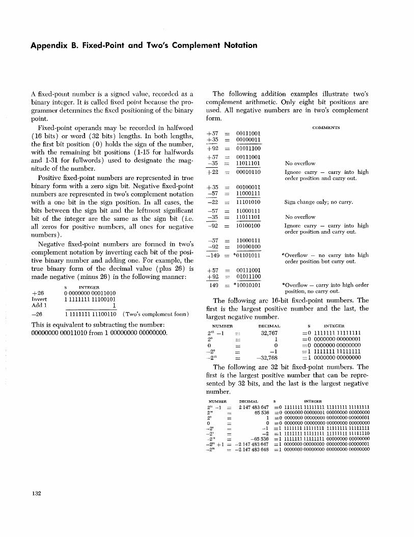
Appendix B. Fixed-Point and Two's Complement Notation
A fixed-point number is a signed value, recorded as a binary integer. It is called fixed point because the programmer determines the fixed positioning of the binary point.
Fixed-point operands may be recorded in halfword (16 bits) or word (32 bits) lengths. In both lengths, the first bit position (0) holds the sign of the number, with the remaining bit positions (1-15 for halfwords and 1-31 for fullwords) used to designate the magnitude of the number.
Positive fixed-point numbers are represented in true binary form with a zero sign bit. Negative fixed-paint numbers are represented in two's complement notation with a one bit in the sign position. In all cases, the bits between the sign bit and the leftmost significant bit of the integer are the same as the sign bit (i.e. all zeros for positive numbers, a1l ones for negative numbers).
Negative fixed-point numbers arc formed in two's complement notation by inverting each bit of the positive binary number and adding one. For example, the true binary form of the decimal value (plus 26) is made negative (minus 26) in the following manner:
+26 Invert Add 1
-26
S INTEGER
o 0000000 00011010 1 1111111 11100101
1
1111111111100110 (Two's complement form)
This is equivalent to subtracting the number: 0000000000011010 from 1 0000000000000000.
132
The following addition examples illustrate two's complement arithmetic. Only eight bit positions are used. All negative numbers are in two's complement form.
COMMENTS
+57 00111001 +35 00100011
+92 01011100
+57 00111001 -35 11011101 No overflow
+22 00010110 Ignore carry - carry into high order position and carry out.
+35 00100011 -57 11000111
-22 11101010 Sign change only; no carry.
-57 11000111 -35 11011101 No overflow
-92 10100100 Ignore carry - carry into high order position and carry out.
-57 11000111 -92 10100100
-149 (/01101011 (/Overfiow - no carry into high order position but carry out.
+57 00111001 +92 01011100
149 (/10010101 (/Overflow - carry into high order position, no carry out.
The following are 16-bit fixed-point numbers. The first is the largest positive number and the last, the largest negative number.
NUMBER DECIMAL S INTEGER
2 '0 -1 32,767 =0 1111111 11111111 2° 1 = 0 0000000 00000001 0 0 = 0 0000000 00000000
_2° -1 =1111111111111111 __ 2]" -32,768 = 1 0000000 00000000
The following are 32 bit fixed-point numbers. The first is the largest positive number that can be represented by 32 bits, and the last is the largest negative number.
NUMBER
231 -1 2·'fl 2° o --2" -2' _218 __ 281 +1 = _231
DECIMAL
2147483647 65536
1 o
-1 -2
-65536 -2 147483647 -2 147483 648
INTEGER
=0 111111111111111 11111111 11111111 = 0 0000000 00000001 00000000 00000000 = 0 0000000 00000000 00000000 00000001 = 0 0000000 00000000 00000000 00000000 = 1 111111111111111 11111111 11111111 =1 111111111111111 1111111111111110 = 1 1111111 11111111 00000000 00000000 = 1 0000000 00000000 00000000 00000001 = 1 0000000 00000000 00000000 00000000
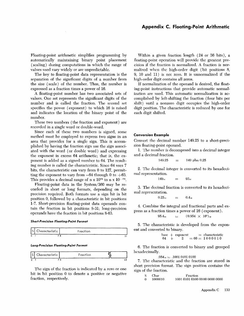
Floating-point arithmetic simplifies programming by automatically maintaining binary point placement ( scaling) during computations in which the range of values used vary widely or are unpredictable.
The key to floating-point data representation is the separation of the significant digits of a number from the size (scale) of the number. Thus, the number is expressed as a fraction times a power of 16.
A floating-point number has two associated sets of values. One set represents the significant digits of the num ber and is called the fraction. The second set specifies the power (exponent) to which 16 is raised and indicates the location of the binary point of the number.
These two numbers (the fraction and exponent) are recorded in a single word or double-word.
Since each of these two numbers is signed, some method must be employed to express two signs in an area that provides for a single sign. This is accomplished by having the fraction sign use the sign associated with the word (or double word) and expressing the exponent in excess 64 arithmetic; that is, the exponent is added as a signed number to 64. The resulting number is called the charactcristic. Since 64 uses 7 bits, the characteristic can vary from 0 to 127, permitting the exponent to vary from -64 through 0 to +63. This provides a decimal range of n x 1075 to n x 10-78 •
Floating-point data in the System/360 may be recorded in short or long formats, depending on the precision required. Both formats use a sign bit in bit position 0, followed by a characteristic in bit positions 1-7. Short-precision floating-point data operands contain the fraction in bit positions 8-31; long-precision operands have the fraction in bit positions 8-63.
Short-Precision Floating-Point Format
Is I Characteristic I Fraction o 1 7 8 31
Long-Precision Floating-Point Format
l~s~I_C_h_a_ra_c_t_e_ri_st_ic~I _________ F_ra_c_ti_o_n ______ ~~S~ ____ ~ o 1 7 8 63
The sign of the fraction is indicated by a zero or one bit in bit position 0 to denote a positive or negative fraction, respectively.
Appendix C. Floating-Point Arithmetic
Within a given fraction length (24 or 56 bits), a floating-point operation will provide the greatest precision if the fraction is normalized. A fraction is normalized when the high-order digit (bit positions 8, 9, 10 and 11) is not zero. It is unnormalized if the high-order digit contains all zeros.
If normalization of the operand is desired, the floating-point instructions that provide automatic normalization are used. This automatic normalization is accomplished by left-shifting the fraction (four bits per shift) until a nonzero digit occupies the high-order digit position. The characteristic is reduced by one for each digit shifted.
Conversion Example
Convert the decimal number 149.25 to a short-precision floating-point operand.
1. The number is decomposed into a decimal integer and a decimal fraction.
149.25 149 plus 0.25
2. The decimal integer is converted to its hexadecimal representation.
14910
3. The decimal fraction is converted to its hexadecimal representation.
0.2510
4. Combine the integral and fractional parts and express as a fraction times a power of 16 (exponent).
95.4]6 (0.954 X 162 ha
5. The characteristic is developed from the exponent and converted to binary.
base + exponent characteristic 64 + 2 = 66 = 1 0 0 0 0 1 0
6. The fraction is converted to binary and grouped hexadecimally.
.95410 = .1001 0101 0100 7. The characteristic and the fraction are stored in
short precision format. The sign position contains the sign of the fraction.
S Char Fraction o 1000010 100101010100000000000000
Appendix C 133

The following are sample normalized short floatingpoint numbers. The last two numbers represent the smallest and the largest positive normalized numbers.
NUMBER POWERS OF 16 S CHAR FRACTION
1.0 -- +1116 X 161 =0 1000001 0001 0000 0000 0000 0000 0000 0.5 +8/16 X 16° =0 1000000 1000 0000 0 000 0000 0000 0000 1164 +4/16 X l6-1 =0 0111111 a 100 0000 0000 0000 0000 0000 0.0 -- +0 x l6-61 =0 0000000 0000 0000 0000 0000 0000 0000
-15.0 -- -15/16 X 161 =1 1000001 1111 0000 0000 0000 0000 0000 2 X 10-78 -- +1116 x l6-61 =0 0000000 0001 0000 0000 0000 0000 0000 7 X 1075 -- (1-16-6
) X 1663 =0 1111111 11111111 1111111111111111
134
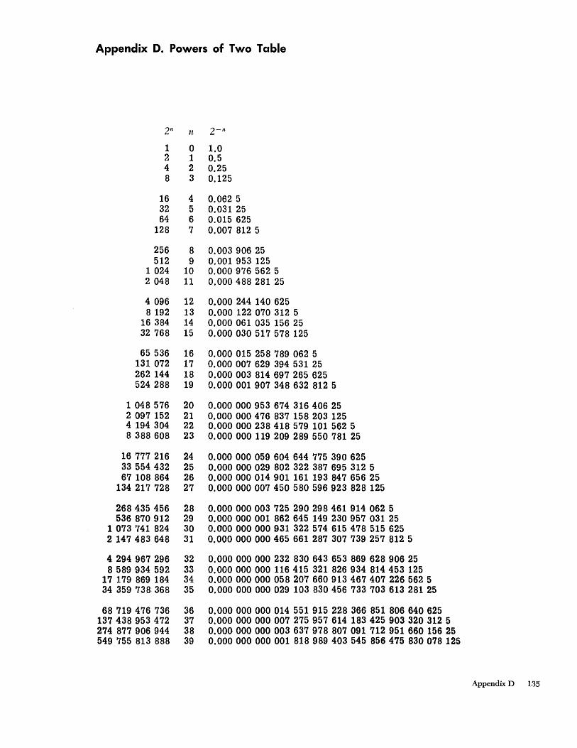
Appendix D. Powers of Two Table
2n n 2- 11
1 0 1.0 2 1 0.5 4 2 0.25 8 3 0.125
16 4 0.062 5 32 5 0.031 25 64 6 0.015 625
128 7 0.007 812 5
256 8 0.003 906 25 512 9 0.001 953 125
1 024 10 0.000 976 562 5 2 048 11 0.000 488 281 25
4 096 12 0.000 244 140 625 8 192 13 0.000 122 070 312 5
16 384 14 0.000 061 035 156 25 32 768 15 0.000 030 517 578 125
65 536 16 0.000 015 258 789 062 5 131 072 17 0.000 007 629 394 531 25 262 144 18 0.000 003 814 697 265 625 524 288 19 0.000 001 907 348 632 812 5
1 048 576 20 0,000 000 953 674 316 406 25 2 097 152 21 0,000 000 476 8"37 158 203 125 4 194 304 22 0.000 000 238 418 579 101 562 5 8 388 608 23 0,000 000 119 209 289 550 781 25
16 777 216 24 0,000 000 059604 644 775 390 625 33 554 432 25 0.000 000 029 802 322 387 695 312 5 67 108 864 26 0,000 000 014 901 161 193 847 656 25
134 217 728 27 0.000 000 007 450 580 596 923 828 125
268435 456 28 0,000 000 003 725 290 298 461 914 062 5 536 870 912 29 0,000 000 001 862 645 149 230 957 031 25
1 073 741 824 30 0,000 000 000 931 322 574 615 478 515 625 2 147 483 648 31 0,000 000 000 465 661 287 307 739 257 812 5
4 294 967 296 32 0,000 000 000 232 830 643 653 869 628 906 25 8 589 934 592 33 0,000 000 000 116 415 321 826 934 814 453 125
17 179 869 184 34 0,000 000 000 058 207 660 913 467 407 226 562 5 34 359 738 368 35 0,000 000 000 029 103 830 456 733 703 613 281 25
68 719 476 736 36 0,000 000 000 014 551 915 228 366 851 806 640 625 137 438 953 472 37 0,000 000 000 007 275 957 614 183 425 903 320 312 5 274 877 906 944 38 0,000 000 000 003 637 978 807 091 712 951 660 156 25 549 755 813 888 39 0,000 000 000 001 818 989 403 545 856 475 830 078 125
Appendix D 135
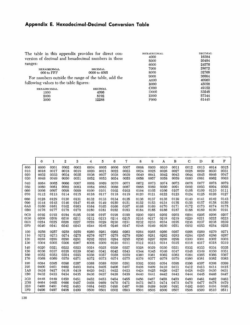
Appendix E. Hexadecimal-Decimal Conversion Table
The table in this appendix provides for direct conversion of decimal and hexadecimal numbers in these ranges:
HEXADECIMAL
000 to FFF DECIMAL
0000 to 4095
For numbers outside the range of the table, add the following values to the table figures:
000 010 020 030 040 050 060 070 080 090 OAO OBO OCO ODO OEO OFO
100 110 120 130 140 150 160 170 180 190 lAO IBO leO 1DO lEO 1FO
136
HEXADECIMAL
1000 2000 3000
0 1
0000 0001 0016 0017 0032 0033 0048 0049 0064 0065 0080 0081 0096 0097 0112 0113 0128 0129 0144 0145 0160 0161 0176 0177 0192 0193 0208 0209 0224 0225 0240 0241
0256 0257 0272 0273 0288 0289 0304 0305 0320 0321 0336 0337 0352 0353 0368 0369 0384 0385 0400 0401 0416 0417 0432 0433 0448 0449 0464 0465 0480 0481 0496 0497
2
0002 0018 0034 0050 0066 0082 0098 0114 0130 0146 0162 0178 0194 0210 0226 0242
0258 0274 0290 0306 0322 0338 0354 0370 0386 0402 0418 0434 0450 0466 0482 0498
3
0003 0019 0035 0051 0067 0083 0099 0115 0131 0147 0163 0179 0195 0211 0227 0243
0259 0275 0291 0307 0323 0339 0355 0371 0387 0403 0419 0435 0451 0467 0483 0499
DECIMAL
4096 8192
12288
4 5
0004 0005 0020 0021 0036 0037 0052 0053 0068 0069 0084 0085 0100 0101 0116 0117 0132 0133 0148 0149 0164 0165 0180 0181 0196 0197 0212 0213 0228 0229 0244 0245
0260 0261 0276 0277 0292 0293 0308 0309 0324 0325 0340 0341 0356 0357 0372 0373 0388 0389 0404 0405 0420 0421 0436 0437 0452 0453 0468 0469 0484 0485 0500 0501
6 7
0006 0007 0022 0023 0038 0039 0054 0055 0070 0071 0086 0087 0102 0103 0118 0119 0134 0135 0150 0151 0166 0167 0182 0183 0198 0199 0214 0215 0230 0231 0246 0247
0262 0263 0278 0279 0294 0295 0310 0311 0326 0327 0342 0343 0358 0359 0374 0375 0390 0391 0406 0407 0422 0423 0438 0439 0454 0455 0470 0471 0486 0487 0502 0503
HEXADECIMAL
8
0008 0024 0040 0056 0072 0088 0104 0120 0136 0152 0168 0184 0200 0216 0232 0248
0264 0280 0296 0312 0328 0344 0360 0376 0392 0408 0424 0440 0456 0472 0488 0504
4000 5000 6000 7000 8000 9000 AOOO BOOO COOO DOOO EOOO FOOO
9
0009 0025 0041 0057 0073 0089 0105 0121 0137 0153 0169 0185 0201 0217 0233 0249
0265 0281 0297 0313 0329 0345 0361 0377 0393 0409 0425 0441 0457 0473 0489 0505
A
0010 0026 0042 0058 0074 0090 0106 0122 0138 0154 0170 0186 0202 0218 0234 0250
0266 0282 0298 0314 0330 0346 0362 0378 0394 0410 0426 0442 0458 0474 0490 0506
B C
0011 0012 0027 0028 0043 0044 0059 0060 0075 0076 0091 0092 0107 0108 0123 0124 0139 0140 0155 0156 0171 0172 0187 0188 0203 0204 0219 0220 0235 0236 0251 0252
0267 0268 0283 0284 0299 0300 0315 0316 0331 0332 0347 0348 0363 0364 0379 0380 0395 0396 0411 0412 0427 0428 0443 0444 0459 0460 0475 0476 0491 0492 0507 0508
DECIMAL
16384 20484 24576 28672 32768 36864 40960 45056 49152 53248 57344 61440
D E
0013 0014 0029 0030 0045 0046 0061 0062 0077 0078 0093 0094 0109 0110 0125 0126 0141 0142 0157 0158 0173 0174 0189 0190 0205 0206 0221 0222 0237 0238 0253 0254
0269 0270 0285 0286 0301 0302 0317 0318 0333 0334 0349 0350 0365 0366 0381 0382 0397 0398 0413 0414 0429 0430 0445 0446 0461 0462 0477 0478 0493 0494 0509 0510
F
0015 0031 0047 0063 0079 0095 0111 0127 0143 0159 0175 0191 0207 0223 0239 0255
0271 0287 0303 0319 0335 0351 0367 0383 0399 0415 0431 0447 0463 0479 0495 0511 --

0 1 2 3 4 5 6 7 8 9 A B C D E F
200 0512 0513 0514 0515 0516 0517 0518 0519 0520 0521 0522 0523 0524 0525 0526 0527 210 0528 0529 0530 0531 0532 0533 0534 0535 0536 0537 0538 0539 0540 0541 0542 0543 220 0544 0545 0546 0547 0548 0549 0550 0551 0552 0553 0554 0555 0556 0557 0558 0559 230 0560 0561 0562 0563 0564 0565 0566 0567 0568 0569 0570 0571 0572 0573 0574 0575 240 0576 0577 0578 0579 0580 0581 0582 0583 0584 0585 0586 0587 0588 0589 0590 0591 250 0592 0593 0594 0595 0596 0597 0598 0599 0600 0601 0602 0603 0604 0605 0606 0607 260 0608 0609 0610 0611 0612 0613 0614 0615 0616 0617 0618 0619 0620 0621 0622 0623 270 0624 0625 0626 0627 0628 0629 0630 0631 0632 0633 0634 0635 0636 0637 0638 0639 280 0640 0641 0642 0643 0644 0645 0646 0647 0648 0649 0650 0651 0652 0653 0654 0655 290 0656 0657 0658 0659 0660 0661 0662 0663 0664 0665 0666 0667 0668 0669 0670 0671 2AO 0672 0673 0674 0675 0676 0677 0678 0679 0680 0681 0682 0683 0684 0685 0686 0687 2BO 0688 0689 0690 0691 0692 0693 0694 0695 0696 0697 0698 0699 0700 0701 0702 0703 2CO 0704 0705 0706 0707 0708 0709 0710 0711 0712 0713 0714 0715 0716 0717 0718 0719 2DO 0720 0721 0722 0723 0724 0725 0726 0727 0728 0729 0730 0731 0732 0733 0734 0735 2EO 0736 0737 0738 0739 0740 0741 0742 0743 0744 0745 0746 0747 0748 0749 0750 0751 2FO 0752 0753 0754 0755 0756 0757 0758 0759 0760 0761 0762 0763 0764 0765 0766 0767
300 0768 0769 0770 0771 0772 0773 0774 0775 0776 0777 0778 0779 0780 0781 0782 0783 310 0784 0785 0786 0787 0788 0789 0790 0791 0792 0793 0794 0795 0796 0797 0798 0799 320 0800 0801 0802 0803 0804 0805 0806 0807 0808 0809 0810 0811 0812 0813 0814 0815 330 0816 0817 0818 0819 0820 0821 0822 0823 0824 0825 0826 0827 0828 0829 0830 0831 340 0832 0833 0834 0835 0836 0837 0838 0839 0840 0841 0842 0843 0844 0845 0846 0847 350 0848 0849 0850 0851 0852 0853 0854 0855 0856 0857 0858 0859 0860 0861 0862 0863 360 0864 0865 0866 0867 0868 0869 0870 0871 0872 0873 0874 0875 0876 0877 0878 0879 370 0880 0881 0882 0883 0884 0885 0886 0887 0888 0889 0890 0891 0892 0893 0894 0895 380 0896 0897 0898 0899 0900 0901 0902 0903 0904 0905 0906 0907 0908 0909 0910 0911 390 0912 0913 0914 0915 0916 0917 0918 0919 0920 0921 0922 0923 0924 0925 0926 0927 3AO 0928 0929 0930 0931 0932 0933 0934 0935 0936 0937 0938 0939 0940 0941 0942 0943 3BO 0944 0945 0946 0947 0948 0949 0950 0951 0952 0953 0954 0955 0956 0957 0958 0959 3CO 0960 0961 0962 0963 0964 0965 0966 0967 0968 0969 0970 0971 0972 0973 0974 0975 3DO 0976 0977 0978 0979 0980 0981 0982 0983 0984 0985 0986 0987 0988 0989 0990 0991 3EO 0992 0993 0994 0995 0996 0997 0998 0999 1000 1001 1002 1003 1004 1005 1006 1007 3FO 1008 1009 1010 1011 1012 1013 1014 1015 1016 1017 1018 1019 1020 1021 1022 1023
0 1 2 3 4 5 6 7 8 9 A B C D E F
400 1024 1025 1026 1027 1028 1029 1030 1031 1032 1033 1034 1035 1036 1037 1038 1039 410 1040 1041 1042 1043 1044 1045 1046 1047 1048 1049 1050 1051 1052 1053 1054 1055 420 1056 1057 1058 1059 1060 1061 1062 1063 1064 1065 1066 1067 1068 1069 1070 1071 430 1072 1073 1074 1075 1076 1077 1078 1079 1080 1081 1082 1083 1084 1085 1086 1087 440 1088 1089 1090 1091 1092 1093 1094 1095 1096 1097 1098 1099 1100 1101 1102 1103 450 1104 1105 1106 1107 1108 1109 1110 1111 1112 1113 1114 1115 1116 1117 1118 1119 460 1120 1121 1122 1123 1124 1125 1126 1127 1128 1129 1130 1131 1132 1133 1134 1135 470 1136 1137 1138 1139 1140 1141 1142 1143 1144 1145 1146 1147 1148 1149 1150 ll51 480 1152 1153 1154 1155 1156 1157 1158 1159 1160 1161 1162 1163 1164 1165 1166 1167 490 1168 1169 1170 1171 1172 1173 1174 1175 1176 1177 1178 1179 1180 1181 1182 1183 4AO 1184 1185 1186 1187 1188 1189 1190 1191 1192 1193 ll94 1195 1196 1197 1198 1199 4BO 1200 1201 1202 1203 1204 1205 1206 1207 1208 1209 1210 1211 1212 1213 1214 1215 4CO 1216 1217 1218 1219 1220 1221 1222 1223 1224 1225 1226 1227 1228 1229 1230 1231 4DO 1232 1233 1234 1235 1236 1237 1238 1239 1240 1241 1242 1243 1244 1245 1246 1247 4EO 1248 1249 1250 1251 1252 1253 1254 1255 1256 1257 1258 1259 1260 1261 1262 1263 4FO 1264 1265 1266 1267 1268 1269 1270 1271 1272 1273 1274 1275 1276 1277 1278 1279
500 1280 1281 1282 1283 1284 1285 1286 1287 1288 1289 1290 1291 1292 1293 1294 1295 510 1296 1297 1298 1299 1300 1301 1302 1303 1304 1305 1306 1307 1308 1309 1310 1311 520 1312 1313 1314 1315 1316 1317 1318 1319 1320 1321 1322 1323 1324 1325 1326 1327 530 1328 1329 1330 1331 1332 1333 1334 1335 1336 1337 1338 1339 1340 1341 1342 1343 540 1344 1345 1346 1347 1348 1349 1350 1351 1352 1353 1354 1355 1356 1357 1358 1359 550 1360 1361 1362 1363 1364 1365 1366 1367 1368 1369 1370 1371 1372 1373 1374 1375 560 1376 1377 1378 1379 1380 1381 1382 1383 1384 1385 1386 1387 1388 1389 1390 1391 570 1392 1393 1394 1395 1396 1397 1398 1399 1400 1401 1402 1403 1404 1405 1406 1407 580 1408 1409 1410 1411 1412 1413 1414 1415 1416 1417 1418 1419 1420 1421 1422 1423 590 1424 1425 1426 1427 1428 1429 1430 1431 1432 1433 1434 1435 1436 1437 1438 1439 5AO 1440 1441 1442 1443 1444 1445 1446 1447 1448 1449 1450 1451 1452 1453 1454 1455 5BO 1456 1457 1458 1459 1460 1461 1462 1463 1464 1465 1466 1467 1468 1469 1470 1471 5CO 1472 1473 1474 1475 1476 1477 1478 1479 1480 1481 1482 1483 1484 1485 1486 1487 5DO 1488 1489 1490 1491 1492 1493 1494 1495 1496 1497 1498 1499 1500 1501 1502 1503 5EO 1504 1505 1506 1507 1508 1509 1510 1511 1512 1513 1514 1515 1516 1517 1518 1519 5FO 1520 1521 1522 1523 1524 1525 1526 1527 1528 1529 1530 1531 1532 1533 1534 1535
Appendix E 137

0 1 2 3 4 5 6 7 8 9 A B C D E F --------- --
600 1536 1537 1538 1539 1540 1541 1542 1543 1544 1545 1546 1547 1548 1549 1550 1551 610 1.552 1553 1554 1555 1556 1557 1558 1559 1560 1561 1562 1563 1564 1565 1566 1567 620 1.568 1569 1570 1571 1572 1573 1574 1575 1576 1577 1578 1579 1580 1581 1582 1583 630 1.584 1585 1586 1587 1588 1589 1590 1591 1592 1593 1594 1595 1596 1597 1598 1599 640 1600 1601 1602 1603 1604 1605 1606 1607 1608 1609 1610 1611 1612 1613 1614 1615 650 1616 1617 1618 1619 1620 1621 1622 1623 1624 1625 1626 1627 1628 1629 1630 1631 660 1632 1633 1634 1635 1636 1637 1638 1639 1640 1641 1642 1643 1644 1645 1646 1647 670 1648 1649 1650 1651 1652 1653 1654 1655 1656 1657 1658 1659 1660 1661 1662 1663 680 1664 1665 1666 1667 1668 1669 1670 1671 1672 1673 1674 1675 1676 1677 1678 1679 690 1680 1681 1682 1683 1684 1685 1686 1687 1688 1689 1690 1691 1692 1693 1694 1695 6AO 1696 1697 1698 1699 1700 1701 1702 1703 1704 1705 1706 1707 1708 1709 1710 1711 6BO 1'712 1713 1714 1715 1716 1717 1718 1719 1720 1721 1722 1723 1724 1725 1726 1727 6CO 1'728 1729 1730 1731 1732 1733 1734 1735 1736 1737 1738 1739 1740 1741 1742 1743 6DO 1'744 1745 1746 1747 1748 1749 1750 1751 1752 1753 1754 1755 1756 1757 1758 1759 6EO 1760 1761 1762 1763 1764 1765 1766 1767 1768 1769 1770 1771 1772 1773 1774 1775 6FO 1'776 1777 1778 1779 1780 1781 1782 1783 1784 1785 1786 1787 1788 1789 1790 1791
700 1'792 1793 1794 1795 1796 1797 1798 1799 1800 1801 1802 1803 1804 1805 1806 1807 710 1808 1809 1810 1811 1812 1813 1814 1815 1816 1817 1818 1819 1820 1821 1822 1823 720 1824 1825 1826 1827 1828 1829 1830 1831 1832 1833 1834 1835 1836 1837 1838 1839 730 1840 1841 1842 1843 1844 1845 1846 1847 1848 1849 1850 1851 1852 1853 1854 1855 740 1856 1857 1858 1859 1860 1861 1862 1863 1864 1865 1866 1867 1868 1869 1870 1871 750 1872 1873 1874 1875 1876 1877 1878 1879 1880 1881 1882 1883 1884 1885 1886 1887 760 1888 1889 1890 1891 1892 1893 1894 1895 1896 1897 1898 1899 1900 1901 1902 1903 770 1904 1905 1906 1907 1908 1909 1910 1911 1912 1913 1914 1915 1916 1917 1918 1919 780 1920 1921 1922 1923 1924 1925 1926 1927 1928 1929 1930 1931 1932 1933 1934 1935 790 1936 1937 1938 1939 1940 1941 1942 1943 1944 1945 1946 1947 1948 1949 1950 1951 7AO 1952 1953 1954 1955 1956 1957 1958 1959 1960 1961 1962 1963 1964 1965 1966 1967 7BO 1968 1969 1970 1971 1972 1973 1974 1975 1976 1977 1978 1979 1980 1981 1982 1983 7CO 1984 1985 1986 1987 1988 1989 1990 1991 1992 1993 1994 1995 1996 1997 1998 1999 7DO 2000 2001 2002 2003 2004 2005 2006 2007 2008 2009 2010 2011 2012 2013 2014 2015 7EO 2016 2017 2018 2019 2020 2021 2022 2023 2024 2025 2026 2027 2028 2029 2030 2031 7FO 2032 2033 2034 2035 2036 2037 2038 2039 2040 2041 2042 2043 2044 2045 2046 2047
0 1 2 3 4 5 6 7 8 9 A B C D E F
800 2048 2049 2050 2051 2052 2053 2054 2055 2056 2057 2058 2059 2060 2061 2062 2063 810 2064 2065 2066 2067 2068 2069 2070 2071 2072 2073 2074 2075 2076 2077 2078 2079 820 2080 2081 2082 2083 2084 2085 2086 2087 2088 2089 2090 2091 2092 2093 2094 2095 830 2096 2097 2098 2099 2100 2101 2102 2103 2104 2105 2106 2107 2108 2109 2110 2111 840 2112 2113 2114 2115 2116 2117 2118 2119 2120 2121 2122 2123 2124 2125 2126 2127 850 2128 2129 2130 2131 2132 2133 2134 2135 2136 2137 2138 2139 2140. 2141 2142 2143 860 2144 2145 2146 2147 2148 2149 2150 2151 2152 2153 2154 2155 2156 2157 2158 2159 870 2160 2161 2162 2163 2164 2165 2166 2167 2168 2169 2170 2171 2172 2173 2174 2175 880 2176 2177 2178 2179 2180 2181 2182 2183 2184 2185 2186 2187 2188 2189 2190 2191 890 2192 2193 2194 2195 2196 2197 2198 2199 2200 2201 2202 2203 2204 2205 2206 2207 8AO 2208 2209 2210 2211 2212 2213 2214 2215 2216 2217 2218 2219 2220 2221 2222 2223 8BO 2~~24 2225 2226 2227 2228 2229 2230 2231 2232 2233 2234 2235 2236 2237 2238 2239 8CO 2240 2241 2242 2243 2244 2245 2246 2247 2248 2249 2250 2251 2252 2253 2254 2255 8DO 2256 2257 2258 2259 2260 2261 2262 2263 2264 2265 2266 2267 2268 2269 2270 2271 8EO 2272 2273 2274 2275 2276 2277 2278 2279 2280 2281 2282 2283 2284 2285 2286 2287 8FO 2$~88 2289 2290 2291 2292 2293 2294 2295 2296 2297 2298 2299 2300 2301 2302 2303
900 2:304 2305 2306 2307 2308 2309 2310 2311 2312 2313 2314 2315 2316 2317 2318 2319 910 2320 2321 2322 2323 2324 2325 2326 2327 2328 2329 2330 2331 2332 2333 2334 2335 920 2336 2337 2338 2339 2340 2341 2342 2343 2344 2345 2346 2347 2348 2349 2350 2351 930 2352 2353 2354 2355 2356 2357 2358 2359 2360 2361 2362 2363 2364 2365 2366 2367 940 2368 2369 2370 2371 2372 2373 2374 2375 2376 2377 2378 2379 2380 2381 2382 2383 950 2384 2385 2386 2387 2388 2389 2390 2391 2392 2393 2394 2395 2396 2397 2398 2399 960 2400 2401 2402 2403 2404 2405 2406 2407 2408 2409 2410 2411 2412 2413 2414 2415 970 2416 2417 2418 2419 2420 2421 2422 2423 2424 2425 2426 2427 2428 2429 2430 2431 980 2432 2433 2434 2435 2436 2437 2438 2439 2440 2441 2442 2443 2444 2445 2446 2447 990 2448 2449 2450 2451 2452 2453 2454 2455 2456 2457 2458 2459 2460 2461 2462 2463 9AO 2464 2465 2466 2467 2468 2469 2470 2471 2472 2473 2474 2475 2476 2477 2478 2479 9BO 2480 2481 2482 2483 2484 2485 2486 2487 2488 2489 2490 2491 2492 2493 2494 2495 9CO 2496 2497 2498 2499 2500 2501 2502 2503 2504 2505 2506 2507 2508 2509 2510 2511 9DO 2512 2513 2514 25i5 2516 2517 2518 2519 2520 2521 2522 2523 2524 2525 2526 2527 9EO 2528 2529 2530 2531 2532 2533 2534 2535 2536 2537 2538 2539 2540 2541 2542 2543 9FO 2E;44 2545 2546 2547 2548 2549 2550 2551 2552 2553 2554 2555 2556 2557 2558 2559
138
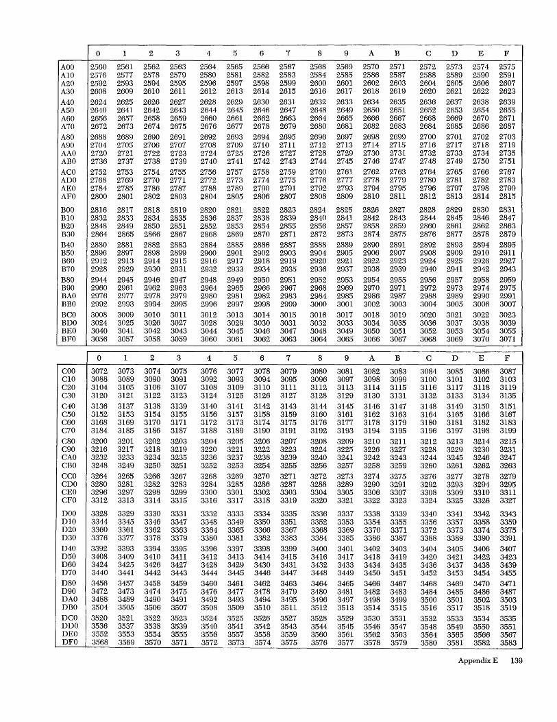
0 1 2 3 4 5 6 7 8 9 A B C D E F
AOO 2560 2561 2562 2563 2564 2565 2566 2567 2568 2569 2570 2571 2572 2573 2574 2575 A10 2576 2577 2578 2579 2580 2581 2582 2583 2584 2585 2586 2587 2588 2589 2590 2591 A20 2592 2593 2594 2595 2596 2597 2598 2599 2600 2601 2602 2603 2604 2605 2606 2607 A30 2608 2609 2610 2611 2612 2613 2614 2615 2616 2617 2618 2619 2620 2621 2622 2623 A40 2624 2625 2626 2627 2628 2629 2630 2631 2632 2633 2634 2635 2636 2637 2638 2639 A50 2640 2641 2642 2643 2644 2645 2646 2647 2648 2649 2650 2651 2652 2653 2654 2655 A60 2656 2657 2658 2659 2660 2661 2662 2663 2664 2665 2666 2667 2668 2669 2670 2671 A70 2672 2673 2674 2675 2676 2677 2678 2679 2680 2681 2682 2683 2684 2685 2686 2687 A80 2688 2689 2690 2691 2692 2693 2694 2695 2696 2697 2698 2699 2700 2701 2702 2703 A90 2704 2705 2706 2707 2708 2709 2710 2711 2712 2713 2714 2715 2716 2717 2718 2719 AAO 2720 2721 2722 2723 2724 2725 2726 2727 2728 2729 2730 2731 2732 2733 2734 2735 ABO 2736 2737 2738 2739 2740 2741 2742 2743 2744 2745 2746 2747 2748 2749 2750 2751 ACO 2752 2753 2754 2755 2756 2757 2758 2759 2760 2761 2762 2763 2764 2765 2766 2767 ADO 2768 2769 2770 2771 2772 2773 2774 2775 2776 2777 2778 2779 2780 2781 2782 2783 AEO 2784 2785 2786 2787 2788 2789 2790 2791 2792 2793 2794 2795 2796 2797 2798 2799 AFO 2800 2801 2802 2803 2804 2805 2806 2807 2808 2809 2810 2811 2812 2813 2814 2815
BOO 2816 2817 2818 2819 2820 2821 2822 2823 2824 2825 2826 2827 2828 2829 2830 2831 B10 2832 2833 2834 2835 2836 2837 2838 2839 2840 2841 2842 2843 2844 2845 2846 2847 B20 2848 2849 2850 2851 2852 2853 2854 2855 2856 2857 2858 2859 2860 2861 2862 2863 B30 2864 2865 2866 2867 2868 2869 2870 2871 2872 2873 2874 2875 2876 2877 2878 2879 B40 2880 2881 2882 2883 2884 2885 2886 2887 2888 2889 2890 2891 2892 2893 2894 2895 B50 2896 2897 2898 2899 2900 2901 2902 2903 2904 2905 2906 2907 2908 2909 2910 2911 B60 2912 2913 2914 2915 2916 2917 2918 2919 2920 2921 2922 2923 2924 2925 2926 2927 B70 2928 2929 2930 2931 2932 2933 2934 2935 2936 2937 2938 2939 2940 2941 2942 2943 B80 2944 2945 2946 2947 2948 2949 2950 2951 2952 2953 2954 2955 2956 2957 2958 2959 B90 2960 2961 2962 2963 2964 2965 2966 2967 2968 2969 2970 2971 2972 2973 2974 2975 BAO 2976' 2977 2978 2979 2980 2981 2982 2983 2984 2985 2986 2987 2988 2989 2990 2991 BBO 2992 2993 2994 2995 2996 2997 2998 2999 3000 3001 3002 3003 3004 3005 3006 3007 BCO 3008 3009 3010 3011 3012 3013 3014 3015 3016 3017 3018 3019 3020 3021 3022 3023 BDO 3024 3025 3026 3027 3028 3029 3030 3031 3032 3033 3034 3035 3036 3037 3038 3039 BEO 3040 3041 3042 3043 3044 3045 3046 3047 3048 3049 3050 3051 3052 3053 3054 3055 BFO 3056 3057 3058 3059 3060 3061 3062 3063 3064 3065 3066 3067 3068 3069 3070 3071
0 1 2 3 4 5 6 7 8 9 A B C D E F
COO 3072 3073 3074 3075 3076 3077 3078 3079 3080 3081 3082 3083 3084 3085 3086 3087 C10 3088 3089 3090 3091 3092 3093 3094 3095 3096 3097 3098 3099 3100 3101 3102 3103 C20 3104 3105 3106 3107 3108 3109 3110 3111 3112 3113 3114 3115 3116 3117 3118 3119 C30 3120 3121 3122 3123 3124 3125 3126 3127 3128 3129 3130 3131 3132 3133 3134 3135 C40 3136 3137 3138 3139 3140 3141 3142 3143 3144 3145 3146 3147 3148 3149 3150 3151 C50 3152 3153 3154 3155 3156 3157 3158 3159 3160 3161 3162 3163 3164 3165 3166 3167 C60 3168 3169 3170 3171 3172 3173 3174 3175 3176 3177 3178 3179 3180 3181 3182 3183 C70 3184 3185 3186 3187 3188 3189 3190 3191 3192 3193 3194 3195 3196 3197 3198 3199 C80 3200 3201 3202 3203 3204 3205 3206 3207 3208 3209 3210 3211 3212 3213 3214 3215 C90 3216 3217 3218 3219 3220 3221 3222 3223 3224 3225 3226 3227 3228 3229 3230 3231 CAO 3232 3233 3234 3235 3236 3237 3238 3239 3240 3241 3242 3243 3244 3245 3246 3247 CBO 3248 3249 3250 3251 3252 3253 3254 3255 3256 3257 3258 3259 3260 3261 3262 3263 CCO 3264 3265 3266 3267 3268 3269 3270 3271 3272 3273 3274 3275 3276 3277 3278 3279 CDO 3280 3281 3282 3283 3284 3285 3286 3287 3288 3289 3290 3291 3292 3293 3294 3295 CEO 3296 3297 3298 3299 3300 3301 3302 3303 3304 3305 3306 3307 3308 3309 3310 3311 CFO 3312 3313 3314 3315 3316 3317 3318 3319 3320 3321 3322 3323 3324 3325 3326 3327
DOO 3328 3329 3330 3331 3332 3333 3334 3335 3336 3337 3338 3339 3340 3341 3342 3343 D10 3344 3345 3346 3347 3348 3349 3350 3351 3352 3353 3354 3355 3356 3357 3358 3359 D20 3360 3361 3362 3363 3364 3365 3366 3367 3368 3369 3370 3371 3372 3373 3374 3375 D30 3376 3377 3378 3379 3380 3381 3382 3383 3384 3385 3386 3387 3388 3389 3390 3391 D40 3392 3393 3394 3395 3396 3397 3398 3399 3400 3401 3402 3403 3404 3405 3406 3407 D50 3408 3409 3410 3411 3412 3413 3414 3415 3416 3417 3418 3419 3420 3421 3422 3423 D60 3424 3425 3426 3427 3428 3429 3430 3431 3432 3433 3434 3435 3436 3437 3438 3439 D70 3440 3441 3442 3443 3444 3445 3446 3447 3448 3449 3450 3451 3452 3453 3454 3455 D80 3456 3457 3458 3459 3460 3461 3462 3463 3464 3465 3466 3467 3468 3469 3470 3471 D90 3472 3473 3474 3475 3476 3477 3478 3479 3480 3481 3482 3483 3484 3485 3486 3487 DAO 3488 3489 3490 3491 3492 3493 3494 3495 3496 3497 3498 3499 3500 3501 3502 3503 DBO 3504 3505 3506 3507 3508 3509 3510 3511 3512 3513 3514 3515 3516 3517 3518 3519 DCO 3520 3521 3522 3523 3524 3525 3526 3527 3528 3529 3530 3531 3532 3533 3534 3535 DDO 3536 3537 3538 3539 3540 3541 3542 3543 3544 3545 3546 3547 3548 3549 3550 3551 DEO 3552 3553 3554 3555 3556 3557 3558 3559 3560 3561 3562 3563 3564 3565 3566 3567 DFO 3568 3569 3570 3571 3572 3573 3574 3575 3576 3577 3578 3579 3580 3581 3582 3583
Appendix E 139

0 1 2 3 4 5 6 7 8 9 A B C D E F
EOO .3584 3585 3586 3587 3583 3589 3590 3591 3592 3593 3594 3595 3596 3597 3598 3599 E10 .3600 3601 3602 3603 3604 3605 3606 3607 3608 3609 3610 3611 3612 3613 3614 3615 E20 .3616 3617 3618 3619 3620 3621 3622 3623 3624 3625 3626 3627 3628 3629 3630 3631 E30 .3632 3633 3634 3635 3636 3637 3638 3639 3640 3641 3642 3643 3644 3645 3646 3647 E40 3648 3649 3650 3651 3652 3653 3654 3655 3656 3657 3658 3659 3660 3661 3662 3663 E50 .3664 3665 3666 3667 3668 3669 3670 3671 3672 3673 3674 3675 3676 3677 3678 3679 E60 3680 3681 3682 3683 3684 3685 3686 3687 3688 3689 3690 3691 3692 3693 3694 3695 E70 :3696 3697 3698 3699 3700 3701 3702 3703 3704 3705 3706 3707 3708 3709 3710 3711 E80 :3712 3713 3714 3715 3716 3717 3718 3719 3720 3721 3722 3723 3724 3725 3726 3727 E90 3728 3729 3730 3731 3732 3733 3734 3735 3736 3737 3738 3739 3740 3741 3742 3743 EAO :3744 3745 3746 3747 3748 3749 3750 3751 3752 3753 3754 3755 3756 3757 3758 3759 EBO 3760 3761 3762 3763 3764 3765 3766 3767 3768 3769 3770 3771 3772 3773 3774 3775 ECO :3776 3777 3778 3779 3780 3781 3782 3783 3784 3785 3786 3787 3788 3789 3790 3791 EDO :3792 3793 3794 3795 3796 3797 3798 3799 3800 3801 3802 3803 3804 3805 3806 3807 EEO 3808 3809 3810 3811 3812 3813 3814 3815 3816 3817 3818 3819 3820 3821 3822 3823 EFO :3824 3825 3826 3827 3828 3829 3830 3831 3832 3833 3834 3835 3836 3837 3838 3839
FOO :3840 3841 3842 3843 3844 3845 3846 3847 3848 3849 3850 3851 3852 3853 3854 3855 FlO :3856 3857 3858 3859 3860 3861 3862 3863 3864 3865 3866 3867 3868 3869 3870 3871 F20 :3872 3873 3874 3875 3876 3877 3878 3879 3880 3881 3882 3883 3884 3885 3886 3887 F30 3888 3889 3890 3891 3892 3893 3894 3895 3896 3897 3898 3899 3900 3901 3902 3903 F40 :3904 3905 3906 3907 3908 3909 3910 3911 3912 3913 3914 3915 3916 3917 3918 3919 F50 3920 3921 3922 3923 3924 3925 3926 3927 3928 3929 3930 3931 3932 3933 3934 3935 F60 3936 3937 3938 3939 3940 3941 3942 3943 3944 3945 3946 3947 3948 3949 3950 3951 F70 :3952 3953 3954 3955 3956 3957 3958 3959 3960 3961 3962 3963 3964 3965 3966 3967 F80 3968 3969 3970 3971 3972 3973 3974 3975 3976 3977 3978 3979 3980 3981 3982 3983 F90 :3984 3985 3986 3987 3988 3989 3990 3991 3992 3993 3994 3995 3996 3997 3998 3999 FAO 4000 4001 4002 4003 4004 4005 4006 4007 4008 4009 4010 4011 4012 4013 4014 4015 FEO 4016 4017 4018 4019 4020 4021 4022 4023 4024 4025 4026 4027 4028 4029 4030 4031 FCO 4032 4033 4034 4035 4036 4037 4038 4039 4040 4041 4042 4043 4044 4045 4046 4047 FDO 4048 4049 4050 4051 4052 4053 4054 4055 4056 4057 4058 4059 4060 4061 4062 4063 FEO 4064 4065 4066 4067 4068 4069 4070 4071 4072 4073 4074 4075 4076 4077 4078 4079 FFO 4080 4081 4082 4083 4084 4085 4086 4087 4088 4089 4090 4091 4092 4093 4094 4095
140
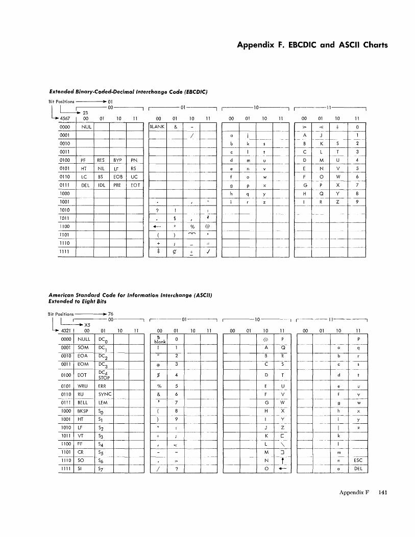
Extended Sinary-Coded-Decimal Interchange Code (EBCDIC)
Bit Positions ----.. ~ 01
L LJ:-2-3---00----'1 'I ----01----,
00 01 10 11 4567 00 01 10 11
0000 NUL BLANK & -0001 / .-
0010
0011
0100 PF RES BYP PN
0101 HT NL LF RS .-
0110 LC BS EOB UC
0111 DEL IDL PRE EOT
1000
1001 f " 1010 ? ! :
1011 $ f #
1100 +-- * % @
1101 ( ) r-.r'\ I
1110 + i - ==
1111 $ <7 + I -
American Standard Code for Information Interchange (ASCII) Extended to Eight Sits
Bit Positions ----... 76
L' 00 '-----..~ X5
4321 00 01 10 11
.-------01-----,
00 01 10 11
0000 NULL DCO '0 0 blank
0001 SOM DCl
! 1
0010 EOA DC2 " 2
0011 EOM DC3
3 --1---
=If --
0100 EOT DC4 STOP % 4
0101 WRU ERR % 5
0110 RU SYNC & 6
0111 BELL LEM ,
7
1000 BK5P 50 ( 8 --
1001 HT 51 ) 9
1010 LF 52 * : -'"--
1011 VT 53 + i
1100 FF 54 f "'" 1101 CR 55 - ==
1110 50 56 > --
1111 51 57 / ?
Appendix J:. EBCDIC and ASCII Charts
.------10---~ .-------11--------.
00 01 10 11 00 01 10 11
:> < :j: 0
a i --~--A J 1
-- _._-- r---b k B K S 2
c I C L T 3
d m u D M U 4 ----- - -
e n v E N V 5 ---
0 w F 0 W 6 ---
9 P x G P X 7 --
h q y H Q Y 8
z I R Z 9 -
-- -- -- .- --I--
f---- -----f---
~-_r---~-~---- --- ---- f---
--- ---
~_~ ___ L__~ ___ _
r------10---~ 11
00 01 10 11 00 01 10 11
@ P ""--- ---- ---- --
A Q a q
B R b --- ----- -----""- ---
C 5 c s r---- ----- ---
D T d t -
E U e u - --- ._-
F V v -----
G W 9 w
H X x
I Y y --
J Z i z
K [ k
L '\ -----
M :::J m
N .r- ------E5C
~- --0 '4--'- 0 DEL
Appendix F 141

Appendix G. Instructions
Data Formats
Fixed-Pount Numbers
Fullword Fixed-Point Number
Integer o 1 31
Hallword Fixed-Point Number
Integer o 1 15
Floating-Point Numbers
Short Floating-Point Number
IS I Characteristic I Fraction a 1 7 8 31
Long Floating-Point Number
I ~S~I~C __ ha_r_a_c_te_r_is_t_ic~I _________ F_r_a_c_ti_o_n ________ ~SS~ ______ ~ a 1 7 8 63
Decimal Numbers
Packed Decimal Number
I Digit I Digit I Digit [~~ ~~] Digit I Digit I Digit I Digit I Sign I
Zoned Decimal Number
I Zone I Digit I Zone [~- ~~] Digit I Zone I Digit I Sign I Digit I
Logical Information
Fixed-Length Logical Information
Logi cal Data
31
Variable-Length Logical Information
Character Character ~~] Character
16
142
Hexadecimal Representation HEXADECIMAL PRINTED EDCDIC~ Ascnt
CODE GRAPHIC CODE CODE
0000 0 11110000 01010000 0001 1 11110001 01010001 0010 2 11110010 01010010 0011 3 11110011 01010011 0100 4 11110100 01010100 0101 5 1111 0101 01010101 0110 6 1111 0110 01010110 0111 7 1111 0111 01010111 1000 8 11111000 01011000 1001 9 1111 1001 01011001 1010 A 11000001 1010 0001 1011 B 11000010 1010 0010 1100 C 11000011 1010 0011 1101 D 11000100 1010 0100 1110 E 11000101 1010 0101 1111 F 11000110 1010 0110
~Extended Binary-Coded-Decimal Interchange Code. tAn eight-bit representation for American Standard Code for Information Interchange for use in eight-bit environments.
Instructions by Format Type
RR Format
I Op Code R] R2 a 78 1112 15
Fixed Point
Load Load and Test Load Complement Load Positive Load Negative Add Add Logical Subtract Subtract Logical Compare Multiply Divide
Logical
Compare AND OR Exclusive OR
Branching
Branch on Condition Branch and Link Branch on Count
E E
1
Floating Point
Load S/L Load and Test S/L Load Complement S/L Load Positive S/L Load Negative S/L Add Normalized S/L Add Un normalized S/L Subtract Normalized S/L Subtract Unnormalized S/L Compare S/L Halve S/L Multiply S/L Divide S/L
Status Switching
Set Program Mask Supervisor Call Set Storage Key Insert Storage Key
2 3
Z Z

RX Format
o 7 8 11 1 2 15 16 1 9 20 31
Fixed Point
Load H/F Add H/F Add Logical Subtract H/F Subtract Logical Compare H/F Multiply H Multiply F Divide F Convert to Binary Convert to Decimal Store H/F
Logical
Compare Load Address Insert Character Store Character AND OR Exclusive OR
R5 Format
Op Code Rl 7 8
Fixed Point
Load Multiple Store Multiple Shift Left Single Shift Right Single Shift Left Double Shift Right Double
11 12
E E
2 2
E,2 E,2
1516
Floating Point
Load S/L Add Normalized S/L Add Unnormalized S/L Subtract Normalized S/L Subtract Unnormalized S/L Compare S/L Multiply S/L Store S/L Divide S/L
Branching
Branch on Condition Branch and Link Branch on Count Execute
1920
Logical
Shift Left Single Shift Right Single Shift Left Double Shift Right Double
Branching
Branch on High Branch on Low-Eq
1
31
2 2
E,2 E,2
51 Format
Op Code 12 --=r!l Dl ~
Input/Output
Start I/O Test I/O Halt I/O Test Channel
Logical
Move Compare AND OR
7 8
Exclusive OR Test Under Mask
55 Format
1516
4 4 4 4
1920 31
Status Switching
LoadPSW 4 Set System Mask 4 W rite Direct Y Read Direct Y Diagnose
~O~p_C_od_e~_L_l_~_L2~ __ Bl~IJ~?L_D~11 __ B2~11~ 7 8 11 12 1516 1920 31 32 35 36 47
Decimal Logical
Pack Move 5 Unpack Move Numeric 5 Move With Offset Move Zone 5 Zero and Add T Compare 5 Add T AND 5 Subtract T OR 5 Compare T Exclusive OR 5 Multiply T Translate 5 Divide T Translate and Test 5
Edit T,5 Edit and Mark T,5
FORMAT NOTES
E Rl must be even F Fullword H Halfword L Long S Short T Decimal feature Y Direct control feature Z Protection feature 1 Rl used as mask Ml 2 R2 or Ra ignored 3 Rl and R2 used as immediate information 4 12 ignored 5 Ll and L2 used as eight-bit L field
All floating-point instructions are part of the floating-point feature.
Appendix G 143
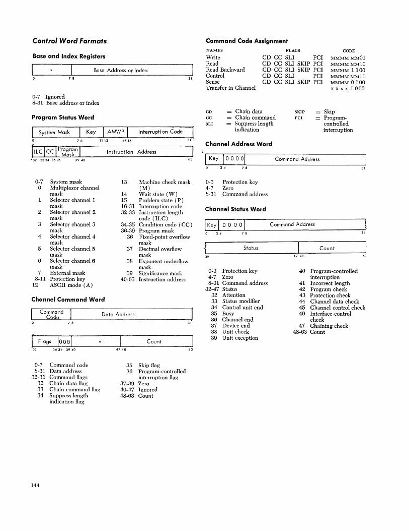
Control Word Formats
Base and ilndex Registers
* B.ase Address or Index
7 8 31
0-7 Ignored 8-31 Base address or index
Program Status Word
I System Mask Key I AMWP I Interruption Code
o 78 1112 1516 31
Instruction Address
32 33 34 35 36 39 40 63
0-7 System mask 13 Machine check mask 0 Multiplexor channel (M)
mask 14 Wait state (W) 1 Selector channel 1 15 Problem state (P)
mask 16-31 Interruption code 2 Selector channel 2 32-33 Instruction length
mask code (ILC) 3 Selector channel 3 34-35 Condition code (CC)
mask 36-39 Program mask 4 Selector channel 4 36 Fixed-point overflow
mask mask 5 Selector channel 5 37 Decimal overflow
mask mask 6 Selector channel 6 38 Exponent underflow
mask mask 7 External mask 39 Significance mask
8-11 Protection key 40-63 Instruction address 12 ASCII mode (A)
Channel Command Word
Command Data Address J Code 7 8 31
C Flags IOOO[ * Count
363:r 3940 4748 63
0-7 Command code 35 Skip flag 8-31 Data address 36 Program-controlled
32-36 Command flags interruption flag 32 Chain data flag 37-39 Zero 33 Chain command flag 40-47 Ignored 34 Suppress length 48-63 Count
indication flag
144
Command Code Assignment
FLAGS NAMES
Write Read Read Backward Control Sense
CD CC SLI PCI CD CC SLI SKIP PCI CD CC SLI SKIP PCI CD CC SLI PCI CD CC SLI SKIP PCI
CODE
MMMMMMOI MMMMMM10 MMMM 1100 MMMMMMll MMMM 0100 x x x x 1000 Transfer in Channel
CD CC SLI
Chain data Chain command Suppress length indication
Channel Address Word
SKIP
PCI
Skip Programcontrolled interruption
Ir-____ -, ____________ .-____________________________________________________________ ~
I Key [ 000 0 1 Command Address
34 7 8 31
0-3 Protection key 4-7 Zero 8-31 Command address
Channel Status Word
Command Address
34 7 8 31
Status Count
32 47 48 63
0-3 Protection key 40 Program-controlled 4-7 Zero interruption 8-31 Command address 41 Incorrect length
32-47 Status 42 Program check 32 Attention 43 Protection check 33 Status modifier 44 Channel data check 34 Control unit end 45 Channel control check 35 Busy 46 Interface· control 36 Channel end check 37 Device end 47 Chaining check 38 Unit check 48-63 Count 39 U nit exception
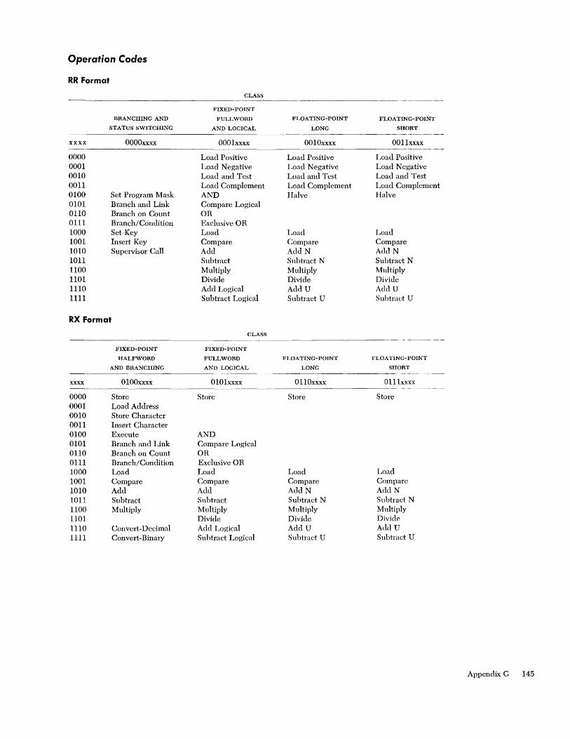
Operation Codes
RR Format
CLASS ------
FIXED-POINT
BRANCHING AND FULLWORD FLOATING-POINT FLOA TING-POINT
STATUS SWITCHING AND LOGICAL LONG SHORT -~--"-'"--
xxxx OOOOxxxx 0001xxxx 0010xxxx 0011xxxx
0000 Load Positive Load Positive Load Positive 0001 Load Negative Load Negative Load Negative 0010 Load and Test Load and Test Load and Test 0011 Load Complement Load Complement Load Complement 0100 Set Program Mask AND Halve Halve 0101 Branch and Link Compare Logical 0110 Branch on Co un t OR 0111 Branch/Condition Exclusive OR 1000 Set Key Load Load Load 1001 Insert Key Compare Compare Compare 1010 Supervisor Call Add Add N Add N 1011 Subtract Subtract N Subtract N 1100 Multiply Multiply Multiply 1101 Divide Divide Divide 1110 Add Logical Add U Add U 1111 Subtract Logical Subtract U Subtract U
RX Format
CLASS -- ------._--
FIXED-POINT FIXED-POINT
HALFWORD FULLWORD FLOA TING-POINT FLOATING-POINT
AND BRANCHING AND LOGICAL LONG SHORT --" -----~~-
xxxx 0100xxxx 010lxxxx 0110xxxx 011lxxxx -"-~----
0000 Store Store Store Store 0001 Load Address 0010 Store Character 0011 Insert Character 0100 Execute AND 0101 Branch and Link Compare Logical 0110 Branch on Count OR 0111 Branch/Condition Exclusive OR 1000 Load Load Load Load 1001 Compare Compare Compare Compare 1010 Add Add AddN AddN 1011 Subtract Subtract Subtract N Subtract N 1100 Multiply Multiply Multiply Multiply 1101 Divide Divide Divide 1110 Convert-Decimal Add Logical Add U AcM U 1111 Convert-Binary Subtract Logical Subtract U Subtract U
Appendix G 145

RS, SI FOl'mat
BRANCHING
STATUS SWITCHING
xxxx
0000 0001 0010 0011 0100 0101 0110 0111 1000 1001 1010 1011 1100 1101 1110 1111
SS Format
xxxx
0000 0001 0010 0011 0100 0101 0110 0111 1000 1001 1010 1011 1100 1101 lll0 llll
AND SHIFTING
1000xxxx
Set System Mask
Load PSW Diagnose Write Direct Read Direct Branch/High Branch/Low-Equal Shift Right SL Shift Left SL Shift Right S Shift Left S Shift Right DL Shift Left DL Shift Right D Shift Left D
1100xxxx
OPERATION CODE NOTES
N Normalized SL Single logical DL Double logical
146
U S D
CLASS
FIXED-POINT
LOGICAL AND
INPUT/OUTPUT
100lxxxx
Store Multiple Test Under Mask Move
AND Compare Logical OR Exclusive OR Load Multiple
Start I/O Test I/O Halt I/O Test Channel
CLASS
LOGICAL
1l01xxxx
Move Numeric Move Move Zone AND Compare Logical OR Exclusive OR
Translate Translate and Test Edit Edit and Mark
U nnormalized Single Double
1010xxxx
1110xxxx
10llxxxx
DECIMAL
llllxxxx
Move With Offset Paek Unpack
Zero and Add Compare Add Subtract Multiply Divide

Permanent Storage Assignment ADDRESS LENGTH PURPOSE
o 0000 0000 double-word Initial program loading PSW 8 0000 1000 double-word Initial program loading CCW 1
16 0001 0000 double-word Initial program loading CCW2 24 00011000 double-word External old PSW 32 0010 0000 double-word Supervisor call old PSW 40 0010 1000 double-word Program old PSW 48 0011 0000 double-word Machine-check old PSW 56 0011 1000 double-word Input/output old PSW 64 01000000 double-word Channel status word 72 01001000 word Channel address word 76 0100 1100 word Unused 80 0101 0000 word Timer 84 0101 0100 word Unused 88 0101 1000 double-word External new PSW 96 01100000 double-word Supervisor call new PSW
104 0110 1000 double-word Program new PSW 112 01110000 double-word Machine-check new PSW 120 0111 1000 double-word Input/output new PSW 128 1000 0000 Diagnostic scan-out area 0
o The size of the diagnostic scan-out area depends on the particular model and I/O channels.
Condition Code Setting
Fixed-Point Arithmetic
0 1 2 3 AddH/F zero < zero > zero overflow Add Logical zero not zero zero, carry
carry Compare H/F equal low high Load and Test zero < zero > zero Load Complement zero < zero > zero overflow Load Negative zero < zero Load Positive zero > zero overflow Shift Left Double zero < zero > zero overflow Shift Left Single zero < zero > zero overflow Shift Right Double zero < zero > zero Shift Right Single zero < zero > zero Subtract H/F zero < zero > zero overflow Subtract Logical not zero zero, carry
carry
Decimal Arithmetic
Add Decimal zero < zero > zero overflow Compare Decimal equal low high Subtract Decimal zero < zero > zero overflow Zero and Add zero < zero > zero overflow
Floating-Point Arithmetic
Add Normalized S/L zero < zero > zero overflow Add Unnormalized S/L zero < zero > zero overflow Compare S/L equal low high Load and Test S/L zero < zero > zero
Load Complement S/L zero < zero > zero Load Negative S/L zero < zero Load Positive S/L zero > zero Subtract
Normalized S/L zero < zero > zero overflow Subtract Unnorm-
alized S/L zero < zero > zero overflow
Logical Operaticlns
AND zero not zero Compare Logical equal low high Edit zero < zero > zero Edit and Mark zero < zero > zero Exclusive OR zero not zero OR zero not zero Test Under Mask zero mixed one Translate and Test zero incomplete complete
Input / Output Oillerations
Halt I/O not halted stopped not oper working
Start I/O available CSW busy not oper stored
Test Channel not CSW working not oper working ready
Test I/O available CSW working not oper stored
CONDITION CODE SETTING NOTES
available Unit and channel available busy Unit or chanel busy carry A carry out of the sign position occurred complete Last result byte nonzero CSW ready Channel status word ready for test or interruption CSW stored Channel status word stored equal Ope:rands compare equal F Fullword > zero Result is greater than zero H Halfword halted Data transmission stopped. Unit in halt-reset mode high First operand compares high incomplete Nonzero result byte; not last L Long precision < zero Result is less than zero low First operand compares low mixed Selected bits are both zero and one not opel' Unit or channel not operational not working Unit or channel not working not zero Result is not all zero one Selected bits are one overflow Result overflows S Short precision stopped Data transmission stopped working Unit or channel working zero Result or selected bits are zero The condition code also may be changed by LOAD PSW, SET SYSTEM MASK, DIAGNOSE, and by an interruption.
Appendix G 147
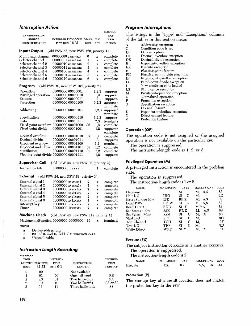
Interruption Action INSTRUC
TION INTERRUPTION
SOURCE
IDENTIFICATION
INTERRUPTION CODE MASK ILC EXE-
PSW BITS 16-31 BITS SET CUTION
Input / Output ( old PSW 56, new PSW 120, priority 4)
Multiplexor channel 00000000 aaaaaaaa 0 x complete Selector channell 00000001 aaaaaaaa 1 x complete Selector channel 2 00000010 aaaaaaaa 2 x complete Selector channel 3 00000011 aaaaaaaa 3 x complete Selector channcl4 00000100 aaaaaaaa 4 x complete Selector channel 5 00000101 aaaaaaaa 5 x complete Selector channel 6 00000110 aaaaaaaa 6 x complete
Program ( old PSW 40, new PSW 104, priority 2)
Operation 00000000 00000001 1,2,3 suppress Privileged operation 00000000 00000010 1,2 suppress Execute 00000000 00000011 2 suppress Protection 00000000 00000100 0,2,3 suppress/
terminate Addressing 00000000 00000101 1,2,3 suppress/
terminate Specification 00000000 00000110 1,2,3 suppress Data 00000000 00000 III 2,3 terminate Fixed-point overflow 0000000000001000 36 1,2 complete Fixed-point divide 0000000000001001 1,2 suppress/
complete Decimal overflow 00000000 00001 0 1 0 37 3 complete Decimal divide 00000000 00001011 3 suppress Exponent overflow 00000000 00001100 1,2 terminate Exponent underflow 00000000 00001101 38 1,2 complete Significance 00000000 0000 III 0 39 1,2 complete Floating-point divide 0000000000001111 1,2 suppress
Supervisol' Call ( old PSW 32, new PSW 96, priority 2)
Instruction bits 00000000 r r r r r r r r 1 complete
External ( old PSW 24, new PSW 88, priority 3 )
External signal 1 00000000 xxxxxxxi 7 x complete External signal 2 00000000 xxxxxx1x 7 x complete External signal 3 00000000 xxxxx1xx 7 x complete External signal 4 00000000 xxxx1xxx 7 x complete External signal 5 00000000 xxxlxxxx 7 x complete External signal 6 00000000 xx1xxxxx 7 x complete Interrupt key 00000000 xlxxxxxx 7 x complete Timer 00000000 lxxxxxxx 7 x complete
Machine Check (old PSW 48, new PSW 112, priority 1)
Machine malfunction 00000000 00000000 13 x terminate
NOTES
a r x
Device address bits Bits of Rl and R2 field of SUPERVISOR CALL
Unpredictable
Instruction Length Recording INSTRUC-
TION INSTRUC-
I,ENGTH PEW BITS TION INSTRUCTION
CODE ~~2-33 BITS 0-1 LENGTH
0 00 Not available 1 01 00 One halfword 2 10 01 Two halfwords 2 10 10 Two halfwords 3 11 11 Three halfwords
148
INSTRUC-
TION
FORMAT
RR RX
RS or SI SS
Program Interruptions The listings in the "Type" and "Exceptions" columns of the tables in this section mean: A Addressing exception C Condition code is set D Data exception DF Decimal-overflow exception DK Decimal-divide exception E Exponent-overflow exception EX Execute exception F Floating-point feature FK Floating-point divide exception IF Fixed-point overflow exception IK Fixed-point divide exception L New condition code loaded LS Significance exception M Privileged-operation exception N Normalized operation P Protection exception S Specification exception T Decimal feature U Exponent-underflow exception Y Direct control feature Z Protection feature
Operation (OP)
The operation code is not assigned or the assigned operation is not available on the particular cpu.
The operation is suppressed. The instruction-length code is 1, 2, or 3.
Privileged Operation (M)
A privileged instruction is encountered in the problem state.
The operation is suppressed. The instruction-length code is 1 or 2.
NAME MNEMONIC TYPE EXCEPTIONS CODE
Diagnose SI M, A,S 83 Halt 110 IIIO SI C M, 9E Insert Storage Key ISK RRZ M, A,S 09 Load PSW LPSW SI L M, A,S 82 Head Direct RDD SI Y M,P,A 85 Sct Storage Key SSK RRZ M, A,S 08 Set System Mask SSM SI C M, A 80 Start 110 SIO SI C M, 9C Test Channel TCH SI C M, 9F Test 110 TIO SI C M, 9D Writc Direct WRD SI Y M, A 84
Execute (EX)
The subject instruction of EXECUTE is another EXECUTE.
The operation is suppressed. The instruction-length code is 2.
NAME
Execute
Protection (P)
MNEMONIC
EX TYPE
RX EXCEPTIONS CODE
A,S, EX 44
The storage key of a result location does not match the protection key in the psw.

The operation is suppressed, except in the case of NAME MNEMONIC TYPE EXCEPTIONS CODE NOTE
STORE MULTIPLE, READ DIRECT, and variable-length op- AND NI SI C P,A, 94 SPR
erations, which are terminated. AND NC SS C P,A D4 TRM
The instruction-length code is 0, 2, or 3. Compare C RX C A,S, 59 TRM Compare
NAME MNEMONIC TYPE EXCEPTIONS CODE NOTE Decimal CP SS T,C A, D F9 TRM
Add Decimal AP SS T,C P,A, D, DF FA TRM Compare
AND NI SI C P,A 94 SPR Halfword CH RX C A,S, 49 TRM
AND NC SS C P,A D4 TRM Compare
Convert to Logical CL RX C A,S, 55 TRM
Decimal CVD RX P,A,S 4E SPR Compare
Divide Decimal DP SS T P,A,S,D, DK FD TRM Logical CLI SI C A 95 TRM
Edit ED SS T,C P,A, D DE TRM Compare
Edit: and Mark EDMK SS T,C P,A, D DF TRM Logical CLC SS C A D5 TRM
Exclusive OR XI SI C P,A 97 SPR Compare (Long) CD RXF,C A,S, 69 TRM
Exclusive OR XC SS C P,A D7 TRM Compare (Short) CE RXF,C A,S, 79 TRM
Move MVI SI P,A 92 SPR Convert to
Move MVC SS P,A D2 TRM Binary CVB RX A,S,D, IK 4F TRM
Move Numerics MVN SS P,A D1 TRM Convert to
Move with Decimal CVD RX P,A,S, 4E SPR
Offset MVO SS P,A F1 TRM Diagnose SI M, A,S, 83 SPR Move Zones MVZ SS P,A D3 TRM Divide D RX A,S, IK 5D TRM Multiply Divide Decimal DP SS T P,A,S,D, DK FO TRM
Decimal MP SS T P,A,S,D FC TRM Divide (Long) NDD RXF A,S,U,E,FK 60 TRM OR 01 SI C P,A 96 SPR Divide (Short) NDE RXF A,S,U,E,FK 70 THM OR OC SS C P,A D6 TRM Edit ED SS T,C P,A, D DE TRM Pack PACK SS P,A F2 TRM Edit and Mark EDMK SS T,C P,A, D DF TRM Read Direct RDD SI Y M,P,A 85 TRM Exclusive OR X RX C A,S, 57 TRM Store ST RX P,A,S 50 SPR Exclusive OR XI SI C P,A, 97 SPR Store Character STC RX P,A 42 SPR Exclusive OR XC SS C P,A, D7 TRM Store Halfword STH RX P,A,S 40 SPR Execute EX RX A,S, EX 44 SPR Store Long STD RXF P,A,S 60 SPR Insert Character IC RX A 43 TRM Store Insert Storage
Multiple STM RXF P,A,S 90 TRM Key ISK RRZ M, A,S 09 Store Short STE RXF P,A,S 70 SPR Subtract Load L RX A,S, 58 TRM
Decimal SP SS T,C P,A, D, DF FB TRM Load Halfword LH RX A,S, 48 TRM
Translate TR SS P,A DC TRM Load (Long) LD RXF A,S, 68 TRM
Unpack UNPK SS P,A F3 TRM Load Multiple LM RS A,S, 98 TRM
Zero and Add ZAP SS T,C P,A, D, DF F8 TRM Load PSW LPSW SI LM, A,S 82 TRM Load (Short) LE RXF A,S, 78 TRM
PROTECTION INTERRUPTION NOTES Move MVI SI P,A 92 SPR SPR = Operation suppressed Move MVC SS P,A D2 TRM TRM = Operation terminated Move Numerics MVN SS P,A D1 TRM
Addressing (A) Move with Offset MVO SS P,A Fl TRM Move Zones MVZ SS P,A D3 TRM
An address specifies any part of data, instructions, or Multiply M RX A,S 5C TRM
control words outside the available storage for the par- Multiply
ticular installation. Decimal MP SS T P,A,S,D FCTRM
Multiply The operation is terminated. Data in storage remain IIalfword MH RX A,S 4C TUM
unchanged, except when designated by valid ad- Multiply (Long) NMD RXF A,S,U,E 6C -;"'RM
dresses. Multiply (Short) NME RXF A,S,U,E 7C TUM
The instruction-length code normally is 2 or 3; but OR 0 RX C A,S, 56 TRM OR 01 SI C P,A 96 SPR
may be 0, in the case of a data address. OR OC SS C P,A D6 TRM
NAME MNEMONIC TYPE EXCEPTIONS CODE NOTE Pack PACK SS P,A F2 TRM
Add A RX C A,S, IF 5A TRM Read Direct RDD SI Y M,P,A, 85 TRM
Add Decimal AP SS T,C P,A D, DF FA TRM Set Storage Key SSK RRZ M, A,S 08 Add Halfword AH RX C A,S, IF 4A TRM Set System Mask SSM SI M, A 80 TRM Add Logical AL RX C A,S, 5E TRM Store ST RX P,A,S 50 SPR Add Normalized Store Character STC RX P,A 42 SPR
(Long) NAD RXF,C A,S,U,E,LS 6A TRM Store Halfword STH RX P,A,S 40 SPR Add Normalized Store (Long) STD RXF P,A,S 60 SPR
( Short) NAE RXF,C A,S,U,E,LS 7A TRM Store Multiple STM RS P,A,S 90 TRM Add Unnorm- Store (Short) STE RXF P,A,S 70 SPR
alized (Long) AW RXF,C A,S, E,LS 6E TRM Subtract S RX C A,S, IF 5B TRM Add Unnorm- Subtract Decimal SP SS T,C P,A, D, DF FB TRM
alized (Short) AU RXF,C A,S, E,LS 7E TRM Subtract AND N RX C A,S, 54 TRM Halfword SH RX C A,S, IF 4B TRM
Appendix G 149

NAME MNEMONIC TYPE
Subtract Logical SL RX C Subtract Norm-
alized (Long) N SD RX F,C Subtract Norm-
alized (Short) N SE RX F,C Subtract Un-
normalized (Long)
Subtract Unnormalized ( Short)
Test Under Mask Translate Translate and
Test
SW RX F,C
SU RX F,C
TM SI C TR SS
TRT SS C
UNPK SS
EXCEPTIONS CODE NOTE
A,S 5F TRM
A,S,U,E,LS 6B TRM
A,S,U,E,LS 7B TRM
A,S, E,LS 6F TRM
A,S, E,LS 7F TRM
A 91 TRM P,A DC TRM
A DDTRM
P,A F3 TRM Unpack
Write Direct
Zero and Add 'VRD SI Y M, A 84 TRM
ZAP SS T,C P,A, D, DF F8 TRM
The addressing interruption can occur in normal sequential operation following branching, LOAD PSW, interruption, or manual operation.
Instruction execution is suppressed.
ADDRESSING INTERRUPTION NOTES
SPR Operation suppressed TRM = Operation terminated
Specification (S)
1. A data, instruction, or control-word address does not specify an integral boundary for the unit of information.
2. The Rl field of an instruction specifies an odd register address for a pair of general registers that contain a 64-bit operand.
3. A floating-point register address other than 0, 2, 4, or 6 is specified.
4. The multiplier or divisor in decimal arithmetic exceeds 15 digits and sign.
5. The first operand field is shorter than or equal to the second operand field in decimal multiplication or division.
6. The block address specified in SET STORAGE KEY
or INSERT STORAGE KEY has the four low-order bits not all zero.
7. A psw with nonzero protection key is loaded when the protection feature is not installed.
In all of these cases the operation is suppressed. The instruction-length code is 1, 2, or 3.
NAME MNEMONIC
Add A Add Halfword AH Add Logical AL Add Normalized
(Long) N ADR Add Normalized
(Long) N AD Add Normalized
( Short) N AER Add NormaHzed
(Short) N AE
150
TYPE
RX C RX C RX C
RRF,C
RXF,C
RRF,C
RXF,C
EXCEPTIONS
A,S, A,S, A,S
CODE NOTE
IF 5A 4 IF 4A 2
5E 4
S,U,E,LS 2A 3
A,S,U,E,LS 6A 3,8
S,U,E,LS 3A 3
A,S,U,E,LS 7A 3,4
NAME
Add Unnormalized (Long)
Add Unnormalizcd (Long)
Add Un normalized (Short)
Add Unnormalized (Short)
AND
Compare Compare
I Ialfword Compare
Logical Compare
(Long) Compare
(Long) Compare
( Short) Compare
( Short) Convert to
Binary Convert to
Decimal
Diagnose Divide Divide Divide Dccimal Dividc (Long) Divide (Long) Divide (Short) Divide (Short)
Exclusive OB Execute
Halve (Long) Halve (Short)
Insert Storage Key
Load Load and Test
(Long) I,oad and T(~st
(Short) Load Comple
ment (Long) Load Comple-
ment (Short) Load Halfword Load (Long) I,oad (Long) r,oad
Multiple Load Negative
( Long) Load Negative
(Short) Load Positive
(Long) T ,oad Positive
(Short) Load PSW Load (Short) Load (Short)
Multiply Multiply
MNEMONIC
AWR
AW
AUR
AU N
C
CH
CL
CDR
CD
CER
CE
CVB
CVD
DR D DP
NDDR NDD NDER NDE
X EX
HDR HER
ISK L
LTDR
LTER
LCDR
LCER LH LDR LD
LM
LNDR
LNER
LPDR
LPER LPS\V LER LE
MR M
TYPE EXCEPTIONS CODE NOTE
RRF,C
RX,F,C
RRF,C
RXF,C RX C
RX C
RX C
RX C
RR,F,C
RX,F,C
RR,F,C
RX,F,C
S, E,LS 2E 3
A,S, E,LS 6E 3,8
S, E,LS 3E 3
A,S, E,LS 7E 3,4 A,S 54 4
A,S
A,S
A,S
S
A,S
S
A,S
59 4
49 2
55 4
29 3
69 3,8
39 3
79 3,4
RX A,S,D, IK 4F 8
RX
SI RR RX SS T RRF RXF RRF RXF
RX C RX
RRF RRF
P,A,S 4E 8
M, A,S 83 S, IK ID 1
A,S, IK 5D 1,4 P,A,S,D, DK FD 5
S,U,E,FK 2D 3 A,S, U ,E,FK 6D 3,8
S,U,E,FK 3D 3 A,S,U,E,FK 7D 3,4
A,S 57 4 A,S, EX 44 2
S 24 3 S 34 3
RRZ M, A,S 09 7 RX A,S
RR F,C S
RR F,C S
RR F,C S
RRF,C RX RRF RXF
RS
RRF,C
RRF,C
RRF,C
S A,S
S A,S
A,S
S
S
S
RR F,C S SI L M, A,S RRF S RX FA,S
RR RX
S A,S
58 4
22 3
32 3
23 3
33 3 48 2 28 3 68 3,8
98 4
21 3
31 3
20 3
30 3 82 6,8 38 3 78 3,4
lC 1 5C 1,4

NAME MNEMONIC TYPE EXCEPTIONS CODE NOTE
Multiply Decimal MP SS T P,A,S,D FC 5
Multiply Halfword MH RX A,S 4C 2
Multiply (Long) N MDR RRF S,U,E 2C 3 Multiply (Long) N MD RXF A,S,U,E 6C 3,8 Multiply (Short) N MER RRF S,U,E 3C 3 Multiply (Short) N ME RXF A,S,U,E 7C 3,4
OR 0 RX C A,S 56 4
Set Storage Key SSK RRZ M, A,S 08 7
Shift Left Double SLDA RS C S, IF 8F 1
Shift Left Double Logical SLDL RS S 8D 1
Shift Right Double SRDA RS C S 8E 1
Shift Right Double Logical SRDL RS S 8C 1
Store ST RX P,A,S 50 4 Store IIalfword STH RX P,A,S 40 2 Store (Long) STD RXF P,A,S 60 3,8 Store Multiple STM RS P,A,S 90 4 Store (Short) STE RXF P,A,S 70 3,4 Subtract S RX C A,S, IF 5B 4 Subtract
Halfword SH RX C A,S, IF 4B 2 Subtract
Logical SL RX C A,S 5F 4 Subtract Norm-
alized (Long) NSDR RRF,C S,U,E,LS 2B 3 Subtract Norm-
alized (Long) NSD RXF,C A,S,U,E,LS 6B 3,8 Subtract Norm-
alized (Short) NSER RRF,C S,U,E,LS 3B 3 Subtract Norm-
alized (Short) NSE RXF,C A,S,U,E,LS 7B 3,4 Subtract Un-
normalized (Long)
Subtract Un-SWR RRF,C S, E,LS 2F 3
normalized (Long) SW RXF,C A,S, E,LS 6F 3,8
Subtract Un-normalized ( Short) SUR RRF,C S, E,LS 3F 3
Subtract Un-normalized ( Short) SU RXF,C A,S, E,LS 7F 3,4
The spccification interruption can occur in normal sequential operation following branching, LOAD psw, intcrruption, or man-ual operation (Note 1). The spccification interruption can occur during an interruption (Note 6).
SPECIFICATION INTEnnUPTION NOTES
1 Even register spccification 2 Two-byte unit of information specification 3 Floating-point register specification 4 Four-bytc unit of information specification 5 Decimal multiplier or divisor size specification 6 Zero protection key specification 7 Block address specification 8 Eight-byte unit of information specification
Data (D)
1. The sign or digit codes of operands in decimal arithmetic, or editing operations, or CONVERT TO
BINARY, are incorrect. 2. Fields in decimal arithmetic overlap incorrectly. 3. The decimal multiplicand has too many high
order significant digits. The operation is terminated in all three cases. The instruction-length code is 2 or 3.
NAME MNEMONIC TYPE EXCEPTIONS CODE NOTE
Add Decimal AP SST,C P,A, D, DF FA 1 Compare
Decimal CP SS T,C A, D F9 1 Convert to
Binary CVB RX A,S,D IK 4F Divide Decimal DP SS T P,A,S,D, DK FD 1 Edit ED SS T,C P,A, D DE Edit and Mark EDMK SS T,C P,A, D DF Multiply
Decimal MP SS T P,A,S,D FC 1,2 Subtract
Decimal SP SS T,C P,A, D, DF FB 1 Zero and Add ZAP SS T,C P,A, D, DF F8 1
All instructions listed may have incorrect codes.
DATA INTEHRUPTION NOTES
1 Overlapping fields 2 Multiplicand length
Fixed-Point Overflow (IF)
A high-order carry occurs or high-order significant bits are lost in fixed-point addition, subtraction, shifting, or sign-control operations.
The operation is completed by ignoring the information placed outside the register. The interruption may be masked by psw bit 36.
The instruction-length code is 1 or 2.
NAME MNEMONIC TYPE EXCEPTIONS CODE
Add AR RR C IF 1A Add A RX C A,S, IF 5A Add Halfword AH RX C A,S, IF 4A Load Complement LCR RR C IF 13 Load Positive LPH RR C IF 10 Shift Left Double SLDA RS C S, IF 8F Shift Left Single SLA RS C IF 8B Subtract SR RR C IF IB Subtract S RX C A,S, IF 5B Subtract Halfword SH RX C A,S, IF 4B
Fixed-Point Divide (IK)
1. The quotient exceeds the register size in fixedpoint division, including division by zero.
2. The result of CONVERT TO BINARY exceeds 31 bits. Division is suppressed. Conversion is completed by
ignoring the information placed outside the register. The instruction -length code is 1 or 2.
NAME MNEMONIC TYPE EXCEPTIONS CODE
Convert to Binary CVB RX A,S,D, IK 4F Divide DR RR S, IK ID Dividc D RX A,S, IK 5D
Appendix G 151
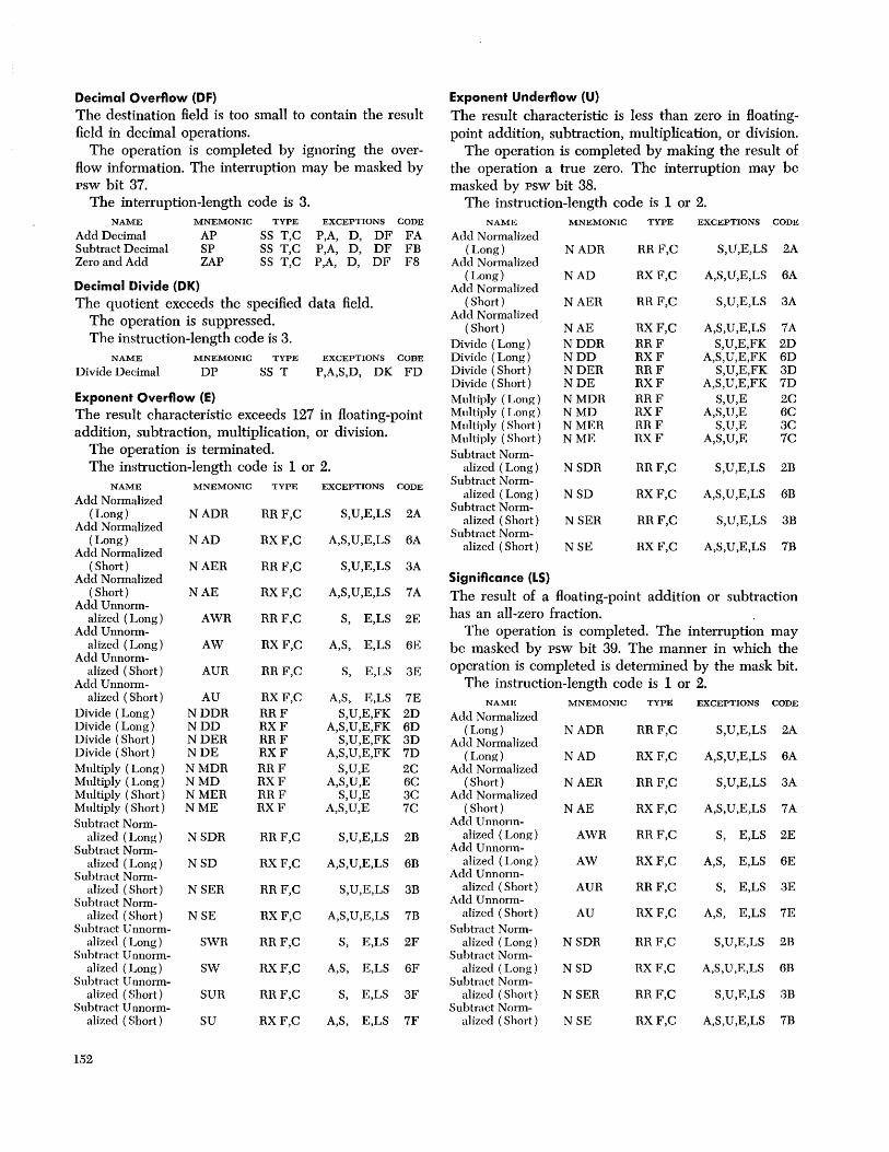
Decimal Overflow (OF) Exponent Underflow (U) The destination field is too small to contain the result The result characteristic is less than zero in floating-field in decimal operations. point addition, subtraction, multiplication, or division.
The operation is completed by ignoring the over- The operation is completed by making the result of flow information. The interruption may be masked by the operation a true zero. The interruption may be psw bit 37. masked by psw bit 38.
The interruption-length code is 3. The instruction-length code is 1 or 2. NAME MNEMONIC TYPE EXCEPTIONS CODE NAME MNEMONIC TYPE EXCEPTIONS CODE
Add Decimal AP SS T,C P,A, D, DF FA Add Normalized Subtract Decimal SP SS T,C P,A, D, DF FB (Long) NADR RRF,C S,U,E,LS 2A Zero and Add ZAP SS T,C P,A, D, DF F8 Add Normalized
( Long) NAD RXF,C A,S,U,E,LS 6A Decimal [)ivide (OK) Add Normalized The quotient exceeds the specified data field. (Short) NAER RRF,C S,U,E,LS 3A
The operation is suppressed. Add Normalized ( Short) NAE RXF,C A,S,U,E,LS 7A
The instruction-length code is 3. Divide (Long) NDDR RRF S,U,E,FK 2D NAME MNEMONIC TYPE EXCEPTIONS CODE Divide (Long) NDD RXF A,S,U,E,FK 6D
Divide Decimal DP SS T P,A,S,D, DK FD Divide (Short) NDER RRF S,U,E,FK 3D Divide (Short) NDE RXF A,S,U,E,FK 7D
Exponent Overflow (E) Multiply (Long) NMDR RRF S,U,E 2C The result characteristic exceeds 127 in floating-point Multiply (Long) NMD RXF A,S,U,E 6C
addition, subtraction, multiplication, or division. Multiply (Short) NMER RRF S,U,E 3C Multiply (Short) NME RXF A,S,U,E 7C
The operation is terminated. Subtract Norm-The instruction-length code is 1 or 2. alizcd (Long) NSDR RRF,C S,U,E,LS 2B
NAME MNEMONIC TYPE EXCEPTIONS CODE Subtract Norm-
Add Normalized alized (Long) NSD RXF,C A,S,U,E,LS 6B
(Long) NADR RRF,C S,U,E,LS 2A Subtract Norm-
Add Normalized alized (Short) NSER RRF,C S,U,E,LS 3B
(Long) NAD RXF,C A,S,U,E,LS 6A Subtract Norm-
Add Normalized alizcd (Short) NSE RXF,C A,S,U,E,LS 7B
( Short) NAER RRF,C S,U,E,LS 3A Add Normalized Significance (LS)
( Short) NAE RXF,C A,S,U,E,LS 7A The result of a floating-point addition or subtraction Add Unnorm-
alized (Long) AWR RRF,C S, E,LS 2E has an all-zero fraction. Add UnnOIm- The operation is completed. The interruption may
alized (Long) AW RXF,C A,S, E,LS 6E be masked by psw bit 39. The manner in which the Add Unnorm-
alized (Short) AUR RRF,C S, E,LS 3E operation is completed is determined by the mask bit. Add Unnorm- The instruction-length code is 1 or 2.
alized (Short) AU RXF,C A,S, E,LS 7E NAME MNEMONIC TYPE EXCEPTIONS CODE Divide (Long) NDDR RRF S,U,E,FK 2D Add Normalized Divide (Long) NDD RXF A,S,U,E,FK 6D ( Long) NADR RRF,C S,U,E,LS 2A Divide (Short) NDER RRF S,U,E,FK 3D Add Normalized Divide (Short) NDE RXF A,S,U,E,FK 7D (Long) NAD RXF,C A,S,U,E,LS 6A Multiply (Long) NMDR RRF S,U,E 2C Add Normalized Multiply (Long) NMD RXF A,S,U,E 6C (Short) NAER RRF,C S,U,E,LS 3A Multiply (Short) NMER RRF S,U,E 3C Add Normalized Multiply (Short) NME RXF A,S,U,E 7C ( Short) NAE RXF,C A,S,U,E,LS 7A Subtract Norm- Add Unnorm-
alized (Long) NSDR RRF,C S,U,E,LS 2B alizcd (Long) AWR RRF,C S, E,LS 2E Subtract Norm- Add Unnonn-
alizcd (Long) NSD RXF,C A,S,U,E,LS 6B alized (Long) AW RXF,C A,S, E,LS 6E Subtract Norm- Add Unnonn-
alized (Short) NSER RRF,C S,U,E,LS 3B alizcd (Short) AUR RRF,C S, E,LS 3E Subtract Norm- Add Unnorm-
alizcd (Short) NSE RXF,C A,S,U,E,LS 7B alizcd (Short) AU RXF,C A,S, E,LS 7E Subtract U nnorm- Subtract Norm-
alized (Long) SWR RRF,C S, E,LS 2F alizcd (Long) NSDR RRF,C S,U,E,LS 2B Subtract Unnorm- Subtract Norm-
alized (Long) SW RXF,C A,S, E,LS 6F alizcd (Long) NSD RXF,C A,S,U,E,LS 6D Subtract Un norm- Subtract Norm-
alized (Short) SUR RRF,C S, E,LS 3F alizcd (Short) NSER RRF,C S,U,E,LS 3B Subtract Unnorm- Subtract Norm-
alized (Short) SU RXF,C A,S, E,LS 7F aHzcd (Short) NSE RXF,C A,S,U,E,LS 7B
152

NAME MNEMONIC TYPE EXCEPTIONS CODE
Subtract Unnorm-alized (Long) SWR RRF,C S, E,LS 2F
Subtract Unnorm-alized (Long) SW RXF,C A,S, E,LS 6F
Subtract Un norm-alized (Short) SUR RRF,C S, E,LS 3F
Subtract Unnorm-alized (Short) SU RXF,C A,S, E,LS 7F
Floating-Point Divide (FK)
Division by a floating-point number with zero fraction is attempted.
The operation is suppressed. The instruction-length code is 1 or 2.
NAME MNEMONIC TYPE EXCEPTIONS
Divide (Long) NDDR RRF S,U,E,FK Divide (Long) NDD RXF A,S,U,E,FK Divide (Short) NDER RRF S,U,E,FK Divide (Short) NDE RXF A,S,U,E,FK
Editing CHAR- EXAM- TRlG- RESULT
ACTER NAME AND INE GER DIGIT CHAR-
CODE PURPOSE DIGIT STATUS STATUS ACTER
00100000 digit select yes s=1 digit s=o d not 0 digit s=O d=O fill
00100001 significance yes s=1 digit start s=O d not 0 digit
s=O d=O fill 0010 0010 field no fill
separator other message no s=1 leave
insertion s=O fill NOTES
d Source digit
CODE
2D 6D 3D 7D
TRIG
GER
SET
S trigger (1: minus sign, digits, or pattern used; 0: plus sign, fill used)
digit fill leave other
A source digit replaces the pattern character. The fill character replaces the pattern character. The pattern character remains unchanged. Any other pattern character.
Timer 111111111 23 24 25 26 27 28 29 30 31
System Control Panel
Operator Controls
NAME
Emergency Pull Power On Power Off Interrupt Wait Manual System Test Load Load Unit Load Prefix Select>O
>0 Multisystem feature
IMPLEMENTATION
Pull switeh Key, backlighted Key Key Light Light Light Light Light Three rotary switches Key Key switch
Intervention Contlrols
NAME
System Reset Stop Rate Start Storage Select Address Data Store Display Set IC Address Compare Alternate Prefix~
>0 Multisystem feature
IMPLEMENTATION
Key Key Rotary switch Key Rotary or key switch Rotary or key switches Rotary or key switches Key Key Key Rotary or key switches Light
States of Wait and Manual lights
SYSTEM MANUAL WAIT CPU I/O
LIGHT LIGHT LIGHT STATE STATE
off off off Not allowed when power is on off off on Waiting Not operating off on off Stopped Not operating off on on Stopped, Not operating
waiting on off off Running Undetermined on off on Waiting Operating on on off Stopped Operating on on on Stopped, Operating
waiting
Input/Output ()perations
Input / Output Address Assignment
ADDRESS
000 xxx x xxx x 001 xxxx xxxx 010 xxxx xxxx 011 xxxx xxxx 100 xxx x xxxx 101 xxxx xxxx 110 xxxx xxxx III xxxx xxxx
ASSIGNMENT
Devices on the multiplexor channel Devices on selector channel 1 Devices on selector channel 2 Devices on selector channel 3 Dcvices on selector channel 4 Devices on selector channel 5 Devices on selector channel 6 Invalid
Address Assignmf~nt on Multiplexor Channel
ADDRESS
00000000 to
0111 1111 1000 xxxx 1001 xxxx 1010 xxxx 1011 xxxx 1100 xxxx 1101 xxxx 1110 xxxx 1111 xxxx
Input / Output States
I/O Device Available Working Not operational Interruption pending
ASSIGNMENT
Devices that do not share a sub channel
Devices on shared subehannel 0 Devices on shared subehannel 1 Devices on shared sub channel 2 Devices on shared sub channel 3 Dcvices on shared subchannel 4 Devices on shared subehanncl 5 Devices on shared subehannel 6 Devices on shared subehannel 7
A None of the following statcs W Device executing an operation N Device Bot operational I Interruption condition pending in
device
Appendix G 153

Channel A None of the following states Available
Interruption pending I Interruption immediately available from channel
Working Not operational
W Channel operating in burst mode N Channel not operational
A None of the following states Subchannel Available Interruption pending I Information for CSW available in
subchannel Working Not operational
W Subchannel executing an operation N Subchannel not operational
Condition Code Setting for Input / Output Instructions
CONDITIONS Available Interruption pend. in device Device working Device not operational Interruption pend. in subchannel
For the addressed device For another device
Subchannel working Subchannd not operational Interruption pend. in channel Channel working Channel not operational Error
AAA AAI AAW AAN AIX
AWX ANX IXX WXX NXX
CONDITION CODE FOR START TEST HALT TEST I/O I/O I/O CHAN 0,1 ~ 0 0 0
P' 1"'" 0 0 1"'" 1"'" 0 0 3 3 0 0
2 1"'" 0 0 2 2 0 0 2 2 1"'" 0 3 3 3 0
see note below 1 2 2 2 2 3 3 3 3
Channel equipment error 1"'" 1 \) 1 "'" Channel programming error 1 "'" Device error 1 "'" 1 "'"
NOTE: For the purpose of executing START I/O, TEST I/O, and HALT I/O, a channel containing a pending interruption condition appears the same as an available channel, and the condition codes for the IXX state arc the same as for the AXX state, where the X's represent the states of the subchannel and the device. As an example, the condition code for the IAA state is the same as for the AAA state. ""'The CS\" or its status portion is stored at location 64 during execution of the instruction.
-The condition cannot he identified during execution of the instruction.
Flag Setting for Chaining Operations
CD ACTION
o CC o No chaining. The current CCW is the last.
The operation is terminated o 1 1
1 o 1
Command chaining Data chaining Data chaining
Content of Channel Status Word Address Field CONDITION
Channel control check Status stored by START I/O Status stored by HALT I/O Invalid CCW address spec. in
TIC Invalid CCW address in TIC Invalid CGW address
generated Invalid command code Invalid count Invalid data address
154
CONTENT U npredicta ble Unchanged Unchanged
Address of TIC + 8 Address of TIC + 8 Address of first invalid CCW +8 Address of invalid CCW + 8 Address of invalid CCW + 8 Address of invalid CCW + 8
CONDITION Invalid CCW format Invalid sequence - 2 TIC's Protcction check Chaining check Termination under count
control Termination by I/O device Termination by HALT I/O Suppression of command
chaining due to unit check or unit exception with device end or control unit end
Termination on command chaining by attention, unit check, or unit exception
Program-controlled interrup-tion
Interface control check Ch. end after HIO on seI. ch. Control unit end Dcvice end Attention Busy Status modifier
CONTENT Address of invalid CCW + 8 Address of second TIC + 8 Address of invalid CCW + 8 Address of last-used CCW + 8
Address of last-used CCW + 8 Address of last-used CCW + 8 Address of last-used CCW + 8
Address of last CCW used in the completed operation + 8
Address of CCW specifying the new operation + 8
Address of last-used CCW + 8 Address of last-used CCW + 8 Zero Zero Zero Zero Zero Zero
Content of Channel Status Word Count Field CONDITION
Channel control check Status stored by START I/O Status stored by HALT I/O Program check Protection check Chaining check Termination under count
control Termination by I/O device Termination by HALT I/O Suppression of command
chaining duc to unit check or unit exception with device end or control unit end
Termination on command chaining by attention, by unit check, or unit exception
Program-controlled inter-ruption
Interface control check eh. end after HIO on sel. ch. Control unit end Devicc end Attention Busy Status Modifier
CONTENT Unpredictable Unchanged Unchanged Unpredictable U npredicta ble Correct
Correct Correct Correct
Correct. Residual count of last CCW used in the completed operation.
Correct. Original count of CCW specifying the new operation.
Unpredictable Correct Zero Zero Zero Zero Zero Zero
Indication of Busy Condition in Channel Status Word
The table lists the conditions when the busy bit (B) appears in the csw and when it is accompanied by the status-modifier bit (8M). Two hyphens (--) inclicate that the busy bit is off; an asterisk (#) indicates that csw status is not stored or an I/O interruption cannot occur; the (cl) indicates that the interruption condition is cleared and the status appears in the csw. The abbreviation DE stands for device end, and cu stands for control unit.

CSW STATUS STORED BY: Handling of IncorrE~ct Length START TEST HALT I/O
I/O I/O I/O FLAGS ACTION AND INDICATION
CONDITION INT. CD CC SLI REGULAH OPERATION IMMEDIATE OPERATION
Subchannel available 0 0 0 Stop,IL Stop, --DE or attention in device B,d --,d '" --,d Device working, CD available B B '" '"
0 0 1 Stop, -- Stop, --0 1 0 Stop,IL Chain command
CU end or channel end in CU: 0 1 1 Chain command Chain command for the addressed device B,d --,d '" --,d for another device B,SM B,SM '" --,d
1 0 0 Stop,IL Stop, --
CU working B,SM B,SM '" '" 1 0 1 Stop,IL Stop, --I 1 0 Stop,IL Stop, --
Interruption pend. in sub channel 1 1 1 Stop,IL Stop, --for the addressed device
because of: chaining terminated by
attention '" B,d '" B,d other type of termination '" --,d '" --,cl
Subchannel working CU available '" '" '" CU working '" '" B,SM <I<
Time and Method of Creating and Storing Status Indications
~ ~--~---
WHEN WHEN UPON TERMINATION OF OPERATION DURING BY BY BY BY I/O
STATUS
Attention Status modifier Control unit end Busy Channel end Device end Unit check U nit exception
Program-controlled interruption
Incorrcct length Program check Protection check Channel data check Channel control check Interface control check Chaining check
NOTES
I/O IS
IDLE
CO
CO
CO co
SUBCHANNEL AT
WORKING SUBCHANNEL
CO
C C
C'" C
C C C C C C co C co C'" co C'" C C
C-The channel or the device can create or present the status condition at the indicatcd time. A CSW or its status portion is not necessarily stored at this time.
Conditions such as channel end amI devicc end are created at the indicated time. Other conditions may have been created previously, but are made accessible to the program only at thc indicated time. Examples of such conditions arc program check and channel data check, which are detected while data arc transferred, but are made available to the program only with channel end, unless the PCI flag or equipment malfunctioning havc caused an interruption condition to be generated earlier.
S-The status indication is stored in the CSW at the indicated time.
An S appearing alone indicates that the condition has been created previously. The letter C appearing with the S indicates that the status condition did not necessarily exist previously in the form that causes the program to be alerted, and may have
AT CONTROL AT COMMAND START TEST HALT INTER-
UNIT DEVICE CHAINING I/O I/O I/O RUPTION - - ---~- -------
C CO S S S C C CS CS CS S
CO CS CS CS S C CS CS CS S
C"'H C<>·!· Ct S S S CO c t Gr S S S
C C C'" CS CS CS C C C'" CS S S
C CS S S
S S C'" CS S S
S S S S
CO CO C'" CS CS CS CS co CO C'" CS CS CS CS S S
bccn created by the I/O instruction or I/O interruption. For example, equipment malfunctioning may be detected during an I/O interruption, causing channel control check or interface control check to be indicated; or a device such as the 2702 Transmission Control Unit may signal the control-un it-busy condition in response ,to interrogation by an I/O instruction, causing status modifier, busy, and control unit end to be indicatcd in the CSW.
"'-The status condition generates or, in the case of channel data check, may generate an interruption condition.
Channel end and dcvice end do not result in interruption conditions when command chaining is spccified and no unusual conditions have bccn detected.
1"-This status indication can be created at the indicated time only by an immediate operation.
H-When an operatioll1 on the selector channel has been terminatcd by HALT I/O, channel end indicates the termination of the data-handling portion of the operation at the control unit.
Appendix G 155
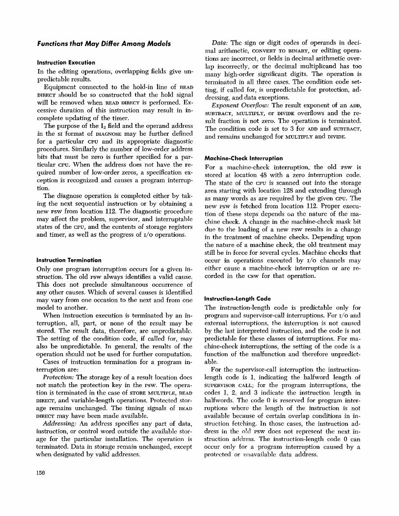
Functions that May Differ Among Models
Instruction Execution
In the editing operations, overlapping fields give unpredictable results.
Equipment connected to the hold-in line of READ
DIRECT should be so constructed that the hold signal will be removed when READ DIRECT is performed. Excessive duration of this instruction may result in incomplete updating of the timer.
The purpose of the 12 field and the operand address in the SI format of DIAGNOSE may be further defined for a particular CPU and its appropriate diagnostic procedures. Similarly the number of low-order address bits that must be zero is further specified for a particular CPU. When the address does not have the required number of low-order zeros, a specification exception is recognized and causes a program interruption.
The diagnose operation is completed either by taking the next sequential instruction or by obtaining a new psw from location 112. The diagnostic procedure may affect the problem, supervisor, and interruptable states of the CPU, and the contents of storage registers and timer, as well as the progress of I/O operations.
Instruction Termination
Only one program interruption occurs for a given instruction. The old psw always identifies a valid cause. This does not preclude simultaneous occurrence of any other causes. Which of several causes is identified may vary from one occasion to the next and from one model to another.
When instruction execution is terminated by an interruption, all, part, or none of the result may be stored. The result data, therefore, are unpredictable. The setting of the condition code, if called for, may also be unpredictable. In general, the results of the operation should not be used for further computation.
Cases of instruction termination for a program interruption are:
Protection: The storage key of a result location does not match the protection key in the psw. The operation is terminated in the case of STORE MULTIPLE, READ
DIRECT, and variable-length operations. Protected storage remains unchanged. The timing signals of READ
DIRECT may have been made available. Addressing: An address specifies any part of data,
instruction, or control word outside the available storage for the particular installation. The operation is terminated. Data in storage remain unchanged, except when designated by valid addresses.
156
Data: The sign or digit codes of operands in decimal arithmetic, CONVERT TO BINARY, or editing operations are incorrect, or fields in decimal arithmetic overlap incorrectly, or the decimal multiplicand has too many high-order significant digits. The operation is terminated in all three cases. The condition code setting, if called for, is unpredictable for protection, addressing, and data exceptions.
Exponent Overflow: The result exponent of an ADD,
SUBTRACT, MULTIPLY, or DIVIDE overflows and the result fraction is not zero. The operation is terminated. The condition code is set to 3 for ADD and SUBTRACT,
and remains unchanged for MULTIPLY and DIVIDE.
Machine-Check Interruption
For a machine-check interruption, the old psw is stored at location 48 with a zero interruption code. The state of the CPU is scanned out into the storage area starting with location 128 and extending through as many words as are required by the given CPU. The new psw is fetched from location 112. Proper execution of these steps depends Oil the nature of the machine check. A change in the machine-check mask bit due to the loading of a new psw results in a change in the treatment of machine checks. Depending upon the nature of a machine check, the old treatment may still be in force for several cycles. Machine checks that occur in operations executed by I/O channels may either cause a machine-check interruption or are recorded in the csw for that operation.
Instruction-Length Code
The instruction-length code is predictable only for program and supervisor-call interruptions. For I/O and external interruptions, the interruption is not caused by the last interpreted instruction, and the code is not predictable for these classes of interruptions. For machine-check interruptions, the setting of the code is a function of the malfunction and therefore unpredictable.
For the supervisor-call interruption the instructionlength code is 1, indicating the halfword length of SUPERVISOR CALL; for the program interruptions, the codes 1, 2, and 3 indicate the instruction length in halfwords. The code 0 is reserved for program interruptions where the length of the instruction is not available because of certain overlap conditions in instruction fetching. In those cases, the instruction address in the old psw does not represent the next instruction address. The instn~ction-Iength code 0 can occur only for a program interruption caused by a protected or unavailable data address.

Timer
Updating of the timer may be omitted when I/O data transmission approaches the limit of storage capability.
System Control Panel
The system-reset function may correct the parity of general and floating-point registers, as well as the parity of the psw.
The number of data switches is sufficient to allow storing of a full physical storage word. Correct parity generation is provided. In some models, either correct or incorrect parity is generated under switch control.
The data in the storage, general register or floatingpoint register location, or the instruction-address part of the psw as specified by the address switches and the storage-select switch can be displayed by the display key. When the location designated by the address switches and storage-select switch is not available, the displayed information is unpredictable. In some models, the instruction address is permanently displayed and hence is not explicitly selected.
When the· address-comparison switches are set to the stop position, the address in the address switches is compared against the value of the instruction address on some models, and against all addresses on others. Comparison includes only that part of the instruction address corresponding to the physical word size of storage.
Comparison of the entire halfword instruction address is provided in some models, as is the ability to compare data addresses.
The test light may be on when one or more diagnostic functions under control of DIAGNOSE are activated, or when certain abnormal circuit breaker or thermal conditions occur.
Normal Channel Operation
Channel capacity depends on the way I/O operations are programmed and the activity in the rest of the system. In view of this, an evaluation of the ability of a specific I/O configuration to function concurrently must be based on the application. Two systems employing identical complements of I/O devices may be able to execute certain programs in common, but it is possible that other programs requiring, for example, data chaining may not run on one of the systems.
The time when the interruption due to the PCI flag occurs depends on the model and the current activity. The channel may cause the interruption an unpredictable time after control of the operation is taken over by the csw containing the PCI flag.
The content of the count field in a csw associated
with an interruption due to the PCI flag is unpredictable. The content of the count field depends upon the model and its current activity.
When the channel has established which device on the channel will cause the next I/O interruption, the identity of the device is preserved in the channel. Except for conditions associated with termination of an operation at the subchannel, the current assignment of priority for interruptions among devices mayor may not be canceled when START r/o or TEST r/o is issued to the channel, depending upon the model.
The assignment of priority among requests for interruption from channels is based on the type of channel. The priorities of selector channels are in the order of their addresses, with channel 1 having the highest priority. The interruption priority of the multiplexor channel is not fixed, and depends on the model and the current activity in the channel.
Channel Programming Errors
A data address referring to a location not provided in the model normally causes program check when the device offers a byte of data to be placed at the nonexistent location or requests a byte from that location. Models in which the channel does not have the capacity to address 16,777,216 bytes of storage cause program check whenever the address is found to exceed the addressing capacity of the channel.
In the following cases, action depends on the addressing capacity of the model.
1. When the data address in the ccw deSignated by the CAW exceeds the addressing capacity of the model, the I/O operation is not initiated and the csw is stored during the execution of START rio. Normally an invalid data address does not preclude the initiation of the operation.
2. When the data address in a ccw fetched during command chaining exceeds the addressing capacity of the model, the I/O operation is not initiated.
3. When a ccw fetched on data chaining contains an address exceeding the addressing capacity of the model and the device signals channel end immediately upon transferring the last byte designated by the preceding ccw, program check is indicated to the program. Normally, program check is not indicated unless the device attempts to transfer one more byte of data.
4. Data addresses are not checked for validity during skipping, except that the initial data address in the ccw cannot exceed the addressing capacity of the model.
When the channel detects program check or protection check, the content of the count field in the associated csw is unpredictable.
Appendix G 157

When a programming error occurs in the inform a -tion placed in the CAW or ccw and the addressed channel or sub channel is working, either condition code 1 or 2 may be set, depending on the model. Similarly, either code 1 or 3 may be set when a programming error occurs and a part of the addressed I/O system is not operational.
When a programming error occurs and the addressed device contains an interruption condition, with the channel and sub channel in the available state, START I/O mayor may not clear the interruption condition, depending on the type of error and the model. If the instruction has caused the device to be interrogated, as indicated by the presence of the busy bit in the csw, the interruption condition has been cleared, and the csw contains program check, as well as the status from the device.
When the channel detects several error conditions, all conditions may be indicated or only one may appear in the csw, depending on the condition and the model.
Channe~ Equipment Errors
Parity errors detected by the channel on data sent to or received from the I/O device on some models cause the current operation to be terminated. When the channel and the CPU share common equipment, parity errors on data may cause malfunction reset to be performed. The recovery procedure in the channel and
158
subsequent state of the sub channel upon a malfunction reset depend on the model.
Detection of channel control check or interface control check causes the current operation, if any, to be immediately terminated and causes the channel to perform the malfunction-reset function. The recovery procedure in the channel and the subsequent state of the sub channel upon a malfunction reset depend on the model.
The contents of the csw, as well as the address in the psw identifying the I/O device, are unpredictable upon the detection of a channel-control-check condition.
Execution of malfunction reset in the channel depends on the type of error and model. It may cause all operations in the channel to be terminated and all operational subchannels to be reset to the available state. The channel may send the malfunction-reset signal to the device connected to the channel at the time the malfunctioning is detected, or a channel sharing common equipment with the CPU may send the system-reset signal to all devices attached to the channel.
The method of processing a request for interruption due to equipment malfunctioning, as indicated by the presence of the channel-data-check, channel-controlcheck, and interface-control-check conditions, depends on the model. In channels sharing common equipment with the CPU, malfunctioning detected by the channel may be indicated by the machine-check interruption.

Alphabetic List of Instructions NAME MNEMONIC TYPE EXCEPTIONS CODE
Compare Halfword CH RX C A,S 49 The listings in the TYPE and EXCEPTIONS columns mean: Compare Logical CLR RR C 15 A Addressing exception Compare Logical CL RX C A,S 55 C Condition code is set Compare Logical CLI SI C A 95 D Data exception Compare Logical CLC SS C A D5 DF Decimal-overflow exception Compare (Long) CDR RRF,C S 29 DK Decimal-divide exception Compare (Long) CD HXF,C A,S 69 E Exponen t -overflow exception Compare (Short) CER RRF,C S 39 EX Execute exception Compare (Short) CE RXF,C A,S 79 F Floating-point feature Convert to Binary CVB RX A,S,D, IK 4F FK Floating-point divide exception Convert to Decimal CVD RX P,A,S 4E IF Fixed-point overflow exception Diagnose SI M, A,S 83 IK Fixed-point divide exception Divide DR RR S, IK ID L New condition code loaded Divide D RX A,S, IK 5D LS Significance exception Divide Decimal DP SS T P,A,S,D, DK FD M Privileged-operation exception Divide (Long) NDDR RRF S,U,E,FK 2D N Normalized operation Divide (Long) NDD RXF A,S,U,E,FK 6D P Protection exception Divide (Short) NDER RRF S,U,E,FK 3D S Specification exception Divide (Short) NDE RXF A,S,U,E,FK 7D T Decimal feature
Edit ED SS T,C P,A, D, DE U Exponent-underflow exception Edit and Mark EDMK SS T,C P,A, D, DF Y Direct control feature Exclusive OR XR RR C 17 Z Protection feature Exclusive OR X RX C A,S 57
NAME MNEMONIC TYPE EXCEPTIONS CODE Exclusive OR XI SI C P,A 97
Add AR RR C IF lA Exclusive OR XC SS C P,A D7
Add A RX C A,S, IF 5A Execute EX RX A,S, EX 44
Add Decimal AP SS T,C P,A, D, DF FA Halt 110 HIO SI CM 9E Add Halfword AH RX C A,S, IF 4A Halve (Long) HDR RRF S 24 Add Logical ALR RR C IE Halve (Short) HER RRF S 34 Add Logical AL RX C A,S, 5E Insert Character IC RX A 43 Add Normalized Insert Storage Key ISK RRZ M, A,S 09
(Long) NADR RRF,C S,U,E,LS 2A Load LR RR 18 Add Normalized Load L RX A,S 58
(Long) NAD RXF,C A,S,U,E,LS 6A Load Address LA RX 41 Add Normalized Load and Test LTR RR C 12
( Short) NAER RRF,C S,U,E,LS 3A Load and Test Add Normalized (Long) LTDR RRF,C S 22
( Short) NAE RXF,C A,S,U,E,LS 7A Load and Test Add Unnorm- ( Short) LTER RRF,C S 32
alized (Long) AWR RRF,C S, E,LS 2E Load Complement LCR RR C IF 13 Add Unnorm- Load Complement
alized (Long) AW RXF,C A,S, E,LS 6E (Long) LCDR RRF,C S 23 Add Unnorm- Load Complement
alized (Short) AUR RRF,C S, E,LS 3E ( Short) LCER RRF,C S 33 Add Unnorm- Load Halfword LH RX A,S 48
alized (Short) AU RXF,C A,S, E,LS 7E Load (Long) LDR RRF S 28 AND NR RR C 14 Load (Long) LD RXF A,S 68 AND N RX C A,S 54 Load Multiple LM RS A,S 98 AND NI SI C P,A 94 Load Negative LNR RR C 11 AND NC SS C P,A D4 Load Negative Branch and Link BALR RR 05 ( Long) LNDR RRF,C S 21 Branch and Link BAL RX 45 Load Negative Branch on ( Short) LNER RRF,C S 31
Condition BCR RR 07 Load Positive LPR RR C IF 10 Branch on Load Positive
Condition BC RX 47 ( Long) LPDR RRF,C S 20 Branch on Count BCTR RR 06 Load Positive Branch on Count BCT RX 46 (Short) LPER RRF,C S 30 Branch on Index Load PSW LPSW SI LM, A,S 82
High BXH RS 86 Load (Short) LER RRF S 38 Branch on Index Load (Short) LE RXF A,S 78
Low or Equal BXLE RS 87 Move MVI SI P,A 92 Compare CR RR C 19 Move MVC SS P,A D2 Compare C RX C A,S 59 Move Numerics MVN SS P,A Dl Compare Decimal CP SS T,C A, D F9 Move with Offset MVO SS P,A Fl
Appendix G 159

NAME MNEMONIC TYPE EXCEPTIONS CODE List of Instructions by Set and Feature Move Zones MVZ SS P,A D3 Multiply MR RR . S lC
Standard Instruction Set Multiply M RX A,S 5C Multiply Decimal MP SS T P,A,S,D FC
EXCEPTIONS CODE 4C NAME MNEMONIC TYPE Multiply Halfword MH RX A,S
RR C IF lA Multiply (Long) NMDR RRF S,U,E 2C Add AR
Multiply (Long) NMD RXF A,S,U,E 6C Add A RX C A,S, IF 5A
Multiply (Short) NMER RRF S,U,E 3C Add Halfword AH RX C A,S, IF 4A
Multiply (Short) NME RXF A,S,U,E 7C Add Logical ALR RR C IE Add Logical AL RX C A,S, 5E
OR OR RR C 16 AND NR RR C 14
OR 0 RX C A,S 56 AND N RX C A,S 54
OR 01 SI C P,A 96 AND NI SI C P,A 94 OR DC SS C P,A D6 AND NC SS C P,A D4 Pack PACK SS P,A F2 Branch and Link BALR RR 05 Read Direct RDD SI Y M,P,A 85 Branch and Link BAL RX 45 Set Program Mask SPM RR L 04 Branch on Set Storage Key SSK RRZ M, A,S 08 Condition BCR RR 07 Set System Mask SSM SI M, A 80 Branch on Shift Left Double SLDA RS C S, IF 8F Condition BC RX 47 Shift Left Double Branch on Count BCTR RR 06
Logical SLDL RS S 8D Branch on Count BCT RX 46 Shift Left Single SLA RS C IF 8B Branch on Index Shift Left Single High BXH RS 86
Logical SLL RS 89 Branch on Index Shift Right Double SRDA RS C S 8E Low or Equal BXLE RS 87 Shift Right: Double Compare CR RR C 19
Logical SRDL RS S 8C Compare C RX C A,S 59 Shift Right: Single SRA RS C 8A Compare IIalfword CH RX C A,S 49 Shift Right Single Compare Logical CLR RR C 15
Logical SRL RS 88 Compare Logical CL RX C A,S 55 Start I/O SID SI CM 9C Compare Logical CLC SS C A D5 Store ST RX P,A,S 50 Compare Logical CLI SI C A 95 Store Character STC RX P,A 42 Convert to Binary CVB RX A,S,D, IK 4F Store Halfword STH RX P,A,S 40 Convert to Decimal CVD RX P,A,S 4E Store (Long) STD RXF P,A,S 60 Diagnose SI M, A,S 83 Store Multiple STM RS P,A,S 90 Divide DR RR S, IK ID Store (Short) STE RXF P,A,S 70 Divide D RX A,S, IK 5D Subtract SR RR C IF IB
Exclusive OR XR RR C 17 Subtract S RX C A,S, IF 5B Exclusive OR X RX C A,S 57 Subtract Decimal SP SS T,C P,A, D, DF FB Exclusive OR XI SI C P,A 97 Subtract Halfword SH RX C A,S, IF 4B Exclusive OR XC SS C P,A D7 Subtract Logical SLR RR C IF Execute EX RX A,S, EX 44 Subtract Logical SL RX C A,S 5F
Subtract N orm- Halt I/O HID SI CM 9E alized ( Long) NSDR RRF,C S,U,E,LS 2B Insert Character IC RX A 43
Subtract Norm- Load LR RR 18 alized ( Long) NSD RXF,C A,S,U,E,LS 6B Load L RX A,S 58
Subtract Norm- Load Address LA RX 41 alized (Short) NSER RRF,C S,U,E,LS 3B Load and Test LTR RR C 12
Subtract Norm- Load Complcmcnt LCR RR C IF 13 alized (Short) NSE RXF,C A,S,U,E,LS 7B Load Halfword LH RX A,S 48
Subtract Unnorm- Load Multiple LM RS A,S 98 alized (Long) SWR RRF,C S, E,LS 2F Load Negative LNR RR C 11
Subtract Unnorm- Load Positive LPR RR C IF 10 alized ( Long) SW RXF,C A,S, E,LS 6F LoadPSW LPSW SI LM, A,S 82
Subtract U nnorm- Move MVI SI P,A 92 alized (Short) SUR RRF,C S, E,LS 3F Move MVC SS P,A D2
Subtract Unnorm- Move Numerics MVN SS P,A Dl alized (Short) SU RXF,C A,S, E,LS 7F Move with Offset MVO SS P,A Fl
Supervisor Call SVC RR OA Movc Zones MVZ SS P,A D3 Test Channel TCH SI CM 9F Multiply MR RR S lC Test I/O TID SI CM 9D Multiply M RX A,S 5C Test Under Mask TM SI C A 91 Multiply I lalfword MH RX A,S 4C Translate TR SS P,A DC OR OR RR C 16 Translate and Test TRT SS C A DD OR 0 RX C A,S 56 Unpack UNPK SS P,A F3 OR 01 SI C P,A 96 Write Direct WRD SI Y M, A 84 OR OC SS C P,A D6 Zero and Add ZAP SS T,C P,A, D, DF F8 Pack PACK SS P,A F2
160
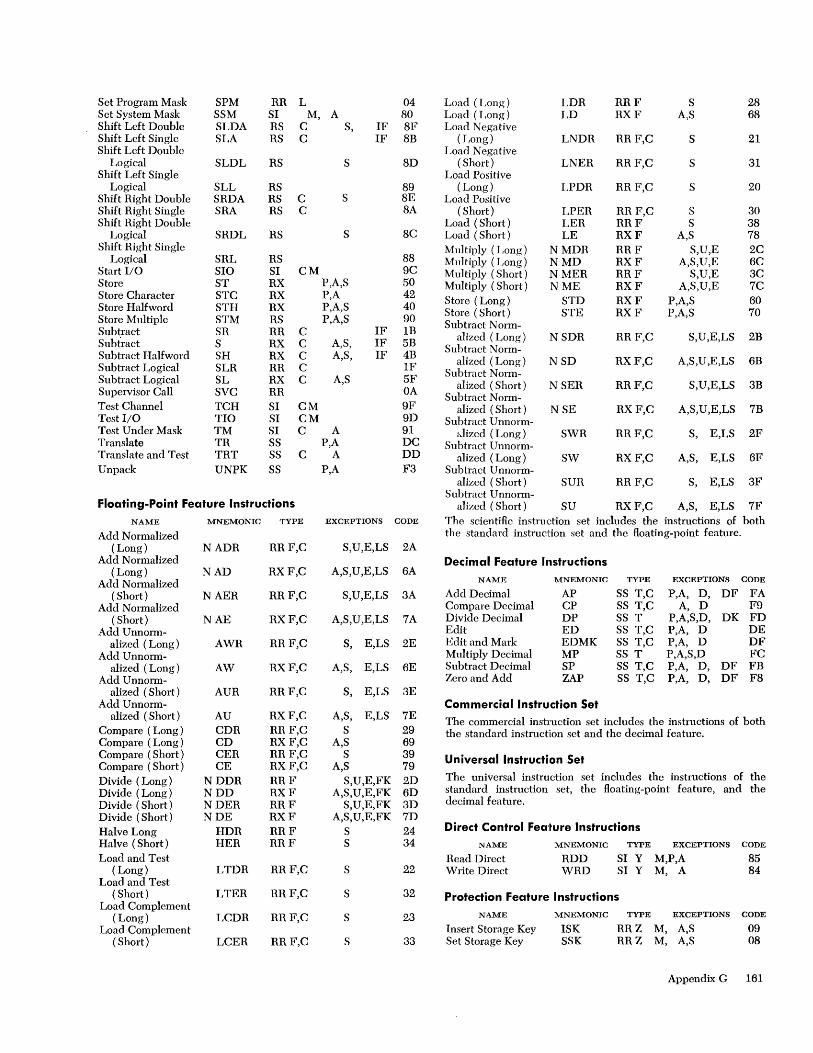
Set Program Mask SPM RR L 04 Load (Long) LDR RRF S 28 Set System Mask SSM SI M, A 80 Load (Long) LD RXF A,S 68 Shift Left Double SLDA RS C S, IF 8F Load Negative Shift Left Single SLA RS C IF 8B (Long) LNDR RRF,C S 21 Shift Left Double Load Negative
Logical SLDL RS S 8D ( Short) LNER RRF,C S 31 Shift Left Single Load Positive
Logical SLL RS 89 (Long) LPDR RRF,C S 20 Shift Right Double SRDA RS C S 8E Load Positive Shift Right Single SRA RS C 8A (Short) LPER RRF,C S 30 Shift Right Double Load (Short) LER RRF S 38
Logical SRDL RS S 8C Load (Short) LE RXF A,S 78 Shift Right Single Multiply (Long) NMDR RRF S,U,E 2C
Logical SRL RS 88 Multiply (Long) NMD RXF A,S,U,E 6C Start I/O SIO SI CM 9C Multiply (Short) NMER RRF S,U,E 3C Store ST RX P,A,S 50 Multiply (Short) NME RXF A,S,U,E 7C Store Character STC RX P,A 42 Store (Long) STD RXF P,A,S 60 Store Halfword STH RX P,A,S 40 Store (Short) STE RXF P,A,S 70 Store Multiple STM RS P,A,S 90 Subtract N orm-Subtract SR RR C IF 1B alized (Long) NSDR RRF,C S,U,E,LS 2B Subtract S RX C A,S, IF 5B Subtract Norm-Subtract Halfword SH RX C A,S, IF 4B alized (Long) NSD RXF,C A,S,U,E,LS 6B Subtract Logical SLR RR C IF
Subtract Norm-Subtract Logical SL RX C A,S 5F alized (Short) NSER RRF,C S,U,E,LS 3B Supervisor Call SVC RR OA Subtract Norm-Test Channel TCH SI CM 9F alized (Short) NSE RXF,C A,S,U,E,LS 7B Test I/O TIO SI CM 9D Subtract Unnorm-Test Under Mask TM SI C A 91 dizcd (Long) SWR RRF,C S, E,LS 2F Translate TR SS P,A DC Subtract Unnorm-Translate and Test TRT SS C A DD alized (Long) SW RXF,C A,S, E,LS 6F Unpack UNPK SS P,A F3 Subtract U nnorm-
alized (Short) SUR RRF,C S, E,LS 3F Subtract Unnorm-
Floating-Point Feature Instructions alized (Short) SU RXF,C A,S, E,LS 7F NAME MNEMONIC TYPE EXCEPTIONS CODE The scientific instruction set includes the instructions of both
Add Normalized the standard instruction set and the floating-point feature. ( Long) NADR RRF,C S,U,E,LS 2A
Add Normalized Decimal Feature Il1structions (Long) NAD RXF,C A,S,U,E,LS 6A
Add Normalized NAME MNEMONIC TYPE EXCEPTIONS CODE
( Short) NAER RRF,C S,U,E,LS 3A Add Decimal AP SS T,C P,A, D, DF FA Add Normalized Compare Decimal CP SS T,C A, D F9
( Short) NAE RXF,C A,S,U,E,LS 7A Divide Decimal DP SS T P,A,S,D, DK FD Add Unnorm- Edit ED SS T,C P,A, D DE
ali zed (Long) AWR RRF,C S, E,LS 2E Edit and Mark EDMK SS T,C P,A, D DF Add Unnorm- Multiply Decimal MP SS T P,A,S,D FC
alized (Long) AW RXF,C A,S, E,LS 6E Subtract Decimal SP SS T,C P,A, D, DF FB Add Unnorm- Zero and Add ZAP SS T,C P,A, D, DF F8
alized (Short) AUR RRF,C S, E,LS 3E Add Unnorm- Commercial Instruction Set
alized (Short) AU RXF,C A,S, E,LS 7E The commercial instruction set includes the instructions of both Compare (Long) CDR RRF,C S 29 the standard instruction set and the decimal feature. Compare (Long) CD RXF,C A,S 69 Compare (Short) CER RRF,C S 39 Universal Instruction Set Compare (Short) CE RXF,C A,S 79 Divide (Long) NDDR RRF S,U,E,FK 2D The universal instruction set includes the instructions of the
Divide (Long) NDD RXF A,S,U,E,FK 6D standard instruction set, the floating-point feature, and the
Divide (Short) NDER RRF S,U,E,FK 3D decimal feature.
Divide (Short) NDE RXF A,S,U,E,FK 7D Halve Long HDR RRF S 24 Direct Control Feajture Instructions Halve (Short) HER RRF S 34 NAME MNEMONIC TYPE EXCEPTIONS CODE
Load and Test Read Direct RDD SI Y M,P,A 85 (Long) LTDR RRF,C S 22 Write Direct WRD SI Y M, A 84
Load and Test ( Short) LTER RRF,C S 32 Protection Feature Instructions
Load Complement CODE (Long) LCDR RRF,C S 23 NAME MNEMONIC TYPE EXCEPTIONS
Load Complement Insert Storage Key ISK RRZ M, A,S 09 ( Short) LCER RRF,C S 33 Set Storage Key SSK RRZ M, A,S 08
Appendix G 161

Page
Instruction Formats by Mnemonic A RX 27
5A 7 8 11 12 15 16 19 20 31
AD RX (Long Operands) 44
6A 78 11 12 1516 1920 31
ADR RR (Long Operands) 44
I 2A Rl R2 Q 78 1112 15
AE RX (Short Operands) 44
7A
7 8 11 12 15 16 19 20 31
AER RR (Short Operands) 44
3A 78 11 12 15
AH RX 27
4A
7 8 11 12 15 16 1 9 20 31
AL RX 27
5E 7 8 11 12 15 16 19 20 31
ALR RR 27
1 E
78 1112 15
AP SS 35
7-_F_A __ ~_Ll~_L_2~~Bl~I~'?L~Dl~I_B~2~1~~ 7 8 11 12 15 16 1920 31 32 35 36 47
AR RR 27
lA
78 1112 15
AU RX (Short Operands) 45
7E 7 8 11 12 15 16 19 20 31
162
AUR RR
3E
AW RX
6E
AWR RR
2E
BAL RX
45
BALR RR
05
BC RX
(Short Operands)
7 8 11 12 15
(Long Operands)
7 8 11 12 1516 1920
(Long Operands)
78 111"l 15
7 8 11 12 15 16 19 20
78 1112 15
Page
45
45
31
45
64
31
64
63
~l ___ 4_7 __ ~~M~1~_X~2~~B2~~ ____ D~2~_~ 7 8 11 12 15 16 1920 31
BCR RR 63
07 78 1112 15
BCT RX 64
BCTR RR 64
06
78 11 12 15
BXH RS 64
7-__ 8_6 ____ ~_R~1~L-R~3~L-B~2~L------D~2~--~ 7 8 11 12 15 16 19 20 31
BXLE RS 65
87 7 8 11 12 15 16 19 20 31
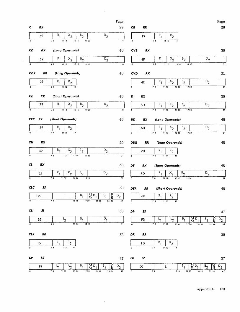
C RX
59
CD RX
69
CDR RR
29
CE RX
79
CER RR
C 39
CH RX
49
CL RX
7 8 11 12 1 5 16 1 9 20
(Long Operands)
7 8 1112 1516 1920
(Long Operands)
7 8 11 12 15
(Short Operands)
7 8 11 12 1516 1920
(Short Operands)
78 1112 15
7 8 11 12 15 16 1920
Page
29
31
46
31
46
46
31
46
29
31
53
c==i5 ____ ~_R_l~_X_2~ __ B2~1 _______ 0_2 ____ ~ 78 11 12 15 16 1920 31
CLC SS
7 8 1516
CLI SI 53
95 78 1516 1920 31
CLR RR 53
15 7 8 11 12 15
CP SS 37
~C= __ F_9 __ ~L,~I_L_2~B_,~IJ~?L_01~I_B_2~11[SJ o 78 1112 1516 1920 3132 3536 47
CR RR
19
CVB RX
4F
CVD RX
4E
D RX
50
DD RX
60
DDR RR
20
DE RX
70
DER RR
30
7 8 11 12 15
7 8 11 12 1516 1920
7 8 11 12 1516 1920
7 8 11 12 1516 1920
(Lon!r;J Operands)
7 8 11 12 15 16 19 20
(Long Operands)
78 1112 15
(Shol,t Operands)
7 8 11 12 1516 1920
(Shelrt Operands)
78 11 12 15
Page
29
30
31
31
31
30
31
48
31
48
48
31
48
37
~ __ FO __ ~L~1.~~_L~~_5lJ_,~?~_0~,I __ B2~11[SJ
DP SS
7 8 11 12 15 16 1920 31 32 35 36 47
DR RR 30
10 R1TR2J 7 8 11 12 15
ED SS 57
OE L. __ --'-_B, ---LI.J~?L_O 1.;...L.I_B_2 .....u11[SJ 7 8 1516 1920 31 32 35 36 47
Appendix G 163

EOMK 55
DF L 7 8 1516 1920
EX RX
44 7 8 11 1 2 1 5 16 19 20
HOR RR (Long Operands)
7 8 11 12 15
HER RR (Short Operands)
34 7 8 11 12 15
HIO SI
9E ~Bl 7 8 1516 1920
IC RX
43 7 8 11 1 2 15 16 19 20
ISK RR
09 78 1112 15
L RX
58 7 8 11 12 15 16 19 20
LA RX
41 7 8 11 12 15 16 19 20
LCOR RR (Long Operands)
7 8 11 12 15
LCER RIl (Short Operands)
33 7 8 11 12 15
164
3132 35 36
31
Page
58
47
65
31
47
47
94
55
31
73
25
31
56
31
43
43
Page
LCR RR 26
13
78 11 12 15
LO RX (Long Operands) 43
68 7 8 11 1 2 15 1 6 1 9 20 31
LOR RR (Long Operands) 43
7 8 11 12 15
LE (Short Operands) 43
I L ____ 7_8 ____ L-_R1~~X_2 __ ~B-2~~------D2----~ o 7 8 11 12 15 16 1920 31
LER RR (Short Operands) 43
38
7 8 11 12 15
LH RX 25
48 7 8 11 12 15 16 19 20 31
LM R5 26
7 8 11 1 2 15 16 1 9 20 31
LNOR RR (Long Operands) 44
21 78 11 12 15
LNER RR (Short Operands) 44
31 78 1112 15
LNR RR 26
7 8 11 12 15
LPOR RR (Long Operands) 43
20 7 8 11 12 15
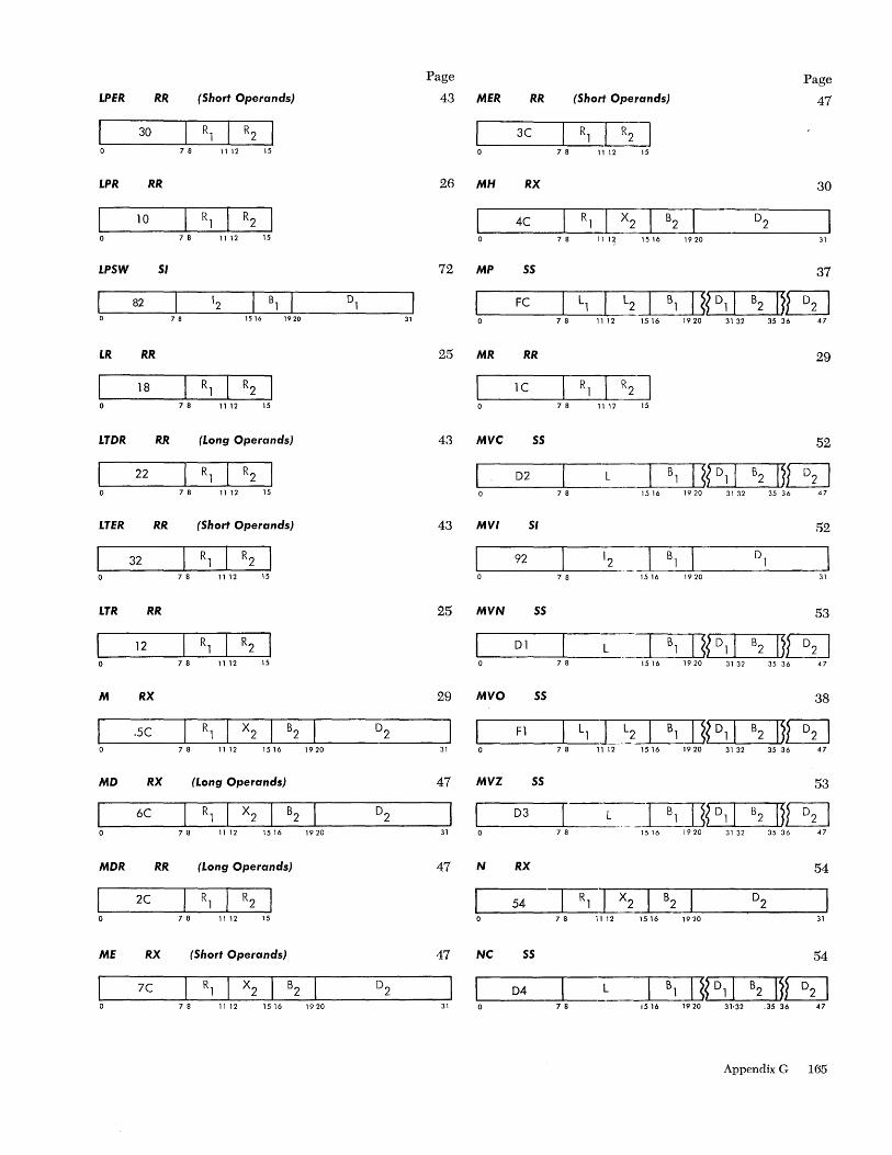
LPER RR (Short Operands)
30
78 11 12 15
LPR RR
10
7 8 11 12 15
LPSW SI
82 78 1516 1920
I.R RR
18 7 8 11 12 15
I.TDR RR (I.ong Operands)
22 7 8 11 12 15
I.TER RR (Short Operands)
78 1112 15
I.TR RR
c==='_1_2 ____ ~_R_1~ __ R_2~ 7 8 11 12 15
M RX
.5C 7 8 11 12 1516 1920
MD RX (I.ong Operands)
6C
7 8 11 12 1516 1920
MDR RR (I.ong Operands)
c===,_2_C ____ ~_R_l~ __ R_2~ 78 11 12 15
ME RX (Short Operands)
7C 7 8 11 1 2 15 16 1 9 20
31
Page
43
26
72
25
43
43
25
29
31
47
31
47
47
31
MER RR (Shorj' Operands)
Page
47
~I _3_C_..L...---R1_C}2 ] o 7 8 11 12 15
MH RX 30
~I ____ 4_C ____ ~_R_l_r==x2~ __ B_2~ ________ D_2 ______ ~ o 7 8 11 1 ~ 1 5 16 1 9 20 31
MP SS 37
~_F_C __ ~Ll_L5,~I_B_l~IJ~~_Dl~I_B_2~1}[5J 7 8 11 12 15 16 19 20 31 32 35 36 47
MR RR 29
1~ __ l_C __ -'-----R1_,[!2J o 78 1112 15
MVC SS 52
D2 7 8 35 36 47
MVI SI 52
92 '2 Bl ~------~----
7 8 1516 1920 31
MVN SS 53
~_D_1_....L---_,L __ =r2~?,--D_l I_B __ 2 -Ll1}[5J 78 1516 1920 3132 3536 47
MVO SS 38
~_F __ 1 __ ....L---L_1 LL2~_B_l ~1~J?~_Dl~I_B_2~1}[5J 7 8 11 12 15 16 19 20 31 32 35 36 47
MVZ SS 53
D3 L ....l.--B_l -'--JI ~?'-D~l I_B2 --LJI }[5J 7 8 1516 1920 3132 35 36 47
N RX 54
~1 ____ 5_4 ____ ~_R_l_~,~ __ B_2~ ________ D_2 ______ ~ o 7 8 ill 2 15 16 19 20 31
NC SS 54
D4 L _L----.-
B l---'IL.....I~?'---D ........ l I_B_2 --&.II }[5J 7 e 1516 1920 31'32 .35 36 47
Appendix G 165
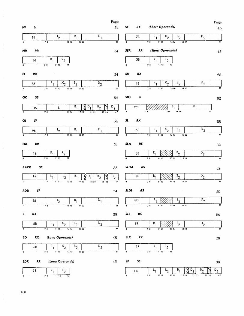
NI 51
Page
54
~ ____ L-___ 1_2 ____ L-_B1~L-______ D~1 ____ ~1 7 8 15 16 19 20 31
NR RR 54
14 78 11 12 15
o RX 54
~ ____ L-_R1~~X_2 __ ~B_2~~ ______ D2 ______ -Jl 7 8 11 12 15 16 19 20 31
OC .s;S 54
~_D_6 ___ ~ __ L __ ~B_1~1~~?L_D~d __ B2~1~~ 78 1516 1920 3132 3536 47
01 51 54
G o ---7~8------1~5-16--1-9~20-----------3~1
OR RR 54
16 78 11 12 15
PACK 55 38
~ __ F2 ___ ~_L~1 ~_L2~_B~1~1~~~D~1~I_B~2~IJ~ 7 8 11 12 15 16 1920 31 32 35 36 47
ROO 51 74
85 D1 7 8 1516 1920 31
5 RX 28
~ ____ L-_R~1-L __ X~2~ __ B~2~ _______ D_2 ______ ~ 7 8 11 12 1516 1920 31
SO RX (Long Operands) 45
31
SOR RR (Long Operands) 45
Q __ ~R_l ~I_R_; --J] 78 11 12 15
166
SE RX (Short Operands)
7B
7 8 11 12 15 16 19 20
SER RR (Short Operands)
3B
78 11 12 15
SH RX
48 7 8 11 12 15 16 19 20
SIO 51
1~_9_C __ ~~~~~~~Bl~ ____ ~Dl ____ .J o 7 B IS 16 1920 31
SL RX
5F 78 1112 1516 1920
SLA RS
8B 7 8 11 12 1516 1920
SLOA RS
Page
45
31
45
28
31
92
28
31
32
31
32
~ ___ 8F __ ~~R~1~~~~~'B_2~ ______ D_2 __ ~ 11'12 1516 7 8 1920 31
SLOL RS 59
8D I~ 7 8 1112 1516 1920 31
511 RS 59
89 7 8 11 12 1516 1920 31
SLR RR 28
78 1112 15
SP SS 36
~_F_B __ ~L~1~I __ L2~_B_l ~IJ~?~~Dl~I_B_2~IJ~ 78 1112 1516 1920 3132 3536 47
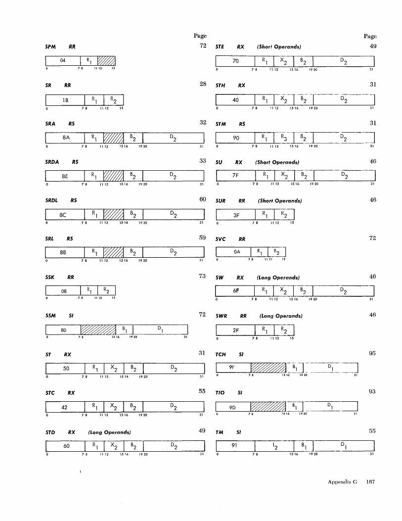
SPM 'RR
04
78 1112 15
SR RR
1 B 78 11 12 15
SRA RS
8A
78 11 12 1516 1920
SRDA RS
8E 7 8 1112 1516 1920
SRDL RS
8e I~ 78 11 12 1516 1920
SRL RS
88 I~ 7 8 1112 1516 1920
SSK RR
08 78 11 12 15
SSM SI
80 78 1516 1920 31
ST RX
50 7 8 11 12 15 16 19 20
STC RX
42 7 8 11 12 15 16 19 20
STD RX (Long Operands)
60 7 8 11 12 15 16 19 20
Page
72 STE RX (Shorf Operands)
Page
49
28
32
31
33
31
60
31
59
31
73
72
31
31
55
31
49
31
70 7 8 11 1 2 15 16 1 9 20
STH RX
40 7 8 11 12 1516 1920
STM RS
7 8 11 12
su RX (Short Operands)
7F
7 8 11 12 1516 1920
SUR RR (Short Operands)
3F R113J 78 11 12 15
SVC RR
1 OA R] 13] .... 0 --------7 ..... 8--1--'1-1:! 15
SW RX
6F
SWR RR
2F
TCH SI
9F
TIO SI
(Long Operands)
R1 0 B2 7 8 11 12 15 16 19 20
(Lon!1 Operands)
78 11 12 15
78 1516 1920
31
31
J 31
31
.0;--'--=] 31
46
31
46
72
46
J 31
46
95
31
93
~_9_D __ ~~~~~~iJ ___ D_]_~ 78 1516 1920 31
TM SI ss
91 12 '--=r=a!=r 78 1516 1920 31
Appendix G 167
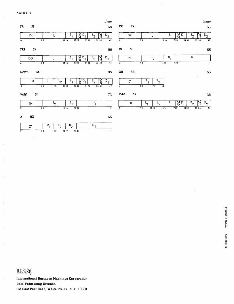
A22-6821-0
TR 55
OC 1 L B] 1 ~~ 0] 1 7 8 1516 1920 3132
TRT 55
00 L B] 1 ~~ 0] 1 78 1516 1920 3132
UNPK 5S
F3 L] L2 B] 1 ~~ D] 1 78 11 12 1516 1920 3132
WRD .51
I 84 ~ 12 B] 0 78 1516 1920
X RX
I 57 R] X2 B2 0 78 11 12 1516 1920
International Business Machines Corporation
Data Processing Division
112 East Post Road, White Plains, N. Y. 10601
B2
B2
B2
D]
D2
Page Page
56 XC 55 55
IU3J 07 1 L B] 1 ~~ 0] I B2 1~13] 35 36 47 7 8 1516 1920 3132 35 36 47
56 XI 51 55
1113] 97 12 B] 0] ~ 35 36 47 7 8 1516 1920 31
38 XR RR 55
1113] I ]7 R] R2 35 36 47 0 78 11 12 15
73 ZAP SS 36
F8 L] L2 B] 1 ~~ D] I B2 IJ13]
31 7 8 11 12 1516 1920 3132 35 36 47
55
31
Copyright © 2022 FDOKUMEN