HUBER 360® FIIT - LPG Systems
21
HUBER 360 ® FIIT TOUCHSCREEN USER GUIDE 1786 - © 2020. LPG SYSTEMS SA international/marketing - 955 route des Lucioles - 06560 Valbonne - France
-
Upload
khangminh22 -
Category
Documents
-
view
1 -
download
0
Transcript of HUBER 360® FIIT - LPG Systems

H U B E R 3 6 0 ® F I ITTOUCHSCREEN USER GUIDE
1786
- ©
202
0. L
PG S
YSTE
MS
SA in
tern
atio
nal/m
arke
ting
- 955
rout
e de
s Lu
ciol
es -
0656
0 Va
lbon
ne -
Fran
ce
2
1 PRESENTATION ................................................................................................... 3
2 INITIALIZATION .................................................................................................. 3
3 IDENTIFICATION ................................................................................................. 4
4 MENUS ................................................................................................................ 5
5 SETTINGS ........................................................................................................... 7
6 CUSTOMIZED EXERCISES .................................................................................1 5
7 ACTIVATION ..................................................................................................... 16
8 CONTROL PANEL .............................................................................................. 17
9 MANAGING ERRORS ........................................................................................ 20
Version 1 from 05/20
U S E R G U I D E Touch interface H U B E R 3 6 0 ® F I IT
© 2020. LPG and HUBER 360® are registered trademarks.Any reproduction, in part or in whole, is strictly prohibited.
> SUMMARY

3
> PRESENTATION
PR
ES
EN
TA
TIO
N
1 > INITIALIZATION
INIT
IAL
IZA
TIO
N
2This document describes the use of the software installed on HUBER 360®.
It is not intended to explain how to use the product, but merely to show how
the unit functions from the user’s point of view.
When the machine is turned on, a boot screen appears.
INITIALIZATION MACHINE
This screen allows you to initialize the HUBER 360® and to verify that is functioning properly.
It is important not to touch the handles and not to stand on the platform during this initialization phase as doing so will distort the values measured by the force sensors.
If the initialization is successful, you will hear a sound and the ID screen will appear.

4
> IDENTIFICATION
IDE
NT
IFIC
AT
ION
3 3
IDE
NT
IFIC
AT
ION
This screen allows the user to identify him or herself before starting their exercise.
To enter guest mode : Username : Man or Woman Password : 1234
> LOGGING OUT OF A SESSION
A session can be closed at any time in order to change the user ID. The icon for the user session is visible on the main screen:
A pop-up confirmation appears to confirm or cancel this action.
Press dispaly time or burger menu to close a session
> REGISTERED USER
A tablet must be connected to the machine to use this mode. In this case, the user’s data is read and the session data will be saved to the tablet.
The connection can be set up in two ways: • From the tablet (this connection mode will not described in this document)• From the machine touchscreen (via the virtual keyboard)
The user needs to fill out the following fields to identify him or herself:• User ID: Username• PASSWORD: User’s password
If the user ID or the password are incorrect, a pop-up error will be displayed.If they are correct, the program selection screen will be displayed.A new menu called « My programs » will appear on the main screen.
> AUTOMATIC LOG OUT
When the machine has not been used for 5 minutes, a log out request screen appears. This screen is the same as the one used to log out manually. The user can confirm or cancel the request to log out.
If the user does not react within 5 minutes, he or she will be automatically logged out of the session.
5
ME
NU
S
4 > MENUS 4
ME
NU
S
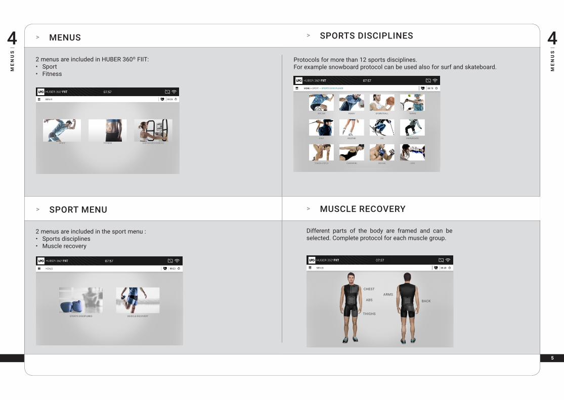
2 menus are included in HUBER 360® FIIT:• Sport• Fitness
2 menus are included in the sport menu :• Sports disciplines• Muscle recovery
SHOULDERS
HIPS
KNEES
ANKLES
THORACIC
LUMBAR
> SPORT MENU
Different parts of the body are framed and can be selected. Complete protocol for each muscle group.
CHEST
ABS
THIGHS
ARMS
BACK
> MUSCLE RECOVERY
Protocols for more than 12 sports disciplines.For example snowboard protocol can be used also for surf and skateboard.
> SPORTS DISCIPLINES

6
GLUTES
ME
NU
S
4 4
ME
NU
S
SHOULDERS
HIPS
KNEES
ANKLES
THORACIC
LUMBAR
3 menus are included in the fitness menu :• High Intensity Interval Training• Stretching• Assessment
Select from 1 to 4 goals and then click OK. Select a level and a duration
> FITNESS MENU
> HIGH INTENSITY INTERVAL TRAINING
CHEST
HAMSTRINGS
THORACIC
LUMBAR
GLUTES
CALVES
There are 5 tests in this menu : • Balance test • Strength test• Coordination test• Core stability test• Cardio test
Different parts of the body are framed and can be selected. Exercise for each muscle.
> STRETCHING
> FITNESS ASSESSMENT

7
> POSITION RECALL
As the protocol progresses, the position to be respected is recalled.
During a protocol it is represented by the 3D image of a person, and during the Free Menu by recalling the chosen positions of the feet and hands.
The arrows indicate the direction of the effort
> CONTROL BUTTONS
> DESCRIPTION OF STAGES
A description of the stage currently in progress is possible on the following table:
This table indicates, in the following order: • The number of repetitions completed
and remaining • the current series• remaining time before finishing the current stage.
This evolves as the protocol progresses.
> SETTINGS
RECALL
POSITION
SE
TT
ING
S
5 5
SE
TT
ING
S
DESCRIPTION
OF THE
CURRENT
STAGE
MAIN TARGET
SECONDARY
TARGET
CHANGE
TRAJECTORY
CHANGE
TARGET
CONTROL
BUTTONS
The exercise screen has different parts
Button Description
The protocol has started.
The protocol has been paused.
The protocol has been stopped.
These buttons allow the user to control the protocol:

8
> HANDLE TARGET
> PLATFORM TARGET
SE
TT
ING
S
5 5
SE
TT
ING
S
> TARGET TO REACH
There are two categories for target • Platform target: targeted positioning of the platform• Handle target: targeted force with the handles
The main target is displayed in the center of the screen by default. The scores displayed at the end of the exercises are solely based on this target.
The platform target shows the posture the user needs to assume to position his or her center of mass within the specified area.The target settings can be adjusted via the corresponding settings panel.
When two targets are displayed, each target needs to be reached one after the other.
A circular or elliptical motion can also be applied to the target.
Several scales are available in order to zoom in on the target: 1/8, 1/4, 1/2 and 1/1.
Once the target has been reached, it is highlighted.
The handle target is used for force exertion objectives. Several settings can be adjusted to increase or decrease the complexity as well as modify the exercise objectives: • Force objective • Target size
These settings can be adjusted via the corresponding control panel. If only one handle is being used, a single target is displayed.
Once the target has been reached, it is highlighted.
9
SE
TT
ING
S
5 > HANDLE TARGET SETTINGS 5
SE
TT
ING
S
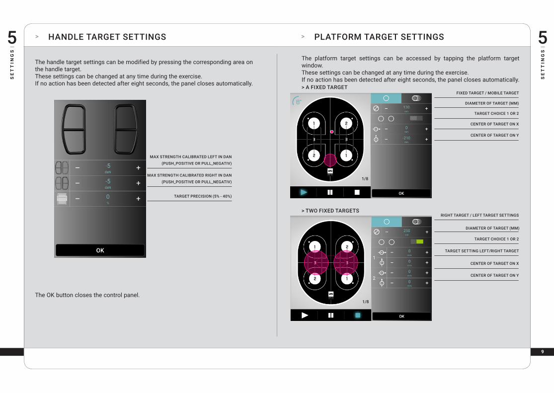
The handle target settings can be modified by pressing the corresponding area on the handle target.These settings can be changed at any time during the exercise.If no action has been detected after eight seconds, the panel closes automatically.
> PLATFORM TARGET SETTINGS
MAX STRENGTH CALIBRATED LEFT IN DAN
(PUSH_POSITIVE OR PULL_NEGATIV)
MAX STRENGTH CALIBRATED RIGHT IN DAN
(PUSH_POSITIVE OR PULL_NEGATIV)
TARGET PRECISION (5% - 40%)
FIXED TARGET / MOBILE TARGET
TARGET CHOICE 1 OR 2
CENTER OF TARGET ON X
RIGHT TARGET / LEFT TARGET SETTINGS
TARGET CHOICE 1 OR 2
TARGET SETTING LEFT/RIGHT TARGET
CENTER OF TARGET ON X
CENTER OF TARGET ON Y
DIAMETER OF TARGET (MM)
CENTER OF TARGET ON Y
DIAMETER OF TARGET (MM)
The platform target settings can be accessed by tapping the platform target window.These settings can be changed at any time during the exercise.If no action has been detected after eight seconds, the panel closes automatically.
The OK button closes the control panel.
> A FIXED TARGET
> TWO FIXED TARGETS

1 0
SE
TT
ING
S
5 > PLATFORM TARGET SETTINGS 5
SE
TT
ING
S
> ADJUSTING STAGE SETTINGS
ACTION TIME (S)
PAUSE TIME (S)
NUMBER OF REPETITIONS
REST TIME (S)
SERIAL NUMBER
TOTAL STAGE TIME
Stage settings can no longer be accessed once the exercise has been started.This panel is accessed by clicking on the description area of the current stage. If no action has been detected after eight seconds, the panel closes automatically.
> MOBILE TARGET ON AN ELLIPSE
The OK button closes the control panel.
FIXED TARGET / MOBILE TARGET
MOVEMENT ACCORDING TO ACTIVATED ELLIPSE
DIAMETER OF ELLIPSE MOVEMENT
CENTER OF THE MOVEMENT ELLIPSE IN X
CENTER OF THE MOVEMENT ELLIPSE IN Y
SPEED (1 TO 200 R/MINUTE)
MOBILE TARGET ACTIVATED
DIRECTION OF ROTATION
WIDTH / HEIGHT / ROTATION

1 1
> TRAJECTORY « POSITION » > TRAJECTORY « SPIRAL »
SE
TT
ING
S
5 5
SE
TT
ING
S
> ADJUSTING TRAJECTORY SETTINGS
Trajectory settings can no longer be accessed once the exercise has been started. This panel is accessed by clicking on the trajectory button. If no action has been detected after eight seconds, the panel closes automatically.
The trajectories are available in this panel.
Trajectory settings are adjusted using polar coordinates (with α and θ).
> TRAJECTORY « ELLIPSE »
INCLINATION OF POINT A (0°- 10°)
ROTATION OF POINT A (0°- 360°)
INCLINATION OF THE CENTER OF THE ELLIPSE (0° - 10°)
ROTATION OF THE CENTER OF THE ELLIPSE (0° - 360°)
LIMIT OF THE ELLIPSE ON X
LIMIT OF THE ELLIPSE ON Y
ORIENTATION OF THE ELLIPSE (0° - 360°)
PLATFORM SPEED (1% - 100%)
ACCELERATION (1 TO 3)
DIRECTION OF ROTATION
ANGLE OF SPIRAL CENTER (0°- 10°)
ROTATION OF SPIRAL CENTER (0°- 360°)
ENDING POINT OF SPIRAL (0°- 10°)
NUMBER OF CIRCLES (1 TO 15)
PLATFORM SPEED (1% - 100%)
ACCELERATION (1 TO 3)
DIRECTION OF ROTATION
OUTWARD - BACK

1 2
> TRAJECTORY « SUN » > TRAJECTORY « ROSETTE »
SE
TT
ING
S
5 5
SE
TT
ING
S
> DIAL TRAJECTORY > SEESAW TRAJECTORY
INCLINE OF POINT A (0° - 10°)
ROTATION OF POINT A (0° - 360°)
INCLINE OF POINT B (0° - 10°)
ROTATION OF POINT B (0° - 360°)
PLATFORM SPEED (1% - 100%)
ACCELERATION (1 TO 3)
INCLINE OF POINT A (0° - 10°)
ROTATION OF POINT A (0° - 360°)
LENGTH OF RAYS (5° - 20°)
ANGLE COVERED BY THE SUN (10° - 100°)
ANGLE BETWEEN THE RAYS (5° - 20°)
PLATFORM SPEED (1% - 100%)
ACCELERATION (1 TO 3)
DIRECTION OF ROTATION
ANGLE OF POINT A (0°- 10°)
ROTATION OF POINT A (0°- 360°)
ANGLE A (0° - 10°)
DIRECTION B (0° - 360°)
PLATFORM SPEED (1% - 100%)
ACCELERATION (1 TO 3)
ROTATION OF THE DIAL (0° - 360°)
LENGTH OF THE PETALS (2° - 10°)SHAPE OF THE PETALS: (PASSES THROUGH THE CENTER, BOUNCES BACK AT THE CENTER, DOES NOT PASS THROUGH THE CENTER)
ORIENTATION OF THE ELLIPSE (0° - 360°)
PLATFORM SPEED (1% - 100%)
ACCELERATION (1 TO 3)
DIRECTION OF ROTATION

1 3
SE
TT
ING
S
5 > RANDOM TRAJECTORY 5
SE
TT
ING
S
> FORCE CALIBRATION
Some protocols start out with a phase to calibrate the maximum force that can be exerted during the exercise.
There are as many calibration phases during an exercise as there are stages. These phases can be skipped using the close panel button, and the force can be manually adjusted during the exercise:
If this phase is not skipped, the user is asked to exert all of his or her strength while maintaining the recommended position. After exerting the force, the settings can be adjusted on each handle:
The maximum force percentage for the exercise is displayed at the top of the panel after it has been calibrated.
ANGLE OF COVERING CIRCLE (0° - 10°)
ROTATION OF CIRCLE CENTER (0° - 360°)
AMPLITUDE OF COVERED AREA (0° - 10°)
MAXIMUM SPEED (IN %)
MINIMUM SPEED (IN %)
ACCELERATION (1 TO 3)

1 4
SE
TT
ING
S
5 > SCORE > SCORE (SUITE) 5
SE
TT
ING
S
Heart rate data can be displayed if a heart rate monitor is worn during the exercise.
The buttons below the score can be used to perform the following actions if a program is in progress:
The i button: a score of 68 for stage 1 and 2 on the right was not high enough to validate the level. For this example, the first star.
Scores are displayed at the end of each exercise if at least one action has been started. Depending on the main target specified in the protocol, a platform or handle score is displayed.
A handle target score displays:• Average force (left + right)• Rate of coordination (left + right)• Achievement level
A platform target score displays:• Rate of coordination• Achievement level
The rate of coordination represents the total time on target over the total exercise time. It is displayed as a percentage.
The achievement level is displayed on the score screen as a number of stars. The next level is achieved if and only if:• The rate of coordination is greater than or equal to 70% in all stages. • The protocol has been completed in full
Button Description
Replay the protocol
Current program: perform the following protocolGuest mode: close the window
Detailed information on scores from each stage.

1 5
CU
ST
OM
IZE
D E
XE
RC
ISE
S
6 > SAVING A MODIFIED PROTOCOL > VISUALIZING CUSTOMIZED EXERCISES 6
CU
ST
OM
IZE
D E
XE
RC
ISE
S
The floppy disk icon can be used to save and name a modified protocol. Pressing this button will display customized exercises saved on the machine.
It is possible to save 20 customized exercises on your machine.

1 6
> HEART RATE MONITOR
The heart rate belt can still be configured from the Settings menu. Once a belt has been selected, cardiac rhythm appears in the «ToolBar».
The cardiac rhythm is used to calculate the average heart rate during the action stages. Once the belt has been disconnected and no other belt is present, cardiac rhythm will be erased.
> DELETING CUSTOMIZED EXERCISES
CU
ST
OM
IZE
D E
XE
RC
ISE
S
6
AC
TIV
AT
ION
7 > ACTIVATION
When the Bluetooth dongle is inserted, an icon appears:
When this icon is pressed, a pop-up window appears showing all heart rate monitors in the vicinity. A heart rate monitor can then be selected.
The selected heart rate monitor will be used throughout the entire session. It will be automatically deselected after logging out.
Press on the trash button and the exercises you want to delete to delete saved exercises.

1 7
> SETTING DATE AND TIME
> PRESENTATION
CO
NT
RO
L P
AN
EL
8 > SET LANGUAGE 8
CO
NT
RO
L P
AN
EL
The control panel is accessible from the main menu (carousel) as well as from the unit initialisation and user session screens. It is displayed as follows:
You can set the language on the screen as follows:
The choice of language is registered in a configure file once the language has changed. This same language will be used for the other applications (Application Setup).
Changing the language causes (in certain cases) the carousel to reset with new labels.
This screen allows you to adjust the date and time of the unit.
The date and time of the unit cannot be changed once the function has been activated. In addition, it is necessary to reboot the unit to register the changes.

1 8
> ADJUSTING SOUND LEVEL > SETTING BACKLIGHT
These two buttons allow the screen backlight to be increase or decrease.Changes are saved in the configuration file so that they are remembered after restarting the machine.
These two buttons adjust the sound level. There is also a mute button.Changes are saved in the configuration file so that they are remembered after restarting the machine.
CO
NT
RO
L P
AN
EL
8 8
CO
NT
RO
L P
AN
EL

1 9
> WIFI CONNECTION SETTINGS > UPDATES
This screen is used to select the wifi network to communicate with the tablet. Only wifi networks beginning with “lpg” are displayed.Changes are saved in the configuration file so that they are remembered after restarting the machine
The HUBER 360® software can be updated regularly. Updates require a USB stick containing a «xxxxpack-lpg» file. The following screen allows you to launch an update:
The cancel button allows you to leave this page and return to control panel.
The confirm button launches the «setup» application for updates. The screen turns off until the setup application has launched.
CO
NT
RO
L P
AN
EL
8 8
CO
NT
RO
L P
AN
EL
2 0
MA
NA
GIN
G E
RR
OR
S
9 > MAINTENANCE > MANAGING ERRORS
CO
NT
RO
L P
AN
EL
8
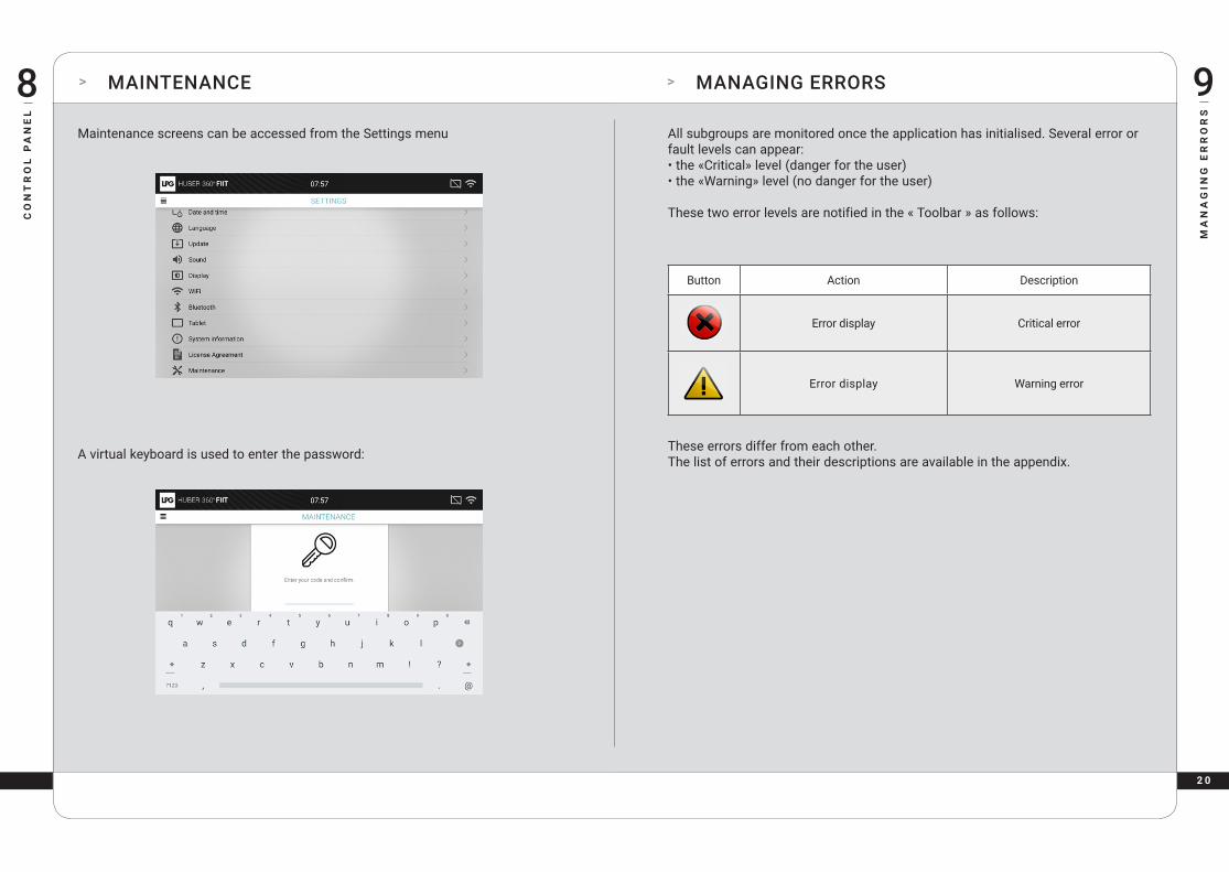
A virtual keyboard is used to enter the password:
Maintenance screens can be accessed from the Settings menu All subgroups are monitored once the application has initialised. Several error or fault levels can appear: • the «Critical» level (danger for the user) • the «Warning» level (no danger for the user)
These two error levels are notified in the « Toolbar » as follows:
Button Action Description
Error display Critical error
Error display Warning error
These errors differ from each other. The list of errors and their descriptions are available in the appendix.

2 1
> CRITICAL ERROR
Once a critical error has occurred, a pop-up appears on the screen:
9
MA
NA
GIN
G E
RR
OR
S
MA
NA
GIN
G E
RR
OR
S
9 > WARNING ERROR
SCREEN 49 :POP-UP FOR A CRITICAL ERROR
This pop-up lists all the detected errors (regardless of critical or warning level). All controls are now on «safety mode»: • the column has stopped • platform rotation has been halted
Confirming this message closes the pop-up, but the icon in the Toolbar remains even if the error disappears; all Critical errors will be maintained. At the same time, the controls cannot be restarted after a Critical error has occurred. Rebooting the unit allows you to reset the system and erase all errors.
Once a Warning error occurs, the Warning icon appears in the toolbar. In this case no pop-up appears and the controls are not set to «Safety mode».
The warning can only be seen by clicking on the Warning icon in the Toolbar.
SCREEN 50 : VISUALISATION OF WARNING ERRORS
When a Warning error message disapears, it is removed from the failings’ list.
If you have any questions about operating or maintaining your device, please contact your local dealer or LPG SYSTEMS customer service: LPG SYSTEMSTechnoparc de la Plaine - 30, rue du Dr Abel CS 90035 - 26902 Valence Cedex 09 - FranceTél. : +33 (0)4 75 78 69 00 / Fax : +33 (0)4 75 42 80 85