LPG Valves and Equipment
88
LPG Valves & Equipment 2022-2023 EDITION
-
Upload
khangminh22 -
Category
Documents
-
view
2 -
download
0
Transcript of LPG Valves and Equipment

LPG Valves & Equipment
2022-2023 EDITION

Solutions
LPGSOLUTIONS
COMPRESSED GASES SOLUTIONS
NATURAL GASSOLUTIONS
ALTERNATIVE FUELSYSTEMS
GAS METERING SOLUTIONS
INDUSTRIAL PROCESS MANAGEMENT
IoT
IoT
IoT
IoT

Solutions
LPGSOLUTIONS
COMPRESSED GASES SOLUTIONS
NATURAL GASSOLUTIONS
ALTERNATIVE FUELSYSTEMS
GAS METERING SOLUTIONS
INDUSTRIAL PROCESS MANAGEMENT
IoT
IoT
IoT
IoT
The Cavagna Group began operation in 1949 in Northern Italy and continues to grow today. Since its origin, the Group has become a world leader in the forging and machining of brass and stainless steel.
For over seventy years the Group has supplied safe products of superior quality and value. Technological advancement and sophisticated working procedures have allowed us to rapidly create new products and solutions for the gas control industry.
The Cavagna Group produces a wide range of products meeting international standards including:
• LPG Valves, Equipment and Regulators• Engineering and Services dedicated to the LPG industry• ASME, Fork Lift and Motor Fuel Tank Valves• Natural Gas regulators for domestic, commercial and industrial use• Gas meters• Compressed Gases Cylinder Valves• Specialty Gases Cylinder Valves• Refrigerant Gases Cylinder Valves• Regulation Equipment for Industrial Gases• Regulation Equipment for Medical Gases• Comprehensive Range of Welding, Cutting Equipment• CNG - H2 - AUTOGAS cylinder valves and filling valves• CNG - AUTOGAS systems
The Group’s design engineers and laboratory technicians closely cooperate with worldwide regulatory institutions, both in the writing of international performance standards and in the creation of new products.
The Cavagna Group of companies has invested heavily in personnel, individual training, and robotic technology to meet the quality standards required by our customers and the 150 countries we serve.
Our philosophy is to provide all of our customers with quality products, continuous innovation and superior service in a competitive environment.

www.cavagnagroup.com4
Cylinder Equipment pg.5Gas Phase Valves pg.6Liquid Phase Valves pg.10Level Indicator pg.12Camping Valves pg.14Dual Phase Valves pg.15
Cylinder Filling Heads pg.17Filling Heads pg.18
Tank Equipment pg.35Pressure Relief Valves pg.36Safety Valves pg.38Filler Valve pg.40Liquid Withdrawal Valves pg.44Multi-Service Valves pg.46Float Gauges pg.50Safety Valves pg.52
Transport Tanker / Bobtail Equipment pg.53Internal Valves pg.54Actuators pg.62Remote Release pg.63Float Gauges pg.64Rotary Gauge System pg.65Excess Flow Valves pg.65Back Pressure Valves pg.70Filling Head pg.70Hose End Connectors pg.71Multipurpose Valves pg.72Double Check Filler Valves pg.72Internal Relief Valves pg.74Globe and Angle Valves pg.75Accessories pg.76Pressure Relief Valves pg.78Wafer pg.79

www.cavagnagroup.com 5
CYLINDEREQUIPMENT

6
CYL
IND
ER
EQUI
PMEN
TC
YLIN
DER
FI
LLIN
G H
EAD
STA
NK
EQUI
PMEN
TTR
AN
SPO
RT T
AN
KER
/ BO
BTA
IL E
QUI
PMEN
T
www.cavagnagroup.com
The products shown represent only some configurations and solutions of the wider range available.
Handwheel ValvesGAS PHASE VALVES
Part number Container connection* Outlet connection*
8002901109 17E W 21.8 x 1/14” LH
8004903082 25E G1/2 LH
8062901059 25.5 x 2 CIGPL / NF88-765 W 20 x 1/14” LH
8002901209 KG 19.3 x 1/14” Taper 6 to cone STAS 2667-89 W 21.8 x 1/14” LH
8003902051 23.2 x 2 GPL Cone 10% 21.7 x 1.814
8002901146 17E W 21.8 x 1/14” LH
8064903098 17E W 21.8 x 1/14” LH
8002901145 25E .885”-14 NGO-LH-INT CGA 510
8002901227 3/4” - 14 NPT .885-14 NGO-LH CGA 510
8004903135 3/4” - 14 NPT .885-14 NGO-LH CGA 510
8064903218 M26x1.5-6e W21.8x1/14" - LH
8002901109
Open-close handwheel valve.Customizable upon request.
8062901209
Open-close handwheel valve.
Customizable upon request.
8004903135
Open-close handwheel valve.This valve also incorporates a fixed liquid level gauge.
8064903218
Open-close handwheel valve with diffuser for composite
cylinder.
8064903098
Open-close handwheel valve with
sediment tube.Customizable upon
request.
8003902051
Open-close handwheel valve with excess flow
limiter.
8004903082
Open-close handwheel valve. Customizable
upon request.
8002901227
PRONTO TAPOpen-close valve with POL outlet. With test Port
*inlet and outlet connection according to country standards

CYL
IND
ER
EQUI
PMEN
TC
YLIN
DER
FI
LLIN
G H
EAD
STA
NK
EQUI
PMEN
TTR
AN
SPO
RT T
AN
KER
/ BO
BTA
IL E
QUI
PMEN
T
7www.cavagnagroup.com
The products shown represent only some configurations and solutions of the wider range available.
Handwheel Valves with PRDGAS PHASE VALVES
Part number Container connection* Outlet connection* Relief Valve set pressure
8067906019 17E W 21.8 x 1/14” LH DIN 477 N°2 35 bar
8067906018 25E W 21,8 x 1/14”LH DIN 477 N°1 35 bar
8067906060 M26 x 1.5-6e W 21.8 x 1/14” LH DIN 477 N°2 35 bar
8006905027 25T G 5/8 LH N° 105 26 bar
8298908017 3/4" - 14 NGT 1.312” -5 ACME 2G RH-EXT 375 PSI (26 bar)
8006905016 3/4” - 14 NGT .885”-14 NGO-LH-INTCGA 510 375 PSI (26 bar)
8005904003 M26,2x2 1 1/4" 5 ACME-2G 26 bar
*inlet and outlet connection according to country standards
8067906019
Open-close handwheel valve with pressure relief device.
8006905016
DOT cylinder valve with a fixed liquid level gauge
8067906060
Open-close valve with pressure relief valve and plastic diffuser
for composite lpg cylinders.
Parallel threads inlet connection. (option of
different outlets)
8006905027
Open-close handwheel valve with pressure relief device.
8005904003
Open-close handwheel valve with pressure
relief device and ACME outlet.
8298908017
Cylinder valve OPD with secondary overfill protection device.

8
CYL
IND
ER
EQUI
PMEN
TC
YLIN
DER
FI
LLIN
G H
EAD
STA
NK
EQUI
PMEN
TTR
AN
SPO
RT T
AN
KER
/ BO
BTA
IL E
QUI
PMEN
T
www.cavagnagroup.com
The products shown represent only some configurations and solutions of the wider range available.
Click On ValvesGAS PHASE VALVES
6682900011
LPG Click On valve. Customizable upon request.
6682900022
LPG Click On valve with internal sphere excess flow device.
Customizable upon request.
6682900323
LPG Click On valve with pressure relief device and excess flow. Customizable upon request.
6682900263
LPG Click On valve with internal sphere excess flow device. Customizable upon request.
6682900249
LPG Click On valve with internal sphere excess flow device.Customizable upon
request.
6682900220
LPG Click On valve with Pressure Relief
Device and fusible plug. Customizable upon
request.
Bottom
Part number Container connection* Outlet connection* Relief Valve set pressure
6682900011 3/4” - 14 NGT ø 20 /
6682900022 ø 23.2 x 2 GPL Con. 10% ø 20 /
6682900323 3/4” - 14 NGT ø 20 26 bar
6682900263 M26 x 1.5-6e ø 20 26 bar
6682900249 ø 23.2 x 2 GPL Taper 10% ø 20 26 bar
6682900220 25E ø 22 21 bar
6602900313 ø 19.3 x 1.814 SI Taper 6° ø 27 26 bar
6682900070 ø 25.5x2 CIGPL ø 22 /
*inlet and outlet connection according to country standards

CYL
IND
ER
EQUI
PMEN
TC
YLIN
DER
FI
LLIN
G H
EAD
STA
NK
EQUI
PMEN
TTR
AN
SPO
RT T
AN
KER
/ BO
BTA
IL E
QUI
PMEN
T
9www.cavagnagroup.com
The products shown represent only some configurations and solutions of the wider range available.
Flat Top ValvesGAS PHASE VALVES
6682900253
LPG Flat top valve with pressure relief device.
Customizable upon request.
Weather sealed.
6682900052
LPG Click On valve. Customizable upon request.Weather sealed.
6682900328
LPG Flat top valve with pressure relief device.
Customizable upon request.
Weather sealed.
6682900327
LPG Flat top valve with pressure relief device
and dust retainer. Customizable upon
request.Weather sealed.
6682900320
LPG Flat top valve with pressure relief device. Customizable upon request.Weather sealed.
6682900224
LPG Flat top valve with dust retainer. Customizable upon request.Weather sealed.
Top Top
Top Top
Top Top
Part number Container connection* Outlet connection* Relief Valve set pressure
6682900253 ø 26.3 ± 0.075 x 2 Cone 10% CIGPL 88/765 ø 16 26 bar
6682900052 25E ø 19 /
6682900320 25E ø 21 /
6682900328 M26x1.5-6e ø 22 25 bar
6682900224 3/4” - 14 NGT ø 22 /
6682900327 ø 26.2±0.1x2 Con. 10% ø 22 25 bar
*inlet and outlet connection according to country standards
10
CYL
IND
ER
EQUI
PMEN
TC
YLIN
DER
FI
LLIN
G H
EAD
STA
NK
EQUI
PMEN
TTR
AN
SPO
RT T
AN
KER
/ BO
BTA
IL E
QUI
PMEN
T
www.cavagnagroup.com
The products shown represent only some configurations and solutions of the wider range available.
Jumbo Valves
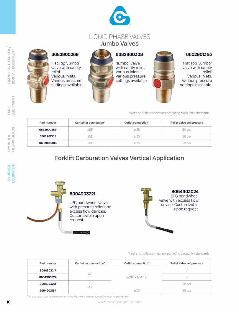
Forklift Carburation Valves Vertical Application
LIQUID PHASE VALVES
8064903024LPG handwheel
valve with excess flow device. Customizable
upon request.
8004903221
LPG handwheel valve with pressure relief and excess flow devices. Customizable upon request.
6682900269
Flat Top “Jumbo” valve with safety relief.Various inlets.Various pressure settings available.
6682900308
“Jumbo” valvewith safety relief.Various inlets.Various pressure settings available.
6602901355
Flat Top “Jumbo” valve with safety
relief.Various inlets.
Various pressure settings available.
Part number Container connection* Outlet connection* Relief Valve set pressure
806490321717E
W21.8 x 1/14” LH
/
8064903024 /
800490322125E
26 bar
8004903184 ø 22 35 bar
Part number Container connection* Outlet connection* Relief Valve set pressure
6682900269 25E ø 35 30 bar
6602901355 25E ø 35 26 bar
6682900308 25E ø 35 26 bar
*inlet and outlet connection according to country standards
*inlet and outlet connection according to country standards

CYL
IND
ER
EQUI
PMEN
TC
YLIN
DER
FI
LLIN
G H
EAD
STA
NK
EQUI
PMEN
TTR
AN
SPO
RT T
AN
KER
/ BO
BTA
IL E
QUI
PMEN
T
11www.cavagnagroup.com
The products shown represent only some configurations and solutions of the wider range available.
Forklift Carburation Valves Horizontal ApplicationLIQUID PHASE VALVES
Part number Container connection* Outlet connection* Relief Valve set pressure
8008908105
25E1-1/4” 5 ACME
26 bar8008908246
6602901275
ø 228008908175 17E
/8004903192 25E
8004903110 ø 22.1 ± 0.075 x 2 Cone 10% G.65
8004903208 17E ø 22
*inlet and outlet connection according to country standards
8064903217
LPG handwheel valve with filter. Customizable
upon request.
8008908246
LPG Forklift Carburation Quick Outlet Connection Valve with pressure relief and sintered filter.
8008908175
LPG Forklift Carburation Quick Connection Valve with excess flow devices.
8004903110
LPG Forklift Carburation Quick Connection Valve
with filter.
8004903192
LPG Forklift Carburation handwheel Valve with excess flow device and quick connection.Available different outlet tube
6602901275
LPG Forklift Carburation Quick Connection Valve
with pressure relief device, sinterized filter and mechanical level
indicator.Fusible plug version
available.

12
CYL
IND
ER
EQUI
PMEN
TC
YLIN
DER
FI
LLIN
G H
EAD
STA
NK
EQUI
PMEN
TTR
AN
SPO
RT T
AN
KER
/ BO
BTA
IL E
QUI
PMEN
T
www.cavagnagroup.com
The products shown represent only some configurations and solutions of the wider range available.
Valves with Pressure Level IndicatorLEVEL INDICATOR
8003902164
The level gauge shows the amount of gas reserve in the cylinder, with parameters based on customer’s request and the cylinder configuration.With excess flow limiter.
8003902180
The level gauge shows the amount of gas reserve
in the cylinder, with parameters based on
customer’s request and the cylinder configuration.
With excess flow limiter.
8062901223
The level gauge shows the amount of gas reserve
in the cylinder, with parameters based on
customer’s request and the cylinder configuration
8003902181
The level gauge shows the amount of gas reserve in the cylinder, with parameters based on customer’s request and the cylinder configuration.With excess flow limiter.
8008908197
The level gauge shows the amount of gas reserve in the cylinder (temperature sensitive level indicator).
Part number Container connection* Outlet connection*
8003902164 ø 23.2 x 2 GPL Taper 10% ø 21.7 x 1.814NFE 29-650 GPL LH
8003902180 ø 23.2 x 2 GPL Taper 10% ø 21.7 x 1.814NFE 29-650 GPL LH
8003902181 ø 23.2 x 2 GPL Taper 10% ø 21.7 x 1.814NFE 29-650 GPL LH
8062901223 ø 23.2 x 2 GPL Cone 10% W20 x 1/14” LH
8008908197 3/4” - 14 NGT 1.312-5 ACME - 2G RH-EXT
*inlet and outlet connection according to country standards

CYL
IND
ER
EQUI
PMEN
TC
YLIN
DER
FI
LLIN
G H
EAD
STA
NK
EQUI
PMEN
TTR
AN
SPO
RT T
AN
KER
/ BO
BTA
IL E
QUI
PMEN
T
13www.cavagnagroup.com
The products shown represent only some configurations and solutions of the wider range available.
Valves with Mechanical Level IndicatorLEVEL INDICATOR
8008908220
LPG Handwheel Valve with mechanical level indicator.
3009500048
Assembled dial
3089500005
Assembled dial for Jumbo valves
6602901275
LPG Forklift Carburation Quick Connection Valve with pressure relief device, sinterized filter and mechanical level indicator.Fusible plug version available.
6602900316
LPG 27 mm Quick Connection Valve with mechanical level indi-
cator.
6682900235
LPG Quick Connection Valve with mechanical audible level indicator.
6682900246
LPG Quick Connection Valve with mechanical audible level indicator.
Part number Container connection* Outlet connection* Relief Valve set pressure
6602900316 25E ø 27 26 bar
6682900235 ø 22.1 ± 0.075 x 2 Cone 10% ø 20 26 bar
8008908220 17E W21.8 x 1.14” LH 25 bar
6602901275 25E ø 22 26 bar
8008908203 25E .885-14 NGO LH INT
8008908204 25E .885-14 NGO LH INT
8008908206 25E .885-14 NGO LH INT
8008908210 17E .885-14 NGO LH INT
8008908211 25E .885-14 NGO LH INT
8008908220 17E W21.8 x 1/14” LH 25 bar
8008908223 17E W21.8x1/14" LH 25 bar
6682900246 25E G.56 26 bar
6682900254 25E G.56 26 bar
6682900255 25E G.56 26 bar
*inlet and outlet connection according to country standards

14
CYL
IND
ER
EQUI
PMEN
TC
YLIN
DER
FI
LLIN
G H
EAD
STA
NK
EQUI
PMEN
TTR
AN
SPO
RT T
AN
KER
/ BO
BTA
IL E
QUI
PMEN
T
www.cavagnagroup.com
The products shown represent only some configurations and solutions of the wider range available.
64B5900001
Self-closing Camping
64B5900002
Self-closing Camping
64B6900013
Camping valve with pressure relief device.
64B1900002
Camping valve.
64B2900007
Camping valve.
64B6900002
Camping valve with pressure relief device and dust retainer.
64B6900011
Camping valve with pressure relief device.
CAMPING VALVES
Part number Container connection* Outlet connection* Relief Valve set pressure
64B1900002 1/2" - 14 NGT W20x1.814 - LH
64B2900007 17E W20x1/14" LH 375 PSI
64B6900002 1/2" - 14 NGT 3/8" BSPF 2580 Kpa
64B6900011 3/4" - 14 NGT 3/8" - 19 BSPF - LH - EXT 175 PSI
64B6900012 18T 3/8" - 19 BSPF - LH - EXT 375 PSI
64B6900013 18T 3/8" - 19 BSPF - LH - EXT 375 PSI
64B5900001 M22 x 1.25 - 6g M16 x 1.5 - 6H /
64B5900002 M22 x 1.25 - 6g M16 x 1.5 - 6H /
*inlet and outlet connection according to country standards

CYL
IND
ER
EQUI
PMEN
TC
YLIN
DER
FI
LLIN
G H
EAD
STA
NK
EQUI
PMEN
TTR
AN
SPO
RT T
AN
KER
/ BO
BTA
IL E
QUI
PMEN
T
15www.cavagnagroup.com
The products shown represent only some configurations and solutions of the wider range available.
for Liquid & Gas PhasesDUAL PHASE VALVES
*inlet and outlet connection according to country standards
6704901028
LPG Dual Valve with pressure relief device and excess flow device. M 14 x 1 - 6H dip tube connection.
6704901036
LPG Dual Valve with pressure relief device
and excess flow device.Fast connection for
easy dip tube assembly.
Part number Container connection* Liquid Outlet connection*
Vapour Outlet connection*
Relief Valve set pressure
6704901036 3/4”-14 NGT .903 -14 NGO LH EXT CGA 555
.885-14 NGO LH INTCGA 510 26 bar
6704901028 25.5 x 2 CIGPL / NF88 - 765 1 1/4” - 5 ACME - 2G W21.8x1/14” LH 26 bar
6704901037 3/4”-14 NGT 0.625" - 18 UNF G5/8" LH 26 bar
6602901023
Connector for the outlet of Dual Valve.


CYLINDERFILLING HEADS

18
CYL
IND
ER
EQUI
PMEN
TC
YLIN
DER
FI
LLIN
G H
EAD
STA
NK
EQUI
PMEN
T
www.cavagnagroup.com
The products shown represent only some configurations and solutions of the wider range available.
TRA
NSP
ORT
TA
NKE
R /
BOBT
AIL
EQ
UIPM
ENT
for LPG Valves 16, 19 and 35mm(Jumbo and Kosanova valves)
Manually Operated
FILLING HEADS
Features
1. Balanced jig for easy suspension between filling operations.2. Easy to connect and disconnect. Filling is initiated by operating the manual handle.3. Slim design makes it easy to handle and it fits easily inside any shroud.
Inlet connection: G3/8 or W21,8 x 1/14 LH
Outlet connection: According to country standards.
Supply pressures: Designed to operate within the normal supply pressures.Liquid filling product: 1 - 15 barFilling time approx. 5 sec./kg LPG at 7 bar differential pressure.
Function and Maintenance: The Filling Head is easy to operate.The head outlet is attached to the valve inlet manually. While pressing the manual handle the filling heads makes a leak tight connection to the valve then opens the valve spindle and the gas starts to flow.When the cylinder is full the filling is stopped via the scale system. By moving the handle in its opposite direction the filling head disconnects from the valve.
MATERIALS AND STANDARDS
The Filling Head is made of corrosion resistant materials such as stainless steel, brass, aluminium and special polymers. The rubber materials used are developed and manufactured according to the requirements of EN 549.
Part number Inlet Connection* Outlet Connection*
6882900001 G3/8
ø 35 mm6882900002G3/8 or W 21,8 x 1/14 LH
6882900003
6882900004
G3/8
ø 16 mm
6882900005ø 19 mm
6882900006
6882900007ø 16 mm
6882900008 G3/8 or W 21,8 x 1/14 LH
Reference Image
*inlet and outlet connection according to country standards

19www.cavagnagroup.com
The products shown represent only some configurations and solutions of the wider range available.
CYL
IND
ER
EQUI
PMEN
TC
YLIN
DER
FI
LLIN
G H
EAD
STA
NK
EQUI
PMEN
TTR
AN
SPO
RT T
AN
KER
/ BO
BTA
IL E
QUI
PMEN
T
for LPG Valves 16, 19 and 35mm(Jumbo and Kosanova valves)
Semi-automatic
FILLING HEADS
Features
1. Balanced jig for easy suspension between filling operations.2. Easy to connect and disconnect. Filling is initiated by operating of the pneumatic air supply.3. Slim design makes it easy to handle and it fits easily inside any shroud.
Inlet connection: for LPG G3/8for Pneumatic air G1/4 according to country standards
Outlet connection: According to country standards.
Supply pressures: Designed to operate within the normal supply pressures. Pneumatic supply: 4 - 6 bar. Liquid filling product: 1 - 15 bar Filling time approx. 5 sec./kg LPG at 7 bar differential pressure.
Function and Maintenance: The Filling Head is easy to operate.The head outlet is attached to the valve inlet manually. Once the pneumatic pressure is applied to the head it forces the internal components of the head to move towards the valve top thereby establishing a leak tight connection and once this is established the further movement of the components forces the valve spindle to open and simultaneously the gas starts to flow. When the cylinder is full the filling is stopped by removing the pneumatic pressure. The internal springs of the head allows the valve to close and moves the components of the head backwards to stop the flow of gas and to disconnect the head from the valve. The head is removed manually.
MATERIALS AND STANDARDS
The Filling Head is made of corrosion resistant materials such as stainless steel, brass, aluminium and special polymers. The rubber materials used are developed and manufactured according to the requirements of EN 549.
Part number Inlet Connection* Outlet Connection*
6882900020
LPG G3/8PNEUMATIC AIR G1/4
ø 35 mm6882900021
6882900023ø 19 mm
6882900024
6882900027
ø 16 mm6882900022
6882900028
6882900140 ø 35 mm
Reference Image
*inlet and outlet connection according to country standards

20
CYL
IND
ER
EQUI
PMEN
TC
YLIN
DER
FI
LLIN
G H
EAD
STA
NK
EQUI
PMEN
T
www.cavagnagroup.com
The products shown represent only some configurations and solutions of the wider range available.
TRA
NSP
ORT
TA
NKE
R /
BOBT
AIL
EQ
UIPM
ENT
for LPG Valves 16mmManually Operated
FILLING HEADS
Features
1. Easy to connect and disconnect. Filling is initiated by applying the filling pressure.2. Slim design makes it easy to handle and it fits easily inside any shroud.3. Is operated without pneumatic air supply.
Inlet connection: G1/4 or W21,8 x 1/14 according to country standards
Outlet connection: Ø16 mm according to country standards
Supply pressures: Designed to operate within the normal supply pressures.Liquid filling product: 1 - 15 bar.Filling time approx. 5 sec./kg LPG at 7 bar differential pressure.
Function and Maintenance: The Filling Head is easy to operate.The head outlet is attached firmly to the valve inlet manually. By applying the LPG filling pressure to the filling head, the head is locked leak tight to the valve and the filling is initiated. When the cylinder is full the filling is stopped by firmly removing the filling head from the valve.
MATERIALS AND STANDARDS
The Filling Head is made of corrosion resistant materials such as stainless steel, brass, aluminium and special polymers. The rubber materials used are developed and manufactured according to the requirements of EN 549.
Part number Inlet Connection* Outlet Connection*
6882900025 W 21,8 x 1/14 LH ø 16 mm
6882900026 G1/4 ø 16 mm
6882900135 W 21,8 x 1/14 RH ø 16 mm
Reference Image
*inlet and outlet connection according to country standards

21www.cavagnagroup.com
The products shown represent only some configurations and solutions of the wider range available.
CYL
IND
ER
EQUI
PMEN
TC
YLIN
DER
FI
LLIN
G H
EAD
STA
NK
EQUI
PMEN
TTR
AN
SPO
RT T
AN
KER
/ BO
BTA
IL E
QUI
PMEN
T
for LPG Valves 20, 21, 22, 25.6, 27, 35mm Compact Manually Operated
FILLING HEADS
Features
1. Balanced jig for easy suspension between filling operations.2. Easy to connect and disconnect. Filling is initiated by operating the manual handle.3. Slim design makes it easy to handle and it fits easily inside any shroud.
Inlet connection: G3/8 or W21,8 x 1/14 LH according to country standards
Outlet connection: According to country standards.
Supply pressures: Designed to operate within the normal supply pressures.Liquid filling product: 1 - 15 barFilling time approx. 2.5 sec./kg LPG at 7 bar differential pressure.
Function and Maintenance: The Filling Head is easy to operate.The head outlet is attached to the valve inlet manually. While pressing the manual handle the filling heads makes a leak tight connection to the valve then opens the valve spindle and the gas starts to flow. When the cylinder is full the filling is stopped via the scale system. By moving the handle in its opposite direction the filling head disconnects from the valve.
Suitable for: All compact valves outlets. Specify compact valve type when ordering.
MATERIALS AND STANDARDS
The Filling Head is made of corrosion resistant materials such as stainless steel, brass, aluminium and special polymers. The rubber materials used are developed and manufactured according to the requirements of EN 549.
Part number Inlet Connection* Outlet Connection*
68.8.290.0009 ISO 228/1 - G3/8ø 20 mm68.8.290.0010
ISO 228/1 - G3/8 or W 21,8 x 1/14 LH68.8.290.0011
68.8.290.0012ISO 228/1 - G3/8
ø 27 mm68.8.290.0013
ø 22 mm68.8.290.0014 ISO 228/1 - G3/8 or W 21,8 x 1/14 LH68.8.290.0015 ISO 228/1 - G3/8
ø 21 mm68.8.290.0016 W 21,8 x 1/14 LH68.8.290.0017 DIN 259-1/2” NPT68.8.290.0018
ISO 228/1 - G3/8ø 25.6 mm
68.8.290.0124 ø 20 mm68.8.290.0139 ISO 228/1 - G3/8 or W 21,8 x 1/14 LH ø 35 mm
Reference Image
*inlet and outlet connection according to country standards

22
CYL
IND
ER
EQUI
PMEN
TC
YLIN
DER
FI
LLIN
G H
EAD
STA
NK
EQUI
PMEN
T
www.cavagnagroup.com
The products shown represent only some configurations and solutions of the wider range available.
TRA
NSP
ORT
TA
NKE
R /
BOBT
AIL
EQ
UIPM
ENT
for Standard Handwheel Valves MaleFILLING HEADS
Features
1. Balanced jig for easy suspension between filling operations.2. Easy to connect and disconnect. 3. Slim design makes it easy to handle and it fits easily inside any shroud.
Inlet connection: LPG: 3/8” GAS
Outlet connection: According to country standards
Supply pressures: The Filling Head is designed to operate within the normal supply pressures.Liquid filling product:1-15 bar.Filling time as per the present valve specification.
Function and Maintenance: The Filling Head is easy to operate.The clamping brace is placed around the neck of the standard Handwheel valve once the filling head outlet is aligned with the valve using the open/close handle.
After conneting, the flow of gas is initiated by switching the handle from the closed to the open position. When the filling operation should end the handle on the filling head top is switched back to the closed position and the filling head is disconnected from the valve.
Suitable for: A wide range of standard LPG Handwheel valve male thread with and without SRV.
MATERIALS AND STANDARDS
The Filling Head is made of corrosion resistant materials such as stainless steel, brass, aluminium and special polymers. The rubber materials used are developed and manufactured according to the requirements of EN 549.
Part number Inlet Connection* Outlet Connection*
6882900157 G3/8 Standard Handwheel Valve Male thread out-let with and without SRV
6882900161G3/8 Standard Handwheel Valve Male thread
outlet with and without SRV (special gasket connection)
Reference Image
*inlet and outlet connection according to country standards

23www.cavagnagroup.com
The products shown represent only some configurations and solutions of the wider range available.
CYL
IND
ER
EQUI
PMEN
TC
YLIN
DER
FI
LLIN
G H
EAD
STA
NK
EQUI
PMEN
TTR
AN
SPO
RT T
AN
KER
/ BO
BTA
IL E
QUI
PMEN
T
for LPG Valves 20, 21, 22, 24.8, 25.6, 27mmCompact Semi-automatically Operated
FILLING HEADS
Features
1. Balanced jig for easy suspension between filling operations.2. Easy to connect and disconnect. 3. Slim design makes it easy to handle and it fits easily inside any shroud.
Inlet connection: for LPG G3/8for Pneumatic air G1/4
Outlet connection: According to country standards
Supply pressures: Designed to operate within the normal supply pressures.Pneumatic supply: 4 - 6 bar.Liquid filling product: 1 - 15 barFilling time approx. 2.5 sec./kg LPG at 7 bar differential pressure.
Function and Maintenance: The Filling Head is easy to operate.The head outlet is attached to the valve inlet manually. Once the pneumatic pressure is applied to the head it forces the internal components of the head to move towards the valve top thereby establishing a leak tight connection and once this is established the further movement of the components forces the valve spindle to open and simultaneously the gas starts to flow. When the cylinder is full the filling is stopped by removing the pneumatic pressure. The internal springs of the head allows the valve to close and moves the components of the head backwards to stop the flow of gas and to disconnect the head from the valve. The head is removed manually.
Suitable for: All compact ø valve outlets.
MATERIALS AND STANDARDS
The Filling Head is made of corrosion resistant materials such as stainless steel, brass, aluminium and special polymers. The rubber materials used are developed and manufactured according to the requirements of EN 549.
Part number Inlet Connection* Outlet Connection*
6882900029
LPG G3/8 - Pneumatic air G1/4
ø 27 mm
6882900030 ø 20 mm
6882900031 ø 22 mm
6882900032 ø 21 mm
6882900033 ø 21 mm
6882900034 ø 25.6 mm
6882900116 ø 24.8 mm
6882900137 ø 22 mm
6882900138 ø 21 mm
Reference Image
*inlet and outlet connection according to country standards

24
CYL
IND
ER
EQUI
PMEN
TC
YLIN
DER
FI
LLIN
G H
EAD
STA
NK
EQUI
PMEN
T
www.cavagnagroup.com
The products shown represent only some configurations and solutions of the wider range available.
TRA
NSP
ORT
TA
NKE
R /
BOBT
AIL
EQ
UIPM
ENT
for Camping ValvesManually Operated
FILLING HEADS
Features
1. Slim design makes it easy to handle and it fits easily inside any shroud.2. Manual ON/OFF handle at the top is used for open/close of the gas flow and for attaching/ detaching the valve outlet thread.3. The LPG inlet is placed at a sufficient distance from the valve connection allowing the inlet to be above most cylinder shrouds.
Inlet connection: LPG: G1/4
Outlet connection: Connects to camping ball valve with female threaded outlet M16 x 1,5 mm- or 3/8 BSP RH.Valves without and without PRV.
Supply pressures: Designed to operate within the normal supply pressures.Liquid filling product:1 - 15 bar.Filling time as per the present valve specification.
Function and Maintenance: The Filling Head is easy to operate.The threaded filling gun outlet is connected to the valve outlet is connected to the valve outlet by rotating the filling head body clockwise using the open/close handle to apply the rotation.After connecting and lightening the thread the flow of gas is initiated by switching the handle 180° from the closed to the open position. The internal filling head spindle will then move towards the valve sphere and open the valve. When the filling operation should end the handle on the filling head top is switched 180° back to the closed position and the filling head is disconnected by rotating the body anti-clockwise until it releases itself from the valve thread.
Suitable for: Omeca valve 6405902028
MATERIALS AND STANDARDS
The Filling Head is made of corrosion resistant materials such as stainless steel, brass, aluminium and special polymers. The rubber materials used are developed and manufactured according to the requirements of EN 549.
Part number Inlet Connection* Outlet Connection*
6882900053
G1/4
M16 x 1,56882900113
6882900118
3/8 19 BSP RH6882900120
6882900159
6882900163 W21.7x1/14" RH W21.8x1/14" LH
Reference Image
*inlet and outlet connection according to country standards

25www.cavagnagroup.com
The products shown represent only some configurations and solutions of the wider range available.
CYL
IND
ER
EQUI
PMEN
TC
YLIN
DER
FI
LLIN
G H
EAD
STA
NK
EQUI
PMEN
TTR
AN
SPO
RT T
AN
KER
/ BO
BTA
IL E
QUI
PMEN
T
for Handwheel ValvesSemi-automatic
FILLING HEADS
Features
1. Insignificant loss of product (1 cm3) when the gas flow is cut off and the filling head is released from the cylinder valve.2. Balanced jig for easy suspension between filling operations.3. Easy to manually connect and disconnect. Filling is initiated simultaneously with the connection to the valve.4. Slim design makes it easy to handle and it fits easily inside any shroud.
Inlet connection: LPG G3/8 - Pneumatic air G1/4
Outlet connection: Connects to standard outlet male thread valves without SRV. Specify valve type when ordering.
Supply pressures: Designed to operate within the normal supply pressures.Pneumatic supply: 6 - 10 bar. Liquid filling product: 1 - 15 barFilling time as per the present valve specification.
Function and Maintenance: The Filling Head is easy to operate.The clamping brace is placed around the neck of the cylinder valve.Once the Filling Head outlet is aligned with the Cylinder valve outlet, the ball knob is pushed to allow the compressed air to fill the pneumatic cylinder. This forces the Filling head outlet to attach the cylinder valve outlet thereby obtaining a leak tight connection and simultaneously opening the gas seal initiating the LPG flow. After completing the filling operation the handle on the side of the pneumatic cylinder is pushed and the air pressure is released thereby stopping the flow of gas and the outlet disconnects from the cylinder valve. All rubber seals inside the gas section as well as the complete pneumatic cylinder can be exchanged.
Suitable for: A wide range of standard LPG Handwheel valves without SRV.
MATERIALS AND STANDARDS
The Filling Head is made of corrosion resistant materials such as stainless steel, brass, aluminium and special polymers. The rubber materials used are developed and manufactured according to the requirements of EN 549.
Part number Inlet Connection* Outlet Connection*
6882900042 LPG G3/8PNEUMATIC AIR G1/4
Standard Handwheel male outlet without SRV Type 129A
6882900049 LPG G3/8PNEUMATIC AIR G1/4
Standard Handwheel male outlet without SRV Type 129A
6882900136 LPG G3/8PNEUMATIC AIR G1/4
Standard Handwheel male outlet without SRV Type 129A
Reference Image
*inlet and outlet connection according to country standards

26
CYL
IND
ER
EQUI
PMEN
TC
YLIN
DER
FI
LLIN
G H
EAD
STA
NK
EQUI
PMEN
T
www.cavagnagroup.com
The products shown represent only some configurations and solutions of the wider range available.
TRA
NSP
ORT
TA
NKE
R /
BOBT
AIL
EQ
UIPM
ENT
for Handwheel Valves with POL OutletSemi-automatic
FILLING HEADS
Features
1. Insignificant loss of product (1 cm3) when the gas flow is cut off and the filling head is released from the cylinder valve.2. Balanced jig for easy suspension between filling operations.3. Easy to manually connect and disconnect. Filling is initiated simultaneously with the connection to the valve.4. Slim design makes it easy to handle and it fits easily inside any shroud.
Inlet connection: LPG G3/8 - Pneumatic air G1/4
Outlet connection: Connects to POL type valves with or without Pressure Relief Valves. Specify when ordering.
Supply pressures: Designed to operate within the normal supply pressures.Pneumatic supply: 6 - 10 bar. Liquid filling product: 1 - 15 barFilling time as per the present valve specification.
Function and Maintenance: The Filling Head is easy to operate.The clamping brace is placed around the neck of the cylinder valve. Once the Filling Head outlet is aligned with the Cylinder valve outlet, the ball knob is pushed to allow the compressed air to fill the pneumatic cylinder. This forces the Filling head outlet to attach the cylinder valve outlet thereby obtaining a leak tight connection and simultaneously opening the gas seal initiating the LPG flow. After completing the filling operation the handle on the side of the pneumatic cylinder is pushed and the air pressure is released thereby stopping the flow of gas and the outlet disconnects from the cylinder valve. All rubber seals inside the gas section as well as the complete pneumatic cylinder can be exchanged.
Suitable for: All different Handwheel POL type of valves. Specify valve type and outlet when ordering.
MATERIALS AND STANDARDS
The Filling Head is made of corrosion resistant materials such as stainless steel, brass, aluminium and special polymers. The rubber materials used are developed and manufactured according to the requirements of EN 549.
Part number Inlet Connection* Outlet Connection*
6882900044
LPG G3/8PNEUMATIC AIR G1/4
Female POL thread valveswith and without SRV Type 129A
6882900133(left hand version)
6882900054
6882900048
Reference Image
*inlet and outlet connection according to country standards

27www.cavagnagroup.com
The products shown represent only some configurations and solutions of the wider range available.
CYL
IND
ER
EQUI
PMEN
TC
YLIN
DER
FI
LLIN
G H
EAD
STA
NK
EQUI
PMEN
TTR
AN
SPO
RT T
AN
KER
/ BO
BTA
IL E
QUI
PMEN
T
for Bayonet and Clip-on ValvesSemi-automatic
FILLING HEADS
Features
1. Insignificant loss of product (1 cm3) when the gas flow is cut off and the filling head is released from the cylinder valve.2. Balanced jig for easy suspension between filling operations.3. Easy to manually connect and disconnect. Filling is initiated simultaneously with the connection to the valve.4. Slim design makes it easy to handle and it fits easily inside any shroud.
Inlet connection: LPG G3/8 - Pneumatic air G1/4
Outlet connection: Connects to bayonet valves G61 acc. to EN 12864. Valves with and without PRV.
Supply pressures: The Filling Head is designed to operate within the normal supply pressures.Pneumatic supply: 6 - 10 bar.Filling time as per present valve specification.
Function and Maintenance: The Filling Head is easy to operate.The clamping brace is placed around the neck of the cylinder valve. Once the Filling Head outlet is aligned with the Cylinder valve outlet, the ball knob is pushed to allow the compressed air to fill the pneumatic cylinder. This forces the Filling head outlet to attach the cylinder valve outlet thereby obtaining a leak tight connection and simultaneously opening the gas seal initiating the LPG flow. After completing the filling operation the handle on the side of the pneumatic cylinder is pushed and the air pressure is released thereby stopping the flow of gas and the outlet disconnects from the cylinder valve. All rubber seals inside the gas section as well as the complete pneumatic cylinder can be exchanged.
Suitable for: Omeca valves 6602900136, 6602900145.
MATERIALS AND STANDARDS
The Filling Head is made of corrosion resistant materials such as stainless steel, brass, aluminium and special polymers. The rubber materials used are developed and manufactured according to the requirements of EN 549.
Part number Inlet Connection* Outlet Connection*
6882900046 LPG G3/8PNEUMATIC AIR G1/4
Automatic bayonet valvewith and without SRV Type 129A
6882900109 Clip-on cylinder valve
Reference Image
*inlet and outlet connection according to country standards

28
CYL
IND
ER
EQUI
PMEN
TC
YLIN
DER
FI
LLIN
G H
EAD
STA
NK
EQUI
PMEN
T
www.cavagnagroup.com
The products shown represent only some configurations and solutions of the wider range available.
TRA
NSP
ORT
TA
NKE
R /
BOBT
AIL
EQ
UIPM
ENT
for Coupling 6602901024Semi-automatic
FILLING HEADS
Features
1. Insignificant loss of product (1 cm3) when the gas flow is cut off and the filling head is released from the cylinder valve.2. Balanced jig for easy suspension between filling operations.3. Easy to manually connect and disconnect. Filling is initiated simultaneously with the connection to the valve.4. Slim design makes it easy to handle and it fits easily inside any shroud.
Inlet connection: LPG G3/8 - Pneumatic air G1/4
Outlet connection: Connects to Omeca Coupling 6602901024 (ACME Thread).
Supply pressures: Designed to operate within the normal supply pressures.Pneumatic supply: 6 - 10 bar. Liquid filling product: 1 - 15 bar.Filling time as per present valve specification to which the coupling is connected.
Packing: The Filling Heads are individually packed in cardboard boxes with instructions.
Function and Maintenance: The Filling Head is easy to operate.The connector at the end of the clamping brace is pushed into the undercut of the bayonet. Once the Filing Head outlet is aligned with the cylinder valve outlet, the ball knob is pushed to allow the compressed air to fill the pneumatic cylinder. This forces the Filling head outlet to attach the cylinder valve outlet thereby obtaining a leak tight connection and simultaneously opening the gas seals initiating the LPG flow.After completing the filling operation the handle on the side of the pneumatic cylinder is pushed and the air pressure is released thereby stopping the flow of gas and the outlet disconnects from the cylinder valve. The connector is then removed from the valve. All rubber seals inside the gas section as well as the complete pneumatic cylinder can be exchanged.
Suitable for: Valve 6662901024.
MATERIALS AND STANDARDS
The Filling Head is made of corrosion resistant materials such as stainless steel, brass, aluminium and special polymers. The rubber materials used are developed and manufactured according to the requirements of EN 549.
Part number Inlet Connection* Outlet Connection*
6882900047 LPG G3/8PNEUMATIC AIR G1/4 Omeca Coupling 6602901024 Type 129A
Reference Image
*inlet and outlet connection according to country standards

29www.cavagnagroup.com
The products shown represent only some configurations and solutions of the wider range available.
CYL
IND
ER
EQUI
PMEN
TC
YLIN
DER
FI
LLIN
G H
EAD
STA
NK
EQUI
PMEN
TTR
AN
SPO
RT T
AN
KER
/ BO
BTA
IL E
QUI
PMEN
T
for Handwheel Valves with OPDSemi-automatic
FILLING HEADS
Features
Safe operation, easily connected and manually operated.
Inlet connection: LPG G3/8 - Pneumatic air G1/4
Outlet connection: Connects to 1.312-5 ACME-2G, RH, EXT.
Supply pressures: Designed to operate within the normal supply pressures.Pneumatic supply: 6 - 10 bar. Liquid filling product: 1 - 15 bar.Filling time as per present valve specification.
Function and Maintenance: The Filling Head is easy to operate.The clamping brace is placed around the neck of the cylinder valve. Once the Filling Head outlet is aligned with the Cylinder valve outlet, the ball knob is pushed to allow the compressed air to fill the pneumatic cylinder. This forces the Filling head outlet to attach the cylinder valve outlet thereby obtaining a leak tight connection and simultaneously opening the gas seal initiating the LPG flow. After completing the filling operation the handle on the side of the pneumatic cylinder is pushed and the air pressure is released thereby stopping the flow of gas and the outlet disconnects from the cylinder valve. All rubber seals inside the gas section as well as the complete pneumatic cylinder can be exchanged.
Suitable for: OPD valves with POL female outlet. (reference model 6704900780)
MATERIALS AND STANDARDS
LPG outlets without access to pressurized air well as plants where pressurization or vacuum purging of cylinders is required.
Part number Inlet Connection* Outlet Connection*
6882900045
LPG G3/8PNEUMATIC AIR G1/4
OPD - female POL thread valve with check-lock with and without SRV Type 129A6882900050
6882900052
Reference Image
*inlet and outlet connection according to country standards

30
CYL
IND
ER
EQUI
PMEN
TC
YLIN
DER
FI
LLIN
G H
EAD
STA
NK
EQUI
PMEN
T
www.cavagnagroup.com
The products shown represent only some configurations and solutions of the wider range available.
TRA
NSP
ORT
TA
NKE
R /
BOBT
AIL
EQ
UIPM
ENT
for Handwheel Valves without SRVSemi-automatic
FILLING HEADS
Features
Safe operation, easily connected and manually operated.
Inlet connection: LPG G3/8 - Pneumatic air G1/4
Outlet connection: Connects to standard outlet male thread valves without SRV.
Supply pressures: Designed to operate within the normal supply pressures.Pneumatic supply: 6 - 10 bar. Liquid filling product: 1 - 15 bar.Filling time as per present valve specification.
Function and Maintenance: The filling adapter is manually connected to a standard Handwheel valve having a small ACME male outlet. The front end of the filling adapter slides easy over the male acme thread and creates a firm connection. Next, the adapter handle, and thereby the internal spindle, is moved forward to seal the spindle leak tight to the valve outlet. Simultaneously, the internal spindle opens its spring loaded seat and then the LPG flows into the cylinder. After the filling, the operations are reversed and the internal spindle automatically closes the flow of LPG before it is disconnected from the valve.
Suitable for: A wide range of standard LPG hand wheel (SAE FLARE) valves without SRV.
MATERIALS AND STANDARDS
LPG outlets without access to pressurized air well as plants where pressurization or vacuum purging of cylinders is required.
Part number Inlet Connection* Outlet Connection*
6882900051 LPG G3/8PNEUMATIC AIR G1/4
Standard Handwheel (SAE FLARE) male outlet without SRV Type 129A
Reference Image
*inlet and outlet connection according to country standards

31www.cavagnagroup.com
The products shown represent only some configurations and solutions of the wider range available.
CYL
IND
ER
EQUI
PMEN
TC
YLIN
DER
FI
LLIN
G H
EAD
STA
NK
EQUI
PMEN
TTR
AN
SPO
RT T
AN
KER
/ BO
BTA
IL E
QUI
PMEN
T
for Forklift ValvesSemi-automatic
FILLING HEADS
Features
Safe operation, easily connected and manually operated.
Inlet connection: LPG G3/8 - Pneumatic air G1/4
Outlet connection: Connects to ACME - type Fork lift truck valves with SRV.
Supply pressures: Designed to operate within the normal supply pressures.Pneumatic supply: 6 - 10 bar. Liquid filling product: 1 - 15 bar.Filling time as per present valve specification.
Function and Maintenance: The Filling Head is easy to operate.The clamping brace is placed around the neck of the cylinder valve. Once the Filling Head outlet is aligned with the Cylinder valve outlet, the ball knob is pushed to allow the compressed air to fill the pneumatic cylinder. This forces the Filling head outlet to attach the cylinder valve outlet thereby obtaining a leak tight connection and simultaneously opening the gas seal initiating the LPG flow. After completing the filling operation the handle on the side of the pneumatic cylinder is pushed and the air pressure is released thereby stopping the flow of gas and the outlet disconnects from the cylinder valve. All rubber seals inside the gas section as well as the complete pneumatic cylinder can be exchanged.
Suitable for: Fork lift truck valves with ACME female outlet.
MATERIALS AND STANDARDS
LPG outlets without access to pressurized air well as plants where pressurization or vacuum purging of cylinders is required.
Part number Inlet Connection* Outlet Connection*
6882900045 LPG G3/8PNEUMATIC AIR G1/4
Fork lift truck - female thread valve with check-lock with SRV
Reference Image
*inlet and outlet connection according to country standards

32
CYL
IND
ER
EQUI
PMEN
TC
YLIN
DER
FI
LLIN
G H
EAD
STA
NK
EQUI
PMEN
T
www.cavagnagroup.com
The products shown represent only some configurations and solutions of the wider range available.
TRA
NSP
ORT
TA
NKE
R /
BOBT
AIL
EQ
UIPM
ENT
for Forklift ValvesSemi-automatic
FILLING HEADS
Features
1. Insignificant loss of product (1 cm3) when the gas flow is cut off and the filling head is released from the cylinder valve.2. Balanced jig for easy suspension between filling operations.3. Easy to manually connect and disconnect. Filling is initiated simultaneously with the connection to the valve.4. Slim design makes it easy to handle and it fits easily inside any shroud.
Inlet connection: LPG G3/8 - Pneumatic air G1/4
Outlet connection: Connects to standard outlet male thread valves without SRV. Specify exact valve type when ordering.
Supply pressures: Designed to operate within the normal supply pressures.
Pneumatic supply: 6 - 10 bar. Liquid filling product: 1 - 15 bar Filling time as per the present valve specification.
Function and Maintenance: The Filling Head is easy to operate.The clamping brace is placed around the neck of the cylinder valve. Once the Filling Head outlet is aligned with the Cylinder valve outlet, the ball knob is pushed to allow the compressed air to fill the pneumatic cylinder. This forces the Filling head outlet to attach the cylinder valve outlet thereby obtaining a leak tight connection and simultaneously opening the gas seal initiating the LPG flow. After completing the filling operation the handle on the side of the pneumatic cylinder is pushed and the air pressure is released thereby stopping the flow of gas and the outlet disconnects from the cylinder valve. All rubber seals inside the gas section as well as the complete pneumatic cylinder can be exchanged.
Suitable for: A wide range of standard LPG handwheel valves with antifilling device.
MATERIALS AND STANDARDS
The Filling Head is made of corrosion-resistant materials such as stainless steel, brass, aluminium and special polymers. The rubber materials used are developed and manufactured according to the requirements of EN 549.
Part number Inlet Connection* Outlet Connection*
6882900168 LPG G3/8PNEUMATIC AIR G1/4 Standard LPG valve with antifilling Type 129A
Reference Image
*inlet and outlet connection according to country standards

33www.cavagnagroup.com
The products shown represent only some configurations and solutions of the wider range available.
CYL
IND
ER
EQUI
PMEN
TC
YLIN
DER
FI
LLIN
G H
EAD
STA
NK
EQUI
PMEN
TTR
AN
SPO
RT T
AN
KER
/ BO
BTA
IL E
QUI
PMEN
T
FILLING HEADS
Valve Model Semi-Automatic Filling Heads Manual Filling Heads
Kosanova 16 mm176A, 130K
68829000226882900027
688290000468829000076882900008
Kosanova 16 mm 176A, 179D688290002268829000276882900028
68829000256882900026
6882900135 (Dx)
Kosanova 19 mm130L
68829000236882900024
68829000056882900006
Jumbo, Kosan 35mmtype 130B
68829000206882900021
688290000168829000026882900003
Compact20 mm
(Quick-on)6882900030
6882900010688290001168829001246882900009
Compact21 mm
(Quick-on)
688290003268829000336882900138
688290001568829000166882900017
Compact22 mm
(Quick-on)68829000316882900137
68829000136882900014
Compact 24,8 mm
(Quick-on)6882900116 /
Compact25,6 mm
(Quick-on)6882900034 6882900018
Compact27 mm
(Snap-Tight)6882900029 6882900012
Compact35 mm
(Snap-On)(66.0.290.1256)
6882900140 6882900139
Camping valve(M16x1,5) /
688290005368829001136882900159
Camping valve(3/8” - 19BSP) / 6882900120
6882900118
Standard Handwheel Valve Male Thread outlet
68829000426882900049 /
Standard Handwheel Valve POL outlet(example: 80.0.490.3135
80.0.490.5016 80.0.890.8198)
6882900044688290013368829000546882900048
6882900129

34
CYL
IND
ER
EQUI
PMEN
TC
YLIN
DER
FI
LLIN
G H
EAD
STA
NK
EQUI
PMEN
T
www.cavagnagroup.com
The products shown represent only some configurations and solutions of the wider range available.
TRA
NSP
ORT
TA
NKE
R /
BOBT
AIL
EQ
UIPM
ENT
FILLING HEADS
Valve Model Semi-Automatic Filling Heads Manual Filling Heads
Omeca valve(example 67.0.490.0780) 6882900045 /
Bajonet valves(examples 66.0.290.0136
66.0.290.0145)6882900046 /
Omeca coupling(example 66.0.290.1024) 6882900047 /
Fork lift truck G3/8 sin. 6882900103 /
OPD valvesType 1 ACME American valves
68829000506882900052 6882900055
3/8” SAE Flare outlet(example 80.0.390.2062) 6882900051 /
Filler Valve 1 3/4” x 6 ACME(examples 6602901122
6602901043)/ 6882900057
6882900234
Standard LPG valve withanti-filling
(example 80.6.490.3003)6882900168 /
Standard Handwheel Valve Male thread outlet (example 8003902051) Not applicable 6882900157
6882900161
Clip on cylinder valve (example 6602901235) 6882900109 Not applicable

www.cavagnagroup.com 35
TANK EQUIPMENT

36
CYL
IND
ER
EQUI
PMEN
TC
YLIN
DER
FI
LLIN
G H
EAD
STA
NK
EQUI
PMEN
T
www.cavagnagroup.com
The products shown represent only some configurations and solutions of the wider range available.
TRA
NSP
ORT
TA
NKE
R /
BOBT
AIL
EQ
UIPM
ENT
External Pressure Relief ValvesPRESSURE RELIEF VALVES
ST 207101900016
ST 30 7101900004
ST 197100900005
Part number Bottom Maleconnection
Thread typeConfiguration
suitable for this capacity
(L)
PRV - Start to discharge
setting (bar)
PRV Overpressure
10%PRV Orifice
(mm)Taper Parallel Capacity
Nm3/min.7000900014 (EU 19) - PRV7100900005 (ST 19) - CLD
3/4” NPT1 1/4” NPT
xx
1000
Basic Setting256 PSI 17,65 bar
46 19
7001900026 (EU 20) - PRV7101900016 (ST 20) - CLD
3/4” NPSM1 1/4” NPT x
x 43 19
7000900004 (EU 30) - PRV7100900004 (ST 30) - CLD
1 1/4” NPSM1 1/2” NPT x
x 3000/5000 118 29,5
7001900008 (EU 24) - PRV7101900010 (ST 24) - CLD
1” NPT1 1/4” NPT
xx
1750
81 23,5
7001900205 (EU25) - PRV7101900000 (ST 25) - CLD
1” NPSM1 1/4” NPT or 1”
NPTx x 76 23,5
7001900004 (EU30) - PRV7101900011 (ST 32) - CLD
1 1/4” NPSM2” NPT x x 3000/5000 121 29,5
ST 327101900011
EU 257001900205
ST 257101900000
EU 247000900008
ST 247100900010
EU 307001900004
Safety relief valve with cylindric thread to be used in connection with the lower check valve. Tightness assured by bonded seal.
EU 207001900026
EU 197000900014
Pressure relief valve with conical thread between valve and lower check valve.
ST 297100900015
EU 297000900016

37
CYL
IND
ER
EQUI
PMEN
TC
YLIN
DER
FI
LLIN
G H
EAD
STA
NK
EQUI
PMEN
T
www.cavagnagroup.com
The products shown represent only some configurations and solutions of the wider range available.
TRA
NSP
ORT
TA
NKE
R /
BOBT
AIL
EQ
UIPM
ENT
External Pressure Relief ValvesPRESSURE RELIEF VALVES
OVERALL NOTE: All our configurations PRV+CLD are suitable for a temperature range [C°] – 40 ÷ 65.* PRV = Pressure Relief Valve and CLD = Check-lock Device** please specify your requested setting pressure when ordering – various setting points available.*** please enquiry our sales department for further local approvals – several national approvals available besides CE-approval.
VS 456 16 bar VS 457 17 bar
7001900015 7001900031
Pressure relief valve with a lower check valve.
0401102587Gasket
ST 457101900030
VS 367 17 bar VS 368 18 bar
7001900020 7001900008
Pressure relief valve with a lower check valve available with different inlet threads.
VS 60 7000900080
Safety relief valve with high flow capacity.
ST 367101900026
6602901140Pressure relief valve
for small containers and on-line pipe installations.
Part number Bottom Maleconnection
Thread typeConfiguration
suitable for this capacity
(L)
PRV - Start to discharge setting (bar)
PRV Overpressure
110%PRV Orifice
(mm)Taper Parallel Capacity
Nm3/min.7000900016 (EU 29) - PRV 1 1/4” NPT x
3000/5000 basic 17,65** 118 29,50 7100900015 (ST 29) - CLD 2” NPT x
6602901280 - PRV 1/4"-18 NPT x - 17,24 8,1 (at 120%O.) 7,4
7001900020/0008 (VS 367/368) - PRV M 36 x 2 x
1000 17 and 18** 79,8 and 84,7 24,50 7101900026 (ST 36) - CLD 1 1/4” NPSM x
7001900015/0031 (VS 456/457) - PRV M 45 x 2 x
1750-3200 16 and 17** 100,6 and 110 29,507101900030 (ST 45) - CLD 2” NPT x
7001900229 (VS 45) M 45 x 2 x 17
7101900025 2" - 11.5 NPT x
6602901139 1/4"-18 NPT x 17,24
6602901140 1/4"-18 NPT x 25,85 (375PSI)
6602901280 1/4"-18 NPT x 17,24 8,1 (at 120%)
6602901299 1/2" NPT x 17,24 119,5 (at 120%)

38
CYL
IND
ER
EQUI
PMEN
TC
YLIN
DER
FI
LLIN
G H
EAD
STA
NK
EQUI
PMEN
T
www.cavagnagroup.com
The products shown represent only some configurations and solutions of the wider range available.
TRA
NSP
ORT
TA
NKE
R /
BOBT
AIL
EQ
UIPM
ENT
PV seriesSAFETY VALVES
The safety valve PV has separate functions of discharge and calibration.The calibration function is fulfilled by a replaceable cartridge.The valve is installed directly in the tank and allows the following benefits:
ECONOMICAL: Simplifies operations related to the biennial operative validation foreseen by D.M. 329/04 and reduces drastically the cost.
PRATICAL: It is interchangeable with EU series valve and therefore can be mounted on the corresponding check-lock series valve.
SAFE: Increases in time the guaranteed stability of parameter settings.
ECO COMPATIBLE: More compact than standard products on the market.
Available for all dimensions of stationary tanks and different threads.Approved to European standard EN 14129 , UL 132 and Code ASME VIII.
CALIBRACIÓN
DESCARGA
PV Safety valve with separate functions : calibration function and discharge
Traditional External Security Valve
Extreme cost reduction of the safety valves re - inspection
Calibration
Discharge

39
CYL
IND
ER
EQUI
PMEN
TC
YLIN
DER
FI
LLIN
G H
EAD
STA
NK
EQUI
PMEN
T
www.cavagnagroup.com
The products shown represent only some configurations and solutions of the wider range available.
TRA
NSP
ORT
TA
NKE
R /
BOBT
AIL
EQ
UIPM
ENT
PV seriesSAFETY VALVES
Part number Inlet Connection PRV Orifice(mm)
PRV - Start to discharge setting
(bar)
Flow Capacity (m³/min)
110% PN 120% PN
7001900206 - PV 20 1¼”-11,5 NPT 19 Default Configuration256 PSI - 17,65 bar
Customizable upon request
56,4 61,2
7001900207 - PV 25 1" - 11.5 NPSM 24,5 76,2 82,8
7001900208 - PV 30 1"1/4 - 11.5 NPSM 29,5 111,9 121,6
Part number Inlet Connection PRV Orifice(mm)
PRV - Start to discharge setting
(bar)
Flow Capacity (m³/min)
110% PN 120% PN
7000900204 - PV 19 1¼”-11,5 NPT 19Default Configuration
256 PSI - 17,65 bar Customizable upon
request
59,4 64,9
7000900205 - PV 24 1¼”-11,5 NPT 24,5 90,1 97,9
7000900210 - PV 29 1¼”-11,5 NPT 29,5 132,0 143,5
7000900207 - PV 31 2”-11,5 NPT 29,5 132,0 143,5
PV 20
PV 19
PV 25
PV 24
PV 30
PV 29-31 Replacement Kit6803900004
Part number Inlet Outlet
7101900016 - ST 20 1¼”-11,5 NPT 3/4"-14 NPSM7101900000 - ST 25 1¼”-11,5 NPT 1"-11.5 NPSM7101900004 - ST 30 1½”-11,5 NPT 1¼”-11,5 NPSM7101900011 - ST 32 2”-11,5 NPT 1¼”-11,5 NPSM

40
CYL
IND
ER
EQUI
PMEN
TC
YLIN
DER
FI
LLIN
G H
EAD
STA
NK
EQUI
PMEN
T
www.cavagnagroup.com
The products shown represent only some configurations and solutions of the wider range available.
TRA
NSP
ORT
TA
NKE
R /
BOBT
AIL
EQ
UIPM
ENT
FILLER VALVES
VRN 20L 6602901063
• Double Back Check Construction - All Omeca filler valves are of the double back check construction where there are: (1) a soft seated up back check, and (2) a metal–to-metal lower back check seat.
• Efficient Flow Characteristics - The efficient flow channel design of the valves gives low flow resistance, prolonging pump and hose life, and high filling capacity.
• Two Piece Body Design• Smaller filling upper chamber to avoid waste of liquid lpg during every filling operation • VRN 20L - 66.1063 is designed to make underground tank installations more accessible to fillers.• VRN 20 45° is designed to make the filling process more user friendly.
VRN 206602901043
Part number Tankconnection
Fillerconnection
Lpg liquid capacity at various differential pressure (GPM)
10 PSI 25PSI 50 PSI 75 PSI
6602901063 (VRN 20L) 1 1/4” - NPT 1 3/4” - 6 ACME 54 100 148 190
6602901043 (VRN 20) 1 1/4” - NPT 1 3/4” - 6 ACME 54 100 148 190
6602901233 (VRN 20 45°) 1 1/4” - 11.5 NPT 1 3/4” - 6 ACME 2G 54 100 148 190
VRN 20 45°6602901233

41
CYL
IND
ER
EQUI
PMEN
TC
YLIN
DER
FI
LLIN
G H
EAD
STA
NK
EQUI
PMEN
T
www.cavagnagroup.com
The products shown represent only some configurations and solutions of the wider range available.
TRA
NSP
ORT
TA
NKE
R /
BOBT
AIL
EQ
UIPM
ENT
Unloading adapter for Container Evacuation
with Manual Ball Shut-off Safety Features
FILLER VALVES
FILLER VALVES
VRN 886704900681VRN 93
6602900221
• Both these valves are double check filler valves where there are a soft seated upper back check and a (2) metal to metal lower back check seat
• Emergency ball shut-off valve incorporated• These two versions can be used either for underground (VRN 88) or above ground LPG tanks (VRN 93)
thanks to an oriented easy to connect design to the bobtail delivery truck• All our filler valves have a filling capacity ≥ 8 m3 water ∆p= 4 bar
Part Number Tank connection Filler connection
6602900221 (VRN 93) 1 1/4" - NPT 1 3/4" - 6 ACME
6704900681 (VRN 88) 1 1/4" - NPT 1 3/4" - 6 ACME
Part Number Style Filler Valve Connection Hose Connection
6802900211 In-Line 1-3/4” ACME 1-1/4” ACME
ApplicationDesigned to provide an efficient means of evacuating an LP-Gas container for relocation or repair.The Unloading adapter can be used to withdraw liquid provided in the container and withdraw the remaining Vapor phase.It threads directly onto 1-1/4” ACME male hose connection of Cavagna Filler Valve series VRN.
MaterialsBrass: UNI EN 12164Handwheel: Aluminium UNI EN 1706Rubber seals: UNI EN 549Working Temperature: -20C° : +60C° (-4°F : 140°F)

42
CYL
IND
ER
EQUI
PMEN
TC
YLIN
DER
FI
LLIN
G H
EAD
STA
NK
EQUI
PMEN
T
www.cavagnagroup.com
The products shown represent only some configurations and solutions of the wider range available.
TRA
NSP
ORT
TA
NKE
R /
BOBT
AIL
EQ
UIPM
ENT
with Overfilling Prevention Safety Device (VRNSC series)
FILLER VALVES
6602901101
Filler valve suitable for underground tank.The extended body allows an easier refilling operation.
6602901106
Filler valve with high flow capacity suitable for above ground containers. Specify tank size when ordering.
ApplicationThese filler valves are designed for horizontal and vertical LPG containers. All the valves are equipped with an overfilling prevention device.Always specify type of tank (horizontal or vertical) diameter of the tank and location of the filler valve in the flange of the tank.All our filler valves have a filling capacity ≥ 8 m3 water ∆p= 4 bar.
Part number Tankconnection
Fillerconnection
Specify tank dimension when ordering
6602901101
1 1/4" NPT 1 3/4” -6 ACME L
6602901106
6602901145
6602901136
6602901107
6602901146
6602901279
6602901314
6602901145
Double Filling Valve with Automatic Stop and Manual Cut off Device.
66029011076602901136
Double Filling Valve with Automatic Stop and Manual Cut off Device.

43
CYL
IND
ER
EQUI
PMEN
TC
YLIN
DER
FI
LLIN
G H
EAD
STA
NK
EQUI
PMEN
T
www.cavagnagroup.com
The products shown represent only some configurations and solutions of the wider range available.
TRA
NSP
ORT
TA
NKE
R /
BOBT
AIL
EQ
UIPM
ENT
with Overfilling Prevention Safety DeviceFILLER VALVES
6602901387
Filler valve suitable for underground tank.Specify tank size when ordering.
ApplicationThese filler valves are designed for horizontal and vertical LPG containers. All the valves are equipped with an overfilling prevention device.Always specify type of tank (horizontal or vertical) diameter of the tank and location of the filler valve in the flange of the tank.All our filler valves have a filling capacity ≥ 8 m3 water ∆p= 4 bar.
Part number Tankconnection
Fillerconnection
Specify tank dimension when ordering
6602901385
1 1/4" NPT 1 3/4” -6 ACME L
6602901386
6602901387
6602901388
6602901389

44
CYL
IND
ER
EQUI
PMEN
TC
YLIN
DER
FI
LLIN
G H
EAD
STA
NK
EQUI
PMEN
T
www.cavagnagroup.com
The products shown represent only some configurations and solutions of the wider range available.
TRA
NSP
ORT
TA
NKE
R /
BOBT
AIL
EQ
UIPM
ENT
RL 257200900025
Liquid Transfer Valve to be used with our VL 25.
It incorporates an excess flow device limiter.
RL 157200900006
Liquid Transfer Valve to be used with our VL
13 and VLT 18. It incorporates an
excess flow limiter.
RRL 16 A-P6704900797 / 0793
Liquid withdrawal valve complete with
protection cap.
VL 256902900005
Liquid withdrawal valve to be used with our RL 25 Liquid Withdrawal Valve.
VL 136902900008
Liquid withdrawal valve
Part number Container connection Outlet connection
6901900040 (LF 25 C) 1 1/4 - 11.5 NPT 3/4 - 14 NPT
6902900008 (VL 13) 3/4” – 14 NPT 3/4” – 14 NPT (plugged)
6902900005 (VL 25) 1 1/4”– 14 NPT M 25 x 1.5 (plugged)
7200900006 (RL 15) 3/4” – 14 NPT M 30 x 1.5
7200900025 (RL 25) M 25 x 1.5 M 30 x 1.5
6704900793 (RRL 16) 3/4” – 14 NPT
(with*/without* tube threading 3/4” 28UN-2B for dipping)
3/4” – 14 NPT (with plug cap)
6704900797 (RRL 16) 3/4” – 14 NPT 3/4” – 14 NPT (with plug cap)
6802900233 3/4” - 6 ACME 3/4” - 6 ACME
68.02336802900233
Connector
LF 25 C6901900040
Liquid Reclaming Valve
LIQUID WITHDRAWAL VALVES

45
CYL
IND
ER
EQUI
PMEN
TC
YLIN
DER
FI
LLIN
G H
EAD
STA
NK
EQUI
PMEN
T
www.cavagnagroup.com
The products shown represent only some configurations and solutions of the wider range available.
TRA
NSP
ORT
TA
NKE
R /
BOBT
AIL
EQ
UIPM
ENT
Part number Container connection Outlet connection
6704901073 1 1/4" - 11.5 NPT 1" 11.5 NPT
6802900231 M 25 x 1.5-6 3/4” - 6 ACME
6802900232 3/4” - 14 NPT 3/4” - 6 ACME
6802900233 3/4” - 6 ACME 3/4” - 6 ACME
7200900110 3/4” - 14 NPT 1 5/8'' - 12 UN-2A
7200900111 1 1/4'' - 11 NPT 1 5/8'' - 12 UN-2A
6802900232
Liquid Reclaming Connector
6802900231
Liquid Reclaming Connector
6704901073
Liquid Reclaming valve with incorporated excess flow device.
7200900110
Liquid Reclaming valve with incorporated excess flow device
LIQUID WITHDRAWAL VALVES

46
CYL
IND
ER
EQUI
PMEN
TC
YLIN
DER
FI
LLIN
G H
EAD
STA
NK
EQUI
PMEN
T
www.cavagnagroup.com
The products shown represent only some configurations and solutions of the wider range available.
TRA
NSP
ORT
TA
NKE
R /
BOBT
AIL
EQ
UIPM
ENT
MULTI-SERVICE VALVES
GSE 35 6704900776Aboveground and Underground versions available
Multi-Service Valve equipped with a pressure gauge in glycerine bath, 0÷25 bar scale, and a fixed level gauge to ensure 80% of tank filling. It allows optional installation of an outlet device with excess flow device.
GS 41 Aboveground and Underground versions available
Multi-Service Valve with vertical outlet and fixed liquid level tube which ensures 80% max. filling of the tank. It incorporates an excess flow device valve, which closes when the flow reaches a rate of 42÷54 Kg/h lpg (a first stage lpg regulator with 40 Kg/h capacity and 2 bar setting point can be attached).
GS 506704900775Aboveground and Underground versions available
Multi-Service Valve equipped with a pressure gauge in glycerine bath, 0÷25 bar scale, and a fixed level gauge to ensure 80% of tank filling. It incorporates an excess flow device valve, which closes when the flow reaches a rate of 42 ÷ 54 Kg/h lpg (a first stage lpg regulator with 40 Kg/h capacity and 2 bar setting point can be attached).
* item 1609500039/0052. Two models depending on the capacity required – please specify when ordering** please specify length of dip tube, tank capacity and diameter when ordering (1) Data valid when upstream pressure 2 bar and first stage 40 kg/h regulator connected – excess flow device valve performance.(2) Pressure relief device designed to discharge liquid in case of overpressure – The device starts to discharge liquid at 14 bar with a capacity of 1500 lt/h water.
Part number ContainerConnection
OutletConnection
Excess flow device
Closing Flow(Lpg)
Fixed level gauges
with dip tube
Master gaugeinsp. flange
GSE 35 above gr. GSE 35 undergr. 3/4” – 14 NPT 885” – 14 NGO
LH-INT Installed onto
outlet connector
Between 42-54 kg/h
lpg (1)
Available on all types with
tubes in different lengths**
Yes
GS 41 above gr. 3/4” – 14 NPT UNI ISO 228/1-G 3/4-B Inlet Built-in N/a
GS 50 above gr.GS 50 undergr. 3/4” – 14 NPT W20x 1/14”LH Inlet Built-in
for both Yes
Excess Flow devicePart number Container Connection Outlet Connection Excess flow device
1609500039 880" 14 NGO LH-EXT W20x1/14"-Sin 50 Kg/h
1609500052 880" 14 NGO LH-EXT W20x1/14"-Sin 95 Kg/h

47
CYL
IND
ER
EQUI
PMEN
TC
YLIN
DER
FI
LLIN
G H
EAD
STA
NK
EQUI
PMEN
T
www.cavagnagroup.com
The products shown represent only some configurations and solutions of the wider range available.
TRA
NSP
ORT
TA
NKE
R /
BOBT
AIL
EQ
UIPM
ENT
MULTI-SERVICE VALVES
GS 896704900774
Multi-Service Valve with vertical outlet and fixed liquid level tube which ensures 80% max. filling of the tank. It incorporates an excess flow device valve, which closes when the flow reaches a rate of 42÷54 Kg/h lpg (a first stage lpg regulator with 40 Kg/h capacity and 2 bar setting point can be attached).
GS 90 6704900809 (Underground)GS 90 L 6704900820 (Underground with fixed level gauge)GS 90 H 6704901013 (Aboveground with fixed level gauge)
Multi-Service Valve. It incorporates an excess flow device valve, which closes when the flow reaches a rate of 42÷54 Kg/h lpg (a first stage lpg regulator with 40 Kg/h capacity and 2 bar setting point can be attached). It is a special underground and above ground fitting equipped with a pressure relief device that enables liquid discharge at 14 bar.
GS 808008908217 (Underground)8008908092 (Aboveground)
Service valve equipped with a pressure gauge in glycerine bath, 0-25 bar scale, and fixed level gauge to ensure 80% of tank filling.
6704901060
Multi-service valve suitable for tanks where a vapor service valve is required. This valve incorporates in the same body a service valve, a vapor withdrawal valve and a fixed level gauge.
Part number Container Connection Outlet Connection
8008908217 (GS 80 under gr.)8008908092 (GS 80 above gr.) 3/4” - 14 NGT 0.885” – 14 NGO LH-INT
6704900773 (GS 89 above gr.) 6704900774
1 1/4”– 11.5 NPT
UNI ISO 228/1-G 3/4-B
6704900809 (GS 90 undergr.) 1 1/4”– 11 1/2NPT
UNI ISO 228/1-G 3/4-B
6704901013 (GS 90 above gr.) 3/4”-14 NPT M20 x 1.5 -6g
6704901060 3/4" M NPT 0.885" - 14 NGO LH-INT

48
CYL
IND
ER
EQUI
PMEN
TC
YLIN
DER
FI
LLIN
G H
EAD
STA
NK
EQUI
PMEN
T
www.cavagnagroup.com
The products shown represent only some configurations and solutions of the wider range available.
TRA
NSP
ORT
TA
NKE
R /
BOBT
AIL
EQ
UIPM
ENT
Combo valvesMULTI-SERVICE VALVES
The SP valve is a combo multi-valve designed for 450kg LPG cylinder, with high capacity liquid fill rate: 140Liters/min. The components may be replaced without emptying the cylinder.Built in excess flow device fixed liquid level gauge.
6704901072 valve is a combo multi-valve designed for LPG Tank, with high capacity liquid fill rate: 100Liters/min with OPD.
Part Number InletConnection
FillingConnection
Offtake valvemale Dip Tube Withdrawal
Tube Vapor Connection
6704900826 1”-1/2x11.5 NPT 1 3/4-6 ACME-2G M36x2 - 6g 10-32 UNF-2A M16x1 - 6g 885” – 14 NGO LH-INT
PartNumber
InletConnection
FillingConnection
Offtake valvemale Dip Tube Withdrawal
Tube Eduction Tube Vapor Connection
6704901071 1”-1/2x11.5 NPT 1 3/4-6 ACME-G 3/4”-14 NPT 10-32 UNF-2A M16x1 - 6g M17x1 - 6g n/a
Tubes available for variable vessel sizes.
Single Player
6704901071
6704901072
Part Number Tank Type Tank Diameter OPD Part Number Dip Tube Withdrawal Tube
6704901072
019 610 mm 1609500384 1201101811 1201101810
133 & 258 1000 mm 1609500385 1201101773 1201101771
405 1200 mm 1609500376 1201101774 1201101772

49
CYL
IND
ER
EQUI
PMEN
TC
YLIN
DER
FI
LLIN
G H
EAD
STA
NK
EQUI
PMEN
T
www.cavagnagroup.com
The products shown represent only some configurations and solutions of the wider range available.
TRA
NSP
ORT
TA
NKE
R /
BOBT
AIL
EQ
UIPM
ENT
Underground Multi-Service ValvesMULTI-SERVICE VALVES
Part number Tank connection Filler connection Specify tank dimension when ordering
6704901034 2 1/2” - 8 NPT 1 3/4” ACME *
6704901035 2 1/2" - 8 NPT 1 3/4” ACME *
6704901070 2 1/2” - 8 NPT 1 3/4” - 6 ACME *
6704901062 2 1/2" - 8 NPT 3/4" - 14 NPT *
These filler valves are designed for horizontal and vertical LPG containers. The valves can optionally be equipped with an overfilling prevention device.Always specify type of tank (horizontal or vertical) diameter of the tank and location of the filler valve in the flange of the tank.• All our filler valves have a filling capacity ≥ 8 m3 water ∆p= 4 bar.
6704901034
Multi-Service Valve with Overfilling prevention device
6704901070
Multi-Service Valve
6704901062
Multi-Service Valvewith PV Safety valve
Proxy valve

50
CYL
IND
ER
EQUI
PMEN
TC
YLIN
DER
FI
LLIN
G H
EAD
STA
NK
EQUI
PMEN
T
www.cavagnagroup.com
The products shown represent only some configurations and solutions of the wider range available.
TRA
NSP
ORT
TA
NKE
R /
BOBT
AIL
EQ
UIPM
ENT
FLOAT GAUGES
LPG FLOAT GAUGES WITH THREAD 1”
Cod.Tank Dimensions
ø Inches ø mm. Type Gallons Litres A B
2069.U.1” 24” 609,60 horizontal 120 454,25 338 285
2070.U.1” 30” 762,00 horizontal 250 / 320 946,35 / 1.211,328 412 360
2171.U.1” 37” 939,80 horizontal 500 1.892,70 510 438
2072.U.1” 41” 1.041,40 horizontal 1000 3.785,40 553 477
2073.U.1” 48” 1.219,20 horizontal 612 535
2075.U.1” 30” 762 vertical 640 430
LPG Float Gauges with 4 Screws
The product was redesigned to provide comprehensive up-dating as well as a 100% operating efficiency. Our LPG float gauge can also provide full performance even under the following critical conditions:
• when humidity for any reason is found within the LPG tank.• when the transmission components are subjected to very low temperatures.
The indicator is complete with plastic cover, or gasket and stainless steel screws. All gauges can be manufactured in brass or in zamak.Available also with metal cover.Customized float gauges can be supplied on demand.
LPG TANK LEVEL GAUGES
Cod. Tank model Ø Lt.
2070/I A horizontal 800 990/1000
2071/I A horizontal 1000 1750/1800
2072/I A horizontal 1200 3000/5000
2073/I A horizontal 1250 -
2075/I A vertical 800 500
2076/I A spherical - 990
2077/MTI-E TVA vertical 1000 1000
2078/MTI-E TVA vertical 1200 1500/1650
2078-2INT/I TVA vertical 1200 2250/2300
LPG Float Gauges with Thread

51
CYL
IND
ER
EQUI
PMEN
TC
YLIN
DER
FI
LLIN
G H
EAD
STA
NK
EQUI
PMEN
T
www.cavagnagroup.com
The products shown represent only some configurations and solutions of the wider range available.
TRA
NSP
ORT
TA
NKE
R /
BOBT
AIL
EQ
UIPM
ENT
Side Mounting
FLOAT GAUGES
FLOAT GAUGES
2080-00X(*)67.0.490.0807
Side Mounting Gauge
Part number Kind of Tank Mounting of the Tank
2080-00X(*) HorizontalEnd (A)
Shell (B)
2081-00X(*) Vertical Shell (C)
These filler valves are designed for horizontal and vertical LPG tanks. The valves are equipped with O-ring.The valve is composed by stainless steel screws and plastic cover. Dial without gliceryn.* The final code is defined before the order according to the tank dimensions and to the level gauge position of the tank.
LPG FLOAT GAUGES WITH THREAD 1” 1/4
Cod.Tank Dimensions
ø Inches ø mm. Type Gallons Litres A B2069.U.1”1/4 24” 609,60 horizontal 120 454,25 338 285
2070.U.1”1/4 30” 762,00 horizontal 250/320 946,35 /1.211,328 412 360
2171.U.1”1/4 37” 939,80 horizontal 500 1.892,70 510 4382072.U.1”1/4 41” 1.041,40 horizontal 1000 3.785,40 553 4772073.U.1”1/4 48” 1.219,20 horizontal 612 5352075.U.1”1/4 30” 762 vertical 640 430
A
B
C
2074-18 Horizontal 1900 mm >5000 lt2074-19 Horizontal 2350 mm >5000 lt2074-46 Horizontal 1600 mm -
Indicator2091/A Lt. 500 Dial without glycerine for horizontal tanks
2091/V-A Dial without glycerine for vertical tanks2091/S-A Dial without glycerine only for spherical tanks
2091/INT 2 Dial without glycerine only for vertical tanks lt. 2250
Part number Tank Model Ø Lt.
20SO.U-19 Horizontal 760 mm 950 lt20SO.U-20 Horizontal 940 mm 1890 lt20SO.U-21 Horizontal 1020 mm 3780/5300 lt20SO.U-22 Horizontal 1220 mm 7570 lt
Small Bulk Tanks
High Volume Tanks & Autogas Tanks

52
CYL
IND
ER
EQUI
PMEN
TC
YLIN
DER
FI
LLIN
G H
EAD
STA
NK
EQUI
PMEN
T
www.cavagnagroup.com
The products shown represent only some configurations and solutions of the wider range available.
TRA
NSP
ORT
TA
NKE
R /
BOBT
AIL
EQ
UIPM
ENT
PV-6070009002187000900233The new PV 60 safety valve is designed for large tanks.This valve introduces an important new feature, namely that of a replacement cartridge, which means that you no longer have to replace the entire safety valve. The PV 60 valve has both economic and operational advantages.
01095002280109500223
Replaceable cartridge*
68039000756803900074
CartridgeReplacement Kit
Part Number Bottom MaleConnection
Wrench griphexagon
PRV - Start toDischarge
Setting
PRV-OVERPRESSURE 20%Approval
CAPACITY SCFM-AIR
7000900218 2 1/2"-8 NPT 4" 17.24 bar 321,0 m3/min / CE
7000900233 2”-11.5 NPT 4” 250 PSIG 12605 SCFM (UL) 11433 SCFM (ASME) UL/ASME
0109500228 (type F) 250 PSIG
0109500223 (type A) 17.24 bar
6803900075 Cartridge Replacement Kit (USA)
6803900074 Cartridge Replacement Kit (EU)
Cavagna flanged valves, equipped with a built-in excess flow valve to prevent uncontrolled product release, are perfect for mounting a pump or other similar piping connections. Mounting bolts weakened section, provided, allow the pump or piping to “shear” in the event of an accident, thereby leaving the valve intact. *For more information see page 58
*The replacement of the cartridge can be performed only if allowed by the law and/or regulations applicable in the country where the product is sold.
Storage Facilities
Flanged 4”
SAFETY VALVES
INTERNAL VALVES

www.cavagnagroup.com 53
TRANSPORTTANKER/BOBTAIL EQUIPMENT

54
CYL
IND
ER
EQUI
PMEN
TC
YLIN
DER
FI
LLIN
G H
EAD
STA
NK
EQUI
PMEN
T
www.cavagnagroup.com
The products shown represent only some configurations and solutions of the wider range available.
TRA
NSP
ORT
TA
NKE
R /
BOBT
AIL
EQ
UIPM
ENT
ThreadedINTERNAL VALVES
These valves, designed as primary shut-offs to control product discharge in LP-Gas service, are predominantly used in the liquid and vapour openings of bobtail and other transport vehicles. All valves satisfy the requirements of NFPA 58 and can also be used in stationary storage tank applications. All Cavagna internal valves have a robust, one piece body design and an incorporated excess flow function. Each valve has a weak section that allows the pump or piping to “shear” in the event of an accident, thereby leaving the valve mechanism intact. Cavagna threaded valves are compact and can be operated either manually or remotely via cable or pneumatic control. Valves contain spring-loaded, PTFE packing providing excellent leakage protection and the standard disc material provided is Nitrile.

55
CYL
IND
ER
EQUI
PMEN
TC
YLIN
DER
FI
LLIN
G H
EAD
STA
NK
EQUI
PMEN
T
www.cavagnagroup.com
The products shown represent only some configurations and solutions of the wider range available.
TRA
NSP
ORT
TA
NKE
R /
BOBT
AIL
EQ
UIPM
ENT
ThreadedINTERNAL VALVES
Part NumberMaterial Inlet
ConnectionOutlet
Connection
Closing Flow GPM Propane LPG Vapour Capacity(SCFH/Propane)
Closing FlowGPM Ammonia
NH3 + LPGHalf Coupling Full CouplingOne Way Two ways 25 PSIG 100 PSIG
6902900101 ----- steel 1-1/4” M NPT 1-1/4” F NPT 30 ----- 5.800 9.100 276902900102 ----- steel 1-1/4” M NPT 1-1/4” F NPT 50 35 7.650 12.900 456902900103 ----- steel 1-1/4” M NPT 1-1/4” F NPT 80 65 10.950 18.800 72
6902900104 6902900130 steel 2” M NPT 2” F NPT 100 60 21.550 36.800 906902900105 6902900131 steel 2” M NPT 2” F NPT 150 90 33.600 57.200 1356902900106 6902900132 steel 2” M NPT 2” F NPT 250 130 ----- ----- 225
6902900107 6902900112 steel 3” M NPT 3” F NPT 150 100 28.600 48.700 1356902900108 6902900113 steel 3” M NPT 3” F NPT 200 125 43.500 73.900 1806902900109 6902900114 steel 3” M NPT 3” F NPT 250 165 51.500 87.600 2256902900110 6902900115 steel 3” M NPT 3” F NPT 400 235 80.100 139.000 3606902900111 6902900116 steel 3” M NPT 3” F NPT 500 325 ----- ----- 450
Part NumberMaterial Inlet
ConnectionOutlet
Connection
Closing Flow GPM Propane LPG Vapour Capacity(SCFH/Propane)
Half Coupling Full CouplingOne Way Two ways 25 PSIG 100 PSIG
6902900150 ----- steel 1-1/4” M NPT 1-1/4” F NPT 30 ----- 5.800 9.1006902900151 ----- steel 1-1/4” M NPT 1-1/4” F NPT 50 35 7.650 12.9006902900152 ----- steel 1-1/4” M NPT 1-1/4” F NPT 80 65 10.950 18.800
6902900153 6902900176 steel 2” M NPT 2” F NPT 100 60 21.550 36.8006902900154 6902900177 steel 2” M NPT 2” F NPT 150 90 33.600 57.2006902900155 6902900178 steel 2” M NPT 2” F NPT 250 130 ----- -----
6902900156 6902900161 steel 3” M NPT 3” F NPT 150 100 28.600 48.7006902900157 6902900162 steel 3” M NPT 3” F NPT 200 125 43.500 73.9006902900158 6902900163 steel 3” M NPT 3” F NPT 250 165 51.500 87.6006902900159 6902900164 steel 3” M NPT 3” F NPT 400 235 80.100 139.0006902900160 6902900165 steel 3” M NPT 3” F NPT 500 325 ----- -----
LPG - NH3®
LPG
100g DecelerationTest passed
100g DecelerationTest passed

56
CYL
IND
ER
EQUI
PMEN
TC
YLIN
DER
FI
LLIN
G H
EAD
STA
NK
EQUI
PMEN
T
www.cavagnagroup.com
The products shown represent only some configurations and solutions of the wider range available.
TRA
NSP
ORT
TA
NKE
R /
BOBT
AIL
EQ
UIPM
ENT
ThreadedINTERNAL VALVES
Threaded Valves specification:Pressure Rating: 400 PSI (27.58 bar) WOGTemperature: Up to 150°F (66°C)Body: Hot forged steelPacking: PTFESeat disk: Synthetic rubberStub, Shaft & Stem: stainless steel
DIMENSIONSA B C D E H
1-1/4” NPT 1-1/4” NPT 5,90” (150 mm) 1,86” (47 mm) 2,88” (73 mm) -------
2” NPT 2” NPT 8,26” (210 mm) 2,40” (61 mm) 4,05” (103 mm) 2,7" (68mm)
3” NPT 3” NPT
8,85” (225 mm)ONE WAY
10,82” (275 mm)TWO WAY
2,56” (65 mm)ONE WAY AND
TWO WAY
4,54” (115,3 mm)ONE WAY
6,50” (165,3 mm)TWO WAY
3,26”(83 mm)
APPROX.TOP OFBOSS ORCOUPLING
B - MNPT
A - FNPT70° SWING
C (
CLO
SED
)
DE
B - MNPT
A - FNPT70° SWING
1/4” NPT
C (З
акры
т) EE
B - MNPT
A - FNPT
C (
CLO
SED
) DE
APPROX. TOP OFBOSS OR COUPLING
70°SWING
B - MNPT
A - FNPT
C (
CLO
SED
)
DDDE
H
70° SWING
1/4” NPT
APPROX. TOP OFBOSS OR COUPLING
2” ONE WAY
3” ONE WAY
1-1/4” ONE WAY
2” TWO WAY
3” TWO WAY
B - MNPT
A - FNPT
APPROX. TOP OFBOSS OR COUPLING1/4” NPT
70° SWING
A - FNPT
HE
DC
(C
LOSE
D)
B - MNPT
A - FNPT
APPROX. TOP OFBOSS OR COUPLING1/4” NPT
70° SWING
A - FNPT
HE
DC
(C
LOSE
D)

57
CYL
IND
ER
EQUI
PMEN
TC
YLIN
DER
FI
LLIN
G H
EAD
STA
NK
EQUI
PMEN
T
www.cavagnagroup.com
The products shown represent only some configurations and solutions of the wider range available.
TRA
NSP
ORT
TA
NKE
R /
BOBT
AIL
EQ
UIPM
ENT
Cavagna flanged valves, equipped with a built-in excess flow valve to prevent uncontrolled product release, are perfect for mounting a pump or other similar piping connections. Mounting bolts weakened section, provided, allow the pump or piping to “shear” in the event of an accident, thereby leaving the valve intact.Cavagna flanged valves have a protection filter to avoid pump contamination from dirt and particles, easily removable when the valve is installed on the filling piping line Cavagna flanged valves contain PTFE packing providing excellent leakage protection and the standard disc material provided is Nitrile, they can be operated manually or remotely via cable or pneumatic control.
Flanged 3”INTERNAL VALVES
LPG - NH3®
Part NumberMaterial Inlet Connection Outlet
ConnectionClosing Flow
GPM Propane
LPG Vapor Capacity (SCFH/Propane)
Closing Flow GPM Ammonia NH3 + LPG
Single Double 25 PSIG Inlet
100 PSIG Inlet
6902900117 6902900122
Steel 3” 300lb. ANSI RF Modified (4 7/8” dia bore)
3” 300lb. ANSI RF
150 25.100 42.700 1356902900118 6902900123 200 36.900 62.800 1806902900119 6902900124 250 42.200 71.800 2256902900120 6902900125 400 59.400 100.900 3606902900121 6902900126 500 - - 450
Part NumberMaterial Inlet Connection Outlet
ConnectionClosing Flow
GPM Propane
LPG Vapor Capacity (SCFH/Propane)
Single Double 25 PSIG Inlet 100 PSIG Inlet
6902900166 6902900171
Steel 3” 300lb. ANSI RF Modified (4 7/8” dia bore)
3” 300lb. ANSI RF
150 25.100 42.7006902900167 6902900172 200 36.900 62.8006902900168 6902900173 250 42.200 71.8006902900169 6902900174 400 59.400 100.9006902900170 6902900175 500 - -
LPG 100g DecelerationTest passed
100g DecelerationTest passed

58
CYL
IND
ER
EQUI
PMEN
TC
YLIN
DER
FI
LLIN
G H
EAD
STA
NK
EQUI
PMEN
T
www.cavagnagroup.com
The products shown represent only some configurations and solutions of the wider range available.
TRA
NSP
ORT
TA
NKE
R /
BOBT
AIL
EQ
UIPM
ENT
Cavagna flanged valves, equipped with a built-in excess flow valve to prevent uncontrolled product release, are perfect for mounting a pump or other similar piping connections. Mounting bolts weakened section, provided, allow the pump or piping to “shear” in the event of an accident, thereby leaving the valve intact. Cavagna flanged valves have a protection filter to avoid pump contamination from dirt and particles, easily removable when the valve is installed on the filling piping line. Cavagna flanged valves contain PTFE packing providing excellent leakage protection and the standard disc material provided is Nitrile, they can be operated manually or remotely via cable or pneumatic control.
Flanged 4”INTERNAL VALVES
LPG - NH3®
Part Number Material Inlet Connection Outlet Connection Closing Flow GPM Propane
6902900141
Steel 4” 300lb. ANSI RF Modified (4 7/8” dia bore) 4” 300lb. ANSI RF
3406902900142 4406902900143 6006902900144 8006902900145 1,000
Part Number Material Inlet Connection Outlet Connection Closing Flow GPM Propane
6902900181
Steel 4” 300lb. ANSI RF Modified (4 7/8” dia bore) 4” 300lb. ANSI RF
3406902900182 4406902900183 6006902900184 8006902900185 1,000
LPG 100g DecelerationTest passed
100g DecelerationTest passed

59
CYL
IND
ER
EQUI
PMEN
TC
YLIN
DER
FI
LLIN
G H
EAD
STA
NK
EQUI
PMEN
T
www.cavagnagroup.com
The products shown represent only some configurations and solutions of the wider range available.
TRA
NSP
ORT
TA
NKE
R /
BOBT
AIL
EQ
UIPM
ENT
Flanged Valves specification:Pressure Rating: 400 PSIG (27.58 bar) WOGTemperature: Up to 150°F (66°C)Body: cast steel WCBPacking: PTFESeat disk: Synthetic rubberStub, Shaft & Stem: stainless steelGaskets: Non asbestos spiral wound graphite
Flanged Valves specification:Pressure Rating: 400 PSIG (27.58 bar) WOGTemperature: Up to 150°F (66°C)Body: cast steel WCBPacking: PTFESeat disk: Synthetic rubberStub, Shaft & Stem: stainless steelGaskets: Non asbestos spiral wound graphite
AB
3-IN 300 LBANSI REF FLANGEMODIFIED(4.62 DIA BORE & 5.75 RF)
3-IN 300 LBANSI REF FLANGEMODIFIED(4.62 DIA BORE & 5.75 RF)
70° SWING
70° SWING
BA
AB
C
3” Single and Double Flanged
4” Single Flanged
INTERNAL VALVES
INTERNAL VALVES
Dimensions
A B C
Single Single Single
7.55” (192 mm) 3.66” (93 mm) 7.88” (200mm)
Part NumberDimensions
A B C D
Single Double Single Double Single Double
6902900117 6902900122
6.75” (171 mm) 2.56” (65 mm) 5.33” (133 mm) 5.62” (143 mm)6902900118 69029001236902900119 69029001246902900120 69029001256902900121 6902900126

60
CYL
IND
ER
EQUI
PMEN
TC
YLIN
DER
FI
LLIN
G H
EAD
STA
NK
EQUI
PMEN
T
www.cavagnagroup.com
The products shown represent only some configurations and solutions of the wider range available.
TRA
NSP
ORT
TA
NKE
R /
BOBT
AIL
EQ
UIPM
ENT
3” Single Flanged Valve
3” Double Flanged Valve
4” Single Flanged Valve
1 UPPER GASKET
1 LOWER GASKET
8 SCREWS
16 NUTS(8 up + 8 down)
16 SCREWS(8 up + 8 down)
16 NUTS(8 up + 8 down)
8 SCREWS
16 NUTS(8 up + 8 down)
1 UPPER GASKET
1 LOWER GASKET
1 UPPERGASKET
1 LOWERGASKET
Threaded & Flanged AccessoriesINTERNAL VALVES
Part Number Description
6803900020 3/4” - 10 UNC studs kit (8 pcs)6803900019 3/4” - 10 UNC nuts kit (16 pcs)0401105575 Upper spiral gasket (1 pcs)0401105576 Lower spiral gasket (1 pcs)
6803900021 M20x2.5 studs kit (8 pcs)6803900022 M20x2.5 nuts
Part Number Description
6803900018 3/4” - 10 UNC studs kit (16 pcs)6803900019 3/4” - 10 UNC nuts kit (16 pcs)0401105575 Upper spiral gasket (1 pcs)0401105576 Lower spiral gasket (1 pcs)
Part Number Description
6803900023 3/4” - 10 UNC studs kit (8 pcs)6803900019 3/4” - 10 UNC nuts kit (16 pcs)0401105595 Upper spiral gasket (1 pcs)0401105596 Lower spiral gasket (1 pcs)

61
CYL
IND
ER
EQUI
PMEN
TC
YLIN
DER
FI
LLIN
G H
EAD
STA
NK
EQUI
PMEN
T
www.cavagnagroup.com
The products shown represent only some configurations and solutions of the wider range available.
TRA
NSP
ORT
TA
NKE
R /
BOBT
AIL
EQ
UIPM
ENT
Spiral Gaskets Studs & Nuts
Main Spindle Assembled Kit
Assembled Cone Kit
Assembled Opening System Kit
FFKM perfluoroelastomer soft sealings kit
Complete soft sealings kit (all the O-Rings and gaskets)
Excess Flow Spring
Threaded & Flanged AccessoriesINTERNAL VALVES
Part Number Description
6803900020 Upper Spiral Gasket 3” Flanged Valve (Single and Double)
6803900019 Lower Spiral Gasket 3” Flanged Valve (Single and Double)
0401105575 Upper Spiral Gasket 4” Single Flanged Valve0401105576 Lower Spiral Gasket 4” Single Flanged Valve
Part Number Description
6803900018 3/4”-10 UNC studs kit (16 pcs)6803900019 3/4”-10 UNC nuts kit (16 pcs)6803900020 3/4”-10 UNC studs kit (8 pcs)6803900021 M20x2,5 studs kit (8 pcs)6803900022 M20x2,5 nuts kit (16 pcs)6803900023 3/4”-10 UNC studs kit (8 pcs)
Part Number Description
6803900024 Dedicated for Internal Valve 1-1/4” - 1 pcs
6803900025 Dedicated for Internal Valve 2” (1 way and 2 ways) - 1 pcs
6803900026 Dedicated for Internal Valve 3” (1 way and 2 ways) - 1 pcs
6803900027 Dedicated for 3” Single Flanged Valve - 1 pcs6803900028 Dedicated for 3” Double Flanged Valve - 1 pcs
Part Number Description
6803900029 Dedicated for Internal Valve 1-1/4” - 1 pcs
6803900030 Dedicated for Internal Valve 2” (1 way and 2 ways) - 1 pcs
6803900031Dedicated for Internal Valve 3” (1 way and 2 ways) and 3” Flanged Valve (Single and
Double) - 1 pcs
Part Number Description
6803900032 Dedicated for Internal Valve 1-1/4” - 1 pcs
6803900033 Dedicated for Internal Valve 2” (1 way and 2 ways) - 1 pcs
6803900034 Dedicated for Internal Valve 3” (1 way and 2 ways) - 1 pcs
6803900035 Dedicated for 4” Single Flanged Valve - 1 pcs
Part Number Description
6803900036 FFKM Kit for 2” Threaded Valve6803900037 FFKM Kit for 3” Threaded Valve6803900038 FFKM Kit for all 3” Flanged Valve6803900039 FFKM kit for 4” Single Flanged Valve
Part Number Description
6803900040 Dedicated for Internal Valve 1-1/4” - 1 pcs
6803900041 Dedicated for Internal Valve 2” (1 way and 2 ways) - 1 pcs
6803900042 Dedicated for Internal Valve 3” (1 way and 2 ways) - 1 pcs
6803900043 Dedicated for 3” Single Flanged Valve - 1 pcs6803900044 Dedicated for 3” Double Flanged Valve - 1 pcs6803900045 Dedicated for 4” Single Flanged Valve - 1 pcs
Part Number Description
6803900046 Dedicated for 30 GPM - Internal Valve 1-1/4”6803900047 Dedicated for 50 GPM - Internal Valve 1-1/4”6803900048 Dedicated for 80 GPM - Internal Valve 1-1/4”6803900049 Dedicated for 100 GPM - Internal Valve 2”6803900050 Dedicated for 150 GPM - Internal Valve 2”6803900051 Dedicated for 250 GPM - Internal Valve 2”
6803900052 Dedicated for 150 GPM - Internal Valve 3” and 3” Flanged (Single and Double)
6803900053 Dedicated for 200 GPM - Internal Valve 3” and 3” Flanged (Single and Double)
6803900054 Dedicated for 250 GPM - Internal Valve 3” and 3” Flanged (Single and Double)
6803900055 Dedicated for 400 GPM - Internal Valve 3” and 3” Flanged (Single and Double)
6803900056 Dedicated for 500 GPM - Internal Valve 3” and 3” Flanged (Single and Double)
6803900057 Dedicated for 340 GPM - 4” Single Flanged Valve6803900058 Dedicated for 440 GPM - 4” Single Flanged Valve6803900059 Dedicated for 600 GPM - 4” Single Flanged Valve6803900060 Dedicated for 800 GPM - 4” Single Flanged Valve6803900061 Dedicated for 1000 GPM - 4” Single Flanged Valve

62
CYL
IND
ER
EQUI
PMEN
TC
YLIN
DER
FI
LLIN
G H
EAD
STA
NK
EQUI
PMEN
T
www.cavagnagroup.com
The products shown represent only some configurations and solutions of the wider range available.
TRA
NSP
ORT
TA
NKE
R /
BOBT
AIL
EQ
UIPM
ENT
Quick Connection(Tube Ø 1/4”)
AEFB C
DL
GH
I
AEF
B
DL
C
GH
I
Quick Connection(Tube Ø 1/4”)
Actuator 2” and 3”
Actuator 1-1/4”
Working conditionTemperature: from 0°C to +80°C; from -20°C to +80°C with dry air only. (Special versions: hight temperature:-20°C +150°C; low temperature: -50°C +60°)
Air supply: 5,6 bar; maximum 8,4 bar.Operating media: compressed filtered air, not necessarily lubricated.In case of lubricated air, either non detergent oil or NBR compatible oil, must be used.
Rotary CamsACTUATORS
Application• The actuator is preassembled and ready to install.• Compared to current devices which require adjustments the
installment is quick and easy (3 screws and 1 split pin).• The actuator can be fitted to the valve in four separate posi-
tions allowing optimization of space on the vehicle.• Direct drive design does not apply side load to internal valve
stem packing for maximum valve life.• The actuator uses an internal cam mechanism, which gua-
rantees higher performance optimizing the opening torque.• Torque moment: The return torque moment relies only on the
spring and is independent from the supply pressure.• Immediate and automatic closing in absence of air (no need
for additional rapid discharge accessories).• OPEN/CLOSE indicator.• Compact design and lightweight.• Aluminum body, components in stainless steel and alumi-
num.• Valve anchoring bracket made in stainless steel.• The actuator is self-lubricating with PTFE carbon-graphite
seals.• The actuator guarantees complete opening of the valve and
is equipped with limit switch.• Operating media: compressed filtered air, not necessarily
lubricated.• 500.000 opening cycles guaranteed.

63
CYL
IND
ER
EQUI
PMEN
TC
YLIN
DER
FI
LLIN
G H
EAD
STA
NK
EQUI
PMEN
T
www.cavagnagroup.com
The products shown represent only some configurations and solutions of the wider range available.
TRA
NSP
ORT
TA
NKE
R /
BOBT
AIL
EQ
UIPM
ENT
Quick Connection(Tube Ø 1/4”)
AEF
B
DH
C
G
ML
I
Quick Connection(Tube Ø 1/4”)
AEF
B
D
C
HI
G
L
Actuator 3”SINGLE FLANGED
Actuator 3”DOUBLE FLANGED
Quick Connection(Tube Ø 1/4”)
D A
I
B C
E
GH
F
Actuator 4”SINGLE FLANGED
Rotary Cams Actuators Dimensions (Inches)
A B C D E F G H I L M Tube Connection Ø
3000900000 O-205 Actuator 1-1/4” 6-29⁄32 4-11⁄32 2-9⁄16 2-23⁄64 2-3⁄16 15⁄64 63⁄64 2-3⁄8 1-37⁄64 1-19⁄64 - 1/4”
3000900001 O-206 Actuator 2” and 3” 6-29⁄32 4-11⁄32 2-9⁄16 2-61⁄64 2-3⁄16 15⁄64 63⁄64 2-3⁄8 2-23⁄64 3-5⁄32 - 1/4”
3000900002 O-207 SF Actuator 3” Single Flanged 6-29⁄32 4-11⁄32 2-9⁄16 1-31⁄32 2-3⁄16 15⁄64 5-23⁄32 3-5⁄32 2-23⁄64 2-3⁄8 63⁄64 1/4”
3000900003 O-207 Actuator 3” Double Flanged 6-29⁄32 4-11⁄32 2-9⁄16 5-1⁄8 2-3⁄16 15⁄64 4-15⁄16 63⁄64 2-3⁄8 1-37⁄64 - 1/4”
3000900004 O-208 SF Actuator 4” Single Flanged 12-1⁄64 7-1⁄4 4-49⁄64 3-61⁄64 15⁄64 7-17⁄32 1-3⁄8 1-31⁄32 17,5° - - 1/4”
3000900014 O-205 Actuator 1-1/4” tube Ø6 mm 6-29⁄32 4-11⁄32 2-9⁄16 2-23⁄64 2-3⁄16 15⁄64 63⁄64 2-3⁄8 1-37⁄64 1-19⁄64 - 6 mm
3000900015 O-206 Actuator 2” and 3” tube Ø6 mm 6-29⁄32 4-11⁄32 2-9⁄16 2-61⁄64 2-3⁄16 15⁄64 63⁄64 2-3⁄8 2-23⁄64 3-5⁄32 - 6 mm
3000900016 O-207 SF Actuator 3” Single Flanged tube Ø6 mm 6-29⁄32 4-11⁄32 2-9⁄16 1-31⁄32 2-3⁄16 15⁄64 5-23⁄32 3-5⁄32 2-23⁄64 2-3⁄8 63⁄64 6 mm
3000900017 O-207 Actuator 3” Double Flanged tube Ø6 mm 6-29⁄32 4-11⁄32 2-9⁄16 5-1⁄8 2-3⁄16 15⁄64 4-15⁄16 63⁄64 2-3⁄8 1-37⁄64 - 6 mm
3000900018 O-208 SF Actuator 4” Single Flanged tube Ø6 mm 12-1⁄64 7-1⁄4 4-49⁄64 3-61⁄64 15⁄64 7-17⁄32 1-3⁄8 1-31⁄32 17,5° - - 6 mm
3000900019 O-205 Actuator 1-1/4” tube Ø8 mm 6-29⁄32 4-11⁄32 2-9⁄16 2-23⁄64 2-3⁄16 15⁄64 2-3⁄8 2-3⁄8 1-37⁄64 1-19⁄64 - 8 mm
3000900020 O-206 Actuator 2” and 3” tube Ø8 mm 6-29⁄32 4-11⁄32 2-9⁄16 2-61⁄64 2-3⁄16 15⁄64 2-3⁄8 2-3⁄8 2-23⁄64 3-5⁄32 - 8 mm
3000900021 O-207 SF Actuator 3” Single Flanged tube Ø8 mm 6-29⁄32 4-11⁄32 2-9⁄16 1-31⁄32 2-3⁄16 15⁄64 3-5⁄32 3-5⁄32 2-23⁄64 2-3⁄8 63⁄64 8 mm
3000900022 O-207 Actuator 3” Double Flanged tube Ø8 mm 6-29⁄32 4-11⁄32 2-9⁄16 5-1⁄8 2-3⁄16 15⁄64 63⁄64 63⁄64 2-3⁄8 1-37⁄64 - 8 mm
3000900023 O-208 SF Actuator 4” Single Flanged tube Ø8 mm 12-1⁄64 7-1⁄4 4-49⁄64 3-61⁄64 15⁄64 7-17⁄32 1-31⁄32 1-31⁄32 17,5° - - 8 mm
Rotary CamsACTUATORS
Hig
h Pe
rform
ance
act
uato
r ava
ilabl
e up
on re
ques
t

64
CYL
IND
ER
EQUI
PMEN
TC
YLIN
DER
FI
LLIN
G H
EAD
STA
NK
EQUI
PMEN
T
www.cavagnagroup.com
The products shown represent only some configurations and solutions of the wider range available.
TRA
NSP
ORT
TA
NKE
R /
BOBT
AIL
EQ
UIPM
ENT
All Cavagna brand Internal Valves can be fitted with a manual Latch/remote release mechanism*. When the Internal valve’s operating lever is manually moved to the open position, the lever can be latched in the open position. The lever can be release from a remote location by pulling on the cable attached to a pull ring, thus closing the internal valve. A built-in fusible element in the latch release melt if exposed to fire allowing the operating lever to return to the closed position. (for the temperature 212°F/100°C).
1309500142 1309500143 1309500144
1309500147
Part Number Description
1309500142 Fuse latch threaded Internal valve 2” and 3”
1309500143 Fuse latch threaded Internal valve 1-1/4”
1309500144 Dual Latch/ remote release for Internal valve 1-1/4”
1309500147 Manual lever and release on for 4” with fusible elements
Latch/Remote Release MechanismsREMOTE RELEASE
*exept for Single and Double 3” Flanged Internal Valve

65
CYL
IND
ER
EQUI
PMEN
TC
YLIN
DER
FI
LLIN
G H
EAD
STA
NK
EQUI
PMEN
T
www.cavagnagroup.com
The products shown represent only some configurations and solutions of the wider range available.
TRA
NSP
ORT
TA
NKE
R /
BOBT
AIL
EQ
UIPM
ENT
FLOAT GAUGES
Application:Measure liquid levels within horizontal DOT and Stationary ASME Tanks with fluid capacities above 2,300 gallons. Suitable for use in bobtail, transport, railcar and bulk storage applications.
Features:• All stainless steel construction for use with LPG & NH3
applications• Welded tube to coupling design for maximum strength and
durability• Integral spring loaded shock absorber for arduous over-the-
road application• Exclusive easy to read “glow in the dark” dial face perfect for low
light situations Dial face 100% sealed and argon filled to prevent moisture build-up & fogging Factory set and precision tuned for superb accuracy Dial face and mounting hardware universal with other industry standard gauges Mounts to all standard 8 bolt tank flange adapters
Tank Size(internal diameter)
Hemispherical Heads(Tank's side or end installation)
Ellipsoidal Heads(Tank's side or end installation)
Model Number Model Number
Ø4 Ø8 Ø4 Ø8
Ø 60” - 1525 mm 3001102765 3001102768 3001102818 3001102834
Ø 64” - 1625 mm 3001102766 3001102769 3001102819 3001102835
Ø 66” - 1675 mm 3001102740 3001102770 3001102820 3001102836
Ø 72” - 1830 mm 3001102741 3001102771 3001102821 3001102837
Ø 79” - 2000 mm 3001102748 3001102774 3001102822 3001102838
Ø 80” - 2030 mm 3001102749 3001102775 3001102823 3001102839
Ø 81 ½” - 2070 mm 3001102742 3001102772 3001102824 3001102840
Ø 84” - 2135 mm 3001102750 3001102776 3001102825 3001102841
Ø 88” - 2235 mm 3001102751 3001102777 3001102826 3001102842
Ø 88 ½” - 2250 mm 3001102744 3001102773 3001102827 3001102843
Ø 90” - 2285 mm 3001102752 3001102778 3001102828 3001102844
Ø 92 ½” - 2350 mm 3001102720 3001102779 3001102829 3001102845
Ø 96” - 2450 mm 3001102721 3001102780 3001102830 3001102846
Ø 98” - 2500 mm 3001102723 3001102781 3001102831 3001102847
Ø 108” - 2755 mm 3001102788 3001102790 3001102832 3001102848
Ø 130” - 3315 mm 3001102789 3001102791 3001102833 3001102849

66
CYL
IND
ER
EQUI
PMEN
TC
YLIN
DER
FI
LLIN
G H
EAD
STA
NK
EQUI
PMEN
T
www.cavagnagroup.com
The products shown represent only some configurations and solutions of the wider range available.
TRA
NSP
ORT
TA
NKE
R /
BOBT
AIL
EQ
UIPM
ENT
Valves are designed to be mounted on the bottom of costumer storage tanks for liquid service.They may also be mounted on the top for vapour service.
Part Number Material Inlet
ConnectionOutlet
ConnectionWrench
Hex Flats
Approximate Closing Flows
Liquid(GPM Propane)
6901900036 Steel 1 1/4” 1-1/4” 1-7/8” 556901900037 Steel 1 1/4” 1-1/4” 1-7/8” 70
for Liquid or Vapor withdrawalEXCESS FLOW VALVES
ROTARY GAUGE SYSTEM
LPG dial for all tank sizes
LPG dial for tank over 1200 US gallons*
NH3/Ammonia dial for all tank
sizes
For Container Inside Diameter
Ellipsoidal Heads Hemispherical Heads
Side Mounted End Mounted Side Mounted End Mounted
6802900227 6802900247 6802900242 30” - 45” 30” - 75” 30” - 45” 30” - 45”
6802900228 6802900248 6802900243 46” - 61” 76” - 108” 46” - 61” 46” - 61”
6802900229 6802900224 6802900244 62” - 79” 109” - 147” 62” - 79” 62” - 79”
6802900230 6802900225 6802900245 80” - 99” - 80” - 99” 80” - 99”
6802900241 6802900226 6802900246 100” - 147” - 100” - 147” 100” - 147”
*Dial permits higher filling level, per NFPA 58
Cavagna Group rotary gauges can be used on stationary or mobile tanks to visually indicate the amount of LP-Gas in the container. They are also used in filling the tank to the proper liquid level. On mobile applications and some large stationary storage tanks, hangers are recommended to support the horizontal length of the dip tube.The gauge is operated by opening the small bleed orifice when the tube is in the vapor space of the tank. Moving the pointer on the dial causes the end of the tube to move until it contacts liquid in the container. At that point, discharge from the bleed orifice turns from vapor to liquid and the rotary gauges dial gives the volume percentage of liquid in the tank.Gauges fit 1” coupling container connections. All gauges have stem and dip tubes with an extra large inside diameter. This assures that the correct liquid level can be obtained quickly.

67
CYL
IND
ER
EQUI
PMEN
TC
YLIN
DER
FI
LLIN
G H
EAD
STA
NK
EQUI
PMEN
T
www.cavagnagroup.com
The products shown represent only some configurations and solutions of the wider range available.
TRA
NSP
ORT
TA
NKE
R /
BOBT
AIL
EQ
UIPM
ENT
Valves are designed for Liquid or Vapor fill / withdrawal and for vapor equalization in containers or line applications. They are intended to close when the liquid or vapor passing trough the hose or the piping system exceeds the prescribed flow rate. Valves are available in different sizes and body configurations.Once the flow exceeds the valve’s setting, the valve closes and will remain closed until the system equalizes. Once the pressure on both sides of the poppet is equal, a built in equalizing passage automatically opens the valve.
Part Number Material Inlet
ConnectionOutlet
ConnectionWrench
Hex Flats Length
Approximate Closing Flows
ApprovalLiquid(GPM
Propane)
25 PSIG Inlet
100 PSIG Inlet
6902900127 Steel1-1/4” 1-1/4” 2” ~3”
30 5750 9800 π6902900128 Steel 40 7500 133306902900129 Steel 50 8800 15970
π6902900201 Brass 3/4” 3/4” 1 3/8” ~2” 20 3700 69006902900202 Steel 2” 2” 2 7/8” ~4” 122 22100 37600
for Liquid or VaporEXCESS FLOW VALVES
690290020269029002016902900129
0
10
20
30
40
50
60
70
80
90
0 0,5 1 1,5 2 2,5 3 3,5 4 4,5 5 5,5 6 6,5 7 7,5 8 8,5 9 9,5 10
Flow
rate
Pressure [PSI]
0
50
100
150
200
250
300
350
0 0,5 1 1,5 2 2,5 3 3,5 4 4,5 5 5,5 6 6,5 7 7,5 8 8,5 9 9,5 10
Flow
rate
Pressure [PSI]
0
50
100
150
200
250
0 0,5 1 1,5 2 2,5 3 3,5 4 4,5 5 5,5 6 6,5 7 7,5 8 8,5 9 9,5 10
Flow
rate
Pressure [PSI]
6902900127 - 128 - 129
6902900201
6902900202
Performance:
π

68
CYL
IND
ER
EQUI
PMEN
TC
YLIN
DER
FI
LLIN
G H
EAD
STA
NK
EQUI
PMEN
T
www.cavagnagroup.com
The products shown represent only some configurations and solutions of the wider range available.
TRA
NSP
ORT
TA
NKE
R /
BOBT
AIL
EQ
UIPM
ENT
Part Number Material InletConnection
OutletConnection
WrenchHex Flats Length
Approximate Closing FlowsLiquid
(GPM Propane)25
PSIG Inlet100
PSIG Inlet6902900199 Brass 3/4” 1/4” 1 1⁄16” 1,63” 103 SCFH Air (UL) 60 110
Designed for container use in pressure gauge installations to minimize excess gas discharge in the event the pressure gauge is sheared. A suitable shut-off valve should be installed between this valve and the pressure gauge to allow convenient gauge replacement.
69029002046902900203
Part Number Material InletConnection
OutletConnection
WrenchHex Flats Length
Approximate Closing Flows
Liquid(GPM Propane)
25 PSIG Inlet
100 PSIG Inlet
6902900203 Steel 2” 2” / ~6,5” 150 30500 520006902900204 Steel 3” 3” / ~7” 250 51100 88700
Designed for mounting in flanged tank connections with internal threads in the bottom of a container. They may be used in filling, withdrawal or vapor equalizing application. They provide high flow capacity with low pressure drop to minimize pump inlet line cavitation. If a riser pipe to the vapor space is used with these excess flow valves, the minimum inside diameter of the riser pipe must be at least two times the valve thread size in order not to restrict flow to the side inlet ports. Flange mounted excess flow valves are readily accessible for servicing and completely enclosed and protected in event of fire. Because there is no direct connection between external piping and the valve, stresses imposed on piping will not affect the excess flow valve. Valves are compatible with both liquid and vapor.
0
50
100
150
200
250
300
350
0 0,5 1 1,5 2 2,5 3 3,5 4 4,5 5 5,5 6 6,5 7 7,5 8 8,5 9 9,5 10
Flow
rate
Pressure [PSI]
0
100
200
300
400
500
600
700
0 0,5 1 1,5 2 2,5 3 3,5 4 4,5 5 5,5 6 6,5 7 7,5 8 8,5 9 9,5 10
Flow
rate
Pressure [PSI]
for Pressure Gauges
for Flange Mounting in Container Service
EXCESS FLOW VALVES
EXCESS FLOW VALVES
π
π
Performance

69
CYL
IND
ER
EQUI
PMEN
TC
YLIN
DER
FI
LLIN
G H
EAD
STA
NK
EQUI
PMEN
T
www.cavagnagroup.com
The products shown represent only some configurations and solutions of the wider range available.
TRA
NSP
ORT
TA
NKE
R /
BOBT
AIL
EQ
UIPM
ENT
Part Number Description DN
VEF-W25 Excess flow valveDN25 PN 40 25
Part Number DN Ø
VEF 2 DN 20
VEF 4 DN 25
VEF 32 DN 32
VEF 34/1.0 DN 40
VEF 38/1.0 DN 50
VEF 42 DN 65
VEF 46 DN 80
Features:• Galvanized Steel Body• PN 40 Flanges• Stainless steel Spring• Stainless steel Stem
Other flanges rating on request.
The VEF-W25 is a new excess flow valve useful to reduce costs and space of the installation.
Features:• Design temperature: -40/+60 °C• Connection: UNI PN40• Max pressure: 25 bar• Body material: A350 LF2• Surface treatment: galvanized• Stainless steel sping• Stainless stell stem• Closure of gas phase at: 180kg/h if• 1,72 bar; 300 kg/h if 6,9 bar
Part Number DN Ø
VNR 2 DN 20
VNR 3 DN 25
VNR 15 DN 32
VNR 17 DN 40
VNR 18/1.0 DN 50
VNR 19 DN 65
VNR 20 DN 80
Features:• Galvanized Steel Body• PN 40 Flanges• Stainless steel Spring• Stainless steel Stem
Flanged
Wafer
Flanged
EXCESS FLOW VALVES
EXCESS FLOW VALVES
BACK CHECK VALVES

70
CYL
IND
ER
EQUI
PMEN
TC
YLIN
DER
FI
LLIN
G H
EAD
STA
NK
EQUI
PMEN
T
www.cavagnagroup.com
The products shown represent only some configurations and solutions of the wider range available.
TRA
NSP
ORT
TA
NKE
R /
BOBT
AIL
EQ
UIPM
ENT
PartNumber Material Inlet
ConnectionOutlet
ConnectionWrench
Hex Flats LengthPropane Liquid Capacity
at different Δ Pressure Approval5 PSIG 10 PSIG 25 PSIG
7100900051 Steel 3/4” F NPT 3/4” M NPT 1 3/8” 1-15/16” (49,2 mm) 10,75 15,7 24,5 π
7100900050 Steel 1-1/4” F NPT 1-1/4” M NPT 2” 2-1/2” (63,5 mm) 27,5 39,2 61,75
7100900049 Steel 2” F NPT 2” M NPT 3” 3-3/8” (83,5 mm) 121,5 171,5 270,5 π
7100900113 Steel 3” F NPT 3” M NPT 4” 4-1/2” (114 mm) 290 410 650
Valves are intended to prevent liquid discharge when the desired flow is directed into the vessel thereby allowing the flow in only one direction. When coupled with the appropriate single check filler valve, the combination forms a double check filler valve suitable for use in filling of bulk storage tanks.
for Container or Line Applications
for Manually Operated Tank Filler valves
BACK PRESSURE VALVES
HOSE END CONNECTORS
π
Part Number Inlet connection Outlet connection Supply pressures
6882900057 3/4” NPT1-3/4” x 6 ACME - 2g
connects to Cavagna filler valves like6602901043, 6602901122
The Filling Head is designedto operate within the normal LPG supply pressures.
Liquid filling product: 1-15 bar.
The Filling Head is made of corrosion-resistant materials such as stainless steel, brass, alumi-nium and special polymers.The rubber materials used are developed and manufactured according to the requirements of EN 549.
Easy and safe to connect and disconnect. Filling is initiated by operating the manual handleSlim design makes it easy to handle and it fits easily inside any shroudSafety lock for disconnectionThe safe valve connection assures that the LPG can only flow when the filling head is leak tight connected to a filler valveAutomatic vent valve incorporated

71
CYL
IND
ER
EQUI
PMEN
TC
YLIN
DER
FI
LLIN
G H
EAD
STA
NK
EQUI
PMEN
T
www.cavagnagroup.com
The products shown represent only some configurations and solutions of the wider range available.
TRA
NSP
ORT
TA
NKE
R /
BOBT
AIL
EQ
UIPM
ENT
Part Number Inlet connection Outlet connection
6802900250 3/4” NPT 3/4” NPT
6802900235 1” (NPT) 1” (NPT)
The Dispensing valves are designed to be used at the end of a filling hose for bobtail, nurse tank or dispensing system.
Features:• All stainless steel internal component• Self-locking toggle handle prevents accidental operation• Durable ductile iron valve body with automotive grade powder coat finish• Toggle handle assembly rotate 360°• Stainless steel factory installed vent valve• 400 WOG
Quick Acting Dispensing ValvesHOSE END CONNECTORS
®
®
Part number Inlet connection Outlet connection Handle Style Handle Material
68029002341” (NPT) 1 3/4” ACME
StandardAnodized
Alluminium6802900251 Curved
Valves
Adaptor
HOSE END CONNECTORS
HOSE END CONNECTORS
This Hose End Valve full-on flow with the added protection of a quick closing, self-locking handle to prevent accidental opening of the valve during transport. The valve body is made of stainless steel GX5CrNiMo19-11-2 according to EN 10213-4.
Features:• High durable sealing system of the manouvre group• Stainless steel and aluminum component construction • Molded and riveted on valve main seal• Filling hose vents less than .50cc for minimal loss of product at
disconnect• Toggle handle assembly rotate 360°• Self-locking toggle handle prevents accidental valve opening• Stainless steel 1-3/4” female Acme, threaded into the handle• 400 WOG
Part number Inlet connection Outlet connection
1009500305 1”-11.5 (NTP) 1 3/4” ACME
The Hose End Adaptor is designed to be used with 1”-11.5 (NPT) inlet connection.

72
CYL
IND
ER
EQUI
PMEN
TC
YLIN
DER
FI
LLIN
G H
EAD
STA
NK
EQUI
PMEN
T
www.cavagnagroup.com
The products shown represent only some configurations and solutions of the wider range available.
TRA
NSP
ORT
TA
NKE
R /
BOBT
AIL
EQ
UIPM
ENT
Part Number Tank Connection
Filler Connection
1009500291 1” 1”
Part Number Filler Valve F. Acme Connection
Hose End M. Acme Connection Handle Material Swivels
1009500280
1-3/4” 1-3/4” Brass
No
1009500281Yes
1009500328¹
10.0.950.028010.0.950.0281
¹High Flow Version
Swivel
Elbow Adapter
Fill Check Adapters
HOSE END CONNECTORS
HOSE END CONNECTORS
HOSE END CONNECTORS
The hose end swivel connector allows the hose end valve to rotate 360° creating an easier connection to the tank filler valve while under pressure. It also promotes hose life by preventing twisting and kinking during reeling and unreeling from hose reel.
These adapters are intended to be attached to the LPG delivery truck hose outlets. They feature minimal flow restriction which allows for fast delivery while providing an integral check valve to prevent further product loss if the tank fill valve fails to close. In the event the tank fill valve should fail, leave the fill adapter connected to the fill valve and disconnect the filler hose end valve. Then place the filler valve cap onto the fill adapter. The tank fill valve should be repaired immediately.
Features:• Integral breakaway feature in the event of truck roll away leaving check intact on tank• 1009500280 shortest overall height in the industry allowing adapters to fit inside tank hood• 1009500281 has a floating internal seat design which allows check to swivel freely when
installed on hose end valve
Features:• All stainless steel construction for maximum durability and
corrosion resistance• Large bearing surface for increased strength and durability• 360° rotation under maximum working pressure of 400 psig• Our UL listed seal pack design allows for extremely long life
with no maintenance required• Straight through bore for unobstructed flow characteristics
Part number Inlet connection Outlet connection
1601105698 1”-11.5 NPT 1”-11.5 NPT
The Hose End Elbow Adapter is designed to be used with 1”-11.5 (NPT) inlet connection.
Part Number Inlet connection Outlet connection
10095003291-3/4” ACME
3/8”
1009500330 1/4” NPT
To secure hose end valves when not in use. For Bobtail and Dispensers.
Hose Nozzle Keeper

73
CYL
IND
ER
EQUI
PMEN
TC
YLIN
DER
FI
LLIN
G H
EAD
STA
NK
EQUI
PMEN
T
www.cavagnagroup.com
The products shown represent only some configurations and solutions of the wider range available.
TRA
NSP
ORT
TA
NKE
R /
BOBT
AIL
EQ
UIPM
ENT
Features:Designed for use as a manual valve or vapor equalizing valve on anhydrous ammonia applicator and nurse tanks. This valve incorporates an integral excess flow device. When product is required, the valve must completely open and backseated to allow the excess flow device to work properly.
Positive-acting excess flow valve opens for maximum flow at minimum pressure drop when filling -- regardless of the type of coupling in which the valve is installed. Excess flow seat is fully contained in the tank coupling for maximum protection in the event of external damage to the valve. Resilient seat disc assembly is fully contained on three sides for bubble-tight shut-off and long service life. “C”-ring spring-loaded stem seal design requires no repacking or field adjustment. Specially machined break-away groove beneath ACME threads will shear-off with excessive pull on the hose and leave the valve body intact. Plugged 1/4”-18 NPT boss accommodates vent valve or hydrostatic relief valve.
Part number Containerconnection
Fillingconnection
Approx. excess flowClosing flows
Liquid phase (GPM)
Approx. excess flowClosing flows
Vapour phase (SCFH)
Vapor connection
6704901053 1 1/4-11.5 NPT 1 3/4-6 ACME-2G 49 LPG 44 NH3 15350 LPG 24000 NH3 n/a
6704901073 1 1/4-11.5 NPT 1” 11.5 NPT 55 LPG 49,5 NH3 n/a n/a 1” - 11.5 NPT
for NH3 and LPG ContainersMULTIPRPOSE VALVES
Part number ACME Hoseconnection
Containerconnection
Wrench Hex Flats
Effective Lenght
Propane Liquid Capacity at Various Differential Pressures (GPM)
5 PSIG 10 PSIG 25 PSIG 50 PSIG 75 PSIG
6602901336 3/4” 3” 4” 6 1/2” 150 210 330 470 575
for Delivery Truck Tanks and Large Storage Containers
DOUBLE CHECK FILLER VALVES
Features:Designed to provide fast filling of bobtails, transports and large bulk storage tanks.
• Double back check provides added system protection.• Upper filler valve assembly can be easily replaced without evacuating the
container.• Both checks are spring actuated for quick, precise closure when flow into the
valve stops or reverses.

74
CYL
IND
ER
EQUI
PMEN
TC
YLIN
DER
FI
LLIN
G H
EAD
STA
NK
EQUI
PMEN
T
www.cavagnagroup.com
The products shown represent only some configurations and solutions of the wider range available.
TRA
NSP
ORT
TA
NKE
R /
BOBT
AIL
EQ
UIPM
ENT
Full Internal
Flanged Full Internal
INTERNAL RELIEF VALVES
INTERNAL RELIEF VALVES
Part Number STD / PSIG
ContainerConnection
InstallationHex UL CE/ π (at 17,24
bar)Service Seat
MaterialWrench
(optional)LPG NH3
6602901402 2502” NPT 1-17/32”
not applicable not applicable 114,7 m3/min Yes
Yes
Nitrile
31011000336602901300 265 4164 SCFM air 1965 dm3/s not applicable No
6602901403 250
3” NPT 2-9/16”
not applicable not applicable 338,3 m3/min Yes
31011000346602901301 265 12705 SCFM air 5996 dm3/s not applicable No
6602901407 362 (25bar)
not applicable not applicable 451 m3/min
Yes
No6602901405
2” NPT 1-17/32”not applicable not applicable 168 m3/min
31011000336602901295
2504049 SCFM air 1911 dm3/s 114,7 m3/min
Yes6602901296 3” NPT 2-9/16” 11948 SCFM air 5639 dm3/s 338,3 m3/min 3101100034
Part Number STD / PSIG ContainerConnection
InstallationHex
Service SeatMaterialLPG NH3
6602901325 2503” 300 LB Flange 2-1/2” Yes Yes Nitrile
6602901326 265
®
®
Application:Designed for use in mobile LPG & NH3 containers as a primary pressure relief valve for bobtail and transport trailer installations.All working components are internal to the container connection preventing damage to the valve should a roll-over incident occur.
Features:• Durable stainless steel body construction.• All stainless steel internal components for maximum corrosion
resistance.• Available with Nitrile valve seals.• Large seating surface for superior seal performance & reliability.• • 3.1 and 3.2 certificates area available.
Application:Designed for use in mobile LPG & NH3 containers as a primary pressure relief valve for bobtail and transport trailer installations. All working components are internal to the container connection preventing damage to the valve should a roll-over incident occur. Our unique design incorporates a standard 3” - 300LB. raised face flange connection to assure a 100% leak free connection for rugged over the road applications. This eliminates problems associated with NPT threaded connections and/or tank coupling wear providing maximum tank and relief valve service life.
Features:• Durable single piece stainless steel body construction.• All stainless steel internal components for maximum corrosion resistance.• Available with Nitrile.• Large seating surface for superior seal performance & reliability.• Available with 250 & 265 PSI set pressures.
π

75
CYL
IND
ER
EQUI
PMEN
TC
YLIN
DER
FI
LLIN
G H
EAD
STA
NK
EQUI
PMEN
T
www.cavagnagroup.com
The products shown represent only some configurations and solutions of the wider range available.
TRA
NSP
ORT
TA
NKE
R /
BOBT
AIL
EQ
UIPM
ENT
1-1/4”
3”
2”
Part Number Inlet connection
Outlet connection Type of connection
68029002521-1/4” NPT 1/4” NPT
Globe
6802900253 Angle
6802900239 3” NPT 3” NPT Globe
The New globe valves are designed for bobtail, transport and bulk plant applications.
Features:• Stem Seal designed for improved resistance to
leakage due to dirt or temperature extremes.• Cast Steel body with oiled magnanese
phosphating coating• Rated for 400 WOG• Operating temperature –40° to +131° Fahrenheit• 1/4” side ports on inlet and outlet• Stainless steel shaft & bearing system• Optional Revolving grip
6802900252 6802900253
6802900239
GLOBE AND ANGLE VALVES
6802900238
Part Number Inlet connection
Outlet connection Type of Connection
6802900238 2” NPT 2” NPT Globe
6802900260 2” NPT 2” NPT Angle
Features:Patent pending closing and opening system:• during closing reduce the liquid hammer• during opening reduce the starting opening
torque

76
CYL
IND
ER
EQUI
PMEN
TC
YLIN
DER
FI
LLIN
G H
EAD
STA
NK
EQUI
PMEN
T
www.cavagnagroup.com
The products shown represent only some configurations and solutions of the wider range available.
TRA
NSP
ORT
TA
NKE
R /
BOBT
AIL
EQ
UIPM
ENT
Part No. F. Acme (cap)
1009500250 1-3/4” F. Acme Cap Plug1009500324 3-1/4” F. Acme Cap Plug1009500254 1-3/4” F. Acme Cap Plug with Knob and chain1009500258 2-1/4” F. Acme Cap Plug with Knob and chain1009500262 3-1/4” F. Acme Cap Plug with Knob and chain3009500073 Chain and hooks
1009500277 1-3/4” F. Acme Cap Plugwith Knob and metallic cable
1009500278 2-1/4” F. Acme Cap Plugwith Knob and metallic cable
1009500279 3-1/4” F. Acme Cap Plugwith Knob and metallic cable
1009500318 3 1/4" F ACME cap, plug with Knob, me-tallic cable, flange for electronic sensor
3001102857 metallic cable
1009500254 1009500258 1009500262
1009500277 1009500278
10095002791009500318
ACME CapsACCESSORIES
Part No. INLET(M.ACME)
OUTLET(M.NPT) Description
1009500248
1-3/4”
3/4”
1009500249 1”
1009500246 1-1/4”
1009500322 2-1/4” 1-1/4”
1009500264
3-1/4”2”
no Screen
1009500323 with Screen
1009500263 3”
Part No. INLET(F.ACME)
OUTLET(F.NPT) Description
1009500317 3-1/4” 2” No Screen
Part No. INLET(M.ACME)
OUTLET(M.ACME)
1009500247 1-3/4” 1-3/4”
Part No. INLET(F.ACME)
OUTLET(M.ACME)
1009500321 1-3/4”1-3/4”
10095003203-1/4”
1009500319 2-1/4”
1009500256 1009500259
Part No. INLET(F.ACME)
OUTLET(M.NPT) Description
1009500253
1-3/4”
1/2”
1009500251 3/4”
1009500252 1/1”
1009500257 2-1/4” 1-1/4”
10095003163-1/4” 2”
No Screen
1009500315 with Screen
Part No. M. Acme F.NPT M.NPT
1009500255 1-1/4” 1/4” 1/2”
1009500256 1-1/4” 3/8” 3/4”
1009500259 2-1/4” 1” 1-1/2”
1009500260 2-1/4” 1-1/4” 2”
1009500261 2-1/4” 1-1/2” 2”
Differents configurations available
10095002471009500257 1009500253
ACME ConnectorsACCESSORIES

77
CYL
IND
ER
EQUI
PMEN
TC
YLIN
DER
FI
LLIN
G H
EAD
STA
NK
EQUI
PMEN
T
www.cavagnagroup.com
The products shown represent only some configurations and solutions of the wider range available.
TRA
NSP
ORT
TA
NKE
R /
BOBT
AIL
EQ
UIPM
ENT
Part Number Description
1009500325 1 5/16" M ACME x CGA 510
1009500326 1 5/16" F ACME x 1/4" NPT
1009500325
1009500326
ACME Adapters
Fixed Liquid Level Gauges
ACCESSORIES
GAUGES
PartNumber
ContainerConnection
OutletConnection
DTLength
Bleed Orifice
6602901376
1/4” M NPT
-12”
54 Ø6602901072 - 72 Ø6602901368 -
5.4”54 Ø
6602901116 - 72 Ø6602901369 -
6.6”54 Ø
6602901117 - 72 Ø6602901370 -
3.8”54 Ø
6602901118 - 72 Ø6602901371 -
4.1”54 Ø
6602901119 - 72 Ø6602901372 -
5.6”54 Ø
6602901120 - 72 Ø6602901373 -
6.9”54 Ø
6602901121 - 72 Ø6602901374 -
Without54 Ø
6602901204 - 72 Ø6602901375 -
5.2”54 Ø
6602901125 - 72 Ø6602901377
1/4” NPTF 1/4” SAE Flare Without
54 Ø6602901161 72 Ø
6602901161Remoteoutgauge.Captive screw.
6602901072Special DT length available. An optional instruction plate may be ordered for use with these valves. These valves incorporate a No. 54 or 72 drill size orifice as noted. Captive screw.
ST
OP FILLING
WH
EN LIQUID APPEAR
S
Fixed liquid level gauge, available in drill #54 or #72 (complying with the strictest California Rule 1177). Several sizes of DT available, and optional stop filling warning disc 20.1157.
2001101157

78
CYL
IND
ER
EQUI
PMEN
TC
YLIN
DER
FI
LLIN
G H
EAD
STA
NK
EQUI
PMEN
T
www.cavagnagroup.com
The products shown represent only some configurations and solutions of the wider range available.
TRA
NSP
ORT
TA
NKE
R /
BOBT
AIL
EQ
UIPM
ENT
External
Hydrostatic
PRESSURE RELIEF VALVES
PRESSURE RELIEF VALVES
6602901139Pressure relief valve for small containers and on-line pipe installations.Setting point: 17,24 bar.
6602901280Pressure relief valve for small containers and on-line pipe installations.Setting point: 17,24 bar.
Designed for small containers and online pipe installation, to protect piping and shutoff valves from over pressure situations where LPG has the potential to be trapped. These relief valves provide pressure relief at or in excess of the stated pressure setting, protecting against line or plumbing system failures.
Part Number Bottom MaleConnection
Wrench griphexagon (mm)
Thread type Configurationsuitable for this tank capacity:
PRV - Start to Discharge
Setting (bar)
PRV-OVERPRESSURE 10%Approval
PRV Orifice(mm)
CAPACITY Nm3/min.(If not specified otherwise)Taper
6602901139 1/4-18 NPT 22 x - 17,24 (250 PSIG) 18,41 (at 120%O.P. SCFM-AIR) UL 19,00
6602901280 1/4-18 NPT 22 x - 17,24 (250 PSIG) 8.1 m3/min - %120 CE / π -
6602901299 1/2-14 NPT 22 x - 17,24 (250 PSIG) 8.1 m3/min - %120 CE -
6602901299Pressure relief valve for small containers and on-line pipe installations.Setting point: 17,24 bar.
Designed to protect piping and shutoff valves from over pressure situations where liquid LP-Gas or has the potential to be trapped. These relief valves provide pressure relief at or in excess of the stated pressure setting, protecting against line or plumbing system failures.
Features:• Compact design to fit any application• Non-adjustable, tamper resistant design• Specially designed internal components to increase flow at
discharge
VS3818VPED4 Pressure Relief Valve 18 bar ø 3/8”VS3803VPED4 Pressure Relief Valve 3 bar ø 3/8”VS1418VPED4 Pressure Relief Valve 18 bar ø 1/4”VS1218VPED4 Pressure Relief Valve 18 bar ø 1/2”VS1203VPED4 Pressure Relief Valve 3 bar ø 1/2”
Part Number Bottom MaleConnection
Wrench griphexagon (mm)
Thread type PRV - Start toDischarge
Setting (PSIG)Approval PRV Orifice
(mm)taper
6602901311 1/4-18 NPT 14 X 440 UL 3,2
π

79
CYL
IND
ER
EQUI
PMEN
TC
YLIN
DER
FI
LLIN
G H
EAD
STA
NK
EQUI
PMEN
T
www.cavagnagroup.com
The products shown represent only some configurations and solutions of the wider range available.
TRA
NSP
ORT
TA
NKE
R /
BOBT
AIL
EQ
UIPM
ENT
Carbon SteelWAFER VALVES
STANDARD FEATURES:• No protuding floating ball• Soft-seat seal (TFM 1600)• Standard for connecting flanges: EN 1092-1 ed. 2008; ANSI; B16.5• Operating temperature: from -10°C to +200°C (see temperature pressure diagram)• Operating pressure: PN16-40; ANSI 150-300• Intercepted fl uid: air, water, gas, petroleum and petrochemical products.• Antistatic device• Stem seal: TFM 1600 V-pack• Additional seal on stem with FKM O-ring• Anti Blow-out stem• Actuator connection as per standard ISO 5211• Closing angle >7°• Superfi cial treatment: blueing
SPECIAL FEATURES ON REQUEST:• LF2 carbon steel for low temperature execution (-40 C°)• For other flange types please contact our sales department• Heating jacket• Sealing in: PTFE reinforced with glass (RPTFE), PTFE reinforced with carbon-graphite (CTFE). For other types of materials please
contact our sales department• Cavity fi ller seat in PTFE• Mono-directional version with pressure-compensating hole in the ball• Stainless steel lever• For special versions in materials different from the standard (body, ball, stem), please contact our sales department.• Stainless steel Stem nuts and springs• Superfi cial treatment: white zinc coating ,epoxy coating• For other coating please contact our sales department
CERTIFICATIONS:• In compliance with European Directive 97/23 EC PED• In compliance with ATEX 94/9/CE Directive (on request)• Fugitive Emission UNI EN ISO 15848 (2006)• TA-LUFT VDI 2440 (2000)• FIRE SAFE DESIGN: certification on process
ENGINEERING STANDARDS EMPLOYED:• Body thickness in compliance with: ASME B16.34, ASME VIII div.1, EN 12516.• Materials and rating in compliance with ASME B16.34 for• ANSI valves and EN 12516 for PN valves

80
CYL
IND
ER
EQUI
PMEN
TC
YLIN
DER
FI
LLIN
G H
EAD
STA
NK
EQUI
PMEN
T
www.cavagnagroup.com
The products shown represent only some configurations and solutions of the wider range available.
TRA
NSP
ORT
TA
NKE
R /
BOBT
AIL
EQ
UIPM
ENT
STANDARD FEATURES:• No protuding floating ball• Soft-seat seal (TFM 1600)• Standard for connecting flanges: EN 1092-1 ed. 2008; ANSI B16.5• Operating temperature: from -40°C to +200°C (see temperature pressure diagram)• Operating pressure: PN16-40 - ANSI 150-300• Intercepted fluid: air, water, gas, petroleum and petrochemical products, aggressive fluids• Antistatic device• Stem seal: TFM 1600 V-pack• Additional seal on stem with FKM O-ring• Anti Blow-out stem• Actuator connection as per standard ISO 5211• Closing angle >7°
SPECIAL FEATURES ON REQUEST:• For other flange types please contact our sales department• Heating jacket• Sealing in: PTFE reinforced with glass (RPTFE), PTFE reinforced with carbon-graphite (CTFE). For other types of materials please
contact our sales department• PTFE cavity filler seat• Mono-directional version with pressure-compensating hole in the ball• Stainless steel lever• Stainless steel Stem nuts and springs• For special versions in materials different from the standard (body, ball, stem), please contact our sales department.
CERTIFICATIONS:• In compliance with European Directive 97/23 EC PED• In compliance with ATEX 94/9/CE Directive (on request)• Fugitive Emission UNI EN ISO 15848 (2006)• TA-LUFT VDI 2440 (2000)• FIRE SAFE DESIGN: certification on process
ENGINEERING STANDARDS EMPLOYED:• Body thickness in compliance with: ASME B16.34, ASME VIII div.1, EN 12516.• Materials and rating in compliance with ASME B16.34 for• ANSI valves and EN 12516 for PN valves
Stainless SteelWAFER VALVES

81
CYL
IND
ER
EQUI
PMEN
TC
YLIN
DER
FI
LLIN
G H
EAD
STA
NK
EQUI
PMEN
T
www.cavagnagroup.com
The products shown represent only some configurations and solutions of the wider range available.
TRA
NSP
ORT
TA
NKE
R /
BOBT
AIL
EQ
UIPM
ENT
Construction DetailsWAFER VALVES
BodyStainless Steel
BodyCarbon Steel
MATERIAL TABLE V480 / V481 V580 / V5811 Body up to DN
40ASTM A182 F316 / A479 TP.316 (x)
ASTM A105 (*)
(1.4401 / x5CrNiMo17-12-2)over DN 40 ASTM A351 CF8M
(1.4408 / Gx5CrNiMo19-12-2)2 Ring nut up to DN
50 ASTM A182 F316 / A479 TP.316(1.4401 / x5CrNiMo17-12-2)
over DN 50 ASTM A351 CF8M(1.4408 / Gx5CrNiMo19-12-2)
3 Ball ASTM A351 CF8M ASTM A351 CF8(**)(1.4408 / Gx5CrNiMo19-12-2) (1.4308 / Gx5CrNiMo19-10)
4 Stem ASTM A182 F316 / A479 TP.316 ASTM A182 F6A / A479 TP.410 (***)
(1.4401 / x5CrNiMo17-12-2) (1.4006 / X12Cr13)5 Seats TFM 16006 Ring nut gasket TFM 16007 Bottom sealing TFM 16008 Chevron rings TFM 16009 Stem o’ring FKM10 Gland nut ring ASTM A182 F304 / A479 TP.304
(1.4301 / X5XrNi18-10) Carbon Steel ZINCATO-galvanized (x)
11 Nut holder AISI 30412 Stem nut (x) UNI 3740-1 6S ZINCATO-galvanized (x)13 Spring washer (xx) 50CrV4 ZINCATO - galvanized (xx)14 Antistatic device ASTM A182 F316 / A479 TP.31615 Lock nut UNI 3740-1 6S ZINCATO-galvanized16 Holder screw A2 UNI EN ISO 3506-117 Holder Carbon Steel ZINCATO-galvanized18 Lever Fe 37 ZINCATO galvanized
AVAILABLE ON REQUEST:(*) A350LF2 (**) A351 CF8M (***)316 S.S. (x) 304 s.s. (xx) 301 s.s.
SIZE ØE L B C ATT.ISO ØM ØN F/TDN15 13 36 52 10 F03 36 M5 10/6DN20 19 39 55 10 F03 36 M5 10/6DN25 25 43 68 15 F04 42 M5 12/8DN32 32 51 o 54 73 15 F04 42 M5 12/8DN40 38 63 93 21 F05 50 M6 16/10DN50 51 83 102 21 F05 50 M6 16/10DN65 64 107 130,5 28 F07 70 M8 22/14DN80 76 120 137,5 28 F07 70 M8 22/14DN100 95 152 166 35 F10 102 M10 30/18
ALL VALVES HAVE NO PROTUDING BALL EXCEPT DN32 (FACE TO FACE 51 mm)
DN15 DN20 DN25 DN32 DN40 DN50 DN65 DN80 DN100H 70 73 86 91 108 117 142 149 191Y 140 140 150 150 275 275 350 350 450

82
CYL
IND
ER
EQUI
PMEN
TC
YLIN
DER
FI
LLIN
G H
EAD
STA
NK
EQUI
PMEN
T
www.cavagnagroup.com
The products shown represent only some configurations and solutions of the wider range available.
TRA
NSP
ORT
TA
NKE
R /
BOBT
AIL
EQ
UIPM
ENT
Construction DetailsWAFER
BARE SHAFT VALVE CODE (V_ _)LEVER OPERATED VALVE CODE (L _ _)
BodyStainless steel
BodyCarbon steel SIZE PN A ØG ØR F ØH N°FORI ØI P KG. L
BAR
STOC
K EX
ECUT
ION
L/V480B0604 L/V580A0604 DN15 PN16-40 32 90 45 1 65 4 M12 14 1,4 36
L/V480BC604 L/V580AC604 DN15 ANSI 150 32 90 45 1 60,5 4 1/2”UNC 14 1,4 36
L/V481BC604 L/V581C0604 DN15 ANSI 300 34 90 45 1 66,7 4 1/2”UNC 14 1,4 36
L/V480B0605 L/V580A0605 DN20 PN16-40 35 100 58 2 75 4 M12 14 1,8 39
L/V480BC605 L/V580AC605 DN20 ANSI 150 35 100 52 1,6 69,8 4 1/2”UNC 14 1,8 39
L/V481BC605 L/V581AC605 DN20 ANSI 300 39 110 52 1,6 82,5 4 5/8”UNC 14 2,1 39
L/V480B0606 L/V580A0606 DN25 PN16-40 42 110 68 2 85 4 M12 16 2,5 43
L/V480BC606 L/V580AC606 DN25 ANSI 150 42 110 60 1,6 79,4 4 1/2”UNC 16 2,5 43
L/V481BC606 L/V581AC606 DN25 ANSI 300 45 120 60 1,6 88,9 4 5/8”UNC 16 2,9 43
L/V480B0607 L/V580A0607 DN32 PN16-40 47 130 78 2 100 4 M16 20 4,0 51
L/V480B0607S L/V580A0607S DN32 PN16-40 47 130 78 2 100 4 M16 20 4,3 54
L/V480BC607 L/V580AC607 DN32 ANSI 150 47 118 72 1,6 88,9 4 1/2”UNC 20 3,8 54
L/V481BC607 L/V581AC607 DN32 ANSI 300 47 130 72 1,6 98,4 4 5/8”UNC 20 4,3 54
L/V480B0608 L/V580A0608 DN40 PN16-40 58 140 88 3 110 4 M16 20 5,9 63
L/V480BC608 L/V580AC608 DN40 ANSI 150 58 127 82 1,6 98,4 4 1/2”UNC 20 5,1 63
L/V481BC608 L/V581AC608 DN40 ANSI 300 58 150 82 1,6 114,3 4 3/4”UNC 25 7,0 63
L/V480B0609 L/V580A0609 DN50 PN16-40 67 150 102 3 125 4 M16 20 8,9 83
L/V480BC609 L/V580AC609 DN50 ANSI 150 67 150 102 1,6 120,6 4 5/8”UNC 20 9,1 83
L/V481BC609 L/V581AC609 DN50 ANSI 300 67 160 102 1,6 127,0 8 5/8”UNC 20 10,4 83
L/V480B0610 L/V580A0610 DN65 PN16 83 178 122 3 145 4 M16 20 16,2 107
L/V481B0610 L/V581A0610 DN65 PN25-40 83 178 122 3 145 8 M16 20 16,1 107
L/V480BC610 L/V580AC610 DN65 ANSI 150 83 178 122 1,6 139,7 4 5/8”UNC 20 16,4 107
L/V481BC610 L/V581AC610 DN65 ANSI 300 89 190 122 1,6 149,2 8 3/4”UNC 25 18,6 107
L/V480B0611 L/V580A0611 DN80 PN16-40 90 190 138 3 160 8 M16 20 20,0 120
L/V480BC611 L/V580AC611 DN80 ANSI 150 90 190 135 1,6 152,5 4 5/8”UNC 20 20,4 120
L/V481BC611 L/V581AC611 DN80 ANSI 300 96 205 138 1,6 168,3 8 3/4”UNC 25 24,0 120
L/V480B0612 L/V580A0612 DN100 PN16 101 220 160 3 180 8 M16 20 34,0 152
L/V481B0612 L/V581A0612 DN100 PN25-40 105 235 162 3 190 8 M20 25 39,1 152
L/V480BC612 L/V580AC612 DN100 ANSI 150 101 220 160 1,6 190,5 8 5/8”UNC 20 34,0 152
L/V481BC612 L/V581AC612 DN100 ANSI 300 115 250 160 1,6 200,0 8 3/4”UNC 25 46,4 152
CAST
ED
L/V480E0609 DN50 PN16 67 165 102 3 125 4 M16 15 6,3 83
L/V480EC609 DN50 ANSI 150 67 150 102 1,6 120,6 4 5/8”UNC 17,4 5,9 83
L/V481E0610 DN65 PN16 83 185 122 3 145 4 M16 15 9,9 107
L/V480EC610 DN65 ANSI 150 83 178 122 1,6 139,7 4 5/8”UNC 20,6 10,6 107
L/V480E0611 DN80 PN16 90 200 138 3 160 8 M16 17 12,6 120
L/V480EC611 DN80 ANSI 150 90 190 135 1,6 152,5 4 5/8”UNC 22,2 13,1 120
L/V480E0612 DN100 PN16 101 220 160 3 180 8 M16 17 20,0 152
L/V480EC612 DN100 ANSI 150 101 228 160 1,6 190,5 8 5/8”UNC 22,2 21,5 152

83
CYL
IND
ER
EQUI
PMEN
TC
YLIN
DER
FI
LLIN
G H
EAD
STA
NK
EQUI
PMEN
T
www.cavagnagroup.com
The products shown represent only some configurations and solutions of the wider range available.
TRA
NSP
ORT
TA
NKE
R /
BOBT
AIL
EQ
UIPM
ENT
NOTES

1
Quality: our prerogative!
Registration to ISO 9001 standards is for us not only a certificate.Our policy is to achieve the outmost customer satisfaction, through the effectiveness of our Quality Management Systems and through continuous improvement to suit the dymamic Customers’ expectations.Cavagna Group’s Environment Management System is certified in compliance with the international standard ISO 14001.
Personnel involvement, training and motivation are few of the elements that we rely on to achieve quality from each person and from each process.
Quality: our “must”
Quality Management Systemto ISO 9001 standard

www.cavagnagroup.com 85
1 - Compliance of the brand new products The original seller of the brand new product (hereinafter referred to as Product) hereby warrants that the Product corresponds in quantity, quality, and type as specified in the sales contract (or, if missing, in the order’s confirmation) for the Product and that the Product is without defects that could render it unfit for the use to which it is intended. The original seller of the Product is identified on the invoice for the Product and is referred to herein as the “Warrantor.”
2 - Extent of the guarantee The warranty is limited only to defects in a) the design of the Product, b) the materials in the Product or c) the construction of the Product, which can be attributed to the Warrantor. The warranty does not apply in the case where the buyer is unable to prove correct storage and maintenance of the brand new products, or in the case the buyer has modified the Product without the prior written agreement of the Warrantor.Furthermore, the Warrantor is not liable for defects in the brand new product due to the normal wear and deterioration of those parts of the Product, which by their nature, are subject to rapid and continuous wear and tear (e.g.: lining, etc.).In general, in no case shall the Warrantor be liable for defects in compliance that arise after the transfer of risk or possession of the Product to the buyer has taken place.The warranty is valid only when the brand new products are installed, used and maintained in conformity with the warnings and instructions provided by the Warrantor in the instruction manual or other Product literature and in conformity with the applicable laws, standards or regulations existing in the location where the brand new products are used or, in the absence of any applicable laws, standards or regulations, in conformity with the best practices in the applicable industry or trade.
3 - Claims The buyer is required to check the compliance of the brand new Products and confirm the absence of flaws. The buyer should report any flaws or defects in brand new Products, in the following ways and time. Failure to properly and timely report a defect will void the warranty:a) Claims for shortage or damages that could have been apparent from an examination of the exterior of the Product’s packaging contents must be reported as soon as the brand new Products arrive at their place of destination or, in any event, no more than 5 days after that time. b) Claims relevant to quantity, colour, quality flaws or defects or non-compliance that the buyer should have been able to identify as soon as it took possession of the Product, must be made shortly after the time when the brand new Product arrives at its place of destination or, in any event, no more than 15 days after that time;c) Hidden flaws, defects or non-compliance (that is, those not identifiable according to the inspection imposed by law and by the preceding subparagraphs) must be reported within 30 days after the discovery or in any event, no more than 5 years from the delivery date.Claims must be sent by registered letter, addressed to the head office of the Warrantor and must describe in detail the alleged defect, flaw or non-compliance.In order to preserve this warranty, the buyer must not attempt any disassembly repairs or modifications on the brand new product without the Warrantor’s prior written agreement.The buyer forfeits and waives its rights under this warranty if the buyer does not consent to every reasonable request of the Warrantor, or if after the Warrantor has requested the return of the defective brand new products at buyer’s own expenses, the buyer fails to return the Product within 5 working days from the request.In the event that the warranty claim is ultimately determined, in the sole discretion of Warrantor, to be unfounded, the buyer will reimburse the Warrantor all expenses incurred by Warrantor in evaluating the warranty claim (travel, expert valuations, transport expenses etc.).
4 - Remedies Following a report by the buyer duly made in accordance with the previous point 3, the Warrantor, within a reasonable period depending on the type of claim, may, at Warrantor’s sole reasonable discretion:a) Supply EXW toSupply EXW to the buyer products of the same kind and quantity as those that have been proved to be defective or not in compliance with the contract; in such a case the Warrantor can require the return of the defective product, which becomes property of the Warrantor. In case of additional costs related to the replacement of a product proved to be defective or not in compliance, Warrantor and buyer shall jointly and previously agree how to apportion the costs. b) Communicate in writing the cancellation of the contract, and offering a refund
of the amount paid for the replaced product. No other cost (such as disassembling and/or reassembling of the products, transportation from/to the premises of buyer’s customers, etc.) shall be charged to or paid by the Warrantor, unless previously expressly agreed in writing by the Warrantor.
5 - Limit of seller’s liability The Warranty provided herein supersedes all legal warranty for defects and compliance, and excludes any other possible liability of the Warrantor, however originating, from the brand new products supplied by Warrantor. In particular, the buyer cannot put forward another claim for compensation in respect of any further damages, request any reduction of the contract price or cancellation of the contract. Once the period of the Warranty has expired no claim can be made against the Warrantor.In no event shall Warrantor be liable to buyer for any direct, incidental, indirect, consequential or exemplary damages, including without limitation any claim for damages based on lost revenues or profits, however caused.No exceptions to or modification of this Warranty will be permitted unless expressly and specifically defined and accepted by the parties in writing.
6 - Technical regulations As far as the brand new product characteristics and specifications are concerned, the Warrantor complies with the legislation and the technical regulations prevailing in Italy and the European Directives, unless otherwise specified in the contractual documentation (i.e. contract, order’s confirmation, invoice, installation/fitting or use and maintenance manual); The buyer assumes the risk of any difference between the European Directives plus the Italian regulations and those of the country of destination, regarding the use or installation of the Products, and indemnifies the Warrantor for any such differences it. The Warrantor guarantees the performance of brand new products manufactured by Warrantor only and exclusively in relation to uses, destinations, applications, tolerances, capacities, etc. that have been expressly indicated by Warrantor and that are incorporated in the contractual documentation (i.e. contract, order’s confirmation, invoice, installation/fitting or use and maintenance manual).The buyer is not authorised to dispose of the brand new Products supplied to him by the Warrantor in a way which does not conform to the indications described in the previous sub-paragraph and in the instructions given by Warrantor.Where the buyer intends the said products to be resold, it shall be buyer’s responsibility:a) to inform the purchasers of the Product from buyer of the correct specifications and uses of the Product;b) to grant any further periods or extended terms of any warranty provided by buyer only to buyer’s purchasers that exceed the warranty granted to buyer by Warrantor according to paragraph 3.c) the buyer shall not grant or extend any warranty on behalf of Warrantor to any third party.
7 - Personal injuries and property damagesWarrantor shall indemnify buyer from and against any and all claims, demands, losses, liabilities alleged by third parties relating to personal injuries and property damages suffered as a result of a defective product. In such event, Warrantor will exclusively be responsible within the limits (of deductible), terms and conditions of the product liability insurance policy held by it (a copy of the related insurance declaration is available upon request).In case of potential damages to third parties that may arise from a defective brand new product, the buyer and Warrantor shall work together in good faith to determine the nature and extent of the appropriate measures to be taken, including recall operations. It is understood that the costs and expenses associated with the recall or other measures shall be paid by Warrantor within the limits, the terms and the conditions set forth in Warrantor’s liability insurance policy, with the exclusion of the costs connected to the locating and retrieving the Products in the market, which will be paid by the Buyer.
WARRANTY AND LIABILITY CONDITIONS (Not Valid for USA and Canada)

www.cavagnagroup.com86
The Cavagna Group logo is a registered trademark of Cavagna Group SPA.All other brands are the property of their respective owners.RECA, KOSAN +, KOSANGAS, CEMCO KOSANGAS, OMECA, N.P., GREENGEAR and BIGAS are brands of the Cavagna Group of Companies LPG Division.
®®
®®
®
®
The contents and pictures of this publication are presented for informational purposes only, and while every eff ort has been made to ensure their accuracy, they are not to be construed as warranties or guarantees, regarding the products or services described herein or their use or applicability. We reserve the right to modify or improve the designs or specifications of such products at any time without notice.
Our LPG Global Product Brands
ITALY
VENEZUELA
CHINA
CHILE
PORTUGAL
THAILAND
INDIA
FRANCE
Manufacturing Facilities
ITALY ITALY
ITALY ITALY ITALY
ITALY ITALY
METERING
RUSSIA
Gazprom Gas Engine Systems LLC
ITALY

www.cavagnagroup.com 87
ITALY
VENEZUELA
CHINA
CHILE
PORTUGAL
THAILAND
INDIA
FRANCE
Manufacturing Facilities
ITALY ITALY
ITALY ITALY ITALY
ITALY ITALY
METERING
RUSSIA
Gazprom Gas Engine Systems LLC
ITALY

5CA1
419W
- Re
v. 5.
0 EN
G. –
05/
22
CAVAGNA GROUP SPAVia Statale 11/13 - Frazione Ponte San Marco25011 Calcinato - Brescia (Italy) Tel. 0039 030 9663111 - Fax 0039 030 9969014 [email protected]