Solenoid Valves - Rotork
168
Solenoid Valves USA A Brand A Brand
-
Upload
khangminh22 -
Category
Documents
-
view
0 -
download
0
Transcript of Solenoid Valves - Rotork

A4US
US
A4
US A4
US
A4
A4 US
US
A4
US
A4
A4 US
Solenoid ValvesUSA
A Brand A Brand

A4US
US
A4
US A4
US
A4
A4 US
US
A4
US
A4
A4 US
Solenoid Valves2
Contents
Rotork is the global market leader in valve automation and flow control. Our products and services are helping organisations around the world to improve efficiency, assure safety and protect the environment.
We strive always for technical excellence, innovation and the highest quality standards in everything we do. As a result, our people and products remain at the forefront of flow control technology.
Uncompromising reliability is a feature of our entire product range, from our flagship electric actuator range through to our pneumatic, hydraulic and electro-hydraulic actuators, as well as instruments, gearboxes and valve accessories.
Rotork is committed to providing first class support to each client throughout the whole life of their plant, from initial site surveys to installation, maintenance, audits and repair. From our network of national and international offices, our engineers work around the clock to maintain our position of trust.
Rotork. Keeping the world flowing.
Section Page Section Page
Introduction 3
Selection Chart 4
Solenoid Valve Datasheets 8
Automatic Drain Valve Systems with Solenoid Valves 144
Analog Electronic Timer 146
Customized Products 147
Technical Information 148
Sealing Solutions 150
Metals 151
Modes of Operation 152
Scheme of Components of Solenoid Valves 154
Din Plug Connectors 155
Copper Winding Temperature Classification 156
Solenoid Enclosures (Safe Area) 157
Solenoid Enclosures (Hazardous Area) 160
Protection Class, IP Ratings & Hazardous Areas 161
Conversions 162
Corrosion Reference Guide 163
Viscosity Reference Guide 165
Quality Standards 167

A4US
US
A4
US A4
US
A4
A4 US
US
A4
US
A4
A4 US
Keeping the World Flowing 3
Introduction
Part of the Rotork Group, Alcon Solenoid Valves and M&M International are leading manufacturers of combustion, industrial, medical and laboratory gas control solenoid valves. Whether designing solutions for stand-alone valves or a customised OEM installation we have developed an enviable reputation for quality products, reliability and innovation.
With facilities based in the UK, Italy and the USA, and sales offices worldwide, we can provide solenoid valves to function in the most arduous of conditions and extreme temperatures, anywhere in the world.
Our product line covers a full range of valves for general and special-purpose including:
• Air
• Water
• Potable Water
• Steam
• Automation
• Cryogenics
• Gases
• Oil & Fuel
• Actuation
• High Pressure
• Hazardous Area
• Aggressive Media
• Vacuum
Our solenoid valves can be manufactured with increased safety electrical coils and enclosures covered by ATEX, UL, IECEx or CSA approvals, to meet application demands.
The advantages of solenoid valves manufactured by Alcon and M&M include:
• Robust construction for industrial applications featuring stainless steel orifice on most models
• Stainless steel operators with low residual magnetism according to 1.4105 EN 10088 (AISI 430F)
• High quality seal materials NBR, FKM, EPDM, PTFE, Sigodur (filled PTFE), Ruby, Kalrez®
• Fully interchangeable coils* with a wide range of AC and DC voltages. Coil orientation possible through 360°
• Coils tested 100% in compliance with the current EC directives compliance to RoHS directive and to relevant international standards upon request
• Development and realisation of special projects
*where applicable

A4US
US
A4
US A4
US
A4
A4 US
US
A4
US
A4
A4 US
Solenoid Valves4
Solenoid Valve Selection
Series Function Body Material Pipe Size Type1
Gen
eral
Pu
rpo
se
Pota
ble
W
ater
Au
tom
atio
n
Hig
h
Pres
sure
Co
mp
ress
ed
Air
Ch
emic
al
Ind
yust
ry/
Ag
gre
ssiv
e Fl
uid
s
Stea
m
Vac
uu
m
Co
mb
ust
ion
Cry
og
enic
e
Act
uat
ion
Dry
A
rmat
ure
Ate
x
Page
B298 2/2 N/C compact Stainless Steel 1/8” DA ● ● 8
D298/299 2/2 N/C Stainless Steel 1/8” & 1/4” DA ● ● 10
D262/263 2/2 N/C Brass 1/8” & 1/4” DA ● 12
D248/249 2/2 N/C Brass 1/8” & 1/4” DA ● ● 14
D237/238/239 2/2 N/C Brass 1/4” to 1/2” DA ● ● 16
D884/885/886 2/2 N/C Brass 1/4” to 1/2” assisted lift ● 18
D264/265/266 2/2 N/C Brass 1/4” to 1/2” PO ● ● 20
D187 TO 293 & CD187 TO 293 2/2 N/C Brass 1/4” to 1” linked diaphragm ● 22
B203 TO 222 2/2 N/C Brass 1/4” to 1” PO ● 24
D223/224/225 2/2 N/C Brass 11/4” to 1” PO ● 26
UACD 2/2 N/C See datasheet for options 3/8” to 2” assisted lift ● ● ● 28
UACP 2/2 N/C See datasheet for options 1/2” to 2” PO ● ● 30
D201 2/2 N/C Brass Flanged DA ● ● 32
B397 3/2 N/C Brass 1/8” DA ● 34
B398 3/2 N/C Stainless Steel 1/8” DA ● 36
D398/399 3/2 N/C Brass 1/8” & 1/4” DA ● 38
D362/363 3/2 N/C Brass 1/8” & 1/4” DA ● 40
LC203/204/205 2/2 N/C Latching Brass 1/4” to 1/2” PO ● 42
RD298/299 2/2 N/O Stainless Steel 1/8” & 1/4” DA ● ● 44
RD262/263 2/2 N/O Brass 1/4” DA ● 46
RD236 2/2 N/O Brass 1/4” DA ● 48
RB203 TO 222 2/2 N/O Brass 1/4” to 1” PO ● 50
ACDN 2/2 N/O See datasheet for options 3/8” to 2” - ● ● 52
RD223/224/225 2/2 N/O Brass 11/4” to 1” PO ● 54
RD398/399 3/2 N/O Brass 1/8” & 1/4” DA ● ● 56
RD362/363 3/2 N/O Brass 1/8” & 1/4” DA ● ● 58
B297 2/2 N/C compact Brass 1/8” DA ● ● 60
D301 2/2 N/C Brass Flanged DA ● ● 62
RB297 2/2 N/O compact Brass 1/8” DA ● ● 64
RD301 2/2 N/O Brass Flanged DA ● ● 66
SB397 2nd Service 3/2 N/O compact Brass 1/8” DA ● ● 68
RB397 3/2 N/O compact Brass 1/8” DA ● ● 70
GD362/363 Universal 3/2 (N/O) Brass 1/8” to 1/4” DA ● ● 72
SD362/363 2nd Service 3/2 (N/O) Brass 1/8” to 1/4” DA ● ● 74
DD362/363 Diverting 3/2 (N/O Brass 1/8” to 1/4” DA ● ● 76
D298/299DR-1 2/2 N/C Stainless Steel 1/8” & 1/4” DA ● 78
D262/263DR-1 2/2 N/C Brass 1/8” & 1/4” DA ● 80
D634/635/636DTT1 2/2 N/C Brass 1/4” to 1/2” PO ● 82
D232/233/234 2/2 N/C Brass 3/8” to 3/4” PO ● ● 84
RD232/233/234 2/2 N/C Brass 3/8” to 3/4” PO ● 86

A4US
US
A4
US A4
US
A4
A4 US
US
A4
US
A4
A4 US
Keeping the World Flowing 5
Solenoid Valve Selection (cont'd)
Series Function Body Material Pipe Size Type1
Gen
eral
Pu
rpo
se
Pota
ble
W
ater
Au
tom
atio
n
Hig
h
Pres
sure
Co
mp
ress
ed
Air
Ch
emic
al
Ind
yust
ry/
Ag
gre
ssiv
e Fl
uid
s
Stea
m
Vac
uu
m
Co
mb
ust
ion
Cry
og
enic
e
Act
uat
ion
Dry
A
rmat
ure
Ate
x
Page
B298 2/2 N/C compact Stainless Steel 1/8” DA ● ● 8
D298/299 2/2 N/C Stainless Steel 1/8” & 1/4” DA ● ● 10
D262/263 2/2 N/C Brass 1/8” & 1/4” DA ● 12
D248/249 2/2 N/C Brass 1/8” & 1/4” DA ● ● 14
D237/238/239 2/2 N/C Brass 1/4” to 1/2” DA ● ● 16
D884/885/886 2/2 N/C Brass 1/4” to 1/2” assisted lift ● 18
D264/265/266 2/2 N/C Brass 1/4” to 1/2” PO ● ● 20
D187 TO 293 & CD187 TO 293 2/2 N/C Brass 1/4” to 1” linked diaphragm ● 22
B203 TO 222 2/2 N/C Brass 1/4” to 1” PO ● 24
D223/224/225 2/2 N/C Brass 11/4” to 1” PO ● 26
UACD 2/2 N/C See datasheet for options 3/8” to 2” assisted lift ● ● ● 28
UACP 2/2 N/C See datasheet for options 1/2” to 2” PO ● ● 30
D201 2/2 N/C Brass Flanged DA ● ● 32
B397 3/2 N/C Brass 1/8” DA ● 34
B398 3/2 N/C Stainless Steel 1/8” DA ● 36
D398/399 3/2 N/C Brass 1/8” & 1/4” DA ● 38
D362/363 3/2 N/C Brass 1/8” & 1/4” DA ● 40
LC203/204/205 2/2 N/C Latching Brass 1/4” to 1/2” PO ● 42
RD298/299 2/2 N/O Stainless Steel 1/8” & 1/4” DA ● ● 44
RD262/263 2/2 N/O Brass 1/4” DA ● 46
RD236 2/2 N/O Brass 1/4” DA ● 48
RB203 TO 222 2/2 N/O Brass 1/4” to 1” PO ● 50
ACDN 2/2 N/O See datasheet for options 3/8” to 2” - ● ● 52
RD223/224/225 2/2 N/O Brass 11/4” to 1” PO ● 54
RD398/399 3/2 N/O Brass 1/8” & 1/4” DA ● ● 56
RD362/363 3/2 N/O Brass 1/8” & 1/4” DA ● ● 58
B297 2/2 N/C compact Brass 1/8” DA ● ● 60
D301 2/2 N/C Brass Flanged DA ● ● 62
RB297 2/2 N/O compact Brass 1/8” DA ● ● 64
RD301 2/2 N/O Brass Flanged DA ● ● 66
SB397 2nd Service 3/2 N/O compact Brass 1/8” DA ● ● 68
RB397 3/2 N/O compact Brass 1/8” DA ● ● 70
GD362/363 Universal 3/2 (N/O) Brass 1/8” to 1/4” DA ● ● 72
SD362/363 2nd Service 3/2 (N/O) Brass 1/8” to 1/4” DA ● ● 74
DD362/363 Diverting 3/2 (N/O Brass 1/8” to 1/4” DA ● ● 76
D298/299DR-1 2/2 N/C Stainless Steel 1/8” & 1/4” DA ● 78
D262/263DR-1 2/2 N/C Brass 1/8” & 1/4” DA ● 80
D634/635/636DTT1 2/2 N/C Brass 1/4” to 1/2” PO ● 82
D232/233/234 2/2 N/C Brass 3/8” to 3/4” PO ● ● 84
RD232/233/234 2/2 N/C Brass 3/8” to 3/4” PO ● 86

A4US
US
A4
US A4
US
A4
A4 US
US
A4
US
A4
A4 US
Solenoid Valves6
Solenoid Valve Selection (cont'd)
Series Function Body Material Pipe Size Type1
Gen
eral
Pu
rpo
se
Pota
ble
W
ater
Au
tom
atio
n
Hig
h
Pres
sure
Co
mp
ress
ed
Air
Ch
emic
al
Ind
yust
ry/
Ag
gre
ssiv
e Fl
uid
s
Stea
m
Vac
uu
m
Co
mb
ust
ion
Cry
og
enic
e
Act
uat
ion
Dry
A
rmat
ure
Ate
x
Page
RD236DR-1 2/2 N/O Brass 1/4” DA ● 88
RD201 2/2 N/O Brass Flanged DA ● 90
RB214 2/2 N/O Brass 1/8” DA ● ● 92
RD213 2/2 N/O Brass 1/8” DA ● ● 94
D204/205/206/222 2/2 N/C Stainless Steel 3/8” to 1” PO ● 96
RD204/205/206/222 2/2 N/O Stainless Steel 3/8” to 1” PO ● 98
D262/263DL 2/2 N/C Brass 1/8” to 1/4” DA ● 100
D398/399CL 3/2 N/C Brass 1/8” to 1/4” DA ● 102
D238/239DL 2/2 N/C Brass 3/8” to 1/2” DA ● 104
D634/635/636 2/2 N/C Brass 1/4” to 1/2” PO ● 106
UACPX 2/2 N/C See datasheet for options 1/2” to 2” PO ● 108
RD236DL 2/2 N/O Brass 1/4“ DA ● 110
D606/622 & RD606/622 2/2 N/O Brass 3/4” to 1” DA ● 112
D211 2/2 N/C Brass 3/8” DA ● 114
D262/263 2/2 N/C Brass 1/8” to 1/4” DA ● 116
D362/363 2/2 N/C Brass 1/8” to 1/4” DA ● 118
D203/204/205 2/2 N/C Brass 1/4” to 1/2” PO ● 120
D237/238/239 & CD237/238/239 2/2 N/C Brass 1/4” to 1/2” DA ● 122
D223/224/225 2/2 N/C Brass 11/4” to 2” PO ● 124
UGB 2/2 N/C Aluminium 1/4” to 1” DA ● 126
68 Series 2/2 N/C See datasheet for options 1/4” to 2” PO ● 128
NAMUR 3/2, 5/2 Aluminium 1/4” - ● 130
U21 Series Ex 2/2 N/C See datasheet for options 1/4” DA ● 132
U31/U33 Series Ex 3/2 N/C or Univ See datasheet for options 1/4” - ● 134
UACD Ex 2/2 N/C See datasheet for options 3/8” to 2” assisted lift ● 136
ACDN Ex 2/2 N/O See datasheet for options 3/8” to 2” assisted lift ● 138
UACP Ex 2/2 N/C See datasheet for options 1/2” to 2” PO ● 140
NAMUR Ex 3/2, 5/2 Aluminium 1/4” - ● 142
1 DA Direct Acting PO Pilot Operated MR Manual Reset EH Electro-hydraulic

A4US
US
A4
US A4
US
A4
A4 US
US
A4
US
A4
A4 US
Keeping the World Flowing 7
Solenoid Valve Selection (cont'd)
Series Function Body Material Pipe Size Type1
Gen
eral
Pu
rpo
se
Pota
ble
W
ater
Au
tom
atio
n
Hig
h
Pres
sure
Co
mp
ress
ed
Air
Ch
emic
al
Ind
yust
ry/
Ag
gre
ssiv
e Fl
uid
s
Stea
m
Vac
uu
m
Co
mb
ust
ion
Cry
og
enic
e
Act
uat
ion
Dry
A
rmat
ure
Ate
x
Page
RD236DR-1 2/2 N/O Brass 1/4” DA ● 88
RD201 2/2 N/O Brass Flanged DA ● 90
RB214 2/2 N/O Brass 1/8” DA ● ● 92
RD213 2/2 N/O Brass 1/8” DA ● ● 94
D204/205/206/222 2/2 N/C Stainless Steel 3/8” to 1” PO ● 96
RD204/205/206/222 2/2 N/O Stainless Steel 3/8” to 1” PO ● 98
D262/263DL 2/2 N/C Brass 1/8” to 1/4” DA ● 100
D398/399CL 3/2 N/C Brass 1/8” to 1/4” DA ● 102
D238/239DL 2/2 N/C Brass 3/8” to 1/2” DA ● 104
D634/635/636 2/2 N/C Brass 1/4” to 1/2” PO ● 106
UACPX 2/2 N/C See datasheet for options 1/2” to 2” PO ● 108
RD236DL 2/2 N/O Brass 1/4“ DA ● 110
D606/622 & RD606/622 2/2 N/O Brass 3/4” to 1” DA ● 112
D211 2/2 N/C Brass 3/8” DA ● 114
D262/263 2/2 N/C Brass 1/8” to 1/4” DA ● 116
D362/363 2/2 N/C Brass 1/8” to 1/4” DA ● 118
D203/204/205 2/2 N/C Brass 1/4” to 1/2” PO ● 120
D237/238/239 & CD237/238/239 2/2 N/C Brass 1/4” to 1/2” DA ● 122
D223/224/225 2/2 N/C Brass 11/4” to 2” PO ● 124
UGB 2/2 N/C Aluminium 1/4” to 1” DA ● 126
68 Series 2/2 N/C See datasheet for options 1/4” to 2” PO ● 128
NAMUR 3/2, 5/2 Aluminium 1/4” - ● 130
U21 Series Ex 2/2 N/C See datasheet for options 1/4” DA ● 132
U31/U33 Series Ex 3/2 N/C or Univ See datasheet for options 1/4” - ● 134
UACD Ex 2/2 N/C See datasheet for options 3/8” to 2” assisted lift ● 136
ACDN Ex 2/2 N/O See datasheet for options 3/8” to 2” assisted lift ● 138
UACP Ex 2/2 N/C See datasheet for options 1/2” to 2” PO ● 140
NAMUR Ex 3/2, 5/2 Aluminium 1/4” - ● 142

A4US
US
A4
US A4
US
A4
A4 US
US
A4
US
A4
A4 US
Solenoid Valves8
B298 Series, General Purpose & Chemical Industry – 2/2 Normally Closed
Features and Benefits
• Direct Acting
• Robust construction for industrial applications
• Stainless steel AISI 430F operators with low residual magnetism
• High quality seal materials
• Response time 5 to 25 ms
Specifications
Function
A
P
Flow direction overseat 1 2
Maximum Viscosity Max. 21cST (3 °E)
Body Material (Std) Stainless Steel AISI 303 (1.4305 EN 10088)
Orifice Material Stainless Steel AISI 303 (1.4305 EN 10088)
Flange Tube1 Stainless Steel AISI 303
Plunger and Top Stop Stainless Steel AISI 430F or equivalent
Springs Stainless Steel AISI 302
Seal Material (Std) Foodgrade FKM
Connection Type NPT
Shading Ring Copper
Electrical Characteristics
Coil Voltage DC (=)24 V
Coil Voltage AC 50 Hz (~)24 V, 110 V, 230 V
Coil Voltage AC 60 Hz (~)120 V, 240 V
Voltage ToleranceAC +10% to -15%
DC +10% to -5%
Duty Cycle 100% ED
Enclosure ClassificationNEMA type 4 (UL 50) and IP65 (EN 60529)
with plug and gasket correctly fitted *
Electrical Connection to industrial form B
Coil Insulation Class 155 (F) to UL429 and to EN 60730-1
Power Rating
( Coils)
AC 9 VA (holding)AC 14 VA (inrush)
DC 6W
Options Available
Seal Material3 and Media Temperature Range
Media
Ambient Temperature Range
Min Max
FKM 14 °F to 266 °F(-10 °C to +130 °C)
Water, oil, air, aggressive fluids
14 °F(-10 °C)
122 °F(+50 °C)
3 See corrosion reference guide and sealing solutions for material compatability.
Valve Options (see coding chart)
Anticorrosion treatment recommended with aggressive fluids
G parallel thread (ISO 228-1)
CE coils, power DC 7W - AC 10 VA2
Pipe Size
Cv(gpm)
Kv(m3/h)
OPD psi (bar) Orifice inches(mm)
Seal Material
Valve CodeAC
Voltages DC
Voltages1/8 0.09 0.08 0 - 261 (0 - 18) 0 - 94 (0 - 6.5) 1/16 (1.5) FKM B298DVCN
1/8 0.13 0.11 0 - 218 (0 - 15) 0 - 51 (0 - 3.5) 5/64 (2.0) FKM B298DVEN
1/8 0.19 0.16 0 - 116 (0 - 8) 0 - 14.5 (0 - 1) 3/32 (2.5) FKM B298DVGN
1 With special nut, different from Standard.
2 Pressure ratings of valves fitted with CE coils may be higher than with UL coils(coils specifications on page 157).

A4US
US
A4
US A4
US
A4
A4 US
US
A4
US
A4
A4 US
Keeping the World Flowing 9
Thread Pipe
N NPT
GAS
2 fixing holes M4x7
360º
Coil Rotation
B298 Series, General Purpose & Chemical Industry – 2/2 Normally Closed
Product coding example:
B298DVCN 225R 1/8 NPT, auto operation, stainless steel body, FKM seals, 1/16 orifice, 24 vDC, without plug.
Preferred Valve Mounting Options
Pipe Size A B C D Weight Lb (kg)
1/8 1.38 (35) 2.39 (60.6) 0.71 (18) 0.39 (10) 0.22 (0.1)
Dimensions inches (mm)
Main Valve Assembly Coil options
Plug
w/o plug
0B1 c/w plug
Voltage / Frequency -
Type, Class F
225R 24 VDC
220R 24 V / 50 Hz
240R 110 V / 50 Hz - 120 V / 60 Hz
270R 230 V / 50 Hz - 240 V / 60 Hz
Voltage / Frequency -
CE Type, Class F
2250 24 VDC
2200 24 V / 50/60 Hz
2400 110 V / 50 Hz - 120 V / 60 Hz
2600 200 V / 50 Hz - 220 V / 60 Hz
2700 230 V / 50 Hz - 240 V / 60 Hz
Orifice
C 1/16
E 5/64
G 3/32
Option
FAnticorrosion
treatment1
w/o option
B 2 9 8 D V • N • • • • • • • •
1 Recommended with aggressive fluids.
Plug
Coding chart
2--R Type Coil - Insulation class F
External material: PET 815ER Rynite®
Electrical connection: Industrial form B
Winding insulation: Class H (P180)
Enclosure classification: Conforms to NEMA type 4 (UL 50) and IP65 (according to
EN 60529) with plug and gasket correctly fitted*
UL approved, file No: E193928
* Plug and gasket not supplied as standard, must be ordered separately.
Solenoid enclosures
Type 600 001- Plug
Rated Voltage (max.): 250 VAC / 300 DC
Nominal Current: 10A (rated) / 16A (max)
Wire cross-section: 0.0023 inch² max (1.5 mm² max)
Cable Entry: PG9 (0.24 to 0.31 inch / 6 to 8 mm)
Enclosure classification: Conforms to IP65 (according to EN 60529)
with supplied gasket
Insulation class: group C- VDE 0110
Housing colour: black
UL approved, file No: E205538

A4US
US
A4
US A4
US
A4
A4 US
US
A4
US
A4
A4 US
Solenoid Valves10
D298/299 Series, General Purpose & Chemical Industry – 2/2 Normally Closed
Features and Benefits
• Direct Acting
• Robust construction for industrial applications
• Stainless steel AISI 430F operators with low residual magnetism
• Choice of high quality seal materials
• Wide range of available orifices
• Response time 5 to 25 ms
Specifications
Function (single acting)
A
P
Flow direction overseat 1 2
Maximum Viscosity Max. 21cST (3 °E)
Body Material (Std) Stainless Steel AISI 303 (1.4305 EN 10088)
Orifice Material Stainless Steel AISI 303 (1.4305 EN 10088)
Tube Stainless Steel AISI 304
Flange Stainless Steel AISI 303 (1.4305 EN 10088)
Plunger Stainless Steel AISI 430F (1.4106 EN 10088)
Top Stop Stainless Steel AISI 430F (1.4105 EN 10088)
Springs Stainless Steel AISI 302
Seal Material (Std) Foodgrade FKM
Connection Type NPT
Shading Ring Copper
Electrical Characteristics
Coil Voltage DC (=)24 V
Coil Voltage AC 50 Hz (~)24 V, 110 V, 230 V
Coil Voltage AC 60 Hz (~)120 V, 240 V
Voltage Tolerance +10% to -15% (AC)
+10% to -5% (DC)
Duty Cycle 100% ED
Enclosure ClassificationNEMA type 4 (UL 50) and IP65 (EN 60529)
with plug and gasket correctly fitted *
Electrical Connection to EN 175301 - 803 - A (ex DIN 43650)
Coil Insulation Class 155 (F) to UL429 and to EN 60730-1
Power Rating
( Coils)
AC 15 VA (holding)
AC 30 VA (inrush)
DC 10 W
Options Available
Seal Material1 and Media Temperature Range
Media
Ambient Temperature Range
Min Max
FKM 14 °F to 266 °F(-10 °C to +130 °C)
Water, oil, air, aggressive fluids
14 °F(-10 °C)
122 °F(+50 °C)
EPDM 14 °F to 248 °F(-10 °C to +120 °C)
Water, hot water 14 °F(-10 °C)
122 °F(+50 °C)
Kalrez® SpectrumTM 14 °F to 266 °F(-10 °C to 130 °C)
Chemicals 14 °F(-10 °C)
122 °F(+50 °C)
1 See corrosion reference guide and sealing solutions for material compatability.
Valve Options (see coding chart)
Body threaded connection 1/8
G parallel thread (ISO 228-1)
Anticorrosion treatment recommended with aggressive fluids
Silver shading ring
CE coils, power DC 7W - AC 10 VA1
Pipe Size
Cv(gpm)
Kv(m3/h)
OPD psi (bar) Orifice inches(mm)
Seal Material
Valve CodeAC
Voltages DC
Voltages
¼ 0.08 0.070 - 348(0 - 24)
0 - 348(0 - 24)
1/16 (1.5)FKM
EPDM
D299DVCN
D299DECN
¼ 0.23 0.200 - 247(0 - 17)
0 - 189(0 - 13)
3/32 (2.5)FKM
EPDM
D299DVGN
D299DEGN
¼ 0.32 0.270 - 218(0 -15)
0 - 145(0 - 10)
1/8 (3.0)FKM
EPDM
D299DVHN
D299DEHN
¼ 0.42 0.360 - 145(0 - 10)
0 - 73(0 - 5)
5/32 (4.0)FKM
EPDM
D299DVLN
D299DELN
¼ 0.53 0.450 - 73(0 - 5)
0 - 36(0 - 2.5)
13/64 (5.0)FKM
EPDM
D299DVNN
D299DENN
¼ 0.16 0.140 - 261(0 - 18)
0 - 218(0 - 15)
5/64 (2.0) KALREZ® D299DKEN
¼ 0.23 0.200 - 218(0 - 15)
0 - 174(0 - 12)
3/32 (2.5) KALREZ® D299DKGN
¼ 0.32 0.270 - 189(0 - 13)
0 - 102(0 - 7)
1/8 (3.0) KALREZ® D299DKHN
1 Pressure ratings of valves fitted with CE coils may be higher than with UL coils(coils specifications on page 157).

A4US
US
A4
US A4
US
A4
A4 US
US
A4
US
A4
A4 US
Keeping the World Flowing 11
Voltage / Frequency -
Type, Class F
725R 24 VDC
720R 24 V / 50 Hz
740R 110 V / 50 Hz - 120 V / 60 Hz
770R 230 V / 50 Hz - 240 V / 60 Hz
Voltage / Frequency -
CE Type, Class F
7250 24 VDC
7200 24 V / 50/60 Hz
7400 110 V / 50 Hz - 120 V / 60 Hz
7600 200 V / 50 Hz - 220 V / 60 Hz
7700 230 V / 50 Hz - 240 V / 60 Hz
Thread Pipe
N NPT
GAS
Plug
w/o plug
0A1 c/w plug
Pipe Size A B C D Weight Lb (kg)
1/8 - 1/4 1.77 (45) 3.15 (80) 0.49 (12.5) 0.61 (15.4) 0.79 (0.36)
Dimensions inches (mm)
360º
Coil Rotation
Coil options
Seals
V FKM
E EPDM
K KALREZ®
Option
ASilver
shading ring
FAnticorrosion
treatment2
w/o option
Orifice
C 1/16
E 5/64
G 3/32
H 1/8
L 5/321
N 13/641
Product coding example:D298DVCN 725R 0A1 1/8 NPT, auto operation, stainless steel body, FKM seals, 1/16 orifice, 24 VDC, with plug.
Plug
Preferred Valve Mounting Options
D298/299 Series, General Purpose & Chemical Industry – 2/2 Normally Closed
Pipe Size
8 1/8
9 1/4
Main Valve Assembly
D 2 9 • D • • N • • • • • • • •
Solenoid enclosures
Coding chart
1 Not available with Kalrez® seals.2 Recommended with aggressive fluids.
1 2
7--R Type Coil - Insulation class F
External material: PET 815ER Rynite®
Electrical connection: DIN EN 175301-803 form A
Winding insulation: Class H (P180)
Enclosure classification: Conforms to NEMA type 4 (UL 50) and IP65 (according to
EN 60529) with plug and gasket correctly fitted*
UL approved, file No: E193928
* Plug and gasket not supplied as standard, must be ordered separately.
Type 600 011- Plug
Rated Voltage (max.): 250 VAC / 300 DC
Nominal Current: 10A (rated) / 16A (max)
Wire cross-section: 0.0023 inch² max (1.5 mm² max)
Cable Entry: PG9 (0.24 to 0.31 inch / 6 to 8 mm)
Enclosure classification: Conforms to IP65 (according to EN 60529)
with supplied gasket
Insulation class: group C- VDE 0110
Housing colour: black
UL approved, file No: E205538

A4US
US
A4
US A4
US
A4
A4 US
US
A4
US
A4
A4 US
Solenoid Valves12
D262/263 Series, General Purpose – 2/2 Normally Closed
Features and Benefits
• Direct Acting
• Robust construction for industrial applications
• Stainless steel AISI 430F operators with low residual magnetism
• Choice of high quality seal materials
• Response time 5 to 25 ms
Specifications
Function (single acting)
A
P
Flow direction overseat 1 2
Maximum Viscosity Max. 21cST (3 °E)
Body Material (Std) Brass C37700 (UNS Designation)
Orifice Material Stainless Steel AISI 303 (1.4305 EN 10088)
Flange Stainless Steel AISI 303 (1.4305 EN 10088)
Tube Stainless Steel AISI 304
Plunger Stainless Steel AISI 430F (1.4106 EN 10088)
Top Stop Stainless Steel AISI 430F (1.4105 EN 10088)
Springs Stainless Steel AISI 302
Seal Material (Std) Foodgrade FKM
Connection Type NPT
Shading Ring Copper
Electrical Characteristics
Coil Voltage DC (=)24 V
Coil Voltage AC 50 Hz (~)24 V, 110 V, 230 V
Coil Voltage AC 60 Hz (~)120 V, 240 V
Voltage Tolerance +10% to -15% (AC)
+10% to -5% (DC)
Duty Cycle 100% ED
Enclosure ClassificationNEMA type 4 (UL 50) and IP65 (EN 60529)
with plug and gasket correctly fitted *
Electrical Connection to EN 175301 - 803 - A (ex DIN 43650)
Coil Insulation Class 155 (F) to UL429 and to EN 60730-1
Power Rating
( Coils)
AC 15 VA (holding)
AC 30 VA (inrush)
DC 10 W
Options Available
Seal Material3 and Media Temperature Range
Media
Ambient Temperature Range
Min Max
FKM 14 °F to 266 °F(-10 °C to +130 °C)
Water, oil, air14 °F
(-10 °C)122 °F
(+50 °C)
EPDM 14 °F to 248 °F(-10 °C to +120 °C)
Water, hot water14 °F
(-10 °C)122 °F
(+50 °C)
3 See corrosion reference guide and sealing solutions for material compatability.
Pipe Size
Cv(gpm)
Kv(m3/h)
OPD psi (bar) Orifice inches(mm)
Seal Material
Valve CodeAC
Voltages DC
Voltages
¼ 0.04 0.03 0 - 435(0 - 30)
0 - 435(0 - 30)
3/64 (1.0)FKM
EPDM
D263DVAN
D263DEAN
¼ 0.09 0.08 0 - 348(0 - 24)
0 - 348(0 - 24)
1/16 (1.5)FKM
EPDM
D263DVCN
D263DECN
¼ 0.24 0.20 0 - 245(0 - 17)
0 - 190(0 - 13)
3/32 (2.5)FKM
EPDM
D263DVGN
D263DEGN
¼ 0.32 0.27 0 - 189(0 - 13)
0 - 102(0 - 7)
1/8 (3.0)FKM
EPDM
D263DVHN
D263DEHN
¼ 0.42 0.36 0 - 145(0 - 10)
0 - 73(0 - 5)
5/32 (4.0)FKM
EPDM
D263DVLN2
D263DELN2
¼ 0.53 0.45 0 - 73(0 - 5)
0 - 36(0 - 2.5)
13/64 (5.0)FKM
EPDM
D263DVNN2
D263DENN2
Valve Options (see coding chart)
Body threaded connection 1/8
G parallel thread (ISO 228-1)
Manual override
Electroless nickel plating
CE coils, power DC 14W - AC 18 VA1
2 Manual override not available for orifice > Ø ¹/8 (3 mm).
Vacuum Version
See separate datasheet
1 Pressure ratings of valves fitted with CE coils may be higher than with UL coils(coils specifications on page 157).

A4US
US
A4
US A4
US
A4
A4 US
US
A4
US
A4
A4 US
Keeping the World Flowing 13
Voltage / Frequency -
Type, Class F
725R 24 VDC
720R 24 V / 50 Hz
740R 110 V / 50 Hz - 120 V / 60 Hz
770R 230 V / 50 Hz - 240 V / 60 Hz
Voltage / Frequency -
CE Type, Class F
7250 24 VDC
7200 24 V / 50/60 Hz
7400 110 V / 50 Hz - 120 V / 60 Hz
7600 200 V / 50 Hz - 220 V / 60 Hz
7700 230 V / 50 Hz - 240 V / 60Hz
Thread Pipe
N NPT
GAS
D262/263 Series, General Purpose – 2/2 Normally Closed
Option
MManual Overide1
KElectroless
nickel plating
w/o option
Seals
V FKM
E EPDM
Pipe Size A B C D Weight Lb (kg)
1/8 - ¼ 1.57 (40) 3.05 (77.5) 0.73 (18.5) 0.37 (9.5) 0.57 (0.26)
Dimensions inches (mm)
360º
Coil Rotation Preferred Valve Mounting Options
Pipe Size
2 1/8
3 1/4
Plug
w/o plug
0A1 c/w plug
Coil options
Orifice
A ³/64
C ¹/16
G ³/32
H ¹/8
L 5/32
N 13/64
P 15/64
Plug
1 Manual override not available for orifice > 1/8 (3.0 mm).
Product coding example:
D263DVAN 725R 1/4 NPT, auto operation, brass body, FKM seals, 3/64 orifice, 24V DC, without plug.
Main Valve Assembly
D 2 6 • D • • N • • • • • • • •
Coding chart
Solenoid enclosures
2 1
Type 600 011- Plug
Rated Voltage (max.): 250 VAC / 300 DC
Nominal Current: 10A (rated) / 16A (max)
Wire cross-section: 0.0023 inch² max (1.5 mm² max)
Cable Entry: PG9 (0.24 to 0.31 inch / 6 to 8 mm)
Enclosure classification: Conforms to IP65 (according to EN 60529)
with supplied gasket
Insulation class: group C- VDE 0110
Housing colour: black
UL approved, file No: E205538
7--R Type Coil - Insulation class F
External material: PET 815ER Rynite®
Electrical connection: DIN EN 175301-803 form A
Winding insulation: Class H (P180)
Enclosure classification: Conforms to NEMA type 4 (UL 50) and IP65 (according to
EN 60529) with plug and gasket correctly fitted*
UL approved, file No: E193928
* Plug and gasket not supplied as standard, must be ordered separately.

A4US
US
A4
US A4
US
A4
A4 US
US
A4
US
A4
A4 US
Solenoid Valves14
D248/249 Series, Compressed Air – 2/2 Normally Closed
Specifications
Function (single acting)
A
P
Flow direction 1 2
Maximum Viscosity Max. 21cST (3 °E)
Body Material (Std) Brass C37700 (UNS Designation)
Plunger Stainless Steel AISI 430F (1.4106 EN 10088)
Top Stop Stainless Steel AISI 430F (1.4105 EN 10088)
Springs Stainless Steel AISI 302
Seal Material (Std) Foodgrade FKM
Connection Type NPT
Shading Ring Copper
Electrical Characteristics
Coil Voltage DC (=)24 V
Coil Voltage AC 50 Hz (~)24 V, 110 V, 230 V
Coil Voltage AC 60 Hz (~)120 V, 240 V
Voltage Tolerance +10% to -15% (AC)
+10% to -5% (DC)
Duty Cycle 100% ED
Enclosure ClassificationNEMA type 4 (UL 50) and IP65 (EN 60529)
with plug and gasket correctly fitted *
Electrical Connection to EN 175301 - 803 - A (ex DIN 43650)
Coil Insulation Class 155 (F) to UL429 and to EN 60730-1
Power Rating
( Coils)
AC 15 VA (holding)
AC 30 VA (inrush)
DC 10 W
Options Available
Seal Material3 and Media Temperature Range
Media
Ambient Temperature Range
Min Max
FKM 14 °F to 266 °F(-10 °C to +130 °C)
Water, oil, air 14 °F(-10 °C)
122 °F(+50 °C)
EPDM 14 °F to 248 °F(-10 °C to +120 °C)
Water, hot water 14 °F(-10 °C)
122 °F(+50 °C)
3 See corrosion reference guide and sealing solutions for material compatability.
Valve Options (see coding chart)
Body threaded connection 1/8
G parallel thread (ISO 228-1)
CE coils, power DC 14W - AC 18VA1
Features and Benefits
• Direct Acting
• Robust construction for industrial applications
• Zero pressure rated
• Choice of high quality seal materials
• Response time 5 to 25 ms
Pipe Size
Cv(gpm)
Kv(m3/h)
OPD psi (bar) Orifice inches(mm)
Seal
MaterialValve CodeAC
Voltages DC
Voltages
¼ 0.11 0.09 0 - 362(0 - 25)
0 - 348(0 - 24)
¹/16 (1.7)FKM
EPDM
D249DVDN
D249DEDN
¼ 0.17 0.14 0 - 261(0 - 18)
0 - 232(0 - 16)
3/32 (2.2)FKM
EPDM
D249DVFN
D249DEFN
¼ 0.32 0.27 0 - 189(0 - 13)
0 - 87(0 - 6)
¹/8 (3.0)FKM
EPDM
D249DVHN
D249DEHN
1 Pressure ratings of valves fitted with CE coils may be higher than with UL coils(coils specifications on page 157).

A4US
US
A4
US A4
US
A4
A4 US
US
A4
US
A4
A4 US
Keeping the World Flowing 15
Voltage / Frequency -
Type, Class F
725R 24 VDC
720R 24 V / 50 Hz
740R 110 V / 50 Hz - 120 V / 60 Hz
770R 230 V / 50 Hz - 240 V / 60 Hz
Voltage / Frequency -
CE Type, Class F
7250 24 VDC
7200 24 V / 50/60 Hz
7400 110 V / 50 Hz - 120 V / 60 Hz
7600 200 V / 50 Hz - 220 V / 60 Hz
7700 230 V / 50 Hz - 240 V / 60 Hz
Thread Pipe
N NPT
GAS
D248/249 Series, Compressed Air – 2/2 Normally Closed
Preferred Valve Mounting Options
360º
Coil Rotation
Pipe Size A B C D Weight Lb (kg)
¹/8 - ¼ 1.50 (38) 2.84 (72.1) 0.51 (13) 0.54 (13.8) 0.39 (0.18)
Dimensions inches (mm)
Type 600 011- Plug
Rated Voltage (max.): 250 VAC / 300 DC
Nominal Current: 10A (rated) / 16A (max)
Wire cross-section: 0.0023 inch² max (1.5 mm² max)
Cable Entry: PG9 (0.24 to 0.31 inch / 6 to 8 mm)
Enclosure classification: Conforms to IP65 (according to EN 60529)
with supplied gasket
Insulation class: group C- VDE 0110
Housing colour: black
UL approved, file No: E205538
Option
w/o option
Seals
V FKM
E EPDM
Pipe Size
8 ¹/8”
9 1/4"
Plug
0A1 c/w plug
w/o plug
Coil options
Orifice
D ¹/16
F ³/32
H ¹/8
Plug
Product coding example:
D249DVDN 770R 0A1 1/4 NPT, auto operation, brass body, FKM seals, ¹/16 orifice, 230 V / 50Hz - 240 V / 60 Hz AC, with plug.
Main Valve Assembly
D 2 4 • D • • N • • • • • • • •
Coding chart
Solenoid enclosures
7--R Type Coil - Insulation class F
External material: PET 815ER Rynite®
Electrical connection: DIN EN 175301-803 form A
Winding insulation: Class H (P180)
Enclosure classification: Conforms to NEMA type 4 (UL 50) and IP65 (according to
EN 60529) with plug and gasket correctly fitted*
UL approved, file No: E193928
* Plug and gasket not supplied as standard, must be ordered separately.

A4US
US
A4
US A4
US
A4
A4 US
US
A4
US
A4
A4 US
Solenoid Valves16
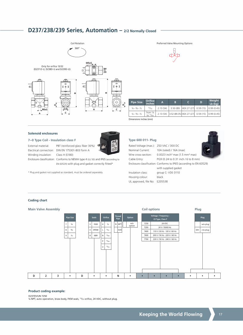
D237/238/239 Series, Automation – 2/2 Normally Closed
Specifications
Function (single acting)
A
P
Flow direction overseat 1 2
Maximum Viscosity Max. 21cST (3 °E)
Body Material (Std) Brass C37700 (UNS Designation)
Orifice Material1 Stainless Steel AISI 303 (1.4305 EN 10088)
Flange2 Stainless Steel AISI 303 (1.4305 EN 10088)
Tube Stainless Steel AISI 304
Plunger Stainless Steel AISI 430F (1.4106 EN 10088)
Top Stop Stainless Steel AISI 430F (1.4105 EN 10088)
Springs Stainless Steel AISI 302
Seal Material (Std) Foodgrade FKM
Connection Type NPT
Shading Ring Copper
Electrical Characteristics3
StandardCoil Voltage DC (=)
24 V
StandardCoil Voltage AC 50 Hz (~)
24 V, 110 V, 200 V, 230 V
StandardCoil Voltage AC 60 Hz (~)
24 V, 120 V, 220 V, 240 V
Voltage Tolerance +10% to -15% (AC)
+10% to -5% (DC)
Duty Cycle 100% ED
Enclosure ClassificationNEMA type 4 (UL 50) and IP65 (EN 60529)
with plug and gasket correctly fitted *
Electrical Connection to EN 175301 - 803 - A (ex DIN 43650)
Coil Insulation Class 155 (F) to EN 60730-1
Power Rating(Standard)
AC 18 VA (holding)
AC 36 VA (inrush)
DC 14 W
Seal Material6 and Media Temperature Range
Media
Ambient Temperature Range
Min Max
FKM 14 °F to 266 °F(-10 °C to +130 °C)
Water, oil, air 14 °F(-10 °C)
122 °F(+50 °C)
EPDM 14 °F to 248 °F(-10 °C to +120 °C)
Water, hot water 14 °F(-10 °C)
122 °F(+50 °C)
NBR 14 °F to 194 °F(-10 °C to +90 °C)
Water, oil, air 14 °F(-10 °C)
122 °F(+50 °C)
6 See corrosion reference guide and sealing solutions for material compatability.
Pipe Size
Cv(gpm)
Kv(m3/h)
OPD psi (bar) Orifice inches(mm)
Seal Material
Valve CodeAC
Voltages DC
Voltages
¼ 1.47 1.260 - 5.8(0 - 0.4)
0 - 2.9(0 - 0.2)
13/32 (10.5)
FKMEPDMNBR
D237DVUN4
D237DEUN4
D237DBUN4
³/8 1.76 1.500 - 5.8(0 - 0.4)
0 - 2.9(0 - 0.2)
13/32 (10.5)
FKMEPDMNBR
D238DVUN4
D238DEUN4
D238DBUN4
1/2 1.76 1.500 - 5.8(0 - 0.4)
0 - 2.9(0 - 0.2)
13/32 (10.5)
FKMEPDMNBR
D239DVUN4
D239DEUN4
D239DBUN4
³/8 0.42 0.360 - 116
(0 - 8)
0 - 73(0 - 5)
5/32
(4.0)
FKMEPDMNBR
D238DVLN5
D238DELN5
D238DBLN5
³/8 0.53 0.450 - 73(0 - 5)
0 - 29(0 - 2)
13/64
(5.0)
FKMEPDMNBR
D238DVNN5
D238DENN5
D238DBNN5
³/8 0.60 0.510 - 51(0 - 3.5)
0 - 16(0 - 1.1)
15/64
(6.0)
FKMEPDMNBR
D238DVPN5
D238DEPN5
D238DBPN5
1/2 0.32 0.270 - 247(0 - 17)
0 - 174(0 - 12)
¹/8
(3.0)
FKMEPDMNBR
D239DVHN5
D239DEHN5
D239DBHN5
1/2 0.42 0.360 - 116
(0 - 8)
0 - 73(0 - 5)
5/32
(4.0)
FKMEPDMNBR
D239DVLN5
D239DELN5
D239DBLN5
1/2 0.53 0.450 - 73(0 - 5)
0 - 29(0 - 2)
13/64
(5.0)
FKMEPDMNBR
D239DVNN5
D239DENN5
D239DBNN5
1/2 0.60 0.510 - 51(0 - 3.5)
0 - 16(0 - 1.1)
15/64
(6.0)
FKMEPDMNBR
D239DVPN5
D239DEPN5
D239DBPN5
Features and Benefits
• Direct Acting
• Robust construction for industrial applications
• Stainless steel AISI 430F operators with low residual magnetism
• Choice of high quality seal materials
• Response time 5 to 25 ms
Options Available
Valve Options (see coding chart)
G parallel thread (ISO 228-1)
1 Not for D237D-U, D238D-U and D239D-U.2 D237D-U, D238D-U and D239D-U is carries an additional flange HEX 30 mm
in Brass between body and flange tube, see dimensional drawing on the left (on page 39).
3 These coils are not UL approved.
4 Body as D264/265/266 (on pages 100, 101).5 Same flange tube as D262/263 (on pages 28, 29), see dimensional drawing on the right (on page 39).
A4US
US
A4
US A4
US
A4
A4 US
US
A4
US
A4
A4 US
Keeping the World Flowing 17
Voltage / Frequency -
CE Type, Class F
7250 24 VDC
7200 24 V / 50/60 Hz
7400 110 V / 50 Hz - 120 V / 60 Hz
7600 200 V / 50 Hz - 220 V / 60 Hz
7700 230 V / 50 Hz - 240 V / 60 Hz
Thread Pipe
N NPT
GAS
Orifice
H ¹/8
L 5/32
N 13/64
P 15/64
U 13/32
Option
w/o option
Seals
V FKM
E EPDM
B NBR
Pipe Size Orifice inches A B C D
WeightLb (kg)
¼ - ³/8 - 1/2 13/32 2.13 (54) 3.50 (89) HEX 27 (27) 0.59 (15) 0.99 (0.45)
¼ - ³/8 - 1/2from ¹/8to 15/64
2.13 (54) 3.52 (89.35) HEX 27 (27) 0.59 (15) 0.99 (0.45)
Dimensions inches (mm)
Preferred Valve Mounting Options
Pipe Size
7 1/4
8 ³/8
9 1/2
Plug
w/o plug
0A1 c/w plug
Coil options Plug
Product coding example:D237DVUN 7250 1/4 NPT, auto operation, brass body, FKM seals, 13/32 orifice, 24 VDC, without plug.
Main Valve Assembly
D 2 3 • D • • N • • • • • • • •
Coding chart
Solenoid enclosures
D237/238/239 Series, Automation – 2/2 Normally Closed
Type 600 011- Plug
Rated Voltage (max.): 250 VAC / 300 DC
Nominal Current: 10A (rated) / 16A (max)
Wire cross-section: 0.0023 inch² max (1.5 mm² max)
Cable Entry: PG9 (0.24 to 0.31 inch / 6 to 8 mm)
Enclosure classification: Conforms to IP65 (according to EN 60529)
with supplied gasket
Insulation class: group C- VDE 0110
Housing colour: black
UL approved, file No: E205538
Only for orifice 13/32(D237-D-U, D238D-U and D239D-U):
360º
Coil Rotation
7--0 Type Coil - Insulation class F
External material: PBT (reinforced glass fiber 30%)
Electrical connection: DIN EN 175301-803 form A
Winding insulation: Class H (E180)
Enclosure classification: Conforms to NEMA type 4 (UL 50) and IP65 (according to
EN 60529) with plug and gasket correctly fitted*
* Plug and gasket not supplied as standard, must be ordered separately.

A4US
US
A4
US A4
US
A4
A4 US
US
A4
US
A4
A4 US
Solenoid Valves18
D884/885/886 Series, General Purpose – 2/2 Normally Closed
Features and Benefits
• Pilot operated with assisted lift
• Robust construction for industrial applications
• Stainless steel AISI 430F operators with low residual magnetism
• High quality seal materials
• Response time 50 to 500 ms
Specifications
Function (single acting)
Flow direction overseat 1 2
Maximum Viscosity Max. 21cST (3 °E)
Body Material (Std) Brass C37700 (UNS Designation)
Flange1 Stainless Steel AISI 303 (1.4305 EN 10088)
Tube Stainless Steel AISI 304
Plunger Stainless Steel AISI 430F (1.4106 EN 10088)
Top Stop Stainless Steel AISI 430F (1.4105 EN 10088)
Springs Stainless Steel AISI 302
Seal Material (Std) FKM
Connection Type NPT
Shading Ring Copper
Electrical Characteristics
Coil Voltage DC (=)24 V
Coil Voltage AC 50 Hz (~)24 V, 110 V, 230 V
Coil Voltage AC 60 Hz (~)120 V, 240 V
Voltage Tolerance +10% to -15% (AC)
+10% to -5% (DC)
Duty Cycle 100% ED
Enclosure ClassificationNEMA type 4 (UL 50) and IP65 (EN 60529)
with plug and gasket correctly fitted *
Electrical Connection to EN 175301 - 803 - A (ex DIN 43650)
Coil Insulation Class 155 (F) to UL429 and to EN 60730-1
Power Rating
( Coils)
AC 15 VA (holding)
AC 30 VA (inrush)
DC 10 W
Pipe Size
Cv(gpm)
Kv(m3/h)
OPD psi (bar) Orifice inches(mm)
Seal Material
Valve CodeAC
Voltages DC
Voltages
¼ 1.47 1.26
0 - 232(0 - 16)
0 - 44(0 - 3)
13/32
(10.5)
FKM D884DVUN
3/8 1.68 1.44 FKM D885DVUN
1/2 1.76 1.50 FKM D886DVUN
A
P
Options Available
Valve Options (see coding chart)
G parallel thread (ISO 228-1)
Silver shading ring
CE coils, power DC 14W - AC 18 VA2
Seal Material3 and Media Temperature Range
Media
Ambient Temperature Range
Min Max
FKM 14 °F to 266 °F(-10 °C to +130 °C)
Water, oil, air 14 °F(-10 °C)
122 °F(+50 °C)
3 See corrosion reference guide and sealing solutions for material compatability.
1 This valve carries an additional flange HEX 30 mm in Brass C37700 betweenbody and flange tube.
2 Pressure ratings of valves fitted with CE coils may be higher than with UL coils(coils specifications on page 157).

A4US
US
A4
US A4
US
A4
A4 US
US
A4
US
A4
A4 US
Keeping the World Flowing 19
Thread Pipe
N NPT
GAS
Voltage / Frequency -
Type, Class F
725R 24 VDC
720R 24 V / 50 Hz
740R 110 V / 50 Hz - 120 V / 60 Hz
770R 230 V / 50 Hz - 240 V / 60 Hz
Voltage / Frequency -
CE Type, Class F
7250 24 VDC
7200 24 V / 50/60 Hz
7400 110 V / 50 Hz - 120 V / 60 Hz
7600 200 V / 50 Hz - 220 V / 60 Hz
7700 230 V / 50 Hz - 240 V / 60 Hz
Option
ASilver
shading ring
w/o option
Pipe Size A B C D Weight Lb (kg)
¼ 2.13 (54) 3.50 (89) HEX 27 (27) 0.59 (15) 0.99 (0.45)
3/8 - 1/2 2.13 (54) 3.50 (89) HEX 27 (27) 0.59 (15) 0.88 (0.4)
Dimensions inches (mm)
360º
Coil Rotation Preferred Valve Mounting Options
Pipe Size
4 1/4
5 ³/8
6 1/2
Plug
w/o plug
0A1 c/w plug
Coil options Plug
Product coding example:
D884DVUN 725R 1/4 NPT, auto operation, brass body, FKM seals, 13/32 orifice, 24 VDC, without plug.
Main Valve Assembly
D 8 8 • D V U N • • • • • • • •
Coding chart
Solenoid enclosures
D884/885/886 Series, General Purpose – 2/2 Normally Closed
Type 600 011- Plug
Rated Voltage (max.): 250 VAC / 300 DC
Nominal Current: 10A (rated) / 16A (max)
Wire cross-section: 0.0023 inch² max (1.5 mm² max)
Cable Entry: PG9 (0.24 to 0.31 inch / 6 to 8 mm)
Enclosure classification: Conforms to IP65 (according to EN 60529)
with supplied gasket
Insulation class: group C- VDE 0110
Housing colour: black
UL approved, file No: E205538
7--R Type Coil - Insulation class F
Encapsulation material: PET 815ER Rynite®
Electrical connection: DIN EN 175301-803 form A
Winding insulation: Class H (P180)
Enclosure classification: Conforms to NEMA type 4 (UL 50) and IP65 (according to
EN 60529) with plug and gasket correctly fitted*
UL approved, file No: E193928
* Plug and gasket not supplied as standard, must be ordered separately.

A4US
US
A4
US A4
US
A4
A4 US
US
A4
US
A4
A4 US
Solenoid Valves20
D264/265/266 Series, Compressed Air and General Purpose – 2/2 Normally Closed
Features and Benefits
• Pilot operated
• Robust construction for industrial applications
• Stainless steel AISI 430F operators with low residual magnetism
• Choice of high quality seal materials
• Response time 50 to 500 ms
Specifications
Function (single acting)
Flow direction overseat 1 2
Maximum Viscosity max. 21cST (3 °E)
Body Material (Std) Brass C37700 (UNS Designation)
Flange1 Stainless Steel AISI 303 (1.4305 EN 10088)
Tube Stainless Steel AISI 304
Plunger Stainless Steel AISI 430F (1.4106 EN 10088)
Top Stop Stainless Steel AISI 430F (1.4105 EN 10088)
Springs Stainless Steel AISI 302
Seal Material (Std) NBR
Connection Type NPT
Shading Ring Copper
Electrical Characteristics
Coil Voltage DC (=)24 V
Coil Voltage AC 50 Hz (~)24 V, 110 V, 230 V
Coil Voltage AC 60 Hz (~)120 V, 240 V
Voltage Tolerance +10% to -15% (AC)
+10% to -5% (DC)
Duty Cycle 100% ED
Enclosure ClassificationNEMA type 4 (UL 50) and IP65 (EN 60529)
with plug and gasket correctly fitted *
Electrical Connection to EN 175301 - 803 - A (ex DIN 43650)
Coil Insulation Class 155 (F) to UL429 and to EN 60730-1
Power Rating
( Coils)
AC 15 VA (holding)
AC 30 VA (inrush)
DC 10 W
Pipe Size
Cv(gpm)
Kv(m3/h)
OPD psi (bar) Orifice inches(mm)
Seal Material
Valve CodeAC
Voltages DC
Voltages
¼ 1.47 1.26
1.5 - 232(0.1- 16)
1.5 - 102(0.1- 7)
13/32
(10.5)
NBR
FKM
EPDM
D264DBUN
D264DVUN
D264DEUN
3/8 1.68 1.44
NBR
FKM
EPDM
D265DBUN
D265DVUN
D264DEUN
1/2 1.76 1.50
NBR
FKM
EPDM
D266DBUN
D266DVUN
D264DEUN
A
P
Options Available
Valve Options (see coding chart)
G parallel thread (ISO 228-1)
CE coils, power DC 14W - AC 18 VA
Seal Material2 and Media Temperature Range
Media
Ambient Temperature Range
Min Max
NBR 14 °F to 194 °F(-10 °C to +90 °C)
Water, oil, air 14 °F(-10 °C)
122 °F(+50 °C)
FKM 14 °F to 266 °F(-10 °C to +130 °C)
Water, oil, air 14 °F(-10 °C)
122 °F(+50 °C)
EPDM 14 °F to 248 °F(-10 °C to +120 °C)
Water, hot water 14 °F(-10 °C)
122 °F(+50 °C)
2 See corrosion reference guide and sealing solutions for material compatability.
1 This valve carries an additional flange HEX 30 mm in Brass C37700 between body and flange tube.

A4US
US
A4
US A4
US
A4
A4 US
US
A4
US
A4
A4 US
Keeping the World Flowing 21
Thread Pipe
N NPT
GAS
Voltage / Frequency -
Type, Class F
725R 24 VDC
720R 24 V / 50 Hz
740R 110 V / 50 Hz - 120 V / 60 Hz
770R 230 V / 50 Hz - 240 V / 60 Hz
Voltage / Frequency -
CE Type, Class F
7250 24 VDC
7200 24 V / 50/60 Hz
7400 110 V / 50 Hz - 120 V / 60 Hz
7600 200 V / 50 Hz - 220 V / 60 Hz
7700 230 V / 50 Hz - 240 V / 60 Hz
Option
w/o option
Seals
B NBR
V FKM
E EPDM
Pipe size A B C D Weight Lb (kg)
¼ 2.13 (54) 3.50 (89) HEX 27 (27) 0.59 (15) 0.99 (0.45)
3/8 - 1/2 2.13 (54) 3.50 (89) HEX 27 (27) 0.59 (15) 0.88 (0.4)
Dimensions inches (mm)
360º
Coil Rotation Preferred Valve Mounting Options
Pipe Size
4 1/4
5 ³/8
6 1/2
Plug
w/o plug
0A1 c/w plug
Coil options Plug
Product coding example:D264DBUN 7250 1/4 NPT, auto operation, brass body, NBR seals, 13/32 orifice, 24 VDC, without plug.
Main Valve Assembly
D 2 6 • D • U N • • • • • • • •
Coding chart
Solenoid enclosures
D264/265/266 Series, Compressed Air and General Purpose – 2/2 Normally Closed
Type 600 011- Plug
Rated Voltage (max.): 250 VAC / 300 DC
Nominal Current: 10A (rated) / 16A (max)
Wire cross-section: 0.0023 inch² max (1.5 mm² max)
Cable Entry: PG9 (0.24 to 0.31 inch / 6 to 8 mm)
Enclosure classification: Conforms to IP65 (according to EN 60529)
with supplied gasket
Insulation class: group C- VDE 0110
Housing colour: black
UL approved, file No: E205538
7--R Type Coil - Insulation class F
Encapsulation material: PET 815ER Rynite®
Electrical connection: DIN EN 175301-803 form A
Winding insulation: Class H (P180)
Enclosure classification: Conforms to NEMA type 4 (UL 50) and IP65 (according to
EN 60529) with plug and gasket correctly fitted*
UL approved, file No: E193928
* Plug and gasket not supplied as standard, must be ordered separately.

A4US
US
A4
US A4
US
A4
A4 US
US
A4
US
A4
A4 US
Solenoid Valves22
D187/188/189/190/192/293 - C D187/188/189/190/192/293 Series,General Purpose – 2/2 Normally Closed
Features and Benefits
• Pilot operated with linked diaphragm
• Robust construction for industrial applications
• Zero pressure rated
• Stainless steel AISI 430F operators with low residual magnetism
• Choice of high quality seal materials
• Speed control screw as standard for type D293 and C D293
• Response time 50 to 500 ms
Specifications
Function (single acting)
A
P
Flow direction overseat 1 2
Maximum Viscosity Max. 21cST (3 °E)
Body Material (Std) Brass C37700 (UNS Designation)
Flange Stainless Steel AISI 303 (1.4305 EN 10088)
Tube Stainless Steel AISI 304
Plunger Stainless Steel AISI 430F (1.4106 EN 10088)
Top Stop Stainless Steel AISI 430F (1.4105 EN 10088)
Springs Stainless Steel AISI 302
Seal Material (Std) NBR
Connection Type NPT
Shading Ring Copper
Electrical Characteristics
StandardCoil Voltage DC (=)
24 V
Coil Voltage AC 50 Hz (~)24 V, 110 V, 230 V
Coil Voltage AC 60 Hz (~)120 V, 240 V
Voltage Tolerance +10% to -15% (AC)
+10% to -5% (DC)
Duty Cycle 100% ED
Enclosure ClassificationNEMA type 4 (UL 50) and IP65 (EN 60529)
with plug and gasket correctly fitted *
Electrical Connection to EN 175301 - 803 - A (ex DIN 43650)
Coil Insulation Class 155 (F) to UL429 and to EN 60730-1
Power Rating
( Coils)
AC 15 VA (holding)
AC 30 VA (inrush)
DC 10 W
Options Available
Pipe Size
Cv(gpm)
Kv(m3/h)
OPD psi (bar) Orifice inches(mm)
Seal Material
Valve CodeAC
Voltages DC
Voltages
¼ 3.51 3.00
0 - 232(0 - 16)
-
19/32 (15)
NBRFKM
EPDM
D187DBWND187DVWND187DEWN
3/8 4.21 3.60 19/32 (15)
NBRFKM
EPDM
D188DBWND188DVWND188DEWN
1/2 4.56 3.90 19/32 (15)
NBRFKM
EPDM
D189DBWND189DVWND189DEWN
3/4 5.62 4.80 19/32 (15)
NBRFKM
EPDM
D190DBWND190DVWND190DEWN
1compact
5.97 5.10 19/32 (15)
NBRFKM
EPDM
D192DBWND192DVWND192DEWN
1 9.83 8.40 63/64 (25)NBRFKM
EPDM
D293DBYND293DVYND293DEYN
¼ 3.51 3.00
-0 - 7*
(0 - 0.5)
19/32 (15)
NBRFKM
EPDM
C D187DBWN*
C D187DVWN*
C D187DEWN*
3/8 4.21 3.60 19/32 (15)
NBRFKM
EPDM
C D188DBWN*
C D188DVWN*
C D188DEWN*
1/2 4.56 3.90 19/32 (15)
NBRFKM
EPDM
C D189DBWN*
C D189DVWN*
C D189DEWN*
3/4 5.62 4.80 19/32 (15)
NBRFKM
EPDM
C D190DBWN*
C D190DVWN*
C D190DEWN*
1compact
5.97 5.10 19/32 (15)
NBRFKM
EPDM
C D192DBWN*
C D192DVWN*
C D192DEWN*
Valve Options (see coding chart)
G parallel thread (ISO 228-1)
Electroless nickel plating
CE coils, power DC 14W - AC 18 VA
Seal Material1 and Media Temperature Range
Media
Ambient Temperature Range
Min Max
NBR 14 °F to 194 °F(-10 °C to +90 °C)
Water, oil, air 14 °F(-10 °C)
122 °F(+50 °C)
FKM 14 °F to 266 °F(-10 °C to +130 °C)
Water, oil, air 14 °F(-10 °C)
122 °F(+50 °C)
EPDM 14 °F to 248 °F(-10 °C to +120 °C)
Water, hot water 14 °F(-10 °C)
122 °F(+50 °C)
1 See corrosion reference guide and sealing solutions for material compatability.
Vacuum Version
See separate datasheet
* Only with CE coils: pressure rating 0-6 bar.

A4US
US
A4
US A4
US
A4
A4 US
US
A4
US
A4
A4 US
Keeping the World Flowing 23
Voltage / Frequency -
Type, Class F
725R 24 VDC
720R 24 V / 50 Hz
740R 110 V / 50 Hz - 120 V / 60 Hz
770R 230 V / 50 Hz - 240 V / 60 Hz
Voltage / Frequency -
CE Type, Class F
7250 24 VDC
7200 24 V / 50/60 Hz
7400 110 V / 50 Hz - 120 V / 60 Hz
7600 200 V / 50 Hz - 220 V / 60 Hz
7700 230 V / 50 Hz - 240 V / 60 Hz
Thread Pipe
N NPT
GAS
Valve Type
DAC
version
CDDC
version
Option
KElectroless
nickel plating
w/o option
Seals
B NBR
V FKM
E EPDM
Pipe Size A B C D Weight Lb (kg)
¼ - 1/2 2.95 (75) 4.25 (108) 2.17 (55) 0.55 (14) 1.10 (0.5)
3/4 - 1 compact 3.35 (85) 4.25 (108) 2.17 (55) 0.85 (21.5) 1.76 (0.8)
1 3.94 (100) 4.45 (113) 2.76 (70) 0.85 (21.5) 2.65 (1.2)
Dimensions inches (mm)
360º
Coil Rotation Preferred Valve Mounting Options
Pipe Size
187 1/4
188 ³/8
189 1/2
190 3/4
1921
compact
293 1
Plug
w/o plug
0A1 c/w plug
Coil options
Orifice1
W 19/32
Y 63/64
Plug
Product coding example:D188DBWN 720R 3/8 NPT, auto operation, brass body, NBR seals, 19/32 orifice, 24 V / 50/60 Hz, without plug.
Main Valve Assembly
• • • • D • • N • • • • • • • •
Coding chart
D187/188/189/190/192/293 - C D187/188/189/190/192/293 Series,General Purpose – 2/2 Normally Closed
Solenoid enclosures
Type 600 011- Plug
Rated Voltage (max.): 250 VAC / 300 DC
Nominal Current: 10A (rated) / 16A (max)
Wire cross-section: 0.0023 inch² max (1.5 mm² max)
Cable Entry: PG9 (0.24 to 0.31 inch / 6 to 8 mm)
Enclosure classification: Conforms to IP65 (according to EN 60529)
with supplied gasket
Insulation class: group C- VDE 0110
Housing colour: black
UL approved, file No: E205538
1 DN 63/64 for D293 and C D293 only.
7--R Type Coil - Insulation class F
Encapsulation material: PET 815ER Rynite®
Electrical connection: DIN EN 175301-803 form A
Winding insulation: Class H (P180)
Enclosure classification: Conforms to NEMA type 4 (UL 50) and IP65 (according to
EN 60529) with plug and gasket correctly fitted*
UL approved, file No: E193928
* Plug and gasket not supplied as standard, must be ordered separately.

A4US
US
A4
US A4
US
A4
A4 US
US
A4
US
A4
A4 US
Solenoid Valves24
B203/204/205/206/222 Series, General Purpose – 2/2 Normally Closed
Features and Benefits
• Pilot operated
• Robust construction for industrial applications
• Stainless steel AISI 430F operators with low residual magnetism
• Choice of high quality seal materials
• Response time 50 to 500 ms
Options Available
Seal Material1 and Media Temperature Range
Media
Ambient Temperature Range
Min Max
NBR 14 °F to 194 °F(-10 °C to +90 °C)
Water, oil, air 14 °F(-10 °C)
122 °F(+50 °C)
FKM 14 °F to 266 °F(-10 °C to +130 °C)
Water, oil, air 14 °F(-10 °C)
122 °F(+50 °C)
EPDM 14 °F to 248 °F(-10 °C to +120 °C)
Water, hot water 14 °F(-10 °C)
122 °F(+50 °C)
1 See corrosion reference guide and sealing solutions for material compatability.
Pipe Size
Cv(gpm)
Kv(m3/h)
OPD psi (bar) Orifice inches(mm)
Seal Material
Valve CodeAC
Voltages DC
Voltages
¼ 1.83 1.56
4 - 232(0.3 - 16)
4 - 232(0.3 - 16)
33/64
(13)
NBR
FKM
EPDM
B203DBZN
B203DVZN
B203DEZN
³/8 3.86 3.30
NBR
FKM
EPDM
B204DBZN
B204DVZN
B204DEZN
1/2 4.42 3.78
NBR
FKM
EPDM
B205DBZN
B205DVZN
B205DEZN
3/4 compact
7.02 6.0053/64
(21)
NBR
FKM
EPDM
B206DBXN
B206DVXN
B206DEXN
3/4 9.83 8.4063/64
(25)
FNBR
FKM
EPDM
B206DBYN
B206DVYN
B206DEYN
1 11.23 9.60
NBR
FKM
EPDM
B222DBYN
B222DVYN
B222DEYN
Valve Options (see coding chart)
G parallel thread (ISO 228-1)
Manual override
Electroless nickel plating treatment
Speed control screw (on DN25 only)
CE coils, power DC 7W - AC 10 VA
A
P
Specifications
Function (single acting)
A
P
Flow direction overseat 1 2
Maximum Viscosity Max. 21cST (3 °E)
Body Material (Std) Brass C37700 (UNS Designation)
Flange Stainless Steel AISI 303 (1.4305 EN 10088)
Tube Stainless Steel AISI 304
Plunger and Top Stop Stainless Steel AISI 430F or equivalent
Springs Stainless Steel AISI 302
Seal Material (Std) NBR
Connection Type NPT
Shading Ring Copper
Electrical Characteristics
Coil Voltage DC (=)24 V
Coil Voltage AC 50 Hz (~)24 V, 110 V, 230 V
Coil Voltage AC 60 Hz (~)120 V, 240 V
Voltage Tolerance +10% to -15% (AC)
+10% to -5% (DC)
Duty Cycle 100% ED
Enclosure ClassificationNEMA type 4 (UL 50) and IP65 (EN 60529)
with plug and gasket correctly fitted *
Electrical Connection to industrial form B
Coil Insulation Class 155 (F) to UL429 and to EN 60730-1
Power Rating
( Coils)
AC 9 VA (holding)AC 14 VA (inrush)
DC 6W

A4US
US
A4
US A4
US
A4
A4 US
US
A4
US
A4
A4 US
Keeping the World Flowing 25
B203/204/205/206/222 Series, General Purpose – 2/2 Normally Closed
Thread Pipe
N NPT
GAS
Voltage / Frequency -
Type, Class F
225R 24VDC
220R 24 V / 50 Hz
240R 110 V / 50 Hz - 120 V / 60 Hz
270R 230 V / 50 Hz - 240 V / 60 Hz
Voltage / Frequency -
CE Type, Class F
2250 24 VDC
2200 24 V / 50/60 Hz
2400 110 V / 50 Hz - 120 V / 60 Hz
2600 200 V / 50 Hz - 220 V / 60 Hz
2700 230 V / 50 Hz - 240 V / 60 Hz
Pipe Size
03 1/4
04 3/8
05 1/2
063/4
(compact)
06 3/4
22 1
360º
Coil Rotation
Product coding example:B203DBZN 225R 1/4 NPT, auto operation, brass body, NBR seals, 33/64 orifice, 24 VDC, without plug.
Preferred Valve Mounting Options
Main Valve Assembly Coil options
Plug
w/o plug
0B1 c/w plug
Option
MManual
Override
KElectroless
nickelplating
VSpeed control screw2
w/o option
Orifice1
Z 33/64
X 53/64
Y 63/64
Seals
B NBR
V FKM
E EPDM
B 2 • • D • • N • • • • • • • •
Coding chart
Dimensions inches (mm)
Plug
Pipe Size A B C D Weight Lb (kg)
¼ - 3/8 - 1/2 2.64 (67) 3.54 (90) 1.80 (45.6) 0.59 (15) 0.88 (0.4)
3/4 compact 3.23 (82) 4.13 (105) 2.03 (51.6) 0.80 (20.25) 1.32 (0.6)
3/4 to 1 3.78 (96) 4.53 (115) 2.83 (72) 0.91 (23) 2.65 (1.2)
Solenoid enclosures
1 DN 33/64 only for B203/204/205, DN 53/64 only for B206 compact, DN 63/64 only for B206 and B222.2 Speed control screw available on B206D-YN and B222D-YN.
Type 600 001- Plug
Rated Voltage (max.): 250 VAC / 300 DC
Nominal Current: 10A (rated) / 16A (max)
Wire cross-section: 0.0023 inch² max (1.5 mm² max)
Cable Entry: PG9 (0.24 to 0.31 inch / 6 to 8 mm)
Enclosure classification: Conforms to IP65 (according to EN 60529)
with supplied gasket
Insulation class: group C- VDE 0110
Housing colour: black
UL approved, file No: E205538
2--R Type Coil - Insulation class F
External material: PET 815ER Rynite®
Electrical connection: Industrial form B
Winding insulation: Class H (P180)
Enclosure classification: Conforms to NEMA type 4 (UL 50) and IP65 (according to
EN 60529) with plug and gasket correctly fitted*
UL approved, file No: E193928
* Plug and gasket not supplied as standard, must be ordered separately.

A4US
US
A4
US A4
US
A4
A4 US
US
A4
US
A4
A4 US
Solenoid Valves26
D223/224/225 Series, General Purpose – 2/2 Normally Closed
Features and Benefits
• Pilot operated
• Robust construction for industrial applications
• Stainless steel AISI 430F operators with low residual magnetism
• Choice of high quality seal materials
• Speed control screw as standard
• Response time 50 to 500 ms
Specifications
Function (single acting)
A
P
Flow direction overseat 1 2
Maximum Viscosity Max. 21cST (3 °E)
Body Material (Std) Brass C37700 (UNS Designation)
Flange Stainless Steel AISI 303 (1.4305 EN 10088)
Tube Stainless Steel AISI 304
Plunger Stainless Steel AISI 430F (1.4106 EN 10088)
Top Stop Stainless Steel AISI 430F (1.4105 EN 10088)
Springs Stainless Steel AISI 302
Seal Material (Std) NBR
Connection Type NPT
Shading Ring Copper
Electrical Characteristics
Coil Voltage DC (=)24 V
Coil Voltage AC 50 Hz (~)24 V, 110 V, 230 V
Coil Voltage AC 60 Hz (~)120 V, 240 V
Voltage Tolerance +10% to -15% (AC)
+10% to -5% (DC)
Duty Cycle 100% ED
Enclosure ClassificationNEMA type 4 (UL 50) and IP65 (EN 60529)
with plug and gasket correctly fitted *
Electrical Connection to EN 175301 - 803 - A (ex DIN 43650)
Coil Insulation Class 155 (F) to UL429 and to EN 60730-1
Power Rating
( Coils)
AC 15 VA (holding)
AC 30 VA (inrush)
DC 10 W
Options Available
Pipe Size
Cv(gpm)
Kv(m3/h)
OPD psi (bar) Orifice inches(mm)
Seal Material
Valve CodeAC
Voltages DC
Voltages
1 ¼ 25.97 22.20
7 - 232(0.5 - 16)
7 - 232(0.5 - 16)
1 37/64
(40)
NBR
FKM
EPDM
D223DBKN
D223DVKN
D223DEKN
1 1/2 28.08 24.001 37/64
(40)
NBR
FKM
EPDM
D224DBKN
D224DVKN
D224DEKN
2 37.91 32.402
(50)
NBR
FKM
EPDM
D225DBJN
D225DVJN
D225DEJN
Valve Options (see coding chart)
G parallel thread (ISO 228-1)
Electroless nickel plating
CE coils, power DC 14W - AC 18 VA
Seal Material1 and Media Temperature Range
Media
Ambient Temperature Range
Min Max
NBR 14 °F to 194 °F(-10 °C to +90 °C)
Water, oil, air 14 °F(-10 °C)
122 °F(+50 °C)
FKM 14 °F to 266 °F(-10 °C to +130 °C)
Water, oil, air 14 °F(-10 °C)
122 °F(+50 °C)
EPDM 14 °F to 248 °F(-10 °C to +120 °C)
Water, hot water 14 °F(-10 °C)
122 °F(+50 °C)
1 See corrosion reference guide and sealing solutions for material compatability.
Vacuum Version
See separate datasheet

A4US
US
A4
US A4
US
A4
A4 US
US
A4
US
A4
A4 US
Keeping the World Flowing 27
Thread Pipe
N NPT
GAS
Option
KElectroless
nickel plating
w/o option
Seals
B NBR
V VKM
E EPDM
Pipe Size A B C D Weight Lb (kg)
1 ¼ - 1 1/2 5.51 (140) 5.51 (140) 3.78 (96) 1.24 (31.5) 6.17 (2.8)
2 6.57 (167) 6.22 (158) 4.41 (112) 1.54 (39) 8.60 (3.9)
Dimensions inches (mm)
360º
Coil Rotation Preferred Valve Mounting Options
Pipe Size
23 1 1/4
24 1 1/2
25 2
Plug
w/o plug
0A1 c/w plug
Coil options
Orifice1
K1
37/64
J 2
Plug
1 DN 1 37/64 only for D223 and D224, DN 2 only for D225.
Product coding example:D223DBKN 725R 1 1/4 NPT, auto operation, brass body, NBR seals, 40 mm orifice, 24 VDC, without plug.
Main Valve Assembly
D 2 • • D • • N • • • • • • • •
Coding chart
Solenoid enclosures
D223/224/225 Series, General Purpose – 2/2 Normally Closed
Type 600 011- Plug
Rated Voltage (max.): 250 VAC / 300 DC
Nominal Current: 10A (rated) / 16A (max)
Wire cross-section: 0.0023 inch² max (1.5 mm² max)
Cable Entry: PG9 (0.24 to 0.31 inch / 6 to 8 mm)
Enclosure classification: Conforms to IP65 (according to EN 60529)
with supplied gasket
Insulation class: group C- VDE 0110
Housing colour: black
UL approved, file No: E205538
Voltage / Frequency -
Type, Class F
725R 24 VDC
720R 24 V / 50 Hz
740R 110 V / 50 Hz - 120 V / 60 Hz
770R 230 V / 50 Hz - 240 V / 60 Hz
Voltage / Frequency -
CE Type, Class F
7250 24 VDC
7200 24 V / 50/60 Hz
7400 110 V / 50 Hz - 120 V / 60 Hz
7600 200 V / 50 Hz - 220 V / 60 Hz
7700 230 V / 50 Hz - 240 V / 60 Hz
7--R Type Coil - Insulation class F
Encapsulation material: PET 815ER Rynite®
Electrical connection: DIN EN 175301-803 form A
Winding insulation: Class H (P180)
Enclosure classification: Conforms to NEMA type 4 (UL 50) and IP65 (according to
EN 60529) with plug and gasket correctly fitted*
UL approved, file No: E193928
* Plug and gasket not supplied as standard, must be ordered separately.

A4US
US
A4
US A4
US
A4
A4 US
US
A4
US
A4
A4 US
Solenoid Valves28
UACD Series – 2/2 Normally Closed
Features and Benefits
• Two way shut-off valves for the control of gases and liquids compatible with max viscosity and materials
• Zero bar minimum operating pressure
• Satisfy all relevant EC directives
• Robust Valve Design
• Diaphragm Operation
• Fully Ported Orifices for high flow
• Choice of valve body material seals
• Sizes 3/8” - 3/4” approved to BS EN 60730 - 2 -8 for household use when used with EPDM seals
• Response time 1” 15-60 ms
• Response time 2” 60-120 ms
• EN264 for fuel oils
• Tested in accordance with BS-EN 12266-1
• Suitable for vacuum applications when fitted with Viton seals (10-3 TORR) - 0 rated models only
Specifications
Mode of Operation
Normally Closed, energise to openOut (2)
In (1)
Maximum Viscosity 115 SSU
3/8” - 1” Body Material (Std)
Brass (Std) or Stainless Steel option
11/4” - 2” Body Material (Std)
Bronze (Std)
Flange Tube Stainless Steel
Plunger and top stop Stainless Steel
Springs Stainless Steel
Seal Material Nitrile (BunaN) (Std) other options available
Connection Type NPT
Shading Ring Copper (std), Silver (stainless steel option)
Electrical Characteristics
Coil Voltage DC (=) 12 V, 24 V
Coil Voltage AC 60 Hz (~)
24 V, 120 V
Voltage Tolerance +10% or -10%
Duty Cycle 100% ED
Electrical Connection Options
1/2” NPT metal conduit hub with 18” leads (NEMA 2 equivalent protection class)
Coil Insulation Class H
Power Rating 14.5 Watts
Main Valve Body Options
Stainless Steel 316 (up to and including 1")
Manual Override
Oxygen Cleaning (consult factory for product code)
Stainless Steel Tagging (consult factory for product code)
Options Available
2 Pressure assisted to achieve a greater OPD. e.g. code 19G31Z2A1-2F19A.3 P. Max is limited to 675 psi when valve is fitted with an Exd solenoid operator, see separate datasheet.
Port Size
Cv Kv
OPD (psi)P. Max3
psiOrifice (mm)
Weight (lbs)AC
Voltages DC
Voltages
3/8” 3.5 3.0 0-150 0-150
725
16.0 2
1/2” 4.9 4.2 0-150 0-150 16.0 2
3/4” 5.4 4.7 0-150 0-150 16.0 2
1” 8.2 7.0 0-150 0-150 20.0 4.0
1¼” 26.7 23 0-60 - 40.0 6.6
11/2” 26.7 23 0-60 - 40.0 6.6
2” 30.16 26 0-60 - 40.0 6.6
1¼”2 26.7 23 5-150 5-150 40.0 6.6
11/2”2 26.7 23 5-150 5-150 40.0 6.6
2”2 30.2 26 5-150 5-150 40.0 6.6
Solenoid Enclosure
Protection Class
EExd T6 (NEMA 6 equivalent)
See separate datasheetEExd T4
(NEMA 6 equivalent)
1. Select the required flow.
2. Note the corresponding pressure drop.
3. Based on where the two points intersect select the most appropriate model.
How to use the flow chart
Seal Material1 and Media Temp. Range
Ambient Temperature Range
Min Max
Nitrile (14 ºF to +176 ºF) 14 ºF 122 ºF
EPDM (-58 ºF to +248 ºF) 14 ºF 122 ºF
Viton (-4 ºF to +302 ºF) 14 ºF 122 ºF
1 See corrosion reference guide and sealing solutions for material compatability.
Pressure Drop
(PSI)
Water Flow (L/Min)
Pres
sure
Dro
p (B
ar)
Water Flow (GPM)2.2
1
0.110 100 1000
5 10 20 40 80 160
15
10
5
3
1.5
2" v
alve
- 40
.0 m
m o
rifice
1¼"
& 1
1/2"
valv
e - 4
0.0
mm
orifi
ce
3/4"
valv
e - 1
6.0
mm
orifi
ce1"
val
ve -
20.0
mm
orifi
ce
1/2"
valv
e - 1
6.0
mm
orifi
ce
3 /8"
valv
e - 1
6.0
mm
orifi
ce

A4US
US
A4
US A4
US
A4
A4 US
US
A4
US
A4
A4 US
Keeping the World Flowing 29
UACD Series – 2/2 Normally Closed
360º
Coil Rotation Preferred Valve Mounting Options
Dimensions given in inchesStainless steel option dimensions vary from table - consult factory.
Port size A B C D
3/8” - 3/4” 23/4” 37/16” 3" 43/8”
1” 33/8” 37/16” 3" 53/8”
1¼” - 2” 53/8” 45/8” 43/4” 57/8"
Dimensions
S4 Type enclosure protection class IP50
External material: Pressed steel powder coated
Electrical entry: 1/2” NPT metal conduit hub with 18” leads (NEMA 2 equivalent protection class)
Winding Insulation: Class H
Solenoid enclosures
Product coding example:
17C31Z1B1-2H29A: UACD Series 3/8” NPT, Auto, Brass body, EPDM seals, 120 V / 60 Hz 1/2” NPT electrical connection UL/CSA approval.
Main Valve Assembly Coil options
Enclosure
2
S4 type enclosure -metal can (IP50) UL
Approved4
Approval
AUL4/CSA
8Non UL
Voltage / Frequency
F1 24 VDC
F4 12 VDC
H1 24 V / 60 Hz
H2 120 V / 60 Hz
Electrical Connection
91/2” NPT
2 •• 9 •
Valve Body Conn. Size
C 3/8”
D 1/2”
E 3/4”
F 1”
G 11/4”
H 11/2”
J 2”
Operation
1 AUTO
2 MANUAL OVERIDE
Conn. Type
3 NPT
Model
17 AC VOLTAGE
18 DC3 VOLTAGE
19
Pressure assisted option
11/4"to 2"
Seals
A Nitrile
B EPDM
C VITON
Style
1 Standard
Body Material
1
Brass (standard on valves up to and
including 1”)
2
Bronze (standard on valves above 1”)
5
316 Stainless Steel (option available up to
and inc 1”)
•• • 3 • Z • • 1 -
Orifice (mm)
Z Default
3 1¼” to 2" '0' pressure rated options are not available in DC voltages.4 24 V / 60 Hz and 120 V 60 Hz only.
A
D
C
B
Coding chart

A4US
US
A4
US A4
US
A4
A4 US
US
A4
US
A4
A4 US
Solenoid Valves30
UACP Series – 2/2 Normally Closed
Features and Benefits
• Heavy duty valve design
• Piston operation
• Choice of valve body material and seals
• Wide temperature range capabilities
• Response time up to 1” 40 - 100 ms
• Response time up to 2” 60 - 1000 ms
• Tested in accordance with BS-EN 12266-1
Specifications
Mode of Operation
Normally Closed, energise to open
Out (2)
In (1)
Maximum Viscosity 115 SSU
3/8” - 1” Body Material (Std)
Brass (Std) or Stainless Steel option
11/4” - 2” Body Material (Std)
Bronze (Std)
Flange Tube Stainless Steel
Plunger and top stop Stainless Steel
Springs Stainless Steel
Seal Material Nitrile (BunaN) (Std) other options available
Connection Type NPT
Shading Ring Copper (std), Silver (stainless steel option)
Electrical Characteristics
Coil Voltage DC (=) 12 V, 24 V
Coil Voltage AC 60 Hz (~)
24 V, 120 V
Voltage Tolerance +10% or -10%
Duty Cycle 100% ED
Electrical Connection Options
1/2” NPT metal conduit hub with 18” leads (NEMA 2 equivalent protection class)
Coil Insulation Class H
Power Rating 14.5 Watts
Main Valve Body Options
Stainless Steel 316 (up to and including 1")
Oxygen Cleaning (consult factory for product code)
Stainless Steel Tagging (consult factory for product code)
Options Available
Solenoid Enclosure
Protection Class
EExd T6 (NEMA 6 equivalent)
See separate datasheetEExd T4
(NEMA 6 equivalent)
Port Size
Cv Kv
OPD (psi)P. Max2
psiOrifice (mm)
Weight (lbs)AC
Voltages DC
Voltages
1/2” 4.9 4.2 5-150 5-150
725
16.0 2.8
3/4” 6.3 5.4 5-125 5-125 16.0 2.8
1” 14.5 12.5 5-125 5-125 25.0 5
1¼” 20.9 18 5-125 5-125 30.0 6.8
11/2” 20.9 18 5-125 5-125 30.0 6.8
2” 24.4 21 5-125 5-125 32.0 11.5
1 See corrosion reference guide and sealing solutions for material compatability.
2 P. Max is limited to 675 psi when valve is fitted with an Exd solenoid operator, see separate datasheet.
1. Select the required flow.
2. Note the corresponding pressure drop.
3. Based on where the two points intersect select the most appropriate model.
How to use the flow chart
Seal Material1 and Media Temp. Range
Ambient Temperature Range
Min Max
Nitrile (14 ºF to +176 ºF) 14 ºF 122 ºF
EPDM (-58 ºF to +248 ºF) 14 ºF 122 ºF
Viton (-4 ºF to +302 ºF) 14 ºF 122 ºF
Pressure Drop
(PSI)
Water Flow (L/Min)
Pres
sure
Dro
p (B
ar)
Water Flow (GPM)2.2
1
0.110 100 1000
5 10 20 40 80 160
15
10
5
3
1.5
1¼"
& 1
1/2"
valv
e - 3
0.0
mm
orifi
ce
1" v
alve
- 25
.0 m
m o
rifice
3/4"
vavl
e - 1
6.0
mm
orifi
ce
1/2"
valv
e - 1
6.0
mm
orifi
ce
2" v
alve
- 32
.0 m
m o
rifice

A4US
US
A4
US A4
US
A4
A4 US
US
A4
US
A4
A4 US
Keeping the World Flowing 31
UACP Series – 2/2 Normally Closed
Dimensions given in inches
Dimensions
Preferred Valve Mounting Options
S4 Type enclosure protection class IP50
External material: Pressed steel powder coated
Electrical entry: 1/2” NPT metal conduit hub with 18” leads (NEMA 2 equivalent protection class)
Winding Insulation: Class H
Solenoid enclosures
Product coding example:
22D31Z1A1-2H29A: UACP Series 1/2” NPT, Auto, Brass body, nitrile seals, 120 V / 60 Hz, 1/2” NPT electrical connection UL/CSA approval.
Main Valve Assembly Coil options
Voltage / Frequency
F1 24 VDC
F4 12 VDC
H124 V / 60 Hz
H2120 V / 60 Hz
Electrical connection
91/2” NPT
2 •• 9 A
Valve Body Conn. Size
D 1/2”
E 3/4”
F 1”
G 11/4”
H 11/2”
J 2”
Operation
1 AUTO
Conn. Type
3 NPT
Seals
A Nitrile
B EPDM
C VITON
Style
1 Standard
Model
22 UACP
Body Material
1
Brass (standard on valves up to and
including 1”)
2
Bronze (standard on valves above 1”)
5
316 Stainless Steel (option available up to
and inc 1”)
22 • 3 1 Z • • 1 -
Orifice (mm)
Z Default
Enclosure
2
S4 type enclosure
-metal can
(IP50) UL Approved
Approval
A UL/CSA
Port size A B C D
1/2" - 3/4" 21/2" 41/8" 21/4" 413/16"
1" 41/4" 415/16" 3" 53/4"
11/4" - 11/2" 45/8" 51/4" 31/4" 81/4"
2" 53/4" 53/4" 4" 81/4"
360º
Coil Rotation
BD
A C
Coding chart

A4US
US
A4
US A4
US
A4
A4 US
US
A4
US
A4
A4 US
Solenoid Valves32
Features and Benefits
• Direct Acting
• Robust construction for industrial applications
• Stainless steel AISI 430F operators with low residual magnetism
• Choice of high quality seal materials
• Response time 5 to 25 ms
Specifications
Function (single acting)
A
P
Flow direction overseat 1 2
Maximum Viscosity Max. 21cST (3 °E)
Body Material (Std) Brass C37700 (UNS Designation)
Orifice Material Stainless Steel AISI 303 (1.4305 EN 10088)
Flange Stainless Steel AISI 303 (1.4305 EN 10088)
Tube Stainless Steel AISI 304
Plunger Stainless Steel AISI 430F (1.4106 EN 10088)
Top Stop Stainless Steel AISI 430F (1.4105 EN 10088)
Springs Stainless Steel AISI 302
Seal Material (Std) Foodgrade FKM
Connection Type (Std) Flanged 1.26x1.26 inches
Shading Ring Copper
Electrical Characteristics
Coil Voltage DC (=)24 V
Coil Voltage AC 50 Hz (~)24 V, 110 V, 230 V
Coil Voltage AC 60Hz (~)120 V, 240 V
Voltage Tolerance +10% to -15% (AC)
+10% to -5% (DC)
Duty Cycle 100% ED
Enclosure ClassificationNEMA type 4 (UL 50) and IP65 (EN 60529)
with plug and gasket correctly fitted *
Electrical Connection to EN 175301 - 803 - A (ex DIN 43650)
Coil Insulation Class 155 (F) to UL429 and to EN 60730-1
Power Rating
( Coils)
AC 15 VA (holding)
AC 30 VA (inrush)
DC 10 W
Options Available
Seal Material3 and Media Temperature Range
Media
Ambient Temperature Range
Min Max
FKM 14 °F to 266 °F(-10 °C to +130 °C)
Water, oil, air, 14 °F(-10 °C)
122 °F(+50 °C)
EPDM 14 °F to 248 °F(-10 °C to +120 °C)
Water, hot water 14 °F(-10 °C)
122 °F(+50 °C)
3 See corrosion reference guide and sealing solutions for material compatability.
Pipe Size
Cv(gpm)
Kv(m3/h)
OPD psi (bar)2 Orifice inches(mm)
Seal Material
Valve CodeAC
Voltages DC
Voltages
Flanged 0.09 0.080 - 348(0 - 24)
0 - 348(0 - 24)
¹/16 (1.5)FKM
EPDM
D201DVC
D201DEC
Flanged 0.15 0.130 - 290(0 - 20)
0 - 218(0 - 15)
2.0 (5/64)FKM
EPDM
D201DVE
D201DEE
Flanged 0.24 0.200 - 218(0 - 15)
0 - 189(0 - 13)
2.5 (3/32)FKM
EPDM
D201DVG
D201DEG
Flanged 0.32 0.270 - 189(0 - 13)
0 - 116(0 - 8)
3.0 (¹/8)FKM
EPDM
D201DVH
D201DEH
Valve Options (see coding chart)
Manual override
CE coils power 14W - 18VA1
D201 Series, General Purpose – 2/2 Normally Closed
2 The valve supplied without coil carry a nameplate with pressure ratings marked in bar.
1 Pressure ratings of valves fitted with CE coils may be higher than with UL coils(coils specifications on page 157).

A4US
US
A4
US A4
US
A4
A4 US
US
A4
US
A4
A4 US
Keeping the World Flowing 33
Option
MManual Overide
w/o option
Seals
V FKM
E EPDM
Pipe Size A B C D Weight Lb (kg)
Flanged 1.26 (32) 2.78 (70.6) 0.94 (24) 0.40 (10.25) 0.55 (0.25)
Dimensions inches (mm)
360º
Coil Rotation Preferred Valve Mounting Options
Plug
w/o plug
0A1 c/w plug
Coil options
Orifice
C ¹/16
E 5/64
G ³/32
H ¹/8
Plug
Product coding example:
D201DVC 770R Flanged connection, auto operation, brass body, FKM seals, 1/16 orifice, 230 V / 50 Hz - 240 V / 60 Hz, without plug.
Main Valve Assembly
D 2 0 1 D • • • • • • • • • • •
Coding chart
Solenoid enclosures
D201 Series, General Purpose – 2/2 Normally Closed
4 holes Ø 0.18
supplied with 2 OR 2025 (silicone)
Type 600 011- Plug
Rated Voltage (max.): 250v AC / 300 DC
Nominal Current: 10A (rated) / 16A (max)
Wire cross-section: 0.0023 inch² max (1.5 mm² max)
Cable Entry: PG9 (0.24 to 0.31 inch / 6 to 8mm)
Enclosure classification: Conforms to IP65 (according to EN 60529)
with supplied gasket
Insulation class: group C- VDE 0110
Housing colour: black
UL approved, file No: E205538
Voltage / Frequency -
Type, Class F
725R 24 VDC
720R 24 V / 50 Hz
740R 110 V / 50 Hz - 120 V / 60 Hz
770R 230 V / 50 Hz - 240 V / 60 Hz
Voltage / Frequency -
CE Type, Class F
7250 24 VDC
7200 24 V / 50/60 Hz
7400 110 V / 50 Hz - 120 V / 60 Hz
7600 200 V / 50 Hz - 220 V / 60 Hz
7700 230 V / 50 Hz - 240 V / 60 Hz
7--R Type Coil - Insulation class F
External material: PET 815ER Rynite®
Electrical connection: DIN EN 175301-803 form A
Winding insulation: Class H (P180)
Enclosure classification: Conforms to NEMA type 4 (UL 50) and IP65 (according to
EN 60529) with plug and gasket correctly fitted*
UL approved, file No: E193928
* Plug and gasket not supplied as standard, must be ordered separately

A4US
US
A4
US A4
US
A4
A4 US
US
A4
US
A4
A4 US
Solenoid Valves34
B397 Series, General Purpose – 3/2 Normally Closed
Specifications
Function (single acting)
A
PR
Flow direction underseat 2 1
Maximum Viscosity Max. 21cST (3 °E)
Body Material (Std) Low lead content Brass C46400 (UNS Designation)
Orifice Material Stainless Steel AISI 303 (1.4305 EN 10088)
Tube Stainless Steel AISI 304
Flange Stainless Steel AISI 303 (1.4305 EN 10088)
Plunger Stainless Steel AISI 430F or equivalent
Top Stop Stainless Steel AISI 430F (1.4105 EN 10088)
Springs Stainless Steel AISI 302
Seal Material (Std) Foodgrade FKM
Connection Type NPT
Shading Ring Copper
Electrical Characteristics1
StandardCoil Voltage DC (=)
24 V
StandardCoil Voltage AC 50 Hz (~)
24 V, 110 V, 200 V, 230 V
StandardCoil Voltage AC 60 Hz (~)
24 V, 120 V, 220 V, 240 V
Voltage Tolerance +10% to -15% (AC)
+10% to -5% (DC)
Duty Cycle 100% ED
Enclosure ClassificationNEMA type 4 (UL 50) and IP65 (EN 60529)
with plug and gasket correctly fitted *
Electrical Connection to industrial form B
Coil Insulation Class 155 (F) to UL429 and to EN 60730-1
Power Rating(Standard)
AC 10 VA (holding)
AC 16 VA (inrush)
DC 10 W
Options Available
Seal Material2 and Media Temperature Range
Media
Ambient Temperature Range
Min Max
FKM 14 °F to 266 °F(-10 °C to +130 °C)
Water, oil, air 14 °F(-10 °C)
122 °F(+50 °C)
EPDM 14 °F to 248 °F(-10 °C to +120 °C)
Water, hot water 14 °F(-10 °C)
122 °F(+50 °C)
2 See corrosion reference guide and sealing solutions for material compatability.
Valve Options (see coding chart)
G parallel thread (ISO 228-1)
Manual Override
Electroless nickel plating treatment
Top port connection with hose tail Ø 0.24 inches (6 mm)
Features and Benefits
• Direct Acting
• Robust construction for industrial applications
• Zero pressure rated
• Stainless steel AISI 430F operators with low residual magnetism
• Choice of high quality seal materials
• Valve suitable for contact with food media when used with FKM seals, as per the EEC Directives and Regulations. Please consult supplier for more details
• Response time 5 to 25 ms
Pipe Size
Cv(gpm)
Kv(m3/h)
OPD psi (bar) Orifice inches(mm)
Seal Material
Valve CodeAC
Voltages DC
Voltages
¹/8 0.04 0.030 - 261(0 - 18)
0 - 261(0 - 18)
³/64 (1.0)FKM
EPDM
B397CVAN
B397CEAN
¹/8 0.05 0.040 - 218(0 - 15)
0 - 218(0 - 15)
³/64 (1.2)FKM
EPDM
B397CVBN
B397CEBN
¹/8 0.07 0.060 - 145(0 - 10)
0 - 145(0 - 10)
¹/16 (1.5)FKM
EPDM
B397CVCN
B397CECN
¹/8 0.13 0.110 - 73(0 - 5)
0 - 73(0 - 5)
5/64 (2.0)FKM
EPDM
B397CVEN
B397CEEN
1 These coils are not UL approved.

A4US
US
A4
US A4
US
A4
A4 US
US
A4
US
A4
A4 US
Keeping the World Flowing 35
Voltage / Frequency -
CE Type, Class F
2250 24 VDC
2200 24 V / 50/60 Hz
2400 110 V / 50 Hz - 120 V / 60 Hz
2600 200 V / 50 Hz - 220 V / 60 Hz
2700 230 V / 50 Hz - 240 V / 60 Hz
Thread Pipe
N NPT
GAS
Orifice
A ³/64
B ³/64
C ¹/16
E 5/64
B397 Series, General Purpose – 3/2 Normally Closed
Preferred Valve Mounting Options
360º
Coil Rotation
Pipe Size A B C D Weight Lb (kg)
1/8 1.18 (30) 2.67 (67.8) 0.71 (18) 0.28 (7) 0.33 (0.15)
Dimensions inches (mm)
Solenoid enclosures
Type 600 001- Plug
Rated Voltage (max.): 250 VAC / 300 DC
Nominal Current: 10A (rated) / 16A (max)
Wire cross-section: 0.0023 inch² max (1.5 mm² max)
Cable Entry: PG9 (0.24 to 0.31 inch / 6 to 8 mm)
Enclosure classification: Conforms to IP65 (according to EN 60529)
with supplied gasket
Insulation class: group C- VDE 0110
Housing colour: black
UL approved, file No: E205538
Option
MManual
Override
KElectroless
nickel plating
w/o option
Seals
V FKM
E EPDM
Top port connection
C ¹/8" G
EHose tail Ø 6mm
Plug
0B1 c/w plug
w/o plug
Coil options Plug
Product coding example:
B397CVANM 2250 ¹/8 NPT, auto operation, brass body, FKM seals, ³/64 orifice, with manual override, 24 VDC, without plug.
Main Valve Assembly
B 3 9 7 • • • N • • • • • • • •
Coding chart
1/8”G connection ‘C’ typeinternal Ø 0.07
Hose tail connection ‘E’ typeinternal Ø 0.07
2--0 Type Coil - Insulation class F
External material: PBT (reinforced fiberglass 30%)
Electrical connection: Industrial form B
Winding insulation: Class H (E180)
Enclosure classification: Conforms to NEMA type 4 (UL 50) and IP65 (according to
EN 60529) with plug and gasket correctly fitted*
* Plug and gasket not supplied as standard, must be ordered separately

A4US
US
A4
US A4
US
A4
A4 US
US
A4
US
A4
A4 US
Solenoid Valves36
B398 Series, General Purpose – 3/2 Normally Closed
Specifications
Function (single acting)
A
PR
ßlow direction underseat 2 1
Maximum Viscosity Max. 21cST (3 °E)
Body Material (Std) Stainless Steel AISI 303 (1.4305 EN 10088)
Orifice Material Stainless Steel AISI 303 (1.4305 EN 10088)
Flange Tube1 Stainless Steel AISI 303
Plunger and Top StopStainless Steel AISI 430F
or equivalent
Springs Stainless Steel AISI 302
Seal Material (Std) Foodgrade FKM
Connection Type NPT
Shading Ring Copper
Electrical Characteristics2
StandardCoil Voltage DC (=)
24 V
StandardCoil Voltage AC 50 Hz (~)
24 V, 110 V, 200 V, 230 V
StandardCoil Voltage AC 60 Hz (~)
24 V, 120 V, 220 V, 240 V
Voltage Tolerance +10% to -15% (AC)
+10% to -5% (DC)
Duty Cycle 100% ED
Enclosure ClassificationNEMA type 4 (UL 50) and IP65 (EN 60529)
with plug and gasket correctly fitted *
Electrical Connection to industrial form B
Coil Insulation Class 155 (F) to UL429 and to EN 60730-1
Power Rating(Standard)
AC 10 VA (holding)
AC 16 VA (inrush)
DC 10 W
Seal Material3 and Media Temperature Range
Media
Ambient Temperature Range
Min Max
FKM 14 °F to 266 °F(-10 °C to +130 °C)
Water, oil, air,aggressive fluids
14 °F(-10 °C)
122 °F(+50 °C)
3 See corrosion reference guide and sealing solutions for material compatability.
Features and Benefits
• Direct Acting
• Robust construction for industrial applications
• Zero pressure rated
• Stainless steel AISI 430F operators with low residual magnetism
• High quality seal materials
• Response time 5 to 25 ms
Pipe Size
Cv(gpm)
Kv(m3/h)
OPD psi (bar) Orifice inches(mm)
Seal Material
Valve CodeAC
Voltages DC
Voltages
¹/8 0.05 0.04 0 - 218(0 - 15)
0 - 218(0 - 15)
³/64 (1.2) FKM B398EVBN
¹/8 0.07 0.06 0 - 145(0 - 10)
0 - 145(0 - 10)
¹/16 (1.5) FKM B398EVCN
¹/8 0.13 0.11 0 - 73(0 - 5)
0 - 73(0 - 5)
5/64 (2.0) FKM B398EVEN
¹/8 0.19 0.16 0 - 44(0 - 3)
0 - 44(0 - 3)
³/32 (2.5) FKM B398EVGN
1 With special nut, different from Standard.2 These coils are not UL approved.
Options Available
Valve Options (see coding chart)
G parallel thread (ISO 228-1)

A4US
US
A4
US A4
US
A4
A4 US
US
A4
US
A4
A4 US
Keeping the World Flowing 37
Voltage / Frequency -
CE Type, Class F
2250 24 VDC
2200 24 V / 50/60 Hz
2400 110 V / 50 Hz - 120 V / 60 Hz
2600 200 V / 50 Hz - 220 V / 60 Hz
2700 230 V / 50 Hz - 240 V / 60 Hz
Orifice
B ³/64
C ¹/16
E 5/64
G ³/32
Thread Pipe
N NPT
GAS
Preferred Valve Mounting Options
360º
Coil Rotation
Pipe Size A B C D Weight Lb (kg)
1/8 1.38 (35) 2.68 (68) 0.71 (18) 0.39 (10) 0.22 (0.1)
Dimensions inches (mm)
Solenoid enclosures
Type 600 001- Plug
Rated Voltage (max.): 250 VAC / 300 DC
Nominal Current: 10A (rated) / 16A (max)
Wire cross-section: 0.0023 inch² max (1.5 mm² max)
Cable Entry: PG9 (0.24 to 0.31 inch / 6 to 8 mm)
Enclosure classification: Conforms to IP65 (according to EN 60529)
with supplied gasket
Insulation class: group C- VDE 0110
Housing colour: black
UL approved, file No: E205538
Option
w/o option
Plug
0B1 c/w plug
w/o plug
Coil options Plug
Product coding example:
B398EVBN 2250 ¹/8 NPT, auto operation, stainless steel body, FKM seals, ³/64 orifice, 24 VDC, without plug.
Main Valve Assembly
B 3 9 8 E V • N • • • • • • • •
Coding chart
B398 Series, General Purpose – 3/2 Normally Closed
Hose tail connection, ‘E’ type
2--0 Type Coil - Insulation class F
External material: PBT (reinforced fiberglass 30%)
Electrical connection: Industrial form B
Winding insulation: Class H (E180)
Enclosure classification: Conforms to NEMA type 4 (UL 50) and IP65 (according to
EN 60529) with plug and gasket correctly fitted*
* Plug and gasket not supplied as standard, must be ordered separately.

A4US
US
A4
US A4
US
A4
A4 US
US
A4
US
A4
A4 US
Solenoid Valves38
D398/399 Series, General Purpose – 3/2 Normally Closed
Specifications
Function (single acting)
A
PR
Flow direction underseat 2 1
Maximum Viscosity Max. 21cST (3 °E)
Body Material (Std) Stainless Steel AISI 303 (1.4305 EN 10088)
Orifice Material Stainless Steel AISI 303 (1.4305 EN 10088)
Tube Stainless Steel AISI 304
Flange Stainless Steel AISI 303 (1.4305 EN 10088)
Plunger Stainless Steel AISI 430F (1.4106 EN 10088)
Top Stop Stainless Steel AISI 430F (1.4105 EN 10088)
Springs Stainless Steel AISI 302
Seal Material (Std) Foodgrade FKM
Connection Type NPT
Shading Ring Copper
Electrical Characteristics
Coil Voltage DC (=)24 V
Coil Voltage AC 50 Hz (~)24 V, 110 V, 230 V
Coil Voltage AC 60 Hz (~)120 V, 240 V
Voltage Tolerance +10% to -15% (AC)
+10% to -5% (DC)
Duty Cycle 100% ED
Enclosure ClassificationNEMA type 4 (UL 50) and IP65 (EN 60529)
with plug and gasket correctly fitted *
Electrical Connection to EN 175301 - 803 - A (ex DIN 43650)
Coil Insulation Class 155 (F) to UL429 and to EN 60730-1
Power Rating
( Coils)
AC 15 VA (holding)
AC 30 VA (inrush)
DC 10 W
Options Available
Seal Material1 and Media Temperature Range
Media
Ambient Temperature Range
Min Max
FKM 14 °F to 266 °F(-10 °C to +130 °C)
Water, oil, air,aggressive fluids
14 °F(-10 °C)
122 °F(+50 °C)
EPDM 14 °F to 248 °F(-10 °C to +120 °C)
Water, hot water 14 °F(-10 °C)
122 °F(+50 °C)
1 See corrosion reference guide and sealing solutions for material compatability.
Valve Options (see coding chart)
Body threaded connection 1/8
G parallel thread (ISO 228-1)
Silver shading ring
Top port connection with spherical 1/8" G
CE coils, power DC 14W - AC 18 VA
Features and Benefits
• Direct Acting
• Robust construction for industrial applications
• Zero pressure rated
• Stainless steel AISI 430F operators with low residual magnetism
• Choice of high quality seal materials
• Response time 5 to 25 ms
Pipe Size
Cv(gpm)
Kv(m3/h)
OPD psi (bar) Orifice inches(mm)
Seal Material
Valve CodeAC
Voltages DC
Voltages
¼ 0.09 0.080 - 261(0 - 18)
0 - 261(0 - 18)
¹/16 (1.5)FKM
EPDM
D399CVCN
D399CECN
¼ 0.15 0.130 - 145(0 - 10)
0 - 145(0 - 10)
5/64 (2.0)FKM
EPDM
D399CVEN
D399CEEN
¼ 0.24 0.200 - 102
(0 - 7)
0 - 102(0 - 7)
³/32 (2.5)FKM
EPDM
D399CVGN
D399CEGN
¼ 0.32 0.270 - 73(0 - 5)
0 - 73(0 - 5)
¹/8 (3.0)FKM
EPDM
D399CVHN
D399CEHN

A4US
US
A4
US A4
US
A4
A4 US
US
A4
US
A4
A4 US
Keeping the World Flowing 39
Thread Pipe
N NPT
GAS
Voltage / Frequency -
Type, Class F
725R 24 VDC
720R 24 V / 50Hz
740R 110 V / 50 Hz - 120 V / 60 Hz
770R 230 V / 50 Hz - 240 V / 60 Hz
Voltage / Frequency -
CE Type, Class F
7250 24 VDC
7200 24 V / 50/60 Hz
7400 110 V / 50 Hz - 120 V / 60 Hz
7600 200 V / 50 Hz - 220 V / 60 Hz
7700 230 V / 50 Hz - 240 V / 60 Hz
Pipe Size
8 ¹/8
9 1/4
Option
ASilver
shading ring
N NPT
w/o option
Top port connection
C ¹/8" G
ASpherical
¹/8" G
D398/399 Series, General Purpose – 3/2 Normally Closed
Preferred Valve Mounting Options
360º
Coil Rotation
Pipe Size A B C D Weight Lb (kg)
¹/8 - ¼ 1.77 (45) 3.43 (87) 0.49 (12.5) 0.61 (15.4) 0.77 (0.35)
Dimensions inches (mm)
Seals
V FKM
E EPDM
Plug
0A1 c/w plug
w/o plug
Coil options
Orifice
C ¹/16
E 5/64
G ³/32
H ¹/8
Plug
Product coding example:
D399CECNA 770R 1/4 NPT, auto operation, stainless steel body, EPDM seals, ¹/16 orifice, with silver shading ring, 230 V / 50 Hz - 240 V / 60 Hz AC, without plug.
Main Valve Assembly
D 3 9 • • • • N • • • • • • • •
Coding chart
Solenoid enclosures
Type 600 011- Plug
Rated Voltage (max.): 250 VAC / 300 DC
Nominal Current: 10A (rated) / 16A (max)
Wire cross-section: 0.0023 inch² max (1.5 mm² max)
Cable Entry: PG9 (0.24 to 0.31 inch / 6 to 8 mm)
Enclosure classification: Conforms to IP65 (according to EN 60529)
with supplied gasket
Insulation class: group C- VDE 0110
Housing colour: black
UL approved, file No: E205538
Spherical 1/8"G connectioninternal Ø 0.10, ‘A’ type
1/8"G connectioninternal Ø 0.10, ‘C’ type
2 1
7--R Type Coil - Insulation class F
External material: PET 815ER Rynite®
Electrical connection: DIN EN 175301-803 form A
Winding insulation: Class H (P180)
Enclosure classification: Conforms to NEMA type 4 (UL 50) and IP65 (according to
EN 60529) with plug and gasket correctly fitted*
UL approved, file No: E193928
* Plug and gasket not supplied as standard, must be ordered separately.

A4US
US
A4
US A4
US
A4
A4 US
US
A4
US
A4
A4 US
Solenoid Valves40
D362/363 Series, General Purpose – 3/2 Normally Closed
Features and Benefits
• Direct Acting
• Robust construction for industrial applications
• Zero pressure rated
• Stainless steel AISI 430F operators with low residual magnetism
• Choice of high quality seal materials
• Response time 5 to 25 ms
Specifications
Function (single acting)
A
PR
Flow direction underseat 2 1
Maximum Viscosity Max. 21cST (3 °E)
Body Material (Std) Brass C37700 (UNS Designation)
Orifice Material Stainless Steel AISI 303 (1.4305 EN 10088)
Flange Stainless Steel AISI 303 (1.4305 EN 10088)
Tube Stainless Steel AISI 304
Plunger Stainless Steel AISI 430F (1.4106 EN 10088)
Top Stop Stainless Steel AISI 430F (1.4105 EN 10088)
Springs Stainless Steel AISI 302
Seal Material (Std) Foodgrade FKM
Connection Type NPT
Shading Ring Copper
Electrical Characteristics
Coil Voltage DC (=)24 V
Coil Voltage AC 50 Hz (~)24 V, 110 V, 230 V
Coil Voltage AC 60 Hz (~)120 V, 240 V
Voltage Tolerance +10% to -15% (AC)
+10% to -5% (DC)
Duty Cycle 100% ED
Enclosure ClassificationNEMA type 4 (UL 50) and IP65 (EN 60529)
with plug and gasket correctly fitted *
Electrical Connection to EN 175301 - 803 - A (ex DIN 43650)
Coil Insulation Class 155 (F) to UL429 and to EN 60730-1
Power Rating
( )
AC 15 VA (holding)AC 30 VA (inrush)
DC 10 W
Options Available
Seal Material2 and Media Temperature Range
Media
Ambient Temperature Range
Min Max
FKM 14 °F to 266 °F(-10 °C to +130 °C)
Water, oil, air 14 °F(-10 °C)
122 °F(+50 °C)
EPDM 14 °F to 248 °F(-10 °C to +120 °C)
Water, hot water 14 °F(-10 °C)
122 °F(+50 °C)
2 See corrosion reference guide and sealing solutions for material compatability.
Pipe Size
Cv(gpm)
Kv(m3/h)
OPD psi (bar) Orifice inches(mm)
Seal Material
Valve CodeAC
Voltages DC
Voltages
¼ 0.09 0.080 - 261(0 - 18)
0 - 261(0 - 18)
¹/16 (1.5)FKM
EPDM
D363CVCN
D363CECN
¼ 0.15 0.130 - 145(0 - 10)
0 - 145(0 - 10)
5/64 (2.0)FKM
EPDM
D363CVEN
D363CEEN
¼ 0.24 0.200 - 102
(0 - 7)
0 - 102(0 - 7)
³/32 (2.5)FKM
EPDM
D363CVGN
D363CEGN
¼ 0.32 0.270 - 73(0 - 5)
0 - 73(0 - 5)
¹/8 (3.0)FKM
EPDM
D363CVHN
D363CEHN
¼ 0.42 0.360 - 51(0 - 3.5)
0 - 51(0 - 3.5)
5/32 (4.0)FKM
EPDM
D363CVLN1
D363CELN1
Valve Options (see coding chart)
Body threaded connection 1/8
G parallel thread (ISO 228-1)
Manual override
CE coils, power DC 14W - AC 18 VA
1 Manual override not available for orifice > Ø ¹/8 (3 mm).
Vacuum Version
See separate datasheet
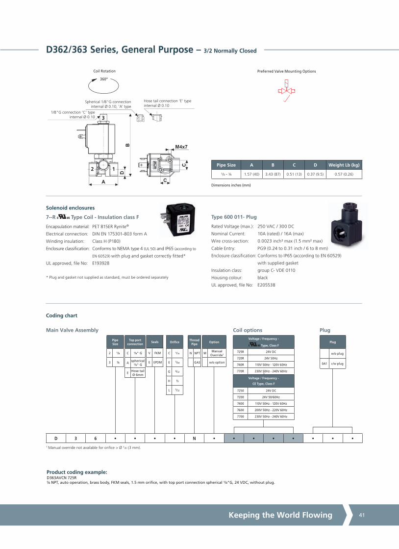
A4US
US
A4
US A4
US
A4
A4 US
US
A4
US
A4
A4 US
Keeping the World Flowing 41
Voltage / Frequency -
Type, Class F
725R 24V DC
720R 24V 50Hz
740R 110V 50Hz - 120V 60Hz
770R 230V 50Hz - 240V 60Hz
Voltage / Frequency -
CE Type, Class F
7250 24V DC
7200 24V 50/60Hz
7400 110V 50Hz - 120V 60Hz
7600 200V 50Hz - 220V 60Hz
7700 230V 50Hz - 240V 60Hz
Thread Pipe
N NPT
GAS
Top port connection
C ¹/8" G
Aspherical
¹/8" G
EHose tail Ø 6mm
Option
MManual
Override1
w/o option
Seals
V FKM
E EPDM
Pipe Size A B C D Weight Lb (kg)
¹/8 - ¼ 1.57 (40) 3.43 (87) 0.51 (13) 0.37 (9.5) 0.57 (0.26)
Dimensions inches (mm)
360º
Coil Rotation Preferred Valve Mounting Options
Pipe Size
2 ¹/8
3 1/4
Plug
w/o plug
0A1 c/w plug
Coil options
Orifice
C ¹/16
E 5/64
G ³/32
H 1/2
L 5/32
Plug
Product coding example:D363AVCN 725R 1/4 NPT, auto operation, brass body, FKM seals, 1.5 mm orifice, with top port connection spherical ¹/8”G, 24 VDC, without plug.
Main Valve Assembly
D 3 6 • • • • N • • • • • • • •
Coding chart
D362/363 Series, General Purpose – 3/2 Normally Closed
1 Manual override not available for orifice > Ø ¹/8 (3 mm).
7--R Type Coil - Insulation class F
Encapsulation material: PET 815ER Rynite®
Electrical connection: DIN EN 175301-803 form A
Winding insulation: Class H (P180)
Enclosure classification: Conforms to NEMA type 4 (UL 50) and IP65 (according to
EN 60529) with plug and gasket correctly fitted*
UL approved, file No: E193928
* Plug and gasket not supplied as standard, must be ordered separately
Solenoid enclosures
Type 600 011- Plug
Rated Voltage (max.): 250 VAC / 300 DC
Nominal Current: 10A (rated) / 16A (max)
Wire cross-section: 0.0023 inch² max (1.5 mm² max)
Cable Entry: PG9 (0.24 to 0.31 inch / 6 to 8 mm)
Enclosure classification: Conforms to IP65 (according to EN 60529)
with supplied gasket
Insulation class: group C- VDE 0110
Housing colour: black
UL approved, file No: E205538
2 1
1/8"G connection ‘C’ typeinternal Ø 0.10
Hose tail connection ‘E’ typeinternal Ø 0.10
Spherical 1/8"G connectioninternal Ø 0.10, ‘A’ type
3

A4US
US
A4
US A4
US
A4
A4 US
US
A4
US
A4
A4 US
Solenoid Valves42
LC203/204/205 Series, General Purpose – 2/2 Normally Closed, latching
Features and Benefits
• Pilot operated, latching
• Special operator with reduced stroke for low power coils
• Robust construction for industrial applications
• Stainless steel AISI 430F operators with low residual magnetism
• Coils tested 100% in compliance to RoHS directive and to relevant international standards
• Choice of high quality seal materials
• Response time 50 to 500 ms
Seal Material2 and Media Temperature Range
Media
Ambient Temperature Range
Min Max
NBR 14 °F to 194 °F(-10 °C to +90 °C)
Water, oil, air 14 °F(-10 °C)
122 °F(+50 °C)
FKM 14 °F to 266 °F(-10 °C to +130 °C)
Water, oil, air 14 °F(-10 °C)
122 °F(+50 °C)
EPDM 14 °F to 248 °F(-10 °C to +120 °C)
Water, hot water 14 °F(-10 °C)
122 °F(+50 °C)
2 See corrosion reference guide and sealing solutions for material compatability.
Pipe Size
Cv(gpm)
Kv(m3/h)
OPD psi (bar) Orifice inches(mm)
Seal
MaterialValveCodeAC
Voltages DC
Voltages
¼ 1.83 1.56
-4.4 - 73(0.3 - 5)
³³/64
(13)
NBR
FKM
EPDM
LC203DBZN
LC203DVZN
LC203DEZN
³/8 3.86 3.30
NBR
FKM
EPDM
LC204DBZN
LC204DVZN
LC204DEZN
1/2 4.42 3.78
NBR
FKM
EPDM
LC205DBZN
LC205DVZN
LC205DEZN
A
P
Specifications
Function (single acting)
A
P
Flow direction overseat 1 2
Maximum Viscosity Max. 21cST (3 °E)
Body Material (Std) Brass C37700 (UNS Designation)
Flange Stainless Steel AISI 303 (1.4305 EN 10088)
Tube Stainless Steel AISI 304
Plunger Brass C37700 (UNS Designation)
Magnet Neodym-Iron-Boron
Top Stop Stainless Steel AISI 430F or equivalent
Springs Stainless Steel AISI 302
Seal Material (Std) NBR
Connection Type NPT
Shading Ring Copper
Electrical Characteristics1
Low PowerCoil Voltage DC (=)
24 V
Voltage Tolerance +10% to -5% (DC)
Duty Cycle 100% ED
Enclosure ClassificationNEMA type 4 (UL 50) and IP65 (EN 60529)
with plug and gasket correctly fitted *
Electrical Connection to industrial form B
Coil Insulation Class 155 (F) to UL429 and to EN 60730-1
Power Rating(Low Power)
DC 3 W
Coil Absorbition(20 °C)
500mA for 20Q0
250mA for 21Q0
125mA for 22Q0
Options Available
Valve Options (see coding chart)
G parallel thread (ISO 228-1)
1 These coils are not UL approved.

A4US
US
A4
US A4
US
A4
A4 US
US
A4
US
A4
A4 US
Keeping the World Flowing 43
Option
w/o option
Thread Pipe
N NPT
GAS
Voltage / Frequency -
Class F, Low Power
20Q0 6 VDC
21Q0 12 VDC
22Q0 24 VDC
LC203/204/205 Series, General Purpose – 2/2 Normally Closed, latching
Pipe Size
03 1/4
04 3/8
05 1/2
360º
Coil Rotation
Product coding example:LC205DBZN 20Q0 1/2 NPT, auto operation, brass body, NBR seals, 33/64 orifice, 6 VDC, without plug.
Preferred Valve Mounting Options
Main Valve Assembly Coil options
Plug
w/o plug
0B1 c/w plug
Seals
B NBR
V FKM
E EPDM
LC 2 • • D • Z N • • • • • • • •
Coding chart
Dimensions inches (mm)
Plug
Pipe Size A B C D Weight Lb (kg)
¼ - ³/8 - 1/2 2.64 (67) 3.54 (90) 1.80 (45.6) 0.59 (15) 0.88 (0.4)
2-Q0 Type Coil - Insulation class F
External material: PBT (reinforced fiberglass 30%)
Electrical connection: Industrial form B
Winding insulation: Class H (E180)
Enclosure classification: Conforms to NEMA type 4 (UL 50) and IP65 (according to
EN 60529) with plug and gasket correctly fitted*
* Plug and gasket not supplied as standard, must be ordered separately.
Solenoid enclosures
Type 600 001- Plug
Rated Voltage (max.): 250 VAC / 300 DC
Nominal Current: 10A (rated) / 16A (max)
Wire cross-section: 0.0023 inch² max (1.5 mm² max)
Cable Entry: PG9 (0.24 to 0.31 inch / 6 to 8 mm)
Enclosure classification: Conforms to IP65 (according to EN 60529)
with supplied gasket
Insulation class: group C- VDE 0110
Housing colour: black
UL approved, file No: E205538

A4US
US
A4
US A4
US
A4
A4 US
US
A4
US
A4
A4 US
Solenoid Valves44
RD298/299 Series, General Purpose & High Pressure – 2/2 Normally Open
Features and Benefits
• Direct Acting
• Robust construction for industrial applications
• Stainless steel AISI 430F operators with low residual magnetism
• Coils tested 100% in compliance to RoHS directive and to relevant international standards
• Choice of high quality seal materials
• Troublefree operation with coils class H
• Response time 5 to 25 ms
Specifications
Function (single acting)
A
P
Flow direction overseat 1 2
Maximum Viscosity Max. 21cST (3 °E)
Body Material (Std) Stainless Steel AISI 303 (1.4305 EN 10088)
Orifice Material Stainless Steel AISI 303 (1.4305 EN 10088)
Flange Tube Stainless Steel AISI 303 (1.4305 EN 10088)
Plunger Stainless Steel AISI 430F (1.4106 EN 10088)
Top Stop Stainless Steel AISI 430F (1.4105 EN 10088)
Springs Stainless Steel AISI 302
Seal Material (Std) Foodgrade FKM
Connection Type NPT
Shading Ring Copper
Electrical Characteristics1
Standard
Coil Voltage DC (=)24 V
Standard
Coil Voltage AC 50 Hz (~)24 V, 110 V, 200 V, 230 V
Standard
Coil Voltage AC 60 Hz (~)24 V, 120 V, 220 V, 240 V
Voltage Tolerance +10% to -15% (AC)
+10% to -5% (DC)
Duty Cycle 100% ED
Enclosure ClassificationNEMA type 4 (UL 50) and IP65 (EN 60529)
with plug and gasket correctly fitted *
Electrical Connection to EN 175301 - 803 - A (ex DIN 43650)
Coil Insulation Class 180 (H) to EN 60730-1
Power Rating(Standard)
AC 18 VA (holding)
AC 36 VA (inrush)
DC 14 W
Options Available
Seal Material3 and Media Temperature Range
Media
Ambient Temperature Range
Min Max
FKM 14 °F to 266 °F(-10 °C to +130 °C)
Water, oil, air, aggressive fluids
14 °F(-10 °C)
122 °F(+50 °C)
EPDM 14 °F to 248 °F(-10 °C to +120 °C)
Water, hot water 14 °F(-10 °C)
122 °F(+50 °C)
RUBY 14 °F to 266 °F(-10 °C to +130 °C)
Water, liquids 14 °F(-10 °C)
122 °F(+50 °C)
3 See corrosion reference guide and sealing solutions for material compatability.
Pipe Size
Cv(gpm)
Kv(m3/h)
OPD psi (bar) Orifice inches(mm)
Seal Material
Valve CodeAC
Voltages DC
Voltages
¼ 0.04 0.04 0 - 435(0 - 30)
0 - 435(0 - 30)
³/64 (1.0)FKM
EPDM
RD299DVAN
RD299DEAN
¼ 0.16 0.140 - 290(0 - 20)
0 - 290(0 - 20)
5/64 (2.0)FKM
EPDM
RD299DVEN
RD299DEEN
¼ 0.23 0.20 0 - 203(0 - 14)
0 - 203(0 - 14)
³/32 (2.5)FKM
EPDM
RD299DVGN
RD299DEGN
¼ 0.32 0.27 0 - 131(0 - 9)
0 - 131(0 - 9)
¹/8 (3.0)FKM
EPDM
RD299DVHN
RD299DEHN
¼ 0.04 0.04 0 - 1450(0 - 100)
0 - 1450(0 - 100)
³/64 (1.0) RUBY RD299DRAN2
¼ 0.05 0.04 0 - 1233(0 - 85)
0 - 1233(0 - 85)
³/64 (1.2) RUBY RD299DRBN2
¼ 0.08 0.07 0 - 797(0 - 55)
0 - 797(0 - 55)
¹/16 (1.5) RUBY RD299DRCN2
¼ 0.16 0.14 0 - 362(0 - 25)
0 - 362(0 - 25)
5/64 (2.0) RUBY RD299DREN2
¼ 0.23 0.20 0 - 276(0 - 19)
0 - 276(0 - 19)
³/32 (2.5) RUBY RD299DRGN2
¼ 0.32 0.27 0 - 145(0 - 10)
0 - 145(0 - 10)
¹/8 (3.0) RUBY RD299DRHN2
Valve Options (see coding chart)
Body threaded connection 1/8
G parallel thread (ISO 228-1)
Anticorrosion treatment recommended with aggressive fluids
Silver shading ring
2 Not 100% leak-proof when used with air/gases. Approx leak rate is 1.5ml/min at max OPD.1 These coils are not UL approved.

A4US
US
A4
US A4
US
A4
A4 US
US
A4
US
A4
A4 US
Keeping the World Flowing 45
Thread Pipe
N NPT
GAS
Option
ASilver shading
ring
FAnticorrosion
treatment2
w/o option
Seals
V FKM
E EPDM
R RUBY
Voltage / Frequency -
Class H
7251 24 VDC
7201 24 V / 50/60 Hz
7401 110 V / 50 Hz - 120 V / 60 Hz
7601 200 V / 50 Hz - 220 V / 60 Hz
7701 230 V / 50 Hz - 240 V / 60 Hz
Pipe Size A B C D Weight Lb (kg)
¹/8 - ¼ 1.77 (45) 3.15 (80) 0.49 (12.5) 0.61 (15.4) 0.79 (0.36)
Dimensions inches (mm)
360º
Coil Rotation Preferred Valve Mounting Options
RD298/299 Series, General Purpose & High Pressure – 2/2 Normally Open
Pipe Size
8 ¹/8
9 1/4
Plug
w/o plug
0A1 c/w plug
Coil options
Orifice1
A ³/64
B ³/64
C ¹/16
E 5/64
G ³/32
H ¹/8
Plug
1 See characteristics table for availability.2 Recommended with aggressive fluids.
Product coding example:
RD299DVAN 7251 1/4 NPT, auto operation, stainless steel body, FKM seals, ³/64 orifice, 24 VDC, without plug.
Main Valve Assembly
RD 2 9 • D • • N • • • • • • • •
Coding chart
Solenoid enclosures
1 2
7--1 Type Coil - Insulation class H
External material: PPS (glass fiber & mineral filled)
Electrical connection: DIN EN 175301-803 form A
Winding insulation: Class H (E180)
Enclosure classification: Conforms to NEMA type 4 (UL 50) and IP65 (according to
EN 60529) with plug and gasket correctly fitted*
* Plug and gasket not supplied as standard, must be ordered separately.
Type 600 011- Plug
Rated Voltage (max.): 250 VAC / 300 DC
Nominal Current: 10A (rated) / 16A (max)
Wire cross-section: 0.0023 inch² max (1.5 mm² max)
Cable Entry: PG9 (0.24 to 0.31 inch / 6 to 8 mm)
Enclosure classification: Conforms to IP65 (according to EN 60529)
with supplied gasket
Insulation class: group C- VDE 0110
Housing colour: black
UL approved, file No: E205538

A4US
US
A4
US A4
US
A4
A4 US
US
A4
US
A4
A4 US
Solenoid Valves46
RD262/263 Series, General Purpose – 2/2 Normally Open
Features and Benefits
• Direct Acting
• Robust construction for industrial applications
• Stainless steel AISI 430F operators with low residual magnetism
• Coils tested 100% in compliance to RoHS directive and to relevant international standards
• Choice of high quality seal materials
• Response time 5 to 25 ms
Options Available
Seal Material2 and Media Temperature Range
Media
Ambient Temperature Range
Min Max
FKM 14 °F to 266 °F(-10 °C to +130 °C)
Water, oil, air 14 °F(-10 °C)
122 °F(+50 °C)
EPDM 14 °F to 248 °F(-10 °C to +120 °C)
Water, hot water 14 °F(-10 °C)
122 °F(+50 °C)
2 See corrosion reference guide and sealing solutions for material compatability.
Pipe Size
Cv(gpm)
Kv(m3/h)
OPD psi (bar) Orifice inches(mm)
Seal Material
Valve CodeAC
Voltages DC
Voltages
¼ 0.04 0.03 0 - 435(0 - 30)
0 - 435(0 - 30)
³/64 (1.0)FKM
EPDM
RD263DVAN
RD263DEAN
¼ 0.09 0.08 0 - 348(0 - 24)
0 - 348(0 - 24)
¹/16 (1.5)FKM
EPDM
RD263DVCN
RD263DECN
¼ 0.24 0.20 0 - 232(0 - 16)
0 - 232(0 - 16)
³/32 (2.5)FKM
EPDM
RD263DVGN
RD263DEGN
¼ 0.32 0.27 0 - 145(0 - 10)
0 - 145(0 - 10)
¹/8 (3.0)FKM
EPDM
RD263DVHN
RD263DEHN
Valve Options (see coding chart)
Body threaded connection 1/8
G parallel thread (ISO 228-1)
Electroless nickel plating
For steam version with filled PTFE seal see valve model RD236DL-N
For high pressure version with RUBY seals see valve model RD236DR-N1
Specifications
Function (single acting)
A
P
Flow direction overseat 1 2
Maximum Viscosity Max. 21cST (3 °E)
Body Material (Std) Brass (CW617N EN 12165)
Orifice Material Stainless Steel AISI 303 (1.4305 EN 10088)
Flange Tube Stainless Steel AISI 303 (1.4305 EN 10088)
Plunger Stainless Steel AISI 430F (1.4106 EN 10088)
Top Stop Stainless Steel AISI 430F (1.4105 EN 10088)
Springs Stainless Steel AISI 302
Seal Material (Std) Foodgrade FKM
Connection Type NPT
Shading Ring Copper
Electrical Characteristics1
StandardCoil Voltage DC (=)
24 V
StandardCoil Voltage AC 50 Hz (~)
24 V, 110 V, 200 V, 230 V
StandardCoil Voltage AC 60 Hz (~)
24 V, 120 V, 220 V, 240 V
Voltage Tolerance +10% to -15% (AC)
+10% to -5% (DC)
Duty Cycle 100% ED
Enclosure ClassificationNEMA type 4 (UL 50) and IP65 (EN 60529)
with plug and gasket correctly fitted *
Electrical Connection to EN 175301 - 803 - A (ex DIN 43650)
Coil Insulation Class 180 (H) to EN 60730-1
Power Rating(Standard)
AC 18 VA (holding)
AC 36 VA (inrush)
DC 14 W
1 These coils are not UL approved.

A4US
US
A4
US A4
US
A4
A4 US
US
A4
US
A4
A4 US
Keeping the World Flowing 47
Voltage / Frequency -
Class H
7251 24 VDC
7201 24 V / 50/60 Hz
7401 110 V / 50 Hz - 120 V / 60 Hz
7601 200 V / 50 Hz - 220 V / 60 Hz
7701 230 V / 50 Hz - 240 V / 60 Hz
Thread Pipe
N NPT
GAS
RD262/263 Series, General Purpose – 2/2 Normally Open
Option
KElectroless
nickel plating
w/o option
Seals
V FKM
E EPDM
Pipe Size A B C D Weight Lb (kg)
¹/8 - ¼ 1.57 (40) 3.06 (77.7) 0.73 (18.5) 0.37 (9.5) 0.57 (0.26)
Dimensions inches (mm)
360º
Coil Rotation Preferred Valve Mounting Options
Pipe Size
2 ¹/8
3 1/4
Plug
w/o plug
0A1 c/w plug
Coil options
Orifice
A ³/64
C ¹/16
G ³/32
H ¹/8
Plug
Product coding example:RD263DVHN 7251 0A1 1/4 NPT, auto operation, brass body, FKM seals, ¹/8 orifice, 24 VDC, with plug.
Main Valve Assembly
RD 2 6 • D • • N • • • • • • • •
Coding chart
Solenoid enclosures
2 1
Type 600 011- Plug
Rated Voltage (max.): 250 VAC / 300 DC
Nominal Current: 10A (rated) / 16A (max)
Wire cross-section: 0.0023 inch² max (1.5 mm² max)
Cable Entry: PG9 (0.24 to 0.31 inch / 6 to 8 mm)
Enclosure classification: Conforms to IP65 (according to EN 60529)
with supplied gasket
Insulation class: group C- VDE 0110
Housing colour: black
UL approved, file No: E205538
7--1 Type Coil - Insulation class H
External material: PPS (glass fiber & mineral filled)
Electrical connection: DIN EN 175301-803 form A
Winding insulation: Class H (E180)
Enclosure classification: Conforms to NEMA type 4 (UL 50) and IP65 (according to
EN 60529) with plug and gasket correctly fitted*
* Plug and gasket not supplied as standard, must be ordered separately.

A4US
US
A4
US A4
US
A4
A4 US
US
A4
US
A4
A4 US
Solenoid Valves48
RD236 Series, General Purpose – 2/2 Normally Open
Specifications
Function (single acting)
A
P
Flow direction 1 2
Maximum Viscosity Max. 21cST (3 °E)
Body Material (Std) Brass C37700 (UNS Designation)
Orifice Material Stainless Steel AISI 303 (1.4305 EN 10088)
Tube Stainless Steel AISI 304
Flange Stainless Steel AISI 303 (1.4305 EN 10088)
Plunger Stainless Steel AISI 430F (1.4106 EN 10088)
Top Stop Stainless Steel AISI 430F (1.4105 EN 10088)
Springs Stainless Steel AISI 302
Seal Material (Std) Foodgrade FKM
Connection Type (Std) G parallel thread (ISO 228-1)
Shading Ring Copper
Electrical Characteristics1
StandardCoil Voltage DC (=)
24 V
StandardCoil Voltage AC 50 Hz (~)
24 V, 110 V, 200 V, 230 V
StandardCoil Voltage AC 60 Hz (~)
24 V, 120 V, 220 V, 240 V
Voltage Tolerance +10% to -15% (AC)
+10% to -5% (DC)
Duty Cycle 100% ED
Enclosure ClassificationNEMA type 4 (UL 50) and IP65 (EN 60529)
with plug and gasket correctly fitted *
Electrical Connection to EN 175301 - 803 - A (ex DIN 43650)
Coil Insulation Class 155 (F) to EN 60730-1
Power Rating(Standard)
AC 18 VA (holding)
AC 36 VA (inrush)
DC 14 W
Seal Material3 and Media Temperature Range
Media
Ambient Temperature Range
Min Max
FKM 14 °F to 266 °F(-10 °C to +130 °C)
Water, oil, air 14 °F(-10 °C)
122 °F(+50 °C)
EPDM 14 °F to 248 °F(-10 °C to +120 °C)
Water, hot water 14 °F(-10 °C)
122 °F(+50 °C)
3 See corrosion reference guide and sealing solutions for material compatability.
Features and Benefits
• Direct Acting
• Robust construction for industrial applications
• Zero pressure rated
• Stainless steel AISI 430F operators with low residual magnetism
• Choice of high quality seal materials
• Response time 5 to 25 ms
Pipe Size
Cv(gpm)
Kv(m3/h)
OPD psi (bar)2 Orifice inches(mm)
Seal Material
Valve CodeAC
Voltages DC
Voltages
¼" 0.04 0.030 - 362(0 - 25)
0 - 362(0 - 25)
³/64 (1.0)FKM
EPDM
RD236DVA
RD236DEA
¼" 0.09 0.080 - 290(0 - 20)
0 - 290(0 - 20)
¹/16 (1.5)FKM
EPDM
RD236DVC
RD236DEC
¼" 0.14 0.120 - 261(0 - 18)
0 - 261(0 - 18)
5/64 (2.0)FKM
EPDM
RD236DVE
RD236DEE
¼" 0.20 0.170 - 218(0 - 15)
0 - 218(0 - 15)
³/32 (2.5)FKM
EPDM
RD236DVG
RD236DEG
¼" 0.25 0.210 - 174(0 - 12)
0 - 174(0 - 12)
¹/8 (3.0)FKM
EPDM
RD236DVH
RD236DEH
¼" 0.39 0.330 - 73(0 - 5)
0 - 73(0 - 5)
11/64 (4.5)FKM
EPDM
RD236DVM
RD236DEM
¼" 0.60 0.510 - 29(0 - 2)
0 - 29(0 - 2)
15/64 (6.0)FKM
EPDM
RD236DVP
RD236DEP
2 The valve supplied carry a nameplate with pressure ratings marked in bar.
Options Available
1 These coils are not UL approved.

A4US
US
A4
US A4
US
A4
A4 US
US
A4
US
A4
A4 US
Keeping the World Flowing 49
Voltage / Frequency -
CE Type, Class F
7250 24 VDC
7200 24 V / 50/60 Hz
7400 110 V / 50 Hz - 120 V / 60 Hz
7600 200 V / 50 Hz - 220 V / 60 Hz
7700 230 V / 50 Hz - 240 V / 60 Hz
RD236 Series, General Purpose – 2/2 Normally Open
Preferred Valve Mounting Options
360º
Coil Rotation
Pipe Size A B C D Weight Lb (kg)
¼" G 1.85 (47) 2.58 (91) HEX 22 (22) 0.82 (20.75) 0.55 (0.25)
Dimensions inches (mm)
Solenoid enclosures
Type 600 011- Plug
Rated Voltage (max.): 250 VAC / 300 DC
Nominal Current: 10A (rated) / 16A (max)
Wire cross-section: 0.0023 inch² max (1.5 mm² max)
Cable Entry: PG9 (0.24 to 0.31 inch / 6 to 8 mm)
Enclosure classification: Conforms to IP65 (according to EN 60529)
with supplied gasket
Insulation class: group C- VDE 0110
Housing colour: black
UL approved, file No: E205538
Option
w/o option
Seals
V FKM
E EPDM
Plug
0A1 c/w plug
w/o plug
Coil options
Orifice
A ³/64
C ¹/16
E 5/64
G ³/32
H ¹/8
M 11/64
P 15/64
Plug
Product coding example:
RD236DVC 7200 0A1 1/4" G, auto operation, brass body, FKM seals, ¹/16 orifice, 24 V / 50 Hz AC, with plug.
Main Valve Assembly
RD 2 3 6 D • • • • • • • • • • •
Coding chart
2 fixing holes M4x7
1 2
7--0 Type Coil - Insulation class F
External material: PBT (reinforced glass fiber 30%)
Electrical connection: DIN EN 175301-803 form A
Winding insulation: Class H (E180)
Enclosure classification: Conforms to NEMA type 4 (UL 50) and IP65 (according to
EN 60529) with plug and gasket correctly fitted*
* Plug and gasket not supplied as standard, must be ordered separately.

A4US
US
A4
US A4
US
A4
A4 US
US
A4
US
A4
A4 US
Solenoid Valves50
RB203/204/205/206/222 Series, General Purpose – 2/2 Normally Open
Features and Benefits
• Pilot operated
• Robust construction for industrial applications
• Stainless steel AISI 430F operators with low residual magnetism
• Choice of high quality seal materials
• Response time 50 to 500 ms
Options Available
Seal Material2 and Media Temperature Range
Media
Ambient Temperature Range
Min Max
NBR 14 °F to 194 °F(-10 °C to +90 °C)
Water, oil, air 14 °F(-10 °C)
122 °F(+50 °C)
FKM 14 °F to 266 °F(-10 °C to +130 °C)
Water, oil, air 14 °F(-10 °C)
122 °F(+50 °C)
EPDM 14 °F to 248 °F(-10 °C to +120 °C)
Water, hot water 14 °F(-10 °C)
122 °F(+50 °C)
2 See corrosion reference guide and sealing solutions for material compatability.
Pipe Size
Cv(gpm)
Kv(m3/h)
OPD psi (bar) Orifice inches(mm)
Seal
MaterialValve CodeAC
Voltages DC
Voltages
¼ 1.83 1.56
4 - 232(0.3 - 16)
4 - 232(0.3 - 16)
33/64
(13)
NBR
FKM
EPDM
RB203DBZN
RB203DVZN
RB203DEZN
³/8 3.86 3.30
NBR
FKM
EPDM
RB204DBZN
RB204DVZN
RB204DEZN
1/2 4.42 3.78
NBR
FKM
EPDM
RB205DBZN
RB205DVZN
RB205DEZN
3/4 compact
7.02 6.0053/64
(21)
NBR
FKM
EPDM
RB206DBXN
RB206DVXN
RB206DEXN
3/4 9.83 8.4063/64
(25)
FNBR
FKM
EPDM
RB206DBYN
RB206DVYN
RB206DEYN
1 11.23 9.60
NBR
FKM
EPDM
RB222DBYN
RB222DVYN
RB222DEYN
Valve Options (see coding chart)
G parallel thread (ISO 228-1)
Electroless nickel plating treatment
Speed control screw
CE coils, power DC 7W - AC 10 VA
Specifications
Function (single acting)
A
P
Flow direction overseat 1 2
Maximum Viscosity Max. 21cST (3 °E)
Body Material (Std) Brass C37700 (UNS Designation)
Flange Tube1 Brass C37700 (UNS Designation)
Plunger and Top Stop Stainless Steel AISI 430F or equivalent
Springs Stainless Steel AISI 302
Seal Material (Std) NBR
Connection Type NPT
Shading Ring Copper
Electrical Characteristics
Coil Voltage DC (=)24 V
Coil Voltage AC 50 Hz (~)24 V, 110 V, 230 V
Coil Voltage AC 60 Hz (~)120 V, 240 V
Voltage Tolerance +10% to -15% (AC)
+10% to -5% (DC)
Duty Cycle 100% ED
Enclosure ClassificationNEMA type 4 (UL 50) and IP65 (EN 60529)
with plug and gasket correctly fitted *
Electrical Connection to industrial form B
Coil Insulation Class 155 (F) to UL429 and to EN 60730-1
Power Rating
( Coils)
AC 9 VA (holding)AC 14 VA (inrush)
DC 6W
1 With special brass nut for NO operator (different from Standard).

A4US
US
A4
US A4
US
A4
A4 US
US
A4
US
A4
A4 US
Keeping the World Flowing 51
Voltage / Frequency -
Type, Class F
225R 24 VDC
220R 24 V / 50 Hz
240R 110 V / 50 Hz - 120 V / 60 Hz
270R 230 V / 50 Hz - 240 V / 60 Hz
Voltage / Frequency -
CE Type, Class F
2250 24 VDC
2200 24 V / 50/60 Hz
2400 110 V / 50 Hz - 120 V / 60 Hz
2600 200 V / 50 Hz - 220 V / 60 Hz
2700 230 V / 50 Hz - 240 V / 60 Hz
Option
KElectroless
nickelplating
VSpeed control
screw2
w/o option
Thread Pipe
N NPT
GAS
Pipe Size
03 1/4
04 ³/8
05 1/2
063/4
(compact)
06 3/4
22 1
360º
Coil Rotation
Product coding example:RB203DBZN 225R 1/4 NPT, auto operation, brass body, NBR seals, 33/64 orifice, 24 VDC, without plug.
Preferred Valve Mounting Options
Main Valve Assembly Coil options
Plug
w/o plug
0B1 c/w plug
Orifice1
Z 33/64
X 53/64
Y 63/64
Seals
B NBR
V FKM
E EPDM
RB 2 • • D • • N • • • • • • • •
Coding chart
Dimensions inches (mm)
Plug
Pipe size A B C D Weight Lb (kg)
¼ - ³/8 - 1/2 2.64 (67) 3.64 (92.5) 1.80 (45.6) 0.59 (15) 0.88 (0.4)
3/4 compact 3.23 (82) 4.23 (107.5) 2.03 (51.6) 0.80 (20.25) 1.32 (0.6)
3/4 to 1 3.78 (96) 4.63 (117.5) 2.83 (72) 0.91 (23) 2.65 (1.2)
Solenoid enclosures
RB203/204/205/206/222 Series, General Purpose – 2/2 Normally Open
1 DN 33/64 only for RB203/204/205, DN 53/64 only for RB206 compact, DN 63/64 only for RB206 and RB222.2 Speed control screw available on RB206D-YN and RB222D-YN.
Type 600 001- Plug
Rated Voltage (max.): 250 VaC / 300 DC
Nominal Current: 10A (rated) / 16A (max)
Wire cross-section: 0.0023 inch² max (1.5 mm² max)
Cable Entry: PG9 (0.24 to 0.31 inch / 6 to 8 mm)
Enclosure classification: Conforms to IP65 (according to EN 60529)
with supplied gasket
Insulation class: group C- VDE 0110
Housing colour: black
UL approved, file No: E205538
2--R Type Coil - Insulation class F
External material: PET 815ER Rynite®
Electrical connection: Industrial form B
Winding insulation: Class H (P180)
Enclosure classification: Conforms to NEMA type 4 (UL 50) and IP65 (according to
EN 60529) with plug and gasket correctly fitted*
UL approved, file No: E193928
* Plug and gasket not supplied as standard, must be ordered separately

A4US
US
A4
US A4
US
A4
A4 US
US
A4
US
A4
A4 US
Solenoid Valves52
ACDN Series – 2/2 Normally Open
Features and Benefits
• Robust Valve Design
• Diaphragm Operation
• Fully Ported Orifices for high flow
• Choice of valve body material seals
• Sizes 3/8” - 3/4” Advantica approved to BS EN 60730 - 2 -8 for household use when used with EPDM seals
• Response time 1” 15-60 ms
• Response time 2” 60-120 ms
• Tested in accordance with BS-EN 12266-1
Specifications
Mode of Operation
Normally Open, energise to close
Out (2)
In (1)
Maximum Viscosity 115 SSU
3/8” - 1” Body Material (Std)
Brass (Std) or Stainless Steel option
11/4” - 2” Body Material (Std)
Bronze (Std)
Flange Tube Stainless Steel
Plunger and top stop Stainless Steel
Springs Stainless Steel
Seal Material Nitrile (BunaN) (Std) other options available
Connection Type NPT
Shading Ring Copper (std), Silver (stainless steel option)
Electrical Characteristics
Coil Voltage DC (=) 12 V, 24 V
Coil Voltage AC 60 Hz (~)
24 V, 120 V
Voltage Tolerance +10% or -10%
Duty Cycle 100% ED
Electrical Connection Options
1/2” NPT metal conduit hub with 18” leads (NEMA 2 equivalent protection class)
Coil Insulation Class H
Power Rating 14.5 Watts
Options Available
Port Size
Cv Kv
OPD (psi)P. Max2
psiOrifice (mm)
Weight (lbs)AC
Voltages DC
Voltages
3/8” 3.5 3.0 0-150 0-150
725
16.0 2
1/2” 4.9 4.2 0-150 0-150 16.0 2
3/4” 5.4 4.7 0-150 0-150 16.0 2
1” 8.2 7.0 0-150 0-150 20.0 4
1¼” 26.7 23 5-150 5-150 40.0 6.6
11/2” 26.7 23 5-150 5-150 40.0 6.6
2” 30.2 26 5-150 5-150 40.0 6.6
Main Valve Body Options
Stainless Steel 316 (up to and including 1")
Oxygen Cleaning (consult factory for product code)
Stainless Steel Tagging (consult factory for product code)
Solenoid Enclosure
Protection Class
EExd T6 (NEMA 6 equivalent)
See separate datasheet EExd T4
(NEMA 6 equivalent)
1 See corrosion reference guide and sealing solutions for material compatability.
2 P. Max is limited to 675 psi when valve is fitted with an Exd solenoid operator, see separate datasheet.
1. Select the required flow.
2. Note the corresponding pressure drop.
3. Based on where the two points intersect select the most appropriate model.
How to use the flow chart
Seal Material1 and Media Temp. Range
Ambient Temperature Range
Min Max
Nitrile (14 ºF to +176 ºF) 14 ºF 122 ºF
EPDM (-58 ºF to +248 ºF) 14 ºF 122 ºF
Viton (-4 ºF to +302 ºF) 14 ºF 122 ºF
Pressure Drop
(PSI)
Water Flow (L/Min)
Pres
sure
Dro
p (B
ar)
Water Flow (GPM)2.2
1
0.110 100 1000
5 10 20 40 80 160
15
10
5
3
1.5
2" v
alve
- 40
.0 m
m o
rifice
1¼"
& 1
1/2"
valv
e - 4
0.0
mm
orifi
ce
3/4"
valv
e - 1
6.0
mm
orifi
ce
1" v
alve
- 20
.0 m
m o
rifice
1/2"
valv
e - 1
6.0
mm
orifi
ce
3 /8"
valv
e - 1
6.0
mm
orifi
ce

A4US
US
A4
US A4
US
A4
A4 US
US
A4
US
A4
A4 US
Keeping the World Flowing 53
ACDN Series – 2/2 Normally Open
360º
Coil Rotation
Dimensions given in inches
Port Size A B C D
3/8” - 3/4” 23/4” 37/16" 3" 43/8"
1” 33/8” 37/16" 3" 53/8"
1¼” - 2” 53/8” 45/8" 43/4” 57/8"
Preferred Valve Mounting Options
Dimensions
S4 Type enclosure protection class IP50
External material: Pressed steel powder coated
Electrical entry: 1/2” NPT metal conduit hub with 18” leads (NEMA 2 equivalent protection class)
Winding Insulation: Class H
Solenoid enclosures
Product coding example:
56C31Z1A1-CH298: ACDN Series 3/8” NPT, Auto, Brass body, nitrile seals, 120 V / 60Hz, 1/2” NPT electrical connection, non-UL.
Main Valve Assembly Coil options
Voltage / Frequency
F1 24 VDC
F4 12 VDC
H124 V / 60 Hz
H2120 V / 60 Hz
Electrical Connection
91/2” NPT
C •• 9 8
Valve Body Conn. Size
C 3/8”
D 1/2”
E 3/4”
F 1”
G 11/4”
H 11/2”
J 2”
Model
27ACDN
(11/4 and above)
56ACDN
(3/8"-1")
Operation
1 AUTO
Conn. Type
3 NPT
Seals
A Nitrile
B EPDM
C VITON
Style
1 Standard
Body Material
1
Brass (standard on valves up to and
including 1”)
2
Bronze (standard on valves above 1”)
5
316 Stainless Steel (option available up to
and inc 1”)
• • 3 1 Z • • 1 -
Orifice (mm)
Z Default
Enclosure
CN/O
standard metal can
Approval
8Non-
UL
D
C
B
A
Coding chart

A4US
US
A4
US A4
US
A4
A4 US
US
A4
US
A4
A4 US
Solenoid Valves54
RD223/224/225 Series, General Purpose – 2/2 Normally Open
Specifications
Function (single acting)
A
P
Flow direction overseat 1 2
Maximum Viscosity Max. 21cST (3 °E)
Body Material (Std) Brass C37700 (UNS Designation)
Flange Tube Stainless Steel AISI 303 (1.4305 EN 10088)
Plunger Stainless Steel AISI 430F (1.4106 EN 10088)
Top Stop Stainless Steel AISI 430F (1.4105 EN 10088)
Springs Stainless Steel AISI 302
Seal Material (Std) NBR
Connection Type NPT
Shading Ring Copper
Electrical Characteristics1
StandardCoil Voltage DC (=)
24 V
StandardCoil Voltage AC 50 Hz (~)
24 V, 110 V, 200 V, 230 V
StandardCoil Voltage AC 60 Hz (~)
24 V, 120 V, 220 V, 240 V
Voltage Tolerance +10% to -15% (AC)
+10% to -5% (DC)
Duty Cycle 100% ED
Enclosure ClassificationNEMA type 4 (UL 50) and IP65 (EN 60529)
with plug and gasket correctly fitted *
Electrical Connection to EN 175301 - 803 - A (ex DIN 43650)
Coil Insulation Class 180 (H) to EN 60730-1
Power Rating(Standard)
AC 18 VA (holding)
AC 36 VA (inrush)
DC 14 W
Options Available
Valve Options (see coding chart)
G parallel thread (ISO 228-1)
Electroless nickel plating
Seal Material1 and Media Temperature Range
Media
Ambient Temperature Range
Min Max
NBR 14 °F to 194 °F(-10 °C to +90 °C)
Water, oil, air 14 °F(-10 °C)
122 °F(+50 °C)
FKM 14 °F to 266 °F(-10 °C to +130 °C)
Water, oil, air 14 °F(-10 °C)
122 °F(+50 °C)
EPDM 14 °F to 248 °F(-10 °C to +120 °C)
Water, hot water 14 °F(-10 °C)
122 °F(+50 °C)
1 See corrosion reference guide and sealing solutions for material compatability.
Pipe Size
Cv(gpm)
Kv(m3/h)
OPD psi (bar) Orifice inches(mm)
Seal Material
Valve CodeAC
Voltages DC
Voltages
1 ¼ 25.97 22.20
7 - 232(0.5 - 16)
7 - 232(0.5 - 16)
1 37/64
(40)
NBR
FKM
EPDM
RD223DBKN
RD223DVKN
RD223DEKN
1 1/2 28.08 24.001 37/64
(40)
NBR
FKM
EPDM
RD224DBKN
RD224DVKN
RD224DEKN
2 37.91 32.402
(50)
NBR
FKM
EPDM
RD225DBJN
RD225DVJN
RD225DEJN
Features and Benefits
• Pilot operated
• Robust construction for industrial applications
• Stainless steel AISI 430F operators with low residual magnetism
• Choice of high quality seal materials
• Troublefree operation with coils class H
• Speed control screw as standard
• Response time 50 to 500 ms
1 These coils are not UL approved.

A4US
US
A4
US A4
US
A4
A4 US
US
A4
US
A4
A4 US
Keeping the World Flowing 55
Voltage / Frequency -
Class H
7251 24 VDC
7201 24 V / 50/60 Hz
7401 110 V / 50 Hz - 120 V / 60 Hz
7601 200 V / 50 Hz - 220 V / 60 Hz
7701 230 V / 50 Hz - 240 V / 60 Hz
Thread Pipe
N NPT
GAS
360º
Coil Rotation Preferred Valve Mounting Options
RD223/224/225 Series, General Purpose – 2/2 Normally Open
Plug
w/o plug
0A1 c/w plug
Coil options Plug
Product coding example:
RD223DBKN 7251 1 1/4 NPT, auto operation, brass body, NBR seals, 40 mm orifice, 24 VDC, without plug.
Main Valve Assembly
Coding chart
Solenoid enclosures
Dimensions inches (mm)
Pipe Size
23 1 1/4
24 1 1/2
25 2
Seals
B NBR
V VKM
E EPDM
Orifice1
K1
37/64
J 2
Option
KElectroless
nickel plating
w/o option
RD 2 • • D • • N • • • • • • • •
Type 600 011- Plug
Rated Voltage (max.): 250 VAC / 300 DC
Nominal Current: 10A (rated) / 16A (max)
Wire cross-section: 0.0023 inch² max (1.5 mm² max)
Cable Entry: PG9 (0.24 to 0.31 inch / 6 to 8 mm)
Enclosure classification: Conforms to IP65 (according to EN 60529)
with supplied gasket
Insulation class: group C- VDE 0110
Housing colour: black
UL approved, file No: E205538
1 DN 1 37/64 only for RD223 and RD224 only, DN 2 only for RD225.
Pipe Size A B C D Weight Lb (kg)
1 ¼ - 1 1/2 5.51 (140) 5.51 (140) 3.78 (96) 1.24 (31.5) 6.17 (2.8)
2 6.57 (167) 6.22 (158) 4.41 (112) 1.54 (39) 8.60 (3.9)
7--1 Type Coil - Insulation class H
External material: PPS (glass fiber & mineral filled)
Electrical connection: DIN EN 175301-803 form A
Winding insulation: Class H (E180)
Enclosure classification: Conforms to NEMA type 4 (UL 50) and IP65 (according to
EN 60529) with plug and gasket correctly fitted*
* Plug and gasket not supplied as standard, must be ordered separately.

A4US
US
A4
US A4
US
A4
A4 US
US
A4
US
A4
A4 US
Solenoid Valves56
RD398/399 Series, General Purpose – 3/2 Normally Open
Specifications
Function (single acting)
A
PR
Flow direction underseat 2 1
Maximum Viscosity Max. 21cST (3 °E)
Body Material (Std) Stainless Steel AISI 303 (1.4305 EN 10088)
Orifice Material Stainless Steel AISI 303 (1.4305 EN 10088)
Flange Tube (seamless) Stainless Steel AISI 303 (1.4305 EN 10088)
Plunger Stainless Steel AISI 430F
Top Stop Stainless Steel AISI 303 (1.4305 EN 10088)
Springs Stainless Steel AISI 302
Seal Material (Std) Foodgrade FKM
Connection Type NPT
Shading Ring Copper
Electrical Characteristics1
StandardCoil Voltage DC (=)
24 V
StandardCoil Voltage AC 50 Hz (~)
24 V, 110 V, 200 V, 230 V
StandardCoil Voltage AC 60 Hz (~)
24 V, 120 V, 220 V, 240 V
Voltage Tolerance +10% to -15% (AC)
+10% to -5% (DC)
Duty Cycle 100% ED
Enclosure ClassificationNEMA type 4 (UL 50) and IP65 (EN 60529)
with plug and gasket correctly fitted *
Electrical Connection to EN 175301 - 803 - A (ex DIN 43650)
Coil Insulation Class 180 (H) to EN 60730-1
Power Rating(Standard)
AC 18 VA (holding)
AC 36 VA (inrush)
DC 14 W
Options Available
Seal Material2 and Media Temperature Range
Media
Ambient Temperature Range
Min Max
FKM 14 °F to 266 °F(-10 °C to +130 °C)
Water, oil, air,aggressive fluids
14 °F(-10 °C)
122 °F(+50 °C)
2 See corrosion reference guide and sealing solutions for material compatability.
Valve Options (see coding chart)
Body threaded connection 1/8
G parallel thread (ISO 228-1)
Anticorrosion treatment recommended with aggressive fluids
Features and Benefits
• Direct Acting
• Robust construction for industrial applications
• Zero pressure rated
• Stainless steel AISI 430F operators with low residual magnetism
• High quality seal materials
• Response time 5 to 25 ms
Pipe Size
Cv(gpm)
Kv(m3/h)
OPD psi (bar) Orifice inches(mm)
Seal Material
Valve CodeAC
Voltages DC
Voltages
¼ 0.09 0.08 0 - 218(0 - 15)
0 - 218(0 - 15)
1/16 (1.5) FKM RD399CVCN
¼ 0.15 0.13 0 - 145(0 - 10)
0 - 145(0 - 10)
5/64 (2.0) FKM RD399CVEN
¼ 0.32 0.27 0 - 58(0 - 4)
0 - 58(0 - 4)
1/8 (3.0) FKM RD399CVHN
1 These coils are not UL approved.

A4US
US
A4
US A4
US
A4
A4 US
US
A4
US
A4
A4 US
Keeping the World Flowing 57
Voltage / Frequency -
Class H
7251 24 VDC
7201 24 V / 50/60 Hz
7401 110 V / 50 Hz - 120 V / 60 Hz
7601 200 V / 50 Hz - 220 V / 60 Hz
7701 230 V / 50 Hz - 240 V / 60 Hz
Thread Pipe
N NPT
GAS
Pipe Size
8 ¹/8
9 1/4
Option
FAnticorrosion
treatment1
w/o option
RD398/399 Series, General Purpose – 3/2 Normally Open
Preferred Valve Mounting Options
360º
Coil Rotation
Pipe size A B C D Weight Lb (kg)
¹/8 - ¼ 1.77 (45) 3.43 (87) 0.49 (12.5) 0.61 (15.4) 0.77 (0.35)
Dimensions inches (mm)
Plug
0A1 c/w plug
w/o plug
Coil options
Orifice
C ¹/16
E 5/64
H ¹/8
Plug
Product coding example:
RD399CVEN 7251 1/4 NPT, auto operation, stainless steel body, FKM seals, 5/64 orifice, 24 VDC, without plug.
Main Valve Assembly
RD 3 9 • C V • N • • • • • • • •
Coding chart
Solenoid enclosures
Type 600 011- Plug
Rated Voltage (max.): 250 VAC / 300 DC
Nominal Current: 10A (rated) / 16A (max)
Wire cross-section: 0.0023 inch² max (1.5 mm² max)
Cable Entry: PG9 (0.24 to 0.31 inch / 6 to 8 mm)
Enclosure classification: Conforms to IP65 (according to EN 60529)
with supplied gasket
Insulation class: group C- VDE 0110
Housing colour: black
UL approved, file No: E205538
2 1
1 Recommended with aggressive fluids.
7--1 Type Coil - Insulation class H
External material: PPS (glass fiber & mineral filled)
Electrical connection: DIN EN 175301-803 form A
Winding insulation: Class H (E180)
Enclosure classification: Conforms to NEMA type 4 (UL 50) and IP65 (according to
EN 60529) with plug and gasket correctly fitted*
* Plug and gasket not supplied as standard, must be ordered separately.

A4US
US
A4
US A4
US
A4
A4 US
US
A4
US
A4
A4 US
Solenoid Valves58
RD362/363 Series, General Purpose – 3/2 Normally Open
Features and Benefits
• Direct Acting
• Robust construction for industrial applications
• Zero pressure rated
• Stainless steel AISI 430F operators with low residual magnetism
• High quality seal materials
• Response time 5 to 25 ms
Specifications
Function (single acting)
A
PR
Flow direction underseat 2 1
Maximum Viscosity Max. 21cST (3 °E)
Body Material (Std) Brass C37700 (UNS Designation)
Orifice Material Stainless Steel AISI 303 (1.4305 EN 10088)
Flange Tube (seamless) Stainless Steel AISI 303 (1.4305 EN 10088)
Plunger Stainless Steel AISI 430F (1.4106 EN 10088)
Top Stop Stainless Steel AISI 430F (1.4105 EN 10088)
Springs Stainless Steel AISI 302
Seal Material (Std) Foodgrade FKM
Connection Type NPT
Shading Ring Copper
Electrical Characteristics1
StandardCoil Voltage DC (=)
24 V
StandardCoil Voltage AC 50 Hz (~)
24 V, 110 V, 200 V, 230 V
StandardCoil Voltage AC 60 Hz (~)
24 V, 120 V, 220 V, 240 V
Voltage Tolerance +10% to -15% (AC)
+10% to -5% (DC)
Duty Cycle 100% ED
Enclosure ClassificationNEMA type 4 (UL 50) and IP65 (EN 60529)
with plug and gasket correctly fitted *
Electrical Connection to EN 175301 - 803 - A (ex DIN 43650)
Coil Insulation Class 180 (H) to EN 60730-11
Power Rating(Standard)
AC 18 VA (holding)
AC 36 VA (inrush)
DC 14 W
Seal Material2 and Media Temperature Range
Media
Ambient Temperature Range
Min Max
FKM 14 °F to 266 °F(-10 °C to +130 °C)
Water, oil, air 14 °F(-10 °C)
122 °F(+50 °C)
2 See corrosion reference guide and sealing solutions for material compatability.
Pipe Size
Cv(gpm)
Kv(m3/h)
OPD psi (bar) Orifice inches(mm)
Seal Material
Valve CodeAC
Voltages DC
Voltages
¼ 0.09 0.080 - 232(0 - 16)
0 - 189(0 - 13)
¹/16 (1.5) FKM RD363CVCN
¼ 0.15 0.130 - 145(0 - 10)
0 - 145(0 - 10)
5/64 (2.0) FKM RD363CVEN
¼ 0.24 0.200 - 102
(0 - 7)
0 - 102(0 - 7)
³/32 (2.5) FKM RD363CVGN
¼ 0.32 0.270 - 58(0 - 4)
0 - 58(0 - 4)
¹/8 (3.0) FKM RD363CVHN
Options Available
Valve Options (see coding chart)
Body threaded connection 1/8
G parallel thread (ISO 228-1)
1 These coils are not UL approved.

A4US
US
A4
US A4
US
A4
A4 US
US
A4
US
A4
A4 US
Keeping the World Flowing 59
Voltage / Frequency -
Class H
7251 24 VDC
7201 24 V / 50/60 Hz
7401 110 V / 50 Hz - 120 V / 60 Hz
7601 200 V / 50 Hz - 220 V / 60 Hz
7701 230 V / 50 Hz - 240 V / 60 Hz
Thread Pipe
N NPT
GAS
RD362/363 Series, General Purpose – 3/2 Normally Open
Solenoid enclosures
Type 600 011- Plug
Rated Voltage (max.): 250 VAC / 300 DC
Nominal Current: 10A (rated) / 16A (max)
Wire cross-section: 0.0023 inch² max (1.5 mm² max)
Cable Entry: PG9 (0.24 to 0.31 inch / 6 to 8 mm)
Enclosure classification: Conforms to IP65 (according to EN 60529)
with supplied gasket
Insulation class: group C- VDE 0110
Housing colour: black
UL approved, file No: E205538
Pipe Size A B C D Weight Lb (kg)
¹/8 - ¼ 1.57 (40) 3.40 (86.4) 0.51 (13) 0.37 (9.5) 0.57 (0.26)
Dimensions inches (mm)
360º
Coil Rotation Preferred Valve Mounting Options
Pipe Size
2 ¹/8
3 1/4
Option
w/o option
Plug
0A1 c/w plug
w/o plug
Coil options
Orifice
C ¹/16
E 5/64
G ³/32
H 1/8
Plug
Product coding example:
RD362CVCN 7251 ¹/8 NPT, auto operation, brass body, FKM seals, ¹/16 orifice, 24 VDC, without plug.
Main Valve Assembly
RD 3 6 • C V • • • • • • • • • •
Coding chart
2 1
3
7--1 Type Coil - Insulation class H
External material: PPS (glass fiber & mineral filled)
Electrical connection: DIN EN 175301-803 form A
Winding insulation: Class H (E180)
Enclosure classification: Conforms to NEMA type 4 (UL 50) and IP65 (according to
EN 60529) with plug and gasket correctly fitted*
* Plug and gasket not supplied as standard, must be ordered separately.

A4US
US
A4
US A4
US
A4
A4 US
US
A4
US
A4
A4 US
Solenoid Valves60
B297 Series, Automation – 2/2 Normally Closed
Features and Benefits
• Direct Acting
• Robust construction for industrial applications
• Stainless steel AISI 430F operators with low residual magnetism
• High quality seal materials
• Valve suitable for contact with food media when used with FKM seals, as per the EEC Directives and Regulations. Please consult supplier for more details
• Response time 5 to 25 ms
Seal Material2 and Media Temperature Range
Media
Ambient Temperature Range
Min Max
FKM 14 °F to 266 °F(-10 °C to +130 °C)
Water, oil, air 14 °F(-10 °C)
122 °F(+50 °C)
EPDM 14 °F to 248 °F(-10 °C to +120 °C)
Water, hot water 14 °F(-10 °C)
122 °F(+50 °C)
2 See corrosion reference guide and sealing solutions for material compatability.
Pipe Size
Cv(gpm)
Kv(m3/h)
OPD psi (bar) Orifice inches(mm)
SealMaterial
ValveCodeAC
Voltages DC
Voltages
¹/8 0.04 0.030 - 435(0 - 30)
0 - 406(0 - 28)
³/64 (1.0)FKM
EPDM
B297DVAN
B297DEAN
¹/8 0.05 0.040 - 362(0 - 25)
0 - 160(0 - 11)
³/64 (1.2)FKM
EPDM
B297DVBN
B297DEBN
¹/8 0.07 0.060 - 290(0 - 20)
0 - 94(0 - 6.5)
¹/16 (1.5)FKM
EPDM
B297DVCN
B297DECN
¹/8 0.12 0.100 - 218(0 - 15)
0 - 51(0 - 3.5)
5/64 (2.0)FKM
EPDM
B297DVEN
B297DEEN
¹/8 0.16 0.140 - 116
(0 - 8)
0 - 14.5(0 - 1)
³/32 (2.5)FKM
EPDM
B297DVGN
B297DEGN
Valve Options (see coding chart)
G parallel thread (ISO 228-1)
Manual Override
Electroless nickel plating treatment
CE coils, power DC 7W - AC 10 VA1
Specifications
Function (single acting)
A
P
Flow direction overseat 1 2
Maximum Viscosity Max. 21cST (3 °E)
Body Material (Std) Low lead content Brass C46400 (UNS Designation)
Orifice Material Stainless Steel AISI 303 (1.4305 EN 10088)
Tube Stainless Steel AISI 304
Flange Stainless Steel AISI 303 (1.4305 EN 10088)
Plunger and Top Stop Stainless Steel AISI 430F or equivalent
Springs Stainless Steel AISI 302
Seal Material (Std) Foodgrade FKM
Connection Type NPT
Shading Ring Copper
Electrical Characteristics
Coil Voltage DC (=)24 V
Coil Voltage AC 50 Hz (~)24 V, 110 V, 230 V
Coil Voltage AC 60 Hz (~)120 V, 240 V
Voltage Tolerance +10% to -15% (AC)
+10% to -5% (DC)
Duty Cycle 100% ED
Enclosure ClassificationNEMA type 4 (UL 50) and IP65 (EN 60529)
with plug and gasket correctly fitted *
Electrical Connection to industrial form B
Coil Insulation Class 155 (F) to UL429 and to EN 60730-1
Power Rating
( Coils)
AC 9 VA (holding)AC 14 VA (inrush)
DC 6W
Options Available
1 Pressure ratings of valves fitted with CE coils may be higher than with UL coils(coils specifications on page 157).

A4US
US
A4
US A4
US
A4
A4 US
US
A4
US
A4
A4 US
Keeping the World Flowing 61
Voltage / Frequency -
Type, Class F
225R 24 DC
220R 24 V / 50 Hz
240R 110 V / 50 Hz - 120 V / 60 Hz
270R 230 V / 50 Hz - 240 V / 60 Hz
Voltage / Frequency -
CE Type, Class F
2250 24 VDC
2200 24 V / 50/60 Hz
2400 110 V / 50 Hz - 120 V / 60 Hz
2600 200 V / 50 Hz - 220 V / 60 Hz
2700 230 V / 50 Hz - 240 V / 60 Hz
Thread Pipe
N NPT
GAS
360º
Coil Rotation
Product coding example:
B297DVEN 225R ¹/8 NPT, auto operation, brass body, FKM seals, 5/64 orifice, 24 VDC, without plug.
Preferred Valve Mounting Options
B297 Series, Automation – 2/2 Normally Closed
Main Valve Assembly Coil options
Plug
w/o plug
0B1 c/w plug
Option
MManual Override
KElectroless
nickelplating
w/o option
Orifice
A ³/64
B ³/64
C ¹/16
E 5/64
G ³/32
Seals
V FKM
E EPDM
B 2 9 7 D • • N • • • • • • • •
Coding chart
Dimensions inches (mm)
Plug
Pipe Size A B C D Weight Lb (kg)
¹/8 1.18 (30) 2.56 (65) 0.71 (18) 0.28 (7) 0.33 (0.15)
2 1
Type 600 001- Plug
Rated Voltage (max.): 250 VAC / 300 DC
Nominal Current: 10A (rated) / 16A (max)
Wire cross-section: 0.0023 inch² max (1.5 mm² max)
Cable Entry: PG9 (0.24 to 0.31 inch / 6 to 8 mm)
Enclosure classification: Conforms to IP65 (according to EN 60529)
with supplied gasket
Insulation class: group C- VDE 0110
Housing colour: black
UL approved, file No: E205538
2--R Type Coil - Insulation class F
External material: PET 815ER Rynite®
Electrical connection: Industrial form B
Winding insulation: Class H (P180)
Enclosure classification: Conforms to NEMA type 4 (UL 50) and IP65 (according to
EN 60529) with plug and gasket correctly fitted*
UL approved, file No: E193928
* Plug and gasket not supplied as standard, must be ordered separately.
Solenoid enclosures

A4US
US
A4
US A4
US
A4
A4 US
US
A4
US
A4
A4 US
Solenoid Valves62
D301 Series, Automation – 2/2 Normally Closed
Specifications
Function (single acting)
A
PR
Flow direction underseat 2 1
Maximum Viscosity Max. 21cST (3 °E)
Body Material (Std) Brass C37700 (UNS Designation)
Orifice Material Stainless Steel AISI 303 (1.4305 EN 10088)
Flange Stainless Steel AISI 303 (1.4305 EN 10088)
Tube Stainless Steel AISI 304
Plunger Stainless Steel AISI 430F (1.4106 EN 10088)
Top Stop Stainless Steel AISI 430F (1.4105 EN 10088)
Springs Stainless Steel AISI 302
Seal Material (Std) Foodgrade FKM
Connection Type (Std) Flanged 1.26x1.26 inches
Shading Ring Copper
Electrical Characteristics1
StandardCoil Voltage DC (=)
24 V
StandardCoil Voltage AC 50 Hz (~)
24 V, 110 V, 200 V, 230 V
StandardCoil Voltage AC 60 Hz (~)
24 V, 120 V, 220 V, 240 V
Voltage Tolerance +10% to -15% (AC)
+10% to -5% (DC)
Duty Cycle 100% ED
Enclosure ClassificationNEMA type 4 (UL 50) and IP65 (EN 60529)
with plug and gasket correctly fitted *
Electrical Connection to EN 175301 - 803 - A (ex DIN 43650)
Coil Insulation Class 155 (F) to EN 60730-1
Power Rating(Standard)
AC 18 VA (holding)
AC 36 VA (inrush)
DC 14 W
Options Available
Seal Material3 and Media Temperature Range
Media
Ambient Temperature Range
Min Max
FKM 14 °F to 266 °F(-10 °C to +130 °C)
Water, oil, air 14 °F(-10 °C)
122 °F(+50 °C)
3 See corrosion reference guide and sealing solutions for material compatability.
Pipe Size
Cv(gpm)
Kv(m3/h)
OPD psi (bar)2 Orifice inches(mm)
Seal Material
Valve CodeAC
Voltages DC
Voltages
Flanged 0.09 0.080 - 261(0 - 18)
0 - 261(0 - 18)
¹/16 (1.5) FKM D301CVC
Flanged 0.15 0.130 - 145(0 - 10)
0 - 145(0 - 10)
5/64 (2.0) FKM D301CVE
Flanged 0.24 0.200 - 102
(0 - 7)
0 - 102(0 - 7)
³/32 (2.5) FKM D301CVG
Flanged 0.32 0.270 - 73(0 - 5)
0 - 73(0 - 5)
¹/8 (3.0) FKM D301CVH
Features and Benefits
• Direct Acting
• Zero pressure rated
• Robust construction for industrial applications
• Stainless steel AISI 430F operators with low residual magnetism
• High quality seal materials
• Response time 5 to 25 ms
2 The valve supplied carry a nameplate with pressure ratings marked in bar.1 These coils are not UL approved.

A4US
US
A4
US A4
US
A4
A4 US
US
A4
US
A4
A4 US
Keeping the World Flowing 63
Voltage / Frequency -
CE Type, Class F
7250 24 VDC
7200 24 V / 50/60 Hz
7400 110 V / 50 Hz - 120 V / 60 Hz
7600 200 V / 50 Hz - 220 V / 60 Hz
7700 230 V / 50 Hz - 240 V / 60 Hz
Orifice
C ¹/16
E 5/64
G ³/32
H ¹/8
Option
w/o option
Pipe Size A B C D Weight Lb (kg)
Flanged 1.26 (32) 3.03 (77) 0.94 (24) 0.40 (10.25) 0.55 (0.25)
Dimensions inches (mm)
360º
Coil Rotation Preferred Valve Mounting Options
Top Port
CG ¹/8" conn
Aspherical
G ¹/8"
Ewith
hose tail
Plug
w/o plug
0A1 c/w plug
Coil options Plug
Product coding example:
D301CVC 7250 Flanged, auto operation, brass body, FKM seals, ¹/16 orifice, 24 VDC, without plug.
Main Valve Assembly
D 3 0 1 • V • • • • • • • • • •
Coding chart
Solenoid enclosures
D301 Series, Automation – 2/2 Normally Closed
Type 600 011- Plug
Rated Voltage (max.): 250 VAC / 300 DC
Nominal Current: 10A (rated) / 16A (max)
Wire cross-section: 0.0023 inch² max (1.5 mm² max)
Cable Entry: PG9 (0.24 to 0.31 inch / 6 to 8 mm)
Enclosure classification: Conforms to IP65 (according to EN 60529)
with supplied gasket
Insulation class: group C- VDE 0110
Housing colour: black
UL approved, file No: E205538
7--0 Type Coil - Insulation class F
External material: PBT (reinforced glass fiber 30%)
Electrical connection: DIN EN 175301-803 form A
Winding insulation: Class H (E180)
Enclosure classification: Conforms to NEMA type 4 (UL 50) and IP65 (according to
EN 60529) with plug and gasket correctly fitted*
* Plug and gasket not supplied as standard, must be ordered separately.

A4US
US
A4
US A4
US
A4
A4 US
US
A4
US
A4
A4 US
Solenoid Valves64
RB297 Series, Automation – 2/2 Normally Open
Features and Benefits
• Direct Acting
• Robust construction for industrial applications
• Stainless steel AISI 430F operators with low residual magnetism
• High quality seal materials
• Response time 5 to 25 ms
• Valve suitable for contact with food media when used with FKM seals, as per EEC Directives and Regulations. Please consult supplier for more details
Options Available
Seal Material2 and Media Temperature Range
Media
Ambient Temperature Range
Min Max
FKM 14 °F to 266 °F(-10 °C to +130 °C)
Water, oil, air 14 °F(-10 °C)
122 °F(+50 °C)
EPDM 14 °F to 248 °F(-10 °C to +120 °C)
Water, hot water 14 °F(-10 °C)
122 °F(+50 °C)
2 See corrosion reference guide and sealing solutions for material compatability.
Pipe Size
Cv(gpm)
Kv(m3/h)
OPD psi (bar) Orifice inches(mm)
SealMaterial
ValveCodeAC
Voltages DC
Voltages
¹/8 0.04 0.030 - 362(0 - 25)
0 - 362(0 - 25)
³/64 (1.0)FKM
EPDM
RB297DVAN
RB297DEAN
¹/8 0.05 0.040 - 290(0 - 20)
0 - 290(0 - 20)
³/64 (1.2)FKM
EPDM
RB297DVBN
RB297DEBN
¹/8 0.07 0.06 0 - 218(0 - 15)
0 - 218(0 - 15)
¹/16 (1.5)FKM
EPDM
RB297DVCN
RB297DECN
¹/8 0.12 0.100 - 145(0 - 10)
0 - 145(0 - 10)
5/64 (2.0)FKM
EPDM
RB297DVEN
RB297DEEN
¹/8 0.16 0.140 - 73(0 - 5)
0 - 73(0 - 5)
³/32 (2.5)FKM
EPDM
RB297DVGN
RB297DEGN
¹/8 0.21 0.180 - 65(0 - 4.5)
0 - 65(0 - 4.5)
¹/8 (3.0)FKM
EPDM
RB297DVHN
RB297DEHN
Valve Options
G parallel thread (ISO 228-1)
Electroless nickel plating treatment
Specifications
Function (single acting)
Flow direction overseat 1 2
Maximum Viscosity Max. 21cST (3 °E)
Body Material (Std) Low lead content Brass C46400 (UNS Designation)
Orifice Material Stainless Steel AISI 303 (1.4305 EN 10088)
Flange Tube1 Brass C37700 (UNS Designation)
Plinger and Top Stop Stainless Steel AISI 430F or equivalent
Springs Stainless Steel AISI 302
Seal Material (Std) Foodgrade FKM
Connection Type NPT
Shading Ring Copper
Electrical Characteristics1
StandardCoil Voltage DC (=)
24 V
StandardCoil Voltage AC 50 Hz (~)
24 V, 110 V, 200 V, 230 V
StandardCoil Voltage AC 60 Hz (~)
24 V, 120 V, 220 V, 240 V
Voltage Tolerance +10% to -15% (AC)
+10% to -5% (DC)
Duty Cycle 100% ED
Enclosure ClassificationNEMA type 4 (UL 50) and IP65 (EN 60529)
with plug and gasket correctly fitted *
Electrical Connection to industrial form B
Coil Insulation Class 155 (F) to UL429 and to EN 60730-1
Power Rating(Standard)
AC 10 VA (holding)
AC 16 VA (inrush)
DC 10 W
A
P
1 These coils are not UL approved.

A4US
US
A4
US A4
US
A4
A4 US
US
A4
US
A4
A4 US
Keeping the World Flowing 65
Voltage / Frequency -
CE Type, Class F
2250 24 VDC
2200 24 V / 50/60 Hz
2400 110 V / 50 Hz - 120 V / 60 Hz
2600 200 V / 50 Hz - 220 V / 60 Hz
2700 230 V / 50 Hz - 240 V / 60 Hz
Thread Pipe
N NPT
GAS
Dimensions inches (mm)
360º
Coil Rotation
Product coding example:
RB297DEE 2250 ¹/8" G, auto operation, brass body, EPDM seals, 5/64 orifice, 24 VDC, without plug.
Preferred Valve Mounting Options
RB297 Series, Automation – 2/2 Normally Open
Pipe Size A B C D Weight Lb (kg)
¹/8 1.18 (30) 2.66 (67.5) 0.71 (18) 0.28 (7) 0.33 (0.15)
Plug
w/o plug
0B1 c/w plug
Option
KElectroless
nickelplating
w/o option
Orifice
A ³/64
B ³/64
C ¹/16
E 5/64
G ³/32
H ¹/8
Seals
V FKM
E EPDM
RB 2 9 7 D • • N • • • • • • • •
Main Valve Assembly Coil options
Coding chart
Plug
2 1
Solenoid enclosures
Type 600 001- Plug
Rated Voltage (max.): 250 VAC / 300 DC
Nominal Current: 10A (rated) / 16A (max)
Wire cross-section: 0.0023 inch² max (1.5 mm² max)
Cable Entry: PG9 (0.24 to 0.31 inch / 6 to 8 mm)
Enclosure classification: Conforms to IP65 (according to EN 60529)
with supplied gasket
Insulation class: group C- VDE 0110
Housing colour: black
UL approved, file No: E205538
2--0 Type Coil - Insulation class F
External material: PBT (reinforced fiberglass 30%)
Electrical connection: Industrial form B
Winding insulation: Class H (E180)
Enclosure classification: Conforms to NEMA type 4 (UL 50) and IP65 (according to
EN 60529) with plug and gasket correctly fitted*
* Plug and gasket not supplied as standard, must be ordered separately.

A4US
US
A4
US A4
US
A4
A4 US
US
A4
US
A4
A4 US
Solenoid Valves66
RD301 Series, Automation – 2/2 Normally Open
Specifications
Function (single acting)
A
PR
Flow direction underseat 2 1
Maximum Viscosity Max. 21cST (3 °E)
Body Material (Std) Brass C37700 (UNS Designation)
Orifice Material Stainless Steel AISI 303 (1.4305 EN 10088)
Flange Tube Stainless Steel AISI 303 (1.4305 EN 10088)
Plunger Stainless Steel AISI 430F (1.4106 EN 10088)
Top Stop Stainless Steel AISI 430F (1.4105 EN 10088)
Springs Stainless Steel AISI 302
Seal Material Foodgrade FKM
Connection Type (Std) Flanged 1.26x1.26 inches
Shading Ring Copper
Electrical Characteristics1
StandardCoil Voltage DC (=)
24 V
StandardCoil Voltage AC 50 Hz (~)
24 V, 110 V, 200 V, 230 V
StandardCoil Voltage AC 60 Hz (~)
24 V, 120 V, 220 V, 240 V
Voltage Tolerance +10% to -15% (AC)
+10% to -5% (DC)
Duty Cycle 100% ED
Enclosure ClassificationNEMA type 4 (UL 50) and IP65 (EN 60529)
with plug and gasket correctly fitted *
Electrical Connection to EN 175301 - 803 - A (ex DIN 43650)
Coil Insulation Class 180 (H) to EN 60730-1
Power Rating(Standard)
AC 18 VA (holding)
AC 36 VA (inrush)
DC 14 W
Seal Material3 and Media Temperature Range
Media
Ambient Temperature Range
Min Max
FKM 14 °F to 266 °F(-10 °C to +130 °C)
Water, oil, air 14 °F(-10 °C)
122 °F(+50 °C)
3 See corrosion reference guide and sealing solutions for material compatability.
Pipe Size
Cv(gpm)
Kv(m3/h)
OPD psi (bar)2 Orifice inches(mm)
Seal Material
Valve CodeAC
Voltages DC
Voltages
Flanged 0.09 0.080 - 218(0 - 15)
0 - 218(0 - 15)
¹/16 (1.5) FKM RD301CVC
Flanged 0.15 0.130 - 145(0 - 10
0 - 145(0 - 10)
5/64 (2.0) FKM RD301CVE
Flanged 0.32 0.270 - 58(0 - 4)
0 - 58(0 - 4)
¹/8 (3.0) FKM RD301CVH
Features and Benefits
• Direct Acting
• Zero pressure rated
• Robust construction for industrial applications
• Stainless steel AISI 430F operators with low residual magnetism
• High quality seal materials
• Response time 5 to 25 ms
2 The valve supplied carry a nameplate with pressure ratings marked in bar.
Options Available
1 These coils are not UL approved.

A4US
US
A4
US A4
US
A4
A4 US
US
A4
US
A4
A4 US
Keeping the World Flowing 67
Voltage / Frequency -
Class H
7251 24 VDC
7201 24 V / 50/60 Hz
7401 110 V / 50 Hz - 120 V / 60 Hz
7601 200 V / 50 Hz - 220 V / 60 Hz
7701 230 V / 50 Hz - 240 V / 60 Hz
Option
w/o option
Pipe Size A B C D Weight Lb (kg)
Flanged 1.26 (32) 3.06 (77.7) 0.94 (24) 0.40 (10.25) 0.55 (0.25)
Dimensions inches (mm)
360º
Coil Rotation Preferred Valve Mounting Options
Plug
w/o plug
0A1 c/w plug
Coil options Plug
Product coding example:
RD301CVC 7251 Flanged, auto operation, brass body, FKM seals, ¹/16 orifice, 24 VDC, without plug.
Main Valve Assembly
Coding chart
Orifice
C ¹/16
E 5/64
H ¹/8
RD301 Series, Automation – 2/2 Normally Open
RD 3 0 1 C V • • • • • • • • • •
Solenoid enclosures
Type 600 011- Plug
Rated Voltage (max.): 250 VAC / 300 DC
Nominal Current: 10A (rated) / 16A (max)
Wire cross-section: 0.0023 inch² max (1.5 mm² max)
Cable Entry: PG9 (0.24 to 0.31 inch / 6 to 8 mm)
Enclosure classification: Conforms to IP65 (according to EN 60529)
with supplied gasket
Insulation class: group C- VDE 0110
Housing colour: black
UL approved, file No: E205538
7--1 Type Coil - Insulation class H
External material: PPS (glass fiber & mineral filled)
Electrical connection: DIN EN 175301-803 form A
Winding insulation: Class H (E180)
Enclosure classification: Conforms to NEMA type 4 (UL 50) and IP65 (according to
EN 60529) with plug and gasket correctly fitted*
* Plug and gasket not supplied as standard, must be ordered separately.

A4US
US
A4
US A4
US
A4
A4 US
US
A4
US
A4
A4 US
Solenoid Valves68
SB397 Series, Automation – 2nd Service 3/2 Normally Open
Specifications
Function (single acting)
A
P R
Flow direction OFF 3 1 - ON 1 2
Maximum Viscosity Max. 21cST (3 °E)
Body Material (Std) Low lead content Brass C46400 (UNS Designation)
Orifice Material Stainless Steel AISI 303 (1.4305 EN 10088)
Tube Stainless Steel AISI 304
Flange Stainless Steel AISI 303 (1.4305 EN 10088)
Plunger Stainless Steel AISI 430F or equivalent
Top Stop Stainless Steel AISI 430F (1.4105 EN 10088)
Springs Stainless Steel AISI 302
Seal Material (Std) Foodgrade FKM
Connection Type NPT
Shading Ring Copper
Electrical Characteristics1
StandardCoil Voltage DC (=)
24 V
StandardCoil Voltage AC 50 Hz (~)
24 V, 110 V, 200 V, 230 V
StandardCoil Voltage AC 60 Hz (~)
24 V, 120 V, 220 V, 240 V
Voltage Tolerance +10% to -15% (AC)
+10% to -5% (DC)
Duty Cycle 100% ED
Enclosure ClassificationNEMA type 4 (UL 50) and IP65 (EN 60529)
with plug and gasket correctly fitted *
Electrical Connection to industrial form B
Coil Insulation Class 155 (F) to UL429 and to EN 60730-1
Power Rating(Standard)
AC 10V A (holding)
AC 16 VA (inrush)
DC 10 W
Options Available
Seal Material2 and Media Temperature Range
Media
Ambient Temperature Range
Min Max
FKM 14 °F to 266 °F(-10 °C to +130 °C)
Water, oil, air 14 °F(-10 °C)
122 °F(+50 °C)
2 See corrosion reference guide and sealing solutions for material compatability.
Valve Options (see coding chart)
G parallel thread (ISO 228-1)
Manual Override
Electroless nickel plating treatment
Features and Benefits
• Direct Acting
• Robust construction for industrial applications
• Zero pressure rated
• Stainless steel AISI 430F operators with low residual magnetism
• High quality seal materials
• Valve suitable for contact with food media when used with FKM seals, as per the EEC Directives and Regulations. Please consult supplier for more details
• Response time 5 to 25 ms
Pipe Size
Cv(gpm)
Kv(m3/h)
OPD psi (bar) Orifice inches (mm)12 13
Seal Material
Valve CodeAC
Voltages DC
Voltages
¹/8 0.05 0.040 - 87(0 - 6)
0 - 44(0 - 3)
³/64
(1.2)¹/16 (1.7)
FKM SB397CVBN
¹/8 0.07 0.060 -65
(0 - 4.5)
0 - 29(0 - 2)
¹/16 (1.5)
¹/16 (1.7)
FKM SB397CVCN
1 These coils are not UL approved.

A4US
US
A4
US A4
US
A4
A4 US
US
A4
US
A4
A4 US
Keeping the World Flowing 69
Voltage / Frequency -
CE Type, Class F
2250 24 VDC
2200 24 V / 50/60 Hz
2400 110 V / 50 Hz - 120 V / 60 Hz
2600 200 V / 50 Hz - 220 V / 60 Hz
2700 230 V / 50 Hz - 240 V / 60 Hz
Thread Pipe
N NPT
GAS
Orifice
B ³/64
C ¹/16
SB397 Series, Automation – 2nd Service 3/2 Normally Open
Preferred Valve Mounting Options
360º
Coil Rotation
Pipe Size A B C D Weight Lb (kg)
¹/8 1.18 (30) 2.67 (67.8) 0.71 (18) 0.28 (7) 0.33 (0.15)
Dimensions inches (mm)
Solenoid enclosures
Type 600 001- Plug
Rated Voltage (max.): 250 VAC / 300 DC
Nominal Current: 10A (rated) / 16A (max)
Wire cross-section: 0.0023 inch² max (1.5 mm² max)
Cable Entry: PG9 (0.24 to 0.31 inch / 6 to 8 mm)
Enclosure classification: Conforms to IP65 (according to EN 60529)
with supplied gasket
Insulation class: group C- VDE 0110
Housing colour: black
UL approved, file No: E205538
Option
MManual
Override
KElectroless
nickel plating
w/o option
Plug
0B1 c/w plug
w/o plug
Coil options Plug
Product coding example:
SB397CVBN 2250 ¹/8 NPT, auto operation, brass body, FKM seals, ³/64 orifice, with manual override, 24 VDC, without plug.
Main Valve Assembly
SB 3 9 7 C V • N • • • • • • • •
Coding chart
1/8”G connection ‘C’ typeinternal Ø 0.07
2--0 Type Coil - Insulation class F
External material: PBT (reinforced fiberglass 30%)
Electrical connection: Industrial form B
Winding insulation: Class H (E180)
Enclosure classification: Conforms to NEMA type 4 (UL 50) and IP65 (according to
EN 60529) with plug and gasket correctly fitted*
* Plug and gasket not supplied as standard, must be ordered separately.

A4US
US
A4
US A4
US
A4
A4 US
US
A4
US
A4
A4 US
Solenoid Valves70
RB397 Series, Automation – 3/2 Normally Open
Specifications
Function (single acting)
A
PR
Flow direction underseat 2 1
Maximum Viscosity Max. 21cST (3 °E)
Body Material (Std) Low lead content Brass C46400 (UNS Designation)
Orifice Material Stainless Steel AISI 303 (1.4305 EN 10088)
Tube Stainless Steel AISI 304
Flange Stainless Steel AISI 303 (1.4305 EN 10088)
Plunger Stainless Steel AISI 430F or equivalent
Top Stop Stainless Steel AISI 430F (1.4105 EN 10088)
Springs Stainless Steel AISI 302
Seal Material (Std) Foodgrade FKM
Connection Type NPT
Shading Ring Copper
Electrical Characteristics1
StandardCoil Voltage DC (=)
24 V
StandardCoil Voltage AC 50 Hz (~)
24 V, 110 V, 200 V, 230 V
StandardCoil Voltage AC 60 Hz (~)
24 V, 120 V, 220 V, 240 V
Voltage Tolerance +10% to -15% (AC)
+10% to -5% (DC)
Duty Cycle 100% ED
Enclosure ClassificationNEMA type 4 (UL 50) and IP65 (EN 60529)
with plug and gasket correctly fitted *
Electrical Connection to industrial form B
Coil Insulation Class 155 (F) to UL429 and to EN 60730-1
Power Rating(Standard)
AC 10 VA (holding)
AC 16 VA (inrush)
DC 10 W
Options Available
Seal Material2 and Media Temperature Range
Media
Ambient Temperature Range
Min Max
FKM 14 °F to 266 °F(-10 °C to +130 °C)
Water, oil, air 14 °F(-10 °C)
122 °F(+50 °C)
EPDM 14 °F to 248 °F(-10 °C to +120 °C)
Water, hot water 14 °F(-10 °C)
122 °F(+50 °C)
2 See corrosion reference guide and sealing solutions for material compatability.
Valve Options (see coding chart)
G parallel thread (ISO 228-1)
Electroless nickel plating treatment
Features and Benefits
• Direct Acting
• Robust construction for industrial applications
• Zero pressure rated
• Stainless steel AISI 430F operators with low residual magnetism
• Choice of high quality seal materials
• Valve suitable for contact with food media when used with FKM seals, as per the EEC Directives and Regulations. Please consult supplier for more details
• Response time 5 to 25 ms
Pipe Size
Cv(gpm)
Kv(m3/h)
OPD psi (bar) Orifice inches(mm)
Seal Material
Valve CodeAC
Voltages DC
Voltages
¹/8 0.04 0.03 0 - 218(0 - 15)
0 - 174(0 - 12)
³/64 (1.0)FKM
EPDM
RB397CVAN
RB397CEAN
¹/8 0.05 0.04 0 - 218(0 - 15)
0 - 174(0 - 12)
³/64 (1.2)FKM
EPDM
RB397CVBN
RB397CEBN
¹/8 0.07 0.06 0 - 145(0 - 10)
0 - 116(0 - 8)
¹/16 (1.5)FKM
EPDM
RB397CVCN
RB397CECN
¹/8 0.13 0.11 0 - 116(0 - 8)
0 - 87(0 - 6)
5/64 (2.0)FKM
EPDM
RB397CVEN
RB397CEEN
¹/8 0.18 0.15 0 - 58(0 - 4)
0 - 58(0 - 4)
³/32 (2.5)FKM
EPDM
RB397CVGN
RB397CEGN
¹/8 0.25 0.21 0 - 51(0 - 3.5)
0 - 51(0 - 3.5)
¹/8 (3.0)FKM
EPDM
RB397CVHN
RB397CEHN1 These coils are not UL approved.

A4US
US
A4
US A4
US
A4
A4 US
US
A4
US
A4
A4 US
Keeping the World Flowing 71
Voltage / Frequency -
CE Type, Class F
2250 24 VDC
2200 24 /V 50/60 Hz
2400 110 V / 50 Hz - 120 V / 60 Hz
2600 200 V / 50 Hz - 220 V / 60 Hz
2700 230 V / 50 Hz - 240 V / 60 Hz
Orifice
A ³/64
B ³/64
C ¹/16
E 5/64
G ³/32
H ¹/8
Thread Pipe
N NPT
GAS
RB397 Series, Automation – 3/2 Normally Open
Preferred Valve Mounting Options
360º
Coil Rotation
Pipe Size A B C D Weight Lb (kg)
¹/8 1.18 (30) 2.99 (75.9) 0.71 (18) 0.28 (7) 0.33 (0.15)
Dimensions inches (mm)
Solenoid enclosures
Type 600 001- Plug
Rated Voltage (max.): 250 VAC / 300 DC
Nominal Current: 10A (rated) / 16A (max)
Wire cross-section: 0.0023 inch² max (1.5 mm² max)
Cable Entry: PG9 (0.24 to 0.31 inch / 6 to 8 mm)
Enclosure classification: Conforms to IP65 (according to EN 60529)
with supplied gasket
Insulation class: group C- VDE 0110
Housing colour: black
UL approved, file No: E205538
Option
KElectroless
nickel plating
w/o option
Seals
V FKM
E EPDM
Plug
0B1 c/w plug
w/o plug
Coil options Plug
Product coding example:
RB397CVBN 2400 ¹/8 NPT, auto operation, brass body, FKM seals, 1.2 mm orifice, 110 V / 50 Hz - 120 V / 60 Hz, without plug.
Main Valve Assembly
RB 3 9 7 C • • N • • • • • • • •
Coding chart
1/8" G connection ‘C’ typeinternal Ø 0.07
2--0 Type Coil - Insulation class F
External material: PBT (reinforced fiberglass 30%)
Electrical connection: Industrial form B
Winding insulation: Class H (E180)
Enclosure classification: Conforms to NEMA type 4 (UL 50) and IP65 (according to
EN 60529) with plug and gasket correctly fitted*
* Plug and gasket not supplied as standard, must be ordered separately.

A4US
US
A4
US A4
US
A4
A4 US
US
A4
US
A4
A4 US
Solenoid Valves72
GD362/363 Series, Automation – Universal Service 3/2 (Normally Open)
Features and Benefits
• Direct Acting
• Robust construction for industrial applications
• Zero pressure rated
• Stainless steel AISI 430F operators with low residual magnetism
• High quality seal materials
• Response time 5 to 25 ms
Specifications
Function (single acting)
A
PR
Pressure can be connected to any port
Maximum Viscosity Max. 21cST (3 °E)
Body Material (Std) Brass C37700 (UNS Designation)
Orifice Material Stainless Steel AISI 303 (1.4305 EN 10088)
Flange Stainless Steel AISI 303 (1.4305 EN 10088)
Tube Stainless Steel AISI 304
Plunger Stainless Steel AISI 430F (1.4106 EN 10088)
Top Stop Stainless Steel AISI 430F (1.4105 EN 10088)
Springs Stainless Steel AISI 302
Seal Material (Std) Foodgrade FKM
Connection Type NPT
Shading Ring Copper
Electrical Characteristics
StandardCoil Voltage DC (=)
24 V
StandardCoil Voltage AC 50 Hz (~)
24 V, 110 V, 200 V, 230 V
StandardCoil Voltage AC 60 Hz (~)
24 V, 120 V, 220 V, 240 V
Voltage Tolerance +10% to -15% (AC)
+10% to -5% (DC)
Duty Cycle 100% ED
Enclosure classificationNEMA type 4 (UL 50) and IP65 (EN 60529)
with plug and gasket correctly fitted *
Electrical Connection to EN 175301 - 803 - A (ex DIN 43650)
Coil Insulation Class 155 (F) to EN 60730-1
Power Rating(Standard)
AC 18 VA (holding)
AC 36 VA (inrush)
DC 14 W
Seal Material1 and Media Temperature Range
Media
Ambient Temperature Range
Min Max
FKM 14 °F to 266 °F(-10 °C to +130 °C)
Water, oil, air 14 °F(-10 °C)
122 °F(+50 °C)
1 See corrosion reference guide and sealing solutions for material compatability.
Pipe Size
Cv(gpm)
Kv(m3/h)
OPD psi (bar) Orifice inches (mm) 12 13
Seal Material
Valve CodeAC
Voltages DC
Voltages
¼ 0.15 0.13 0 - 116(0 - 8)
0 - 102(0 - 7)
5/64 (2.0)
5/64 (2.0)
FKM GD363CVEN
Options Available
Valve Options (see coding chart)
Body threaded connection 1/8
G parallel thread (ISO 228-1)
1 These coils are not UL approved.

A4US
US
A4
US A4
US
A4
A4 US
US
A4
US
A4
A4 US
Keeping the World Flowing 73
Voltage / Frequency -
CE Type, Class F
7250 24 VDC
7200 24 V / 50/60 Hz
7400 110 V / 50 Hz - 120 V / 60 Hz
7600 200 V / 50 Hz - 220 V / 60 Hz
7700 230 V / 50 Hz - 240 V / 60 Hz
Plug
0A1 c/w plug
w/o plug
Thread Pipe
N NPT
GAS
Top port connection
C ¹/8” G
Aspherical
¹/8” G
GD362/363 Series, Automation – Universal Service 3/2 (Normally Open)
Solenoid enclosures
Type 600 011- Plug
Rated Voltage (max.): 250 VAC / 300 DC
Nominal Current: 10A (rated) / 16A (max)
Wire cross-section: 0.0023 inch² max (1.5 mm² max)
Cable Entry: PG9 (0.24 to 0.31 inch / 6 to 8 mm)
Enclosure classification: Conforms to IP65 (according to EN 60529)
with supplied gasket
Insulation class: group C- VDE 0110
Housing colour: black
UL approved, file No: E205538
Pipe Size A B C D Weight Lb (kg)
¹/8 - ¼ 1.57 (40) 3.43 (87) 0.51 (13) 0.37 (9.5) 0.57 (0.26)
Dimensions inches (mm)
360º
Coil Rotation Preferred Valve Mounting Options
Pipe Size
2 ¹/8
3 1/4
Option
w/o option
Coil options Plug
Product coding example:
SD363CVEN 7250 1/4 NPT, auto operation, universal, brass body, FKM seals, 5/64 orifice, with top port connection ¹/8”G, 24 VDC, without plug.
Main Valve Assembly
GD 3 6 • • V E N • • • • • • • •
Coding chart
2 1
3
1/8" G connection ‘C’ type internal Ø 0.08
Spherical 1/8" G connection 'A' type internal Ø 0.08
7--0 Type Coil - Insulation class F
External material: PBT (reinforced glass fiber 30%)
Electrical connection: DIN EN 175301-803 form A
Winding insulation: Class H (E180)
Enclosure classification: Conforms to NEMA type 4 (UL 50) and IP65 (according to
EN 60529) with plug and gasket correctly fitted*
* Plug and gasket not supplied as standard, must be ordered separately.

A4US
US
A4
US A4
US
A4
A4 US
US
A4
US
A4
A4 US
Solenoid Valves74
SD362/363 Series, Automation – 2nd service 3/2 (Normally Open)
Features and Benefits
• Direct Acting
• Robust construction for industrial applications
• Zero pressure rated
• Stainless steel AISI 430F operators with low residual magnetism
• High quality seal materials
• Response time 5 to 25 ms
Specifications
Function (single acting)
A
P R
Flow direction OFF 3 1 - ON 1 2
Maximum Viscosity Max. 21cST (3 °E)
Body Material (Std) Brass C37700 (UNS Designation)
Orifice Material Stainless Steel AISI 303 (1.4305 EN 10088)
Flange Stainless Steel AISI 303 (1.4305 EN 10088)
Tube Stainless Steel AISI 304
Plunger Stainless Steel AISI 430F (1.4106 EN 10088)
Top Stop Stainless Steel AISI 430F (1.4105 EN 10088)
Springs Stainless Steel AISI 302
Seal Material (Std) Foodgrade FKM
Connection Type NPT
Shading Ring Copper
Electrical Characteristics1
StandardCoil Voltage DC (=)
24 V
StandardCoil Voltage AC 50 Hz (~)
24 V, 110 V, 200 V, 230 V
StandardCoil Voltage AC 60 Hz (~)
24 V, 120 V, 220 V, 240 V
Voltage Tolerance +10% to -15% (AC)
+10% to -5% (DC)
Duty Cycle 100% ED
Enclosure ClassificationNEMA type 4 (UL 50) and IP65 (EN 60529)
with plug and gasket correctly fitted *
Electrical Connection to EN 175301 - 803 - A (ex DIN 43650)
Coil Insulation Class 155 (F) to EN 60730-1
Power Rating(Standard)
AC 18 VA (holding)
AC 36 VA (inrush)
DC 14 W
Seal Material2 and Media Temperature Range
Media
Ambient Temperature Range
Min Max
FKM 14 °F to 266 °F(-10 °C to +130 °C)
Water, oil, air 14 °F(-10 °C)
122 °F(+50 °C)
2 See corrosion reference guide and sealing solutions for material compatability.
Pipe Size
Cv(gpm)
Kv(m3/h)
OPD psi (bar) Orifice inches (mm) 12 13
Seal Material
Valve CodeAC
Voltages DC
Voltages
¼ 0.09 0.080 - 218(0 - 15)
0 - 218(0 - 15)
¹/16
(1.5)¹/16
(1.5)FKM SD363CVCN
¼ 0.15 0.130 - 218(0 - 15)
0 - 218(0 - 15)
5/64
(2.0)
5/64
(2.0)FKM SD363CVEN
¼ 0.24 0.200 - 189(0 - 13)
0 - 189(0 - 13)
³/32
(2.5)³/32
(2.5)FKM SD363CVGN
Options Available
Valve Options (see coding chart)
Body threaded connection 1/8
G parallel thread (ISO 228-1)
Manual Override
1 These coils are not UL approved.

A4US
US
A4
US A4
US
A4
A4 US
US
A4
US
A4
A4 US
Keeping the World Flowing 75
Voltage / Frequency -
CE Type, Class F
7250 24 VDC
7200 24 V / 50/60 Hz
7400 110 V / 50 Hz - 120 V / 60 Hz
7600 200 V / 50 Hz - 220 V / 60 Hz
7700 230 V / 50 Hz - 240 V / 60 Hz
Thread Pipe
N NPT
GAS
Top port connection
C ¹/8" G
Aspherical
¹/8" G
SD362/363 Series, Automation – 2nd service 3/2 (Normally Open)
Solenoid enclosures
Type 600 011- Plug
Rated Voltage (max.): 250 VAC / 300 DC
Nominal Current: 10A (rated) / 16A (max)
Wire cross-section: 0.0023 inch² max (1.5 mm² max)
Cable Entry: PG9 (0.24 to 0.31 inch / 6 to 8 mm)
Enclosure classification: Conforms to IP65 (according to EN 60529)
with supplied gasket
Insulation class: group C- VDE 0110
Housing colour: black
UL approved, file No: E205538
Pipe size A B C D Weight Lb (kg)
¹/8 - ¼ 1.57 (40) 3.43 (87) 0.51 (13) 0.37 (9.5) 0.57 (0.26)
Dimensions inches (mm)
360º
Coil Rotation Preferred Valve Mounting Options
Pipe Size
2 ¹/8
3 1/4
Option
MManual
Override
w/o option
Plug
0A1 c/w plug
w/o plug
Coil options
Orifice
C ¹/16
E 5/64
G ³/32
Plug
Product coding example:
SD362AVGN 7400 ¹/8 NPT, auto operation, 2nd service, brass body, FKM seals, ³/32 orifice, with top port connection spherical ¹/8"G, 110 V / 50 Hz - 120 V / 60 Hz, without plug.
Main Valve Assembly
SD 3 6 • • V • N • • • • • • • •
Coding chart
2 1
3
1/8" G connection ‘C’ type internal Ø 0.08 or Ø 0.10
Spherical 1/8" G connection 'A' type internal Ø 0.08 or Ø 0.10
7--0 Type Coil - Insulation class F
External material: PBT (reinforced glass fiber 30%)
Electrical connection: DIN EN 175301-803 form A
Winding insulation: Class H (E180)
Enclosure classification: Conforms to NEMA type 4 (UL 50) and IP65 (according to
EN 60529) with plug and gasket correctly fitted*
* Plug and gasket not supplied as standard, must be ordered separately.

A4US
US
A4
US A4
US
A4
A4 US
US
A4
US
A4
A4 US
Solenoid Valves76
DD362/363 Series, Automation – Diverting 3/2 (Normally Open)
Features and Benefits
• Direct Acting
• Robust construction for industrial applications
• Zero pressure rated
• Stainless steel AISI 430F operators with low residual magnetism
• High quality seal materials
• Response time 5 to 25 ms
Specifications
Function (single acting)A
P
R
Flow direction OFF 1 3 - ON 1 2
Maximum Viscosity Max. 21cST (3 °E)
Body Material (Std) Brass C37700 (UNS Designation)
Orifice Material Stainless Steel AISI 303 (1.4305 EN 10088)
Flange Stainless Steel AISI 303 (1.4305 EN 10088)
Tube Stainless Steel AISI 304
Plunger Stainless Steel AISI 430F (1.4106 EN 10088)
Top Stop Stainless Steel AISI 430F (1.4105 EN 10088)
Springs Stainless Steel AISI 302
Seal Material (Std) Foodgrade FKM
Connection Type NPT
Shading Ring Copper
Electrical Characteristics1
StandardCoil Voltage DC (=)
24 V
StandardCoil Voltage AC 50 Hz (~)
24 V, 110 V, 200 V, 230 V
StandardCoil Voltage AC 60 Hz (~)
24 V, 120 V, 220 V, 240 V
Voltage Tolerance +10% to -15% (AC)
+10% to -5% (DC)
Duty Cycle 100% ED
Enclosure ClassificationNEMA type 4 (UL 50) and IP65 (EN 60529)
with plug and gasket correctly fitted *
Electrical Connection to EN 175301 - 803 - A (ex DIN 43650)
Coil Insulation Class 155 (F) to EN 60730-1
Power Rating(Standard)
AC 18 VA (holding)
AC 36 VA (inrush)
DC 14 W
Seal Material2 and Media Temperature Range
Media
Ambient Temperature Range
Min Max
FKM 14 °F to 266 °F(-10 °C to +130 °C)
Water, oil, air 14 °F(-10 °C)
122 °F(+50 °C)
2 See corrosion reference guide and sealing solutions for material compatability.
Pipe Size
Cv(gpm)
Kv(m3/h)
OPD psi (bar) Orifice inches (mm) 12 13
Seal Material
Valve CodeAC
Voltages DC
Voltages
¼" 0.09 0.080 - 290(0 - 20)
0 - 290 (0 - 20)
¹/16 (1.5)
³/32 (2.5)
FKM DD363CVCN
¼" 0.15 0.130 - 290 (0 - 20)
0 - 290(0 - 20)
5/64 (2.0)
³/32 (2.5)
FKM DD363CVEN
Options Available
Valve Options (see coding chart)
Body threaded connection 1/8" NPT
G parallel thread (ISO 228-1)
Manual Override
1 These coils are not UL approved.

A4US
US
A4
US A4
US
A4
A4 US
US
A4
US
A4
A4 US
Keeping the World Flowing 77
Voltage / Frequency -
CE Type, Class F
7250 24 VDC
7200 24 V / 50/60 Hz
7400 110 V / 50 Hz - 120 V / 60 Hz
7600 200 V / 50 Hz - 220 V / 60 Hz
7700 230 V / 50 Hz - 240 V / 60 Hz
Thread Pipe
N NPT
GAS
2 1
31/8"G connection ‘C’ type
internal Ø 0.10
DD362/363 Series, Automation – Diverting 3/2 (Normally Open)
Solenoid enclosures
Type 600 011- Plug
Rated Voltage (max.): 250 VAC / 300 DC
Nominal Current: 10A (rated) / 16A (max)
Wire cross-section: 0.0023 inch² max (1.5 mm² max)
Cable Entry: PG9 (0.24 to 0.31 inch / 6 to 8 mm)
Enclosure classification: Conforms to IP65 (according to EN 60529)
with supplied gasket
Insulation class: group C- VDE 0110
Housing colour: black
UL approved, file No: E205538
Pipe Size A B C D Weight Lb (kg)
¹/8 - ¼ 1.57 (40) 3.43 (87) 0.51 (13) 0.37 (9.5) 0.57 (0.26)
Dimensions inches (mm)
360º
Coil Rotation Preferred Valve Mounting Options
Pipe Size
2 ¹/8
3 1/4
Option
MManual
Override
w/o option
Plug
0A1 c/w plug
w/o plug
Coil options
Orifice
C ¹/16
E 5/64
Plug
Product coding example:
DD362CVEN 7250 ¹/8 NPT, auto operation, diverting, brass body, FKM seals, 5/64 orifice, 24 VDC, without plug.
Main Valve Assembly
DD 3 6 • C V • N • • • • • • • •
Coding chart
7--0 Type Coil - Insulation class F
External material: PBT (reinforced glass fiber 30%)
Electrical connection: DIN EN 175301-803 form A
Winding insulation: Class H (E180)
Enclosure classification: Conforms to NEMA type 4 (UL 50) and IP65 (according to
EN 60529) with plug and gasket correctly fitted*
* Plug and gasket not supplied as standard, must be ordered separately.

A4US
US
A4
US A4
US
A4
A4 US
US
A4
US
A4
A4 US
Solenoid Valves78
D298/299 Series, High Pressure – 2/2 Normally Closed
Features and Benefits
• Direct Acting
• Robust construction for industrial applications
• Stainless steel AISI 430F operators with low residual magnetism
• Coils tested 100% in compliance to RoHS directive and to relevant international standards
• High quality seal materials
• Wide range of available orifices
• Response time 5 to 25 ms
Specifications
Function (single acting)
A
P
Flow direction overseat 1 2
Maximum Viscosity Max. 21cST (3 °E)
Body Material (Std) Stainless Steel AISI 303 (1.4305 EN 10088)
Orifice Material Stainless Steel AISI 303 (1.4305 EN 10088)
Flange Tube (seamless) Stainless Steel AISI 303 (1.4305 EN 10088)
Plunger Stainless Steel AISI 430F (1.4106 EN 10088)
Top Stop Stainless Steel AISI 430F (1.4105 EN 10088)
Springs Stainless Steel AISI 302
Seal Material (Std) Ruby
Connection Type NPT
Shading Ring Copper
Electrical Characteristics1
High PowerCoil Voltage DC (=)
24 V
High PowerCoil Voltage AC 50 Hz (~)
24 V, 110 V, 230 V
High PowerCoil Voltage AC 60 Hz (~)
24 V, 120 V, 240 V
Voltage Tolerance +10% to -15% (AC)
+10% to -5% (DC)
Duty Cycle 100% ED
Enclosure ClassificationNEMA type 4 (UL 50) and IP65 (EN 60529)
with plug and gasket correctly fitted *
Electrical Connection to EN 175301 - 803 - A (ex DIN 43650)
Coil Insulation Class 180 (H) to EN 60730-1
Power Rating(High Power)
AC 25 VA (holding)
AC 50 VA (inrush)
DC 22 Watts
Seal Material4 and Media Temperature Range
Media
Ambient Temperature Range
Min Max
RUBY 14 °F to 266 °F(-10 °C to +130 °C)
Water, oil, air, aggressive fluids
14 °F(-10 °C)
122 °F(+50 °C)
4 See corrosion reference guide and sealing solutions for material compatability.
Valve Options (see coding chart)
Body threaded connection 1/8
G parallel thread (ISO 228-1)
Anticorrosion treatment recommended with aggressive fluids
Silver shading ring
Pipe Size
Cv2
(gpm)Kv2
(m3/h)
OPD psi (bar)3Orifice inches(mm)
Seal Material
Valve CodeAC
Voltages DC
Voltages
¼ 0.05 0.040 - 2900(0 - 200)
0 - 1595(0 - 110)
³/64 (1.2) RUBY D299DRBN1
¼ 0.08 0.070 - 2900(0 - 200)
0 - 1160(0 - 80)
¹/16 (1.5) RUBY D299DRCN1
¼ 0.16 0.14 0 - 2030(0 - 140)
0 - 435(0 - 30)
5/64 (2.0) RUBY D299DREN1
¼ 0.23 0.20 0 - 1305(0 - 90)
0 - 333(0 - 23)
³/32 (2.5) RUBY D299DRGN1
¼ 0.32 0.27 0 - 725(0 - 50)
0 - 203(0 - 14)
1/8 (3.0) RUBY D299DRHN1
3 When high pressure valves are supplied without a coil, their nameplates display the max OPD of the valve when equipped with an AC (25VA) and DC (22W) coil. If fitting coils with a different power rating OPD will vary, please consult supplier for more details.
2 Not 100% leak-proof when used with air/gases. Approx leak rate is 1.5ml/min at max OPD.
Options Available
1 High power coils are not UL approved.

A4US
US
A4
US A4
US
A4
A4 US
US
A4
US
A4
A4 US
Keeping the World Flowing 79
Thread Pipe
N NPT
GAS
Orifice
B 3/64
C ¹/16
E 5/64
G ³/32
H ¹/8
Pipe Size
8 ¹/8
9 1/4
Plug
w/o plug
0A1 c/w plug
Voltage / Frequency -
Class H, High Power
72Z1 24 VDC
72K1 24 V / 50/60 Hz
74K1 110 V / 50 Hz - 120 V / 60 Hz
77K1 230 V / 50 Hz - 240 V / 60 Hz
Pipe Size A B C D Weight Lb (kg)
¹/8 - ¼ 1.77 (45) 3.15 (80) 0.49 (12.5) 0.61 (15.4) 0.79 (0.36)
Dimensions inches (mm)
360º
Coil Rotation
Main Valve Assembly Coil options
D 2 9 • D R • N 1 • • • • • • •
Product coding example:D298DRCN1 72Z1 0A1 ¹/8 NPT, auto operation, stainless steel body, RUBY seals, ¹/16 orifice, 24 VDC, with plug.
Plug
Preferred Valve Mounting Options
D298/299 Series, High Pressure – 2/2 Normally Closed
Solenoid enclosures
Coding chart
Contact supplier for options.
1 2
7-K1 & 7-Z1 Type Coil - Insulation class H
External material: PPS (glass fiber & mineral filled)
Electrical connection: DIN EN 175301-803 form A
Winding insulation: Class H (E180)
Enclosure classification: Conforms to NEMA type 4 (UL 50) and IP65 (according to
EN 60529) with plug and gasket correctly fitted*
* Plug and gasket not supplied as standard, must be ordered separately.
Type 600 011- Plug
Rated Voltage (max.): 250 VAC / 300 DC
Nominal Current: 10A (rated) / 16A (max)
Wire cross-section: 0.0023 inch² max (1.5 mm² max)
Cable Entry: PG9 (0.24 to 0.31 inch / 6 to 8 mm)
Enclosure classification: Conforms to IP65 (according to EN 60529)
with supplied gasket
Insulation class: group C- VDE 0110
Housing colour: black
UL approved, file No: E205538

A4US
US
A4
US A4
US
A4
A4 US
US
A4
US
A4
A4 US
Solenoid Valves80
D262/263 Series, High Pressure – 2/2 Normally Closed
Features and Benefits
• Direct Acting
• Robust construction for industrial applications
• Stainless steel AISI 430F operators with low residual magnetism
• Coils tested 100% in compliance to RoHS directive and to relevant international standards
• High quality seal materials
• Response time 5 to 25 ms
Specifications
Function (single acting)
A
P
Flow direction overseat 1 2
Maximum Viscosity max. 21cST (3 °E)
Body Material (Std) Brass C37700 (UNS Designation)
Orifice Material Stainless Steel AISI 303 (1.4305 EN 10088)
Flange Tube (seamless) Stainless Steel AISI 303 (1.4305 EN 10088)
Plunger Stainless Steel AISI 430F (1.4106 EN 10088)
Top Stop Stainless Steel AISI 430F (1.4105 EN 10088)
Springs Stainless Steel AISI 302
Seal Material (Std) RUBY
Connection Type NPT
Shading Ring Copper
Electrical Characteristics1
High Power
Coil Voltage DC (=)24 V
High Power
Coil Voltage AC 50 Hz (~)24 V, 110 V, 230 V
High Power
Coil Voltage AC 60 Hz (~)24 V, 120 V, 240 V
Voltage Tolerance +10% to -15% (AC)
+10% to -5% (DC)
Duty Cycle 100% ED
Enclosure ClassificationNEMA type 4 (UL 50) and IP65 (EN 60529)
with plug and gasket correctly fitted *
Electrical Connection to EN 175301 - 803 - A (ex DIN 43650)
Coil Insulation Class 180 (H) to EN 60730-1
Power Rating(High Power)
AC 25 VA (holding)
AC 50 VA (inrush)
DC 22W
Options Available
Seal Material4 and Media Temperature Range
Media
Ambient Temperature Range
Min Max
RUBY 14 °F to 266 °F(-10 °C to +130 °C)
Water, oil, air, aggressive fluids
14 °F(-10 °C)
122 °F(+50 °C)
4 See corrosion reference guide and sealing solutions for material compatability.
Pipe Size
Cv2
(gpm)Kv2
(m3/h)
OPD psi (bar)3Orifice inches(mm)
Seal Material
Valve CodeAC
Voltages DC
Voltages
¼ 0.05 0.04 0 - 2900(0 - 200)
0 - 870(0 - 60)
³/64 (1.2) RUBY D263DRBN1
¼ 0.09 0.08 0 - 2900(0 - 200)
0 -507(0 - 35)
¹/16 (1.5) RUBY D263DRCN1
¼ 0.15 0.13 0 - 1740(0 - 120)
0 - 362(0 - 25)
5/64 (2.0) RUBY D263DREN1
¼ 0.32 0.27 0 - 725(0 - 50)
0 - 160(0 - 11)
¹/8 (3.0) RUBY D263DRHN1
Valve Options (see coding chart)
Body threaded connection 1/8
G parallel thread (ISO 228-1)
3 When high pressure valves are supplied without a coil, their nameplates display the max OPD of the valve when equipped with an AC (25VA) and DC(22W) coil. If fitting coils with a different power rating OPD will vary, please consult supplier for more details.
2 Not 100% leak-proof when used with air/gases. Approx leak rate is 1.5ml/min at max OPD.1 High power coils are not UL approved.

A4US
US
A4
US A4
US
A4
A4 US
US
A4
US
A4
A4 US
Keeping the World Flowing 81
Thread Pipe
N NPT
GAS
Voltage / Frequency -
Class H, High Power
72Z1 24 VDC
72K1 24 V / 50/60 Hz
74K1 110 V / 50 Hz - 120 V / 60 Hz
77K1 230 V / 50 Hz - 240 V / 60 Hz
D262/263 Series, High Pressure – 2/2 Normally Closed
Pipe Size A B C D Weight Lb (kg)
¹/8 - ¼ 1.57 (40) 3.05 (77.5) 0.73 (18.5) 0.37 (9.5) 0.57 (0.26)
Dimensions inches (mm)
360º
Coil Rotation Preferred Valve Mounting Options
Pipe Size
2 ¹/8
3 1/4
Plug
w/o plug
0A1 c/w plug
Coil options
Orifice
B ³/64
C ¹/16
E 5/64
H ¹/8
Plug
Product coding example:D263DRBN1 72Z1 0A1 1/4 NPT, auto operation, brass body, RUBY seals, 3/64 orifice, 24 VDC, with plug.
Main Valve Assembly
Coding chart
Solenoid enclosures
D 2 6 • D R • N 1 • • • • • • •
2 1
7-K1 & 7-Z1 Type Coil - Insulation class H
External material: PPS (glass fiber & mineral filled)
Electrical connection: DIN EN 175301-803 form A
Winding insulation: Class H (E180)
Enclosure classification: Conforms to NEMA type 4 (UL 50) and IP65 (according to
EN 60529) with plug and gasket correctly fitted*
* Plug and gasket not supplied as standard, must be ordered separately.
Type 600 011- Plug
Rated Voltage (max.): 250 VAC / 300 DC
Nominal Current: 10A (rated) / 16A (max)
Wire cross-section: 0.0023 inch² max (1.5 mm² max)
Cable Entry: PG9 (0.24 to 0.31 inch / 6 to 8 mm)
Enclosure classification: Conforms to IP65 (according to EN 60529)
with supplied gasket
Insulation class: group C- VDE 0110
Housing colour: black
UL approved, file No: E205538
Contact supplier for options.

A4US
US
A4
US A4
US
A4
A4 US
US
A4
US
A4
A4 US
Solenoid Valves82
D634/635/636 Series, High Pressure – 2/2 Normally Closed
Features and Benefits
• Pilot operated
• Robust construction for industrial applications
• Stainless steel AISI 430F operators with low residual magnetism
• Coils tested 100% in compliance to RoHS directive and to relevant international standards
• High quality seal materials
• Response time 5 to 25 ms
Pipe Size
Cv2
(gpm)Kv2
(m3/h)
OPD psi (bar)3Orifice inches(mm)
Seal Material
Valve CodeAC
Voltages DC
Voltages
¼ 1.47 1.264.4 - 2030(0.3 - 140)
4.4 - 507 (0.3 - 35)
25/64 (10) PTFE D634DTTN1
³/8 1.68 1.444.4 - 2030(0.3 - 140)
4.4 - 507 (0.3 - 35)
25/64 (10) PTFE D635DTTN1
1/2 1.76 1.504.4 - 2030(0.3 - 140)
4.4 - 507 (0.3 - 35)
25/64 (10) PTFE D636DTTN1
Specifications
Function (single acting)
A
P
Flow direction overseat 1 2
Maximum Viscosity Max. 21cST (3 °E)
Body Material (Std) Brass C37700 (UNS Designation)
Orifice Material Stainless Steel AISI 303 (1.4305 EN 10088)
Flange Tube (seamless) Stainless Steel AISI 303 (1.4305 EN 10088)
Plunger Stainless Steel AISI 430F (1.4106 EN 10088)
Top Stop Stainless Steel AISI 430F (1.4105 EN 10088)
Piston Material Brass C37700 (UNS Designation)
Springs Stainless Steel AISI 302
Seal Material (Std) PTFE
Connection Type NPT
Shading Ring Copper
Electrical Characteristics1
High Power
Coil Voltage DC (=)24 V
High PowerCoil Voltage AC 50 Hz (~)
24 V, 110 V, 200 V, 230 V
High PowerCoil Voltage AC 60 Hz (~)
24 V, 120 V, 220 V, 240 V
Voltage Tolerance +10% to -15% (AC)
+10% to -5% (DC)
Duty Cycle 100% ED
Enclosure ClassificationNEMA type 4 (UL 50) and IP65 (EN 60529)
with plug and gasket correctly fitted *
Electrical Connection to EN 175301 - 803 - A (ex DIN 43650)
Coil Insulation Class 180 (H) to EN 60730-1
Power Rating(High Power)
AC 25 VA (holding)
AC 50 VA (inrush)
DC 22 W
Seal Material4 and Media Temperature Range
Media
Ambient Temperature Range
Min Max
PTFE 14 °F to 266 °F(-10 °C to +130 °C)
Water, oil, liquids 14 °F(-10 °C)
122 °F(+50 °C)
4 See corrosion reference guide and sealing solutions for material compatability.
2 Not 100% leak-proof when used with air/gases. Approx leak rate is 1.5ml/min at max OPD.3 When high pressure valves are supplied without a coil, their nameplates display the max OPD
of the valve when equipped with an AC (25VA) and DC (22W) coil. If fitting coils with a different power rating OPD will vary, please consult supplier for more details.
Options Available
Valve Options (see coding chart)
G parallel thread (ISO 228-1)
1 High power coils are not UL approved.

A4US
US
A4
US A4
US
A4
A4 US
US
A4
US
A4
A4 US
Keeping the World Flowing 83
Thread Pipe
N NPT
GAS
Pipe Size A B C D Weight Lb (kg)
¼" 2.13 (54) 3.94 (100) HEX 27 (27) 0.59 (15) 1.10 (0.5)
³/8" to 1/2" 2.13 (54) 3.94 (100) HEX 27 (27) 0.59 (15) 0.99 (0.45)
Dimensions inches (mm)
360º
Coil Rotation Preferred Valve Mounting Options
Pipe Size
4 1/4
5 ³/8
6 1/2
Plug
w/o plug
0A1 c/w plug
Coil options Plug
Product coding example:D634DTTN1 72Z1 1/4 NPT, auto operation, brass body, PTFE seals, 25/64 orifice, 24 VDC, without plug.
Main Valve Assembly
Coding chart
D634/635/636 Series, High Pressure – 2/2 Normally Closed
Voltage / Frequency -
Class H, High Power
72Z1 24 VDC
72K1 24 V / 50/60 Hz
74K1 110 V / 50 Hz - 120 V / 60 Hz
77K1 230 V / 50 Hz - 240 V / 60 Hz
D 6 3 • D T T N 1 • • • • • • •
Solenoid enclosures
7-K1 & 7-Z1 Type Coil - Insulation class H
External material: PPS (glass fiber & mineral filled)
Electrical connection: DIN EN 175301-803 form A
Winding insulation: Class H (E180)
Enclosure classification: Conforms to NEMA type 4 (UL 50) and IP65 (according to
EN 60529) with plug and gasket correctly fitted*
* Plug and gasket not supplied as standard, must be ordered separately.
Type 600 011- Plug
Rated Voltage (max.): 250 VAC / 300 DC
Nominal Current: 10A (rated) / 16A (max)
Wire cross-section: 0.0023 inch² max (1.5 mm² max)
Cable Entry: PG9 (0.24 to 0.31 inch / 6 to 8 mm)
Enclosure classification: Conforms to IP65 (according to EN 60529)
with supplied gasket
Insulation class: group C- VDE 0110
Housing colour: black
UL approved, file No: E205538

A4US
US
A4
US A4
US
A4
A4 US
US
A4
US
A4
A4 US
Solenoid Valves84
Features and Benefits
• Pilot operated
• Robust construction for industrial applications
• Stainless steel AISI 430F operators with low
residual magnetism
• High quality seal materials
• Response time 50 to 500 ms
Specifications
Function (single acting)
A
P
Flow direction overseat 1 2
Maximum Viscosity Max. 21cST (3 °E)
Body Material (Std) Brass C37700 (UNS Designation)
Orifice Material Stainless Steel AISI 303 (1.4305 EN 10088)
Flange Tube (seamless) Stainless Steel AISI 303 (1.4305 EN 10088)
Plunger Stainless Steel AISI 430F (1.4106 EN 10088)
Top Stop Stainless Steel AISI 430F (1.4105 EN 10088)
Springs Stainless Steel AISI 302
Operator Seal Material1 RUBY
Diaphragm Material FKM
Main Seal Material1 PTFE
Connection Type NPT
Shading Ring Copper
Electrical Characteristics
Coil Voltage DC (=)24 V
Coil Voltage AC 50 Hz (~)24 V, 110 V, 230 V
Coil Voltage AC 60 Hz (~)120 V, 240 V
Voltage Tolerance +10% to -15% (AC)
+10% to -5% (DC)
Duty Cycle 100% ED
Enclosure ClassificationNEMA type 4 (UL 50) and IP65 (EN 60529)
with plug and gasket correctly fitted *
Electrical Connection to EN 175301 - 803 - A (ex DIN 43650)
Coil Insulation Class 155 (F) to UL429 and to EN 60730-1
Power Rating
( Coils)
AC 15 VA (holding)
AC 30 VA (inrush)
DC 10 W
Options Available
Valve Options (see coding chart)
G parallel thread (ISO 228-1)
CE coils, power DC 14W - AC 18 VA
Seal Material3 and Media Temperature Range
Media
Ambient Temperature Range
Min Max
PTFE 14 °F to 266 °F(-10 °C to +130 °C)
Water4, oil, air 14 °F(-10 °C)
122 °F(+50 °C)
FKM 14 °F to 266 °F(-10 °C to +130 °C)
Water4, oil, air 14 °F(-10 °C)
122 °F(+50 °C)
3 See corrosion reference guide and sealing solutions for material compatability.4 When using liquid fluids waterhammer and pressures higher than 290 psi (20 barg) can cause
the diaphragm to tear.
D232/233/234 Series, High Pressure & Compressed Air – 2/2 Normally Closed
Pipe Size
Cv(gpm)
Kv(m3/h)
OPD psi (bar) Orifice inches(mm)
SealMaterial
ValveCodeAC
Voltages DC
Voltages
³/8 2.95 2.5214.5 - 725
(1 - 50)
14.5 - 725(1 - 50)
21/32 (16) PTFE D232DTWN2
1/2 3.23 2.7614.5 - 725
(1 - 50)
14.5 - 725(1 - 50)
21/32 (16) PTFE D233DTWN2
3/4 3.37 2.8814.5 - 725
(1 - 50)
14.5 - 725(1 - 50)
21/32 (16) PTFE D234DTWN2
³/8 2.95 2.521.5 - 362
(1 - 25)
1.5 - 362(1 - 25)
21/32 (16) FKM D232DVWN
1/2 3.23 2.761.5 - 362
(1 - 25)
1.5 - 362(1 - 25)
21/32 (16) FKM D233DVWN
3/4 3.37 2.881.5 - 362
(1 - 25)
1.5 - 362(1 - 25)
21/32 (16) FKM D234DVWN
1 For D23-DVWN operator seal material is foodgrade FKM and main sealmaterial is FKM.
2 Not 100% leak-proof when used with air/gases. Approximate leak rate is 1,5 ml/min at max. OPD.

A4US
US
A4
US A4
US
A4
A4 US
US
A4
US
A4
A4 US
Keeping the World Flowing 85
Voltage / Frequency -
Type, Class F
725R 24 VDC
720R 24 V / 50 Hz
740R 110 V / 50 Hz - 120 V / 60 Hz
770R 230 V / 50 Hz - 240 V / 60 Hz
Voltage / Frequency -
CE Type, Class F
7250 24 VDC
7200 24 V / 50/60 Hz
7400 110 V / 50 Hz - 120 V / 60 Hz
7600 200 V / 50 Hz - 220 V / 60 Hz
7700 230 V / 50 Hz - 240 V / 60 Hz
Option
w/o option
Thread Pipe
N NPT
GAS
Seals
T PTFE
V FKM
Pipe Size
2 ³/8
3 1/2
4 3/4
Pipe Size A B C D Weight Lb (kg)
³/8 3.39 (86) 4.59 (116.5) 1.98 (50.2) 0.69 (17.5) 2.20 (1)
1/2 - 3/4 3.39 (86) 4.59 (116.5) 1.98 (50.2) 0.69 (17.5) 1.98 (0.9)
Dimensions inches (mm)
360º
Coil Rotation Preferred Valve Mounting Options
Plug
w/o plug
0A1 c/w plug
Coil options Plug
Product coding example:D232DTWN 720R ³/8 NPT, auto operation, brass body, PTFE main seal, 21/32 orifice, 24 V / 50 Hz, without plug.
Main Valve Assembly
D 2 3 • D • W N • • • • • • • •
Coding chart
Solenoid enclosures
Type 600 011- Plug
Rated Voltage (max.): 250 VAC / 300 DC
Nominal Current: 10A (rated) / 16A (max)
Wire cross-section: 0.0023 inch² max (1.5 mm² max)
Cable Entry: PG9 (0.24 to 0.31 inch / 6 to 8 mm)
Enclosure classification: Conforms to IP65 (according to EN 60529)
with supplied gasket
Insulation class: group C- VDE 0110
Housing colour: black
UL approved, file No: E205538
D232/233/234 Series, High Pressure & Compressed Air – 2/2 Normally Closed
7--R Type Coil - Insulation class F
Encapsulation material: PET 815ER Rynite®
Electrical connection: DIN EN 175301-803 form A
Winding insulation: Class H (P180)
Enclosure classification: Conforms to NEMA type 4 (UL 50) and IP65 (according to
EN 60529) with plug and gasket correctly fitted*
UL approved, file No: E193928
* Plug and gasket not supplied as standard, must be ordered separately.

A4US
US
A4
US A4
US
A4
A4 US
US
A4
US
A4
A4 US
Solenoid Valves86
Features and Benefits
• Pilot operated
• Robust construction for industrial applications
• Stainless steel AISI 430F operators with low
residual magnetism
• High quality seal materials
• Response time 50 to 500 ms
Specifications
Function (single acting)
A
P
Flow direction overseat 1 2
Maximum Viscosity Max. 21cST (3 °E)
Body Material (Std) Brass C37700 (UNS Designation)
Orifice Material Stainless Steel AISI 303 (1.4305 EN 10088)
Flange Tube Stainless Steel AISI 303 (1.4305 EN 10088)
Plunger Stainless Steel AISI 430F (1.4106 EN 10088)
Top Stop Stainless Steel AISI 430F (1.4105 EN 10088)
Springs Stainless Steel AISI 302
Operator Seal Material1 RUBY
Diaphragm Material FKM
Main Seal Material1 PTFE
Connection Type NPT
Shading Ring Copper
Electrical Characteristics2
StandardCoil Voltage DC (=)
24 V
StandardCoil Voltage AC 50 Hz (~)
24 V, 110 V, 200 V, 230 V
StandardCoil Voltage AC 60 Hz (~)
24 V, 120 V, 220 V, 240 V
Voltage Tolerance +10% to -15% (AC)
+10% to -5% (DC)
Duty Cycle 100% ED
Enclosure ClassificationNEMA type 4 (UL 50) and IP65 (EN 60529)
with plug and gasket correctly fitted *
Electrical Connection to EN 175301 - 803 - A (ex DIN 43650)
Coil Insulation Class 180 (H) to EN 60730-1
Power Rating(Standard)
AC 18 VA (holding)
AC 36 VA (inrush)
DC 14 W
Options Available
Valve Options (see coding chart)
G parallel thread (ISO 228-1)Seal Material4 and Media
Temperature RangeMedia
Ambient Temperature Range
Min Max
PTFE 14 °F to 266 °F(-10 °C to +130 °C)
Water5, oil, air 14 °F(-10 °C)
122 °F(+50 °C)
FKM 14 °F to 266 °F(-10 °C to +130 °C)
Water5, oil, air 14 °F(-10 °C)
122 °F(+50 °C)
4 See corrosion reference guide and sealing solutions for material compatability.5 When using liquid fluids waterhammer and pressures higher than 290 psi (20 barg) can cause the
diaphragm to tear.
RD232/233/234 Series, High Pressure – 2/2 Normally Open
Pipe Size
Cv(gpm)
Kv(m3/h)
OPD psi (bar) Orifice inches(mm)
SealMaterial
ValveCodeAC
Voltages DC
Voltages
³/8 2.95 2.5214.5 - 725
(1 - 50)
14.5 - 725(1 - 50)
21/32 (16) PTFE RD232DTWN3
1/2 3.23 2.7614.5 - 725
(1 - 50)
14.5 - 725(1 - 50)
21/32 (16) PTFE RD233DTWN3
3/4 3.37 2.8814.5 - 725
(1 - 50)
14.5 - 725(1 - 50)
21/32 (16) PTFE RD234DTWN3
³/8 2.95 2.5214.5 - 362
(1 - 25)
14.5 - 362(1 - 25)
21/32 (16) FKM RD232DVWN
1/2 3.23 2.7614.5 - 362
(1 - 25)
14.5 - 362(1 - 25)
21/32 (16) FKM RD233DVWN
3/4 3.37 2.8814.5 - 362
(1 - 25)
14.5 - 362(1 - 25)
21/32 (16) FKM RD234DVWN
1 For RD23-DVWN operator seal material is foodgrade FKM and main sealmaterial is FKM.
2 This coils are not UL approved.
3 Not 100% leak-proof when used with air/gases. Approximate leak rate is 1,5 ml/min at max. OPD.

A4US
US
A4
US A4
US
A4
A4 US
US
A4
US
A4
A4 US
Keeping the World Flowing 87
Voltage / Frequency -
Class H
7251 24 VDC
7201 24 V / 50/60 Hz
7401 110 V / 50 Hz - 120 V / 60 Hz
7601 200 V / 50 Hz - 220 V / 60 Hz
7701 230 V / 50 Hz - 240 V / 60 Hz
Thread Pipe
N NPT
GAS
Seals
T PTFE
V FKM
Pipe Size
2 ³/8
3 1/2
4 3/4
Option
w/o option
Pipe Size A B C D Weight Lb (kg)
³/8" 3.39 (86) 4.59 (116.5) 1.98 (50.2) 0.69 (17.5) 2.20 (1)
1/2" - 3/4" 3.39 (86) 4.59 (116.5) 1.98 (50.2) 0.69 (17.5) 1.98 (0.9)
Dimensions inches (mm)
360º
Coil Rotation Preferred Valve Mounting Options
Plug
w/o plug
0A1 c/w plug
Coil options Plug
Product coding example:RD233DTWN 7701 0A1 1/2 NPT, auto operation, brass body, PTFE seals, 21/32 orifice, 230 V / 50 Hz - 240 V / 60 Hz, with plug.
Main Valve Assembly
RD 2 3 • D • W N • • • • • • • •
Coding chart
Solenoid enclosures
Type 600 011- Plug
Rated Voltage (max.): 250 VAC / 300 DC
Nominal Current: 10A (rated) / 16A (max)
Wire cross-section: 0.0023 inch² max (1.5 mm² max)
Cable Entry: PG9 (0.24 to 0.31 inch / 6 to 8 mm)
Enclosure classification: Conforms to IP65 (according to EN 60529)
with supplied gasket
Insulation class: group C- VDE 0110
Housing colour: black
UL approved, file No: E205538
RD232/233/234 Series, High Pressure – 2/2 Normally Open
7--1 Type Coil - Insulation class H
External material: PPS (glass fiber & mineral filled)
Electrical connection: DIN EN 175301-803 form A
Winding insulation: Class H (E180)
Enclosure classification: Conforms to NEMA type 4 (UL 50) and IP65 (according to
EN 60529) with plug and gasket correctly fitted*
* Plug and gasket not supplied as standard, must be ordered separately.

A4US
US
A4
US A4
US
A4
A4 US
US
A4
US
A4
A4 US
Solenoid Valves88
RD236 Series, High Pressure – 2/2 Normally Open
Specifications
Function (single acting)
A
P
Flow direction overseat 1 2
Maximum Viscosity Max. 21cST (3 °E)
Body Material (Std) Brass C37700 (UNS Designation)
Orifice Material Stainless Steel AISI 303 (1.4305 EN 10088)
Flange Tube (seamless) Stainless Steel AISI 303 (1.4305 EN 10088)
Plunger Stainless Steel AISI 430F (1.4106 EN 10088)
Top Stop Stainless Steel AISI 430F (1.4105 EN 10088)
Springs Stainless Steel AISI 302
Seal Material (Std) Ruby
Connection Type (Std) G parallel thread (ISO 228-1)
Shading Ring Copper
Electrical Characteristics1
High PowerCoil Voltage DC (=)
24 V
High PowerCoil Voltage AC 50 Hz (~)
24 V, 110 V, 230 V
High PowerCoil Voltage AC 60 Hz (~)
24 V, 120 V, 240 V
Voltage Tolerance +10% to -15% (AC)
+10% to -5% (DC)
Duty Cycle 100% ED
Enclosure classificationNEMA type 4 (UL 50) and IP65 (EN 60529)
with plug and gasket correctly fitted *
Electrical Connection to EN 175301 - 803 - A (ex DIN 43650)
Coil Insulation Class 180 (H) to EN 60730-1
Power Rating(High Power)
AC 25 VA (holding)
AC 50 VA (inrush)
DC 22 W
Seal Material4 and Media Temperature Range
Media
Ambient Temperature Range
Min Max
RUBY 14 °F to 266 °F(-10 °C to +130 °C)
Water, oil, air,aggressive fluids
14 °F(-10 °C)
122 °F(+50 °C)
4 See corrosion reference guide and sealing solutions for material compatability.
Features and Benefits
• Direct Acting
• Robust construction for industrial applications
• Zero pressure rated
• Stainless steel AISI 430F operators with low residual magnetism
• Coils tested 100% in compliance to RoHS directive and to relevant international standards
• High quality seal materials
• Response time 5 to 25 ms
Pipe Size
Cv2
(gpm)Kv2
(m3/h)
OPD psi (bar)3Orifice inches(mm)
Seal Material
Valve CodeAC
Voltages DC
Voltages
¼" 0.04 0.030 - 2610(0 - 180)
0 - 2610(0 - 180)
3/64 (1.0) RUBY RD236DRA1
¼" 0.09 0.080 - 2175(0 - 150)
0 - 2175(0 - 150)
¹/16 (1.5) RUBY RD236DRC1
¼" 0.14 0.120 - 870(0 - 60)
0 - 870(0 - 60)
5/64 (2.0) RUBY RD236DRE1
¼” 0.20 0.170 - 536(0 - 37)
0 - 536(0 - 37)
3/32 (2.5) RUBY RD236DRG1
¼" 0.25 0.210 - 406(0 - 28)
0 - 406(0 - 28)
¹/8 (3.0) RUBY RD236DRH1
2 Not 100% leak-proof when used with air/gases. Approx leak rate is 1.5ml/min at max OPD.
3 When high pressure valves are supplied without a coil, their nameplates display the max OPDof the valve when equipped with an AC (25VA) and DC (22W) coil. If fitting coils with a different power rating OPD will vary, please consult supplier for more details. The valve supplied carry a nameplate with pressure ratings marked in bar.
Options Available
Valve Options (see coding chart)
Coils with additional protection by impregnation withLoctite® Resinol RTC for humid environments
1 High power coils are not UL approved.

A4US
US
A4
US A4
US
A4
A4 US
US
A4
US
A4
A4 US
Keeping the World Flowing 89
RD236 Series, High Pressure – 2/2 Normally Open
Preferred Valve Mounting Options
360º
Coil Rotation
Pipe Size A B C D Weight Lb (kg)
¼" G 1.85 (47) 2.58 (91) HEX 22 (22) 0.82 (20.75) 0.55 (0.25)
Dimensions inches (mm)
7-K1 & 7-Z1 Type Coil - Insulation class H
External material: PPS (glass fiber & mineral filled)
Electrical connection: DIN EN 175301-803 form A
Winding insulation: Class H (E180)
Enclosure classification: Conforms to IP65 (according to EN 60529)
with plug and gasket correctly fitted*
* Plug and gasket not supplied as standard, must be ordered separately.
Solenoid enclosures
Type 600 011- Plug
Rated Voltage (max.): 250 VAC / 300 DC
Nominal Current: 10A (rated) / 16A (max)
Wire cross-section: 0.0023 inch² max (1.5 mm² max)
Cable Entry: PG9 (0.24 to 0.31 inch / 6 to 8 mm)
Enclosure classification: Conforms to IP65 (according to EN 60529)
with supplied gasket
Insulation class: group C- VDE 0110
Housing colour: black
UL approved, file No: E205538
Voltage / Frequency -
Class H, High Power
72Z1 24 VDC
72K1 24 V / 50/60 Hz
74K1 110 V / 50 Hz - 120 V / 60 Hz
77K1 230 V / 50 Hz - 240 V / 60 Hz
Voltage / Frequency -
Class H, High Power, Impregnated
D2Z1 24 VDC
D2K1 24 V / 50/60 Hz
D4K1 110 V / 50 Hz - 120 V / 60 Hz
D7K1 230 V / 50 Hz - 240 V / 60 Hz
Plug
0A1 c/w plug
w/o plug
Coil options
Orifice
A ³/64
C ¹/16
E 5/64
G ³/32
H ¹/8
Plug
Product coding example:
RD236DRC1 72K1 1/4" G, auto operation, brass body, RUBY seals, 1/16 orifice, 24 VDC, without plug.
Main Valve Assembly
RD 2 3 6 D R • 1 • • • • • • • •
Coding chart
2 fixing holes M4x7
1 2

A4US
US
A4
US A4
US
A4
A4 US
US
A4
US
A4
A4 US
Solenoid Valves90
RD201 Series, High Pressure – 2/2 Normally Open
Features and Benefits
• Direct Acting
• Robust construction for industrial applications
• Zero pressure rated
• Stainless steel AISI 430F operators with low residual magnetism
• Coils tested 100% in compliance to RoHS directive and to relevant international standards
• High quality seal materials
• Response time 5 to 25 ms
Specifications
Function (single acting)
A
P
Flow direction overseat 1 2
Maximum Viscosity Max. 21cST (3 °E)
Body Material (Std) Brass C37700 (UNS Designation)
Orifice Material Stainless Steel AISI 303 (1.4305 EN 10088)
Flange Stainless Steel AISI 303 (1.4305 EN 10088)
Tube Stainless Steel AISI 304
Plunger Stainless Steel AISI 430F (1.4106 EN 10088)
Top Stop Stainless Steel AISI 430F (1.4105 EN 10088)
Springs Stainless Steel AISI 302
Seal Material (Std) Ruby
Connection Type (Std) Flanged 1.26x1.26 inches
Shading Ring Copper
Electrical Characteristics1
StandardCoil Voltage DC (=)
24 V
StandardCoil Voltage AC 50 Hz (~)
24 V, 110 V, 200 V, 230 V
StandardCoil Voltage AC 60 Hz (~)
24 V, 120 V, 220 V, 240 V
Voltage Tolerance +10% to -15% (AC)
+10% to -5% (DC)
Duty Cycle 100% ED
Enclosure ClassificationNEMA type 4 (UL 50) and IP65 (EN 60529)
with plug and gasket correctly fitted *
Electrical Connection to EN 175301 - 803 - A (ex DIN 43650)
Coil Insulation Class 180 (H) to EN 60730-1
Power Rating(Standard)
AC 18 VA (holding)
AC 36 VA (inrush)
DC 14 W
Seal Material5 and media temperature range
Media
Ambient Temperature Range
Min Max
RUBY 14 °F to 266 °F(-10 °C to +130 °C)
water, oil, liquids 14 °F(-10 °C)
122 °F(+50 °C)
5 See corrosion reference guide and sealing solutions for material compatability.
Pipe Size
Cv3
(gpm)Kv3
(m3/h)
OPD psi (bar)4 Orifice inches(mm)
Seal Material
Valve CodeAC
Voltages DC
Voltages
Flanged 0.09 0.080 - 797(0 - 55)
0 - 797(0 - 55)
¹/16 (1.5) Ruby RD201DRC
Flanged 0.24 0.200 - 362(0 - 25)
0 - 362(0 - 25)
5/64 (2.0) Ruby RD201DRE
Flanged 0.32 0.270 - 145(0 - 10)
0 - 145(0 - 10)
¹/8 (3.0) Ruby RD201DRH
3 Not 100% leak-proof when used with air/gases. Approx leak rate is 1.5ml/min at max OPD.4 The valve supplied carry a nameplate with pressure ratings marked in bar.
Options Available
1 These coils are not UL approved.

A4US
US
A4
US A4
US
A4
A4 US
US
A4
US
A4
A4 US
Keeping the World Flowing 91
Voltage / Frequency -
Class H
7251 24 VDC
7201 24 V / 50/60 Hz
7401 110 V / 50 Hz - 120 V / 60 Hz
7601 200 V / 50 Hz - 220 V / 60 Hz
7701 230 V / 50 Hz - 240 V / 60 Hz
RD201 Series, High Pressure – 2/2 Normally Open
Option
w/o option
Pipe Size A B C D Weight Lb (kg)
Flanged 1.26 (32) 2.69 (68.4) 0.94 (24) 0.40 (10.25) 0.66 (0.3)
Dimensions inches (mm)
360º
Coil Rotation Preferred Valve Mounting Options
Plug
w/o plug
0A1 c/w plug
Coil options
Orifice
C ¹/16
E 5/64
H ¹/8
Plug
Product coding example:
RD201DRC 7201 Flanged connection, auto operation, brass body, RUBY seals, ¹/16 orifice, 24 V / 50 Hz/60 Hz, without plug.
Main Valve Assembly
RD 2 0 1 D R • • • • • • • • • •
Coding chart
4 holes Ø 0.18
supplied with 2 OR 2025 (silicone)
Solenoid enclosures
Type 600 011- Plug
Rated Voltage (max.): 250 VAC / 300 DC
Nominal Current: 10A (rated) / 16A (max)
Wire cross-section: 0.0023 inch² max (1.5 mm² max)
Cable Entry: PG9 (0.24 to 0.31 inch / 6 to 8 mm)
Enclosure classification: Conforms to IP65 (according to EN 60529)
with supplied gasket
Insulation class: group C- VDE 0110
Housing colour: black
UL approved, file No: E205538
7--1 Type Coil - Insulation class H
External material: PPS (glass fiber & mineral filled)
Electrical connection: DIN EN 175301-803 form A
Winding insulation: Class H (E180)
Enclosure classification: Conforms to NEMA type 4 (UL 50) and IP65 (according to
EN 60529) with plug and gasket correctly fitted*
* Plug and gasket not supplied as standard, must be ordered separately.

A4US
US
A4
US A4
US
A4
A4 US
US
A4
US
A4
A4 US
Solenoid Valves92
RB214 Series, Compressed Air – 2/2 Normally Open
Specifications
Function (single acting)
A
P
Maximum Viscosity Max. 21cST (3 °E)
Body Material (Std) Brass C37700 (UNS Designation)
Tube Stainless Steel AISI 304
Flange Stainless Steel AISI 303 (1.4305 EN 10088)
Plunger Stainless Steel AISI 430F or equivalent
Top Stop Stainless Steel AISI 430F (1.4105 EN 10088)
Springs Stainless Steel AISI 302
Seal Material (Std) Foodgrade FKM
Connection Type (Std) G parallel thread (ISO 228-1)
Shading Ring Copper
Electrical Characteristics
Coil Voltage DC (=)24 V
Coil Voltage AC 50 Hz (~)24 V, 110 V, 230 V
Coil Voltage AC 60 Hz (~)120 V, 240 V
Voltage Tolerance +10% to -15% (AC)
+10% to -5% (DC)
Duty Cycle 100% ED
Enclosure ClassificationNEMA type 4 (UL 50) and IP65 (EN 60529)
with plug and gasket correctly fitted *
Electrical Connection to industrial form B
Coil Insulation Class 155 (F) to UL429 and to EN 60730-1
Power Rating
( Coils)
AC 9 VA (holding)AC 14 VA (inrush)
DC 6W
Options Available
Seal Material3 and Media Temperature Range
Media
Ambient Temperature Range
Min Max
FKM 14 °F to 266 °F(-10 °C to +130 °C)
Water, oil, air 14 °F(-10 °C)
122 °F(+50 °C)
EPDM 14 °F to 248 °F(-10 °C to +120 °C)
Water, hot water14 °F
(-10 °C)122 °F(+50 °C)
3 See corrosion reference guide and sealing solutions for material compatability.
Valve Options (see coding chart)
Top port connection with hose tail Ø 0.24 inches (6mm)
CE coils, power DC 7W - AC 10 VA1
Pipe Size
Cv(gpm)
Kv(m3/h)
OPD psi (bar)2 Orifice inches(mm)
Seal Material
Valve CodeAC
Voltages DC
Voltages
¹/8" G 0.08 0.070 - 203(0 - 14)
0 - 203(0 - 14)
¹/16 (1.7)FKM
EPDM
RB214CVD
RB214CED
Features and Benefits
• Direct Acting
• Robust construction for industrial applications
• Zero pressure rated
• Stainless steel AISI 430F operators with low residual magnetism
• High quality seal materials
• Response time 5 to 25 ms
2 The valve supplied without coil carry a nameplate with pressure ratings marked in bar.
1 Pressure ratings of valves fitted with CE coils may be higher than with UL coils(coils specifications on page 157).
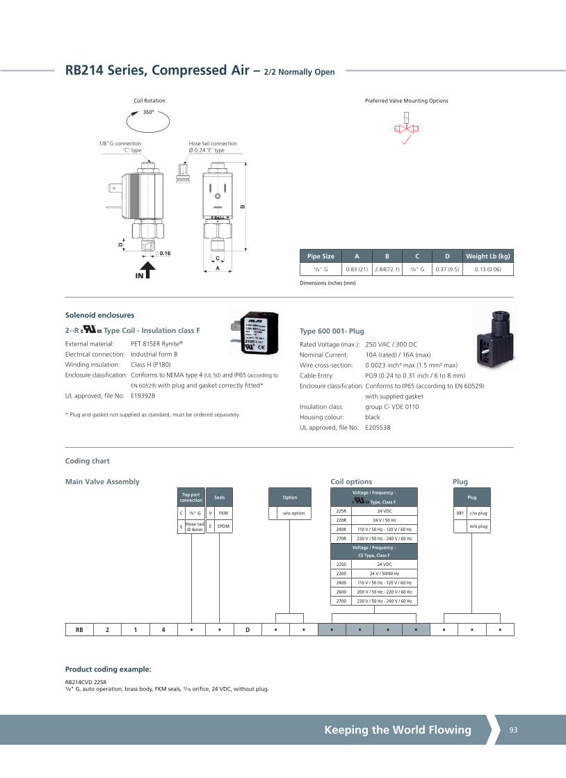
A4US
US
A4
US A4
US
A4
A4 US
US
A4
US
A4
A4 US
Keeping the World Flowing 93
RB214 Series, Compressed Air – 2/2 Normally Open
Preferred Valve Mounting Options
360º
Coil Rotation
Pipe Size A B C D Weight Lb (kg)
¹/8" G 0.83 (21) 2.84(72.1) ¹/8" G 0.37 (9.5) 0.13 (0.06)
Dimensions inches (mm)
Solenoid enclosures
Type 600 001- Plug
Rated Voltage (max.): 250 VAC / 300 DC
Nominal Current: 10A (rated) / 16A (max)
Wire cross-section: 0.0023 inch² max (1.5 mm² max)
Cable Entry: PG9 (0.24 to 0.31 inch / 6 to 8 mm)
Enclosure classification: Conforms to IP65 (according to EN 60529)
with supplied gasket
Insulation class: group C- VDE 0110
Housing colour: black
UL approved, file No: E205538
Option
w/o option
Seals
V FKM
E EPDM
Top port connection
C ¹/8” G
EHose tail Ø 6mm
Plug
0B1 c/w plug
w/o plug
Coil options Plug
Product coding example:
RB214CVD 225R ¹/8" G, auto operation, brass body, FKM seals, ¹/16 orifice, 24 VDC, without plug.
Main Valve Assembly
RB 2 1 4 • • D • • • • • • • • •
Coding chart
1/8"G connection‘C’ type
Hose tail connectionØ 0.24 ‘E’ type
IN
Voltage / Frequency -
Type, Class F
225R 24 VDC
220R 24 V / 50 Hz
240R 110 V / 50 Hz - 120 V / 60 Hz
270R 230 V / 50 Hz - 240 V / 60 Hz
Voltage / Frequency -
CE Type, Class F
2250 24 VDC
2200 24 V / 50/60 Hz
2400 110 V / 50 Hz - 120 V / 60 Hz
2600 200 V / 50 Hz - 220 V / 60 Hz
2700 230 V / 50 Hz - 240 V / 60 Hz
2--R Type Coil - Insulation class F
External material: PET 815ER Rynite®
Electrical connection: Industrial form B
Winding insulation: Class H (P180)
Enclosure classification: Conforms to NEMA type 4 (UL 50) and IP65 (according to
EN 60529) with plug and gasket correctly fitted*
UL approved, file No: E193928
* Plug and gasket not supplied as standard, must be ordered separately.

A4US
US
A4
US A4
US
A4
A4 US
US
A4
US
A4
A4 US
Solenoid Valves94
RD213 Series, Compressed Air – 2/2 Normally Open
Specifications
Function (single acting)
A
P
Maximum Viscosity Max. 21cST (3 °E)
Body Material (Std) Brass C37700 (UNS Designation)
Tube Stainless Steel AISI 304
Flange Stainless Steel AISI 303 (1.4305 EN 10088)
Plunger Stainless Steel AISI 430F (1.4106 EN 10088)
Top Stop Stainless Steel AISI 430F (1.4105 EN 10088)
Springs Stainless Steel AISI 302
Seal Material (Std) Foodgrade FKM
Connection Type (Std) G parallel thread (ISO 228-1)
Shading Ring Copper
Electrical Characteristics
Coil Voltage DC (=)24 V
Coil Voltage AC 50 Hz (~)24 V, 110 V, 230 V
Coil Voltage AC 60 Hz (~)120 V, 240 V
Voltage Tolerance +10% to -15% (AC)
+10% to -5% (DC)
Duty Cycle 100% ED
Enclosure ClassificationNEMA type 4 (UL 50) and IP65 (EN 60529)
with plug and gasket correctly fitted *
Electrical Connection to EN 175301 - 803 - A (ex DIN 43650)
Coil Insulation Class 155 (F) to UL429 and to EN 60730-1
Power Rating
( Coils)
AC 15 VA (holding)
AC 30 VA (inrush)
DC 10 W
Options Available
Seal Material2 and Media Temperature Range
Media
Ambient Temperature Range
Min Max
FKM 14 °F to 266 °F(-10 °C to +130 °C)
Water, oil, air 14 °F(-10 °C)
122 °F(+50 °C)
EPDM 14 °F to 248 °F(-10 °C to +120 °C)
Water, hot water 14 °F(-10 °C)
122 °F(+50 °C)
2 See corrosion reference guide and sealing solutions for material compatability.
Valve Options (see coding chart)
Top port connection with spherical 1/8" G
CE coils, power DC 14W - AC 18 VA
Features and Benefits
• Direct Acting
• Robust construction for industrial applications
• Zero pressure rated
• Stainless steel AISI 430F operators with low residual magnetism
• Choice of high quality seal materials
• Response time 5 to 25 ms
Pipe Size
Cv(gpm)
Kv(m3/h)
OPD psi (bar)1 Orifice inches(mm)
Seal Material
Valve CodeAC
Voltages DC
Voltages
¹/8" G 0.17 0.140 - 232(0 - 16)
0 - 232(0 - 16)
³/32 (2.5)FKM
EPDM
RD213CVG
RD213CEG
1 The valve supplied without coil carry a nameplate with pressure ratings marked in bar.

A4US
US
A4
US A4
US
A4
A4 US
US
A4
US
A4
A4 US
Keeping the World Flowing 95
Voltage / Frequency -
Type, Class F
725R 24 VDC
720R 24 V / 50 Hz
740R 110 V / 50 Hz - 120 V / 60 Hz
770R 230 V / 50 Hz - 240 V / 60 Hz
Voltage / Frequency -
CE Type, Class F
7250 24 VDC
7200 24 V / 50/60 Hz
7400 110 V / 50 Hz - 120 V / 60 Hz
7600 200 V / 50 Hz - 220 V / 60 Hz
7700 230 V / 50 Hz - 240 V / 60 Hz
Top port connection
C ¹/8" G
ASpherical
¹/8" G
RD213 Series, Compressed Air – 2/2 Normally Open
Preferred Valve Mounting Options
360º
Coil Rotation
Pipe Size A B C D Weight Lb (kg)
¹/8" G HEX 26 (26) 3.25 (82.5) 0.16 (4) 0.37 (9.5) 0.22 (0.1)
Dimensions inches (mm)
Solenoid enclosures
Type 600 011- Plug
Rated Voltage (max.): 250 VAC / 300 DC
Nominal Current: 10A (rated) / 16A (max)
Wire cross-section: 0.0023 inch² max (1.5 mm² max)
Cable Entry: PG9 (0.24 to 0.31 inch / 6 to 8 mm)
Enclosure classification: Conforms to IP65 (according to EN 60529)
with supplied gasket
Insulation class: group C- VDE 0110
Housing colour: black
UL approved, file No: E205538
Option
w/o option
Seals
V FKM
E EPDM
Plug
0A1 c/w plug
w/o plug
Coil options Plug
Product coding example:
RD213CVG 770R 0A1 ¹/8" G, auto operation, brass body, FKM seals, ³/32 orifice, 230 V / 50 Hz - 240 V / 60 Hz AC, with plug.
Main Valve Assembly
RD 2 1 3 • • G • • • • • • • • •
Coding chart
IN
Spherical 1/8"G connectioninternal Ø 0.10, ‘A’ type
1/8"G connectioninternal Ø 0.10, ‘C’ type
7--R Type Coil - Insulation class F
External material: PET 815ER Rynite®
Electrical connection: DIN EN 175301-803 form A
Winding insulation: Class H (P180)
Enclosure classification: Conforms to NEMA type 4 (UL 50) and IP65 (according to
EN 60529) with plug and gasket correctly fitted*
UL approved, file No: E193928
* Plug and gasket not supplied as standard, must be ordered separately.

A4US
US
A4
US A4
US
A4
A4 US
US
A4
US
A4
A4 US
Solenoid Valves96
D204/205/206/222 Series, Aggressive Fluids, Stainless Steel – 2/2 Normally Closed
Features and Benefits
• Pilot operated
• Robust construction for industrial applications
• Stainless steel AISI 430F operators with low
residual magnetism
• Choice of high quality seal materials
• Speed control screw as standard
• Response time 50 to 500 ms
Specifications
Function (single acting)
A
P
Flow direction overseat 1 2
Maximum Viscosity Max. 21cST (3 °E)
Body Material (Std)Stainless steel AISI 316L (ASME SA351/351M
GRADE CF3M
Flange Tube (seamless) Stainless Steel AISI 303 (1.4305 EN 10088)
Plunger Stainless Steel AISI 430F (1.4106 EN 10088)
Top Stop Stainless Steel AISI 430F (1.4105 EN 10088)
Springs Stainless Steel AISI 302
Seal Material (Std) FKM
Connection Type NPT
Shading Ring Silver
Electrical Characteristics
Coil Voltage DC (=)24 V
Coil Voltage AC 50 Hz (~)24 V, 110 V, 230 V
Coil Voltage AC 60 Hz (~)120 V, 240 V
Voltage Tolerance +10% to -15% (AC)
+10% to -5% (DC)
Duty Cycle 100% ED
Enclosure ClassificationNEMA type 4 (UL 50) and IP65 (EN 60529)
with plug and gasket correctly fitted *
Electrical Connection to EN 175301 - 803 - A (ex DIN 43650)
Coil Insulation Class 155 (F) to UL429 and to EN 60730-1
Power Rating
( Coils)
AC 15 VA (holding)
AC 30 VA (inrush)
DC 10 W
Options Available
Pipe Size
Cv(gpm)
Kv(m3/h)
OPD psi (bar) Orifice inches(mm)
Seal Material
Valve CodeAC
Voltages DC
Voltages
³/8 3.86 3.30
4 - 232
(0.3 - 16)
4 - 232
(0.3 - 16)
33/64
(13)
FKM
NBR
EPDM
D204DVZIN
D204DBZIN
D204DEZIN
1/2 4.42 3.7833/64
(13)
FKM
NBR
EPDM
D205DVZIN
D205DBZIN
D205DEZIN
3/4 9.83 8.4063/64
(25)
FKM
NBR
EPDM
D206DVYIN
D206DBYIN
D206DEYIN
1 11.23 9.6063/64
(25)
FKM
NBR
EPDM
D222DVYIN
D222DBYIN
D222DEYIN
Valve Options (see coding chart)
G parallel thread (ISO 228-1)
Manual override
Anticorrosion treatment recommended with aggressive fluids
CE coils, power DC 14W - AC 18 VA
Seal Material1 and Media Temperature Range
Media
Ambient Temperature Range
Min Max
NBR 14 °F to 194 °F (-10 °C to +90 °C)
Water, oil, air 14 °F(-10 °C)
122 °F(+50 °C)
FKM 14 °F to 266 °F(-10 °C to +130 °C)
Water, oil, air, aggressive fluids
14 °F(-10 °C)
122 °F(+50 °C)
EPDM 14 °F to 248 °F(-10 °C to +120 °C)
Water, hot water 14 °F(-10 °C)
122 °F(+50 °C)
1 See corrosion reference guide and sealing solutions for material compatability.
Vacuum Version
See separate datasheet

A4US
US
A4
US A4
US
A4
A4 US
US
A4
US
A4
A4 US
Keeping the World Flowing 97
Thread Pipe
N NPT
GAS
Voltage / Frequency -
Type, Class F
725R 24 VDC
720R 24 V / 5 0Hz
740R 110 V / 50 Hz - 120 V / 60 Hz
770R 230 V / 50 Hz - 240 V / 60 Hz
Voltage / Frequency -
CE Type, Class F
7250 24 VDC
7200 24 V / 50/60 Hz
7400 110 V / 50 Hz - 120 V / 60 Hz
7600 200 V / 50 Hz - 220 V / 60 Hz
7700 230 V / 50 Hz - 240 V / 60 Hz
Seals
V VKM
E EPDM
B NBR
Pipe Size A B C D Weight Lb (kg)
³/8 - 1/2 2.64 (67) 4.02 (102) 1.80 (45.6) 0.59 (15) 1.08 (0.49)
3/4 - 1 3.78 (96) 4.92 (125) 2.83 (72) 0.91 (23) 2.43 (1.1)
Dimensions inches (mm)
360º
Coil Rotation Preferred Valve Mounting Options
Pipe Size
04 ³/8
05 1/2
06 3/4
22 1
Plug
w/o plug
0A1 c/w plug
Coil options
Orifice1
Z 33/64
Y 63/64
Plug
1 DN 33/64 for D204 and D205, DN 63/64 for D206 and D222.
Product coding example:
Main Valve Assembly
D 2 • • D • • I N • • • • • • •
Coding chart
Solenoid enclosures
D204/205/206/222 Series, Aggressive Fluids, Stainless Steel – 2/2 Normally Closed
D204DVZIN 725R ³/8 NPT, auto operation, stainless steel body, FKM seals, 33/64 orifice, 24 VDC, without plug.
Type 600 011- Plug
Rated Voltage (max.): 250 VAC / 300 DC
Nominal Current: 10A (rated) / 16A (max)
Wire cross-section: 0.0023 inch² max (1.5 mm² max)
Cable Entry: PG9 (0.24 to 0.31 inch / 6 to 8 mm)
Enclosure classification: Conforms to IP65 (according to EN 60529)
with supplied gasket
Insulation class: group C- VDE 0110
Housing colour: black
UL approved, file No: E205538
7--R Type Coil - Insulation class F
Encapsulation material: PET 815ER Rynite®
Electrical connection: DIN EN 175301-803 form A
Winding insulation: Class H (P180)
Enclosure classification: Conforms to NEMA type 4 (UL 50) and IP65 (according to
EN 60529) with plug and gasket correctly fitted*
UL approved, file No: E193928
* Plug and gasket not supplied as standard, must be ordered separately.
Contact supplier for options.

A4US
US
A4
US A4
US
A4
A4 US
US
A4
US
A4
A4 US
Solenoid Valves98
Features and Benefits
• Pilot operated
• Robust construction for industrial applications
• Stainless steel AISI 430F operators with low
residual magnetism
• Choice of high quality seal materials
• Response time 50 to 500 ms
Specifications
Function (single acting)
A
P
Flow direction overseat 1 2
Maximum Viscosity Max. 21cST (3 °E)
Body Material (Std)Stainless steel AISI 316L (ASME SA351/351M
GRADE CF3M
Flange Tube (seamless) Stainless Steel AISI 303 (1.4305 EN 10088)
Plunger Stainless Steel AISI 430F (1.4106 EN 10088)
Top Stop Stainless Steel AISI 430F (1.4105 EN 10088)
Springs Stainless Steel AISI 302
Seal Material (Std) FKM
Connection Type NPT
Shading Ring Silver
Electrical Characteristics1
StandardCoil Voltage DC (=)
24 V
StandardCoil Voltage AC 50 Hz (~)
24 V, 110 V, 200 V, 230 V
StandardCoil Voltage AC 60 Hz (~)
24 V, 120 V, 220 V, 240 V
Voltage Tolerance +10% to -15% (AC)
+10% to -5% (DC)
Duty Cycle 100% ED
Enclosure ClassificationNEMA type 4 (UL 50) and IP65 (EN 60529)
with plug and gasket correctly fitted *
Electrical Connection to EN 175301 - 803 - A (ex DIN 43650)
Coil Insulation Class 180 (H) to EN 60730-1
Power Rating(Standard)
AC 18 VA (holding)
AC 36 VA (inrush)
DC 14 W
Options Available
Pipe Size
Cv(gpm)
Kv(m3/h)
OPD psi (bar) Orifice inches(mm)
Seal Material
Valve CodeAC
Voltages DC
Voltages
³/8 3.86 3.30
4 - 232
(0.3 - 16)
4 - 232
(0.3 - 16)
33/64
(13)
FKM
NBR
EPDM
RD204DVZIN
RD204DBZIN
RD204DEZIN
1/2 4.42 3.7833/64
(13)
FKM
NBR
EPDM
RD205DVZIN
RD205DBZIN
RD205DEZIN
3/4 9.83 8.4063/64
(25)
FKM
NBR
EPDM
RD206DVYIN
RD206DBYIN
RD206DEYIN
1 11.23 9.6063/64
(25)
FKM
NBR
EPDM
RD222DVYIN
RD222DBYIN
RD222DEYIN
Valve Options (see coding chart)
G parallel thread (ISO 228-1)
Anticorrosion treatment recommended with aggressive fluids
Seal Material2 and Media Temperature Range
Media
Ambient Temperature Range
Min Max
NBR 14 °F to 194 °F(-10 °C to +90 °C)
Water, oil, air 14 °F(-10 °C)
122 °F(+50 °C)
FKM 14 °F to 266 °F(-10 °C to +130 °C)
Water, oil, air, aggressive fluids
14 °F(-10 °C)
122 °F(+50 °C)
EPDM 14 °F to 248 °F(-10 °C to +120 °C)
Water, hot water 14 °F(-10 °C)
122 °F(+50 °C)
2 See corrosion reference guide and sealing solutions for material compatability.
RD204/205/206/222 Series, Aggressive Fluids, Stainless Steel – 2/2 Normally Open
1 These coils are not UL approved.

A4US
US
A4
US A4
US
A4
A4 US
US
A4
US
A4
A4 US
Keeping the World Flowing 99
Voltage / Frequency -
Class H
7251 24 VDC
7201 24 V / 50/60 Hz
7401 110 V / 50 Hz - 120 V / 60 Hz
7601 200 V / 50 Hz - 220 V / 60 Hz
7701 230 V / 50 Hz - 240 V / 60 Hz
Thread Pipe
N NPT
GAS
Seals
V VKM
E EPDM
B NBR
Pipe Size A B C D Weight Lb (kg)
³/8 - 1/2 2.64 (67) 3.94 (100) 1.80 (45.6) 0.59 (15) 1.08 (0.49)
3/4 - 1 3.78 (96) 4.84 (123) 2.83 (72) 0.91 (23) 2.43 (1.1)
Dimensions inches (mm)
Preferred Valve Mounting Options
Pipe Size
04 ³/8
05 1/2
06 3/4
22 1
Plug
w/o plug
0A1 c/w plug
Coil options
Orifice1
Z 33/64
Y 63/64
Plug
1 DN 33/64 for RD204 and RD205, DN 63/64 for RD206 and RD222.
Product coding example:
Main Valve Assembly
RD 2 • • D • • I N • • • • • • •
Coding chart
Solenoid enclosures
RD204/205/206/222 Series, Aggressive Fluids, Stainless Steel – 2/2 Normally Open
RD204DVZIN 7251³/8 NPT, auto operation, stainless steel body, FKM seals, 33/64 orifice, 24 VDC, without plug.
360º
Coil Rotation
Type 600 011- Plug
Rated Voltage (max.): 250 VAC / 300 DC
Nominal Current: 10A (rated) / 16A (max)
Wire cross-section: 0.0023 inch² max (1.5 mm² max)
Cable Entry: PG9 (0.24 to 0.31 inch / 6 to 8 mm)
Enclosure classification: Conforms to IP65 (according to EN 60529)
with supplied gasket
Insulation class: group C- VDE 0110
Housing colour: black
UL approved, file No: E205538
Contact supplier for options.
7--1 Type Coil - Insulation class H
External material: PPS (glass fiber & mineral filled)
Electrical connection: DIN EN 175301-803 form A
Winding insulation: Class H (E180)
Enclosure classification: Conforms to NEMA type 4 (UL 50) and IP65 (according to
EN 60529) with plug and gasket correctly fitted*
* Plug and gasket not supplied as standard, must be ordered separately.

A4US
US
A4
US A4
US
A4
A4 US
US
A4
US
A4
A4 US
Solenoid Valves100
D262/263 Series, Steam – 2/2 Normally Closed
Features and Benefits
• Direct Acting
• Robust construction for industrial applications
• Stainless steel AISI 430F operators with low residual magnetism
• High quality seal materials
• Response time 5 to 25 ms
Specifications
Function (single acting)
A
P
Flow direction overseat 1 2
Maximum Viscosity Max. 21cST (3 °E)
Body Material (Std) Brass C37700 (UNS Designation)
Orifice Material Stainless Steel AISI 303 (1.4305 EN 10088)
Flange Tube (seamless) Stainless Steel AISI 303 (1.4305 EN 10088)
Plunger Stainless Steel AISI 430F (1.4106 EN 10088)
Top Stop Stainless Steel AISI 430F (1.4105 EN 10088)
Springs Stainless Steel AISI 302
Seal Material (Std) Sigodur (filled PTFE)
Connection Type NPT
Shading Ring Copper
Electrical Characteristics
Coil Voltage DC (=)24 V
Coil Voltage AC 50 Hz (~)24 V, 110 V, 230 V
Coil Voltage AC 60 Hz (~)120 V, 240 V
Voltage Tolerance +10% to -15% (AC)
+10% to -5% (DC)
Duty Cycle 100% ED
Enclosure ClassificationNEMA type 4 (UL 50) and IP65 (EN 60529)
with plug and gasket correctly fitted *
Electrical Connection to EN 175301 - 803 - A (ex DIN 43650)
Coil Insulation Class 180 (H) to UL429 and to EN 60730-1
Power Rating
( Coils)
AC 15 VA (holding)
AC 30 VA (inrush)
DC 10 W
Options Available
Seal Material2 and Media Temperature Range
Media
Ambient Temperature Range
Min Max
Filled PTFE 14 °F to 356 °F(-10 °C to +180 °C)
Steam 14 °F(-10 °C)
158 °F(+70 °C)
2 See corrosion reference guide and sealing solutions for material compatability.
Pipe Size
Cv (gpm)
Kv (m3/h)
OPD psi (bar) Orifice inches(mm)
Seal Material
Valve CodeAC
Voltages DC
Voltages
¼ 0.04 0.03 0 - 131(0 - 9)
0 - 131(0 - 9)
³/64 (1.0) Filled PTFE D263DLAN
¼ 0.09 0.08 0 - 131(0 - 9)
0 - 131(0 - 9)
¹/16 (1.5) Filled PTFE D263DLCN
¼ 0.24 0.20 0 - 131(0 - 9)
0 - 65(0 - 4.5)
³/32 (2.5) Filled PTFE D263DLGN
¼ 0.32 0.27 0 - 131(0 - 9)
0 - 36(0 - 2.5)
¹/8 (3.0) Filled PTFE D263DLHN
Valve Options (see coding chart)
Body threaded connection 1/8
G parallel thread (ISO 228-1)
Manual override
CE coils (class H), power DC 14W - AC 18 VA1
1 Pressure ratings of valves fitted with CE coils may be higher than with UL coils(coils specifications on page 157 ).

A4US
US
A4
US A4
US
A4
A4 US
US
A4
US
A4
A4 US
Keeping the World Flowing 101
Voltage / Frequency -
Type, Class H
725H 24 VDC
720H 24 V / 50 Hz
740H 110 V / 50 Hz - 120 V / 60 Hz
770H 230 V / 50 Hz - 240 V / 60 Hz
Voltage / Frequency -
CE Type, Class H
7251 24 VDC
7201 24 V / 50/60 Hz
7401 110 V / 50 Hz - 120 V / 60 Hz
7701 230 V / 50 Hz - 240 V / 60 Hz
Thread Pipe
N NPT
GAS
Option
MManual override
w/o option
Pipe Size A B C D Weight Lb (kg)
¹/8 - ¼ 1.57 (40) 3.05 (77.5) 0.73 (18.5) 0.37 (9.5) 0.57 (0.26)
Dimensions inches (mm)
360º
Coil Rotation Preferred Valve Mounting Options
Pipe Size
2 ¹/8
3 1/4
Plug
w/o plug
0A1 c/w plug
Coil options
Orifice
A ³/64
C ¹/16
G ³/32
H ¹/8
Plug
Product coding example:
D263DLAN 720H 1/4 NPT, auto operation, brass body, filled PTFE seals, ³/64 orifice, 24 V / 50 Hz, without plug.
Main Valve Assembly
D 2 6 • D L • N • • • • • • • •
Coding chart
D262/263 Series, Steam – 2/2 Normally Closed
Solenoid enclosures
2 1
7--H Type Coil - Insulation class H
External material: PET 530HTE Rynite®
Electrical connection: DIN EN 175301-803 form A
Winding insulation: Class H (AI210)
Enclosure classification: Conforms to NEMA type 4 (UL 50) and IP65 (according to
EN 60529) with plug and gasket correctly fitted*
UL approved, file No: E193928
* Plug and gasket not supplied as standard, must be ordered separately.
Type 600 011- Plug
Rated Voltage (max.): 250 VAC / 300 DC
Nominal Current: 10A (rated) / 16A (max)
Wire cross-section: 0.0023 inch² max (1.5 mm² max)
Cable Entry: PG9 (0.24 to 0.31 inch / 6 to 8 mm)
Enclosure classification: Conforms to IP65 (according to EN 60529)
with supplied gasket
Insulation class: group C- VDE 0110
Housing colour: black
UL approved, file No: E205538

A4US
US
A4
US A4
US
A4
A4 US
US
A4
US
A4
A4 US
Solenoid Valves102
D398/399 Series, Steam – 3/2 Normally Closed
Specifications
Function (single acting)
A
PR
Flow direction underseat 2 1
Maximum Viscosity Max. 21cST (3 °E)
Body Material (Std) Stainless Steel AISI 303 (1.4305 EN 10088)
Orifice Material Stainless Steel AISI 303 (1.4305 EN 10088)
Flange Tube (seamless) Stainless Steel AISI 303 (1.4305 EN 10088)
Plunger Stainless Steel AISI 430F (1.4106 EN 10088)
Top Stop Stainless Steel AISI 430F (1.4105 EN 10088)
Springs Stainless Steel AISI 302
Seal Material (Std) Sigodur (filled PTFE)
Connection Type NPT
Shading Ring Copper
Electrical Characteristics
Coil Voltage DC (=)24 V
Coil Voltage AC 50 Hz (~)24 V, 110 V, 230 V
Coil Voltage AC 60 Hz (~)120 V, 240 V
Voltage Tolerance +10% to -15% (AC)
+10% to -5% (DC)
Duty Cycle 100% ED
Enclosure ClassificationNEMA type 4 (UL 50) and IP65 (EN 60529)
with plug and gasket correctly fitted *
Electrical Connection to EN 175301 - 803 - A (ex DIN 43650)
Coil Insulation Class 180 (H) to UL429 and to EN 60730-1
Power Rating
( Coils)
AC 15 VA (holding)
AC 30 VA (inrush)
DC 10 W
Options Available
Seal Material1 and Media Temperature Range
Media
Ambient Temperature Range
Min Max
Filled PTFE 14 °F to 356 °F(-10 °C to +180 °C)
Steam 14 °F(-10 °C)
158 °F(+70 °C)
1 See corrosion reference guide and sealing solutions for material compatability.
Valve Options (see coding chart)
Body threaded connection 1/8
G parallel thread (ISO 228-1)
Silver shading ring
CE coils, power DC 14W - AC 18 VA
Features and Benefits
• Direct Acting
• Robust construction for industrial applications
• Zero pressure rated
• Stainless steel AISI 430F operators with low residual magnetism
• High quality seal materials
• Response time 5 to 25 ms
Pipe Size
Cv(gpm)
Kv(m3/h)
OPD psi (bar) Orifice inches(mm)
Seal Material
Valve CodeAC
Voltages DC
Voltages
¼ 0.09 0.08 0 - 131(0 - 9)
0 - 131(0 - 9)
¹/16 (1.5) filled PTFE D399CLCN
¼ 0.15 0.13 0 - 131(0 - 9)
0 - 131(0 - 9)
5/64 (2.0) filled PTFE D399CLEN
¼ 0.32 0.27 0 - 73(0 - 5)
0 - 73(0 - 5)
¹/8 (3.0) filled PTFE D399CLHN

A4US
US
A4
US A4
US
A4
A4 US
US
A4
US
A4
A4 US
Keeping the World Flowing 103
Voltage / Frequency -
Type, Class H
725H 24 VDC
720H 24 V / 50 Hz
740H 110 V / 50 Hz - 120 V / 60 Hz
770H 230 V / 50 Hz - 240 V / 60 Hz
Voltage / Frequency -
CE Type, Class H
7251 24 VDC
7201 24 V / 50/60 Hz
7401 110 V / 50 Hz - 120 V / 60 Hz
7701 230 V / 50 Hz - 240 V / 60 Hz
Thread Pipe
N NPT
GAS
D398/399 Series, Steam – 3/2 Normally Closed
Preferred Valve Mounting Options
360º
Coil Rotation
Pipe Size A B C D Weight Lb (kg)
¹/8 - ¼ 1.77 (45) 3.43 (87) 0.49 (12.5) 0.61 (15.4) 0.77 (0.35)
Dimensions inches (mm)
Pipe Size
8 ¹/8”
9 1/4"
Option
ASilver
shading ring
w/o option
Plug
0A1 c/w plug
w/o plug
Coil options
Orifice
C ¹/16
E 5/64
H ¹/8
Plug
Product coding example:
D398CLEN 725H ¹/8 NPT, auto operation, stainless steel body, filled PTFE seals, 5/64 orifice, 24 VDC, without plug.
Main Valve Assembly
D 3 9 • C L • N • • • • • • • •
Coding chart
Solenoid enclosures
Type 600 011- Plug
Rated Voltage (max.): 250 VAC / 300 DC
Nominal Current: 10A (rated) / 16A (max)
Wire cross-section: 0.0023 inch² max (1.5 mm² max)
Cable Entry: PG9 (0.24 to 0.31 inch / 6 to 8 mm)
Enclosure classification: Conforms to IP65 (according to EN 60529)
with supplied gasket
Insulation class: group C- VDE 0110
Housing colour: black
UL approved, file No: E205538
2 1
7--H Type Coil - Insulation class H
External material: PET 530HTE Rynite®
Electrical connection: DIN EN 175301-803 form A
Winding insulation: Class H (AI210)
Enclosure classification: Conforms to NEMA type 4 (UL 50) and IP65 (according to
EN 60529) with plug and gasket correctly fitted*
UL approved, file No: E193928
* Plug and gasket not supplied as standard, must be ordered separately.

A4US
US
A4
US A4
US
A4
A4 US
US
A4
US
A4
A4 US
Solenoid Valves104
D238/239 Series, Steam – 2/2 Normally Closed
Features and Benefits
• Direct Acting
• Robust construction for industrial applications
• Stainless steel AISI 430F operators with low residual magnetism
• High quality seal materials
• Response time 5 to 25 ms
Pipe Size
Cv(gpm)
Kv(m3/h)
OPD psi (bar) Orifice inches(mm)
Seal Material
Valve CodeAC
Voltages DC
Voltages
³/8 0.32 0.27 0 - 131(0 - 9)
0 - 116(0 - 8)
¹/8 (3.0) Filled PTFE D238DLHN
³/8 0.53 0.45 0 - 73(0 - 5)
0 - 29(0 - 2)
13/64 (5.0) Filled PTFE D238DLNN
1/2 0.35 0.30 0 - 131(0 - 9)
0 - 73(0 - 5)
¹/8 (3.5) Filled PTFE D239DLIN
Specifications
Function (single acting)
A
P
Flow direction overseat 1 2
Maximum Viscosity Max. 21cST (3 °E)
Body Material (Std) Brass C37700 (UNS Designation)
Orifice Material Stainless Steel AISI 303 (1.4305 EN 10088)
Flange Tube (seamless) Stainless Steel AISI 303 (1.4305 EN 10088)
Plunger Stainless Steel AISI 430F (1.4106 EN 10088)
Top Stop Stainless Steel AISI 430F (1.4105 EN 10088)
Springs Stainless Steel AISI 302
Seal Material (Std) Sigodur (filled PTFE)
Connection Type NPT
Shading Ring Copper
Electrical Characteristics1
StandardCoil Voltage DC (=)
24 V
StandardCoil Voltage AC 50 Hz (~)
24 V, 110 V, 200 V, 230 V
StandardCoil Voltage AC 60 Hz (~)
24 V, 120 V, 220 V, 240 V
Voltage Tolerance +10% to -15% (AC)
+10% to -5% (DC)
Duty Cycle 100% ED
Enclosure classificationNEMA type 4 (UL 50) and IP65 (EN 60529)
with plug and gasket correctly fitted *
Electrical Connection to EN 175301 - 803 - A (ex DIN 43650)
Coil Insulation Class 180 (H) to EN 60730-1
Power Rating(Standard)
AC 18 VA (holding)
AC 36 VA (inrush)
DC 14 W
Seal Material2 and Media Temperature Range
Media
Ambient Temperature Range
Min Max
Filled PTFE 14 °F to 356 °F(-10 °C to +180 °C)
Steam14 °F
(-10 °C)158 °F
(+70 °C)
2 See corrosion reference guide and sealing solutions for material compatability.
Options Available
Valve Options (see coding chart)
G parallel thread (ISO 228-1)
1 High power coils are not UL approved.

A4US
US
A4
US A4
US
A4
A4 US
US
A4
US
A4
A4 US
Keeping the World Flowing 105
Voltage / Frequency -
Class H
7251 24 VDC
7201 24 V / 50/60 Hz
7401 110 V / 50 Hz - 120 V / 60 Hz
7601 200 V / 50 Hz - 220 V / 60 Hz
7701 230 V / 50 Hz - 240 V / 60 Hz
Thread Pipe
N NPT
GAS
Orifice
H ¹/8
I ¹/8
N 13/64
Plug
w/o plug
0A1 c/w plug
D238/239 Series, Steam – 2/2 Normally Closed
Option
w/o option
Pipe Size A B C D Weight Lb (kg)
³/8 - 1/2 2.13 (54) 3.52 (89.35) HEX 27 (27) 0.59 (15) 0.99 (0.45)
Dimensions inches (mm)
360º
Coil Rotation Preferred Valve Mounting Options
Pipe Size
8 ³/8"
9 1/2"
Coil options Plug
Product coding example:D238DLHN 7251 ³/8 NPT, auto operation, brass body, filled PTFE seals, ¹/8 orifice, 24 VDC, without plug.
Main Valve Assembly
Coding chart
Solenoid enclosures
D 2 3 • D L • N • • • • • • • •
Type 600 011- Plug
Rated Voltage (max.): 250 VAC / 300 DC
Nominal Current: 10A (rated) / 16A (max)
Wire cross-section: 0.0023 inch² max (1.5 mm² max)
Cable Entry: PG9 (0.24 to 0.31 inch / 6 to 8 mm)
Enclosure classification: Conforms to IP65 (according to EN 60529)
with supplied gasket
Insulation class: group C- VDE 0110
Housing colour: black
UL approved, file No: E205538
7--1 Type Coil - Insulation class H
External material: PPS (glass fiber & mineral filled)
Electrical connection: DIN EN 175301-803 form A
Winding insulation: Class H (E180)
Enclosure classification: Conforms to NEMA type 4 (UL 50) and IP65 (according to
EN 60529) with plug and gasket correctly fitted*
* Plug and gasket not supplied as standard, must be ordered separately.

A4US
US
A4
US A4
US
A4
A4 US
US
A4
US
A4
A4 US
Solenoid Valves106
D634/635/636 Series, Steam – 2/2 Normally Closed
Features and Benefits
• Pilot operated
• Robust construction for industrial applications
• Stainless steel AISI 430F operators with low residual magnetism
• Coils tested 100% in compliance to RoHS directive and to relevant international standards
• High quality seal materials
• Response time 50 to 500 ms
Pipe Size
Cv(gpm)
Kv(m3/h)
OPD psi (bar) Orifice inches(mm)
Seal Material
Valve CodeAC
Voltages DC
Voltages
¼ 1.47 1.26
4.4 - 131(0.3 - 9)
4.4 - 131(0.3 - 9)
25/64 (10) PTFE D634DTTN
³/8 1.68 1.44 25/64 (10) PTFE D635DTTN
1/2 1.76 1.50 25/64 (10) PTFE D636DTTN
Specifications
Function (single acting)
A
P
Flow direction overseat 1 2
Maximum Viscosity Max. 21cST (3 °E)
Body Material (Std) Brass C37700 (UNS Designation)
Orifice Material Stainless Steel AISI 303 (1.4305 EN 10088)
Flange Tube (seamless) Stainless Steel AISI 303 (1.4305 EN 10088)
Plunger Stainless Steel AISI 430F (1.4106 EN 10088)
Top Stop Stainless Steel AISI 430F (1.4105 EN 10088)
Piston Material Brass C37700 (UNS Designation)
Springs Stainless Steel AISI 302
Seal Material (Std) PTFE
Connection Type NPT
Shading Ring Copper
Electrical Characteristics1
High Power
Coil Voltage DC (=)24 V
StandardCoil Voltage AC 50 Hz (~)
24 V, 110 V, 200 V, 230 V
StandardCoil Voltage AC 60 Hz (~)
24 V, 120 V, 220 V, 240 V
Voltage Tolerance +10% to -15% (AC)
+10% to -5% (DC)
Duty Cycle 100% ED
Enclosure ClassificationNEMA type 4 (UL 50) and IP65 (EN 60529)
with plug and gasket correctly fitted *
Electrical Connection to EN 175301 - 803 - A (ex DIN 43650)
Coil Insulation Class 180 (H) to EN 60730-1
Power Rating(Standard)
AC 18 VA (holding)
AC 36 VA (inrush)
DC 22 W
Seal Material2 and Media Temperature Range
Media
Ambient Temperature Range
Min Max
PTFE 176 °F3 to 356 °F(+80 °C3 to +180 °C)
Steam 14 °F(-10 °C)
158 °F(+70 °C)
2 See corrosion reference guide and sealing solutions for material compatability.3 For correct funtioning, the minimum working temperature of the solenoid valve cannot be below
176 °F (+80 °C).
1 For DC only High Power coil mandatory, these coils are not UL approved.
Options Available
Valve Options (see coding chart)
G parallel thread (ISO 228-1)

A4US
US
A4
US A4
US
A4
A4 US
US
A4
US
A4
A4 US
Keeping the World Flowing 107
Thread Pipe
N NPT
GAS
D634/635/636 Series, Steam – 2/2 Normally Closed
Option
w/o option
Pipe Size A B C D Weight Lb (kg)
¼ 2.13 (54) 3.94 (100) HEX 27 (27) 0.59 (15) 1.10 (0.5)
³/8 to 1/2 2.13 (54) 3.94 (100) HEX 27 (27) 0.59 (15) 0.99 (0.45)
Dimensions inches (mm)
Preferred Valve Mounting Options
Pipe Size
4 1/4
5 ³/8
6 1/2
Plug
w/o plug
0A1 c/w plug
Coil options Plug
Product coding example:D634DTTN 72Z1 1/4 NPT, auto operation, brass body, PTFE seals, 25/64 orifice, 24 VDC, without plug.
Main Valve Assembly
Coding chart
Voltage / Frequency -
Class H (High Power DC only)
72Z1 24 VDC
7201 24 V / 50/60 Hz
7401 110 V / 50 Hz - 120 V / 60 Hz
7601 200 V / 50 Hz - 220 V / 60 Hz
7701 230 V / 50 Hz - 240 V / 60 Hz
D 6 3 • D T T N • • • • • • • •
Solenoid enclosures
360º
Coil Rotation
7--1 & 7-Z1 Type Coil - Insulation class H
External material: PPS (glass fiber & mineral filled)
Electrical connection: DIN EN 175301-803 form A
Winding insulation: Class H (E180)
Enclosure classification: Conforms to NEMA type 4 (UL 50) and IP65 (according to
EN 60529) with plug and gasket correctly fitted*
* Plug and gasket not supplied as standard, must be ordered separately.
Type 600 011- Plug
Rated Voltage (max.): 250 VAC / 300 DC
Nominal Current: 10A (rated) / 16A (max)
Wire cross-section: 0.0023 inch² max (1.5 mm² max)
Cable Entry: PG9 (0.24 to 0.31 inch / 6 to 8 mm)
Enclosure classification: Conforms to IP65 (according to EN 60529)
with supplied gasket
Insulation class: group C- VDE 0110
Housing colour: black
UL approved, file No: E205538

A4US
US
A4
US A4
US
A4
A4 US
US
A4
US
A4
A4 US
Solenoid Valves108
UACPX Series: Steam – 2/2 Normally Closed
Features and Benefits
• Heavy Duty Valve Design
• Piston Operation
• Wide temperature range capabilities
• Choice of valve body material seals
• Tested in accordance with BS-EN 12266-1
Specifications
Mode of Operation
Normally closed, energise to open
Maximum Viscosity 115 SSU
3/8” - 1” Body Material (Std)
Brass (Std) or Stainless Steel option
11/4” - 2” Body Material (Std)
Bronze (Std)
Flange Tube Stainless Steel
Plunger and top stop Stainless Steel
Springs Stainless Steel
Seal Material PTFE
Connection Type NPT
Shading Ring Copper (std), Silver (stainless steel option)
Electrical Characteristics
Coil Voltage DC (=) 12 V, 24 V
Coil Voltage AC 60 Hz (~)
24 V, 120 V
Voltage Tolerance +10% or -10%
Duty Cycle 100% ED
Electrical Connection options
1/2” NPT metal conduit hub with 18” leads (NEMA 2 equivalent protection class)
Coil Insulation Class H
Power Rating 14.5 Watts
Out (2)
In (1)
Options Available
Main Valve Body Options
Stainless Steel 316 (up to and including 1")
Oxygen Cleaning (consult factory for product code)
Stainless Steel Tagging (consult factory for product code)
Solenoid Enclosure
Protection Class
EExd T6 (NEMA 6 equivalent) Consult Rotork Midland
for product codesEExd T4 (NEMA 6 equivalent)
Port Size
Cv Kv
OPD (psi)P. Max2
psiOrifice (mm)
Weight (lbs)AC
Voltages DC
Voltages
1/2” 4.9 4.2 5-125 5-70
725
16.0 2.8
3/4” 6.3 5.4 5-125 5-70 16.0 2.8
1” 8.2 7.1 5-125 5-70 25.0 5
1¼” 20.9 18 5-125 5-70 30.0 6.8
11/2” 20.9 18 5-125 5-70 30.0 6.8
2” 24.4 21 5-125 5-70 32.0 11.5
1 See corrosion reference guide and sealing solutions for material compatability.
2 P. Max is limited to 675 psi when valve is fitted with an Exd solenoid operator.
1. Select the required flow.
2. Note the corresponding pressure drop.
3. Based on where the two points intersect select the most appropriate model.
How to use the flow chart
Flow shown is with steam at 58 psi
Seal Material1 and Media Temp. Range
Ambient Temperature Range
Min Max
PTFE (-328 ºF to +356 ºF) 14 ºF 122 ºF
Steam flow lb/hr
Pressure drop (PSI)
Pres
sure
dro
p (B
ar)
Steam flow kg/hr1
0.1
1
10
10010 1000
150
2200100050020010050201052.2
50
10
3
1.5
1¼"
& 11/2
" va
lve -
30.0
mm
orifi
ce
1" v
alve
- 25
.0 m
m o
rifice
1/2"
valve
- 16
.0 m
m o
rifice
2" v
alve
- 32
.0 m
m o
rifice

A4US
US
A4
US A4
US
A4
A4 US
US
A4
US
A4
A4 US
Keeping the World Flowing 109
UACPX Series: Steam – 2/2 Normally Closed
Preferred Valve Mounting Options
Solenoid enclosures
Product coding example:
22D31Z1E1-2H29A: UACPX Series 1/2” NPT, Auto, Brass body, PTFE seals, 120 V / 60 Hz, 1/2” NPT electrical connection UL/CSA approval.
S4 Type enclosure protection class IP50
External material: Pressed steel powder coated
Electrical entry: 1/2” NPT metal conduit hub with 18” leads (NEMA 2 equivalent protection class)
Winding Insulation: Class H
Main Valve Assembly Coil options
Dimensions given in inches
Dimensions
Port size A B C D
3/4" 21/2" 41/8" 21/4" 413/16"
1" 41/4" 415/16" 3" 53/4"
11/4" - 11/2" 45/8" 51/4" 31/4" 81/4"
2" 53/4" 53/4" 4" 81/4"
Voltage / Frequency
F1 24 VDC
F4 12 VDC
H124 V / 60 Hz
H2120 V / 60 Hz
Electrical connection
91/2” NPT
2 •• 9 A
Valve Body Conn. Size
D 1/2”
E 3/4”
F 1”
G 11/4”
H 11/2”
J 2”
Operation
1 AUTO
Conn. Type
3 NPT
Seals
E PTFE
Style
1 Standard
Body Material
1
Brass (standard on valves up to and
including 1”)
2
Bronze (standard on valves above 1”)
5
316 Stainless Steel (option available up to
and inc 1”)
22 • 3 1 Z • E 1 -
Orifice (mm)
Z Default
Enclosure
2
S4 type enclosure
-metal can
(IP50) UL Approved
Approval
AUL/CSA
Model
22 UACPX
360º
Coil Rotation
BD
A C
Coding chart

A4US
US
A4
US A4
US
A4
A4 US
US
A4
US
A4
A4 US
Solenoid Valves110
RD236 Series, Steam – 2/2 Normally Open
Specifications
Function (single acting)
A
P
Flow direction 1 2
Maximum Viscosity Max. 21cST (3 °E)
Body Material (Std) Brass C37700 (UNS Designation)
Orifice Material Stainless Steel AISI 303 (1.4305 EN 10088)
Flange Tube (seamless) Stainless Steel AISI 303 (1.4305 EN 10088)
Plunger Stainless Steel AISI 430F (1.4106 EN 10088)
Top Stop Stainless Steel AISI 430F (1.4105 EN 10088)
Springs Stainless Steel AISI 302
Seal Material (Std) Sigodur (filled PTFE)
Connection Type (Std) G parallel thread (ISO 228-1)
Shading Ring Copper
Electrical Characteristics1
StandardCoil Voltage DC (=)
24 V
StandardCoil Voltage AC 50 Hz (~)
24 V, 110 V, 200 V, 230 V
StandardCoil Voltage AC 60 Hz (~)
24 V, 120 V, 220 V, 240 V
Voltage Tolerance +10% to -15% (AC)
+10% to -5% (DC)
Duty Cycle 100% ED
Enclosure ClassificationNEMA type 4 (UL 50) and IP65 (EN 60529)
with plug and gasket correctly fitted *
Electrical Connection to EN 175301 - 803 - A (ex DIN 43650)
Coil Insulation Class 180 (H) to EN 60730-1
Power Rating(Standard)
AC 18 VA (holding)
AC 36 VA (inrush)
DC 14 W
Seal Material3 and Media Temperature Range
Media
Ambient Temperature Range
Min Max
Filled PTFE 14 °F to 356 °F(-10 °C to +180 °C)
Steam 14 °F(-10 °C)
158 °F(+70 °C)
3 See corrosion reference guide and sealing solutions for material compatability.
Features and Benefits
• Direct Acting
• Robust construction for industrial applications
• Zero pressure rated
• Stainless steel AISI 430F operators with low residual magnetism
• High quality seal materials
• Response time 5 to 25 ms
Pipe Size
Cv(gpm)
Kv(m3/h)
OPD psi (bar)2 Orifice inches(mm)
Seal Material
Valve CodeAC
Voltages DC
Voltages
¼" 0.04 0.030 - 131
(0 - 9)
0 - 131(0 - 9)
³/64 (1.0) filled PTFE RD236DLA
¼" 0.09 0.080 - 131
(0 - 9)
0 - 131(0 - 9)
¹/16 (1.5) filled PTFE RD236DLC
¼" 0.14 0.120 - 131
(0 - 9)
0 - 131(0 - 9)
5/64 (2.0) filled PTFE RD236DLE
¼" 0.25 0.210 - 131
(0 - 9)
0 - 131(0 - 9)
¹/8 (3.0) filled PTFE RD236DLH
2 The valve supplied carry a nameplate with pressure ratings marked in bar.
Options Available
1 These coils are not UL approved.

A4US
US
A4
US A4
US
A4
A4 US
US
A4
US
A4
A4 US
Keeping the World Flowing 111
Voltage / Frequency -
Class H
7251 24 DC
7201 24 V / 50/60 Hz
7401 110 V / 50 Hz - 120 V / 60Hz
7601 200 V / 50 Hz - 220 V / 60Hz
7701 230 V / 50 Hz - 240 V / 60Hz
RD236 Series, Steam – 2/2 Normally Open
Preferred Valve Mounting Options
360º
Coil Rotation
Pipe Size A B C D Weight Lb (kg)
¼" G 1.85 (47) 2.58 (91) HEX 22 (22) 0.82 (20.75) 0.55 (0.25)
Dimensions inches (mm)
Solenoid enclosures
Type 600 011- Plug
Rated Voltage (max.): 250 VAC / 300 DC
Nominal Current: 10A (rated) / 16A (max)
Wire cross-section: 0.0023 inch² max (1.5 mm² max)
Cable Entry: PG9 (0.24 to 0.31 inch / 6 to 8 mm)
Enclosure classification: Conforms to IP65 (according to EN 60529)
with supplied gasket
Insulation class: group C- VDE 0110
Housing colour: black
UL approved, file No: E205538
Option
w/o option
Plug
0A1 c/w plug
w/o plug
Coil options
Orifice
A ³/64
C ¹/16
E 5/64
H ¹/8
Plug
Product coding example:
RD236DLE 7251 1/4" G, auto operation, brass body, filled PTFE seals, 5/64 orifice, 24 VDC, without plug.
Main Valve Assembly
RD 2 3 6 D L • • • • • • • • • •
Coding chart
2 fixing holes M4x7
1 2
7--1 Type Coil - Insulation class H
External material: PPS (glass fiber & mineral filled)
Electrical connection: DIN EN 175301-803 form A
Winding insulation: Class H (E180)
Enclosure classification: Conforms to NEMA type 4 (UL 50) and IP65 (according to
EN 60529) with plug and gasket correctly fitted*
* Plug and gasket not supplied as standard, must be ordered separately.

A4US
US
A4
US A4
US
A4
A4 US
US
A4
US
A4
A4 US
Solenoid Valves112
D606/622 Series, Steam – 2/2 Normally Closed
Specifications
Function NC (single acting)
A
P
Flow direction overseat 1 2
Maximum Viscosity Max. 21cST (3 °E)
Body Material (Std) Brass C37700 (UNS Designation)
Orifice Material Stainless Steel AISI 303 (1.4305 EN 10088)
Flange Tube (seamless) Stainless Steel AISI 303 (1.4305 EN 10088)
Plunger Stainless Steel AISI 430F (1.4106 EN 10088)
Top Stop Stainless Steel AISI 430F (1.4105 EN 10088)
Springs Stainless Steel AISI 302
Seal Material (Std) PTFE
Connection Type NPT
Shading Ring Copper
Electrical Characteristics
Coil Voltage DC (=)24 V
Coil Voltage AC 50 Hz (~)24 V, 110 V, 230 V
Coil Voltage AC 60 Hz (~)120 V, 240 V
Voltage Tolerance +10% to -15% (AC)
+10% to -5% (DC)
Duty Cycle 100% ED
Enclosure ClassificationNEMA type 4 (UL 50) and IP65 (EN 60529)
with plug and gasket correctly fitted *
Electrical Connection to EN 175301 - 803 - A (ex DIN 43650)
Coil Insulation Class 180 (H) to UL429 and to EN 60730-1
Power Rating
( Coils)
AC 15 VA (holding)
AC 30 VA (inrush)
DC 10 W
Options Available
Seal Material1 and Media Temperature Range
Media2
Ambient Temperature Range
Min Max
Filled PTFE 176 °F3 to 356 °F(+80 °C3 to +180 °C)
Steam 14 °F(-10 °C)
158 °F(+70 °C)
Valve Options (see coding chart)
G parallel thread (ISO 228-1)
CE coils, power DC 14W - AC 18 VA
Features and Benefits
• Direct Acting
• Robust construction for industrial applications
• Zero pressure rated
• Stainless steel AISI 430F operators with low residual magnetism
• High quality seal material
• Response time 5 to 25 ms
Pipe Size
Cv (gpm)
Kv (m3/h)
OPD psi (bar) Orifice inches(mm)
Seal Material
Valve CodeAC
Voltages DC
Voltages
3/4 8.42 7.2014.5 - 131
(1 - 9)
14.5 - 131(1 - 9)
61/64 (24) PTFE D606DTYN
1 8.42 7.2014.5 - 131
(1 - 9)
14.5 - 131(1 - 9)
61/64 (24) PTFE D622DTYN
1 See corrosion reference guide and sealing solutions for material compatability.2 Water and high content of condensate can damage the diaphragm.3 For a correct functioning, the minimum working temperature of the solenoid valve cannot be
below 356 °F (+80 °C).

A4US
US
A4
US A4
US
A4
A4 US
US
A4
US
A4
A4 US
Keeping the World Flowing 113
Voltage / Frequency -
Type, Class H
725H 24 VDC
720H 24 V / 50 Hz
740H 110 V / 50 Hz - 120 V / 60 Hz
770H 230 V / 50 Hz - 240 V / 60 Hz
Voltage / Frequency -
CE Type, Class H
7251 24 VDC
7201 24 V / 50/60 Hz
7401 110 V / 50 Hz - 120 V / 60 Hz
7701 230 V / 50 Hz - 240 V / 60 Hz
Option
w/o option
Thread Pipe
N NPT
GAS
Pipe Size
06 3/4
22 1
Preferred Valve Mounting Options
360º
Coil Rotation
Pipe Size A B C D Weight Lb (kg)
3/4" - 1" 3.78 (96) 4.96 (126) 2.83 (72) 0.94 (24) 2.87 (1.3)
Dimensions inches (mm)
Plug
0A1 c/w plug
w/o plug
Coil options Plug
Product coding example:
D606DTYN 725H 3/4 NPT, auto operation, brass body, PTFE seals, 61/64 orifice, 24 VDC, without plug.
Main Valve Assembly
Coding chart
D606/622 Series, Steam – 2/2 Normally Closed
D 6 • • D T Y N • • • • • • • •
Solenoid enclosures
Type 600 011- Plug
Rated Voltage (max.): 250 VAC / 300 DC
Nominal Current: 10A (rated) / 16A (max)
Wire cross-section: 0.0023 inch² max (1.5 mm² max)
Cable Entry: PG9 (0.24 to 0.31 inch / 6 to 8 mm)
Enclosure classification: Conforms to IP65 (according to EN 60529)
with supplied gasket
Insulation class: group C- VDE 0110
Housing colour: black
UL approved, file No: E205538
7--H Type Coil - Insulation class H
External material: PET 530HTE Rynite®
Electrical connection: DIN EN 175301-803 form A
Winding insulation: Class H (AI210)
Enclosure classification: Conforms to NEMA type 4 (UL 50) and IP65 (according to
EN 60529) with plug and gasket correctly fitted*
UL approved, file No: E193928
* Plug and gasket not supplied as standard, must be ordered separately.

A4US
US
A4
US A4
US
A4
A4 US
US
A4
US
A4
A4 US
Solenoid Valves114
D211 Series, Dry Armature – 2/2 Normally Closed
Specifications
Function (single acting)
A
P
Maximum Viscosity Max. 21cST (3 °E)
Body Material (Std) Brass C37700 (UNS Designation)
Orifice Material Stainless Steel AISI 303 (1.4305 EN 10088)
Flange Tube (seamless) Stainless Steel AISI 303 (1.4305 EN 10088)
Plunger Stainless Steel AISI 430F (1.4106 EN 10088)
Top Stop Stainless Steel AISI 430F (1.4105 EN 10088)
Springs Stainless Steel AISI 302
Seal Material (Std) Silicone FDA compliant
Connection Type (Std) G parallel thread (ISO 228-1)
Shading Ring Copper
Electrical Characteristics1
StandardCoil Voltage DC (=)
24 V
StandardCoil Voltage AC 50 Hz (~)
24 V, 110 V, 200 V, 230 V
StandardCoil Voltage AC 60 Hz (~)
24 V, 120 V, 220 V, 240 V
Voltage Tolerance +10% to -15% (AC)
+10% to -5% (DC)
Duty Cycle 100% ED
Enclosure ClassificationNEMA type 4 (UL 50) and IP65 (EN 60529)
with plug and gasket correctly fitted *
Electrical Connection to EN 175301 - 803 - A (ex DIN 43650)
Coil Insulation Class 155 (F) to UL429 and to EN 60730-1
Power Rating(Standard)
AC 18 VA (holding)
AC 36 VA (inrush)
DC 14 W
Seal Material3 and Media Temperature Range
Media
Ambient Temperature Range
Min Max
Silicone FDA compliant 14 °F to 203 °F(-10 °C to +95 °C)
Water and beverages
14 °F(-10 °C)
122 °F(+50 °C)
3 See corrosion reference guide and sealing solutions for material compatability.
Valve Options (see coding chart)
Electroless nickel plating
Features and Benefits
• Direct Acting
• Robust construction for industrial applications
• Zero pressure rated
• Stainless steel AISI 430F operators with low residual magnetism
• High quality seal material
• Total separation between internal parts and medium
• Response time 5 to 25 ms
Pipe Size
Cv(gpm)
Kv(m3/h)
OPD bar2 Orifice inches(mm)
Seal Material
Valve CodeAC
Voltages DC
Voltages
³/8" G
see flow chart
0 - 0.3 - 13/32 (10.5) Silicone FDA D211DSU
³/8" G - 0 - 0.2 13/32 (10.5) Silicone FDA CD211DSU
How to use the flow chart- Select the required flow.
- Note the corresponding pressure drop.
- Based on where the two points intersect select the most appropriate model.
Flow
rat
e in
cm
3 /se
cond
Water head in mm
Flow chart
2 This valve supplied with a nameplate with pressure ratings marked in bar.
Options Available
1 These coils are not UL approved.

A4US
US
A4
US A4
US
A4
A4 US
US
A4
US
A4
A4 US
Keeping the World Flowing 115
Voltage / Frequency -
CE Type, Class F
7250 24 VDC
7200 24 V / 50/60 Hz
7400 110 V / 50 Hz - 120 V / 60 Hz
7600 200 V / 50 Hz - 220 V / 60 Hz
7700 230 V / 50 Hz - 240 V / 60 Hz
Preferred Valve Mounting Options
360º
Coil Rotation
Pipe Size A B C D Weight Lb (kg)
³/8" G 1.71 (43.4) 3.50 (88.8) 1.42 (36) 0.87 (22) 0.75 (0.34)
Dimensions inches (mm)
Option
KElectroless
nickel plating
w/o option
Plug
0A1 c/w plug
w/o plug
Coil options Plug
Product coding example:D211DSU 7250 ³/8" G, auto operation, brass body, silicone FDA seals, 13/32 orifice, 24 VDC, without plug.
Main Valve Assembly
Coding chart
Valve Type
D AC
CD DC
D211 Series, Dry Armature – 2/2 Normally Closed
• 2 1 1 D S U • • • • • • • • •
Solenoid enclosures
Type 600 011- Plug
Rated Voltage (max.): 250 VAC / 300 DC
Nominal Current: 10A (rated) / 16A (max)
Wire cross-section: 0.0023 inch² max (1.5 mm² max)
Cable Entry: PG9 (0.24 to 0.31 inch / 6 to 8 mm)
Enclosure classification: Conforms to IP65 (according to EN 60529)
with supplied gasket
Insulation class: group C- VDE 0110
Housing colour: black
UL approved, file No: E205538
7--0 Type Coil - Insulation class F
External material: PBT (reinforced glass fiber 30%)
Electrical connection: DIN EN 175301-803 form A
Winding insulation: Class H (E180)
Enclosure classification: Conforms to NEMA type 4 (UL 50) and IP65 (according to
EN 60529) with plug and gasket correctly fitted*
* Plug and gasket not supplied as standard, must be ordered separately.

A4US
US
A4
US A4
US
A4
A4 US
US
A4
US
A4
A4 US
Solenoid Valves116
D262/263 Series, Vacuum – 2/2 Normally Closed
Features and Benefits
• Direct Acting
• Robust construction for industrial applications
• Configuration suitable for vacuum
• Stainless steel AISI 430F operators with low residual magnetism
• Choice of high quality seal materials
• Response time 5 to 25 ms
Specifications
Function (single acting)
A
P
Flow direction overseat 1 2
Maximum Viscosity Max. 21cST (3 °E)
Body Material (Std) Brass C37700 (UNS Designation)
Orifice Material Stainless Steel AISI 303 (1.4305 EN 10088)
Flange Stainless Steel AISI 303 (1.4305 EN 10088)
Tube Stainless Steel AISI 304
Plunger Stainless Steel AISI 430F (1.4106 EN 10088)
Top Stop Stainless Steel AISI 430F (1.4105 EN 10088)
Springs Stainless Steel AISI 302
Seal Material (Std) Foodgrade FKM
Connection Type NPT
Shading Ring Copper
Electrical Characteristics
Coil Voltage DC (=)24 V
Coil Voltage AC 50 Hz (~)24 V, 110 V, 230 V
Coil Voltage AC 60 Hz (~)120 V, 240 V
Voltage Tolerance +10% to -15% (AC)
+10% to -5% (DC)
Duty Cycle 100% ED
Enclosure ClassificationNEMA type 4 (UL 50) and IP65 (EN 60529)
with plug and gasket correctly fitted *
Electrical Connection to EN 175301 - 803 - A (ex DIN 43650)
Coil Insulation Class 155 (F) to UL429 and to EN 60730-1
Power Rating
( Coils)
AC 15 VA (holding)
AC 30 VA (inrush)
DC 14 W
Seal Material1 and Media Temperature Range
Media
Ambient Temperature Range
Min Max
FKM 14 °F to 266 °F(-10 °C to +130 °C)
Water, oil, air 14 °F(-10 °C)
122 °F(+50 °C)
NBR 14 °F to 194 °F(-10 °C to +90 °C)
Water, oil, air 14 °F(-10 °C)
122 °F(+50 °C)
1 See corrosion reference guide and sealing solutions for material compatability.
Other seals material on request.
Pipe Size
Cv (gpm)
Kv (m3/h)
OPD psi (bar) Orifice inches(mm)
Seal Material
Valve CodeAC
Voltages DC
Voltages
¼ 0.04 0.03-13.1 to 14.5
(-0.9 to 1)
-13.1 to 14.5(-0.9 to 1)
³/64 (1.0)FKM
NBR
D263DVANL
D263DBANL
¼ 0.09 0.08-13.1 to 14.5
(-0.9 to 1)
-13.1 to 14.5(-0.9 to 1)
¹/16 (1.5)FKM
NBR
D263DVCNL
D263DBCNL
¼ 0.24 0.20-13.1 to 14.5
(-0.9 to 1)
-13.1 to 14.5(-0.9 to 1)
³/32 (2.5)FKM
NBR
D263DVGNL
D263DBGNL
¼ 0.32 0.27-13.1 to 14.5
(-0.9 to 1)
-13.1 to 14.5(-0.9 to 1)
¹/8 (3.0)FKM
NBR
D263DVHNL
D263DBHNL
¼ 0.42 0.36-13.1 to 14.5
(-0.9 to 1)
-13.1 to 14.5(-0.9 to 1)
5/32 (4.0)FKM
NBR
D263DVLNL
D263DBLNL
¼ 0.56 0.48-13.1 to 14.5
(-0.9 to 1)
-13.1 to 14.5(-0.9 to 1)
15/64 (6.0)FKM
NBR
D263DVPNL
D263DBPNL
Options Available
Valve Options (see coding chart)
Body threaded connection 1/8
G parallel thread (ISO 228-1)
CE coils, power DC 14W - AC 18 VA

A4US
US
A4
US A4
US
A4
A4 US
US
A4
US
A4
A4 US
Keeping the World Flowing 117
Thread Pipe
N NPT
GAS
Voltage / Frequency -
Type, Class F
725R 24 VDC
720R 24 V / 50 Hz
740R 110 V / 50 Hz - 120 V / 60 Hz
770R 230 V / 50 Hz - 240 V / 60 Hz
Voltage / Frequency -
CE Type, Class F
7250 24 VDC
7200 24 V / 50/60 Hz
7400 110 V / 50 Hz - 120 V / 60 Hz
7600 200 V / 50 Hz - 220 V / 60 Hz
7700 230 V / 50 Hz - 240 V / 60 Hz
Seals
V FKM
B NBR
Pipe Size A B C D Weight Lb (kg)
¹/8" - ¼ 1.57 (40) 3.05 (77.5) 0.73 (18.5) 0.37 (9.5) 0.57 (0.26)
Dimensions inches (mm)
360º
Coil Rotation
Pipe Size
2 ¹/8
3 1/4
Plug
w/o plug
0A1 c/w plug
Coil options
Orifice
A ³/64
C ¹/16
G ³/32
H ¹/8
L 5/32
P 15/64
Plug
Product coding example:D263DBPNL 770R 1/4 NPT, auto operation, brass body, FKM seals, 15/64 orifice, 230 V / 50 Hz - 240 V / 60 Hz, without plug.
Main Valve Assembly
D 2 6 • D • • N L • • • • • • •
Coding chart
D262/263 Series, Vacuum – 2/2 Normally Closed
Solenoid enclosures
Connection scheme
Type 600 011- Plug
Rated Voltage (max.): 250 VAC / 300 DC
Nominal Current: 10A (rated) / 16A (max)
Wire cross-section: 0.0023 inch² max (1.5 mm² max)
Cable Entry: PG9 (0.24 to 0.31 inch / 6 to 8 mm)
Enclosure classification: Conforms to IP65 (according to EN 60529)
with supplied gasket
Insulation class: group C- VDE 0110
Housing colour: black
UL approved, file No: E205538
Preferred ValveMounting Options
7--R Type Coil - Insulation class F
Encapsulation material: PET 815ER Rynite®
Electrical connection: DIN EN 175301-803 form A
Winding insulation: Class H (P180)
Enclosure classification: Conforms to NEMA type 4 (UL 50) and IP65 (according to
EN 60529) with plug and gasket correctly fitted*
UL approved, file No: E193928
* Plug and gasket not supplied as standard, must be ordered separately.
flow direction
vacuumconnection 2 1

A4US
US
A4
US A4
US
A4
A4 US
US
A4
US
A4
A4 US
Solenoid Valves118
D362/363 Series, Vacuum – 3/2 Normally Closed
Features and Benefits
• Direct Acting
• Robust construction for industrial applications
• Configuration suitable for vacuum
• Zero pressure rated
• Stainless steel AISI 430F operators with low residual magnetism
• High quality seal materials
• Response time 5 to 25 ms
Specifications
Function (single acting)
A
PR
Flow direction underseat 2 1
Maximum Viscosity Max. 21cST (3 °E)
Body Material (Std) Brass C37700 (UNS Designation)
Orifice Material Stainless Steel AISI 303 (1.4305 EN 10088)
Flange Stainless Steel AISI 303 (1.4305 EN 10088)
Tube Stainless Steel AISI 304
Plunger Stainless Steel AISI 430F (1.4106 EN 10088)
Top Stop Stainless Steel AISI 430F (1.4105 EN 10088)
Springs Stainless Steel AISI 302
Seal Material (Std) Foodgrade FKM
Connection Type NPT
Shading Ring Copper
Electrical Characteristics
Coil Voltage DC (=)24 V
Coil Voltage AC 50 Hz (~)24 V, 110 V, 230 V
Coil Voltage AC 60 Hz (~)120 V, 240 V
Voltage Tolerance +10% to -15% (AC)
+10% to -5% (DC)
Duty Cycle 100% ED
Enclosure ClassificationNEMA type 4 (UL 50) and IP65 (EN 60529)
with plug and gasket correctly fitted *
Electrical Connection to EN 175301 - 803 - A (ex DIN 43650)
Coil Insulation Class 180 (H) to UL429 and to EN 60730-1
Power Rating
( Coils)
AC 15 VA (holding)
AC 30 VA (inrush)
DC 10 W
Seal Material1 and Media Temperature Range
Media
Ambient Temperature Range
Min Max
FKM 14 °F to 266 °F(-10 °C to +130 °C)
Water, oil, air 14 °F(-10 °C)
122 °F(+50 °C)
1 See corrosion reference guide and sealing solutions for material compatability.
Other seals material on request.
Pipe Size
Cv (gpm)
Kv (m3/h)
OPD psi (bar) Orifice inches(mm)
Seal Material
Valve CodeAC
Voltages DC
Voltages
¼ 0.15 0.130 to -13.8(0 to -0.95)
0 to -13.8(0 to -0.95)
5/64 (2.0) FKM D363CVENL
¼ 0.24 0.200 to -13.8(0 to -0.95)
0 to -13.8(0 to -0.95)
³/32 (2.5) FKM D363CVGNL
¼ 0.32 0.270 to -13.8(0 to -0.95)
0 to -13.8(0 to -0.95)
¹/8 (3.0) FKM D363CVHNL
¼ 0.42 0.360 to -13.8(0 to -0.95)
0 to -13.8(0 to -0.95)
5/32 (4.0) FKM D363CVLNL
Options Available
Valve Options (see coding chart)
Body threaded connection 1/8
G parallel thread (ISO 228-1)
Coil with insulation class F

A4US
US
A4
US A4
US
A4
A4 US
US
A4
US
A4
A4 US
Keeping the World Flowing 119
Thread Pipe
N NPT
GAS
Voltage / Frequency -
Type, Class H
725H 24 VDC
720H 24 V / 50 Hz
740H 110 V / 50 Hz - 120 V / 60 Hz
770H 230 V / 50 Hz - 240 V / 60 Hz
Voltage / Frequency -
Type, Class F
725R 24 VDC
720R 24 V / 50 Hz
740R 110 V / 50 Hz - 120 V / 60 Hz
770R 230 V / 50 Hz - 240 V / 60 Hz
D362/363 Series, Vacuum – 3/2 Normally Closed
Pipe Size A B C D Weight Lb (kg)
¹/8 - ¼ 1.57 (40) 3.43 (87) 0.51 (13) 0.37 (9.5) 0.57 (0.26)
Dimensions inches (mm)
360º
Coil Rotation
Pipe Size
2 ¹/8
3 1/4
Plug
w/o plug
0A1 c/w plug
Coil options
Orifice
E 5/64
G ³/32
H ¹/8
L 5/32
Plug
Product coding example:
D362CVGNL 725H ¹/8 NPT, auto operation, brass body, FKM seals, ³/32 orifice, 24 VDC, without plug.
Main Valve Assembly
D 3 6 • C V • N L • • • • • • •
Coding chart
Solenoid enclosures
Type 600 011- Plug
Rated Voltage (max.): 250 VAC / 300 DC
Nominal Current: 10A (rated) / 16A (max)
Wire cross-section: 0.0023 inch² max (1.5 mm² max)
Cable Entry: PG9 (0.24 to 0.31 inch / 6 to 8 mm)
Enclosure classification: Conforms to IP65 (according to EN 60529)
with supplied gasket
Insulation class: group C- VDE 0110
Housing colour: black
UL approved, file No: E205538
Connection scheme
flow direction
vacuumconnection 2 1
3 Exhaust
7--H Type Coil - Insulation class H
External material: PET 530HTE Rynite®
Electrical connection: DIN EN 175301-803 form A
Winding insulation: Class H (AI210)
Enclosure classification: Conforms to NEMA type 4 (UL 50) and IP65 (according to
EN 60529) with plug and gasket correctly fitted*
UL approved, file No: E193928
* Plug and gasket not supplied as standard, must be ordered separately.
Preferred ValveMounting Options

A4US
US
A4
US A4
US
A4
A4 US
US
A4
US
A4
A4 US
Solenoid Valves120
D203/204/205 Series, Vacuum – 2/2 Normally Closed
Features and Benefits
• Pilot operated
• Robust construction for industrial applications
• Configuration suitable for vacuum
• Stainless steel AISI 430F operators with low
residual magnetism
• High quality seal materials
• Response time 50 to 500 ms
Specifications
Function (single acting)
A
P
Flow direction underseat 2 1
Maximum Viscosity Max. 21cST (3 °E)
Body Material (Std) Brass C37700 (UNS Designation)
Flange Stainless Steel AISI 303 (1.4305 EN 10088)
Tube Stainless Steel AISI 304
Plunger Stainless Steel AISI 430F (1.4106 EN 10088)
Top Stop Stainless Steel AISI 430F (1.4105 EN 10088)
Springs Stainless Steel AISI 302
Seal Material (Std) NBR
Connection Type NPT
Shading Ring Copper
Electrical Characteristics
Coil Voltage DC (=)24 V
Coil Voltage AC 50 Hz (~)24 V, 110 V, 230 V
Coil Voltage AC 60 Hz (~)120 V, 240 V
Voltage Tolerance +10% to -15% (AC)
+10% to -5% (DC)
Duty Cycle 100% ED
Enclosure ClassificationNEMA type 4 (UL 50) and IP65 (EN 60529)
with plug and gasket correctly fitted *
Electrical Connection to EN 175301 - 803 - A (ex DIN 43650)
Coil Insulation Class 155 (F) to UL429 and to EN 60730-1
Power Rating
( Coils)
AC 15 VA (holding)
AC 30 VA (inrush)
DC 14 W
Pipe Size
Cv (gpm)
Kv (m3/h)
OPD psi (bar) Orifice inches(mm)
Seal Material
Valve CodeAC
Voltages DC
Voltages
¼ 1.83 1.56
-2.9 to -13.8(-0.2 to -0.95)
-2.9 to -13.8(-0.2 to -0.95)
33/64 (13) NBR D203DBZNL
³/8 3.86 3.30 33/64 (13) NBR D204DBZNL
1/2 4.42 3.78 33/64 (13) NBR D205DBZNL
Seal Material1 and Media Temperature Range
Media
Ambient Temperature Range
Min Max
NBR 14 °F to 194 °F(-10 °C to +90 °C)
Water, oil, air 14 °F(-10 °C)
122 °F(+50 °C)
1 See corrosion reference guide and sealing solutions for material compatability.
Other seals material on request.
Options Available
Valve Options (see coding chart)
G parallel thread (ISO 228-1)
CE coils, power DC 14W - AC 18 VA

A4US
US
A4
US A4
US
A4
A4 US
US
A4
US
A4
A4 US
Keeping the World Flowing 121
Thread Pipe
N NPT
GAS
Voltage / Frequency -
Type, Class F
725R 24 VDC
720R 24 V / 50 Hz
740R 110 V / 50 Hz - 120 V / 60 Hz
770R 230 V / 50 Hz - 240 V / 60 Hz
Voltage / Frequency -
CE Type, Class F
7250 24 VDC
7200 24 V / 50/60 Hz
7400 110 V / 50 Hz - 120 V / 60 Hz
7600 200 V / 50 Hz - 220 V / 60 Hz
7700 230 V / 50 Hz - 240 V / 60 Hz
Pipe Size
203 1/4
204 ³/8
205 1/2
Plug
w/o plug
0A1 c/w plug
Coil options Plug
Product coding example:D205DBZNL 725R 1/2 NPT, auto operation, brass body, NBR seals, 33/64 orifice, 24 V / 50/60 Hz, without plug.
Main Valve Assembly
D • • • D B Z N L • • • • • • •
Coding chart
D203/204/205 Series, Vacuum – 2/2 Normally Closed
Type 600 011- Plug
Rated Voltage (max.): 250 VAC / 300 DC
Nominal Current: 10A (rated) / 16A (max)
Wire cross-section: 0.0023 inch² max (1.5 mm² max)
Cable Entry: PG9 (0.24 to 0.31 inch / 6 to 8 mm)
Enclosure classification: Conforms to IP65 (according to EN 60529)
with supplied gasket
Insulation class: group C- VDE 0110
Housing colour: black
UL approved, file No: E205538
Pipe Size A B C D Weight Lb (kg)
¼ to 1/2 2.64 (67) 4.02 (102) 1.80 (45.6) 0.59 (15) 1.08 (0.49)
Dimensions inches (mm)
360º
Coil Rotation
flow direction
vacuumconnection
Connection scheme
Solenoid enclosures
7--R Type Coil - Insulation class F
Encapsulation material: PET 815ER Rynite®
Electrical connection: DIN EN 175301-803 form A
Winding insulation: Class H (P180)
Enclosure classification: Conforms to NEMA type 4 (UL 50) and IP65 (according to
EN 60529) with plug and gasket correctly fitted*
UL approved, file No: E193928
* Plug and gasket not supplied as standard, must be ordered separately.
Preferred ValveMounting Options

A4US
US
A4
US A4
US
A4
A4 US
US
A4
US
A4
A4 US
Solenoid Valves122
D237/238/239 & C D237/238/239 Series, Vacuum – 2/2 Normally Closed
Specifications
Function (single acting)
A
P
Flow direction overseat 1 2
Maximum Viscosity Max. 21cST (3 °E)
Body Material (Std) Brass C37700 (UNS Designation)
Flange Stainless Steel AISI 303 (1.4305 EN 10088)
Additional Flange (HEX 30) Brass C37700 (UNS DESIGNATION)
Tube Stainless Steel AISI 304
Plunger Stainless Steel AISI 430F (1.4106 EN 10088)
Top Stop Stainless Steel AISI 430F (1.4105 EN 10088)
Springs Stainless Steel AISI 302
Seal Material (Std) NBR
Connection Type NPT
Shading Ring Copper
Electrical Characteristics1
High PowerCoil Voltage DC (=)
24 V
High PowerCoil Voltage AC 50 Hz (~)
24 V, 110 V, 230 V
High PowerCoil Voltage AC 60 Hz (~)
24 V, 120 V, 240 V
Voltage Tolerance +10% to -15% (AC)
+10% to -5% (DC)
Duty Cycle 100% ED
Enclosure ClassificationNEMA type 4 (UL 50) and IP65 (EN 60529)
with plug and gasket correctly fitted *
Electrical Connection to EN 175301 - 803 - A (ex DIN 43650)
Coil Insulation Class 180 (H) to EN 60730-1
Power Rating(High Power)
AC 25 VA (holding)
AC 50 VA (inrush)
DC 22 W
Seal Material2 and Media Temperature Range
Media
Ambient Temperature Range
Min Max
NBR 60 shore 14 °F to 194 °F(-10 °C to +90 °C)
Water, oil, air 14 °F(-10 °C)
122 °F(+50 °C)
EPDM 14 °F to 248 °F(-10 °C to +120 °C)
Water, hot water 14 °F(-10 °C)
122 °F(+50 °C)
2 See corrosion reference guide and sealing solutions for material compatability.
Other seals material on request.
Pipe Size
Cv (gpm)
Kv (m3/h)
OPD psi (bar) Orifice inches(mm)
Seal Material
Valve CodeAC
Voltages DC
Voltages
¼ 1.49 1.270 to -13.8(0 to -0.95)
-13/32
(10.5)
NBR
EPDM
D237DBUN1
D237DEUN1
³/8 1.68 1.440 to -13.8(0 to -0.95)
-13/32 (10.5)
NBR
EPDM
D238DBUN1
D238DEUN1
1/2 1.76 1.500 to -13.8(0 to -0.95)
-13/32 (10.5)
NBR
EPDM
D239DBUN1
D239DEUN1
¼ 1.49 1.27 -0 to -13.8(0 to -0.95)
13/32 (10.5)
NBR
EPDM
C D237DBUN1
C D237DEUN1
³/8 1.68 1.44 -0 to -13.8(0 to -0.95)
13/32 (10.5)
NBR
EPDM
C D238DBUN1
C D238DEUN1
1/2 1.76 1.50 -0 to -13.8(0 to -0.95)
13/32 (10.5)
NBR
EPDM
C D239DBUN1
C D239DEUN1
Features and Benefits
• Direct Acting
• Robust construction for industrial applications
• Configuration suitable for vacuum
• Stainless steel AISI 430F operators with low residual magnetism
• Coils tested 100% in compliance to RoHS directive and to relevant international standards
• Choice of high quality seal materials
• Response time 5 to 25 ms
Options Available
Valve Options (see coding chart)
G parallel thread (ISO 228-1)
1 High power coils are not UL approved.

A4US
US
A4
US A4
US
A4
A4 US
US
A4
US
A4
A4 US
Keeping the World Flowing 123
Thread Pipe
N NPT
GAS
Voltage / Frequency -
Class H, High Power
72Z1 24 DC
72K1 24 V / 50/60 Hz
74K1 110 V / 50 Hz - 120 V / 60 Hz
77K1 230 V / 50 Hz - 240 V / 60 Hz
Valve Type
DAC
version
CDDC
version
Seals
E EPDM
B NBR
Pipe Size A B C D Weight Lb (kg)
¼ - ³/8 - 1/2 2.13 (54) 3.50 (89) HEX 27 (27) 0.59 (15) 0.99 (0.45)
Dimensions inches (mm)
360º
Coil Rotation
Pipe Size
7 1/4
8 ³/8
9 1/2
Plug
w/o plug
0A1 c/w plug
Coil options Plug
Product coding example:D238DEUN1 77K1 ³/8 NPT, auto operation, brass body, EPDM seals, 13/32 orifice, 230 V / 50 Hz - 240 V / 60 Hz, without plug.
Main Valve Assembly
• 2 3 • D • U N 1 • • • • • • •
Coding chart
D237/238/239 & C D237/238/239 Series, Vacuum – 2/2 Normally Closed
7-K1 & 7-Z1 Type Coil - Insulation class H
External material: PPS (glass fiber & mineral filled)
Electrical connection: DIN EN 175301-803 form A
Winding insulation: Class H (E180)
Enclosure classification: Conforms to NEMA type 4 (UL 50) and IP65 (according to
EN 60529) with plug and gasket correctly fitted*
* Plug and gasket not supplied as standard, must be ordered separately.
Solenoid enclosures
Type 600 011- Plug
Rated Voltage (max.): 250 VAC / 300 DC
Nominal Current: 10A (rated) / 16A (max)
Wire cross-section: 0.0023 inch² max (1.5 mm² max)
Cable Entry: PG9 (0.24 to 0.31 inch / 6 to 8 mm)
Enclosure classification: Conforms to IP65 (according to EN 60529)
with supplied gasket
Insulation class: group C- VDE 0110
Housing colour: black
UL approved, file No: E205538
Preferred Valve Mounting Options

A4US
US
A4
US A4
US
A4
A4 US
US
A4
US
A4
A4 US
Solenoid Valves124
D223/224/225 Series, Vacuum – 2/2 Normally Closed
Features and Benefits
• Pilot operated
• Robust construction for industrial applications
• Configuration suitable for vacuum
• Stainless steel AISI 430F operators with low residual magnetism
• High quality seal materials
• Speed control screw as standard
• Response time 50 to 500 ms
Specifications
Function (single acting)
A
P
Flow direction underseat 2 1
Maximum Viscosity Max. 21cST (3 °E)
Body Material (Std) Brass C37700 (UNS Designation)
Flange Stainless Steel AISI 303 (1.4305 EN 10088)
Tube Stainless Steel AISI 304
Plunger Stainless Steel AISI 430F (1.4106 EN 10088)
Top Stop Stainless Steel AISI 430F (1.4105 EN 10088)
Springs Stainless Steel AISI 302
Seal Material (Std) NBR
Connection Type NPT
Shading Ring Copper
Electrical Characteristics
Coil Voltage DC (=)24 V
Coil Voltage AC 50 Hz (~)24 V, 110 V, 230 V
Coil Voltage AC 60 Hz (~)120 V, 240 V
Voltage Tolerance +10% to -15% (AC)
+10% to -5% (DC)
Duty Cycle 100% ED
Enclosure ClassificationNEMA type 4 (UL 50) and IP65 (EN 60529)
with plug and gasket correctly fitted *
Electrical Connection to EN 175301 - 803 - A (ex DIN 43650)
Coil Insulation Class 155 (F) to UL429 and to EN 60730-1
Power Rating
( Coils)
AC 15 VA (holding)
AC 30 VA (inrush)
DC 14 W
Pipe Size
Cv (gpm)
Kv (m3/h)
OPD psi (bar) Orifice inches(mm)
Seal Material
Valve CodeAC
Voltages DC
Voltages
1 ¼ 25.97 22.20
-7.3 to -13.8(-0.5 to -0.95)
-7.3 to -13.8(-0.5 to -0.95)
1 37/64 (40) NBR D223DBKNL
1 1/2 28.08 24.00 1 37/64 (40) NBR D224DBKNL
2 37.91 32.402
(50)NBR D225DBJNL
Seal Material1 and Media Temperature Range
Media
Ambient Temperature Range
Min Max
NBR 14 °F to 194 °F(-10 °C to +90 °C)
Water, oil, air 14 °F(-10 °C)
122 °F(+50 °C)
1 See corrosion reference guide and sealing solutions for material compatability.
Other seals material on request.
Options Available
Valve Options (see coding chart)
G parallel thread (ISO 228-1)
CE coils, power DC 14W - AC 18 VA

A4US
US
A4
US A4
US
A4
A4 US
US
A4
US
A4
A4 US
Keeping the World Flowing 125
Voltage / Frequency -
Type, Class F
725R 24 VDC
720R 24 V / 50 Hz
740R 110 V / 50 Hz - 120 V / 60 Hz
770R 230 V / 50 Hz - 240 V / 60 Hz
Voltage / Frequency -
CE Type, Class F
7250 24 VDC
7200 24 V / 50/60 Hz
7400 110 V / 50 Hz - 120 V / 60 Hz
7600 200 V / 50 Hz - 220 V / 60 Hz
7700 230 V / 50 Hz - 240 V / 60 Hz
Thread Pipe
N NPT
GAS
D223/224/225 Series, Vacuum – 2/2 Normally Closed
Pipe Size A B C D Weight Lb (kg)
1 ¼ - 1 1/2 5.51 (140) 5.51 (140) 3.78 (96) 1.22 (31) 6.17 (2.8)
2 6.61 (168) 6.22 (158) 4.41 (112) 1.54 (39) 8.60 (3.9)
Dimensions inches (mm)
360º
Coil Rotation
Pipe Size
23 1 1/4
24 1 1/2
25 2
Plug
w/o plug
0A1 c/w plug
Coil options
Orifice1
K1
37/64
J 2
Plug
Product coding example:D225DBJNL 725R 2 NPT, auto operation, brass body, NBR seals, 2 orifice, 24 VDC, without plug.
Main Valve Assembly
D 2 • • D B • N L • • • • • • •
Coding chart
Solenoid enclosures
Type 600 011- Plug
Rated Voltage (max.): 250 VAC / 300 DC
Nominal Current: 10A (rated) / 16A (max)
Wire cross-section: 0.0023 inch² max (1.5 mm² max)
Cable Entry: PG9 (0.24 to 0.31 inch / 6 to 8 mm)
Enclosure classification: Conforms to IP65 (according to EN 60529)
with supplied gasket
Insulation class: group C- VDE 0110
Housing colour: black
UL approved, file No: E205538
1 DN 1 37/64 for D223 and D224; DN 2 for D225.
flow direction
vacuumconnection
Connection scheme Preferred ValveMounting Options
7--R Type Coil - Insulation class F
Encapsulation material: PET 815ER Rynite®
Electrical connection: DIN EN 175301-803 form A
Winding insulation: Class H (P180)
Enclosure classification: Conforms to NEMA type 4 (UL 50) and IP65 (according to
EN 60529) with plug and gasket correctly fitted*
UL approved, file No: E193928
* Plug and gasket not supplied as standard, must be ordered separately.

A4US
US
A4
US A4
US
A4
A4 US
US
A4
US
A4
A4 US
Solenoid Valves126
Features and Benefits
• Approved for mains gas safety shut off
• Suitable for automatic burners
• Suitable for fire protection systems
• Ideal for low pressure Natural gas
• Compliant with Gas Appliance directive
• Fully ported Orifices for high flow
• Zero pressure rated
• Optional pressure test points
• Suitable for 1st, 2nd and 3rd family gases
• Suitable for LPG
• Response time up to 1/2” 15 - 25 ms
• Response time up to 1” 20 - 40 ms
• Consult factory for pressure rating
• Panic buttons & electro thermal links available for controlling valve
Specifications
Mode of Operation
Normally closed, energise to open
Body Material Aluminium
Flange Tube Stainless Steel
Plunger and top stop Stainless Steel
Springs Stainless Steel
Seal Material Nitrile (BunaN) (Std) other options available
Connection Type NPT
Shading Ring Copper
Electrical Characteristics
Coil Voltage AC 60 Hz (~)
24 V, 120 V
Voltage Tolerance +10% or -10%
Duty Cycle 100% ED
Electrical Connection Options
1/2” NPT metal conduit hub with 18” leads (NEMA 2 equivalent protection class)
Coil Insulation Class H
Power Rating ¼” - 1/2” - 14 Watts
3/4” - 1” - 22 Watts
Out (2)
In (1)
1 See corrosion reference guide and sealing solutions for material compatability.
Kv = flow rate measured with differential pressure at 0.036 psiOptions Available
Port size
Cv KvOPD (psi)
P. Max psiOrifice (mm)
Weight (lbs)
AC Voltages
1/4” 4.2 3.6 0-2.0
14.5
12.7 0.5
3/8” 5.8 5.0 0-2.0 12.7 0.5
1/2” 6.3 5.4 0-2.0 12.7 0.5
3/4” 15.0 12.9 0-1.5 19.0 0.6
1” 15.7 13.6 0-1.5 19.0 0.7
Main valve body options
Stainless Steel Tagging (consult factory for product code)
1. Select the required flow.
2. Note the corresponding pressure drop.
3. Based on where the two points intersect select the most appropriate model.
How to use the flow chart
Seal Material1 and Media Temp. Range
Ambient Temperature Range
Min Max
Nitrile (14 ºF to +176 ºF) 32 ºF 140 ºF
UGB Series – 2/2 Normally Closed
1001010.10.1
1
10
35 70 150 300 600 1200 3500
3
1
0.5
0.1
0.03
¼"
valv
e - 1
2.7
mm
orif
ice
3 /8"
valv
e -1
2.7
mm
orif
ice
1/2"
valv
e - 1
2.7
mm
orif
ice
3/4"
valv
e - 1
9.0
mm
orif
ice
1" v
alve
- 19
.0 m
m o
rific
e
Pres
sure
dro
p (m
Bar)
Natural gas flow Ft³/hr
Natural gas flow M³/hr
Pressure drop (“WG
)

A4US
US
A4
US A4
US
A4
A4 US
US
A4
US
A4
A4 US
Keeping the World Flowing 127
Coding chart
360º
Coil Rotation
Dimensions given in inches
Port size A B C D
¼” 2¼” 3" 3" 35/8"
3/8” 2¼” 3" 3" 35/8"
1/2” 2¼” 3" 3" 35/8"
3/4” 33/8" 39/16" 29/16" 4¼”
1” 43/8" 39/16" 29/16" 47/16"
Dimensions
Preferred Valve Mounting Options
S4 Type enclosure protection class IP50
External material: Pressed steel powder coated
Electrical entry: 1/2” NPT metal conduit hub with 18” leads (NEMA 2 equivalent protection class)
Winding Insulation: Class H
Solenoid enclosures
Product coding example:
34B31Z3A1-2H291: UGB Series 1/4” NPT, Auto, brass body, Nitrile seals, 120 V / 60 Hz, 1/2” NPT electrical connection, UL.
Main Valve Assembly Coil options
Voltage / Frequency
H1
24 V / 60 Hz (1/4" to
1/2" only)
H2
120 V / 60 Hz (1/4" to
1/2" only)
H5
120 V / 60 Hz
(3/4" to 1" only)
Electrical connection
91/2” NPT
2 •• 9 1
Valve Body Conn. Size
B 1/4”
C 3/8”
D 1/2”
E 3/4”
F 1”
Operation
1 AUTO
Conn. Type
3 NPT
Seals
A Nitrile
Style
1 Standard
Model
34 UGB
Body Material
3 Aluminium
34 • 3 1 Z 3 A 1 -
Orifice (mm)
Z Default
Enclosure
2
S4 type enclosure
-metal can
(IP50) UL Approved
Approval
1 UL
D
B
A
C
UGB Series – 2/2 Normally Closed

A4US
US
A4
US A4
US
A4
A4 US
US
A4
US
A4
A4 US
Solenoid Valves128
68 Series: Cryogenic – 2/2 Normally Closed
Features and Benefits
• Controls Cryogenic Media down to -321 ºF
• Degreased and individually Packaged for Cryogenic Service
• Larger Porting for High Kv
• Teflon® - PTFE seals
• Choice of Brass or Stainless steel valve body
• Tested in accordance with BS-EN 12266-1
Specifications
Mode of Operation
Normally Closed, energise to openOut (2)
In (1)
Special FeaturesOxygen degreased and individually packed for use
with liquids down to -321 °F
Maximum Viscosity 65 cST
¼" to 1" Body MaterialBrass (Std) or Stainless Steel option 1¼" to 2" Body Material – Bronze
Flange Tube Stainless Steel
Plunger and top stop Stainless Steel
Springs Stainless Steel
Seal Material PTFE (Teflon)
Connection Type NPT
Electrical Characteristics
Coil Voltage DC (=) 12 V, 24 V
Coil Voltage AC 60 Hz (~)
24 V, 120 V
Voltage Tolerance +10% or -10%
Duty Cycle 100% ED
Electrical Connection1/2" NPT metal conduit hub with 18" leads
(NEMA 2 equivalent protection class)
Coil Insulation Class H
Power Rating 14.5 Watts
Options Available
Main Valve Body Options
Stainless Steel 316
Stainless Steel Tagging (consult factory for product code)
Port Size
Cv Kv
OPD (psi)
P. Max psiOrifice (mm)
Weight (lbs)AC
Voltages DC
Voltages
¼” 0.52 0.43 0-120 0-120
725
4.501
¼” 0.60 0.52 0-116 0-116 6.0
3/8” 3.50 3.0 5-125 5-125 16.00
2.81/2” 4.90 4.2 5-125 5-125 16.00
3/4” 6.3 5.4 5-125 5-125 16.00
1” 8.24 7.1 5-125 5-125 25.00 5.0
1¼” 20.9 18 5-125 5-125 30.006.8
11/2” 20.9 18 5-125 5-125 30.00
2” 20.9 18 5-125 5-125 32.00 11.5
Solenoid Enclosure
Protection Class
EExd T6 (NEMA 6 equivalent)
Consult Rotork Midland for product codesEExd T4
(NEMA 6 equivalent)
1. Select the required flow.
2. Note the corresponding pressure drop.
3. Based on where the two points intersect select the most appropriate model.
How to use the flow chart
Seal Material1 and Media Temp. Range
Ambient Temperature Range
Min Max
PTFE (-321 ºF to +356 ºF) 14 ºF 122 ºF
1 See corrosion reference guide and sealing solutions for material compatability.
5
Pressure Drop
(PSI)
0.1
1
101 100Water Flow (L/Min)
Pres
sure
Dro
p (B
ar)
Water Flow (GPM)
1.5
3.0
4.0
9.0
14.
1000
0.2 0.5 1.0 2.5 8.0 25 80 220
1¼"
to 2
" va
lve
- 32
.0 m
m o
rifice
1" v
alve
- 2
5.0
mm
orifi
ce
3/4"
valv
e -
16.0
mm
orifi
ce
1/2"
valv
e -
16.0
mm
orifi
ce
3 /8"
valv
e -
16.0
mm
orifi
ce
¼"
valv
e -
6.0
mm
orifi
ce
¼"
valv
e -
4.5
mm
orifi
ce

A4US
US
A4
US A4
US
A4
A4 US
US
A4
US
A4
A4 US
Keeping the World Flowing 129
68 Series: Cryogenic – 2/2 Normally Closed
S4 Type enclosure protection class IP50
External material: Pressed steel powder coated
Electrical entry: 1/2” NPT metal conduit hub with 18” leads (NEMA 2 equivalent protection class)
Winding Insulation: Class H
Solenoid enclosures
Product coding example:
360º
Coil Rotation Preferred Valve Mounting Options
37D31Z1E1-2H298: 68 series 1/2" NPT, auto, brass body, PTFE seals, 120 V / 60 Hz, 1/2" NPT electrical connection, Non UL.
Dimensions given in inches
Port size A B C D
¼” 13/4” 23/4” 29/16" 31/16"
3/8 - 3/4” 21/2” 41/8" 25/16" 413/16"
1” 47/16" 415/16" 31/16" 53/4”
1¼”-11/2 45/8" 5¼” 27/8" 71/16"
2" 53/4" 511/16" 33/4" 81/4"
37 • 3 1 • • E 1 -
Main Valve Assembly Coil options
Valve Body Conn. Size
B 1/4
C 3/8”
D 1/2”
E 3/4”
F 1”
G 11/4”
H 11/2”
J 2”
Connection Type
3 NPT
Operation
1 AUTO
Orifice (mm)
H 4.5
J 6.0
Z Default
Body Material
1
Brass (standard on valves up to and
including 1”
2
Bronze (standard on valves above 1”)
5
316 Stainless Steel (option available up to and inc 1”)
Seals
E PTFE
Style
1 Standard
Model
37 68 series
Enclosure
2
S4 type enclosure -metal can (IP50) UL Approved
Approval
8 Non UL
Voltage / Frequency
F1 24 VDC
F4 12 VDC
H124 V / 60 Hz
H2120 V / 60 Hz
Electrical Connection
91/2” NPT
2 •• 9 8
A
B
D
C
Coding chart
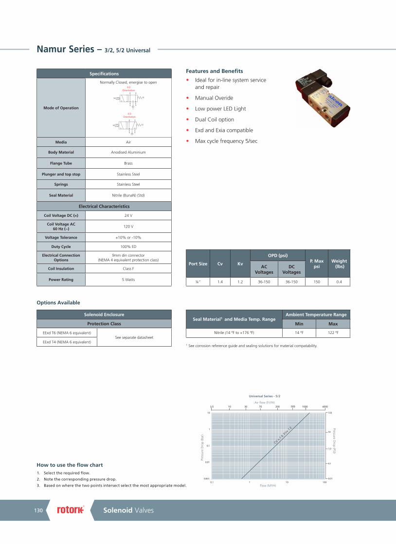
A4US
US
A4
US A4
US
A4
A4 US
US
A4
US
A4
A4 US
Solenoid Valves130
Namur Series – 3/2, 5/2 Universal
Features and Benefits
• Ideal for in-line system service and repair
• Manual Overide
• Low power LED Light
• Dual Coil option
• Exd and Exia compatible
• Max cycle frequency 5/sec
Specifications
Mode of Operation
Normally Closed, energise to open
5/2Orientation
3/2Orientation
4 2
5 3
14 12
4 2
5 3
1
14 12
Media Air
Body Material Anodised Aluminium
Flange Tube Brass
Plunger and top stop Stainless Steel
Springs Stainless Steel
Seal Material Nitrile (BunaN) (Std)
Electrical Characteristics
Coil Voltage DC (=) 24 V
Coil Voltage AC 60 Hz (~)
120 V
Voltage Tolerance +10% or -10%
Duty Cycle 100% ED
Electrical Connection Options
9mm din connector (NEMA 4 equivalent protection class)
Coil Insulation Class F
Power Rating 5 Watts
Port Size Cv Kv
OPD (psi)P. Max
psiWeight
(lbs)AC Voltages
DC Voltages
¼” 1.4 1.2 36-150 36-150 150 0.4
Options Available
Solenoid Enclosure
Protection Class
EExd T6 (NEMA 6 equivalent)See separate datasheet
EExd T4 (NEMA 6 equivalent)
1. Select the required flow.
2. Note the corresponding pressure drop.
3. Based on where the two points intersect select the most appropriate model.
How to use the flow chart
0.001
0.01
0.1
1
10
0010111.0
3.5 10 30 70 200 500 1000 4000
0.01
0.1
1.0
10
150
Pressure Drop (PSI)
CV = 1.4,
KV= 1.2
Pres
sure
Dro
p (B
ar)
Universal Series - 5/2
Air flow (Ft³/H)
Flow (M³/H)
Seal Material1 and Media Temp. RangeAmbient Temperature Range
Min Max
Nitrile (14 ºF to +176 ºF) 14 ºF 122 ºF
1 See corrosion reference guide and sealing solutions for material compatability.

A4US
US
A4
US A4
US
A4
A4 US
US
A4
US
A4
A4 US
Keeping the World Flowing 131
Style
1 Standard
Namur Series – 3/2, 5/2 Universal
Product coding example:
65B32Z3A1-1QY18: Namur, IP65 (NEMA 4 equivalent), 1/4” NPT, manual override, Aluminium body, Nitrile seals, 120 V / 60 Hz, electrical connection 9 mm DIN.
Main Valve Assembly
Size
B 1/4”
Connection Type
3 NPT
Operation
2Manual
Override
Body Material
3 Aluminium
Seals
A Nitrile
Preferred Valve Mounting Options
S7 enclosure protection class IP65 (NEMA 4 equivalent)
External material: Nylon
Electrical connection: DIN Plug to ISO 4400
Winding: Insulation Class F
Conforms to IP65 when correct plug seal gasket is fitted.
Solenoid enclosures
Dimensions given in inches
Orifice (mm)
Z Default
65 B 3 2 Z 3 A 1 -
Coil options
Voltage / Frequency
QY120 V / 60 Hz
R1 24 VDC
Electrical Connection
1Din plug
9mm
1 •• 1 8
Enclosure
1
Weather Proof IP65
(NEMA 4)
Approval
81 Non UL
Model
65 Namur
15/16"
1 37
/64"
1/4” NPT for inlet pilot supply pressure
Discs shown in 3/2
5 1/4"
Manual override
2 - off 1/4” NPT exhaust connections 2 - off 5/8" x 5/64"
‘O’ rings to seal on Namur interface
Discs shown in 5/21 1 /1
6"
1 17
/64"
1 Not needed for DC option.
Coding chart

A4US
US
A4
US A4
US
A4
A4 US
US
A4
US
A4
A4 US
Solenoid Valves132
U21 Series Ex – 2/2 Normally Closed
Features and Benefits
• Compact valve design
• Zero pressure rated
• Wide range of available orifices
• Choice of valve body material and seals
• Choice of electrical connections
• ATEX approved
• Response time 5-25 ms
• Tested in accordance with BS-EN 12266-1
Specifications
Mode of Operation
Normally Closed, energise to open
Out (2)
In (1)
Maximum Viscosity 115 SSU
Body Material Brass or Stainless Steel option
Flange Tube Stainless Steel
Plunger and top stop Stainless Steel
Springs Stainless Steel
Seal Material Nitrile (BunaN) (Std) other options available
Connection Type NPT
Shading Ring Copper (std), Silver (stainless steel option)
Electrical Characteristics
Coil Voltage DC (=) 12 V, 24 V
Coil Voltage AC 60 Hz (~)
24 V, 120 V
Voltage Tolerance +10% or -10%
Duty Cycle 100% ED
Protection Class (Exd)
II 2 G Ex d IIC T4 Tamb (-58 °F to +158 °F) (NEMA 6 equivalent)
II 2 G Ex d IIC T6 Tamb (-58 °F to +104 °F) (NEMA 6 equivalent)
Class 1 Zone 1
Groups IIA, IIB, IIC gases
Electrical Connection (Exd)
1/2” NPT Port (Std)
Coil Insulation Class H
Power Rating 14.5 Watts
Port size
Cv Kv
OPD (psi)P. Max
psiOrifice (mm)
Protection Class
Weight (lbs)
excluding solenoid
AC Voltages
DC Voltages
¼” 0.12 0.10 0-675 0-310
675
1.6 Exd T6
0.8
¼” 0.24 0.21 0-300 0-140 2.4 Exd T6
¼” 0.35 0.30 0-225 0-65 3.0 Exd T6
¼” 0.53 0.46 0-105 0-34 4.5 Exd T6
¼” 0.70 0.60 0-60 0-15 6.0 Exd T6
Options Available
Solenoid Enclosure
Protection Class Electrical Entry Enclosure Material
Exd T4 (NEMA 6 equivalent) 1/2” NPT conduit (std)
M20 X 1.5 conduit (option)
Aluminium (Std) Stainless Steel
optionalExd T6 (NEMA 6 equivalent)
Main valve body options
Stainless Steel 316
Manual Override
Stainless Steel Tagging (consult factory for product code)
1 See corrosion reference guide and sealing solutions for material compatability.
1. Select the required flow.
2. Note the corresponding pressure drop.
3. Based on where the two points intersect select the most appropriate model.
How to use the flow chart
Pres
sure
Dro
p (B
ar) Pressure D
rop (PSI)
0.10.010.001
0.01
0.1
1
10
1 10 1000.01
0.1
1
20
0.4 1.0 4 603010 400 4000200 1000
150
1.6
& 1.
2 m
m o
rifice
3.0
mm
orifi
ce
2.4
mm
orifi
ce
6.0
mm
orifi
ce
4.5
mm
orifi
ce
Seal Material1 and Media Temp. Range
Ambient Temperature Range
Min Max (T6) Max (T4)
Nitrile (14 ºF to +176 ºF) 14 ºF 104 ºF 158 ºF
EPDM (-58 ºF to +248 ºF) -58 ºF 104 ºF 158 ºF
Viton (-4 ºF to +302 ºF) -4 ºF 104 ºF 158 ºF
PTFE (-328 ºF to +356 ºF) -58 ºF 104 ºF 158 ºF

A4US
US
A4
US A4
US
A4
A4 US
US
A4
US
A4
A4 US
Keeping the World Flowing 133
U21 Series Ex – 2/2 Normally Closed
360º
Coil Rotation
1/2" NPT (std) conduit entry35/64421/64"
Aluminium enclosure as standard
Exd
147/64"421
/64"
4 11
/16"
Preferred Valve Mounting Options
Dimensions given in inches
Solenoid enclosures
11B31E1A3-5H29G: 21 Series 1/4” NPT, Auto , 2.4 mm orifice, brass body, nitrile seals, Exd Aluminium housing 120 V / 60 Hz, 1/2” NPT electrical connection, T6 CSA approved.
Product coding example:
11 B 3 • • • • 3 -
Main Valve Assembly Coil options
Size
B 1/4”
Connection Type
3 NPT
Operation
1 AUTO
2 MANUAL OVERIDE
Orifice (mm)
C 1.6
E 2.4
F 3.0
H 4.5
J 6.0
Body Material
1 Brass
5316
Stainless Steel
Seals
A Nitrile
B EPDM
C VITON
E PTFE
Style
3 Exd
• •• • •
Enclosure
5Exd
Aluminium
6Exd
Stainless Steel
Voltage / Frequency
F1 24 VDC
F4 12 VDC
H1 24 V / 60 Hz
H2 120 V / 60 Hz
Electrical connection
5 M20x1.5
9 1/2”NPT
T Rating
9 Atex T6
949 Atex T4
GAtex T6 (CSA)
IAtex T4 (CSA)
Exd S4 type enclosure
Power consumption: Holding 19 VA, 12 V to 230 V 50 / 60 Hz. 14.5 W, 12 V to 212 VDC
External material: Powder coated aluminium or 316 st.st. enclosure with st.st. nameplate
Electrical entry: M20 x 1.5 or 1/2” NPT conduit entry
Protection Class: II 2 G Exd IIC T6 for ambient temp -58 °F to +104 °F
Optional: II 2 G Exd IIC T4 for ambient temp -58 °F to +158 °F
Weight: 1.8 lbs Aluminium or 3.3 lbs - Stainless Steel
CSA approval
Alcon flame proof enclosures are suitable for the following areas / gases:
Zones 1 & 2
Class 1 Division 1
Class 1 Division 2
Groups: IIA, IIB, IIC gases
Model
11 U21 Series

A4US
US
A4
US A4
US
A4
A4 US
US
A4
US
A4
A4 US
Solenoid Valves134
U31/U33 Series Ex – 3/2 Normally Closed / Universal
Specifications
Mode of Operation
31 series 3/2 Normally Closed
33 series 3/2 Universal
Maximum Viscosity 115 SSU
Body Material Brass or Stainless Steel option
Flange Tube Stainless Steel
Plunger and top stop Stainless Steel
Springs Stainless Steel
Seal Material Nitrile (BunaN) (Std) other options available
Connection Type NPT
Shading Ring Copper (std), Silver (stainless steel option)
Electrical Characteristics
Coil Voltage DC (=) 12 V, 24 V
Coil Voltage AC 50 Hz (~)
24 V, 120 V
Voltage Tolerance +10% or -10%
Duty Cycle 100% ED
Protection Class (Exd)
II 2 G Ex d IIC T4 Tamb (-58 °F to + 158 °F) (NEMA 6 equivalent)
II 2 G Ex d IIC T6 Tamb (-58 °F to + 104 °F) (NEMA 6 equivalent)
Class 1 Zone 1
Groups IIA, IIB, IIC gases
Electrical Connection (Exd)
1/2” NPT Port (Std)
Coil Insulation Class H
Power Rating 14.5 Watts
Options Available
1
2
3
1
2
3
1 See corrosion reference guide and sealing solutions for material compatability.
Solenoid Enclosure
Protection Class Electrical Entry Enclosure Material
Exd T4 (NEMA 6 equivalent) 1/2” NPT conduit (std)
M20 X1.5 conduit (option)
Aluminium (Std) Stainless Steel
optionalExd T6 (NEMA 6 equivalent)
Main valve body options
Stainless Steel 316
Manual Override
Stainless Steel Tagging (consult factory for product code)
Port Size
Cv Kv
OPD (psi)P. Max
psiOrifice (mm)
Weight (lbs)
excluding solenoid
Desc.AC Voltages
DC Voltages
¼” 0.12 0.10 0-155 0-155
675
1.6
1.0
N/C
¼” 0.24 0.21 0-100 0-100 2.4 N/C
¼” 0.35 0.30 0-85 0-85 3.0 N/C
¼” 0.12 0.10 0-107 0-107 1.6 Universal
¼” 0.24 0.21 0-42 0-42 2.4 Universal
¼” 0.35 0.30 0-30 0-30 3.0 Universal
Features and Benefits
• Direct Acting
• Zero pressure rated
• Compact Valve Design
• Ideal for mixing, diverting and venting applications
• Choice of valve body material and seals
• Wide range of available orifices
• Response time 5-25 ms
• Tested in accordance with BS-EN 12266-1
1. Select the required flow.
2. Note the corresponding pressure drop.
3. Based on where the two points intersect select the most appropriate model.
How to use the flow chart
Pres
sure
Dro
p (B
ar) Pressure D
rop (PSI)
0.10.010.001
0.01
0.1
1
10
1 10 1000.01
0.1
1
20
0.4 1.0 4 603010 400 4000200 1000
150
1.6
mm
orifi
ce
3.0
mm
orifi
ce
2.4
mm
orifi
ce
Seal Material1 and Media Temp. Range
Ambient Temperature Range
Min Max (T6) Max (T4)
Nitrile (14 ºF to +176 ºF) 14 ºF 104 ºF 158 ºF
EPDM (-58 ºF to +248 ºF) -58 ºF 104 ºF 158 ºF
Viton (-4 ºF to +302 ºF) -4 ºF 104 ºF 158 ºF

A4US
US
A4
US A4
US
A4
A4 US
US
A4
US
A4
A4 US
Keeping the World Flowing 135
U31/U33 Series Ex – 3/2 Normally Closed / Universal
29B31E1A3-9H29G: 31 Series 1/4” NPT, Auto, 2.4 mm orifice, brass body, nitrile seals, Exd Aluminium housing, 120 V / 60Hz, 1/2”NPT electrical connection, T6 CSA approved.
Product coding example:
360º
Coil Rotation
Main Valve Assembly
Size
B 1/4”
Connection Type
3 NPT
Operation
1 AUTO
2 MANUAL OVERIDE
Orifice (mm)
C 1.6
E 2.4
F 3.0
Body Material
1 Brass
5316
Stainless Steel
Seals
A Nitrile
B EPDM
C VITON
Style
3 Exd
Dimensions given in inches
Preferred Valve Mounting Options
Exd S4 type enclosure
Power consumption: Holding 19 VA, 12 V to 230 V 50 / 60 Hz. 14.5 W, 12 V to 212 VDC
External material: Powder coated aluminium or 316 st.st. enclosure with st.st. nameplate
Electrical entry: M20 x 1.5 or 1/2” NPT conduit entry
Protection Class: II 2 G Exd IIC T6 for ambient temp -58 °F to +104 °F
Optional: II 2 G Exd IIC T4 for ambient temp -58 °F to +158 °F
Weight: 1.8 lbs Aluminium or 3.3 lbs - Stainless Steel
CSA approval
Alcon flame proof enclosures are suitable for the following areas / gases:
Zones 1 & 2
Class 1 Division 1
Class 1 Division 2
Groups: IIA, IIB, IIC gases
Solenoid enclosures
Coil options
Voltage / Frequency
F1 24 VDC
F4 12 VDC
H1 24 V / 60 Hz
H2120 V / 60 Hz
Electrical connection
5 M20x1.5
9 1/2”NPT
T Rating
9 Atex T6
949 Atex T4
GAtex T6 (CSA)
IAtex T4 (CSA)
• B 3 • • • • 3 -
Enclosure
93 way Exd
Aluminium
A3 way Exd Stainless
Steel
• •• • •
113/64"
211/6
4"
11 /32
147/64"
523/6
4"
137/6
4
421/64"219/32
Model
29 31 Series
32 33 Series

A4US
US
A4
US A4
US
A4
A4 US
US
A4
US
A4
A4 US
Solenoid Valves136
UACD Series Ex – 2/2 Normally Closed
Features and Benefits
• Robust Valve Design
• Diaphragm Operation
• Fully Ported orifices for high Kv
• Choice of valve body material seals
• ATEX Approved
• Response time up to 1” 15-60 ms
• Response time up to 2” 60-120 ms
• Tested in accordance with BS-EN 12266-1z
Specifications
Mode of Operation
Normally Closed, energise to openOut (2)
In (1)
Maximum Viscosity 115 SSU
3/8” - 1” Body Material (Std)
Brass (Std) or Stainless Steel option
11/4” - 2” Body Material (Std)
Bronze (Std)
Flange Tube Stainless Steel
Plunger and top stop Stainless Steel
Springs Stainless Steel
Seal Material Nitrile (BunaN) (Std) other options available
Connection Type NPT
Shading Ring Copper (std), Silver (stainless steel option)
Electrical Characteristics
Coil Voltage DC (=) 12 V, 24 V
Coil Voltage AC 60 Hz (~) 24 V, 120 V
Voltage Tolerance +10% or -10%
Duty Cycle 100% ED
Protection Class (Exd)
II 2 G Ex d IIC T4 Tamb (-58 °F to + 158 °F) (NEMA 6 equivalent)
II 2 G Ex d IIC T6 Tamb (-58 °F to + 104 °F) (NEMA 6 equivalent)
Class 1 Zone 1
Groups IIA, IIB, IIC gases
Electrical Connection (Exd)
1/2” NPT Port (Std)
Coil Insulation Class H
Power Rating 14.5 Watts
2 Pressure assisted to achieve a greater OPD. e.g. code 19G31Z2A3-5F19G.
Options Available
Port size
Cv Kv
OPD (psi)
P. Max psiOrifice (mm)
Weight (lbs)
excluding solenoid
AC Voltages
DC Voltages
3/8” 3.5 3.0 0-150 0-150
675
16.0 2
1/2” 4.9 4.2 0-150 0-150 16.0 2
3/4” 5.4 4.7 0-150 0-150 16.0 2
1” 8.2 7.0 0-150 0-150 20.0 4
1¼” 26.7 23 0-60 - 40.0 6.6
11/2” 26.7 23 0-60 - 40.0 6.6
2” 30.16 26 0-60 - 40.0 6.6
1¼”2 26.7 23 5-150 5-150 40.0 6.6
11/2”2 26.7 23 5-150 5-150 40.0 6.6
2”2 30.2 26 5-150 5-150 40.0 6.6
Solenoid Enclosure
Protection Class Electrical Entry Enclosure Material
Exd T4 (NEMA 6 equivalent) 1/2” NPT conduit (std)
M20 X1.5 conduit (option)
Aluminium (Std) Stainless Steel
optionalExd T6 (NEMA 6 equivalent)
Main Valve Body Options
Stainless Steel 316 (up to and including 1")
Manual Override
Oxygen Cleaning (consult factory for product code)
Stainless Steel Tagging (consult factory for product code)
1 See corrosion reference guide and sealing solutions for material compatability.
1. Select the required flow.
2. Note the corresponding pressure drop.
3. Based on where the two points intersect select the most appropriate model.
How to use the flow chart
Seal Material1 and Media Temp. Range
Ambient Temperature Range
Min Max (T6) Max (T4)
Nitrile (14 ºF to +176 ºF) 14 ºF 104 ºF 158 ºF
EPDM (-58 ºF to +248 ºF) -58 ºF 104 ºF 158 ºF
Viton (-4 ºF to +302 ºF) -4 ºF 104 ºF 158 ºF
ATEX
Pressure Drop
(PSI)
Water Flow (L/Min)
Pres
sure
Dro
p (B
ar)
Water Flow (GPM)2.2
1
0.110 100 1000
5 10 20 40 80 160
15
10
5
3
1.5
1¼"
& 1
1/2"
valv
e - 4
0.0
mm
orifi
ce
3/4"
valv
e - 1
6.0
mm
orifi
ce1"
val
ve -
20.0
mm
orifi
ce
1/2"
valv
e - 1
6.0
mm
orifi
ce
3 /8"
valv
e - 1
6.0
mm
orifi
ce
2" v
alve
- 40
.0 m
m o
rifice

A4US
US
A4
US A4
US
A4
A4 US
US
A4
US
A4
A4 US
Keeping the World Flowing 137
UACD Series Ex – 2/2 Normally Closed
Dimensions given in inches
Port size A B C D
3/8” - 3/4” 247/64" 4 27/32" 211/64" 533/64"
1” 33/8" 427/32" 211/64" 533/64"
1¼” - 2” 525/64" 525/32" 423/32" 73/32"
Preferred Valve Mounting Options
360º
Coil Rotation
Aluminium enclosure as standard1/2" NPT (std)
Exd
Dimensions
Solenoid enclosures
Product coding example:
17C31Z1B3-5H299G: UACD Series Exd 3/8”, NPT Auto, Brass body, EPDM seals, 120 V / 60Hz, Aluminium Exd enclosure, 1/2”NPT electrical connection, T6, CSA approval.
Main Valve Assembly Coil options
Valve Body Conn. Size
C 3/8”
D 1/2”
E 3/4”
F 1”
G 11/4”
H 11/2”
J 2”
Model
17 AC VOLTAGE
18 DC3 VOLTAGE
19
Pressure assisted option
11/4”to 2"
Operation
1 AUTO
2 MANUAL OVERIDE
Conn. Type
3 NPT
Seals
A Nitrile
B EPDM
C VITON
Style
3 Exd
Body Material
1
Brass (standard on valves up to and
including 1”
2
Bronze (standard on valves above 1”)
5
316 Stainless Steel (option available up to
and inc 1”)
•• • 3 • Z • • 3 -
Orifice (mm)
Z Default
3 1¼” to 2" '0' pressure rated options are not available in DC voltages.
Voltage / Frequency
F1 24 VDC
F4 12 VDC
H1 24 V / 60 Hz
H2120 V / 60 Hz
Electrical Connection
5 M20x1.5
9 1/2”NPT
Enclosure
5Exd
Aluminium
6Exd
Stainless Steel
Exd S4 type enclosure
Power consumption: Holding 19 VA, 12 V to 230 V 50 / 60 Hz. 14.5 W, 12 V to 212 VDC
External material: Powder coated aluminium or 316 st.st. enclosure with st.st. nameplate
Electrical entry: M20 x 1.5 or 1/2” NPT conduit entry
Protection Class: II 2 G Exd IIC T6 for ambient temp -58 °F to +104 °F
Optional: II 2 G Exd IIC T4 for ambient temp -58 °F to +158 °F
Weight: 1.8 lbs Aluminium or 3.3 lbs - Stainless Steel
CSA approval
Alcon flame proof enclosures are suitable for the following areas / gases:
Zones 1 & 2
Class 1 Division 1
Class 1 Division 2
Groups: IIA, IIB, IIC gases
35/64" 421/64"
27 /64
"
• •• • •
T Rating
9 Atex T6
949 Atex T4
GAtex T6 (CSA)
IAtex T4 (CSA)
Coding chart

A4US
US
A4
US A4
US
A4
A4 US
US
A4
US
A4
A4 US
Solenoid Valves138
ACDN Series Ex – 2/2 Normally Open
Features and Benefits
• Robust Valve Design
• Diaphragm Operation
• Fully Ported Orifices for high Kv
• Choice of valve body material seals
• Sizes 3/8” - 1” Advantica approved to BS EN 60730-2-8 for household use.
• Response time up to 1” 15-60 ms
• Response time up to 2” 60-120 ms
• Tested in accordance with BS-EN 12266-1
Specifications
Mode of Operation
Normally open, energise to close
Out (2)
In (1)
Maximum Viscosity 115 SSU
3/8” - 1” Body Material (Std)
Brass (Std) or Stainless Steel option
11/4” - 2” Body Material (Std)
Bronze (Std)
Flange Tube Stainless Steel
Plunger and top stop Stainless Steel
Springs Stainless Steel
Seal Material Nitrile (BunaN) (Std) other options available
Connection Type NPT
Shading Ring Copper (std), Silver (stainless steel option)
Electrical Characteristics
Coil Voltage DC (=) 12 V, 24 V
Coil Voltage AC 60 Hz (~)
24 V, 120 V
Voltage Tolerance +10% or -10%
Duty Cycle 100% ED
Protection Class (Exd)
II 2 G Ex d IIC T4 Tamb (-58 °F to + 158 °F) (NEMA 6 equivalent)
II 2 G Ex d IIC T6 Tamb (-58 °F to + 104 °F) (NEMA 6 equivalent)
Class 1 Zone 1
Groups IIA, IIB, IIC gases
Electrical Connection (Exd)
1/2” NPT Port (Std)
Coil Insulation Class H
Power Rating 14.5 Watts
1 See corrosion reference guide and sealing solutions for material compatability.
Options Available
Port Size
Cv Kv
OPD (psi)
P. Max psiOrifice (mm)
Weight (lbs)
excluding solenoid
AC Voltages
DC Voltages
3/8” 3.5 3.0 0-150 0-150
675
16.0 2
1/2” 4.9 4.2 0-150 0-150 16.0 2
3/4” 5.4 4.7 0-150 0-150 16.0 2
1” 8.2 7.0 0-150 0-150 20.0 4
1¼” 26.7 23 5-150 5-150 40.0 6.6
11/2” 26.7 23 5-150 5-150 40.0 6.6
2” 30.2 26 5-150 5-150 40.0 6.6
Main Valve Body Options
Stainless Steel 316 (up to and including 1")
Oxygen Cleaning (consult factory for product code)
Stainless Steel Tagging (consult factory for product code)
Solenoid Enclosure
Protection Class Electrical Entry Enclosure Material
Exd T4 (NEMA 6 equivalent) 1/2” NPT conduit (std)
M20 X1.5 conduit (option)
Aluminium (Std) Stainless Steel
optionalExd T6 (NEMA 6 equivalent)
1. Select the required flow.
2. Note the corresponding pressure drop.
3. Based on where the two points intersect select the most appropriate model.
How to use the flow chart
Seal Material1 and Media Temp. Range
Ambient Temperature Range
Min Max (T6) Max (T4)
Nitrile (14 ºF to +176 ºF) 14 ºF 104 ºF 158 ºF
EPDM (-58 ºF to +248 ºF) -58 ºF 104 ºF 158 ºF
Viton (-4 ºF to +302 ºF) -4 ºF 104 ºF 158 ºF
Pressure Drop
(PSI)
Water Flow (L/Min)
Pres
sure
Dro
p (B
ar)
Water Flow (GPM)2.2
1
0.110 100 1000
5 10 20 40 80 160
15
10
5
3
1.5
1¼"
& 1
1/2"
valv
e - 4
0.0
mm
orifi
ce
2" v
alve
- 40
.0 m
m o
rifice
1" v
alve
- 20
.0 m
m o
rifice
3/4"
valv
e - 1
6.0
mm
orifi
ce
1/2"
valv
e - 1
6.0
mm
orifi
ce
3 /8"
valv
e - 1
6.0
mm
orifi
ce

A4US
US
A4
US A4
US
A4
A4 US
US
A4
US
A4
A4 US
Keeping the World Flowing 139
ACDN Series Ex – 2/2 Normally Open
Dimensions given in inches
Port size A B C D
3/8” - 3/4” 247/64" 427/32" 261/64" 533/64"
1” 247/64" 427/32" 261/64" 533/64"
1¼” - 2” 525/64" 41/16" 423/32" 73/32"
Preferred Valve Mounting Options
Dimensions
360º
Coil Rotation
Aluminium enclosure as standard1/2" NPT (std)
Exd
Solenoid enclosures
Product coding example:
56C31Z1A3-DH298: ACDNEXD 3/8” NPT, auto, brass body, nitrile seals, aluminium housing, 120 V / 60 Hz, 1/2” NPT electrical connection ExdT6.
Main Valve Assembly Coil options
Voltage / Frequency
F1 24 VDC
F4 12 VDC
H124 V / 60 Hz
H2120 V / 60 Hz
Electrical Connection
5M20 x
1.5
91/2” NPT
Valve Body Conn. Size
C 3/8”
D 1/2”
E 3/4”
F 1”
G 11/4”
H 11/2”
J 2”
Model
27ACDN
(11/4 and above)
56ACDN
(3/8"-1")
Operation
1 AUTO
Conn. Type
3 NPT
Seals
A Nitrile
B EPDM
C VITON
Style
3 Exd
Body Material
1
Brass (standard on valves up to and
including 1”)
2
Bronze (standard on valves above 1”)
5
316 Stainless Steel (option available up to
and inc 1”)
• • 3 1 Z • • 3 -
Orifice (mm)
Z Default
Enclosure
DN/O Exd
Aluminium
EN/O Exd Stainless
Steel
Exd S4 type enclosure
Power consumption: Holding 19 VA, 12 V to 230 V 50 / 60 Hz. 14.5 W, 12 V to 212 VDC
External material: Powder coated aluminium or 316 st.st. enclosure with st.st. nameplate
Electrical entry: M20 x 1.5 or 1/2” NPT conduit entry
Protection Class: II 2 G Exd IIC T6 for ambient temp -58 °F to +104 °F
Optional: II 2 G Exd IIC T4 for ambient temp -58 °F to +158 °F
Weight: 1.8 lbs Aluminium or 3.3 lbs - Stainless Steel
CSA approval
Alcon flame proof enclosures are suitable for the following areas / gases:
Zones 1 & 2
Class 1 Division 1
Class 1 Division 2
Groups: IIA, IIB, IIC gases
421/64"35/64"
27 /64
"
• •• • •
T Rating
9 Atex T6
949 Atex T4
GAtex T6 (CSA)
IAtex T4 (CSA)
Coding chart

A4US
US
A4
US A4
US
A4
A4 US
US
A4
US
A4
A4 US
Solenoid Valves140
UACP Series Ex – 2/2 Normally Closed
Features and Benefits
• Heavy duty valve design
• Piston Operation
• Wide temperature range capabilities
• Choice of valve body material seals
• ATEX approved.
• Response time up to 1” 40-100 ms
• Response time up to 2” 60-1000 ms
• Tested in accordance with BS-EN 12266-1
Specifications
Mode of Operation
Normally closed, energise to open
Maximum Viscosity 115 SSU
3/8” - 1” Body Material (Std)
Brass (Std) or Stainless Steel option
11/4” - 2” Body Material (Std)
Bronze (Std)
Flange Tube Stainless Steel
Plunger and top stop Stainless Steel
Springs Stainless Steel
Seal Material Nitrile (BunaN) (Std) other options available
Connection Type NPT
Shading Ring Copper (std), Silver (stainless steel option)
Electrical Characteristics
Coil Voltage DC (=) 12 V, 24 V
Coil Voltage AC 60 Hz (~)
24 V, 120 V
Voltage Tolerance +10% or -10%
Duty Cycle 100% ED
Protection Class (Exd)
II 2 G Ex d IIC T4 Tamb (-58 °F to + 158 °F) (NEMA 6 equivalent)
II 2 G Ex d IIC T6 Tamb (-58 °F to + 104°F) (NEMA 6 equivalent)
Class 1 Zone 1
Groups IIA, IIB, IIC gases
Electrical Connection (Exd)
1/2”NPT Port (Std)
Coil Insulation Class H
Power Rating 14.5 Watts
Out (2)
In (1)
Main Valve Body Options
Stainless Steel 316 (up to and including 1")
Oxygen Cleaning (consult factory for product code)
Stainless Steel Tagging (consult factory for product code)
Options Available
1 See corrosion reference guide and sealing solutions for material compatability.
Port Size
Cv Kv
OPD (psi)P. Max
psiOrifice (mm)
Weight (lbs)
excluding Solenoid
Protection ClassAC
Voltages DC
Voltages
1/2” 4.9 4.2 5-150 5-150
675
16.0 2.8 Exd T6
3/4” 6.3 5.4 5-125 5-125 16.0 2.8 Exd T6
1” 14.5 12.5 5-125 5-125 25.0 5.0 Exd T6
1¼” 20.9 18 5-125 5-125 30.0 6.8 Exd T6
11/2” 20.9 18 5-125 5-125 30.0 6.8 Exd T6
2” 24.4 21 5-125 5-125 32.0 11.5 Exd T6
Solenoid Enclosure
Protection Class Electrical Entry Enclosure Material
Exd T4 (NEMA 6 equivalent) 1/2” NPT conduit (std)
M20 X1.5 conduit (option)
Aluminium (Std) Stainless Steel
optionalExd T6 (NEMA 6 equivalent)
1. Select the required flow.
2. Note the corresponding pressure drop.
3. Based on where the two points intersect select the most appropriate model.
How to use the flow chart
Seal Material1 and Media Temp. Range
Ambient Temperature Range
Min Max (T6) Max (T4)
Nitrile (14 ºF to +176 ºF) 14 ºF 104 ºF 158 ºF
EPDM (-58 ºF to +248 ºF) -58 ºF 104 ºF 158 ºF
Viton (-4 ºF to +302 ºF) -4 ºF 104 ºF 158 ºF
Pressure Drop
(PSI)
Water Flow (L/Min)
Pres
sure
Dro
p (B
ar)
Water Flow (GPM)2.2
1
0.110 100 1000
5 10 20 40 80 160
15
10
5
3
1.5
1¼"
& 1
1/2"
valv
e - 3
0.0
mm
orifi
ce
1" v
alve
- 25
.0 m
m o
rifice
3/4"
valv
e - 1
6.0
mm
orifi
ce
1/2"
valv
e - 1
6.0
mm
orifi
ce
2" v
alve
- 32
.0 m
m o
rifice

A4US
US
A4
US A4
US
A4
A4 US
US
A4
US
A4
A4 US
Keeping the World Flowing 141
UACP Series Ex – 2/2 Normally Closed
Dimensions
Dimensions given in inches
Port size A B C D
3/4” 311/32" 555/64" 261/64" 61/2"
1” 311/32" 7 3/64" 261/64" 751/64"
1¼”- 11/2” 439/64" 631/32" 317/64" 959/64"
2” 53/4" 77/16" 41/16" 959/64"
Preferred Valve Mounting Options
360º
Coil Rotation
Exd
22D31Z1A3-5H29G: UACP EXD Series 1/2” NPT, Auto, Brass body, nitrile seals, 120 V / 60 Hz, 1/2” NPT electrical connection, T6, CSA approval.
Product coding example:
Main Valve Assembly
Connection Type
3 NPT
Operation
1 AUTO
Orifice (mm)
Z Default
Seals
A Nitrile
B EPDM
C VITON
Style
3 Exd
Solenoid enclosures
Coil options
Voltage / Frequency
F1 24 VDC
F4 12 VDC
H1 24 V / 60 Hz
H2120 V / 60 Hz
Electrical Connection
5 M20x1.5
9 1/2”NPT
T Rating
9 Atex T6
949 Atex T4
22 • 3 1 Z • • 3 -
Enclosure
5Exd
Aluminium
6Exd
Stainless Steel
Valve Body Conn. Size
D 1/2”
E 3/4”
F 1”
G 11/4”
H 11/2”
J 2”
Body Material
1
Brass (standard on valves up to and
including 1”)
2
Bronze (standard on valves above 1”)
5
316 Stainless Steel (option available up to
and inc 1”)
Exd S4 type enclosure
Power consumption: Holding 19 VA, 12 V to 230 V 50 / 60 Hz. 14.5 W, 12 V to 212 VDC
External material: Powder coated aluminium or 316 st.st. enclosure with st.st. nameplate
Electrical entry: M20 x 1.5 or 1/2” NPT conduit entry
Protection Class: II 2 G Exd IIC T6 for ambient temp -58 °F to +104 °F
Optional: II 2 G Exd IIC T4 for ambient temp -58 °F to +158 °F
Weight: 1.8 lbs Aluminium or 3.3 lbs - Stainless Steel
CSA approval
Alcon flame proof enclosures are suitable for the following areas / gases:
Zones 1 & 2
Class 1 Division 1
Class 1 Division 2
Groups: IIA, IIB, IIC gases
35/64" 421/64"219/32"
Model
22 UACP
• •• • •
T Rating
9 Atex T6
949 Atex T4
GAtex T6 (CSA)
IAtex T4 (CSA)
Coding chart

A4US
US
A4
US A4
US
A4
A4 US
US
A4
US
A4
A4 US
Solenoid Valves142
Namur Series Ex & Exia – 3/2, 5/2 Universal
Features and Benefits
• Ideal for in-line system service and repair
• Choice of valve body material seals
• Manual Overide
• Low power LED Light
• Dual Coil option
• Exd, Exia compatible
• CSA approval (for Exd only)
• Max cycle frequency 5/sec
Specifications
Mode of Operation
3/2 or 5/2
5/2Orientation
3/2Orientation
4 2
5 3
14 12
4 2
5 3
1
14 12
Media Air
Body Material Anodised Aluminium
Flange Tube Brass
Plunger and top stop Stainless Steel
Springs Stainless Steel
Seal Material Nitrile (BunaN) (Std)
Electrical Characteristics
Coil Voltage DC (=) 12 V, 24 V
Coil Voltage AC 60 Hz (~) 24 V, 120 V
Voltage Tolerance +10% or -10%
Duty Cycle 100% ED
Protection Class (Exd)
II 2 G Ex d IIC T4 Tamb (-58 °F to + 158 °F) (NEMA 6 equivalent)
II 2 G Ex d IIC T6 Tamb (-58 °F to + 104°F) (NEMA 6 equivalent)
Class 1 Zone 1
Groups IIA, IIB, IIC gases
Protection Class (Exia)Exia IIC T6 (-40 °F to + 122 °F)
(NEMA 4 equivalent)
Electrical Connection (Exd)
1/2”NPT Port (Std)
Electrical Connection (Exia)
PG9 via Din Plug connector
Coil Insulation (Exd) Class H
Coil Insulation (Exia) Class F
Power Rating (Exd) 5 Watts
Power Rating (Exia) 1.6 Watts
Port Size
Cv Kv
OPD (PSI)P. Max
BarProtection
Class
Weight (lbs)
excluding Solenoid
AC Voltages
DC Voltages
¼” 1.4 1.2 36-150 36-150 150 Exd 0.4
Options Available
Solenoid Enclosure
Protection Class Electrical Entry Enclosure Material
EExd T6 (NEMA 6 equivalent) 1/2” NPT conduit (std)
M20 X1.5 conduit (option)Aluminium
EExd T4 (NEMA 6 equivalent)
Exia 9 mm DIN connectorThermoset resin Weather
Proof (NEMA 4 equivalent)
1. Select the required flow.
2. Note the corresponding pressure drop.
3. Based on where the two points intersect select the most appropriate model.
How to use the flow chart
0.001
0.01
0.1
1
10
0010111.0
3.5 10 30 70 200 500 1000 4000
0.01
0.1
1.0
10
150
Pressure Drop (PSI)
CV= 1.4,
KV= 1.2
Pres
sure
Dro
p (B
ar)
Universal Series - 5/2
Air flow (Ft³/H)
Flow (M³/H)
Seal Material1 and Media Temp. Range
Ambient Temperature Range
Min Max (T6) Max (T4) Max (Exia)
Nitrile (14 ºF to +176 ºF) 14 ºF 104 ºF 158 ºF 122 ºF
1 See corrosion reference guide and sealing solutions for material compatability.

A4US
US
A4
US A4
US
A4
A4 US
US
A4
US
A4
A4 US
Keeping the World Flowing 143
Namur Series Ex & Exia – 3/2, 5/2 Universal
Solenoid enclosures
Intrinsically safe enclosure (ATEX approved)
External material: Thermoset resin
Electrical connection: PG9 via DIN plug connector Din 43650-A
Max power consumption: Exia 1.6 Watts DC.
Winding: Insulation Class F
Protection class: Exia IIC T6, ATEX approved for ambient temperatures -40 ºF to + 122 ºF
Main Valve Assembly Coil options
Voltage / Frequency
F1 24 VDC
F4 12 VDC
H124 V / 60 Hz
H2120 V / 60 Hz
Electrical Connection
9 1/2” NPT
9 •• 9 •
Size
B 1/4”
Operation
2Manual
Override
Conn. Type
3 NPT
Seals
A Nitrile
Style
3 Exd
Body Material
3 Aluminium
65 B 3 2 Z 3 A 3 -
Orifice (mm)
Z Default
Enclosure
9 Exd Aluminium
T Rating
9Atex T6
KAtex
T4
GATEX
T6 (CSA)
IATEX
T4 (CSA)
Product coding example:
65B32Z3A13-9H299: Namur Exd 1/4” NPT, manual override, Aluminium body, Nitrile seals 120 / 60 Hz 1/2” NPT electrical connection T6.
Exd S4 type enclosure
Power consumption: Holding 19 VA, 12 V to 230 V 50 / 60 Hz. 14.5 W, 12 V to 212 VDC
External material: Powder coated aluminium or 316 st.st. enclosure with st.st. nameplate
Electrical entry: 1/2” NPT conduit entry (standard)
Protection Class: II 2 G Exd IIC T6 for ambient temp -58 °F to +104 °F
Optional: II 2 G Exd IIC T4 for ambient temp -58 °F to +158 °F
Weight: 1.8 lbs Aluminium or 3.3 lbs - Stainless Steel
CSA approval
Alcon flame proof enclosures are suitable for the following areas / gases:
Zones 1 & 2
Class 1 Division 1
Class 1 Division 2
Groups: IIA, IIB, IIC gases
Model
65 Namur
Exd
A
35/64"
557/6
4"
Manual override
1/2" NPT (std) Cable Entry
Exhaust ports ¼”BSP or NPT
Inlet port ¼”BSP or NPT
31 /64
"
11/2"
13 /16
"
15/32" 57/64"
355/64"
57/64" 43/64"
23/6
4"11 /1
6"
M5
23 /64
"29 /
32"
137/6
4"
Alcon solenoid operator Exd IIC T6 - IP67 NEMA 6 Equivalent ATEX approved
Disc arrangement 3/2 mode
15/16" 15/64"
Disc arrangement 5/2 mode
2 ‘O’rings 5/8" x 5/64" to seal on Namur interface
For Exm and Exia dimensions consult customer services
For Exia option use product code 65B32Z3A5-1QJ1. For all other coding options see below:

A4US
US
A4
US A4
US
A4
A4 US
US
A4
US
A4
A4 US
Solenoid Valves144
ADV Series, Compressed Air – with Solenoid Valves
Specifications1
Function (single acting)
A
PPilot Operated
flow direction overseat 1 2
Maximum Viscosity Max. 21cST (3 °E)
Body Material (Std) Brass C37700 (UNS Designation)
Flange Stainless Steel AISI 303 (1.4305 EN 10088)
Tube Stainless Steel AISI 304
Plunger Stainless Steel AISI 430F (1.4106 EN 10088)
Top Stop Stainless Steel AISI 430F (1.4105 EN 10088)
Springs Stainless Steel 302
Seal Material (Std) FKM
Connection Type NPT
Shading Ring Copper
Electrical Characteristics
Coil Voltage DC (=)24 V
Coil Voltage AC 50 Hz (~)24 V, 110 V, 230 V
Coil Voltage AC 60 Hz (~)120 V, 240 V
Voltage Tolerance +10% to -15% (AC)
+10% to -5% (DC)
Duty Cycle 100% ED
Enclosure ClassificationNEMA type 4 (UL 50) and IP65 (EN 60529)
with plug and gasket correctly fitted *
Electrical Connection to EN 175301 - 803 - A (ex DIN 43650)
Coil Insulation Class 155 (F) to UL429 and to EN 60730-1
Power Rating
( Coils)
AC 15 VA (holding)
AC 30 VA (inrush)
DC 14 W
Seal Material3 and Media Temperature Range
Media
Ambient Temperature Range
Min Max
FKM 14 °F to 266 °F(-10 °C to +130 °C)
Water, oil, air 14 °F(-10 °C)
122 °F(+50 °C)
Features and Benefits
• Preassembled systems consisting of solenoid valve, timer and connector
• Application: time adjusted condensate discharge of tanks with compressed air, separators, mains drainage, dryers and filters
• Direct acting and pilot operated valve
• Adjustable to suit your system requirements
• Indoor / outdoor installations
• Reliable, long life
• Cost effective
• Visual indication of operation
• Manual override - test button
• Discharge time (timer ON): from 0.5 to 10 s
• Interval time (timer OFF): from 30 s to 45 minutes
Pipe Size
OPD psi (bar) Orifice inches(mm)
Valve Code
Conn. Code
Timer Code
Coil code
ADV Code2
AC Volt DC Volt
With Pilot Operated Solenoid Valves
¼1.5 - 300(0.1 - 20.7)
-13/32 (10.5)
D264DVUN 600 011- AT2000C02I 740R 888 109 00A
³/81.5 - 300(0.1 - 20.7)
-13/32 (10.5)
D265DVUN 600 011- AT2000C02I 740R 888 105 00A
1/21.5 - 300(0.1 - 20.7)
-13/32 (10.5)
D266DVUN 600 011- AT2000C02I 740R 888 107 00A
ADV Options2
Strainers, G parallel thread (ISO 228-1), CE coils, impregnated coils with additional protection by impregnation with Loctite® Resinol RTC for
humid environments
2 ADV code changes depending on the required options. Codes in the selectiontable refer to the listed combination of components only.
Options Available
3 See corrosion reference guide and sealing solutions for material compatability.
1 For more information about detailed solenoid valve and timer please refer toeach single datasheet.

A4US
US
A4
US A4
US
A4
A4 US
US
A4
US
A4
A4 US
Keeping the World Flowing 145
ADV Series, Compressed Air – with Solenoid Valves
Valve Series A B C Weight Lb (kg)
D264-/265-/266- 3.86 (98) 4.17 (106) 4.76 (121) -
Dimensions inches (mm)
Solenoid enclosures
Type 600 011- Plug
Rated Voltage (max.): 250 VAC / 300 DC
Nominal Current: 10A (rated) / 16A (max)
Wire cross-section: 0.0023 inch² max (1.5 mm² max)
Cable Entry: PG9 (0.24 to 0.31 inch / 6 to 8 mm)
Enclosure classification: Conforms to IP65 (according to EN 60529)
with supplied gasket
Insulation class: group C- VDE 0110
Housing colour: black
UL approved, file No: E205538
7--R Type Coil - Insulation class F
Encapsulation material: PET 815ER Rynite®
Electrical connection: DIN EN 175301-803 form A
Winding insulation: Class H (P180)
Enclosure classification: Conforms to NEMA type 4 (UL 50) and IP65 (according to
EN 60529) with plug and gasket correctly fitted*
UL approved, file No: E193928
* Plug and gasket not supplied as standard, must be ordered separately.

A4US
US
A4
US A4
US
A4
A4 US
US
A4
US
A4
A4 US
Solenoid Valves146
At2000, Analog Electronic Timer
Features and Benefits
• Ideal for: automatic drain valve, sampling valves, lubrication system, air dryers
• Black colour
• UL file number: E200580
Specifications
Operation Temperature 14 °F to 122 °F (-10°C to +50°C)
Timing Temperature Coefficient
± 0.005% - °C
Time ON from 0.5 to 10 seconds
Time OFF from 30 seconds to 45 minutes
Set/reset/test membrane key
Indicatorsgreen LED for 'power ON'
red LED for ‘valve open’
Manual Override test
Electrical Characteristics
Supply Voltage (AC/DC)from 120 V to 240 V - 50/60 Hz ( )
from 24 V to 240 V - 50/60 Hz (CE)
Switch Holding Voltage 400 V max.
Switch Capacity 1A
Inrush Current 10A for 10 ms
Absorbition 4 mA max.
Duty Cycle 100% ED
Switch Life 3 • 108
Repeat Accuracy ±1%
Enclosure ClassificationNEMA type 4 (UL 50) and IP65 (EN 60529)
with plug and gasket correctly fitted *
Circuit UL 94 V0
Notes
In case of DC supply, polarity should be reversed: left fast-on positive (+), right fast-on negative (-). Please refer to product instructions for use.
Supplied in single boxes with two squared gaskets and M3x50 fixing screw (see assembling scheme)
Assembling scheme
Valve Series A B C Weight Lb (kg)
AT2000C02I 1.73 (44) 3.03 (77) 0.79 (20) 0.17 (0.077)
Dimensions inches (mm)

A4US
US
A4
US A4
US
A4
A4 US
US
A4
US
A4
A4 US
Keeping the World Flowing 147
Customized Products
Rotork is constantly evolving and developing new products, enabling us to remain competitive in an ever changing market and keeping at the forefront of technological advances. For many years Rotork has operated in the most diverse industrial sectors and therefore acquired vast experience with a multitude of specialist applications. Our experience enables us to understand, design and manufacture to our customers’ specific requirements.
We can develop new customised solenoid valve solutions according to the customers’ technical requirements and needs, concentrating on increasing functionality, optimising space and reducing costs of existing systems.
Please find below some examples:
INDUSTRIAL AUTOMATION PACKAGING WITH VACUUM SYSTEMS FOR INDUSTRY
CAR AIR CONDITIONING REFILLER STERILIZERSCOMPRESSED AIR TREATMENT
FIREFIGHTING SYSTEMSCOOLING SYSTEM

A4US
US
A4
US A4
US
A4
A4 US
US
A4
US
A4
A4 US
Solenoid Valves148
Technical Information
The following points should be considered to ensure a correct choice of valve:
Connections and Nominal Diameters
Threaded connections are either "G"- inches (ISO 228) or metric. Nominal diameters (DN) are expressed in millimetres and correspond to the diameter of the valve's main orifice.
Performances (OPD)
Pressure values shown in this catalogue are the max values expressed in relative bar with no pressure at outlet.
For 3/2 way solenoid valves the pressure range can vary when used in other functions or systems.
The maximum pressure (PN) that the valve can withstand is tested to 1.5 times the maximum value of the operating pressure differential (OPD).
Pressure (units of measurement)
The SI unit of pressure is the pascal (Pa), defined as 1 newton of force per square metre (1 N/m2).
As Pa is such a small unit, the kPa (1 kilonewton/m2) or MPa (1 Meganewton/m2) tend to be more appropriate to fluid engineering.
However, the most popular metric unit used to measure the pressure in fluid engineering field is the bar, which is equal to 105 N/m2, and approximates to 1 atmosphere. This unit is used throughout this publication.
Other units often used include lb/in2 (psi), kg/cm2, atm in H2O (atmosphere) and mm Hg. Conversion factors are readily available from many sources.
Absolute pressure (bar a)
This is the pressure measured from the datum of a perfect vacuum: i.e. a perfect vacuum has a pressure of 0 bar a.
Gauge pressure (bar g)
This is the pressure measured from the datum of the atmospheric pressure. Although in reality the atmospheric pressure will depend upon the climate and the height above sea level, a generally accepted value of 1.013 bar a (1 atm) is often used. This is the average pressure exerted by the air of the earth's atmosphere at sea level.
Gauge pressure = Absolute pressure - Atmospheric pressure
Pressure above atmospheric will always yield a positive gauge pressure. Conversely a vacuum or negative pressure is the pressure below that of the atmosphere. A pressure of -1 bar g corresponds closely to a perfect vacuum.
Differential pressure
This is simply the difference between two pressures. When specifying a differential pressure, it is not necessary to use the suffixes 'g' or 'a' to denote either gauge pressure or absolute pressure respectively, as the pressure datum point becomes irrelevant. Therefore the difference between two
pressures will have the same value whether these pressures are measured in gauge pressure or absolute pressure, as long as the two pressures are measured from the same datum.
Flow
The flow is the quantity of fluid that passes through the valve's main orifice which has the nominal diameter (DN) shown in the tables.
The flow is given with a constant Kv value (according to VDI/VDE 2173) that shows how many cubic meters of water, at a temperature of 20 °C, flow through the valve in one hour with a pressure difference of one bar across the valve.
To determine the flow at higher pressures, multiply the Kv value by the square root of the differential pressure. Flow values shown in the selection tables are subject to a tolerance of ± 15%.
Viscosity
Viscosity of a fluid (liquid or gas) is its resistance to flow freely in a duct.
This phenomenon is also called internal friction and depends on existing cohesion forces among the fluid molecules. The viscosity of liquids decreases as the temperature rises; the viscosity of gases grows if the volume does not change.
According to the International System of Units (SI), the physical quantities are: force F in Newton N, distance h in meters m, area A in square meters m2, speed u in meters per second m/s, the unit of measurement of the dynamic viscosity is Pascal per second (Pa•s) or Newton multiplied by second per square meter (N•s/m2).
Dividing the dynamic viscosity of the liquid by its density, you can obtain the kinematic viscosity. Its unit of measurement is expressed in square meter per second (m2/s). Since the given numerical values are too small, the most common used unit is 10.000 times smaller: the stokes (stox) St,
1 St = 1•10-4 m2/s or 10.000 St = 1 m2/s
as well as the additional unit centistokes cSt
1 cSt = 1•10-2 St
Coil power supply
It is important that the exact voltage and frequency of the coil is used for the valve to operate correctly. Provided the coil is fitted correctly on the operator and that the armature is not obstructed, the valve can be operated for an indefinite time within the temperature limitations indicated. All solenoid valves have a copper shading ring to reduce vibrations caused by alternating currents. Remark: The same valve fitted with coils of different power may have different pressure ratings than standard combinations indicated in each datasheet in this catalogue.
Media and Ambient Temperatures
Temperature limits for the media in the datasheets and should be used as a guide to valve selection. Normally the maximum ambient temperature can reach +50 °C for

A4US
US
A4
US A4
US
A4
A4 US
US
A4
US
A4
A4 US
Keeping the World Flowing 149
solenoid valves with coils in class “F”, +70 °C for class “H”. For applications outside these limits please contact our Technical Department.
General purpose solenoid valves
Solenoid valves shown in this catalogue, either normally open or normally closed, are intended to control the flow of fluids and cannot be used as safety valves.
Valve Installation
To ensure proper valve function please observe following instructions:
Water hammer or fluid hammer
Water hammer (or, more generally, fluid hammer) is a pressure surge or wave resulting when a fluid (usually a liquid but sometimes also a gas) in motion is forced to stop or change direction suddenly (momentum change).
Water hammer commonly occurs when a valve is closed suddenly at an end of a pipeline system, and a pressure wave propagates in the pipe. It may also be known as hydraulic shock.
When using liquid fluids water-hammer can occur at pressure of 6 relative bar or higher.
This pressure wave can cause major problems, from noise and vibration to pipe collapse. It is possible to reduce the effects of the water hammer pulses with accumulators and other features.
Mitigating measures:
– Air vessels typically have an air cushion above the fluid level, which may be regulated or separated by a bladder. Sizes of air vessels may be up to hundreds of cubic meters on large pipelines. They come in many shapes, sizes and configurations. Such vessels often are called accumulators or expansion tanks.
– Water Hammer Arrestors are hydropneumatic devices similar to shock absorbers that can be installed between the water pipe and the machine to absorb the shock and stop the banging.
Safety
This product is not a safety device and must not be used as sole device to prevent the over-pressure of some parts of the plant or the containment of dangerous fluids.
Always connect the coil’s earth terminal to ground to ensure the safety of the user and installation. The coil provides the basic insulation only. Install the product in a protected place to prevent electric shocks.
The coil should not be energized if it is not fitted onto a valve or without a plunger inside the valve, as it would overheat and get damaged. Do not touch the energized coil: risk of high temperature.
Do not use the tubes for conveying fluid to ground electrical devices.
Before disconnecting or disassembling the valve, make sure that there is no pressure inside the tubing or the valve itself. Accidental shocks due to fall or collision may damage the operator and/or the integrity of the coil encapsulation thus causing malfunctions such as loss of insulation, seizure of the moving parts and overheating.
Installation
Check for the operating conditions on product label and on the technical documents.
Check for compatibility between medium and valve materials. In case of doubt, please contact the manufacturer.
Keep the valve operator in a vertical position, facing upwards. This prevents limescale or dirt particles in the operator tube which could restrict the armature or create excessive noise whilst operating.
Whilst tightening or unscrewing the valve must be held or revolved only and exclusively by the hexagon or the frame set (in order to avoid damage to its components such as coil, armature tube, etc.).
The recommended tightening torque of the coil nut is 0,5 Nm maximum, a higher torque may cause damage to the valve armature tube.
The recommended tightening torque of the connector screw is 0,5 Nm maximum, a higher torque may cause an excessive yield stress with consequent damages to the coil rivet and/or plastic encapsulation.
Connections
To ensure that the solenoid valve works properly, do not connect to pipework with an internal diameter less than the nominal diameter (DN) of the valve. Clean all pipework before connection to the solenoid valve: care should be taken to prevent foreign bodies – dirt or material chips – from entering the valve during the assembly phase.
Use suitable seal material on the valve threads. Where liquid sealants are used, it is important to prevent them from entering the valve and block the movement.
Flow Direction
Respect the direction of flow across the valve, shown with an arrow or by numbers on the valve body, depending on the model type.
Filtration
If the fluid contains dirt particles it is necessary to install a filter upstream of the solenoid valve. Dirt is the most frequent cause of malfunction.
Environment
Coils fitted with suitable connectors have a protection class of IP65. However, it is advisable not to use the solenoid valve outside or in very damp conditions without adequate protection. Provide sufficient ventilation for the solenoid valve. During continuous service the coil of the solenoid valve becomes hot and should not be touched.

A4US
US
A4
US A4
US
A4
A4 US
US
A4
US
A4
A4 US
Solenoid Valves150
Sealing Solutions
NBR (BunaN)
Trade Names:Chemigum Hycar (Zeo (Goodyear)n Chemical), Ny Syn (Copolymer), Paracril (Uniroyal), Krynac (Polysar), PerNitrilen (Mobay)
This is the most widely used O-Ring elastomer. It has excellent resistance to petroleum products. Excellent compression set, tear and abrasion resistance. Suitable for air, oil, water, acetylene, kerosene, lime solutions, liquefied petroleum gases and turpentine.
• NBR/ BunaN is Alcon’s preferred sealing solution unless otherwise stated.
• Please note NBR (BunaN) is not recommended for highly aromatic petroleum / gasoline’s or acids.
EPDM (EPR or EPDM) EPDM (EPR)
Excellent resistance to weathering and ozone, water and steam, with good performance in castor and some phosphate ester based fluids and poor on petroleum / gasoline. It’s low and high temperature capabilities are good, having excellent resistance to set with good resilience, this low compression set provides a suitable solution for steam sealing. EPDM is suitable for temperatures above the NBR range. Ethylene-propylene is generally suitable for most photographic solutions as well as numerous chemical solutions. EPDM has served to replace the formerly used butyl.
• Please note EPDM should NEVER be used in contact with mineral based fluids or DI ester based lubricants, due to excessive swell and deterioration. When lubrication is required silicone grease or fluids should be used.
FKM (FPM FLUORELASTOMER)
It has high temperature capabilities, excellent resistance to hydraulic oils, petrol and many other chemicals. FKM O-Rings are used in automobile and other mechanical devices requiring maximum resistance to elevated temperature and to many functional fluids. FKM is a fluorocarbon elastomer. Primarily developed for handling hydrocarbons such as jet fuels, gasoline’s, solvent, etc., which normally caused detrimental swelling to NBR. FKM has a high temperature range similar to ethylene propylene but is more resistant to “dry heat”. FKM has a rather wide range of chemical compatibility.
*PTFE / Teflon®
PTFE is a fluorocarbon resin known as a disc sealing material solution where all other synthetic materials have failed. Rulon is a form of Teflon® having fillers which have been added for improved mechanical properties. Teflon® with fillers are considered more of a plastic than a resilient-type material. They are virtually unattacked by any fluid. PTFE provides sealing solutions for cryogenic and steam applications.
*Teflon® is a registered trademark of Du-Pont. It must be noted that PTFE sealing will allow slight let-by.
Silicone
This elastomer provides high and low temperature solutions under certain conditions for numerous applications (it must be noted that silicone is not suitable for steam applications). It can handle hydrogen peroxide and some acid solutions. Silicone’s retention of properties at high temperatures is superior to other elastic materials.
It must be noted that Silicone has poor tensile strength, tear resistance and abrasion resistance.
Neoprene
Neoprene is commonly used for refrigeration systems sealing as an external seal. Suitable for alcohol, mild acids, water, air, ammonia, argon gas and other gases.
Sigodur (filled PTFE) & Ruby
Stiff materials particularly suitable for heavy duty applications.
KALREZ® SpectrumTM 6375
KALREZ® SpectrumTM 6375 is a compound specifically designed for the chemical process industry. This compound has excellent broad chemical resistance, good mechanical properties, and outstanding hot-air aging properties. Kalrez®6375 is well suited for use in mixed process streams because of its excellent resistance to acids, bases and amines. It is also recommended for use in hot water, steam, pure ethylene oxide and propylene oxide.

A4US
US
A4
US A4
US
A4
A4 US
US
A4
US
A4
A4 US
Keeping the World Flowing 151
Metals
Ag (silver)
Silver is a soft, malleable metal with a characteristic sheen. It has the highest thermal and electrical conductivity of all metals. Alcon provide shading coil material for stainless steel valves in silver.
AI (aluminium)
Derived from the Latin ALUMEN for ALUM (Potassium aluminium sulphate). A lightweight material that offers high strength and rigidity along with good corrosion resistance and heat dissipation. Alcon provide die-cast bodies, solenoid enclosures and shading coils made from aluminium.
Cu (copper)
Copper is an important engineering material since it is widely used in its pure state and also in alloys with other metals. In its pure state it is the most important material in the electrical industry. It has high electrical conductivity and corrosion resistance and is easy to fabricate. It has reasonable tensile strength, controllable annealing properties and general soldering and joining characteristics. Alcon provide as standard shading rings produced from Copper.
CU Sn (bronze)
Bronze alloys consist of copper and tin primarily and these can be known as "tin bronzes". Since phosphorus is usually added to these alloys as a deoxidising agent during casting, the tin bronzes are commercially known as "phosphor bronzes". These alloys possess desirable properties such as high strength, wear resistance, and good sea water resistance. Alcon provide bodies from bronze.
Cu Zu (brass)
Brass is probably the best known of the “yellow metals” and it is produced in a wide variety of forms with many different characteristics and attributes. It is a basic alloy of copper and zinc and it finds many engineering applications. Alcon provide forged bodies from brass this forging brass has a composition of 58% copper, 2% lead and 40% zinc.
Fe CrNi 300 Series Stainless Steel (18-8) Austenitic
303 Stainless Steel is essentially low-carbon steel to which chromium has been added. It is the addition of chromium, in amounts of 18%, that adds strength and gives stainless steel its unique 'stainless', corrosion-resisting properties. The corrosion resistance, as well as other useful properties of the steel, is enhanced by the addition of other elements such as 8% nickel. Alcon provide flange tubes, bodies & springs in 300 series stainless steel.
316 Stainless Steel
316 Stainless Steel is essentially low-carbon steel to which chromium has been added. It is the addition of chromium, in amounts of 18%, that adds strength and gives stainless steel its unique ‘stainless’, corrosion-resisting properties. The corrosion resistance, as well as other useful properties of the steel, is enhanced by the addition of other elements such as 12% nickel. Alcon provide valve bodies flange tubes and coil enclosures in 316 series stainless steel.
430F & 430FR Magnetic Stainless Steel
Type 430F is a solenoid grade stainless steel that has the best magnetic properties and lowest residual magnetism. Type 430FR stainless, used for corrosive service for many years, also offers improved wear resistance, higher electrical resistivity and increased hardness. Alcon’s plunger and top stop materials are produced using the 430F series. Basic composition 18% chromium, remainder iron.

A4US
US
A4
US A4
US
A4
A4 US
US
A4
US
A4
A4 US
Solenoid Valves152
Modes of Operation
Valve Selection
A solenoid valve should be chosen whenever the following conditions are met:
Media without dirt particles
Moderate flow volumes
Average differential pressures
High speed in operation
Media with a viscosity not higher than 21 cST(3°E)
2/2 N/C Normally Closed Solenoid OperatedDirect Acting
Solenoid Pilot Operated
2 way, normally closed, energise to open, on/off operation (de-energise to close), with one inlet and one outlet connection. There are 2 types of valve operation – Direct Acting and Pilot Operated.
a) Direct Acting – The coil supplies all the power to open the valve and the valve will operate from zero pressure.
b) Pilot Operated – this can either be diaphragm or piston operated. These valves have a pilot hole which is opened/closed by the coil acting upon a plunger and diaphragm or piston used to control the main orifice. The operation relies on the media pressure difference between the inlet and outlet and a minimum operating pressure is required to operate these valves unless stated as zero.
2/2 N/O Normally Open SolenoidDirect Acting
SolenoidPilot Operated
2 way, normally open, energise to close, de-energise to open, with one inlet and one outlet connection. Can be either direct acting or pilot operated.
3/2 N/C Normally Closed
Valve open when energised, closed when de-energised. This valve operates on the same principle as the 2/2 N/C version except the valve has 3 connections, 2 orifices, one permanently open, one permanently closed. The use of these are for operation of actuators for large valves where single cylinder spring return system is employed.
3/2 N/O Normally Open
Valve open when de-energised, closed when energised.
3/2 UNI Universal
Valve may be used as normally closed, normally open or diversion/selector valve.
5/2
These valves are available in 2 forms;
a) Single Solenoid – 2 position, spool and sleeve type, which is based on an air pilot return mechanism. When de-energised, the valve allows one inlet and one outlet to be connected, exhausting the other inlet/outlet connection through an exhaust port. On energisation, the action reverses.
b) Dual Solenoid Valves – these spool and sleeve type solenoid valves are momentary contact type. When one coil is energised, one inlet is connected to one outlet, with the other inlet/outlet connection connected to an exhaust port, when the coil is de-energised and other coil energised, the action is reversed.
These valves are for use on double acting cylinder applications.

A4US
US
A4
US A4
US
A4
A4 US
US
A4
US
A4
A4 US
Keeping the World Flowing 153
Modes of Operation
Optional Features
Manual Override
Normally closed direct acting and pilot operated solenoid valves (only versions specified in each datasheet) can be supplied with a manual override which allows the valve to be opened independently of electrical current.
Waterhammer Control
Pilot operated solenoid valves (only versions specified in each datasheet) can be supplied with a system that regulates the closing speed of the diaphragm in order to control waterhammer.
The seal closing speed is operated by the adjusting screw: by screwing it clockwise (in the “+” direction) when using liquid, the valve will close slower reducing any waterhammer effect that may occur in the solenoid valve and the upstream pipes.
In the case of larger valves (1¼”, 11/2” and 2”), please adjust the anti-waterhammer screw to ensure that that valve closes as slowly as possible in order to avoid causing any damage that may affect the functioning of the equipment and valve due to the waterhammer effect.
2/2 N/C Normally Closed Pneumatic
2 way, normally closed, pressurise to open, de-pressurise to close with the aid of a return spring, having one inlet and one outlet connection. Can be direct acting air operated against a return spring. Note: These valves are operated via a 3 way solenoid valve which is always required.
2/2 N/O Normally Open Pneumatic
2 way, normally open, pressurise to close, de-pressurise to open with the aid of a return spring, having one inlet and one outlet connection. Can be direct acting air operated against a return spring. Note: These valves are operated via a 3 way solenoid valve which is always required
2/2 N/C Normally Closed Motorised m
2 way, normally closed, energise to open – (slow opening) de-energise to close – (quick closing) with one inlet and one outlet connection. Motor driven against a return spring.
2/2 N/O Normally Open Motorised m
2 way, normally open, energise to close – (slow closing) de-energise to open – (quick opening).
2/2 N/C Normally Closed Manual Reset (Solenoid)
These valves operate on the same principle as 2/2 N.C direct acting version except – once the coil is energised the valve will not open until manually opened by either a lever or push reset device.
2/2 N/C Normally Closed Manual Reset (Motorised) m
The operation is similar to 2/2 N/C Normally Closed Manual Reset (Solenoid) except, once the motor is energised the valve will not open till a manual reset/relay button is operated, either remote or integral to the actuator. General use is for both manual reset or safety systems where knowledge of an electrical failure is required.

A4US
US
A4
US A4
US
A4
A4 US
US
A4
US
A4
A4 US
Solenoid Valves154
Scheme of Components of Solenoid Valves
Electrical connection
Coil
Operator seal
Pilot orifice
Manual override
Nut, washer, label
Top Stop
Tube
Flange
Shading ring }= OPERATOR
Diaphragm spring
Plunger
Diaphragm(main seal)
Diaphragm speed control
Body
Cover
P1 (Inlet)
P2 (Outlet)
Mainorifice

A4US
US
A4
US A4
US
A4
A4 US
US
A4
US
A4
A4 US
Keeping the World Flowing 155
Din Plug Connectors
Features
• Dust and splash proof protected (IEC60529-IP65)
• Impact resistant plastic housing.
• Easy to install cable harness.
• Optional integrated electronic circuit, optional indicator LED with or without rectifiers etc.
• Retained central fixing screw.
• Special versions on request.
2
6
1
7
5
4
3
1. Terminal Block
2. Housing
3. Grommet
4. Washer
5. Strain relief nut
6. Central fixing screw
7. Gasket

A4US
US
A4
US A4
US
A4
A4 US
US
A4
US
A4
A4 US
Solenoid Valves156
Copper Winding Temperature Classification
Insulation Systems* Temperature Classification
Class A Class 105 105 °C 221 °F
Class E** Class 120 120 °C 248 °F
Class B Class 130 130 °C 266 °F
Class F Class 155 155 °C 311 °F
Class H Class 180 180 °C 356 °F
Class N Class 200 200 °C 392 °F
Insulation systems are arranged in order of their insulation level and classified by a letter symbol or by a numerical value.
The numerical value relates to the temperature classification of the insulation system.
The temperature classification indicates the maximum (hotspot) temperature at which the insulation system can be operated for normal expected service life.
In general, all materials used in a given insulation system should be rated for temperatures equal to, or exceeding, the temperature classification of the system.
* IEEE Std.117.
** Used in European equipment.
GROUP
GENERAL TOLERANCES
CHECKED
TRACED
SCALE
DATE
REPLACESSheet
DRW N°
MATERIAL WEIGHT ( g )FINISHING/TREATMENT
ANGLELENGTHPART N°
ROUGHNESSDESCRIPTION ( )Ref. Modifications P.M. Date Signature
BOBINA SERIE 7
bob_S72:1
13/02/1996
Forno M
Fioretti
80000700A1 / 1
± 30'± 1/2 IT13 UNI6387

A4US
US
A4
US A4
US
A4
A4 US
US
A4
US
A4
A4 US
Keeping the World Flowing 157
Series 2
Series 7
Features and Benefits
• UL approved coils recognized component, file number E193928
• Coils are designed for continuous duty in conformity to the EN 60730 safety standards.
• All coils are encapsulated in a self-extinguishing synthetic material and offer high mechanical protection and excellent thermal dissipation
• Fully interchangeable on all solenoid valves
• Reduced stock
Specifications
Electrical Connection fast on connection 0.25x0.03 inches (6,3x0,8 mm)
Protection ClassNEMA type 4 (UL 50) and IP65 (according to
EN60529) - with plug and gasket correctly fitted
Operation Continuous (ED 100%)
Voltage ToleranceAC +10% to -15%
DC +10% to -5%
Insulation Class according to EN 60730-11
1 See the below table.
Coils Options
Impregnated coils for humid environments
Custom voltages and low power consumption, please consult supplier for more details
Options Available
CoilCode
Serie VoltagesPower Insulation
Class
AmbientTemperature Range
MediaTemperature Range2
holding inrush min. max. min. max.
2150
Serie 2
Standard
12 VDC 7 W -
155 (F)14 °F
(-10 °C)
122 °F
(+50 °C)
14 °F
(-10 °C)
266 °F
(+130 °C)
2250 24 VDC 7 W -
2750 230 VDC 7 W -
2200 24 V / 50/60 Hz 10 VA 16 VA
2300 48 V / 50/60 Hz 10 VA 16 VA
2400 110 V / 50 Hz - 120 V / 60 Hz 10 VA 16 VA
2600 200 V / 50 Hz - 220 V / 60 Hz 10 VA 16 VA
2700 230V / 50 Hz - 240 V / 60 Hz 10 VA 16 VA
225R
Serie 2
UL approved
24 VDC 6 W -
155 (F)14 °F
(-10 °C)
140 °F
(+60°C)
14 °F
(-10 °C)
266 °F
(+130 °C)
220R 24 V / 50 Hz 9 VA 14 VA
240R 110 V / 50 Hz - 120 V / 60 Hz 9 VA 14 VA
270R 230 V / 50 Hz - 240 V / 60 Hz 9 VA 14 VA
21V1 Serie 2
High power
12 VDC 10 W -180 (H)
14 °F
(-10 °C)
158 °F
(+70°C)
14 °F
(-10 °C)
266 °F
(+130 °C)22V1 24 VDC 10 W -
7150
Serie 7
Standard
12 VDC 14 W -
155 (F)14 °F
(-10 °C)
122 °F
(+50 °C)
14 °F
(-10 °C)
266 °F
(+130 °C)
7250 24 VDC 14 W -
7750 230 VDC 14 W -
7200 24 V / 50/60 Hz 18 VA 36 VA
7300 48 V / 50/60 Hz 18 VA 36 VA
7400 110 V / 50 Hz - 120 V / 60 Hz 18 VA 36 VA
7600 200 V / 50 Hz - 220 V / 60 Hz 18 VA 36 VA
7700 230 V / 50 Hz - 240 V / 60 Hz 18 VA 36 VA
725R
Serie 7
UL approved
24 VDC 10 W -
155 (F)14 °F
(-10 °C)
140 °F
(+60°C)
14 °F
(-10 °C)
266 °F
(+130 °C)
720R 24 V / 50 Hz 15 VA 30 VA
740R 110 V / 50 Hz - 120 V / 60 Hz 15 VA 30 VA
770R 230 V / 50 Hz - 240 V / 60 Hz 15 VA 30 VA
7251
Serie 7
Class H
24 VDC 14 W -
180 (H)14 °F
(-10 °C)
158 °F
(+70°C)
14 °F
(-10 °C)
266 °F
(+130 °C)
7201 24 V / 50/60 Hz 18 VA 36 VA
7401 110 V / 50 Hz - 120 V / 60 Hz 18 VA 36 VA
7701 230 V / 50Hz - 240 V / 60 Hz 18 VA 36 VA
71Z1
Serie 7
High power
12 VDC 22 W -
180 (H)14 °F
(-10 °C)
158 °F
(+70°C)
14 °F
(-10 °C)
266 °F
(+130 °C)
72Z1 24 VDC 22 W -
72K1 24 V / 50/60 Hz 25 VA 50 VA
74K1 110 V / 50 Hz - 120 V / 60 Hz 25 VA 50 VA
77K1 230 V / 50 Hz - 240 V / 60 Hz 25 VA 50 VA
Solenoid Enclosures (Safe Area), 2 & 7 Coils Series
2 Some valve configurations allow a max. fluid temperature up to 356 °F (180 °C), please check valve datasheets.

A4US
US
A4
US A4
US
A4
A4 US
US
A4
US
A4
A4 US
Solenoid Valves158
Solenoid Enclosures (Safe Area), 2 & 7 Coils Series
Series 2:Series 7:
Dimensions inches (mm)
Coils Series A B C D Weight Lb (kg)
Series 2 0.77 (19.5) 0.44 (11.2) 0.88 (22.3) 1.33 (33.7) 0.132 (0.060)
Series 7 0.98 (25) 0.63 (16) 1.26 (32) 1.63 (41.4) 0.321 (0.146)

A4US
US
A4
US A4
US
A4
A4 US
US
A4
US
A4
A4 US
Keeping the World Flowing 159
Solenoid Enclosures (Safe Area)
S4 Type Enclosure
Protection Class IP50External Material: Pressed steel Powder Coated
Electrical Entry: Conduit boss 20 mm or 1/2” NPT
Electrical Connection: Screwed terminals or 0.5 mm flying leads, or DIN connector for cryogenic applications
Winding insulation Class H
Optional enclosure for the following types: ACD, ACDN, GB.
S7 Type Enclosure
Protection Class IP65Material: Nylon
Electrical Connection: DIN Plug to ISO 4400
Standard Enclosure for Universal Namur Valves
Winding insulation Class F
This enclosure conforms to IP65 when correct plug seal gasket is fitted as supplied.
Type : S4, S7

A4US
US
A4
US A4
US
A4
A4 US
US
A4
US
A4
A4 US
Solenoid Valves160
Solenoid Enclosures (Hazardous Area)
Intrinsically Safe Enclosures (ATEX approved)
Complies with EN60079-0 and EN60079-11
Protection Class: Exia IIC T6, ATEX approved for ambient temperatures -40 ºC to + 50 ºC
Maximum valve media temperature of 70 ºC
Certificate No: PTB 02 ATEX 2154
Weatherproof to IP65
Technical Specification
Winding insulation: Class F
Rated Voltage: 24 VDC with typical 300 ohm zener barrier
Max Power Exia 1.6 watts DC Consumption:
Material: Thermoset resin
Electrical Entry: PG9 via Din Plug Connector Din 43650-A
Applicable to the following types: UNIVERSAL NAMUR
Explosion-proof / Weatherproof
Enclosure S4 Type Exd ATEX or IECEx / CSA / cCSAus approved.
Intended for use in potentially explosive atmospheres Directive 2014/34/EU.
Compliance with essential health and safety requirements EN60529 (IP67), EN60079-1 and EN60079-0
Features
• Special purpose solenoid valves are used for controlling gases or liquids where a potentially explosive gas/air mixture is present in the atmosphere for long periods or likely to occur in normal operation
• Alcon flameproof enclosures are suitable for hazardous areas Zone 1 and Zone 2, for the control of Group IIA, IIB, IIC gases.
Application
• Valves configured for Hazardous Areas
• User to consult all applicable codes, such as N.E.C., EU directive 99/92/EC, for definitions, performance and safety requirements associated with Hazardous Area Classification, Apparatus Group, Zones, Division and Temperature Classification
Protection Class: II 2 G Exd IIC T6 for ambient temperatures -50 ºC to +40 ºC
Optional: II 2 G Exd IIC T4 for ambient temperatures -50 ºC to +70 ºC
Certificate No: Sira 03ATEX1319 (ATEX)
IECEx CSA 07.0002
1676463 (CSA cCSAus)
Weatherproof to IP67
Technical Specification
Power Consumption: Holding – 19 VA, 12 V to 230 V 50 / 60 Hz. 14.5 W 12 V to 212 VDC
Material: Powder coated Aluminium or 316 St. St enclosure with St. St nameplate
Electrical Entry: M20 x 1.5 or 1/2”NPT Conduit Entry
Applicable to the following types: ACD, ACP, GB, NAMUR

A4US
US
A4
US A4
US
A4
A4 US
US
A4
US
A4
A4 US
Keeping the World Flowing 161
Protection Class, IP Ratings & Hazardous Areas
Enclosure Protection - Non Hazardous locations, Comparison of American Nema classification & European CENELEC IP classification
Nema type & relevant tests Description Equivalent degree of protection
1 General purpose - indoor IP30
2 Drip proof - indoor IP32
3 Dust and rain tight - outdoor IP54
3R Rain proof - outdoor IP54
4 Water tight and dust tight - indoor and outdoor IP65
4XWater tight, dust tight and corrosion resistant - indoor and
outdoorIP65
6 Submersible, water tight and dust tight - indoor and outdoor IP67
12 Industrial use, dust tight and drip proof - indoor IP52
13 Oil tight and dust tight - indoor IP55
IP No.First number - protection again
solids
Second number - protection against
liquids
0 No protection No protection
1Protected against solid objects
over 50 mm Ø
Protected against vertically falling drops of
water
2Protected against solid objects
over 12 mm Ø
Protected against direct sprays up to 15 °From
vertical
3Protected against solid objects
over 2.5 mm Ø
Protected against direct sprays up to 60 °From
vertical
4Protected against solid objects
over 1 mm Ø
Protected against direct sprays from all directions limited ingress permitted.
5Protected against dust - limited ingress permitted
Protected against low pressure jets from all
directions limited ingress permitted
6 Totally protected against dustProtected against strong jets from all directions
limited ingress permitted
7Protected against effects of immersion from 15 cm
- 1m
8Protected against long periods of immersion
under pressure
IEC 79-8 & CENELEC Amercian NEC
ClassMax. surface
tempClass
Max. surface temp
T1 842 °F (450 °C) T1 842 °F (450 °C)
T2 572 °F (300 °C)
T2
T2A
T2B
T2C
T2D
572 °F (300 °C)
536 °F (280 °C)
500 °F (260 °C)
446 °F (230 °C)
419 °F (215 °C)
T3 392 °F (200 °C)
T3
T3B
T3C
392 °F (200 °C)
329 °F (165 °C)
320 °F (160 °C)
T4 275 °F (135 °C)T4
T4A
275 °F (135 °C)
248 °F (120 °C)
T5 212 °F (100 °C) T5 212 °F (100 °C)
T6 185 °F (85 °C) T6 185 °F (85 °C)
International Standards - Temperature classification
Zones & divisions - Define the likelihood of the hazard being present in potentially explosive concentrations
UK / CENELEC / IEC USA & CANADA
Hazard continuously present (>1000 hrs / year) Zone 0Division 1
Hazard likely to be present: N.B. where the hazard is continuously present,
electrcial apparatus is avoided if possible. Hazard likely to be present Zone 1
Hazard unlikely to be present: typically only for short periods or under fault conditions (<10 Hrs/year)
Zone 2
Division 2
Hazard unlikely to be present - likely to be confined. An area adjacent to a Division 1 area.
Fully defined in BS5345 and IEC 79-10 (Guideline figures)
Fully described in Article 500 of the National Electrical Code.

A4US
US
A4
US A4
US
A4
A4 US
US
A4
US
A4
A4 US
Solenoid Valves162
Conversions
Capacity & flow rate
m3/h l/s l/m m3/s (cumec) UK gpm US gpm ft3/s (cusec)Water
UK ton/h tonne/h
1 m3/h 1 0.278 16.66 0.000278 3.666 4.4 0.00981 0.982 1
1 l/s 3.6 1 60 0.001 13.2 15.83 0.00353 3.528 3.6
1 l/m 0.06 0.0167 1 1.66 x 10⁻⁵ 0.2199 0.264 0.000588 0.059 0.06
1 m3/s 3600 1000 60,000 1 13,200 15,800 35,315 3532 3600
1 UK gpm 0.272 0.0757 4.546 0.000757 1 1.2 0.002267 0.268 0.272
1 US gpm 0.227 0.0632 3.785 0.000063 0.833 1 0.00223 0.223 0.227
1 ft3/s 101.9 28.32 1698 0.0283 374 449 1 100 101.9
1 UK ton/h 1.02 0.283 17 0.000283 3.73 4.48 0.01 1 1.02
1 tonne/h 1.005 0.278 16.7 0.000278 3.666 4.41 0.0098 0.98 1
Multiply number of
by to obtain
Volumetric rate of flow
Litres per sec
Litres per minute
Cubic metres per hour
Cubic Ft per hour
Cubic Ft per min
Imperial Gallons per min
U.S. Gallons per min
U.S. Barrels per day
Litres per sec 1 60 3.6 127.1 21.19 13.2 15.85 543.4
Litres per min 0.1667 1 0.06 2.119 0.03532 0.22 0.2642 9.057
Cubic metres per hour 0.2778 16.67 1 35.31 0.5886 3.666 4.403 150.9
Cubic Feet per hour 0.007865 0.4719 0.02832 1 0.01667 0.1038 0.1247 4.275
Cubic Feet per min 0.4719 28.32 1.6999 60 1 6.229 7.481 256.5
Imperial Gallons per min 0.07577 4.546 0.2727 9.633 0.1606 1 1.201 41.17
U.S. Gallons per min 0.06309 3.785 0.2271 8.021 0.1337 0.8327 1 34.29
U.S. Barrels per day 0.00184 0.1104 0.0006624 0.2339 0.0003899 0.02428 0.02917 1
Multiply number of
by to obtain
Temperature
To convert from To Fahrenheit To Celcius To Kelvin
Fahrenheit (F) F (F-32) * 5/9 (F-32) * 5/9 + 273.15
Celcius (C) (C*9/5) + 32 C C + 273.16
Kelvin (K) (K - 273.15) * 9/5 + 32 K - 273.15 K
1 MGD = 189.4 m3/h 1 scfm = 1.699 Nm3/h
Pressure
barPsi
(lbf/in2)Cm water
(39.2 °F, 4 °C)Inch of water (39.2 °F, 4 °C)
Foot of water (39.2 °F, 4 °C)
Kilopascal (kPa)
Bar 1 14.503 77 1019.74 401.474 33.456 2 100
Psi (lbf/in2) 0.068 947 57 1 70.308 9 27.680 7 2.306 73 6.894 757
Cm water (39.2 °F, 4 °C) 0.000 980 638 0.014 223 0 1 0.393 701 0.032 808 4 0.098 063 8
Inch of water (39.2 °F, 4 °C) 0.002 490 82 0.036 123 3 2.54 1 0.083 333 4 0.249 082
Foot of water (39.2 °F, 4 °C) 0.029 889 8 0.433 515 30.48 12.021 3 1 2988 98
Kilopascal (kPa) 0.01 0.145 037 7 10.197 4 4.014 74 0.334 562 1
Multiply number of
by to obtain

A4US
US
A4
US A4
US
A4
A4 US
US
A4
US
A4
A4 US
Keeping the World Flowing 163
Corrosion Reference Guide
This chart is for general recommendation only. When ordering valves for corrosive duty application details are to be given, particularly media, % concentration, temperature and ambient temperature. For additional support please contact us.
Valve Body Seals Notes
Material Alum Brass Brz CI Stainless NBR EPDM FKM PTFE
Acetic Acid 10% NR NR NR NR • NR • NR • 1
Acetone • • • • • NR • NR •
Acetylene NR • • NR • NR • • • 1
Air • • • • • • • • •
Ammonia Gas Anhydrous 20% NR NR NR • • NR • NR •
Argon Gas • • • NR • NR • • •
Beer NR NR NR NR • • • • NR
Benzene • • • NR • NR NR • •
Bromine (Liquid) NR NR NR NR NR NR NR • NR 1
Butane • • • • • • NR • •
Carbon Dioxide (Gas) •. •. • • • • • • •
Carbon Dioxide (Liquid) NR NR NR NR • NR NR NR •
Carbon Tetrachloride (Dry) NR • • NR • NR NR • •
Carbonated Water NR NR NR NR • • • NR •
Caustic Soda 30% NR NR NR NR • NR • NR •
Chrome Acid 20% - 20C NR NR NR NR • NR NR • •
Chlorine Gas (Dry) NR NR NR NR NR NR NR • • 1
Chlorine Liquid NR NR NR NR NR NR NR • • 1
Chlorine in Water NR • • NR • • • NR • 2
Coke Oven Gas • NR NR • • • NR NR •
Coolant NR • • NR • • NR • •
Creosote • NR NR NR • NR NR • •
Crude Oil • NR NR NR • • NR • •
De-ionized Water NR NR NR NR • • • • •
De-mineralised Water NR NR NR NR • • • • •
Detergents NR • • NR • • • • •
Diesel Oil • • • . • • NR • •
Distilled Water NR • • NR • • • • •
Ethyl Alchohol NR • • NR • • • • •
Ethylene Glycol • • • NR • •. • • •
Ethylene Oxide NR NR NR NR • NR NR NR NR 1
Food Products NR NR NR NR • • NR • NR
Freon 12 NR • • • • NR NR NR •
Freon 22 NR NR NR NR • NR NR NR •
Freon Solvents NR • • NR • • NR NR •
Fuel Oil • • • NR • • NR • •
Gasoline NR • • NR • NR NR • •
Helium • • • NR • • • • •
Hydraulic Fluids NR • • NR • NR NR • •
Hydrochloric Acid NR NR NR NR NR NR NR NR • 1
Hydrogen Gas • • • • • • • • • 3
Hydrogen Sulphide (dry) NR NR NR NR • NR • • •
Jet Fuel • NR NR NR • • NR • •
Kerosene • • • • • • NR • •
Notes:1. Non-standard materials of construction are required.2. Chlorine must not exceed 5 parts per million.
3. We are required to provide industry standard degreasing, cleaning and individual packaging with appropriate label.
• = RecommendedNR = Not Recommended

A4US
US
A4
US A4
US
A4
A4 US
US
A4
US
A4
A4 US
Solenoid Valves164
Corrosion Reference Guide
This chart is for general recommendation only. When ordering valves for corrosive duty application details are to be given, particularly media, % concentration, temperature and ambient temperature. For additional support please contact us.
Valve Body Seals Notes
Material Alum Brass Brz CI Stainless NBR EPDM FKM PTFE
LPG • • • NR • • NR • •
Lubricating Oil • • • • • NR • • •
Methane Gas • • • • • • NR • •
Methyl Alcohol NR • • • • • • • •
Mineral Oil • • • • • • NR • •
Natural Gas • • • • • • • • •
Natural Gas Liquid NR • • NR • NR NR NR • 3
Nitric Acid 50% 20C NR NR NR NR • NR NR • •
Nitrogen gas • • • • • • • • •
Nitrogen Liquid NR • • NR • NR NR NR • 3
Nitrous Oxide NR NR NR NR • NR • NR •
Oxygen Gas NR • • NR • NR NR • • 3
Oxygen Liquid • • • NR • NR NR NR • 3
Paraffin • • • NR • • • • •
Perchlcrenthylene 20C NR • • NR • NR NR • •
Phosperic Acid 30% NR NR NR • NR NR • • • 1
Photographic solution NR NR NR NR NR NR NR NR • 1
Potable water NR • • NR • • • • •
Potassium Sulphate NR NR NR • • • • • •
Propane • • • NR • • NR • •
Salt Water NR NR • NR • • • • • 1
Sea Water NR NR • NR • • • • • 1
Soapy Water NR • • NR • • NR • •
Sodium Hydroxide 70% NR NR NR NR • NR • • •
Sodium Hypochorite 5% NR NR NR NR • NR • • •
Steam 0 - 50 psi NR • • NR • NR • NR •
Steam 0 - 125 psi NR • • NR • NR NR NR •
Steam Condensate NR • • NR • NR • NR •
Sulphur Dioxide NR NR NR NR • NR • NR •
Sulphuric Acid 40% NR NR NR NR NR • • • • 1
Sulphurous Acid 5% - 20C NR NR NR NR NR NR NR • • 1
Toluene • • • NR • NR NR NR •
Town Gas • • • • • • NR • •
Trichlorethylene (Dry) NR NR NR NR • NR NR • •
Turpentine • • • NR • • NR • •
Vegetable Oil NR NR NR NR • • NR • •
Vinegar NR NR NR NR • NR • NR • 1
Water (mains) NR • • • • • • • •
Water 80 - 120 °C NR • • NR • NR • • •
Water 120 - 150 °C NR • • NR • NR NR • •
Water 150 - 180 °C NR • • NR • NR NR NR •
Water boiler feed NR NR NR NR • • • NR •
Water/Glycol Solutions NR • • NR • NR • • •
White Spirit • • • • • NR NR • •
Notes:1. Non-standard materials of construction are required.2. Chlorine must not exceed 5 parts per million.
3. We are required to provide industry standard degreasing, cleaning and individual packaging with appropriate label.
• = RecommendedNR = Not Recommended

A4US
US
A4
US A4
US
A4
A4 US
US
A4
US
A4
A4 US
Keeping the World Flowing 165
Viscosity Reference Guide
Redwood 1 Redwood 11 Saybolt Universal Saybolt Fural Engler Kinematic
(Seconds) (Seconds) SSU (Seconds) (Seconds) (Degrees) (Centistrokes)
30 - - - 1.05 1.5
32 - 34 - 1.15 2.5
34 - 37 - 1.25 3.4
36 - 40 - 1.3 4.2
38 - 42 - 1.4 5
40 - 45 - 1.45 5.7
45 - 50 - 1.6 7.5
50 - 57 - 1.8 9.4
55 - 62 - 1.9 11
60 - 68 - 2.1 12.6
65 - 74 - 2.2 14.2
70 - 79 - 2.4 15.5
75 - 85 - 2.6 17
80 - 92 - 2.7 18.6
85 - 98 - 2.9 20
90 - 103 - 3 21.3
95 - 109 - 3.2 22.8
100 - 115 15 3.4 24.1
110 - 125 16 3.7 26.7
120 - 137 17 4 29.2
130 - 148 18 4.3 31.7
140 - 160 20 4.6 34.2
150 - 171 21 4.9 36.8
160 - 183 22 5.2 39
180 - 205 24 5.9 44
200 - 228 26 6.5 49
225 - 256 28 7.3 55
250 - 285 31 8.1 62
275 - 313 34 8.9 68
300 - 342 37 9.8 74
325 34 370 40 10.6 80
350 36 399 42 11.4 86
375 38 428 45 12.2 93
400 41 456 48 13 99
450 46 513 53 14.7 111
500 51 570 59 16.3 124
550 56 628 65 17.9 136
600 61 684 71 19.5 148
700 71 799 82 22.8 173
800 81 912 94 26.1 198
900 91 1025 105 29.3 222
1000 100 1142 117 32.6 247
1100 110 1257 128 35.9 272
1200 120 1368 140 39 296
1400 140 1599 163 46 346
1600 160 1825 186 52 395

A4US
US
A4
US A4
US
A4
A4 US
US
A4
US
A4
A4 US
Solenoid Valves166
Viscosity Reference Guide
Redwood 1 Redwood 11 Saybolt Universal Saybolt Fural Engler Kinematic
(Seconds) (Seconds) SSU (Seconds) (Seconds) (Degrees) (Centistrokes)
1800 180 2050 209 59 444
2000 200 2280 232 65 493
2200 220 2510 255 72 534
2400 240 2735 278 78 592
2600 260 2965 302 85 642
2800 280 3190 325 91 691
3000 300 3420 348 98 741
3500 350 3990 406 114 864
4000 400 4560 464 130 987
4500 450 5140 522 147 1112
5000 500 5700 580 163 1235
5500 550 6280 639 179 1359
6000 600 6840 696 195 1482
6500 650 7415 754 212 1605
7000 700 7990 814 228 1730
7500 750 8550 869 244 1850
8000 800 9120 928 261 1957

A4US
US
A4
US A4
US
A4
A4 US
US
A4
US
A4
A4 US
Keeping the World Flowing 167
Quality Standards
Certifications and approvals
The Ex mark signifies that a product complies with the ATEX Directive 94/9/EC (applicable up to 20th April 2016 but already implemented by Directive 2014/34/EU, effective from 18th April 2014).
The ATEX Directive sets the safety requirements of protection equipment and systems to be used in an environment with a potentially explosive atmosphere.
The Ex mark on a product enables its free movement within the European market (EEA).
The UL Listing mark on a product signifies that the product meets UL’s Standards for Safety. The UL Listing mark appears on products and components suitable for factory and field installation.
All of the products carrying a UL Listing mark are covered by UL’s Follow-up services program to verify that the products continue to be manufactured in compliance with UL’s Safety Requirements.
We manufacture and resell valve coils and timers complying with UL 429 and 746C.
The cURus Listing mark on the products indicates that the compliance is accepted both in USA and Canada.
The Restriction of Hazardous Substances Directive (RoHS) 2011/65/EU regards the restriction of the use of Lead (Pb), Cadmium (Cd), Mercury (Hg), Hexavalent chromium (Cr6+), Polybrominated biphenyls (PBB) and Polybrominated diphenyl ether (PBDE) in electrical and electronic equipment sold in the European Union.
RoHs is meant to prevent the release of these substances into the environment and protect the human, animal and environmental health, especially during the waste treatment.The CE mark on a product guarantees the compliance with the RoHS Directive.
The CE marking was introduced in 1993 upon establishment of the European Economic Area. It regulates the entire life cycle of a product: design, manufacturing, placing on the market, disposal and enables its free movement within the European market (EEA).
CE marking signifies that the product conforms with the essential applicable EC requirements, such as safety, public health, consumer protection, and gives the product the presumption of conformity.
By affixing the CE mark on a product, manufacturers and importers are declaring, at their sole responsibility, conformity with all of the legal requirements of the Directive. EC directives that apply to our products are:
Machinery directive
EMC Directive
Low Voltage Directive (2006/95/EC)
The directive 97/23/EC concerns safety of pressure bearing equipment.
The directive 2011/65/EU (RoHS) limits the use of dangerous substances in electrical and electronic equipment.
Miscellaneous
Upon request (to be specified at the time of the Purchase Order) we can provide the following inspection documents, which are also related to requirements of the PED Directive 2014/68/EC as additional evidence of the technical requirements of supplies:
For metal parts in stainless steel AISI 316L or 304L the inspection certificate 3.1 according to the standard EN 10204 (this certificate is mandatory only for products in categories above I, see PED 2014/68/EC ANNEX I, art. 4.3).
For all products the Test Report 2.2 according to the standard EN 10204, is relevant for products in category I or SEP.
Rotork has a management system certified to ISO 9001, ISO 14001 & OHSAS 18001.
EuropeanCommunityConformity
UnderwritersLaboratories
Quality Certificate

www.rotork.com
A full listing of our worldwide sales and service network is available on our website.
Rotork Instruments Italy Srl 24050 Orio al Serio (Bg)ITALY Via Portico 17
tel +39 035 451161 fax +39 035 531763 email [email protected] www.mminternational.net
Rotork Midland Ltd.Patrick Gregory Road Wolverhampton WV11 3DZ, UK
tel +44 (0)1902 305 678email [email protected]
Fairchild Industrial Products Company3920 West Point Blvd.Winston-SalemNC 27103
tel 336-659-3400fax 336-659-9323email [email protected] www.fairchildproducts.com
Rotork Trading (Shanghai) Co. Ltd2/F, Unit 3No 159 Tianzhou RoadShanghai200 233, SHChina
tel +86 21 5445 2910fax +86 21 5445 2912
Rotork plcBrassmill Lane, Bath, UK
tel +44 (0)1225 733200email [email protected]
A4US
US
A4
US A4
US
A4
A4 US
US
A4
US
A4
A4 US
PUB124-004-00Issue 04/19
As part of a process of on-going product development, Rotork reserves the right to amend and change specifications without prior notice. Published data may be subject to change. For the very latest version release, visit our website at www.rotork.com
The name Rotork is a registered trademark. Rotork recognises all registered trademarks. Published and produced in the UK by Rotork Controls Limited. Registered office: Rotork plc, Brassmill Lane, Bath, BA1 3JQ, UK. POWJB0419
Rotork is a corporate member of the Institute of Asset Management