OM/MG Solenoid ISARMATIC Mark IIIa - Western Plows
48
UJ '0 r m z Q 3: 0 ~ ~ Z=E UJ % m .)) :: :D z:::: 3: -zen ~ fJc;¡ - G) ~ ~ c z _ c 3: c ): :t m r :D " - - - Q) ef Z Q ~ ., CC .. 0 i w:D .. ~3: -wZ = 0 tt .
-
Upload
khangminh22 -
Category
Documents
-
view
3 -
download
0
Transcript of OM/MG Solenoid ISARMATIC Mark IIIa - Western Plows
UJ
'0 r m z Q 3
: 0~ ~ Z=E
UJ
% m
.))
:::D z::::
3: -zen
~ fJ
c;¡
- G) ~
~ c z
_ c
3: c
):
:t m
r:D " - - - Q
)
ef Z Q
~ .,
CC .. 0
i w:D
.. ~
3:-w
Z= 0
tt .

Table of Contents
OWNER'S MANUAL OWNER'S MAUAL (Continued)
Getttng to Know Your Snowplow . . . . . . I . I . , . . . . . . . . 3
Blade ,.........................".. 3BBade Acssories.. Optional . . . . . . . . . . . . . , . 3Diagrams ....,. I . , . . . . I . . . . . . . . , . . . . . . 4A-Frame & Quadrant . . . . I . . I . . . . . . . . . . . . . . . 6
Uft.Mount · . . . . , . , . . . . I , . . . . ... I . . . . , 6
HydrauUo Power i . . . . , . . . . I . . . . . . .. . , . . . 7Solenoid Controt ...... I . . . . . . . . . . . . : 7Hydra.Turn~ Angling . . . . . . . . . . . . . . . . . . . . 8
Headlamp l't .. . . . . . . . . , . . . . . . . . . . . . ~ 9
Mounting Snowplow to Veh.cle . . . . . . . . . . . . i 0
Operating Your Plow. . . . . . . . . . . . . . . , . . . . . . 11
Controlling the Blade . i . . . . . . . . . . . . . . . . . 11
Parking with Plow Attched . . . . . . . . . . . . . . . . 12
Transporting ~tow . . . . . . , . . . . . . . , . . . . . . 12
Plowing Snow · , . . . . . , . . . . . . , . . . . . . . . , . . 13
General Instructions . , , , , . . . . . . . . . . . . . . . . 13
Special Snow Condjtjon s . i . . . . . , . . . . . . , I . i 13
Hard-Packed Snow . . . . . . . . . . . . . . . , . . . 13
Deep Snow . . . . I . I . . . . . , . . . . . . . . . I . . i 3Clearing Driveways . . . . . I . I . I . . . . I . . . . . . . . 14
Oearing Parking Lots . . . . . . , . . . . . . . + . . . 14
Removing Snowplow & Storage .... i + . . . . . . I . . . . . 15
Maintenance . . · . . . . . . . I I . . . . . . . . I I . . . , .. 16
Pre-Season Check . . . . . I . . I . . I + , i . . . . . . .. 15
Regular Maintenance and Adjustment. . . . , . , . . , . .. 16
Disc Shoe Adjustment . . . . . . . . . ' . . . . . + i 16
Cutting Edge , . . . . . , . I . , . . . . . . . . , . . .. 17
Trip Spring Adjustment ... ~ . . . . . . . . , . . . .. 17
PRQ-GUARDT-- Blade Finish . . . . . . . . . . . . I . .. 17
Black Iron Mount Parts -- Powder Coated or Pai nted , .. i 7
Hydraulic System . . . , . . . . , . , . . . . . . . '. 17Oi i Level ..... I . . . . . . , . . . . . . I i . . . . i 17
An n ual Auld Change. . I . I . . . . . . I I . . . . , .. i 7
System Capacity . i . . . , . . . , . . . . . . . . . . ., 18
Packing Nut Adjustment . . . . . . , . + . , . . .. 18
Pump Inlet Alter Screen . . . . . , . , . . . . . .. 1 B
Emergency Parts , . . . . . . . . . . . . . . . . _ . .. 18
MECHANICS GUIDE
Solenoid IsarmaticCè Mark Uta Assembly Diagram. . I , I . 21Theory of Opertion i I . . . . I , . . . I . . I . . + i . . . . 22
Electrical Operation of Motor . . . , . . . . . . . . , . . 22
Raising Plow . i , . . . . , . . . + , . . . . . . , . .. 23
Lowerjng Plow , . . . . . . . . . . . . . . . . . . . .. 24
Plow Aoat/Canoeling . . . . . . . . . . , . _ . .25Angte Right . . . , . , _ . . . I . I . . . . . . . . 27
Angle left . , . . . . . . . . . . . . I . I l . . . . 28
Cushion Valves . . . . I . . . . . . + . . . 29Poppet Check Valve . . . , . . . . . . 29Inlet Check Valve . . . . . . , I . I . . . , .. 29
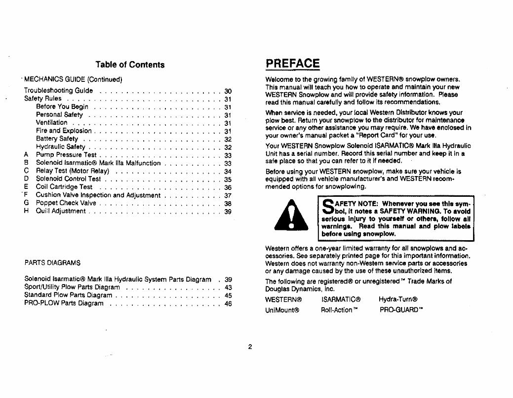
Table of Contents
. MECHANICS GUIDE (Continued)
Tro ubleshooting GuideSafety Rules . . . . , .
Before You Begin .Personal Safety _ .Ventilation , . . . .Fire and Explosion .Battery Safety . . . .Hydraulic Safety . . , . . . . ,
A Pump Pressure Test. . , . , . . . , . . .8 Solenoid Isarmatic(ã Mark 111a Malfunction
C Relay Test (Motor Relay) ,...., . , ,
D Solenoid Control Test . . . . . . . . . , ,E Coìl Cartrídge Test ............. F Cushion Valve Inspection and Adjustment
G Poppet Check Valve, . , , . .. .,. . . .H QuíU Adjustment, , . . . . , . . . , . . . . . . . . .
. 30
3131
. 31
, 31
31. - 32
32. . , 33
. . 33
34. 35
. 36
. 37
3839
, + II . 'I
PARTS DIAGRAMS
Solenoid lsarmatjc~ Mark ila Hydraulic System Parts Diagram . 39Sport/Utility Plow Parts Diagram . 43Standard Plow Part$ Diagram. . . . . . , , 45PRO..PLOW Parts Diagram .., . . . . . . . . . . . . . . . , . i 46
PREFACEWelcome to the growing family of WESTERN$ snowplow owners.This manual wil teach you how to operate and maintain your newWESTERN Snowplow and wiU provide safèty information. Pleaseread this manual carefully and foUow its recommendations.
'Nen service is needed. your ioeal Western Distributor ~nows yourplow best. Return your snowp10w 10 the distributor for maintenanceservice or any other assistance you may require, We have enctosed inyour owner's manual packet a uReport Card" for your use.
Your WESTERN Snowplow Solenoid ISAÀMATlC~ Mark ilia HydraulioUnit has a serial number. Record this seriai number and keep it in asafe place so that you can refer to it if needed.
Before using your WESTERN snowplowt make sure your vehicle is&quipped with all vehicle manufacture,.s and WESTERN recom.mended options for snowp1owlng.
A SAFETY NOTE: Whenever you se this .ym.bot, it notes a SAFETY WARNING. To avoidserious injury 10 your.." or others. follow allwarnings. Read this manual and plow S.belf~beore using snowplow.
Western offers a one.year limited warranty for aU snowplows and ac-cessor,es, See separately pdn1ed page for this important informa1ion.Western does not warranty non-Western seNice parts or accssoriesor any damage caused by the use of these unauthorized items.
The following are reg.stered(ö or unregistered ™ Trade Marks ofDouglas Dynamics, Inc.
WESTERNc. ISARMA TICCB
UniMountff Rorr-Act(on ™Hydra.Turn(ã
PRO-GUARD ,.
2

OWNER'S MANUAL, GETTING TO KNOW YOURSNOWPLOWBLADEThe blade on your new WESTERN(( snowplow is consttuoted ofheavy gauge steel. To increase rigidit and strength, the blade is rein-forced with several vertical ribs. The top edge is rolled for addedstrength and improved appearance.
The exclusive RoII.Aolon''' blade is designed to roll snow ahead andto the side instead of just pushing snow. This action means you canmove more snow and move it faster uaing Jest power, saving fuel andreducing wear and tear on both vehicle and plow.
. The blade has a replaceable high-crbon steel cutting edge bolted tothe bottom. This cutting edge is reversible to equalize wear (ex.ceptSportUtilty plows) and should be replaced when it is worn to the bot..tom edge of the blade. (See Regular Maintenance and Adjustments.)
The blade also features large. adjustable disc-type skid shoes. Theserotate 36 for longer wear and better blade flotation over all surfaces.For severe servicei heavy duty diso shoes are available from yourlocal Western Distributor.
Your new blade is protected with PRO-GUARD JM - a baked-on pow.der finish that resists crackingt corrosion, scratching and rust. ThePRo.aUARDTII coating - many times thicker than paint ~ wit! maintainits lustér and glossy good iooks longer than any other snowplowblade finish in the industry. It can be touched up when necessary.
. Blade guides with reptaceable flags are furnished with your completesnowplow. These help improve operator visibility and blade control.
BLADE ACCESSORIES.. OPTIONALSnow Denector - Optional snow deflector keeps snow off thewindshield and away from the radiator. The defleotor improvesRoll.Actlon T04 and increases plow efficiency. (Not for SportUtilty
Plows)
3
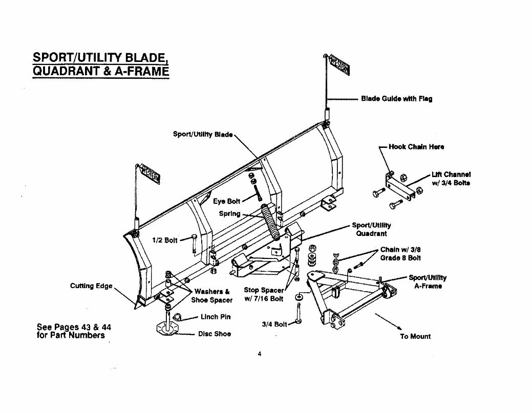
SPORT/UTILITY BLAD~QUADRANT & A-FRAME
Sport/Utilit BI.de
Cuting Edge Stop Sp.cer ~wI 7/16 Bolt ~
3/4 BoltJSee Pages 43 & 44for Part Numbers Disc Shoe
4
Blade Guide wih Flag
li Ch8nnelwl3/4 Bott
SportUtilitQuadrant
SpU1UhyA..Freme
~To Mount
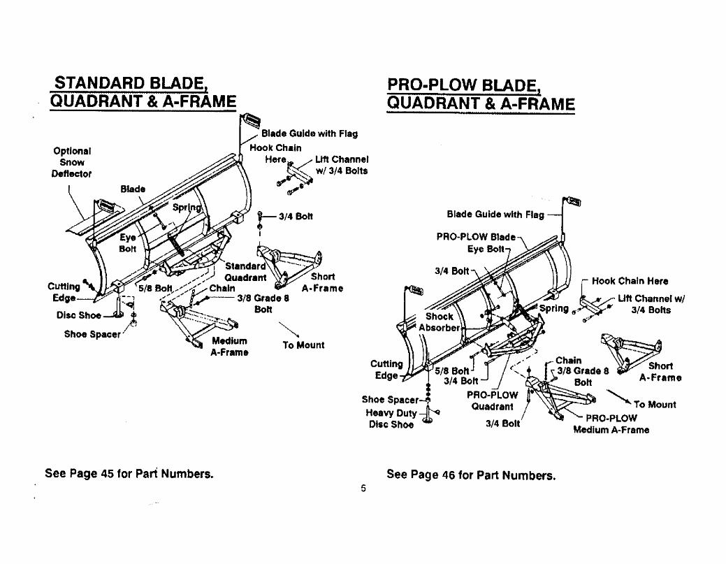
STANDARD BLADE,QUADRANT & A-FRAME
OptionalSnow
Deflecor
Blade Guide with FlagHook Chain
Here r¿ Uf Channel~ w/3/4 Bolts
d11
'~To Mount
See Page 45 for Part Numbers.
PRO-PLOW BLADE,QUADRANT & A-FRAME
Blade Guide with Flag
PRO-PLOW BladeEye Bolt
~OOk Chain Here..
Uft Channel wiSpring (J;9~ w 3/4 Bolts
r:'"
Shoe SpacerHeavy DutyDisc Shoe
~-..-...
Chainr: 3/8 Grade 8 · ShortI ~ Bolt A- Frame
""TO MountPRO-PLOW
Medium A-Frame
See Page 46 for Part Numbers.5
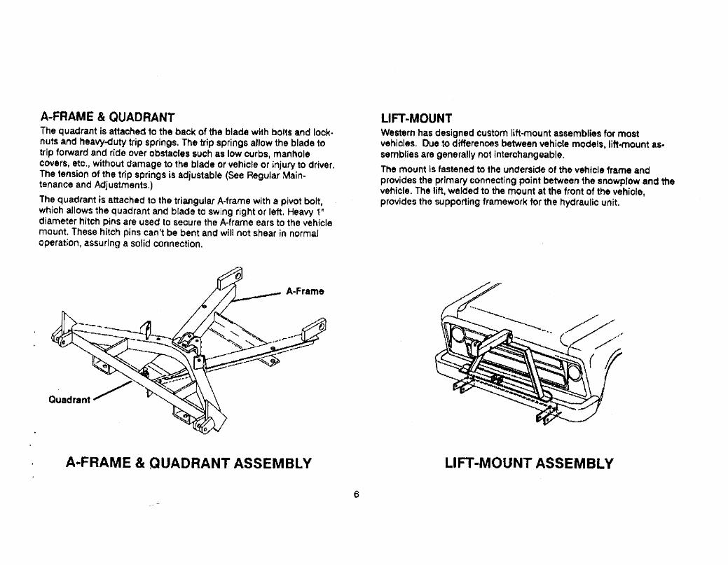
A-FRAME & QUADRANTThe quadral1t is at1ac:néd to the back of the blade wHh bolts and lock.nuts and heavy-duty trip springs. The trip springs allow the blade totrip forward and ride over obstao(es slJch as low ourbs, manholecoverst etc,i without damage to the blade or vehicle or ¡njury to driver.The tension of the trip springs is adjustable (Sée Regular Main-tenance and Adjustments.)
The quadrant is attached to the triangular A-frame with a pivot bolt,which allows the quadrant and blade to swlng right or left. Heavy 1 ~diameter hitch pins are used to secure the A.frame ears to the vehiclemount. These hitch pins cantt be bent and wil not shear in normaloperation, assuring a solid connection.
Quadrant'/ '-
A..FRAME & QUADRANT ASSEMBLY
LIFT-MOUNTWestern has designed custom lift-mount assemblies for mostvehicles, Due to differenoes between vehicle models. lift.mount as-semblies are generally not interchangeable.
The mount is fastened to the underside of the vehicle frame andprovides the primary oonnecting point between the snowplow and thevehicle. The lift, welded to the mount at the front of the vehiole,provides the supporting framework forthe hydraulic unit.
LIFT-MOUNT ASSEMBLY
6

HYDRAULIC POWERWestern's Solenoid ISARMATICQi Mark Ula System provides 8 fast anduniform speed of lifting and angling. The system raises the b~ade in 2seconds and angles side to side jn less than 4 seconds.
The ISARMATIC~ Mark lUa reservoir shourd be filled with automatiotransmission (ATF) ftuid (Mobil One or Texaoo 1531 Ajrcraft HydraulícOil may be used for low temperature operation). Push rift channel allthe way down. Remove fill plug (behind motor) and fluid fevel prugon the driver-side front corner of reservoir, Fill reservoir through fillerplug hole un1í1 fluid runs out of fluid revel hole. Replace both plugs.
Alternate method: Push lift channel aU 1he way down. Remove fiJplug (behind motor). FI1I reser.voir only through fil opening (it ¥ Q¿O~~dis designed to prevent overlill- a eihg). Reservoir is full when the'oillevel reaches hole threads. dbReplace fill ptug. IISYSTEM CAPACITY
Solenoid ISARMATIC(ä Markila Unit Reservoirs -1-1/2 quarts,
Solenoid ISARMATIC~ Mark fia& 10" Hydra-TurnC8 Rams -.2-1/8 quarts.
Solenoid on Fil PlugISARMA TIC~ Mark
'Ilta & 6" Hydra- Fluid Level PlugTurnCI Rams -1-7/8 quarts.
SOLENOID ISARMATIC~ MARK ilia
SOLENOID CONTROLThe solenoid control is électrica¡ly powerèd through the ignition (key)switch of your vehicle and is protected by a replaceable 10 amp in.line fuse. The ON/OFF switch allows you to turn off the control andprevent blade movement even when the ignition is on.
ON/OFF Switch
Control Lever
Solenoid Control
Indicator Light
MoldedConnec1or
Cable Cramp
Control eracke1
MountingScrews
Adjustable Positions
SOLENOID CONTROL& MOUNTING BRACKET
7

HYDRA. TURN~ ANGL.INGHydra- Turn~ power angling gives you full oontrol of the plow fromwJ1hjn 1he cab of the vehicle - yoù1fl never have to get out in the
. snow to change the angle of the blade, Two single-acting hydraulic.rams hold the bfade at the desired angle. The rams are operated by1he solenoid control.
The Solenoid ISARMATIC~ Mark lllaValve Manifold has two cushion valves
built in 10 prevent damage to theblade or vehicle if obstacles are hit.\len the force against the blade
causes pressure in an extended ram. to exceed set limits. the cushion valveopens allowing oil to escape and the
. ram pi u nge( retracts.
NOTE: l" the event of Hydra-turn\! angling failure, place a5/8" bolt through the holes In theA-frame and quadrant (not ap-plicable 10 Sport/Utilty plows).
This win hold the blade In positionuntil the problem is corrected.
A WARNING: Keep well clear of the. bl.dewhen It ls being raise, lowered. or angled.Do not stand between the vehlcl. ind blade ordirectly In front 01 blade. lf the blade hits you ordrops on yout you could be seriously Injured.
Hydraulic Pr...ur. Hoses
~ TIV, Hydraulic
QuickCoupler
'-- Male Elbow
Quadrant
HYDRA-TURN(( ANGLING H.ydr.- Turn~ Ram
Ram Packinga

HEADLAMP KITThe headlamp kit includes a set of rectangular dual-beam halogen11eadlamps plus comblnatjon park and turn signals.
A patented pre.wlred harness with plug-in module requires no head.tamp wire splicing. Ughts conform to federal safety standards.Ùse plow headlamps ONLY when plow ~s attached. Use vehlcle head.lamps when plow is NOT attached.
Replacement 2E1 Seal Beam headlamps are available through Chrys-ler Product dealers or may be ordered through NAPA dealers or otherauto parts stores,.
CAUTION: Lights may be damaged by brush-type aulomaticcar washes...
A WARNING: Before traveling, pol1ion bl.deso h doe not block headlamp beam. Donot change blade position while 1ravellng.
//// //
(
LOW PROFILE HEAD LAMP KIT9
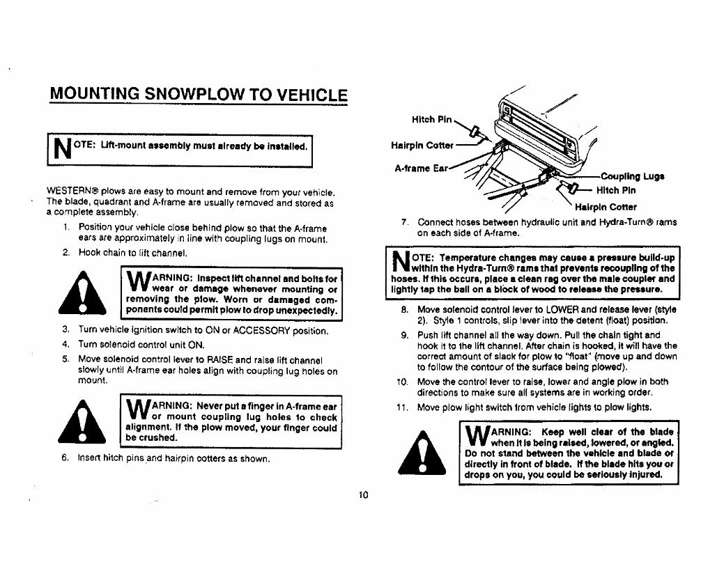
MOUNTING SNOWPLOW TO VEHICLE
NOTE: Uf-mount assembly muslelready be installed.
WESTERN~ plows are easy to mount and remove from your vehicle.The blade, quadrant and A.frame are usually removed and stored asa complete assembly.
1. Position your vehicle close behind plow so that the A.frame
ears are approximately in Hne with coupling lugs on mount.
2. Hook chain to lift channeL.
A WARNING: Inspect lif channelind bolts forwear or damage wh--ne"er mounting 01removing the plow. Worn or damaged com.ponents coufd permit plow to drop unexpe1edly.
3. Turn vehicle Ignition switch to ON or ACCESSORY position.
4. Turn solenoid control unit ON.
5. Move solenoid control lever to RAISE and raise lift channelslowly unt¡1 A.frame ear holes align with coupling lug holes onmount
A WARNING: Never put a
finger in A-frame earor mount coupling lug holes to check
alignment. If the plow moved. your finger couldbe crushed.
6. Insert hitch pins ,and hairpin totters as shown.
10
/ _/Hitch Pin l~ ~..Hairpin Cotter~' ~
'"
A.frame Ear.. Caupllng Lug.~ Hitch Pin
Hairpin Coner
7. Connect hoses between hydraulic unit and Hydra..Turn~ ramson each side of A.frame.
N OrE: Temperature changes may cause a pressure bulld.upwithin the Hvdra- Turn(( ram. that prevents recoupling of thehoses. " this occurs, place a clean rig over the male coupler andlightly 1ap the ball on a biOck ot woo to rele... the pressure.
a. Move solenoid control lever to LOWER and release lever (stye2). Style 1 controls1 slip lever into the detent (float) position.
9. Push lift channel at! the way down, Pull the chain tight andhook it to the lift channeL. After chain is hool(ed, it win have thecorrec1 a.mount of slack for prow to h1toat" (move up and downto follow the contour of the surface being plowed),
10. Move the control lever to raise, lower and angle plow in bothdirections to make sure aU systems are in working order.
11. Move plow light switch from vehicle lights to plow lights.
A WARNING: Keep well clear of the bladewhen It Is being raise, lowered, or angled.Do not stand between the vehicle and blade 01directly in front of blade. If the blade hl1s you ordrops on you, you could be seriously lnjured.

OPERATING YOUR PLOWCONTROLLING THE BLADETURNING ON
Turn vehicle ignition (Key) switch to ON or ACCESSORY position.
Move solenoid centro' ON/OFF switch to ON position. The control in.dicator light (red) should light whenever the control ON/OFF swjtchand the lgnjtjon (key) swllch are both turned ON.
.Styl.1 Controo Label
Style 2 Control.. Moving lever to lower wilautomatically allow blade float (even whenlever returns to neutral position).
To cancel float - momentarily move lever toraise.
RASE:
LOWER (Float):
ì'
!~¡ Iii'lt (( I
~ - 0 ---j
--~ArI!V'\b ..
Move control lever UP (forward) to raise bladeuntil blade has reached desired height.
Move lever DOWN (back) to lower blade.
For blade float (This aUows the blade to moveup and down to follow the contour of surfacebeing plowed.)
Style 1 Control - Leave lever in detent forblade float.
II 'Turning off the contro1 ON/OFF switch or thei:. CD"':. vehicre igni1ion (Key) switch will also cancel
float. Angling left or right does no1 cancel "oat.Style 2 Con1rollabel
ANGLE LEFT: Move lever to the LEFT to angle blade to theleft until blade has reaohed desired angle.
ANGLE RIGHT: Move lever to the RIGHT to angle blade to the"~ght until blade has reaohed desired angle.
LOCK BLADE IN POSjTION: With control lever in neutral, turncontro10N/OFF switch to OFF.Bladé is now locked and cannotbe accidentally moved.
A WARNlNG: To prevent accidental move-ment of the blade, always turn the ON/OFFswitch to OFF whenever plow is not In use.
CAUTION: 00 NOT hold solenoid control lever In RAISE,ANGLE LEFT or ANGLE RIGHT position more than 5 secondsafter blade has reached desired position. To do so Increasesbettery drain and could result In motor burn-out.
11
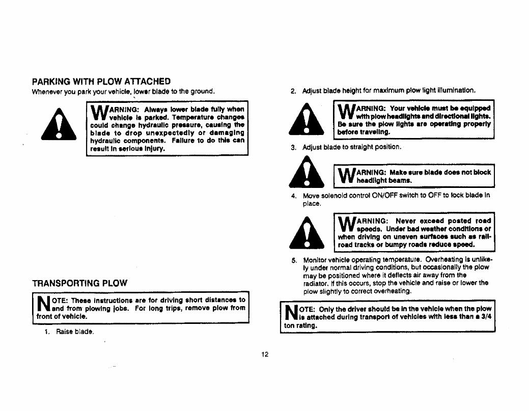
PARKING WITH PLOW ATIACHEDWhenever you park your vehicle. lower blade to the ground.
..
Â
WARNINO: Alway. lowr blade fulty whenvehlel. I. parked. Temperature changecould change hydraulic preuurii cau.fng thblade to drop unexpec1edly or damaginghvdraulic components. Failure 10 do this canresult In seflous Injury.
TRANSPORTING PLOW
NOTE: Thne Instructions' are for driving shor1 dlstanoes toand 110m' plowing jobs. For long trips. remove plow fromfront 01 vehlcle.
1, Raise b1ade.
2. Adjust b1ade height for maximum p'ow Ught iIumlnatlon.
Â
WARNING: Your vehicle must be equippwth plow headlIght and dlreclolllgMs..Be aur. the plo light .re opating proprlybeore traveUng..
3. Adjust blade to straight posÎtion~
Â
WARNING: Malee sure blade doe not blockheadllght beam.~
4. Move solenoid control ON/OFF swi1ch to OFF to lock blade inplace.
Â
WARNING: Never exc.ed posted roadspes. Under bad weether conditions or
when driving on uneven surfce .uch .. rail..road tracks 0' bumpy road. reduce spe.
5, Monitor vehicle operating temperature. Overheating is unUke-
Iy under normal driving conditions. but ocslonany the plowmay be positioned where it deflects air away from theradíator. If this occurs, stop the vehicle and raise or lower theplow slightly to correct overheating.
NOTE: Only the driver should be.ln the vehicle when
the plowIi attached during transport of vehicles with les than 8 3/4
ton rating.
12

PLOWING SNOWGENERAL INSTRUCTIONS
1. Before plowing, make sure you know of any ob~tructions hid-den beneath the snow, such as bumper stops in parking lots.,curbs, sidèwalk edges, shrubs, fences. or pipes sticking upfrom the ground,
CAUTION: To prevent damage to plow or vehicle. "ag anyob.truct~on. that are hard 10 loca1e.
2. Only the driver should be in the vehicle when plow is attached
for plowìng.
A WARNING: Always we.' Mat beh whenplowing .now. A hidden ob.'ructlon could
cau.. the vehlele to atop suddenly, throwing youforward and Injuring you.
3. Plow during the storm rather tha~ let1irrg snow ac(;umulate.
A WARNING: Never plow whh head out 0' thevehicle window. Sudden .'Opi or protrud-Ing objects could cause ~evere neck or headInJurle..
4. VVen you are stacking snow, begin raising the blade as youcome cloge to the stack. This will let the blade with its loadride up onto the stack,
CAUTION: Never pile snow with the blade eng1ed more thanhalfway Of the bumper could be damaged.
SPECIAL SNOW CONDITIONS- Hard-packed Snow
1. Raise the disc shoes so that the cutting edge comes intodìrect contact with the pavement. (See Regular Main-tenance and AdJustments.)
2. Use lowest gear to place maximum power behind cuttingedge.
3. Ar angled blade is mote effective to remove hard-packedsnow.
Deep Snow
1. Shear off top layers by plowing with the blade raised 3 10
4 inches lor the initial pass.
2, Bite ínto the edges using only partial blade width until job
is cut down to size for full blade plowing. Rule of thumb:6" snow may be plowed with entire blade width; 9" with314 b1ade; 12" with 1/2 blade. Experience and "feel" are
the best guides.
3. When plowing deep snow, be sure 10 keep vehiclemoving.
4. Secure ballast behind wheeis for be"er 1raction. Recom.
mendations: full-size pick-ups: 500-700 Ibs.; compactpick-ups: 300 lbs,; sport/utility vehicles: i 50 Ibs.
5. For increased traction use tire chains.
1 ~j
CLEARING DRIVEWAYS1. Head into drive wi1h angled blade and plow snow away from
buildings. V\den drive by rolling snow away from bui'ding.
2. If buiid.ng is at end of driveway, plow up to withfn a vehicle
length of building. Then push as much snow as possible offdriveway.
3. Vvth raised straight blade, drive through remaining snow tobuilding. Drop blade and "back-drag" snow away from bU1ld~
ing at 'east one vehicle length. Repeat i1 necessary.
4. Back vehicle to building door and plow forward toward street i
removing remaining snow from driveway. Check municipal or-dinances for disposal of snow.
CLEARING PARKING LOTS1. Clear areas in front of buildings first. \\th raised blade. drive
up to building. Drop blade and ~back-dragl\ snow away frombuitdings, vven snow is clear of buildings. turn vehiclearound and push snow away from buildings towards olreredges of lot.
2. Plow a sing\e path down center in tong direction,
3. Angle plow toward the long sides, and plow succssive strips
lengthwise untH aré8 is cleared and snow is "stacked" aroundouter edges.
4. If snow is too deep to clear in abol/8 manner, clear main traffic
lanes as much as posslble,
14

REMOVING SNOWPLOW & STORAGE1. Lower the plow to the ground (keep tension on chain). Style 2
controls. momentarily move control to raise position or turnOff ON/OFF switch. Stye 1 controlsf move solenoid control tonéutra-I.
.Å WARNING: Keep hand. and fee cleir ofb'ade and A-frame when removing ormounting plow. Moving or tailng ....mbll.. can Ipinch or crush. i
2. Dtscnnect hose CCuplers between Solenoid lSARMA TIC~
Mark uta and Hydra- Turn(f rams,
A Connect curb-side ram hose ¡nto the qu¡ck ooupler on thedriver-side ram.
8. Loop Solenoid ISARMA TlC(ß Mark ila hoses around the
lift assembly and couple hose into manifold quick coupler.
This will protect the quick coupler ends and keep foreignmatter out of the quick coupters whiie the snowplow is offthe vehicle.
NOTE: Beuse of hydrauUc pressure, hoses may be herd todisconnec Immediately after angling blade. Allow time forsystem pressure to blee off to tank.
3, Pull hairpin cotters from hitch pins at rear of A.frame andremove hitch pins. After disassembly. replace hi1ch pins andhairpin cotters in A.frame ears for ready access when reinstall~ing plow.
4. Move the solenoid control lever to LOWER (float) position.
5. Push the nft channel all the wa.y down. Leave lift channel indown position to protect lift ram from rusting and pitting.
6. Unhook chain.
WARNING: Inspect plow components andbolts for wear or damage whenévermounting or removing the plow.. Worn ordamaged components'could permit plow to dropunexpeC1edfy.
7. Move oontrol ON/OFF switch to the IIOFF" position. Style 1con1rols, return control lever to neutral.
8. Move plow light switch from plow lights 10 vehicle lights posi.tion.
Å
I NOTE: For fong-term storage. grease exposed chrome sur-faces of the Hydra.. Turn(! rams 10 prevent rust.
CAUTION: To preven1 the shock absorber on the PRO.
PLOWA.1r.me from collecting witeft s10re plow with A.frame
horizon1af.
During the off season, the solenoid control and bracket can beremoved from the dash/floor bracket by disconnect¡ng the moldedconnector in the cab and (emoving the four mounting screws, Storecontrol and bracket in giove box of vehicle.
15
. MAINTENANCE
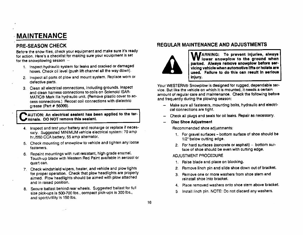
PRE..SEASON CHECKBefore the snow flies, check your equipment and make sure it's readyfor action. Here's a checklist for making sure your equipment is setfor the snowplowing season -
1. Inspect hydraulic system for leaks and cracked or damagedhoses. Check oil level (push lift channel all the way down).
2. Inspect all parts of ptow and mount system. Replace worn ordefective parts.
3. Ciean at! electrical connectiorrs, including grounds. Inspectand clean harness connections 10 coils on Solenoid tSAR-MATIC(ß Mark ila hydfauUe: unit. (Remove plastic cover to ao-cess connections,) Recoat coil t:onnections with dielectricgrease (Part -# 56),
CAUTION: An electrical sealant has ben applied 10 the ter-minals. DO NOT remove this sealant.
4. Inspect and test your battery and recharge or replace if nece$-
sary. Suggested MINIMUM veh;cle electfica\ system: 70 amphr'/550 CCA battery~ 55 amp alternator.
5. Check mounting of snowplow to vehicle and tighten any 100S&fasteners.
6. Repaint mountings with rust resistant, high grade enameL.Touch-up blade with Western Red Paint avaí'able in aerosol orquart oan.
7. Check windshield wiperst heater, and vehiole and plow lightsfor proper operation, Check that plow headlights are properlyaimed, Plow headlights should be aimed with plow attachedand in raised position.
8. Secure ballast behind rear wheels. Suggested ballast for fullsize pick-ups is 50700 Ibs.. compact pìck~ups is 300 Ibs"
and sport/utilty is 150 Ibs.
REGULAR MAINTENANCE AND ADJUSTMENTS
WARNING: To prevent InJuries, alway.lower snowplow to the ground whenparked. Alway. remove snowplow beore se'''vlclng vehicle when aU1omotlve 1m. or hols1. .r.
used~ Failure to do this can result In Mrlou.Injury..
Your WESTERN(B Snowplow is designedfor rugged. dependable ser..vice, But like the vehicle on which It Is mountedi it needs a certainamount of regular care and mafn1enanoe. Check the fonowing beforeand frequently during thè plowlng season:
Make ~ure all fastenerst mounting bolts. hydraulic and electri-cal con nections are tig ht,
Check aU p'ugs and sea(s for oil leaks. Repair as necessary.
Disc Shoe Adjustment
Recommended shoe adjustments:
1, For gravel surfaces - bottom surface of shoe should be
1/2-' below cutting edge.
2. For hard surfaces (concrete or asphalt) - bottom sur..
faoe of shoe should be even with cutting edge.
ADJUSTMENT PROCEDURE
i, Raise blade and place on b\ooking.
2. Remove finch pin and slide shoe down out of braoket.
3. Remove one or more washers from shoe stem andrein s1all stt oe into bracket.
4, Place remoyed washers onto shoe stem above bracket.
5. In$talllinch pin. NOTE: 00 not discard any washers.
A
16

FFEGULAR MAINTENANCE AND ADJUSTMENTS (Condt.)- Cuting Edge
To equal ize wear i cutting edge can be reversed (exceptSportUtility Plows). Replace cutting edge when worn to thebottom of blade sheet.1. Raise blade and place blocking under A.frame.
2. Remo'le cutting edge, and turn end for end.
3. Reinstall.
NOTE: Sport/UtUity cutting edge is not reversible.
Trip Spring AdjustmentTo adjust trip spring tension, adjust the eyebolts located atthe top of the blade.
1. Loosen locknut (nut closest to spring).
2. Tighten adjusting nut (nut c10sest 1o ptow) until coilsbegin to separate. VVen tension is properly adjusted. asheet 01 paper shou Id pass between the second andthird coils.
3. Tighten tooknut.
PRO..GUARD 1W Blade Finish
i1 the PRo-GUARD~'" powder coated finish is nicked orscratched, repair the blade surlaoe with Western Red Paint inaerosoi or quart can.
Black Iron Moun1 Parts - Powder Coated or PaInted
Parts should be cleaned and touched up with a rust resistanthigh-grade enamel paint.
HYDRAULIC SYSTEM- Oil Level
Push rift çhannel all the way down. Remove 1m plug (behindmotor) and fluid level plug on the driver.side front corner ofreservoir, Fill reservoir through filer plug hole until fluid runsout of ffuid level hole, Replace both plugs.
Alternate method: Push tift channel all the way down.Remove fin plug (behind motot), Fill reservoir on1y throughfil opening (it is designed to prevent overfiltng). Reservoir isfuU when the oll level reaohes hoie threads. Reptace fiB plug.
Oil Fill Plug
Fluid Level Plug
Drain Plug
- Annual Fluid Change
IMPORTANT: Change fluid at 1he beginning of each plow-ing season.
1. Remove drain plug located in the bottom of the rightfront corner of the reservoir (see diagram).
2. Comple1e!y drain the hydraulio reservoir.
3. Refill through fill hole with new au10matic transmissionfluid (ATF). (Mobil One or Texaco 1537 AiroraftHydraulic Oil may be used for low-temperature opera~tiorr. DO NOT mix d¡fferent types of oils.)
17

- System Capacity
Solenoid ISARMATICCB Matk Ilia Reservoir - 1-1/2 quarts..Solenoid lSARMATIC(8 Mark Ilia (1-1/2" Ram) with 1011 Hydra-
Turn~ Rams - 2.1/8 quarts.Solenoid ISARMATICtB Mark ila (1-1/2u Ram) wrth 6" Hydra-
Turn(8 Rams - 1.7/8 quarts.
CAUTION: FiJ reservoir through 1ii hole ONLY. Never fillthrough motor/pump opening. Overfilling can damage theunit
lift Ram
Motor
Pum p InletFit1er Screen
Solenoid ISARMA TrC~Mark ila
(Hydraulic Unit)
- Packing Nut AdJustment
Periodically check lift ram and Hydra-Turn(f ram packingnuts for tightness. H packtng nuts are loose or leakage ap-pears while lifting or angUng plow, tighten not more than 1j4turn after you feeJ packing nut contact the packing.
CAUTION: Do not overtghten pecking nut.
Packings not used for a period of time may show signs of oilweep. This will usually stop after use.
- Pump In'et Filter ScreenClean 1he pump rnlet file, screen whenever the pump isremoved. If the screen is damaged, replace it. Torque dIe-cast pump mounting capscrews to 175-185 in.-Ibs, motormounting capscrews to 15/20 ft..bs.
EMERGENCY PARTSWe suggest that you keep Western Emergency Parts Kit #49205 andthe followirrg items in yout vehicle for emergency use.
1 - 93028K Hitch Pin 1 II x 3-1/2"i ~ 919$5K Hairpin Cotter 5/32jl1 .90045 Chain 80113/8"-16 x 2-1/211 - Grade 81 ~ 91333 Locknut - 3/8".161 - 56134K Relay - Solenoid Hydraulic System1 - 10" Adjustable Wrench1 - Medium Screw Driver1 - Pair of Pliers1 . Quart Automatic TransmLsslon Fluid (ATF)
Always use Western des.igned and tested replacement parts.18

(0

~
en o r- m z o - c - UJ )) :c 3: ;; -- - '0 ~ 3: :: :I "
3: m n :r ~ z - o (I " c: - C m
- - - D)

SOLENOID ISARMATICCI MARK iliaASSEMBLY DIAGRAM
Motor
Solenoid Control
To GooGround
.-.:Relay - SolenoidHydraulic System(Motor Relay)
./ Optional Reversed.~~.. /' PositionII 'o..~).
,."..
ON/OFF Switch
5/1 641 Ri ng
TerminalCon~rol Bracket
Dash or Floor Bracket
SolenoidrSARMA TIC~
Mark lUa
Self StrippingCon nector
(Blue)
, Valve ManifoldManifold Cover
To GoodGround
Vehicle Wire Controlled byIgnition (Key) Switch
21

THEORY OF OPERATIONThe Solenoid I$ARMATIC(8 Mark IlJa Hydraulic System performs fourfunc1ions:
RAISE the snowplow
LOWER 1he snowplow
ANGLE snowplow RIGHT
ANGLE snowplow LEFT
For all functions, the vehicle ignition (key) switch must be set at ON orACCESSORY. and 1he solenoid control ON/OFF Switoh must be ON.
For RAISE. ANGLE RIGHT and ANGLE LEFT, cartridge vafve spoolsshift, and 1he motor runs.to drive the hydraulic pump. For LOWER, acartridge valve spool shifts, but 1he motor does no1 run.
ELECTRICAL OPERATION OFMOTOR'Nen the control lever is moved to RASE,LEFF. or RIGHT, a switoh inside the controlcloses. This allows electrioal current toflow through the switch, through tlle con ofthe motor relay. through the ground, andback to the battery. The current frow
through the motor relay coil closes themotor re~ay contacts. Closing these con-
taots connects heavy cables between themotor and the battery. These cables carrya targe curren1 flow which enables themotor to run,
r Ground throu:~ engine block
by cable directly to battery
Motor RelayMotor
liftRam
ContactsColi
., IIlIi ·
Ignition(Keyed) .Switch
3-Way
4-Way
FuseHolder
(10 Amp)0'0''8om
SwitchDiodeIndicator Light
Coil Cartridge Valve As&emblyRelay... Ftoa1
ON/OFFSwitch
Solenoid Control(Style 2)
ELECTRICAL SCHEMATIC
22
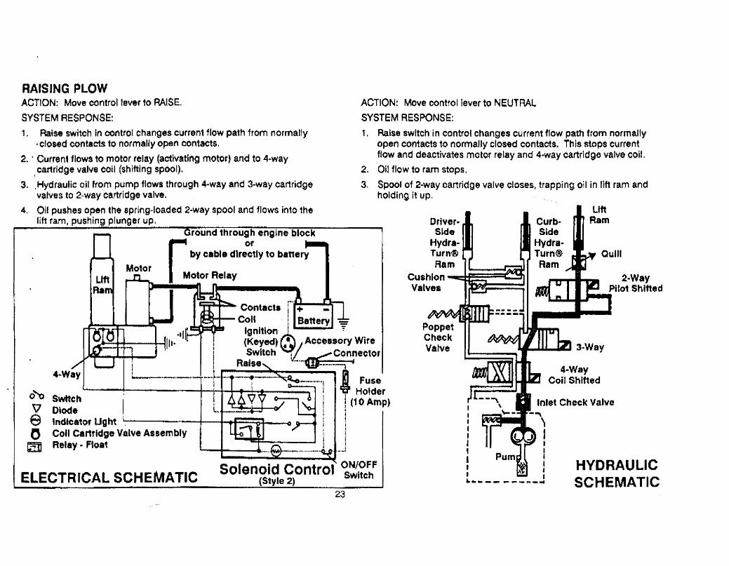
RAISING PLOWACTION: Move control lever to RAISE.
SYSTEM RESPONSE:
1. Raise switoh in control changes curren1110w path 1rom normally
. closed contacts to normally open oontacts.
2. . Current flows to motor relay (activating motor) and to 4..waycartridge valve coil (shifting spool),
3. .Hydraulic oU from pump flows through 4-wayand 3-way cartridgevalves to 2-way cartridge valve.
4. Oil pushes open the spring-loaded 2-way spool and flows into the
lift ram, pushing plunger up.
ACTION: Move control lever to NEUTRAL
SYSTEM RESPONSE:
1, Raise switch in control changes current flow path from normally
open contacts to normally closed contacts. This stops currentffow and deactivates motor relay and 4.way cartridge valve coil.
2. Oil flow to ram stops,
3. Spool of 2-way oartridge valve closes, trapping oil in lift ram andholding it up.
0'0\JeoIi
SwichDiodelndlca10r LightColi Cartridge Valve AssemblyRelay - Float
,""r
Contacts : +
coie ! BatteryIgnition ¡ ';(Keyed) ~ J Accessory WireSwitch !L.. ~ Connector
Raise "'."1U~~ i
'~-~"""j i l Fuse: ,Holder
! (10 Amp)1
i
1
l. i..,...!
Driver-S~de
Hydra-Turn~Ram
CushionValves
2..WayPitot Shifted
rGrOUnd throu~~ engine block
by c8ble directly to banery
Motor RelayMotor
4..Way
IiIjI: II Ii t~-~--,_.,- .-....~_..~
4..WayCoil Shifted
ELECTRICAL SCHEMATICSolenoid Control ON/.OFF
(Style 2) Switch23
Inlet Check Valve-~
~l..llI. ;...... _.. .. ......-..
HYDRAULICSCHEMATIC

LOWERING PLOWACTION: Move control lever to LOWER.
SYSTEM RESPONSE:
1. Lower switch in control closes.
2. Current flows to 2-way cartridge valve coil (shifting spoof).
3. Hydraulic oil escapes from the lift ram and ffows past the adjust.able quiU (which controls 1he rate of blade lowering), through 1he3-way and 4-way cartridge valves, and back 10 the reservoir.
Ground through engine block~ Ofby cabLe directly to battery
Motor Relav
Contacts r' +Coli I Battery ..Igni1ion '* Acce8s~ry Wire(K'~)\\l ConnectorS~h:..... ...~.."..~ '
R Fuse~~L lI HolderSwitch i · I ~: ¡ (10 Amp)D~de ¡ , ¡i._.._,.,____~..__,__.~..",~ ..~.."...._ ,~'.. _h....'...".. . '.__Q._". !Indicator Light. L. ..¿- Lower i: ~ ON/OFFCoil Cartridgé Valve Assemblv '- "."...."..._,_.w.~_..j! .Relay . Float ,_.J Switch
0'0t¡eob:ELECTRICAL SCHEMATIC
Solenoid Control(Style 2)
24
Driver..Side
Hydra..Tu rn~Ram
CushionValves
LltRam
HYDRAULICSCHEMATIC

PLOW FLOAT/CANCELING
There are two styes of controls. Each operates the same except forthe float function. Identify control style by label on control.
ìc0l"
I U)irOA''
mm
..iLto-~ l !. "T TlL i.
ml:' CD ".:"
S1y. 2 Controllabel Style 1 Control LabelSee Next Pag e.
PLOW FLOAT (Style 2 Control)ACTION: Move con1rol ~ever to lower and release lever to neutral.
SYSTEM RESPONSE::
1, Lower switch in control closes.
2. Current ftows to 2-way cartridge vafve coif (shifting spool) and
through float relay coil (closing normally open contacts).3. When control lever is released - lower switch in oontrol opens.
CurC'en1 flows through the closed contacts of the float rela.y to the2..way cartridge valve coil (holding spool shifted) and to the float
rela.y cOti (holding contacts closed)
4. The 2-way spool remains shiftedi whioh permits the blade to fol..low the road oontour, or "floatl.
Normally ClosedContacts Raise Switch
IU1IUUM."ItU'*
o 1'4
~ ;Lower ¡. ~..... .....t....i..iin'... ..."...,,_'.......11111............11...
ON/OFFSwitch
ToGround
II tll.i,,",.. .....I.. ......... n ...1
Current Flow in Float (Lever in Neutral)Style 2 Control
CANCELING PLOW FLOAT (Style 2 ContrOr)ACTION: Move control lever momentarily to raise to cancel
II float",
SYSYEM RESPONSE:
1. The normally closed contacts of the raise switoh are opened,
2. Current flow to the 2.way oartridge valve coil stops (spool closes)
trapping oil in lift ram and holding it in position.
3. Current flow through the float relay coil stops (relay contactsopen) .
NOTE~ \Nenever lever i~ moved to lower the piowi the plow wiU be infloat until: the control lever is moved to raise.
the control ON/OFF switch is turned off.the vehicle ignl1ion (key) switch is turned off.
NOTE: Plow can be angled while in float.
NOTE: H the float relay fails, the blade wil still lower and float as longas the lever is manually held in lower position.
25

ELECTRICAL SCHEMATIC (Style 1 Control) PLOW FLOAT (Style 1 Control)ACTION: Leave control lever in the detentposition (lower).
SYSTEM RESPONSE: The spool remainsshifted. which permits. the blade to followthe road contour. or 11joat~1
Ground through engine block
r orbV cable directly to banery
Motor RelayMotor
LiftRam CANCELING PLOW FLOAT
(Style 1 Control)ACTION: Returrcontto1 lever to NEUTRAL.
SYSTEM RESPONSE:
1, Lower switch in control opens.
2. Spool of .2Mway cartridge valve oloses.
trapping oil ;n 11ft ram and holding i1 inposition.
Contactscon
Ignition(Keyed) .Switch
.. IIHi'
.3..Way
4-WayFuse
Holder(10 Amp)
0"0 Switch
n Diodee Indicatof lighto Coil Cartridge Valve Assembly
Lower
Solenoid Control ~l;~::(Style 1)
ELECTRICAL SCHEMATICTo 2-Way ..." ,.__....."........M...n'_"_....n....'..._"....".......-L~r---'.
Coil ~ /I ..,.........M....M...._..___.._...."...'M..
ON/OFFSwitch
Current Flow in Lower/Float (Lever in Detent)Style 1 Control. '
To Ground
26

ANGLE RIGHTACTION: Move control lever to ANGLE RIGHT.
SYSTEM AESPONSE:
1, Angle right switoh in control closes.
2. Current flows 10 motor relay (activating motoi) and to the 3-way
cartridge valve coil (shifting spool).
3. Hydrautic oH from the pump flows through the 4-way cartridge
valve. pushes open the poppet check valv8. and flows into thedrrver.side Hyra- Turn(( ram to angle the blade to the right.
4. As 1he driver-side ram extends, the curb.side ram collapses, push..
ing its oil into the manifoldt through the shifted 3-way oartridge .valve, through the 4-way oartridge valve, and back 10 the reservoir.
r Ground throu:~ engine blok
by c.ble direcly 10 ~ttery
Motor Relay
Contacts
Solenoid Control~Styl. 2)
ON/OFFSwitch
ELECTRICAL ~CHEMA TIC
27
Driver..Side
Hydra.Turn~Ram
LiftRam
CushionV.lves
PoppetCheckValve
3NWayCoil Shrfted
4-Way
Inlet Check Valve
:.\::-:;:;.~::.::: :::: :;::'.:::~:::~.~~::;';::\::::~:::.:.:::~ :~:: ::::~.:::::::.~'::~:'
(:!!,~:~:;:(:. ,): :¡:¡(:\(:?::, 2i)JHYDRAULICSCHEMATIC

ANGLE LEFTACTION: Move oontrol lever to ANGLE LEFT,
SYSTEM RESPONSE:
1. Angle left switch in controf closes.
2. Current flows to motor relay (activating motor) af1d to the 3-way
and 4-way cartridge valve coils (shifting spoOls).
3. Hydraulio oil from the pump flows through the 4-way and 3-wayoartridge valves and into the curb-side Hyra",Turn(ê ram to anglethe blade to the left.
4. As the oil flows to the curb..side ram, it shifts the poppet checkvalve spool. opening the poppet in the manifold port for the driver..side ram.
5. As the.curb~side ram extands. the driver.side ram collapses, push-
ing its oil into the manifold. 1hrough the open poppet check valve,through the 4..way cartridge vafve, and back to the reservoir.
Motor
r. Ground through engine block
orby cable dlrectly to battery
Motor Relay
'1"
Contacts i +Coli I Batteryi rrlgnltlon ~. AccessorÝ Wire
(Keyed) . 1/
i Switch ~L.~:':nl:0r4.Wa~ i_.._.._....H....HM.........-T-i-'f- , :.....-.....- i" Fuse- i I ((------.. i~ l-..........---- -----.......................- "'1-' ..1...... --- LL'r. ......., 6 i î i Holder
~ SwItch L. _~:~- -:~-~ I ~ ; 1(10 Amp)v Diode ' .._... ~ re . ! IIndicator light ¡ ¡o Coil Cartridge Valve Assembly i ltã Relay · Float _-.ELECTRICAL SCHÉMATIC Solenoid ControlS Ie 2
ON/OFFSwich
28
Driver-Side
Hydr..Turn((Ram
CushlonV.lves
PoppeCheckValvePilot
Shifted
Curb-Side
Hydra-Turn~Ram
p:I::n:I ':'.
L:L:, ,:''.~.' . . ~ , ...... ". . ... . ... i
'¡r:: ;j, f:)i!'¡;!:¡ ::¡¡;:::¡j:¡¡¡¡!¡:ij:i¡:;i:i::ji;i¡.¡~:'
¡:~~ ;~~ :~:;~~.j ~;jf. ~~¡j~ ~~~~¡ .;~~~~ f~~~~:~~~~~~~;~~~ ~~~:.: ~:. ~~~~:::~~¡~j:~~~~~~~~;~
UfR8m
3-WayColi Shlted
4-W.yColi Shifed
HYDRAULICSCHEMATIC

CUSHION VALVES'Nile pJowingl oil is trapped in the extended Hydra-Turr(ß ram. Whenthe blade meets an object pressure rises in the extended Hydra-Turn\B ram. As pressure in the ram exceeds the spring force holdingthe checkball against the seat. the checkball unseats. Tn rs allows oilto flow to the collapsed rami and angles the blade in the oppositedirection, preventing damage to the hydraulic system! blade orvehic1e. Oil is uapped in the curb..side ram by the 3.way cartridgevalve and in the driver.slde ram by the poppet check valve.
2-WayCoil Cartridge
Valve
3..WayColi Cartridge
Valve
4.. WayColi Cartridge
Valve
PoppetCheckValve
VALVE MANIFOLD COMPONENTS
. POPPET CHECK VALVEThis check valve preverrts oU from flowlng out of the driver-side Hydra-Turn(ß ram while the blade 1s being ra.sed. Without this check valve,whenever the blade is raised to stack snow, oil could flow from thedriver.side ram, through the 4-way cartridge varve, and back to thereservoir.
Quil
LiftRam
PoppetCheck Valve
HYDRAULIC SYSTEM
INLET CHECK VALVEThe pump supply passage in the valve manifold has an tnlet checkvalve (one-way check valve) which allows oil to flow from the pumpinto the valve manifold. This check valve preven1s oil from flowingback 10 reservoir whenever 1he pump is not in operation,
29

SOLENOIDCONTROL PROBLEM DESCRIPTION DEFINE PROBLEM AND FOLLOW STEPS BELOWPOSITION
8(ade wil not angle Of angles All functions Check discnnectAngletoo slow. Time: 4 seconds Check See slow, couplers & Hydra-
Remove pump.oil Sotenoid check pump TutntK ram nuts.Clean filter
61 ade wi It not raise ilevel, IsarmaticCã pressure.
Check lift ram screen.RaiseTime: 2 seconds page 17. Mark I "a see Ai
packing nut.Malfunctiont paae 33.B.
Lower Blade wil not lower. page 33.
- NeutralBlade will not remain angfed Inspect and adjust Cushion Va~vesi Verify Con Cartridge Testt See Poppet Check Valvewhile plowing. see F1 page 37. see E, page 36. inspection, G. page 38.
Motor continues to run in Disoonnect BROWN WIRE attached to small termina' of motor relay.Neutral
neutral. lf motor continues to run, motor relay Îs shorted. Replace motor reray.lf motor stopsi tes1 Solenoid Contror i see D, page 35, or repair/replace harness.
.Raise whi Ie Brade angtes to left while'!s1acking 11 raisíng blade during IIstacking" See Poppet Check Valve inspections G. page 38.
snow operation,
Neu1ral Blade lowers in neutral. 2 way valve stuck open or 2 way valve cartridge defective,see E1 page 36.
Blade lowers too fast.lower
81ade lowers too slowly.See QuiU Adjus1ment,
Check lift ram Hi page 38,Check pump pressure,Raise Srade raises too slowly. packing nut. Check oil
level, page 17. see A. page 33.
TROUBLESHOOTING GUIDE
30

· SAFETY RULES
A WARNING: Read .11
Instructions, Includingsafety Information, beore performing any
service or malntenance on your snowplow.
BEFORE YOU BEGIN1. Park the vehicle on a levet surface, ptace shift lever in PARK or
NEUTRAL. and set parking brake.
2, For most service procedures. leave the hydraulic components onthe vehicle,
A WARNINO: Keep well clear of the bridewhen It I. being raised, lowered. or angled.Do not stand between the vehicle .nd blade ordirectly In front of blade. tf the bl.de hhs you ordrops on you, you could be seriously Injured.
PERSONAL SAFETY1. Wear only snug.'ttting clothing while working orr your vehiole or
snowplow. 00 not wear jewelry or a necktie. Secure long harr.Be especially careful near moving parts such as fan blades, pul-leys. and belts.
2. Wear safety goggles to protect your eyes from battery acid,gasolinei and çfust and dirt from machinery.
3. Avoid touching hot sunaces such as engine! radiator, exhaustpipes, and hoses.
4. Always have a fìre extinguisher rated for flammable liquids andelectr,cal fires (rated BC) handy.
VENTILATION
A DANGER: Vehicle exhaust contain. deadrVcarbon monoxide (CO) gas. Breathing thisgas, even In low concen1ratlons. can cause
death. Never operate vehicle in an enclosedarea without venting exllau$t to the outside.
tf you work on your vehicle or plow in a garage or other enclosedareai be sure to vent exhaust gas directly to the outside through aleakproof exhaust hose.
FIRE AND EXPLOSION
WARNING: Gasonne Is highly flammableand gasoline vapor Ii explotjve. Neversmoke while working on vehicle. Keep all openflames away from gasoline tank and lines. Wipeup any spiled gasoline immediately.
Be extremely careful when using gasoline. Do not use gasoline toclean parts. Store only in approved containers away from sources ofheat 01' flame.
A
31
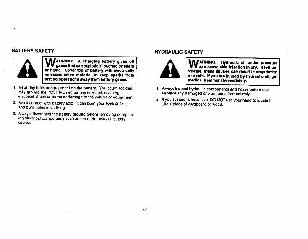
BATTERY SAFETY
'l. WARNING: A charging b8ery gives offg...1ha1 CCn explode If touched by .~rk
or flame. Cover top 01 baer whh eeectrlcallynon-conductlve matorlal to keep sp¡rk. fromtesting operations away from battery ga...
1, Never iay tools or equipment on the battery. You could acciden-tally ground the POSITtVE (+) battery terminal, resulting inelec1rical shock or burns O( damage to the vehicle or &ttuipment.
2. Avoid contact with battery acid. lt can burn yOU! eyes or skin,
and burn holes in clothing.
3. Always disconnect the battery ground before removing or replac~ing electrical components such as the motor relay or batterycables_
HYDRAULIC SAFETY
.
WARNING: Hydraulic ofJ under p,..ur.e.n cause akin InJection Injury. Jf tef un-1reated, these l"furJ.. can 'HuH In .mputlonor del1h. If you are InJured by hydrau1lc 011, get
medical treatment Immediately.
1. Always inspect hydraulic components and hoses before use.Replace any damaged or worn parts immediately.
2. tf you suspect a hose leaki DO NOT use your hand to locate it.Use a piece of cardboard or wood.
l.
32

NOTE: Batter or motor In por condition wil cau.. Inv.lldtest r.uhs.
B SOLENOID ISARMATIC(8 MARK iliaMALFUNCTION
1. Turn ignition (key) switch of vehicle to ON or ACCESSORY.
2. Turn ON/OFF Switch on solenoid control to ON,
A PUMP PRESSURE TEST
1. Discnnec lift chain and hoses to Hydra-Tiirn~ rams.
2. Install 2.00 PSI (minimum) gauge into female coupler on valvemanifold.
A WARNING: Keep well clear of 1he bladewhen It II being r.IMC, loered, or angled.Do not .tand ben the vehicle and blade ordirecly In front of bl.d.. If the blade hl1. you or
drop. on you, you. could be serIously Injured.
NOTE: If 'ndlca,or light on solenold control does not light.check 1 Hmp fus.ln fus. holder under dash or black groundwlr. betwn control and motor r.'.y.
3. Move control lever to RAISE. ANGLE RIGHT and ANGLE LEFT.
lF motor doe not run In .ny position. go to Relay TestC, page 34.
IF motor run. In one or two positions. go to Solenoid
ConHol Test D1 page 35.
IF motor runa In .11 three positions · go to Coil CartridgeTest Et page 36.
3. Move so'enoid control to ANGLE LEFT and read gauge.
4. tf pressure is 145(185 PSI~ pump pressure Is OK.
5, If pressure ÎS iow. remove pump. clean or replace fiiter and adjustpressure. Turn adiusting screw clockwise (CW) to ¡ncrease pres-
sure (1/4 turn eeuals approximately 225 PSt).
PressureRelief
Adluitment
SuctIonFitter
Fastener TroquePump Capscrews .. 175/185 In. Lbs.M010f Capscrews - 15/20 Ft. Lbs.
33

C RELAY TESTCONDiTION: Motor does not run with solenoid control in RAISE.ANGLE RtGHT or ANGLE LEFT. Battery has suffio¡ent charge to startvehicle engine. Vehicle ignition (key) switch and solenoid contro'ON/OFF switch are both ON. Red indicator ligh1 on control is glow-ing, indicat'ng that the 10 amp fuse looated under dash is OK.
1, Disconnect Hydra~ Tum(ß hoses and lift chain from lift channeL.
2, Chack afl electrical cables and connections including grounds.Clean and tighten if necessary.
A WARNING: Keep well cle.r of 1he bladewhen it Is beIng raised. towered, or .ngled.Do not sland between the vehicle and blade ordirectly in front of blade. 11 the blade hl1s you ordrops on you, you could be seriously injured.
3, Use a jumper wire to connect POSlnVE ( + ) termìnat of battery to.small terminal on motor relay with BROWN wíre attached. If
. motor runs, see Solenoíd Control Te$t~ D. page 35, and inspectharness from cOntrol to motor relay for broken Or damaged wires.It motor does not run...
A WARNING: A charging battery gives offgases 1hat can explode if touched by sparkor flame. Cover top of battery wi1h electricallynon-conductive material to keep sparks fromtesting operations away from battery oases,
4. Use jumper wire from s1ep 3 to connect NEGATIVE (-) terminalOf battery to small terminal on motor relay with BLACK wire at.tached. Use a second Jumper wire to repeat Step 3. If motorruns. repair bJack wire ground. If motor does not run..,
5. Use heavy jumper cables to by-pass Gump) the two large ter-minals on top of the motor relay. If motor runs. replace motorrelay. If motoi does not run,..
A WARNING: Always disconnec the batteryground before removing or replacingelectrical components such .. the motor relay,or battery cables.
6. Remove motor and check pump shaft rotation. If tight. repairor replace pump! if foose replace motor.
Reiiy..Solenoid
HydrauluicSystem(MotorRelay)
Black Wire..
Step 3
Brown Wire
34Step

D SOLENOID CONTROL TESTDO NOT use continuity testers for this test.
1, Discnnec the solenoid controf connecor. Turn oontro( ON/OFF
switch ON.
2. Attach 12-volt power supply to terminal shown in diagram.
3. In each position of the lever indicated in the chart below, use a
grounded cirouit tester light to test eaoh numbered terminaL. Thechart indicates the condItion of the circuit 1ester light.
Pin No.
Control Posllon 2 3 4 5 6
Neutral Of * Of Of OfRaise Of 'I
::::: O, '..Of:' OfAngle FUght :::,:01':.:.:
" ,.,:00:.: Of .-00. ..
Angle Left '::.::Ot'.' .. : ::Onn.. on ..00Lower Of . Of Of
... Of.n:,
* Indicator fight wil be on and the circuit tester light wil not be asbright.
**Stye 2 Control - tf oni move lever to ra'se. Retest angle right andJeft. If teste' I.ght Is now out) control is OK.
4. "lOd con1roo tes. OK. check harness for broken wÎres
and/or corroded connections.
If tes light Ii OFF when chart indicates it should be ON replaceprinted circuit board in control box.
IF tnt light Is ON when chart indlcates it should be OFF replacepr¡nted ccrcul1 board in oontrol box.
MM/0¡LlQQ r-it: 0~-
.wL~", J ~1 MfU*
I cmI: t ...:..Style 2 Control LabelStyle 1 Control Label
Step 3 IndicatorUght
ON/OFF Swftch
Jumper WireStep 2
2
3
Test. Lamp LeadStep 3
35

E COIL CARTRIDGE TEST1, Discnnect Hydra- Turn(Ö hoses and Jilt ohain from lift channel.
2. Move controJ lever to pOßition in chart and test coil cartridge as-sembly stem for good magnetio pull (energized) usrng a steelscrewdriver, Follow sequence shown in chart.
Valve
Position 2 Way 3 Way 4 Way
Raise No No y-Lower V.. No No
Right .No Yes No
Left -No V.. Vet.
Wire Connecion_.t Coils
2 Way vvite WWre3 Way Green 'Wre4 Way Blue WWreGround B'ack WWfe
* Style 2 Control - tf y0$, move lever to raise, pull should S10p.
lf coli activation MATCHES the above chan - proceed to Step 3.
If coli activation DOES NOT match chart M test for current at coilspade-to-harness connections on valve manifold.
tf current Is available - use a jumper wire to create a goodground at coil spade terminals with BLACK wires attached.
lf coli energizes. repair ground at coil spade or bodybolt in engine compartment.
lf coli not energized.. replace coiL.
lf current not available. test solenoid control per D1 page 35.
3. Re move coils frbm cartridges and remove cartridges from
manifold. Inspect cartridges for visible contamlna1ion ordamaged seals. Check for stuck spools us.ing a non-marring orscratching (plastic, aluminum or soft brass) probe to push springloaded spool.
NOTE: Uiing probe 10 move spol may .hear contmln--lonwhich w.. alfec1Jng spol movement.
lf stuck. replace cartridge.If 11.. .. install coil on stem. Bench-test using jumper wiresto energize coil while watching for spool movement.
If no movement sen .. replace caridge.If movement ieen . clean and oil cartrtdge. Reinstalloartlldge and coil. Note torques shown.
EXCESSIVE TORQUEWILL DAMAGE OR
AFFECT PERFORMANCEOF CARTRIDGE2 Way
Coli CartridgeValve
Test MagnetcPull Her.Step #2
Coil RetainIngNut Torque
4 to 5 Ft. Lb.
Cartridgeto M8nlfld
Torque20 Ft. Lb.
3 WayColi Cartridge
Valve
4 WayColi Car1rldge
Valve
Watch Here #3
Probe Here #3 -.36
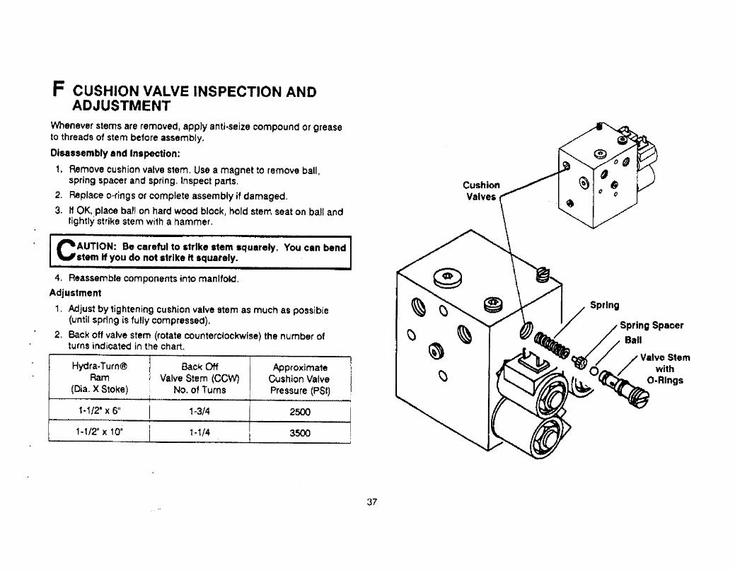
F CUSHION VALVE INSPECTION ANDADJUSTMENT
\'enever stems are removed! appJy antj.seize compound or grease
to threads of stem before assembly.
Disassembry and Inspetion:
i. Remove cushion valve stem, Use a magnet to remove ball ~spring spacer and spring. Inspect parts.
2. Replace o~fjngs or complete assembly if damaged.
3. If OK, plaoe ball on hard wood block, hold stem seat on ball andtightly strike stem with a hammer.
CAUTION: Be careful to strike stem squarely. You can bendstem If you do not strike It squarely.
4. Reassemble components into manifold.
Adjustment1. Adjust by tightening cushion valve stem as much as possible
(until spring is fully compressed),2. Back off valve stem (rotate counterclockwíse) the number of
turns indicated in the chart.
Hydra.. Turn~ Back Of Approximate,!i!
Ram Valve Stem (CC'' Cushlon Va~ve
(Dia. X Stoke) No. 01 Turns Pressure (PSr):
1~1I2" X 6"I
1 ~3/4 250
i -1/211 )( 1 Opti
1-1/4 350~i
Ii
I
, C)
~ ~ ~
\)
37

G' POPPET CHECK VALVE1. Remove o-ring boss plug. spring and poppet from top of valvEt
manifold.
2. Remove o-ring boss plug, spring and spool with o-ring from frontside of valve manifold (use needle-nose pJiers to remove spool).
3, lnspect parts, poppet seat and spool bore for damage or oon-tamination.
4, 'Install spool in bore. Spool must insert $moothly.
5: Install poppet. springs and o-ring boss plugs.
a-Ring :-808. Plug Y
Spring
Spol~i ~ ~ 0Spring "-.A ~
O-Ring , ~80118 PIU~
H QUILL ADJUSTMENTTo adjust blade drop speed:
1. Lower blade to ground before making adjustment.
2. SENSITlVE ADJUSTMENT - MAX, 1/8 TURN AT A TIME.
Turn quil IN (CIOck'ise) to slow drop speed.
Turn quHt OUT (counterc~ockw.se) to Increase drop speed.
NOTE: Turning qum too tar IN can .Iow ral.. time.
3. Stand c'ear of blade when checking adjustment.
A WARNING: Keep well clear of the bladewhen It Is being ralsedJ lowered. or .ngled.Do not stend between the vehicle and blede ordirecly In front of blade. If the blade hit you ordrops on you, you could be seriously inlured.
Quil
38

SOLENOID ISARMATICCIMARK Ilia PARTSDIAGRAM (Contd. on page 41.Parts List Notes:Parts list Abbréviatlon Key, Sé8 page 44.tndented parts are included in the assemblyunder which they are listed. Quanttties shownate included with the assembly.
~56"'¡.
19 61
18 1614 o 0- 6212 9- 63
51,
52,
53
- 41 54
~~
2
31
3
39

SOLENOID ISARMATICCI MARK Ilia PARTS LIST (Contd. on page 42)ITEM PART NO. QTY. DESCRIPTION ITEM PART NO. QTY. DESCRIPTION
1 49253 1 HYDRAUUC UNlT 1-1/2" SOL 350 34 49224 1 MANI FOLD ASSY SOL 3549280 1 HYDRAULIC UNiT 1-1/211 SOL 250 NVIO CARTRIDGES)
2 49252 1 SERVICE HOUSING KIT 1..1/2'1 SOL 49279 1 MANiFOLD A$SY SOL 2503 93166 2 5/16-i8X1.1!4 HXW TRT$ TV TR-3 tN/Q CARTRIDGES)4 92072 3 PLUG 1/4 NPTF HX SO (W/Auid Level Plug) 35 929 3 3/8-24 HX SO O-RING BOSS PLUG
92071 2 PLUG 1/8 N~TF HX SO (WIO Fluid Level Ptug) 30 92071 3 PLUG 1/8 NPTF HX SO5 49211 1 PUMP KIT DIE CAST 37 92072 1 PLUG 1/4 NPTF HX SO6 25620 1 Q.RfNG - '15 38 49225 i INLET CHECK VALVE KIT7 56185 1 SUCTION FILTER 39 49138 1 CUSHION VALVE REPAIR KIT-SET8 91101 2 1/4 PLAIN WASHER TV A STD ZP 40 49226 1 POPPET CHECK VALVE KIT9 91220 2 BELLEVILLE SPRING WASHER 41 56330 1 QUILL ASSV
.10 9025 2 5/16-18X2.1/4 HX CS G5 ZP 49257 1 BACK-UP/O-RING KIT - SOL11 25861 1 GASKET 44 56274 1 O-R!NG -013 l i NOT INCLUDED12 56133 1 MOTOR ASSY 4-1/2" 45 25730 2 O-RING - 012 W/49224/49265 or13 49262 1 BRUSH KIT - PA 56133 46 25731 2 O-RING.. 010 4921814927914 49084 1 MOTOR FLANGE BRG & SEAL 47 55371 2 a..RING - oo15 49014 1 01 L SEAL 48 25622 2 O-RING - 0016 91265 3 7/16 EX TOOTH LK WASHER ZP 49 56315 2 SACK-UP RING.. 00 PARBAK SPLIT17 9O 1 1/16-14X1-1/4 HX CS 05 ZP 51 49227 1 CARTRlDGE 20 WJJAM NUT18 90067 1 7/16p 14X1..1/2 HX CS G5 ZP 49258 1 SEAL KIT - CARTRtDGE 2019 55757 1 GROUND CLIP 52 49.28 1 CARTRIDGE 30 W/JAM NUT21 25944K 1 PACKING NUT i .1/2l1 53 49229 1 CARTRIDGE 40 W/JAM NUT22 25205K 1 PACKING SET WNN~peR 1.1/2" 49259 2 SEAL KIT - CARTRIDGE 30.33 & 4023 55137 1 WIPER RING.. 1-1/2u 54 49230 3 COil W/SPADE TERMINALS24 55136 1 PACKING SET 1.. i /211 55 56291 1 COVER ASSY25 91167 1 WASHER.. SPECIAL 56 90650 2 #B..18X1/2 SL HXWTFTS TV azp26 25202 1 PLUNGER 1-1/2" X 6" 57 91201 3 1/4 SP LK WASHER ZP27 56267 ' 1 SPLIT BEARING KIT 58 90083 3 1/4.20X3..1/4 HX CS G5 ZP29 92079 1 PLUG 3/8 NPTF SO 60 9038 1 3/8-16X3/4 HX CS G2 ZP31 25968K 1 BASE LUG W/#25618 O-RING 61 55984 1 GROUND CABLE 50u BLACK32 25618 i O.RING .216 62 91203 1 3/8 SP LK WASHER ZP33 49265 1 VALVE MANIFOLD ASSY SOL 3500 63 91413 1 3/8-16 HX NUT ZP
49278 1 VALVE MAN~FOLD ASSY SOL 2500
40

82
91
..ì~¡
uu.. tm392 t: ._..
JJ St 1 con1T:: i.be
\~.3 -'..(.,I~.. ,~!'0.", T"\' J ~ I. ·.. iIL P I~ l~",.:94 _J t: CD ...:-
~ -- 89 Sty 2 Conol Label
90
70
7V.75 .. 0
SOLENOID ISARMATICtI MARK IliaPARTS DIAGRAM
(Contd. from page 39)
~""103

SOLENOID ISARMATICCI MARK Ilia PARTS LIST (Contd. from page 40)ITEM PART NO. QTY. DESCRIPTION ITEM PART NO. QTY. DESCRIPTION
70 2565 1 BA TTEAY CABLE 60'~ RED 108 92275K 1 MALE ELBOW 1/4 NPTF X 90 SPl71 22511 1 BA TTEAY CABLE 2211 RED 109 25232K 2 QUICK COUPLER72 56134K 1 RELAY - SOLENOID HYDRAULIC SYSTEM 110 55020K 2 PRESSURE HOSe 1/4 n X 38'~73 91242 2 #10 SP LK WASHER SPO 111 92210K 1 STREET ELBOW 1/4 NPTF X 9074 9'402 2 #10-32 HX NUT ZP 112 92278K 1 MALE ELBOW 1/4 NPTF X 9015 9 t 202 2 5/16 SP LK WASH EA ZP 118 56102 2 RAM ASSY 1-' /2" X , 01176 92842 2 5/16-24 JAM NUT 5637 2 RAM ASSY 1.1/2" X 61180 9O2 2 1/4-20X3/4 HX CS G2 ZP 21 25944K 1 PACKING NUT 1.1/211
8 91101 2 1/4 PLAIN WASHER TV A STD ZP 22 25205K 1 PACKING SET W,wPER 1-1/2"81 91331 2 1/4.20 PT HX LK NUT NYIS ZP 23 55137 1 WIPER RING 1.1/2'.
.82 56285 1 .. SOLENOID CONTROL 24 55136 1 PACKING SET 1..1/21183 56283 1 SHIELD 25 91 \67 1 WASHER.. SPECIAL84 49231 1 '* BODY W/LASeL. LENS & SPRING (Styie 1) 119 56105 1 PLUNGER 1-1/2u X 10"
49286 1 .. BODY W/i-8EL & LENS (Style 2) 26 25202 1 PLUNGER 1-1/211 X 6/185 49232 1 * LEVER, SPRING & ACTUATOR KIT (Style 1) 27 56267 1 SPLIT BEARING KIT
49287 1 * LEVER. SPRING & ACTUATOR KIT (Style 2) 122 56104 1 CYLINDER 1..11211 x 10"86 55923 1 SPRING. CONICAL 5633 1 CYUNDER 1~ 1/T X 6.~87 49255 1 * PC BOARD ASSY (Style 1) 125 9038 4 #10X1 SL PN TFTS TV AS BZP
49¿84 i .. PC BOARD ASSY (Style 2) 126 91242 4 #10 SP LKWASHER SPO88 56199 1 BASE Parts Usted Btlow are Furnished in Appropriate Uf Mount Box.89 93153 2 #6-19X3/8 SL HX' TFT$ HI-LO 127 56 1 DASH BRACKET90 93154 2 -#8-18X5/8 SL HXW TFTS H I-LQ 128 561 i DASH BAACKET91 5630 1 CONTROL BRACKET 129 562 1 DASH BRACKET92 55381 1 CABLE CLAMP93 93157 5 #8-32X/8 SL HX' TCTS TV T BP94 91231 4 #8 SP LK WASHER BP99 9109 2 IF 10 PLAIN WASHER TV B NAR ZP
- Orders fQr tOmplete control asmblies \Mil be filled wittt S1le:2 control,.100 56307 1 HARNESS. CONTROL (10 Amp Fuse) CompOe-n, pars, wnere indicated, are not interchangeable betwrr tne tw
101 66130 2 RUBBER GROMMET styles. Order a.~c;otding 10 the label on the boy of your c:ontrol.
102 59114 1 SELF STRIP WIRE CONNECTORInder\ted pa", are included In the assembly under which they are lisl.c,
103 59223 5 CABLE TlE Quanti\ìM show at~ included with the M!!embly.
Pa.rts Ust Abbreviation Key, s" page 44.
42

EJ
l .1/20 32~~. ¡so~~.o~12
11~
SPORT/UTILITY PLOW PARTS DIAGRAM
~(Contd. on page 44)
14
41
13
~317 388 36~cr 37 36
~Q,~90 ~J3s128
~use ONLY GENUINE WESTERN(( REPLACEMENT PARTS
43
Parts Ust Notes:
tndented partsare Included in
the assemb Iyunder wh ich they
aré listed.
Quant.ties shownare inctuded with
the assmbly.
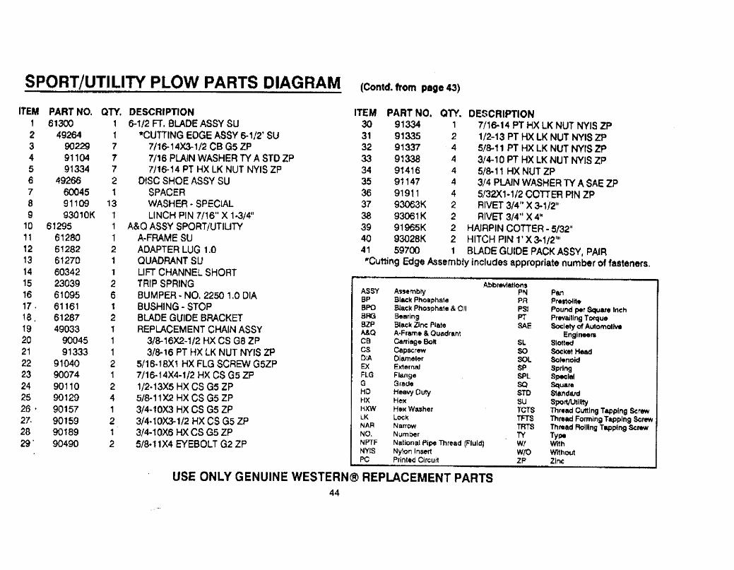
SPORT/UTILITY PLOW PARTS DIAGRAM (Contd. from page 43)
ITEM PART NO. QTY. DESCRIPTION1 6130 1 6-1/2 Fr. BLADE ASSY SU2 4926 1 *CUTTING EDGE ASSV 6-1/2' SU3 9022 7 7/16-14X31/2 CS Gs ZP4 91104 1 7/16 PLAlN WASHER TV A STO ZP5 91334 7 7/1&14 PT HX LK NUT NYIS ZP
Ô 49266 2 D~SC SHOE ASSY SU7 6045 1 SPACER8 91109 13 WASHER.. SPEClAL9 93010K 1 LINCH PIN 7116" X 1.3/4"
10 61295 1 A&Q ASSY SPORT/UTILITY11 61280 1 A.FRAME SU12 61282 2 ADAPTER LUG 1.013 61270 1 QUADRANT SU14 60342 1 LI FT CHANNEL SHORT15 23039 2 TRIP SF-RING
16 61095 6 BUMPER. NO. 2250 1.0 DIA17 . 61161 1 BUSHING - STOP18. 61267 2 BLADE GUIDE BRACKET19 49033 1 REPLACEMENT CHAIN ASSY20 9045 1 3/8-16X2.1/2 HX CS G8 ZP21 91333 1 3/8-' ô PT HX LK NUT NYIS ZP22 91040 2 5/16.18X1 HX FLG SCREW G5ZP23 90014 1 7/16-14X4-1/2 HX CS GS ZP24 90110 2 1/2-13X5 HX CS G5 ZP25 90129 4 5/8-11 X2 HX CS G5 ZP26 . 90 157 1 3/4~10X3 HX CS G5 ZP27. 90 159 2 3/4..10)(1/2 HX CS G5 ZP28 90 189 1 3/4-1 QX6 HX CS GS ZP29' 90490 2 5/8.11X4 EYEBOLT G2 ZP
ITEM PART NO. QTY. DESCRIPTION30 9133 i 1/16-14 PT HX LK NUT NYIS ZP31 9133 2 1/2-13 PT HX LK NUT NYIS ZP32 91337 4 5/s.11 PT HX LK NUT NYrS ZP33 9133 4 3/4-10 PT HX LK NUT NYJS ZP34 91418 4 5/8-11 HX NUT ZP35 91147 4 3/4 PlAN WASHER TV A SAE ZP36 91911 4 S/32X1.1/2 COTTER PIN ZP37 9303K 2 RIVET 3/4'. X 3-1/21138 9301 K 2 RIVET 3/4u X 4U39 91965K 2 HAIRPIN COTTeR - 5/321140 93028K 2 HITCH PIN l' X 3-1/211141 59700 1 BLADE GUrOE PACK ASSY, PAJR"Cut1ing Edge Assembly includes appropriate number of fasteners.
AbbreatlorsASSY Assembly PN PanBP Black PhoSlphate PR Prestooìte
BPO gla~k Phospha1. & eii PSI Pound per Sql,atlneh8F' Bearing PT Prevling TorueazP Blaçk Zinc Pla.te SA Soiet of AuomotivA&Q A£Frame & Quadrant EngineersCB Carriage Bo SL SlotedCS Capsc rew SO Soket HeaDlA Olame1er SOL Soi.noid8( Ëxxernal SP SpringFLG Flange SPL SJ:lafG Grade SO SquareHD He8\ Dut 8m StdarHX He)( SU Sporti IItyHXW HeJ( Washer rcr Thr.ad ClJlng Tapping ScrelK Lock TF Thre Forming Tapping Scr..NA~ Narrow TA Thtéad Roilng Tapping ScI'NO, Number TV Tyi-NPTF National Pcp, Thread (FluId) Wf Wi1hNYtS Nylon Insert WfO Wi1houPC Prirrted Cirçui1 ZP Zinc
USE ONLY GENUINE WESTERN~ REPLACEMENT PARTS44

STANDARD PLOW PARTS DIAGRAM
6 1 '1 Fe Standaad7 F t S t.::d.., d7.1'2 Fi Stand",rd
Blade Gu id(! S9700
L""k~i 9133/1
.~ ~ iCal')~Cr~.. 9015'1 .,....:... ~
i. "-...tj .,
__ E v~ tsòH 90493 Capscre"" 90 H,9..
Trip $prinçç 230J9
For Mljdl\.lT A FrameBOK No 60022 QrrivMt'niurr lift ChanneL SA734
OA
- For Shnn A Fiame80); No 60198 On.",Stirt L dt Cnannei 6m42
¡ A.F fameMeáii¡m 60030Sttrf 60202
"~\."'- Hairpin 91965... '- liiii:tt Pill9302a
For Meihurn A F fBn,f' 60030 OnlvCotte, Pin 919, 1
Rivet 93063
ORÍ"o' ShOff A F 'ame 60201 Only'
G foo..e Pin 92004Rivei 9306~
USE ONLY GENUINE WESTERN(( REPLACEMENT PARTS
45

PRO-PLOW PARTS DIAGRAM
81!cJe G LJlde 59700.-
Cl,lllrrg E09(' A~~'v ~lln Bolts and NuC¡ -9 Fi PAO PLOW. . 4925181'( Ft PAO PLOW. 490868 ft. PRO PLOw 49089., i,~ Ft PROPLOW.. 490aa
ClP5creW 90161'\
Locknul 91338 ~e~...... r" ,LOCi."II,H 91338
C¡¡PKrI;W 90l5'l-., ~.".,.. ~'\.. "~ ,. ,() ..;+( :- F or PRO PLOW Mei1lutfC¡¡imn¡.. 901t,9-- I A rr4'me 8011 ..0 603100"IV
~ i Medium lih C'unI111 !!134i ORL_ J:orPRQ.PLOW ShOrt
A F (oime 80), No 60315Sho- c L ,h Chitnntl 60341
¡~! ~-
Ht..\ly Duty Shoe ALs'y 4907 I
LinCh Pin93010
'i
('0 "'- HAil Pin 91985',- Hitch f'in 9JO==Fl
FOr PRO PLOW Meo,\)I'\ A F f~\(' 60374 Onl)'COHef Pirr 91911Rlwel 9306J
OR
Fo! PRO piOw $1'011 A tfli~e 60'0' Orr1yGrooiit' Pin 9~OO4H iii~t 9:.06!:
USE ONLY GENUINE WESTERN(8 REPLACEMENT PARTS
46

WESTERN PRODUCTS7777 NORTH 73AD STREET
P.O. BOX 23045MILWAUKEE, WISCONSIN 53223
M A CIVIStON OF DOUGLAS DYNAMiCS INC.
Western reserves the right under its Product Improvement Polioy to change construction or design de1aUs and furnlsh equip-ment when so altered without reference to ilustrations or specifications used herein, The foliowing are registered(( and un-registered ho Trade Marks of Douglas Dynamics. Inc~ WESTERN~t lSARMATICCI, HydrawTurn~, UniMount(â, Roll Action 'll iPRO-GUARD '''. Western and the vehicle manufacturer may require and/or recommend optional equipment for snow removaL.See Western.s instaUation instructions for details. Western offers a one year limited warfan1y for an snowplows and accessories.See separately printed page for this important information. .
Printed in U.S.A.