asme-b18.2.3.5m.pdf - OM GROUP
23
Металлопрокат и трубы по стандартам DIN, EN, ANSI, ASME, ASTM, ISO ОМ ГРУПП Поставляет в Россию металлопрокат по стандарту ASME_B18.2.3.5M Данная брошюра предоставлена для ознакомления! www.fedclicom.ru [email protected] +7(495)139-61-88
-
Upload
khangminh22 -
Category
Documents
-
view
2 -
download
0
Transcript of asme-b18.2.3.5m.pdf - OM GROUP

Металлопрокат и трубы постандартам
DIN, EN, ANSI, ASME, ASTM, ISO
ОМ ГРУПП Поставляет в Россию металлопрокат по стандарту
ASME_B18.2.3.5M
Данная брошюра предоставлена для ознакомления!
www.fedclicom.ru [email protected]+7(495)139-61-88

A M E R I C A N N A T I O N A L S T A N D A R D
Metric Hex Bolts
ANSI -A B.18.2.3.5M -.4979 Government Key Words: Bolt, Hex-Metric
REAFFIRMED 1995
FOR CURRENT COMMlnEE PERSONNEL PLEASE SEE ASME MANUAL AS-1 1
SECRETARIAT
SOCIETY OF AUTOMOTIVE ENGINEERS THE AMERICAN SOCIETY OF MECHANICAL ENGINEERS
P U B L I S H E D B Y
T H E A M E R I C A N S O C I E T Y O F M E C H A N I C A L E N G I N E E R S
United Engineering Center 345 East 47th Street New York, N. Y. 1001 7
Copyrighted m
aterial licensed to Stanford U
niversity by Thom
son Scientific (w
ww
.techstreet.com), dow
nloaded on Oct-05-2010 by S
tanford University U
ser. No further reproduction or distribution is perm
itted. Uncontrolled w
hen printed.

ANSI B18.2.3.5M-79 26 APRIL 1979
ACCEPTANCE NOTICE
This non-Government document was adopted on 26 April 1979 and is approved for use by the DoD and Federal Agencies. Metric hex bolts shall conform to this document and Appendix JJI, which establishes standard items for Government application. Appendix 111, Tabie 4 shall be used for item selection in accordance with the part numbering system and size information contained therein. The indicated industry group has furnished the clearances required by existing regulations. Copies of the document are stocked by DoD Single Stock Point, Naval Publications and Forms Center, Philadelphia, PA, 19120, for issue to DoD activities and Federal Agencies only. Contractors and industry groups must obtain copies directly from:
The American Society of Mechanical Engineers United Engineering Center, 345 E. 47th Street New York, NY IO01 7 or
The American National Standards Institvtc 1430 Broadway, New York, NY I0018
Title of Document: Bolt, Hex -- Mctric
ANSI Document No.: ANSI B18.2.3.5M-1979
Date of Specific Issue Adopted: 26 April 1979
Releasing Industry Group: The American Society of Mechanical Engineers
Custodians: Army - AR Navy - AS Air Force - 99
Review Activities: Army - AV, MI, ER Navy - MC
NSA - NS DLA - IS
Military Coordinating Activit) Army - ,AR .
(Project 5306-0620)
User Activities: Army - ME, AT Navy - SH
Civil Agencies: GSA-FSS
NOTICE: When reaffirmation, amendment, revision, or cancellation of this standard is initially proposed, the industry group responsible for this standard shall inform the Military Coordinating Activity of the proposed action and request their participation.
No part of this document may be reproduced in any form, in an electronic retrieval system or otherwise, without the prior written permission of the publisher.
Date of Issuance: August 31, 1979
CopyrightQ1979 by THE AMERICAN SOCIETY OF MECHANICAL ENGINEERS
All Rights Reserved Printed in U.S.A.
Copyrighted m
aterial licensed to Stanford U
niversity by Thom
son Scientific (w
ww
.techstreet.com), dow
nloaded on Oct-05-2010 by S
tanford University U
ser. No further reproduction or distribution is perm
itted. Uncontrolled w
hen printed.

ERRATA
to
ANSI B18.2.3.5M-1979 METRIC HEX BOLTS
Page 3, Note 18, change B1.13 to read B1.13M
Page 5, in the standard shall be replaced with the second page of this errata
Page 10, MATERIAL AND FINISH CODE, change to read:
A - Steel w/Cadmium Plating per QQP-416, Type 11, Class 3 (5.1pm Plating Thickness), Property Class 10.9.
B - Steel w/Zinc Plating per QQ-Z-325, Type 11, Class 3 (5.1pm Plating Thickness), Property Class 10.9.
THE AMERICAN SOCIETY OF MECHANICAL ENGINEERS 345 East 47 Street, New York, N.Y. 10017
May 1981
Copyrighted m
aterial licensed to Stanford U
niversity by Thom
son Scientific (w
ww
.techstreet.com), dow
nloaded on Oct-05-2010 by S
tanford University U
ser. No further reproduction or distribution is perm
itted. Uncontrolled w
hen printed.

AMERICAN NATIONAL STANDARD METRIC HEX BOLTS ANSI 618.2.3.5M-1979
NO TE
NOTE
17.3
14
SEE
PROPERfY CLASS AND MANU- FACTURER'S IDENTIFICATION SEE TO APPEAR ON TOP OF HEAD SEE NOTE 21
Table 1 Dimensions of Hex Bolts
t E K R -
ladius of
Fillet
B (Ref) D
Nominal Bolt
Dia and Thread Pitch
M5 x 0.8 M6 x 1 M8 x 1.25 M10 x 1.5
M12 x 1.75 M14 x 2 M16 x 2 M20 x 2.5 M24 x 3
M30 x 3.5 M36 x 4 M42 x 4.5 M48 x 5 M56 x 5.5
M64 x 6 M72 x 6 M80 x 6 M90 x 6 . M100 x 6
K1
Nrench,
Height ing
Da
Fillet rransi- tion Dia
- Max
5.7 6.8 9.2
11.2
13.7 15.7 17.7 22.4 26.4
33.4 39.4 45.4 52.0 62.0
70.0 78.0 86.0 96.0
107.0
Head Height
Lasic)
Bolt Lengths > 200
Thread Length
--
Width AtX-
Corners
Body Diameter
Width ACT- Flats Bolt
Lengths > 125ano
Q 200
22 24 28 32
36 40 44 52 60
72 84 96
108 124
140 156 172 192 212
17.3
Bolt Lengths < 125
- 16 18 22 26
30 34 38 46 54
66 78 90
102 -
- - - - -
- Max - 5.48 6.19 8.58
10.58
12.70 14.70 16.70 20.84 24 84
30.84 37 .OO 43 .OO 49.00 57.20
65.52 73.84 82.16 92.48
I 02.80 - -
- Min - 8.6:
10.8E 14.2C 17.55
19.8E 22.7s 26.1 i 32.95 39.55
50.55 60.7s 71.71 82.76 93.71
104.65 I 15.6C 126.54 143.07 I 59.6C - I - - 16.46 -
- Max - 9.24
11.55 15.01 18.48
20.78 24.25 27.7 1 34.64 41.57
53.12 63.51 75.06 86.60 98.15
09.70 21.24 32.79 50.1 1 67.43
E 17.32
- - - -
- Max
3.88 4.38 5.68 6.85
7.95 9.25
10.75 13.40 15.90
19.75 23.55 27.05 31.07 36.20
41.32 46.45 51.58 57.74 63.90
-
-
Min
2.4 2.8 3.7 4.5
5.2 6.2 7 .O 8.8
10.5
13.1 15.8 18.2 21 .o 24.5
28 .o 31.5 35.0 39.2 43.4
- Min
0.2 0.3 0.4 0.4
0.6 0.6 0.6 0.8 0.8
1 .o 1 .o 1.2 1.5 2 .o 2 .o 2.0 2.0 2 .o 2.5
- Min - 7.64 9.64
12.57 15.57
17.57 20.1 6 23.16 29.16 35.00
45 .OO 53.80 62.90 72.60 82.20
91.80 101.40 I1 1 .oo I 25.50 140.00 -
Min
3.35 3.85 5.10 6.1 7
7.24 8.51 9.68
12.12 14.56
17.92 21.62 25.03 28.93 33.80
38.68 43.55 48.42 54.26 60.1 0
- 4.52 8.00 5.52 10.00 7.42 13.00 9.42 16.00
1 1.30 18.00 13.30 21 .OO 15.30 24.00 19.16 30.00 23.16 36.00
29.16 46.00 35.00 55.00 4 1 .OO 65 .OO 47.00 75.00 54.80 85.00
62.80 95.00 70.80 105.00 78.80 115.00 88.60 130.00 98.60 1 45 .OO
~~
35 37 41 45
49 53 57 65 73
85 97
109 121 137
153 169 185 205 225
7
iz-l-77 8
4.5 I
M10x 1.5 10.58 9.42 15.00 14.57 26 32 45
"See Note 2.2 of General Data.
5
Copyrighted m
aterial licensed to Stanford U
niversity by Thom
son Scientific (w
ww
.techstreet.com), dow
nloaded on Oct-05-2010 by S
tanford University U
ser. No further reproduction or distribution is perm
itted. Uncontrolled w
hen printed.

MO 104E
Copyrighted m
aterial licensed to Stanford U
niversity by Thom
son Scientific (w
ww
.techstreet.com), dow
nloaded on Oct-05-2010 by S
tanford University U
ser. No further reproduction or distribution is perm
itted. Uncontrolled w
hen printed.

FOREWORD
American National Standards Committee B18 for the standardization of bolts, screws, nuts, rivets and similar fasteners was organized in March 1922, as Sectional Committee B18 under the aegis of the American Engineering Standards Committee (later the American Standards Association, then the United States of American Standards Institute and, as of October 6, 1969, the American National Standards Institute, Inc.), with the Society of Automotive Engineers and the American Society of Mechanical Engineers as joint sponsors. Subcommittee 2 was subsequently established and charged with the responsibility for technical content of standards covering wrench head bolts and nuts.
At its meeting on December 4, 1974, Committee B18 authorized preparation of a series of standards for metric fasteners. Subcommittee 2 was assigned responsibility for developing standards for metric hex bolts, screws and nuts.
At a meeting on September 22, 1976, Subcommittee 2 organized the contents of a standard covering eight different hex head screw and bolt products. Actual drafting was postponed until ISO/TC2 could reach final decisions relating to basic dimensions and characteristics of hex bolts, screws and nuts. At ISO/TC2 meetings held in April 1977, final actions were taken. Committee B18 affirmed the TC2 decisions at a meeting on June 29, 1977 and drafting of this standard was started.
In February 1978, Committee B18 established a cooperative program with the Department of Defense to draft American National Standards for metric fasteners in such a way that they could be used directly by the Government for procurement purposes. The Department of Defense requested that each of the eight products be covered in separate standards, and Subcommittee 2 accepted this approach at its meeting on June 27, 1978.
This standard was approved by letter ballot of Committee B18 on September 15, 1978, and was sub- sequently .approved by the secretariat and submitted to the American National Standards Institute for designation as an American National Standard. This was granted on April 26, 1979.
iii
Copyrighted m
aterial licensed to Stanford U
niversity by Thom
son Scientific (w
ww
.techstreet.com), dow
nloaded on Oct-05-2010 by S
tanford University U
ser. No further reproduction or distribution is perm
itted. Uncontrolled w
hen printed.

AMERICAN NATIONAL STANDARDS COMMITTEE B18 STANDARDIZATION OF BOLTS, NUTS, RIVETS, SCREWS,
WASHERS AND SIMILAR FASTENERS
OFFICERS
R. P. Trowbridge, Chairman J. 0. Levy, Vice-chairman H. G . Muenchinger, Vice-chairman Richard McGinnis, Secretary
COMMITTEE PERSONNEL
AMERICAN CHAIN ASSOCIATION L. E. Hampel, Moline Malleable Iron Company, St. Charles, Illinois
AMERICAN HARDWARE MANU1:ACTURERS ASSOCIATION Donald Wanek, Wrought Washer Manufacturing Company, Milwaukee, Wisconsin
AMERICAN INSTITUTE 01: INDUSTRIAL ENGINEERS R. T. Kelly, Hitchcock Publishing Company, Wheaton, Illinois
AMERICAN SOCIETY 01: AGRICULTURAL ENGINEERS E. R. friesth, Deere & Company, Moline, Illinois
AMERICAN SOCIETY 01.' MECHANICAL ENGINEERS, THE A. R. Machell, Jr., Xerox Corporation, Rochester, New York f. P. Tisch, Desert Hot Springs, California R. P. Trowbridge, GM Technical Center, Warren, Michigan C. R. Adams, Alternate, Newport News Shipbuilding & Dry Dock Company, Newport News, Virginia K. E. McCullough, Alternate, SPS Technologies, Jenkintown, Pennsylvania
ANTI-I'RICTION HIIARING MANU1:ACTUKER.S ASSOCIATION W. J. Derner, FMC Corporation, Indianapolis, Indiana
ENGINE MANUI'ACTURERS ASSOCIATION K. f. Naylor, Cunlmins Engine Company, Columbus, Indiana
I;ARM & INDUSTRIAL EQUIPMENT INSTITUTE E. R. friesth, Deere & Company, Moline, Illinois
H A N D TOOLS INSTITUTI: C. B. Ingersoll, J . H. Williams Company, Buffalo, New York
INDUSTRIAL 1,'ASTENERS INSTITUTE R. B. Belford, Industrial I'asteners Institute, Cleveland, Ohio A. R. Breed, The Lamson & Sessions Company, Cleveland, Ohio D. A. Garrison, Russell, Burdsall & Ward, Inc. Rock Falls, Illinois R. W Groover, Bethlehem Steel Company, Lebanon, Pennsylvania E. J. Heldman, Holo-Krome Company, West Hartford, Connecticut Jack Shugarf, Rockford Products Corporation, Rockford, Illinois D. P. Wagner, Illinois Tool Works, Inc., Elgin, Illinois 0. D. Wheeler, Armco Steel Corporation, Kansas City, Missouri N. W. Bellas, Alternate, Illinois Tool Works, lnc., Elgin, Illinois R. M. Harris, Alternate, Bethlehem Steel Corporation, Lebanon, Pennsylvania f. R. Ling, Alternate, Russell, Burdsall & Ward, Inc., Mentor, Ohio
METAL CUTTING TOOL INSTITUTE D. J. Emanuelli, Greenfield Tap & Die, Greenfield, Massachusetts
iv
Copyrighted m
aterial licensed to Stanford U
niversity by Thom
son Scientific (w
ww
.techstreet.com), dow
nloaded on Oct-05-2010 by S
tanford University U
ser. No further reproduction or distribution is perm
itted. Uncontrolled w
hen printed.

NATIONAL ELECTRICAL MANUFACTURERS ASSOCIATION J. 8. Levy, General Electric Company, Schenectady, New York F. f . Weingruber, Westinghouse Electric Corporation, Pittsburgh, Pennsylvania F. K. Kitzantides, Alternate, National Electrical Manufacturers Association, Washington, D.C.
NATIONAL ELEVATOR INDUSTRY, INC. R. J. Cummings, Otis Elevator Company, Mahwah, New Jersey
SOCIETY OF AUTOMOTIVE ENGINEERS H. W. Ellison, GM Corporation, Warren, Michigan S. E. Mallen, Ford Motor Company, Dearborn, Michigan R. S. Piofrowski, Mack Trucks, Inc., Allentown, Pennsylvania C. F. Schaening, GM Engineering Standards Section, Warren, Michigan R. R. Sjoberg, International Harvester Company, Hinsdale, Illinois D. W. Vial, Chrysler Corporation, Detroit, Michigan
SOCKET SCREW PRODUCTS BUREAU E. R. Carter, Jr., The Allen Manufacturing Company, Hartford, Connecticut Jack Trilling, Great Lakes Screw, Chicago, Illinois
TELEPHONE GROUP R. A. Agnew, Western Electric Company, Chicago, Illinois R. Morse, Bell Laboratories, Columbus, Ohio H. Haefeli, Alternate, Bell Laboratories, Columbus, Ohio
TUBULAR RIVET & MACHINE INSTITUTE J. G. Zerafsky, National Rivet & Manufacturing Company, Waupun, Wisconsin
U.S. DEPARTMENT OF THE AIR FORCE To be appointed
U.S. DEPARTMENT OF THE ARMY M. E. Taylor, U.S. Army Armament R & D Command, Dover, New Jersey Allen Herskovitz, Alternate, U.S. Army Armament R & D Command, Dover, New Jersey
U.S. DEPARTMENT OF DEFENSE N i Schwartz, Defense Industrial Supply Center, Philadelphia, Pennsylvania Lewis Pieninck, Alternate, Defense Industrial Supply Center, Philadelphia, Pennsylvania
U.S. DEPARTMENT OF THE NAVY J. R. Ruff, Department of the Navy, Washington, D.C. M. S. Orysh, Alternate, Department of the Navy, Philadelphia, Pennsylvania
U.S. MACHINE CAP WOOD & TAPPING SCREW BUREAUS S. C. Adamek, Pheoll Manufacturing Company, Chicago, Illinois R. M. Byrne, US. Screw Service Bureau, New York, New York T. J. Ferry, E.W. Ferry Screw Products Company, Inc., Cleveland, Ohio Casey Gordon, Parker-Kalon, Campbellsville, Kentucky H. G. Muenchinger, Continental Screw Company, New Bedford, Massachusetts K. D. Ringland, Parker-Kalon, USM Corporation, Campbellsville, Kentucky R. H. Seymour, Reed & Prince Manufacturing Company, Worcester, Massachusetts Louis Zanin, Elco Industries, Inc., Rockford, Illinois Paul f o y h o , Alternate, Harvey Hubbel, Inc., Bridgeport, Connecticut
INDIVIDUAL COMPANIES D. N. Badgley, Clark Equipment Company, Battle Creek, Michigan R. W. Bertoia, The Ohio Nut & Washer Company, Mingo Junction, Ohio E. D. Cowlin, Canton, Ohio J. E. Eaton, Jr., IBM Corporation, Boulder, Colorado J. F. Tornow, Microdot Inc., Troy, Michigan
INDIVIDUAL MEMBERS C. 0. Franklin, Valley Bolt Company, Marion, Iowa f . E. Graves, Fairfield, Connecticut
V
Copyrighted m
aterial licensed to Stanford U
niversity by Thom
son Scientific (w
ww
.techstreet.com), dow
nloaded on Oct-05-2010 by S
tanford University U
ser. No further reproduction or distribution is perm
itted. Uncontrolled w
hen printed.

PERSONNEL OF SUBCOMMITTEE NO. 2 - SQUARE AND HEX BOLTS AND NUTS
R. R. Sjoberg, Chairman, International Harvester Company, Hinsdale, Illinois R. B. Belford, Secretary, Industrial Fasteners Institute, Cleveland, Ohio S. C. Adamek, Pheoll Manufacturing Company, Chicago, Illinois D. N. Badgley, Clark Equipment Company, Battle Creek, Michigan A. G. Bausrerr, Federal Screw Works, Detroit, Michigan A. R. Breed, The Lamson & Sessions Company, Cleveland, Ohio R. M. Byme, U.S. Screw Service Bureau, New York, New York Art Clever, Deere & Company, Moline, Illinois M/: J. Derner, FMC Corporation, Indianapolis, Indiana D. A. Garrison, Russell, Burdsall& Ward, Inc., Rock €:ah, Illinois F. €. Graves, Fairfield, Connecticut R. M. Harris, Bethlehem Steel Corporation, Lebanon, Pennsylvania J. 6. Levy, General Electric Company, Schenectady, New York D. T. Lipari, Bell Telephone Laboratories, Inc., Columbus, Ohio A. R. Machell, Jr., Xerox Corporation, Rochester, New York K. E. McCullough, SPS Technologies, Jenkintown, Pennsylvania J. C. McMurray, Russell, Burdsall& Ward Inc., Mentor, Ohio H. G. Muenchinger, Continental Screw Company, New Bedford, Massachusetts J. F. Nagy, b'ord Motor Company, Dearborn, Michigan 1. M. Park, The Steel Company of Canada, Ltd., Hamilton, Ontario, Canada C. F. Schaening, General Motors Corporation, Warren, Michigan Lou Strang, Caterpillar Tractor Company, East Peoria, Illinois M. E. Taylor, U.S. Army Armament R & D Command, Dover, New Jersey R. P. Trowbridge, General Motors Corporation, Warren, Michigan P. A. Vacca, Defense Industrial Supply Center, Philadelphia, Pennsylvania F. F. Weingruber, Westinghouse Electric Corporation, Pittsburgh, Pennsylvania D. D. Wheeler, Armco Steel Corporation, Kansas City, Missouri Tony Nebesney, Alrernare, tMC Corporation, Indianapolis, Indiana L. Pieninck, Alfernafe, Defense Industrial Supply Center, Philadelphia, Pennsylvania
vi
Copyrighted m
aterial licensed to Stanford U
niversity by Thom
son Scientific (w
ww
.techstreet.com), dow
nloaded on Oct-05-2010 by S
tanford University U
ser. No further reproduction or distribution is perm
itted. Uncontrolled w
hen printed.

CONTENTS
Page GENERALDATA . . . . . . . . . . . . . . . . . . . . . . . . . . . . . . . . . . . . . . . . . . . . . . . . . . 1
TABLES 1 . Dimensions of Hex Bolts . . . . . . . . . . . . . . . . . . . . . . . . . . . . . . . . . . . . . . . . . . . . 5 2 . Dimensions of Reduced Body Diameter . . . . . . . . . . . . . . . . . . . . . . . . . . . . . . . . . . 6 3 . Length Tolerances . . . . . . . . . . . . . . . . . . . . . . . . . . . . . . . . . . . . . . . . . . . . . . . . 6
APPENDIXES Appendix I . Bolt Straightness. Referee Gage and Gaging Procedure . . . . . . . . . . . . . . . 7 Appendix I1 . Recommended Clearance Holes for Bolts . . . . . . . . . . . . . . . . . . . . . . . . 8 Appendix I11 . Government Standard Items and Part Numbering System . . . . . . . . . . . . . 9
vii
Copyrighted m
aterial licensed to Stanford U
niversity by Thom
son Scientific (w
ww
.techstreet.com), dow
nloaded on Oct-05-2010 by S
tanford University U
ser. No further reproduction or distribution is perm
itted. Uncontrolled w
hen printed.

ANSI 818.2.3.5M-1979
AMERICAN NATIONAL STANDARD
METRIC HEX BOLTS
GENERAL DATA
1. Scope
1.1 This standard covers the complete general and dimensional data for metric hex bolts recognized as “American National Standard.”
1.2 The inclusion of dimensional data in this stan- dard is not intended to imply that all of the sizes in conjunction with the various options described herein are stock production items. Consumers are re- quested to consult with manufacturers concerning lists of stock production hex bolts.
1.3 Hex bolts purchased for Government use shall conform to this standard, and additionally to the requirements of Appendix 111.
2. Comparison With I S 0 Standards
2.1 Hex bolts as presented in this standard have been coordinated, to the extent possible, with IS0 4016. The dimensional differences between this ANSI standard and IS0 4016 are few, relatively minor, and none will affect the functional inter- changeability of bolts manufactured to the require- ments of either.
The following functional characteristics of hex bolts in sizes M5 thru M36 are in agreement between this ANSI standard and IS0 4016:
Diameters and thread pitches (see 26) Body diameters Widths across flats (see 2.2) Head heights Thread lengths Thread dimensions Nominal lengths
2.2 At its meeting in Vama, May 1977, ISO/TC2 studied several technical reports analyzing design
considerations influencing determination of the best series of width across flats for hexagon bolts, screws and nuts. A primary technical objective was to achieve a logical ratio between under head (nut) bearing sur- face area (which determines the magnitude of the compressive stress on the bolted members) and the tensile stress area of the screw thread (which governs the clamping force that can be developed by tighten- ing the fastener.) Table 1 lists the sizes selected by ISO/TC2 to be IS0 standard.
M10 bolts with 15 mm width across flats are currently being produced and used in U.S.A. and many other countries of the world. This size, how- ever, is not an IS0 standard. Unless M10 bolts with 15 mm width across flats are specifically ordered, MI0 bolts with 16 mm width across flats shall be furnished.
2.3 Letter symbols designating dimensional charac- teristics are used in accord with those used in IS0 standards, except capitals have been used for data processing convenience instead of lower case letters used in IS0 standards.
3. Dimensions
3.1 All dimensions in this standard are in millimeters, unless stated otherwise.
3.2 Symbols specifying geometric characteristics are in accord with American National Standard, Dimen- sioning and Tolerancing, ANSI Y14.5-1973.
4. Availability. Hex bolts in sizes M5 thru M24 are standard only in lengths longer than 150 mm or 1 OD, whichever is shorter. When shorter lengths of these sizes are ordered, hex cap screws, in conformance with ANSI B18.2.3.1M, are normally supplied. Hex bolts in sizes M30 and larger are standard in all lengths, however, at manufacturer’s option, hex cap screws may be substituted for any diameter-length combination.
1
Copyrighted m
aterial licensed to Stanford U
niversity by Thom
son Scientific (w
ww
.techstreet.com), dow
nloaded on Oct-05-2010 by S
tanford University U
ser. No further reproduction or distribution is perm
itted. Uncontrolled w
hen printed.

AMERICAN NATIONAL STANDARD METRIC HEX BOLTS
5. Surface Condition. Bolts need not be finished on any surface except the threads.
6. Top of Head. The top of head shall be full form and chamfered or rounded. The diameter of the chamfer circle or the start of rounding shall be equal to the maximum width across flats within a tolerance of minus 15 percent.
7. Head Height. The head height is the distance, as measured parallel to the axis of the bolt, from the top of the head to the under head bearing surface.
8. Wrenching Height. The wrenching height is the distance, measured at a corner of the hex, from the plane of the bearing surface to the last plane of full formed hex, i.e., the plane closest to the top of head at which the width across corners of the hex is with- in its specified limits.
9. Corner Fill. The rounding due to lack of fill at the six corners of the head shall be reasonably uni- form.
IO. True Position of Head. The axis of the hex head shall be located at true position with respect to the axis of the bolt (determined over a distance under the head equal to one bolt diameter) within a tolerance zone of diameter equal to 6 percent of the specified maximum width across flats.
11. Bearing Surface. The bearing surface shall be reasonably flat. However, a die seam across the bear- ing face shall be permissible. Bearing surface shall be perpendicular to the axis of the body within a toler- ance of 3 deg for sizes M24 and smaller, and 2 deg for sizes larger than M24. Angularity measurement shall be taken at a location to avoid interference from a die seam.
12. Bolt Diameter
12.1 Bolts shall be furnished with full diameter body within the limits specified in Table 1 or shall be threaded to the head unless the purchaser specifies bolts with “reduced diameter body” (12.3).
12.2 There may be a reasonable swell, fin, or die seam on the body adjacent to the underside of head
ANSI B18.2.3.5M-1979
not to exceed the nominal bolt diameter by the following:
0.50 mm for M5 0.65 mm for M6 0.75 mm for M8 thru M14 1.25 mm for M16 1.50 mm for M20 thru M30 2.30 mm for M36 thru M48 3.00 mm for M56 thru M72 4.80 mm for M80 thru MlOO
12.3 Bolts may be obtained with “reduced diameter body” if so specified, however, bolts with nominal lengths shorter than 4D are not recommended. Where “reduced diameter body” is specified, the body di- ameter shall be within limits specified in Table 2. A shoulder under the head may be supplied at option of the manufacturer. When a shoulder is supplied, its diameter and length shall be as specified in Table 2.
13. Fillet. The fillet at junction of head and shank shall be a smooth concave curve within an envelope of R minimum and a radius tangent to the shank and to the underside of the head at a point equal to one- half of Da maximum from the axis to the bolt.
14. Length. The length of the bolt shall be measured parallel to the axis of the bolt from the underside of head to the extreme end of the shank. Tolerances for bolt lengths are given in Table 3.
15. Point. Bolts need not be pointed.
16. Straightness. Shanks of bolts shall be straight within a maximum camber of 0.006 mm/mm of bolt length for bolts having nominal lengths of 300 mm or shorter; and within 0.008 mm/mm of bolt length for bolts having nominal lengths over 300 mm to 600 111111. The referee gage and gaging procedure for check- ing bolt straightness is given in Appendix I.
17. Thread Length
17.1 The length of thread on bolts shall be con- trolled by the grip gaging length Lg max as set forth in 17.2 thru 17.4.
17.2 Grip Gaging Length, Lg max, is the distance measured parallel to the axis of bolt, from the under- side of the head to the face of a non-counterbored or non-countersunk standard GO thread ring gage assembled by hand as far as the thread will permit.
Copyrighted m
aterial licensed to Stanford U
niversity by Thom
son Scientific (w
ww
.techstreet.com), dow
nloaded on Oct-05-2010 by S
tanford University U
ser. No further reproduction or distribution is perm
itted. Uncontrolled w
hen printed.
AMERICAN NATIONAL STANDARD METRIC HEX BOLTS
The maximum grip gaging length, as calculated and rounded to one decimal place, for any bolt length shall be equal to the nominal bolt length, L, minus the basic thread length, B, as specified in Table 1, (Lg max = L - B). It represents the minimum design grip length of the bolt and shall be used as the crite- rion for inspection and for determining thread avail- ability when selecting bolt lengths even though usable threads may extend beyond this point.
All bolts of nominal lengths equal to or shorter than the sum of the basic thread length, B, plus a length of 2% thread pitches for sizes up to and in- cluding M24, and B plus 3% thread pitches for sizes larger than M24 shall be threaded full length. For bolts which are threaded full length, the distance from the bearing surface of the head to the face of a non-counterbored or non-countersunk standard GO thread ring gage assembled by hand as far as the thread will permit, shall not exceed the equivalent of 2% thread pitches for sizes up to and including M24, and 3% thread pitches for sizes larger than M24.
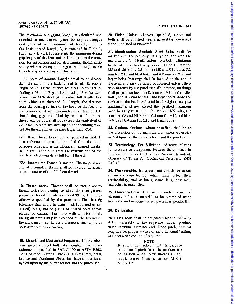
17.3 Basic Thread Length, B, as specified in Table 1, is a reference dimension, intended for calculation purposes only, and is the distance, measured parallel to the axis of the bolt, from the extreme end of the bolt to the last complete (full form) thread.
17.4 Incomplete Thread Diameter. The major diam- eter of incomplete thread shall not exceed the actual major diameter of the full form thread.
18. Thread Series. Threads shall be metric coarse thread series conforming to dimensions for general purpose external threads given in ANSI B1.13, unless otherwise specified by the purchaser. The class 6g tolerance shall apply to plain finish (unplated or un- coated) bolts, and to plated or coated bolts before plating or coating. For bolts with additive finish, the 6g diameters may be exceeded by the amount of the allowance, i.e., the basic diameters shall apply to bolts after plating or coating.
19. Material and Mechanical Properties. Unless other- wise specified, steel bolts shall conform to the re- quirements specified in SAE J1199 or ASTM F568. Bolts of other materials such as stainless steel, brass, bronze and aluminum alloys shall have properties as agreed upon by the manufacturer and the purchaser.
ANSI 818.2.3.5M-1979
20. Finish. Unless otherwise specified, screws and bolts shall be supplied with a natural (as processed) finish, unplated or uncoated.
21. Identification Symbols. Steel bolts shall be marked with the property class symbol and with the manufacturer’s identification symbol. Minimum height of property class symbols shall be 1.5 mm for M5 and M6 bolts, 2.3 mm for M8 and M10 bolts, 3.2 mm for M12 and M14 bolts, and 4.0 mm for M16 and larger bolts. Markings shall be located on the top of the head and may be raised or recessed unless other- wise ordered by the purchaser. When raised, markings shall project not less than O.lmm for M14 and smaller bolts, and 0.3 mm for M16 and larger bolts above the surface of the head, and total head height (head plus markings) shall not exceed the specified maximum head height plus 0.1 mm for M5 and M6 bolts, 0.2 mm for M8 and M10 bolts, 0.3 mm for M12 and M14 bolts, and 0.4 mm for M16 and larger bolts.
22. Options. Options, where specified, shall be at the discretion of the manufacturer unless otherwise agreed upon by the manufacturer and the purchaser.
23. Terminology. For definitions of terms relating to fasteners or component features thereof used in this standard, refer to American National Standard, Glossary of Terms for Mechanical Fasteners, ANSI B18.12.
24. Workmanship. Bolts shall not contain an excess of surface imperfections which might affect their serviceability, such as burrs, seams, laps, loose scale and other irregularities.
25. Clearance Holes. The recommended sizes of clearance holes in material to be assembled using hex bolts are the normal series given in Appendix 11.
26. Designation
26.1 Hex bolts shall be designated by the following data, preferably in the sequence shown: product name, nominal diameter and thread pitch, nominal length, steel property class or material identification, and protective coating, if required.
NOTE It is common practice in IS0 standards to omit thread pitch from the product size designation when screw threads are the metric coarse thread series, e.g., M10 is M10 x 1.5.
3
Copyrighted m
aterial licensed to Stanford U
niversity by Thom
son Scientific (w
ww
.techstreet.com), dow
nloaded on Oct-05-2010 by S
tanford University U
ser. No further reproduction or distribution is perm
itted. Uncontrolled w
hen printed.

AMERICAN NATIONAL STANDARD METRIC HEX BOLTS
Examples:
Hex bolt, M20 x 2.5 x 160, class 4.6, zinc plated Hex bolt, M36 x 4 x 80, silicon bronze
26.2 The government part numbering system for metric hex bolts is given in Appendix 111.
27. Referenced Standards
Copies of referenced ASTM standards' may be ob- tained from the American Society for Testing and
ANSI B18.2.3.5M-1979
Materials, 1916 Race Street, Philadelphia, Penn- sylvania 19 103.
Copies of referenced SAE standards may be ob- tained from the Society of Automotive Engineers, Inc., 400 Commonwealth Drive, Warrendale, Penn- sylvania 15096.
Copies of referenced IS0 standards may be ob- tained from the American National Standards Insti- tute, 1430 Broadway, New York, N.Y. 10018.
4
Copyrighted m
aterial licensed to Stanford U
niversity by Thom
son Scientific (w
ww
.techstreet.com), dow
nloaded on Oct-05-2010 by S
tanford University U
ser. No further reproduction or distribution is perm
itted. Uncontrolled w
hen printed.
AMERICAN NATIONAL STANDARD METRIC HEX BOLTS ANSI 818.2.3.5M-1979
k- B 4 SEE NOTE 17.3
/ L, --+.SEE NOTE 17.2 I PROPERTY CLASS AND MANU-
. FACTURER'S IDENTIFICATION I SEE NOTE 14
TO APPEAR ON TOP OF HEAD SEE NOTE 21
L
Table 1 Dimensions of Hex Bolts -I-
-
F
- -
i
13
X q T i -
D I D s I S E K Ki -
Vrench ing
Height
- Min
Da R B (Ref)
Fillet rransi- tion Dia
Thread Length (Basic) Width Across Corners
iadius of
Fillet
- Min
Nominal Body Width Across Flats Bolt Diameter
Head Height
iiJ-iF
Bolt Lengths ' 125and < 200
Bolt Lengths < 125
Bolt Lengths > 200
Dia and Thread Pitch
Max
.I5 x 0.8
10.58 ,110 x 1.5 8.58 .I8 x 1.25 6.19 .I6 x 1 5.48
.I12 x 1.75 12.70
.I1 4 x 2 14.70
.I16 x 2 16.70 A20 x 2.5 20.84 .I24 x 3 24 84
"130 x 3.5 30.84 J36 x 4 37 .OO 442 x 4.5 43.00 A48 x 5 49 .OO "156 x 5.5 57.20
A64 x 6 65.52 A72 x 6 73.84 480 x 6 82.16 A90 x 6 92.48 dl00 x 6 102.80
- Min - 7.64 9.64
12.57 15.57
17.57 20.16 23.1 6 29.16 35.00
45.00 53.80 62.90 72.60 82.20
91.80 101.40 I 11 .oo 125.50 140.00 -
- Min - 8.63
10.89 14.20 17.59
19.85 22.78 26.1 7 32.95 39.55
50.55 60.79 71.71 82.76 93.7 1
104.65 115.60 126.54 143.07 159.60 -
- Max - 9.24
11.55 15.01 18.48
20.78 24.25 27.71 34.64 41.57
53.12 63.51 75.06 86.60 98.15
09.70 21.24 32.79 50.1 1 67.43 -
Min I Max Max
2.4 2.8 3.7 4.5
5.2 6.2 7 .O 8.8
10.5
13.1 15.8 18.2 21 .o 24.5
28.0 31.5 35.0 39.2 43.4
5.7 6.8 9.2
11.2
0.2 0.3 0.4 0.4
0.6 0.6 0.6 0.8 0.8
1 .o 1 .o 1.2 1.5 2.0
2 .o 2.0 2.0 2.0 2.5
16 18 22 26
30 34 38 46 54
66 78 90
102 - - - - - -
22 24 28 32
36 40 44 52 60
72 84 96
108 124
140 156 1 72 192 212
35 37 41 45
49 53 57 65 73
85 97
109 121 1 37
153 169 185 205 225
4.52
16.00 9.42 13.00 7.42 10.00 5.52 8.00
11.30 18.00 13.30 21 .OO 15.30 24.00 19.16 30.00 23.16 36.00
29.16 46.00 35.00 55.00 41 .OO 65.00 47.00 75.00 54.80 85.00
62.80 95.00 70.80 105.00 78.80 11 5.00 88.60 130.00 98.60 145.00
3.58
6.17 6.85 5.10 5.68 3.55 4.38 3.35
7.95 7.24 9.25 8.51
10.75 9.68 13.40 12.12 15.90 14.56
19.75 17.92 23.55 21.72 27.05 25.03 31.07 28.93 36.20 33.80
41.32 38.68 46.45 43.55 51.58 48.42 57.74 54.26 63.90 60.10
13.7 15.7 17.7 22.4 26.4
33.4 39.4 45.4 52.0 62.0
70.0 72.0 86.0 96.0
107.0
6.9 7 8
4.5 - - 17.3 ;ee Notes
De Note 2.2 of General Data.
14.57 15.00 9.42 10.58 410 x 1.5
12
17.32 I 16.46 6.85 1 6.17 26 1 32 I 45
5
Copyrighted m
aterial licensed to Stanford U
niversity by Thom
son Scientific (w
ww
.techstreet.com), dow
nloaded on Oct-05-2010 by S
tanford University U
ser. No further reproduction or distribution is perm
itted. Uncontrolled w
hen printed.

AMERICAN NATIONAL STANDARD METRIC HEX BOLTS
Table 2 Dimensions of Reduced Body Diameters
Nominal Ds
Bolt Dia and Thread
Shoulder Diameter
Pitch h M5 x 0.8 M6 x 1 M8 x 1.25
M10 x 1.5 M12 x 1.75 M14 x 2
M16 x 2 M20 x 2.5 M24 x 3
5.48 6.48 8.58
10.58 12.70 14.70
16.70 20.84 24.84
4.52 5.52 7.42
9.42 1 1.30 13.30
15.30 19.16 23.16
Note: Shoulder is optional.
Body Diameter
Max I Min
7.26 7.04
8.86 10.95 10.68 12.77 12.50
14.77 14.50 18.49 18.16 22.13 21.80
ANSI 818.2.3.5M-1979
Lsh
Shoulder Length
Max I Min
8 .O 7 .O
9 .o 8 .O 11.0 10.0 13.0 12.0
Table 3 Length Tolerances I
Nominal Length M5 thru M8
to 50 mm over 50 to 80 mm
0.8
4.0 over 180 to 240 mm 2 .o over 120 to 180 mm 1.1 over 80 to 120 mm 1 .o
over 240 mm 5 .O
All tolerances are plus and minus
Nominal Bolt Diameter
M10 thru M16 I M20 and M24 I M30 and M36 I over M36
1.3 1.5 1.8 2.0 4.0 5 .O
2 .o 2.5 3 .O 3.5 4 .O 5 .O
3 .O 3.5 4.0 4.5 6.0 6 .O
~~
- 4.5 6 .O 6 .O 6.0 6 .O
6
Copyrighted m
aterial licensed to Stanford U
niversity by Thom
son Scientific (w
ww
.techstreet.com), dow
nloaded on Oct-05-2010 by S
tanford University U
ser. No further reproduction or distribution is perm
itted. Uncontrolled w
hen printed.

APPENDIX I
BOLT STRAIGHTNESS REFEREE GAGE AND GAGING PROCEDURE
The conformance of bolts to shank straightness or camber limitations set forth in the respective product standards shall be checked by using the gage illus- trated below in accordance with the following pro- cedure:
Allowable total camber on the product to be in- spected shall be calculated by multiplying the speci- fied permissible camber per mm of length by the product length expressed as a one place decimal. The total camber thus derived shall be added to the specified maximum body diameter exclusive of allowance for swell or fin under head and the ad-
justable rail of gage shall be adjusted to provide a parallel space between the rails equal to this distance by obtaining common readings on both micrometer heads. The adjustable rail shall then be locked in place by tightening securing screws.
The product shall then be inserted between rails, excluding from the gage any permissible length of swell or fillet under the head. The product shall be rotated by hand through full 360 deg. Any inter- ference occuring between the product and the gage which is sufficient to prevent rotation shall indicate excessive camber.
TYPICAL STRAIGHTNESS GAGE
y-- ADJUSTABLE
Y REVERSE READING MICROMETER HEADS 7
7
Copyrighted m
aterial licensed to Stanford U
niversity by Thom
son Scientific (w
ww
.techstreet.com), dow
nloaded on Oct-05-2010 by S
tanford University U
ser. No further reproduction or distribution is perm
itted. Uncontrolled w
hen printed.

APPENDIX I I
RECOMMENDED CLEARANCE HOLES FOR BOLTS
Clearance Holes for Bolts
T Nom Bol t Dia and
Thread Pitch
~5 X 0.8 M6 x 1 Ma x 1.25
M10 x 1.5 M12 x 1.75 M14 x 2 M16 x 2
M20 x 2.5 M24 x 3 M30 x 3.5 M36 x 4
M42 x 4.5 M48 x 5 M56 x 5.5 M64 x 6
M72 x 6 Ma0 x 6 M90 x 6 MlOO x 6
Dh-Clearance Hole Diameter, Basic
Close Clearance
5.3 6.4 a .4
10.5 13.0 15.0 17.0
21 .o
31 .O 37.0
43.0 50.0
25.0
58 .o 66.0
74.0 82.0 93.0
104.0
Notes:
preferred for general purpose applications, and should b e 1. Normal Clearance. Normal clearance hole sizes are
specified unless special design considerations dictate the need for either a close or loose clearance hole.
2. Close Clearance. Close clearance hole sizes should be specified only where conditions such as critical alignment of assembled parts,wall thicknessor other limitations necessitate use o f a minimal hole. When close clearance holes are speci- fied, special provision (e.g., countersinking) must be pro- vided at the bolt entry side t o permit proper seating of the bol t head.
Normal Clearance (Preferred)
5.5 6.6 9.0
11.0 13.5 15.5 17.5
22.0 26.0 33.0 39 .O
45.0 52.0 62.0 70.0
78.0 86.0 96.0
107.0
Loose Clearance
5 .a 7.0
10.0
12.0 14.5 16.5 18.5
24.0 28 .O 35.0 42 .O
48 .o 56.0 66.0 74.0
a2 .o 91 .o
101 .o 112.0
specified only for applications where maximum adjustment 3. Loose Clearance. Loose clearance hole sizes should be
capability between components being assembled is necessary.
ameters given in the table are minimum sizes. Recommended 4. Recommended Tolerances. The clearance hole di-
tolerances are plus 0.2 mm for bol t diameter M5; plus 0.3
ameters M20 thru M24; plus 0.5 mm for bo l t diameters M48 mm for diameters M6 thru M16; plus 0.4 mm for bo l t d i -
thru M72; and plus 0.6 mm for bol t diameters Ma0 thru M100.
8
Copyrighted m
aterial licensed to Stanford U
niversity by Thom
son Scientific (w
ww
.techstreet.com), dow
nloaded on Oct-05-2010 by S
tanford University U
ser. No further reproduction or distribution is perm
itted. Uncontrolled w
hen printed.

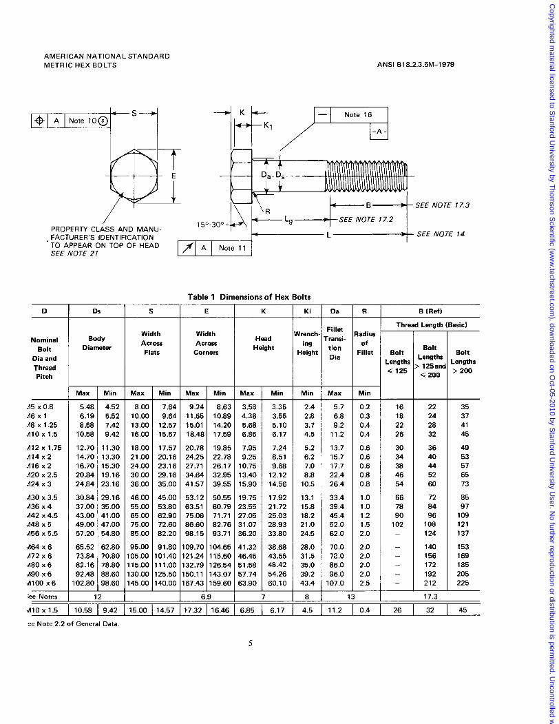
APPENDIX II I
Government Standard Items and Part Numbering System
Note
The Government encourages the general use of this appendix to achieve maximum parts standardization.
This appendix establishes the standard items for Government application selected from the possible variations of items within the scope of the standard and provides a part numbering system for identifica- tion and application in engineering documents.
The following variations are standard:
a. Diameter/Thread Pitch and Length Combina- tions-as specified in Table 4.
b. Material-Steel, Property Class 10.9. c. Finish-Cadmium plating or zinc plating as
coded in Part Numbering System. d. Special Features-drilled head or self-locking, as
specified. The part number shall consist of the following ele-
ment codes in the order shown:
a. Document Identifier - ANSI Standard Number less decimal points.
b. Material and Finish c. Nominal Diameter d. Nominal Length e. Special Features f. Special M10 Width Across Flats Size
Note
The Part Numbering System may also be used for non-standard diameter and length combinations.
Quality Assurance Provisions: Quality assurance provisions shall be in accordance with FF-S-85 Screw, ‘lap, Slotted and Hexagon Head.
Packaging: Packaging shall be in accordance with PPP-H-1581, Hardware (Fasteners and Related Items), Packaging and Packing for Shipment and Storage of.
9
Copyrighted m
aterial licensed to Stanford U
niversity by Thom
son Scientific (w
ww
.techstreet.com), dow
nloaded on Oct-05-2010 by S
tanford University U
ser. No further reproduction or distribution is perm
itted. Uncontrolled w
hen printed.

i 2 I-
; n a a n a t;; 2 a a
5 2 L 2
5 t;; $
z
n
- 5
H W
- I
0 I-
2 I I-
0 U
W o 3 -I U
E z W (3 W I I- o W (3 a a 3
8
f
z W I-
H Z a W > 0 (3 W I I- w c 0 z
W
cn
# 8
.- Y 0 -I
W 4 o
I I a m
'c 0
10
Copyrighted m
aterial licensed to Stanford U
niversity by Thom
son Scientific (w
ww
.techstreet.com), dow
nloaded on Oct-05-2010 by S
tanford University U
ser. No further reproduction or distribution is perm
itted. Uncontrolled w
hen printed.

-
omiru
l .m
nsth
-
8 10
12
14
16
20
25
30
35
40
45
50
55
60
65
70
75
80
100
90
110
120
1 30
140
150
160
200
180
220
240
260
300 -
Tabl
e 4
Met
ric H
ex B
olts
-Sta
ndar
d Si
zes
for G
over
nmen
t Use
Nom
inal
Dia
met
er an
d Th
read
Pitc
h
~5
~0
.8
M
90x6
1 M1
wx
6
M*0
x6
~
2x
6
Me
a5
M
56x5
.5
M42
x4.5
h
l36x
4 M
30x3
.5
MZO
x2.5
M
14
x3
M1
6x
2
M1
4r2
M
lZx
1.
75
MIO
X
1.5
~8~
1.25
ys
X 1
I 11 L1
AN
SI B
18.2
.3.1
M. M
ETR
IC H
EX
HE
AD
CAP
SC
REW
FO
R S
ELE
CTI
ON
WIT
HIN
TH
IS A
RE
A, US
E
SE
LEC
TIO
N
C
HIT
ER
IA,
APP
END
IX 1
11,
TAB
LE 8
. 1
I 10
110
1213
0
1415
0
1616
0 20
160
2416
0
0530
0 06
300
0830
0 10
300
1230
0 14
300
1630
0 20
300
2430
0 S
TAN
DA
RD
DIA
ME
TER
AN
D L
EN
GTH
CO
MB
INA
TIO
N
4209
0 'L
Gq 56
1 20
721 5
0
'Liz57
I 90
1 80
oozw
3030
0
3630
0 42
300
4830
0 56
300
6430
0
7230
0
8030
0
9030
0
0030
0
Copyrighted m
aterial licensed to Stanford U
niversity by Thom
son Scientific (w
ww
.techstreet.com), dow
nloaded on Oct-05-2010 by S
tanford University U
ser. No further reproduction or distribution is perm
itted. Uncontrolled w
hen printed.

MOO 104
Copyrighted m
aterial licensed to Stanford U
niversity by Thom
son Scientific (w
ww
.techstreet.com), dow
nloaded on Oct-05-2010 by S
tanford University U
ser. No further reproduction or distribution is perm
itted. Uncontrolled w
hen printed.