GENERAL CATALOGUE - ODE Solenoid Valves New Zealand
142
www.ode.it GENERAL CATALOGUE SOLENOID VALVES
-
Upload
khangminh22 -
Category
Documents
-
view
3 -
download
0
Transcript of GENERAL CATALOGUE - ODE Solenoid Valves New Zealand

www.ode.it
GENERAL CATALOGUE
SOLENOID VALVES
ODE S.r.l.Registered Office and Work Plant
23823 Colico (LC) Via Borgofrancone, 18, Zona IndustrialeCommercial and Administration Office
20090 Segrate (MI) Via Modigliani, 45tel. +39.02.715429 fax +39.02.715144
Com
pany
repo
rtin
g to
Man
agem
ent a
nd C
oord
inat
ion
of W
aver
ton
Inte
rnat
iona
l Lim
ited
- O
DE
rese
rves
the
right
to m
ake
any
chan
ges
with
out p
rior n
otic
e. E
d. 0
1/20
13 c
od. 3
0006
2 EN
G ©
OD
E s.
r.l. -
All
right
s re
serv
ed.


4
76
GENERAL INDEX
HIGH PRESSURE SOLENOID VALVES4 HIGH PRESSURE
AIR OPERATED VALVES4 21IA N.O.4 21IA N.C.4 21IH-5 N.C.
ACCESSORIES4 P9920874 P9922194 P990305-P992257
COILS4 BDA-BDF-BDV-BSA-BVA4 BDV08024C3 ÷ BDV08230A34 GDH-GDV4 GDV14024C3 ÷ GDV14230A34 LBA-LBF-LBV4 LBV05024A3 ÷ LBV05230A34 UDA-UDV4 TNA4X024D4 ÷ TNA10024C4
VIBRATION PUMPS4 PX504 TP4004 TP5004 TP6004 TP760
TECHNOPOLYMER RANGE
STAINLESS STEEL RANGE
ACCESSORIES RANGE
CERTIFICATIONS
page. 99 “ 100-101
page. 103 “ 104-105 “ 106-107 “ 108-109
page. 111 “ 112 “ 113 “ 114-115
page. 117 “ 118-119 “ 120 “ 121 “ 122 “ 123 “ 124 “ 125 “ 126-127
page. 129 “ 130 “ 131 “ 132 “ 133 “ 134
page. 136
page. 138
page. 140
page. 142
GENERAL INDEX
HOW TO READ THE CATALOGUE
MACROSECTOR INDEX
ABOUT US
WHERE WE ARE
GENERAL SALES CONDITIONS
GENERAL INFORMATIONABOUT SOLENOID VALVES FUNCTIONING
GENERAL PURPOSE SOLENOID VALVES4 21A N.C./N.O.4 21A PROP N.C.4 21A-PW N.C./N.O.4 21A16 N.C.4 21H-EN N.C.4 21HT-HN-HF N.C./N.O.4 21IH-IN N.C.4 21J N.C.4 21L N.C./N.O.4 21M N.O.4 21T N.C.4 21W N.C./N.O.4 21X N.C.4 21YW-YN N.C./N.O.4 31A N.C./N.O.4 31A N.C.4 31JN N.C.4 31L N.C.4 512 N.C.4 4743 N.C.
TECNOPOLYMER SOLENOID VALVES4 21D-K N.C.4 21JP N.C.4 21SBG N.C.4 31JP N.C
PINCH SOLENOID VALVES4 21Z N.C./N.O.4 31Z N.C.
EXPLOSION PROOF SOLENOID VALVES ATEX4 21A Ex N.C./N.O.4 21IH Ex N.C.4 21L Ex N.C.4 21W Ex N.C./N.O.4 21X Ex N.C.4 31A2 Ex N.C.4 31L Ex N.C.
page. 4
page. 8-11
page. 12
page. 13
page. 14-15
page. 16-22
page. 25 “ 26-27 “ 28-29 “ 30-31 “ 32-33 “ 34-35 “ 36-37 “ 38-39 “ 40-41 “ 42-43 “ 44-45 “ 46-47 “ 48-49 “ 50-51 “ 52-53 “ 54-55 “ 56-57 “ 58-59 “ 60-61 “ 62-63 “ 64-65
page. 67 “ 68-69 “ 70-71 “ 72-73 “ 74-75
page. 76 “ 78-79 “ 80-81
page. 83 “ 84-85 “ 86-87 “ 88-89 “ 90-91 “ 92-93 “ 94-95 “ 96-97
HOW TO READ THE CATALOGUE
GENERAL INDEX - page 6-7
In order to identify more easily the product of your interest, we have developed two different indices that will help you in the search.

5
98
MACROSECTOR INDEX
4 UDA-UDV4 TNA4X024D4 ÷ TNA10024C4
WATER4 21A N.C./N.O.4 21A PROP N.C.4 21A-PW N.C./N.O.4 21H-EN N.C.4 21HT-HN-HF N.C./N.O.4 21IH-IN N.C.4 21J N.C.4 21L N.C./N.O.4 21T N.C.4 21W N.C./N.O.4 21X N.C.4 31A N.C./N.O.4 31A N.C.4 31JN N.C.4 31L N.C.4 512 N.C.4 4743 N.C.4 21D-K N.C.4 21JP N.C.4 21SBG N.C.4 31JP N.C4 21Z N.C./N.O.4 31Z N.C. 4 21A Ex N.C./N.O.4 21IH Ex N.C.4 21L Ex N.C.4 21W Ex N.C./N.O.4 21X Ex N.C.4 31A2 Ex N.C.4 31L Ex N.C.4 HIGH PRESSURE4 21IA N.O.4 21IA N.C.4 21IH-5 N.C.4 P9920874 P990305-P9922574 BDA-BDF-BDV-BSA-BVA4 BDV08024C3 ÷ BDV08230A34 GDH-GDV4 GDV14024C3 ÷ GDV14230A34 LBA-LBF-LBV4 LBV05024A3 ÷ LBV05230A34 UDA-UDV4 TNA4X024D4 ÷ TNA10024C44 PX504 TP4004 TP5004 TP6004 TP760
“ 125 “ 126-127
page 26-27 “ 28-29 “ 30-31 “ 34-35 “ 36-37 “ 38-39 “ 40-41 “ 42-43 “ 46-47 “ 48-49 “ 50-51 “ 54-55 “ 56-57 “ 58-59 “ 60-61 “ 62-63 “ 64-65 “ 68-69 “ 70-71 “ 72-73 “ 74-75 “ 78-79 “ 80-81 “ 84-85 “ 86-87 “ 88-89 “ 90-91 “ 92-93 “ 94-95 “ 96-97 “ 100-101 “ 104-105 “ 106-107 “ 108-109 “ 112 “ 114-115 “ 118-119 “ 120 “ 121 “ 122 “ 123 “ 124 “ 125 “ 126-127 “ 130 “ 131 “ 132 “ 133 “ 134
MACROSECTOR INDEX
CHEMICAL4 21IH-IN N.C.4 21L N.C./N.O.4 21X N.C.4 31L N.C.4 4743 N.C.4 21SBG N.C.4 31JP N.C4 21Z N.C./N.O.4 31Z N.C.4 21A Ex N.C./N.O.4 21IH Ex N.C.4 21L Ex N.C.4 21W Ex N.C./N.O.4 31A2 Ex N.C.4 31L Ex N.C.4 21IA N.O.4 21IA N.C.4 21IH-5 N.C.4 P9922194 P990305-P9922574 BDA-BDF-BDV-BSA-BVA4 BDV08024C3 ÷ BDV08230A34 GDH-GDV4 GDV14024C3 ÷ GDV14230A34 LBA-LBF-LBV4 LBV05024A3 ÷ LBV05230A34 UDA-UDV4 TNA4X024D4 ÷ TNA10024C4
STEAM4 21A N.C./N.O.4 21A PROP N.C.4 21A16 N.C.4 21IH-IN N.C.4 21J N.C.4 21L N.C./N.O.4 21X N.C.4 21YW-YN N.C./N.O.4 31A N.C./N.O.4 31A N.C.4 31JN N.C.4 31L N.C.4 21JP N.C.4 21SBG N.C.4 31JP N.C4 21Z N.C./N.O.4 31Z N.C.4 21X Ex N.C.4 21IA N.O.4 21IA N.C.4 21IH-5 N.C.4 P990305-P9922574 BDA-BDF-BDV-BSA-BVA4 BDV08024C3 ÷ BDV08230A34 GDH-GDV4 GDV14024C3 ÷ GDV14230A34 LBA-LBF-LBV4 LBV05024A3 ÷ LBV05230A3
page 38-39 “ 42-43 “ 50-51 “ 60-61 “ 64-65 “ 72-73 “ 74-75 “ 78-79 “ 80-81 “ 84-85 “ 86-87 “ 88-89 “ 90-91 “ 94-95 “ 96-97 “ 104-105 “ 106-107 “ 108-109 “ 113 “ 114-115 “ 118-119 “ 120 “ 121 “ 122 “ 123 “ 124 “ 125 “ 126-127
page 26-27 “ 28-29 “ 32-33 “ 38-39 “ 40-41 “ 42-43 “ 50-51 “ 52-53 “ 54-55 “ 56-57 “ 58-59 “ 60-61 “ 70-71 “ 72-73 “ 74-75 “ 78-79 “ 80-81 “ 92-93 “ 104-105 “ 106-107 “ 108-109 “ 114-115 “ 118-119 “ 120 “ 121 “ 122 “ 123 “ 124
TWO DIFFERENTINDEXES FORYOUR PRODUCTSRESEARCH.
MACROSECTOR INDEX - page 8-11

6
GENERAL INDEX
HOW TO READ THE CATALOGUE
MACROSECTOR INDEX
ABOUT US
WHERE WE ARE
GENERAL SALES CONDITIONS
GENERAL INFORMATIONABOUT SOLENOID VALVES FUNCTIONING
GENERAL PURPOSE SOLENOID VALVES4 21A N.C./N.O.4 21A PROP N.C.4 21A-PW N.C./N.O.4 21A16 N.C.4 21H-EN N.C.4 21HT-HN-HF N.C./N.O.4 21IH-IN N.C.4 21J N.C.4 21L N.C./N.O.4 21M N.O.4 21T N.C.4 21W N.C./N.O.4 21X N.C.4 21YW-YN N.C./N.O.4 31A N.C./N.O.4 31A N.C.4 31JN N.C.4 31L N.C.4 512 N.C.4 4743 N.C.
TECNOPOLYMER SOLENOID VALVES4 21D-K N.C.4 21JP N.C.4 21SBG N.C.4 31JP N.C
PINCH SOLENOID VALVES4 21Z N.C./N.O.4 31Z N.C.
EXPLOSION PROOF SOLENOID VALVES ATEX4 21A Ex N.C./N.O.4 21IH Ex N.C.4 21L Ex N.C.4 21W Ex N.C./N.O.4 21X Ex N.C.4 31A2 Ex N.C.4 31L Ex N.C.
page. 4
page. 8-11
page. 12
page. 13
page. 14-15
page. 16-22
page. 25 “ 26-27 “ 28-29 “ 30-31 “ 32-33 “ 34-35 “ 36-37 “ 38-39 “ 40-41 “ 42-43 “ 44-45 “ 46-47 “ 48-49 “ 50-51 “ 52-53 “ 54-55 “ 56-57 “ 58-59 “ 60-61 “ 62-63 “ 64-65
page. 67 “ 68-69 “ 70-71 “ 72-73 “ 74-75
page. 76 “ 78-79 “ 80-81
page. 83 “ 84-85 “ 86-87 “ 88-89 “ 90-91 “ 92-93 “ 94-95 “ 96-97

7
GENERAL INDEX
HIGH PRESSURE SOLENOID VALVES4 HIGH PRESSURE
AIR OPERATED VALVES4 21IA N.O.4 21IA N.C.4 21IH-5 N.C.
ACCESSORIES4 P9920874 P9922194 P990305-P992257
COILS4 BDA-BDF-BDV-BSA-BVA4 BDV08024C3 ÷ BDV08230A34 GDH-GDV4 GDV14024C3 ÷ GDV14230A34 LBA-LBF-LBV4 LBV05024A3 ÷ LBV05230A34 UDA-UDV4 TNA4X024D4 ÷ TNA10024C4
VIBRATION PUMPS4 PX504 TP4004 TP5004 TP6004 TP760
TECHNOPOLYMER RANGE
STAINLESS STEEL RANGE
ACCESSORIES RANGE
CERTIFICATIONS
page. 99 “ 100-101
page. 103 “ 104-105 “ 106-107 “ 108-109
page. 111 “ 112 “ 113 “ 114-115
page. 117 “ 118-119 “ 120 “ 121 “ 122 “ 123 “ 124 “ 125 “ 126-127
page. 129 “ 130 “ 131 “ 132 “ 133 “ 134
page. 136
page. 138
page. 140
page. 142

8
MACROSECTOR INDEX
CHEMICAL4 21IH-IN N.C.4 21L N.C./N.O.4 21X N.C.4 31L N.C.4 4743 N.C.4 21SBG N.C.4 31JP N.C4 21Z N.C./N.O.4 31Z N.C.4 21A Ex N.C./N.O.4 21IH Ex N.C.4 21L Ex N.C.4 21W Ex N.C./N.O.4 31A2 Ex N.C.4 31L Ex N.C.4 21IA N.O.4 21IA N.C.4 21IH-5 N.C.4 P9922194 P990305-P9922574 BDA-BDF-BDV-BSA-BVA4 BDV08024C3 ÷ BDV08230A34 GDH-GDV4 GDV14024C3 ÷ GDV14230A34 LBA-LBF-LBV4 LBV05024A3 ÷ LBV05230A34 UDA-UDV4 TNA4X024D4 ÷ TNA10024C4
STEAM4 21A N.C./N.O.4 21A PROP N.C.4 21A16 N.C.4 21IH-IN N.C.4 21J N.C.4 21L N.C./N.O.4 21X N.C.4 21YW-YN N.C./N.O.4 31A N.C./N.O.4 31A N.C.4 31JN N.C.4 31L N.C.4 21JP N.C.4 21SBG N.C.4 31JP N.C4 21Z N.C./N.O.4 31Z N.C.4 21X Ex N.C.4 21IA N.O.4 21IA N.C.4 21IH-5 N.C.4 P990305-P9922574 BDA-BDF-BDV-BSA-BVA4 BDV08024C3 ÷ BDV08230A34 GDH-GDV4 GDV14024C3 ÷ GDV14230A34 LBA-LBF-LBV4 LBV05024A3 ÷ LBV05230A3
page 38-39 “ 42-43 “ 50-51 “ 60-61 “ 64-65 “ 72-73 “ 74-75 “ 78-79 “ 80-81 “ 84-85 “ 86-87 “ 88-89 “ 90-91 “ 94-95 “ 96-97 “ 104-105 “ 106-107 “ 108-109 “ 113 “ 114-115 “ 118-119 “ 120 “ 121 “ 122 “ 123 “ 124 “ 125 “ 126-127
page 26-27 “ 28-29 “ 32-33 “ 38-39 “ 40-41 “ 42-43 “ 50-51 “ 52-53 “ 54-55 “ 56-57 “ 58-59 “ 60-61 “ 70-71 “ 72-73 “ 74-75 “ 78-79 “ 80-81 “ 92-93 “ 104-105 “ 106-107 “ 108-109 “ 114-115 “ 118-119 “ 120 “ 121 “ 122 “ 123 “ 124

9
MACROSECTOR INDEX
4 UDA-UDV4 TNA4X024D4 ÷ TNA10024C4
WATER4 21A N.C./N.O.4 21A PROP N.C.4 21A-PW N.C./N.O.4 21H-EN N.C.4 21HT-HN-HF N.C./N.O.4 21IH-IN N.C.4 21J N.C.4 21L N.C./N.O.4 21T N.C.4 21W N.C./N.O.4 21X N.C.4 31A N.C./N.O.4 31A N.C.4 31JN N.C.4 31L N.C.4 512 N.C.4 4743 N.C.4 21D-K N.C.4 21JP N.C.4 21SBG N.C.4 31JP N.C4 21Z N.C./N.O.4 31Z N.C. 4 21A Ex N.C./N.O.4 21IH Ex N.C.4 21L Ex N.C.4 21W Ex N.C./N.O.4 21X Ex N.C.4 31A2 Ex N.C.4 31L Ex N.C.4 HIGH PRESSURE4 21IA N.O.4 21IA N.C.4 21IH-5 N.C.4 P9920874 P990305-P9922574 BDA-BDF-BDV-BSA-BVA4 BDV08024C3 ÷ BDV08230A34 GDH-GDV4 GDV14024C3 ÷ GDV14230A34 LBA-LBF-LBV4 LBV05024A3 ÷ LBV05230A34 UDA-UDV4 TNA4X024D4 ÷ TNA10024C44 PX504 TP4004 TP5004 TP6004 TP760
“ 125 “ 126-127
page 26-27 “ 28-29 “ 30-31 “ 34-35 “ 36-37 “ 38-39 “ 40-41 “ 42-43 “ 46-47 “ 48-49 “ 50-51 “ 54-55 “ 56-57 “ 58-59 “ 60-61 “ 62-63 “ 64-65 “ 68-69 “ 70-71 “ 72-73 “ 74-75 “ 78-79 “ 80-81 “ 84-85 “ 86-87 “ 88-89 “ 90-91 “ 92-93 “ 94-95 “ 96-97 “ 100-101 “ 104-105 “ 106-107 “ 108-109 “ 112 “ 114-115 “ 118-119 “ 120 “ 121 “ 122 “ 123 “ 124 “ 125 “ 126-127 “ 130 “ 131 “ 132 “ 133 “ 134

10
MACROSECTOR INDEX
AIR4 21A N.C./N.O.4 21A PROP N.C.4 21A-PW N.C./N.O.4 21H-EN N.C.4 21HT-HN-HF N.C./N.O.4 21IH-IN N.C.4 21J N.C.4 21L N.C./N.O.4 21M N.O.4 21T N.C.4 21W N.C./N.O.4 21X N.C.4 31A N.C./N.O.4 31A N.C.4 31JN N.C.4 31L N.C.4 512 N.C.4 21JP N.C.4 21SBG N.C.4 31JP N.C4 21Z N.C./N.O.4 31Z N.C.4 21A Ex N.C./N.O.4 21IH Ex N.C.4 21L Ex N.C.4 21W Ex N.C./N.O.4 31A2 Ex N.C.4 31L Ex N.C.4 HIGH PRESSURE4 21IA N.O.4 21IA N.C.4 21IH-5 N.C.4 P9920874 P990305-P9922574 BDA-BDF-BDV-BSA-BVA4 BDV08024C3 ÷ BDV08230A34 GDH-GDV4 GDV14024C3 ÷ GDV14230A34 LBA-LBF-LBV4 LBV05024A3 ÷ LBV05230A34 UDA-UDV
VENDING4 21A N.C./N.O.4 21A PROP N.C.4 21IH-IN N.C.4 21J N.C.4 21L N.C./N.O.4 31A N.C./N.O.4 31A N.C.4 31JN N.C.4 31L N.C.4 21D-K N.C.4 21JP N.C.4 21SBG N.C.4 31JP N.C4 21Z N.C./N.O.4 31Z N.C.
page 26-27 “ 28-29 “ 30-31 “ 34-35 “ 36-37 “ 38-39 “ 40-41 “ 42-43 “ 44-45 “ 46-47 “ 48-49 “ 50-51 “ 54-55 “ 56-57 “ 58-59 “ 60-61 “ 62-63 “ 70-71 “ 72-73 “ 74-75 “ 78-79 “ 80-81 “ 84-85 “ 86-87 “ 88-89 “ 90-91 “ 94-95 “ 96-97 “ 100-101 “ 104-105 “ 106-107 “ 108-109 “ 112 “ 114-115 “ 118-119 “ 120 “ 121 “ 122 “ 123 “ 124 “ 125
page 26-27 “ 28-29 “ 38-39 “ 40-41 “ 42-43 “ 54-55 “ 56-57 “ 58-59 “ 60-61 “ 68-69 “ 70-71 “ 72-73 “ 74-75 “ 78-79 “ 80-81

11
MACROSECTOR INDEX
4 P990305-P9922574 BDA-BDF-BDV-BSA-BVA4 BDV08024C3 ÷ BDV08230A34 GDH-GDV4 GDV14024C3 ÷ GDV14230A34 LBA-LBF-LBV4 LBV05024A3 ÷ LBV05230A34 UDA-UDV4 PX504 TP4004 TP5004 TP6004 TP760
“ 114-115 “ 118-119 “ 120 “ 121 “ 122 “ 123 “ 124 “ 125 “ 130 “ 131 “ 132 “ 133 “ 134

12
ABOUT US
ODE is a leading company since 1960 in designing and manufacturing a complete line of solenoid valves and pumps able to satisfy to all our customers needs.
ODE is headquartered in Milan, Italy, with the manufacturing plant in Colico,close to the Swiss border.In 2010 we celebrated 50 years of design and manufacturing excellencein the solenoid valves industry.Our general purpose and customized valves are designed to operate very effectively in the coffee machines industry.
ODE’s products are manufactured, assembled and tested in our factory in Italyusing lean manufacturing techniques driven by Six Sigma quality practices.
ODE quality is based on the platform of process control grantingthe elimination of variances, a computerized integrated system able to guarantee the conformity of products, the recording each productionstep able to ensure effective data analysis as well as a completeand efficient traceability of both components and finished products,always maintaining standards of high competitiveness in the marketplace.
All the above allowed Ode to obtain the ISO 9001, UL, CSA, UR, VDE, NSF, PEDand ATEX certifications.

13
THE CONCEPTOF QUALITY HAS ALWAYS BEENPART OF ODE CULTURE AND MISSION.
ODE IN THE WORLD Argentina, Australia, Austria, Belgium, Brazil, Bulgaria, Chile, China, Croatia, Czech Republic, Denmark, Egypt, El Salvador, Finland, France,Germany, Greece, Guatemala, Hungary, India, Iran, Israel, Italy, Ivory Coast, Japan, Korea, Lebanon, Lithuania, Malaysia, Mexico, Morocco, Netherlands,New Zealand, Norway, Pakistan, Perù, Poland, Portugal, Romania, Russia, San Marino, Saudi Arabia, Serbia and Montenegro, Singapore, Slovakia, Slovenia,Spain, South Africa, Sweden, Switzerland, Syria, Taiwan, Tunisia, Turkey, Ukraine, United Arab Emirates, United Kingdom, Usa, Vietnam.
WHERE WE ARE

14
GENERAL SALES CONDITIONS
ATTENTION
Read carefully the conditions of sale before purchase
1 Subject The present conditions represent all current and future contractual relations for ODE product suppliers.
2 Contract Preparation2.1 The supply contract is concluded with the emission of the order confirmation on behalf of ODE. If ODE does not accept part or all of the order, modifications to the order required will be sent in writing to the Client within five working days from the date of receipt. After 24 hours without receiving notification of objection from the client, the modifications introduced by ODE will be deemed to be accepted.
3 Exclusions3.1 System design, installation of supplied devices, specific tests, instructional courses, assistance3.2 In addition, taxes, exportation fees and any other additional expenses are not included in the price, unless otherwise specified and agreed upon by all parties.
4 Technical data, design and documents supplied4.1 The information provided by ODE in catalogues, brochures, technical sheets or other illustrative documentation are only suggestive. This information is not binding unless specifically mentioned in the delivery.4.2 ODE reserves the right to make modifications at any moment without warning in order to make technical and constructive improvements.4.3 The client is expressly committed to not use images, technical information and other aspects of the delivery for various reasons other than those mentioned in the contract, they remain property of ODE and the client cannot previde them to third parties or reproduce them without written authorization.
5 Transport, packaging and consignment5.1 Transport: for the transportation the goods, if not otherwise stipulated, are packaged in standard packaging, the client bears all risks.5.2 Packaging: the packaging is not received by return to sender, unless agreed upon in writing among parties.5.3 Consignment: the date of consignment and postage are not legally binding; in any circumstance, ODE is not liable for lateness of consignment: a) lf the client does not supply the details or materials necessary for the delivery before the deadline or requests variations to be made to a package or is delayed in answering requests deadline or requests variations to be made to a package or is delayed in answering requests of design approval. b) lf caused by reasons other than the good will and diligence of ODE, including lateness of subcontractors, that blocks or causes the excessively late consignment according to established terms. Not including the specifications of article 13 below, regarding products not consigned to the client for reasons for which they are liable or otherwise, for causes outside the responsibility of ODE, the Client will accept the risks an d expenses for custody.5.4 Claims: no claims will be accepted if sent after eight days from the receipt of goods, unless otherwise agreed amongst parties.5.5 lf the client is not up to date with payments, ODE has the right to delay all consignments until the client has paid the sum owed.5.6 lf the ODE consignment is delayed where parties have previously agreed that ODE must pay a penalty fee for late consignment, the client cannot ask for compensation for damages caused above the penalty fee agreed upon.
6 Conformity and tests6.1 A multilingual copy of the “Certificate of Conformity” regarding catalogue information, indicating the information of clients order and of the ODE delivery note is available if requested by the client within the delivery contract.6.2 Special deliveries according to client requests are to be agreed upon by parties and be executed at the expense of the client in the ODE headquarters.
7 Prices, discounts and reparations7.1 The prices indicated on the price list do not include VAT (value added tax)7.2 Price variability: ODE reserves the right to vary prices without any warning; the price lists are not binding. The prices can also vary if the quantities ordered are reduced or requested to be delivered in a shorter time period than previously stipulated.7.3 The offers emitted by ODE are referred to a specific consignment, they are not applicable for other deliveries of the same products if not otherwise specified in the supply contract.7.4 All the discounts given by ODE are valid for thirty days from the date of proposal. Unless other wise agreed by all parties, discounts are irrevocable and expire after thirty days automatically according to article 1329 of the ltalian Commercial Code. 7.5 Minimum Order: Direct orders below the following net sums are not accepted € 300,00 for OEM clients € 300,00 for distributors and reseliers price supplements will be applied to orders under this sum.
8 Payment8.1 Unless otherwise stipulated payments must be made by the Client within the indicated terms of the invoice through the chosen credit institution.8.2 For administrative reasons no rounding off will be accepted.

15
8.3 lf the client’s payment is late he’s bound to pay the interest according to the Italia n Legislative Decree N” 231/2002, without necessity of statutory notice from ODE S.r.l., with calculation deriving from the above mentioned Decree and based on the currently applied interest rate as per the mentioned Decree. ODE has the right to request compensation for major damage caused and the termination of the contract according to the following article 13.8.4 Any future disputes that occur between the parties do not exempt the Client from the obligation to observe the terms and conditions of payment.
9 Returns9.1 Returns are not accepted if not authorized beforehand by our personnel, as a result of a written request from the Client. The transportation costs will remain at the client expense. The value of the goods returned will be reduced by a percentage to be established, never below 20%, to account for costs incurred during testing and returning products to storage.9.2 Similarly returns for repair or substitution of products must be previously authorized by our personnel through a written notice by the client regarding product defects; if the defects are covered by the guarantee, article 10 is applied.
10 Warranty10.1 ODE guarantees the conformity of products supplied, the products are free from defects in materials a nel/or workmanship and they conform to all indications in the catalogue.10.2 The warranty lasts 12 months beginning from the date of products consignment and for products or components substituted under warranty, from the day they are consigned to the client.10.3 Within this period the client may denounce defects through relative non conformance documentation according to the terms of article 9.2, ODE is committed without obligation- within a reasonable time period in relation to the product of disputes- to repair or substitute the products or parts of the product that have proved dysfunctional free of charge; the client is obliged to send the dysfunctional products in an appropriate package, unless otherwise stipulated. lf ODE substitutes the products before receiving the dysfunctional products, the client is then obliged to return the dysfunctional products or articles to ODE unless otherwise stlpulated referring to the reparation/substitution bill in the returned consignment note guaranteed byODE. ODE reserves the right to charge the client for costs of products substituted and/or transportation fees if necessary, following testing, for products that are not covered by the guarantee.10.4 The substitution and reparations are undertaken by ex-works; the costs and risks of transport of dysfunctional products are the responsibility of the client.10.5 ODE excludes any warranty on products mounted or utilized incorrectly or noncompliantly to indications in the catalogue or in the instructions for usage and maintenance; in addition the warranty terminates if the products are stored incorrectly or exposed to insufficient maintenance or have been modified without ODE authorization.
11 Suppliers responslbility11.1 ODE is thereafter responsible for the correct functioning of products supplied regarding characteristics and performance as indicated by the catalogue and/or relative documentation.11.2 ODE is not responsible in any way for defects in machine operations or systems caused by the client or third parties to ODE products, even if these products have been mounted or connected following diagrams and illustrations produced by ODE.11.3 The client cannot request compensation for indirect damage, lost profits or loss of production caused by the product, nor can they receive compensation above the value of the products supplied, with the exception of any aspects covered by the Consumer Code (Legislative decree 6 September 2005, number 206), and by article 1229 of the ltalian commerciai Code.
12 Retention of title12.1 The products supplied remain the property of ODE until the client pays the agreed in full. lf the client does not pay, ODE reserves the right to request the restitution of the goods by the client, in this case they lose their right of ownership.
13 Resolutive clause expressed and resolutive conditions13.1 The supply contract will terminate in accordance with article 1456 of the ltalian Commercial Code following a simplified declaration written by ODE exercising the right of the resolutive clause expressed, if the client: a) omits or delays payments owed is late or does not consign the products within the terms stipulated by the previous article 5. b) does not observe the obligations of copyright as stipulated in the previous article 4.13.2 The contract will terminate if the client is in liquidation.
14 Applicable laws14.1 The supply contracts, including those for overseas clients, are regulated by the present general conditions and the ltalian Law.
15 Court of Jurisdiction15.1 The Court of Jurisdlction of Milan is competent if any dispute regarding the execution, interpretation, validity, resolution and termination of supply contracts between parties filed by the client; if the action is filed by ODE any Court according to the law is competent in addition to the Court of Jurisdiction of Milan.
GENERAL SALES CONDITIONS

16
GENERAL INFORMATION ABOUT ODE SOLENOID VALVES FUNCTIONING
1.1 2/2 way normally closed direct acting solenoid valves
Main components: body with main orifice, complete armature tube + complete plunger (normally closed kit), coil.
Functioning:2/2 way normally closed direct acting solenoid valves have an inlet pipe and an outlet pipe.The plunger, on which a sealing gasket is mounted, provides directly for opening and closingthe main orifice. When the coil is not energized, the plunger is in such a position as to closethe orifice thus preventing the fluid flow.When the coil is energized the plunger moves to such a position as to open the orifice,permitting fluid flow.
Notes:in this solenoid valve range, a pressure increase causes the force required to open the valve:if the pressure difference between inlet and outlet is greater than the maximum value forwhich the solenoid valve has been designed, the latter may not open even with the coilenergized.
1.2 2/2 way normally open direct acting solenoid valves
Main components: body with main orifice, complete armature tube + plunger + rod + gasket holder assembly (normally open kit), coil.
Functioning:2/2 way normally open direct acting solenoid valves have an inlet pipe and a outlet pipe. Theplunger, acting on the gasket holder by means of a rod, provides for opening and closing thesolenoid valve. When the coil is not energized the gasket holder, under the action of a spring,is kept in such a position that the orifice is open, permitting fluid flow.When the coil is energized the plunger moves downwards and, by means of the rod, pushesthe gasket holder into a position that closes the orifice, preventing fluid flow.
Notes:In this solenoid valve range an increase in pressure causes an increase in the force requiredto open the valve: if the pressure difference between inlet and outlet is greater than themaximum value for which the valve has been designed, the latter may not reopen even withthe coil deactivated.

17
1.3 2/2 way normally closed solenoid valves with pilot control
Main components: body with main orifice, cover, diaphragm (or piston) assembly, complete armature tube, + complete plunger (normally closed kit), coil.
Functioning:2/2 way normally closed solenoid valves with pilot control have an inlet pipe and a outletpipe. The main orifice, in the body, is opened by the effect of an unbalance in pressurebetween the upper and lower surfaces of a diaphragm (or piston): when the coil is notenergized there is fluid under pressure in the chamber above the diaphragm while beneaththe diaphragm there is pressure only in the area external to the main orifice: thus theresultant of the forces on the diaphragm is such as to push it and close the main orifice. Whenthe coil is energized, movement of the plunger, on which a gasket is mounted, cause the pilotorifice opening and the chamber discharging above the diaphragm: the pressure unbalancemoves the diaphragm which opens the main orifice.
Notes:In this solenoid valves range there must be a minimum pressure difference between the inletand the outlet pipes to ensure the correct solenoid valve functioning. However, an excessivepressure difference between inlet and outlet, as with 2 way normally closed direct actingsolenoid valves, causes an increase in the force required to open the pilot orifice, so if thispressure difference is greater than the maximum value for which the solenoid valve has beendesigned, the latter may not open even when the coil is energized.For a correct operation of the solenoid valve, and to avoid a quick wear of the diaphragm, it is advisable that, once starting the valve closing, the actual flow isn’t higher than the Kv (i.e.: flow rate through the valve with a pressure loss of 1 bar).For this reason, should the inlet pressure when the valve is open, be higher than 1 bar, itis not advisable the use of the valve itself with free outlet, i.e. without an outlet restrictionbringing the pressure drop to the value of 1 bar.Moreover, particular attention must be paid in designing the hydraulic circuit to the problemof water hammering which could cause overpressures such as to lacerate the diaphragm ordamage other parts of the solenoid valve.
1.4 2 way normally open solenoid valves with pilot control
Main components: body with main orifice, cover, diaphragm (or piston) assembly, complete armature tube + plunger + gasket holder + gasket (normally open kit), coil.
Functioning:2 way normally open solenoid valves with pilot control have an inlet and an outlet pipe.These solenoid valves functioning, as regards movement of the diaphragm, identical to that of2 way normally closed solenoid valves with pilot control except that in place of the normallyclosed kit a normally open kit is mounted to open and close the pilot orifice. So in this casewith the coil energized the pilot orifice is closed and the diaphragm therefore in such aposition as to close the main orifice, whereas with the coil energized the pilot orifice is open,thus causing the main orifice to open.
Notes:In this solenoid valves range there must be a minimum pressure difference between the inletand outlet pipes to ensure correct solenoid valve functioning.However, an excessive pressure difference between inlet and outlet, as with 2 way normallyopen direct acting solenoid valves, causes an increase in the force required to open the pilotorifice, so if this pressure difference is greater than the maximum value for which the solenoidvalve has been designed, the latter may not reopen even when the coil is not energized.For a correct operation of the solenoid valve, and to avoid a quick wear of the diaphragm, it is advisable that, once starting the valve closing, the actual flow isn’t higher than the Kv (i.e.: flow rate through the valve with a pressure loss of 1 bar).For this reason, the inlet pressure when the valve is open, should be higher than 1 bar,it is not advisable the use of the valve itself with free outlet, i.e. without an outlet restrictionbringing the pressure drop to the value of 1 bar.Moreover, particular attention must be paid in designing the hydraulic circuit to the problemof water hammering which could cause overpressures such as to lacerate the diaphragm ordamage other parts of the solenoid valve.
GENERAL INFORMATION

18
1.5 2/2 way normally closed combined operation solenoid valves
Main components: body with main orifice, cover, diaphragm (or piston) assembly, complete armature tube + complete plunger, coil.
Functioning:2 way normally closed combined operation solenoid valves have an inlet and an outlet pipe.The main orifice opening, which is in the body, comes about by an unbalance is pressurebetween the upper and lower surfaces of a diaphragm (or piston) together with direct actionof the plunger which is fixed to the diaphragm. Functioning is substantially similar to that ofsolenoid valves with pilot control as regards diaphragm movement except that even withsmall pressure differences between inlet and outlet, functioning is ensured by the direct actionof the plunger on the diaphragm. So, also in this case, when the coil is not energized there isfluid under pressure in the chamber above the diaphragm while beneath the diaphragm thereis pressure only in the area external to the main orifice: therefore the resultant of the forceson the diaphragm is such as to push it to close the main orifice. When the coil is energized,movement of the plunger, on which a gasket is mounted, opens an orifice on the completediaphragm (pilot orifice) and discharges the chamber above the diaphragm. At the same timethe plunger exercises direct force on the diaphragm, aiding its opening. The sum of this forceand the pressures unbalance on the two sides of the diaphragm causes the diaphragm tomove and open the main orifice.
Notes:In this solenoid valves range there must not be a minimum pressure difference between theinlet and outlet pipes to ensure correct solenoid valve functioning.However, an excessive pressure difference between inlet and outlet, as with 2 way normallyclosed direct acting solenoid valves, causes an increase on the force required to open the pilotorifice, so if this pressure difference is greater than the maximum value for which the solenoidvalve has been designed, the latter may not open even when the coil is energized.For a correct operation of the solenoid valve, and to avoid a quick wear of the diaphragm, itis advisable that, once starting the valve closing, the actual flow isn’t higher than the Kv (i.e.:flow rate through the valve with a pressure loss of 1 bar).For this reason, the inlet pressure when the valve is open, should be higher than 1 bar, it isnot advisable the valve itself use with free outlet, i.e. without an outlet restriction bringing thepressure drop to the value of 1 bar.Moreover, particular attention must be paid in designing the hydraulic circuit to the problemof water hammering which could cause overpressures such as to lacerate the diaphragm ordamage other solenoid valve parts.
1.6 2/2 way normally open combined operation solenoid valves
Main components: body with main orifice, cover, diaphragm (or piston) assembly, complete armature tube + complete plunger, coil.
Functioning:2 way normally open combined operation solenoid valves have an inlet pipe and a outletpipe. 2 way normally open functioning is substantially similar to that of solenoid valves mixedactuated normally closed. The difference is basically in the piloting kit. Instead of a normallyclosed solenoid operator, it is mounted a normally open kit. In this case when the coilis powered the piloting orifice will be closed and the main seat will keep close the valve.The opposite happen when the coil is not powered and the main seat remains open allowingthe fluid flow.
Notes:In this family of solenoid valves there must not be a minimum pressure difference betweenthe inlet and outlet pipes to ensure correct functioning of the solenoid valve.However, an excessive pressure difference between inlet and outlet, as with 2 way normallyclosed direct acting solenoid valves, causes an increase in the force required to open the pilotorifice, so if this pressure difference is greater than the maximum value for which the solenoidvalve has been designed, the latter may not open even when the coil is energized.For a correct operation of the solenoid valve, and to avoid a quick wear of the diaphragm,it is advisable that, once starting the valve closing, the actual flow isn’t higher than the Kv(i.e.: flow rate through the valve with a pressure loss of 1 bar).For this reason, should the inlet pressure when the valve is open, be higher than 1 bar,it is not advisable the use of the valve itself with free outlet, i.e. without an outlet restrictionbringing the pressure drop to the value of 1 bar.Moreover, particular attention must be paidin designing the hydraulic circuit to the problem of water hammering which could causeoverpressures such as to lacerate the diaphragm or damage other parts of the solenoid valve.
GENERAL INFORMATION ABOUT ODE SOLENOID VALVES FUNCTIONING

19
1.6 Proportional direct acting solenoid valves
Main components: body with main orifice, complete armature tube + adjustment screws + plunger + gasket, coil.
Functioning:Proportional direct acting solenoid valves have an inlet and an outlet pipe. The plunger, onwhich a sealing gasket is mounted, provides directly for opening and closing the main orificeof the solenoid valve.Unlike 2 way normally closed solenoid valves which have only two states, open and closed,a proportional solenoid valve, in function of the current run in the coil, can open partially.The solenoid valve can be set with the adjustment screws in such a way that, with the coil notenergized, a perfect seal at maximum project pressure is guaranteed.For clarification regarding methods used for energising and controlling this type of solenoidvalve, see the functioning scheme for these valves in this section.It is important to note that proportional solenoid valves are always operated by Direct Current(DC).
Notes:On these valves, unlike the other models, the fluid shall enter into the valve so to passthrough the main orifice from the lower side towards the higher one.In this solenoid valves range an increase in pressure, as 3 way solenoid valves, causes areduction in the pressure required to open the valve: if the pressure difference between inletand outlet is greater than the maximum value for which the solenoid valve has been tared,the latter may open even when the coil is not energized. Proportional solenoid valves aretared individually, at the moment of installation and inspection testing, with the adjustmentscrews in the fixed core: any modification of this taring may make the valve work in adifferent way with regard to the data shown on the label.
2.1 3/2 way normally closed direct acting solenoid valves
Main components: body with orifice, complete armature tube + fixed core + plunger + 2 gaskets (3 way kit), coil.
Functioning:3 way normally closed solenoid valves have an inlet pipe, an outlet pipe and an exhaust pipe.The plunger, on which two gaskets are mounted, provides directly for opening and closingthe solenoid valve’s main orifice with one of the two gaskets and, simultaneously, opening orclosing the outlet orifice with the other gasket. When the coil is not energized the plunger is insuch a position as to close the main orifice, preventing the fluid flow from the inlet pipe to theoutlet pipe, whereas the outlet pipe is in communication with the exhaust pipe.When the coil is energized the plunger moves to a position in which it opens the main orificeand closes the exhaust orifice, permitting fluid to flow from the inlet pipe to the outlet oneand preventing flow to the exhaust.
Notes:On these valves, unlike the other models, the fluid shall enter into the valve so to passthrough the main orifice from the lower side towards the higher one.In this solenoid valves range an increase in pressure causes a reduction in the force requiredto open the valve: if the pressure difference between inlet and outlet is greater than themaximum value for which the solenoid valve has been designed, the latter may open evenwhen the coil is not energized.
GENERAL INFORMATION

20
3.1 Single solenoid valves for automatic drink-dispensers
Main components: body, lower body with orifice, complete armature tube + fixed core + plunger + cap gasket (2 way kit), coil.
Functioning:Single solenoid valves for drink-dispenser have an inlet pipe and an outlet pipe on which thereis generally a small pipe for attaching a vent. The plunger, on which the sealing cap gasketis fitted, provides directly for opening and closing the orifice, as with 2 way normally closedsolenoid valves.When the coil is not energized the plunger is in a position that closes the orifice,preventing fluid flow from the inlet to the outlet pipe.When the coil is energized the plunger moves to a position that opens the orifice,permitting fluid flow from the inlet to the outlet pipe.As well as opening and closing the orifice, the cap gasket provides for keeping the fluidseparate from the armature tube-complete plunger and to avoid any deposit of limestone intothe armature tube.On the outlet pipe there is usually an adjustment screw for setting the solenoid valve flow,dividing the conduit.
Notes:In this solenoid valves range an increase in inlet pressure causes a force reduction required toopen the valve: if the inlet pressure is greater than the maximum value for which the solenoidvalve has been designed, the latter may open even when the coil is not energized.On the lower body of the solenoid valves for automatic drink-dispensers there is also a littleventing fitting, on which usually a plastic pipe is connected.This device assures a better fluid efflux and therefore a steady flow.
3.2 Solenoid valves manifold for automatic drink-dispensers
Main components: headers, lower bodies with orifices, complete armature tube + fixed cores + plungers + cap gaskets (2 way kit), coils.
Functioning:in the functioning solenoid valves manifold are indentical to the singles valves.The only difference is that they can be put together to form a group of solenoid valveswith an inlet pipe and various outlet pipes, each one of which can be opened by energizingthe corresponding coil.The number of components of the group is in theory unlimited, but normally there are notmore than 4 ÷ 5 elements per group.
GENERAL INFORMATION ABOUT ODE SOLENOID VALVES FUNCTIONING

21
4. 5/2 way solenoid valves
Main components: solenoid valve body, profiled shaft, pistons, spring where required, 3 way kit, coil.
Functioning:5 way solenoid valves are divided into two distinct groups: pneumatic return and springreturn.In pneumatic return 5 way solenoid valves, the coil energizing or de-energizing and onthe consequent opening or closing of a pilot orifice an unbalance of forces is created on twopistons of different section, fixed to a suitably profiled shaft which moves, putting the inletpipe (pipe 1) in communication with one of the other 4 pipes and putting others into outlet,closing or opening them in accordance with specific schemes for each single valve.The pilot orifice closure causes the return of the profiled shaft to its original position due toa play of pressures.In 5 way spring return solenoid valves there is, instead of the small piston, a spring whichcarries out the function of the piston returning to its initial position when the coilis de-energized the pilot orifice is closed.
Notes:For a correct solenoid valves functioning there must be a specified minimum pressure foreach type of solenoid valve at the inlet pipe (pipe 1).
GENERAL INFORMATION

22
GLOSSARY
This chapter illustrates some of the technical terms used in the ODE catalogue.
Fixed core: component in ferrous-magnetic material which, due to the effect of a magnetic field generated from the coil, attracts the plunger.
Plunger: component in ferrous-magnetic material which, under the effect of a magnetic field, moves towards the fixed core causing directly or indirectly the switching of the solenoid valve. Often the plunger houses one or more shutters which open or close one or more orifices for the solenoid valve functioning.
Complete plunger: this is the grouping of the plunger, the shutters and any springs.
Armature tube: a guide tube in which the plunger runs.
Complete armature tube: the assembly of fixed core and armature tube, generally welded or assembled with rolling, threading or other means.
Complete piston: this is the grouping of components united to the piston such as rivet, shutter etc.
Body: it is the central part of the solenoid valve. The pipes are on the body and the main orifice in generally inside. In some cases the body is divided in twoparts: for example in solenoid valves for drink dispensing there is the upper body with the inlet pipe and the lower body with the main orifice and the outletpipe.
Cover: this is found in certain solenoid valves, generally in all those with pilot control, the cover of which normally houses the pilot orifice.
Pipe: a mechanical component for connecting the solenoid valve to inlet, outlet and exhaust pipes.
Coil: it consists of a copper winding, a support bobbin and a holder inferrous-magnetic material. The whole is covered over with insulating material from which the electrical connections emerge, which may be different depending on the type of coil. (see COIL INDEX). The winding generates the magnetic field while the ferrous-magnetic holder closes the magnetic circuit constituted by the holder itself, the plunger and the fixed core.
Shutter (or sealing gasket): this component may be housed directly in the plunger, in a gasket housing, in the piston, or be part of the complete diaphragm. With a movement the shutter opens or closes an orifice thus permitting or preventing the flow of fluid. Certain valves have more than one shutter, for example the 3 way direct acting solenoid valves: the two shutters, housed at the ends of the fixed core, alternately open and close the inlet and outlet orifices. There are also two shutters in the combined operation and in the pilot control solenoid valves, one acting on the pilot orifice and the other on the main orifice. Sometimes shutter function is carried out directly by the diaphragm or piston.Note: in the same solenoid valve there may be shutters made of different materials.
Orifice: this is a holed component which is opened or closed by the shutter,permitting or preventing the passage of fluid. It may be either machine-tooled or inserted. The solenoid valve main orifice is the one permitting maximum flow of the valve itself while the pilot orifice, when opened or closed due to an unbalance of pressure, leads to opening or closing the main one by means of a diaphragm or a piston.
Diaphragm: an element of mixed action or solenoid valves with pilot controlwhich opens or closes the main orifice due to the effect of different pressures on its surfaces.
Complete diaphragm: this is the grouping of components united to the diaphragm such as diaphragm bearings, rivet etc.
Piston: an element of mixed action or solenoid valves with pilot control which opens or closes the main orifice due to the effect of different pressures on its surfaces.
GENERAL INFORMATION ABOUT ODE SOLENOID VALVES FUNCTIONING

23
GENERAL INFORMATION


4 21A N.C./N.O.
4 21A PROP N.C.
4 21A-PW N.C./N.O.
4 21A16 N.C.
4 21H-EN N.C.
4 21HT-HN-HF N.C./N.O.
4 21IH-IN N.C.
4 21J N.C.
4 21L N.C./N.O.
4 21M N.O.
4 21T N.C.
4 21W N.C./N.O.
4 21X N.C.
4 21YW-YN N.C./N.O.
4 31A N.C./N.O.
4 31A N.C.
4 31JN N.C.
4 31L N.C.
4 512 N.C.
4 4743 N.C.
GENERAL PURPOSE SOLENOID VALVES
page 26-27
“ 28-29
“ 30-31
“ 32-33
“ 34-35
“ 36-37
“ 38-39
“ 40-41
“ 42-43
“ 44-45
“ 46-47
“ 48-49
“ 50-51
“ 52-53
“ 54-55
“ 56-57
“ 58-59
“ 60-61
“ 62-63
“ 64-65

26
FEATURES
4 Wide range of application valves for liquids and gas4 Reliable proven design with high flow4 Small poppet valve for tight shutoff4 Wide range of elastomers4 Mountable in any position
N.O.N.C.
21A N.C./N.O.

27
TECHNICAL SPECIFICATION
4 Body material: Brass UNI EN 12165 CW617N4 Armature tube: Stainless Steel AISI 300 series4 Plungers: Stainless Steel AISI 400 series4 Spring: Stainless Steel AISI 300 series4 Media: mineral oils, gasoline, diesel, fuel oils water, air, inert fluids, inert gases, steam4 Ambient temperature: -10°C +60°C (-10°C +80°C with H coil class, depending on coils)4 Fluid temperature: -10°C +140°C with FKM and EPDM seals -10°C +90°C with NBR seals -40°C +180°C with PTFE and RUBY seals4 Max allowable pressure (PS): 40 bar4 Protection class: IP65 (complete with electric plug) IP67 (with antiumidity kit can be rated to IP67)4 Electrical conformity: IEC3354 Switching time: 20 - 40 msec (depending on pressure conditions)
AVAILABLE ON REQUEST
4 Brass without lead for food grade4 Nickel plated version4 NSF approved version4 Double spring for higher operative pressure4 High pressure up to 100bar (see High Pressure section)4 Compressor flange interface (i.e. 4690K0V20 see Drawing reference 1a)4 Manual override (i.e. 21A3KV15-M)4 Explosion proof coil Ex m (see Atex section)4 Explosion proof coil Ex d (see Atex section)4 Explosion proof coil Ex nA (see Atex section)4 Latching coil (See coil section)
Solenoid Valve 2/2 Way Direct Acting
Available Atexversion also
2 31 1a
4 5
1 2
INSTALLATION4 The solenoid valves can be mounted in any position4 Other port connections available on request4 Maintenance and instruction sheet available in each solenoid valve box4 Availability of repair kit and coils as spares
RELATED ITEMS4 P990305: Electrical plug EN 175301-803 Pg94 P990306: Electrical plug EN 175301-803 Pg114 P992126: Electrical plug EN 175301-803 Pg9 (with OR screw)4 P992127: Electrical plug EN 175301-803 Pg11 (with OR screw)4 P992128: Electrical plug EN 175301-803 cable 2 wires, 53cm4 R452714: Antihumidity kit (up to IP67 protection together with plugs P992126, P992127; P992128 & H coil class)4 P992087: Timer for automatic switch
Section SectionREPAIR KITNormally ClosedOrifice <=3mm: KT130KV30-AOrifice >=3mm: KT130KV55-A
REPAIR KITNormally OpenedCoil B type (8W)Orifice<=3mm: KT130ZV30-GOrifice>=3mm: KT130ZV55-F KT130KV55-ACoil U type (12W)Coil G type (14W)Orifice<=3mm: KT130ZV30-GOrifice>=3mm: KT130ZV55-G
Drawing Reference

28
21A PROP N.C.
FEATURES
4 Flow control solenoid valve4 Good repeability and low isteresys4 Different flow curves depending on the coil (contact our Customer Service)
N.C.

29
Proportional Technology Valve 2/2 Way Direct acting
TECHNICAL SPECIFICATION
4 Body material: Brass UNI EN 12165 CW617N4 Armature tube: Stainless Steel AISI 300 series4 Plungers: Stainless Steel AISI 400 series4 Spring: Stainless Steel AISI 300 series4 Media: water, inert gases, mineral oils, gasoline4 Ambient temperature: -10°C +60°C (-10°C +80°C with H coil class, depending on coil)4 Fluid temperature: -10°C +140°C with FKM seals4 Design pressure PS: 40 bar4 Protection class: IP65 (complete with electric plug)4 Electrical conformity: IEC335
AVAILABLE ON REQUEST
Proportional Electric Control System suitable on request,please consult the technical department for additional information
1 2
Section Drawing Reference
Flow Curve Produced with coil (8W); for 12W curve please consult technical departement
Coil 8W 1
21A2KCV15-10
21A2KCV30-05
21A2KCV20-10
21A2KCV45-1X
21A2KCV25-08
21A2KCV55-01
2 3
654
Coil 8W Coil 8W
Coil 12WCoil 8WCoil 8W
REPAIR KITKT130KCV55-I
RELATED ITEMS4 P990305: Electrical plug EN 175301-803 Pg94 P990306: Electrical plug EN 175301-803 Pg11
REPAIR KITNormally OpenedKT130KT30-A
INSTALLATION4 Can be installed in any position4 Maintenance and instruction sheet available in each solenoid valve box

30
N.O.N.C.
FEATURES
4 Specially designed for compressor use4 Heavy duty design for high number of cycles4 High working temperature

31
1
5
1 2
2
INSTALLATION4 The solenoid valves can be mounted in any position4 Holes and threaded connections for panel fixing4 Other port connections available on request4 Maintenance and instruction sheet available in each solenoid valve box4 Availability of repair kit and coils as spares
RELATED ITEMS4 P990305: Electrical plug EN 175301-803 Pg94 P990306: Electrical plug EN 175301-803 Pg114 P990307: Electrical plug EN 175301-803 Pg 9 (22 mm)4 P992126: Electrical plug EN 175301-803 Pg9 (with OR screw)4 P992127: Electrical plug EN 175301-803 Pg11 (with OR screw)4 P992128: Electrical plug EN 175301-803 cable 2 wires, 53cm4 R452714: Antihumidity kit (up to IP67 protection together with plugs P992126, P992127; P992128 & H coil class)4 P992087: Timer for automatic switch
Section Section
Drawing Reference Drawing Reference
REPAIR KITNormally ClosedKT100W0V25-FJ
REPAIR KITNormally OpenedKT130KT30-A
TECHNICAL SPECIFICATION
4 Body material: Brass UNI EN 12165 CW617N4 Armature tube: Stainless Steel AISI 300 series (21A2)4 Welved armature tube: Brass - UNI EN 12165 CW617N + Stainless steel AISI 300 series (21PW)4 Plungers: Stainless Steel AISI 400 series4 Spring: Stainless Steel AISI 300 series4 Media: air, inert gases, water4 Ambient temperature: -10°C +60°C (-10°C +80°C with H coil class, depending on coils)4 Fluid temperature: -10°C +140°C with FKM seals -10°C +140°C with H-NBR seals -10°C +180°C with PTFE seals4 Design pressure PS: 25 bar4 Protection class: IP65 (complete with electric plug)4 Electrical conformity: IEC335

32
21A16 N.C.
FEATURES
4 Reliable solution for steam4 Flow regulation for steam control4 90° shape for compact installation
N.C.

33
Solenoid Valve 2/2 Way Direct Acting
TECHNICAL SPECIFICATION
4 Body material: Brass UNI EN 12165 CW617N4 Armature tube: Stainless Steel AISI 300 series4 Reliable solution for steam4 Plungers: Stainless Steel AISI 400 series4 Spring: Stainless Steel AISI 300 series4 Media: low pressure steam, mineral oils, gasoline, diesel, fuel oils, water4 Ambient temperature: -10°C +60°C (-10°C +80°C with H coil class, depending on coils)4 Fluid temperature: -10°C +140°C with FKM, EPDM seals -40°C +180°C with PTFE, RUBY seals4 Design pressure PS: 25 bar4 Protection class: IP65 (complete with electric plug)4 Electrical conformity: IEC335
1
4 5
1 2
2
INSTALLATION4 The solenoid valves can be installed in any position4 Maintenance and instruction sheet available in each solenoid valve box
RELATED ITEMS4 P990305: Electrical plug EN 175301-803 Pg94 P990306: Electrical plug EN 175301-803 Pg11
Section Section
Drawing Reference Drawing Reference
REPAIR KITKT130KE30-A
REPAIR KITKT130KE30-A

34
21H-EN N.C.
FEATURES
4 Compact design4 Pressure up to 20 bar4 Wide elastomers range for fluid compatibility
N.C.

35
Solenoid Valve 2/2 Indirect Acting
TECHNICAL SPECIFICATION
4 Body material: Brass UNI EN 12165 CW617N4 Armature tube: Stainless steel AISI series 3004 Weleded armature tube Stainless steel AISI series 300+Brass - UNI EN 12165 CW617N4 Plungers: Stainless Steel AISI 400 serie4 Spring: Stainless Steel AISI series 3004 Media: mineral oils, gasoline, diesel, air, water, steam, inert gases4 Ambient temperature: -10°C +60°C (-10°C +80°C with H coil class, depending on coils)4 Fluid temperature: -10°C +90°C with seals NBR -10°C +140°C with seals FKM, EPDM4 Design pressure PS: 16 - 20 bar4 Protection class: IP65 (complete with electric plug)4 Elctrical conformity: IEC335
AVAILABLE ON REQUEST
4 Explosion proof coil Ex nA (see Atex section)
1
5
1 2
2
Available Atexversion also
INSTALLATION4 The solenoid valves can be mounted in any position4 Other port connections available on request4 Maintenance and instruction sheet available in each solenoid valve box4 Availability of repair kit and coils as spares
RELATED ITEMS4 P990305: Electrical plug EN 175301-803 Pg94 P990306: Electrical plug EN 175301-803 Pg114 P992126: Electrical plug EN 175301-803 Pg9 (with OR screw)4 P992127: Electrical plug EN 175301-803 Pg11 (with OR screw)4 P992128: Electrical plug EN 175301-803 cable 2 wires, 53cm4 R452714: Antihumidity kit (up to IP67 protection together with plugs P992126, P992127; P992128 & H coil class)4 P992087: Timer for automatic switch
Section Section
Drawing Reference Drawing Reference
REPAIR KITKR130KRS90-L3
REPAIR KITKR100RRS90-L2

36
21HT-HN-HF N.C./N.O.
FEATURES
4 Minimum pressure not required4 Textyle diaphragm for heavy duty applications also with air4 Normally closed and normally opened available as standard
N.O.N.C.
(Pressure Equipment Directive 97/23/CE) for S.V. 21HF7÷21HF8

37
Solenoid Valve 2/2 Way Combined Operation
TECHNICAL SPECIFICATION
4 Body material: Brass UNI EN 12165 CW617N4 Armature tube: Stainless Steel AISI 300 series4 Plungers: Stainless Steel AISI 400 series4 Spring: Stainless Steel AISI 300 series4 Media: air, gasoline, fuel oils, inert gases, water, mineral oils, diesel, steam4 Ambient temperature: -10°C +60°C (-10°C +80°C with H coil class, depending on coils)4 Fluid temperature: -10°C +90°C with NBR+PA seals -10°C +140°C with FKM+NBR,EPDM seals4 Design pressure PS: 16 bar4 Protection class: IP65 (complete with electric plug)4 Electrical conformity: IEC3354 Switching time: 20 - 40 msec
AVAILABLE ON REQUEST
4 Explosion proof coil Ex nA (see Atex section)
1
1 2
2
Available Atexversion also
3
INSTALLATION4 The solenoid valves can be mounted in any position4 Other port connections available on request4 Maintenance and instruction sheet available in each solenoid valve box4 Availability of repair kit and coils as spares
RELATED ITEMS4 P990305: Electrical plug EN 175301-803 Pg94 P990306: Electrical plug EN 175301-803 Pg114 P992126: Electrical plug EN 175301-803 Pg9 (with OR screw)4 P992127: Electrical plug EN 175301-803 Pg11 (with OR screw)4 P992128: Electrical plug EN 175301-803 cable 2 wires, 53cm4 R452714: Antihumidity kit (up to IP67 protection together with plugs P992126, P992127; P992128 & H coil class)4 P992087: Timer for automatic switch
Section Section
Drawing Reference
Drawing Reference
Drawing Reference
REPAIR KITNormally Closed21HN - 21HTFor 1/4÷3/8 KTGHT3K0Y11For 1/2÷3/4 KTGHT4K0Y16For 1 KTGHT6K0Y2521HFFor 1 KTGHF5K0V20For 1 1/4÷1 1/2 KTGHF7K0V35
REPAIR KITNormally Opened21HN - 21HTFor 1/4÷3/8 KTGHT3Z0Y11For 1/2÷3/4 KTGHT4ZK0Y16

38
21IH-IN N.C.
FEATURES
4 Minimum pressure not required4 Textyle diaphragm for heavy duty applications4 AISI 316 for high compatibility with aggressive fluids
N.C.
(Pressure Equipment Directive 97/23/CE) for S.V. 21IH7÷21IH8

39
Solenoid Valve 2/2 Way Combined Operation
TECHNICAL SPECIFICATION
4 Body material: Stainless Steel AISI 316 series4 Armature tube: Stainless Steel AISI 316 series4 Plungers: Stainless Steel AISI 400 series4 Spring: Stainless Steel AISI 300 series4 Ex d Housing in Aluminium die cast4 Media: air, inert gas, water, mineral oils, gasoline, diesel4 Ambient temperature: -10°C +60°C (-10°C +80°C with H coil class, depending on coils)4 Fluid temperature: -10°C +90°C with NBR seals -10°C +140°C with FKM seals4 Design pressure PS: 16 bar4 Protection class: IP65 (complete with electric plug)4 Electrical conformity: IEC335
AVAILABLE ON REQUEST
4 Explosion proof coil Ex m (see Atex section)4 Explosion proof coil Ex d (see Atex section)4 Explosion proof coil Ex nA (see Atex section)4 Latching coil (see Atex section)
1
1 2
Available Atexversion also
3
INSTALLATION4 The solenoid valves can be mounted in any position4 Other port connections available on request4 Maintenance and instruction sheet available in each solenoid valve box4 Availability of repair kit and coils as spares
RELATED ITEMS4 P990305: Electrical plug EN 175301-803 Pg94 P990306: Electrical plug EN 175301-803 Pg114 P992126: Electrical plug EN 175301-803 Pg9 (with OR screw)4 P992127: Electrical plug EN 175301-803 Pg11 (with OR screw)4 P992128: Electrical plug EN 175301-803 cable 2 wires, 53cm4 R452714: Antihumidity kit (up to IP67 protection together with plugs P992126, P992127; P992128 & H coil class)4 P992087: Timer for automatic switch
Section Section
Drawing Reference
REPAIR KITG 3/8 - 3/8 NPT ÷ G 1/2 - 1/2 NPTKTGIH3K1V15G 3/4 - 3/4 NPTKTGIH5K1V20
REPAIR KITG 1 - 1 NPTKTGIH6K1V25G 1 1/4 - 1 1/4 NPT ÷ G 1 1/2 - 1 1/2 NPTKTGIH7K1V35

40
21J N.C.
FEATURES
4 Compact design4 Low power consumtion4 NSF approved version
N.C.

41
Proportional Technology Valve 2/2 Way Direct actiong
TECHNICAL SPECIFICATION
4 Body material: Brass4 Armature tube: Stainless steel AISI 300 series4 Plungers: Stainless Steel AISI 400 series4 Spring: Stainless Steel AISI 300 series4 Media: mineral oils, gasoline, diesel, fuel oils water, air, inert fluids, inert gases4 Ambient temperature: -10°C +60°C (-10°C +80°C with H coil class, depending on coils)4 Fluid temperature: -10°C +140°C with FKM seals -10°C +90°C with NBR seals4 Design pressure PS: 40 bar4 Protection class: IP65 (complete with electric plug)4 Electrical conformity: IEC3354 Switching time: 20 msec A (Depending on pressure conditions)
AVAILABLE ON REQUEST
4 Nickel plated version
1
4
1 2
2
INSTALLATION4 The solenoid valves can be mounted in any position4 Instruction sheet available in each solenoid valve box4 Fixing holes
RELATED ITEMS4 P990307: Electrical plug EN 175301-803 Pg11
Section Section
Drawing Reference Drawing Reference
REPAIR KITKT100R0V25-FJ
REPAIR KITKT100R0V25-FJ

42
21L N.C./N.O.
FEATURES
4 Small poppet valve for tight shut off4 Mountable in any position4 AISI 316 for aggressive fluids
N.O.N.C.

43
Solenoid Valve 2/2 Way Direct Acting
TECHNICAL SPECIFICATION
4 Body material: Stainless steel AISI 316 series4 Armature tube: Stainless steel AISI 300 series4 Plungers: Stainless Steel AISI 400 series4 Spring: Stainless Steel AISI 300 series4 Media: demineralized water, steam, syrups, chemical products compatible with stainless steel4 Ambient temperature: -10°C +60°C (-10°C +80°C with H coil class, depending on coils)4 Fluid temperature: -10°C +140°C with FKM seals -40°C +180°C with PTFE seals4 Design pressure PS: 40 bar4 Protection class: IP65 (complete with electric plug)4 Electrical conformity: IEC3354 Switching time: 20 - 40 msec (depending on pressure conditions)
AVAILABLE ON REQUEST
4 Lateral regulation4 Explosion proof coil Ex nA (see Atex section)
1
5
1 2
2
Available Atexversion also
INSTALLATION4 The solenoid valves can be mounted in any position4 Holes and threaded connections for panel fixing4 Other port connections available on request4 Maintenance and instruction sheet available in each solenoid valve box4 Availability of repair kit and coils as spares
RELATED ITEMS4 P990305: Electrical plug EN 175301-803 Pg94 P990306: Electrical plug EN 175301-803 Pg114 P992126: Electrical plug EN 175301-803 Pg9 (with OR screw)4 P992127: Electrical plug EN 175301-803 Pg11 (with OR screw)4 P992128: Electrical plug EN 175301-803 cable 2 wires, 53cm4 R452714: Antihumidity kit (up to IP67 protection together with plugs P992126, P992127; P992128 & H coil class)4 P992087: Timer for automatic switch
Section Section
Drawing Reference Drawing Reference
REPAIR KITNormally ClosedOrifice <=3mm: KT130KT30-H KT130KV30-HOrifice >=3mm: KT130KT55-H KT130KV55-H
REPAIR KITNormally OpenedKT130V30-FCoil B type (8W)KT130ZV55-FCoil U type (12W)Coil G type (14W)KT130ZV55-G

44
21M N.O.
FEATURES
4 Response time reduced4 Reliable for heavy applications4 In line connection4 Suitable for compressors applications
N.O.

45
Solenoid Valve 2/2 Way Direct Acting
TECHNICAL SPECIFICATION
4 Body material: Brass UNI EN 12164 CW614N4 Armature tube: Stainless steel AISI 300 series4 Plungers: Stainless Steel AISI 400 series4 Spring: Stainless Steel AISI 300 series4 Media: mineral oils, gasoline, diesel, fuel oils, water, air, inert gases4 Ambient temperature: -10°C +60°C (-10°C +80°C with H coil class, depending on coils)4 Fluid temperature: -10°C +90°C with NBR seals -10°C +140°C with FKM seals4 Design pressure PS: 25 bar for S.V. 21M4 Design pressure PS: 40 bar for S.V. 41444 Protection class: IP65 (complete with electric plug)4 Electrical conformity: IEC335
AVAILABLE ON REQUEST
4 Explosion proof coil Ex nA (see Atex section)
1
4 5
1 2
2
Available Atexversion also
INSTALLATION4 The solenoid valves can be mounted in any position4 Holes and threaded connections for panel fixing4 Other port connections available on request4 Maintenance and instruction sheet available in each solenoid valve box4 Availability of repair kit and coils as spares
RELATED ITEMS4 P990305: Electrical plug EN 175301-803 Pg94 P990306: Electrical plug EN 175301-803 Pg114 P992126: Electrical plug EN 175301-803 Pg9 (with OR screw)4 P992127: Electrical plug EN 175301-803 Pg11 (with OR screw)4 P992128: Electrical plug EN 175301-803 cable 2 wires, 53cm4 R452714: Antihumidity kit (up to IP67 protection together with plugs P992126, P992127; P992128 & H coil class)4 P992087: Timer for automatic switch
Section Section
Drawing Reference Drawing Reference
REPAIR KIT COIL P/NKT100XPV25-IJ

46
21T N.C.
FEATURES
4 Compact design4 Minimim pressure is not required4 Version DVGW approved for gas application
N.C.

47
Solenoid Valve 2/2 Way Direct Acting
TECHNICAL SPECIFICATION
4 Body material: Brass UNI EN 12165 CW617N4 Armature tube: Brass UNI EN 12165 CW617N4 Plungers: Stainless Steel AISI 400 series4 Spring: Stainless Steel AISI 300 series4 Media: mineral oils, gasoline, diesel, fuel oils, water, air, inert fluids, inert gases, combustible gases4 Ambient temperature: -10°C +60°C (-10°C +80°C with H coil class, depending on coils)4 Fluid temperature: -10°C +140°C with seals FKM -10°C +90°C with seals NBR4 Working temperature for S.V. approved: -15°C +80°C4 Design pressure PS: 30 bar4 Protection class: IP 65 (complete with electric plug)4 Electrical conformity: IEC3354 Switching time: 20 msec (depending on pressure conditions)
1
1 2
2
INSTALLATION4 The solenoid valves can be installed in any position4 Fixing holes4 Other port connections available on request4 Instruction sheet available in each solenoid valve box4 Coils available as spares
RELATED ITEMS4 P990305: Electrical plug EN 175301-803 Pg94 P990306: Electrical plug EN 175301-803 Pg11
Section Section
Drawing Reference Drawing Reference
REPAIR KITKT130KE30-A
COIL P/NRBDA04230AS

48
21W N.C./N.O.
FEATURES
4 High flow rates4 Long life version4 Wide range of applications valves for liquids and gases4 Wide elastomers range4 Mountable in any position
N.O.N.C.
(Pressure Equipment Directive 97/23/CE) for S.V. 21W5÷21W7 - 21WN7÷21WN9

49
Solenoid Valve 2/2 Way pilot control
TECHNICAL SPECIFICATION
4 Body material: Brass UNI EN 12165 CW617N4 Armature tube: Stainless Steel AISI 300 series4 Plungers: Stainless Steel AISI 400 series4 Spring: Stainless Steel AISI 300 serie4 Media: air, water, inert gas, low pressure steam mineral oils, gasoline, diesel, R 134a, R 404a4 Ambient temperature: -10°C +60°C (-10°C +80°C with H coil class, depending on coils)4 Fluid temperature: -10°C +140°C with FKM, EPDM seals -10°C +90°C with NBR seals4 Design pressure PS: G 3/8 - G 1/2 20 bar 3 /8 NPT - 1 NPT 25 bar G 3/4 - G 1 25 bar G 1 1/4 - 1 1/4 NPT - G 2 - 2 NPT 16 bar4 Protection class: IP 65 (complete with electric plug)4 Electrical conformity: IEC335
AVAILABLE ON REQUEST
4 Manual override (i.e. 21WA3K0B130-M)4 Manual override+closing speed control (i.e. 21WA3K0B130-MR)4 Progressive closing (i.e. 21WA3K0B130-PC)4 Spring on diaphraghm ( i.e. 21WA4R0B130-MM)4 Latching coils (see coil section)4 Explosion proof coil Ex nA (see Atex section)
1
4 5
1 2
2
Available Atexversion also
INSTALLATION4 The solenoid valves can be mounted in any position4 Holes and threaded connections for panel fixing4 Other port connections available on request4 Maintenance and instruction sheet available in each solenoid valve box4 Availability of repair kit and coils as spares4 Attention: for fuse selection please refer to the “Instruction sheet Atex products” delivered together with the valve
RELATED ITEMS4 P990305: Electrical plug EN 175301-803 Pg94 P990306: Electrical plug EN 175301-803 Pg114 P992126: Electrical plug EN 175301-803 Pg9 (with OR screw)4 P992127: Electrical plug EN 175301-803 Pg11 (with OR screw)4 P992128: Electrical plug EN 175301-803 cable 2 wires, 53cm4 P992087: Timer for automatic switch
Section Section
Drawing Reference Drawing Reference
REPAIR KITNormally Closed - Kit 13 mmG3/8-3/8 NPT ÷ G 1/2-1/2 NPTKTGWA3K0B13G3/4-3/4 NPT ÷ G 1-1 NPTKTG0W3KB19G1 1/4-1 1/4 NPT ÷ G 1 1/2- 1 1/2 NPTKTG0W5KB35G 2-2 NPTKTG0W7KB50
Normally Closed - Kit 10 mmKTGWA3R0B13
REPAIR KITNormally Closed - Kit 13 mmG3/8-3/8 NPT ÷ G 1/2-1/2 NPTKTGWA3K0B13G3/4-3/4 NPT ÷ G 1-1 NPTKTG0W3KB19G1 1/4-1 1/4 NPT ÷ G 1 1/2- 1 1/2 NPTKTG0W5KB35G 2-2 NPTKTG0W7KB50

50
21X N.C.
FEATURES
4 Proven Pilating System4 Reliable for heavy applications4 Suitable for high temperature
N.O.

51
Solenoid Valve 2/2 Way With Pilot Control
TECHNICAL SPECIFICATION
4 Body material: Stainless Steel AISI 316 series4 Armature tube: Stainless Steel AISI 300 series4 Plungers: Stainless Steel AISI 400 series4 Spring: Stainless Steel AISI 300 series4 Media: steam, hot water, chemical products compatible with stainless steel, demineralized water, air, water, low pressure steam4 Ambient temperature: -10°C +60°C (-10°C +80°C with H coil class, depending on coils)4 Fluid temperature: -10°C +90°C with NBR seals -10°C +140°C with FKM, EPDM seals4 (*) +180°C with PTFE seals (* WARNING: For a correct functioning of the solenoid valve the minimum temperature should not
be less than + 60°C; in order to ensure a long diaphragm life, the steam filtration is recommended)
4 Design pressure PS: 25 bar4 Protection class: IP 65 (complete with electric plug)4 Electrical conformity: IEC3354 Switching time: 20-40 msec
AVAILABLE ON REQUEST
4 Explosion proof coil Ex nA (see Atex section)
1
1 2
Available Atexversion also
INSTALLATION4 The solenoid valves can be mounted in any position4 Holes and threaded connections for panel fixing4 Other port connections available on request4 Maintenance and instruction sheet available in each solenoid valve box4 Availability of repair kit and coils as spares
RELATED ITEMS4 P990305: Electrical plug EN 175301-803 Pg94 P990306: Electrical plug EN 175301-803 Pg114 P992126: Electrical plug EN 175301-803 Pg9 (with OR screw)4 P992127: Electrical plug EN 175301-803 Pg11 (with OR screw)4 P992128: Electrical plug EN 175301-803 cable 2 wires, 53cm4 R452714: Antihumidity kit (up to IP67 protection together with plugs P992126, P992127; P992128 & H coils class)4 P992087: Timer for automatic switch
Section SectionREPAIR KITKT130KT30-HKT130KV30-HG 1/2 - 1/2 NPTKTG0X1KT12KTG0X1KV12G 3/4 - G 1 - 1 NPTKTG0X3KT19
REPAIR KIT
Drawing Reference

52
21YW-YN N.C./N.O.
FEATURES
4 Dedicate to control steam application4 Piston design4 High life time
N.O.N.C.

53
Solenoid Valve 2/2 Way With Piston Pilot Control
TECHNICAL SPECIFICATION
4 Body material: Brass UNI EN 12165 CW617N4 Armature tube: Stainless Steel AISI 300 series4 Plungers: Stainless Steel AISI 400 series4 Spring: Stainless Steel AISI 300 series4 Media: steam, hot water4 Ambient temperature: -10°C +80°C4 Fluid temperature: -40°C +180°C with PTFE seals4 Design pressure PS: 25 bar4 Protection class: IP 67 (with coil fitted by connector dedicated)4 Electrical conformity: IEC3354 Switching time: 20-40 msec
AVAILABLE ON REQUEST
4 NPT threads
1
4 5
1 2
2
INSTALLATION4 The solenoid valves can be mounted in any position4 Holes and threaded connections for panel fixing4 Other port connections available on request4 Maintenance and instruction sheet available in each solenoid valve box4 Availability of repair kit and coils as spares
RELATED ITEMS4 R452714: Antihumidity kit (up to IP67 protection together with plugs P992126, P992127; P992128 & H coils class)4 P992087: Timer for automatic switch
Drawing Reference
Section SectionREPAIR KITNormally ClosedKT130KT30-AGPG 1/2 - 1/2 NPTKTPYW4K0T13G 3/4 - 3/4 NPTKTPYW5K0T19G 1 - 1 NPTKTPYW6K0T25
REPAIR KITNormally OpenedKT130ZT30-TGG 1/2 - 1/2 NPTKTPYW4Z0T13G 3/4 - 3/4 NPTKTPYW5Z0T19G 1 - 1 NPTKTPYW6Z0T25
Drawing Reference Drawing Reference

54
31A N.C./N.O.
FEATURES
4 Threaded exhaust connection4 Reliable performance4 Suitable with triple certification UL, CSA, VDE4 High flow

55
Solenoid Valve 3/2 Direct Acting
TECHNICAL SPECIFICATION
4 Body material: Brass UNI EN 12165 CW617N4 Armature tube: Stainless Steel AISI 300 series4 Plungers: Stainless Steel AISI 400 series4 Spring: Stainless Steel AISI 300 series4 Media: mineral oils, gasoline, diesel, air, inert gases, water, steam, fuel oils, hot water,4 Ambient temperature: -10°C +60°C (-10°C +80°C with H coil class, depending on coils)4 Fluid temperature: -10°C +140°C with FKM seals -40°C +180°C with RUBY seals4 Design pressure PS: 40 bar4 Protection class: IP 65 (complete with electric plug)4 Electrical conformity: IEC3354 Switching time: 20-40 msec
AVAILABLE ON REQUEST
4 Also available with brass body without lead.4 The use of rigid sealings usually implies a slight leakage, limited within 2scc/min at the pressure of 1 bar4 Manual override (i.e. 31A2AV15-M)4 Latching coil (See coil section)
1
1
INSTALLATION4 The solenoid valves can be mounted in any position4 Holes and threaded connections for panel fixing4 Other port connections available on request4 Maintenance and instruction sheet available in each solenoid valve box4 Availability of repair kit and coils as spares
RELATED ITEMS4 P990305: Electrical plug EN 175301-803 Pg94 P990306: Electrical plug EN 175301-803 Pg114 P992126: Electrical plug EN 175301-803 Pg9 (with OR screw)4 P992127: Electrical plug EN 175301-803 Pg11 (with OR screw)4 P992128: Electrical plug EN 175301-803 cable 2 wires, 53cm4 R452714: Antihumidity kit (up to IP67 protection together with plugs P992126, P992127; P992128 & H coils class)4 P992087: Timer for automatic switch
Drawing Reference
SectionREPAIR KITNormally ClosedKT130AR30-BKT130AR30-AKT130AR30-AVKT130AR30-A
Normally ClosedKT130FV30-AZ

56
31A N.C.
FEATURES
4 Threaded exhaust connection4 Reliable performance4 Suitable with triple certification UL, CSA, VDE4 High flow

57
Solenoid Valve 3/2 Direct Acting
TECHNICAL SPECIFICATION
4 Body material: Brass UNI EN 12165 CW617N4 Armature tube: Stainless Steel AISI 300 series4 Plungers: Stainless Steel AISI 400 series4 Spring: Stainless Steel AISI 300 series4 Media: mineral oils, gasoline, diesel, air, inert gases, water, steam, fuel oils, hot water,4 Ambient temperature: -10°C +60°C (-10°C +80°C with H coil class, depending on coils)4 Fluid temperature: -10°C +140°C with FKM seals -40°C +180°C with RUBY seals4 Design pressure PS: 40 bar4 Protection class: IP 65 (complete with electric plug)4 Electrical conformity: IEC3354 Switching time: 20-40 msec
AVAILABLE ON REQUEST
4 Also available with brass body without lead.4 The use of rigid sealings usually implies a slight leakage, limited within 2scc/min at the pressure of 1 bar.4 Manual override (i.e. 31A2AV15-M)4 Explosion proof coil Ex nA (see Atex section)4 Latching coil (See coil section)
1
Available Atexversion also
1
INSTALLATION4 The solenoid valves can be mounted in any position4 Holes and threaded connections for panel fixing4 Other port connections available on request4 Maintenance and instruction sheet available in each solenoid valve box4 Availability of repair kit and coils as spares
RELATED ITEMS4 P990305: Electrical plug EN 175301-803 Pg94 P990306: Electrical plug EN 175301-803 Pg114 P992126: Electrical plug EN 175301-803 Pg9 (with OR screw)4 P992127: Electrical plug EN 175301-803 Pg11 (with OR screw)4 P992128: Electrical plug EN 175301-803 cable 2 wires, 53cm4 R452714: Antihumidity kit (up to IP67 protection together with plugs P992126, P992127; P992128 & H coils class)4 P992087: Timer for automatic switch
Drawing Reference
SectionREPAIR KITNormally ClosedKT130AR30-BKT130AR30-AKT130AR30-AVKT130AR30-A
Normally ClosedKT130FV30-AZ

58
31JN N.C.
FEATURES
4 Compact design4 Up to 15 bar4 Coil adjustable in any position without tools

59
Solenoid Valve 3/2 Direct Acting
TECHNICAL SPECIFICATION
4 Body material: Brass4 Armature tube: Stainless Steel AISI 300 series4 Plungers: Stainless Steel AISI 400 series4 Spring: Stainless Steel AISI 300 series4 Media: low pressure steam, mineral oils, gasoline, diesel, fuel oils, water4 Ambient temperature: -10°C +60°C (-10°C +80°C with H coil class)4 Fluid temperature: -10°C +90°C with NBR seals -10°C +140°C with FKM seals4 Design pressure PS: 40 bar4 Protection class: IP 65 (complete with electric plug)4 Electrical conformity: IEC3354 Switching time: 20-40 msec
AVAILABLE ON REQUEST
4 Manual override (i.e. 21A3KV15-M)4 NSF approved version4 Also available with brass body without lead
1
1 2
2
INSTALLATION4 The solenoid valves can be mounted in any position4 Holes and threaded connections for panel fixing4 Other port connections available on request4 Maintenance and instruction sheet available in each solenoid valve box4 Availability of repair kit and coils as spares
RELATED ITEMS4 P990305: Electrical plug EN 175301-803 Pg94 P990306: Electrical plug EN 175301-803 Pg114 P992126: Electrical plug EN 175301-803 Pg9 (with OR screw)4 P992127: Electrical plug EN 175301-803 Pg11 (with OR screw)4 P992128: Electrical plug EN 175301-803 cable 2 wires, 53cm4 R452714: Antihumidity kit (up to IP67 protection together with plugs P992126, P992127; P992128 & H coils class)4 P992087: Timer for automatic switch
Drawing Reference Drawing Reference
Section SectionREPAIR KITKT100W0V25-FJ
REPAIR KITKT100W0V25-FJ

60
31L N.C.
FEATURES
4 Ideal for piloting4 High flow rate4 Quick response

61
Solenoid Valve 3/2 Direct Acting
TECHNICAL SPECIFICATION
4 Body material: Stainless Steel 316 AISI series4 Armature tube: Stainless Steel 300 AISI series4 Plungers: Stainless Steel AISI 400 series4 Spring: Stainless Steel AISI 300 series4 Media: mineral oils, gasoline, diesel, fuel oils4 Ambient temperature: -10°C + 60°C (-10°C +80°C with H coil class, depending on coils)4 Fluid temperature: -10°C +140°C with FKM seals4 Design pressure PS: 40 bar4 Protection class: IP 65 (complete with electric plug)4 Electrical conformity: IEC3354 Switching time: 20-40 msec
AVAILABLE ON REQUEST
4 Explosion proof coil Ex nA (see Atex section)
1
4 5
1 2
2
Available Atexversion also
INSTALLATION4 The solenoid valves can be mounted in any position4 Holes and threaded connections for panel fixing4 Other port connections available on request4 Maintenance and instruction sheet available in each solenoid valve box4 Availability of repair kit and coils as spares
RELATED ITEMS4 P990305: Electrical plug EN 175301-803 Pg94 P990306: Electrical plug EN 175301-803 Pg114 P992126: Electrical plug EN 175301-803 Pg9 (with OR screw)4 P992127: Electrical plug EN 175301-803 Pg11 (with OR screw)4 P992128: Electrical plug EN 175301-803 cable 2 wires, 53cm4 R452714: Antihumidity kit (up to IP67 protection together with plugs P992126, P992127; P992128 & H coils class)4 P992087: Timer for automatic switch
Drawing Reference Drawing Reference
Section Section

62
512 N.C.
FEATURES
4 Suitable for rotating actuators control4 Proven construction4 Long-life sealing system
512621 512946

63
Solenoid Valve 5/2 Way Servocontrolled
TECHNICAL SPECIFICATION
4 Body material: Aluminium4 Armature tube: Stainless steel AISI 300 series4 Plungers: Stainless Steel AISI 400 series4 Spring: Stainless Steel AISI 300 series4 Media: lubricated air4 Ambient temperature: -10°C +60°C (-10°C +80°C with H coil class, depending on coils)4 Fluid temperature: -10°C +90°C with NBR seals4 Design pressure PS: 10 bar4 Protection class: IP 65 (complete with electric plug)4 Electrical conformity: IEC3354 Switching time: 20 40 msec
1
4
1 2
2
INSTALLATION4 The solenoid valves can be mounted in any position4 Holes and threaded connections for panel fixing4 Other port connections available on request4 Maintenance and instruction sheet available in each solenoid valve box4 Availability of repair kit and coils as spares
RELATED ITEMS4 P990305: Electrical plug EN 175301-803 Pg94 P990306: Electrical plug EN 175301-803 Pg114 P992126: Electrical plug EN 175301-803 Pg9 (with OR screw)4 P992127: Electrical plug EN 175301-803 Pg11 (with OR screw)4 P992128: Electrical plug EN 175301-803 cable 2 wires, 53cm4 R452714: Antihumidity kit (up to IP67 protection together with plugs P992126, P992127; P992128 & H coils class)4 P992087: Timer for automatic switch
Drawing Reference Drawing Reference
Section SectionREPAIR KITKT100W0B25-FJ
REPAIR KITKT100W0B25-FJ

64
4743 N.C.
FEATURES
4 Car wash4 Mountable in any position
N.C.

65
Solenoid Valve 2/2 Way Modular With pilot control
TECHNICAL SPECIFICATION
4 Body material: Brass UNI EN 12165 CW617N4 Armature tube: Stainless Steel AISI 300 series4 Plungers: Stainless Steel AISI 400 series4 Spring: Stainless Steel AISI 300 series4 Media: water4 Ambient temperature: -10°C + 60°C (-10°C+80°C with H coil class, depending on coils)4 Fluid temperature: -10°C +140°C with FKM seals4 Design pressure PS: 20 bar4 Protection class: IP65 (complete with electric plug)4 Electrical conformity: IEC3354 Switching time: 20 - 40 msec (depending on pressure conditions)
1
4
1
2
Section
INSTALLATION4 The solenoid valves can be mounted in any position4 Holes and threaded connections for panel fixing4 Other port connections available on request4 Maintenance and instruction sheet available in each solenoid valve box4 Availability of repair kit and coils as spares
RELATED ITEMS4 P990305: Electrical plug EN 175301-803 Pg94 P990306: Electrical plug EN 175301-803 Pg114 P992126: Electrical plug EN 175301-803 Pg9 (with OR screw)4 P992127: Electrical plug EN 175301-803 Pg11 (with OR screw)4 P992128: Electrical plug EN 175301-803 cable 2 wires, 53cm4 P992087: Timer for automatic switch
REPAIR KITKTGH7KV12
Drawing Reference Drawing Reference

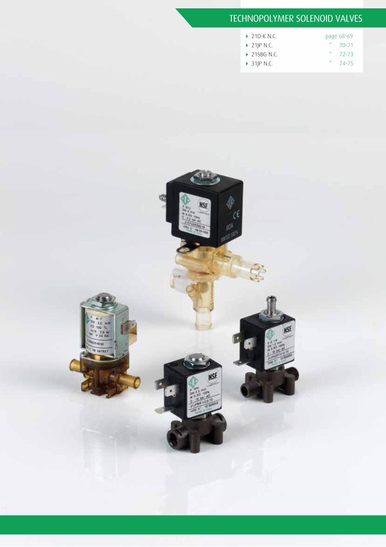
4 21D-K N.C.
4 21JP N.C.
4 21SBG N.C.
4 31JP N.C.
TECHNOPOLYMER SOLENOID VALVES
page 68-69
“ 70-71
“ 72-73
“ 74-75

68
21D-K N.C.
FEATURES
4 Totally separation valve4 Reliable solution for hot water application4 Flow regulation for hot water control4 90° shape for compact installation4 Directly connected to the boiler4 Reliable switch on-off time for accurate dispensing4 Modular system for multiple valve manifold4 NSF approved version
N.C.
PIPEØ
(mm)Kv
(l/min)MAX VISCOSITY
cSt (°E)PRESSURE
min GAS CODE CODE NTP DRAWINGREFERENCE
PRESSURE MAX MOPD (bar)
COIL TYPEAC
BB IIDC
9
9
9
9
9
9
9
9
9
9
9
9
9
9
9
9
9
9
9
9
Ø 12
Ø 12
Ø 12
Ø 12
Ø 11
Ø 11
Seeconnection
typesoverleaf
(A-B-D-I-L-R)
(Not available)
*
*
*
*
*
*
*
*
*
*
*
*
*
*
*
*
*
*
*
*
0,3
0,3 0,3
0,3 0,3
0,3 0,3
0,3 0,3
0,3
0,3 0,3
0,3 0,3
0,3 0,3
0,3 0,3
0,3
0,3 0,3
0,3 0,3
0,3
0,3 0,3
0,3 0,3
0,3 0,3
0,3
0,3
0,3
0,3
0,3
0,3
0,3
0,3
0,3
0,3
-
-
-
-
-
-
-
-
-
-
-
-
-
-
-
-
-
-
-
-
0
0
0
0
0
0
0
0
0
0
0
0
0
0
0
0
0
0
0
0
21D72KRS90-M
21D72KRS90-L
21D72KRS90-R
21D72RRS90-M
21K72KRS90-000
21K72RRS90-000
24K72KRS90-000
24K72RRS90-000
22K72KRS90-000
22K72RRS90-000
25K72KRS90-000
25K72KRS90-000
25K72RRS90-000
25K72RRS90-000
23K72KRS90-000
23K72RRS90-000
26K72KRS90-000
26K72RRS90-000
21D72RRS90-L
21D72RRS90-R
1
3
1
3
2
1
3
2
2
3
2
2
3
2
2
3
2
3
2
2
* FLOW RATE WITH HEAD OF 80mm=2,5 l/min.
21D27
Modelvalve
Orefice10-1mm
Ø= 12
See connection types overleaf(A-B-D-I-L-R)
KR= N.C.
RR= N.C.
S= VMQ 90
CONNECTION KR S 90
I= 28mm12 W
A= Class F 12= 12W
024= 24V
110= 110V
223= 220-230V
H= 50%
E= 50%
S= Without ApprovalC= 2 faston
I C A 12 024 E S
B= 30mmØ 13
A= Class F 08= 8W
024= 24V
110= 110V
223= 220-230V
C= DC
A= AC
S= Without ApprovalDEN 175301-803
B D A 08 024 A S

69
Total Separation Solenoid Salve 2/2 Way With Flow Regulation Direct Acting Dispenser Valve
TECHNICAL SPECIFICATION
4 Body material: PSU (Polysulphone)4 Armature tube: Brass - UNI EN 12164 CW614N4 Plungers: Stainless Steel AISI 400 series4 Spring: Stainless Steel AISI 300 series4 Media: water4 Ambient temperature: -10°C +60°C (-10°C +80°C with H coil class, depending on coils)4 Fluid temperature: +2°C +100°C with VMQ seals
AVAILABLE ON REQUEST
4 NSF approved version4 Monifold: (Please see key code for complete part numbering and for manifold construction)
1
1 2
2
Available NSFversion also
3
Section Section
INSTALLATION4 Maintenance and instruction sheet available in each solenoid valve box4 The valves can be connected directly on the boiler
REPAIR KITKR130KRS90-L3
REPAIR KITKR130KRS90-L3
Drawing Reference
Drawing Reference
Drawing Reference

70
21JP N.C.
FEATURES
4 Food grade4 High performance technopolymer4 Compact design
N.C.
NoteIn case glue is used to seal the fittings,verify the compatibility with body material (PPS)

71
Solenoid Valve 2/2 Way Direct Acting
TECHNICAL SPECIFICATION
4 Body material: PPS4 Armature tube (for JPARR - JP1RR) Brass UNI EN 12165 CW617N4 Armature tube (JPAR1 - JP1R1) Stainless Steel AISI 300 series4 Plungers: Stainless Steel AISI 400 series4 Spring: Stainless Steel AISI 300 series4 Media: air, water, inert gases, steam4 Ambient temperature: -10°C +60°C (-10°C+80°C with H coil class, depending on coils)4 Fluid temperature: -10°C +140°C with FKM seals4 Design pressure PS: 16 bar4 Protection class: IP65 (complete with electric plug)4 Electrical conformity: IEC3354 Switching time: 20 - 40 msec (depending on pressure conditions)
AVAILABLE ON REQUEST
4 NSF approved version
1
4 5
1 2
2
Available NSFversion also
Section Section
INSTALLATION4 The solenoid valves can be mounted in any position4 Holes and threaded connections for panel fixing4 Other port connections available on request4 Maintenance and instruction sheet available in each solenoid valve box
RELATED ITEMS4 P990307: Electrical plug EN 175301-803 Pg9
REPAIR KITCoil L 2,5W-5W(see coil list)
REPAIR KITCoil L 2,5W-5W(see coil list)
Drawing Reference Drawing Reference

72
21SBG N.C.
FEATURES
4 NSF approved version4 Totally separation Valve4 Fluid untouched when flowing
N.C.

73
Total Separation Solenoid Valve 2/2 Way Total Separation Direct Acting
TECHNICAL SPECIFICATION
4 Body material: PEI4 Armature tube: Brass - UNI EN 12164 CW614N4 Plungers: Stainless Steel AISI 400 serie4 Spring: Stainless Steel AISI 300 serie4 Media: water4 Up to 1 bar4 Ambient temperature: -10°C +60°C4 Fluid temperature: 0°C +95°C with EPDM seals4 Electrical conformity: IEC335
1
4 5
1
Section
RELATED ITEMS4 The solenoid valves can be mounted in any position4 Holes and threaded connections for panel fixing4 Other port connections available on request4 Maintenance and instruction sheet available in each solenoid valve box4 Availability of repair kit and coils as spares.
REPAIR KITCoil P/NRHLR7X024CS
Drawing Reference

74
31JP N.C.
FEATURES
4 Light and reliable4 Up to 15 bar4 Proven actuation system
NoteMax torque for fittings and nut assembly 2NmIn case glue is used to seal the fittings, verify the compatibility with body material (PPS)

75
Solenoid Valve 2/2 Way Direct Acting
TECHNICAL SPECIFICATION
4 Body material: PPS4 Armature tube (fig.1)Stainless Steel AISI 300 series4 Armature tube (fig.2) Brass - UNI EN 12165 CW617N4 Plungers: Stainless Steel AISI 400 serie4 Spring: Stainless Steel AISI 300 serie4 Media: air, water, inert gases, steam4 Ambient temperature: -10°C +60°C (-10°C +80°C with H coil class, depending on coils)4 Fluid temperature: -10°C + 140°C with FKM seals4 Design pressure PS: 16 bar4 Protection class: IP 65 (complete with electric plug)4 Electrical conformity: IEC3354 Switching time: 20-40 msec
AVAILABLE ON REQUEST
4 NSF approved version
1
4 5
1 2
2
Available NSFversion also
Section Section
INSTALLATION4 The solenoid valves can be mounted in any position4 Holes and threaded connections for panel fixing4 Other port connections available on request4 Maintenance and instruction sheet available in each solenoid valve box
RELATED ITEMS4 P990307: Electrical plug EN 175301-803 Pg9
REPAIR KITFor spare parts pleaseconsult our technicaldepartment
Coil P/NRLBARLBV
REPAIR KITFor spare parts pleaseconsult our technicaldepartment
Coil P/NRLBARLBV
Drawing Reference Drawing Reference


4 21Z N.C./N.O.
4 31Z N.C.
PINCH SOLENOID VALVES
page 78-79
“ 80-81

78
21Z N.C./N.O.
FEATURES
4 Totally separate Valve4 Up to 36 Kg closing force4 Fluid untouched when flowed

79
Pinch Solenoid Valve 2/2 Way Direct Acting - Bidirectional
TECHNICAL SPECIFICATION
4 Body material: Anodized Aluminium4 Armature tube: Brass - UNI EN 12164 CW614N4 Plungers: Stainless Steel AISI 400 series4 Spring: Stainless Steel AISI 300 series4 Pinching device POM C= Acetalic resin4 Ambient temperature: -10°C +40°C4 Protection class: IP65 (complete with electric plug)4 Electrical conformity: IEC3354 Switching time: 20-40 msec
AVAILABLE ON REQUEST
4 For different tube diameter or haedress, please consult our technical department
1
4 5
1 2
2
Section Section
INSTALLATION4 This S.V. is suitable for soft silicon tubings with hardness 55 ± 3 shore A.4 Tubing are not included in our supply.4 When used with less that 2,2mm external diameter pipes, a pipe holder should be mounted (for 21Z1).4 The solenoid valves can be mounted in any position4 Maintenance and instruction sheet available in each solenoid valve box
RELATED ITEMS4 P990305: Electrical plug EN 175301-803 Pg94 P990306: Electrical plug EN 175301-803 Pg114 P992126: Electrical plug EN 175301-803 Pg9 (with OR screw)4 P992127: Electrical plug EN 175301-803 Pg11 (with OR screw)4 P992128: Electrical plug EN 175301-803 cable 2 wires, 53cm4 R452714: Antihumidity kit (up to IP67 protection together with plugs P992126, P992127; P992128 & H coils class)4 P992087: Timer for automatic switch
REPAIR KITFor spare parts pleaseconsult our technicaldepartment
Coil P/NFor 21Z16: RMAA0424CSFor other : Coil B type (08W) Coil G type (14W) Coil U type (12W)
REPAIR KITFor spare parts pleaseconsult our technicaldepartment
Drawing Reference Drawing Reference

80
31Z N.C.
FEATURES
4 Totally separate valve4 Up to 36 Kg closing force4 Fluid untouched when flowed4 Bidirectional flow control4 Suitable for food pharmaceutical and medical application

81
Pinch Solenoid Valve 3/2 Way Direct Acting - Bidirectional
TECHNICAL SPECIFICATION
4 Body material: Anodized Aluminium4 Armature tube: Brass - UNI EN 12164 CW614N4 Plungers: Stainless Steel AISI 400 series4 Spring: Stainless Steel AISI 300 series4 Pinching device POM C= Acetalic resin4 Ambient temperature: -10°C +40°C4 Protection class: IP65 (complete with electric plug)4 Electrical conformity: IEC3354 Switching time: 20-40 msec
AVAILABLE ON REQUEST
4 For different tube diameter or haedress, please consult our technical department
1
4 5
1
Drawing Reference
Section
INSTALLATION4 This S.V. is suitable for soft silicon tubings with hardness 55 ± 3 shore A.4 Tubing are not included in our supply.4 When used with less that 2,2mm external diameter pipes, a pipe holder should be mounted (for 21Z1).4 The solenoid valves can be mounted in any position4 Maintenance and instruction sheet available in each solenoid valve box
RELATED ITEMS4 P990305: Electrical plug EN 175301-803 Pg94 P990306: Electrical plug EN 175301-803 Pg114 P992126: Electrical plug EN 175301-803 Pg9 (with OR screw)4 P992127: Electrical plug EN 175301-803 Pg11 (with OR screw)4 P992128: Electrical plug EN 175301-803 cable 2 wires, 53cm4 R452714: Antihumidity kit (up to IP67 protection together with plugs P992126, P992127; P992128 & H coils class)4 P992087: Timer for automatic switch
REPAIR KITFor spare parts pleaseconsult our technicaldepartment


4 21A Ex N.C./N.O.
4 21IH Ex N.C.
4 21L Ex N.C.
4 21W Ex N.C./N.O.
4 21X Ex N.C.
4 31A2 Ex N.C.
4 31L Ex N.C.
EXPLOSION PROOF SOLENOID VALVES ATEX
page 84-85
“ 86-87
“ 88-89
“ 90-91
“ 92-93
“ 94-95
“ 96-97
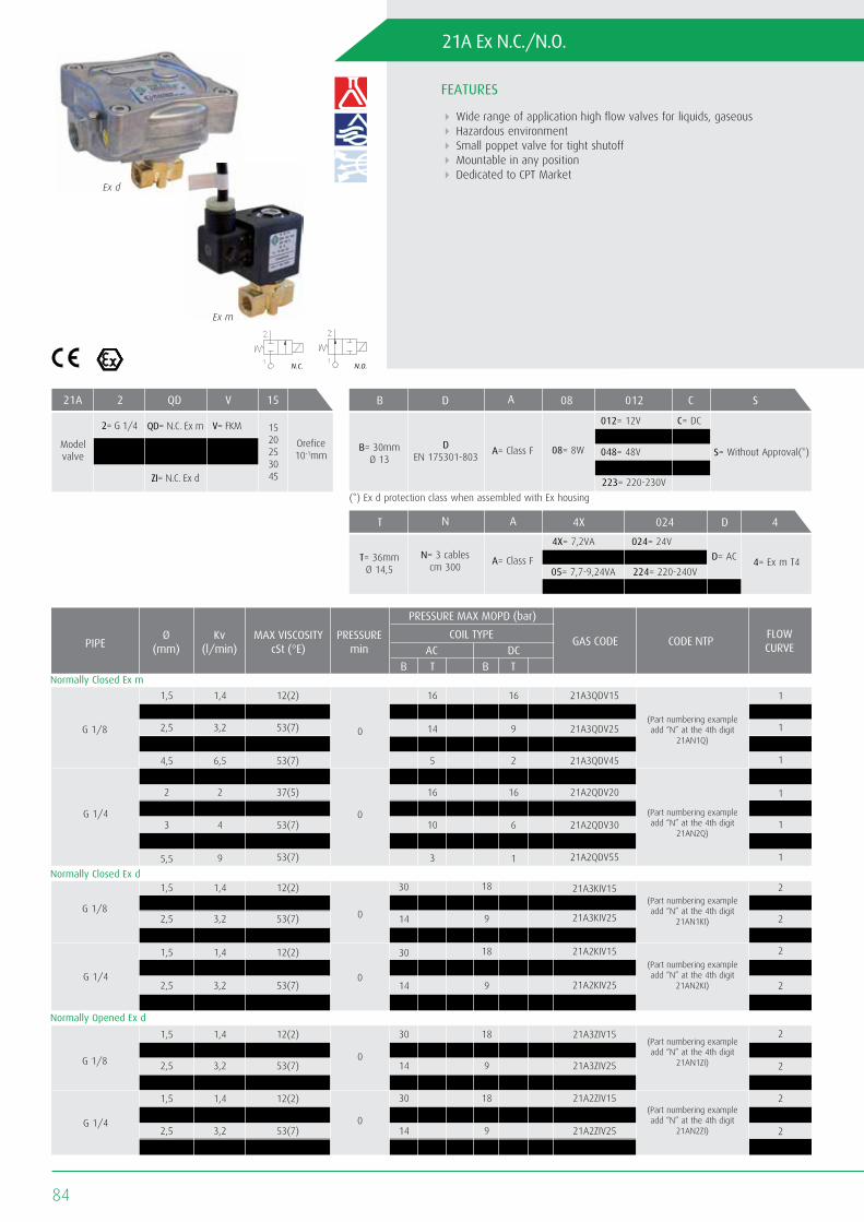
84
21A Ex N.C./N.O.
FEATURES
4 Wide range of application high flow valves for liquids, gaseous4 Hazardous environment4 Small poppet valve for tight shutoff4 Mountable in any position4 Dedicated to CPT Market
N.O.N.C.
Ex d
Ex m

85
Atex - Solenoid Valve 2/2 Way Direct Acting Explosion Proof
TECHNICAL SPECIFICATION
4 Body material: Brass UNI EN 12165 CW617N4 Armature tube: Stainless Steel AISI 300 series4 Plungers: Stainless Steel AISI 400 series4 Spring: Stainless Steel AISI 300 series4 Ex d Housing in Aluminium die cast4 Media: mineral oils, gasoline, diesel, fuel oils, air, inert gases, water, 134 a, R 404a4 Ex m Ambient temperature: -20°C +50°C4 Ex m Fluid temperature: -10°C +80°C with FKM seals -20°C + 80°C with H-NBR seals4 Ex d Ambient temperature: -20°C +60°C4 Ex d Fluid temperature: -10°C +140°C with FKM seals4 Design pressure PS: 40 bar4 Protection class: Ex m IP65 (complete with electric plug); Ex IP 67 (with cable gland)4 Electrical conformity: IEC335
4 Switching time: 20 - 40 msec (depending on pressure conditions)4 (Conforme to Atex Directive 94/9/CE ATEX) For S.V. 21A3..I II 2G Ex d II C T6 II 2D Ex tD A21 IP67 80°C For S.V. 21A..Q II 2G Ex mb II T 4 II 2D Ex tD A21 IP 65 T130°C
1
1 2
2
Drawing Reference Drawing Reference
Section Section
INSTALLATION4 The solenoid valves can be mounted in any position4 Maintenance and instruction sheet available in each solenoid valve box4 Attention: for fuse selection please refer to the “Instruction sheet Atex products” delivered together with the valve4 Fixing holes4 Holes and threaded connections for panel fixing
REPAIR KITFor spare parts pleaseconsult our technicaldepartment
Coil P/N Ex mb II T 4RTNA4X024D4RTNA5X110D4RTNA05224DARTNA10024C4
REPAIR KITFor spare parts pleaseconsult our technicaldepartment
ACCESSORIESCode P992219 Cable Gland(to be ordered separately)

86
21IH Ex N.C.
FEATURES
4 Wide range of application high flow valves for liquids, gaseous4 Hazardous environment4 Small poppet valve for tight shutoff4 Mountable in any position4 Dedicated to CPT Market
N.C.
Ex d

87
Atex - Solenoid Valve 2/2 Way - Combined operation Explosion Proof
TECHNICAL SPECIFICATION
4 Body material: Stainless Steel AISI 3164 Armature tube: Stainless Steel AISI 3164 Plungers: Stainless Steel AISI 400 Series4 Spring: Stainless Steel AISI 300 Series4 Ex d Housing in Aluminium die cast4 Media: air, inert gases, water, mineral oils, gasoline, diesel4 Ambient temperature: -20°C +60°C4 Fluid temperature: -10°C +80°C with NBR seals -10°C +140°C with FKM seals4 Design pressure PS: 16 bar4 Electrical conformity: IEC3354 (Conforme to Atex Directive 94/9/CE ATEX) II 2G Ex d II C T6 II 2D Ex tD A21 IP67 80°C
1
4
1
Drawing Reference
Section
INSTALLATION4 The solenoid valves can be mounted in any position4 Other port connections available on request4 Maintenance and instruction sheet available in each solenoid valve box4 Attention: for fuse selection please refer to the “Instruction sheet Atex products” delivered together with the valve4 Availability of repair kit and coils as spares.
REPAIR KITFor spare parts please consult our technical department
ACCESSORIESCode P992219 Cable Gland (to be ordered separately)
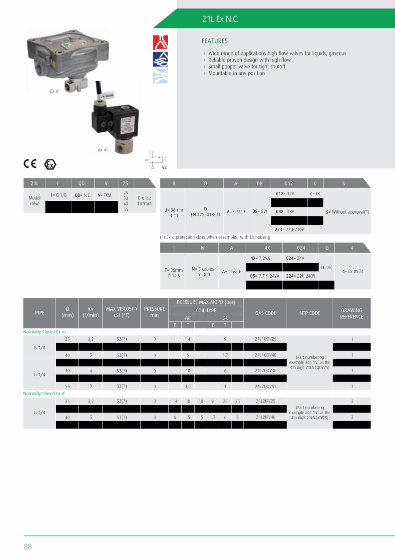
88
21L Ex N.C.
FEATURES
4 Wide range of applications high flow valves for liquids, gaseous4 Reliable proven design with high flow4 Small poppet valve for tight shutoff4 Mountable in any position
N.C.
Ex d
Ex m

89
Atex - Solenoid Valve 2/2 Way Direct Acting Explosion Proof
TECHNICAL SPECIFICATION
4 Body material: Stainless Steel AISI 3164 Armature tube: Stainless steel AISI 300 series4 Plungers: Stainless Steel AISI 400 series4 Spring: Stainless Steel AISI 300 series4 Ex d Housing in Aluminium die cast4 Media: mineral oils, gasoline, diesel, fuel oils, air, water, inert gases, 134 a, R 404a4 Ex m Ambient temperature: -20°C +50°C4 Ex m Fluid temperature: -10°C +80°C with FKM seals -20°C +80°C with H-NBR seals4 Ex d Ambient temperature: -40°C +60°C4 Ex d Fluid temperature: -10 +80°C with FKM seals4 Design pressure PS: 40 bar4 Protection class: Ex m IP65 (complete with electric plug); Ex d IP67 (with cable gland)4 Electrical conformity: IEC335
4 (Conforme to Atex Directive 94/9/CE ATEX) For S.V. 21L..I II 2G Ex d II C T6 II 2D Ex tD A21 IP67 80°C For S.V. 21L..Q II 2G Ex mb II T 4 II 2D Ex tD A21 IP 65 T130°C
1
1 2
2
Drawing Reference Drawing Reference
Section Section
INSTALLATION4 The solenoid valves can be mounted in any position4 Maintenance and instruction sheet available in each solenoid valve box4 Attention: for fuse selection please refer to the “Instruction sheet Atex products” delivered together with the valve4 Fixing holes4 Holes and threaded connections for panel fixing
REPAIR KITFor spare parts pleaseconsult our technicaldepartment
Coil P/N Ex mb II T 4RTNA4X024D4RTNA5X110D4RTNA05224DARTNA10024C4
REPAIR KITFor spare parts pleaseconsult our technicaldepartment
ACCESSORIESCode P992219 Cable Gland(to be ordered separately)

90
21W Ex N.C./N.O.
FEATURES
4 Wide range of applications high flow valves for liquids, gaseous4 Reliable proven design with high flows4 Small poppet valve for tight shutoff4 Mountable in any position
21WA3Q 21W3Z
Ex d
Ex m
(Pressure Equipment Directive 97/23/CE) for S.V. 21WN7÷21WN9 - 21W5÷21W7
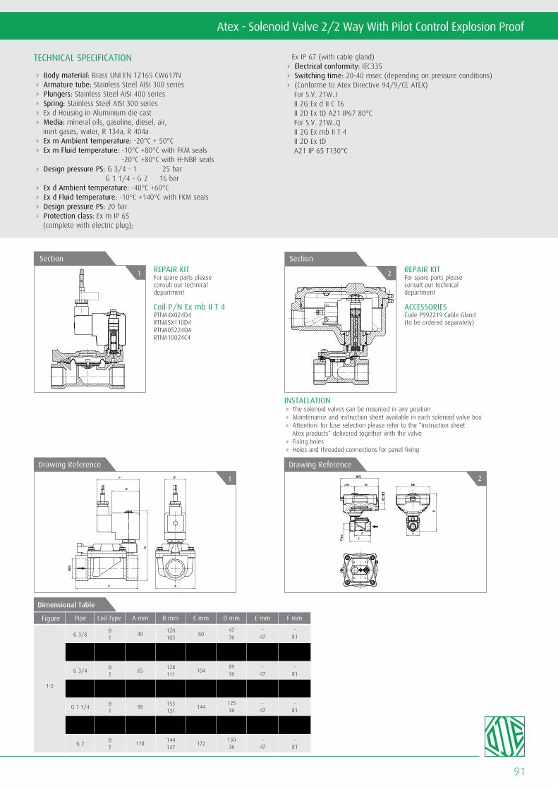
91
Atex - Solenoid Valve 2/2 Way With Pilot Control Explosion Proof
TECHNICAL SPECIFICATION
4 Body material: Brass UNI EN 12165 CW617N4 Armature tube: Stainless Steel AISI 300 series4 Plungers: Stainless Steel AISI 400 series4 Spring: Stainless Steel AISI 300 series4 Ex d Housing in Aluminium die cast4 Media: mineral oils, gasoline, diesel, air, inert gases, water, R 134a, R 404a4 Ex m Ambient temperature: -20°C + 50°C4 Ex m Fluid temperature: -10°C +80°C with FKM seals -20°C +80°C with H-NBR seals4 Design pressure PS: G 3/4 - 1 25 bar G 1 1/4 - G 2 16 bar4 Ex d Ambient temperature: -40°C +60°C4 Ex d Fluid temperature: -10°C +140°C with FKM seals4 Design pressure PS: 20 bar4 Protection class: Ex m IP 65 (complete with electric plug);
Ex IP 67 (with cable gland)4 Electrical conformity: IEC3354 Switching time: 20-40 msec (depending on pressure conditions)4 (Conforme to Atex Directive 94/9/CE ATEX) For S.V. 21W..I II 2G Ex d II C T6 II 2D Ex tD A21 IP67 80°C For S.V. 21W..Q II 2G Ex mb II T 4 II 2D Ex tD A21 IP 65 T130°C
1
1 2
2
Drawing Reference Drawing Reference
Section Section
INSTALLATION4 The solenoid valves can be mounted in any position4 Maintenance and instruction sheet available in each solenoid valve box4 Attention: for fuse selection please refer to the “Instruction sheet Atex products” delivered together with the valve4 Fixing holes4 Holes and threaded connections for panel fixing
REPAIR KITFor spare parts pleaseconsult our technicaldepartment
Coil P/N Ex mb II T 4RTNA4X024D4RTNA5X110D4RTNA05224DARTNA10024C4
REPAIR KITFor spare parts pleaseconsult our technicaldepartment
ACCESSORIESCode P992219 Cable Gland(to be ordered separately)
1-2
60
66
104
104
144
144
172
BT
BT
BT
BT
BT
BT
BT
G 3/8
G 1/2
G 3/4
G 1
G 1 1/4
G 1 1/2
G 2
40
40
65
65
98
98
118
4736
-47
-81
5036
-47
-81
8936
8936
12536
12536
15036
-47
-47
-47
-47
-47
-81
-81
-81
-81
-81
120103
120103
128111
136118
153131
153131
144147
Figure Pipe A mmCoil Type C mm D mm E mm F mmB mm
Dimensional Table

92
21X Ex N.C.
FEATURES
4 Dedicate to CPT Market4 Explosion proof rate4 Reliable construction
N.C.
Ex d
Ex m

93
Atex - Solenoid valve 2/2 way With pilot control Explosion proof
TECHNICAL SPECIFICATION
4 Body material: Stainless Steel AISI 3164 Armature tube: Stainless Steel AISI 300 series4 Plungers: Stainless Steel AISI 400 series4 Spring: Stainless Steel AISI 300 series4 Ex d Housing in Aluminium die cast4 Media: mineral oils, gasoline, diesel, fuel oils, air inert gases, water, 134 a, R 404a4 Ex m Ambient temperature: -20°C +50°C4 Ex m Fluid temperature: -10°C +80°C with FKM seals4 Ex d Ambient temperature: -20°C +60°C4 Ex d Fluid temperature: -10°C +80°C with H-NBR seals -10°C +140°C with FKM seals4 Design pressure PS: 25 bar4 Protection class: Ex m IP65 (complete with electric plug) Ex IP 67 (with cable gland)4 Electrical conformity: IEC3354 Switching time: 20-40 msec
(depending on pressure conditions)4 (Conforme to Atex Directive 94/9/CE ATEX) For S.V. 21X2Q.. II 2G Ex mb II T 4 II 2D Ex tD A21 IP 65 T130°C For S.V. 21X2KI.. II 2G Ex d II C T6 II 2D Ex tD A21 IP67 80°C
1
1 2
2
Drawing Reference Drawing Reference
Section Section
INSTALLATION4 The solenoid valves can be mounted in any position4 Maintenance and instruction sheet available in each solenoid valve box4 Attention: for fuse selection please refer to the “Instruction sheet Atex products” delivered together with the valve4 Holes and threaded connections for panel fixing
REPAIR KITFor spare parts pleaseconsult our technicaldepartment
Coil P/N Ex mb II T 4RTNA4X024D4RTNA5X110D4RTNA05224DARTNA10024C4
REPAIR KITFor spare parts pleaseconsult our technicaldepartment
ACCESSORIESCode P992219 Cable Gland(to be ordered separately)

94
31A2 EX N.C.
FEATURES
4 Wide range of applications high flow valves for liquids, gaseous4 Reliable proven design with high flows4 Small poppet valve for tight shutoff4 Mountable in any position
N.C.
Ex d
Ex m
A= Class F 08= 8W
110= 110V
012= 12V
024= 24V
048= 48V
223= 220-230V
C= DC
A= AC S= Without Approval(*)
DEN 175301-803
B D A 08 012 C S
B= 30mmØ 13
A= Class F
4X= 7,2VA
5X= 9,13VA
05= 7,7-9,24VA
10= 10,1W 024= 24V
024= 24V
110= 110V
224= 220-240V
C= DC
D= AC4= Ex m T4
N3 cables cm 300
T N A 4X 024 D 4
T= 36mmØ 14,5
31A
Modelvalve
Orefice10-1mm
2= G 1/4
3= G 3/8EI
N.C. Ex d
PD N.C. Ex m
V= FKM
F= H-NBR
15202530
3 PD V 15
(*) Ex d protection class when assembled with Ex housing
PIPEØ
(mm)Kv
(l/min)MAX VISCOSITY
cSt (°E)PRESSURE
minGAS CODE NTP CODE
FLOW CURVE
PRESSURE MAX MOPD (bar)
COIL TYPEAC
B BT TDC
G 1/8
G 1/8
G 1/4
G 1/4
0
0
1,5(*)
1(*)
2(*)
1,5(*)
2,5(*)
2(*)
3(*)
2,5(*)
1,5(*)
3(*)
2(*)
1(*)
2,5(*)
1,5(*)
3(*)
2(*)
2,5(*)
3(*)
1,2
0,45
2
1,2
3
2
3,5
3
1,2
3,5
2
0,45
3
1,2
3,5
2
3
3,5
12(2)
12(2)
37(5)
12(2)
53(7)
37(5)
53(7)
53(7)
12(2)
53(7)
37(5)
12(2)
53(7)
12(2)
53(7)
37(5)
53(7)
53(7)
31A3PDV15
31A3EIV10
(Part numbering example add “N” at the 4th digit
31AN1PD;31AN2PD)
(Part numbering example add “N” at the 4th digit
31AN1EI;31AN2EI)
31A3PDV20
31A3EIV15
31A3PDV25
31A3EIV20
31A3PDV30
31A3EIV25
31A2PDV15
31A3EIV30
31A2PDV20
31A2EIV10
31A2PDV25
31A2EIV15
31A2PDV30
31A2EIV20
31A2EIV25
31A2EIV30
0
0
10
15
15
20
6
10
5
6
10
20
15
5
6
15
5
10
6
5
10
15
15
20
6
10
5
6
10
20
15
5
6
15
5
10
6
5
1
2
1
2
1
2
1
2
1
2
1
2
1
2
2
1
2
2
Normally Closed Ex m
Normally Closed Ex d
(*) 3rd way exhaust= Ø 3 mm
(*) 3rd way exhaust= Ø 3 mm

95
Solenoid Valve 3/2 Way Direct Acting Explosion Proof
TECHNICAL SPECIFICATION
4 Body material: Brass UNI EN 12165 CW617N4 Armature tube: Stainles Steel AISI 300 series4 Plungers: Stainless Steel AISI 400 series4 Spring: Stainless Steel AISI 300 series4 Ex d Housing in Aluminium die cast4 Media: mineral oils, gasoline, diesel, fuel oils, air inert gases, water, 134 a, R 404a4 Ambient temperature: -20°C +50°C4 Ex m Fluid temperature: -10°C +80°C with FKM seals -20°C +80°C with H-NBR seals4 Ex d Ambient temperature: -20°C +60°C4 Ex d Fluid temperature: -10°C +140°C with FKM seals4 Design pressure PS: 40 bar4 Protection class: Ex m IP 65 (complete with electric plug); Ex IP 67 (with cable gland)4 Electrical conformity: IEC335
4 Switching time: 20-40 msec (depending on pressure conditions)4 (Conforme to Atex Directive 94/9/CE ATEX) For S.V. 31A3EI.. II 2G Ex d II C T6 II 2D Ex tD A21 IP67 80°C For S.V. 31A3P.. II 2G Ex mb II T 4 II 2D Ex tD A21 IP 65 T130°C
1
1 2
2
Drawing Reference Drawing Reference
Section Section
INSTALLATION4 The solenoid valves can be mounted in any position4 Maintenance and instruction sheet available in each solenoid valve box4 Attention: for fuse selection please refer to the “Instruction sheet Atex products” delivered together with the valve4 Holes and threaded connections for panel fixing
REPAIR KITFor spare parts pleaseconsult our technicaldepartment
Coil P/N Ex mb II T 4RTNA4X024D4RTNA5X110D4RTNA05224DARTNA10024C4
REPAIR KITFor spare parts pleaseconsult our technicaldepartment
ACCESSORIESCode P992219 Cable Gland(to be ordered separately)

96
31L EX N.C.
FEATURES
4 Ideal for piloting4 High flow rate4 Atex approval
N.C.
Ex d
Ex m
A= Class F 08= 8W
110= 110V
012= 12V
024= 24V
048= 48V
223= 220-230V
C= DC
D= AC
S= Without Approval(*)
DEN 175301-803
B D A 08 012 C S
B= 30mmØ 13
A= Class F
4X= 7,2VA
5X= 9,13VA
05= 7,7-9,24VA
10= 10,1W 024= 24V
024= 24V
110= 110V
224= 220-240V
C= DC
D= AC4= Ex m T4N
3 cables cm 300
T N A 4X 024 D 4
T= 36mmØ 14,5
31L
Modelvalve
Orefice10-1mm
1= G 1/8
2= G 1/4 EI N.C. Ex d
PD N.C. Ex m V= FKM
F= H-NBR
2030
1 PD V 20
(*) Ex d protection class when assembled with Ex housing
PIPEØ
(mm)Kv
(l/min)MAX VISCOSITY
cSt (°E)PRESSURE
min GAS CODE NTP CODE DRAWINGREFERENCE
PRESSURE MAX MOPD (bar)
COIL TYPEAC
B T TBDC
20(*)
20(*)
20(*)
20(*)
20(*)
20(*)
30(*)
30(*)
G 1/8
G 1/8
G 1/4
G 1/4
G 1/8
G 1/8
G 1/4
G 1/4
2
2
4
4
4
4
2
2
10
10
10
10
0
0
10
5
10
5
0
0
10
10
5
5
10
10
5
5
0
0
0
0
37(5)
37(5)
53(7)
53(7)
37(5)
37(5)
53(7)
53(7)
31LN1PDV20
31LN1EIV2031L1EIV20
31LN1PDV30
31LN1EIV3031L1EIV30
31L2PDV20
31L2EIV20
31L2PDV30
31L2EIV20
31LN2PDV20
31LN2EIV20
31LN2PDV30
31LN2EIV20
1
2
1
2
1
2
1
2
Normally Closed Ex m
Normally Closed Ex d
(Part numbering example remove“N” at the 4 th
digit 31L1PDV20)
(*) 3rd way exhaust= Ø 3 mm
(*) 3rd way exhaust= Ø 3 mm

97
Solenoid Valve 3/2 Way Direct Acting Explosion Proof
TECHNICAL SPECIFICATION
4 Body material: Stainless Steel AISI 3164 Armature tube: Stainless Steel AISI 300 series4 Plungers: Stainless Steel AISI 400 series4 Spring: Stainless Steel AISI 300 series4 Ex d Housing in Aluminium die cast4 Media: mineral oils, gasoline, diesel, fuel oils, air, water, inert gases, 134 a, R 404a4 Ambient temperature: -10°C +60°C (-10°C +80°C with class H coil, depending on coils)4 Ex m Ambient temperature: -20°C +50°C4 Ex m Fluid temperature: -10°C +80°C with FKM seals -20°C +80°C with H-NBR seals4 Ex d Ambient temperature: -40°C +60°C4 Ex d Fluid temperature: -10°C + 80°C with FKM seals4 Design pressure PS: 40 bar4 Protection class: Ex m IP 65 (complete with electric plug); Ex IP 67 (with cable gland)
4 Electrical conformity: IEC3354 (Conforme to Atex Directive 94/9/CE ATEX) For S.V. 31L..I II 2G Ex d II C T6 II 2D Ex tD A21 IP67 80°C For S.V. 31L..P II 2G Ex mb II T 4 II 2D Ex tD A21 IP 65 T130°C
1
1 2
2
Drawing Reference Drawing Reference
Section Section
INSTALLATION4 The solenoid valves can be mounted in any position4 Maintenance and instruction sheet available in each solenoid valve box4 Attention: for fuse selection please refer to the “Instruction sheet Atex products” delivered together with the valve4 Fixing holes4 Holes and threaded connections for panel fixing
REPAIR KITFor spare parts pleaseconsult our technicaldepartment
Coil P/N Ex mb II T 4RTNA4X024D4RTNA5X110D4RTNA05224DARTNA10024C4
REPAIR KITFor spare parts pleaseconsult our technicaldepartment
ACCESSORIESCode P992219 Cable Gland(to be ordered separately)


4 HIGH PRESSURE
HIGH PRESSURE SOLENOID VALVES
page 100-101

100
HIGH PRESSURE
N.O.N.C.
TECHNICAL SPECIFICATION
4 Body material: Brass UNI EN 12165 CW617N (for 21A1K0R30-TXC;21A2K0T12-XC;21AN2K0T12-XC; 21A1ZT11D-GB)4 Body material: Brass UNI EN 12164 CW614N (for 4739MZU190;4731K0T70;4966K0Q120;4592MZU190; 4966Z0Q120D)4 Armature tube: Stainless Steel AISI 300 series4 Plungers: Stainless Steel AISI 400 series4 Spring: Stainless Steel AISI 300 series4 Piston: POM C (for 4739MZU190;4592MZU190)4 Piston ring: Modified PTFE (for 4739MZU190;4592MZU190)4 Main seal: POM C=Acetalic resin (for 592MZU190;4739MZU190) T=PTFE (for 4731K0T70); Q=PBT (for 4966K0Q120;4966Z0Q120D)4 Pilot seal: TPU=Polyurethane resin (for 4739MZU190; 4592MZU190; 4966Z0Q120D); PTFE modified (for 4731K0T70; 4966K0Q120)4 Seal: RUBY (for 21A1K0R30-TXC); PTFE (for 21A1ZT11D-GB; 21A2K0T12-XC)4 Media: water, steam, mineral oils, gas oil, fuel oils (for 21A1K0R30-TXC); air, inert gases (for 4739MZU190);

101
Solenoid Valve 2/2 Way Direct Acting
4
1 2
2
3
1
air, water (for 21A2K0T12-XC; 4731K0T70; 4966Z0Q120D); air, water, steam, mineral oils (for 21A1ZT11D-GB)4 Ambient temperature: -40°C + 60°C (-40°C+80°C with H coil class, depending on coils) for 21A1K0R30-XC; -10°C + 80°C with H class for 4739MZU190; -10°C + 60°C (-10°C+80°C with H coil class, depending on coils) for 21A2K0T12-XC; 4731K0T70; 21AN2K0T12-XC; 4966K0Q1204 Fluid temperature: -40°C +180°C with RUBY, PTFE seals (for 21A1K0R30-TXC;21A2K0T12-XC;21AN2K0T12-XC) -10°C +100°C with POM C seals (for 4739MZU190; 4592MZU190) -40°C +98°C with PTFE seals (for 4731K0T70); -10°C + 90°C with PBT seals (for 4966K0Q120; 4966Z0Q120D)4 Design pressure PS: 40 bar (for 21A1K0R30-XC); PS: 50 bar (for 4739MZU190; 4592MZU190); PS: 100 bar (for 21A2K0T12-XC; 21AN2K0T12-XC; 4966K0Q120); PS: 150 bar (for 4731K0T70); PS: 80 bar (for 4966Z0Q120D)
4 Protection class: IP65 (complete with electric plug); IP67 (for 21AZT11D-GB);4 Electrical conformity: IEC3354 Switching time: 20-40 msec (depending on pressure conditions)
Drawing Reference Drawing Reference
Section Section
RELATED ITEMS4 P990305: Electrical plug EN 175301-803 Pg94 P990306: Electrical plug EN 175301-803 Pg114 P992126: Electrical plug EN 175301-803 Pg9 (with OR screw)4 P992127: Electrical plug EN 175301-803 Pg11 (with OR screw)4 P992128: Electrical plug EN 175301-803 cable 2 wires, 53cm4 R452714: Antihumidity kit (up to IP67 protection together with plugs P992126, P992127; P992128 & H coils class)4 P992087: Timer for automatic switch
ISTALLATION4 The solenoid valves can be mounted in any position4 Maintenance and instruction sheet available in each solenoid valve box4 Repair kit and coils available as spares
REPAIR KITNormally ClosedCoil B type (8W)KT130KR30-AP (for 21A1K0R30-XC)KT130KT30-AP (for 21A2K0T12-XC;21AN2K0T12-XC; 4731K0T70;for 4966K0Q120)
REPAIR KITNormally OpenedKT130ZT30-FGB (for 21A1ZT11D-GB)KT130ZT30-F (for 4966Z0Q120D)


4 21IA N.O.
4 21IA N.C.
4 21IH-5 N.C.
AIR OPERATED VALVES
page 104-105
“ 106-107
“ 108-109

104
21IA N.O.
FEATURES
4 Angle seat for high flow rate configuration4 Long life cycles4 N.C. and N.O. convertible after the delivery4 Flow below and above the the piston4 Service free solution4 Anti hummer effect
N.O.
(Pressure Equipment Directive 97/23/CE) for S.V. 21IA7 ÷ 21IA9

105
3
Valve 2/2 Way - Flow Direction Below Seat - Angle Seat Pilot Valve Pneumatically Actuated
TECHNICAL SPECIFICATION
4 VALVE FEATURES Fluid Temperature: -10°C +180°C Environment temperature: -10°C +60°C Material: Stainless Steel AISI 316 series PTFE, FKM packing gland4 PILOT ACTUATOR FEATURES Media: Dry Air or lubrificated, gas and neutral fluids Fluid Temperature: max +60°C Body: Polyamide 66 with 30% glass fibre NBR Gaskets Actuator Ø 70 Self adjusting Teflon seat
AVAILABLE ON REQUEST
4 Pilot Valve 31A2AV20+BDA (see 31A catalogue page)4 Position indicator4 Bistable version4 Water piloting system
1
1 2
2
Drawing Reference Drawing Reference Drawing Reference
Section Section
INSTALLATION4 The solenoid valves can be mounted in any position4 Maintenance and instruction sheet available in each solenoid valve box

106
21IA N.C.
FEATURES
4 Angle seat for high flow rate configuration4 Long life cycles4 N.C. and N.O. convertible after the delivery4 Flow below and above the piston4 Service free solution4 Anti hummer effect

107
Valve 2/2 Way - Flow Direction Below Seat - Angle Seat Pilot Valve Pneumatically Actuated
TECHNICAL SPECIFICATION
4 VALVE FEATURES Fluid Temperature: -10°C +180°C Environment temperature: -10°C +60°C Material: Stainless Steel AISI 316 series PTFE, FKM packing gland4 PILOT ACTUATOR FEATURES Media: Dry Air or lubrificated, gas and neutral fluids Fluid Temperature: max +60°C Body: Polyamide 66 with 30% glass fibre NBR Gaskets Actuator Ø 70 Self adjusting Teflon seat
AVAILABLE ON REQUEST
4 Pilot Valve 31A2AV20+BDA (see 31A catalogue page)4 Position indicator4 Bistable version4 Water piloting system
1 2
21
Drawing Reference Drawing Reference
Section Section
INSTALLATION4 The solenoid valves can be mounted in any position4 Maintenance and instruction sheet available in each solenoid valve box

108
21IH-5 N.C.
FEATURES
4 Angle seat for high flow rate configuration4 Long life cycles4 Flow below and above the the piston4 Service free solution4 Anti hummer effect

109
Valve 2/2 Way - Flow Direction Below Seat - Angle Seat Pilot Valve
TECHNICAL SPECIFICATION
4 VALVE FEATURES Fluid Temperature: -10°C +180°C Environment temperature: -10°C +60°C Material: Stainless Steel AISI 316 series PTFE, FKM packing gland4 PILOT ACTUATOR FEATURES Media: Dry Air or lubrificated, gas and neutral fluids Fluid Temperature: max +60°C Body: Polyamide 66 with 30% glass fibre NBR Gaskets Actuator Ø 50 Self adjusting Teflon seat
AVAILABLE ON REQUEST
4 Pilot Valve 31A2AV20+BDA (see 31A catalogue page)4 Position indicator4 Bistable version4 Water piloting system
4 5
1
1
Drawing Reference
Section
INSTALLATION4 The solenoid valves can be mounted in any position4 Maintenance and instruction sheet available in each solenoid valve box


4 P992087
4 P992219
4 P990305-P992257
ACCESSORIES
page 112
“ 113
“ 114-115

112
P992087 Condensate removal timer
FEATURES
The condensate removal timer is a plug-on controller specially design for drain valves. The unit offers an easy time cycle programming.The draining time can be set with the “ON” trimmer between 0.5 and 10 seconds. The “OFF” trimmer allows to adjust the delay time between two draining cycles from 0.5 to 45 minutes. The unit is ready to control the valve as soon as the power is switched on.The ON/OFF sequence will be repeated so long as the unit is fed.Two LEDS indicate the output status. A “TEST” button is provided to check the cycle settings and to restart the control sequence from the output status “ON”.
USE
4 Condensate drainage system4 Timed systems
TECHNICAL SPECIFICATION
4 Supply voltage: 24 to 240V AC/DC±10% 50/60Hz4 Output voltage: same as supply voltage4 Load current: max.1A4 Standby current: 8mA max4 Operating temp. range: -40°C to +60°C4 Connector: EN 175301-803 / ISO 44004 Environmental protection: IP65 (assembled with delivered gaskets)4 Housing dimensions: 69 x 43 x 21mm4 On time: 0.5 to 10 seconds4 Off time: 0.5 to 45 minutes4 Scale accuracy: ±10%4 Indicators: Green LED – On phase; Red LED – Off phase.
MATERIALS
4 Shell: ABS-PA 7654 Gasket: NBR (nitrile)4 Description: 1. Push-button TEST 2. Green Led not supplied: output power present (ON) 3. Red Led load supplied: output power absent (OFF) 4. Trimmer “ON”: regulation time “ON” 5. Trimmer “OFF”: pause time regulation “OFF”
AVAILABLE ON REQUEST
4 Connectors for EV (to be order separately)4 Pg 9 (6÷8mm) or Pg 11(8÷10mm)4 In the near future available also with UL approval.4 In accordance with RoHS.
Drawing Reference

113
P992219 Atex Cable gland Ex d
FEATURES
Cable glands for unarmoured cable, outer sealThe sealing ring seals and bloks cable on the outer sheathAmbient temperatureSeal E =EPDM - 40°C + 100°C S=VMQ - 70°C + 220°CProtection degree IP 66/68
For indoor and autdoor applicationsGroup II, category 2D, Zone 21, 22presence of combustible dust zoneGroup II, category 2D, Zone 1, 2presence of explosive gas atmospheres
(Conforme to Atex Directive 94/9/CE ATEX)I M2 / II 2 GD IIC
Drawing Reference

114
P990305 ÷ P990306
P990307
P990322÷ P990525
P990305 - P992257
CODE COMPATIBLE COILS: CODE COMPATIBLE COILS:
SPARE PARTS:Standard: Number of contacts:
Supply voltage: Operating current: Max current: Contact resistance: Max conductor section:Housing: Cable entry:Code P990305 Code P990307 Code P990306 Cable diameter: Protection class: Insulation class: Sealing:
CODE COMPATIBLE COILS:
SPARE PARTS:Standard: Number of contacts:
Max voltage: Housing:Max current: Contact resistance: Max conductor section:Protection class: Insulation class:
P990305 ÷ P990306BD.. - GD.. - UDP990307LB..
EN 175301-8032 +
AC max 250VDC max 300V10 A16 A≤4 mOhm1,5 mm2PA (Polyamide)
Pg 09Pg 09Pg 11Pg 09 (6÷8 mm)Pg 11 (8÷10 mm)IP 65 EN 60529VDE 0110-1/89NBR -40°C +90°C
990322 ÷ P990525BD.. - GD.. - HD.. - UD..
EN 175301-8032 +
max 250VPP (Polyamide)5A≤4 mOhm1 ,5 mm2P 65 EN 60529P 65 EN 60529

115
Connector for electronic connections
P992126 ÷ P992127
P992121
CODE COMPATIBLE COILS: SPARE PARTS:Standard: Number of contacts:
Supply voltage: Operating current: Max current: Contact resistance: Max conductor section:Housing: Cable entry:Code. P992126Code. P992127 Cable diameter: Protection class: Insulation class: Sealing:
CODE COMPATIBLE COILS: SPARE PARTS:Standard: Number of contacts:
Supply voltage: Operating current: Max current: Contact resistance: Max conductor section:Housing: Cable entry: Cable diameter: Protection class: Insulation class: Sealing:
CODE COMPATIBLE COILS: SPARE PARTS:Standard: Number of contacts:
Supply voltage: Operating current: Max current: Contact resistance: Max conductor section:Housing: Cable entry: Cable diameter: Protection class: Insulation class: Sealing:
992126 ÷ P992127BD.. - GD.. - UD
EN 175301-8032 +
AC max 250VDC max 300V10 A16 A≤4 mOhm1,5 mm2PA (Polyamide)
Pg 09Pg 11Pg 09 (6÷8 mm)Pg 11 (8÷10 mm)IP 65 EN 60529VDE 0110-1/89NBR -40°C +90°C
992121BD.. - GD..
EN 175301-8032 +
AC max 250VDC max 300V10 A16 A≤4 mOhm1,5 mm2PA (Polyamide)Pg 09 - Pg 11Pg 09 (6÷8 mm)IP 65 EN 60529VDE 0110-1/89NBR -40°C +90°C
(Conforme to Atex Directive 94/9/CE ATEX)I I 3GD
992257LB..
EN 175301-8032 +
AC max 250V10 A16 A≤4 mOhm1,5 mm2PA (Polyamide)Pg 09 - Pg 11Pg 09 (6÷8 mm)IP 65 EN 60529VDE 0110-1/89WMQ -40°C +90°C
(Conforme to Atex Directive 94/9/CE ATEX)I I 3GD
Ex d
Ex d


COILS
4 BDA-BDF-BDV-BSA-BVA
4 BDV08024C3 ÷ BDV08230A3
4 GDH-GDV
4 GDV14024C3 ÷ GDV14230A3
4 LBA-LBF-LBV
4 LBV05024A3 ÷ LBV05230A3
4 UDA-UDV
4 TNA4X024D4 ÷ TNA10024C4
page 118-119
“ 120
“ 121
“ 122
“ 123
“ 124
“ 125
“ 126-127

118
BDA-BDF-BDV-BSA-BVA
BDA Molding material: PA - Black polyamide - class F (155°C)BDF Molding material: PPS - Black polyphenylensulphide - class H (180°C)BDV Molding material: PET - Black polyethylene - class H (180°C) Winding: In class H Electrical connections: With connector EN 175301-803 paragraph 5.3.1 Protection degree IP 65 EN 60529 (DIN 40050)
NOMINAL VOLTAGES TOLERANCES: DC +10% -5%; AC +10% -15%
BSA With cm 100 cable Molding material: PA - Black Polyamide - class F (155°C)BVA With cm50 cable Winding: In class H Electrical connections: Cables
NOMINAL VOLTAGES TOLERANCES: DC +10% -5%; AC +10% -15%
Other voltages and power absorptions available on demand and for quantities.

119
COILS 30 mm x Ø 13 mm
Latching coilsBDA Molding material: PA- Black polyamide - class F (155°C) Winding: In class H Electrical connections: With connector EN 175301-803 paragraph 5.3.1 Protection degree IP 65 EN 60529 (DIN 40050)
NOMINAL VOLTAGES TOLERANCES: DC +10% -5%
TECHNICAL OPERATING DATA:- Impulse feed from 4,5 to 24 Volts for a period lasting from 20 to 100 ms (see fig.3a).NOTE: To ensure correct operation the fluid should be filtered to eliminate all traces ofimpurity subject to magnetic attraction, which would inevitably deposit on the cores ofthe solenoid valve, which are always magnetized, causing the formation of oxide as wellas contact problem.
21
3a3
-A
OPENB
- ACLOSE
B
+
+
Drawing Reference
Drawing Reference
Drawing Reference
Drawing Reference

120
ELECTROMAGNET 30 mm x Ø 13 mm for potentially explosive construction Ex nABDV08024C3 ÷ BDV08230A3
BDV Molding material: PET - Black polyethylene - class H (180°C) Winding: In class H Electrical connections: With connector EN 175301-803 paragraph 5.3.1 Protection degree IP65 EN 60529 (DIN 40050) Ambient temperature: 10°C +60°C
NOMINAL VOLTAGES TOLERANCES: DC +10% -5%; AC +10% -15%
(According to Directive 94/9/CE ATEX )II 3G Ex nA IIC T3II 3D Ex tD A22 IP65 T200°C
1
Ex nA
Drawing Reference
NoteThe coil to comply Atex protection category mentioned above will be supplied only with connector ATEX typeEx II 3GD IP65.ODE code has to be ordered separately: 992221Available on request and with minimum quantities.

121
GDH Molding material: EP - Black epoxy resin - class H (180°C)GDV Molding material: PET - Black Polyethylene - class H (180°C) Winding: In class H Electrical connections: With connector EN 175301-803 paragraph 5.3.1 Protection degree IP 65 EN 60529 (DIN 40050)
NOMINAL VOLTAGES TOLERANCES: DC + 10% - 5% ; AC + 10% - 15%
1
Drawing Reference
COILS 52 mm x Ø 13 mmGDH-GDV

122
ELECTROMAGNET 52 mm x Ø 13 mm for potentially explosive construction Ex nAGDV14024C3 ÷ GDV14230A3
GDV Molding material: PET - Black polyethylene - class H (180°C) Winding: In class H Electrical connections: With connector EN 175301-803 paragraph 5.3.1 Protection degree IP65 EN 60529 (DIN 40050) Ambient temperature: 10°C +60°C
NOMINAL VOLTAGES TOLERANCES: DC +10% -5%; AC +10% -15%
(According to Directive 94/9/CE ATEX )II 3G Ex nA IIC T3II 3D Ex tD A22 IP65 T200°C
Ex nA
1
Drawing Reference
NoteThe coil to comply Atex protection category mentioned above will be supplied only with connector ATEX type Ex II 3GD IP65.ODE code has to be ordered separately: 992221Available on request and with minimum quantities.

123
LBA Molding material: PA - Black polyamide - class F (155°C)LBF Molding material: PPS - Black poliphenylensulphide - class H (180°C)LBV Molding material: PET - Black Polyethylene - class H (180°C) Winding: In class H Electrical connections: With connector EN 175301-803 whellbase 11 Protection degree IP 65 EN 60529 (DIN 40050)
NOMINAL VOLTAGES TOL ERANCES: DC +10% -5%; AC +10% -15%
1
Drawing Reference
(1) Standard cycle time 1 minute, for different requirements please contact our Customer Service.Other voltages and power absorptions available on demand and for quantities.
COILS 22 mm x Ø 10 mmLBA-LBF-LBV

124
ELECTROMAGNET 22 mm x Ø 13 mm for potentially explosive construction Ex nALBV05024A3 ÷ LBV05230A3
LBV Molding material: PET - Black polyethylene - class H (180°C) Winding: In class H Electrical connections: With connector EN 175301-803 whellbase 11 Protection degree IP65 EN 60529 (DIN 40050) Ambient temperature: 10°C +60°C
NOMINAL VOLTAGES TOLERANCES: DC +10% -5%; AC +10% -15%
(According to Directive 94/9/CE ATEX )II 3G Ex nA IIC T3II 3D Ex tD A22 IP65 T200°C
Ex nA
1
Drawing Reference
NoteThe coil to comply Atex protection category mentioned above will be supplied only with connector ATEX type Ex II 3GD IP65.ODE code has to be ordered separately: 992257Available on request and with minimum quantities.

125
UDA Molding material: PA - Black polyamide - class F (155°C)UDV Molding material: PET - Black Polyethylene - class H (180°C) Winding: In class H Electrical connections: With connector EN 175301-803 paragraph 5.3.1 Protection degree IP 65 EN 60529 (DIN 40050)
NOMINAL VOLTAGES TOLERANCES: DC +10% -5%; AC +10% -15%
1
Drawing Reference
Other voltages and power absorptions available on demand and for quantities.
COILS 36 mm x Ø 13 mmUDA-UDV

126
TNA4X024D4 ÷ TNA10024C4
TNA Molding material: PPS - Black polyphenylensulphide - class H (180°C) Winding: In class H Electrical connections: With connector EN 175301-803 paragraph 5.3.1 Protection degree IP 65 EN 60529 (DIN 40050)
NOMINAL VOLTAGES TOLERANCES: DC +10% -5% ; AC +10% -15%
(According to Directive 94/9/CE ATEX )II 2G Ex mb T4II 2D Ex tDIEC Ex m II T4A21 IP65 T130°C
Ex nA
Other voltages and power absorptions available on demand and for quantities.

127
ELECTROMAGNET 36 mm x Ø 14,5 mm for potentially explosive construction Ex mb II T4
The coils must be protected with an external fuse that has characteristics as per table.
AMBIENT TEMPERATURE: -20°C +50°CFLUID MAX TEMPERATURE: +80°C
1 1b1a
Drawing Reference Drawing Reference Drawing Reference


VIBRATION PUMPS
4 PX50
4 TP400
4 TP500
4 TP600
4 TP760
page 130
“ 131
“ 132
“ 133
“ 134

130
PX50 Series Solenoid Pump Phoenix
Performance P50 Pressure vs Flow Rate
0
100
200
300
400
500
600
700
800
0 2 4 6 8 10 12 14 16 18
Pressure [bar]
Flow
Rat
e [c
c/m
in]
Lower LimitMeanUpper Limit
Note: Continuous dry-run would damage the unit permanently
Flow Curve
Drawing Reference
APPLICATION
4 Coffee Machines4 Floor Cleaning Machines4 Steam Ironing Stations
SPECIFICATION
4 Outlet 4 Pressure 4 Fluids 4 Max Ambient Temperature 4 Max Fluid Temperature 4 Dead Head Pressure 4 Free Flow Rate
4 Power Consumption (max.) 4 Operating Voltage 4 Working cycle 4 Not require External Type Diode4 Coil Insulation 4 Terminals 4 Endurance 4 Coil Encapsulation
MATERIALS
4 Plunger 4 Spring 4 No return valve 4 Seal 4 Plastic parts
CERTIFIED BY
4 CE4 NSF4 UL 7784 VDE (IEC 60335-1, 60335-2-41)
Proven sealing system for reliable and long life application
Ordering part number:P992124-AP (230V 50Hz)P992182-AP (120V 60Hz)
G 1/815 barTap Water/Distilled Water35°C35°CSee Performance ChartSee Performance Chart
53W100Vac 50Hz/60Hz (JET)20Vac 60Hz (UL)230Vac/50Hz (VDE)1.0 min ON, 1 min OFF
Class F (155°C)Class H (180°C)depending on voltage6.3mm x 0.8mm Faston type18.000 cycles (at 8-10 bar)(base on 1 min ON, 1 min OFF)750°C GWI
Stainless SteelStainless SteelSintetic RubberNBR or equivalentPA66 Based Plastics

131
TP400 Series Solenoid Pump Phoenix
Note: Continuous dry-run would damage the unit permanently
Flow Curve
Drawing Reference
APPLICATION
4 Coffee Machines4 Floor Cleaning Machines4 Steam Ironing Stations
SPECIFICATION
4 Outlet 4 Pressure 4 Fluids 4 Max Ambient Temperature 4 Max Fluid Temperature 4 Dead Head Pressure 4 Free Flow Rate
4 Power Consumption (max.) 4 Operating Voltage 4 Working cycle 4 Not require External Type Diode4 Coil Insulation 4 Terminals 4 Endurance 4 Coil Encapsulation
MATERIALS
4 Plunger 4 Spring 4 No return valve 4 Seal 4 Plastic parts
CERTIFIED BY
4 CE4 NSF4 UL 7784 VDE (IEC 60335-1, 60335-2-41)
Proven sealing system for reliable and long life application
Ordering part number:TP400-100A-AAA-AP Series 400 Dosing Pump 100V 50/60HzTP400-120A-AAA-AP Series 400 Dosing Pump 120V 60HzTP400-224A-AAA-AP Series 400 Dosing Pump 230V 50Hz
G 1/820 barDistilled Water35°C35°CSee Performance ChartSee Performance Chart
53W100Vac 50Hz/60Hz (JET)120Vac 60Hz (UL)220/240Vac/50Hz (VDE)240Vac/50Hz (VDE)2.0 min ON, 1 min OFF
Class F (155°C)Class H (180°C)depending on voltage6.3mm x 0.8mm Faston type18.000 cycles (at 8-12 bar)(base on 1 min ON, 1 min OFF)750°C/850°C GWI
Stainless SteelStainless SteelSintetic RubberNBR or equivalentPA66 Based Plastics

132
TP500 Series Solenoid Pump Phoenix
Performance P500 Pressure vs Flow Rate
0
100
200
300
400
500
600
700
800
0 2 4 6 8 10 12 14 16 18
Pressure [bar]
Flow
Rat
e [c
c/m
in]
Lower LimitMeanUpper Limit
Note: Continuous dry-run would damage the unit permanently
Flow Curve
Drawing Reference
APPLICATION
4 Coffee Machines4 Floor Cleaning Machines4 Steam Ironing Stations
SPECIFICATION
4 Outlet 4 Pressure 4 Fluids 4 Max Ambient Temperature 4 Max Fluid Temperature 4 Dead Head Pressure 4 Free Flow Rate
4 Power Consumption (max.) 4 Operating Voltage
4 Working cycle 4 Not require External Type Diode4 Coil Insulation
4 Terminals 4 Endurance 4 Coil Encapsulation
MATERIALS
4 Plunger 4 Spring 4 No return valve 4 Seal 4 Plastic parts
CERTIFIED BY
4 CE4 NSF4 UL 7784 VDE (IEC 60335-1, 60335-2-41)
Proven sealing system for reliable and long life application
Ordering part number:TP500-100A-AAA-AP Series 500 Dosing Pump 100V 50/60HzTP500-120A-AAA-AP Series 500 Dosing Pump 120V 60HzTP500-224A-AAA-AP Series 500 Dosing Pump 230V 50Hz
G 1/815 barWater35°C35°CSee Performance ChartSee Performance Chart
53W100Vac 50Hz/60Hz (JET)120Vac 60Hz (UL)220-240 Vac 50Hz (VDE)230Vac 50Hz (VDE)240Vac 50Hz (VDE)2.0 min ON, 1 min OFF
Class F (155°C)Class H (180°C)depending on voltage6.3mm x 0.8mm Faston type18.000 cycles (at 6-8 bar)(base on 1 min ON, 1 min OFF)750°C/850°C GWI
Stainless SteelStainless SteelSintetic RubberNBR or equivalentPA66 Based Plastics

133
TP600 Series Solenoid Pump Phoenix
Performance P600 Pressure vs Flow Rate
0
100
200
300
400
500
600
700
0 2 4 6 8 10 12
Pressure [bar]
Flow
Rat
e [c
c/m
in]
Lower LimitMeanUpper Limit
Note: Continuous dry-run would damage the unit permanently
Flow Curve
Drawing Reference
APPLICATION
4 Coffee Machines4 Floor Cleaning Machines4 Steam Ironing Stations
SPECIFICATION
4 Outlet 4 Pressure 4 Fluids 4 Max Ambient Temperature 4 Max Fluid Temperature 4 Dead Head Pressure 4 Free Flow Rate
4 Power Consumption (max.) 4 Operating Voltage 4 Working cycle 4 Not require External Type Diode4 Coil Insulation 4 Terminals 4 Endurance 4 Coil Encapsulation
MATERIALS
4 Plunger 4 Spring 4 No return valve 4 Seal 4 Plastic parts
CERTIFIED BY
4 CE4 NSF4 UL 7784 VDE (IEC 60335-1, 60335-2-41)
Proven sealing system for reliable and long life application
Ordering part number:TP400-100A-AAA-AP Series 600 Dosing Pump 100V 50/60HzTP400-120A-AAA-AP Series 600 Dosing Pump 120V 60HzTP400-224A-AAA-AP Series 600 Dosing Pump 230V 50Hz
G 1/89 barDistilled Water35°C35°CSee Performance ChartSee Performance Chart
53W100Vac 50Hz/60Hz (JET)120Vac 60Hz (UL)220-240 Vac 50Hz (VDE)230Vac 50Hz (VDE)240Vac 50Hz (VDE)2.0 min ON, 1 min OFF
Class F (155°C)Class H (180°C)depending on voltage6.3mm x 0.8mm Faston type18.000 cycles (at 6-8 bar)(base on 1 min ON, 1 min OFF)750°C/850°C GWI
Stainless SteelStainless SteelSintetic RubberNBR or equivalentPA66 Based Plastics

134
TP760 Series Solenoid Pump Phoenix
Performance P760 Pressure vs Flow Rate
0
200
400
600
800
1000
1200
1400
1600
0 1 2 3 4
Pressure [bar]
Flow
Rat
e [c
c/m
in]
Lower LimitMeanUpper Limit
APPLICATION
4 Coffee Machines4 Floor Cleaning Machines4 Steam Ironing Stations
SPECIFICATION
4 Outlet 4 Pressure 4 Fluids 4 Max Ambient Temperature 4 Max Fluid Temperature 4 Dead Head Pressure 4 Free Flow Rate
4 Power Consumption (max.) 4 Operating Voltage 4 Working cycle 4 Not require External Type Diode4 Coil Insulation 4 Terminals 4 Endurance 4 Coil Encapsulation
MATERIALS
4 Plunger 4 Spring 4 No returnvalve 4 Seal 4 Plastic parts
CERTIFIED BY
4 CE4 NSF4 UL 7784 VDE (IEC 60335-1, 60335-2-41)
Proven sealing system for reliable and long life application
Ordering part number:TP760-100A-AAA-AP Series 760 Dosing Pump 100V 50/60HzTP760-120A-AAA-AP Series 760 Dosing Pump 120V 60HzTP760-224A-AAA-AP Series 760 Dosing Pump 220-240V 50Hz
G 1/82,5 barWater35°C35°CSee Performance ChartSee Performance Chart
40W or 53W100Vac 50Hz/60Hz (JET)120Vac 60Hz (UL)220-240 Vac 50Hz (VDE)230Vac 50Hz (VDE)240Vac 50Hz (VDE)2.0 min ON, 1 min OFF (53W)ed 100% (40W)
Class F (155°C) VDEClass H (180°C)depending on voltage6.3mm x 0.8mm Faston type18.000 cycles (at 1,2 bar)(base on 1 min ON, 1 min OFF)750°C/850°C GWI
Stainless SteelStainless SteelSintetic RubberNBR or equivalentPA66 Based Plastics
Note: Continuous dry-run would damage the unit permanently
Flow Curve
Drawing Reference

135

31APB SERIES NSF certified for Coffee and Vending machines.
21JPA SERIESthe same concept of the JP version with two male attacks.

TECHNOPOLYMER RANGE
WHAT ARE NEW PRODUCTS FOR TECHNOPOLYMER RANGE?
ODE is working really hardto add this new products
to its Technopolymer valves range.
The valves that will be soon available are:
the APB series, the sub base version,
available in 2/2 and 3/2 way for coffee
machines, vending, automation and heating.
The new JM series, developed from
the JP experience, it’s engineered
to be assembled very easily even
with other valves size in one single block.
They are specific for coffee machines, vending,
automation and sterilization applications.
The new JPA series based on the same JP
concept, it’s the version with 2 male attacks.
ONE MORE EXCUSE TO CHOOSE ODE
23M SERIES certifiable NSF upon request for Coffee, Vending machines, sterilization and water treatment.

5467 cartridge valve for special applications with neutral and aggressive fluids.

STAINLESS STEEL RANGE
ODE is working really hardto add this new products
to its Stainless Steel range.
The new 5467 and ALB series are
the new solenoid valves in Stainless Steel
for the hot water and steam applications.
ONE MORE EXCUSE TO CHOOSE ODE
31ALB SERIESthe same concept of the 31A series with subplate mounting and body in Stainless Steel for Coffee and Vending applications.
WHAT ARE NEW PRODUCTS FOR STAINLESS STEEL RANGE?

PROGRAMMABLE DIGITAL TIMER
PECU DRIVER to electronically control
the proportional valve range
FLOWMETER FOR COFFEE MACHINES

ACCESSORIES RANGE
ODE is working really hardto add this new productsto its Accessories range.
ODE will be very pleased to launch
to the market the new timer,
the flowmeter and the new PECU driver
for the proportional valves range.
ONE MORE EXCUSE TO CHOOSE ODE
WHAT ARE NEW PRODUCTS FOR ACCESSORIES RANGE?

142
CERTIFICATIONS
ISO 9001Identifies a series of norms and guidelines developedby ISO to provide a system of process quality control, aimed at improvingefficiency and effectiveness and customer satisfaction.
UL CertificateThe Component Mark UL “Recognised” is used for components that arepart of a larger assembly or installation. The ODE solenoid valve range includescoils approved both UL and CSA for Canadian market.
NSF CertificateThe ODE range includes solenoid valve version NSF approved for alimentarfluid compatibility.
PED CertificatePED (Pressure Equipment Directive) is applied to the design, manufacturing and comformance of pressure equipment.
VDE CertificateThe Verband Deutscher Elektrotechniker is the Association for Electrical, Electronic and Information Technologies and their related sciences, technologies and applications.The ODE solenoid valve range includes coils VDE certificated.
REACH CertificateThe new REACH regulation is aimed at regulating companies that handle more than1 ton/year of chemical substances (raw material and end product, such as cosmetics,household products, etc...) in Europe. This regulation will have a significant impact on importers and manufacturers.
RoHS DirectiveRoHS (Restriction of Hazardous Substances Directive ) is the equivalent to the 2002/95/CE regulation, adopted by the European Community in February 2003.It is closely ties to the 2002/96/CE regulation regarding the disposal of electrical and electronic equipment (also called WEEE from Waste Electrical and Electronic Equipment). It regulates the storage, recycling and recovery of electrical equipment and is part of a law aimed at dealing with the disposal of obsolete electronic equipment.
ATEX CertificateODE solenoid valve range also includes some product lines and their protectivesystem with ATEX certification, intended for use in potentially explosive atmospheresas per Directive 94/9/EC.
CE0051 CertificateThe ODE gas range includes approved models as per gas directive EC 0051 that sets out the essential safety requirements for gas appliances and for safety, control and regulation devices.
WMT CertificateThe ODE Laboratory has been authorized for the application of procedureWitnessed Manufacturer’s Testing (WMT).
0051

www.ode.it
GENERAL CATALOGUE
SOLENOID VALVES
ODE S.r.l.Registered Office and Work Plant
23823 Colico (LC) Via Borgofrancone, 18, Zona IndustrialeCommercial and Administration Office
20090 Segrate (MI) Via Modigliani, 45tel. +39.02.715429 fax +39.02.715144
Com
pany
repo
rtin
g to
Man
agem
ent a
nd C
oord
inat
ion
of W
aver
ton
Inte
rnat
iona
l Lim
ited
- O
DE
rese
rves
the
right
to m
ake
any
chan
ges
with
out p
rior n
otic
e. E
d. 0
1/20
13 c
od. 3
0006
2 EN
G ©
OD
E s.
r.l. -
All
right
s re
serv
ed.