Check Valves Type ABS
10
Ball valves Housing Cast iron EN-GJL-250 Ball (G 1¼" - G 2½") Phenolic resin Ball (DN 80 - DN 150) NBR with hollow aluminium core Fasteners Stainless steel Seal NBR Flap valve - G 1¼" Housing PA Flap seal NBR Plug screw M12 PA Fasteners Stainless steel Flap valve - G 1½" & G2" Housing PP Flap seal NBR Plug screw PA Fasteners Stainless steel H (m) Q (m 3 /h) 5 2.0 3.0 4.0 5.0 1.0 0.2 0.1 0.3 0.4 0.5 10 DN 100 20 30 40 50 100 1000 500 G 1¼” G 1½” G 2” G 2½” DN 80 DN 150 Type tested and monitored H = Total Head Q = Discharge Volume Silent shut-off and effective sealing. * No flutter of the flap in the case of long pipelines (flap valve). * Self-cleaning effect due to the ball movement (ball valve). * No wearing parts. * Venting device (selected valves). * Vertical or horizontal installation. * Minimum head losses. * Full pipe cross-section. * Maximum operating temperature 60 °C. * Materials Head losses Features Non-return valves of cast iron or plastic for horizontal or vertical discharge lines in accordance with EN 12050-4. Sulzer ball check valves Sulzer ball check valves are designed for use in drainage and sewer mains. The unique design of a ball check valve allows free movement of the ball and at the same time a good seal. In operation, the ball moves so that the entire pipe cross-section is free. Ball check valves are self-cleaning. Deposits on the ball which may form while it is in the closed position are removed by the rolling movement of the ball as it moves from the closed to the open position. The ball recess chamber has a removable cover which allows for internal inspection without the need to remove the valve from the discharge line. When fitting to horizontal discharge lines the ball recess chamber must be positioned above the horizontal axis of the valve. Sizes: G 1¼”, G 1½”, G 2”, G 2½” (with internal thread). DN 80, DN 100, DN 150 (with drilled flange connection). Rated pressure: 10 bar Sulzer flap check valves The Sulzer flap check valve is a synthetic non-return valve for use in drainage and wastewater mains. Its two-piece design features a single disc seal that operates on a moulded rubber hinge, and when open makes the total diameter of the pipe available for the passage of the medium. This results in a minimal pressure drop and avoids deposits or blockage. Venting of the pipe can be achieved by removing the plug screw. Sizes: G 1¼”, G 1½”/ G 2” (with internal thread). G 1½”/ G 2” converts between sizes by fitting/removal of threaded inserts (tool and inserts included). Rated pressure: 4 bar Water test pressure: 6 bar Check Valves Type ABS
-
Upload
khangminh22 -
Category
Documents
-
view
2 -
download
0
Transcript of Check Valves Type ABS

Ball valves
Housing Cast iron EN-GJL-250
Ball (G 1¼" - G 2½") Phenolic resin
Ball (DN 80 - DN 150) NBR with hollowaluminium core
Fasteners Stainless steel
Seal NBR
Flap valve - G 1¼"
Housing PA
Flap seal NBR
Plug screw M12 PA
Fasteners Stainless steel
Flap valve - G 1½" & G2"
Housing PP
Flap seal NBR
Plug screw PA
Fasteners Stainless steel
H (m)
Q (m3/h) 5
2.0
3.0
4.05.0
1.0
0.2
0.1
0.30.40.5
10
DN 1
00
20 30 40 50 100 1000500
G 1¼
”
G 1½
”G
2”
G 2½
”
DN 8
0
DN 1
50
Type testedand monitored
H = Total Head Q = Discharge Volume
Silent shut-off and effective sealing.*No flutter of the flap in the case of long pipelines (flap valve).*Self-cleaning effect due to the ball movement (ball valve).*No wearing parts.*Venting device (selected valves).*Vertical or horizontal installation.*Minimum head losses.*Full pipe cross-section.*Maximum operating temperature 60 °C.*
MaterialsHead losses
Features
Non-return valves of cast iron or plastic for horizontal orvertical discharge lines in accordance with EN 12050-4.
Sulzer ball check valvesSulzer ball check valves are designed for use in drainage andsewer mains. The unique design of a ball check valve allows freemovement of the ball and at the same time a good seal. Inoperation, the ball moves so that the entire pipe cross-section isfree.Ball check valves are self-cleaning. Deposits on the ball whichmay form while it is in the closed position are removed by therolling movement of the ball as it moves from the closed to theopenposition.The ball recess chamber has a removable cover which allows forinternal inspection without the need to remove the valve from thedischarge line.When fitting to horizontal discharge lines the ball recess chambermust be positioned above the horizontal axis of the valve.
Sizes: G 1¼”, G 1½”, G 2”, G 2½” (with internal thread). DN 80, DN 100, DN 150 (with drilled flange connection).
Rated pressure: 10 bar
Sulzer flap check valvesThe Sulzer flap check valve is a synthetic non-return valve for usein drainage and wastewater mains. Its two-piece design features asingle disc seal that operates on a moulded rubber hinge, andwhen open makes the total diameter of the pipe available for thepassage of the medium. This results in a minimal pressure dropand avoids deposits or blockage. Venting of the pipe can beachieved by removing the plug screw.
Sizes: G 1¼”, G 1½”/ G 2” (with internal thread).G 1½”/ G 2” converts between sizes by fitting/removal of threadedinserts (tool and inserts included).
Rated pressure: 4 barWater test pressure: 6 bar
Check Valves Type ABS

B
Type SizeA B C D E
Ball valvethreaded
G 1¼”G 1½”G 2"G 2½”
141150175214
128136159190
67 72 85100
50 53 62 75
- - - -
2.22.83.96.5
Ball valveflange(drilled)
DN 80DN 100DN 150
260300400
248286381
146194240
112130172
180240295
15.025.046.0
Flap valvethreaded G 1¼” 90 86 - - - 0.2
Flap valvethreaded
G 1½” / G 2" 150 125 - - - 0.7
Dimensions (mm) Weight (kg)
Sulzer ball check valves
Sulzer flap check valves
Che
ck V
alve
s Ty
pe A
BS
2014
-07-
02 |
We
rese
rve
the
righ
ts to
alt
er s
peci
ficat
ions
due
to te
chni
cal d
evel
opm
ents
.
AB
C
D
E
F
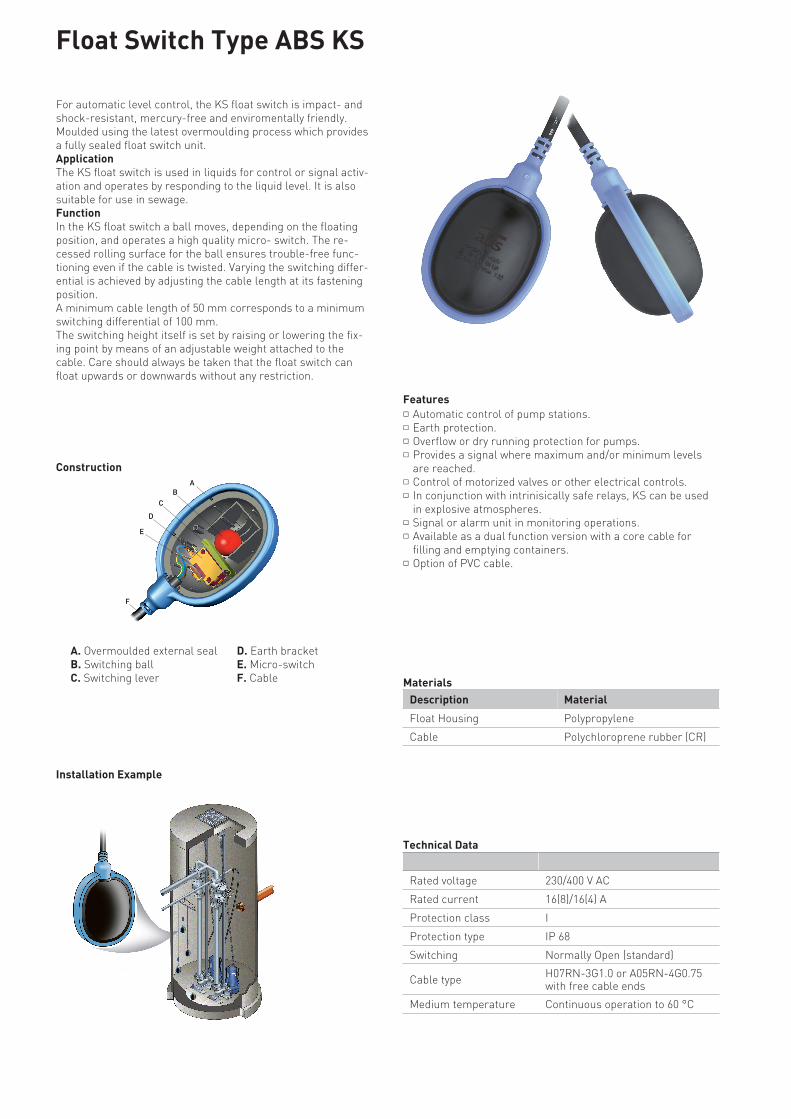
For automatic level control, the KS float switch is impact- andshock-resistant, mercury-free and enviromentally friendly.Moulded using the latest overmoulding process which providesa fully sealed float switch unit.ApplicationThe KS float switch is used in liquids for control or signal activ-ation and operates by responding to the liquid level. It is alsosuitable for use in sewage.FunctionIn the KS float switch a ball moves, depending on the floatingposition, and operates a high quality micro- switch. The re-cessed rolling surface for the ball ensures trouble-free func-tioning even if the cable is twisted. Varying the switching differ-ential is achieved by adjusting the cable length at its fasteningposition.A minimum cable length of 50 mm corresponds to a minimumswitching differential of 100 mm. The switching height itself is set by raising or lowering the fix-ing point by means of an adjustable weight attached to thecable. Care should always be taken that the float switch canfloat upwards or downwards without any restriction.
Installation Example
A. Overmoulded external sealB. Switching ballC. Switching lever Materials
D. Earth bracketE. Micro-switchF. Cable
FeaturesAutomatic control of pump stations.*Earth protection.*Overflow or dry running protection for pumps.*Provides a signal where maximum and/or minimum levelsare reached.
*
Control of motorized valves or other electrical controls.*In conjunction with intrinisically safe relays, KS can be usedin explosive atmospheres.
*
Signal or alarm unit in monitoring operations.*Available as a dual function version with a core cable forfilling and emptying containers.
*
Option of PVC cable.*
Rated voltage 230/400 V AC
Rated current 16(8)/16(4) A
Protection class I
Protection type IP 68
Switching Normally Open (standard)
Cable type H07RN-3G1.0 or A05RN-4G0.75with free cable ends
Medium temperature Continuous operation to 60 °C
Float Switch Type ABS KS
Description Material
Float Housing Polypropylene
Cable Polychloroprene rubber (CR)
Technical Data
Construction

A
B
C
3.
a
b
c
d
Accessories
*For level control of two and more pumps we have available — similar to the application for two pumps with 10 meters cable — a combination of ABS levelcontrol switches to the desired lengths.
a. Bracketb. Clampc. Cabled. Weight
A = AlarmB = OnC = Off
Options
1.KS Float Switch (standard)Normally Openwith free cable ends
0.55 m1 m5 m
10 m20 m30 m50 m
12800018128002821280002212800023128000251280002712800154
KS Float Switch (dual switching)for filling and emptying; 4-corerubber cable with free cable ends
10 m20 m50 m
128002871280028912800343
KS Float Switchwith fastening
KS-5 = 5 mKS-10 = 10 m
6245001662450017
2.KS Float Switch (with plug)for transportable ABS controlunits with KS connecting socket
KS-J 10 = 10 mKS-J 20 = 20 m
6245001862450020
ON/OFF; for onepump with twofloats
10 m20 m30 m
624500526245005462450056
ON/OFF; for onepump and alarmwith three floats
10 m20 m30 m
624500586245006062450062
ON/OFF; for twopumps* withfour floats
10 m20 m30 m
624550006245500362455004
3. Level Control KitKS float switch with wall mounting bracket and adjustable weights
Description Part no.
Wall Bracketsuitable for 2, 3 or 4 floats
31420572
Clampfor attaching float to wall bracket
41420570
Adjustable Weightfor setting switching level
62520011
Float Switch Hangerwhere wall bracket is not suitable and a hook is used
41425091
Description Size Part no.
Float switch hanger
141
86
1.
2.
Flo
at S
witc
h Ty
pe A
BS
KS
2014
-06-
26 |
We
rese
rve
the
righ
ts to
alt
er s
peci
ficat
ions
due
to te
chni
cal d
evel
opm
ents
.

ABS leakage relay CA 461
CA 461 is designed to spy and detect leakage in a pumps and mix-ers.
The amplifier is housed in a norm enclosure fitted for DIN-railmounting.
The unit is available in two executions, 24 VDC or 110-230 VACsupply.
To minimize the risk of false alarms the failure has to be detectedfor time duration of approximately 10 seconds.
To simplify the mounting the unit is fitted with plug-in type of con-nectors.
FeaturesLeakage monitoring with 10 sec alarm delay*Wide resistance range, 0-100 kOhm*Relay output 250 VAC 3 Ampere*Connection via plug in connectors*DIN-rail mounted*
Technical specifications
Leakage detection treshold < 100k ohm
Alarm on delay 10 seconds
Ambient operating temperature -20 to +70 ºC (-4 to +158 ºF)
Ambient storage temperature -30 to +80 ºC (-22 to +176 ºF)
Degree of protection IP 20, NEMA: Type 1
Housing material PPO and PC
Mounting DIN Rail 35 mm
Installation category CAT II
Pollution degree 2
Flame rate V0 (E45329)
Humidity 0-95% RH non-condensing
Dimensions 108 x 58 x 35 mm (4.25 x 2.28 x 1.38 in.)
Power supply 16907003: 110-230 VAC (Europe only) / 16907010: 110-230 VAC, CSA-approved
16907004: 18-36 VDC, SELV or Class 2 (Europe only) / 16907011: 18-36 VDC, CSA-approved
Fuse Max 10 A
Terminal wire size Use copper (Cu) wire only. 0.2 - 2.5 mm2 flexible core, stripped length 8 mm.
Terminal tightening torque 0.56 - 0.79 Nm (5-7 lbs-in)
Power consumption < 2 W
Max load output relay 250 VAC 3 Ampere
Altitude Max 2000 MASL or 6562 ft. AMSL
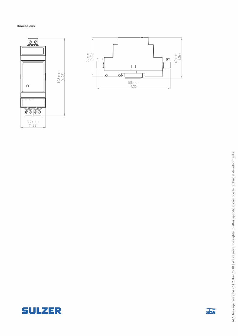
Dimensions
AB
S le
akag
e re
lay
CA
461
2014
-02-
18 |
We
rese
rve
the
righ
ts to
alt
er s
peci
ficat
ions
due
to te
chni
cal d
evel
opm
ents
.

ABS hydrostatic level sensor MD 126
Features:* Dry ceramic sensor* Accuracy ≤ 0.3 %* Cable according Bg V V-1.12.96 specifications
Technical specifications
Description
Material
Cable PE
Housing Stainless steel 1.4404
Sensor Ceramic AL203, gold coated
Output signal 4...20 mA, 2-wire, fixed to the
sensors measuring range
Accuracy ≤ ± 0.3 % FS @ 25 °C
Max overload 8 bar
Response time 200 ms
Supply voltage 9...30 V DC
Ambient temperature -25...80 °C
Temperature coeff. ≤ ± 0.015 % FS/K (Zero)
Long tem stability ≤ ± 0.3 % FS p.a.
Protection IP 68
Weight of sensor approx. 0.3 kg
Weight of cable 0.4 kg / 10 m
Electrical connection PE cable with pressure
compensation capillary and
filter
Dimensions (mm)
Ø 15.0Ø 28.0
Ø 7.4
92.0
Mounting level sensor MD 126In pits or tanks without turbulence the sensor can be mounted hanging freely in its cable.
If there is a strong turbulence we recommend that the sensor is protected inside a pipe, with a diameter of at least 50 mm, which is mounted vertical alongside the tank or pit wall.
Measuring Max. Cable Length
Range Overpressure
0 - 2.5 mH2O 4 bar 10 m
0 - 2.5 mH2O 4 bar 30 m
0 - 5 mH2O 8 bar 10 m
0 - 10 mH2O 8 bar 15 m

CEMD 126 conform with the following Council Directives and Generic standards:
Safety: EN61010-1:2001EMC: EN61326-1:2006
Electrical connections
U = 9…30V DC
+ + -
4…20 mA redblack
4...20 mA 2-wire
For cable lengths > 30 m shielded cable is used
Load diagram
40
30
2420
9
0
200
400
600
750
800
1000
1200
Max
load
in o
hm
Supply-voltage VDC
201
3-01
-07
| We
rese
rve
the
righ
ts to
alt
er s
peci
ficat
ions
due
to te
chni
cal d
evel
opm
ents
.

ABS temperature and leakage relay CA 462
CA 462 is designed to spy and detect leakage and temperature inpumps and mixers.The amplifier is housed in a norm enclosure fitted for DIN-railmounting.The unit is available in two executions, 24 VDC or 110-230 VACsupply.To minimize the risk of false alarms the leakage failure has to bedetected for time duration of approximately 10 seconds.To simplify the mounting the unit is fitted with plug-in type of con-nectors.The unit has separate alarm outputs for temperature and leakage.CA 462 also has main contactor relay output energized dependingon alarm/s with manual reset option.Included in the kit is also a Xylem MiniCas adaptor.
FeaturesLeakage monitoring with 10 sec alarm delay*Temperature monitoring*Relay output 250 VAC 3 Ampere*Connection via plug in connectors*DIN-rail mounted*
Technical specifications
Leakage detection threshold (+/-10%) < 100 kohm
Temp. input threshold (+/-10%) > 3.3 kohm (PTC / Klixon)
Leakage alarm delay 10 seconds
Ambient operating temperature -20 to +70 ºC (-4 to +158 ºF)
Ambient storage temperature -30 to +80 ºC (-22 to +176 ºF)
Degree of protection IP 20, NEMA: Type 1
Housing material PPO and PC
Mounting DIN Rail 35 mm
Installation category CAT II
Pollution degree 2
Flame rate V0 (E45329)
Humidity 0-95% RH non-condensing
Dimensions H x W x D: 108 x 70 x 58 mm (4.25 x 2.76 x 2.28 in.)
Power supply 16907006: 110-230 VAC / 16907007: 18-36 VDC SELV or Class 2
Fuse Max 10 A
Terminal wire size Use copper (Cu) wire only. 0.2 - 2.5 mm2 flexible core, stripped length 8 mm.
Terminal tightening torque 0.56 - 0.79 Nm (5-7 lbs-in)
Power consumption < 5 W
Max load alarm relays 250 VAC 3 Ampere resistive load
Altitude Max 2000 MASL or 6562 ft. AMSL
Max load output Pump blocking relay 250 VAC 6 Ampere resistive load

Dimensions
Alarm and relay function table:
Leakage Led Temp. Led Pump Relay Temp. Relay Leakage Relay
Alarm Closed Open Closed
Alarm Alarm Open Closed Closed
Closed Open Open
Alarm Open Closed Open
AB
S le
akag
e re
lay
CA
462
2014
-02-
03 |
We
rese
rve
the
righ
ts to
alt
er s
peci
ficat
ions
due
to te
chni
cal d
evel
opm
ents
.