Balancing Valves Handbook - PARTcommunity
36
Balancing Valves Handbook
-
Upload
khangminh22 -
Category
Documents
-
view
1 -
download
0
Transcript of Balancing Valves Handbook - PARTcommunity

BalancingValvesHandbook


3 Cimberio HandbookCimberio made in Italy
1 INTRODUCTION 4 2 THEIMPORTANCEOFFLOWREGULATION 4 2.1 Principlesforbalancinghydronicsystems 4 2.1.1 Heattransferatreducedflowrate 4 2.1.2 Heattransferatexcessiveflow 6 2.1.3 Chilledwaterterminal 6 3 REGULATINGVALVESANDFLOWMEASUREMENTDEVICES 7 3.1 Manualbalancingvalves 8 3.1.1 Examples:Comparisonbetweenabalanced andanunbalancedsystem 9 3.1.2 Doubleregulatingvalves 13 3.1.3 Regulating2-waycontrolvalve 13 3.1.4 Fixedorificeflowmeasurementdevices 14 3.1.5 Fixedorificedoubleregulatingvalves 15 3.1.6 Variableorificedoubleregulatingvalves 16 3.2 Fixedorificeversusvariableorifice 17 3.2.1 Flowmeasurementaccuracy 17 3.2.2 Whyflowmeasurementaccuracyisimportant 17 3.2.3 Conclusion 18 3.3 Automaticbalancingvalves 18 3.3.1 Constantflowregulator 18 3.3.2 Differentialpressurecontrolvalves 20 3.3.3 Pressureindependentcontrolvalves 23 4 DESIGNCONSIDERATIONS 25 4.1 Self-balancingarrangements 25 4.2 Velocities 26 4.3 Pumpselection 26 4.4 Variablespeedpumps 26 4.5 Systemcleanliness 26 4.6 Ventinganddraining 26 4.7 Access 27 5 GUIDELINESFORVALVESELECTION 27 5.1 Terminology 27 5.2 Selectioncriteria 28 5.3 Selectionprocedure 28 5.4 Softwareforselection 29 6 MEASURINGFLOWRATE 30 6.1 Fluorocarbon/mercurymanometer 30 6.2 Digitalmanometer 31 7 FLOWREGULATIONPROCEDURE 32 7.1 Proportionalbalancing 32 7.2 Indexcircuit 32 7.3 Proportionalbalancingprocedure 33 7.4 Reporting 33 8 INDEXOFFIGURES 34 9 INDEXOFTABLES 3510 BIBLIOGRAPHY 35
Index
BalancingValvesHandbook

4Cimberio made in Italy Cimberio Handbook
1.Introduction
Thisguideexplainshowtoselect,installandoperateCim-berio’srangeofregulatingvalvesandflowmeasurementdevices.Theproductsdiscussedareprimarilyintendedforuseinheatingandairconditioningsystems.
Theguideisintendedforengineersinvolvedinthedesignofsystems,andtheselectionofregulatingvalvesandflowmeasurementdevices.Itisalsoaimedatinstallingcontrac-torswhomayneedtointerprettheengineer’sinstructionsandinstalloroperatetheseproducts.
TheguidealsoestablishesthecaseforCimberio’shighaccuracyfixedorificeregulatingvalves.
This typeofvalvehasgeneralacceptance inmanypartsof the world due to the benefits of flow measurementaccuracyandperformance.ThereasonsforitsincreasingpopularityovervariableorificevalvesaresummarisedinSection3.2.
The advantages of automatic balancing valves are ana-lysedinSection3.3.
2.Theimportanceofflowregulation
Thepossibleconsequencesofinaccurateflowregulationareasfollows:
Failure to achieve design temperatures: Terminals re-ceiving too little flow may not deliver their intendedamountsofheatingorcooling.Thiswillmeanthattheareastheyservemayfailtoreachdesigntemperaturesunderpeakloadconditions.
Wastedenergy:Asystemwithpoorflowbalancingwillheatuporcooldownunevenlyi.e.theareasstarvedofflowwilltakemuchlongertoreachtheirdesigntem-perature thanareaswhichhaveexcessflowrate.Thismeansthatthesystemasawholewillhavetooperateforlongerperiodsinordertoensurethatdesigntem-peraturesareachievedduringoccupancyperiods.
Noise, erosion or air and dirt blockages: Unbalancedsystemswillhaveregionsofexcessflowandregionsofreducedflow.Excessiveflowvelocitiesmaygiverisetonoise generation and erosion of system components.Reducedflowvelocitiesmayencouragethesettlementofdirtparticlesorairbubbles.
Poorcontrolvalveresponse:Modulatingcontrolvalvesmaybeunable to controlproperly if the circuits theycontrolstartoffwithtoomuchortoolittleflow. Inacircuitreceivingtoomuchflow,thefirstpartofthecon-trolvalve’straveliswastedreturningtheflowratebacktoitsdesignvalue.Inacircuitreceivingtoolittleflow,the action of the control valve may cause a dramaticdropinheattransfereffectivelymakingthecontrolleractason/off.
Figure1Effectsofflowvariation
Difficultyadjustingsystemperformance:Ifthereisnoclearrecordofflowratesandvalvesettings,itbecomesverydifficult,duringsubsequentoperationofthesys-tem,tocorrectperformanceproblemsorfinetunethesystemtoachieveoptimumperformance.
2.1Principlesforbalancinghydronicsystems
2.1.1HeattransferatreducedflowrateThe room heat emitters undergo a reduction in outputcapacityiftheirinputflowrateisreduced.
BalancingValvesHandbookIntroduction
DESIGNFLOWRATE(Design∆T=20KandSupplytemperature=60°C)
0% 20% 40% 60% 80% 100%
10%
20%
30%
40%
50%
60%
70%
80%
90%
100%
DESIGN HEAT TRANSFER %
AVARAGE TEMPERATURE °C
INLET TEMPERATURE °C
OUTLET TEMPERATURE °C

5 Cimberio HandbookCimberio made in Italy
Let’s consider a classical emitter, fed at a constant tem-peratureof60°Candanalysetheinfluencethatflowvari-ationshaveontheheatoutputcapacity.
Atthedesignoperatingconditionsyouhavethenomi-nalflowratewiththetemperatureriseadaptedduringthesizingphase;
Reducingtheflowratealsoreducestheoutputcapacity(the reductionalsodependson thedelivery tempera-ture);inthiscase,iftheflowrateisreducedto40%,thecapacitywillbereducedto70%ofthenominalcapac-ity;
Thetemperatureriseincreaseswiththereductionintheflowrate;
Ifacontrolvalvereducestheoutputcapacityto50%ofthenominalcapacity,theflowrateshouldbereducedtoabout22%.
Intransferringtheheatfromtheheat-transferfluidtotheair,theparameterthateffectsefficacythemostisthere-forethedifferencebetweenthemeantemperatureofthewaterandthatoftheair.
Toremedyanundersizedemitteroneveryoftenraisesthesystem’ssupplytemperature.Thegraphbelowshowshowthenecessary capacity canbeobtainedat reducedflowrates by simply increasing the supply temperature. Forexample,consideringanemitterdesignedwithagenericflowrateQthatdevelopsacapacityofXWattsatasupplytemperatureof60°C.Ifforwhateverreasontheactualflowrateisreducedto60%,asupplytemperatureofonly65°Cneedstobemain-tainedtohave95%oftherequiredcapacity.Theproblemseemstoberesolved,butonlypartly.
Therewillsurelybeotheremittersthatwillinsteadhaveaflowratethatishigherorequaltothatneeded.Inthiscasetheoutputcapacitywillbehigherthanwhatisnec-essary.Consideringanemitterthatreceivesthedesignedflowrate,anincreaseofthesupplytemperatureto65°Ccorresponds toan increase in capacityofapproximately16%.
Thisoperationhasthefollowingnegativeeffects:Thesystemmustsupplytheemittersforlongperiodstobeabletokeepthetemperatureconstantintherooms;Anincreaseintheheatloadmakestheemitterunabletomaintainthedesigntemperature;
Flowcontrolvalves(2-waycontrolvalves,Thermostaticvalves)withastandardrange(forexample30:1)couldhave an unstable system control (on/off) due to a re-duction in the flow rate and a resulting reduction inauthority;
Thelastaspecttoconsideristhetemperaturerise,de-signingfunctionalsystemswithhighflowratesandlowtemperature rises (5-10 K), any imbalance (reductionintheflowrate) isfairlywelltoleratedevenif largerpiping, more powerful pumps and thus more energyisneeded.Whilethesystemsthatworkwithlowflowratesandhightemperaturerisesaremoreconditionedbyasystemimbalance.Theyalsohavetheadvantageofreducingcostssincetheyrequiresmallerpiping,lesspowerfulpumpsandthuslessenergy.
BalancingValvesHandbookTheimportanceofflowregulation
Figure2Effectsofsupplytemperature
140%
120%
100%
80%
60%
40%
20%
0%
0% 10% 20% 30% 40% 50% 60% 70% 80% 90% 100%
DESIGNFLOWRATE%
60,0
65,0
70,0
75,0

6Cimberio made in Italy Cimberio Handbook
2.1.2Heattransferatexcessiveflow
Byoversupplyingtheemitterwegetafairly limitedin-creaseintheoutputcapacity:a200%increaseintheflowrateisequaltoan18%increaseinoutputcapacitywith8timesthepowerabsorptionforthepump(cubicrelation-shipbetweenflowrateandcapacity).
2.1.3Chilledwaterterminal
The figure below shows a typical application in coolingsystems:fan-coilwithinlettemperatureof7.2°C,∆Tof5.6Kandincomingairat26.7°Candoutgoingairat19.4°C.
Asforheating,theemittercurveisnotlinearandthecon-siderationsmadepreviouslygenerallyapply.
BalancingValvesHandbookTheimportanceofflowregulation
Figure3Effectsofextraflows
Figure4Effectsofflowvariationincoolingsystems
DESIGNFLOWRATE(Design∆T=20KandSupplytemperature=60°C)
TEM
PER
ATU
RE
RIS
E(°
C)
-20%
-20%
0%
0%
20%
20%
40%
40%
60%
60%
80%
80%
100%
100%
0%
0
10%
20%
2
30%
4
40%
10
8
6
50%
12
60%
70%
80%
90%
100%
120%
100%
80%
60%
40%
20%
0
0% 20% 40% 60% 80% 100% 120% 140% 160% 180% 200%
0% 0%
20%
40%
60%
80%
100%
10%
20%
30%
40%
50%
60%
70%
80%
90%
100%
DESIGNFLOWRATE(Design∆T=5,6KandSupplytemperature=7,2°C)

7 Cimberio HandbookCimberio made in Italy
3. Regulatingvalvesandflow measurementdevices
Thevalvesandflowmeasurementdevicesmostcommonlyusedinbuildingservicespipeworksystems,togetherwithsometypicalapplications,aredescribedinthissection.AsummaryofthedifferentvalveandflowmeasurementdevicetypesisprovidedinTable1.
1Featuredependsonthevalvemodel
DEVICE DEVICEFUNCTION FUNCTION
STANDARDTERMINOLOGY
STANDARDTERMINOLOGYDESCRIPTION DESCRIPTION
FLOWMEASUREMENT
FLOWMEASUREMENTREGULATION REGULATIONISOLATION ISOLATION
Isolatingvalve
Variableorificedoubleregulatingvalve
Regulatingvalve
Constantflowregulator(CFR)
Doubleregulatingvalve
Differentialpressurecontrolvalve(DPCV)
Fixedorificedevice
Electronicdifferentialpressurecontrolvalve(EDPCV)
Fixedorificedoubleregulatingvalve
Pressureindependentcontrolvalve(PICV)
Typicallyagateorfullboreballvalvewithlowresistanceandlittleauthorityoverflow.Regulatingvalve.
Adoubleregulatingvalvethatusesthepressuredropacrossitsplugasthemeansofdeterminingflowrate.
Typicallyaglobevalvewithsomeresistanceandgoodauthorityoverflowbutwhichcannotbelockedinanysetposition.Doubleregulatingvalve.
Self-actingcartridgevalve
Avalvethathasregulatingabilitybutwhichcanbelockedinitssetposition,andwithavalvesettingindicatortoenablethesettingtoberecorded.Fixedorificedevice.
Self-actingvalvewithaflexiblediaphragmwhosemovementisgovernedbyanadjustablespring.
Anorificedevicethatcanbeusedforflowmeasurementbymeasuringitspressuredropandrelatingthistoflowrate.Fixedorificedoubleregulatingvalve.
Self-actingvalvewhosemovementisgovernedbyanelectroniccontrollerwithadifferentialpressuresensor.
Afixedorificefittingeitherintegraltoorclosecoupledtoadoubleregulatingvalve.
2-waycontrolvalvethatincorporatesaregulatingfunctionandDPCV.
No YES
No YES
No No
YES No
YES YES
No YES
No No
YES YES
No YES
YES YES
YES YES
YES YES
YES No
No YES
YES YES
Table1Commonvalvetypesandtheirfunctions
BalancingValvesHandbookRegulatingvalvesandflowmeasurementdevices

8 Cimberio made in Italy Cimberio Handbook
3.1Manualbalancingvalves
Manualbalancingvalvesareinsertedtocreateapressuredropsothateverybranchofthesystemiscirculatingatthedesignflowrates.
Theyaretypicallyinstalledwherethereareareabranches,forexample,asseeninFigure5inaconstantflowsystemwithoutputcapacitycontrolsystembymeansofa3-waydivertingvalve.Thefunctioningcanbeschematicallyrep-resentedasfollows:ifthecontrollerrequestsenergy,thedivertingvalveopenstofeedthesupplyterminalbrancheswithheat-transferfluid;butifthesupplydoesn’tneedtobeinterruptedbecausethedesiredconditionshavebeenreachedintheclimatecontrolledarea,thevalvedeviatestheflowtowardsaby-pass.
Thisconditionwillclearlycreateahydraulicshort-circuit,sincetheopposingresistancefromtheby-passisdefinite-lylessthanthatoftheconnectedterminalbranches,andconsequently theotherbranches thatare stillopenwillreceiveareducedflow.
Thesolutionistocreateahydraulicresistanceintheby-passsothatitequalsthatoftheemitters.Thisisdonebyinstallingaregulatingvalveandproperlycalibratingthesystem.
For medium-large systems, a regulating valve shouldalso be inserted to prevent hydraulic imbalance prob-lemscausedbythenetwork’slinearlength:theterminalbranches “near” the circulator tend to have excessiveflows,whilethe“far”terminalbranchestendtohavein-sufficientflows.
TheinstallationdiagramcanbeseeninFigure6:
Thesameconsiderationscanbemadeifamixingvalveisinstalledinplaceofthedivertingvalve.
ThediagramseeninFigure7isthetypicalcheckmadeinvariablevolumesystems:theheatflowisregulatedbya2-wayvalvethatcanbeeitheroN/oFFormodulating-orratherwithaproportionaltypethermoelectricactuator.
onceagain,aregulatingvalveneedstobeinstalledduetotheproblemsofthesystem’slinearlength:asexplainedpreviously,thebranchesnearthecirculatorarealwaysfa-vouredmore(Figure8).
Figure5Constantvolumesystem:3-waydivertingvalve
Figure6Regulatingofa3-waydivertingvalvesystem
Figure7Variablevolumesystem:2-waycontrolvalve
BalancingValvesHandbookRegulatingvalvesandflowmeasurementdevices

9 Cimberio Handbook Cimberio made in Italy
ThesteelpipesareproducedaccordingtoEN10240stand-ardandhaveadiameterof2”(DN50)fortherisertubesand1”(DN25)forthebranches.Thelinearlengthofthenetwork is shown in Figure 10, the distance betweenfloorsis3mandthebranchesare5m:
Let’snowconsiderasystemwithoutbalancing(Figure11)where thereareonly2-wayvalves to control thefan-coils,resolvingthenetworkandobtainingthefol-lowingresults:
The first floor receives a flow excess of 9.2% (+2.8%heatcapacity)andthepumpheadis71.1kPa.
Cimberiohas2-wayvalveswithbuilt-inregulatingdevice(Figure9).
Anotherimportantaspecttoconsiderisifonebranchclosesbecauseithasreachedthedesiredtemperature,thenthebranchesthatarestillopenbecomeimbalancedbecauseithasaninfluenceonthehydraulicresistanceoftheentirenetwork.Thisproblemcanberesolvedusingvariablespeedpumps:anappropriatecontrollerwithinverteractionvar-ies the rotation speedand thus thepump’sheadallow-ingthedifferentialpressuretobecontrolledatitsends.It should nevertheless be considered that, in large andmedium-large systems, variable speed pumps are notenoughtokeepthedifferentialpressureswithinaccept-ablelimits,whichcanincreaseintheareabranchesandincorrespondencewiththevalvesoftheheatingunits.Thisaspectwillbecoveredinmoredetailwiththedifferentialpressurecontrolvalves.
3.1.1Examples:comparisonbetweenabalancedandanunbalancedsystem
Considerasimplesystemextendinginheightover5floorsaboveground,whichfeedsfan-coilswith25kWofheat-ingcapacityeachandadesign∆Tof15K.
Thecirculatingflowrateineachbranchcanbecalculatedusingthefollowingrelationship:
Q==1435l/h=0.3986l/sP
c·∆T
Figure92-waycontrolvalvewithregulatingdevice
Figure8Regulationofa2-waycontrolvalvesystem
Figure10Example1:smallbuilding
Figure11Example1:unbalancedsystem
1”
1”
1”
1”
1”
2”
2”
2”
2”
2”
1435l/h
1441l/h
1459l/h
1499l/h
1568l/h
44,6kPa
44,7kPa
45,1kPa
46,1kPa
47,8kPa
H=71,1kPaQ=7402l/h

10Cimberio made in Italy Cimberio Handbook
Theflowrateisincreasedby39.1%andthecirculatorcon-sumesabout2.5timesmoreenergythanisactuallyrequired.
If a variable speedpump inusedanda constanthead ismaintained,whichinthiscaseis66.4kPa,wehavethefol-lowingsituation(Figure14):
Theincreaseintheflowrateisonly16.9%andthepowerconsumptionofthepumpis60%higherthannecessary.
Nowlet’slookatthesamenetwork,butbyadjustingthebalancingvalves(Figure12):
Allthebranchesreceivethedesignflowbuttheheadisreducedby6.6%andtheflowrateby3.7%.Itfollowsthatthepowerofthepumpisreducedby10.7%.
Byregulatingthesystem,energywasteforheating/cool-ingcanbeslightlyreduced:withbalancingeachterminalgetstherightamountofenergy,avoidingoversupplyingthehydraulicallyfavoureddevicesinordertosupplythedisadvantageddevices.
Manual adjustment is a simple and effective procedureevenifthereare limits: invariablevolumesystemsare-ductionintheflowrateinjustonebranchinfluencestheflowratesintheremainingbranches.Ifweconsidertheextremecase inwhichall thedevicesareclosedexcepttheoneclosesttothecirculatorandthatthisdoesn’thaveaspeedadjustment(traditionalpump),the resulting situation is shown in the drawing below(Figure13).
Figure13Example1:traditionalpump
Figure14Example1:variablespeedpump-constanthead
Figure12Example1:balancedsystem
1435l/h
1435l/h
1435l/h
1435l/h
1435l/h 1997l/h
44,6kPa
44,6kPa
44,6kPa
44,6kPa
44,6kPa 92kPa
H=66,4kPaQ=7175l/h
H=94kPaQ=1997l/h
oFF
oFF
oFF
oFF
oN
1667l/h65,1kPa
H=66,4kPaQ=1667l/h
oFF
oFF
oFF
oFF
oN

11 Cimberio HandbookCimberio made in Italy
Andfinally,introducingaproportionalheadcontroller,weobtainthefollowing(Figure15).
Theflowrateisat92.1%andthepumpconsumes78.1%ofthepower.From the simple distribution network that we analyzedwecanconcludethat:
Balancingcan slightly reduce theenergyused for thecirculationoftheheat-transferfluid;
The manual valves balance the system in an effec-tive manner when there are no closures or shutter-ing of the flows of the individual terminal branches;Variablespeedpumpshelpreduceconsumptionbutdonotallowtheentiresystemtobemonitored.Theymustbeusedwithdevicesinstalledatsensitivepointsinthenetwork in order to correct any imbalances that thepumpscan’tdetectontheirown.
Thesedevicesareautomaticvalvesthat,aswewillseeinthefollowingchapters,canresolvethisproblem.
Butifweconsideramediumsizesystem,likethatseeninFigure16,thesituationdrasticallyworsens:
Ifthesystemisunbalanced(Figure17)thereisanextremeovercompensation,theterminalbranchesonthebottomfloorsaregreatlyover-supplied:theycanevenreachthreetimesthedesignflow.
Asyougoupthefloorsthetrendreverses,untilyougettothetopfloorswherethereisaflowratedeficitthatcanbeasmuchas42.7%.
Figure15Example1:variablespeedpump-proportionalhead
-1° level
1° floor
0 level
2° floor
3° floor
4° floor
5° floor
6° floor
0 level
-1° level
1° floor
2° floor
3° floor
4° floor
5° floor
6° floor
Figure16Example2:layout
Figure17Example2:unbalancedsystem
<-30%
-20÷-30%
-10÷-20%
-5÷-10%
5÷-5%
5÷10%
10÷20%
20÷30%
<30%
Table2Pumpstechnologiescomparison
Technology Flowrate
+16.9%Constanthead
Proportionalhead
Power
+60%
Traditional +39.1% +169%
-7.9% -22%
1321l/h40,6kPa
H=41,4kPaQ=1321l/h
oFF
oFF
oFF
oFF
oN

12Cimberio made in Italy Cimberio Handbook
+18%
+17%
+16%
+15%
+13%
+10%
+08%
<5%0 level
-1° level
1° floor
2° floor
3° floor
4° floor
5° floor
6° floor
Thesituationimproveswithavariablespeedpump,andthe error is 18% with constant head pumps (Figure 20)and13%withproportionalheadpumps(Figure21).
+23%
+21,5%
+21%
+20%
+18%
+16%
+13%
+06%0 level
-1° level
1° floor
2° floor
3° floor
4° floor
5° floor
6° floor
Byregulatingthesystemusingbalancingvalves,wegetthe situation seen in Figure 18, where all the terminalbranchesreceivethedesiredflowrate.
In the case where the top floor of the building is com-pletelyshutoff(Figure19),withatraditionalpumptherewouldbeageneralincreaseintheflowrateswithapeakof23%.
+13%
+12%
+11%
+10%
+08%
+06%
+04%
-03%0 level
-1° level
1° floor
2° floor
3° floor
4° floor
5° floor
6° floor
Figure18Example2:balancedsystem
-1° level
1° floor
0 level
2° floor
3° floor
4° floor
5° floor
6° floor
Figure19Example2:traditionalpump
Figure20Example2:variablespeedpump-constanthead
Figure21Example2:variablespeedpump-proportionalhead

13 Cimberio Handbook Cimberio made in Italy
3.1.2-Doubleregulatingvalves
Theinstallationofdoubleregulatingvalvesatappropri-atepointsinthesystemisabasicrequirementforeffec-tive system regulation. Purpose manufactured doubleregulating valves should always be specified; gate typeisolatingvalvesorfullboreballvalvesarenotsuitableforregulation.
Doubleregulatingvalvesdifferfromordinaryregulatingvalvesinthattheflowsettingisnotlostwhenthevalveisclosed.
BalancingValvesHandbookRegulatingvalvesandflowmeasurementdevices
Figure22Doubleregulatingvalves
3.1.3-Regulating2-waycontrolvalve
Theyare2-wayvalveswiththermoelectricactuatorwhichcanberegulatedbyaswitchinstalledbelowtheheadandareusedinsystembrancheswheretheflowrateneedstoberegulatedorcut.
They can be regulated from fully open to the requiredflowsettingposition,andthenlockedatthatposition.
Thevalvemaythenbeclosedandreopenedtothesamesetting.Thebodyofthevalvealsofeaturesadialindicat-ingthesettingofthevalve.
Thisenablestheusertorecordthesettingforfuturerefer-enceFigure22.ShowsexamplesofCimberiodoubleregu-latingvalves.
727
Theactuatorscanoperateatdifferentelectricalvoltagesandcanbenormallyopen(N.o.),normallyclosed(N.C.)andpro-portional(inputsignalfrom0to10V).
Figure23Regulating2-waycontrolvalvewithactuator
788
Doubleregulatingvalves:section
Regulating2-waycontrolvalvewithactuator:section
Figure22
727
Figure23Regulating2-waycontrolvalvewithactuator
788788

14 Cimberio made in Italy Cimberio Handbook
BalancingValvesHandbookRegulatingvalvesandflowmeasurementdevices
3.1.4-Fixedorificeflowmeasurementdevices
Asimpleorificedeviceisacircularmetalplatewithacen-trallypositionedorificethatproducesarestrictioninthefluidflowcausingapressuredifferentialacrosstheplate.This pressure differential can be used to calculate flowrate.
Toachieveaccuracyrequirescarefuldimensioningoftheorifice and associated pressure tappings. Therefore theuse of manufactured fixed orifice fittings incorporatingthenecessarypressuretappingsisrecommended.
Fixedorificedevicesare sensitive toupstreamflowcon-ditions. Fittings that distort the pattern of flow such asbendsorrestrictionswillcausetheflowmeasurementac-curacytodeteriorate.
In order to achieve reliable flow measurement accuracyit is recommendedthata straight sectionofpipebe in-stalledupstreamofeachdevicemeasuringatleast5pipediametersinlength(Figure24).
Downstreamconditionsareless importantandforheat-ing/coolingapplicationscangenerallybeignored.
Figure 25 shows examples of Cimberio fixed orifice de-vices.
Theaccuracyoffixedorificeflowmeasurementdevicesistipically±5%.
Figure25Fixedorificeflowmeasurementdevices
721
Figure24Installation
Fixedorificeflowmeasurementdevices:section

15 Cimberio Handbook Cimberio made in Italy
BalancingValvesHandbookRegulatingvalvesandflowmeasurementdevices
3.1.5-Fixedorificedoubleregulatingvalves
Thefixedorificedoubleregulatingvalveisadoubleregu-latingvalveeitherclose-coupledtoafixedorificefitting,orwithanintegralfixedorificeasillustratedinFigure26.
Theflowmeasurementfunctionisseparatedfromthebal-ancing function, they can be regulated to nearly closedpositions,achievingexcellentaccuracy.
Itpermitsflowmeasurement,regulationandisolationtobecarriedoutatonelocation.Thedeterminationoftheflowrateisobtainedbyreferencetoasinglelinepressuredifferential/flowratechart.
Theregulatingvalve isusuallyanobliquepatternglobe
valveforsmallersizesorabutterflytypeforlargerpipediameters.
Computional fluid dynamics software has been used todemonstratethestablepressureandflowpatternsacrossbalancingvalvesatdifferentsettings(Figure27and28).Theanalysisshowsthat,duetothecompactbodyofthevalve,turbulentzonesandeddycurrentsareminimised,therebyensuringstableperformance.
Figure26Fixedorificedoubleregulatingvalves
747
Figure27Fixedorificedoubleregulatingvalves:pressures
Figure28Fixedorificedoubleregulatingvalves:velocities
Fixedorificedoubleregulatingvalves:section
Figure26Figure26Figure26
747

16 Cimberio made in Italy Cimberio Handbook
Figure29Variableorificedoubleregulatingvalves
787
3.1.6Variableorificedoubleregulatingvalves
Variableorificedoubleregulatingvalvesdifferfromfixedorificedoubleregulatingvalvesinthattheyusethepres-suredropacrossthevalveopeningforflowmeasurement.
Hencethetermvariableorifice;forthesevalvesthereisavariableopeningacrosswhichthepressuredifferentialismeasured.
Thesizeoftheopeningvariesdependingonthevalveset-ting.
Figure30showsvariableorificedoubleregulatingvalves.
BalancingValvesHandbookRegulatingvalvesandflowmeasurementdevices
Variableorificevalvesseldomachievetheaccuracyandre-liabilityoffixedorificevalves.
Theprecisioncandeterioratecreatingflowmeasurementdistorsionsbeyondacertainclosurepoint.
Inordertoavoidcommissioningproblems,theuseofthisvalvesshouldbelimitedtosituationswherethevalveswillnotneedtobethrottledbelow25%open.
Figure30and31showthedistributionofpressuresinthevalveandthefluxofvelocities.
Figure30Variableorificedoubleregulatingvalves:pressures
Figure31Variableorificedoubleregulatingvalves:velocities
Variableorificedoubleregulatingvalves:section
Figure29
787

17 Cimberio Handbook Cimberio made in Italy
Ifavalveispartiallyblockedthenahigherthannormalpressuredropsignalwillbeindicatedacrossitstappingssuggestingtotheuserthattheflowratethroughthevalveismuchhigherthanitactuallyis.Ifthevalvehasaminus12%errorunder cleanwater conditions, thiscould increase to minus 20% or more in real systemswith circulating dirt. The problem persists even whenthevalveiscompletelyblocked.Apressuredifferentialmaystillexistacrossthevalvesuggestingthatthereisflowwheninfact,thereisnoneatall.
3.2.2Whyflowmeasurementaccuracyisimportant
The importanceofflowmeasurementaccuracy is some-timesignoredonthegroundsthatmanytypesofheatingorcoolingemittersarerelativelyinsensitivetoflowratevariations.However, inaccurateflowmeasurementhasasignificant impact on plant sizing and energy consump-tions,ascaneasilybedemonstrated.Supposethattheminimumacceptablecoolingheattrans-ferforaparticularsituationwas10kWandthatanythinglessthanthiswouldleadtounder-coolingoftheroomorzone.ThiskWloadata6degree∆Tgivesaflowrateof0.40l/s.Hence,anyflowratelessthan0.40l/scouldresultinun-der-cooling.However,ifwhenitcomestomeasuringthisflow, the accuracy of measurement is potentially minus20%(ascouldbethecaseusingapartiallyblockedvari-ableorificevalve),thenasafetymarginmustbeaddedtotheoriginalloadandflowratetoallowforthis.Applying the same logic to a range of estimated flowmeasurement accuracies, one can establish the graphshowninFigure32.
Figure32Impactofflowmeasurementaccuracyonheatingandcool-
ingsafetymargins
3.2Fixedorificeversusvariableorifice
3.2.1Flowmeasurementaccuracy
Thefixedorificepatternofvalve isabletomaintainfarhigherlevelsofflowmeasurementaccuracyandrepeat-ability than the variable orifice valve for the followingreasons:
Theorificeisfixed:for a fixed orifice valve, as implied by the name, theorifice does not change. There is therefore a sin-gle kvs value for the flow measurement device andhenceasingle linegraphofflowrateversuspressuredrop. Because the orifice is fixed and has no movingparts, its accuracy can be guaranteed at any degreeof valve closure. The accuracy of a fixed orifice de-vice can be maintained within ±5% no matter whatthe setting of the attached double regulating valve.Foravariableorificevalvethevalvesettingandhenceorificedimensionwillvarysothatadifferentkvsvalueisrequiredforeachvalvesetting.Asthevalveclosestheareaopentoflowbecomesverysmall.Whenthevalveisnearlycloseditbecomesverydifficulttoensurefixedandrepeatablekvsvaluesacrossallproducts.Asare-sult,somevariableorificevalvesexhibitagraduallyde-terioratingflowmeasurementaccuracy(ofupto±12%orworse),asthevalveisclosed.
Accuracyisunaffectedbysystemdirt:mostheatingandcoolingsystemswillcontaincirculat-ingparticlesofmaterialwhichenteredthesystemdur-inginstallation.Suchmaterialcouldincludedirt,sand,jointingmaterials,orwheresteelpipesareused,corro-siondebris.
For a fixed orifice valve, such material is unlikely toblockthecircularopeningoftheorifice.
orifice sizes for the smallest valves are at least 4 mmin diameter, which is enough to allow most debristhrough.Hence,flowmeasurementaccuracyisusuallyunaffectedbycirculatingdirtparticles.
Foravariableorificevalvethat ispartiallyclosed,dirtcanbecometrappedaroundtheplugofthevalvecaus-ing the valve resistance to increase. Small diametervalvesthatarepartiallyclosed(50%orless)mayhaveopenings of less than 0.5mm around the valve plugwhichmakethemverysusceptibletoblockage.
BalancingValvesHandbookRegulatingvalvesandflowmeasurementdevices

18 Cimberio made in Italy Cimberio Handbook
Figure33Cartridgeandcrosssection
Itcanbeseenthatifflowmeasurementaccuracycanbeimprovedtobetterthanminus5%,whichisthecaseforfixed orifice valves, then the required safety margin onflowrateandkWoutputneedonlybejustover5%.Thisrepresentsafarmoreacceptablelevelofriskfortheper-formanceofthesystem.
3.2.3Conclusion
Itcanbeconcludedthatinthepast,manysystemshavebeendesignedwithsignificantsafetymarginsthathaveallowedsuccessfulsystemperformanceeventhoughflowrates were not accurately measured and set. However,this has been at the expense of over-sized heating andcoolingplantandconsequentwasteofenergy.Inviewofthetighteningrequirementsoninstalledcostandenergyconsumption, it canno longerbeassumed thatheatingandcoolingloadswillincorporatehealthysafetymarginswhichcanbeusedtooffsettheconsequencesofinaccu-rateflowmeasurement.
There isnowaclearneedforflowbalancingandmeas-urementdevicesthatgiveashighanaccuracyaspossible,andforaprocedurethatensuresthatanaccuratebalanceisachieved.Inthisrespect,fixedorificeregulatingvalveshave major advantages over variable orifice regulatingvalves.
3.3Automaticbalancingvalves
An automatic balancing valve has an automatic devicethatmaintainsaconstantflowinhydronicsystemswhentherearepressurefluctuations.Theyareusedinbothcon-stantvolumesystemsandinvariablevolumesystems.
3.3.1ConstantFlowRegulator
These are the simplest automatic valves and they main-tainaconstantflowwhichissetthroughthechoiceofanappropriatelysizedcartridge.Everycartridgehasacorre-spondingflowrateandrecognitioncodeandthesevaluesarereportedonthevalve’slabel.
Theoperatingprinciple isfairlysimple:observingFigure33weseethattheflowentersthelowerpartofthecar-tridge,wherethereisacalibratedhole.
Whenpassing,thefluidopposesathrustwhichbalancesthespringinsertedinsidethecartridge.Thebalancingofthehydraulicthrust-forceandtheresponseofthespringissuchthatitconditionstheopeningoftheoutlet.
Thereishoweverasystemoperatinglimit.Ifthepressureisnothighenough,thespringcontractingforcewouldbetoohighandthevalvewouldremainfullyopen.
The minimum opening differential pressure is approxi-mately15-20kPaanddependsonthetypeofcartridge.Thisispartofthevalve’scharacteristicdataandiscalledthestart-uppressure.
For large water networks, numerous cartridges can becombinedinsideonewaferbody,thuscreatinganauto-maticbalancingvalvehaving the same flow rateas thesumoftheflowsoftheindividualcartridges.
BalancingValvesHandbookRegulatingvalvesandflowmeasurementdevices
790790790790

19 Cimberio Handbook Cimberio made in Italy
Asseeninthefigurebelow,automaticvalveswithther-moelectricactuatorsforcontrollingtheopeningandclos-ingoftheflowarealsoavailable:
Thevalvecanalsobeusedasananti-condensationsystem,whereaminimumreturntemperaturetotheboileristypi-cally required in biomass systems. This condition can beguaranteedbyinsertinganappropriatelysizedautomaticvalve.
ACFRcanbeinsertedinsatellitesystemsinordertoin-creasethesystem’senergyefficiencyrating.Thevalvecanbeinstalledattheprimaryoutletoftheheatexchanger.
CFR’scanbeinstalledinconstantvolumesystems.Atypi-caldiagramisgiveninFigure34.Ascanbeseen,thesystemiscontrolledusingadiverting/mixingvalve thatdeviates the flow inahydraulic shortcircuit,by-passingtheemitters.
ByinstallingaCFRinthereturnbranch-generallysubjecttolessheatstress-theflowrateinthebranchwillremainconstantinanysituation.
The same diagram can be used for systems with amixingvalve.
CFRscanalsobeusedwithvariablespeedpumpsincon-stantvolumesystems,usinganactuator,generallya2-waycontrolvalve(regulatingvalvewiththermoelectricactua-tor).Theflowinthebranchcanbestoppedwhenthede-siredtemperatureisreached.
Inthiswaythebranchesthatarestillopenwillnotbeaf-fectedbyflowratevariations.
Figure34CFRinconstantvolumesystems
Figure35CFRinvariablevolumesystems
Figure38CFRwithheatexchanger
Figure35
Figure36CFRwithactuator
Figure36
Figure37Anti-condensation
BalancingValvesHandbookRegulatingvalvesandflowmeasurementdevices
20 Cimberio made in Italy Cimberio Handbook
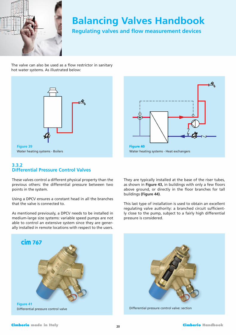
Thevalvecanalsobeusedasaflowrestrictorinsanitaryhotwatersystems.Asillustratedbelow:
3.3.2DifferentialPressureControlValves
Thesevalvescontroladifferentphysicalpropertythantheprevious others: the differential pressure between twopointsinthesystem.
UsingaDPCVensuresaconstantheadinallthebranchesthatthevalveisconnectedto.
Asmentionedpreviously,aDPCVneedstobeinstalledinmedium-largesizesystems:variablespeedpumpsarenotabletocontrolanextensivesystemsincetheyaregener-allyinstalledinremotelocationswithrespecttotheusers.
Theyaretypicallyinstalledatthebaseoftherisertubes,asshowninFigure43,inbuildingswithonlyafewfloorsabove ground, or directly in the floor branches for tallbuildings(Figure44).
Thislasttypeofinstallationisusedtoobtainanexcellentregulating valve authority: a branched circuit sufficient-lyclosetothepump,subjecttoafairlyhighdifferentialpressureisconsidered.
BalancingValvesHandbookRegulatingvalvesandflowmeasurementdevices
Figure41Differentialpressurecontrolvalve
767
Figure39Waterheatingsystems-Boilers
Figure40Waterheatingsystems-Heatexchangers
Figure40
Differentialpressurecontrolvalve:section
767767

21 Cimberio Handbook Cimberio made in Italy
BalancingValvesHandbookRegulatingvalvesandflowmeasurementdevices
Figure42Electronicdifferentialpressurecontrolvalve
771
Figure43Differentialpressurevalveontheriser
Figure44Differentialpressurevalveonthemanifold
Electronicdifferentialpressurecontrolvalve:section
Figure42Figure42Figure42Figure42
771

22 Cimberio made in Italy Cimberio Handbook
Figure46Authority
Forthevalvetoeffectivelyperformtheregulationactionitmusthaveauthority inthecircuittobecontrolled,orratheritmustcreateapressuredropthatiscomparabletothatoftherestofthecircuittoberegulated.
Alowauthoritycausesalinearvariationtotheflowratewithopeningof the stem,whileahighauthority (>0.5)causesanon-linearpercenttypeopening.
Nowlet’sconsideringthesamecircuitwithadifferentialpressurecontrolvalveinstalledandthe∆psetat44kPa.
In this situation the circuit to be controlled will always besubject to the same differential pressure, but what’s moreimportantisthatthe2-wayvalvewillhaveanelevatedau-thority:
Thesameholdstrueforelectronicvalves:
Asnoted,thevalveauthorityisdefinedas:
Where∆p total is intendedtobethetotalpressuredropoftheconcernedcircuittoberegulated,includingthatofthevalve(2-waycontrolvalve,thermostaticvalve).
The2-waycontrolvalvehasamodestpressuredropwithrespecttothecircuittobecontrolled,andtheauthorityvalueis:
Thevalvehasalmostlinearcharacteristics,asseeninthegraph:
Figure46
ß===0.167∆pvalve∆ptotal
20120
ß===0.455∆pvalve∆ptotal
2020+24
∆pvalve∆ptotal
ß=
BalancingValvesHandbookRegulatingvalvesandflowmeasurementdevices
Figure45BranchwithoutDPCV
Figure47BranchwithDPCV
Figure48BranchwithEPCV

23 Cimberio Handbook Cimberio made in Italy
Figure51PICVstructure
3.3.3PressureIndependentControlValves
Asmentionedinthepreviousparagraph,thePICVsareacombinationofthreevalves:
DPCV;Regulatingvalve;2-waycontrolvalve.
Thestructureofthevalvecanbeseeninthefigure.
The fluid passes through the adjustable opening of themodulatingcontrolcomponentandactsagainstthepushofthespringinstalledinthecartridge,balancingtheforceandchangingthesectionoftheoutletholes.
Usingtheactuatororthemanualcommand,theflowratecanbeshutteredbasedontheneeds.
Thepreviousdiagramsshowatwo-wayvalveforcontrol-lingtheflow,aregulatingvalveandtheDPCVtoregulatethemaximumflowrateandtoadjustitbasedontheca-pacitytotransmittotheclimatizedrooms.Workingoutthepositionof thecomponentsused,wecangetadia-gramlikethis:
Thepreviousdiagramsshowatwo-wayvalveforcontrol-lingtheflow,aregulatingvalveandtheDPCVtoregulatethemaximumflowrateandadjustitbasedonthecapac-itytotransmittotheclimatizedrooms.Workingoutthepositionofthecomponentsused,wecangetadiagramlikethis:
Figure49Pressureindependentcontrolsystem
Figure49 Figure50BranchwithPICV
Figure52CimberioPICV
777
Pressuretestpoint
DPCV2-portvalve
andDRV
Figure52CimberioPICV
777
and

24 Cimberio made in Italy Cimberio Handbook
0,0000
0,1000
0,2000
0,3000
0,4000
0,5000
0,6000
0 50 100 150 200 250 300 350
FLO
W R
ATE
(l/s
)
DIFFERENTIAL PRESSUTE (kPa)
Pre-set 0,5
Pre-set 1,0
Pre-set 1,5
Pre-set 2,0
Pre-set 2,5
Pre-set 3,0
Pre-set 3,5
Pre-set 4,0
BalancingValvesHandbookRegulatingvalvesandflowmeasurementdevices
3.3.3.1Operatingprinciples
Regulation
When theelectric actuatororplastic cap ismissing, thevalve is normally closed by a swing. on the contrary, iftheplasticcapisscrewedortheelectricactuatorinstalledtherein,theywintheforceoftheswingandopenthevalve(seepicture).Theinletwatergoesthroughamodulatingcontrolcomponentwhosegeometrycanbemodifiedbyturningthepresettingdial,accordingtotherequiredflowrateinthesystembranchwherethevalveisinstalled.
Control
TwodifferentpressuresoperateontheDPCcartridge.Thefirstone is transmitted through thepassage connectingthevalveinlettothelowersectionof“p+”cartridge(seehydraulicschemepicture46);thesecondoneisregisteredatvalveoutletbytheflowrateselectingdevice“pa”.In order to keep constant the difference between thementionedpressures, theDPC cartridgeobturatoroper-atesbyclosingthewateroutletboretoreachthepresetflowrate,regardlessoffluctuatingpressureconditionsofthesystem.
ThegraphbelowshowsthecharacteristiccurvesofaPICVforthevariouspresetpositions.
Figure53PICVlayout
Figure53
Figure54FlowratevsDifferentialpressure
Flowrate-Differentialpressure
Modulation
Theelectricalactuatorperformsthemodulatingfunctionchangingthesectionofflowpassage.Whencontinuousmodulation is carried out, the temperature is kept un-der control.Thevalvekeeps the sameobturator stroke,regardlessof thepresettingdialposition.With continu-ousmodulation,controlisexcellentevenwithsmallflowopening.Thiseliminatetheon/offeffect.

25 Cimberio Handbook Cimberio made in Italy
4.Designconsiderations
4.1Self-balancingarrangements
Bycarefulsizingofpipes,flowratescanbemadetoap-proximately achieve a self-balance. A self-balancing ar-rangement will reduce the time required to regulatebranchflowratesandwilloftenmakeitunnecessarytobalanceflowsthroughterminalunits.However,thereareusuallycostandperformancepenaltiesthatmustbetak-enintoconsiderationwhenattemptingthissolution.
The self-balancing characteristics of a pipe distributionsystemmaybeimprovedbyconsideringthefollowingde-signoptions:
Reversereturn
Asimple reverse return layout is shown inFigure55. Inorderforthistypeofsystemtoself-balance,eachoftheterminalcircuitpressuredropsmustbeequal.Henceeachcircuit requires identical terminal units and similar pipelengthsandfittings.
Furthermore,opposingpressurelossesintheflowandre-turn mains must also be kept as similar as possible. ForexampleifthepressurelossinABvariessignificantlyfromthepressurelossinCDthentheself-balancingpropertiesmaybelost.
Reversereturnsystemsinvariablyinvolveextrapipework
sincealongerrunofreturnpipeisrequiredtocompletethecircuit.Thiscanincreasetheoverallcostofthesystemandincreasesystemresistanceleadingtohigherpumpen-ergyconsumption.
Itisthereforeimportanttoensurethattheuseofreversereturn systemscanbeeconomically justified incompari-sonwithaconventionallayoutwithregulatingvalves.
Lowlossheaders
Incircuitsbasedon lowlossheadersthe idea is tokeepthepressure loss inthemainsas lowaspossiblesothatthepressuredifferentialavailabletoeachcircuitisrough-lythesame.
Inorderforthisarrangementtoworktheterminaldeviceshavetobeidentical i.e.thesameflowrequirementandthesameresistancetoflowrate.Lowlossheadersrequirethatpipe circuits are sizedoneor two sizes larger thanwouldnormallybethecase.
Calibratedvalves
Itispossibletocalculatethetheoreticalpressurelossre-quiredacrossaregulatingvalveinordertoregulatetheflowratesinthesystem.Fromthesevaluestheindividualsettingsofeachregulatingvalvecanbepredicted,therebyavoidingtheneedforaproperflowbalancingprocedure.
Inpractice,anybalanceachievedinthiswayislikelytobeextremelycrudewiththepotentialforlargevariationsinflowrate.Thisisbecausethetheoreticalresistancesofcom-ponentsarenotveryaccurateandthemanufacturer’spres-surelossdatamaynotalwaysbeuptodate.
ManifoldDistribution
Manifolddistributionencouragesself-balancingbycreat-ingroughlyequalpressurelossesacrosseachcircuit.Thepressure differential across each circuit is the same be-causethemanifoldportsareveryclosetogether.Inordertotakeadvantageofthisproperty,thesuppliedterminalcircuitsmustagainbeas similaraspossible i.e. identicalterminalunitsandsimilarpipelengths.
Figure55Reversereturnlayoutforterminalbranches
BalancingValvesHandbookDesignconsiderations
AB
C D

26Cimberio made in Italy Cimberio Handbook
4.2Velocities
Flowvelocitieswillbedeterminedbythechosenrangeofacceptablepressuredropspermetreofpipelength(typicallybetween100and350Pa/mformaindistribu-tionbranches).However, it isdesirabletoachieveve-locitieswithin the rangeof the recommendedvaluesgiveninTable2.
Very low velocities may reduce the accuracy of flowmeasurementdevicesandcouldfailtopreventtheoc-currenceofstaticairpocketsinthesystem.
4.3Pumpselection
The design of a multi-circuit water distribution systemshouldincludeacalculationofeachcircuit’sresistanceatthedesignwaterflowrate.Thecircuit that ispredictedtopresentthegreatestresistance isknownasthe indexcircuit.Usually,butnotalways, this is thecircuit servingtheterminalunitslocatedfurthestfromthepumpsource.Apumpshouldbeselectedtooperatewithinthestablepart of its characteristic, and be capable of producingbetween110%and115%ofthetotaldesignflowagainsttheestimatedindexcircuitresistance.
4.4Variablespeedpumps
It is sometimes argued that systems which use variablespeedpumpsand2-waycontrolvalvesdonotrequireflowregulation.Thebeliefisthatoncethe2-wayvalvesbeginto closedown,anyflowbalanceachievedwhen the sy-stemwasfullyopenwillbelost.
BalancingValvesHandbookDesignconsiderations
Excessiveflowvelocitiesmaygiverisetonoisegenerationanderosionofsystemcomponents.
Table2Recommendedrangeofwatervelocities
Furthermoreifsystemflowratesareoutofbalancethenthesystemwillgraduallyself-compensate,sincehighflowregions will heat up or cool down more quickly; then,whenthe2-wayvalvesclosedown,flowwill increase inpartsofthesystemthatwereoriginallystarvedofflow.
Inrealitythisargumentdoesnotholdup.Asystemwithunbalancedflowswilltakemuchlongertoreachdesigntemperatures.Areasthatarereceivingtoomuchflowwillnotreachtheirdesigntemperaturesverymuchfasterthaniftheflowswerecorrect.
This isbecause theheat transferacrossmostemitters isrelativelyinsensitivetolargeincreasesinflowrate.Hencethe flow could be double its design value but the heattransfermayonlybe10%more.Theconsequencewouldbeasystemthatwouldtakemuchlongertoachieveuni-formtemperaturesaroundthebuildingandwhichwouldneedtooperateformuchlongerperiods.
4.5Systemcleanliness
Dirtinthesystemcanadverselyaffecttheaccuracyofflowmeasurementdevicesandthereforesystemcleanlinessisofprimeimportance.Adequatefacilitiesmustbebuilt-inatthedesignstagesothatthesystemcanbeflushedtoremove dirt and jointing materials. Where appropriate,strainersshouldbelocatedtotrapcirculatingdirtparticlesbefore they reach small diameter regulating valves andcontrolvalves.
4.6Ventinganddraining
Airtrappedwithinapipeworksystemcanpresentseriousproblemsduringregulationbydistortingmeasuredflowrates.Thesedistortionsmaybeduetopumpsurging,cau-singrapidlyvaryingflowrates,orairbindingofterminalunits causing apparent blockages. Alternatively, systemairmaycausefalsereadingsatflowmeasurementdevicesduetoairpocketsinthepressuretappingpoints.
Featuresmustbebuiltintothepipeworksystemtoenablealltheairtobevented.Thesefeaturescantaketheformofairbottles,witheithermanualorautomaticairvents,orsimpleaircocksatthehighpointsinthesystemandatallplantitemsandterminalunits.
VELOCITY(m/s)PIPEDIAMETER
(mm) Minimum
Copper/Steel
0.6
1.25
15-50
oVER50
Copper
1.0
1.5
Steel
1.5
3.0
Maximum

27 Cimberio Handbook Cimberio made in Italy
4.7Access
Adequatespaceisnecessary,notjustforinstallationbutalsotopermitaccessforcommissioningandmaintenance.Attentionshouldbegivenatthedesignstagetoensurethatserviceductsandarchitecturalfeatures,suchasfalseceilings,willbe compatiblewith theanticipateddegreeofaccessibility.
Accesstoflowmeasurementdevicesandregulatingvalvesshouldbeaprimeconsideration.Inparticular:
at least 100 mm clearance from pressure test pointsmustbeallowedtoenablethemanometertubestobeconnectedwithoutbending;
access to double regulating valves must be such thatscalesandmarkingsareclearlyvisible;
thethicknessofpipeworkandductworkinsulation,andthesupportandbracketingarrangementsmustbean-ticipated;
thepositionsofaccesspanelsinfalseceilings,etc.mustbe properly co-ordinated with the flow measurementdeviceandregulatingvalvepositions.
5.Guidelinesforvalveselection
Thefollowinggeneralguidelinesareprovidedtoassistthedesignerintheselectionandapplicationofflowmeasure-mentdevicesandregulatingvalves.
5.1Terminology
Whenselectingvalvesitishelpfultounderstandthecom-monterminologythat isappliedtoregulatingvalves. Inparticularkvvaluesandkvsvalues.
Kv
Thekvvaluerepresentstheflowratethroughafullyopenvalveatatemperaturebetween5°Cand40°C,andmea-suredincubicmetresperhourthatwillinduceapressurelossof1bar(100kPa).Hencethekvvalueiseffectivelyameasureofthevalve’sresistance.
Whereavalveisclosecoupledtoaflowmeasurementde-vice,thekvvaluerepresentstheresistanceacrossthefullyopenvalveandflowmeasurementdevicecombined.
BalancingValvesHandbookGuidelinesforvalveselection
UsingSIunits,thepressuredropacrossafullyopenvalvecanbecalculatedfromtheequation:
whereQ=flowrateinl/s,and∆P=pressurelossinPa.
kvvaluesexpressresistanceasaninverse-inotherwordsthegreaterthevalve’sresistancethesmalleritskvvalue.Designengineersaremoreusedtothinkingofresistanceintermsofthepressurelosscoefficient(zeta).Thepressu-relossthroughanyfittingorcomponentcanbecalcula-tedfromtheequation:
wherep=fluiddensity inkg/m3,v=velocity inm/sand∆P=pressurelossinPa.
Thehigher thepressure loss coefficient, thegreater theresistanceof thefitting. For convenience, thisguideex-pressesfullyopenvalveresistancesintermsofbothkvandvaluesbasedonvelocitiesinmildsteelpipes.
Kvs
This term applies to the pressure differential across thetappingsonaflowmeasurementdevice.The“s”denotes“signal”,sinceitrelatestothepressurelosssignalmeas-ured by the commissioning specialist. For a given flowmeasurementdevicewithaknownkvsvaluethecommis-sioningspecialistcancalculateflowratefromthepressurelosssignalusingthefollowingequation:
whereQ=flowrateinl/s,and∆P=pressurelossinkPa
(the overall pressure drop through the device). Becausethereisanincreaseinstaticpressuredownstreamoftheorifice, theoverallpressure loss is actually less than themeasuredpressuredropacrossthetappings.Todetermi-netheoverallpressurelossthroughaflowmeasurementdevice,useitspressurelosscoefficient()inEquation2.
∆p=·p·v2
2
p=·
Q=·∆pkvs36
∆p=1.296·10·6 ( )2Q
kv
Equation1
Equation2
Equation3
device,useitspressurelosscoefficient()inEquation2.

28Cimberio made in Italy Cimberio Handbook
BalancingValvesHandbookGuidelinesforvalveselection
5.3Selectionprocedure
1.Produce a system schematic diagram illustrating howthepipesinterconnecttoprovidefluidflowtoeachter-minalunit.
2.Fromheatingandcoolingloadcalculations,determinethedesignflowratesforallpartsofthesystem.
3.Identifysuitablelocationsfordoubleregulatingvalves.Valves must be provided in the system wherever it isnecessary toadjust theflowrate.Thiswillusually in-cludethefollowinglocations:
a.primary headers, main risers, branches and sub-branches;
b.terminalbranches;c. by-passesfrom3-waycontrolvalves;d.pumpsets;e.boilersandchillers(especiallywhereunitsareinpar-
allel);f. zone control circuits incorporating a secondary
pump.
4 Fromthevalveselectiontable(seetheexampleinTable4),selectthevalvewhoseminimumflowrateisclosestto,butlessthan,thedesignflowrate.
Ifpipeshavebeen sized inaccordancewithinnormalvelocityandpressurelosslimits,thentheselectedvalvewillhavethesamediameterastheadjoiningpipes.
5.2Selectioncriteria
When sizing fixed orifice double regulating valves, thefollowingissuesshouldbetakenintoconsideration.
1.Valvesshouldbesizedtomatchthesizeoftheadjoin-ingpipewheneverpossible.Cimberioregulatingvalvesaredesignedtoaccommodatestandardflowrangesforgivenpipe sizes.Dropping toa smaller than line sizevalvecouldriskhighpressure lossesandexcessiveve-locitiesthroughthevalve.
2.Priortosizingtheflowmeasurementdevice,thetypeof instrument to be used for measuring the pressuredifferentialmustbeconsideredandtheupperworkinglimitspecifiedaccordingly.Therangesoftypicalinstru-mentscommonlyusedformeasurementofpressuredif-ferentials,areasfollows:
a.mercurymanometer: 1to65kPaor0to125kPa;b.flurocarbonmanometer: 1to4.6kPaor0to8.8kPa;c. differentialdigitalmanometer/flowmeter: 1to150kPa.
3.Flowmeasurementdevicesshouldbeselectedandsizedtomeetthefollowingrequirementsatthedesignflowrate:
a.theminimumpressure:differentialsignalshouldbenotlessthan1kPa;
b.double regulating valves should be selected to en-surethattherequiredpressuredropoccursatvalvesettingsnotlessthan25%open(tominimisetheriskofdirtblockage).
Table4ValveselectiontableDN15
DN(mm)
Minimumflowrate
(l/s)Model
MaximumBalancingPressure
(kPa)
kv kvs
15
0.015
0.028
0.055
–
–
0.015
0.028
0.055
0.028
721L
721M
721S
727L
727S
737L
737ML
721
7737S
–
–
–
542000Q2
2366Q2
542000Q2
542000Q2
2366Q2
2366Q2
414.6
92.1
21.9
65.8
7.1
480.4
157.9
29.4
100.4
–
–
–
1.278
3.905
0.473
0.825
1.911
1.035
0.473
0.976
1.799
–
–
0.473
0.976
1.799
0.976Figure56ResidualPressure
Circuit1residualpressure=∆Pindex-∆Pcircuit1
∆Pcircuit1 ∆Pindex

29 Cimberio Handbook Cimberio made in Italy
5.Havingselectedthevalves,calculatethepressurelossesacrossthosevalvesintheindexcircuit.Thesepressurelossesneedtobetaken intoaccountwhensizingthepump. To calculate the pressure drop across the fullyopen valve use the equations provided under section5.1above.
6.For thosevalves thatareat thebeginningofbranch-esorwhichareclosetothepump,checkthatthede-signpressure losses across themwill notexceed theirmaximumbalancingpressure.Thedesignpressuredropacrosseachvalveissometimesreferredtoastheresid-ualpressureandisthedifferencebetweenthepressuredroparoundthefurthestbranchandtheoneinques-tion.Figure56 explainshow residualpressure canbecalculated.
7.Havingcalculatedtherequiredresidualpressure,checkthatitsvalueislessthanthevalve’smaximumbalanc-ing pressure. The maximum balancing pressure is thepressuredropacrossthevalveatits25%openposition.A simple equation to calculate the maximum balanc-ingpressureforeachvalvecanbereadfromTable3.Iftheresidualpressureexceedsaparticularvalve’smaxi-mumbalancingpressure,itmaybenecessarytoselect2valves,andinstalltheminseriessothateachonecanremovehalfofthetotalpressureloss.
BalancingValvesHandbookGuidelinesforvalveselection
8.Havingselectedallofthevalves,theselectioninforma-tion shouldbe recorded in the formofa table cross-referenced to the relevant specification clauses anddrawings.Theinformationshouldinclude:
a.manufacturer’smodelandreferencenumbers;b.valvesizesandkvorkvsvalues;c. intendedlocations;d.designflowrates;e.anticipatedpressurelosssignalsatdesignflowrates.
5.4Softwareforselection
Manualsizingiscertainlynotverypractical.Thereiscal-culationsoftwareavailable,suchasCIMsize,thatcansizethevalvequicklyandeffectively,thusreducingthechanceoferror.
Theprogramscanalsocreateusefulreportsforcommis-sioningthesystemandthespecificationswiththenumberandtypeofvalvesrequired.
Figure57CIMsize1.0
screenshot

30 Cimberio made in Italy Cimberio Handbook
Figure58Fluorocarbon/mercurymanometer
6.Measuringflowrate
Inordertoestablishtheflowratethroughafixedorificedouble regulating valve it will be necessary to measurethepressuredifferentialacrosstheorifice.Havingmeas-uredthepressuredifferential,andknowingtheorificekvsvalue,theflowratecanthenbecalculatedusingthefol-lowingequation:
whereQ=flowrateinl/s,and∆P=pressurelossinkPa
Alternatively, forCimberiovalves,flowratecanbereaddirectly from pressure loss versus flow rate graphs con-tainedintheCommissioningValvebrochure.
Pressuredifferentialcanbemeasuredusingamanometer.Thetwomostcommontypesofmanometerinusearethefluorocarbon/mercurymanometerandtheelectronicdig-italmanometer.Thefunctionandoperationofthefluoro-carbon/mercurymanometerisdescribedinthefollowingsection.
6.1Fluorocarbon/mercurymanometer
The fluorocarbonormercurymanometer indicatespres-surebytheheightofacolumnof fluorocarbonormer-cury.Theinstrumentissimple,hasnomovingparts,andregularcalibrationisnotrequired.Providedcertainbasicproceduresarefollowed,theinstrumentwillgivereliableandreproduciblereadings.
Agoodqualitymanometerwillhave the following fea-tures:
alargefluidreservoirwithmeansofzeroadjustment;a safety chamber to reduce the risk of blowing themercuryoutofthemanometeriftheinstallationpres-sure is greater than the range of the manometer;interchangeable connections for use on various pipeandflowmeasurementdevicetappings;
sealable couplings to prevent loss of water from themanometerlines;
avalvechamberforpurgingairoutofthemanometerandassociatedpipework;
BalancingValvesHandbookMeasuringflowrate
colour coded high and low pressure connecting lines(red/highpressure,blue/lowpressure).
The following routine is used when setting up to takemeasurements with the fluorocarbon/mercury manom-eter:
1 Ensure that the manometer and hoses are suitableforthestaticpressureandtemperatureinthesystem.Thisisparticularlyimportantwithdifferentialpressuremeasurement.Thedifferentialmayonlybesome6kPabut the pressure with respect to atmospheric on themanometercouldbeinexcessof500kPainahighrisebuildingorpressurisedhightemperaturehotwatersys-tem;
2 Ensure that the manometer is of a suitable range tomeasure the anticipated maximum differential pres-sure;
3 Supportthemanometerfirmlyinaverticalpositionsothatitcannoteasilybedislodged;
4 Ensurethatallthemanometerchamberby-passvalvesaresecurelyclosed;
5 Connect theappropriatecouplings (binderprobes) tothemanometerlines;
6 Connect the manometer to the high pressure side oftheflowmeasurementdevice;
Q=·∆pkvs36

31 Cimberio Handbook Cimberio made in Italy
Figure61SoftwarePcomPRoforCIMDRoNIC726AC6
Figure59DigitalmanometerCIMDRoNIC726DM10
726
7. Holdingthelowpressuremanometerlineoverabuck-etordrain,openthemanometerby-passvalve;
8. open the low pressure and high pressure chambervalvesandallowwatertoflowthroughtheconnect-inglinesandintoabucketofwateruntilallairbub-blesareexpelled;
9. Isolatethemanometerlinesfromtheflowdevicebyclosing the by-pass high pressure and low pressurevalves.Connectthelowpressurecouplingtothelowpressuretestpoint,openitsisolatingvalveandthenreopen the by-pass valve. Zero the manometer bymovingthescaleagainstthemeniscus.
10.Re-openthehighpressureandlowpressurevalves;
11. Slowlyclosetheby-passvalve,watchingthefluorocar-bon/mercury.Whenthevalveisfullyclosedthediffer-entialpressurecanberead;
12.Todisconnectthemanometeropenthebypassvalve,close the high pressure and low pressure chambervalves, re-close the bypass valve. Close the isolatingvalves on the pressure points, then carefully discon-nectthemanometerlinesfromtheflowmeasurementdevice.
BalancingValvesHandbookMeasuringflowrate
6.2Digitalmanometer
Electronicshaveallowedmeasuringequipmenttoimprove,reducingtheirvolumesandweights.Therearedevicesavail-able that can measure both the differential pressure andcalculatetheflowratecirculatinginthevalve(byinsertingtheKvvalue).TherearealsotrueCommissioningunitsthatnotonlycanmeasurepressure/flowrates,butsystematicallyplanandperformthecommissioningofthesystem.
Theseunitshavealargedatabasewiththeavailablebalanc-ingvalvesandcaneasilyperformtheproportionalbalanc-ing,storingallthemeasuredflowratesforeachvalveinareport.Theseflowratescanberecalculatedbythesystemdesignerinordertoverifythecalculationmodelusedand,ifnecessary,interveneifthereareanyanomalies.
Ausefulsoftwareprogramisalsoavailablethatschedulesthecommissioning,generatingareportthatprovidesalloftheinformationinordertoperformthecorrectbalancingofeachvalve.
DM10
Figure60DigitalmanometerCIMDRoNIC726
726AC6

32Cimberio made in Italy Cimberio Handbook
BalancingValvesHandbookFlowregulationprocedure
7.Flowregulationprocedure
Theon-siteregulationofawaterdistributionsystemin-volvestwobasicprocesses:
1.Theadjustmentofbranchregulatingvalvestoobtainflowratesthatareincorrectratiotoeachother.Thisisachievedbythetechniqueofproportionalbalancing.
2.Theadjustmentofthetotalflowrategeneratedbythepumptoobtainthedesignflowrate.Thisisachievedei-therbythrottlingdownthepumpregulatingvalve,byvaryingthepumpspeed,orbysubstitutingthepumpimpeller,asappropriate,andasagreedwiththedesignengineer.
7.1Fluorocarbon/mercurymanometer
The technique of proportional balancing is accepted asthe most appropriate method of effectively regulatingdistributionsystems.
Considerabranchpipe(Figure59)withseveralterminalunits.Theflowofwaterthrougheachterminalrepresentsacertainproportionorpercentageofthetotalflowinthebranch.
Figure62Basisforproportionalbalancing
Unlesstheterminalbranchregulatingvalvesarealteredthese proportions will remain the same, whatever theflowrateinthemainpipe.
Tobalanceoneterminalunitagainstanother,therefore,itisonlynecessarytoadjusttheregulatingvalvessothattheterminalunitssharetheflowinthecorrectproportions.Itdoesnotmatterwhattheactualflowrateisatthetime.Whenthemainflowfromthepumpisregulatedtoitsde-signflowrate,eachterminalunitshouldalsobepassingitsdesignflow,sinceeachhasbeensettotakeitscorrectproportion.
7.2Indexcircuit
Theindexcircuitisthecircuitthat,withthesysteminanunbalancedstate,exhibitsthegreatestresistancetoflow.Itcanbeidentifiedbycalculationasthecircuitwiththehighestpressurelossarounditwhendesignflowratesareassumed. on site it can be identified by flow measure-mentasthecircuitforwhichtheratioofmeasuredflowtodesignflowrateislowest.
All systems have a single overall index circuit againstwhichthepumppressureiscalculated.
Furthermore,foranybranchservingsub-branches,therewill be an index sub-branch. Similarly each sub-branchmayserveanumberofterminalbranches,oneofwhichwillbetheindexterminalbranch.
If all branches are of equal resistance, the main systemindex circuit is likely to be from the pump to the mostremote terminal, since this circuit has the longest pipelengths.Similarly,sub-branchindexcircuitsarelikelytobefromthestartofthesub-branchtothemostremoteter-minaltheyserve.However,ifterminalbranchresistancesvary then the system indexandbranch indexeswill notnecessarilycoincidewiththemostremoteterminals.Thelocationofeachindexwillthendependonwhichcircuithasthehighestcombinationofpipeandterminalbranchpressurelosses.
Asthecircuitstartingwiththehighestresistance,thereisnoneedtoregulateflowatanindex.Attheendofthebalancingprocess,theindexcircuitshouldalwayshaveafullyopendoubleregulatingvalve.
Initialflowrate0.4l/s
Finalflowrate0.8l/s
0,08l/s20%
0,16l/s20%
0,10l/s25%
0,20l/s25%
0,10l/s25%
0,20l/s25%
0,12l/s30%
0,24l/s30%

33 Cimberio HandbookCimberio made in Italy
7.3Proportionalbalancingprocedure
Thebalancingproceduremustalwaysstartfromthemostremotebranchandworkbacktowardsthenearest.HenceforthesystemshowninFigure60,Theflowratestoter-minalbranchesT3,T2andT1wouldeachbebalancedinturnagainsttheflowattheindex,T4.
Thebalancingprocedureisasfollows:
1.Usingthefixedorificedeviceatthemainbranch,meas-urethetotalflowenteringthecircuit.Ensurethatthisflowrateisbetween110%and120%ofitsdesignflowrate.Itmaybenecessarytoclosedownotherbranchestoachievethis;
2.Usingthefixedorificedeviceoneachterminal,meas-ure the flowrates througheach terminalbranch.Foreachterminalbranchcalculatethe%designflowrate:%designflowrate=(measuredflowrate/designflowrate)x100. Ifthesignalsatanyoftheflowmeasure-mentdevicesarebelowthemeasurementrangeofthedevice (i.e. less than 1kPa), further increase the totalflowrateenteringthebranchbyclosingdownadjacentbranches;
3.Identifytheindexterminalbranch.Thiswillbetheonewith the lowest % design flow rate. Usually, but notalways thiswillbe theendbranch (furthest fromthepump). If theendbranch isnot the index, thencloseits regulatingvalveuntil its%designflowrate isap-proximately 10% less than that at the true index (sothattheendbranchbecomesanartificial index).Thisneedstobedonewhilesimultaneouslymeasuringtheflowinthetrueindex,sinceitsflowwillchangeastheendbranchisadjusted;
BalancingValvesHandbookFlowregulationprocedure
4.Connectamanometertothefixedorificedeviceintheendterminalbranch.Workingbacktowardsthenear-est branch, adjust each terminal branch regulatingvalveuntilits%designflowratebecomesequaltothatattheendsub-branch.Thisneedstobedonewhilesi-multaneouslymeasuringtheflowrateattheendsub-branchsinceitsflowwillchangeasupstreamvalvesareadjusted;
5.Havingachievedequal%designflowratesforeachofthe sub-branches, the sub-branch flow rates are nowbalanced.Thebalancecannotbedisturbedbythead-justmentofupstreamvalves.Hence,upstreambranchescanbebalancedinexactlythesameway;
6.oncetheentiresystemhasbeenbalanced,adjusttheflowfromthepumpto110%ofthetotaldesignflowrate for the system. All branches and sub-branchesshouldnowhaveflowratesclosetotheir100%designvalues.
7.4Reporting
Havingachievedanaccuratebalanceofflowrates,eachofthedoubleregulatingvalvescanbelockedinposition.ForCimberioregulatingvalves,thisisachievedbyopen-ingtheendcaptorevealanAllenkeyoperatedlockingmechanism.By tightening the screw, thevalve is lockedinthesetpositionsothatthevalvecanbeclosed,butonre-openingthevalvewillnotopenbeyondthelockedpo-sition.Hencetheflowbalanceisretained.
Asarecordforfuturesystemdesignchecking,faultfind-ingandmaintenance,itisalsoessentialthattheoriginalvalvesettingsandmeasuredflowratesarerecordedintheformofatable.
Figure63Proportionalbalancingprocedure
T4 T3 T2 T1

34Cimberio made in Italy Cimberio Handbook
BalancingValvesHandbookIndexoffigures
Figure1 Effectsofflowvariation 4Figure2 Effectsofsupplytemperature 5Figure3 Effectsofextraflows 6Figure4 Effectsofflowvariationincoolingsystems 6Figure5 Constantvolumesystem:3-waydivertingvalve 8Figure6 Regulatingofa3-waydivertingvalvesystem 8Figure7 Variablevolumesystem:2-waycontrolvalve 8Figure8 Regulationofa2-waycontrolvalvesystem 9Figure9 2-waycontrolvalvewithregulatingdevice 9Figure10 Example1:smallbulding 9Figure11 Example1:unbalancedsystem 9Figure12 Example1:balancedsystem 10Figure13 Example1:traditionalpump 10Figure14 Example1:variablespeedpump-constanthead 10Figure15 Example1:variablespeedpump-proportionalhead 11Figure16 Example2:layout 11Figure17 Example2:unbalancedsystem 11Figure18 Example2:balancedsystem 12Figure19 Example2:Traditionalpump 12Figure20 Example2:variablespeedpump-constanthead 12Figure21 Example2:Variablespeedpump-proportionalhead 12Figure22 Doubleregulatingvalves 13Figure23 Regulating2-waycontrolvalvewithactuator 13Figure24 Installation 14Figure25 Fixedorificeflowmeasurementdevices 14Figure26 Fixedorificedoubleregulatingvalves 15Figure27 Fixedorificedoubleregulatingvalves:pressures 15Figure28 Fixedorificedoubleregulatingvalves:velocities 15Figure29 Variableorificedoubleregulatingvalves 16Figure30 Variableorificedoubleregulatingvalves:pressures 16Figure31 Variableorificedoubleregulatingvalves:velocities 16Figure32 Impactofflowmeasurementaccuracy onheatingandcoolingsafetymargins 17Figure33 Cartridgeandsection 18Figure34 CFRinconstantvolumesystems 19Figure35 CFRinvariablevolumesystems 19Figure36 CFRwithactuator 19Figure37 Anti-condensation 19Figure38 CFRwithheatexchanger 19Figure39 Waterheatingsystems-Boilers 20Figure40 Waterheatingsystems-Heatexchangers 20Figure41 Differentialpressurecontrolvalve 20Figure42 Electronicdifferentialpressurecontrolvalve 21Figure43 Differentialpressurevalveontheriser 21Figure44 Differentialpressurevalveonthemanifold 21Figure45 BranchwithoutDPCV 22Figure46 Authority 22Figure47 BranchwithDPCV 22Figure48 BranchwithEPCV 22Figure49 Pressureindependentcontrolsystem 23Figure50 BranchwithPICV 23Figure51 PICVstructure 23Figure52 CimberioPICV 23Figure53 PICVlayout 24Figure54 FlowratevsDifferentialpressure 24Figure55 Reversereturnlayoutforterminalbranches 25Figure56 ResidualPressure 28Figure57 CIMsize1.0screenshot 29Figure58 Fluorocarbon/mercurymanometer 30Figure59 DigitalmanometerCIMDRoNIC726DM10 31Figure60 DigitalmanometerCIMDRoNIC726 31Figure61 SoftwarePcomPRoforCIMDRoNIC726AC6 31Figure62 Basisforproportionalbalancing 32Figure63 Proportionalbalancingprocedure 33
8.Index offigures

35 Cimberio HandbookCimberio made in Italy
Table1 Commonvalvetypesandtheirfunctions 5Table2 Pumpstechnologiescomparison 11Table3 Recommendedrangeofwatervelocities 22Table4 ValveselectiontableDN15 25
CommissioningWaterSystems-BSRIA,BG2/2010
2012ASHRAEHandbook-HVACSystemsandEquipment
2011ASHRAEHandbook-HVACApplications
Impiantitermotecnici–prof.GiulianoCammarata
Leretididistribuzione–MarioDoninelli
Icircuitieiterminalidegliimpiantidiclimatizzazione-MarioDoninelli.
9. Index oftables
10.Bibliography
BalancingValvesHandbookIndexoftables-Bibliography

28017 San Maurizio d’Opaglio (NO) - Italy - Via Torchio, 57 - C.P. 106Te l . + 3 9 0 3 2 2 9 2 3 0 0 1 - F a x : + 3 9 0 3 2 2 9 6 7 2 1 6 / 9 6 7 7 5 5
s k y p e : c i m b e r i o s k 1 , c i m b e r i o s k [email protected]
®
www.cimberio.com© Copyright - Cav. Uff. GIACOMO CIMBERIO S.p.A. - All rights reserved. Tutti i diritti riservati. - Stampa: Poligrafica Moderna - Novara - 10/2013 - REV. 02