Self-balancing robot
13
Self-balancing robot A Project Report Group: NING HU ZEXIN LI Under the guidance of VIKRAM KHAPILA (Professor, Department of Mechanical & Aerospace Engineering) in partial fulfilment for the course of ADVANCED MECHATRONICS (ME – GY 6933) for MECHATRONICS AND ROBOTICS ENGINEERING of TANDON SCHOOL OF ENGINEERING 11201, 6 MetroTech Center, Brooklyn, NY 11201
-
Upload
khangminh22 -
Category
Documents
-
view
2 -
download
0
Transcript of Self-balancing robot
Self-balancing robot A Project Report
Group:
NING HU
ZEXIN LI
Under the guidance of
VIKRAM KHAPILA (Professor, Department of Mechanical & Aerospace Engineering)
in partial fulfilment for the course
of
ADVANCED MECHATRONICS (ME – GY 6933)
for
MECHATRONICS AND ROBOTICS ENGINEERING
of
TANDON SCHOOL OF ENGINEERING
11201, 6 MetroTech Center, Brooklyn, NY 11201

contents A Project Report 1
Group: 1
1. INTRODUCTION 2
2. IMPLEMENTATION 2
3. Self-balancing robot 2
3.1 working principle and Software design 2
3.2 model 4
3.3 FILTER 9
3.4 Result and conclusion 10
4. Red ball tracking 10
4.1 General principle 10
4.2 Core code 11
4.3 Communication with robot 11
1. INTRODUCTION To make a robot which can balance itself on two wheels. There will be only one axle
connecting the two wheels and a platform will be mounted on that .There will be another platform above it. The platform will not remain stable itself. Our job will be to balance the platform using distance sensors and to maintain it horizontal. At first we have decided to just balance the robot on its two wheels .If the platform inclines then microcontroller (in this case it is Arduino) will send signals to motors such that motors would move forward or backward depending on the inclination direction and extent. So if the platform tilts forward then motors will run forward and backward to keep the platform horizontal. For this we will need to code the Arduino in order to perform job according to this.
The motor driver is powered by 12V power supply. The PWM sent to the motor driver has low voltage=0V and high voltage=5V. The motor driver L298N scales it to the range low voltage=0V and high voltage=12V (motor driver is used because motors need 12 V to run. Also they need high current. Microcontroller output ports cannot supply 12 V and high current). Then this PWM is applied across the motor .so ,if the robot tilts such that height of sensor 1 decreases , then accordingly output PWM will be such that (output PWM will be positive) motors will run to accelerate the robot to sensor 1 side. Because of this this acceleration robot will experience a torque (due to pseudo force in the non inertial frame) that will oppose the torque due to gravity and it will bring the robot platform back to the horizontal level .Change in the difference value. The modified part of code measures difference (bet sensor1 value and sensor2 value) regularly
after some fixed interval (10 milliseconds). So the change in difference(i.e., difference- previous difference) is considerable. We have not used I (integration) here in the PID control as we found P+D sufficient to balance the robot.
2. IMPLEMENTATION 1 Arduino Uno R3 2 Sensor shield 3 H bridge 4 Dc motor 5 MPU6050 6 Joystick 7 NRF24L01 8 Battery 9 Rasberry PI3 10 Red ball
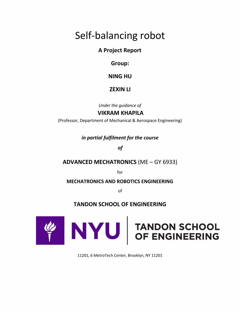
3. Self-balancing robot 3.1 working principle and Software design 1)working principle
2) Software design
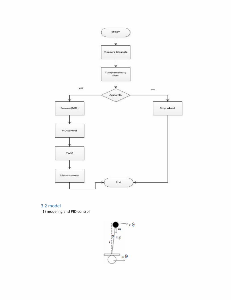
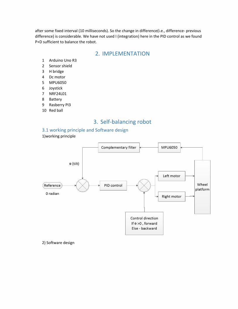
3.2 model 1) modeling and PID control

Fig1 force analysis
According to kinematic balance principle , (a(t) means wheel acceleration)

(1)× ×X(t) ×sin θ(t) (t)×cos θ(t) ldt2d θ(t)2
= l + g − a
Because the range of is close to 0 , .(t)θ in θ(t) ≈θs os θ(t) ≈1c
Therefore , the (1) will be
(2)× ×X(t) ×θ(t) (t)ldt2d θ(t)2
= l + g − a
After Laplace transfer , (because of static , a(t) is equal to 0)
(3)×s ×θ(s) ×X(s) ×θ(s)l 2 = l + g
θ(s)X(s) = l
l×s −g2
Accoreding to (3) transfer function , its pole points are
Sp = ±√ lg
Because one of poloe points are on the right of s-plane , this system is unstable based on nyquist stability criterion.
In order to solve it , PID control is a method .
PID controller is in laplace transfer.kp + SKI + S * KD
The new system model is in the following :
Closed-loop transfer function is θ(s)X(s) = 1
1+(k + +S K )×p SKI * D
ll×s −g2
For this closed-loop system , its pole points (A in the pic is the system transfer function , p means pole points ; Kp=112 , Ki=1.4 Kd=1800)
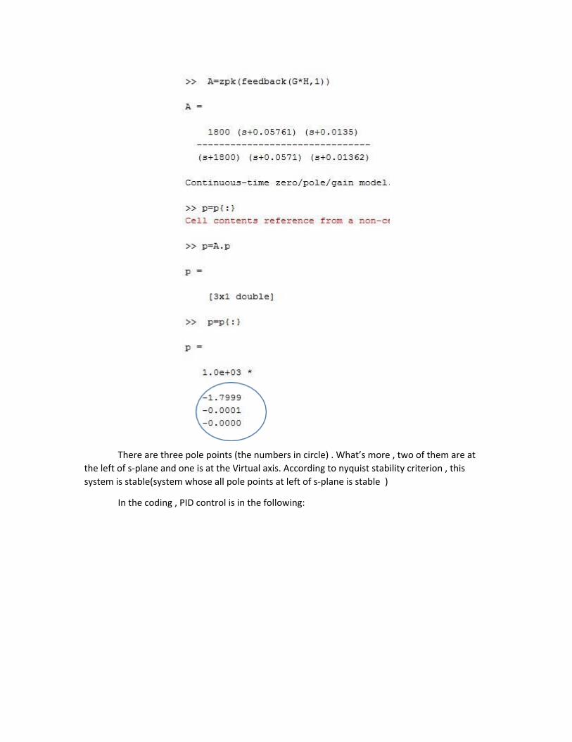
There are three pole points (the numbers in circle) . What’s more , two of them are at the left of s-plane and one is at the Virtual axis. According to nyquist stability criterion , this system is stable(system whose all pole points at left of s-plane is stable )
In the coding , PID control is in the following:


Notice(Turn_speed and Run_speed are controlled by joystick)

3.3 FILTER
In the code , the filter is in the following:

the formula in the square is complementary filter.
3.4 Result and conclusion A self-balancing robot was designed and manufactured as desired with limited
resources possible. It was able to balance smoothly with a maximum tilt error of 5 degrees. Range of payload and its height for which it balances was quantified. Maximum angle of tilt for balancing was also determined through various experiments. However there are some limitations. Such technology is suitable only for flat ground. In order to make it work on slant surface, the angle of slant needs to be fed into the system, either manually or using some intelligence
4. Red ball tracking
4.1 General principle
In order to achieve the performance that the red ball can be followed by the robot but stop when the distance is close enough. Some computer vision work should be carried out.
Red ball tracking based on Open CV platform. By using the HSV image we caputure, Open CV can find the contour of red ball. Then we can aquire the radius of the contour using cv2.minEnclosingCircle() command.
Now the radius has been calculated,then:

if radius > a(red ball is close enough to the camera), do nothing if radius<=a(robot need move forward), transmit a signal from rpi to arduino.
4.2 Core code
Appendix:
cv2.findContours(): find every red area in the image; max(): find the red area with maximum space; minEnclosingCircle(): find a circle that can cover the given area with minmum
area, and return the radius of the circle; cv2.moment: calculate the image moment and find the center of the image.
4.3 Communication with robot

In order to combine the robot with computer vision, the communication is essential. Because we don’t need a heavy job based on the communication, our project apply serial communication between the Arduino borad(Robot part) and Raspberry PI(Open CV part).