Control System in Open-Source FPGA for a Self-Balancing ...
19
electronics Article Control System in Open-Source FPGA for a Self-Balancing Robot Juan Ordóñez Cerezo 1,† , Encarnación Castillo Morales 2,† and José María Cañas Plaza 1, * ,† 1 RoboticsLab-URJC, Rey Juan Carlos University, Fuenlabrada, 28943 Madrid, Spain; [email protected] 2 DiTEC Research LAB, Granada University, 18071 Granada, Spain; [email protected] * Correspondence: [email protected]; Tel.: +34-914-888-755 † These authors contributed equally to this work. Received: 30 December 2018; Accepted: 1 February 2019; Published: 9 February 2019 Abstract: Computing in technological applications is typically performed with software running on general-purpose microprocessors, such as the Computer Processing Unit (CPU), or specific ones, like the Graphical Processing Unit (GPU). Application-Specific Integrated Circuits (ASICs) are an interesting option when speed and reliability are required, but development costs are usually high. Field-Programmable Gate Arrays (FPGA) combine the flexibility of software with the high-speed operation of hardware, and can keep costs low. The dominant FPGA infrastructure is proprietary, but open tools have greatly improved and are a growing trend, from which robotics can benefit. This paper presents a robotics application that was fully developed using open FPGA tools. An inverted pendulum robot was designed, built, and programmed using open FPGA tools, such as IceStudio and the IceZum Alhambra board, which integrates the iCE40HX4K-TQ144 from Lattice. The perception from an inertial sensor is used in a PD control algorithm that commands two DC motors. All the modules were synthesized in an FPGA as a proof of concept. Its experimental validation shows good behavior and performance. Keywords: robotics; open FPGAs; robot control 1. Introduction The most common approach taken for the computing required in technological applications is using software which writes instructions for a general-purpose circuit, such as a Computer Processing Unit (CPU) or Graphical Processing Unit (GPU) [1]. Another option is designing a special circuit for this specific computation, where Application-Specific Integrated Circuits (ASICs) [2] are the traditional hardware implementation for system design. This last alternative requires more effort and has high development costs, but when an application requires real-time processing, such as a video, television, or robotic controller for real-time trajectory generation, the requirements are highly demanding and better met when implemented in hardware. However, in general, applications are more flexible when implemented in software rather than in hardware, especially when they are not computationally demanding or when they are non-critical. The emergence of Programmable Logic Devices (PLD) [3] and reconfigurable devices, such as Field-Programmable Gate Arrays (FPGAs) [4] have changed this scenario. The FPGAs are a well-established technology, not only for prototyping and development, but also as a for ASICs in a growing number of applications, as they offer benefits very similar to those of ASICs, such as high speed and reliability, but without requiring as much resources or costs as the custom ASIC design [2]. In addition, these features go far beyond those possible with microprocessor-based systems, while maintaining similar flexibility thanks to their reconfigurability. Unlike microprocessors, FPGAs perform different operations in parallel, and it is unnecessary to Electronics 2019, 8, 198; doi:10.3390/electronics8020198 www.mdpi.com/journal/electronics
-
Upload
khangminh22 -
Category
Documents
-
view
2 -
download
0
Transcript of Control System in Open-Source FPGA for a Self-Balancing ...

electronics
Article
Control System in Open-Source FPGA for aSelf-Balancing Robot
Juan Ordoacutentildeez Cerezo 1dagger Encarnacioacuten Castillo Morales 2dagger and Joseacute Mariacutea Cantildeas Plaza 1dagger
1 RoboticsLab-URJC Rey Juan Carlos University Fuenlabrada 28943 Madrid Spainjordonezcerezohotmailcom
2 DiTEC Research LAB Granada University 18071 Granada Spain encasugres Correspondence josemariaplazaurjces Tel +34-914-888-755dagger These authors contributed equally to this work
Received 30 December 2018 Accepted 1 February 2019 Published 9 February 2019
Abstract Computing in technological applications is typically performed with software running ongeneral-purpose microprocessors such as the Computer Processing Unit (CPU) or specific oneslike the Graphical Processing Unit (GPU) Application-Specific Integrated Circuits (ASICs) are aninteresting option when speed and reliability are required but development costs are usually highField-Programmable Gate Arrays (FPGA) combine the flexibility of software with the high-speedoperation of hardware and can keep costs low The dominant FPGA infrastructure is proprietary butopen tools have greatly improved and are a growing trend from which robotics can benefit Thispaper presents a robotics application that was fully developed using open FPGA tools An invertedpendulum robot was designed built and programmed using open FPGA tools such as IceStudio andthe IceZum Alhambra board which integrates the iCE40HX4K-TQ144 from Lattice The perceptionfrom an inertial sensor is used in a PD control algorithm that commands two DC motors All themodules were synthesized in an FPGA as a proof of concept Its experimental validation shows goodbehavior and performance
Keywords robotics open FPGAs robot control
1 Introduction
The most common approach taken for the computing required in technological applications isusing software which writes instructions for a general-purpose circuit such as a Computer ProcessingUnit (CPU) or Graphical Processing Unit (GPU) [1] Another option is designing a special circuit forthis specific computation where Application-Specific Integrated Circuits (ASICs) [2] are the traditionalhardware implementation for system design This last alternative requires more effort and has highdevelopment costs but when an application requires real-time processing such as a video televisionor robotic controller for real-time trajectory generation the requirements are highly demanding andbetter met when implemented in hardware However in general applications are more flexible whenimplemented in software rather than in hardware especially when they are not computationallydemanding or when they are non-critical The emergence of Programmable Logic Devices (PLD) [3]and reconfigurable devices such as Field-Programmable Gate Arrays (FPGAs) [4] have changed thisscenario The FPGAs are a well-established technology not only for prototyping and developmentbut also as a for ASICs in a growing number of applications as they offer benefits very similarto those of ASICs such as high speed and reliability but without requiring as much resources orcosts as the custom ASIC design [2] In addition these features go far beyond those possible withmicroprocessor-based systems while maintaining similar flexibility thanks to their reconfigurabilityUnlike microprocessors FPGAs perform different operations in parallel and it is unnecessary to
Electronics 2019 8 198 doi103390electronics8020198 wwwmdpicomjournalelectronics
Electronics 2019 8 198 2 of 19
compete for the same resources Thus incorporation of the FPGA in the industry has been drivenby the fact that FPGAs are the combination of the best features of ASICs and microprocessor-basedsystems Fields in which FPGAs are currently used include medical imaging coding and encryptionaeronautics and defense voice recognition artificial vision and robotics
Thus FPGAs are definitively established in the digital systems market with Lattice SemiconductorCorp [5] Xilinx [6] and Intel FPGA [7] as the main private companies Xilinx which recently signeda large collaboration agreement with IBM and Intel FPGA the new trade name of Altera afterits acquisition by Intel are market leaders FPGA devices generally consist of a regular matrix oflogic blocks and an interconnection network both configurable together with multiple IOs Thehigh-end segment [89] has also integrated specific resources for digital signal processing support fornetworks or embedded microprocessors usually being ARM cores Thus synthesized embeddedmicroprocessors are included in FPGA devices such as Nios II [10] or MicroBlaze [11] More recentlyRISC-V [12] a free and open RISC instruction-set type of architecture has been implemented withinMicrosemi FPGA [1314] Moreover FPGAs have a strong presence in the sector of artificial intelligence[15] providing hardware accelerators in this field that can exceed the performance of GPUs Despitethese advanced features it is worth noting that these are proprietary FPGAs and working with themrequires a large budget that is not always feasible such as in educational applications
ISE from Xilinx and Quartus II from Intel FPGA are proprietary software tools offered by thesecompanies for synthesis and analysis of designs to be implemented into its FPGAs usually using aHardware Description Language (HDL) [16] These software tools enable the developer to synthesizeor compile their designs to examine RTL descriptions to perform timing analysis to simulate thedesigns and to configure the target device using the programmer [17] There are currently two industrystandard HDLs VHDL (very high-speed integrated-circuit Hardware Description Language) [18] andVerilog [19] To compare these two on the one hand VHDL is strongly typed it has the ability todefine custom types it can define multiple signals into one type and the logical statement endings areclearly marked However it is also extremely verbose and needs sensitivity lists and type conversionsOn the other hand Verilog is a compact language performs logical tests on an entire array of bitswith a single operator and is adequate for low-level descriptions closer to the actual hardware Butnevertheless it is a weakly typed language it offers no support of custom types the signal declarationscan be confusing and it has reduced support for asynchronous signals This scenario has forced thesearch and development of new alternatives such as SpinalHDL [20] an open-source high-level calledwhose goal is to use simple elements (flip-flops gates ifcase statements) to create a new abstractionlevel and help the designers to reuse their code Among their advantages over VHDL and Verilog arethe evolving capabilities the reduction of the code size the easy type conversions the loop detectionand that it is free and has a user-friendly IDE
As mentioned previously robotics is one of the application fields of FPGA [21ndash23] Typicallythe implementation of robot intelligence and controllers in FPGAs provides many advantages likereliability and fast operation which allow for better robot control However a large budget is requiredto work with proprietary FPGA software tools and it is not affordable for educational applications suchas educational robotics [24] This paper presents a novel use of open-source FPGAs for educationalrobotics using a new visual language for robot programming Concretely an inverted pendulum realrobot was developed The main characteristics of this implementation and the performed experimentsconfirm the feasibility of this proposal
The rest of the manuscript is organized as follows Section 2 is devoted to the related worksinvolved in open FPGA in robotics and the inverted pendulum while Section 3 describes the designof the self-balancing robot using open FPGA Section 4 presents the experiments where a realimplementation of the self-balancing robot over an open FPGA is carried out confirming the feasibilityof the presented proposal Finally the main conclusions are presented in Section 5
Electronics 2019 8 198 3 of 19
2 Related Works
Three areas provide the context for the proposal in this study the use of FPGAs in robotics theopen FPGA community and the robotic application selected as a proof of conceptmdashthe self-balancingrobot Some key works are also reviewed in this section
21 FPGA in Robotics
Robotics is one of the fastest-growing technological areas in recent years [25] It is based onsystems composed of mechanisms which are able to make movements and execute specific tasks thatare programmable and intelligent Some implementation solutions for digital control systems for robotmanipulators and mobile robots proposed in the literature use hardware technologies such as DSPs ormicroprocessors [26] These solutions allow for real-time control but since the DSP has limited outputports applications for control of humanoid robots for instance are not suitable FPGA technologyavoids this limitation ultimately reducing size and weight and therefore costs In addition due tothe efficient integration of embedded processorsrsquo intellectual properties (IPs) into a FPGA the highlysophisticated algorithms with heavy computations required by robotic controllers can be performedby software in an FPGA Thus many FPGA-based solutions have been implemented in the field ofrobotics such as a static gesture recognition system [21] an algorithm for collision detection betweenOriented-Bounding-Boxes (OBBs) [22] and an embedded robust adaptive controller for mobilerobotics [23] Many different works have shown that FPGA implementation of robotic applications isthe best solution for optimum performance Robotics may generate benefits not only in the industrybut also in classrooms [24] enabling the emergence of new learning systems In addition in a futureworld where robots will be used in almost any activity a learning approach using these systems in theclassroom enables studentsrsquo technological development at an early age facilitating their integrationinto the adult world The following are some of the educational benefits of robotics they driveinitiative and creativity promote greater sociability encourage algorithmic and mathematical thinkingfacilitate teamwork problem solving and active learning and enhance self-esteem However in orderto facilitate educational robotics in the classroom the systems must consider the following elements
bull A high technological integration level is not recommendedbull Robots must be sociable and funbull Programming frameworks should not be complex their functionality should be limited to a
certain extent and they must attract studentsrsquo attention and make them feel comfortable in thecontext
bull It is important for the robot to have a series of sensors and actuators as well as inputs and outputsso that the results are visual
A major obstacle to achieving these features in educational robotics is that most commercialeducational robot platforms are closed Thus robot vendors do not commonly provide support for oldcontrol units or when a deprecated robot requires an update or even simple preventive maintenanceThe manufacturer tends to recommend disposing of such a unit and acquiring a new one It is worthmentioning the well-known LEGO PID control [27] and walking robot [28] Open FPGAs and theirnew graphical IDE tools may help to avoid this obstacle as described in the following section
22 Open FPGAs
Many HDLs as well as FPGA architectures are linked to important companies such as Xilinx andIntel FPGA and working with them entails high development costs Hence not many companies orindividuals can benefit from the advantages of using FPGAs meaning FPGA technology progresses ata slower pace One of the keys to the success of companies like Arduino [29] is the large community ofpeople that stands behind creating new libraries components etc This is mainly due to the low priceof its products and the possibility of finding all the hardware and software on the web To understand
Electronics 2019 8 198 4 of 19
the creation of open FPGA [30] it is important to understand the bitstream that is used to describe theconfiguration with which a specific design will be implemented in a FPGA This detailed bitstreamformat for a particular FPGA is typically owned by the FPGA manufacturer This is why Cliford Wolfdecided to interpret the bitstream of the Lattice iCE40 FPGA devices [5] and developed the IceStormtool [31] a translate software from Verilog and bitstream This translation was possible thanks to theinverse engineering meaning that it is not the usual usage that is given but the inverse Thus there isno longer dependency on any manufacturer and all knowledge is also available From these tools newinterfaces or new applications that were not foreseen by the manufacturer can be created Nowadaysthe focus of the IceStorm project is on HX1K-TQ144 and HX8K-CT256 devices from Lattice iCE40 butsince it is an open project a lot of people are increasing their chances IceZum Alhambra [32] is anFPGA development board including the open FPGA iCE40HX4K-TQ144 from Lattice It is an openhardware that is compatible with the IceStorm toolchain and with Arduino Uno shields Figure 1shows the Icezum Alhambra II Board Important features of this board include the following
bull 12 MHz oscillatorbull Onoff switch to enable or disable digital pinsbull 20 InputOutput 5 V pinsbull 8 InputOutput 33 V pinsbull Micro-B USB to program FPGA from PCbull Reset buttonbull Eight general-purpose LEDsbull TXRX LEDsbull 4 analog inputs available through i2cbull 8 K memorybull Possibility of powering through LIPO battery
Figure 1 Icezum Alhambra II Board
This development board can be implemented with new open tools like IceStudio [33] a graphicalIDE for free FPGAs built on the IceStorm project It provides simple tools to analyze and createbitstream filesmdashthat is the lowest level of implementation for an FPGA Boards with better featuresdo exist but IceZum II Alhambra provides open hardware that can be implemented with free andopen software tools This board was created with the idea of making digital electronics user-friendlyfor young students allowing for a visual language for programming the FPGA [34] fulfilling theaforementioned features required for educational robotics
Electronics 2019 8 198 5 of 19
23 Inverted Pendulum
The inverted pendulum is of one the most famous problems in terms of control theory and systemsdynamics [3536] An inverted pendulum is represented in Figure 2 and consists of a pendulum wherethe center of mass is located above the balancing axis Maintaining an upward equilibrium position isa challenge as this equilibrium position is unstable (a system is more stable when its center of massis closer to the supporting horizontal plane) As the inverted pendulum system is non-linear it iswell-suited for control by fuzzy logic [37] The inverted pendulum system has significant theoreticalvalue since it represents the basis of many complex systems such as biped robot upright walkingbalance control rocket launch vertical control spacecraft attitude control and offshore drilling platformstability control Beyond its theoretical interest the inverted pendulum is also attractive for universityprofessors of engineering and teachers in secondary education In this paper a solution for the invertedpendulum problem is addressed using an open FPGA in order to correct its instability
Figure 2 Representation of an inverted pendulum
3 Self-Balancing Robot
In this section the proposed solution for the inverted pendulum problem through the use of anFPGA in coexistence with a micro-controller is described Several aspects are addressed such as thephysics of the self-balancing robot used in the experiments the calculation of its structure the sensorsand actuators used the control system and the design and manufacture of a Printed Circuit Board(PCB) to solve certain engineering problems
This section begins with a brief high-level description (Section 31) and continues with the detailsof the perception element (Section 32) Subsequently the connection between Arduino and FPGA(Section 33) the PD control on FPGA (Section 34) and a motor block in IceStudio (Section 35) arealso described
31 Design
The hardware design of the inverted pendulum control with FPGA is shown in Figure 3The microcontroller obtains the current angle of the system by means of i2c communication with anInertial Measurement Unit (IMU) sensor In the microcontroller once the current robot vertical angle isread a serial-type communication sends it to the FPGA in a binary format of 1 byte for the integral partand 1 byte for the decimal part Inside the FPGA the robot angle is read and the speed commands tothe motors for correction of the angle are calculated by a basic PD controller A shield with a DC motordriver is connected to the FPGA and provides the possibility of varying the speed and the movementdirection of two DC motors that permit the stabilization of the system
32 Perception
Continuous knowledge of the angle is necessary for its analysis and correction For this purposethe MPU6050 sensor was used and connected to an Arduino Nano by i2c communication In order tocorrect some of the data collection problems such as noise or drift it incorporates an internal processor
Electronics 2019 8 198 6 of 19
(Digital Motion Processor DMP) that executes data fusion algorithms (Motion Fusion) to combinethe measurements of the internal sensors avoiding the necessity of performing the filters externally(Figure 4)
Version January 31 2019 submitted to Electronics 6 of 19
IceZum Alhambra II
P
D
ERRORSet Point0ordm + -
I2C
Microcontroller
Serial communication
Current angle
PWM Signals
Figure 3 Hardware design of the inverted pendulum control with FPGA
ACELEROMETTER
GYROSCOPE
DMP
YAW
PITCH
ROLL
MPU6050
I2C
ACELEROMETTER
GYROSCOPE
MPU6050
12 BIT DATA
12 BIT DATA
YAW
PITCH
ROLL
FILTER COMBINATION
AND CALCULATIONS
I2C
Figure 4 Advantage in the use of DMP
Figure 3 Hardware design of the inverted pendulum control with Field-Programmable Gate Arrays(FPGA)
Version January 31 2019 submitted to Electronics 6 of 19
IceZum Alhambra II
P
D
ERRORSet Point0ordm + -
I2C
Microcontroller
Serial communication
Current angle
PWM Signals
Figure 3 Hardware design of the inverted pendulum control with FPGA
ACELEROMETTER
GYROSCOPE
DMP
YAW
PITCH
ROLL
MPU6050
I2C
ACELEROMETTER
GYROSCOPE
MPU6050
12 BIT DATA
12 BIT DATA
YAW
PITCH
ROLL
FILTER COMBINATION
AND CALCULATIONS
I2C
Figure 4 Advantage in the use of DMP
Figure 4 Advantage in the use of DMP
Electronics 2019 8 198 7 of 19
33 Arduino-FPGA Connection
An integration between the microcontroller and the FPGA allows sequential and parallel tasks tobe distinguished assigning each process to the microcontroller if it the task needs to be sequentialor to the FPGA if the process can be parallelized thus obtaining certain advantages More thanone option exists for the microcontrollerFPGA integration In this work physical coexistence withcommunication between them was chosen They can also be integrated by means of several types ofcommunication Serial communication was selected as the most appropriate type due to the numbers ofpins available in the FPGA The communication would only be unidirectional with the microcontrollersending information to the FPGA about the current angle of the robot in order for the FPGA to analyzeand actuate starting from that angle There are thus two parts in this serial communication fromthe point of view of the microcontroller and from the point of view of the FPGA The sensor readingacquisition in the microcontroller is described in Section 32 while only the communication with theFPGA is analyzed in this section The diagram flow on which the C-code of the microcontroller isbased is shown in Figure 5
Version January 31 2019 submitted to Electronics 7 of 19
33 Arduino-FPGA connection196
An integration between the microcontroller and the FPGA allows sequential and parallel tasks to197
be distinguished assigning each process to the microcontroller if it the task needs to be sequential198
or to the FPGA if the process can be parallelized thus obtaining certain advantages More than199
one option exists for the MicrocontrollerFPGA integration In this work physical coexistence with200
communication between them was chosen They can also be integrated by means of several types of201
communication Serial communication was selected as the most appropriate due to the numbers of202
pins available in the FPGA The communication would only be unidirectional with the microcontroller203
sending information to the FPGA about the current angle of the robot in order for the FPGA to analyze204
and actuate starting from that angle There are thus two parts in this serial communication from205
the point of view of the microcontroller and from the point of view of the FPGA The sensor reading206
acquisition in the microcontroller is described in section 32 while only the communication with the207
FPGA is analyzed in this section The diagram flow on which the C code of the microcontroller is208
based is shown in Figure 5209
Angle obtained in previous process
Angle gt= 0
DIGITAL_PIN = 1
Separation between integer and decimal part
Ser i al pr i nt ( i nt eger _par t BI N) TX
TXSer i al pr i nt ( deci mal _par t BI N)
DIGITAL_PIN = 0
True
False
Figure 5 Diagram flow to send angle
For correct and easy understanding by the FPGA it is necessary to send the represented angle as210
several bytes in binary format not as ASCII codes The Serialprintln Arduino function was discarded211
because it uses ASCII codes and would even send the comma character to separate the integral and212
the decimal part Instead the Arduino function Serialprint(Angle) was used which sends a binary213
number through the serial port The representation and sending of the angle reading was separated214
Figure 5 Diagram flow to send angle
For correct and easy understanding by the FPGA it is necessary to send the represented angleas several bytes in binary format not as ASCII codes The Serialprintlnrsquo Arduino function wasdiscarded because it used ASCII codes and would even send the comma character to separate theintegral and the decimal part Instead the Arduino function Serialprint(Angle)rdquo was used whichsends a binary number through the serial port The representation and sending of the angle readingwas separated into two bytes as shown in Figure 5 The first byte is the integer part (from 0 to 255)and the second byte is the decimal part (from 0 to 100) No comma is sent over the wire In FPGA an
Electronics 2019 8 198 8 of 19
input pin will continuously enter data from the transmission pin so that it can make a correct readingof the byte It is necessary to know
bull When a byte transmission startsbull When a byte transmission endsbull When a bit can be capturedbull When the necessary bits are saved in a buffer until the byte is complete
In order to solve the previous problems and features an intermediate module in IceStudio(Figure 6) was implemented
Figure 6 Appearance of Arduino Nano module in IceStudio
This was implemented in Verilog by two machine states with their corresponding sensitivity listsand the diagram flow represented in Figure 7
SERIAL DATA
FPGA CLOCK
START
DATASIDLE
STOP
bit_ready
BYTE_READY
save_buffer[70]
8 bits in buffer
TRUE
FPGA CLOCK 16200 baud
Generated pulse by process 1 when bit is
ready DATA_BUFFER
BYTE_READY
PROCESS 1 PROCESS 2
Figure 7 Diagram flow for Arduino interface
Electronics 2019 8 198 9 of 19
Two distinct processes were usedProcess 1 This process only provides the next system state at the moment at which it can capture
a bit and save it in the buffer Thus it is necessary to know the speed of the transmission The statesare the following
bull IDLE The process remains in this state until the transmission starts which will then lead to thenext state (START)
bull START The serial transmission protocol begins with a start condition and this state will allowrecognition of when this condition ends in order to start saving bits in the buffer
bull DATA Since the transmission speed is already known and the condition of START in the previousstate has been recognized in this state a flag will change its value when the bit is ready to bestored in the buffer of which Process 2 will be in charge of this storage
bull STOP In addition to a START condition the serial transmission protocol used in Arduino hasa STOP condition This state allows recognition of the time Arduino takes to carry out this lastconditionmdashit will then return to the first state until a new transaction begins
Process 2 This process is activated by Process 1 When Process 1 determines that a bit is availableon the bus to be captured it will set a clock flag on initiating Process 1 through a sensitivity list Anexample flow diagram could be
bull Wait until the sensibility list is activatedmdashthis will indicate that a bit can be capturedbull Bits will be stored in a buffer forming a byte which will represent the integer or decimal part of
the angle at that momentbull When the byte is prepared to be captured by two consecutive modules a channel will be on Both
the outputs and the buffer with the 8 bits and the byte_ready channel will be available
At this point the FPGA is able to differentiate between when it can capture a byte (BYTE_READY)and from where it has to capture the data bus (DATA_BUFFER) However an aspect that is not part ofthe communication itself is that it is important to analyze whether a correct operation is requiredmdashthatis if the microcontroller has been previously told to continuously send the integer and decimal part ofthe angle If this data is not correctly interpreted it is possible that an angle on the FPGA is formed bya decimal part of an angle n and the integer part of the angle n + 1 To do this a module is createdin IceStudio that is capable of ordering these values The appearance of this module in IceStudio isshown in Figure 8
Figure 8 Module to arrange data from Arduino
The final communication system between Arduino and IceZum Alhambra from a POV of theFPGA is represented in Figure 9
Electronics 2019 8 198 10 of 19
Figure 9 Communication between Arduino and IceZum Alhambra
34 PD Control in FPGA
A PID controller can simply be used to control the stability of the system One of the facilitiesprovided by this type of controller is the ease of implementation The flow diagram of the P controllerrsquosbehavior is shown in Figure 10
Integer_part
decimal_part
VELOCITY
OFFSET
KP
Pulse when data is ready
Figure 10 Flow diagram of P control
The most important features are briefly explained as follows
bull Both the integer part and the decimal part are represented as 8-bit data without a sign In order togive greater importance to the integer part there is the option of dividing the decimal part by
Electronics 2019 8 198 11 of 19
100 (Figure 10) or of multiplying the integer part by 100 The first option does not provide goodbehavior due to the digital treatment of the floating comma Thus the second option is preferable
bull The two integer and decimal components are added and then it is multiplied by a Kp constantdefined as a parameter which can be dynamically changed
Referring to the D controller the flow diagram implemented in Verilog is shown in Figure 11
VELOCITY
-
Integer_part 100
decimal_part
DATA1
DATA2
KD
Always data_ready
STATE2
STATE1
Integer_part 100
decimal_part
DATA1
DATA2
Figure 11 Flow diagram of D control
Its implementation is composed of a state machine with two states which will change at eachpulse on the data_ready This means that it will change whenever a new angle is available The Dcontroller is based on its operation on the prediction of future errors The derivative control actiongenerates a control signal proportional to the derivative of the error signal A subtraction (derivedfrom the error in time) is therefore carried out between the current error and the last error Its result ismultiplied by the constant Kd Referring to the closed-loop feedback system Figure 12 shows the finalappearance of the present work developed using IceStudio
Electronics 2019 8 198 12 of 19
Figure 12 Final appearance of the self-balancing in IceStudio
35 Motor Block in FPGA
In order to correct the current angle and obtain the stabilization two DC motors were used Thespeed of the motors was controlled by a PWM connected to the driver motor through the FPGATherefore a PWM module generator whose appearance is shown in Figure 13 is needed
Figure 13 Appearance of PWM module in IceStudio
Figure 14 shows the block diagram representing its behavior
START
COUNTER +1
COUNTER == VELOCITY
FLAG ACTIVE
FALSE
TRUE
FALSE
TRUE
FPGA CLOCK
START
VELOCITY
CLOCK FPGA
PWM SIGNAL
Figure 14 Flow diagram of PWM generator in Verilog
Electronics 2019 8 198 13 of 19
4 Experiments
In this section the self-balancing robot will be addressed purely from a hardware perspectivedescribing the chosen physical model and all its components
41 Physical Robot
411 IceZum Alhambra Board
The Alhambra board (Figure 1) was used as the main board and open FPGA (Section 22) toimplement all the necessary systems that can be parallelized For this purpose the PD control thecalculation of the speed and the motor control were implemented on this FPGA
412 Arduino Nano-Processor
In order to allow a simple implementation of i2c communication with MPU6050 (implementationwith FPGA was tested and is described in Section 44) and to avoid complex calculations in theFPGA an ATMEGA microcontroller (Figure 15a) was used Arduino Nano was chosen to develop theabove features
413 MPU6050
The MPU6050 (Figure 15b) is an Inertial Measure Unit (IMU) with six degrees of freedom (6DOF)manufactured by Invensense It has an accelerometer and gyroscope and allows communicationby both SPI and i2c bus To correct some of the data collection problems it incorporates an internalprocessor (Digital Motion Processor DMP) that executes data fusion algorithms (Motion Fusion) tocombine the measurements of the internal sensors avoiding having to perform the filters externally
414 Motor Driver
For the DC motor control which allows for robot stabilization the MC33926 was used It allowscontrol of the speed and direction from up to two motors using a PWM signal which is generated bythe module described in Section 35 The Figure 15c represents the motor driver
(a) Arduino Nano board (b) MPU6050 IMU (c) MC33926
Figure 15 Physical components of the Self-Balancing Robot
415 PCB Shield
After implementing the entire system and considering the necessary connection diagram betweenthe microcontroller and FPGA and the motor driver a printed circuit is advisable to solve some noiseproblems the excessive number of cables etc A printed circuit board was developed using AltiumDesigner [38] as the design tool
Figure 16 shows a 3D representation of the final system with all its added components
Electronics 2019 8 198 14 of 19
Figure 16 3D representation of shield for IceZum Alhambra II
42 Inverted Pendulum
Knowing the physics of a self-balancing robot [ ] and aiming to solve the classic problem ofthe inverted pendulum the mechanical structure of the Figure 17 designed with SolidWorks [39] isproposed to integrate and assemble the rest of the components
Figure 17 Balancing Robot perspective
Different aspects of the design of this structure are considered which are directly related to thephysics of a self-balancing robot and with it of the inverted pendulum As mentioned in Section 23a system at rest is stable when its center of mass is closer to the horizontal plane If we consider thatthe nature of the proposed system is inherently unstable it is necessary to know the best point tosituate the center of mass in order to provide better stability According to the mathematical modelingcharacterization it is assumed that in order to achieve greater ease in stabilization the center of massshould be placed above the midpoint of the vertical axis of our system Therefore in order to achieve
Electronics 2019 8 198 15 of 19
this positioning we must consider the weight of all components In Figure 18 a SolidWorks calculationis represented from this center of mass where only the heavier components of the final system areconsidered including DC motors batteries mechanical structures and wheels
Figure 18 Final system of center of mass
43 Final Results
A set of videos demonstrating the correct behavior in the Self-Balancing robot can be seenat (httpswwwyoutubecomwatchv=u-KACjWmcKw) Also the process through to the endcan be found in (httpsyoutubedQg8NQP7CfQ httpsyoutubed_1bnjbpQks httpsyoutubemLyxewOVGug) In order to manufacture the mechanical structure a 3D printer was used(httpsyoutuberKoIdgaJU2k) The final system is shown in Figures 19 and 20
Figure 19 Final system with physical components assembled
Figure 20 Final results of Self-Balancing Robot
Electronics 2019 8 198 16 of 19
44 Alternative Design without Arduino
The proposed design before adding the microcontroller is shown in Figure 21Version January 31 2019 submitted to Electronics 17 of 19
IceZum Alhambra II
P
D
ERRORSet Point0ordm +
12 BIT ANGLE
FILTER COMBINATION
AND CALCULATIONS
CURRENT ANGLE
-
I2C
PWM SIGNALS
Figure 21 Hardware design of the inverted pendulum control without microcontroller
The capture of the angle value is implemented in the FPGA To do this an i2c module is developed338
which represents a challenge particularly considering the fact that a state machine and a tri-state339
module are needed The MPU6050 outputs are reminded without the use of DMP 2 bytes which340
correspond with the accelerometer and gyroscope (12 bits for each one) The bytes have to be filtered341
and carefully treated in order to solve the drift problem and noise Moreover these values must be342
combined to allow reliability in terms of time and to blend the advantages of both sensors The above343
development is not feasible with the number of logic gates or with the need to use sine and tangent344
functions For this reason a microcontroller with the i2c incorporated and the possibility of using345
DMP is clearly the best option346
5 Conclusions347
FPGAs are a good intermediate option between microprocessors and ASIC for computing in348
many technological fields as they combine the flexibility of software with the high speed operation of349
hardware and can keep costs low However most of the FPGA tools are currently proprietary and350
expensive The open source community has developed good FPGA editing and synthesis tools like351
IceStorm IceStudio and the IceZum Alhambra board Currently supported FPGAs are not yet the352
most advanced models but they already allow for the development of interesting robotic applications353
A proof of concept robotic application is described in the present study the inverted pendulum robot354
It was fully developed using open FPGA technologies It includes a perception module a control355
module and a motor module Perception is based on an inertial IMU sensor It was first developed356
with the sensor directly connected to the FPGA board but there was significant noise in the data from357
this sensor Finally an intermediate Arduino processor was selected to filter out the noise and to send358
the filtered IMU data to the FPGA board through an i2c connection359
The control module performs a Proportional Derivative (PD) feedback algorithm inside the FPGA360
board It feeds the motor drivers with the proper commands to keep the inverted pendulum robot361
raised and standing up even in the presence of disturbances The FPGAs allow a new hardware362
Figure 21 Hardware design of the inverted pendulum control without microcontroller
The capture of the angle value was implemented in the FPGA To do this an i2c module wasdevelopedmdashand this presented a challenge particularly considering the fact that a state machine andtri-state module were needed The MPU6050 outputs were reminded without the use of DMPmdash2 byteswhich corresponded with the accelerometer and gyroscope (12 bits for each one) The bytes had tobe filtered and carefully treated in order to solve the drift problem and noise Moreover these valuesmust be combined to allow reliability in terms of time and to blend the advantages of both sensorsThe above development is not feasible with the number of logic gates or with the need to use sine andtangent functions For this reason a microcontroller with the i2c incorporated and the possibility ofusing DMP was clearly the best option
5 Conclusions
FPGAs are a good intermediate option between microprocessors and ASIC for computing inmany technological fields as they combine the flexibility of software with the high-speed operation ofhardware and can keep costs low However most of the FPGA tools are currently proprietary andexpensive The open-source community has developed good FPGA editing and synthesis tools likeIceStorm IceStudio and the IceZum Alhambra board Currently supported FPGAs are not yet themost advanced models but they already allow for the development of interesting robotic applicationsA proof-of-concept robotic application was described in the present studymdashie the inverted pendulumrobot It was fully developed using open FPGA technologies It includes a perception module a controlmodule and a motor module Perception is based on an inertial IMU sensor It was first developedwith the sensor directly connected to the FPGA board but there was significant noise in the data fromthis sensor Finally an intermediate Arduino processor was selected to filter out the noise and to sendthe filtered IMU data to the FPGA board through an i2c connection
The control module performs a Proportional Derivative (PD) feedback algorithm inside the FPGAboard It feeds the motor drivers with the proper commands to keep the inverted pendulum robotraised and standing up even in the presence of disturbances The FPGAs allow a new hardwareapproach to robot programming Instead of a sequence of instructions the robot logic is designednaturally in a parallel way by default The main decomposition of robot tasks is now spatial inthe FPGA circuit which is more than sequential in the processor time All the modules inside theFPGA hardware run concurrently at a pace of clock frequency This can be of great use for instancein reactive robot behaviors The hardware allows for continuous control instead of iteration-basedsoftware Regarding future research the authors are working on programming a drone with a camerato visually follow colored objects in 3D fully using open FPGA tools This includes the support forimage acquisition directly from the FPGA circuit and the communication with common drone flight
Electronics 2019 8 198 17 of 19
controllers (like PX4 or ArduPilot) through PPM encoding A second consideration to extend thecurrent work is the development of a library of FPGA blocks which can be reused in further roboticsapplications
Author Contributions Conceptualization JO EC and JC methodology EC and JC software JO validationJO formal analysis JO EC and JC investigation JO EC and JC resources JO and EC data curationJO writingndashoriginal draft preparation JO EC and JC writingndashreview and editing EC and JC visualizationJO EC and JC supervision EC and JC project administration EC funding acquisition JC
Funding This work was partially funded by the Community of Madrid through the RoboCity2030-III project(S2013MIT-2748) and by the Spanish Ministry of Economy and Competitiveness through the RETOGAR project(TIN2016-76515-R)
Acknowledgments The authors wish to thank Prof Diego P Morales from the Biochemistry and Electronics asSensing Technologies Group of the University of Granada for his insightful suggestions and comments on thiswork
Conflicts of Interest The authors declare no conflict of interest
References
1 Nickolls J Dally WJ The GPU Computing Era IEEE Micro 2010 30 56ndash69 doi101109MM2010412 Alkhafaji FS Hasan WZ Isa M Sulaiman N Robotic Controller ASIC versus FPGAmdashA Review
J Comput Theor Nanosci 2018 15 1ndash253 Sharma AK Programmable Logic Handbook PLDs CPLDs and FPGAs McGraw-Hill Handbooks New York
NY USA 19984 Brown SD Francis RJ Rose J Vranesic ZG Field-Programmable Gate Arrays The Springer International
Series in Engineering and Computer Science Springer Berlin Germany 19925 Semiconductor L FPGA Lattice Available online httpswwwlatticesemicom (accessed on 10 September
2018)6 Xilinx 2018 httpswwwxilinxcom (accessed on 20 September 2018)7 Intel 2018 Available online httpswwwintelescontentwwwesesfpgadeviceshtml (accessed on
21 December 2018)8 Intel ldquoStratix 10 GXSX Device Overviewrdquo Available online httpswwwalteracomcontentdam
altera-wwwglobalen_USpdfsliteraturehbstratix-10s10-overviewpdf (accessed on 20 September2018)
9 Xilinx ldquoZynq-7000 All Programmable SoC Data Sheet Overviewrdquo Available online httpswwwxilinxcomsupportdocumentationdata_sheetsds190-Zynq-7000-Overviewpdf (accessed on 23 October 2017)
10 Altera ldquoNios II Gen2 Processor Reference Guiderdquo Available online httpswwwalteracomcontentdamaltera-wwwglobalen_USpdfsliteraturehbnios2n2cpu-nii5v1gen2pdf (accessed on 20 June2018)
11 Xilinx ldquoUsing the MicroBlaze Processor to Accelerate Cost-Sensitive Embedded System DevelopmentrdquoAvailable online httpswwwxilinxcomsupportdocumentationwhite_paperswp469-microblaze-for-cost-sensitive-appspdf (accessed 4 September 2018)
12 RISC-V Available online httpsriscvorg (accessed on 25 December 2018)13 Mi-V RISC-V Ecosystem Available online httpswwwmicrosemicomproduct-directoryfpga-soc
5210-mi-v-embedded-ecosystem (accessed on 13 November 2018)14 Dennis DK Priyam A Virk SS Agrawal S Sharma T Mondal A Ray KC Single cycle RISC-V micro
architecture processor and its FPGA prototype In Proceedings of the 2017 7th International Symposium onEmbedded Computing and System Design (ISED) Durgapur India 18ndash20 December 2017 pp 1ndash5
15 Freund K ldquoMicrosoft FPGA Wins Versus Google TPUs For AIrdquo Available online httpswwwforbescomsitesmoorinsights20170828microsoft-fpga-wins-versus-google-tpus-for-ai (accessed on 24March 2018)
16 Ghosh S Hardware Description Languages Concepts and Principles IEEE Computer Society Press New YorkNY USA 2000
Electronics 2019 8 198 18 of 19
17 Nane R Sima VM Pilato C Choi J Fort B Canis A Chen YT Hsiao H Brown S Ferrandi F et alA survey and evaluation of FPGA high-level synthesis tools IEEE Trans Comput-Aided Des Integr CircuitsSyst 2016 35 1591ndash1604
18 Chu PP RTL Hardware Design Using VHDL Coding for Efficiency Portability and Scalability John Wiley ampSons Hoboken NJ USA 2006
19 Donald Thomas PM The Verilog Rcopy Hardware Description Language Springer Science amp Business MediaBerlin Germany 2008
20 SpinalHDL User Guide Available online httpsspinalhdlgithubioSpinalDoc (accessed on 10November 2017)
21 Raj MD Gogul I Thangaraja M Kumar VS Static gesture recognition based precise positioningof 5-DOF robotic arm using FPGA In Proceedings of the 2017 Trends in Industrial Measurement andAutomation (TIMA) Chennai India 6ndash8 January 2017 pp 1ndash6 doi101109TIMA20178064804
22 Zhang Z Xin Y Liu B Li WXY Lee KH Ng CF Stoyanov D Cheung RCC Kwok KWFPGA-Based High-Performance Collision Detection An Enabling Technique for Image-Guided RoboticSurgery Front Robot AI 2016 3 51 doi103389frobt201600051
23 Vachhani L Mahindrakar AD Sridharan K Mobile Robot Navigation Through a Hardware-EfficientImplementation for Control-Law-Based Construction of Generalized Voronoi Diagram IEEEASME TransMechatron 2011 16 1083ndash1095
24 Eteokleous N Ktoridou D Educational robotics as learning tools within the teaching and learning practiceIn Proceedings of the 2014 IEEE Global Engineering Education Conference (EDUCON) Istanbul Turkey 3ndash5April 2014 pp 1055ndash1058 doi101109EDUCON20146826237
25 Khatib BSO Springer Handbook of Robotics Springer Berlin Germany 201626 Kung YS Shu GS Development of a FPGA-based motion control IC for robot arm In Proceedings of the
2005 IEEE International Conference on Industrial Technology Hong Kong China 14ndash17 December 2005pp 1397ndash1402 doi101109ICIT20051600854
27 Nema R Thakur R Gupta R Design amp Implementation of PID Controller Based On FPGA with PWMModulator Int J Soft Comput Eng IJSCE 2013 3 2231ndash2307
28 Linares JC Barrientos A Maacuterquez EM Hybrid Bio-Inspired Architecture for Walking Robots ThroughCentral Pattern Generators Using Open Source FPGAs In Proceedings of the 2018 IEEERSJ InternationalConference on Intelligent Robots and Systems (IROS) Madrid Spain 1ndash5 October 2018 pp 7071ndash7076doi101109IROS20188594288
29 Arduino Available online httpswwwarduinocc (accessed on 26 May 2017)30 Romanov A Bogdan S Open source tools for model-based FPGA design In Proceedings of the 2015
International Siberian Conference on Control and Communications (SIBCON) Omsk Russia 21ndash23 May2015 pp 1ndash6
31 Wolf C Lasser M Project Icestorm Available online httpwwwcliffordaticestorm (accessed on 15January 2018)
32 Tarjeta IceZum Alhambra II Available online httpsalhambrabitscomalhambra (accessed on 20January 2018)
33 IceStudio Available online httpsicestudioreadthedocsioenlatest (accessed on 20 January 2018)34 Romanov A Romanov M Kharchenko A FPGA-based control system reconfiguration using open
source software In Proceedings of the 2017 IEEE Conference of Russian Young Researchers in Electricaland Electronic Engineering (EIConRus) St Petersburg Russia 1ndash3 February 2017 pp 976ndash981doi101109EIConRus20177910719
35 Pathak K Franch J Agrawal SK Velocity and position control of a wheeled inverted pendulum by partialfeedback linearization IEEE Trans Robot 2005 21 505ndash513 doi101109TRO2004840905
36 Orozco LML Lomeli GR Moreno JGR Perea MT Identification Inverted Pendulum Systemusing Multilayer and Polynomial Neural Networks IEEE Latin Am Trans 2015 13 1569ndash1576doi101109TLA20157112017
37 Yu LH Jian F An Inverted Pendulum Fuzzy Controller Design and Simulation In Proceedings of the2014 International Symposium on Computer Consumer and Control Taichung Taiwan 10ndash12 June 2014pp 557ndash559 doi101109IS3C2014151
38 Altium Designer Available online httpswwwaltiumcomaltium-designer (accessed on 19 June 2018)
Electronics 2019 8 198 19 of 19
39 SolidWorks Available online httpswwwsolidworkscomes (accessed on 25 October 2018)
ccopy 2019 by the authors Licensee MDPI Basel Switzerland This article is an open accessarticle distributed under the terms and conditions of the Creative Commons Attribution(CC BY) license (httpcreativecommonsorglicensesby40)
- Introduction
- Related Works
-
- FPGA in Robotics
- Open FPGAs
- Inverted Pendulum
-
- Self-Balancing Robot
-
- Design
- Perception
- Arduino-FPGA Connection
- PD Control in FPGA
- Motor Block in FPGA
-
- Experiments
-
- Physical Robot
-
- IceZum Alhambra Board
- Arduino Nano-Processor
- MPU6050
- Motor Driver
- PCB Shield
-
- Inverted Pendulum
- Final Results
- Alternative Design without Arduino
-
- Conclusions
- References
-
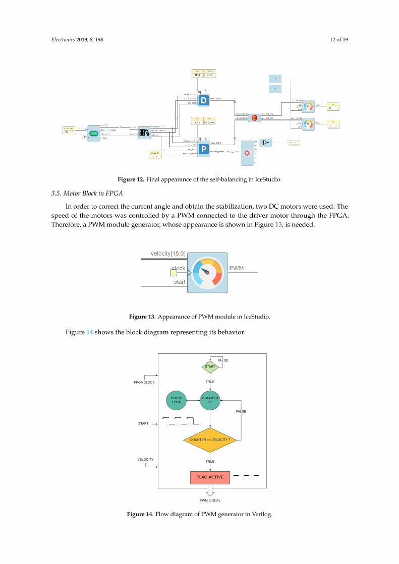