Experimental assessment of vertical shear force and bending ...
Upload
khangminh22Category
view
1download
0
technologies
Article
A Self-Deformation Robot Design IncorporatingBending-Type Pneumatic Artificial Muscles
Hiroki Tomori 1,* , Kenta Hiyoshi 1, Shonosuke Kimura 1, Naoya Ishiguri 2 and Taisei Iwata 2
1 Department of Mechanical Systems Engineering, Graduate School of Science and Engineering,Yamagata University, Yamagata 992-8510, Japan
2 Department of Mechanical Systems Engineering, Faculty of Engineering, Yamagata University,Yamagata 992-8510, Japan
* Correspondence: [email protected]; Tel.: +81-238-26-3217
Received: 21 June 2019; Accepted: 19 July 2019; Published: 23 July 2019�����������������
Abstract: With robots becoming closer to humans in recent years, human-friendly robots made ofsoft materials provide a new line of research interests. We designed and developed a soft robotthat can move via self-deformation toward the practical application of monitoring children and theelderly on a daily basis. The robot’s structure was built out of flexible frames, which are bending-typepneumatic artificial muscles (BPAMs). We first provide a description and discussion on the nature ofBPAM, followed by static characteristics experiment. Although the BPAM theoretical model shares asimilar tendency with the experimental results, the actual BPAMs moved along the depth direction.We then proposed and demonstrated an effective locomotion method for the robot and calculated itslocomotion speed by measuring its drive time and movement distance. Our results confirmed thereasonability of the robot’s speed for monitoring children and the elderly. Nevertheless, during thedemonstration, some BPAMs were bent sharply by other activated BPAMs as the robot was driving,leaving a little damage on these BPAMs. This will be addressed in our future work.
Keywords: pneumatic; artificial muscle; soft robot
1. Introduction
Conventional robots are typically industrial robots with a separate workspace from humanworkers. This way, the robots could increase their own stiffness, improve their work accuracy, andbecome faster in completing their tasks. By contrast, robots developed recently have become closerto humans. Because such types are often in contact with humans, they should be designed to securehigh safety for humans and the surroundings. Nevertheless, unlike industrial robots, human-friendlyrobots assume a complicated life space. For instance, they are installed with sensors for depth, force,and torque to help them avoid collisions with obstacles or reduce the damage dealt [1,2]. However,technologies for robot recognition of a complicated environment have high calculation costs and maynot prevent all unintended collisions. Therefore, these robots need constructive safety, i.e., they needto protect themselves in case of collision with humans or the environment.
Soft robotics is currently an attractive research interest highlighting this need. Soft robots tendto be lightweight and flexible, which is ideal for constructive safety [3]. Suzumori developed anarm consisting of an air balloon to achieve height safety [4]. Ansari developed a manipulator usingMcKibben actuators for the personal care of elder people [5]. Ward-Cherrier developed a soft tactilesensor that allows a robot to interact with humans safely [6]. Furthermore, these characteristics of asoft robot also improves performance. Ortiz [7] suggested that a robot’s bioinspired motion improveslocomotion performance on ground-like granular substrates. Especially, to achieve the bioinspiredmotion, they developed soft robot digging through dry granular ground. Furthermore, Suzumori [8]
Technologies 2019, 7, 51; doi:10.3390/technologies7030051 www.mdpi.com/journal/technologies

Technologies 2019, 7, 51 2 of 12
developed a pipe inspection robot using flexible microactuators, which can adapt to a narrow andcomplex space without complicated control. Hawkes developed a soft robot that can navigate in anarrow space by growing [9]. Such a behavior is possible because these robots have a soft construction.In addition, soft skins that contribute to robots increasing environment adaptability [10] and graspingability [11] were developed. In this manner, soft robots have advantages in terms of not only safety forhuman and the surrounding environment, but also in terms of performance such as the adaptabilitytoward complicated and indeterminate environments, and in reducing calculation costs in controland the grasping ability of the manipulator. As such, research about soft sensors [12] will acceleratethe development of soft robots. We also consider that flexible touch and motion reduce the chanceof an intimidating impression to the user. Thus, we aim to develop a soft-material, human-friendlyrobot incorporating these features and expect it to be applied for the daily monitoring of people,especially children and the elderly. This robot needs to have high safety and adaptability to a human’slife environment.
Configuration-wise, these robots are normally driven by soft actuators made of soft materials suchas rubber, gel, or a polymer [13,14]. Though flexible actuators tend to be less powerful, accurate, andresponsive than high-stiffness actuators, their flexibility offers advantages in terms of environmentaladaptability. Commonly used soft actuators include ionic polymer-metal composites (IPMC) [15,16],dielectric elastomer actuators (DEA) [16], conducting polymer [17], shape memory actuator (SMA) [18],etc. Although they have characteristics as a soft actuator, there are various advantage and disadvantages.Kongahage [19] had compared characteristics between soft actuators. In general, the strain toleranceof these actuators is low as a whole, yet a soft robot needs a practical output and strain in order towork. Among them, SMA, DE, and a pneumatic actuator can possibly to satisfy the requirements.Additionally, considering that SMA and DE need heating and high voltage, respectively, we concludedthat a pneumatic actuator is suitable for a daily monitoring robot. A pneumatic actuator consists offibers and a flexible membrane like rubber. It actuates via deformation (expansion and contraction),similar to muscles, upon the application of air pressure. The actuator has no sliding or movingparts, such as a pneumatic cylinder [20], which means some advantages such as dust proofing, highsealability, and low noise. Also, its working fluid (air) is environment- and user-friendly. Furthermore,the pneumatic actuator’s flexibility and lightness can be used for a highly human-friendly actuatorwhile it generates a high output relative to other soft actuators. Thus, its high safety encourages theapplication of robots toward working nearby humans, for example, in the rehabilitation field [21,22].
Besides using pneumatic rubber actuators, we designed a simple structure and shape of thesoft robot to make it sturdy but lightweight, and to especially focus on its flexibility. This is adifferent scheme from previous pneumatic-rubber-actuator-based typical robots that incorporate a rigidmechanism to transfer the actuator’s output into a link. For example, the wire-and-pulley mechanismcan translate the contraction of a pneumatic rubber artificial muscle to the pulley rotation [23,24],but can show flexibility only in the rotation direction of the pulley. We addressed this problem withthe proposed self-deformation robot (SDR) with an integrated soft frame mechanism. The robot isconstructed from pneumatic rubber actuators as soft frames and moves by deforming itself. We alsodeveloped a bending-type pneumatic rubber artificial muscle (BPAM) for frames. A BPAM is a rubbertube constrained by fibers that bends with the application of air pressure. Its basic principle is the sameas that described by Miyagawa [25]; in this reference, Miyagawa presented a tube-shape pneumaticsoft actuator that creates a bending motion. Then, they also investigated static characteristics of thatactuator using the principle of virtual work. Although the cross-section shape of their actuator differsfrom our BPAM, the procedure for the derivation of an equation model was applicable. This actuatordoes not impair the flexibility of the SDR because it can produce a bending motion without anyrigid mechanism.
We first explain the principle of BPAM and discuss the proposed SDR design. Afterward, weexperimentally demonstrate the SDR locomotion. We present the general findings of this study in thelast section.

Technologies 2019, 7, 51 3 of 12
2. Bending-Type Pneumatic Rubber Artificial Muscle
2.1. Mechanism of the BPAM
Photographs of the BPAM are displayed in Figure 1. This actuator consists of a rubber tube andan aramid fiber, and bends by applying air pressure. Here, the drive principle of BPAM is explainedwith Figure 2. In Figure 2, a rubber tube (A) expands in all directions (B) with air pressure by Pascal’sprinciple. Therefore, the aramid fiber rolled in the rubber tube without space restraints expands in aradial direction (C). In this case, the tube extends in only the axial direction by applying air pressure(D). In addition, an aramid fiber of 8 mm width was utilized to limit the axial length of a part of thetube walls (E). Due to this mechanism, the difference of extension in the tube upon the application ofair pressure produces bending of the BPAM in the direction where the axial length is constrained (F).
Technologies 2019, 7, x 3 of 12
2. Bending-Type Pneumatic Rubber Artificial Muscle
2.1. Mechanism of the BPAM
Photographs of the BPAM are displayed in Figure 1. This actuator consists of a rubber tube and
an aramid fiber, and bends by applying air pressure. Here, the drive principle of BPAM is explained
with Figure 2. In Figure 2, a rubber tube (A) expands in all directions (B) with air pressure by Pascal’s
principle. Therefore, the aramid fiber rolled in the rubber tube without space restraints expands in a
radial direction (C). In this case, the tube extends in only the axial direction by applying air pressure
(D). In addition, an aramid fiber of 8 mm width was utilized to limit the axial length of a part of the
tube walls (E). Due to this mechanism, the difference of extension in the tube upon the application of
air pressure produces bending of the BPAM in the direction where the axial length is constrained (F).
Then, a schematic of the BPAM is shown in Figure 3 and the specifications of the BPAM are
listed in Table 1. In Figure 3, we assumed the BPAM bends in the plane and load F was applied to
BPAM’s end orthogonally, as indicated by the red vector.
(a) (b)
Figure 1. A bending-type pneumatic artificial muscle: (a) air is released, and (b) air is applied.
Figure 2. Mechanism of BPAM.
Air pressure
Rubber tubearamid fiber (longitudinal direction)
terminal part
aramid fiber(circumferential direction)
(A)
(B)
(C)
(D)
(E)
Air pressure
Air pressure(F)
Extend
Restrained
Figure 1. A bending-type pneumatic artificial muscle: (a) air is released, and (b) air is applied.
Technologies 2019, 7, x 3 of 12
2. Bending-Type Pneumatic Rubber Artificial Muscle
2.1. Mechanism of the BPAM
Photographs of the BPAM are displayed in Figure 1. This actuator consists of a rubber tube and
an aramid fiber, and bends by applying air pressure. Here, the drive principle of BPAM is explained
with Figure 2. In Figure 2, a rubber tube (A) expands in all directions (B) with air pressure by Pascal’s
principle. Therefore, the aramid fiber rolled in the rubber tube without space restraints expands in a
radial direction (C). In this case, the tube extends in only the axial direction by applying air pressure
(D). In addition, an aramid fiber of 8 mm width was utilized to limit the axial length of a part of the
tube walls (E). Due to this mechanism, the difference of extension in the tube upon the application of
air pressure produces bending of the BPAM in the direction where the axial length is constrained (F).
Then, a schematic of the BPAM is shown in Figure 3 and the specifications of the BPAM are
listed in Table 1. In Figure 3, we assumed the BPAM bends in the plane and load F was applied to
BPAM’s end orthogonally, as indicated by the red vector.
(a) (b)
Figure 1. A bending-type pneumatic artificial muscle: (a) air is released, and (b) air is applied.
Figure 2. Mechanism of BPAM.
Air pressure
Rubber tubearamid fiber (longitudinal direction)
terminal part
aramid fiber(circumferential direction)
(A)
(B)
(C)
(D)
(E)
Air pressure
Air pressure(F)
Extend
Restrained
Figure 2. Mechanism of bending-type pneumatic artificial muscles (BPAM).
Then, a schematic of the BPAM is shown in Figure 3 and the specifications of the BPAM are listedin Table 1. In Figure 3, we assumed the BPAM bends in the plane and load F was applied to BPAM’send orthogonally, as indicated by the red vector.

Technologies 2019, 7, 51 4 of 12Technologies 2019, 7, x 4 of 12
Figure 3. Definition of dimension of BPAM.
Table 1. BPAM specifications.
Parameter Specification
Length (mm) 100
Outer diameter (mm) 21
Inner diameter (mm) 16
Weight (kg) 0.05
2.2. Static Characteristics Model of BPAM
Here, we provide an explanation of the static characteristics of the BPAM. In this section, we
obtained equation models based on the principle of virtual work with reference to Miyagawa’s
work [25]. An equilibrium between applied air pressure P (Pa), load F (N), and bending angle θ° is
illustrated via equations. It is used not only for understanding BPAM’s characteristics, but also for
force control and simulation as a future step.
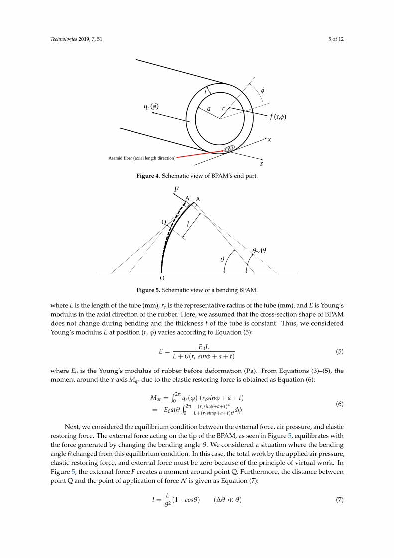
Figure 4 shows a view of BPAM’s end part. Furthermore, Figure 5 shows a schematic view of a
bending BPAM. In Figure 4, the force F(r, ϕ) acting on a small area dS at position (r, ϕ) of the surface
of the terminal part by air pressure, along with a moment around the x-axis Mf, are provided in
Equations (1) and (2):
𝐹(𝑟, 𝜙) = 𝑃𝑑𝑆 (1)
𝑀𝑓 = ∫𝐹(𝑟, 𝜙)(𝑟 𝑠𝑖𝑛𝜙 + 𝑡)𝑑𝑆𝑆
= 𝑃𝜋(𝑎3 + 𝑎2𝑡)
(2)
where α is the inner radius of the tube (mm) and t is the thickness of the tube (mm).
Then, we obtained a moment around the x-axis using the elastic restoring force of rubber. The
elastic restoring force qr(ϕ) acting at position ϕ on a cross-section surface of rubber tube is shown in
Equation (3):
𝑞𝑟(𝜙) = −𝐸𝑎𝑡
𝐿𝜃(𝑟𝑐 𝑠𝑖𝑛𝜙 + 𝑡)𝑑𝜙 (3)
2
tarc +=
(4)
L
D
Fθ
Air pressure
Rubber tube and aramid fiber (circumferential direction)
aramid fiber (longitudinal direction)
terminal part
Figure 3. Definition of dimension of BPAM.
Table 1. Bending-type pneumatic artificial muscles (BPAM) specifications.
Parameter Specification
Length (mm) 100Outer diameter (mm) 21Inner diameter (mm) 16
Weight (kg) 0.05
2.2. Static Characteristics Model of BPAM
Here, we provide an explanation of the static characteristics of the BPAM. In this section, weobtained equation models based on the principle of virtual work with reference to Miyagawa’swork [25]. An equilibrium between applied air pressure P (Pa), load F (N), and bending angle θ◦ isillustrated via equations. It is used not only for understanding BPAM’s characteristics, but also forforce control and simulation as a future step.
Figure 4 shows a view of BPAM’s end part. Furthermore, Figure 5 shows a schematic view of abending BPAM. In Figure 4, the force F(r, φ) acting on a small area dS at position (r, φ) of the surface ofthe terminal part by air pressure, along with a moment around the x-axis Mf, are provided in Equations(1) and (2):
F(r, φ) = PdS (1)
M f =∫
S F(r,φ)(r sinφ+ t)dS= Pπ
(a3 + a2t
) (2)
where α is the inner radius of the tube (mm) and t is the thickness of the tube (mm).Then, we obtained a moment around the x-axis using the elastic restoring force of rubber. The
elastic restoring force qr(φ) acting at position φ on a cross-section surface of rubber tube is shown inEquation (3):
qr(φ) = −EatLθ(rc sinφ+ t)dφ (3)
rc = a +t2
(4)
Technologies 2019, 7, 51 5 of 12
Technologies 2019, 7, x 6 of 12
Figure 4. Schematic view of BPAM’s end part.
Figure 5. Schematic view of a bending BPAM.
2.3. Static Characteristics Experiments
We conducted a static characteristics experiment to determine the fundamental characteristics
of the BPAM. The schematic for obtaining the relationships between air pressure, load, and bending
angle is depicted in Figure 6. Bending angle was measured using image analysis with motion capture
systems. In this experiment, air pressure was applied to the BPAM starting from a 0.02 baseline and
increased in increments of 0.02 MPa, whereas load Fl was increased in increments of 0.1 kg for a range
of 0–0.5 kg. Load F was calculated as the horizontal component of Fl.
The experimental results and theoretical lines are shown in Figure 7. Furthermore, Table 2 shows
the mean square error (MSE) between the experimental results and the theoretical line at each
pressure. From Figure 7, though the static characteristics model shared a similar tendency with the
experimental results, errors increased in the high- and low-pressure domain. This is also confirmed
in Table 2. We considered that this was because of the dead-band characteristic of BPAM at low
pressure and irregular bending at high pressure. Although the BPAM was regarded as bending in
plane, as shown in Figure 6, the actual BPAM moved along the depth direction as it was not
constrained by any rigid structure when the BPAM bent through a large angle due to high pressure.
Moreover, the BPAM developed manually by hand may twist because of the crooked arrangement
of the aramid fibers, which were aligned in the longitudinal direction. This theoretical model will be
used for simulation and force control of the SDR in future works. To improve the usability of the
model, it was necessary to include dead-band characteristics and the operable range into the model.
qr (ϕ)
f (r,ϕ)
t
a r
ϕ
z
x
Aramid fiber (axial length direction)
F
l
θ
θ-Δθ
AA'
Q
O
Figure 4. Schematic view of BPAM’s end part.
Technologies 2019, 7, x 6 of 12
Figure 4. Schematic view of BPAM’s end part.
Figure 5. Schematic view of a bending BPAM.
2.3. Static Characteristics Experiments
We conducted a static characteristics experiment to determine the fundamental characteristics
of the BPAM. The schematic for obtaining the relationships between air pressure, load, and bending
angle is depicted in Figure 6. Bending angle was measured using image analysis with motion capture
systems. In this experiment, air pressure was applied to the BPAM starting from a 0.02 baseline and
increased in increments of 0.02 MPa, whereas load Fl was increased in increments of 0.1 kg for a range
of 0–0.5 kg. Load F was calculated as the horizontal component of Fl.
The experimental results and theoretical lines are shown in Figure 7. Furthermore, Table 2 shows
the mean square error (MSE) between the experimental results and the theoretical line at each
pressure. From Figure 7, though the static characteristics model shared a similar tendency with the
experimental results, errors increased in the high- and low-pressure domain. This is also confirmed
in Table 2. We considered that this was because of the dead-band characteristic of BPAM at low
pressure and irregular bending at high pressure. Although the BPAM was regarded as bending in
plane, as shown in Figure 6, the actual BPAM moved along the depth direction as it was not
constrained by any rigid structure when the BPAM bent through a large angle due to high pressure.
Moreover, the BPAM developed manually by hand may twist because of the crooked arrangement
of the aramid fibers, which were aligned in the longitudinal direction. This theoretical model will be
used for simulation and force control of the SDR in future works. To improve the usability of the
model, it was necessary to include dead-band characteristics and the operable range into the model.
qr (ϕ)
f (r,ϕ)
t
a r
ϕ
z
x
Aramid fiber (axial length direction)
F
l
θ
θ-Δθ
AA'
Q
O
Figure 5. Schematic view of a bending BPAM.
where L is the length of the tube (mm), rc is the representative radius of the tube (mm), and E is Young’smodulus in the axial direction of the rubber. Here, we assumed that the cross-section shape of BPAMdoes not change during bending and the thickness t of the tube is constant. Thus, we consideredYoung’s modulus E at position (r, φ) varies according to Equation (5):
E =E0L
L + θ(rc sinφ+ a + t)(5)
where E0 is the Young’s modulus of rubber before deformation (Pa). From Equations (3)–(5), themoment around the x-axis Mqr due to the elastic restoring force is obtained as Equation (6):
Mqr =∫ 2π
0 qr(φ) (rcsinφ+ a + t)
= −E0atθ∫ 2π
0(rcsinφ+a+t)2
L+(rcsinφ+a+t)θdφ(6)
Next, we considered the equilibrium condition between the external force, air pressure, and elasticrestoring force. The external force acting on the tip of the BPAM, as seen in Figure 5, equilibrates withthe force generated by changing the bending angle θ. We considered a situation where the bendingangle θ changed from this equilibrium condition. In this case, the total work by the applied air pressure,elastic restoring force, and external force must be zero because of the principle of virtual work. InFigure 5, the external force F creates a moment around point Q. Furthermore, the distance betweenpoint Q and the point of application of force A’ is given as Equation (7):
l =Lθ2
(1− cosθ) (∆θ� θ) (7)

Technologies 2019, 7, 51 6 of 12
Additionally, work Wf by the moment from external force F is obtained as Equation (8):
W f = −Fl∆θ = −FLθ2
(1− cosθ)∆θ (8)
On the other hand, work Wc done by moment Mf and Mqr is shown in Equation (9):
Wc =(M f + Mqr
)∆θ (9)
Finally, the total work must be zero, as in Equation (10), because of the principle of virtual work.From this equation, the relationship between applied air pressure P, load F, and bending angle θ isillustrated as Equation (11):
−F Lθ2 (1− cosθ)∆θ+
(M f + Mqr
)∆θ = 0
F =M f +MqrLθ2 (1−cosθ)
(10)
P =F Lθ2 (1− cosθ) −Mqr
a3π+ a2tπ(11)
2.3. Static Characteristics Experiments
We conducted a static characteristics experiment to determine the fundamental characteristicsof the BPAM. The schematic for obtaining the relationships between air pressure, load, and bendingangle is depicted in Figure 6. Bending angle was measured using image analysis with motion capturesystems. In this experiment, air pressure was applied to the BPAM starting from a 0.02 baseline andincreased in increments of 0.02 MPa, whereas load Fl was increased in increments of 0.1 kg for a rangeof 0–0.5 kg. Load F was calculated as the horizontal component of Fl.Technologies 2019, 7, x 7 of 12
Figure 6. Schematic of the static characteristics experiment for BPAM.
Figure 7. Results of the static characteristics experiment and theoretical lines from a BPAM model.
Table 2. MSE of the static characteristics experiment results and theoretical lines.
Air Pressure (MPa) MSE Air Pressure (MPa) MSE
0.02 56.87 0.14 2.17
0.04 34.23 0.16 15.39
0.06 22.33 0.18 115.61
0.08 14.77 0.20 202.07
0.10 11.77 0.22 1316.83
0.12 9.13
3. Self-Deformation Robot (SDR)
3.1. Robot Design
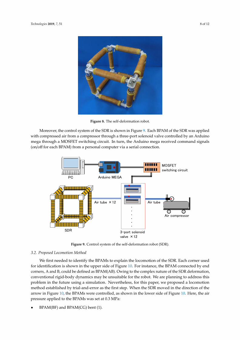
The SDR with BPAMs as flexible frames is displayed in Figure 8. Its structure was identical to a
wire frame and assumed a cubical shape as the SDR developed for the initial test. The cubic SDR had
a side 200-mm long and weighed 0.7 kg. The BPAMs were arranged as edges and were all connected
to each corner. Designed with an omnidirectional structure, aramid fibers limiting the axial length of
Load
Fl
PAir pressure
Load
θ
Bending angle
F
0
20
40
60
80
100
120
140
0 1 2 3 4 5 6 7 8 9
Ben
din
g a
ng
le θ
[deg
]
Load F [N]
0.02 MPa 0.04 MPa 0.06 MPa
0.08 MPa 0.1 MPa 0.12 MPa
0.14 MPa 0.16 MPa 0.18 MPa
0.2 MPa 0.22 MPa 0.02 MPa
0.04 MPa 0.06 MPa 0.08 MPa
0.1 MPa 0.12 MPa 0.14 MPa
0.16 MPa 0.18 MPa 0.2 MPa
0.22 MPa
Figure 6. Schematic of the static characteristics experiment for BPAM.
The experimental results and theoretical lines are shown in Figure 7. Furthermore, Table 2 showsthe mean square error (MSE) between the experimental results and the theoretical line at each pressure.From Figure 7, though the static characteristics model shared a similar tendency with the experimentalresults, errors increased in the high- and low-pressure domain. This is also confirmed in Table 2. Weconsidered that this was because of the dead-band characteristic of BPAM at low pressure and irregular

Technologies 2019, 7, 51 7 of 12
bending at high pressure. Although the BPAM was regarded as bending in plane, as shown in Figure 6,the actual BPAM moved along the depth direction as it was not constrained by any rigid structurewhen the BPAM bent through a large angle due to high pressure. Moreover, the BPAM developedmanually by hand may twist because of the crooked arrangement of the aramid fibers, which werealigned in the longitudinal direction. This theoretical model will be used for simulation and forcecontrol of the SDR in future works. To improve the usability of the model, it was necessary to includedead-band characteristics and the operable range into the model.
Technologies 2019, 7, x 7 of 12
Figure 6. Schematic of the static characteristics experiment for BPAM.
Figure 7. Results of the static characteristics experiment and theoretical lines from a BPAM model.
Table 2. MSE of the static characteristics experiment results and theoretical lines.
Air Pressure (MPa) MSE Air Pressure (MPa) MSE
0.02 56.87 0.14 2.17
0.04 34.23 0.16 15.39
0.06 22.33 0.18 115.61
0.08 14.77 0.20 202.07
0.10 11.77 0.22 1316.83
0.12 9.13
3. Self-Deformation Robot (SDR)
3.1. Robot Design
The SDR with BPAMs as flexible frames is displayed in Figure 8. Its structure was identical to a
wire frame and assumed a cubical shape as the SDR developed for the initial test. The cubic SDR had
a side 200-mm long and weighed 0.7 kg. The BPAMs were arranged as edges and were all connected
to each corner. Designed with an omnidirectional structure, aramid fibers limiting the axial length of
Load
Fl
PAir pressure
Load
θ
Bending angle
F
0
20
40
60
80
100
120
140
0 1 2 3 4 5 6 7 8 9
Ben
din
g a
ng
le θ
[deg
]
Load F [N]
0.02 MPa 0.04 MPa 0.06 MPa
0.08 MPa 0.1 MPa 0.12 MPa
0.14 MPa 0.16 MPa 0.18 MPa
0.2 MPa 0.22 MPa 0.02 MPa
0.04 MPa 0.06 MPa 0.08 MPa
0.1 MPa 0.12 MPa 0.14 MPa
0.16 MPa 0.18 MPa 0.2 MPa
0.22 MPa
Figure 7. Results of the static characteristics experiment and theoretical lines from a BPAM model.
Table 2. MSE of the static characteristics experiment results and theoretical lines.
Air Pressure (Mpa) MSE Air Pressure (MPa) MSE
0.02 56.87 0.14 2.170.04 34.23 0.16 15.390.06 22.33 0.18 115.610.08 14.77 0.20 202.070.10 11.77 0.22 1316.830.12 9.13
3. Self-Deformation Robot (SDR)
3.1. Robot Design
The SDR with BPAMs as flexible frames is displayed in Figure 8. Its structure was identicalto a wire frame and assumed a cubical shape as the SDR developed for the initial test. The cubicSDR had a side 200-mm long and weighed 0.7 kg. The BPAMs were arranged as edges and wereall connected to each corner. Designed with an omnidirectional structure, aramid fibers limiting theaxial length of the BPAMs were facing the cube center, which allowed for SDR expansion towardthe outer side. Unactuated BPAMs were bent in various directions relative to the actuated BPAMs.Consequentially, the SDR could deform itself by bending, twisting, or getting flattened, a behaviorunique to soft-actuator-driven soft robots.
Technologies 2019, 7, 51 8 of 12
Technologies 2019, 7, x 8 of 12
the BPAMs were facing the cube center, which allowed for SDR expansion toward the outer side.
Unactuated BPAMs were bent in various directions relative to the actuated BPAMs. Consequentially,
the SDR could deform itself by bending, twisting, or getting flattened, a behavior unique to soft-
actuator-driven soft robots.
Moreover, the control system of the SDR is shown in Figure 9. Each BPAM of the SDR was
applied with compressed air from a compressor through a three-port solenoid valve controlled by an
Arduino mega through a MOSFET switching circuit. In turn, the Arduino mega received command
signals (on/off for each BPAM) from a personal computer via a serial connection.
Figure 8. The self-deformation robot.
Figure 9. Control system of the SDR.
3.2. Proposed Locomotion Method
We first needed to identify the BPAMs to explain the locomotion of the SDR. Each corner used
for identification is shown in the upper side of Figure 10. For instance, the BPAM connected by end
corners, A and B, could be defined as BPAM(AB). Owing to the complex nature of the SDR
deformation, conventional rigid-body dynamics may be unsuitable for the robot. We are planning to
address this problem in the future using a simulation. Nevertheless, for this paper, we proposed a
locomotion method established by trial-and-error as the first step. When the SDR moved in the
direction of the arrow in Figure 10, the BPAMs were controlled, as shown in the lower side of
Figure 10. Here, the air pressure applied to the BPAMs was set at 0.3 MPa:
Air compressor
PC Arduino MEGA
MOSFET switching circuit
3-port solenoid valve ×12
SDR
・・・・・・
Air tube ×12 Air tube
Figure 8. The self-deformation robot.
Moreover, the control system of the SDR is shown in Figure 9. Each BPAM of the SDR was appliedwith compressed air from a compressor through a three-port solenoid valve controlled by an Arduinomega through a MOSFET switching circuit. In turn, the Arduino mega received command signals(on/off for each BPAM) from a personal computer via a serial connection.
Technologies 2019, 7, x 8 of 12
the BPAMs were facing the cube center, which allowed for SDR expansion toward the outer side.
Unactuated BPAMs were bent in various directions relative to the actuated BPAMs. Consequentially,
the SDR could deform itself by bending, twisting, or getting flattened, a behavior unique to soft-
actuator-driven soft robots.
Moreover, the control system of the SDR is shown in Figure 9. Each BPAM of the SDR was
applied with compressed air from a compressor through a three-port solenoid valve controlled by an
Arduino mega through a MOSFET switching circuit. In turn, the Arduino mega received command
signals (on/off for each BPAM) from a personal computer via a serial connection.
Figure 8. The self-deformation robot.
Figure 9. Control system of the SDR.
3.2. Proposed Locomotion Method
We first needed to identify the BPAMs to explain the locomotion of the SDR. Each corner used
for identification is shown in the upper side of Figure 10. For instance, the BPAM connected by end
corners, A and B, could be defined as BPAM(AB). Owing to the complex nature of the SDR
deformation, conventional rigid-body dynamics may be unsuitable for the robot. We are planning to
address this problem in the future using a simulation. Nevertheless, for this paper, we proposed a
locomotion method established by trial-and-error as the first step. When the SDR moved in the
direction of the arrow in Figure 10, the BPAMs were controlled, as shown in the lower side of
Figure 10. Here, the air pressure applied to the BPAMs was set at 0.3 MPa:
Air compressor
PC Arduino MEGA
MOSFET switching circuit
3-port solenoid valve ×12
SDR
・・・・・・
Air tube ×12 Air tube
Figure 9. Control system of the self-deformation robot (SDR).
3.2. Proposed Locomotion Method
We first needed to identify the BPAMs to explain the locomotion of the SDR. Each corner usedfor identification is shown in the upper side of Figure 10. For instance, the BPAM connected by endcorners, A and B, could be defined as BPAM(AB). Owing to the complex nature of the SDR deformation,conventional rigid-body dynamics may be unsuitable for the robot. We are planning to address thisproblem in the future using a simulation. Nevertheless, for this paper, we proposed a locomotionmethod established by trial-and-error as the first step. When the SDR moved in the direction of thearrow in Figure 10, the BPAMs were controlled, as shown in the lower side of Figure 10. Here, the airpressure applied to the BPAMs was set at 0.3 MPa:
• BPAM(BF) and BPAM(CG) bent (1).

Technologies 2019, 7, 51 9 of 12
• BPAM(AB), BPAM(CD), BPAM(EF), and BPAM(GH) bent (2).• Air pressure in BPAM(BF) and BPAM(CG) was released; these BPAMs become unactuated (3).
Next, the SDR rolled (4).• Finally, air pressure in BPAM(AB), BPAM(CD), BPAM(EF), and BPAM(GH) was released.
Technologies 2019, 7, x 9 of 12
• BPAM(BF) and BPAM(CG) bent (1).
• BPAM(AB), BPAM(CD), BPAM(EF), and BPAM(GH) bent (2).
• Air pressure in BPAM(BF) and BPAM(CG) was released; these BPAMs become unactuated (3).
Next, the SDR rolled (4).
• Finally, air pressure in BPAM(AB), BPAM(CD), BPAM(EF), and BPAM(GH) was released.
Numbers from (1) to (4) in the above explanations correspondent to the sequence numbers in
Figure 10.
Using this procedure, the SDR rolled in such a way that the plane face of BCGF shifted to the
bottom. Step 1 was considered when the SDR’s center of gravity tilted toward the locomotion
direction, followed by Step 2, where it became unstable and rolled over to the direction along which
the center of gravity tilted in Step 1. As the SDR was an omnidirectional structure, it could continue
moving on the same manner.
Figure 10. Identification of BPAMs of the SDR, along with the locomotion sequence.
4. Locomotion Demonstration
Subsequently, we undertook a locomotion test for the SDR. The SDR locomotion cycle using a
locomotion approach explained in Section 3.2 of Chapter 3 is shown in Figure 11. Here, phases 1 to 2
correspond to Step 1 of the locomotion method, phases 2 to 3 for Step 2, phases 3 to 5 for Step 3, and
phases 5 to 6 for Step 4. It could be observed that the SDR achieved locomotion by deforming itself.
In particular, BPAM(AE) and BPAM(DH) were bent sharply by other activated BPAMs in phases 4
and 5. Although allowed based on the structure, such deformation left a little damage on the BPAMs.
As such, this sharp bending should be avoided as much as possible in view of the lifetime of the
BPAMs.
Locomotion directionA B
CD
E F
GH
Front view
Top view
A B
E F
CD
A B
A B
E F
A
B
E
F
CD
A B
CD
A B
A
B
E
F
AE
DH
(1) (2) (3) (4)
Inactive BPAM
Activated BPAM
Figure 10. Identification of BPAMs of the SDR, along with the locomotion sequence.
Numbers from (1) to (4) in the above explanations correspondent to the sequence numbers inFigure 10.
Using this procedure, the SDR rolled in such a way that the plane face of BCGF shifted to thebottom. Step 1 was considered when the SDR’s center of gravity tilted toward the locomotion direction,followed by Step 2, where it became unstable and rolled over to the direction along which the center ofgravity tilted in Step 1. As the SDR was an omnidirectional structure, it could continue moving on thesame manner.
4. Locomotion Demonstration
Subsequently, we undertook a locomotion test for the SDR. The SDR locomotion cycle using alocomotion approach explained in Section 3.2 of Chapter 3 is shown in Figure 11. Here, phases 1 to 2correspond to Step 1 of the locomotion method, phases 2 to 3 for Step 2, phases 3 to 5 for Step 3, andphases 5 to 6 for Step 4. It could be observed that the SDR achieved locomotion by deforming itself. Inparticular, BPAM(AE) and BPAM(DH) were bent sharply by other activated BPAMs in phases 4 and 5.Although allowed based on the structure, such deformation left a little damage on the BPAMs. Assuch, this sharp bending should be avoided as much as possible in view of the lifetime of the BPAMs.

Technologies 2019, 7, 51 10 of 12
Technologies 2019, 7, x 10 of 12
Figure 11. Locomotion of the SDR.
Accordingly, we conducted a simplified experiment to measure the locomotion speed of the SDR.
Here, we measured the time for each step and movement distance, as shown, respectively, in
Figure 12a,b for one locomotion cycle. Afterward, we calculated the locomotion speed from the time
and distance data. We conducted locomotion experiments 10 times. Then, the average time, distance,
and speed from them were calculated.
The movement distances were almost identical to the side length. Owing to the slips and bounds
in Step 3, the distances were often longer than 200 mm, and the step time varied. Moreover, although
there was variability in locomotion speed, the average speed was 20 mm/s, which is reasonable for
our application.
(a) (b)
Figure 12. Measurement results of locomotion speed.
5. Discussion
By conducting the locomotion demonstration seen in Chapter 4, we observed some interactions
between BPAMs in the SDR. While an activated BPAM bent an adjacent inactive BPAM (phases 2
and 4 in Figure 11), two activated BPAMs suppressed the bending of each other (phase 3 in
Figure 11). Each BPAM generated a bending moment that bent adjacent BPAMs inward when
activated. Since a BPAM activated with a high pressure resulted in a sharp flexure of other BPAMs,
we need to control the intensity of interactions. For example, the sharp flexure of an inactive BPAM
can be suppressed by applying air pressure to that BPAM. However, this method does not change
the intensity of interaction, and the whole stiffness of the SDR will increase due to activated BPAMs
bending each other antagonistically. On the other hand, a decreasing stiffness of corner parts can
decrease the intensity of interactions. Flexible corner parts absorb the bending moment from
0
2
4
6
8
10
12
14
16
Tim
e [s
]
Experiment number
Step 1 Step 2 Step 3 Step 4
0
5
10
15
20
25
30
190
200
210
220
230
240
250
Spee
d [
mm
/s]
Dis
tance
[m
m]
Experiment number
Distance[mm] Speed [mm/s]
Figure 11. Locomotion of the SDR.
Accordingly, we conducted a simplified experiment to measure the locomotion speed of theSDR. Here, we measured the time for each step and movement distance, as shown, respectively, inFigure 12a,b for one locomotion cycle. Afterward, we calculated the locomotion speed from the timeand distance data. We conducted locomotion experiments 10 times. Then, the average time, distance,and speed from them were calculated.
Technologies 2019, 7, x 10 of 12
Figure 11. Locomotion of the SDR.
Accordingly, we conducted a simplified experiment to measure the locomotion speed of the SDR.
Here, we measured the time for each step and movement distance, as shown, respectively, in
Figure 12a,b for one locomotion cycle. Afterward, we calculated the locomotion speed from the time
and distance data. We conducted locomotion experiments 10 times. Then, the average time, distance,
and speed from them were calculated.
The movement distances were almost identical to the side length. Owing to the slips and bounds
in Step 3, the distances were often longer than 200 mm, and the step time varied. Moreover, although
there was variability in locomotion speed, the average speed was 20 mm/s, which is reasonable for
our application.
(a) (b)
Figure 12. Measurement results of locomotion speed.
5. Discussion
By conducting the locomotion demonstration seen in Chapter 4, we observed some interactions
between BPAMs in the SDR. While an activated BPAM bent an adjacent inactive BPAM (phases 2
and 4 in Figure 11), two activated BPAMs suppressed the bending of each other (phase 3 in
Figure 11). Each BPAM generated a bending moment that bent adjacent BPAMs inward when
activated. Since a BPAM activated with a high pressure resulted in a sharp flexure of other BPAMs,
we need to control the intensity of interactions. For example, the sharp flexure of an inactive BPAM
can be suppressed by applying air pressure to that BPAM. However, this method does not change
the intensity of interaction, and the whole stiffness of the SDR will increase due to activated BPAMs
bending each other antagonistically. On the other hand, a decreasing stiffness of corner parts can
decrease the intensity of interactions. Flexible corner parts absorb the bending moment from
0
2
4
6
8
10
12
14
16
Tim
e [s
]
Experiment number
Step 1 Step 2 Step 3 Step 4
0
5
10
15
20
25
30
190
200
210
220
230
240
250
Spee
d [
mm
/s]
Dis
tance
[m
m]
Experiment number
Distance[mm] Speed [mm/s]
Figure 12. Measurement results of locomotion speed. (a) Time for each step; (b) Movement distanceand locomotion speed.
The movement distances were almost identical to the side length. Owing to the slips and boundsin Step 3, the distances were often longer than 200 mm, and the step time varied. Moreover, althoughthere was variability in locomotion speed, the average speed was 20 mm/s, which is reasonable forour application.
5. Discussion
By conducting the locomotion demonstration seen in Chapter 4, we observed some interactionsbetween BPAMs in the SDR. While an activated BPAM bent an adjacent inactive BPAM (phases 2 and4 in Figure 11), two activated BPAMs suppressed the bending of each other (phase 3 in Figure 11).Each BPAM generated a bending moment that bent adjacent BPAMs inward when activated. Since aBPAM activated with a high pressure resulted in a sharp flexure of other BPAMs, we need to controlthe intensity of interactions. For example, the sharp flexure of an inactive BPAM can be suppressedby applying air pressure to that BPAM. However, this method does not change the intensity of

Technologies 2019, 7, 51 11 of 12
interaction, and the whole stiffness of the SDR will increase due to activated BPAMs bending each otherantagonistically. On the other hand, a decreasing stiffness of corner parts can decrease the intensityof interactions. Flexible corner parts absorb the bending moment from activated BPAMs and willprevent sharp flexure of adjacent inactive BPAMs. Although this method reduces the load of theSDR, interactions that have too low a pressure may result in a reduction of deformation of the SDR.Appropriate stiffness of each part of the SDR, and not just the corner parts, need to be decided upon forimproving performance. Due to the difficulty of applying rigid-body dynamics to the SDR, designingstiffness of the body using simulations is regarded as useful. An improved model of the BPAM willhelp us to develop the simulation.
6. Conclusions
For this paper, we developed an SDR using BPAMs. We provided a description and discussion forthe BPAMs and conducted a static characteristics experiment, in which the BPAM model exhibited asimilar tendency with the experimental results, and the actual BPAM particularly moved along thedirection of depth. Moreover, we proposed and demonstrated an effective method of locomotion forthe SDR. We calculated the locomotion speed by measuring the drive time and movement distance.For the primary objective of monitoring children and the elderly, the SDR’s speed was consideredreasonable. However, during the demonstration, some BPAMs were bent sharply by other activatedBPAMs during the SDR driving process, leaving a little deformation on these BPAMs.
In the future, we are planning to improve the BPAM structure to prevent sharp bending andunnecessary twists while the SDR is driving, along with the possibility to equip the SDR with built-incontrol systems, such as a compressor. Additionally, we are planning to mount sensors, including atactile sensor and an attitude sensor, and a camera on the SDR for practical use. We are also planningto optimize the SDR motion and body design via simulation. Then, we are also planning to usesimulations for locomotion planning. Improving the theoretical model, such as including operablerange into the model, is necessary to achieve it.
Author Contributions: Conceptualization, H.T. and K.H.; software, H.T.; validation, H.T. and N.I.; formal analysis,S.K.; investigation, N.I. and T.I.; writing—original draft preparation, H.T.; visualization, H.T.; supervision, H.T.;project administration, H.T.
Funding: This research was supported by the Program on Open Innovation Platform with Enterprises, ResearchInstitute and Academia (OPERA) from Japan Science and Technology Agency (JST) (grant no. JPMJOP1614).
Acknowledgments: The bending-type pneumatic artificial muscles used aramid fiber provided by Teijin Ltd., towhich we would like to express gratitude.
Conflicts of Interest: The authors declare no conflict of interest.
References
1. Ragaglia, M.; Zanchettin, A.M.; Rocco, P. Trajectory generation algorithm for safe human-robot collaborationbased on multiple depth sensor measurements. Mechatronics 2018, 55, 267–281. [CrossRef]
2. Sim, O.; Oh, J.; Lee, K.; Oh, J.H. Collision detection and safe reaction algorithm for non-backdrivablemanipulator with single force/torque sensor. J. Intell. Robot. Syst. 2018, 91, 403–412. [CrossRef]
3. Yang, H.; Xu, M.; Li, W.; Zhang, S. Design and Implementation of a soft robotic arm driven by SMA coils.IEEE Trans. Ind. Electron. 2019, 66, 6108–6116. [CrossRef]
4. Takeichi, M.; Suzumori, K.; Endo, G.; Nabae, H. Development of a 20-m-long giacometti arm with balloonbody based on kinematic model with air resistance. In Proceedings of the 2017 IEEE/RSJ InternationalConference on Intelligent Robots and Systems, Vancouver, BC, Canada, 24–28 September 2017; pp. 2710–2716.
5. Ansari, Y.; Manti, M.; Falotico, E.; Mollard, Y.; Cianchetti, M.; Laschi, C. Towards the development of a softmanipulator as an assistive robot for personal care of elderly people. Int. J. Adv. Robot. Syst. 2017, 14, 1–17.[CrossRef]

Technologies 2019, 7, 51 12 of 12
6. Ward-Cherrier, B.; Pestell, N.; Cramphorn, L.; Winstone, B.; Giannaccini, M.E.; Rossiter, J.; Lepora, N.F. TheTacTip Family: Soft Optical Tactile Sensors with 3D-Printed Biomimetic Morphologies. Soft Robot. 2018, 5,216–227. [CrossRef] [PubMed]
7. Ortiz, D.; Gravish, N.; Tolley, M.T. Soft Robot Actuation Strategies for Locomotion in Granular Substrates.IEEE Robot. Autom. Lett. 2019, 4, 2630–2636. [CrossRef]
8. Suzumori, K.; Abe, A. Applying flexible microactuators to pipeline inspection robots. In Proceedings of theIMACS/SICE International Symposium on Robotics, Mechatronics and Manufacturing Systems, Tempe, AZ,USA, 15–17 March 1993; pp. 515–520.
9. Hawkes, E.W.; Blumenschein, L.H.; Greer, J.D.; Okamura, A.M. A soft robot that navigates its environmentthrough growth. Sci. Robot. 2017, 2, eaan3028. [CrossRef]
10. Digumarti, K.M.; Conn, A.T.; Rossiter, J. Pellicular Morphing Surfaces for Soft Robots. IEEE Robot. Autom.Lett. 2019, 4, 2304–2309. [CrossRef]
11. Bolson, N.; Singh, D.; Lube, V.; Lubineau, G. All-polymer based polymorph skin with controllable surfacetexture. Smart Mater. Struct. 2019, 28, 075011. [CrossRef]
12. Thuruthel, T.G.; Shih, B.; Laschi, C.; Tolley, M.T. Soft robot perception using embedded soft sensors andrecurrent neural networks. Sci. Robot. 2019, 4, eaav1488. [CrossRef]
13. Shiblee, M.N.; Ahmed, K.; Kawakami, M.; Furukawa, H. 4D Printing of shape-memory hydrogels forsoft-robotic functions. Int. J. Adv. Mater. Technol. 2019, 4, 1900071. [CrossRef]
14. Akbari, S.; Sakhaei, A.H.; Panjwani, S.; Kowsari, K.; Serjourei, A.; Ge, Q. Multimaterial 3D printed softactuators powered by shape memory alloy wires. Sens. Actuators A Phys. 2019, 290, 177–189. [CrossRef]
15. Sung, W.Y.; Oh, I.K. A biomimetic jellyfish robot based on ionic polymer metal composite actuators. SmartMater. Struct. 2009, 18, 085002.
16. White, B.T.; Long, T.E. Advances in Polymeric Materials for Electromechanical Devices. Macromol. RapidCommun. 2019, 40, 1800521. [CrossRef] [PubMed]
17. Alici, G.; Devaud, V.; Renaud, P.; Spinks, G. Conducting polymer microactuators operating in air. J Micromech.Microeng. 2009, 19, 025017. [CrossRef]
18. Yan, S.Z.; Yang, T.F.; Liu, X.J.; Wang, R.C. Tactile feedback control for a gripper driven by SMA springs. AIPAdv. 2012, 2, 032134. [CrossRef]
19. Kongahage, D.; Foroughi, J. Actuator Materials: Review on Recent Advances and Future Outlook for SmartTextiles. Fibers 2019, 7, 21. [CrossRef]
20. Sarosi, J. Elimination of the hysteresis effect of pam actuator: Modelling and experimental studies. Tech. Gaz.2015, 22, 1489–1494.
21. Deaconescu, T.; Deaconescu, A. Pneumatic muscle actuated isokinetic equipment for the rehabilitationof patients with disabilities of the bearing joints. In Proceedings of the International MultiConference ofEngineers and Computer Scientists, Hong Kong, China, 18–20 March 2009; Volume 2, pp. 1823–1827.
22. Li, X.; Xia, H.; Guan, T. Development of legs rehabilitation exercise system driven by pneumatic muscleactuator. In Proceedings of the 2008 2nd International Conference on Bioinformatics and BiomedicalEngineering, Shanghai, China, 16–18 May 2008; pp. 1309–1311.
23. Zhao, L.; Liu, X.; Wang, T. Trajectory tracking control for double-joint manipulator systems driven bypneumatic artificial muscles based on a nonlinear extended state observer. Mech. Syst. Signal Process. 2019,122, 307–320. [CrossRef]
24. Tondu, B.; Ippolito, S.; Guiochet, J.; Daidie, A. A Seven-degree-of-freedom robot-arm driven by pneumaticartificial muscles for humanoid robots. Int. J. Robot. Res. 2005, 24, 257–274. [CrossRef]
25. Miyagawa, T.; Toya, K.; Kubota, Y. Static Characteristics of pneumatic soft actuator using fiber reinforcedrubber. In Proceedings of the 2007 JSME Conference on Robotics and Mechatronics, Akita, Japan, 10–12 May2007; pp. 1A2–A01. (In Japanese).
© 2019 by the authors. Licensee MDPI, Basel, Switzerland. This article is an open accessarticle distributed under the terms and conditions of the Creative Commons Attribution(CC BY) license (http://creativecommons.org/licenses/by/4.0/).
Copyright © 2022 FDOKUMEN


![05-03ChapGere[1] | Bending | Beam (Structure) - xdocs.net](https://static.fdokumen.com/doc/165x107/6323c1d9be5419ea700ebf89/05-03chapgere1-bending-beam-structure-xdocsnet.jpg)