Fabrication Guidelines for Cold Bending - CFSEI
23
Fabrication Guidelines for Cold Bending RESEARCH REPORT RP98-1 1998 Republished 2022 research report American Iron and Steel Institute
-
Upload
khangminh22 -
Category
Documents
-
view
1 -
download
0
Transcript of Fabrication Guidelines for Cold Bending - CFSEI
F a b r i c a t i o n G u i d e l i n e s f o r C o l d B e n d i n g R E S E A R C H R E P O R T R P 9 8 - 1 1 9 9 8 R e p u b l i s h e d 2 0 2 2
re
sear
ch re
port
American Iron and Steel Institute

Fabrication Guidelines for Cold Bending ii
DISCLAIMER
The material contained herein has been developed by researchers based on their research findings.
The material herein is for general information only. The information in it should not be used without first securing competent advice with respect to its suitability for any given application. The publication of the information is not intended as a representation or warranty on the part of the American Iron and Steel Institute, or of any other person named herein, that the information is suitable for any general or particular use or of freedom from infringement of any patent or patents. Anyone making use of the information assumes all liability arising from such use.
Copyright 1998 American Iron and Steel Institute Republished Edition Copyright 2022 American Iron and Steel Institute

Fabrication Guidelines for Cold Bending iii
PREFACE
To avoid cracking plates during cold bending, it is necessary to adopt a suitable minimum inside bend radius, which typically varies with plate thickness and grade. However, because of the addition of new plate grades over the years, it was suspected that current limits may not have been developed on a consistent basis. Therefore, the American Iron and Steel Institute (AISI) initiated a program to develop rational limits in 1998. This study was made to review information obtained in recent tests and develop suggested fabrication guidelines.

R. L. Brockenbrough & Associates, Inc. 17 Carleton Drive Pittsburgh, PA 15243
Fabrication Guidelines for Cold Bending
Prepared for the AISI Transportation and Infrastructure Committee, Washington, DC
June 29, 1998

1
Summary To avoid cracking plates during cold bending, it is necessary to adopt a suitable minimum inside bend radius, which typically varies with plate thickness and grade. However, because of the addition of new plate grades over the years, it was suspected that current limits may not have been developed on a consistent basis. Therefore, the American Iron and Steel Institute (AISI) initiated a program to develop rational limits. The present study was made to review information obtained in recent tests and develop suggested fabrication guidelines. The study described in Part I of this report showed that radius-to-thickness limits from idealized bending limit diagrams developed in recent tests can be used to establish fabrication limits if appropriate allowances are made for conditions in fabrication that differ from those in the tests. This includes adjustments to account for (1.) plate properties that approach minimum specified values rather than the typical properties of the test material, (2.) thicknesses greater than those tested, and (3.) edge or surface imperfections that may be present in typical fabrication. After making such adjustments, the following table of suggested limits was developed:
Suggested Minimum Inside Bend Radii for Cold Forming
Thickness (t), in.
Up to 3/4 Over 3/4 to 1, incl.
Over 1 to 2, incl.
Over 2 to 3, incl.
A36 1.5t 1.5t 1.5t 2.0t A572-50 1.5t 1.5t 2.0t 2.5t
A588 1.5t 1.5t 2.0t 2.5t A656-70 1.5t 1.5t - -
A514 1.75t 2.25t 4.5t 5.5t Note: Values are for bend lines perpendicular to direction of final rolling. If bend lines are parallel to final rolling direction, multiply values by 1.5. A comparison of the suggested values to fabrication guidelines of the American Institute of Steel Construction (AISC) showed that the suggested values are generally more liberal (allow tighter bends) than the AISC values. Thus, adoption of the suggested values would provide greater flexibility in fabrication in most cases. Based on this study, a table of suggested minimum inside radii for cold bending in typical fabrication was developed to include all structural grades listed in the bend test requirements (Table S1.1) of ASTM A6. The table, which is included in Part II of this report, should be considered as a basis for revising that specification.

2
Part I - Review of Tests and Development of Method Background In fabrication, plates are often bent to a radius in a press brake or die. Relatively thin plates may be roll formed to the desired profile. When conducted at room temperature, these processes are known collectively as "cold bending." To avoid cracking the plate during bending, it is necessary to adopt a suitable minimum inside bend radius, which typically varies with plate thickness and grade. However, because of the addition of new plate grades over the years, it was suspected that current limits may not have been developed on a consistent basis. Therefore, the American Iron and Steel Institute (AISI) initiated a program to develop rational limits for cold bending plates. First a test program was conducted on several steel grades as described below. Then the present study was made to review the information obtained and develop suggested fabrication guidelines for cold bending. Two sources may be referred to for cold bending limits. First, American Society for Testing and Materials (ASTM) Specification A6 [1]* includes a table giving bend diameter-to-thickness ratios for structural steel plate grades. This table is for material acceptance purposes; specimens generally 1-1/2 in. wide are bent to the specified diameter-to-thickness ratio to ensure that the material will not fracture under those conditions. The table is not intended for fabrication purposes. Second, manuals of the American Institute of Steel Construction (AISC) [2] give a table of recommended minimum radius-to-thickness ratios to be used in plate fabrication. The AISC limits are more conservative (greater bend radii) than the ASTM limits to allow for bending wider material and other conditions that may be present in fabrication. Tests by CTC Concurrent Technologies Corporation (CTC) conducted an experimental program, augmented by inelastic finite element analysis, to investigate the forming characteristics of five plate steels [3]. The investigation was sponsored by the American Iron and Steel Institute (AISI). The five steels investigated included ASTM A36, A572-50, A588, A656-70, and A514. Rectangular specimens were marked with a grid and cold bent in a forming die to a bend angle of 120°. If the specimen was not yet fractured it was then side pressed to fracture or to 180°. Strains were determined by measuring the grid spacing before and after testing, so that the maximum strain reached or the strain at fracture could be determined. The tests were initially conducted on plate ______________ * See References.

3
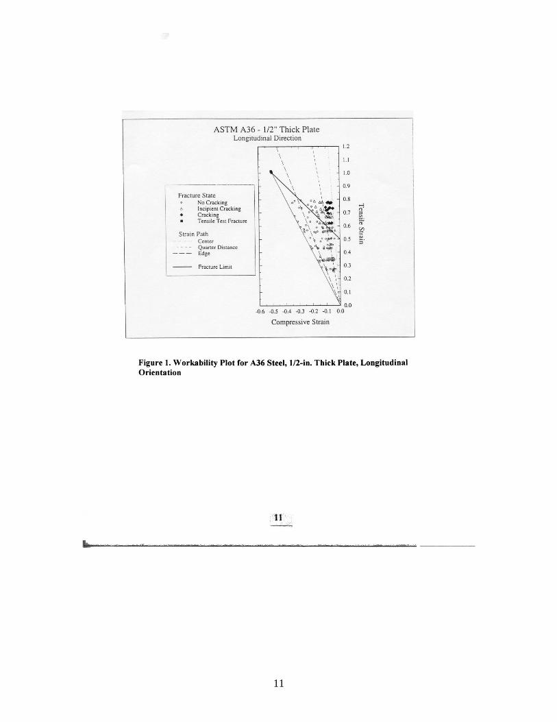
specimens 1/4, 3/8, and 1/2 in. thick, with bend line orientations both perpendicular and parallel to the rolling direction. Specimen width-to-thickness (w/t) ratios of 3:1, 5:1, and 10:1 were evaluated. All specimens had smooth edges to ensure that cracks did not emanate from the edges. Plots were made showing the strain states and cracking conditions observed. Figure 1 shows the data for 1/2-in. thick A36 steel longitudinal specimens (bend line perpendicular to the rolling direction). The results for thinner plates were generally similar. The top sloping line is a fracture limit that divides specimens that did not crack from those that cracked or showed incipient cracking. The strain state at the fracture limit corresponds to a particular bend angle and radius-to-thickness (R/t) ratio. Thus, a bending limit diagram could be constructed in terms of R/t and bend angle, with a line plotted to show combinations that were "safe" or "unsafe," that is, no-cracking or cracking conditions. Figure 2 shows such a diagram for A36 steel (bend line perpendicular to the rolling direction). Separate curves are shown for the three specimen w/t categories. Because the limit curves for w/t of 10:1 did not vary greatly from those for w/t of 5:1, it was assumed that the 10:1 results could be used for even wider plates with little error. Subsequently, cold bending tests were made on a group of 1-in. thick specimens of the five steels using a w/t of 10. Specimens were selected to represent safe and unsafe conditions, so that the results could be plotted to evaluate the bending limit diagrams. Figure 3 shows the results for A36 steel (bend line perpendicular to the rolling direction). These tests suggested that some modifications should be made to the bending limit diagrams to better match the results for the thicker material. Bending Limit Diagrams Further examination of the bending limit diagrams suggested that they could be idealized as rectangular diagrams as illustrated in Figure 4. According to such a diagram, any R/t ratio could be used up to a specific bending angle, θmax . For larger bend angles, the R/t must be greater than ( / )minR t to avoid cracking. Table 1 gives values of θmax and ( / )minR t for each steel and for both orientations.

4
Table 1
Forming Limits Based on Idealized Diagrams
Steel Orientation* θmax , deg. ( / )minR t A36 L
T 80 50
0.25 0.40
A572-50 L T
100 90
0.25 0.25
A588 L T
110 70
0.25 0.25
A656-70 L T
100 90
0.25 0.25
A514 L T
40 30
0.75 0.75
* L is for longitudinal specimen (bend line perpendicular to the rolling direction). T is for transverse specimen (bend line parallel to the rolling direction). Note: See Figure 4 for definitions. Some values of ( / )minR t listed here are more conservative than those recommended in Reference 3.
Method for Setting Fabrication Limits The idealized bending limit diagrams developed in this project can be used to establish fabrication limits if appropriate allowances are made for conditions in fabrication that differ from those in the tests. It is proposed that the fabrication limits for each steel be derived from the following relationship:
( ) ( )( ) 5.1/
// min321
≥
=
fab
fab
tRtRFFFtR
(1)
where: ( ) fabtR / = minimum radius-to-thickness ratio to be used in fabrication for cold bending to any angle ( )min/ tR = minimum radius-to-thickness ratio from idealized bending limit diagram based on tests F1 = Factor to adjust for minimum properties F2 = Factor to adjust for thickness F3 = Factor to adjust for imperfections

5
The ( )min/ tR for longitudinal specimens will be used to develop limits for bend lines perpendicular to the rolling direction. Limits for bend lines parallel to the rolling direction can be taken as 1.5 times the limits for perpendicular bend lines. The absolute lowest value of R/t = 1.5 is set as an arbitrary practical limit to avoid excessive strains. The adjustment factors for minimum properties, thickness, and imperfections are discussed in the following sections. Factor for Minimum Properties, F1 The CTC test specimens were taken from typical steel plate production. Thus, average material properties exceeded specification minimum values as detailed in Table 2. In a broad spectrum of fabrication operations, some material will likely approach specification minimum values, and a suitable allowance for this must be made. One measure of ability to deform is the percent elongation measured in a tensile test, particularly over a short gage length. Therefore, it is proposed to base the F1 factor for each steel on the ratio of the specified minimum percent elongation in 2 in. to that of the test material. Rounded values of F1 vary from 1.5 to 2.0, Table 3, and their use has the effect of increasing the minimum bend radius.
Table 2
Comparison of Specified and Test Average Tensile Properties
Steel
Spec.
or Test Avg.
Max.
Thick., in.
Min. Yield Stress,
ksi
Min. Tensile
Strength, ksi
% Elong.
in 2 in.
% Elong.
in 8 in.
A36 S - 36 58 23 20 T 44 65 34 25
A572-50 S 4 50 65 21 18 T 61 77 38 25
A588 S 4 50 70 21 18 S 5 46 67 21 - S 8 42 63 21 - T 59 78 46 23
A656-70 S 1 70 80 17 14 T 73 85 27 -
A514 S 2.5 100 110 18 - S 6 90 110 16 - T 106 115 26 -

6
Table 3
Factor for Minimum Properties, F1
Steel
Ratio of Test Average to Specified
Minimum % Elong. in 2 in.
F1 (Rounded Values)
A36 1.48 1.5 A572-50 1.81 2.0 A588 2.19 2.0 A656-70 1.59 2.0 A514 1.44 1.5
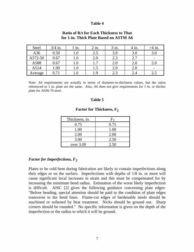
Factor for Thickness, F2 The initial CTC tests were conducted on material from 1/4 to 1/2 in. thick and thickness had little effect. Subsequent CTC tests on 1-in. thick material generally showed that somewhat larger R/t values should be used, and the idealized bending limit diagrams were adjusted to encompass 1in. plate. Thus, since the fabrication limits could be applied to material with a thickness of 8 in. or more, depending on grade, a suitable allowance for plate thickness must be made. As a guide for making this adjustment, the bend test requirements of ASTM A6 were examined. Although these requirements only apply to bend test specimens with smooth edges, the variation with thickness should be applicable here. The A6 requirements were normalized to the R/t limit for 1-in. thick plate and the results averaged for each thickness, Table 4. For individual grades, the normalized factor did not vary greatly from the average normalized factor for each thickness in most cases. Consequently, to adjust for thickness effects, these values have been rounded to the F2 values listed in Table 5. Application of these factors has the effect of increasing the minimum bend radius for plates over 1-in. thick and reducing it for 3/4-in. thick plate.
7
Table 4
Ratio of R/t for Each Thickness to That for 1-in. Thick Plate Based on ASTM A6
Steel 3/4 in. 1 in. 2 in. 3 in. 4 in. >4 in. A36 0.50 1.0 2.5 3.0 3.0 3.0
A572-50 0.67 1.0 2.0 2.3 2.7 - A588 0.67 1.0 1.7 2.0 2.0 2.0 A514 1.00 1.0 1.5 2.0 2.0 -
Average 0.71 1.0 1.9 2.3 2.4 2.5 Note: A6 requirements are actually in terms of diameter-to-thickness values, but the ratios referenced to 1 in. plate are the same. Also, A6 does not give requirements for 1 in. or thicker plate for A656-70 steel.
Table 5
Factor for Thickness, F2 Thickness, in. F2 0.75 0.75 1.00 1.00 2.00 2.00 3.00 2.50 over 3.00 2.50 Factor for Imperfections, F3 Plates to be cold bent during fabrication are likely to contain imperfections along their edges or on the surface. Imperfections with depths of 1/8 in. or more will cause significant local increases in strain and this must be compensated for by increasing the minimum bend radius. Estimation of the worst likely imperfection is difficult. AISC [2] gives the following guidance concerning plate edges: "Before bending, special attention should be paid to the condition of plate edges transverse to the bend lines. Flame-cut edges of hardenable steels should be machined or softened by heat treatment. Nicks should be ground out. Sharp corners should be rounded." No specific information is given on the depth of the imperfection or the radius to which it will be ground.

8
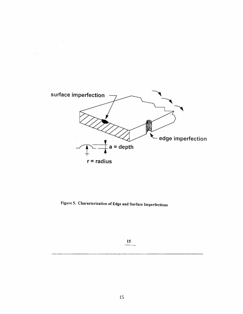
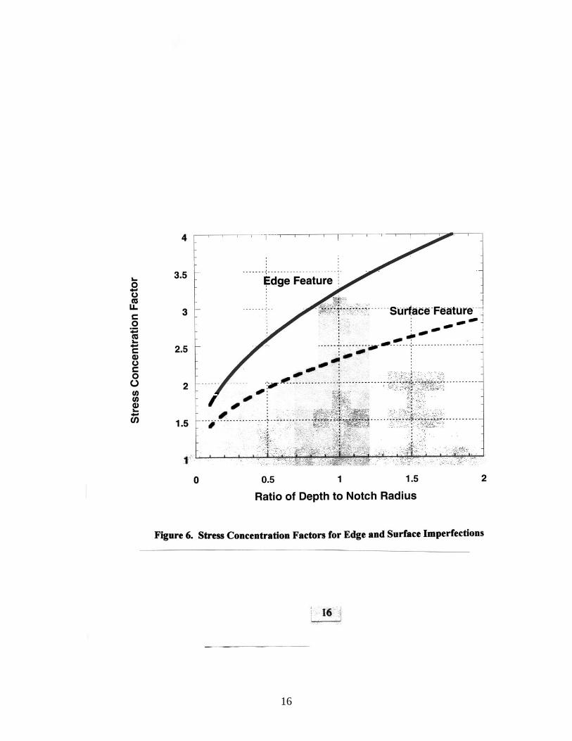
Figure 5 illustrates a section of a plate with the top surface stressed in tension during cold bending. It will be assumed that both the edge and the surface imperfection can be characterized by a shallow notch with depth "a" and radius "r". The stress concentration factors, assumed to be similar to the strain concentration factors, may be calculated from knowledge of the stress intensity factors [4], using the procedure described by Tada [5]. Figure 6 shows the calculated stress concentration factors for surface and edge features for a/r ratios of 2 or less. For purposes of estimating the reduction factor, an a/r ratio of 0.8 will be assumed for both surface and edge imperfections. In the case of an edge, this would be equivalent to a nick with a depth of 0.25 in., ground out leaving a radius of 5/16 in. In the case of a surface, this could be a similar ground-out nick or a smaller untouched rolling imperfection that could be represented by an a/r of 0.8. Referring to Figure 6, the factor for the edge condition would be 3.0 and that for the surface condition about 2.15. However, the strain limit diagrams developed in the CTC study [3] show that, because of the reduced constraint at the edges, the ratio of the tensile strain at fracture at the plate edge and at midwidth is about 3/2. Therefore, the factor for the edges can be taken as 2/3 x 3 or 2.0. Consequently, a reduction factor of F3 = 2 will be adopted to characterize typical edge and surface fabrication imperfections for all cases. Proposed Fabrication Limits Using Equation 1 and the adjustment factors discussed above, but disregarding the lower limit of 1.5, R/t limits for each steel and thickness category can be calculated as shown in Table 6. For example, the limit for 3-in. thick A36 steel plate is calculated as follows: F1 = 1.5 (Table 3) F2 = 2.5 (Table 5) F3 = 2.0 (applies to all) ( )min/ tR = 0.25 (Table 1) ( ) ( )min321 // tRFFFtR fab = = 1.5*2.5*2.0*0.25 = 1.88 Applying the lower limit of R/t = 1.5 and rounding a few values, the final set of suggested values is developed as shown in Table 7.
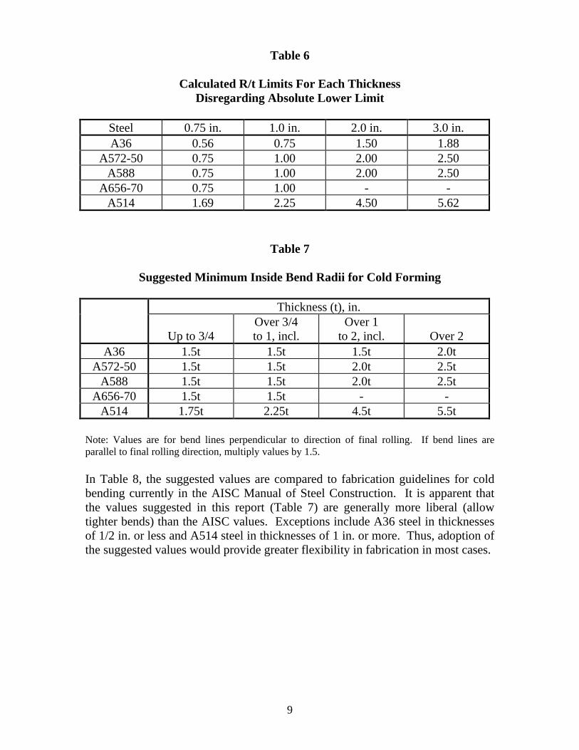
9
Table 6
Calculated R/t Limits For Each Thickness
Disregarding Absolute Lower Limit
Steel 0.75 in. 1.0 in. 2.0 in. 3.0 in. A36 0.56 0.75 1.50 1.88
A572-50 0.75 1.00 2.00 2.50 A588 0.75 1.00 2.00 2.50
A656-70 0.75 1.00 - - A514 1.69 2.25 4.50 5.62
Table 7
Suggested Minimum Inside Bend Radii for Cold Forming
Thickness (t), in.
Up to 3/4 Over 3/4 to 1, incl.
Over 1 to 2, incl.
Over 2
A36 1.5t 1.5t 1.5t 2.0t A572-50 1.5t 1.5t 2.0t 2.5t
A588 1.5t 1.5t 2.0t 2.5t A656-70 1.5t 1.5t - -
A514 1.75t 2.25t 4.5t 5.5t Note: Values are for bend lines perpendicular to direction of final rolling. If bend lines are parallel to final rolling direction, multiply values by 1.5. In Table 8, the suggested values are compared to fabrication guidelines for cold bending currently in the AISC Manual of Steel Construction. It is apparent that the values suggested in this report (Table 7) are generally more liberal (allow tighter bends) than the AISC values. Exceptions include A36 steel in thicknesses of 1/2 in. or less and A514 steel in thicknesses of 1 in. or more. Thus, adoption of the suggested values would provide greater flexibility in fabrication in most cases.

10
Table 8
Comparison to R/t Limits of AISC for Various Thicknesses
Steel
Limit
1/4 in.
1/2 in.
3/4 in.
1 in.
1-1/2 in.
2 in.
A36 AISC Present
1.5 1.5
1.5 1.5
- 1.5
2.0 1.5
3.0 1.75
4.0 2.0
A572-50 AISC Present
2.5 1.5
2.5 1.5
- 1.5
4.0 1.5
- 1.75
- 2.0
A588 AISC Present
2.0 1.5
3.0 1.5
- 1.5
5.0 1.5
- 1.75
- 2.0
A514 AISC Present
2.0 1.75
2.0 1.75
- 1.75
2.0 2.25
3.0 3.38
3.0 4.5
Note: AISC recommends hot forming for thicknesses greater than those shown. AISC does not include recommendations for A656-70 steel.
References 1. American Society for Testing and Materials, "Standard Specification A6 − General Requirements for Rolled Structural Steel Bars, Plates, Shapes, and Sheet Piling," Annual Book of ASTM Standards, Vol. 1.04, 1997. 2. American Institute of Steel Construction, Steel Construction Manual, Ninth Ed., 1989. 3. Holt, G. E., et al, "Minimum Cold Bend Radii Project − Final Report," Concurrent Technologies Corporation, January 27, 1997. 4. Murakami, Y., Ed., Stress Intensity Handbook, Vol. 2, Permagon Press, 1986. 5. Paris, P. C., Irwin, G. R., The Stress Analysis of Cracks Handbook, PP Inc., 1985.
11

12

13

14
15
16

17
Part II - Development of Guidelines for ASTM A6 Based on the study described in Part I, a set of guidelines was developed for the minimum cold bending radius suitable for typical fabrication, encompassing all steel plate specifications referenced in ASTM A6. To accomplish this, the steels were divided into six groups as shown in Table 9. The steels were arranged in Groups A through E according to their value of specified minimum elongation in 2 in., which was considered to be the dominant factor in distinguishing between different levels of formability. However, Group F was set up to include all steels with a ratio of specified minimum tensile strength to specified minimum yield strength of 1.15 or less. This was done because the tests described in Part I indicated that a greater bend radius was required for A514 steel, which has a tensile-yield ratio of 1.10. Table 10 shows the guidelines for cold bending for each group. Groups B through F each include at least one steel that was studied in Part I, and the minimum bend radii developed for that steel can be reasonably assumed to be applicable to the other steels in that group. Limited extrapolations were made where necessary based on engineering judgment and considering trends between grades in ASTM A6.

18
Table 9
Group Designations for Cold Bending
Group Designation
Range of Specified Minimum Elongation in 2 in., % (inclusive)
Steel Specifications and GradesB
A 30-26 A 283-A, A 283-B B 25-23 A 36, A 283-C, A 283-D, A 572-42, A 573-58, A 573-
65, A 656-60, A 633, A 709-36, A 945-50, A 945-65 C 22-21 A 242, A 529-50, A 529-55, A 572-50, A 573-70, A 588,
A 678-A, A 678-B, A 690, A 709-50, A 709-50W, A 808 D 20-19 A 572-55, A 656-60, A 678-C, A 678-D, A 709-70W,
A 709-HPS70W, A 852 E 18-17 A 572-60, A 572-65, A 656-70, A 871-60, A 871-65 FA - A514, A 656-80, A 709-100, A 709-100W, A 710
AGroup F includes all steels with a ratio of specified minimum tensile strength to specified minimum yield strength of 1.15 or less. BThe grade designation follows the dash; where no grade is shown, all grades and/or classes are included.
Table 10
Suggested Minimum Inside Radii for Cold BendingA
Thickness (t), in.
Group DesignationB
Up to 3/4
Over 3/4 to 1, incl.
Over 1 to 2, incl.
Over 2
A 1.5t 1.5t 1.5t 1.5t B 1.5t 1.5t 1.5t 2.0t C 1.5t 1.5t 2.0t 2.5t D 1.5t 1.5t 2.5t 3.0t E 1.5t 1.5t 3.0t 3.5t F 1.75t 2.25t 4.5t 5.5t
AValues are for bend lines perpendicular to direction of final rolling. If bend lines are parallel to final rolling direction, multiply values by 1.5. BSteels specifications included in the group designations may not include the entire thickness range shown in this table.

Res
earc
h R
epor
t R
P9
8-1
American Iron and Steel Institute
25 Massachusetts Avenue, NW Suite 800 Washington, DC 20001 www.steel.org