Fatigue Bending of V-Notched Cold-Sprayed FeCoCrNiMn ...
21
Citation: Cavaliere, P.; Perrone, A.; Silvello, A.; Laska, A.; Blasi, G.; Cano, I.G. Fatigue Bending of V-Notched Cold-Sprayed FeCoCrNiMn Coatings. Metals 2022, 12, 780. https://doi.org/10.3390/ met12050780 Academic Editors: Wei Zhou and Lan-Hong Dai Received: 30 March 2022 Accepted: 29 April 2022 Published: 30 April 2022 Publisher’s Note: MDPI stays neutral with regard to jurisdictional claims in published maps and institutional affil- iations. Copyright: © 2022 by the authors. Licensee MDPI, Basel, Switzerland. This article is an open access article distributed under the terms and conditions of the Creative Commons Attribution (CC BY) license (https:// creativecommons.org/licenses/by/ 4.0/). metals Article Fatigue Bending of V-Notched Cold-Sprayed FeCoCrNiMn Coatings Pasquale Cavaliere 1, * , Angelo Perrone 1 , Alessio Silvello 2 , Aleksandra Laska 1,3 , Gianni Blasi 1 and Irene G. Cano 2 1 Department of Innovation Engineering, University of Salento, Via per Arnesano, 73100 Lecce, Italy; [email protected] (A.P.); [email protected] (A.L.); [email protected] (G.B.) 2 Thermal Spray Center CPT, Universitat de Barcelona, 08007 Barcelona, Spain; [email protected] (A.S.); [email protected] (I.G.C.) 3 Faculty of Mechanical Engineering and Ship Technology, Gdansk University of Technology, Narutowicza 11/12, 80-233 Gdansk, Poland * Correspondence: [email protected] Abstract: Cold-spray coatings were produced by FeCoCrNiMn high-entropy alloy powders deposited on carbon steel substrate. The coatings were realized at intermediate temperature and high pressure (at 1100 ◦ C and 7 MPa). The coating microstructure was characterized by scanning electron microscopy and X-ray diffraction, revealing a very dense deposition and high flattening ratio of the splatted particles. This had a large influence on the strong adhesion of the coating to the substrate. The hardness and residual stress profiles were measured through nanoindentation and X-ray diffraction from the peak broadening measured layer by layer. The cyclic behavior of the coatings was evaluated through three- point bending tests performed on V-notched samples coated via cold spray. Cyclic tests were performed at different maximum strokes from 0.3 to 3.6 mm in order to monitor the crack initiation and propagation during bending tests. The fracture surface aspect was analyzed by scanning electron microscopy in order to reveal the fracture mechanisms in different deformation conditions. Keywords: high-entropy alloy; cold spray; residual stresses; V-notch; cyclic bending; fracture surface 1. Introduction High-entropy alloys (HEAs) exhibit new and interesting properties thanks to their particular crystal configuration due to the severe lattice distortion deriving from the well- known called cocktail effect [1–3]. High-entropy alloys are composed be a minimum of five metals in equiatomic or non-equiatomic configurations. The high entropy of the crystal configuration leads to exceptional mechanical properties in a very broad range of in-service temperatures [4,5]. Obviously, the main properties depend on the crystal structure be- longing to the single metal combination (FCC, BCC, FCC + BCC) [6]. It has been largely demonstrated that powder metallurgy processing routes can allow for a further increase in the mechanical properties of high-entropy alloys [7,8]. This is mainly due to the crystal modification at the nanoscale. Some scientific evidence has demonstrated how cold-spray coatings of high-entropy alloys powders show sound and high-strength protective lay- ers [9]. HEAs appear as an optimal solution for corrosion protection; many data belonging to various alloy configurations were described in [10]. Obviously, the corrosion resistance of these alloys strongly depends on the alloy configuration, on the crystal structure be- longing to the alloy composition, and on the processing route. Cold spray is well known for providing coatings for surface protection and/or repair. As a matter of fact, it has been demonstrated how compositionally complex alloys allow for an improvement in corrosion resistance [11]. It was also specified how the complexity of the alloy configuration is directly related to the increase in mechanical and physicochemical properties [12–14]. Metals 2022, 12, 780. https://doi.org/10.3390/met12050780 https://www.mdpi.com/journal/metals
-
Upload
khangminh22 -
Category
Documents
-
view
3 -
download
0
Transcript of Fatigue Bending of V-Notched Cold-Sprayed FeCoCrNiMn ...

Citation: Cavaliere, P.; Perrone, A.;
Silvello, A.; Laska, A.; Blasi, G.; Cano,
I.G. Fatigue Bending of V-Notched
Cold-Sprayed FeCoCrNiMn
Coatings. Metals 2022, 12, 780.
https://doi.org/10.3390/
met12050780
Academic Editors: Wei Zhou and
Lan-Hong Dai
Received: 30 March 2022
Accepted: 29 April 2022
Published: 30 April 2022
Publisher’s Note: MDPI stays neutral
with regard to jurisdictional claims in
published maps and institutional affil-
iations.
Copyright: © 2022 by the authors.
Licensee MDPI, Basel, Switzerland.
This article is an open access article
distributed under the terms and
conditions of the Creative Commons
Attribution (CC BY) license (https://
creativecommons.org/licenses/by/
4.0/).
metals
Article
Fatigue Bending of V-Notched Cold-SprayedFeCoCrNiMn CoatingsPasquale Cavaliere 1,* , Angelo Perrone 1 , Alessio Silvello 2 , Aleksandra Laska 1,3 , Gianni Blasi 1
and Irene G. Cano 2
1 Department of Innovation Engineering, University of Salento, Via per Arnesano, 73100 Lecce, Italy;[email protected] (A.P.); [email protected] (A.L.); [email protected] (G.B.)
2 Thermal Spray Center CPT, Universitat de Barcelona, 08007 Barcelona, Spain; [email protected] (A.S.);[email protected] (I.G.C.)
3 Faculty of Mechanical Engineering and Ship Technology, Gdansk University of Technology, Narutowicza11/12, 80-233 Gdansk, Poland
* Correspondence: [email protected]
Abstract: Cold-spray coatings were produced by FeCoCrNiMn high-entropy alloy powders depositedon carbon steel substrate. The coatings were realized at intermediate temperature and high pressure (at1100 ◦C and 7 MPa). The coating microstructure was characterized by scanning electron microscopy andX-ray diffraction, revealing a very dense deposition and high flattening ratio of the splatted particles.This had a large influence on the strong adhesion of the coating to the substrate. The hardness andresidual stress profiles were measured through nanoindentation and X-ray diffraction from the peakbroadening measured layer by layer. The cyclic behavior of the coatings was evaluated through three-point bending tests performed on V-notched samples coated via cold spray. Cyclic tests were performedat different maximum strokes from 0.3 to 3.6 mm in order to monitor the crack initiation and propagationduring bending tests. The fracture surface aspect was analyzed by scanning electron microscopy inorder to reveal the fracture mechanisms in different deformation conditions.
Keywords: high-entropy alloy; cold spray; residual stresses; V-notch; cyclic bending; fracture surface
1. Introduction
High-entropy alloys (HEAs) exhibit new and interesting properties thanks to theirparticular crystal configuration due to the severe lattice distortion deriving from the well-known called cocktail effect [1–3]. High-entropy alloys are composed be a minimum of fivemetals in equiatomic or non-equiatomic configurations. The high entropy of the crystalconfiguration leads to exceptional mechanical properties in a very broad range of in-servicetemperatures [4,5]. Obviously, the main properties depend on the crystal structure be-longing to the single metal combination (FCC, BCC, FCC + BCC) [6]. It has been largelydemonstrated that powder metallurgy processing routes can allow for a further increasein the mechanical properties of high-entropy alloys [7,8]. This is mainly due to the crystalmodification at the nanoscale. Some scientific evidence has demonstrated how cold-spraycoatings of high-entropy alloys powders show sound and high-strength protective lay-ers [9]. HEAs appear as an optimal solution for corrosion protection; many data belongingto various alloy configurations were described in [10]. Obviously, the corrosion resistanceof these alloys strongly depends on the alloy configuration, on the crystal structure be-longing to the alloy composition, and on the processing route. Cold spray is well knownfor providing coatings for surface protection and/or repair. As a matter of fact, it hasbeen demonstrated how compositionally complex alloys allow for an improvement incorrosion resistance [11]. It was also specified how the complexity of the alloy configurationis directly related to the increase in mechanical and physicochemical properties [12–14].
Metals 2022, 12, 780. https://doi.org/10.3390/met12050780 https://www.mdpi.com/journal/metals

Metals 2022, 12, 780 2 of 21
The uniqueness of this technology is represented by the aspect that the coating forma-tion acts at temperatures lower than the melting temperatures of the impacting particles,leading to very severe plastic deformation upon impact with consequent microstructuralfeatures, leading to high adhesion of the coatings to the substrate and high strength of thecoatings [15–17]. Upon impact under severe conditions, particles exhibit the well-knownand debated phenomenon of adiabatic shear instability leading to local nanostructuring ofthe particle microstructure [18–20]. Under the given processing conditions, this can inducehigh residual stresses and high adhesion strength of the coatings [21–24]. This can be veryuseful for the fatigue behavior of the produced coatings [25–27]. High-strength aluminumalloys deposited on softer substrates can improve the fatigue life of components [28]. Ob-viously, this can take place only if optimal processing conditions are employed duringspraying [29]. Moreover, in the case of repaired structures, cold spraying can lead to animprovement of the fatigue life of the repaired components [30,31]. In this case, the effectdepends on the processing parameters and on the coupling between the substrates and theemployed particles [32,33]. As a matter of fact, excellent results have been obtained for steelrepaired with nickel or nickel-based superalloys [34–37]. Very recently, interesting paperswere presented on the possibility of employing high-entropy alloy powders for cold-spraycoating production [38,39]. Authors evidenced that the microstructural evolution and theresidual stress development are fundamental for the high mechanical properties in thecoatings [40].
Many studies are available in the literature on the high strength and ductility proper-ties of FeCoCrNiMn alloy (known as Cantor alloy), as well as on its excellent cryogenicproperties, fracture toughness, and corrosion resistance [41–43]. For the application ofcoatings as protective layers under aggressive environments and mechanical loading, thefatigue behavior of the produced coatings must be precisely characterized. To the best ofthe authors’ knowledge, no data are available in the literature on the fatigue behavior ofhigh-entropy alloys used as cold-spray coatings. The aim of the present paper was to de-scribe the fracture behavior of FeCoCrNiMn high-entropy alloy cold-sprayed on V-notchedsteel substrates under cyclic three-point bending.
2. Materials and Methods
High-entropy alloy powders of FeCOCrNiMn (by Vilory Advanced Materials Technol-ogy Ltd., CN) were provided in equiatomic composition [9]. Particles were characterized be-fore spraying through scanning electron microscopy with a ZEISS EVO40 microscope. Par-ticles were cold-sprayed on V-notched carbon steel substrates (120 mm × 30 mm × 15 mm)with a PCS-100 high-pressure cold-spray machine (Plasma Giken Co., Ltd. Osato, Saitama,Japan). Prior to deposition, the surfaces of the carbon steel sheets were grit-blasted withalumina (F24) to roughness Ra ≈ 7 µm. The temperature and pressure employed duringspraying were 1100 ◦C and 7 MPa, respectively. The stand-off distance was 15 mm, thepower feed was 2 rpm, and the robot speed was 500 mm/s [9]. These processing parameterswere employed because, in our previous work, they were identified as optimal for high-density and high-adhesion-strength coatings. Powders and coatings were characterizedthough X-ray diffraction (XRD) by employing a Malvern PANalytical X’Pert PRO MPDθ/θ Bragg–Brentano with X’Pert software (Malvern, UK) for phase analysis, with Cu Kα
(λ = 1.5418 Å) radiation and a working power of 45 kV–40 mA. X-ray diffraction was alsoemployed for the measurement of residual stresses in a direction parallel to the spraydirection by removing thin layers through electropolishing before each measurement [44].Metallographic preparation was carried out in accordance with the ASTM E1920-03 stan-dard. The coating microstructure was observed by employing the Leica DMI 5000M opticalmicroscope (OM). The Leica microscope image analyzer was used to calculate the coatingthickness. The Shimadzu HMV (Tokyo, Japan) was used for 10 measures of microhardnesson the Vickers scale for each coating, with a load of 0.1 kg of F (HV0.1). Cyclic three-pointbending tests were performed on the cold-sprayed sheets by employing a Zwick/Roellstandard testing machine. The test configuration is shown in Figure 1.

Metals 2022, 12, 780 3 of 21
Metals 2022, 12, 780 3 of 25
sheets by employing a Zwick/Roell standard testing machine. The test configuration is
shown in Figure 1.
Figure 1. Three-point bending test configuration.
Cyclic bending tests were performed at different levels of maximum stroke from 0.3
to 3.6 mm. The test was stopped every 100 cycles, and the coating surface was observed
in order to monitor the superficial fracture behavior. The fracture surface of the coatings
after rupture was observed through scanning electron microscopy by employing a Zeiss
EVO40 SEM equipped with EDS.
3. Results and Discussion
The employed particles are shown in Figure 2. They were characterized by a very
narrow size [9]. The mean particle size was 32 μm with a d10 of 19.56 μm and d80 of 52
μm.
Figure 1. Three-point bending test configuration.
Cyclic bending tests were performed at different levels of maximum stroke from 0.3 to3.6 mm. The test was stopped every 100 cycles, and the coating surface was observed inorder to monitor the superficial fracture behavior. The fracture surface of the coatings afterrupture was observed through scanning electron microscopy by employing a Zeiss EVO40SEM equipped with EDS.
3. Results and Discussion
The employed particles are shown in Figure 2. They were characterized by a verynarrow size [9]. The mean particle size was 32 µm with a d10 of 19.56 µm and d80 of 52 µm.
Metals 2022, 12, 780 4 of 25
Figure 2. High-entropy alloy powders.
In the figure, the dendritic structure of the employed particles can be highlighted.
The hardness of these particles was 1.5 GPa [9]. The average grain size of the as-received
particles was 1.37 μm [45].
The cold-sprayed coating is shown in Figure 3.
Figure 3. Coating and interface aspect.
The coating appeared to be characterized by low porosity (<1%) with no voids at the
coating–substrate interface. Coatings were deposited with a maximum thickness of 500
μm. Upon impact, cold-sprayed particles modified their initial spherical shape into a pan-
cake-like one. This was accompanied by a pronounced flattening ratio that favored in-
terparticle locking and a reduction in void formation. Once processing parameters were
Figure 2. High-entropy alloy powders.

Metals 2022, 12, 780 4 of 21
In the figure, the dendritic structure of the employed particles can be highlighted.The hardness of these particles was 1.5 GPa [9]. The average grain size of the as-receivedparticles was 1.37 µm [45].
The cold-sprayed coating is shown in Figure 3.
Metals 2022, 12, 780 4 of 25
Figure 2. High-entropy alloy powders.
In the figure, the dendritic structure of the employed particles can be highlighted.
The hardness of these particles was 1.5 GPa [9]. The average grain size of the as-received
particles was 1.37 μm [45].
The cold-sprayed coating is shown in Figure 3.
Figure 3. Coating and interface aspect.
The coating appeared to be characterized by low porosity (<1%) with no voids at the
coating–substrate interface. Coatings were deposited with a maximum thickness of 500
μm. Upon impact, cold-sprayed particles modified their initial spherical shape into a pan-
cake-like one. This was accompanied by a pronounced flattening ratio that favored in-
terparticle locking and a reduction in void formation. Once processing parameters were
Figure 3. Coating and interface aspect.
The coating appeared to be characterized by low porosity (<1%) with no voids atthe coating-substrate interface. Coatings were deposited with a maximum thickness of500 µm. Upon impact, cold-sprayed particles modified their initial spherical shape intoa pancake-like one. This was accompanied by a pronounced flattening ratio that favoredinterparticle locking and a reduction in void formation. Once processing parameters werenot sufficient to induce this pronounced flattening of the particles, an increase in the coatingporosity was recorded [37]. Usually, high flattening ratios are also responsible for the goodbonding of the coating to the substrate. On the contrary, if processing parameters are notable to provide high plastic deformation for the impacting particles, low adiabatic shearinstability is experienced, and insufficient metallurgical bonding is achieved. In this view,flattening and reduced porosity are favored by employing higher temperatures duringspraying [46]. Porosity levels are fundamental for the fatigue behavior of the coatingsbecause pores can become crack nucleation sites by reducing the fatigue life of the coatedcomponents.
By revealing the aspect of the splatted particles, we measured the flattening ratio atdifferent distances from the substrate as the width-to-height ratio for each single splat(Figure 4a). The variation of the flattening ratio as a function of the distance from thesubstrate is shown in Figure 4b.

Metals 2022, 12, 780 5 of 21
Metals 2022, 12, 780 6 of 25
Figure 4. Flattening ratio visualization of selected particles (a); flattening ratio as a function of thedistance from the substrate (b).

Metals 2022, 12, 780 6 of 21
With an increase in the particle distance from the substrate, the flattening ratio de-creased toward the top layers. In fact, as the first particles splatted on the substrate, theywere continuously deformed by the further impacted ones and continued to deform, pro-ducing a peening effect. This contributed to additional deformation and then to increasedflattening [47,48]. These increased deformation levels are also related to the residual stressesthat are expected to be higher in the regions close to the interface with the substrate. Thisbehavior is also related to the substrate material; in fact, for hard substrates, the impact-ing particles experience more severe deformation with increased flattening and increasedresidual stress accumulation. In the case of softer substrates, the energy that is transferredto the bulk increases; as a consequence, lower deformation levels are experienced by theparticles. This is accompanied by a decrease in the residual stress accumulated by thecoating [49]. This behavior is strictly linked to the particle deformation behavior, dependingon the substrate and on the particle hardness, in fact, the deformation mode of the splattingmaterial can shift from adiabatic shear instability to interface instability [16,17]. This isrelated to the energy behavior during impact that governs the coating formation and itsadhesion to the substrate. It contemporarily activates the mechanisms leading to bondingand to the reduction in porosity of the coating. The factors influencing the deformationof the sprayed particles are their velocity and the gas temperature. If the velocity is toohigh, particles can erode the substrate or the previously deposited particles, leading to theundesired phenomenon of low deformation. Exceeding the level of the gas temperaturecan lead to a decrease in the particle flow stress with a drop in the plastic work, despiteparticle deformation exponentially increasing with the increase in temperature. As a matterof fact, an optimal balance must be provided between the impact velocity and the gastemperature [50]. For the present study, processing conditions (gas temperature, particlesdimensions, particles velocity) allowed for severe plastic deformation upon impact witha high flattening ratio. Consequently, this was expected to introduce high residual stresslevels in the coating [51]. In this way, it was possible to improve the fatigue performanceof the coatings despite this behavior being related to the absolute residual stress levels, aswell as to their profile along the coating [52]. Residual stress is also responsible for thehigh adhesion strength to the substrate if high levels are reached in the regions close to theinterface with the substrate [53].
The XRD profiles of the as-received particles and of the coating are shown in Figure 5.The XRD peaks of both the as-received powders and the as-sprayed coatings revealedthat the face-centered cubic structure was retained after severe plastic deformation of thematerial. In addition, peak broadening was observed for the as-sprayed coating; this can beattributed to the residual strain induced in the material upon impact. This aspect is moreprecisely described during the discussion about the residual stress measurements along thecoating thickness.
The coating microstructure characterized through transmission electron microscopyrevealed grain refinement due to the severe plastic deformation experienced by the particlesduring splatting (Figure 6).

Metals 2022, 12, 780 7 of 21Metals 2022, 12, 780 8 of 25
Figure 5. XRD profiles of the as-received powders and of the coating.
The coating microstructure characterized through transmission electron microscopy
revealed grain refinement due to the severe plastic deformation experienced by the parti-
cles during splatting (Figure 6).
Figure 5. XRD profiles of the as-received powders and of the coating.Metals 2022, 12, 780 9 of 25
Figure 6. TEM microstructure of the coatings.
Figure 6 reveals a very fine microstructure with the main grains axes all oriented in
a direction perpendicular to the spray direction. The microstructure observed in Figure 6
confirms the well-known phenomenon of recrystallization taking place in cold-spray ma-
terials during processing.
The broadening of the peaks revealed the induction of residual stresses in the coating
as a consequence of the cold-spray processing. The XRD peaks at different levels from the
coating top surface, revealed by removing very thin layers before each measurement, al-
lowed for the definition of the residual stress profile as a function of the coating thickness
(Figure 7). The residual stresses in the same direction of the spray are shown in Figure 7b.
Figure 6. TEM microstructure of the coatings.

Metals 2022, 12, 780 8 of 21
Figure 6 reveals a very fine microstructure with the main grains axes all oriented in adirection perpendicular to the spray direction. The microstructure observed in Figure 6 con-firms the well-known phenomenon of recrystallization taking place in cold-spray materialsduring processing.
The broadening of the peaks revealed the induction of residual stresses in the coatingas a consequence of the cold-spray processing. The XRD peaks at different levels fromthe coating top surface, revealed by removing very thin layers before each measurement,allowed for the definition of the residual stress profile as a function of the coating thickness(Figure 7). The residual stresses in the same direction of the spray are shown in Figure 7b.
Metals 2022, 12, 780 10 of 25
Figure 7. XRD peak broadening (a); residual stresses measured from XRD peak broadening (b).

Metals 2022, 12, 780 9 of 21
As it can be observed by Figure 7b, compressive residual stresses were induced in thecoating. The maximum compressive residual stresses were around 200 MPa very closeto the substrate. The magnitude of the stresses decreased toward the top of the coatingand toward the substrate. This profile is believed to provide good fatigue properties ofthe coating because of the intense residual stresses and the high adhesion of the coatingto the substrate [9]. High residual stresses take place with rapid cooling of the sprayedmaterial after severe plastic deformation upon impact [54]. This leads to the well-knownphenomenon of shock loading with a consequent ultrahigh strain rate, leading to low heatdissipation [55]. In general, the residual stress development among splats is very complex,related to complex combinations of temperature, time-dependent localized deformation,temperature effects and defects, and thermal stress relaxation [56]. Here, all mechanismsleading to the induction of the compressive residual stress state were recognized. They wererelated to the elastoplastic deformation of the substrate and the particles (local compressive),to the full plastification of the substrate and the particles (similar to shot peening), and tothe particle grain refinement and high dislocation density (local micro residual stresses).Depending on how these mechanisms evolve and how they separately contribute to thestress accumulation, the residual stress profile and characteristics can largely be modified.
The main effect of residual stresses on the fatigue behavior of the coatings is delamina-tion retardation as a result of good adhesion to the substrate [57]. This is mainly attributedto the role of cold-sprayed particles in decreasing the tensile residual strains and increasingthe compressive strains in the radial direction. This aspect is amplified by the increase inthe gas temperature; this, in fact, leads to an increased flattening ratio and then improveduniform plastic deformation [58], especially in the case of very hard sprayed particles [59].
The nanoindentation hardness as a function of the distance from the substrate is shownin Figure 8.
Metals 2022, 12, 780 12 of 25
Figure 8. Hardness profile of the studied coatings.
The coating’s hardness decreased from 3.8 GPa close to the coating–substrate inter-
face to 2 GPa on the coating surface. During cold spraying, many hardening mechanisms
take place during the adiabatic shear, such as grain local nanostructuring, work harden-
ing, dynamic precipitation, and dispersion strengthening, depending on the impact en-
ergy density, which is related to the process parameters, the particle dimensions, and the
intrinsic particle strength [60]. An additional contribution to the hardening, highlighted
by the hardness profile, is given by the peening effect of the particles impacting the pre-
viously deposited ones. Another contribution is due to the more pronounced grain refine-
ment in the zones close to the substrate surface [61].
In general, the fatigue behavior of cold-sprayed coatings is difficult to investigate
because of the reduced volume with respect to the substrate [62,63]. In addition, many
variables are related to the sample geometry, as well as to the loading mode [64]. In addi-
tion, the related fracture mechanisms are not conclusive; some studies focused on the as-
pect that cracks nucleate mainly in correspondence with the coating voids [65]. Other sci-
entific evidence has indicated that, depending on the substrate’s surface preparation, fa-
tigue damage takes place in correspondence with the surface flaws [66]. Many studies
converged on the main conclusion that cold-spray coatings tend to improve the fatigue
life of the coated samples [67–69]. In general, the deformation mode and the effect on fa-
tigue life are due to the material pair, process parameters, and surface preparation [70].
In the present study, the cyclic behavior of the coatings was evaluated through three-
point bending tests conducted at various levels of the maximum stroke. The load versus
stroke curves for different maximum deformation imposed on the samples during cyclic
bending are shown in Figure 9.
Figure 8. Hardness profile of the studied coatings.

Metals 2022, 12, 780 10 of 21
The coating’s hardness decreased from 3.8 GPa close to the coating-substrate interfaceto 2 GPa on the coating surface. During cold spraying, many hardening mechanisms takeplace during the adiabatic shear, such as grain local nanostructuring, work hardening,dynamic precipitation, and dispersion strengthening, depending on the impact energydensity, which is related to the process parameters, the particle dimensions, and the intrinsicparticle strength [60]. An additional contribution to the hardening, highlighted by thehardness profile, is given by the peening effect of the particles impacting the previouslydeposited ones. Another contribution is due to the more pronounced grain refinement inthe zones close to the substrate surface [61].
In general, the fatigue behavior of cold-sprayed coatings is difficult to investigatebecause of the reduced volume with respect to the substrate [62,63]. In addition, manyvariables are related to the sample geometry, as well as to the loading mode [64]. Inaddition, the related fracture mechanisms are not conclusive; some studies focused on theaspect that cracks nucleate mainly in correspondence with the coating voids [65]. Otherscientific evidence has indicated that, depending on the substrate’s surface preparation,fatigue damage takes place in correspondence with the surface flaws [66]. Many studiesconverged on the main conclusion that cold-spray coatings tend to improve the fatigue lifeof the coated samples [67–69]. In general, the deformation mode and the effect on fatiguelife are due to the material pair, process parameters, and surface preparation [70].
In the present study, the cyclic behavior of the coatings was evaluated through three-point bending tests conducted at various levels of the maximum stroke. The load versusstroke curves for different maximum deformation imposed on the samples during cyclicbending are shown in Figure 9.
Metals 2022, 12, 780 13 of 25
Figure 9. Cyclic bending curves performed at different maximum vertical deformation.
Cracks were all located in the zone of maximum bending and maximum stress con-
centration (the center of the notch), with the main central crack opening upon increasing
the maximum load and the number of cycles. In our previous study [37], the coating duc-
tility behavior under monotonic or cyclic bending was related to the number of cracks
produced on the surface before the coating delamination. In the present case, the main
crack nucleated in correspondence with the center of the notch for all maximum defor-
mations imposed during tests. This was mainly due to the fact that cyclic loading led to
the relaxation of residual stresses in the zone of maximum stress concentration. As a con-
sequence, residual stresses decreased because the dislocations induced by cyclic loading
converted the strain energy of macro residual strain into plastic strain. This took place
overcoming a given critical value of the applied load, and its effect increased with the
applied strain.
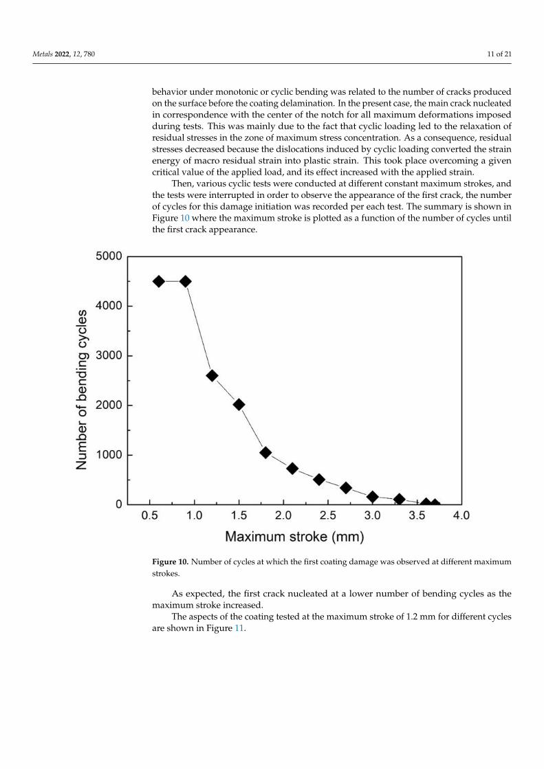
Then, various cyclic tests were conducted at different constant maximum strokes,
and the tests were interrupted in order to observe the appearance of the first crack, the
number of cycles for this damage initiation was recorded per each test. The summary is
shown in Figure 10 where the maximum stroke is plotted as a function of the number of
cycles until the first crack appearance.
Figure 9. Cyclic bending curves performed at different maximum vertical deformation.
Cracks were all located in the zone of maximum bending and maximum stress concen-tration (the center of the notch), with the main central crack opening upon increasing themaximum load and the number of cycles. In our previous study [37], the coating ductility
Metals 2022, 12, 780 11 of 21
behavior under monotonic or cyclic bending was related to the number of cracks producedon the surface before the coating delamination. In the present case, the main crack nucleatedin correspondence with the center of the notch for all maximum deformations imposedduring tests. This was mainly due to the fact that cyclic loading led to the relaxation ofresidual stresses in the zone of maximum stress concentration. As a consequence, residualstresses decreased because the dislocations induced by cyclic loading converted the strainenergy of macro residual strain into plastic strain. This took place overcoming a givencritical value of the applied load, and its effect increased with the applied strain.
Then, various cyclic tests were conducted at different constant maximum strokes, andthe tests were interrupted in order to observe the appearance of the first crack, the numberof cycles for this damage initiation was recorded per each test. The summary is shown inFigure 10 where the maximum stroke is plotted as a function of the number of cycles untilthe first crack appearance.
Metals 2022, 12, 780 14 of 25
Figure 10. Number of cycles at which the first coating damage was observed at different maximum
strokes.
As expected, the first crack nucleated at a lower number of bending cycles as the
maximum stroke increased.
The aspects of the coating tested at the maximum stroke of 1.2 mm for different cycles
are shown in Figure 11.
Figure 11. Coating behavior for different bending cycles at the maximum stroke of 1.2 mm. The
crack was confined at the notch tip and continued to grow as the number of loading cycles increased.
Figure 10. Number of cycles at which the first coating damage was observed at different maximumstrokes.
As expected, the first crack nucleated at a lower number of bending cycles as themaximum stroke increased.
The aspects of the coating tested at the maximum stroke of 1.2 mm for different cyclesare shown in Figure 11.

Metals 2022, 12, 780 12 of 21
Metals 2022, 12, 780 14 of 25
Figure 10. Number of cycles at which the first coating damage was observed at different maximum
strokes.
As expected, the first crack nucleated at a lower number of bending cycles as the
maximum stroke increased.
The aspects of the coating tested at the maximum stroke of 1.2 mm for different cycles
are shown in Figure 11.
Figure 11. Coating behavior for different bending cycles at the maximum stroke of 1.2 mm. The
crack was confined at the notch tip and continued to grow as the number of loading cycles increased. Figure 11. Coating behavior for different bending cycles at the maximum stroke of 1.2 mm. The crackwas confined at the notch tip and continued to grow as the number of loading cycles increased.
The crack nucleated in the center of the notch and then propagated toward the coatingthickness up to final delamination. Very few papers provided a conclusive explanationof this decoherent behavior of cold-spray coatings. A highly accepted model considersthe adhesion energy to cause failure at the interface [53]. This energy is released at theinterface upon cyclic loading. If the strain energy release rate is lower than the adhesionenergy of the coating, then the propagating crack will transition from the coating into thesubstrate. Conversely, if the strain energy release rate is higher than the adhesion energy,the propagating crack will interact with the interface layer, and debonding of the coatingfrom the substrate may occur. This is due to the behavior of the coating approaching theinterface; as a consequence of the material discontinuity, the crack intensity is modified,and the crack moves along the substrate–coating interface [71]. As a matter of fact, themechanism of coating decohesion is very similar to that reported in [54] even if, in thepresent case, cyclic loading was performed in a three-point bending test instead of a four-point bending test. As a matter of fact, crack initiation took place on the surface and thenled to branching with consequent coating layer spallation. As shown by the fracture surfaceobservations, cracks initiated on the surface in correspondence with the void locations orin correspondence with defects due to undeformed particles that remained embedded inthe coating layer.
At higher magnification, it was possible to follow the damage evolution acting onthe coating during cyclic bending (Figure 12). Compared with Ni-based superalloys withnotched substrate described in [38], it is clear that the present coating revealed a lowerdensity of cracks before delamination. In addition, in [37], multiple delaminations wereobserved in the sample, while, in the present case, the main crack governed the coatingdelamination in its vicinity. This behavior was also explained as the optimal adhesionexperienced by the coating thanks to the selected processing parameters. In the case ofthe HEAs employed in the present paper, higher temperature and higher pressure wereemployed for the coating deposition. Thus, it is reasonable that particles impacted withincreased velocity, experiencing a more pronounced severe plastic deformation leading tohigher splat and better adhesion to the substrate because of the enhanced peening effect.This was confirmed by the increased flattening ratio experienced by the particles of thepresent work and described in Figure 3. Therefore, in conclusion, the employed processparameters (1100 ◦C and 7 MPa) led to a more compact coating with remarkable particledeformation upon impact with a consequent high adhesion of the coating to the substrate

Metals 2022, 12, 780 13 of 21
and high residual stress levels. This led to a fatigue behavior of the coating completelydifferent from that revealed by particles with similar strength and dimensions employed toproduce cold-sprayed coatings obtained at lower temperature and pressure. Hence, even ifa more macroscopic brittleness could be revealed, a better coating adhesion was obtained,especially under cyclic loading. This was also due to the high temperature employed inthe present study that led to optimal adhesion of the coatings to the substrate [55]. In fact,as the deposition temperature increased, multiple cracks on the coating surface tended todisappear, and only one main crack governed the coating fracture behavior. Thus, highdeposition temperatures led to higher adhesion and better performance in terms of crackinitiation, as demonstrated in [13,34,37].
Metals 2022, 12, 780 15 of 25
The crack nucleated in the center of the notch and then propagated toward the coat-
ing thickness up to final delamination. Very few papers provided a conclusive explanation
of this decoherent behavior of cold-spray coatings. A highly accepted model considers the
adhesion energy to cause failure at the interface [53]. This energy is released at the inter-
face upon cyclic loading. If the strain energy release rate is lower than the adhesion energy
of the coating, then the propagating crack will transition from the coating into the sub-
strate. Conversely, if the strain energy release rate is higher than the adhesion energy, the
propagating crack will interact with the interface layer, and debonding of the coating from
the substrate may occur. This is due to the behavior of the coating approaching the inter-
face; as a consequence of the material discontinuity, the crack intensity is modified, and
the crack moves along the substrate–coating interface [71]. As a matter of fact, the mecha-
nism of coating decohesion is very similar to that reported in [54] even if, in the present
case, cyclic loading was performed in a three-point bending test instead of a four-point
bending test. As a matter of fact, crack initiation took place on the surface and then led to
branching with consequent coating layer spallation. As shown by the fracture surface ob-
servations, cracks initiated on the surface in correspondence with the void locations or in
correspondence with defects due to undeformed particles that remained embedded in the
coating layer.
At higher magnification, it was possible to follow the damage evolution acting on the
coating during cyclic bending (Figure 12).
Figure 12. Damage evolution in the coating after different cycles of bending loading at 1.2 mm max-
imum stroke. As is clear from the pictures, the crack nucleated at the center of the notch without
any additional crack at the notch periphery.
Figure 12. Damage evolution in the coating after different cycles of bending loading at 1.2 mmmaximum stroke. As is clear from the pictures, the crack nucleated at the center of the notch withoutany additional crack at the notch periphery.
The fracture surface of the notched sample after rupture is shown in Figure 13.Here, the main fracture mechanism was due to particle-particle decohesion with local
ductility features experienced at the particle-particle interfaces (Figure 14).

Metals 2022, 12, 780 14 of 21
Metals 2022, 12, 780 16 of 25
Compared with Ni-based superalloys with notched substrate described in [38], it is
clear that the present coating revealed a lower density of cracks before delamination.
In addition, in [37], multiple delaminations were observed in the sample, while, in
the present case, the main crack governed the coating delamination in its vicinity. This
behavior was also explained as the optimal adhesion experienced by the coating thanks
to the selected processing parameters. In the case of the HEAs employed in the present
paper, higher temperature and higher pressure were employed for the coating deposition.
Thus, it is reasonable that particles impacted with increased velocity, experiencing a more
pronounced severe plastic deformation leading to higher splat and better adhesion to the
substrate because of the enhanced peening effect. This was confirmed by the increased
flattening ratio experienced by the particles of the present work and described in Figure
3. Therefore, in conclusion, the employed process parameters (1100 °C and 7 MPa) led to
a more compact coating with remarkable particle deformation upon impact with a conse-
quent high adhesion of the coating to the substrate and high residual stress levels. This
led to a fatigue behavior of the coating completely different from that revealed by particles
with similar strength and dimensions employed to produce cold-sprayed coatings ob-
tained at lower temperature and pressure. Hence, even if a more macroscopic brittleness
could be revealed, a better coating adhesion was obtained, especially under cyclic loading.
This was also due to the high temperature employed in the present study that led to opti-
mal adhesion of the coatings to the substrate [55]. In fact, as the deposition temperature
increased, multiple cracks on the coating surface tended to disappear, and only one main
crack governed the coating fracture behavior. Thus, high deposition temperatures led to
higher adhesion and better performance in terms of crack initiation, as demonstrated in
[13,34,37].
The fracture surface of the notched sample after rupture is shown in Figure 13.
Figure 13. Fracture surface of the notched sample tested at the maximum stroke of 1.2 mm.
Here, the main fracture mechanism was due to particle–particle decohesion with lo-
cal ductility features experienced at the particle–particle interfaces (Figure 14).
Figure 13. Fracture surface of the notched sample tested at the maximum stroke of 1.2 mm.Metals 2022, 12, 780 17 of 25
Figure 14. Local ductility features observed at the particle–particle interfaces after fracture.
The fatigue crack mechanism is dependent on the applied stress and the crack size in
comparison with the material microstructural features [72]. In many cases, the shift from
transparticular to interparticular crack propagation depends on the stress intensity. This
is attributed to the change in the dimension of the plastic zone ahead of the crack propa-
gation tip. In this case, weaker particles and more microvoids can be encountered along
the crack propagation path, leading to particle–particle decohesion instead of interparticle
fracture. Therefore, this general behavior can lead to very brittle coating behavior at low
intensity; otherwise, more ductile features can be observed at low intensities. This has
been demonstrated by post-spray heat treatments leading to an increase in coating ductil-
ity with consequent decreased fatigue crack growth, thanks to improved interparticle
bonding [35]. This is also due to basic powder metallurgy mechanisms leading to a de-
crease in the void effect on the local diffusion around the microvoids formed during the
spray operations. In addition, the different precipitation states of heat-treated alloys can
act as a barrier to the crack propagation [73]. Furthermore, a finer microstructure with an
optimal deposition can act as a crack retardant. In general, for the same powders, cold-
spray coatings show a finer microstructure due to the higher impact velocity as a conse-
quence of the more severe plastic deformation upon impact. In this case, a compact coat-
ing coupled with a fine microstructure can provide a greater number of grain boundaries
impeding the slip during loading [74]. This is demonstrated by a more faceted fracture
surface aspect due to the increased resistance of each particle.
Many particles showed the formation of local striations typical of the cyclic loading
the samples were subjected to (Figure 15).
Figure 14. Local ductility features observed at the particle-particle interfaces after fracture.
The fatigue crack mechanism is dependent on the applied stress and the crack size incomparison with the material microstructural features [72]. In many cases, the shift fromtransparticular to interparticular crack propagation depends on the stress intensity. This isattributed to the change in the dimension of the plastic zone ahead of the crack propagationtip. In this case, weaker particles and more microvoids can be encountered along thecrack propagation path, leading to particle-particle decohesion instead of interparticlefracture. Therefore, this general behavior can lead to very brittle coating behavior at lowintensity; otherwise, more ductile features can be observed at low intensities. This has beendemonstrated by post-spray heat treatments leading to an increase in coating ductility withconsequent decreased fatigue crack growth, thanks to improved interparticle bonding [35].

Metals 2022, 12, 780 15 of 21
This is also due to basic powder metallurgy mechanisms leading to a decrease in the voideffect on the local diffusion around the microvoids formed during the spray operations. Inaddition, the different precipitation states of heat-treated alloys can act as a barrier to thecrack propagation [73]. Furthermore, a finer microstructure with an optimal depositioncan act as a crack retardant. In general, for the same powders, cold-spray coatings showa finer microstructure due to the higher impact velocity as a consequence of the moresevere plastic deformation upon impact. In this case, a compact coating coupled with afine microstructure can provide a greater number of grain boundaries impeding the slipduring loading [74]. This is demonstrated by a more faceted fracture surface aspect due tothe increased resistance of each particle.
Many particles showed the formation of local striations typical of the cyclic loadingthe samples were subjected to (Figure 15).
Metals 2022, 12, 780 18 of 25
Figure 15. Local fatigue mechanisms observed on single particles after fracture.
On the contrary, particles impacting with lower velocity led to coatings with de-
creased bonding strength, fracture toughness, and a very brittle fracture surface [75].
Again, the fracture behavior was governed by the particle–particle bonding strength. This
was governed by the shear instability upon impact that led to heat being retained by the
particles, leading to an improvement of the particle–particle bond strength.
In this case, the main fracture mechanism was due to particle–particle decohesion.
The main difference is that, as the maximum stroke increased, the formation of large voids
on the surface increased (Figure 16).
Figure 15. Local fatigue mechanisms observed on single particles after fracture.
On the contrary, particles impacting with lower velocity led to coatings with decreasedbonding strength, fracture toughness, and a very brittle fracture surface [75]. Again,the fracture behavior was governed by the particle-particle bonding strength. This wasgoverned by the shear instability upon impact that led to heat being retained by theparticles, leading to an improvement of the particle-particle bond strength.
In this case, the main fracture mechanism was due to particle-particle decohesion. Themain difference is that, as the maximum stroke increased, the formation of large voids onthe surface increased (Figure 16).

Metals 2022, 12, 780 16 of 21Metals 2022, 12, 780 19 of 25
Figure 16. Voids at the particle–particle interface for the notched sample tested at the maximum
stroke of 1.8 mm.
By observing the zones of the fracture surface where voids were individuated, it
should be highlighted that these voids tended to form where particles appeared with their
original aspect (Figure 17).
Figure 17. Decohesion at the interfaces of undeformed particles in the samples cyclically bent at the
maximum stroke of 1.8 mm.
Hence, in these zones, particles experienced low deformation, while particle–particle
interlocking and local cohesion did not take place. These zones had low resistance to load-
ing and, as a consequence, large voids were formed.
Accordingly, even if local fatigue mechanisms could be individuated on each particle
surface, particle–particle decohesion also took place in the case of largely deformed parti-
cles (Figure 18).
Figure 16. Voids at the particle-particle interface for the notched sample tested at the maximumstroke of 1.8 mm.
By observing the zones of the fracture surface where voids were individuated, itshould be highlighted that these voids tended to form where particles appeared with theiroriginal aspect (Figure 17).
Metals 2022, 12, 780 19 of 25
Figure 16. Voids at the particle–particle interface for the notched sample tested at the maximum
stroke of 1.8 mm.
By observing the zones of the fracture surface where voids were individuated, it
should be highlighted that these voids tended to form where particles appeared with their
original aspect (Figure 17).
Figure 17. Decohesion at the interfaces of undeformed particles in the samples cyclically bent at the
maximum stroke of 1.8 mm.
Hence, in these zones, particles experienced low deformation, while particle–particle
interlocking and local cohesion did not take place. These zones had low resistance to load-
ing and, as a consequence, large voids were formed.
Accordingly, even if local fatigue mechanisms could be individuated on each particle
surface, particle–particle decohesion also took place in the case of largely deformed parti-
cles (Figure 18).
Figure 17. Decohesion at the interfaces of undeformed particles in the samples cyclically bent at themaximum stroke of 1.8 mm.
Hence, in these zones, particles experienced low deformation, while particle-particleinterlocking and local cohesion did not take place. These zones had low resistance toloading and, as a consequence, large voids were formed.
Accordingly, even if local fatigue mechanisms could be individuated on each particlesurface, particle-particle decohesion also took place in the case of largely deformed particles(Figure 18).

Metals 2022, 12, 780 17 of 21Metals 2022, 12, 780 20 of 25
Figure 18. Fatigue mechanisms in deformed particles and particle–particle decohesion in the sample
cyclically bent at the maximum stroke of 1.8 mm.
This behavior was due to the microstructure of the starting particles and to their be-
havior upon slatting. In fact, variation in the powder particle microstructure can lead to
different impact physics and ultimate impact morphology [76]. In fact, the morphology of
deformed particles can shift from a perfect half-sphere with radial jetting zones to the
same half-sphere with irregular protuberances to triangular shapes with threefold sym-
metry to square-like shapes with fourfold symmetry. Obviously, as the morphology
changes, so do the particle–particle bonding and the overall coating resistance. This vari-
ation in the morphology is dependent on the starting particle microstructure, as it moves
from an equiaxed microstructure, the deformed particle morphology shifts from a perfect
half-sphere with radial jets toward other morphologies. Therefore, as the microstructure
moves from an equiaxed grain, the particle–particle adhesion surfaces are reduced, voids
form, and the fracture surface aspect appears more brittle. In this view, the impact and
bonding behavior of particles and the consequent fracture aspect can also largely vary for
a nonuniform grain size and shape distribution.
Another fundamental factor is represented by the effect on crack initiation and prop-
agation related to the properties of the feedstock powders [77–79]. Crack initiation as
transparticle fracture is dependent on the splatting of the particles; at high loads, high-
quality splatted powders reveal a mixture of interparticular and trasnparticular fracture
aspects during crack propagation. This reveals the quality of the particle–particle bonding
at high deformations. As a matter of fact, only strongly bonded particle–particle interfaces
are able to transfer the load producing local plastic deformation indicated by the occur-
rence of nonbrittle features on the fracture surface. This is demonstrated by other scientific
studies where crack propagation was improved because of proper post-deposition heat
treatments leading to an increase in particle–particle bonding because of local diffusion
processes taking place at the particle–particle interfaces [72]. This was confirmed by crack
Figure 18. Fatigue mechanisms in deformed particles and particle-particle decohesion in the samplecyclically bent at the maximum stroke of 1.8 mm.
This behavior was due to the microstructure of the starting particles and to theirbehavior upon slatting. In fact, variation in the powder particle microstructure can lead todifferent impact physics and ultimate impact morphology [76]. In fact, the morphology ofdeformed particles can shift from a perfect half-sphere with radial jetting zones to the samehalf-sphere with irregular protuberances to triangular shapes with threefold symmetry tosquare-like shapes with fourfold symmetry. Obviously, as the morphology changes, so dothe particle-particle bonding and the overall coating resistance. This variation in the mor-phology is dependent on the starting particle microstructure, as it moves from an equiaxedmicrostructure, the deformed particle morphology shifts from a perfect half-sphere withradial jets toward other morphologies. Therefore, as the microstructure moves from anequiaxed grain, the particle-particle adhesion surfaces are reduced, voids form, and thefracture surface aspect appears more brittle. In this view, the impact and bonding behaviorof particles and the consequent fracture aspect can also largely vary for a nonuniform grainsize and shape distribution.
Another fundamental factor is represented by the effect on crack initiation and prop-agation related to the properties of the feedstock powders [77–79]. Crack initiation astransparticle fracture is dependent on the splatting of the particles; at high loads, high-quality splatted powders reveal a mixture of interparticular and trasnparticular fractureaspects during crack propagation. This reveals the quality of the particle-particle bonding athigh deformations. As a matter of fact, only strongly bonded particle-particle interfaces areable to transfer the load producing local plastic deformation indicated by the occurrence ofnonbrittle features on the fracture surface. This is demonstrated by other scientific studieswhere crack propagation was improved because of proper post-deposition heat treatmentsleading to an increase in particle-particle bonding because of local diffusion processes

Metals 2022, 12, 780 18 of 21
taking place at the particle-particle interfaces [72]. This was confirmed by crack initiationand growth behavior of aluminum alloys where the crack initiation is accompanied by a flataspect of the crack path, which becomes more tortuous as the crack propagates toward finalfailure. This change from transparticular to mixed interparticular and transparticular crackpropagation is in correspondence with the increase in the local loading conditions as thecrack propagates. This has also been observed in other hard materials such as cold-sprayedmetal matrix composites where brittleness was much more pronounced with respect tothe unreinforced base materials [75], as well as in stainless-steel cold-spray deposits [77].In this case, it can be underlined that both grain size (due to particle splatting) and strainhardening (due to loading) are responsible for the transparticular deformation.
4. Conclusions
Cold-spray coatings were produced at 1100 ◦C and 7 MPa, obtaining FeCoCrNiMnequiatomic high-entropy alloy deposits with very low porosity and high hardness, andwith a thickness of 500 µm. This was due to the large flattening ratio induced in the splattedparticles thanks to the employed processing parameters. This demonstrates that the tunedemployed process parameters were optimally settled for this specific high-entropy alloyon the employed substrate. Obviously, the flattening ratio was more pronounced in thoseregions very close to the substrate where the severe plastic deformation of the sprayedmaterial increased because of the continuous peening effect due to further impactingparticles.
The XRD analyses of the as-received powders and of the as-sprayed coatings revealedthe retention of the face-centered cubic structure of the high-entropy alloy. The broaden-ing of the XRD peaks revealed through layer-by-layer measurements allowed definingthe residual stress profile along the coating with maximum compressive stresses closeto 200 MPa at a distance of 100 µm from the substrate–coating interface. The residualstress profile appeared optimal for the fatigue strength of the coatings with compressivecharacteristics in the inner layers.
The three-point bending cyclic tests, performed at a fixed value of the maximum strokeon V-notched substrates, allowed defining the number of cycles before the appearance ofthe first surface crack for a given value of the maximum imposed stroke. As expected, thefirst surface crack nucleated at a lower number of cycles as the maximum stroke decreased.The crack aspect revealed a good adhesion of the coating to the substrate.
The fracture mechanisms revealed a mixed brittleness character of the crack propaga-tion path with local ductile and fatigue features revealed on the fracture surface. Cracksnucleated mainly at the surface defects with a mainly transparticular path at the first stagesof deformation, whereas a mixed transparticular and interparticular fracture behaviorwas revealed by the fracture surface. It is believed that microvoids and undeformed splatparticles were responsible for the acceleration of the crack propagation.
Author Contributions: Conceptualization, P.C., A.S., I.G.C. and A.P.; methodology, P.C. and G.B.;validation, P.C.; formal analysis, G.B., A.L., A.P. and A.S.; investigation, G.B., A.L., A.P. and A.S.;resources, P.C., and I.G.C.; data curation, P.C. and A.P.; writing—original draft preparation, P.C.; writing—review and editing, P.C.; supervision, P.C. and I.G.C.; project administration, P.C. and I.G.C.; fundingacquisition, P.C. and I.G.C. All authors have read and agreed to the published version of the manuscript.
Funding: This research was funded by Agència de Gestió d’Ajuts Universitaris i de Recerca (Spain),grant number SGR 2017-01777 AGAUR and by Ministerio de Ciencia e Innovación (Spain), grantnumber PID 2020-115508RB-C21.
Institutional Review Board Statement: Not applicable.
Informed Consent Statement: Not applicable.
Data Availability Statement: Data will be available on request to the corresponding author.
Conflicts of Interest: The authors declare no conflict of interest.

Metals 2022, 12, 780 19 of 21
References1. Yeh, J.-W.; Chen, S.-K.; Lin, S.-J.; Gan, J.-Y.; Chin, T.-S.; Shun, T.-T.; Tsau, C.-H.; Chang, S.-Y. Nanostructured high-entropy alloys
with multiple principal elements: Novel alloy design concepts and outcomes. Adv. Eng. Mater. 2004, 6, 299–303. [CrossRef]2. Zhang, Y.; Zuo, T.T.; Tang, Z.; Gao, M.C.; Dahmen, K.A.; Liaw, P.K.; Lu, Z.P. Microstructures and properties of high-entropy alloys.
Prog. Mater. Sci. 2014, 61, 1–93. [CrossRef]3. Miracle, D.B.; Senkov, O.N. A critical review of high entropy alloys and related concepts. Acta Mater. 2017, 122, 488–511.
[CrossRef]4. Otto, F.; Dlouhý, A.; Somsen, C.; Bei, H.; Eggeler, G.; George, E.P. The influences of temperature and microstructure on the tensile
properties of a CoCrFeMnNi high-entropy alloy. Acta Mater. 2013, 61, 5743–5755. [CrossRef]5. Gludovatz, B.; Hohenwarter, A.; Catoor, D.; Chang, E.H.; George, E.P.; Ritchie, R.O. A fracture-resistant high-entropy alloy for
cryogenic applications. Science 2014, 345, 1153–1158. [CrossRef] [PubMed]6. Yazdani, N.; Toroghinejad, M.R.; Shabani, A.; Cavaliere, P. Effects of Process Control Agent Amount, Milling Time, and Annealing
Heat Treatment on the Microstructure of AlCrCuFeNi High-Entropy Alloy Synthesized through Mechanical Alloying. Metals2021, 11, 1493. [CrossRef]
7. Moazzen, P.; Toroghinejad, M.R.; Cavaliere, P. Effect of Iron content on the microstructure evolution, mechanical properties andwear resistance of FeXCoCrNi high-entropy alloy system produced via MA-SPS. J. Alloy. Compd. 2021, 870, 159410. [CrossRef]
8. Moazzen, P.; Toroghinejad, M.R.; Zargar, T.; Cavaliere, P. Investigation of hardness, wear and magnetic properties of NiCoCrFeZrxHEA prepared through mechanical alloying and spark plasma sintering. J. Alloy. Compd. 2022, 892, 161924. [CrossRef]
9. Silvello, A.; Cavaliere, P.; Yin, S.; Lupoi, R.; Garcia Cano, I.; Dosta, S. Microstructural, Mechanical and Wear Behavior of HVOFand Cold-Sprayed High-Entropy Alloys (HEAs) Coatings. J. Therm. Spray Tech. 2022, 1–23. [CrossRef]
10. Shi, Y.; Yang, B.; Liaw, P. Corrosion-Resistant High-Entropy Alloys: A Review. Metals 2017, 7, 43. [CrossRef]11. Qiu, Y.; Thomas, S.; Gibson, M.A.; Fraser, H.L.; Birbilis, N. Corrosion of high entropy alloys. Npj. Mater. Degrad. 2017, 1, 15.
[CrossRef]12. Yin, S.; Cavaliere, P.; Aldwell, B.; Jenkins, R.; Liao, H.; Li, W.; Lupoi, R. Cold spray additive manufacturing and repair:
Fundamentals and applications. Addit. Manuf. 2018, 21, 628–650. [CrossRef]13. Cavaliere, P.; Silvello, A. Crack Repair in Aerospace Aluminum Alloy Panels by Cold Spray. J. Therm. Spray Technol. 2017, 26,
661–670. [CrossRef]14. Cavaliere, P. Cold-Spray Coatings: Recent Trends and Future Perspectives; Springer International Publishing: Cham, Switzerland,
2018. [CrossRef]15. Assadi, H.; Gärtner, F.; Stoltenhoff, T.; Kreye, H. Bonding mechanism in cold gas spraying. Acta Mater. 2003, 51, 4379–4394.
[CrossRef]16. Grujicic, M.; Zhao, C.L.; DeRosset, W.S.; Helfritch, D. Adiabatic shear instability based mechanism for particles/substrate bonding
in the cold-gas dynamic-spray process. Mater. Des. 2004, 25, 681–688. [CrossRef]17. Grujicic, M.; Saylor, J.R.; Beasley, D.E.; DeRosset, W.S.; Helfritch, D. Computational analysis of the interfacial bonding between
feed-powder particles and the substrate in the cold-gas dynamic-spray process. Appl. Surf. Sci. 2003, 219, 211–227. [CrossRef]18. Hassani-Gangaraj, M.; Veysset, D.; Champagne, V.K.; Nelson, K.A.; Schuh, C.A. Adiabatic shear instability is not necessary for
adhesion in cold spray. Acta Mater. 2018, 158, 430–439. [CrossRef]19. Hassani-Gangaraj, M.; Veysset, D.; Nelson, K.A.; Schuh, C.A. In-situ observations of single micro-particle impact bonding. Scr.
Mater. 2018, 145, 9–13. [CrossRef]20. Stoltenhoff, T.; Kreye, H.; Richter, H.J. An analysis of the cold spray process and its coatings. J. Therm. Spray Technol. 2002, 11,
542–550. [CrossRef]21. Moridi, A.; Hassani-Gangaraj, S.M.; Guagliano, M.; Dao, M. Cold spray coating: Review of material systems and future
perspectives. Surf. Eng. 2014, 30, 369–395. [CrossRef]22. Luzin, V.; Spencer, K.; Zhang, M.-X. Residual stress and thermo-mechanical properties of cold spray metal coatings. Acta Mater.
2011, 59, 1259–1270. [CrossRef]23. Luo, X.; Li, C.; Shang, F.; Yang, G.; Wang, Y.; Li, C. High velocity impact induced microstructure evolution during deposition of
cold spray coatings: A review. Surf. Coat. Technol. 2014, 254, 11–20. [CrossRef]24. Marzbanrad, B.; Jahed, H.; Toyserkani, E. On the evolution of substrate’s residual stress during cold spray process: A parametric
study. Mater. Des. 2018, 138, 90–102. [CrossRef]25. Cavaliere, P.; Silvello, A. Fatigue behaviour of cold sprayed metals and alloys: Critical review. Surf. Eng. 2016, 32, 631–640.
[CrossRef]26. Ghelichi, R.; MacDonald, D.; Bagherifard, S.; Jahed, H.; Guagliano, M.; Jodoin, B. Microstructure and fatigue behavior of cold
spray coated Al5052. Acta Mater. 2012, 60, 6555–6561. [CrossRef]27. Moridi, A.; Hassani-Gangaraj, S.M.; Vezzú, S.; Trško, L.; Guagliano, M. Fatigue behavior of cold spray coatings: The effect of
conventional and severe shot peening as pre-/post-treatment. Surf. Coat. Technol. 2015, 283, 247–254. [CrossRef]28. Dayani, S.B.; Shaha, S.K.; Ghelichi, R.; Wang, J.F.; Jahed, H. The impact of AA7075 cold spray coating on the fatigue life of AZ31B
cast alloy. Surf. Coat. Technol. 2018, 337, 150–158. [CrossRef]29. Cavaliere, P.; Silvello, A. Processing conditions affecting residual stresses and fatigue properties of cold spray deposits. Int. J. Adv.
MAnuf. Technol. 2015, 81, 1857–1862. [CrossRef]

Metals 2022, 12, 780 20 of 21
30. Tetrácková, K.; Kondás, J.; Guagliano, M. Mechanical Performance of Cold-Sprayed A357 Aluminum Alloy Coatings for Repairand Additive Manufacturing. J. Therm. Spray Technol. 2017, 26, 1888–1897. [CrossRef]
31. Yandouzi, M.; Gaydos, S.; Guo, D.; Ghelichi, R.; Jodoin, B. Aircraft Skin Restoration and Evaluation. J. Therm. Spray Technol. 2014,23, 1281–1290. [CrossRef]
32. Bagherifard, S.; Guagliano, M. Fatigue performance of cold spray deposits: Coating, repair and additive manufacturing cases. Int.J. Fatigue 2020, 139, 105744. [CrossRef]
33. Sample, C.M.; Champagne, V.K.; Nardi, A.T.; Lados, D.A. Factors governing static properties and fatigue, fatigue crack growth,and fracture mechanisms in cold spray alloys and coatings/repairs: A review. Addit. Manuf. 2020, 36, 101371. [CrossRef]
34. Cavaliere, P.; Silvello, A. Finite element analyses of pure Ni cold spray particles impact related to coating crack behaviour. Surf.Eng. 2018, 34, 361–368. [CrossRef]
35. Cavaliere, P.; Perrone, A.; Silvello, A. Fatigue behaviour of Inconel 625 cold spray coatings. Surf. Eng. 2018, 34, 380–391. [CrossRef]36. Silvello, A.; Cavaliere, P.; Rizzo, A.; Valerini, D.; Dosta Parras, S.; Garcia Cano, I. Fatigue Bending Behavior of Cold-Sprayed
Nickel-Based Superalloy Coatings. J. Therm. Spray Technol. 2019, 28, 930–938. [CrossRef]37. Cavaliere, P.; Silvello, A.; Cinca, N.; Canales, H.; Dosta, S.; Garcia Cano, I.; Guilemany, J.M. Microstructural and fatigue behavior
of cold sprayed Ni-based superalloys coatings. Surf. Coat. Technol. 2017, 324, 390–402. [CrossRef]38. Xu, Y.; Li, W.; Qu, L.; Yang, X.; Song, B.; Lupoi, R.; Yin, S. Solid-state cold spraying of FeCoCrNiMn high-entropy alloy: An insight
into microstructure evolution and oxidation behavior at 700–900 ◦C. J. Mater. Sci. Technol. 2021, 68, 172–183. [CrossRef]39. Ahn, J.E.; Kim, Y.K.; Yoon, S.H.; Lee, K.A. Tuning the Microstructure and Mechanical Properties of Cold Sprayed Equiatomic
CoCrFeMnNi High-Entropy Alloy Coating Layer. Met. Mater. Int. 2021, 27, 2406–2415. [CrossRef]40. Rojas, D.F.; Li, H.; Orhan, O.K.; Shao, C.; Hogan, J.D.; Ponga, M. Mechanical and microstructural properties of a
CoCrFe0.75NiMo0.3Nb0.125 high-entropy alloy additively manufactured via cold-spray. J. Alloy. Compd. 2022, 893,162309. [CrossRef]
41. Kim, Y.-K.; Ham, G.-S.; Kim, H.S.; Lee, K.-A. High-cycle fatigue and tensile deformation behaviors of coarse-grained equiatomicCoCrFeMnNi high-entropy alloy and unexpected hardening behavior during cyclic loading. Intermetallics 2019, 111, 106486.[CrossRef]
42. Lu, Y.P.; Gao, X.; Jiang, L.; Chen, Z.; Wang, T.; Jie, J.; Kang, H.; Zhang, Y.; Guo, S.; Ruan, H.; et al. Directly cast bulk eutecticand near-eutectic high entropy alloys with balanced strength and ductility in a wide temperature range. Acta Mater. 2017, 124,143–150. [CrossRef]
43. Brocq, M.L.; Goujon, P.-A.; Monnier, J.; Villeroy, B.; Perrire, L.; Pirs, R.; Garchin, G. Microstructure and mechanical properties of aCoCrFeMnNi high entropy alloy processed by milling and spark plasma sintering. J. Alloy. Comp. 2019, 780, 856–865. [CrossRef]
44. Ghelichi, R.; Bagherifard, S.; Donald, D.M.; Brochu, M.; Jahed, H.; Jodoin, B.; Guagliano, M. Fatigue strength of Al alloy coldsprayed with nanocrystalline powders. Int. J. Fatigue 2014, 65, 51–57. [CrossRef]
45. Yu, P.; Fan, N.; Zhang, Y.; Wang, Z.; Li, W.; Lupoi, R.; Yin, S. Microstructure evolution and composition redistribution ofFeCoNiCrMn high entropy alloy under extreme plastic deformation. Mater. Res. Lett. 2022, 10, 124–132. [CrossRef]
46. Assadi, H.; Kreye, H.; Gartner, F.; Klassen, T. Cold spraying a materials perspective. Acta Mater. 2016, 116, 382–407. [CrossRef]47. Wong, W.; Vo, P.; Irissou, E.; Ryabinin, A.N.; Legoux, J.-G.; Yue, S. Effect of particle morphology and size distribution on
cold-sprayed pure titanium coatings. J. Therm. Spray Technol. 2013, 22, 1140–1153. [CrossRef]48. Assadi, H.; Schmidt, T.; Richter, H.; Kliemann, J.O.; Binder, K.; Gärtner, F.; Klassen, T.; Kreye, H. On parameter selection in cold
spraying. J. Therm. Spray Technol. 2011, 20, 1161–1176. [CrossRef]49. Spencer, K.; Luzin, V.; Matthews, N.; Zhang, M.X. Residual stresses in cold spray al coatings: The effect of alloying and of process
parameters. Surf. Coat. Technol. 2012, 206, 4249–4255. [CrossRef]50. Eason, P.D.; Fewkes, J.A.; Kennett, S.C.; Eden, T.J.; Tello, K.; Kaufman, M.J.; Tiryakioglu, M. On the characterization of bulk
copper produced by cold gas dynamic spray processing in as fabricated and annealed conditions. Mater. Sci. Eng. A 2011, 528,8174–8178. [CrossRef]
51. Cavaliere, P.; Perrone, A.; Silvello, A. Crystallization evolution of cold sprayed pure Ni coatings. J. Therm. Spray Technol. 2016, 25,1158–1167. [CrossRef]
52. Singh, R.; Schruefer, S.; Wilson, S.; Gibmeier, J.; Vassen, R. Influence of coating thickness on residual stress and adhesion-strengthof cold-sprayed Inconel 718 coatings. Surf. Coat. Technol. 2018, 350, 64–73. [CrossRef]
53. White, B.C.; Story, W.A.; Brewer, L.N.; Jordon, J.B. Fracture mechanics methods for evaluating the adhesion of cold spray deposits.Eng. Fract. Mech. 2019, 205, 57–69. [CrossRef]
54. Lin, E.; Chen, Q.; Ozdemir, O.C.; Champagne, V.K.; Müftü, S. Effects of Interface Bonding on the Residual Stresses in Cold-SprayedAl-6061: A Numerical Investigation. J. Therm. Spray Technol. 2019, 28, 472–483. [CrossRef]
55. Jafarlou, D.M.; Ferguson, G.; Tsaknopoulos, K.L.; Chuang, A.C.; Nardi, A.; Cote, D.; Champagne, V.; Grosse, I.R. Structuralintegrity of additively manufactured stainless steel with cold sprayed barrier coating under combined cyclic loading. Addit.Manuf. 2020, 35, 101338. [CrossRef]
56. Luzin, V.; Kirstein, O.; Zahiri, S.H.; Fraser, D. Residual Stress Buildup in Ti Components Produced by Cold Spray AdditiveManufacturing (CSAM). J. Therm. Spray Technol. 2020, 29, 1498–1507. [CrossRef]

Metals 2022, 12, 780 21 of 21
57. Cizek, J.; Matejkova, M.; Dlouhy, I.; Siska, F.; Kay, C.M.; Karthikeyan, J.; Kuroda, S.; Kovarik, O.; Siegl, J.; Loke, K.; et al. Influenceof cold-sprayed, warm-sprayed, and plasma-sprayed layers deposition on fatigue properties of steel specimens. J. Therm. SprayTechnol. 2015, 24, 758–768. [CrossRef]
58. Fardan, A.; Berndt, C.C.; Ahmed, R. Numerical modelling of particle impact and residual stresses in cold sprayed coatings: Areview. Surf. Coat. Technol. 2021, 409, 126835. [CrossRef]
59. Seraj, R.A.; Abdollah-zadeh, A.; Dosta, S.; Canales, H.; Assadi, H.; Cano, I.G. The effect of traverse speed on deposition efficiencyof cold sprayed Stellite 21. Surf. Coat. Technol. 2019, 366, 24–34. [CrossRef]
60. Gao, P.-H.; Li, C.-J.; Yang, G.-J.; Li, Y.-G.; Li, C.-X. Influence of substrate hardness on deposition behavior of single porousWC-12Co particle in cold spraying. Surf. Coat. Technol. 2008, 203, 384–390. [CrossRef]
61. Champagne, V.K.; Helfritch, D.J.; Trexler, M.D.; Gabriel, B.M. The effect of cold spray impact velocity on deposit hardness. Modell.Simul. Mater. Sci. Eng. 2010, 18, 65011. [CrossRef]
62. Schmidt, T.; Gaertner, F.; Kreye, H. New developments in cold spray based on higher gas and particle temperatures. J. Therm.Spray Technol. 2006, 15, 488–494. [CrossRef]
63. Moridi, A.; Hassani-Gangaraj, S.M.; Guagliano, M. On fatigue behavior of cold spray coating. MRS Online Proc. Library 2014,1650, 503. [CrossRef]
64. Bagherifard, S.; Monti, S.; Zuccoli, M.V.; Riccio, M.; Kondás, J.; Guagliano, M. Cold spray deposition for additive manufacturingof freeform structural components compared to selective laser melting. Mater. Sci. Eng. A 2018, 721, 339–350. [CrossRef]
65. Yamazaki, Y.; Fukanuma, H.; Ohno, N. Anisotropic mechanical properties of the free-standing cold sprayed SUS316 coating andthe effect of the post-spray heat treatment on it. J. Jpn. Therm. Spray. Soc. 2016, 53, 91–95.
66. Price, T.S.; Shipway, P.H.; McCartney, D.G. Effect of cold spray deposition of a titanium coating on fatigue behavior of a titaniumalloy. J. Therm. Spray Technol. 2006, 15, 507–512. [CrossRef]
67. Xiong, Y.; Zhang, M.-X. The effect of cold sprayed coatings on the mechanical properties of AZ91D magnesium alloys. Surf. Coat.Technol. 2014, 253, 89–95. [CrossRef]
68. Shi, Z.-C.; Zhang, X.-Y.; Chen, H.; Ding, F.-Z.; Yu, B.; Tang, Z.-H.; Lu, F. Properties of cold spray Al/Zn coatings on high-strengthsteel. J. Mater. Eng. 2015, 43, 14–19. [CrossRef]
69. Ševecek, M.; Krejcí, J.; Shahin, M.; Petrik, J.; Ballinger, R.; Shirvan, K. Fatigue Behavior of Cold Spray-Coated Accident TolerantCladding. In Proceedings of the Topfuel 2018, Prague, Czech Republic, 30 September–4 October 2018.
70. Cizek, J.; Kovarik, O.; Siegl, J.; Khor, K.A.; Dlouhy, I. Influence of plasma and cold spray deposited Ti Layers on high-cycle fatigueproperties of Ti6Al4V substrates. Surf. Coat. Technol. 2013, 217, 23–33. [CrossRef]
71. Anderson, T.L. Fracture Mechanics Fundamentals and Applications; CRC Press: Boca Raton, FL, USA, 2017. [CrossRef]72. Gavras, A.G.; Lados, D.A.; Champagne, V.K.; Warren, R.J. Effects of processing on microstructure evolution and fatigue crack
growth mechanisms in cold-spray 6061 aluminum alloy. Int. J. Fatigue 2018, 110, 49–62. [CrossRef]73. Hussain, T.; McCartney, D.G.; Shipway, P.H.; Zhang, D. Bonding mechanisms in cold spraying: The contributions of metallurgical
and mechanical components. J. Therm. Spray Technol. 2009, 18, 364–379. [CrossRef]74. Gavras, A.G.; Lados, D.A.; Champagne, V.; Warren, R.J.; Singh, D. Small fatigue crack growth mechanisms and interfacial stability
in cold-spray 6061 aluminum alloys and coatings. Metall. Mater. Trans. A 2018, 49, 6509–6520. [CrossRef]75. Bangstein, B.B.; Ellingsen, M.; Scholl, N. Fracture Toughness of Cold Spray Aluminum 6061 Deposit; South Dakota School of Mines
and Technology: Rapid City, SD, USA, 2015.76. Nikbakht, R.; Saadati, M.; Kim, T.-S.; Jahazi, M.; Kim, H.S.; Jodoin, B. Cold spray deposition characteristic and bonding of
CrMnCoFeNi high entropy alloy. Surf. Coat. Technol. 2021, 425, 127748. [CrossRef]77. Kovarik, O.; Siegl, J.; Cizek, J.; Chraska, T.; Kondas, J. Fracture Toughness of Cold Sprayed Pure Metals. J. Therm. Spray Technol.
2020, 29, 147–157. [CrossRef]78. Kovarik, O.; Cizek, J.; Yin, S.; Lupoi, R.; Janovska, M.; Cech, J.; Capek, J.; Siegl, J.; Chraska, T. Mechanical and Fatigue Properties
of Diamond-Reinforced Cu and Al Metal Matrix Composites Prepared by Cold Spray. J. Therm. Spray Technol. 2022, 31, 217–233.[CrossRef]
79. Bagherifard, S.; Kondas, J.; Monti, S.; Cizek, J.; Perego, F.; Kovarik, O.; Lukac, F.; Gaertner, F.; Guagliano, M. Tailoring cold sprayadditive manufacturing of steel 316 L for static and cyclic load-bearing applicationsm. Mater. Des. 2021, 203, 109575. [CrossRef]