"11111'-: IPAIlIl ~ lAllA ~----_~I: - Newcastle University Theses
Upload
khangminh22Category
view
2download
0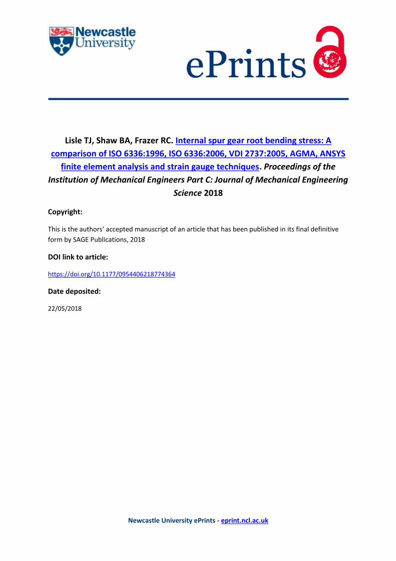
Newcastle University ePrints - eprint.ncl.ac.uk
Lisle TJ, Shaw BA, Frazer RC. Internal spur gear root bending stress: A
comparison of ISO 6336:1996, ISO 6336:2006, VDI 2737:2005, AGMA, ANSYS
finite element analysis and strain gauge techniques. Proceedings of the
Institution of Mechanical Engineers Part C: Journal of Mechanical Engineering
Science 2018
Copyright:
This is the authors’ accepted manuscript of an article that has been published in its final definitive
form by SAGE Publications, 2018
DOI link to article:
https://doi.org/10.1177/0954406218774364
Date deposited:
22/05/2018

Corresponding author:
Lisle TJ, Design Unit, Newcastle University, Newcastle upon Tyne. NE1 7RU, UK
Email: [email protected]
Internal spur gear root bending stress: A comparison of ISO
6336:1996, ISO 6336:2006, VDI 2737:2005, AGMA, ANSYS
finite element analysis and strain gauge techniques
TJ Lisle1, BA Shaw1 and RC Frazer1
1Design Unit, Newcastle University, UK
Abstract
The Association of German Engineers VDI 2737:2005 and the International
Organisation for Standardisation ISO 6336:2006 are universally accepted analytical
procedures for the analysis of internal gears. There is no official American Gear
Manufacturers Association (AGMA) standard for internal gear stress analysis due to
the validity of inscribing the Lewis parabola within internal concave profiles and the
resulting errors associated with the location of maximum root bending stress. This
research investigates the differences associated with using ISO 6336, VDI 2737 and an
unofficial AGMA method, all of which are compared against a potentially more
accurate numerical (ANSYS) method and strain gauge techniques.
Keywords
Internal gear; root bending stress; ANSYS finite element analysis; strain gauges; ISO
6336:2006; VDI2737:2005
Introduction
Since 1893, when Lewis1 proposed that the stresses in gear tooth roots could be
established by approximating their analysis as simple beams in bending, the complexity
of gear stress analysis has progressed considerably into its current guise, more of which
will be discussed later. Significant advances in gear research coincided with the advent
of what were novel stress analysis techniques such as photoelasticity2-7 and numerical
finite element methods8-17 which became common place in the early and late 1900’s
respectively, a summary of which has already been discussed in detail by Lisle et al.18
Arguably, the historic majority of this research concentrated on the analysis of external
gears, as opposed to internal gears, the stress analysis of which is now of equal
importance, especially with regards to the aerospace industry.
In 1996, the International Organisation for Standardisation released the first
version of ISO 633619 responsible for internal (and external) gear stress analysis,
assuming that the location of maximum internal tooth root bending stress coincided
with that of external gears, i.e. the 30 degree tangent point, as illustrated in Figure 1.
After its revision in 200620, this dramatically changed to 60 degrees raising concerns

over designs prior to 2006. The Association of German Engineers released VDI
2737:200521 which only analyses internal gears but augments ISO 6336:2006 by
accounting for rim deflections, radial tooth loads and centrifugal forces. The American
Gear Manufacturers Association do not have an official method for internal gear stress
analysis due to the method by which it determines the critical section. I.e. the location
of maximum root bending stress based on the inscribed Lewis parabola1 which as stated
by AGMA 908-B8922 is “inaccurate for short, stubby beams”. However, the AGMA
method has been independently adapted by Savage et al.23 based on the work of Lewis1
and Dolan and Broghamer3 albeit with uncertain results; this will be investigated and
designated the internal AGMA method, but it must be re-iterated that this is not an
official AGMA method: It is merely included here to highlight its pitfalls.
All methods of gear stress analysis produce different results, often for a number
of reasons, however this research aims to compare only the nominal stresses (those
without any load or stress increasing factors) calculated in accordance with ISO
6336:2006, ISO 6336:1996, VDI 2737:2005 and the AGMA method. Furthermore,
although VDI 2737:2005 has the ability to accommodate thin rim deflections, the work
herein is based on thick, un-deformable rims and as such that part of the VDI method
is not investigated; this does not detract from the quality and ability of the standard to
deal with thin rim deflections. Based on the success of the external root bending stress
validation18 the results will also be compared with numerical finite element analysis
(ANSYS) and experimental strain gauge techniques.
For reference, 1) ISO 6336:1996, ISO 6336:2006 and VDI 2737:2005 will be
designated as ISO 1996, ISO 2006 and VDI respectively, 2) ANSYS 12.1 was the
chosen FEA package, and 3) Dontyne Systems Gear Production Suite generated the
accurate 2D internal tooth profiles based on shaper cutter generation.
ISO, VDI and AGMA root bending stress
Internal root bending stresses established in accordance with ISO, VDI (step 1,
neglecting centrifugal forces) and the internal AGMA method, are established as
follows,
SF
n
t
ISOF YYmb
F
)( (1)
FS
n
tVDIF Y
mb
F
)( (2)
Y
K
b
F ft
AGMAF )( (3)
Equations (1) through to (3) are analogous to those used for external gears, where Ft, b
and mn are the tangential force, facewidth and normal module respectively. The height
and second moment of area of the tooth are accounted for via the form YF (ISO) and
geometry Y (AGMA) factors, whilst the root fillet radius is used to determine the stress
concentration factors YS (ISO) and Kf (AGMA). VDI differs slightly in its appearance
since it combines the stress concentration factor YSab together with the form factor for
bending YFa and compression YFad to produce the tip factor YFS. Indeed, the foundation

for all three of these stress analysis methods are identical, nevertheless discrepancies
arise due to a number of significant factors, namely,
The original release of ISO 1996 based the critical section on the 30o tangent
point, as per its external gear stress analysis procedures. ISO 2006 and VDI
both use the 60o tangent point whilst the AGMA method adopts the inscribed
Lewis parabola, for which Savage et al.23 present a method for its determination,
analogous to that provided by Dolan and Broghamer3 for external gears. Figure
1 provides a summary of the different methods.
Both VDI and AGMA resolve and superpose the normal tooth force (Fbt) into
its tangential (Ft) and radial (Fr) components, each of which creates a tensile and
compressive stress - in the tensile root - respectively.
Both ISO 1996 and ISO 2006 do not account for the radial component of tooth
loading.
Both ISO 6336:2006 and VDI 2737:2005 establish iteratively the root fillet
radius at the 60 degree tangent point based on the tool tip radius, albeit they can
produce different results.
Since there is no official AGMA standard for internal gears, there is no method
for establishing the AGMA root fillet radius required for the stress concentration
factor. For the purpose of this research, it was decided to establish the root fillet
radius in accordance with VDI, for use with AGMA.
ISO 1996 does not account for the true geometrical tooth shape. Instead it is
replaced with an equivalent straight sided “special rack”. The reader is directed
to ISO6336:199619 for further information.
ISO 2006, VDI and AGMA all take into account the actual tooth profile and
loaded angle (αFen).
ISO 1996 states that if the root fillet radius is unknown then ρF2 = 0.15mn. This
is a very basic assumption for such a critical parameter.
In summary, this report compares the root bending stress established using ISO 1996,
ISO 2006 and VDI with comparison against numerical FEA and experimental strain
gauge techniques. The unofficial internal AGMA method was included to highlight its
inappropriateness for internal gears.
Where possible, the geometrical values required to calculate the form and
geometry factors, such as the root chord length (sFn) and beam bending height (hFe)
were established directly from accurate 2D transverse tooth profiles. However, the
difficulty associated with physically measuring an ever changing trochoid root fillet
radius at a single point, led to this being determined analytically in accordance with the
respective standards.
Finally, because ISO 1996 replaces the actual tooth shape with an equivalent
“special rack”, the geometrical dimensions required for its stress analysis had to be
determined analytically in accordance with ISO 6336:1996 method B. Both Kawalek
and Wiktor11 and von Eiff et al.12 present a valuable insight into the errors associated
with the assumption of a special rack, as opposed to the actual tooth shape.

Figure 1. AGMA and the inscribed Lewis parabola (a), ISO 1996 and the 30o tangent
point (b) and ISO 2006 and VDI and the 60o tangent point (c)
ISO, VDI, AGMA, FEA and strain gauge comparison
Due to the difference in the predicted location of maximum root bending stress
established in accordance with each of the analytical methods, it was decided to validate
the theory against experimentally generated strain gauge results on an actual gear tooth,
in addition to FEA. To minimise the errors associated with the positional accuracy of
strain gauging normal module gear teeth in locations of high stress gradients, as has
been previously discussed18, a large module internal gear with a 4 meter reference
diameter was manufactured, the details of which are presented in Table 1 and illustrated
in Figure 2(a). Note that only partial adjacent gear teeth were manufactured, as has
previously been investigated so as not to introduce stress analysis errors18. The gear
tooth profile was wire cut from hardened (approximately 650Hv) and ground gauge
plate with a profile tolerance of ± 50μm. The gear tooth was statically clamped using
a bespoke jig - all faces of which had been precision ground - which was bolted to an
Instron loading machine, as illustrated in Figure 2(b). An independent compression
load cell, with valid UKAS force certification, was used to calibrate the Instron. A
loading anvil with a convex tip was necessary for loading the internal involute profile,
and was designed and manufactured such that it was longitudinally stiff but axially
(with regards to the gear tooth) flexible. This, together with the accurately ground jig
and tooth faces minimised non-uniform load distribution (kFβ) which was assumed to
be unity.
Table 1. The 50mm module internal gear specification
Face width (mm) b 10
Normal module (mm) mn 50
Pressure angle (deg) αn 20
Reference diameter (mm) d 4000
Tip diameter (mm) da 3900
Root diameter (mm) df 4125
Base diameter (mm) db 3758.771
Cutter tooth number z0 40
Tool tip radius (mm) ρfP 19.5
Cutter shift coefficient xo 0
(a) (b) (c)

Figure 2. The 50mm module wire spark eroded internal gear tooth (a) and jig (b)
Figure 3. FEA root bending stress profile going from tip to root
As one may expect, FEA of the gear tooth illustrated in Figure 2 merely provided yet
another location of maximum root bending stress which was neither at the 30 or 60
degree tangent point - or indeed the tangency of the inscribed parabola - but in fact lay
in-between both the 30o and 60o degree tangent points as illustrated in Figure 3. This
is not unusual as it has already been shown11-12 that the angle can vary between
approximately 35-60 degrees depending on the gear and tool geometry. The inscribed
Lewis parabola (point A) was situated on the flank which is clearly inaccurate. ISO
1996 and the 30 degree tangent point was furthest up the root (Point B) followed by
FEA (point C) and ISO 2006 and VDI (point D) i.e. the 60 degree tangent point.
Because of the large variation in the theoretical positions of critical bending, it
was decided to experimentally measure stress at each location using 0.79mm active
width constantan strain gauges, calibrated via a shunt resistor, as illustrated in Figures
4 (a) and (b). To compensate for temperature fluctuations and their resulting errors,
three additional unstressed gauges were used, per measurement position, thus
(a) (b)
completing the Wheatstone bridge circuit. With the application of a bridge voltage, an
amplified output voltage was supplied via and RPD transducer, which was subsequently
converted to stress.
Figure 4. Locations of maximum bending stress (a) and strain gauged positions (b)
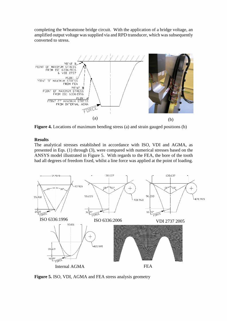
Results
The analytical stresses established in accordance with ISO, VDI and AGMA, as
presented in Eqs. (1) through (3), were compared with numerical stresses based on the
ANSYS model illustrated in Figure 5. With regards to the FEA, the bore of the tooth
had all degrees of freedom fixed, whilst a line force was applied at the point of loading.
Figure 5. ISO, VDI, AGMA and FEA stress analysis geometry
(b) (a)
FEA
ISO 6336:1996 ISO 6336:2006 VDI 2737 2005
Internal AGMA

The strain gauge root bending stresses were compared with numerical FEA using a
model of the full jig and anvil, as per the experimental set-up illustrated in Figure 6.
Note that the fundamental theory of the finite element method is omitted, as this well
documented process24 is not the intention of this research. However, details of
appropriate boundary conditions, mesh descretisation and contact conditions are
defined as follows.
Contact conditions between the tip of the convex anvil and concave involute
profile were dealt with using the augmented lagrange formulation with frictional flank
contact (μ=0.125) and program controlled normal contact stiffness. Load was applied
to the anvil in the vertical direction via its top face, with all degrees on freedom on the
base of the jig fixed. The influence of preload from the jig bolts were assumed
negligible and were therefore absent from the analysis. All remaining mating jig
surfaces were constrained using the ANSYS bonded contact. The difference between
the results established using the two different FEA models (Figures 5 and 6) were
minimal because the gear tooth, load and point of application were identical, however
no single FEA model would accurately represent both scenarios. All FEA gear models
were analysed as steel with a Young’s modulus of 207GPa in accordance with
Callister25 and were systematically refined using predominantly 20 node quadratic
hexahedral elements until stress had converged to within 1.0%. Each finite element
model was analysed at three different loads of 10kN, 15kN and 20kN, the results of
which are illustrated in Figures 7 and 8. The loads were chosen such that suitable levels
of bending stress were induced, without causing localised plastic deformation at the
anvil to involute interface due to high Hertzian contact stresses. Hence the requirement
for a hardened tooth profile as previously discussed.
Figure 6. Experimental (a) and numerical (b) models
(b) (a)

Figure 7. FEA, AGMA, ISO and VDI root bending stress results
Figure 8. FEA and strain gauge root bending stress results
Discussion and conclusions
From the results presented in Figure 7 it is clear that there is significant variation in the
location and magnitude of maximum root bending stress at each of the respective
standards (ISO, VDI and internal AGMA) whilst the results established from the strain
gauge experiments illustrated in Figure 8 established that FEA was the most accurate

method, with an approximate error of only 0.7%. As with any experimental technique
such as strain gauging, there exists a degree of measurement uncertainty which was
estimated based on the procedures outlined in26 to assess the errors associated with 1)
strain gauge positional accuracy, 2) UKAS Load cell uncertainty 3) accuracy of the
point of loading, 4) measurement resolution error, 5) shunt calibration accuracy and 6)
measurement repeatability. This resulted in an average expanded uncertainty (95% CI)
of approximately 1.7%.
Comparing only maximum stress values, ISO 1996 considerably overestimated
the root bending stress by 69.8% because it underestimated the root fillet radius and
root chord length as a consequence of assuming a special rack profile and the 30 degree
tangent point. VDI was the most accurate official analytical method, underestimating
stress by only 3.2% when compared to FEA, whilst ISO 2006 overestimated stress by
4.3%. Here, the difference between the stresses established in accordance with ISO
2006 and VDI, both of which had almost identical stress concentration factors, was
attributed to how the standards deal with the compressive component of stress. It is
perhaps understandable that by ignoring the radial component of loading, the tensile
fillet stress calculated in accordance with ISO 2006 is overestimated, when compared
to the VDI method.
The maximum bending stress established in accordance with the internal
AGMA method was within 1.8% of the FEA results, however this is coincidental
because 1) the Lewis parabola makes contact with the flank underestimating the root
chord length and beam bending height; thus compensating for one another and masking
the true errors of the method and 2) the stress concentration factor based on the work
of Dolan and Broghamer 3 is applied based on root geometry which is completely un-
associated with the location of the tangency of the inscribed parabola. Thus, although
the internal AGMA method provided the most accurate analytical result, it has no
justification, and should not be used, as per AGMA’s recommendations.
Although accurate, it can be argued that achieving FEA results requires far more
effort than pre-programmed analytical procedures such as ISO 2006 and VDI. It may
be argued further that the results established in accordance with both ISO 2006 and
VDI are quite reasonable, since other sources of error such as load distribution,
manufacturing errors, dynamic loads, application factors, planetary load sharing and
permissible material strength - though not strictly an error on stress - probably far
exceed the uncertainty surrounding the most current methods of internal gear stress
analysis.
Acknowledgements
This research was conducted by Design Unit at Newcastle University in collaboration
with Rolls Royce Plc. With regards to aerospace gears, internal gear stress analysis
procedures are of equal significance to their external counterpart and an accurate
understanding of the errors associated with each method is of the utmost importance.
Declaration of conflicting interests
The author(s) declared no potential conflicts of interest with respect to the research,
authorship, and/or publication of this article.
Funding
This work was conducted as part of a PhD research project, in connection with Rolls
Royce Plc, for which the author(s) received no grant funding, for the research,
authorship, and/or publication of this article.

References
1. Lewis W. Investigation of the strength of gear teeth. In: Proceedings of the Engineers
Club of Philadelphia 1892; pp16-23.
2. Timoshenko S and Baud RV, The strength of gear teeth. Mech Eng 1926; 48: 1105–
1109.
3. Dolan TJ and Broghamer EL. A photoelastic study of stresses in gear tooth fillets.
In: University of Illinois Engineering Experiment Station Bulletin Series No. 355, 1942.
4. Heywood RB. Tensile fillet stresses in loaded projections. Proc Inst Mech Eng 1948;
159: 384–398.
5. Jacobson MA. Bending stresses in spur gear teeth: proposed new design factors based
on a photo-elastic investigation. Proc Inst Mech Eng 1955; 169: 587–609.
6. Kelley BW and Pedersen R. The beam strength of modern gear-tooth design. SAE
Tech Paper 1958; 66: 137–157.
7. Allison IM and Hearn EJ. A new look at the bending strength of gear teeth. Exp Mech
1980; 20: 217–225.
8. Andrews JD. A finite element analysis of bending stresses induced in external and
internal involute spur gears. J Strain Anal Eng Des 1991; 26: 153–163.
9. Chabert G, Dang Tran T and Mathis R. An evaluation of stresses and deflection of
spur gear teeth under strain. ASME J Eng Ind 1974; 96: 85–93.
10. Tsay C-B. Helical gears with involute shaped teeth: geometry, computer simulation,
tooth contact analysis, and stress analysis. ASME J Mech Transm Autom Des 1988; 110:
482–491.
11. Kawalec A and Wiktor J. Tooth-root stress calculation of internal spur gears. Proc
Inst Mech Eng, Part B: J. Eng Manuf 2004; 218: 1153–1166.
12. von Eiff H, Hirschmann KH and Lechner G. Influence of gear tooth geometry on
tooth stress of external and internal gears. ASME J Mech Des 1990; 112: 575–583.
13. Kawalec A, Wiktor J and Ceglarek D. Comparative analysis of tooth-root strength
using ISO and AGMA standards in spur and helical gears with FEM-based verification.
ASME J Mech Des 2006; 128: 1141–1158.
14. Kawalec A and Wiktor J. Simulation of generation and tooth contact analysis of
helical gears with crowned flanks. Proc Inst Mech Eng, Part B: J. Eng Manuf 2008;
222: 1147–1160.
15. Wilcox L and Coleman W. Application of finite elements to the analysis of gear
tooth stresses. ASME J Eng Ind 1973; 95: 1139–1148.
16. Sfakiotakis VG, Vaitsis JP and Anifantis NK. Numerical simulation of conjugate
spur gear action. Comput Struct 2001; 79: 1153–1160.
17. Atanasovska I, Nikolić-Stanojević V, Dimitrijević D, et al. Finite element model
for stress analysis and nonlinear contact analysis of helical gears. Sci Tech Rev 2009;
64: 61–69.
18. Lisle TJ, Shaw BA and Frazer RC. External spur gear root bending stress: A
comparison of ISO 6336:2006, AGMA 2101-D04, ANSYS finite element analysis and
strain gauge techniques. Mech Mach Theory 2017; 111: 1-9.
19. ISO 6336:1996. Calculation and load capacity of spur and helical gears.
20. ISO 6336:2006. Calculation and load capacity of spur and helical gears.
21. VDI 2737:2005. Calculation of the load capacity of the tooth root in internal
toothings with influence of the gear rim.
22. AGMA 908-B89:1989. Geometry factors for determining the pitting resistance and
bending strength of spur, helical and herringbone gear teeth.

23. Savage M, Rubadeux KL and Coe HH. Bending strength model for internal spur
gear teeth. 31st Joint Propulsion Conference and Exhibit. San Diego, CA, United States,
July 10th-12th, 1995.
24. NAFEMS. A Finite Element Primer. Glasgow: NAFEMS, 2003.
25. Callister WD. Fundamentals of Material Science and Engineering: An Interactive
E-text. 5th ed. USA: John Wiley & Sons, Inc, 2001.
26. M3003. The Expression of Uncertainty and Confidence in Measurement. 2nd ed.
United Kingdom Accreditation Service.
Copyright © 2022 FDOKUMEN