
Isolation and molecular characterization of Newcastle disease viruses from raptors
Upload
khangminh22Category
view
0download
0
;
NEWCASTLE UNIVERSITY LIBRARY
087 11813 3
7-1-\ es 1 s L3 cl_
ROCK BOLT REINFORCEMENT SYSTEMS
FOR COAL MINE ROADWAYS
By
David Michael Tully, M.Sc.
Thesis submitted to the University of Newcastle upon Tyne
for the Degree of Doctor of Philosophy
November 1987

"En hvatki er missagt er i fraebum kessum, ka erskylt at hafa bat heldr, er sannara reynist."
An Thorgilsson
Islendingabokc. 1130 AD

AFFIRMATION
The work submitted in this thesis is my own, and has not been previously
submitted for any other degree. The following publications have been
presented based on this research
Mosley, J.T.B. & Tully, D.M. 1986. Roof bolting in friable strata atRufford Colliery. Colliery Guardian, V.234, p.305-307.
Tully, D.M. 1987. The application of scale model studies in the designof rock bolting systems for mine roadways. Proc. 28th US Symp. onRock Mechanics, University of Arizona, Tucson, p.781-788.

ii
ABSTRACT
The utilisation of rock bolting for the support of British coal mine
roadways can improve roadway strata conditions and, by permitting a
reduction in the density, cross-section or total elimination of steel
standing support, can produce considerable savings in roadway support
costs.
This study reviews worldwide experiences in the use of rock bolt
reinforcement techniques to enhance the stability of coal mine roadways.
Details of methods of geotechnical design data acquisition and
assessment are given as well as a critical study of various empirical,
analytical and observational methods of tunnel support design. The use
of scale model studies is shown to be particularly effective for the
design of rock bolt support systems for coal mine roadways.
With reference to numerous case studies, descriptions are given of rock
bolt systems available and their suitability to specific mine roadway
conditions is discussed. Installation procedures and equipment are also
reviewed.
It is the author's intention that this study should be used as the basis
for further detailed investigation of specific aspects of rock bolt
support systems. A number of recommendations are made as to the fields
in which further research should be undertaken.

iii
CONTENTS
PageAFFIRMATIONABSTRACTCONTENTSLIST OF FIGURES viiLIST OF TABLES
CHAPTER 1 : INTRODUCTION 11.1 The techniques and history of rock bolting 11.2 Mechanisms of rock bolting 2
1.2.1 Background 2
1.2.2 Suspension from competent strata 2
1.2.3 Beam building 2
1.2.4 Keying of blocks 31.3 Maintaining rock mass integrity 4
CHAPTER 2 : GEOTECHNICAL DESIGN DATA ACQUISITION AND ASSESSMENT 82.1 Background 82.2 Physical properties of the rock mass 92.3 Anchorage characteristics of specific horizons 102.4 Parting planes 122.5 Lateral thickness variations 132.6 Localised variations in lithology 13
2.6.1 Palaeochannels 132.6.2 Concretions 152.6.3 Clay veins 18
2.7 Fracture planes 192.7.1 Faults 192.7.2 Slickenslides 192.7.3 Joints 222.7.4 Cleat 23
2.8 Weatherability of strata 232.9 Groundwater 242.10 Ground stresses 25
CHAPTER 3 : EMPIRICAL DESIGN METHODS 303.1 Background 303.2 Rock quality designation 303.3 Stability index 323.4 The Q-system 333.5 The Geomechanics Classification 383.6 CERCHAR empirical design method 523.7 US Corps of Engineers guidlines 553.8 German suitability criteria 55
CHAPTER 4 : ANALYTICAL METHODS OF DESIGN 604.1 Background 604.2 Analysis of the suspension effect 604.3 Analysis of the beam building effect 614.4 Analysis of the stability of key blocks and arching action 63
4.4.1 Key block bolting 63
4.4.2 Analysis of yield zones 64
4.4.3 Theory of jointed bodies 66
4.4.4 Voussoir rock arch 68
4.4.5 Rock mass confinement approach 69
4.4.6 Reinforced rock units 73
iv
4.5 Numerical modelling 75
4.6 Physical modelling 764.6.1 Design of specific sites 764.6.2 Qualitative assessment of rock bolting parameters 84
CHAPTER 5 : DESIGN THROUGH IN SITU MEASUREMENT DURING EXCAVATION 1005.1 Background 1005.2 Rock-support interaction 1005.3 New Austrian Tunnelling Method 1005.4 Roadway instrumentation 104
5.4.1 Background 1045.4.2 Convergence measurement 1045.4.3 Borehole extensometers 1055.4.4 Alarm systems 1095.4.5 Borescopes 1115.4.6 Rock bolt load measuring techniques 1115.4.7 Standing support load measuring techniques 117
CHAPTER 6 : PRELIMINARY INVESTIGATIONS FOR ROCK BOLTING SYSTEMSIN THE DEEP HARD/PIPER SEAM IN NOTTINGHAMSHIRE 118
6.1 Background 118
6.2 Geotechnical evaluation of roof strata 121
6.3 Directional stability 129
6.4 Interaction effects 130
6.5 Extraction effects 133
6.6 Support system design 1396.6.1 Position of bolt installation 1396.6.2 Roof bolt length 1396.6.3 Reducing support density 1406.6.4 Ribside spelling 1436.6.5 Empirical and analytical design methods 143
CHAPTER 7 : POINT ANCHORED ROCK BOLTS 1447.1 Background 1447.2 Slot and wedge bolts 145
7.2.1 Installation 1457.2.2 Slot and wedge bolts as a gateroad support 145
7.3 Expansion shell bolts 1477.3.1 Installation 1477.3.2 Expansion shell bolts as a gateroad support 1517.3.3 Expansion shell bolts as a support in room and
pillar mining 1517.4 Grouted point anchored bolts 153
7.4.1 Installation 1537.4.2 Resin point anchored bolts as a gateroad support 156
7.5 Point anchored grouted expansion shell bolts 158
CHAPTER 8 : FULL COLUMN ROOF BOLTING WITH ORGANIC GROUTS 1608.1 Materials and installation 160
8.1.1 Polyester resin capsules 1608.1.2 Bolt parameters 1628.1.3 Bolt hole parameters 1628.1.4 Installation procedure 1638.1.5 Checking installation 1668.1.6 Pre-tensioned systems 167
8.2 Reinforcement of the face entry 1688.3 Dual roof bolt - steel standing support systems for
gateroads serving advancing faces 1708.4 Rock bolting as the primary support for gateroads of
advancing faces 171

8.5 Dual roof bolt - steel standing support systems forgateroads serving retreating faces 1718.5.1 Post-development rock bolt reinforcement 1718.5.2 Roof bolt performance in differing lithologies 1748.5.3 Roof bolting in delaminating strata 1768.5.4 Roof bolting in friable strata 1798.5.5 Roof bolting to reduce steel work 188
8.6 Rock bolt reinforcement as the primary support for retreatdrivages 1908.6.1 Worldwide experience 1908.6.2 Scale model feasibility study 1938.6.3 Scale model feasibility study for a new prospect 200
8.7 Roof bolt support for partial extraction operations 207
CHAPTER 9 : FULL COLUMN BOLTING WITH INORGANIC GROUTS 2099.1 Cement grouts 2099.2 Gypsum grouts 211
9.2.1 Background 2119.2.2 Packaged water plaster capsules 2119.2.3 Dry hemihydrate with microencapsulated water 2119.2.4 Inhibited gypsum slurry 2149.2.5 Pellet injection device 2149.2.6 Slurry injection machines 2159.2.7 Performance of gypsum anchored rock bolts 217
CHAPTER 10 : ROCK BOLT REINFORCEMENT OF ROADWAY RIBSIDES 220
CHAPTER 11 : ROCK BOLT REINFORCEMENT OF GATEROAD FLOORS 22311.1 Background 22311.2 Mechanisms of floor bolt reinforcement systems 22311.3 Installation position 22811.4 Floor bolt reinforcement patterns 22811.5 Extended floor bolting 230 •11.6 Failure mode of bolted floors 23211.7 Effect of bolting on roof deformation 23211.8 Floor drilling 232
CHAPTER 12 : TRUSS BOLTING TECHNIQUES 23612.1 Background 23612.2 Scale model studies 23812.3 Limits of behaviour 23812.4 Optimum design of roof truss installations 24112.5 Monitoring 24712.6 Application of sling type trusses 24712.7 Application of single bar angle bolt trusses: tensioned at
blocks 24812.8 Application of single bar angle bolt trusses: wedge-box
tensioned 25212.9 Application of double bar angle bolt trusses 25312.10 Recent developments 255
CHAPTER 13 : EXTENDED GROUND SUPPORT 25713.1 Background 25713.2 Axial loading characteristics of cable bolts 25713.3 Cable bolt applications 26113.4 Swellex long rock bolt 26113.5 Extended ground support design 263

viCHAPTER 14 : ALTERNATIVE ROCK BOLTING SYSTEMS 2-6414.1 Background 26414.2 Yielding rock bolts 26414.3 Split Set rock bolts 26614.4 . Swellex rock bolts 26914.5 Alternative rock bolt systems developed by the US Bureau
of Mines 271
CHAPTER 15 : ROCK BOLTING ACCESSORIES AND EQUIPMENT 27215.1 End plates, straps and roof bars 27215.2 Lining materials 27315.3 Drilling and installation equipment 273
CHAPTER 16 : GENERAL COMMENTS, CONCLUSIONS AND RECOMMENDATIONSFOR FURTHER RESEARCH 278
ACKNOWLEDGEMENTS 284
REFERENCES 285
APPENDIX 1 : MODEL STRATA CONFIGURATIONS 312
APPENDIX 2 : SUPPORT CONFIGURATIONS FOR MODELLED ROADWAYS 322
vi i
LIST OF FIGURES
Figure Title Rage
1.1 Mechanisms of rock bolting 4
1.2 Assumed strain distributions for axial and transverseshear loadings 6
2.1 Pull test apparatus 11
2.2 Influence of bond length on anchor strength 11
2.3 Channels at various levels relative to coal seams 14
2.4 Use of angled bolts to support shale strata at channelmargins 16.
2.5 Kettlebottom detaching along weak bedding plane 17
2.6 Common support techniques for kettlebottoms in US mines 17
2.7 Proposed method for support of fractured strata invicinity of a clay vein 20
2.8 Clay vein associated fracture and fault plane boltingdiagrams 20
2.9 Wedge-shape cantilever liable to failure because of athrust fault 21
2.10 Angled bolting of slickenslides 21
2.11 Variation of virgin vertical and horizontal stresseswith depth 27
2.12 Stress distribution around a longwall face 27
2.13 Directional stability effect of maximum lateral stresscomponent 29
3.1 Proposed use of RQD for choice of rock support system 34
3.2 Relationship between exposure factor and roadway width 34
3.3 Support categories based on rock mass quality andequivalent dimensions 34
3.4 Relationship between stand-up time of an unsupportedunderground excavation and Geomechanics Classification 47
3.5 Support mechanisms for hard rock mines based on theGeomechanics Classification 47
3.6 Corrective factors to calculate convergence in relationto the type of roadway 58
3.7 Determination of the beneficial effect of bolting inarch shaped roadways 58
4.1 Nomogram for rock bolting calculations in layered roof 62
4.2 Effect of roadway support on yield zone 65
4.3 Rock bolt pattern design based on the theory of jointedbodies 67
4.4 Concept of ground arching and the rock arch 70
4.5 Development of uniform compression zone by use oftensioned bolts 70
4.6 Effective increase in allowable rock stress withincreased confinement 74
4.7 Concept of reinforced rock units 74
4.8 British Coal HQTD roadway model rig 77
4.9 Laboratory strength of rock versus sand content ofmodel rock 79
4.10 Physical model of a mine roadway 80
4.11 Simulated roof bolts in a model roadway 82
4.12 Effect of applied pressure ratio on support performance 85
4.13 Deformation of modelled roadways under various stressconditions 88
4.14 Support performance under different applied pressureratios 90
4.15 Comparison of roof bolt patterns 94
4.16 Comparison of individual bolt pattern components 96
viii
4.17 Comparison of roof bolt lengths 97
4.18 Comparison of the effect of strata strength on supportperformance 99
5.1 Load-deformation curve for rock mass and support system 101
5.2 Construction of the Arlberg Tunnel 103
5.3 Convergence trends 106
5.4 Roadway monitoring station (roof) 110
6.1 Sherwood/Mansfield Colliery Deep Hard/Piper Seam 119
6.2 Deep Hard East No.2 ISM 3000 Head 120
6.3 Position of parting planes above Deep Hard/Piper Seam 122
6.4 Parting plane along erosion surface 123
6.5 Geotechnical borehole logs 125
6.6 Borehole core from above 127A's tail gate/face endline junction 128
6.7 Model simulation of roof fall at Sherwood Colliery 131
6.8 Water inflow - 2nd West Main Road 132
6.9 Measurements from Sherwood Colliery monitoring stations 134
6.10 Ribside stress distribution around 125's loader gate 137
6.11 202's face entry 138
6.12 Mansfield Colliery scale models 141
6.13 Sherwood Colliery scale models 142
7.1 Three types of point anchored rock bolt 146
7.2 Mechanical expansion anchors 148
7.3 Piper seam section and slot and wedge bolting pattern 149
7.4 High Hazels seam section and expansion shell boltingpattern 149
7.5 Support plan: Foidel Creek Mine 154
7.6 Grouted point anchors 155
7.7 Installation of the Peabody-McDowell bolt 157
7.8 Point anchored grouted expansion shell bolts 159
8.1 Effect of bolt diameter on resin mixing characteristics 164
8.2 Full column resin grouted bolt installation procedure 165
8.3 Resin grouted roof bolts 169
8.4 Rock bolt reinforcement of N31's face entry, EppletonColliery 172
8.5 Original bolting design for 12's return gate, BaddesleyColliery 172
8.6 Rock bolt reinforcement of an advanced heading, LaHouvre Colliery 172
8.7 Post development reinforcement of retreat gateroads 173
8.8 Section of strata in the vicinity of the main conveyordrift, Snowdown Colliery 177
8.9 Snowdown Colliery scale models 178
8.10 Closure recorded at a monitoring station in 2DR's tailgate, Riccall Colliery 180
8.11 Section of strata in the vicinity of 206's panel,Rufford Colliery 181
8.12 Original steel standing support for 206's main gate,Rufford Colliery 183
8.13 Re-designed steel standing support for 206's main gate,Rufford Colliery 183
8.14 Re-design of 206's main gate at Rufford Colliery 184
8,15 Convergence measurements recorded in 206's main gate,Rufford Colliery 186
8.16 Rufford Colliery scale models 187
8.17 Section of strata in the vicinity of 88's panel,Welbeck Colliery 189
8.18 Models illustrating the closure of 88's proposeddevelopment roadway at Welbeck Colliery 191
8.19 Welbeck Colliery scale models 192
8.20 A typical rock bolted roadway at Niederberg Colliery 194

ix
8.21 Strata sections in vicinity of M25's panel, PenalltaColliery 195
8.22 Rose diagram showing joint orientations in vicinity ofM25's panel, Penallta Colliery 198
8.23 Penallta Colliery scale models 1998.24 Margam Prospect: Gellideg Seam structure plan 2018.25 Strata sections in vicinity of the Gellideg Seam,
Margam Prospect 2038.26 Model roadway equivalent dimensions and roof bolt
pattern, Margam Prospect 2058.27 Margam model roadway - cover load 2069.1 Cement grout insertion techniques 2109.2 Water tube capsules 2139.3 Gypsum grout with microencapsulated water 2139.4 Slurry injection: twin-screw extruder system 2169.5 Slurry injection: in-the-hole mix system 21810.1 Probable mode of rib spall according to drivage
direction 22210.2 Fibreglass rock bolts 22211.1 Examples of floor bolting patterns used in British
coal mines 22911.2 Floor bolted scale model studies 23111.3 Floor bolting: scale model comparisons 23311.4 Method for the drilling and injection of bolt holes
in mine floors 23511.5 Extended floor bolting at Rossenray Colliery 23512.1 Truss bolt systems 23712.2 Scale model of sling type truss bolt system 23912.3 Comparison of simulated sling type truss bolts with
full column anchored roof bolts 24012.4 Force diagrams and relative chord tensions of trusses 24212.5 Assumed pressure distribution for a fully active sling
truss 24312.6 Statics of a roof truss 24312.7 Approximate boundary stress concentrations in a
rectangular opening 24612.8 Optimum slope for angle bolts based on bending strain
energy 24612.9 Convergence and support loading recorded in 103's main
gate, Thoresby Colliery 24912.10 Pattin truss installed at Jane Mine 25112.11 Jennmar truss installed at Jane Mine 25112.12 Truss wedge tensioner 25412.13 Double bar angle bolt truss 25412.14 Intersection truss 25612.15 Continuous entry truss 25613.1 Typical cable bolts 25813.2 Cable bolt pull tests 26014.1 Some concepts of yielding rock bolts 26514.2 Load bearing and deformation behaviour of a kombi bolt 26514.3 Split Set bolt 26814.4 Swellex bolt 26815.1 Comparison of simulated thin steel straps with steel
girders bolted to the roof 27415.2 Examples of rock bolt drilling equipment 276

x
LIST OT TABLES
Table Title Page
3.1 Rock classification for preliminary assessment of rockbolt support requirements 31
3.2 Values of stress concentration factor (K) 333.3 Values of rock failure factor (b) 333.4 Support recommendation based on rock stability index 353.5 Classification of individual parameters used in the
Q-system 363.6 Values for ESR 383.7 Suggested support for Q-system categories 393.8 Geomechanics Classification of jointed rock masses 443.9 Excavation and support recommendations for rock tunnels
based on the Geomechanics Classification 483.10 Support recommendations for Indian coal mine roadways
based on the Geomechanics Classification 493.11 Support recommendations for US coal mine roadways based
on the Geomechanics Classification 503.12 Matrix for choosing the main parameters of a rock
bolting pattern 543.13 Typical empirical design recommendations 564.1 Formulae to calculate load on support system 724.2 Model scale factors 766.1 Roof bolt parameters derived from empirical & analytical
design methods for Deep Hard/Piper seam workings 14311.1 Floor bolting trials with mechanical anchored bolts 22411.2 Floor bolting trials with free flowing resin grouted
bolts 22511.3 Floor bolting trials with capsule resin anchored bolts 22613.1 Details of cable bolts used in metalliferrous mining 262

1
CHAPTER 1
INTRODUCTION
1.1 The Techniques And History Of Rock Bolting
The development of rock bolt reinforcement techniques began in the
nineteenth century with the use of simple wooden dowels in slate
quarries and tin mines. During the 1930s the St Joseph Lead Company
successfully applied rock bolting techniques in their mines in the
United States.
Following the 1939-1945 war rock bolting became widespread in US coal
mining operations which initiated interest in the techniques by British
mining engineers. By 1959 over 100 km of underground roadways were
supported by rock bolts alone in British collieries (Adcock 1959).
These bolts were point anchored by a mechanical device at the top of the
hole and tensioned. Several roof failures occurred and rock bolting was
condemned as being an unreliable means of support in British coal mines.
During the 1960s and 1970s improvements in the mechanical shell unit and
the development of resinous materials as an anchorage medium led to a
gradual increase in the use of rock bolting for supplementary support of
British coal mine roadways. This was paralleled by the utilisation of
rock bolting as the sole means of support in the majority of other
underground mining operations throughout the world.
In 1984 considerable interest in the potential of rock bolts as a
primary and supplementary means of support in British coal mines was
again initiated. The type of bolt most widely used in the British rock
bolting trials of the 1980s is the full column anchored bolt; the
annulus between the steel bolt and the hole wall is grouted with resin
throughout its length. There are a number of other types of rock bolt
reinforcement systems available which are suited to specific mining
situations; these include truss bolts, yielding bolts, pre-tensioned
full column anchored bolts, full column mechanical bolts (e.g. Swellex
and Split Set), inorganically grouted bolts and cable bolts.
2
1.2 Mechanisms Of Rock Bolting
1.2.1 Background
Immediately following the excavation of an underground opening, stress
redistribution occurs so that vertical compressive stresses existing
within the rock mass are transferred to the strata adjacent to the
excavation. Tensile and shear forces develop in the de-stressed area
above and below the excavation due to the bending of strata layers as
they delaminate. The resultant deformation of the rock mass leads to
closure of the opening.
Rock bolt reinforcement is capable of strengthening the rock mass to
sustain greater stresses and increase the integrity of the roof strata.
Possible mechanisms of rock bolt action in coal measures strata detailed
in the following sub-sections have been identified from in situ
observations and model studies.
1.2.2 Suspension From Competent Strata
The mechanism of suspension considers the rock bolt as a suspension
device transferring the mass of a finite volume of weak rock from a
layer of overlying competent strata (Figure 1.1a). The length of rock
bolt should be adequate to traverse through weaker rock zones and
provide the necessary anchoring length in the stronger strata for the
transfer of load.
Point anchored bolts transfer the load at the bottom of the bolt to the
competent rock at the anchor zone at the top of the hole. Full column
anchored bolts provide a greater shear surface for the transmission of
the load from the rock to the bolt and vice versa. If there is
differential movement along the bolt, then there is differential
suspension. The load at one point could possibly be reacted just above
the loading point, or carried in the bolt until a competent layer or
horizon is encountered.
1.2.3 Beam Building
Mine roadways, being much longer than they are wide, are often modelled
using elementary beam equations. The use of such techniques for the
analysis of bolted roofs is well established (Panek 1956a, 1956b, 1956c,
1964; Obert and Duvall 1967).
The basic concept of this reinforcement mechanism is to bind thin layers
of rock together so that they behave as one thick layer (Figure 1.1b).

3Thus, through beam building, the mechanism provides a means to carry the
horizontal shear produced by bending. This can be accomplished by
preventing sliding of the rock layers over each other, that is,
producing shear resistance by frictional forces on the bedding planes or
shear resistance of the bolts themselves.
Tensioned rock bolts (either point or full column anchored) provide some
compressive force to increase the frictional resistance of the bedding
planes. Full column anchored bolts (tensioned or untensioned) are
capable of resisting horizontal slip by shear resistance.
1.2.4 Keying Of Blocks
The rock surrounding a coal mine roadway can be intersected by various
discontinuity systems with different orientations forming discrete rock
blocks around the periphery of the opening. The eventual movement or
slip of the blocks along the discontinuities can be prevented or reduced
with rock bolts which cross these planes,. thus keying the blocks
together (Figure 1.1c). The keying action can lead to the formation of
competent rock arches across a roadway.
In a similar manner to the beam building mechanism, tensioned bolts rely
on the development of frictional interfaces and a locking phenomena,
whereas full column anchored bolts resist slip along discontinuities by
shear resistance.
1.3 Maintaining Rock Mass Integrity
Gale (1986) states that "the primary aim of reinforcement design is to
enhance confinement and restraint of axial and shear displacements
occurring in the rock as it is exposed at the face in order to maintain
the structural strength of the roof strata to maximise the self
supportive capability to bridge or arch across an opening, and to
restrict the height and lateral ektent of failure in the roof".
Section 1.2 summarises some of the benefits of fully grouted rock bolts,
which are capable of developing both axial and shear restraint. The
axial stiffness of fully grouted bolts is nominally 10 to 20 times
greater than for mechanical point anchored bolts (McCoy et al 1971;
Barnes 1971; Franklin and Woodfield 1971; Fells 1974; Haas et al 1978).
Lateral and/or axial movement within the rock mass causes load to be
transferred to the bolt via shear stresses in the grout. Additional
movement increases the load on the bolt and reduces the rate of movement

N
4
r----- _
-_ .
-..
•,
//
a. Suspension from competent strata.
b. Beam building.
W gi gf'. .n
11M,.. 1 2fitS4,
..M.-...n=1.n..-I: rar...7.
,
......
.;•/;// ,/ ,
CXALALL.$0 ;
/ COALAlL.AR
7 1 /#/I A
// e
///,2/
/ ///, .
c. Keying of blocks
Figure 1.1 Mechanisms of rock bolting.

5in the mine rock. This process takes place through transference of
developed load to stable rock (Serbousek and Signer 1987).
Radcliffe and Stateham (1980) have observed that a single fully grouted
rock bolt can be in both tension and compression at different points
along its length.
Under axial load induced by strata separation, a uniform strain
distribution will be created either side of a fracture (Figure 1.2a).
The length of influence along the bolt being a function of the load
magnitude and bolt/rock properties. Creep of resin bolts has been found
to increase the load transfer distance with time, particularly in softer
rocks and coal (Kwitowski and Wade 1980).
When subjected to transverse shear the bolt will be flexed above and
below the shear interface, causing flexural (bending) strain to occur in
the bolt core fibres located away from the neutral axis. The form of
flexural distribution and the length of influence will be functions of
the magnitude of transverse shear activity (the differential lateral
displacement) and the bolt/rock properties. The load transfer length
under transverse shear loading has been found to be much less than under
axial loading (Kwitowski and Wade 1980). Tensile (positive) flexural
strain will be at a maximum at a point farthest from the neutral axis
and, diametrically opposite, a compressive (negative) flexural strain of
equal magnitude will occur. Axial force can develop in a bolt as a
secondary effect of transverse shear activity. This axial force might
be caused by the bolt core stretching near the shear interface or by
shear friction (Farmer 1975). The resulting strain distribution will be
the algebraic sum of the flexural and axial strain distributions (Figure
1.2b).
Axial loading and transverse shear occurring simultaneously will produce
the strain distribution depicted in Figure 1.2c.
The mechanical interlock between the bolt and the grout, and the grout
and the rock are the most important parameters in developing the
reinforcing strength of fully grouted roof bolts (Gerdeen et al 1977;
Serbousek and Signer 1985). Under loading, mechanical interlock will
cause shear forces to be transferred from one media to another until the
maximum shear strength is reached. At that point, the weakest material
will fail and then friction will control the load transfer.

S-1
(1/
(i)
CO
S-1
"cfa
cci
co
0
-1=1
4-1Cl)
e--•
Cl) 0
COco
'17)
(1)
g
cn
3
6
/5
s g Cl/
_a(r)-
vN.
,
8 Ui(.3 Cr1
• co
Ui O./(I)
$.4
00
GE-4

7
The mode of failure therefore depends on the characteristics of the
reinforcement system and the material properties of the individual
elements. Four types of failure are commonly recognised:
(i) failure of the rock mass;
(ii) failure at the grout/rock interface;
(iii) failure at the grout/bolt interface;
(iv) failure of the bolt.

8
CHAPTER 2
GEOTECHNICAL DESIGN DATA ACQUISITION AND ASSESSMENT
2.1 Background
A primary aim of the initial stages of the design programme of an under-
ground opening is to gain an accurate prediction of strata stability and
support requirements. There are no satisfactory quantitative solutions
currently available, although approximate solutions can be obtained
based on practical experience. The assessment of strata stability and
support requirements is an evolutionary process that should begin in the
preliminary planning stages and continue with development and mining.
The design of a rock bolting system for a mine roadway must be based on
criteria concerning the nature of the strata, the stress field in the
rock mass and limitations imposed by the mining method and equipment
available. The first stage of the, design process is to carry out a
geotechnical assessment of the site. This should identify geological
structures and other features affecting roadway stability as well as
establish parameters for use in empirical and analytical design methods.
Information gathered can also be used for the planning and interpret-
ation of a roadway monitoring programme.
Preliminary information may be obtained from a study of available
archives. Sources include published and unpublished geological maps,
reports, memoirs etc; logs of excavations and boreholes in close
proximity to the proposed roadway and reports on projects in similar
geological conditions/mining environments. The compilation of a data
base of rock bolting sites in British coal mines is currently being
undertaken at British Coal HQTD; this should be a valuable source of
preliminary information in the future.
Further geotechnical data for engineering design purposes can be
acquired from a combination of regional geological and in-mine geotech-
nical mapping, borehole core logging and laboratory sample testing.
Procedures should be undertaken to detect geological anomalies and
potentially hazardous ground conditions prior to roadway development.
Mapping of these and other features can provide an effective means of
locating areas where strata control design adjustments need to be made.
The number and types of maps necessary will vary depending on the nature

9of the site. Typical maps and sections of a proposed roadway may
include:
(i) Isopach maps of the type and thickness of the immediate roof and
floor strata.
(ii) Isopach maps of potential parting planes.
(iii) Maps and sections showing the position of adjacent, superjacent
and subjacent mining.
(iv) Palaeoenvironmental maps.
(v) Structural maps.
(vi) Maps showing areas of roof falls and excessive roadway closure in
adjacent mine workings.
Plotting the data on separate maps of a similar scale will permit super-
positioning of these maps to locate areas where a number of potential
hazards overlap.
The following sections discuss some of the important features to be
identified and evaluated during a geotechnical assessment of a proposed
mine roadway.
2.2 Physical Properties Of The Rock Mass
Data concerning the physical properties of rock can be obtained from
laboratory testing of samples taken from the site or borehole cores.
Commonly determined parameters are mechanical properties such as
uniaxial and triaxial compressive strengths, tensile strength, shear
strength and internal angle of friction; as well as elastic constants,
i.e. Poisson's ratio at a specific strain and the modulus of elasticity.
The mechanical properties describe the strength of the rock material,
how well the rock will stand and at what level of stress failure will
commence. Knowledge of shear and tensile strengths are particularly
useful because typical roof failures in a rectangular mine roadway
consist of tensile failure at the centre of the opening and shear
failures on either side at the intersection of roof line and ribline.
The elastic constants describe how the rock material will react to
changes in stress in terms of strain and subsequent deformation of the
excavation. Details of testing techniques have been described by
Szlavin (1971), Davis (1978, 1981), Knight (1979) and ISRM (1981).
Rock strength can be estimated on site with a cone indenter (NCB 1977)
or by qualitative judgement using the scheme adopted by Piteau (1970).

10
Effective rock bolt reinforcement is generally obtainable in rocks with
uniaxial compressive strengths greater than 40 MPa and good triaxial
characteristics, e.g. a triaxial stress factor (k) greater than 3.5.
Weaker rocks, especially those with a uniaxial compressive strength less
than 25 MPa and poor triaxial characteristics, e.g. k less than 3.0, may
not be able to provide anchorage locations. Due to a larger anchorage
length, full column anchored bolts tend to be more effective at
supporting weak strata than point anchored bolts. With most mechanical
bolts, there is a problem with tension bleed off in soft rock resulting
from anchor slippage (Section 7.3.1).
Straps are usually essential with weak roof rock to prevent rock
fragments falling from between bolts, thus destroying the reinforced
beam effect produced by the bolting system.
Identification of a competent bed above the immediate roof could have a
significant influence on the choice of bolt length, so that the
mechanism of suspension can be achieved.
2.3 Anchorage Characteristics Of Specific Horizons
Some optimum rock bolt parameters can be determined from pull testing of
bolts with a short anchorage length. A typical pull test consists of a
force being applied to a bolt via a hydraulic jack with displacement
being measured by an extensometer (Figure 2.1). For analysis the load
is plotted against displacement. Details of pull test procedures are
given by ISRM (1981, 1985).
Franklin and Woodfield (1971) determined design data for a particular
resin grout. Figure 2.2 shows the bond length required to achieve a
certain pull strength in five different rock types. It is evident that
weaker rocks require a greater bond length to achieve the same overall
strength. Pull testing by Dunham (1973) concluded that resin bonded
lengths of 25 or more diameters appear to be long enough to develop
sufficient load to break steel rebar rock bolts (for moderately strong
rock).
Pull testing of short grout encapsulation lengths (significantly less
than 25 times the bolt diameter) will give data on the bonding
capability of specific target horizons in the rock mass. The inform-
ation can then be used for determination of optimum bolt lengths.
Similar tests may be performed for mechanical point anchored bolts or

Hand pump
Ir
( : 5kr:Ira
:
Bolt UTS
Yield point
30In
—sr
20
80 10
11
Anchorage
Rock bolt
Hydraulic jacket
Extensometer
Figure 2.1 Pull test apparatus
40
60 in.1
1.5m
Bond length
Figure 2.2 Influence of bond length on anchor strength(after Franklin & Woodfield 1971)
200.5

12
Swellex bolts. (Restricting the anchor length of a Swellex is achieved
by the use of a steel tube - Section 14.4).
The bonding capability of specific horizons can also be determined from
external or single point internal load measuring devices (Section 5.4.6)
fixed to point anchored bolts. The bolt is installed at the head end
during roadway drivage. The mean axial bolt load that develops is
plotted against face advance. Gale and Fabjanczyk (1985, 1986) consider
this approach to be more satisfactory than pull testing as the perform-
ance of an anchor in a highly stressed and deforming zone is measured,
rather than a static block of effectively destressed rock outbye of the
face.
2.4 Parting Planes
The stiffness of a roof stratum determines its ability to support itself
and overlying strata. Stiffness is proportional to thickness so that
thinly laminated roof rock (with bedding planes parallel to the roadway
roof) will tend to separate into thin slabs that are weak and will break
easily, whereas thick, massive beds are frequently able to form stable
roofs. Delamination of strata can result from deposits of micaceous
material along the bedding planes
grain size, carbonized debris
induration and erosion surfaces.
strata and maintain a roof beam.
, mineralogical variations, changes in
and non-deposition, causing local
Roof bolts will help to stiffen the
The choice of roof bolt length should be influenced by the position of
major parting planes; for instance it would be undesirable to have the
top of the bolts directly below such a plane as this could result in
collapse of the bolted slab en masse.
Borehole extensometers are a useful tool for gathering information
regarding the position of strata displacements and the height and
geometry of any weakened rock above the roadway. If installed in an
excavation in the vicinity of a proposed roadway they can give relevant
design data.
An extensometer consists of one or more reference anchors positioned at
various depths within a borehole. The relative displacements of strata
are measured (either mechanically or electrically) as a change in the
distance between anchors and the borehole collar. There are many types
of extensometers and anchorage points, details are given in Section
13
5.4.3. Their installation, use and data interpretation are covered by
the ISRM (1981) suggested methods.
The position of fracture zones can be identified from shallow slope
sections on a plot of anchor distance from excavation surface against
anchor displacement. Strains generated in the strata are then deter-
mined by calculating the percentage change in length between individual
anchors. Points of high strain indicate major parting planes, rock
integrity changes and sections where increased loading would be antici-
pated in full column anchored rock bolts. Rock bolts of sufficient
length should be used to extend across dominant rock failure zones (Gale
1986).
Borescope observations assist in the interpretation of results from
extensometer installations (Section 5.4.5). The mode of roof dilation
and specific intervals and lithologies where fracturing occurs can be
determined from the inspection of a borehole adjacent to an extenso-
meter.
2.5 Lateral Thickness Variations
Thinning or thickening of the immediate roof strata will effect the
position of significant competent beds or parting planes above the roof
line. It is therefore important to map relevant strata thicknesses so
that bolting parameters can be altered where necessary.
2.6 Localised Variations In Lithology
2.6.1 Palaeochannels
Palaeochannels are remnants of ancient stream channels that have cut
into underlying sediments. Clarke (1963) has made a comprehensive study
of roof rolls, washouts, swilleys and other channel related structures
found in the Durham coalfield. Depending on the nature of the channel,
a variety of lithologies can result (Figure 2.3). Some of these
structures and other features associated with a sandstone filled
palaeochannel can produce adverse roof conditions.
If a roof sandstone is an aquifer, moisture may be present in roof bolt
holes (McCabe and Pascoe 1978). Water dripping from a bolt hole can
give an indication of the presence of a channel as the heading advances
towards it.
Slickenslides, compactional faults and slumping can result from

\ S SiZN.° tu
.;.:2 . r-. N71,
Soy 10 m
S sandstone
Z : siltstone
M : mudstone
seat-earth
: weak roofA breccia
./ • fault/ •
: coal
• fracture
14
Figure 2.3 Channels at various levels relative to coal seams (after NCB 1984).

15
differential compaction between the coal or immediate mudstone roof and
an overlying sandstone channel (Hylbert 1978).
Geotechnical/palaeoenvironmental mapping can establish the relationships
between potential hazards and channels so that an operator will know in
advance of mining when drivages are nearing a channel (Ledvina 1986).
Where this is not possible, the presence of channels may be inferred in
areas where drill core data indicate that thick, lenticular, crossbedded
sandstone occurs close to the top of the coal seam. Concretions, clay
veins, and thinning and thickening of a coal seam also suggest that a
channel is near.
Moebs (1984) recommends the use of angled bolts which anchor into the
competent channel filling as a means of supporting mudstone/shale
channel margins (Figure 2.4). In severe cases posts and cross bars
should be used.
2.6.2 Concretions
The immediate roof of many coal seams contains masses of mineral matter
known as concretions. They are usually ellipsoidal in shape and range
in size from a few millimetres to several metres in diameter. Concret-
ions that can cause hazardous roof conditions include siderite nodules
and coal balls. They are usually accompanied by slickenslided surfaces
and are frequently composed of a denser material than the surrounding
rock. This facilitates detachment from the roadway roof without
warning.
Kettlebottoms are another type of concretion that can produce minor roof
falls. They are preserved casts of ancient tree stumps which occur in
coal measures strata in Great Britain, the United States, Poland and
elsewhere (Raistrict and Marshall 1939; Williamson 1967). Kettlebottom
mold and cast surfaces are highly slickenslided. A layer of coalified
bark remnants, which varies in thickness from a thin film to 20 mm thick
usually separates the kettlebottom mold from its cast. Cohesion between
the mold and cast is weak and, when undermined, it is only tensile
strength along bedding planes that prevents the structures from
detaching. Figure 2.5 illustrates the mode of kettlebottom failure.
Siderite nodules and coal balls tend to be widely distributed in certain
roof strata. However, kettlebottoms and similar structures are often
small local features of erratic occurrance, which cannot be detected by

-_
_
-- -
o1
0
16
- - --
--
4 Ft
IM
Scale
Figure 2.4 Use of angled bolts to support shale strata at channel margins.Dashed line outlines rock not fully supported by verticalbolting (after Moebs 1984).

Bond between kettlebottom=_- and overlying rock —
____ Coal ring between=-7— cast and mold —
--Bedding plane-.=within cost
=Slickensided=-mold surface —
7
11 1 1; 11Slickensided
I cast surface
4416-\CI
\
I / Gravity 1
_Separation along a=weak bedding plane-
-
Mine roofDal ring
I 1 I
Mine entry
I LiiL
'I \I \'
I
SECTIONAL PROFILE
0 5
Scale, ftWood or steel
—77-4header
-
/Wood plank o
steel strap
1/
Figure 2.5 Kettlebottom detaching along weak bedding plane(after Chase & Sames 1983).
REFLECTED ROOF PLAN
Figure 2.6 Common support techniques for kettlebottoms in US mines(after Chase & Sames 1983).

18
core drilling.
Where possible small and relatively thin concretions should be barred
down from the roof before they fall. Supporting the thicker concretions
will prevent the formation of roof voids and minimise the area of roof
adversely affected by moist air (Section 2.8). Clusters of small
concretions can be supported by bolted straps and/or wire mesh. Larger
concretions such as kettlebottoms can be supported by roof bolts. Some
techniques used in the USA are depicted in Figure 2.6. Methods A and B
can subject the bolter operator to risk as vibration during drilling
could be sufficient to dislodge the concretion. In addition, method A
assumes that the bolt length available is longer than the structure,
this may not always be the case. Method C is more suited to support of
concretions less than 1 m in diameter whereas method D should be used
for concretions greater than 1 m in diameter.
The practice of leaving a thin layer of top coal is not advisable where
kettlebottoms are likely because the coal may not have sufficient
strength to support the structure.
2.6.3 Clay Veins
Clay veins are probably the result of clay-filled fissures formed in the
seam and surrounding strata before the coal was totally compacted.
Slickenslides then develop as a result of differential compaction.
These can be orientated either randomly or in parallel sets and
contribute to roof instability when the seam is mined. Clay veins range
from a few millimetres to two metres or so wide and may persist for a
hundred metres in length. Due to their narrow width, clay veins are
rarely detected by exploratory drilling. However, they generally have
linear to curvilinear strikes and once located can therefore be
projected for varying distances in advance of mining (Chase 1985).
Preferred orientations can only be determined if clay veins are mapped
and analysed.
Ellenberger (1979) recommends the use of full column grouted rock bolts
to support the fractured strata in the vicinity of a clay vein. The
bolts should be angled towards the centre of the structure so that the
slickenslides are bound together and slippage along the planes is
prevented (Figure 2.7).

192.7 Fracture Planes
2.7.1 Faults
Faults constitute a structural weakness and wherever they are present
rock blocks can detach from the mine roof. Underground excavations can
be affected by a variety of fault parameters such as type, inclination,
trend, throw and/or horizontal displacement, gouge thickness, vertical
extent and the presence of joints, slickenslides and/or anomalous
stresses.
A case study carried out in New South Wales, Australia by Shepherd and
Fisher (1978) found that normal oblique and strike-slip faults were much
more deleterious to drivages than normal dip-slip faults.
The presence of faults in an area of development can be predicted from
the study of stratigraphical sections, geological mapping and extra-
polation along strike or in the case of multiple seam working, along dip
from other areas of the mine.
When a fault zone is encountered in a roadway it is generally necessary
to use steel standing supports, although the stability of a fault zone
may be enhanced by the correct use of rock bolting techniques. Figure
2.8 shows how extended bolting and angled bolting can improve faulted
roof conditions. Jeremic (1980) has demonstrated the danger of mining
beneath a low angle fault in the immediate roof (Figure 2.9).
2.7.2 Slickenslides
Predominantly a feature . of argillaceous rocks, slickenslides (or
"slips") are smooth, polished and sometimes striated surfaces resulting
from movement of rock on either side of a plane. Slickenslides in coal
mine roof strata are generally curved in a convex fashion towards the
coal bed. They have little or no cohesive strength. Slickenslides are
found throughout the British coalfields but are particularly common in
South Wales and Kent. Where they occur in large concentrations, core
drilling may be able to detect these features in advance of mining.
They are known to be associated with faults, palaeochannels and clay
veins (Sections 2.7.1, 2.6.1 and 2.6.3).
Zones with slickenslides of limited extent can be supported by rock
bolts with straps and/or wire mesh. Large slickenslides are often
extremely hazardous but may be supported by a dense pattern of angled
bolts (Figure 2.10).

*PA -,04*-11..Ivii%,
Drawslate Rider coal
Cobl
Roof
v
0-. P11101
H Seam emit by triNK) Iona, root bait and mat
Beam WO ay .ung tangoed =I oar and mat
2U
Full column resin bolt inclined 30° fromvertical toward center of clay vein
O 110 20 Feetl
11
i
O 3 6 MetersScale
Figure 2.7 Proposed method for support of fractured strata in the vicinityof a clay vein (after Ellenberger 1979).
Solgto na y wemA ssociated frocn.
cc Wu.
:zn • never-- -.4.‘00010 • 000111
Oct.
,nelfiknyo onnng
Figure 2.8 Clay vein associated fracture and fault plane boltingdiagrams (after Chase 1985).

Roof bolts
••••n
CI aystone— — –
-
—Slickenside
Ang =—bolt
Coal-bed
Entry
—
r_
_
Bolt— —
n
21
Thrust
Mine roadway
Dangerous
of advance direction of advance
Figure 2.9 Wedge—shape cantilever liable to failure because of athrust fault (after Jeremic 1980).
____„ Safer direction
---
-- Underclay
_•••••••.. ••••- •-•-• ••••-• ,••••-• o•- •-•• •
0 4 Ft
0 I MScale
Figure 2.10 Angled bolting of slickenslides (after Moebs 1984).

22
2.7.3 Joints
The influence of joints on roof stability depends upon:
(a) The nature or type of fracturing.
(b) The length, continuity, direction and attitude of the joint surfaces
and their relative orientations to mine openings.
(c) The density or spacing and convergency of joints.
(d) The interaction with other factors of geological weakness.
Methods of describing and measuring joint parameters have been described
in detail by the Geological Society Engineering Group (1977) and ISRM
(1981). Coates et al (1977) demonstrated how inclined core drilling
through near-horizontal beds and sub-vertical joints can give an
excellent indication of joint frequency, orientation and filling.
Inaccuracies can occur in joint spacing measurements made from borehole
core due to rock breakage during the drilling operation and removal from
the core barrel. It is possible to measure the orientation of joint
sets from borehole cores providing care is taken to orientate the core.
Artificial orientation devices operated from the core barrel are
available, such as the Craelius core orientator. To obtain joint
orientation data from heavily fractured rock masses, a core recovery
method known as the integral sampling method can be employed (Rocha and
Barroso 1971). Prior to recovery, the core is reinforced with a grouted
bar whose azimuth is known from positioning rods. The reinforced bar is
coaxially overcored with a large diameter coring crown.
If possible in situ measurements should be taken in existing nearby
excavations along scanlines (Priest and Hudson 1976, 1981). The use of
orthorhombic sets of scanlines (Anderson et al 1977) will help prevent
preferential sampling of joints orientated normal to the scanline
(Terzaghi 1965). McCrae and Cook (1985) suggest a combination of
scanline mapping and sketching of all the exposed rock will result in a
more thorough survey and enable the identification of possible areas of
instability. Ewan et al (1983) have reported on the reproducibility of
joint spacing and orientation measurements taken on scanlines. They
concluded that the variation in the number of joints recorded by
different observers can be as high as a factor of four, but with a mean
of about two; and for measurement of orientation an average maximum
error of +10 0 for dip direction and +5 0 for dip angle was recorded.
23
2.7.4 Cleat
Cleat refers to conjugate joint systems in coal that are composed of
closely-spaced, sub-vertical fractures. The best developed set is known
as the primary cleat. There is usually a secondary and occasionally a
tertiary cleat system. There are a number of theories concerning the
formation of cleat sets. McCullock et al (1974) believe that they are
the result of tectonic activity (as are joints), whereas Ting (1977)
suggests that they are caused by dehydration during the coalification
process.
Measurement of cleat orientations from borehole core is particularly
difficult due to the friable nature of-coal. However, measurement of
underground exposures is relatively simple (Section 2.7.3).
The direction of drivage relative to the cleat orientation is often an
important factor in determining in-seam roadway stability. Roadways
driven parallel to the direction of the primary cleat are particularly
susceptible to ribside spalling of the coal, which can increase the
roadway width above the critical dimension so that roof and floor
instability may ensue.
Ribside bolting patterns can be designed to intersect these planes of
weakness and enhance stability, especially when used in conjunction with
a liner (Chapter 10).
Coal face spalling may occur at the head end in roadways driven
perpendicular to the primary cleat and if top coal is left in the roof
it is often more liable to collapse.
2.8 Weatherability Of Strata
Argillaceous roadway roofs are often subjected to delayed deformation
due to deterioration as a result of weathering in the mine environment.
This problem has been recognised for many years in the United States and
considerable research has been carried out by the US Bureau of Mines on
the causes and effects of roof deterioration as well as methods of
prevention (Hartman and Greenwald 1941; Fish et al 1944; Bobeck and
Clifton 1973; Haynes 1975; Aughenbaugh and Bruzewski 1976; Stateham and
Radcliffe 1978; Radcliffe and Stateham 1978; Cummings et al 1981;
Cummings et al 1983). A study of the breakdown of British coal measure
rocks has been undertaken by Taylor and Spears (1970).

24
Chemical degradation of a mudstone roof caused by humid mine air will
result in a decrease in strata strength. In addition, physical
weathering due to expansion resulting from moisture absorption will also
cause deterioration, especially when subjected to alternating wet and
dry spells.
Slake durability tests give an assessment of weatherability (ISRM 1981;
Davis 1981). Dejean and Raffoux (1980a) recommend evaluating the rock
permeability to give an estimation of its liability to deterioration.
Rock with a high permeability should be further analysed by full
pressure 'water filtration. . A high concentration of calcium and
potassium ions recovered from the first filtrate indicates a partic-
ularly susceptible rock.
The presence of pyrite should be noted as crystals readily decompose by
hydration and oxidation in mine air; the resulting sulphuric acid reacts
with argillaceous minerals. In addition, the dilative recrystallization
force from sulphate mineral formation will micro-fracture the
surrounding strata.
Full column bonding of rock bolts will prevent strata deterioration at
the bolt hole wall. There are a number of methods for protecting the
roof surface. Leaving a thin layer of top coal to buffer the roof is
one technique; alternatively sealants such as sprayed concrete, tar or
polymeric sealants may be applied. Another method favoured in the USA
is the incorporation of conditioning chambers into the mine layout for
air tempering (Sames 1985).
2.9 Groundwater
High ground water in-flow rates can have a serious effect on the
stability of an underground opening. Water will tend to reduce inter-
facial friction on parting planes and joint surfaces, as well as erode
and weather the strata.
Longwall mining induced fractures can disturb roof strata up to 30 to 50
times the mining height. If an aquifer is located in the fractured
zone, water may drain down into the workings. Geological mapping will
assist in the identification of aquifers likely to influence a roadway.
The interstitial pressure is measured using piezometers installed in the
strata and the permeability of a rock mass is measured by-means of a
permeametric test.

25
The presence of excessive water reduces the anchoring strengths of
inorganic grouts (Section 9.27 and Hunter 1986) and will limit the use
of point anchored and friction bolts to a temporary support applications
due to bolt corrosion. If sprayed concrete is applied it is important
to prevent pressure build up behind the lining.
2.10 Ground Stresses
Analysis of the in situ stress field is an important consideration in
the design of a roadway rock bolt reinforcement system. Prior to the
excavation of an opening, states of stress exist in the rock mass which
are functions of gravitational and tectonic forces, thermal stresses,
gas pressures, and material and rheologic properties of the strata. In
the British Coal Measures, thermal stress and gas pressures are regarded
as having a negligible effect.
The gravitational vertical stress is directly related to the depth of
overburden. Assuming the average unit weight of strata above coal
measures is in the order of 0.025 MN m -3 , the vertical component of
stress (av) can be taken as approximately:
av — . 0.025H MPa
where H = depth of overburden (m)
A study by Brown and Hoek (1978) of actual in situ stress measurements
taken at many locations throughout the world (mainly in hard rock) has
shown the magnitude of horizontal stress to be much more variable than
the vertical component (Figure 2.11). The range of the horizontal
component of stress (an) was found to be:
an — 0.5 to 4.0 x uv
Virtually no measurement data on in situ stress fields has been obtained
for British coal mine's. Wilson (1980) considers that in these relat-
ively soft rocks it is probable that creep over geological time will
have caused equalization of horizontal and vertical pressures. Many
observations of deformation and failure around British coal mine
roadways support this hypothesis, however; it is now becoming apparent
that anisotropic stress fields may exist in some collieries (Golder
Associates 1986; Gale 1987).
In soft rock at depth, the induced stress magnitudes frequently exceed
the rock strength, this results in rock failure and the subsequent
development of a yield zone.

26
Geomorphological features such as streams, valleys, and mountains as
well as geological features such as sedimentary structures (e.g. paleo-
channels) and igneous bodies can affect principal stress magnitudes and
directions. High stresses should also be expected in the vicinity of
major faults.
Obert (1966) suggests that the measured stress condition near an under-
ground opening may differ from the theoretical prediction due to stress
relief in the fractured rock around the opening which shifts the point
of high stress further into the rock mass. There are many techniques
and devices available for the measurement of ground stresses. Some of
these are described by Bauer (1985) and ISRM (1987). Useful information
concerning the nature of the stress field surrounding a roadway can be
obtained by means of observations (e.g. mapping stress induced
fractures) or deformation measurements.
Just as 'the excavation of a single opening redefines the state of stress
in a rock mass, the excavation of adjacent, superjacent or subjacent
openings will also result in further redistribution of stresses.
Figure 2.12 illustrates the stress distribution around a longwall face.
At some distance from the excavation there is a gradual increase in the
vertical stress above cover load, reaching a maximum a short distance
from the boundary of the excavation. There is a destressed region on
the excavation side of this peak. The front abutment zone generally
extends 30 m in front of the face; a significant increase occurs 15 to
5 m from the face line, with a peak 1 to 3 m ahead of the face. The
magnitude of the front abutment can vary considerably depending on the
nature and structural characteristics of the surrounding strata, the
distance from effective support and the extraction height. It is
commonly in excess of four times the cover load.
Determination of adequate pillar sizes is of particular importance in
roadway design. Formulae derived by Wilson (1980) can give some
estimate of the stress distribution in a coal ribside adjacent to a
longwall face extraction. The calculations are based on the "stress
balance" principle, whereby the stress reduction over the longwall waste
must be compensated for by an equivalent stress increase over the
ribside and vice-versa.
Interactions between subjacent and superjacent workings tend to be

Front stratapressureabutment,ace
Y
Corner peakpressure ---clue tointeraction otabut mentS
— Flank stratapressure abutment
XI
rth-establishment Of strata""-looding in waste area
X2
1-3m
AZ
X2
0-3-0.4h0%surt ace subside=1 Cover load pressure (p)
SectionYY
welnoninNr114141-7---An Coved waste
SectionXIX,
SectionX 2 X 2
27
s'ress4
'APO;v 0C-
H v2 3
N
• n-on
X.X.
X
N.
NN
N.
NN'
c' : 0 025 H (MPG)1000
tz'ac3
ce.1)"c'
N.I
/-C
a.no b- Ja 2000 -
a)
I
/
/
/I
I /
100n„0) c,
9-3000
I/
Figure 2.11 Variation of virgin vertical and horizontal stresses with depth(after Brown & Hoek 1978).
—... w•—,.1 3-10m or 0 . 013h 1 1
i L_ 1;
1 1-- 1_ 7 J— ' 71 - 7 - 7._- 1 : _, _ _, _.
.../........"7 ) , I \ 1 n - ,
60m is usual limit Of discernible Weals clu• tosingle panel working P1 • depth
Figure 2.12 Stress distribution around a longwall face.

28
difficult to predict owing to their complex nature. Redistribution of
stress between pillars results in high vertical stress concentrations
under pillar edges which are particularly prevalent within 50 m of the
extraction.
Anisotropic stress environments, either natural or the result of mining
activities, will considerably influence the occurrence and mode of rock
failure.
Under high lateral stresses, massive roof and floor rock will fail with
low angle shearing whereas laminated strata will fail forming an
inverted V-type fracture pattern (Lawrence 1972; Parker 1973; Univer-
sity of Nottingham 1985). Field observations (Blevins and Dopp 1985)
and three dimensional stress analysis using the boundary integral
equation method (Gale and Blackwood 1987) have shown that in stress
fields with dominant lateral stress components, the roadway drivage
direction has a considerable effect upon the type and geometry of
failure in the surrounding rock mass. In the United States, regionally
high horizontal stresses are considered to be one of the causes of
cutter roof failures (Moebs and Stateham 1986; Hill 1986; Su and Peng
1987). A cutter is a steeply dipping fracture that initiates at the
ribline and propagates upwards into the roof rock. The likelihood of
rock shear failure increases as the roadway axis tends towards 90 0 to
the maximium lateral stress component (Figure 2.13). Thus it is very
important to consider the magnitude and orientation of in situ stress
fields during mine planning.
Under high vertical stress concentrations, vertical or sub-vertical
tensile cracks tend to develop above the roadway ribline without the
formation of an inverted V-type failure in laminated strata. In extreme
cases roof collapse can occur en masse.
Rock bolt reinforcement of roadways subjected to anisotropic stress
fields is discussed in Section 4.6.2.

Roadway could exhibitguttering and cut offalong this side of theexcavation
Induced fractureshading outbye
Tension cracks
ShearsDirection of major stress
Inducedfractureshading outbye
Di rec t/ onof
advance
29
Roadway in good condition
Figure 2.13 Directional stability effect of maximum lateral stress
component.


CO lrs trb IN IN 0
6I I 1 I 1 ir0 0. .0 .0 0. .0-0 6 c d 6 6
CIJ
S..'
Gr.
$-•
0
0.
En
O ..0
C/)
Cfl
Ca
5-1Ca
E•
Cll 000'
O 01.6-1
O F)
-r-1
•
Cf)
Ca ce
0:•
•
•n E70'
to ;O 1';
▪
;O
r:L. :9 47,
• 7 t 130' Cr
E o: to 2
.9
1
0
E. ,E -8-
2 t. 2 e. .. .. ..
-=,.. _. .4 ,.. It ...i.' .1.'
... . r ,0. .- v
C-
7-' 1-1: .2 2 2 .2, -';7 .3; c
.,;-'' .= . -0 .; .3 c_ v c_ ,.„, c_
L' z.: 2 F, C EC. .
E .:-. F. ,i-1 7
a a a-5.--: ,• -- ).. . :-. . ›. -o >.. -7... >. -o
't0. 0.. „ E . E . . . c ps 0
n••• E E .., E . E ,'. E '1 E '',
7, .: 1, V Q 7 0 :8 tr, -5 er., -5 . -5
,E '-z -= 2 ,bi 2 ,,, . .., I= n:sc 52
5 5 8 .1, 8 .1., 8 E '.: 0 E c.7 .7., , ..c 0 ...., '.: .. e a e
t'.. t_, 6 7, -5 7 , ..• i-, c 1,.. ^ '..,, P<, r: t..• .-I
L.' ." .1 .f. 5,E c % :6- 2.- -
7, 72 g 25 `c-
'.k• 7 7
z`alz
. .
. .s• :,., 1,.2 t,-;iv 4
I i
E -a E
i -gbc c
a et,
".* :.:. sE5 t 8(..; 2 2 6 ...
c0 0 in C
o i-- in - u,L I I 8 ...,CC
r.-'c,.,-, 01
In ('10. 07; c -8 , a °ic 0 8 a i c g . cy..: CC 0 CL Is. cC g ct > g
7 T. -0t .0 z-, >-. o-7,E
. E ifi.-
g T>2. g, ... .0t.I In
7 i'! C r, T1 2 -05 ,..-.. y.k-, 5 -a 5
-0 -.z c v -0 -LI P, t.' ),....Z. Ir1 11 il Li .. 1 >

32
arise from different drilling teams. Problems can occur with the
misinterpretation of drilling induced fractures and accidental damage.
In addition, fracture orientation with respect to drilling must be
considered. For example, the RQD obtained from a borehole drilled
perpendicular to fractures regularly spaced at 85 mm (±14 mm) intervals
would be 0%. Whereas if the hole was drilled at an inclination of 45% a
fracture spacing of 113 mm would be recorded giving a RQD of 100%.
Hansagi (1965 and 1974) developed a method for determining the degree of
fissuration of rock by analysis of core fragmentation. Five classes of
rock strength were introduced based on uniaxial compressive strength
determined from rock samples and the fissuration factor (c or Kiruna
factor) determined from analysis of borehole core. For particular
classes of rock strength Hansagi (1974) recommends the use of rock
bolting with different parameters, pointing out that a roadway 5 in wide
and 3.6 m high with a roof rock compressive strength greater than 35 MPa
will not require support. This method was developed for the Kiruna mine
in Sweden and is clearly not directly applicable to British coal mining
conditions in its present form.
3.3 Stability Index
Sikora and Kidybinskt (1977) have developed a method for obtaining a
value of effective strength of mine roof rock using a hydraulic borehole
penetrometer (Stears 1965). A rock stability index is then obtained
which Sikora and Kidybinski applied to the design of coal mine roadway
support in Upper Silesia. The average effective strength (Ref) of the
roof is calculated from penetration resistance profiles taken from an
86 mm diameter borehole according to the formula
Ref = W. Psr
where Ref — effective rock strength (T/m2)Psr — average value of critical penetration pressure (from
pressure gauge)w — penetrometer coefficient
The rock stability index (Sg) is determined from the equation
Ss —Ref/H.k.a.b
where H — depthk — stress concentration factor, obtained from in situ
measurement or approximated from Table 3.2b — rock failure factor, approximated from Table 3.3a — exposure factor depending on roadway size, approximated from
Figure 3.2
33
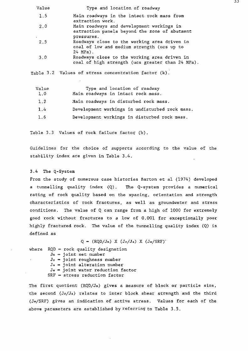
Value Type and location of roadway
1.5 Main roadways in the intact rock mass fromextraction work.
2.0 Main roadways and development workings inextraction panels beyond the zone of abutmentpressures.
2.5 Roadways close to the working area driven incoal of low and medium strength (ucs up to24 MPa).
3.0 Roadways close to the working area driven incoal of high strength (ucs greater than 24 MPa).
Table 3.2 Values of stress concentration factor (k).
Value Type and location of roadway
1.0 Main roadways in intact rock mass.
1.2 Main roadways in disturbed rock mass.
1.4 Development workings in undisturbed rock mass.
1.6 Development workings in disturbed rock mass.
Table 3.3 Values of rock failure factor (b).
Guidelines for the choice of supports according to the value of the
stability index are given in Table 3.4.
3.4 The Q-System
From the study of numerous case histories Barton et al (1974) developed
a tunnelling quality index (Q). The Q-system provides a numerical
rating of rock quality based on the spacing, orientation and strength
characteristics of rock fractures, as well as groundwater and stress
conditions. The value of Q can range from a high of 1000 for extremely
good rock without fractures to a low of 0.001 for exceptionally poor
highly fractured rock. The value of the tunnelling quality index (Q) is
defined as
Q (RQD/Jn) X (Jr/Ja) X (Jw/SRF)
where RQD — rock quality designationJn = joint set numberJr = joint roughness numberJa joint alteration numberJw — joint water reduction factorSRF — stress reduction factor
The first quotient (RQD/Jn) gives a measure of block or particle size,
the second (Jr/Ja) relates to inter block shear strength and the third
(Jw/SRF) gives an indication of active stress. Values for each of the
above parameters are established by referring to Table 3.5.

_ -
5. 1 00
40 50 6010 30
E2I am- El1n11•nn ••nn •••••n•nnnnnn =wes
IJECIPTOONAL IT
P0011
I XTIIIINIELTP0011 POOR 00•••
3113.
US
EI,
2
—z
5
=—
x
a.-
z
x
3.
3
34
C.7 NO SUPPORT
OR -0GAL BOLT I NG
TUNNEL WIDTH - FEET
Figure 3.1 Proposed use of RQD for choice(after Merritt 1972).
of rock support system
1
2 3 4 5 6Width of roadway, m
Figure 3.2 Relationship between the exposure factor (a) androadway width (after Sikora & Kidybinski 1977).
MMEMINNINIMMIHMMingliMmINIMMONIM=00...--ammissasie n im.......---- "'"11110105.1.0110
irlIMINIMMININIIMMUI1111=111001"*--1.1119111111111111111"." 111111
IOW Pill°
1=2.."COO 041111111
n1111111M11111111 M•IUM_11E11111R111111fin
==.2::••••• 1n .= MOOS.,
=MEMOMMIMOO.
—40:3111 EM=MEN 11 EM•OMNI
1 EMMMINise IMMEIN•usenMENION011
MIUM•964
11111116111111111111111111111111111111111
umwommos•• Inmilmo••••1=11•11•1111301
11•10•6611n IMMIN•11118
.•••nnn ••••nn•=2:17r.....10 n11=0•1111111n11MMIESS1101
-ailMIMMIMIO111111n 11M•1111111111NIM••111111
1•1111 ••• 11411, a • To• •••
JwROCK MASS QUALFFN Q =
RQD Jr x x
jn ja
Figure 3.3 Support categories based on rock mass quality andequivalent dimensions (after Barton et al 1974).

r00 .•-•
u •8.• .0 .7 •O 7,/L'OCII,1:18?146r;t o -
we. tic; tt6.7200 0 3 4• 0 n C.
8
•
. . 2. 7 °22-22 ' 22 n .72.
-a/ .1 AITO OWL.C C 00 •
7. :1 ° 8.I. 4.0 0 IL 0-024•-• • a.. • •
.4 L'.•••
▪
11.1 .C 1.1 VI 8..t •n• 20..0 D CI 0 4
eve,.1•• ••• • 0O a0..
GI• u
a • •
CC-CO19.2"R
44 CC,a01-
O•1J 0 nil a. al
2_t=(J4)046
-5.9-287, • •r 2c
a'CC
• C 7S 7. 7. E -
- . -0.40 •-• c - - 6 m
„;. te.t ,qr...ruCar
7CCa.00.7rcvccr L = -
Ca-.C.
InJ C z
'C')E CL74. N
C.
••••C •-• oo- .C , L 2.
- -
a a. -0 c C a 27 c 00- 7- 7 .2 3 7 ,; -7 3 7.;
7: car CA g"Ea-.c•ACr•-•
.0 vo n
- E E 2 '7'L o.LC
-3 ; ° 7 74.- 3v C. 7.1 •-• L
..1 0,11. 7 .-1 11-0 LC= .0 L C C C
6.6>. CE- .CO0CC.- tn
4140 OCOCC
•-•I.Z C .cLn
117, •n 2 L .r. 1. a..
• C...C.C4 4.7 N..
- - 2
r. . . 0401.
00 -0O30c4.u_.....10.0-•-•7
• II 4. ...000.0 /AO
-
1. 1
35
C . - onto,-
Cc -i., tE.cc
rU'.:P.C7e
or c-oCE
CC°0°.ar
1
2 g
2
t•CO.-C
ccv“
•-•
cuu
tC,0
CC-CC z C. C;8 - 8 •).
L a..
.- C•04J---
0 0 e m
c-°
c t° .
6.0C 7
3 cL OCOCLCM-0 E.
nC
• I-. a_
0u
1. A
,
A
.3 0
•-•
Cr. ; 0 -8.5 .9.c0
0 0
CD
0
C.,
t
u
• •-•C••Z,'Z' .2 3 ... E. 2
C CaJaC .J C:7 t-' - ' 1.-.. 2 8 7 •
. 0 0 - 0 - EIn •• NC't.1..'C't11
0
...Calr y 1.941- n n...1...70... U n ....(71,.....A40 C41>40 01-000.4041 aw , ... 00 41... 111•X • 0 W4CTO• WC4W.0•CTIO. E - -....• la . C .-IX014•6. ..,4-..A.-sa.. n CUL.CCL.mul.. ...).-.20 L., 00CO a.. u ... ..0 .:
Narat... -'IDIO0 VW-U- 6,0...C1C aa, 1.. aAei0.4140 01..41040 ...taa 4145:.0 vo. 1.. 0 - •••• • 80.CMUC ...0JavalC 1A-001.0- Ca ........ 1 ma a, a. 004. M ..0.0 .., .. OL..-..
•••a0 0 0,-.0-0 c.0-“Jc 4..0 00.,1.0m 0 E0
W C- C...041D OC.. - ov -, c Cu.., ...41,--404140744 0..2.60 CC.... -.MA 0.6C,, -0 -..1..00•0000.•6. 11.n ••-.5 .-11e1.1 • .04 Owl ...O., V In
G.t.:1›.....0..Z..;>.0 -7-27.2"-2,9, r,. """0-."-=a a • VI Iv. .. wElell-7 .0- .U..#"T l'i 0 -. -5 0O -2. 11 :: ..' .i.• a. rfaL. c a) yal....11JOr ..1 a .0 .... C C .... ...2 a..0 C >. ga--Z jt C .0..11 al ) E 2 ° -7•••,7 L-car a. ,C L CO LI .7 ... gr, 4
•C •Ct C0 4 1.. ,Ce... v. 0 0 .0 0 ) 0 M 4 0- .0 L. -. .-4 ... .0 • • 0
44:4. .... .... Ca 111041a01.0 El EOM ...7 -na:-.:..tt-6":2,-.:::„:;-...... .. u 0._ .....-...- la.O•ala.
w ° S.. r. 8-..f. -7 8.. -.: .. -0 . ;,- ° -,..-- 000 .-•.VC....D0.6-.Comua •l lilL. • .0 "407 l- Cr%-.0O 3- • OC.0 tu .... 0 n1.12114.41.-% 2 .1.. ... • -13 7....• Cur ..CMCWWL.,-.-....^L,.40 CC C 113C7 L. -..au0d. s, -. O. O. , 0 a nAla y -n - ou. %ac ... • .. - ... ,.. .0 (3 2 • • D a c .c a.. *A 0 4041 .0 0 .. -..• L.0. Ei ..-. • I-. .1c • a.. .0 in.-. h Cl
.., •-.
•
CC,. 4.,...01.•
• of D.4.8 DC 0.4,4.
7NYCL..7L+0B•V•al 9
7. 407 C C.0.04706/ C•n•• u•Ma
8 gang-u,--.00. 4JIAIJD a•••Cau0ma y.1101.
COa.08.•
la
▪
• 0 -.00.0 C
0. Ii0 •-• 0 NI Le
a

36
Description Value Notes
1. Rock Quality Designation (RQD)
A. Very poor 0— 25 (1) Where RQD is reported or measured as 410, (includingB. Poor 25— 50 0) a nominal value of 10 is used CO evaluate Q in equa-C. Fair 50— 75 [ion (3).D. Good 75— 90E. Excellent 90-100 (II) RQD intervals of 5, i.e. 1CO 3 95,90, etc. are sufficiently
accurate.
2. joint Set Number (Jo)A. Massive, no or few joints 0.5-1.0B. One joint set 2C. One joint set plus random 3D. Two joint sets 4E. Two joint SCES plus random 6F. Three joint sets 9 (I) For intersections use (3.0x in ) .G. Three joint SCES plus random 12 (II) For portals use (2.0 x J.)H. Four or more joint sets, random,
heavily jointed, "sugar cube" etc. 15I. Crushed, rock, earthlike m
3. Joint Roughness Number (4)(a) Rock wall contact and(b) Rock wall contact before 10 cms shear
A. Discontinuous joints 4B. Rough or irregular, undulating 3C. Smooth, undulating 2D. Slickensided, undulating 1.5 (I) Descriptions refer to small scale features and inter-E. Rough or irregular, planar 1.5 mediate scale features, in that order.F. Smooth, planar 1.0
(11) Add 1.0 if the mean spacing of the relevant jointG. Slickensided, planar 0.5set is greater than 3 m.
c) No rock wall contact when sheared(Ill) Jr = 0.5 can be used for planar slickensided jointsH. Zone containing clay minerals thick enough
having lineations, provided the lineations are orientatedto prevent rock wall contact 1.0for minium strengthJ. Sandy, gravelly or crushed zone thick
enough to prevent rock wall contact 1.0
4. Joint Alteration Number(Ja) (4ir approx.)
(a) Rock wall contact
A. Tightly healed, hard non-softening, .impermeable Idling i.e. quartz or epidote 0.75 (—)
B. Unaltered joint wall, surface staining only 1.0 (25-35°)C. Slightly altered joint walls.
Non-softening mineral coatings, sandyparticles, clay-free disintegrated rock etc. 2.0 (25-30°)
D. Silty-, or sandy-clay coatings, small clayfraction (non-soft.) 3.0 (20-25°)
E. Softening or low friction clay mineral coatings,i.e. kaolinite or mica. Also chlorite, talc, gypsum,graphite etc., and small quantities of swelling clays. 4.0 (8-16°)
(b) Rock wall contact before 10 cms shear
F. Sandy particles, clay-free disintegrated rock etc. 4.0 (25-30°)G. Strongly over-consolidated non-softening clay mineral
fillings (continuous, but <5 mm thickness). 6.0 (16-24°)H. Medium or low over-consolidation, softening,
clay mineral fillings. (continuous but <5 mm thickness). 8.0 (12-16°)J. Swelling clay fillings, i.e. montmorillonite (continuous,
but <5 mm thickness) Value of Ja depends on percentof swelling clay-size particles, and access to water etc. 8-12 (6-12°)(c) No rock wall contact when sheared
K, Zones or bands of disintegrated or crushed rockL. and clay (see G,H,J for description of clay con- 6,8, (6-24°)M dition). or 8-12N. Zones or bands of silty-or sandy-clay, small clay
fraction (non-softening). 5.0 (—)0,P, Thick, continuous zones or bands of clay (see 10,13, (6-24°)R. G,H,J, for description of clay condition). or 13-20
Table 3.5 Classification of individual parameters used in theQ—system (after Barton et al 1977).

>10(XXVII)Special problems
>10 caused by ice forma-tion are not con-sidered.
(SRF)(I) Reduce these values of
10
SRF by 25-50% ifthe relevant shearzones only influence
5
but do not intersectthe excavation.
2.5
7.5
5.0
2.5
5.0
(b) Competent rock, rock stress problems
ac/a atiai (SRF)
H. Low stress, near surface >200 >13 2.5
J. Medium stress 200-10 13-0.66 1.0
K. High stress, very tight structure(usually favourable to stability,may be unfavourable for wallstability)
10-5 0.66—.33 0.5-2
L. Mild rock burst (massive rock) 5-2.5 0.33—.16 5-10
M. Heavy rock burst (massive rock) 2.5 0.16 10-20
(c) Squeezing rock: plastic flow of incompetent rock underthe influence of high rock pressure
N. Mild squeezing rock pressure 5-10o. Heavy squeezing rock pressure
10-20
(d) Swelling rock: chemical swelling activity dependingone presence of water
P. Mild swelling rock pressure 5-10R. Heavy swelling rock pressure
10-15
37
Description Value Notes
5. Joint Water Reduction Factor
A. Dry excavations or minor inflow, i.e. <5 1 min. locally. 1.0B. Medium inflow or pressure, occasional outwash
of joint fillings. 0.66C. Large inflow or high pressure in competent rock
with unfilled joints 0.5D. Large inflow or high pressure, considerable
outwash of joint fillings
0.33E. Exceptionally high inflow or water pressure
at blasting, decaying with time 0.2-0.1F. Exceptionally high inflow or water pressure
continuing without noticeable decay
0.1-0.05
(I) Factors C to F arecrude estimates.Increase if drainagemeasures are installed.
(4) Approx. water pres.(kp/cniz)
<1.0
1-2.5
2.5-10
2.5-10
6. Stress Reduction Factor
(a) Weakness zones intersecting excavation, which may causeloosening of rock mass when tunnel is excavated
A. Multiple occurrences of weakness zones containing clay orchemically disintegrated rock, very loose surrounding rock(any depth).
B. Single weakness zones containing clay or chemically disintegratedrock (depth of excavation <50 m).
C. Single weakness zones containing clay or chemically disintegratedrock (depth of excavation >50 m).
D. Multiple shear zones in competent rock (clay-free), loose surround-ing rock (any depth),
E. Single shear zones in competent rock (clay-free) (depth of excava-tion <50 m).
F. Single shear zones in competent rock (clay-free)(depth of excavation >50 m).
G. Loose open joints, heavily jointed or "sugar cube" etc. (anydepth).
(II) For strongly anisotropicvirgin stress field (if measured):when 5 4 a l /a, 10, reducea, and at to 0.8 ac and 0.8 at.When a l /a3 > 10, reduce e andat to 0.6 a, and 0.6 at , where:a, = unconfined compressionstrength, and at = tensile strength(point load), and a l and a3 are themajor and minor principal stresses.
(III) Few case records available wheredepth of crown below surface is lessthan span width. Suggest SRFincrease from 2.5 to 5 for such cases(see H).
Table 3.5 (cont.) Classification of individual parameters used inthe Q-system (after Barton et al 1977).

38
In relating Q to support requirements Barton (1976) defined the equiv-
alent dimension (De) of an opening as the ratio of the span, diameter or
wall height to a quantity called the excavation support ratio (ESR) ie
De — Excavation span, diameter or height (m) Excavation Support Ratio
The numerical value for ESR is related to the function of the excavation
and the degree of safety required. The suggested ESR values are given
in Table 3.6. In addition, support guidelines are given based on 38
categories of support according to different Q and ESR values. Figure
3.3 shows these relationships, with the numbered boxes representing the
different support categories defined in Table 3.7.
Excavation category. ESR
A Temporary mine opening. 3-5Permanent mine openings, water tunnels for hydro-power (excluding high pressure penstocks), pilottunnels, drifts and headings for large excavations. 1.6Storage rooms, water treatment plants, minor roadand railway tunnels, surge chambers, access tunnels. 1.3Power stations, major road and railway tunnels,civil defence chambers, portals, intersections. 1.0Underground nuclear power stations, railway stations,sports and public facilities, factories. 0.8
Table 3.6 Values for ESR suggested by Barton (1976).
3.5 The Geomechanics Classification
Bieniawski (1973, 1974, 1976 and 1979) has developed an engineering
classification of jointed rock masses termed the Geomechanics Class-
ification. It is based on five parameters: the strength of the intact
rock material; drill core quality (RQD); spacing of joints; condition of
joints and groundwater conditions. An importance rating is allocated to
a range of the above parameters . (Table 3.8a). When an RQD value is not
available for a coal mine roof the rating for this parameter is deter-
mined from the measured discontinuity spacing using Figure 3.8b (BMC
1986). The sum of the five ratings is adjusted for joint orientations
(Tables 3.8c and 3.8d), in situ stress ratio and method of excavation
(Bieniawski, 1984) to give a Rock Mass Rating value (RMR) which can be
related to rock classes defined in Tables 3.8e and 3.8f. For each rock
class Bieniawski has specified rock mass strength parameters and stand-
up time that a particular unsupported span takes to failure. The full
relationship between unsupported span and the stand- up time is given in
Figure 3.4.
Based principally on studies of cavability in asbestos mines and the

Supportzategorn RQD
Conditional factors
J.—Ja
Span-1pe of support Note
in ESR
1* — _ — sb (utg) —1*- _ — — sb (utg) —3* _ — — sb (utg) —4* _ — — sb (utg) —5* _ — — sb (utg) —6* — — — sb (utg) —7* — — — sb (utg) —8* — — — sb (utg) —
9 ..,20 — — sb (mg) —<20 — — B (utg)2.5-3 m —
10 2-30 — — B (utg)2-3 m —<30 — — B (utg)1.5-2 m
+ clm —
11* .�-30 — — B (tg)2-3 m —<30 — — B (tg)1.5-2 m
+ clm —
12* ?.-.30 — — B (tg)2-3 m —<30 — — B (tg)1.5-2 m
4- dill —
13 ..>.- l0 2.-1.5 — sb (utg) 1..-. 10 <1.5 — B (utg)I.5-2 m 1<10 .�-1.5 — B (utg)1.5-2 m 1<10 <1.5 — B (utg)1.5-2 m 1
+ S 2-3 cm
14 ?-10 — ...-15 m B (tg)1.5-2 m I, II+ clm
<10 — .�-15 m B (tg)1.5-2 m I, II. + S (mr)5-10 cm
— — <15 m B (utg)1.5-2 m I, III+ clm
15 >10 — — B (tg)1.5-2 m I, II, IV+ clm
410 — — B (tg)1.5-2 m I, II, IV+ S(mr)5-10 cm
16* >15 — — B (tg)1.5-2 m 1, V, VISee + clmnote 4.15 — — B (tg)1.5-2 m I, V, VIXII +S (mr)10-15 cm
Key to Support Tables:= shotcrete
sb = spot bolting (mr) = mesh reinforced= systematic bolting cmm = chain link mesh
(utg) = untensioned, grouted CCA = cast concrete arch(tg) = tensioned, (sr) = steel reinforced
Bolt spacings are given in metres (m). Shotcrete, or cast concrete arch thickness is given in centimetres(cm).
Table 3.7 Suggested support for categories identified by Barton et al(1977).
39

40
Supportcategor n.. ROD
Conditional tactors
J. . SpanT n pe of support Note
jn .1, ESR
17 ' >30 — — sb (ute) 1
— _ B (utg)1-1.5 m I\ 430 /
<10 — m B (ute) 1-1.5 m 1
— S 2-3 cm<10 — <6 rn S 2-3 cm 1
18 >5 — ?-10 m B (tg)1-1.5 m 1, III+ elm
>5 — <10 m B (ute)1-1.5 m 1+ elm
45 — ?-.10 m B (tg)1-1.5 m 1, 111 .+ S 2-3 cm
45 — <10 m B (utg)1-1.5 m 1+ S 2-3 cm
19 — — ?-20 m B (tg)1-2 m I, II, IV+ S (mr) 10-15cm
— — <20 m B (tg)1-1.5 m 1, II+ S (mr) 5-10cm
20* — — 35 m B (tg)1-2 m I, V, VI
See + S (mr) 20-25 cmnote — — <35 m B (tg)1-2 m 1, II, IVXII .. + S (mr) 10-20 cm
21 ...-12.5 -40.75 — B (utg)1 m 1+ S 2-3 cm
<12.5 4,0.75 — S 2.5-5 cm 1
— >0.75 — B (utg)1 m 1
-y, (>10,)<30
>1.0 — mB (utg)1clm+
1
-410 >1.0 — S 2.5-7.5 cm I• <30 41.0 — B (utg)1 m I
+ S (mr) 2.5-5 cm?--30 — — B (utg)1 m I
23 — — .�-15 m B (tg)1-1.5 m I, II, IV,, 1+ S (mr) 10-15 cm VII
— — <15 m B (utg)1-1.5 m I+ S (mr) 5-10 cm
24* — — .�-30 m B (tg)1-1.5 m I. V, VISee + S (mr) 15-30 cmnote — — <30 m B (tg)1-1.5 m I. II, IVXII + S (mr) 10-15 cm
1,
Table 3.7 (cont.) Suggested support for categories identified byBarton et al (1977).

41
Supportcategory ROD
Conditional fact ors
Jrja
SpanType of support Note
in ESR
25 >10
10
—
>0.5
>0.5
<0.5
—
—
—
B (utg)1 m+ mr or clmB (utg)1 m4- S (mr) 5 cmB (tg)1 m+ S (mr) 5 cm
1
I
I
26 —
—
—
___
—
—
B (tg)1 m+ S (mr) 5-7.5 cmB (utg)1 m+ S 2.5-5 cm
VIII, X,XI
I, IX
- 27 —
—
—
—
—
—
—
—
?..-12 m
<12 m
>12 m
<12 m
B (tg)1 m+ S (mr) 7.5-10 cmB (utg)1 m+ S (mr) 5-7.5 cmCCA 20-40 cm+ B (tg) 1 mS (mr) 10-20 cm+ B (tg) 1 m
I, IX
I, IX
VIII, X,XI
VIII, X,XI
28*
SeenoteXII
— '
—
—
—
—
—
—
—
.�...30 m
(?-20 m)<30 m<20 m
_
B (tg)1 m+ S (mr) 30 40 cmB (tg)1 m+ S (mr) 20-30 cmB (tg) 1 m+ S (mr) 15-20 cmCCA (sr) 30-100 cm+ B (tg) 1 m
I, IV, V,IX
I, II, IV,IX
I, II, IX
IV, VIII,X, XI
29* >5
45
—
>0.25
>0.25
40.25
—.
—
—
B (utg)1 m+ S 2-3 cmB (utg)1 m+ S (mr) 5 cmB (tg) I m+ S (mr) 5 cm
—
—
—
30 .�--5
<5—
—
—_
—
——
B (tg)1 m+ S 2.5-5 cmS (mr) 5-7.5 cmB (tg)1 m+ S (mr) 5-7.5 cm
IX
IXVIII, X,
XI
31 >4
44, ?.-1.5<1.5
—
—
——
—
—
——
—
B (tg)1 m+ S (mr) 5-12.5 cmS (mr) 7.5-25 cmCCA 20-40 cm+ B (tg) I mCCA (sr) 30-50 cm+ B (tg) 1 m
IX
IXEK
VII, X,XI
32
SeenoteXII
—
—
—
—
—
—
..>-20 m
<20 m
—
B (tg)1 m+ S (mr) 40-60 cmB (tg) 1 m+ S (mr) 20 40
II, IV,IX
III, IV,IX
IV, VIII,X, XI
cmCCA (sr) 40-120 cm+ B (tg) 1 m
Table 3.7 (cont.) Suggested support for categories identified byBarton et al (1977).

42
Supportcategory RQD
Conditional factors
ir----Ja
SpanType of support Note
1n ESR
33* ?-.2
</—
—
——
—
__
B (tg)1 m+ S (mr) 2.5-5 cmS (mr) 5-10 cmS (mr) 7.5-15 cm
IX
IXVIII, X
34 ?-2
<2——
.�--0.25
.�-0.25<0.25
—
—
——
—
B (tg)1 m+ S (mr) 5-7.5 cmS (mr) 7.5-15 cmS (mr) 15-25 cmCCA (sr) 20-60 cm+ B (tg) 1 m
IX
IXIX
VIII, XXI
35
SeenoteXII
—
—
—
—
—
—
—
—
?-15 m
.�-I5 m
<15 m
<15 m
B (tg)1 m+ S (mr) 30-100 cmCCA (sr) 60-200 cm+ B (tg) 1 mB (tg)1 m+ S (mr) 20-75 cmCCA (sr) 40-150 cm+ B (tg) I m
II, IX
VIII, X,XI, IIIX, III
VIII, X,XI, III
36* ——
——
—_
S (mr) 10-20 cmS (mr) 10-20 cm+ B (tg) 0.5-1.0 m
IXVIII, X,
XI
37 ——
——
——
S (mr) 20-60 cmS (mr) 20-60 cm+ B (tg) 0.5-1.0 m
IXVIII, X,
XI
38
SeenoteXIII
——
——
——
——
.�.-10 m
.�-10 m
<10 m<10 m
CCA (sr) 100-300 cmCCA (sr) 100-300 cm+ B (tg) 1 mS (mr) 70-200 cmS (mr) 70-200 cm+ B (tg) 1 in
IXVIII, X,
II, X1IX
VIII, X,III, XI
Key to Support Tables: shotcrete(mr) = mesh reinforced
sb = spot bolting clm = chain link mesh= systematic bolting CCA = cast concrete arch
(utg) = untensioned, grouted (sr) = steel reinforced(tg) = tensioned,
Bolt spacings are given in metres (m). Shotcrete, or cast concrete arch thickness is given in centimetres(cm).
Table 3.7 (cont.) Suggested support for categories identified byBarton et al (1977).

43
Supplementary notes by BARTON, LIEN and LUNDE
I. For cases of heavy bursting or "popping", tensioned bolts with enlarged bearing plates oftenused, %kith spacin g of about 1 m (occasionally down to 0.8 m). Final support when "popping"acti‘ity ceases.
II. Several bolt len gths often used in same excavation, i.e. 3, 5 and 7 m.
III. Several bolt len gths often used in same excavation, i.e. 2, 3 and 4 m.
IV. Tensioned cable anchors often used to supplement bolt support pressures. Typical spacing2-4 m.
V. SeN,eral bolt lengths often used in same excavation, i.e. 6, 8 and 10 m.VI. Tensioned cable anchors often used to supplement bolt support pressures. Typical spacing
4-6 m.
VII. Several of the older generation power stations in this category employ systematic or spot boltingwith areas of chain link mesh, and a free span concrete arch roof (25-40 cm) as permanentsupport.
VIII. Cases involving swelling, for instance montmorillonite clay (with access of water). Room forexpansion behind the support is used in cases of heavy swelling. Drainage measures are usedwhere possible.
IX. Cases not involving swelling clay or squeezing rock.
X. Cases involving squeezing rock. Heavy rigid support is generally used as permanent support.
Xl. According to the authors' experience, in cases of swelling or squeezing, the temporary supportrequired before concrete (or shotcrete) arches are formed may consist of bolting (tensionedshell-expansion type) if the value of RQD/Jn is sufficiently high (i.e. >1.5), possibly combinedwith shotcrete. If the rock mass is very heavily jointed or crushed (i.e. RQD/Jn <1.5, forexample a "sugar cube" shear zone in quartzite), then the temporary support may consist ofup to several applications of shotcrete. Systematic bolting (tensioned) may be added aftercasting the concrete, but it may not be effective when RQD/Jn <1.5 or when a lot of clay ispresent, unless the bolts are grouted before tensioning. A sufficient length of anchored boltmight also be obtained using quick setting resin anchors in these extremely poor quality rock-masses. Serious occurrences of swelling and/or squeezing rock may require that the concretearches are taken right up to the face, possibly using a shield as temporary shuttering. Tem-porary support of the working face may also be required in these cases.
XII. For reasons of safety the multiple drift method will often be needed during excavation and sup-porting of roof arch. Categories 16, 20, 24, 28, 32, 35 (SPAN/ESR >15 m only).
XIII. Multiple drift method usually needed during excavation and support of arch, walls and floorin cases of heavy squeezing. Category 38 (SPAN/ESR > 10 m only).
3upplementary notes by HOEK and BROWN
A. Chainlink mesh is sometimes used to catch small pieces of rock which can become loose withtime. It should be attached to the rock at intervals of between 1 and 1.5 m and short groutedpins can be used between bolts. Galvanised chainlink mesh should be used where it is intendedto be permanent, e.g. in an underground powerhouse.
B. Weldmesh, consisting of steel wires set on a square pattern and welded at each intersection,should be used for the reinforcement of shotcrete since it allows easy access of the shotcreteto the rock. Chainlink mesh should never be used for this purpose since the shotcrete cannotpenetrate all the spaces between the wires and air pockets are formed with consequent rustingof the wire. When choosing weldmesh, it is important that the mesh can be handled by oneor two men working from the top of a high-lift vehicle and hence the mesh should not be tooheavy. Typically, 4.2 mm wires set at 100 mm intervals (designated 100 x 100 x 4.2 weldmesh)are used for reinforcing shotcrete.
Table 3.7 (cont.) Supplementary notes on suggested support for categoriesidentified by Barton et al (1977).

Parameter Ranges of N alues
II
I
I Stren g thot
i ntact Iwa
material
Point-load,,,„„„ h „we, >10 %IPa 4-10 \IPa 1
,
2-4 ‘1Pa 1-2 \ 1Pa1 ir this low ranee
— uniamaloimpres-si%e test is preierred
lniamalcompressise
strength
1
>250 1s1Pa 1 1(10-250 \IP I
1 i
50-100 kll'a 25-50 MPa 5-251 1- 5‘1Pa 1 %1Pa
<1‘IP,1
Ratin g_
15 12 4 1 1 I 0
, I Drill .ore *mkt, RQD 940,-ii—liglfr, —,T, 907, 01 J ,_—; g o 25 rf-,, _CO g",, <0
Ratin g 20 I" 15 i 1
1 11 SpaLin g to dis..ontinuities >2 m ii 6-2 m 2 g)-600 mm 940-200 mm <60 mm
Razing 20 15 1 10 4 5
4( ondition
ii dis,ontinuilies
erv rough surfaceslot ..ontinuous1s.o separationI nweathered
wall rods
1
Slightls rou g hsurtaLes
Separation <I mmslight!, weathered
.sails
Slightls roughsurta,es
Separation <I mmlitchi,. weathered
walls
SIKkensided surfacesORGouge < 5 mm thickoR
Separation 1 5 mmContinuous
Solt gouge>5 mm thia
ORSeparation > 5 mm
C ontinuous
Ratin g 30 25 20 10 0
s Groundwater
Inflow per 10 mtunnel length
. NoneOR
<10litres mm
10-25OR litres mm
25-125OR litres m m
>125OR litres mm
0
OR
OR
0,0-0.1
OR
0,1-0,2
OR
0.2-0.5
OR
>0,5
OR
Ratio
Generalconditions Completely dr. Damp Wet Dripping Flowing
Ratin g 15 IQ 7 4 0
A. Classification parameters and their ratings.
Separationof bedding None >1 mm 1.5 nun >5 mm
Roughness ofSurfaces V Rough Rough Smooth Slickensided Slickensided
Weathering of Fresh, Slightly Highly Highly CompletelySurfaces Hard Weathered Weathered We Weathered
Infilling(gouge)
None None Minor Clay Stiff Claygouge
Soft Claygouge
-Continuity All bedding planes are continuous across entry
Rating
30
25
20
1 0
B. Assessment of discontinuity conditions in coal mines.
Table 3.8 Geomechanics Classification of jointed rock masses (after Bieniawski1979).
44

45
Strike perpendicular to tunnel axis Strike parallelto tunnel axis
Dip0 °-20°
irrespectiveof strike
Drive vvith dip Drive against dipDip 45 -90 I Dip 20 -45 Dip 45 --90' Dip 20 '-55' Dip 45 '-90' Dip 20 0 -45°
‘ c r %
favourable Favourable Fair UnfavourableVery
unfavourable Fair Unfavourable
C. Effect of discontinuity strike and dip orientations in tunnelling.
Strike and diporientations of Joints
Veryfavourable
Favourable Fair Unfavourable Veryunfavourable
Ratings
Tunnels 0 -2 -5 -10 -12Foundations 0 -2 -7 -15 -25
Slopes 0 -5 -25 -50 -60
D. Rating adjustment for joint orientations.
Rating 100- 81_
80-61 60-41 40.-21 <20Class No I II III IV V
Description Very good rock Good rock Fair rock Poor rock Very poor rock
E. Rock mass classes determined from total ratings.
Class No. I II III IV V
Average stand-up time10 years
for 15 to span6 months
for 8 to span1 week
for 5 m span10 hours
for 2.5 to span30 minutes
for 1 m span
Cohesion of the rock mass >400 kPa 300-400 kPa 200-300 kPa 100-200 kPa <100 IcPaFriction angle of the rock mass >45° 35 °-45 • 25 °-35 • 15 °-25 • <15°
F. Meaning of rock mass classes.
Table 3.8 (cont.) Geomechanics Classification of jointed rock masses(after Bieniawski 1979).

46
stability of hardrock mine haulageways, Laubscher and Taylor (1976 and
1984) suggested some modifications to the Geomechanics Classification
system whereby a number of adjustments to the RMR can be made. These
include consideration of susceptibility to weathering (75-100% adjust-
ment); in situ and mining induced stresses (60-120% adjustment); major
faults and fractures (70-100% adjustment) and blasting damage (80-100%
adjustment). It is recommended that the total RMR adjustment should not
exceed 50%.
Bieniawski et al (1980) suggested that rock weatherability could be
taken into account by multiplying the corresponding ratings of the
strength of the rock material, RQD and condition of discontinuities by
the ISRM slake durability index.
Charts for rock support selection have been derived for tunnelling
applications (Table 3.9), hard rock mining (Figure 3.5), coal mining in
India (Table 3.10) and main entries in US coal mines (Table 3.11). Unal
(1983) developed the coal mine design charts; the following equations
were used for calculations:
Mechanical point anchored bolts
( i ) Rock-load height (ht):ht [(100 - RMR)/100] W
where W = roof width
(ii) Bolt length (Lb):Lb = ht/2
(iii) Bolt capacity (Cb):Cb = Ly or Lf
where Ly = yield load of steelLf = anchorage failure load, determined from pull out
tests in the field or estimated from the values below
RMR Anchorage failureload Lf, tonnes
100 12.790 10.980 10.070 9.160 8.250 7.340 6.430 5.520 4.6
Estimated anchorage failure-loads of mechanical bolts (afterUnal 1983).

I HOUR
10 102
io3
104
103
50
40
W D`r50
5
z-
30
20
0 Is
17)E
3z VERYPOOR
E.C\4\C'S
SCANDINAVIAN
/r.
VERY// GOOD
40
20
40c4,,INGS
60
47
10 20 30 40 50 60 70 80 90 100
POT BOLTING
MEDIUM PATTERN BOLTINGWITH SHOTCRETE
A. CLOSE PATTERN BOLTING. SHOTCRETE WITHat. tor MESH. MINIMAL OCCASIONAL STEEL OR4"e ., e Nr LIGHT TIMBER
O 4" ...:
41- ..‘" 4..
.3- 4...7. ,-q-• LIGHTA LIGHT STEEL OR MEDIUM TIMBER. LAGGING
0ci" -jt
c,.i.43 -to MEDIUM STEELOR HEAVY TIMBER. FULL LAGGING
,S*o •2"-
HEAVY STEEL. SHOTCRETE AT FACE OR SPILING AS REQUIRED
I I I 1 I 1 t 1 I
10 20 30 40 30 60 70 BO 90 100
ROCK MASS RATING -ADJUSTED
WIDE PATTERN eCt.TING
CLOSE PATTERN BOLTING.MESH OR STRAPS
MEDIUM PATTERN BOLTINGmEsti OR STRAPS
STAND-UP TIME, hours
Figure 3.4 Relationship between stand-up time of an unsupportedunderground excavation and the GeomechanicsClassification (after Bieniawski 1979).
Figure 3.5 Support recommendations for hard rock mines basedon the Geomechanics Classification (afterKendorski et al 1983).

0 1.4 C‘,4u
oC./
E•••
• ;71o0 u—
LEs• .0 L...
..c EC n3 0
.0 Ce0 E
c'
-a a:I
.0 L..
'a' 0. Eyou°.0lc .C O EeJ
14 C))4t-.
a '5 T.;uc
c o ocn
•c
`c;
(.1.1
L.- >73
Een
E
I =cz.
0.
00 E °
c > c. c-_c en 7
0.en
E 4.)0
EE
C O--.> 0.0
7:3 c 0ca '6./ (73
-c >O. cn0 • C>
4.7
I • =0 00 .=
0.C.> ‘3,'0 '0
es za>E 3
r 17;
-
j.ea) .;
-0
0.
c
0
U
-0 8-le
‘.3
0134
v, 8
n...t.,>
‘•-
I
CC
2W
00
=c4
2cc
0=— • •
8> (74
00
(3...CC
8 v>
>0 c4oC.
a.
tn1,1
71 .8-
cc E —
d
-0
- o-0 -.0
0
g a
E
3 4;E E
eel LeI
7:71-6 c_c
. CI=
cs • -o .c
o
.
E,,, 3 C
-3_cc
E • 2u
• WI
._:tie
E
Tr •- -cT. I
-
.0
7.3*
E17.1 .0 ct
E •-°
:2 I • E
0 •-• 4-L1
.0 0
14. ae
- c Eoa
cn c. c Cl) V) 0
7.3_C
-^_a ›, 6_ 9.- - s
E•-•C_ ,„-0-
0 -Pto -
.2 a -
-3o
0 "0uC C
o -s 2 al •.7.0 .E 0`-c3
,7
e
EE
E E ,.. cC0E C •-
(0
48

RMR General supports recommended
0-20 Rigid steel arches; spacing 1.2 m.
20-30 Roof truss using quick-setting grout (spacing 1.0 m)
and wooden props (150 mm dia.).
30-40 Rope truss system (spacing 1.2 m) with bolting;
L — 1.8 m, Sh n 1.0 M. Sr n 1.2 m.
40-50 Roof stitching supplemented with rope dowelling and
timber lagging; L — 1.5 m, Sb n 1.0 m, Sr — 1.2 m.
50-60 Roof stitching with a single rope dowel;
L — 1.5 m.
60-80 Roof stitching in disturbed zones wherever necessary.
80-100 Generally no supports.
49
Permanent Galleries (life more than 10 years)
KYR
Gcneral suppor:s recommended
0-20
Yielding steel arches of 28 kg/m section
2J-30
Full column quick-setting grouted bolts with wirenetting, W-straps & props;L 1.8 m, Sr — Sr — 1.0 m
ORRigid steel arches; spacing 1.2 m.
J0-40 Resin bolting with W-strap & steel props (100 mm
d'a , 5 mm wall thickness);
L — 1.8 m, Sb n 1.0 M. Sr 1.2 m.OR
Brick walling (400 mm chick) with steel girders
(200 X 100 mm section) at 1.2 m spacing and concretesleepers.
40-50 Roof stitching supplemented with grouted bolts andwooden sleepers (of treated timber)
L — 1.5 m, Sb 1.0 M, Sr 1.2 m.OR
Rectangular steel supports (110 X 110 mm section)
rigidly fixed at the ends with tie rods; timber
lagging.
50-60 Full column cement grouted bolts;
L — 1.5 m, Sb Sr n 1.2 m.
OR
Steel props on either side of gallery at 1.2 in
spacing.
60-80 Supports in disturbed zones wherever necessary
(roof stitching and bolting).
80-100 Generally supports not required.
Temporary Galleries (life less than 10 years)
L — bolt length Sh n bolt spacing Sr — row spacing
Table 3.10 Support recommendations for Indian coal mine roadways(4.2 to 4.5 m wide) based on the Geomechanics Classification(after Singh 1986).

L = bolt lengthS = bolt spacingG = grade of steel
= bolt diameter Op= post diameterc = bolt capacity Sp= post spacing
50
w 4 , LL455P. K'5.4`5
RATIN,.( Gt. ;
K. k
..-':.oiE;,,,T
T'li ' il 1
SJ'Pe . T .. , 1 : , ICATIQM, 4,TERNATE S I P P ORT - PATTERNS SPEC 17 ICA; IUNSFoR
PO,TSM.EGN A VICA.-BC TS
RE6INBOLTS
MECHANICAL BOLTS/ P OSTS RESIN BOLTS/POSTS
i 1 4' x 5' 8, 0r0nnsi.•I
03 1.6 .0'.... ,..7
a . . :vElP 1 G0CD c e 2 con•
it\ h'i' 1 .7 ̀S. N M. k''...0 2
6' a 5' N. 4,0410E114 al80 3.2 c ., 140)
\ 11 1 vi,0c
) . '1) ton•
II70
,4.8
5 •c .
4' . 4 560 (.1.1)
5G :
4' a 5'60
GOOD
c . lo ton• C . 12 ton•NEE. Nkt
"%.\
b, Naos
M. k44L . 4 0' L 3.0'3 : 4' a 5' 5 : 4' a '
60 C 40 P6.4 . :
C5/8"9 to.
• :C
1-15 8 coat
111.1. .k. NEIN ‘7„,..; . iv
,... N. !..N.L 4 0 L . 1
0•III
5080.
S .c .9 •C
4' a 5'401/ 4"8 ton•
S :C •. :C :
4'et 4.5•601" t.18 ot
RI,
S p
n 5.0"
. 10'Aim N. ,,,
FAIR4.0'
5 : 4' a 5' 5 . 4' a 5' . 5.5"NO 9.6 G :
0 .403/4"
C :• :
60I" N
•ps p - io•`I \111111111X..
c : 7 ton• C : 23.7 011I \ 111111111\ .N,...
--- --
IV 5 : 4' a 5' 5 : 4 . • 4.5' Mg1111111= 6 4 . S"
POOR
.112 G :0 C .
:405/6"6 aon•
C :0 :C :
601.•21.1 n),ta 6\
NoliMill0„
5P6 '41 ' N
N.IIIIIIIL.
s : 4' a 5' 5 : 4' a 4' M11111.1120 12.8 c :
C :
40
5 tone
G :
r :
60I"n.7 tOrl
o p . 5.0"
sp ' V,-,,,,,...,. v,,ii, 1
v4t."N.
A. 4.9 m wide roadways
ROCK CLASSROCKMASS
ROCKLOAD
SUPPORT SPECIFICATIONS ENTRY _ ALTERNATc SUPPORT PATTERNS SPECIFICATIONSFOR
POSTSINIlin meR THE TTFT)H MECHANICALANT ICALBO BRESIN
BOLTSMECHANICAL BOLTS/POSTS RESIN BOLTS/POSTS
L • 1.5'
I
1'8
5 . 5' a S'1 I IN .4
NA Mil45/8":c : 0.2 tons
VERY GOOD
80 03.c 5 : 5' a 5'
c : 60 (40/ 1 1.1
al ‘Nt!"). k '• : 3/4" (1/8")C : 11 tons
II70 6 .4
5 : 4.5' a 4'G : 60
S : 4.5' a 5'G : 40 1 I i N. Nmin .,::
c : l0 ton•. : ,
sC : is oneGOOD
L : CO' L s 3.0'
60 7.25 : 4.5' a 5'c : 40
S : 4.5 . a 4.5'C : 60 1 1 1
4p . 4.0"
- ll1S4\\44N k...S.C : 9 to. C : 18 co.Sp . 7.5'
III
SO 3.0
L : 5.0'5 : 4.5' 6 5'C : 40
L : 4.0'6 : 4.5 .a 5't. : 60
1„ 6 6.5.
• : 3/4"C : I cons
: l"•2).7 onsC : tNNIIIIIIIMO
S„ 6 10.0.FAIR
40..10 .
L : 6 0'S : 4.5' a 5'G : 40
l . 4.0'5 : 4.5 . a 4'C 60
in• : 3/4"c: 7 too•
• : I"4 : 21.7 tnn• 11 11111111111; • 0,
sp - s.o.
IV
12.6
L : 7.0'5 : 4.5s 4.5
G ' 4a• : 5/11"C : 6 tona
4 : 4.0'
C : 60
4.
'
• : 1"C : 23. 7 to NITIMIIII
op
sPOOR IL ____8_-
20 14.45 : 4.5 . a 4'c : 40• : 5/8.
5 : 4' • 4'C I 600 : 1-1/4'. N\-.L.L./.
O p . 5.0"
Sp . 4.0'.,sl,c . s ton• C : 211.14 ton ..:',..
4,...ks.: \
B. 5.5 m wide roadways.
Table 3.11 Support recommendations for US coal mine roadways based nthe Geomechanics Classification (after Unal 1983).

51
.L.X21FCL. r. -A"
ROCKMASS
RAT IN(Rm.RI
ROCKSuPPORT SPEC IF ICAT I ONS ALTERNATE StPPCOT PAT TERNS
SPECIFICATIOotSFOR
POSTS.LOAD
,IE I ur n TNo(rTI
mICHANI CALBOLTS
FiLS I NBOLTS KC NAN I CAL BoL T 5 /POS T S RESIN BOLTS/POSTS
1L 7 5'
S 5' a 5'Pt. I et "...p ica I
90 2.0 4 40
N4'44Z N\C 6 2 coos N'So"1
1.,09 LI
VERO GOODL 2 .5"$ I . • 4.5'.
L : 2.5'
: 5'S 5' •
1 180 4.0 e : 60 1401
0 3/4" (7/8")
C . 11 con•
c : 60• : sis-C • I/ too•
NN''''i '''7Z1----- --1--1"....&
I lL . 3.0'
S : 4' a 4'
L . 3.0'
S . 5' a 5'
1 I I 1 1 1 .I70 5.0
C : 60
1 : 1/4-
G : do0
o . 3/4"
C : 1U cons C : 18 con.\2..S 0:1j.NoU
GOODN's .
L : 4.0' L : 4.0'
W 8.03 t 5' a 5'
C 60
o 5/1-
S 5' a 5'
C 60
o 1"
1 1 I.
NMC 9 tone •C 21.7 Con• •L . 5.0' L . 4.0'
I 1 1 S : 5' • 5 S : 5' x 4' Op . 6.5"
50 10.0 C:40 C : oo 1Sp .0''
,14,N
FAIRC : I coos C : 23.7 coo. -INI. N \
.0 .1 : NO L : 4.0'
S : 5' 1 5' S : 4' 1 4' O p . 6.5"40 12.0 G :
• : 3/4"
G : 604 : 1"
• ' Ntt.NA IIIIIIII•,\N1 Sp • 7.5'
C : 7 cos. C : 23.7 too. , . MIIIIIW.. . 4.?'•'. •kk..7?tt•
IVL 7.0' =RimS : 5' a 5' S : 5' a 5'
30 14.0 G : ‘a• : 5/6"
C : 60
• : 3/4" ,-...11 \-:N. \1111111111111111 Sp n 5'
C : 6 cons C : 12 coos '•\,..,
POOR1 ; 6.0 . L . 5'
5 : 4' a 4.5' S . 5' • 5' -
20 16.0 c : 40 C : 60
— -,p . 6.0"
' '1—C : 5 con. C : 12 tone N — 's 1 4 s-. \ \Ir • \ so
NNPki
... • •o .‘nISL= bolt length = bolt diameter 0p= post diameter
S = bolt spacing c = bolt capacit)
S p = post spacingG = grade of steel
C. 7.0 m wide roadways.
Table 3.11 (cont.) Support recommendations for US coal mine roadwaysbased on the Geomechanics Classification (afterUnal 1983).

52
(iv) Bolt spacing (Sb):Sb = Cb/(1.5-yht)
where / — unit weight of the rockThis includes a factor of safety of 1.5 corresponding to areduction of the anchorage capacity by 67%, equivalent to bolttension T Cb/1.5, to meet US mining regulations.
Full column resin anchored bolts
(i) Rock-load height (ht): As for mechanical bolts
(ii) Bolt length (Lx):Lr — j(-yB2ht)/(2ah)
where an= horizontal stress acting on the roof arch
(iii) Bolt capacity (Cb) and spacing (Sb): As for mechanical bolts
Bolts and posts(i) Total rock pressure (Pt):
Pt = -yht
(ii) Pressure on posts (Pp):Pp = /hp
where hp — rock load height carried by posts
(iii) Pressure on bolts (Pb):Pb = qhb
where hb = rock load to be carried by bolts
(iv) Rock load capacity by posts (Cp'):Cp' = Cp/Ap
where Cp — load capacity of each post (tonnes)Ap = area supported by each post
(v) Rock load height carried by bolts (hb):hb = (ht - Cp')//
3.6 CERCHAR Empirical Design Method
Members of Group Terrains from the Centre d'Etudes et Recherches des
Charbonnages de France (CERCHAR) have applied many years of rock bolting
experience in French mines, backed by theoretical work, to the develop-
ment of an empirical method for the determination of bolting parameters
for the support of mine roadways (Dejean et al 1976, 1980a and 1983).
Roof bolts are generally not recommended as the sole means of support in
French coal mine roadways where:
(a) coal beds in the immediate 5 m of roof exceed a total thickness of
1 m;
(b) bed separation is liable to exceed 50 mm in the immediate 2 m of
roof;
(c) the maximium thickness of differing strata in the immediate roof is
less than 200 mm;
53(d) the roadway is subjected to interaction from other workings.
The principal parameters of bolting patterns used in French mines are
selected depending on various geotechnical criteria, stress field
characteristics and time dependency. The main parameters can be derived
from the matrix shown in Table 3.12.
A computer software has been written so that a more comprehensive design
solution can be obtained than that achievable from the matrix approach.
The programme, called PC Bolting, is 5000 lines of Fortran code with
additional data files occupying several megabytes of hard disc space.
The programme is written to run on the IBM XT or a compatible desk top
computer. Calculations for a bolting pattern are performed using the
following input data:
(a) nature and type of rock to be bolted and details of other strata
surrounding the roadway;
(b) physical properties of the strata (uniaxial compressive strength,
cohesion, friction angle, Young's Modulus, Poisson's Ratio and
density);
(c) fracture pattern;
(d) weatherability;
(e) hydrological pattern, aggressiveness of water and general mining
environment;
(f) position and geometry of roadway;
(g) natural and mining induced stresses;
(h) expected life time of roadway.
Owing to •the complexity of the input data the programme requires an
experienced operator with strata control expertise. A graphic display
of the recommended initial bolting pattern is given in the form of a
fundamental schematic diagram and dimensional drawings, and a table of
bolt characteristics. The programme also gives information on roadway
monitoring. An assessment of the applicability of the programme to rock
bolt support system design for British coal mining conditions has been
carried out at British Coal HQTD (Finch 1987). It appears that the
design principles used may have some application in the UK. However the
programme would benefit from a number of modifications and enhancements
(particlarly concerning the geotechnical input data).

D4
Result of stress
Bolting Parametersi -" pc iiriu
of strata in strata Effect Type ofof time Anchorage
Length 1 Diameter Density Lagging
L.omments
I
HOMOGENEOUSAND HARDLYFRACTURED
I
III
Deep andsuperficialstability
StabilizedDeformation
Support unnecessary
DelayedDeformation
Light ShortpointSmall Low Light When high liability to
impairment, the coating ofshotcrete may be sufficient
Deep stability andsuperficialinstability
.
StabilizedDeformation
Any I Short Small Medium Light
DelayedDeformation
Light or i Shortstrong point I
Small MediumLightcontinuous
Deep and superficialinstability
StabilizedDeformation
Strong 1
point or full-column
Mediumto long Medium High Heavy
DelayedDeformation
Strongpoint
Mediumto long
Medium High Heavy
STRATIFIEDAND HARDLYVERTICALLYFRACTURED
Deep and superf.cialstability
StabilizedDeformation
i
I
Support unnecessary
DelayedDeformation i
I
Light point Short Small Low LightWhen high liability toimpairment, the coating ofshotcrete may be sufficient
Deep stabilityand superficialinstability
StabilizedDeformation Any 1 Medium Small Medium Light
I
DelayedDeformation
Light orMediumstrong point Medium Medium Light
continuous.
Deep and superficialinstability
StabilizedDeformation
Strongpoint or full-column
Long
-
Medium High Heavy
DelayedDeformation Strong point Long
1Large High Heavy
I
IRREGULAR,LENTICULAROR FRACTUREDIN SEVERALDIRECTIONS
Deep and superficialstability
Stabilized. Deformation
Point or IShortfull-column I
Small Medium Lightcontinuous
Precautionary support
Delayed, Deformation
Point or Shortfull-columnSmall Medium Light
continuous
Deep stabilityand superficialinstability
StabilizedDeformation
Full-column Medium Medium ly,dium Lightcontinuous
DelayedDeformation
Strong point I Mediumor fulkolumni
Medium Medium Heavy
Deep and superficialinstability
StabilizedDeformation Full-column I Long Large High Heavy
DelayedDeformation
Strong pointor full-column Long
- Large High Heavy
Table 3.12 Matrix for choosing the main parameters of a rock bolting pattern(after Dejean & Raffoux 1980a).

3.7 US Army Corps Of Engineers Guidelines
The US Army Corps of Engineers (1980) recommend the empirical rules
given in Table 3.13 to determine roof bolt parameters.
3.8 German Suitability Criteria
At present rock bolting is only considered to be feasible as the primary
support in German coal mines if the criteria detailed below are met
(Gotze 1977, 1981; Gotze et al 1982).
(a) If the roadway is to have an arch shape (in order to favour form-
ation of an artificial bolt-reinforced arch surrounding the
roadway), the seam thickness should be less than half the roadway
height. Where seams are thicker or where they occur high up in the
roadway cross section, a rectangular profile should be driven.
(b) There should be no coal seam greater than 0.2 m thick within 5 m
above the roadway.
(c) The minimum thickness of individual roof stratum is 0.2 m to permit
drilling and bolting operations. In addition the bolt holes should
be drillable without caving from the borehole walls.
(d) In advancing longwall mining a high strength, early bearing road-
side pack should be installed in order to replace the abutment for
the bolted roadway support removed by coal extraction: thus keeping
convergence and shearing stress on the bolts from strata
displacement to a minimum.
(e) The predicted convergence (Key) should be less than the critical
convergence (Kcrit). During the 1970s West German rock mechanics
engineers developed empirical formulae to predict the amount of
convergence in gateroads within the German coalfields (Kammer
1977). The formulae could be used to calculate final convergence
in arch-shaped roadways driven ahead of the longwall face and
supported by late-bearing yielding arches. They were derived from
operation observations and take into account, seam thickness,
composition of the surrounding rock and type of roadside packs i.e.
For the Ruhr, Saar and Ibbenburen coalfields:
KEy — -78 + 0.066D + 4.3i1 x SV + 24.3fGL


and for the Aachen coalfield:
Kr/ — -193 + 0.062D + 14.2M x SV + 80.7/GL
where Kz17 — First use convergence, single unit working, driven ahead offace line, supported by yielding arches
D — Depth (m)M — Seam thickness (m)SV — Pack indexGL Floorstone index
Pack index:1 — rigid pack2 — timber chocks3 — no packs
Floorstone index:1 — sandstone2 — sandy shale3 = mudstone4 — seatearth5 — coal6 — mudstone, seatearth and coal alternating
Corrective factors (Figure 3.6) have been established for the Ruhr, Saar
and Ibbenburen coalfields which enable final convergence to be predicted
in roadways driven in-line, behind face and for retreat (Kammer 1980).
An additional factor can be applied to take into account the convergence
reducing effects of early bearing rock bolts compared to late bearing
yielding supports (Figure 3.7).
According to Gotze (1981) roadways with rock bolts as the sole support
become unstable once the critical convergence is exceeded. This is
because excessive marginal dilation of the surrounding rock will over-
load the bolts. Critical convergence is calculated using the empirical
formula:
Kcrit = dm. L
H[1-S/K-(W-L)(p.dm/100L)]
where Kcrit — Critical convergencedm — Expansion of surrounding bolted rockL — Embedded length of boltH . — Roadway heightW — Roadway width
S/K — Proportion of floor heave in total convergencep — Magnitude which expresses the position of slip planes and
adjacent seams in the roof rock
The proportion of floor heave in the total convergence is affected by
the floor stone index (GL) and the roofstone index (CH) . (Figure 3.8).
Roofstone index:1 — sandstone2 — sandy shale3 — mudstone

58
K,cru " L ,..i.IL,b 1 ..Adv,..ided heddIng In Line Behind tie
iA
-
K 0.38
,
,,jJ
,K-10
-,/
K-20
Single uniti E00I (-1
K
/ .I „
Double unit. // /
/ // / l',/,'K-10 K 4- 25 K-10• K-20*
7,1
Coal pillar ,;?;./ %/, /
//,///
K-10* K -I- 15 K- 5 K-10 *
Figure 3.6 Corrective factors to calculate convergence in relationto the type of roadway (after Kammer 1980).
I I 0 10 20 30 40 50 60
KEV i nFigure 3.7 Determination of the beneficial effect of bolting FA
in arch shaped gateroads (after Gotze et al 1982).

Magnitude p:1 — if the surrounding roof rock does not contain any slips or coal
beds.5 — if the roof contains slips or coal beds < 0.2 m thick0 — if a slip or coal bed < 0.2 m occurs in bolted rock in the crown-1 — if a seam > 0.2 occurs in bolted surrounding rock at a distance
equal to the width of the road
The value of Kcrit derived generally varies between 8 and 20% of the
initial height, depending on the nature of the surrounding strata, the
size and shape of the roadway and the length of the rock bolts.
Further operational roadway surveillance (Nyga 1987) has established a
relationship between convergence after first use, and convergence at or
behind a second face s for roadways supported by yielding arches and
roadways supported by rock bolts alone.
For yielding arches:
KZR = 1.3KE + 10%
Kzv 1.3KE + 30%
where KE = total convergence after first utilisation (% of initial ht)KZR = convergence in road with second retreat working at 10 m
behind the face (% of initial height).KEV = convergence in road at 300 m behind the second face (%)
NB The roadways have to be kept open up to 10 m behind the face forsalvaging purposes.
For rock bolt support:
KZR = 1.2K2 5%
A formula to calculate Kzv in bolted roadways has not yet been derived
due to insufficient data.
These five criteria are highly restrictive as to the roadways that are
suitable for rock bolting as the sole support. It is envisaged that as
further practical experience is gained and rock bolting techniques in
West Germany are developed, these constraints will probably be relaxed.

CHAPTER 4
ANALYTICAL METHODS OF DESIGN
4.1 Background
Quantitative analysis of mine openings is possible to a high degree,
although engineering design cannot be reliably performed by its use.
One reason is the variability of basic rock mechanical parameters which
cause a large overall inaccuracy in calculations. Another reason is the
complicated condition of natural rock structures, which form an obstacle
to the application of simple and readily calculable design. Results
obtained using the analytical methods discussed below should therefore
be used as a guide only and in combination with other design approaches.
4.2 Analysis Of The Suspension Effect
Simple mathematical analysis to obtain various roof bolt parameters can
be carried out based on the suspension concept. If the volume of rock
to be supPorted is a well defined beam-like layer, the following simple
equation may be applied to solve for either bolt load, and hence
required bolt strength, or bolt spacing (Obert and Duvall 1967).
Wb — -ftBL
(n1 + 1)(n2 + 1)where Wb = load per bolt
B — width unstable layer to be supportedL — length of roadway under consideration
ru — number of bolts included within length (L)n2 — number of bolts included within width (B)7 — unit weight of rockt — thickness of unstable roof layer
This equation is only valid if the mass of the loose rock layer is
completely suspended by the bolts. Where the unstable layer extends
across the entire roadway width (which is generally the case) a portion
of the mass of the unstable layer is supported by the roadway ribs.
Hence this equation represents the upper limit of the suspension load
for each bolt. The effect can be compensated for by an approximation,
regarding each rib as contributing the equivalent of one half the load
carried by each bolt. The equation also neglects the increase in the
load carried by the bolts caused by in situ stresses.
The thickness of the unstable layer (t) should generally be taken as the
vertical distance to the highest level of significant bed separation.
This can be determined by installing borehole extensometers, examining

61
rock bolt holes with a borescope or by studying the height of roof
falls.
4.3 Analysis Of The Beam Building Effect
There is no good analytical design theory for the beam building
mechanism and it is difficult to isolate as the sole effect. However,
Panek (1956a, 1956b, 1956c, 1964), making several simplifying
assumptions, has investigated the action of point anchored tensioned
roof boltsin increasing friction between individual roof layers.
A roadway roof can be regarded as a beam clamped above the ribsides.
According to classical beam theory, the maximium bending strain (max)
in a clamped beam occurs at the clamped ends and is given by:
emu:— 7B2/2Et
where 7 — unit weight of beam materialB — width of beamE — Young's Modulus of materialt — lamina thickness
Using regression analysis of data obtained by centrifugal testing of
mine roof beam models, Panek (1962) found that the relationship between
the decrease in maximum bending strain WO due to the friction effect
from bolting and the maximum bending strain of the unbolted strata
(enfs) can be expressed by
[NP(L/tavg-1)/7avg] 33Ae f/enfs = -0.375gcB) - 0.5
where enfs — maximum bending strain with no friction or suspensionAef ef - enfs
— change in maximum bending strain due to friction effectA — coefficient of friction between bedding planesc — spacing between adjacent rows of boltsB — roof spanN number of bolts per rowP — bolt tension— bolt length
tavg — average thickness of bolted roof7avg — average unit weight of bolted roof rocks
The reinforcement factor (RF), due to the friction effect is then
defined as follows
Max. bending strain, unbolted roof = 1 —
Max. bending strain, bolted roof 1+(Aef/enfs)
A nomogram was derived based on these equations from which the
reinforcement factor from a point anchored bolted roof can be determined
(Figure 4.1). The nomogram is based on A — 0.7 and 7wrg — 2.49 g/cm 3 in
RF

‘‘.
L,
62
•=11n11=111
INNIMIEIMO1n11MMO
1•111•15
ArAmiummummiur MEPar411nMINIONMP 1111111•4111
mirAmmrisaummamessumnew •wnAlrAr4rirAmrnAnsionslim••I•1511..nraArAngammiriAnseen.
AW.InrAiummInimatumiur17,4r.r.:=== 7===
11111111111118111111911111k.:%11111111111MINSMIINellailib.%.111111111•INI•11301MVIMIL IOW111111111•1111M11013101021 minimaximmilimaribknackirkiri:NkietreLlimip
111111111111111MMIN9014 .n111611M.
1111111111111111Minghi \NE• •
\\1/4 ( 1113 ) SS3NNDIH1 N3A NT1 BOV8
" $`31.:1?- 2 °
<cc? TAIIIIMAILbtalMIVAIIIIIIII AIImparzmnintinaton• Ass=
1ANNOWAINIV FS AMAIN 4
narcrA•14116924%
211t1/211Ar ./74111%.01/Ar 40 AMP
AV
on sr,
ook'i
os t'D
000
001 Ce
0.09
006
00112
0C r I 1,-
051 VIUlcr
won_
0
NWPMF.Ireedrangfillan4111F.n• enterIA11•13.1111/41/4/21
treterierifiailWAID21/245, idinprAgIC
• J•01/21/ArAMAIIIIIMmourpommulewannonorairowedwArTOW/PARMIMalmmimmumillimmummtenyzemseeiGEGNIFAINIMININIIMIIIIMinunalwasseacmsrrIZAKAZIIIII/11111•11111111111CititaffatrgrAmr_7_•:rAs paimimiimumillelsRaktitrIV! Apr,WEWAMIAMI_ NIMMUNIMM=ZiMitlib.415a-k AtArVIMP.MINIMIENIMMINIMEGW;e102WOrPAESIEVEIMINIMMICOVAgni .41 AirnImumminnn=sonowto Asay..AtoulnAr.rAm.gIV/WI %MIMEly140113VAnLIIIII IN MO 11•1111111=1111647MIMMI OBEMAIre-41KOMI
Or
1 •
cb%
6 •
.11 6
1.n
o4/- •.1
• N 11031430 AO 3SV32J03:::
* 0, IN1 *,1
UOIDVA 1N3WDD8OANIJS
14, N.N. t, 11n611b. WALL 113Eleell
-
Wsmostasmiummli.q.ea.g.4.0.A.,_.•-20_444,1,4MINIViiKilarfInG11rTrOtTar
kNe. '4004,00-Ne" 4.41‘491°11nnalms
111111n11IN411:1117.111:1010MIMIMI n11
• 'Ilmanzametelle 3&NIEL vianItasico.
MMIWAIIIMIVAnaill .11111MINIIPSIN
WArd n z?• rdWAIWAIMIII4111 .111111PAIKIIIIIFAW1721, INIMIIIMMI111111111111:1111tanin
1111010VATIWAI . MIAMI lowsfirdgAltaii4wir#1...r.ramms imgdmolummur.amunnorAnerk •
NXn01.11NONNWIIMWILnn112111.1111. •
0: N* ILIVIIVIIn cipCb....
09t,
• ..N NIMUM,.).11111 liae' °q:cZs*
-E
IMa&MI
wlminl•-d-0 •11011t. •11 -11) (4 ^ 1MNIMIPIIke ,0 'MN•
0 • IMMEW_Illutun.-t, 0S\xill.> \MA:\nnn1 n W wog.;
OA, N.1•3iMM_Ilkant.11111.4-ris- NnMINIM1.11 IMINUIL. ./
% Nklnkk 'WU
0
OBIL b. Ilk
!32b21111116.Meal
30144gai.111 41121%
!MIL NIP.1111V. 'IshNEL N_k119.EMIL .11n1.4A.
'VAR 41•11%.03,inektrArra
trirffiXalirufv:40.4=6.•.aupnini
Alma
dr IIINFRAIIIWAXO •Inv . ar412101411IJIMIV,
AnirdtdrreirAlOGN. .
Areanwase$3


64carried out using the methods described by the ISRM (1981). Plotting
the data on a stereonet, marking the pole to each plane (Phillips 1971)
will reveal joint sets. Then by plotting the joint sets as planes and
the roadway geometry on a stereonet it is possible to determine which
joint sets interact to produce discrete rock blocks which may be capable
of falling or sliding into the roadway. A rock bolt system can then be
designed to maintain the stability of the blocks (Hoek and Brown 1982;
Shelton 1980).
The "Block Theory" approach used by Shi and Goodman (1983) has shown
that the required support for key blocks is significantly reduced if
there are initial tangential compressive stresses around the opening.
The development of Block Theory has highlighted the need to take into
account the discrete nature of the bolted rock masses in three
dimensions. In its present form this theory appears ideally suited to
low stress conditions involving quasi-static loading.
4.4.2 Analysis Of Yield Zones
In the case of roadways where the magnitude of the redistributed
geostatic stresses exceeds the strength of the intact rock material,
failure of the rock will occur resulting in the formation of a "yield
zone" of fractured strata adjacent to the roadway. This process is one
of the primary mechanisms contributing to the collapse of rock blocks
into an excavation.
Studies by Wilson (1977, 1980) of circular tunnels in unstratified soft
rock, have shown that the development of the yield zone can be prevented
or its extent restricted by the application of sufficient support
pressure. The graphs in Figure 4.2 can be used to predict the extent of
the yield zone in a 4 m diameter circular tunnel at a range of depths
with various support pressures (p) in different rock types.
The tunnel stability prediction method devised by Wilson (1980)
(specifically for circular tunnels) has been shown to give similar
orders of anticipated diametric closure at sites with an arch shaped
profile (Nottingham University 1983). The width of the yield zone will
not be greatly affected by the shape of the roadway providing the width
is approximately equal to the height.
Wilson's equation linking roadway closure to the lining strength and
rock properties (other than coal) is:

r b (ft)
100I I
0 50 150 200i
r, (m)
20 30 40 50 60,
70o 10 - 000
-2005
-10001000—C*----.
ii
Zr"2000 -
-o-0\ \ -400 -
-IiI0o 0
i--) s I-600
-800
- 2000
; ..-o
0) 0)
11 \\
0r
15
8
It
w
-....120 co
7 03000
3000.---
-. -
25 -- '-'0 50 r 1,( f1 ) 100
i I i
-10000 r(ft) 50
10 rb (m) 2010 r ° (m) 20 300- 0
c.
-200
-1000
-400
--E-=
---=
2000-600
-800
3000
-1000
65
a. Weak rock
b. Medium rock
c. Strong rock
r , = width of yield zone
q = hydrostatic stress field
H = equivalent depth of cover
Figure 4.2 Effect of roadway support on yield zone (after Wilson 1977).

66
a a l2 -6) V( I)
1k- 1+ 2(1 7
-± V) fi[
c dE (k + 1) (p + p')(k + 1)
2-2,(k I)
(k - 1)q +1[
2q- 74
d x 10a L (k + 1) (p + 0.1)(k +1)
Where c - diametric closured - driven diameter- Poisson's ratio
E = modulus of elasticityk triaxial stress factorq - cover loada = laboratory unconfined compressive strength of rockp - lining resistancef - a factor relating laboratory strength to in situ strengthp'- augmentation of the lining resistance brought about by the
cohesion of the yielded rock6 - expansion factor
Wilson's hypotheis for the prediction of yield zone extent and the
magnitude of closure can be used in rock bolt system design as a check
for unacceptable yielding within a roadway, or for identifying the need
to modify the bolt parameters, to ensure that they are located in stable
rock and capable of preventing excessive yield.
4.4.3 Theory Of Jointed Bodies
In West Germany, proposed roadways with rock bolting as the sole means
of support require a calculated proof of stability before approval can
be granted by the German Inspectorate of Mines. The Theory of Jointed
Bodies (Kluftkorpertheorie) is used to provide this proof (Gotze 1977).
The theory has been developed from underground and physical model tests.
It attempts to define the dimensions (in a plane perpendicular to the
roadway axis only) of the largest rock fragment in the surrounding
strata that is able to be held in position by friction and could
collapse into the roadway. Underground investigations have established
that roof falls in German coal measures strata generally extend into the
roof to a distance no higher than half the roadway width. According to
German Inspectorate regulations, the largest rock blocks likely to break
away from the roof are trapezoidal in arch shaped roadways and
rectangular in rectangular shaped roadways (Figure 4.3).
The bolting pattern is designed on the principle of suspension and
nailing of rock fragments so that full column grouted bolts have a
bonded length of at least 0.5 m outside the unstable areas and running
3

ORR NM. III
67
7/
, I v
Figure 4.3 Rock bolt pattern design based on the theory of jointedbodies (after Gotze 1981).

68
at least 0.6 m through it. The bolt density is sufficient to secure
smaller fissured blocks and the lagging must be capable of supporting
the smallest of these additional fragments.
4.4.4 Voussoir Rock Arch
A Voussoir rock arch is a masonary arch composed of segments and has
been used in civil engineering works since Roman times. As the segments
or blocks lean against each other they exert a sideways compressive
force which prevents blocks sliding out. They have been observed in the
field (Gerdeen et al 1977) where lateral compressive stresses are low
(eg in shallow workings, or near a hillside or under a valley). If the
blocks are not of sufficient thickness to form a stable arch, then roof
bolts may supply sufficient reinforcement.
Cox (1974) provides some analysis of the stability of arch for the case
of no in situ horizontal stresses. The rock arch is assumed to be made
up of jointed rock with little or no tensile strength. As the beam
sags, a crack opens at the middle and a horizontal thrust (H) acts over
one-quarter of the beam (Figure 4.4a and b). The dashed line in Figure
4.4b indicates the boundary of the rock arch. Below this boundary
tensile stresses can develop in the rock and thus the lower rock must be
suspended by bolts. It is assumed that the rock arch thickness (t) is
equal to the length of the roof bolts used to create and reinforce it.
If the roof bolt reinforced arch is to remain stable the roof bolt
length (t) must satisfy the following conditions:
(i) to prevent compressive failure at the ribs
> (7hL 2/216Cp) 0-5
(ii) to prevent shear failure at the abutments
t > 7hL/72Cs
(iii) to prevent slip along vertical slips at the abutments
t < pL/3
where t — roof bolt length (feet)7 — unit weight of rock (1b/ft3)h — height of rock load (feet)L — opening width
Cp = compressive strength of rock (psi)Cs = shear strength of rock (psi)p — frictional coefficient along the vertical fracture plane
N.B. It is assumed that the modulus of elasticity of the rock is large
enough to prevent significant changes in geometry due to roof sag.
Cox drew the following conclusions from this investigation:

69
(a) Compressive failures are unlikely because relatively short bolts
are needed even for low compressive stress (this precludes the
existence of in situ lateral stresses).
(b) Shear failures of rock are possible if roof bolts are too short.
(c) Slip failures along vertical planes are always a potential for
typical roof bolt patterns.
(d) Increasing the bolt length does not always increase roof stability.
(e) Decreasing opening width does not always increase roof stability.
(f) Some roofs with a combination of vertical jointing and weak shear
strength cannot be supported by roof bolts alone.
4.4.5 Rock Mass Confinement Approach
Lang (1958) performed a series of model experiments using fine (< 5 mm)
crushed rock, plastic rods, or marbles to simulate fractured roof rock
and scale sized tensioned rock bolts. The tests resulted in derivation
of the following relationship between the clear space (S) between bolt
bearing plates and mean size of the supported fragments (M):
F S/M < 3.0
Under these conditions, even a mass of glass marbles could be
stabilized. At F = 4.0, the glass marble mass would always collapse but
crushed rock would often be supported.
Based on results from photoelastic studies as well as the simple
physical models Lang (1961, 1972) found that tensioned bolts spaced
closely enough produced a zone of uniform compression within the rock
mass (Figure 4.5). In order for this bolt zone to develop, the bolt
length must be at least twice the bolt spacing and the spacing between
the bolts less than seven times the average fragment size. This zone of
uniform compression is based on an angle of dispersion equal to 45 0 and
has a thickness approximately equal to the bolt length minus the
spacing. Thus it is assumed that 'each tensioned bolt produces a zone of
influence defined by a square with the bolt itself defining one of the
diagonals. The zones overlap in such a way that each zone finishes at
the adjacent bolt. Once this zone is created with induced compressive
stresses remaining lower than the permissible compressive stresses of
the rock mass, the rock behaves as a stable hidden beam or arch.
Bischoff and Smart (1975) proposed a concept whereby rock bolt
reinforcement creates a uniform additional pressure on rock that is
equivalent to that taken by steel ribs. Daws (1977, 1983, 1986a, 1986b)
has developed and applied this hypothesis in UK coal mine roadway

•-• ••••
CRDIDID ARCH/ \caouso ARCH
70
10121 LOAD
ROCK LOAD
I
Rocy
----
a.
..•••••'
toct Hf:TE.
2
b.
Figure 4.4 Concept of ground arching and the rock arch (after Cox 1977).
Figure 4.5 Development of uniform compression zone by use oftensioned bolts (after Lang 1961).

11 4_ 1 - simb 1 + sinck 1.
Pa = P
71
design.
The method seeks to create a reinforced rock arch capable of supporting
itself and a zone of broken ground above. There are several methods for
estimating the height of broken ground that will develop above a
roadway; some of the more commonly used expressions are given in Table
4.1. From these formulae the expected dead weight loading can be
calculated. The active load (Pa) due to volume expansion of broken
material can be considered as
where Pa = active loadP = rock load on support system0 = angle of internal friction
The increase in confinement in the reinforced rock arch produces a
triaxial stress state. If rock is confined with a stress a3 in the
minor axis, then its loading capacity in the major axis, al is
increased, as occurs during triaxial testing of rock specimens. Figure
4.6 is a Mohr diagram which illustrates that an increase in the
confining stress by a value (a3 - $3) will result in the failure stress
in the major axis increasing by:
al - pl tan2 (45 + 0/2) U3 - /33 2.
The increase in rock mass confinement provided by bolting (a3 - $3) may
be assumed to be the elastic yield load of the bolt (U) divided by the
roof area over which the bolt acts. For a square pattern of bolts this
area is taken as the bolt spacing squared (S 2 ). So that:
a3 - /33 - u/s 2 3.
The load supported by the bolting system (Pa) can be taken as:
Pa = ( al - fil)t 4•
where t = effective thickness of rock archL - S
L — bolt lengthS — bolt spacing
The effective thickness of the reinforced rock arch can be determined
by applying the Lang (1972) approach detailed above (i.e. that the zone
of uniform compression is equal to the length of the bolt minus the bolt
spacing).

E-.c4 a0'-Or <00.1 CU= C
0r...1 E-•>
0.0
0•41
0•-.7
ON
C4
.
N.
COr--•
0
-.7N.
...4...I a
0 ,s3 0 .-I).0 0 0 C
• ...I • 00 ,-) UN N0 S-. en ---4.-• c1.1 1.4
1-4 0 0,.• 0_-00
-4 ,--1
E?"-
,-. EenEn yr Ez --..
0 0co,-, -8-jc4
S.-in
411.
S S..--... vs
as0 C..‹ C
.N.c-1 +
CV.-4 Lel
. •
al›- C
74 C
a.,Cf)
.,-.. cn CI3 41 C>- C C
0 0 I- ...0 ?.. ...4 ...I 0 ....1 -.C 0-a (--• I • - .0 In .1-1 O 0 4-1....._-.0
--I.....--. N. A-A + LA
01 E-• >- CVC• I
.4- CO
0 •Ca
ON> r- 0r...] o u ca a N. N t) CV .
0 04O.
0 ,..I lel ...41-6
....• • N.el SCA CV
=-ST
CV I •.0 I 0 .C.11 = = 0 • •
.nIX
.•••••n
CVC"1 ,----.„
o I cccv ac
I•••••-..---• .2
E
c...4 =NL E-I0 C.3 0
co
I
CV
a,a,
alSr
./...
s..o
r'sg.---..
Cd =CO Ea
.-1
cn•....7
43-ICV
+
LAz ..o
- ••
...1srsr-.
a.acil
--...,cf)as
E--....
anCV
43- 11)"G.. .-. „j c•-s • .--4 C C C
C0•••"
o e...., aFOP C•4 0 Co
u co O4.1 LA 0 2
.4 C3 ...-___.../ ...1>4 ...4 LI 0
4.1 Z -El- ar ]4 .-4CO
1.).IDG n...0 0
•.•a
cCO
3.4cu
C4 i 71•
I..U 1.1 L.* I 0 in
•....+C.D
( Ns c-4I
> ... .-6 co
=--
izaa+0
2coc-si
•CV
ea-C0as
.2
..ii>Z
g
0
0 ...I...I
03...I
,..n--.n-......I
i
....n.,
-(3- ir`iCa <NI 64 >, 7 ..n1
4..
,„ + ea...1 • Lti• .0 E _II
0 1-.7 nT .-s "0 0I
......•CIJ Y.1
E'4Z 19-
LJ 0,o
(..D.-4L..,
LJa.
C04...
...1 0.= .._.4,.,
= CV.
.--a......,......a..
-......
=
RIC.1 C•1
Cr)alO.
•0 (04141cs. a. 0
•
Z 0 0 c4 c-/04-1
...Ia a <0 •
(-• >(-. > X • sr 1..40.< C en U C a w (0 (0x 41 .-I -41 4141 1.4 ol .11 elJ U410 = r•-n O. '... CL CO n 0. • •nn O.Ca C CO 00 C U C. c COO +a 0vs al C ,J3 r-c 0 /-, c11 CC) C •-• 0. .-4.4 ..X <0 a a . .- cl .s.i 10 41 .../ GI
0 . .-1 )4 > 0 C 0 • .4 > .-4 >5-6 ).4 CO C 14 A.11 cl C1.1 1C ..4 C
PO E-. 0. GO ao • .-I 0 1.4 E-1 al cal al
cd0-
.......7N..7%,.......
.0X
.....41 0
c0sr cmal ..-A
••-•_Y
.,-,..ct70coCIN...•
•..,...I-'M<
>,(Li
„--,C M edo a oe), ,L.II CO
fa._1 ..-
La CO
....,
G0
c.0 ,-.ca (-1N -.7
)4• .-I
• ..-1 .-1 CM00 a •-•.<
• 04 C"' . .4 a
L• ONcu ...I
.‹ 0 ct n-•• a C11 0 I-.4 ......
72

73
Substituting equations 2 and 3 into 4 gives:
Pa = [tan2 (45 + 0/2)] [U/S 2 ] tLet q = tan2 (45 + 0/2)
Then Pa = (L - S)S2
Or PaS 2 + qUS - qUL —So that for a given bolt length, the spacing may be calculated and vice
versa.
i.e. S -qU ±1qU(aU + 4PaL) 2Pa
L = S + PaS2
qU
4.4.6 Reinforced Rock Units
Lang et al (1979, 1981, 1982, 1984) have proposed the concept of
reinforced rock units (RRU) which consist of an individual bolt and the
rock immediately surrounding it. Equations have been developed which
give the minimum bolt tension required to ensure that units are stable
relative to each other and act together as a structural member analogous
to a Voussoir arch.
The rock is assumed to be de-stressed at a depth (D) (Figure 4.7a), but
variable vertical stresses (Cy ) and horizontal stresses (Kay) are
assumed to be induced within the de-stressed zone. Typically, K is
taken as 0.5. The units (Figure 4.7b) are rectangular with dimensions
SxSxL, where the side boundaries, CF and JE, in the rock mass, are
at the point of failure. This failure is defined by the Mohr-Coulomb
failure criterion:
r = MI tan 0 + c= ahA + C
Kayp + c
where 0 — angle of internal frictionc — apparent cohesion of rockcm= horizontal stress
= Kayay— average vertical stress at distance y from FEr — shear strength of the side boundariesA = coefficient of friction (tan 0)
K = ratio of horizontal to vertical stress
If an enlarged zone of de-stressed rock such as CJHG is considered to be
in limited equilibrium then the relation for stress at rock excavation
surface CJ is:
a — OR - c) 1/Kp (1 - e-KpD/R)

74
Pock mass shear st-e ngtn envelope
-1
E" et five increase inallowable rock stress
P1
X
---SPLAN
CR4
1
[_ _ _ ..._ t 7 = Co.„ takncr(I).0 r kpa„c
avIt da
Td
fof t --(
y
1Go ; n4 ,,J
—'S
s-
_ = Increase in conf inement
3 - 3 provided by rock reinforcement
Figure 4.6 Effective increase in allowable rock stress with increased
confinement.
4
-
1
Jr
. 1 rir
2
_/,__v____,-...
4 .....
— f "
I-- . --1:-F
i
-1
--T
,,,
1
s
i
I1
5
SPAN
SEC' CNA._
Unreinforced Rock Unit
Itl
lay
IlttdCy06
± 44 I j
A t
S xs
Reinforced Rock Unit
Figure 4.7 Concept of reinforced rock. units (after Lang 1982).

75where R — shear radius of rock column
— area/perimeter— S/4
a — average stabilizing pressure of the rock boltD — height of de-stressed rock above opening (length of rock
bolt, L, plus length of influence)7 — unit weight of rock
If - c) is positive, support at the rock face is required to prevent
fall out. In the case of a blocky beam, the rock bolt is angled across
a joint or zone of anticipated tensile failure with a load aS 2 . It is
generally assumed that the bolting load T is equal to aS 2 and is
uniformly distributed over the rock face, so that:
T a /A--E (1 - c/aR - ah/aR) 1 - e -KAD/RKA 1 _ e -KAL/R
where T — minimum bolt tensiona — factor depending on time of bolt effectiveness and
installation, equals 0.5 for active reinforcement and 1.0 forpassive reinforcement
A — reinforced area (s x s)P — shear perimeter of rock column (4s)s — bolt spacingL — bolt length
Due to the possibility of obtaining misleading information from
currently available testing methods, Lang and Bischoff (1982), suggest
that, in initial designs and investigations the cohesion should be taken
as zero. It is recommended that the bolt length should be greater than
the bolt spacing to ensure that a stable arch is maintained. The bolt
length/spacing ratio should be between 1.5 and 2.0.
4.5 Numerical Modelling
A considerable amount of research has been carried out in recent years
into the application of numerical modelling techniques for the
determination of stresses around (and the performance of) underground
excavations. The two most commonly used techniques are the finite
element and boundary element methods. Coulthard et al (1983) have
demonstrated that boundary elements are more economical and easier to
use, while finite elements are more versatile. Both techniques have
been applied to the modelling of rock masses reinforced with rock bolts
(St John and Van Dillen 1983; Guo and Peng 1984).

76
4.6 Physical Modelling
4.6.1 Design Of Specific Sites
Physical models of underground str uctures are capable of demonstrating
some of the characteristic features
always evident in numerical model
possible to obtain quantitative or
of rock mass behaviour which are not
s. It has been shown that it is
semi-quantitative data from physical
model tests, however, the technique is more suited to qualitative
analysis. A valuable advantage of scale model studies of mine roadways
is the ability to examine changes in roadway deformation caused by
altering only one of the many parameters affecting roadway closure.
Workers at a number of research establishments throughout the world have
applied physical model techniques to evaluate the performance of
underground structures supported by rock bolt systems. Some of this
work has been reported by Carr and Silvester (1972), Silvester (1975),
Brook (1977), Mullins (1985), Grotowsky (1977), Gotze (1977), Oldengott
(1979), Egger and Gindroz (1979), Gotze et al (1982), Gotze (1986), Dhar
et al (1983), Panek (1955), Evans (1960), Goodman et al (1972), Roko and
Daemen (1983), Stimpson (1983) and Pettibone et al (1985).
The model rig (Figure 4.8) and many of the techniques employed in this
study were initially developed by Hobbs (1965). Models tested using the
equipment over the last 20 years have provided a large store of
information on the effect of different parameters on roadway closure
(Hobbs 1966, 1967a, 1967b, 1968a, 1968b, 1968c, 1968d, Lawrence 1972,
Silvester 1975, Bloor 1980). Several improvements have been made to the
modelling technique over the years, so that specific sites can be
simulated and in certain cases semi-quantitative data can be obtained.
The model consists of sand/plaster slabs which represent a 30.5 m square
of underground strata with a geometrical scale factor of 1/50. Other
scale factors, derived by dimensional analysis (Hobbs 1965, Lawrence
1972) are given in Table 4.2.
Physical Parameter Scale Factor
1/501/351/9011/20
Linear DimensionApplied PressureStrata StrengthDensity
Table 4.2 Model scale factors.
A model is designed using geotechnical information from 15 m above and
below the roadway under investigation. The equivalent rock material

Figure 4.8 British Coal HQTD roadway model rig

78
consists of slabs made by mixing sand, casting plaster (calcium sulphate
hemihydrate) and water. The physical properties of the material can be
varied by altering the constituent proportions to enable the simulation
of different strata. A colouring pigment is added during mixing to
permit easy identification of model strata with differing properties.
Figure 4.9 shows the relationship between the proportion of sand in the
model strata and the laboratory strength of the rock that they simulate.
The procedure developed by Hobbs (1965) whereby the slabs were dried for
up to a week at approximately 90 0 C in an electrically heated cabinet
with no thermostatic control has been discontinued. Tests carried out
by Bloor (1980) concluded that the length of time required to ensure
decomposition of the calcium sulphate dihydrate of the set plaster to
the hemihydrate required for the model strata was strongly dependent on
temperature. The degree of temperature control in the existing cabinets
was inadequate to ensure good reproducibility of model strata strengths.
To overcome this problem, material for each complete model is heat-
treated in a force-ventilation, thermostatically controlled oven at
120 0 C for approximately 48 hours. The model material is left to stand
for 24 hours after heat-treatment to achieve equilibrium with laboratory
conditions of humidity and temperature, as absorption of atmospheric
water was found to be responsible for a further decrease in strength to
within the specified region.
A standard slab is 12.7 mm thick, although thicker slabs can be
manufactured to simulate massive strata. The slabs can be solid or made
of up to five laminations, each with a minimum thickness of 2.54 mm.
Formerly lens tissue was used as an interface medium between each
lamination, however this had some effect on the strength and altered the
frictional properties of the laminated slabs. A thin coating of
detergent is now applied to the surface of each lamination to reduce the
cohesion between the layers. A complete model is illustrated in Figure
4.10.
Steel arches and girders are modelled using lengths of pure lead
soldered together and formed into the appropriate support shape. Lead
was adopted for this purpose because the tensile strength ratio of lead
to steel is approximately 1:31 and therefore compatible with the stress
scale ratio for the model (1:35). Rectangular section lead supports
were specifically designed (Bloor 1985) to model the buckling behaviour
of a 114 mm RSJ more closely than the original H-section lead supports

r'•••n
4
CA
4
40
100
90
80
60
50
40
30
20
10
0
100 95 90 85 80 75 70 '65 6055 50
79
SAND CONTENT OF SLAB (%)
Figure 4.9 Laboratory strength of rock versus sand content of model rock.

0
1111111M1111P-9511111101EZEMEMINMEMILMNIPA.9(
Figure 4.10 Physical model of a mine roadway

81
used by Hobbs (1965). Discrepancies still exist particularly in the
scaling of Young's moduli for lead and steel (ratio 1:13) and shear
moduli (ratio 1:15). In order to model bending or shear characteristics
the lead cross section would need to be adjusted.
A mechanical type rock bolt can be simulated by the use of steel pins
and a spring of a size such that when fully compressed it provides a
residual tension, after compaction of the sand/plaster slabs. Full
column anchored bolts are represented by tin/lead wire cut to the
appropriate length and fixed into the model strata by a plaster grout
(Figure 4.11). There is no pre-tension applied to these bolts.
The models are loaded inside a box on four 610 x 127 mm faces by 0.3 MN
hydraulic rams acting through 25 mm thick steel platens. The original
box had six pairs of rams (three horizontal and three vertical), and was
designed such that one pair of horizontal rams acted on both the
immediate roof and floor strata of the model roadway. It was found that
the strains were equal which meant that the model tended to under
estimate floor closure (weaker strata) and over estimate roof closure
(stronger strata). Therefore no qualitative comparisons between bolted
and un-bolted strata could be made. The model box has been re-designed
with four pairs of horizontal rams such that the roof and floor strata
in the vicinity of the roadway are compressed by different pairs. This
allows roof and floor strata to be subjected to independent horizontal
strains.
The theoretical hydrostatic pressure range of the equipment is 0 to
1.2 MPa. At various fixed ram pressures high quality colour photographs
are taken. In addition video images are stored on tape and within an
image analysis system. A grid painted on the model and markers on the
face plate simplify the measurements of roadway closure and allow
corrections to be made for errors caused by compression and compaction
of the model strata.
After a test the model is off loaded, the cover plates removed and then
the strata surrounding the roadway is dissected. This reveals fracture
patterns within the model that may be disguised by surface effects and
enables detailed inspection of the bolts so that deformation and failure
modes can be determined.
Ideally the initial test in a series should represent an existing

_
• - =4:4 •
f,s•
-.•-•-•••••
Figure 4.11 Simulated roof bolts in a model roadway

83.
roadway similar to that under investigation, (i.e. in the same seam and
stress conditions) so that checks can be made to ensure that the model
behaves the same as underground observations indicate.
To be used as an effective design tool the limitations of the modelling
technique must be appreciated. The accuracy of any qualitative or
quantitative data derived from modelling is dependent on the available
information regarding the site under investigation.
The materials used are by no means ideal. There are several
inaccuracies in scaling, for example the density of the equivalent rock
material is less than half that deduced by dimensional analysis and the
Young's modulus of the model supports is over twice that required,
consequently bending and buckling strength cannot be accurately scaled
with the same section support. The only forms of discontinuity which it
is attempted to reproduce in the models are laminations, bedding planes
and principal parting planes. In addition, the modelling technique
takes no account of strata creep.
The test rig also has limitations. It is a biaxial compression rig,
simulating rock stresses and deformation in one plane only and not the
three dimensional conditions that occur in practice. The models can be
loaded up to maximium applied boundary pressures of 1.2 MPa,
corresponding to 42 MPa underground. This is the level of stress found
in virgin coal measures strata at an overburden depth of approximately
1700 m. The maximium winning depth in British coal mines is currently
1208 m. Therefore stresses surrounding access roadways and development
drivages can be represented. Difficulties arise with gateroads where
face abutment pressures can be greater than four times the cover load
(Section 2.10). Consequently with the scale factors used at present the
simulation of the effect of a longwall on a gateroad is limited to faces
at a depth of less than 425 m.
It is therefore clear that the British Coal HQTD . roadway model rig is
limited in the degree of similitude that can be achieved. However it
has been used as an extremely effective tool in the design of
underground support systems. Each model is relatively economical to
produce, taking approximately 20 man hours and using inexpensive
materials. Strata deformation and the formation of fracture patterns
can be easily observed; and roadway support systems can be optimised and
frequently tested to destruction.

844.6.2 Qualitative Assessment Of Rock Bolting Parameters
In addition to modelling specific sites for design purposes, the
physical modelling technique can also be used in a purely qualitative
manner to assess the factors affecting roadway closure. A series of
tests have been carried out to evaluate various rock bolt and
excavation parameters. The tests described in this section only
considered full column anchored roof bolts (tests simulating floor
bolts, truss bolts and bolted roof straps are described in Sections 11.4
- 11.5, 12.2 and 15.1 respectively).
The model configuration chosen for the tests sought to represent a
typical development drivage in British coal measures that might be
chosen for a roof bolting trial (i.e. moderately strong roof strata).
The roadways were rectangular, and (unless otherwise stated) had
equivalent dimensions of 4.75 m wide and 2.54 m and were formed within
the model strata configuration shown in Appendix la. Details of each
support configuration is given in Appendix 2.
Effectiveness Of Roof Bolting In Different Stress Environments
Figures 4.12a, 4.12b and 4.12c show the effect of different stress
environments on roadways supported by steel work, five 2.44 m long
vertical bolts and five 2.44 m long bolts with the two shoulder bolts
angled at 40 0 to the vertical over the ribsides. Plotted on each graph
is the percentage roof lowering (with respect to the original roadway
height) occuring at various pressure increments. Three types of stress
environment were simulated by:
(i) increasing the applied pressure equally in the vertical and
horizontal planes;
(ii) increasing the horizontal pressure at twice the rate of the
vertical;
(iii) increasing the vertical pressure at twice the rate of the
horizontal.
All three graphs have basically similar pressure-deformation curves.
The shape of the curve on each graph is related to the mode of roof
fracturing.
The models under hydrostatic loading showed greater stability than those
subjected to anisotropic stress conditions. The gradient of the
deformation curve increased following the formation of an inverted V-
shaped fracture pattern in the roof. This occurred at a critical

0C,) Lt1
85
II II IIa)
co co co4-) (f)
(/)O
•
00 0)N NN
,-I •
O 0 0 '0-C cli
O 0 0 n-1
(0(0(0U U U
•r-i • • 1-1
S-n S-n S. 0a) a.) a)> > >0)0) 0) C0
S.O 0 -0U) CI) Cl)
CI) c./) 4-)0)0) 0) 4-1
S. 0ca. Ca. 0.
-c la0)0)0) Cf)
•I-1 •,-/ • I-Ir-i r-I
a. a. a.a. a. o
.4 P.
0VZ)
(06) otuliamori

,•••=n
86
s-,
cn
a,
CO
CU
••-1
4.)
_a
r-1CI
4-4
CU•
•H
0
a)onCU
CU
0cr)
C•••.1 r-I
n-1 C",4
II II IIa)$-1
Ca CO C
4-J 4-1 Cr)C C
000 0.)NNN 3.4
•ri • rl a.3•4 3.4 3-40 0 0 'Li
_C _C a)
o o o
a,1-41 r-1
Ca Ca CaU U U
•r14-3 4-3 4-13-4 3-1 3-4 0 s.40.3 CU a) a)> > >
0)0)0.)a) Ca Ca3-n 3-4 3-i
"C/Cf) 0) Ca(1) U) 4-
0)0)0)CI) 0)3-1 3-n 0 CU
0)0)0)•ri • rl 4-1
Cf)4-1 o •
4-41 1-4 r-1 Ca. al 0.. •I-1a. a, fa. 0 4-1 r-1
•<4 ••,=C fa-n 000 X)
(%) DNIllaMO rl JOON

0 0 0
87
e•"••n
12*
411
_C
_Co0
c —1 ca• • • • • •
CN Ca
II II II 0a)
co (- 71 cri r-I
O
-
00000N N N
•r-I▪ S-1 f-4
O 0 0 "C/.4
O 00
a) cr3
•
o
• 1-10 a
$-n aQJ cr3
C/3. , 0
•
cn
.1"-I" f-- I0 LI-I 0
O. 0.00
▪ (ri
(/) Ca
a) 4-)
1-1 1/40
(%) ommamo ri aoou

Vertical 0.15 MPa Vertical 0.25 MPaHorizontal 0.30 MPa Horizontal 0.50 MPa
Vertical 0.15 MPa
Vertical 0.25 MPaHorizontal 0.15 MPa
Horizontal 0.25 MPa
Vertical 0.30 MPa .urtical 0.50 MPaHorizontal 0.15 MPa
Horizontal 0.25 MPa
Figure 4.13 Deformation of modelled roadways under various stress conditions

89
applied pressure, the level of which is dependent on the support
configuration.
The model roadways subjected to high horizontal stresses deformed in a
similar manner to roadways in a hydrostatic stress up to a critical
loading; above this level of applied pressure the roof underwent
considerable deformation, following the formation of an inverted V-
shaped fracture pattern in the roof.
A virtually constant rate of roof lowering with increased pressure
occurred in the model roadways subjected to high vertical stress. Roof
deformation was marked by the development of vertical fractures above
the ribsides.
The results of these tests verify those obtained from similar scale
model studies of rectangular roadways with steel work support carried
out by Lawrence (1972). These tests compared the effects of uniaxial
pressure in the vertical direction, uniaxial pressure in the horizontal
direction and hydrostatic pressure. Lawrence concluded that high
horizontal stresses were a major cause of roadway failure because the
layers of strata, acting as struts, fail by buckling when the horizontal
stress exceeds the Euler crippling load but increased vertical pressure
lessens the effect due to increased interbed friction.
Figures 4.14a, 4.14b, and 4.14c are graphs showing the same data
presented in Figures 4.12a, 4.12b and 4.12c but plotted to illustrate
the comparative performances of each support configuration in the three
different stress environments.
It is apparent that roof bolting is significantly better at maintaining
roof stability than steel work under hydrostatic and high horizontal
stress conditions. This illustrates the reinforcing action of full
column anchored roof bolts, raising the level of applied pressure that
the roof can withstand before the formation of an inverted V-shaped
fracture pattern. In a high vertical stress field the roof does not
deform in this manner, consequently bolting only produces marginally
superior roof conditions than those obtained using standing support.
The practice of inclining shoulder bolts over the ribsides of
rectangular roadways varies worldwide. It is common in the mining
industries of France (Raffoux et al 1970; Raffoux 1971; Auriol 1972;
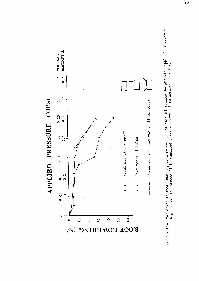
H•i
.1-.1
00 a•n-1 o
• N
•H
>, 0
•••C 0CO 1-)0
UCO • H
• 1-1
S-n
.r1 (1.)
C >
4-1 S-4O C
0) C/3000)COS-44_i a.
O 0)S-n •H
al 00
CO -a
000)• •H
•r-1
(1)3 (0O 0)r-1 S-1
1-1C/3
00• (0
4-1a a
• H 0
O
•
$-n• H 0
CO
•HS..1 00CO •H
nn•11
90
(%) oNiniamo ri aoou

- Cs1
91
a.,
1
CU
CU1-4
4-1
C-(0
-aLi
•
•1-1
t-I4-J
I I00
•ria) co
_c
oN
•Ci S.COO0
04--4
• v-1
•4441
UC
V. CU
O >
00 S-4COO
CU
•
a.)U
a)• •t=
cnco a.
CO
oo •—•
11:1$-• n-•1
(1) (1)3 *1-1
O 4-1
Cl)
Cl)
oO s-.I-i 4i
• U
C
O (0.1. 4-1
4.4
CO 0/-4
4.1 1:7CC1> -a
(h) .10011

92
0 0 0 0 0 0 0,—I C.1 crs .1- Le) 1/40
(%) DNIHTMOI awn'

93Gouilloux and Piguet 1977; Tinchon 1980; Dejean and Raffoux 1980a) and
West Germany (Nocke et al 1968; Nocke 1970; Maiweg 1981; Bohnlein 1981).
The vast majority of rock bolts in United States coal mines are
installed vertically. Inclined bolts were installed during the 1950s
and in many cases found to be very effective (Thomas 1962). Owing to
practical considerations such as longer installation time and lack of
understanding as to how they act, this practice has been discontinued.
Field studies in a US room and pillar mine by Singh (1978) could not
establish any clear advantages in using inclined rock bolts.
Monitoring of rock bolted roadways in Australia has indicated that high
axial loads can develop in the bolted roof over the centre of the
heading and very high shear loads can develop over the ribs. For this
reason vertical shoulder bolts are installed as it is considered that
angled ribside bolts can only be of assistance to reinforce the abutment
of a high arch, or "stitch" fractures (Gale 1987). The aim of bolting
in this instance is to prevent such an arch forming rather than deal
with its effects.
The physical model tests have demonstrated that where there is a high
horizontal stress field (such as is known to exist in many Australian
and US coal mines), inclining shoulder bolts over the ribsides has a
negligible effect on improving roof stability. In a hydrostatic stress
field, angled bolts gave a slight reduction in roof lowering at high
applied pressures. Where a vertical to horizontal stress ratio of 2:1
was applied, inclining shoulder bolts over the ribsides resulted in a
significant improvement in roof conditions. These bolts were able to
provide reinforcement across vertical shear fractures which developed
above the ribsides. The photographs in Figure 4.13 illustrate the
performance of the modelled roadway with angled bolts under different
stress conditions.
Studies Of Rock Bolt Pattern, Length And Density
In the preceding section it was established that angled bolts can give a
slight improvement in roadway roof conditions compared to vertical bolts
in a hydrostatic stress field. Comparative tests were performed using
other roof bolt patterns to determine their effect on roadway stability.
Figure 4.15 shows the further reduction in roof lowering that can be
achieved at high applied pressures in hydrostatic stress conditions

gl*
0 00 0Cs•I c.n
94
(t) -= •
4_1 a) ..---,,-- Ul • r-i •--;0 1-1 I-1 • •
Ca. I—.
0 cl...CO II
0
0
$-1 0 •W Ca
0 • I-I •1•J
0e •-n •L-) N
S-I
C N.1 a) ..a
CN 0
0.)
••-1 a) .-c)
a uo
r•-1 $•••
0 •r-1 >
0 a.)• 1-1 $-1
a?) C• -1 CO
LI-1 a)o
oo
co ca•r-1
1-1
CI 0.•US•••
CO a)Ca•
•t-1O:1
a) cn cuc0 4-1
0 00 caca.
4-)cu r-13 0
14-1
0 .0
0 0
)00•4S-1
4-40
•ria
00o
•r-1••n
CO CO•r-1S•4 ECOO> U
(%) DNIIIHAA.01 d0011

As the
occurred
and then
better,
in roof
95
using only a four bolt pattern (2 x 2.44 m shoulder bolts and 2 x 1.83 m
vertical central bolts). The shoulder bolts were at a shallower angle
(45 0 ) and positioned further from the ribsides (Appendix 2d). Therefore
the position and inclination of roof bolts is an important factor
influencing the critical load that a roadway roof can withstand before
failure. Optimising the location of the shoulder bolts can enable a
reduction in the number and length of vertical central bolts to be made.
In practice the installation of 2.44 m vertical bolts would prove
difficult in the restricted height of a 2.54 m high roadway, these
problems would not occur using 1.83 m bolts.
Model tests were carried out to determine the effect of the two
components of this improved bolting pattern (i.e. the 2 x 2.44 m
shoulder bolts and 2 x 1.83 m vertical central bolts) when acting in
isolation (Figure 4.165. Roadways with an equivalent height of 3.18 m
were used in these tests (Appendices 2e and 2f). The two vertical bolts
provided adequate reinforcement at low applied pressures.
pressure was increased further, considerable roof lowering
followed by the formation of fractures above the ribsides
catastrophic failure
The two angled bolts performed
withstanding moderate applied pressures without any increase
lowering compared to the fully reinforced roadway. However, when
relatively high pressures were applied, considerable roof deformation
occurred. These tests not only illustrate the importance of shoulder
bolts to retard roof failure but also emphasize the necessity to install
a complete pattern of roof bolts systematically across the width of a
roadway.
The magnitude of the stress field is an important consideration when
determining roof bolt length for the support of a roadway. Plots of
roof deformation versus applied pressure for tests using 5 x 1.22 m
vertical bolts (a common support configuration in US mines) and 5 x 2.44
m bolts (Appendix 2b) in a hydrostatic stress field are shown in Figure
4.17. At low to moderate applied pressures (simulating shallow and
medium depth roadways) the 1.22 in pattern performed in a virtually
identical manner to the 2.44 in pattern. Benefits of using longer bolts
were only apparent at high applied pressures.
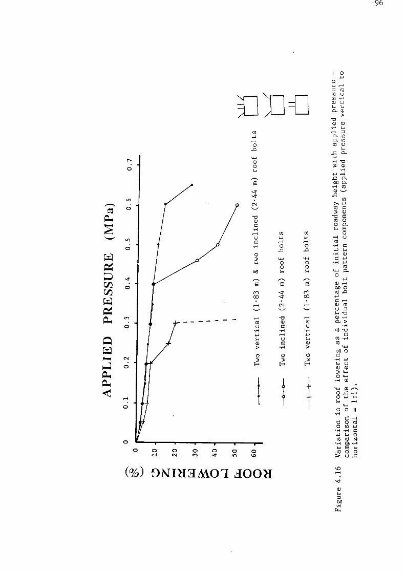
(%) NDIMOI loou
:•11
-96
0CU
OD 0
cr) ccl
00 4-)
CU
00 .6-1 • •1.4
4-1a o 11
k.0
Cs/
Cn
0
4-100
C.J
"0
C
a
0
Cr)
Li
CO
Q). >0
01-4 Cs/ C,) n43

0 0
0
0
CV Cr)
1.11
;t*
cu
▪
•
O..
I I
CCI
3 4-1
.W 0
N00
.1-1 S-10)0
>, 04-1
'17(0 (0O U1-I .1-i
CO W•r >4-)
(ll
Cl)
O 0)
(1) a.00Ca '1714-3 (ll• • n--1▪ 1-1(JO.$.4 CL.a) co
(0 (1)
cn(0 00
op a)• r-I
a)3 oo
t4-1 oO 0
O 1.4
O• a)r-I
$-n(0 (0
•rl Ca.• E(00
U
(%) DisIRIUMO rl A0011

98Roof Bolting In Weak Strata
The qualitative scale model tests described above were all carried out
using roof strata with an equivalent uniaxial compressive strength in
the range 40-55 MPa. Results of tests comparing the performance of roof
bolts (Appendix 2d) and steel work (Appendix 2a), in this model strata
and models with a roof strength equivalent to 20-30 MPa are plotted in
Figure 4.18. (The model strata configuration was similar to that
illustrated in Appendix la except the four immediate roof slabs
contained 75% as opposed to 65% sand). As was to be expected,
comparisons between similar support systems show that the higher
strength roof strata was more stable than the weaker model rock.
Bolting the weaker roof was more effective at controlling roof lowering
than using standing supports. However, the difference between the two
systems was not as marked as 'in roadways with a stronger roof.

4:1
•11=n.
....••••11
99
CO1-4co
Cn
00
OCO
.w 1 i
U)
>4-4 1-4CI 0
(+4"0 1-4
4-44-4 (0 0)00.
00 $.4t4-n 4-)
(1.1 0
o L+4 (+4 o
CO 00
00 4-40.1-45-4
-a co C
O) "C
co
co
C/)
00
a.,a.,
0
W(0(0 (4-1 o
(JO CU 4-)C(0 0000
•,-i COO
O 0 C
4-1
CI)
5-1
06 06 a) ala. 4-)
(0- (0 ca s-nLi
44-/ CO1-45-I 4-4cu op 0> > a
4-)O 0 s.4
3 3 cuE-I 1
•
4-1o 14-1
1-4
4-1 a.)oo 4-
▪
) II$441
CO
44 r—I
OZ/
• r-I
• 0 0
O W N.4-1 4,1
4-1 $-4 /.4
CO CZ 0
-1-1
E(0 000
c.) 4-1
(%) osiniamo ri aomi

100
CHAPTER 5
DESIGN THROUGH IN SITU MEASUREMENT DURING EXCAVATION
5.1 Background
Detailed systematic monitoring of the behaviour of roadway support
systems and the surrounding rock mass will provide data to assess the
stability of the excavation and design a suitable support system.
Instrumentation and monitoring has been carried out in British coal mine
roadways for many years to evaluate support performance (Potts 1955,
1957; Thomas 1966). It also forms an important part of the New Austrian
Tunnelling Method, now used regularly for civil engineering projects.
5.2 Rock-support Interaction
Bieniawski (1987) states that "the behaviour of an opening and the
performance of the support system depend on the load-deformation
characteristics of the rock and the support, as well as on the manner
and timing of installation". This concept can be described by the use
of ground support interaction curves as shown in Figure 5.1 (Deere et al
1970; Brown et al 1983). The curve illustrates the load that must be
applied to the surface of an excavation to prevent excessive deform-
ation.
5.3 New Austrian Tunnelling Method
Recognition of the gradually increasing deformation of excavated rock
masses is the basis of the New Austrian Tunnelling Method (NATM). It
was developed in the late 1950s and early 1960s (Rabcewicz 1964). NATM
is not actually a construction method but more of an approach or
philosophy integrating the principles of the behaviour of rock masses
and monitoring the behaviour of underground excavations during constr-
uction. The essential elements of this philosophy have been outlined by
Muller (1978), Brown (1981) and Bieniawski (1984), and are as follows:
(a) Mobilization of the strength of the rock mass.The method relies on the inherent strength of the surrounding rockmass being conserved as the main component of tunnel support.Primary support is directed to enable the rock to support itself.It follows that the support must have suitable load-deformationcharacteristics and be placed at the correct time.
(b) Sprayed concrete protection.In order to preserve the load carrying capacity of the rock mass,loosening and excessive rock deformations must be minimized. Thisis achieved by applying a thin layer of sprayed concrete, sometimestogether with a suitable system of rock bolting, immediately after

101
R.idialSUrrOrl
pr rk,1Ire
In Situ stress prior to excas ation
Linear elastic deformation
Start of failure of rockAr......„/ surrounding tunnel
Load-deformationcurse for tunnel
Support reactioncurves
Radial deformation( = Function of time)
Support mall inn curses
(= Load induced in support In deformation of excavation.)I. Stiff support installed too earl) attracts excessive load.
2. Effecti ve support at A. pressure required to limit deformation = pressure asailable from support; tunnel and supportsystem in equilibrium.
3. Ineffective support not stiff enough and installed too late.
Figure 5.1 Load-deformation curve for rock mass and support system.

102
face advance. It is essential that the support system used remainsin full contact with the rock and deforms with it. While the NATMinvolves sprayed concrete, it does not mean that the use of sprayedconcrete alone constitutes the NATM.
(c) Measurements.The NATM requires the installation of sophisticated instrumentationat the time the initial sprayed concrete lining is placed, tomonitor the deformations of the excavation and the build-up of loadin the support. This provides information on tunnel stability andenables optimization of the formation of a load bearing ring of rockstrata. The timing of the placement of the support is of vitalimportance.
(d) Flexible Support.The NATM is characterized by versatility and adaptability leading toflexible rather than rigid tunnel support. Thus, active rather thanpassive support is advocated and strengthening is not by a thickerconcrete lining but by a flexible combination of rock bolts, wiremesh and steel standing support. The primary support will partly orfully represent the total support required and the dimensioning ofthe secondary support will depend on the results of the measure-ments.
(e) Closing of invert.Since a tunnel is a thick-walled tube, the closing of the invert toform a load-bearing ring of the rock mass is essential. This iscrucial in soft-ground tunnelling where the invert should be closedquickly and no section of the excavated tunnel surface should beleft unsupported even temporarily. However, for tunnels in rock,support should not be installed too early as the load-bearingcapability of the rock mass would not be fully mobilized. For rocktunnels the rock mass must be permitted to deform sufficientlybefore the support takes full effect.
(e) Contractural arrangements.The above main principles of NATM, will only be successful ifspecial contractural arrangements are made. Since the NATM conceptis based on monitoring measurements, changes in support andconstruction methods should be possible.
(f) Rock mass classification determines support measures.Payment for support is based on a rock mass classification aftereach excavation round (Figure 5.2a)
NATM is now applied worldwide in civil engineering projects, some case
studies have been described by Atrott (1972), Rabcewicz and Golser
(1974), Zillessen (1978), Yagi (1978), John (1980), Babenderde (1980),
Daly and Abramson (1986), Wallis (1986, 1987) and Martin (1987). In
addition its use in the German and Korean coal mining industries has
been reported by Albers et al (1982), Spaun and Jagsch (1983), Maidl
(1984) and Lee et al (1987). Some tunnelling engineers consider that
the characteristics of Swellex bolts (Section 14.4) make them suitable
for use with NATM. The bolts can be quickly installed directly after
excavation, providing immediate support and preventing loosening of the

103A x xCA.AT ON AREA
ROCK BOLTSWIRE MESHINSULATIONCONCRETE LININGSHOTCRETE
ROCK BOLTSSTEEL ARCH
_ LINER PLATES---- INSULATION
CONCRETE LININGWIRE MESHSI-10TCRETE
•
• CLASS iiiaCLASS I
CLASS HA 40 9 •
A 40 9 •
A HO
CLASS III bA NO 0
CLASS V• 102.4
CLASS IVA 100 B en7
,•
/
MA,
a. Support measures according to rock mass classification.
•
E
MA,
ODE.• /.1
14.-PM PD•
--Y. MA,
E.
-
-MA MA•
I, ROOF SETTLEMENT
H. HI HORIZONTAL CONVERGENCYPRIMARY SUPPORT
I. HORIZONTAL CONVERGENCYCONCRETE LINING
E TRIPLE EXTENSOMETERSMA MEASURING ROCX BOLTS
GO ROCK PRESSURE CELLS
" BO CONCRETE PRESSURE CELLS
b. Geotechnical measurements.
Z VO
9'
2 E .omy0 -u. 30...
o
-TOH'
IF
I ,
..
IF..'
II 0...,^ WI.,. -,‘A` 7+
\IV-
MIn 0"!
...p ,....
lir1
0
IP 111111
i , 1 I l ',F A
- ....4,1:,
z g;0 o ,
.-E-;
.. TH NNWr =MIN WC IPIMNE V'g'""VMNW"-- Minn VT" V !If
IA0 - a
i v . • • • VEIN•'' nIr ...
0 ADDITIONAL ROCK BOLTING-, SOO
VI tat':, 2 400
P- 300• 2to). 200
CC gj. 100'0
ilij%'-1111-'11:139'1111
AN I I II
El I L I 1 1 11KM I I I
•N ENLARGED CROSS - SECTION FOR THE PARKING AREA
El EXCAVATION INTERRUPTED
c. Correlation of results of geotechnical measurements with support.
Figure 5.2 Construction of the Arlberg Tunnel (after John 1980).

104
rock during stress redistribution and blasting operations. Case
histories using Swellex have been reported by Schmid (1986) and Muller
(1987).
5.4 Roadway Instrumentation
5.4.1 Background
The amount and type of instrumentation used to monitor a rock bolt
support system will vary depending on the nature of the site. Generally
simple, robust instruments based on mechanical principles, that can be
quickly installed, are preferable to more sophisticated electronic
devices. A thorough geotechnical survey should be made at each
monitoring station. Ideally this would involve drill core logging,
laboratory testing and petrographic analysis of rock samples. A
detailed knowledge of the geology of a monitoring station will assist in
the interpretation of measurement data.
Monitoring stations should be established as close to the head end as
possible. Generally measurements are taken daily for the first few days
after installation, weekly for the next two or three weeks and then at
monthly intervals (unless circumstances change such as the influence of
abutment pressures from a longwall face). Establishing a monitoring
section whenever support or excavation parameters are altered will
provide the necessary data to determine the optimum roadway geometry and
support system.
5.4.2 Convergence Measurement
Roadway closure can be measured directly with a tape between fixed
reference points set in the strata around the roadway. A typical
section will have a roof point and a floor point in the centre of the
roadway as well as points located half-way up each rib. Measurement
between these points and taut lines joining opposite points enables the
determination of roof lowering, floor heave, right lateral closure and
left lateral closure.
Greater accuracy can be achieved using a tape extensometer or convent-
ional surveying techniques. For continuous recording of vertical
closure a convergence recorder may be installed between caps on the
reference points. This device is easily disturbed and should only be
placed where it will not be subjected to interference (from shot firing,
free steered vehicles, passing mine workers etc.).

105
Relative lateral movement of roof and floor strata is measured by means
of a plumb-bob, lateral flow plate (or protractor) and tape. The plumb-
bob is suspended from the roof reference point and hung directly over
the plate located on the floor point. The postion of the plumb-bob on
the plate will indicate any lateral movement by direct measurement from
the centre of the plate.
Measurements are recorded in relation to time or distance from the head
end/longwall face. Plotting convergence trends will give information on
roadway stability (Figure 5.3). Convergence measurements were used for
design purposes during the construction of the Arlberg Tunnel in
Austria, using the NATM (John 1980). If deformation rates greater than
25 mm per day occurred, additional rock bolts were installed; if
deformation declined, rock bolting was reduce during further driving
(Figure 5.2). The criterion adopted here are site specific and cannot
be used for other rock conditions without study.
5.4.3 Borehole Extensometers
The use of borehole extensometers for pre-excavation determination of
rock bolt length is described in Section 2.4. Extensometer measurements
in bolted strata can give information on the development of potentially
hazardous conditions at an early stage. Separation of the bolted
section en masse due to fracturing along a plane just above the top of
the bolts will be detected via anchors located above the bolted section.
Should this occur alterations in bolt length must be made. Excessive
bed separation within the bolted section necessitates increasing the
rock bolt density and/or installation of additional standing support.
There are several different extensometer anchors available. The anchor
system used is determined by the nature of the strata and type of
extensometer.
Wooden wedge anchors are only suitable for use as a top anchor. They
are simple and inexpensive but can be a problem to install. A short
length of wooden dowel is cut diagonally and held together with tape.
It is pushed to the top of the borehole using a rod, a sharp tap then
breaks the tape and the bottom section is forced up as a wedge to form
the anchor.

106
Time
Time
a. Stable situation. b. Becoming stable.
Can measure less often. Can measure less often.
Time
Time
c. No decrease in rate. c. Rate increasing.
Must watch closely. Potential instability,
additional support required.
Figure 5.3 Convergence trends.

107
Spring anchors can vary in complexity from simple torsion springs or
spring clips to anchors with several trailing leaf springs. They are
easily positioned in the borehole using a plastic pipe or length of
conduit.
Expansion shell anchors are generally limited to single or double
position extensometers. They consist of mechanical expansion shells
similar to those used for point anchored rock bolts (Section 7.3). They
can be rapidly installed and are particularly suited to rough, uneven
boreholes in fractured strata.
Snap-ring anchors are positioned- through removal of a locking pin by
pulling a cord which allows retaining rings to snap outward and grip the
borehole. These anchors are most suited to smooth uniform boreholes.
Grouted anchors require pre-assembly of the extensometer system before
insertion, which can be time consuming. Actual installation is
accomplished quickly if the proper procedures are followed. No-shrink
cement grout or resinous grout can be used. This type of anchor will
not slip under tension in blasting areas.
Borehole extensometers can be classified as either single- or multiple-
point devices. Some of the more commonly used types are described
below.
Single point extensometers simply consist of a length of wire or rod
anchored in a borehole (a point anchored rock bolt without an end plate
can constitute such an extensometer). Changes in the distance between a
reference point on the end of the wire or rod and the borehole collar
are indicative of ground movement taking place between the anchor and
the rock surface.
Single point Swellex extensometers consist of a modified Swellex bolt
(Section 14.4) which acts as a single point rod extensometer (Atlas
Copco 1982a). The upper 0.5 m of the bolt is installed as a point
anchor by fitting a thin steel tube over the remainder of the bolt to
prevent expansion during installation. The lower bushing is not welded
to the bolt so that as the strata separates, the bushing is pushed along
the bolt. The bushing end is machined to give a surface suitable for
accurate measurement using sliding calipers. The ground movement

108
monitoring bolts are either the same length as the standard bolts to
measure rock movement within the bolted section or longer to record
movement above the bolts.
Multiple-point tensioned wire extensometers consist of lengths of high
strength stainless steel wire connected to each anchor and tensioned by
either dead weights, coil or leaf springs, cantilevers, or constant-
tension clock-type springs at the mouth of the borehole. The simplest
type utilizes spring clip anchors in a vertical borehole. Wires from
the clips are installed through a reference plug at the borehole collar;
a constant tension is maintained by a weight attached to the end of the
wire. Movement of a reference point on the free end of the wire
relative to the reference plug indicates strata displacement. Measure-
ment of this distance can be made with a vernier caliper or graduated
scale. More sophisticated devices are commercially available whereby
the wires are tensioned by spring cantilevers in the sensing head at the
borehole collar. Anchor movements will either stress or release the
wires. Transformers attached to the cantilever beams convert the
mechanical movement to changes in electrical quantities; electrical
resistance or vibrating wire strain gauges are commomly used for this
purpose. Neff (1970) has described the necessary calibration procedures
and sources of error incurred with these instruments.
Multiple rod multiple-point extensometers are simple, accurate and
generally very reliable. Each measuring rod is freely suspended from an
anchor. The rods follow the anchor movements which are sensed by
measuring the position of the tip of the rod relative to a reference
plate at the mouth of the borehole. This movement can be read mechan-
ically with a depth micrometer, or electrically using a linear voltage
displacement transducer, rotary or linear potentiometer. Measurement
errors due to rod corrosion are prevented by using a stainless steel
tip. If the anchors are secured by a grout, the rods should be encased
in a pipe or tube to prevent contact with the grout. The number of
anchors within a rod extensometer is limited by the diameter of the
borehole. A 43 mm diameter hole is only capable of containing four rods
(Whittaker and Scoble 1980); ten point multiple rod extensometers are
available for boreholes with a diameter greater than 60 mm.
Single rod multiple-point extensometers have a high resolution and
consist of a series of electrical transducers mounted between anchors
within a borehole which measure relative displacement between these
109
points (Bourbonnais 1985). The measuring systems are in water tight
casings inside the hole and consequently not as susceptable to shock
waves created by blasting as borehole collar electrical measuring
devices.
Multiple-point magnetic extensometers have been used successfully in
many British coal mines over recent years. Strata deformation is
determined by monitoring the location of magnetic targets within a
borehole. A magnetic ring, cut from magnetized strip, is fitted to a
spider anchor consisting of a cylindrical PVC mount with multiple
trailing leaf springs. An open reed switch fixed to the end of a series
of probe rods closes on entering the magnetic field induced by a ring
magnet. This activates an indicator light on an intrinsically safe
multimeter connected to the probe. The position of a magnet is measured
(by means of a tape attached to the, rods) at a reference point on the
free end of a pipe which runs the runs through the rings and is fixed at
the top of the hole (Figure 5.4). In the majority of field conditions
this gives a reading accuracy of ±1 mm. A micrometer system can be used
for greater accuracy. Lateral movement of strata may prevent access up
the pipe.
5.4.4 Alarm Systems
Single-point extensometers can be modified to act as an alarm system to
give a visible warning of impending failure of the roof. Alarm systems
are ideally simple, inexpensive and easy to install, but are only
capable a specified degree of rock movement. The amount of deformation
occurring before rock failure will vary from site to site, consequently
for an alarm system to be effective the degree of rock movement that can
occur before conditions become hazardous must be determined at each.
location by experience through detailed monitoring programmes. Some
alarm systems that have been used in US mines are described below.
Roof sag bolt: A bolt point anchored in stable strata above the bolted
section. Three strips of different coloured reflective tape are
attached adjacent to each other at the end of the bolt. As roof
lowering occurs each strip is progressively hidden behind a plug at the
borehole mouth.
Glowlarm: A flexible translucent plastic tube containing two chemicals
in separate glass amphiboles is installed on a metal sling tight against
the rock surface, suspended from a wire point anchored in stable strata


111
above the bolted section. Rock deformation bends the device, breaks the
glass and mixing of the two chemicals produces a bright yellow light
which lasts up to 24 hours.
The Spider and the Guardian Angel: Installed on the end of a bolt point
anchored in stable strata at least 0.3 m above the bolted section. A
specified amount of roof deformation releases a reflective drum or flag
(Guccione 1978).
5.4.5 Borescopes
A borescope is an optical viewing instrument for visual or photographic
observations in a borehole. There are a variety of instruments known by
names such as, introscope (Thomas 1966), stratascope (Fitzimmons et al
1979), endoscope (Dejean and Raffoux 1980b), petroscope (Adams and Jager
1980), borescope (Mahtab et al 1973) and the ST-6 Arvin Diamond TV
camera (Herget 1982). The most versatile of these are the flexible
fibre-optical instruments operated using a standard colliery cap lamp
and battery as a power supply.
Specific problems that can be tackled using borescopes have been
discussed by Shepherd et al (1986) and are as follows:
(a) Mapping lithological variation in a mine roof.
(b) Identifying fracture distribution and type in relation to litho-
logies and making inferences about roof failure mechanisms.
(c) Assistance with determining support requirements, especially bolt
length and checking the efficacy of bolting together with other
techniques such as bolt load tests.
(d) Checking and monitoring of roof stability, used in conjuction with
extensometer and convergence measurements.
(e) Analysis of spatial and temporal distributions of roof fractures,
especially for examining the effects of higher loading adjacent to
goaf edges and in longwall gateroads.
5.4.6 Rock Bolt Load Measuring Techniques
Additional support or a reassessment of existing rock bolt parameters
may be required at locations where bolts are heavily loaded. Instru-
ments for measuring the load acting on a rock bolt can be classified
into one of two general categories; either, external and single point
internal devices, or axial and multi-point internal devices. Details of
commonly used intruments in both of these categories are given in the
following paragraphs.


113
a dial gauge is not perfectly linear in the measurement of displacement,
consequently a micrometer should be used for very high accuracy
instrumentation.
Rubber Compression Pad
The roof bolt compression pad is an inexpensive load measuring device
developed by the USBM in 1951 (Obert and Barry 1955). It consists of a
rubber disc located between two steel plates. Loading of the pad causes
changes in the circumference of the rubber membrane which is measured
with a calibrated ring gauge. These readings are converted to bolt load
values by reference to a calibration chart (Sen 1958). The compression
pad is a very low precision instrument; Tadolini and Ulrich (1986) quote
an accuracy of ±0.9 kN at low loads, ±45 kN at high loads and a working
load limit of 142 kN. The material properties of rubber limit the use
of compression pads particularly where cyclical loading may occur.
Laboratory tests by Cyrul (1985) have shown classical primary and
secondary creep of a rubber used for dynamometers.
Photoelas tic Dynamometer
The design and development of a number of types of photoelastic trans-
ducer was undertaken by research workers at the University of Sheffield
Postgraduate School in Mining and has been reported by Roberts and
Hawkes (1963, 1965). A photoelastic rock bolt dynamometer is a robust,
self contained device. It consists of a hollow steel cylinder con-
taining a glass disc. When loaded diametrically the disc is strained.
The number of photoelastic fringes revealed when observed with an
optical viewer can be related to the load on the cylinder. With experi-
ence it is possible to read the instruments to an accuracy of 2.5 kN. A
maximium of six fringes can be distinguished which limits the load
range; one supplier markets a dynamometer pre-set in 70 kN increments
within a 0 to 150 kN range (Perard Torque Tension 1985). Remote reading
of these instruments is not possible and the necessity to gain close
access to the dynamometer for reading creates major limitations.
Hydraulic Load Cell
Hydraulic load cells are generally robust and reliable instruments. The
annnular ring cell is filled with de-aired hydraulic fluid. When a
compressive load is applied the pressure in the fluid changes. This is
measured by a pressure gauge fitted to the cell or a diaphragm trans-

114
ducer; remote monitoring is possible by using an electronic pressure
transducer. The flatjack U-cell used by the USBM can measure loads of
up to ±90 kN and are accurate to ±2.2 kN (Chekan and Babich 1982).
Annular-ring Vibrating Wire Dynamometer
Vibrating wire load cells are high resolution instruments. A number of
vibrating wire transducer elements are positioned longitudinally
equidistant around the mid-circumference of a steel cylinder. Changes
in the natural frequency of vibration of a stretched wire within the
elements occurs when the cell is loaded. A square law exists between
strain change and observed frequency change. Readings from vibrating
wire strain gauges are unaffected by cable length and are therefore
suitable for use in remote monitoring.
Electrical Resistance Strain Gauged Load Cell
Electrical resistance strain gauges are a form of transducer which
converts a 'dimensional change into a resistance change. The most
accurate dynamometers are set in a full Wheatstone bridge configuration
to compensate for temperature changes and eccentric loading. The use of
high resistance strain gauges will minimize cable effects. A simple
rock bolt dynamometer was developed by the NCB Mining Research
Establishment in the late 1950s to early 1960s. It consists of a collar
containing two vertical sensite gauges and two horizontal compensating
gauges. Under axial load the resistance of the longitudinal gauges
decrease owing to axial shortening, while the resistance of the
circumferential gauges increases. To measure this, a voltage is applied
and the resistance compared with standard resistances using a transistor
dynamometer test set. Thus readings can only be taken by trained
personnel with the necessary equipment. A more sophisticated dynamo-
meter was developed (Potts 1957; Smith and Pearson 1961) by the
Department of Mining Engineering, King's College, University of Durham
(now University of Newcastle Upon Tyne). It used eight 340 0 gauges,
four active and four compensating, connected to a four arm Wheatstone
bridge circuit. The development of another full-bridge dynamometer by
the USBM, using a titanium diaphragm, has been described by Beus and
Phillips (1974). It has a usable range of ±89 kN and is accurate within
±1% for vertical loading and ±5% in angle loading (Langland 1977).

115
Vibrating Wire Instrumented Rock Bolt
Mounting a dynamometer within the bolt head reduces the risk of
instrument damage by mining operations. Dynamometers are available
suitable for coupling to a standard rock bolt within a borehole. They
contain a miniature vibrating wire strain gauge transducer positioned in
a hole along the central axis of a cylinder. This system has the same
advantages as the external vibrating wire dynamometers; it works on a
similar principle although it is 'primarily designed to measure tension
rather than compression. Bellier and Debreville (1977) describe a
150 kN internal dynamometer that has a stress sensitivity of
approximately 0.2 MPa. Another similar type of vibrating wire
instrumented bolt which can be read by touching the bolt head with a
hand-held probe has been evaluated by Maleki (1985).
Bolt Surface Strain Gauges
A simple internal load measuring device can be constructed by mounting
two strain gauges (vibrating wire or resistivity) 180 0 apart on the bolt
collar. However, electrical leads from the gauges may be a problem
during bolt installation.
AXIAL AND MULTI-POINT INTERNAL DEVICES
Axial and multi-point internal devices are capable of measuring the load
acting on a full column anchored rock bolt.
Single Point Rock Bolt Extensometer
The mean load acting on a rock bolt can be determined by measuring its
total extension. This may be achieved by using a standard rock bolt
with an axial hole along the centre. An unstressed rod is fixed in the
hole by a weld at the far end. Measurement of relative movement between
the exposed end of the bolt and the free end of the rod gives the total
bolt extension (Ward et al 1976). The measurement is taken simply with
the end of a caliper or a dial gauge screwed onto the bolt. An
electrical transducer can be attached for remote monitoring. Altounyan
(1986) has developed a spring loaded 10 kl linear potentiometer suitable
for single point rock bolt extensometers which are read using an
intrinsically safe multimeter, portable data logger or through
connection to a MINOS outstatiot for transmission to the surface.

116
Multi-point Rock Bolt Extensometer
This is a similar device to the single point rock bolt extensometer
except it has several unstressed rods (Bellier and Debreuille 1977) or
wires (Farmer and Shelton 1978) fixed at intervals within a hollow bolt.
It is capable of determining the position of zones where load is taken
up along the bolt and can therefore be used to assess the most favour-
able bolt lengths. Laboratory calibration of simple mechanically
measured wire rock bolt extensometers used by Farmer and Shelton (1978)
showed they were sensitive to ±1 kN.
Resistance Strain Gauged Rock Bolts
Electrical resistance strain gauges positioned at a number of points
along the length of a full column anchored rock bolt can give inform-
ation regarding axial strain and force, bending strains, and shear
stresses generated along the rock bolt. The strain gauged bolt
developed by the US Mining Enforcement and Safety Administration (MESA)
has been described by Sawyer and Karabin (1975) and Sawyer and Eakin
(1976). Prototype bolts were produced which used quarter Wheatstone
bridges. These gauges did not compensate for temperature changes or
nullify bending stresses induced during installation. The final design
adopted had temperature-compensating, half Wheatstone bridges. Two
gauges were placed on each arm of the bridge with each gauge mounted in
diametrically opposite positions to nullify the effects of bending.
Three sets of these gauges were located along a bolt. Similar designs
of strain gauged bolts have been employed worldwide. For example, their .
use has been described by Wade et al (1977), and Patrick and Haas (1980)
in the USA; Bello and Serrano (1974) in Mexico; Walton and Fuller
(1980), and Gale and Fabjanczyk (1985) in Australia; Bjornfot and
Stephansson (1983) in Sweden and Freeman (1978) in the UK. Resistance
strain gauged rock bolts installed in harsh underground environments can
prove unreliable, as was found to be the case in the construction of the
an inset of North Selby Colliery (Tully 1985). Plots of axial forces
and point bending moment developed by a set of bolts, contoured above
the roadway, will delineate the geometry of loading (rock failure) and
the location of shear reinforcement respectively (Gale 1986). These
plots can be used to determine the onset of bolt yield and the need for
additional reinforcement or alteration of the installed bolt length/
orientation.

1175.5.7 Standing Support Load Measuring Techniques
Reaction loads generated on free standing supports can be determined
from load measuring devices placed on or under the support.
Hydraulic and electrical resistance strain gauged load cells are
available. These are placed underneath steel supports and normally
located in a carrier. Where wooden supports are used under girders in
rectangular roadways, the load cells may be placed between the top of
the post and the girder (Figure 5.4). This will provide easier access
for measurement and recovery of the cell.
Strain gauges such as the surface mounted vibrating wire type, provide
an alternative to load cell as a means of measuring loads on steel work.
They are generally inexpensive, simple to install and highly accurate.
Intrinsically safe readout equipment is available. Interpreting the
measured data may be problematical due to complex bending and twisting
loads.

118
CHAPTER 6
PRELIMINARY INVESTIGATIONS FOR ROCK BOLTING SYSTEMS IN
THE DEEP HARD/PIPER SEAM IN NOTTINGHAMSHIRE
6.1 Background
The neighbouring collieries of Mansfield and Sherwood are at present
working the 2.3 m to 3.0 m thick Deep Hard/Piper Seam at depths of
between 500 m and 600 m. Information gathered from preliminary
investigations for rock bolting systems at these collieries has been
used to evaluate some of the design methods discussed in Chapters 3 and
4 and to make recommendations concerning rock bolt parameters and
monitoring methods for futher design by in situ measurement.
As subsidence is a very serious problem in the Mansfield conurbation,
methods of mining have been designed to overcome this particular
disadvantage. Both collieries have planned a system of single entry
retreat workings (Figure 6.1), which entails retreating down a pre-
driven roadway, allowing it to collapse behind the face-line. With a
one-road system, the stability of that roadway is vitally important. At
Mansfield Colliery the use roof bolts is being considered, as a rein-
forcement supplementary to the existing flat topped roadway supports.
This system has been designed to use 45 m long faces and initially 45 m
wide pillars which should considerably reduce surface subsidence.
At Sherwood Colliery an additional method of working has also been
adopted. It involves driving a series of 5.5 m wide headings by means
of a Dosco In Seam Miner 3000 giving a partial extraction system (17%
extraction) anticipated to eliminate any surface subsidence (Figure
6.1). If this method of mining is successful, vast areas of coal could
be released from sterilization. It is intended to support the wide
roadways with bolts and rectangular shaped standing supports as
indicated in Figure 6.2.
The preliminary investigations have involved engineering geological
mapping of the roof strata and a programme of mine roadway instrument-
ation and monitoring. The position of the measuring sections are given
in Figure 6.1. Convergence stations were established with short point
anchored bolts to monitor roof lowering, floor heave and lateral closure
of the openings. Multipoint magnetic extensometers were installed in
the roadway centre to measure and precisely locate points of differ-

119
I I
›
m
Ld
MANSFIELD TOWN PROTECTION AREA .
TURN
130
2
0 500
1
metres
Figure 6.1 Sherwood/Mansfield Colliery Deep Hard/Piper Seam.

120

121ential strata deformation. In addition, pressure cells were placed
along the RSJ girder to determine support loading. The field
investigations were backed up by laboratory testing of rock specimens,
stress abutment calculations and a series of scale model tests.
Roof conditions in the Deep Hard/Piper seam are generally very sound,
however, this study has revealed that there are several factors which
could lead to unstable roof conditions within this seam at Mansfield and
Sherwood Collieries.
6.2 Geotechnical Evaluation Of Roof Strata
The roof consists of a medium to silty mudstone overlain by a fine
siltstone which is covered by a fine sandstone or siltstone with
sandstone laminae and layers.
There are well developed parting planes present in the roof. Two
principal parting planes occur at lithological boundaries which are
generally present throughout the area of the Deep Hard/Piper combined
seam at the two collieries. Positions of the two planes relative to the
top of the seam are shown in Figure 6.3.
The first parting plane occurs at the mudstone - fine siltstone inter-
face and is sometimes poorly developed. It generally lies between 0.5 m
and 0.65 m above the seam, although localised thinning of the immediate
mudstone unit can result in it descending to within 0.15 m of the seam.
Bed separation at this horizon can lead to collapse of the immediate
mudstone unit. However, allowing the roof to break away at this level
during drivage can assist in achieving a consistent and regular roadway
profile to which flat topped supports can be set. There is often a very
well developed second parting plane along an erosion surface at the top
of the fine siltstone bed (Figure 6.4). It is usually present at
between 2.3 m and 2.5 m above the seam; however, localised thinning or
thickening of the underlying mudstone/silty mudstone and fine siltstone
units can reduce or increase its position above the seam. Bed
separation can occur at this parting resulting in excessive loading on
supports.
Laboratory tests have been carried out on roof samples collected from
202's roadway and 131's Main Gate. Rock has also been tested from
boreholes drilled into the roof at 130's and 127A's face end lines.
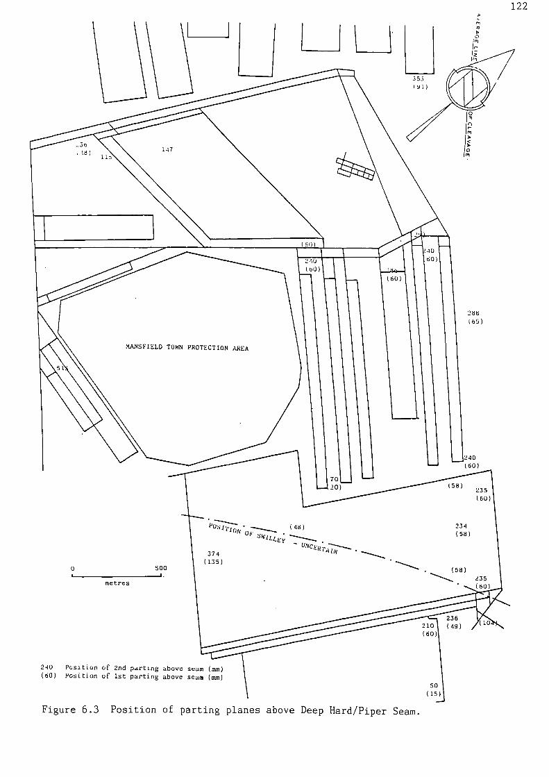
1'1
3531911
0
288b3)
MANSFIELD TOWN PROTECTION AREA
240(60)
(58)235(60)
3740Nch:W7,4-11‘7--..
P°SITION.(48)OP swILLE;
(135)0 500
metres
210(60)
240 Position of 2nd parting above seam (mm)(60) Position of 1st parting above seam (mm)
50(15)
122
Figure 6.3 Position of parting planes above Deep Hard/Piper Seam.

Figure 6.4 Parting plane along erosion surface
124Figures 6.5a, 6.5b and 6.5c are geotechnical logs of the three vertical
boreholes. All the holes were drilled a considerable time after the
roadway or face was excavated. The immediate mudstone was absent, it
had probably broken away to the first parting plane, leaving an open
hole at the base of the cores. Bed separation had resulted in missing
core in the 130's boreholes between 1 m and 2 m above the roadway.
The cores were highly fractured (Figure 6.6). It was impossible to
distinguish between natural or mining induced fractures and those caused
by man handling of the core during and after drilling. Before arriving
at the testing laboratory the cores had been left on the surface in sub-
zero temperatures for several days; this may have had an adverse effect
on the rock. The values for RQD and fracture spacing obtained from the
borehole cores were therefore highly distorted. In addition, corrugated
sheet lagging above the standing supports in the in-seam roadways and
wooden boards behind the arches in the drifts down to the seam, obscured
large exposures of Deep/Hard Piper roof rock, preventing the use of scan
line techniques for fracture logging. Realistic values of RQD and
fracture spacings of 60% and 150 mm respectively were estimated from the
limited exposures of roof strata. The high degree of fracturing,
particularly in the lower sections of the core, limited the number of
standard sized test pieces that could be obtained. Those that were
tested probably came from relatively competent parts of the sample
section, such as ferruginous bands. However, it would appear that the
roof strata, when unweathered, is of adequate strength in both tension
and compression.
Slake durability tests on the fine siltstone from the boreholes suggest
that this stratum can deteriorate rapidly in the presence of water. The
samples tested underwent partial or completed disintegration after a
week of immersion.
Relatively low values from toughness and abrasivity tests obtained for
the mudstones and fine siltstone units indicate that bolt hole drilling
and excessive drill bit wear should generally not be a problem.
However, where drilling into the overlying sandstone/siltstone bed is
necessary, rapid bit wear could occur.
Swilley structures have been observed in several seams within the
Nottinghamshire coalfield (Elliott., 1965). A major swilley has been
proved in the initial Deep Hard/Piper developments at Mansfield and by

1
GEOTECHNICAL LOG
:..N
S'
e.
:
,
-.:, ...,
. i .
r-0.-
. ...,
. .
'.., ,.' .
..
...
'
A n!
%
41,
SANDSTONE Fine with micaceous curb-onaceous laminae, well developedripple sets, several minorerrosive surfaces, highlydisturbed lamination from 9.67 to9.40, numerous irregular horiz-ontal and low angle fracturesalong carbonaceous laminae(passage)
• •. •• .• .
... .."•:•-;-:..•:•. •. . . :
.,-.. .
...... .. . . .
... . .. . .
.
•
. • .• . • • • .
11
10
.,..—
SILTSTONE Medium to coarse, San.-stone fine irregularly interlamin-ated 6 interlayered, few micaceouscardonaceous partings (passage)
SANDSTONE Fine wt 51 y aminde -,-;-'.',',.
. .:;.
-.
•
•
i I 1 • n ii II •al
ei
amm...m.
40..., .._ ,
,Lekliv:4::: . 4?
mas
n nwi
I. 0
.. .::
V..
.5 5,, 5w0
0.
Su I., Ilu ,.. v..,•, 5 .,, ., , 21
str.nktOIs./ 1..0
.1
Dcscriptton of strAt• SyobolLe a.• ""log
floor 1•I
Drill site: Sherwood Colliery, British Coal Nottinghamshire AreaLocation: 130s Tailgate/Face end line junction
Date excavated: 3/12/83 Date drilled: 5/11/86 Core dia.: 54mmDate or lithological log: 7/11/86 By S LunnonDate of geotechnical lug: 20/1/87 By D M TullyDate tested: 25,2/87 By T D Boyce
Figure 6.5a Geotechnical borehole log - 130's tailgate/face endline junction.

126
GEOTECHNICAL LOG
•
. ,
SANDSTONE Fine, with micaceous an.micaceous carbonaceous laminae;well developed ripple sets,lamination highly disturbed from
.,,,....
.4-.:•:•.4-:
:•:;-...:•4.
.
f..0.:,
9.73 to 9.50; common sub–horizontal: : : .. '.: --11
.V&A.-
and low angle irregular fractureson micaceous carbonaceous laminae,(passage) :.:-:.:4-,
.:.:.:-..:4,:•:-:-;-!-•
' _ . • •:.-.• :.-.2,-.
•
1-•• • "• •• •
•• g: .•. • '. •. •
,........
SANDSTONE me, wit si s one anmicaceous carbonaceous laminae inthin Ia ers 60:40 ri le drift
. , SILTSTONE Medium to coarse withdiffuse sandstone laminae & thin
--layers 70:30 to 80:20 downwards; 8---, few micaceous carbonaceous surfaces= —
SILTSTONE Medium to coarse & sand-stone fine irregularly interlamin-
. ated & interlayered, (passage) —.—, e
SANDSTONE Fine with siltstone lam–..
- inae & thin layers 70:30 to rare '...:,-;-,:
.downwards, micaceous/carb laminae ......-
, ,
...0.,t
..,..
f.
SILTSTONE Fine, few diffuse sandypatches at top; core fragmented inparts; ironstone bands; few sub-vertical and common horizontal non
fractures; becomespolished muddytowards base
..7: : –
.
e
Open hole --
..
. 5 Su 75 fu luu I 5 u1./U ,. n I Ues.crLptLon of •tr.at. Sy.bul Le Dia on,.111 •P•n • ,n ig ...I> ....... lug r .•...., ...• n
vo. .) flu,. 1•1
Drill site: Sherwood Colliery, British Coal Nottinghamshire Area .Location: 130's Face end line 10 in from Tailgate
Date excavated: 11/9/86 Date drilled: 5/11/86 Core dia.: 54 mmDate of lithological log: 7/11/86 By S LunnonDate of geotechnical log: 22/1/87 By D M TullyDate tested: 2/3/87 By T D Boyce
Figure 6.5b Geotechnical borehole log - 130's face end line 10 mfrom tailgate.

SILTSTONE Fine muddy, poorly laminated; common low angle fractures
.;1LTSTONE Fine/medium, poorly lam-inated, few muddy patches, commongenerally low angle planar andirregular fractures, few plantdebris
lb
15
SILTSTONE Fine, poorly laminated,muddy patches, ironstone lenses andthin layers, common generally lowangle planar and irregular fract-ures, few plants, (passage)
SILTS1ONE Fine/medium, poorly laminated, low angle sub-horizontalplanar and slightly irregularfractures; few plant debris,(passage)
SILTSTONE Medium, very poorly lamin-ated, diffuse ferruginous patches,
low angle planar fractures, plants
SILTSTONE Medium with diffuse sandylaminae and thin layers, 80:20ferruginous patches, low angle/sub-horizontal planar fractures,(passage)
14
ii
12
11
10
SILTSTONE Fine/med, few diffusesandy laminae, ferruginous patches,low and high angle planar fracture.--
SANDSTONE Fine, few micaceous carb-onaceous laminae, low angle planarand slightly irregular fractures
SILTSTONE Fine/medium, few diffusL
sandy laminae; ferruginous layers; common low angle/sub-horizontalgenerally planar fractures,
(passage)
9
8
7
SILTSTONE Fine occasional mediumpatches, less silty down', poorlylaminated; ferruginous patches;common low angle fractures
SILTSTONE Fine muddy, poorly/moderately laminated, less silty down',common low angle/sub-horizontalplanar and irregular fractures
4
3
6
5
5U IUU 15U
fracture
5u .uu 15t
Lnieetal
tapes...5.re
steer,.
,4Pel
5 1U 15 CU 4
icnaile
atrenath
EMI,/
C5 au 75
P.M
171
127
GE.)TECNICAL LO 6
DescrIption of strACA Symbolon
Log
Disc./Ice
!rum
floor lo)
Drill site: Sherwood Colliery, British Coal Nottinghamshire AreaLocation: 127A's Tailgate/Face end line junction
Date excavated: 23/4/85 Date drilled: 8/1/87 Core dia.: 54 mmDate of lithological log: 12/1/87 By S LunnonDate of geotechnical log: 29/1/87 By D M TullyDate tested: 5/3/87 By T D Boyce
Figure 6.5c Geotechnical borehole log - 127A's tailgate/face endline junction.

Figure 6.6 Borehole core from above 127A's Tailgate/Face endline junction

129
202's/204's faces. The swilley is of fairly low amplitude but has
resulted in a large increase in seam thickness. Total seam sections of
over 3.5 m have been recorded in the swilley centre and sections of
2.15 m close to the swilley brows. It is an asymmetrical structure.
Gradients of up to 1 in 7 have been recorded on the inbye swilley bank,
the outbye band slope is comparatively shallow. The trend of the
swilley is difficult to establish with available information, but it is
probably near right angles to the gate line (Figure 6.3). During the
deposition of strata above a swilley, differential compaction of the
coal filled channel and silt/sand levees of the brows can occur, which
may result in minor faulting. Localised areas of poor roof conditions
due to compaction faulting associated with this swilley have been
observed.
There are occasional minor tectonic faults within the area. A large
fall to the second parting plane 2.2 m above the seam occurred during
excavation of the Deep Hard East Manrider (JCM12) 7 m outbye of the
head end. The strata up to the parting had descended as one large
block. The heading had just passed through a minor fault. It is
probable that this disturbed and weakened the strata, allowing bed
separation to occur at the parting.
6.3 Directional Stability
The line of main cleat strikes approximately North-East to South-West.
Roadways driven in a North-East or South-Westerly direction, where cleat
is at right angles to the direction of advance have suffered from poor
roof conditions. This is contrary to the usual situation encountered in
coal mining, where workings running parallel to cleat can suffer from
greater roof and floor instability due to ribside spalling producing an
increase in roadway width.
Several fractures sub-parallel to cleat are present in the roof. These
are probably natural fractures opened by mining which could be
responsible for the roof deterioration. Another possible cause could be
an anisotropic stress field. Roadways in Australia that are driven
perpendicular to the maximum horizontal stress frequently have strata
control problems (Pugh et al 1987). Where the major horizontal stress
deviates from the perpendicular, tensile fractures and guttering can
occur along one side of the roadway, known as the "notch" stress con-
centration effect (Section 2.10). Asymmetrical support loading has been
observed in 2nd West Main Road (driven in the unfavourable direction).


Figure 6.7 Model simulation of roof fall at Sherwood Colliery


133General underground observations and results from monitoring sections at
Sherwood Colliery (Figures 6.9a, 6.9b and 6.9c) indicate that the
superjacent Dunsil and Top Hard workings have little or no effect on
Deep Hard/Piper roadways. The greater floor heave recorded at Station 2
was due to the presence of water at this point.
Stress redistribution due to the extraction of 125's Deep Hard/Piper
longwall face resulted in the occurrence of a significantly greater
.amount of roof lowering at Station 3, in the adjacent East Manrider
Connection (JCM 12) (Figure 6.9a). Figure 6.10 is a stress-distance
diagram (Wilson 1980) showing the ribside stress distribution adjacent
to 125's face. It is apparent that the East Manrider Connection (JCM
12) is being subjected to a vertical stress of approximately one and
two-thirds times cover load.
6.5 Extraction Effects
202's panel was the first single entry retreat face worked in the Deep
Hard/Piper seam at Mansfield Colliery. It was supported by RSJ flat
topped supports 5.18 m x 2.92 m (152 mm x 127 mm section), set at 1.2 m
intervals. A 30 m trial section of this roadway was reinforced with
roof bolts. The bolts were installed at the head end between each
standing support, full column anchored by twin setting speed resin grout
and pre-tensioned. Wire mesh was secured against the roof by the bolt
bearing plates.
Measuring stations were established in areas of the roadway with and
without additional roof reinforcement. As the retreating face
approached the stations, the closure patterns were recorded to detect
the influence of the forward abutment stress. With this particular
panel the roadway was kept open behind the face line for ventilation
purposes. This enabled further support performance comparisons to be
made. It was noticeable that throughout the bolted area of the roadway
there was an improvement in conditions at the face entry, with no
evidence of shear breaks appearing at the face side (Figure 6.11a and
6.11b). As a consequence of this the original face-side leg could be
replaced behind the face line in the bolted section, whereas normally a
shorter leg had to be brought underground and set.

I! \
00I-0 01-- r-
N<II0 0
in00t-
- 0SoLC)t-
oocv
134
.
.
0
(I)<> - c ,,
. .
CS Lt 0Tr
Mg I C Nj gU j\ 21 \ F;
CC
I
COI
\\\\
0 8
-1 Tt0 r-Z CC .
Ci 0 I
CN10 CI)
\ \ C9Ct?\.I
0 11 20-1 \\ \ 0
LL
r-
ON11:13M01 J00E1 ( ww ) Idll HOOld

tf)
135
Lf1
a)
0
cc;
(1.)•
CU r—i
O E.0
cUs-4cU
Cna) -HE0
Ca)
Ex
in
cu cu
cu
Cl)L4-1 ao
1-1
•
CD
o .1•1
C• -H
00
oE
CU
S-1
4-1 $-1
CO• t--1
• 'HCin
CN1
I-1
W 4-)>O (1)
rf=CO CD
.101
7=1
S-1 4-1O cu EU u cn0.) Oa.)s-,
cn CI) S-1
Cu cz)3 3 a.
CC 0
E $-1W Ca CI
• Jr1O Cl)
• a) a)o ccu
E—n az1
0
r-i
tf)r--I
(turn) NOILVZIVdr,IS

Ir
136
ca
C.)CL)
f=1
C.).04-J
0
• 0C) CN1
O CI)
)1-1$.4
.6J0.)EO cn
Cl)
ai • ri_
▪
CX 4-)
CU
4-1 CO
0
•
aoE
cL) CU
EO .f-1
$.4LI-) S-4
E
In -f--1Cr) a.In
• ca
a) 4-i>o
ca
• "c)
O MU U(1) 0S-4 I-1
CI) Cl)
co ca3 3
4.)• 0 8
.f-A CC
E 4-) OJ• (C d)> 4-)O Cr)
a)• C) a.oz E-1
(tutu) NOILVIIVdJS Gaff

0 0 0CD In d'
( edIAI) SS311S 1V011H3A
0r-

:,cction h roof bolts as additional support
b. 3hear break in section without root bolts
Figure 6.11 202's Face Entry

139
6.6 Support System Design
6.6.1 Position Of Bolt Installation
Roof bolt systems should be installed before bed separation has had an
opportunity to develop. This normally requires installation of the bolt
system close to the head end and not behind the heading machine.
Extensometers installed in the roof at Sherwood Colliery indicated that
significant bed separation did not occur until the head end had advanced
25 m from the measuring station (Figures 6.9b and 6.9c). This suggests
that it may be possible to install roof bolts behind the in-seam miner
without reducing their support capacity. However, the information
obtained from these stations is obviously limited and may not be
representative of the entire area of proposed extraction.
6.6.2 Roof Bolt Length
The lengths of the bolts installed in the roof of the Deep Hard/Piper
seam should be governed by the position of the second parting plane
relative to the roadway roof. This is dependent on the amount of roof
rock extracted and the thickness of the immediate roof strata. A
situation whereby the second parting plane lies immediately above the
bolted section must be avoided as this could lead to detachment of the
bolted block along the parting and a possible collapse of an area of
this section en masse.
Roof bolts 1.8 m in length were installed in 2nd West Main Road in an
effort to improve roof stability. Initially their effect was limited as
the bolts were only just reaching the second parting plane 1.8 to 2.2 m
above the seam, where bed separation was occurring.
The 1.8 m long bolts installed in 202's roadway also reached the level
of the second parting plane 1.76 m above the roadway roof. Severe
lateral movement was recorded by a magnetic extensometer at this horizon
immediately after the longwall face had passed.
It is therefore recommended that where possible the end of the roof
bolts should lie at least 0.5 m beyond or 0.75 m below this prominent
parting plane.

140
6.6.3 Reducing Support Density
The maximum permissible interval between arch girders without an
exemption from Regulation 15 of the Coal and Other Mines (Support)
Regulations (1966) is 1.2 m.
A short series of scale models were constructed to give a qualitative
assessment of the effect of different support densities and an
indication of the degree of strata deformation that will occur when Deep
Hard/Piper roadways are subjected to stresses above cover load. These
stress increases will occur due to retreat face forward stress abutments
or redistributed stresses from adjacent extraction.
Models representing 202's roadway were tested (Appendix lc), simulating
different support systems; i.e. with roof bolts and steel work at 1.2 m
intervals, roof bolts at 1.2 m intervals and steel work at 1.5 m
centres, rows of roof bolts only at 1.2 m intervals, and steel work only
set at 1.2 m intervals. Figure 6.12 is a plot of percentage roof
lowering against applied pressure for these tests. The results indicate
that below approximately 150% cover load, roof bolts are capable of
maintaining a competent roof. At-higher applied pressures, failure of
the roof beam occurred, initiating gradual roof lowering. The bolted
model with the highest standing support density experienced the least
roof deformation. The model with standing support only underwent minor
roof beam deflection up to cover load. At applied pressures above cover
load, roof bed separation occurred followed by the formation of an
inverted V-shaped fracture zone and considerable vertical closure.
Models simulating Sherwood wide headings (Appendix lb) have shown that
if both the roof bolt row spacing and standing support spacing are
increased to 1.5 m, sudden failure of the roof may take place (Figure
6.13).
Results from the model tests therefore indicate that increasing the
roadway standing support spacing to 1.5 m intervals may have only a
minor effect on the support capacity of the dual support system. They
also illustrate that if the spacing between arches is increased in order
to reduce support costs, a relatively dense pattern of roof bolts must
be maintained.
(1)
5-4 S-ICo3 3
Cu
C14
a)
caC-`,1
1-1
4-J
4-) 4-4(0 (C1
141
cncn
cl.)
Cu• $.4 $.4 $-n
4-1 4-1 4.-) 1-) • HCCCCCU CU CU CU • Hu uuu a
E EEEL1-4
CNI 0• • • •
1-1 1-1OD
4-4 4-) 4-) 4-) (0al CD (11 CO 4-1
CD CD CD CU.L.) 4-) 4-4
r--1 0O 0 0
4-4 (4-1 CU CO CDCOCCI) r-IO 0 0 J.-) V) CU
124 C:4 cf) (CS ")=/0
of) E
f 4-i
•H (1)
cxi $4.4(1) (0
C (J)
C
3 u
oo • HS-1 I—I
COn-1
1ZI
0•rl
(t1•H (1)
aco co
0(NI Lrl 1/40
•CO ri

142
4-J
.1.-n •CI)COcOJ-n11.)
4-1 $-1 $.
• 0 0CU 3 3
0r-t
E CU cua.) a).w 4-1 CO
Ca Ca
- -0 '0 CU4-J 0 0CO Ca CU 3-1
cn na$.4 .0O r-I r-1 al •• 0O
-0 -0QJ
CL) t4-4 -CCll 0 • 0 OD 0.1-) 0 0 ECf) f=4
$.4 Q)CU
+ 0I 0 U
3 al
o 0 0 0 0 0 0
(h) DNIIIHMO rl A0011

1436.6.4 Ribside Spalling
Ribside spalling occurred in all the scale model tests and was
particularly severe in the models without any steel standing support.
Spalling has been observed in existing Sherwood wide headings excavated
with a BJD Heliminer 122M. It is expected that the Dosco in-seam miner
will give a smoother roadway profile, however, should spalling become
excessive it could be reduced and possibly eliminated by meshing and
dowelling of the ribsides.
6.6.5 Empirical And Analytical Design Methods
Table 6.1 gives roof bolt lengths and spacings derived from various
empirical and analytical design methods that' may at first appear to be
applicable to the partial extraction workings in the Deep Hard/Piper
seam. However, if any of the recommended bolt lengths are strictly
adhered to without regard to parting plane location the consequences
could be disasterous (i.e. collapse of large blocks of bolted roof).
Bolt spacing recommendations vary from 0.76 m to 1.8 m. A bolt spacing
of 1.2 m seems to be reasonable based on scale model studies and roof
bolting experience in the seam to date.
Bolt ParametersSpacing Length Diameter
(m) (m) (mm)
RQD (Merritt 1972) 1.2-1.8RQD (Deere et al 1970) 0.9-1.5Q-system (Barton 1976) _ 1.0Geomech. Class. (Singh 1986) 1.2 1.5Geomech. Class. (Unal 1983) 1.4-1.5 1.2 25.0Cerchar PC Bolting 1.2 1.4 18.0Rock Mass Conf. (L — 1.83 m) 0.76 1.83 25.0Rock Mass Conf. (L — 2.13 m) 0.84 2.13 25.0Rock Mass Conf. (L — 2.44 m) 0.91 2.44 25.0
Table 6.1 Roof bolt parameters derived from empirical and analyticaldesign methods for Deep Hard/Piper Seam partial extractionworkings.

144
CHAPTER 7
POINT ANCHORED ROCK BOLTS
7.1 Background
A slight misnomer exists with point anchored bolts, they should not be
regarded as being anchored in strata at one single point but over a
small proportion of their total length.
Point anchored bolts consist of three elements: a solid steel bar, an
anchoring device at the far end of the .bar and a tensioning device at
the head of the bar. The bolts are always pre-tensioned at the time of
installation; US Federal Regulations require that point anchored bolts
should be tensioned to a load level of at least 50% of the yield
strength of the bolt (US Government 1977). Although a rock bolt of high
yield strength is desirable, the use of a steel bar of very high
strength should be avoided where a high strength anchor can be obtained.
The reason being that should the bolt fail, the bar could shoot out of
the hole at high speed and cause severe injury.
Point anchored rock bolts are basically capable of support in suspension
bolting (Snyder et al 1979) or for the formation of laminated rock beams
through a friction effect (Panek 1964). They rely on the pre-tension
force applied to the bolt creating a compressive force on the strata
(Bolstad et al 1983).
Point anchored bolts were once a fairly common means of support in
British coal mines (Sen 1959); several kilometres of roadways in the
1950s had them as the sole means of support (Adcock and Wright 1957/58).
However, their use severely declined as they were found to be
unreliable. Murphy et al (1972) state that this was because the
following important factors were not considered:
(i) pre-tensioning was not adequately controlled;
(ii) there were inadequate plating arrangements at the bolt hole mouth;
(iii) the extension characteristics of the bolt anchor did not utilise
the full capabilities of the steel rod;
(iv) the ultimate strength of the bolt anchorage was significantly less
than that of the yield load of the bolt stem;
.(v) the mechanical anchorage lost load substanially with time owing to
the high localised stresses where it was in contact with the
rock.

145It is considered that this type of bolt still has only limited
applications in British coal mines.
7.2 Slot And Wedge Bolts
7.2.1 Installation
Slot and wedge rock bolts (Figure 7.1) are currently rarely used in
world mining although they were once very popular. The bolts are both
simple and inexpensive; consisting of a mild steel rod, commonly 20-
22 mm in diameter, of which the top end is split longitudinally for a
length of approximately 150 mm. A hardened steel wedge, 130 mm long, is
located inside the slot and the whole assembly is inserted in a hole
50 mm less than the bolt length. Anchorage is obtained by hammering the
bolt at the head end, against the back of a 28 mm diameter hole so that
the wedge is forced further into the slot embedding the mild steel
flanges into the sides of the hole. A protective capping is screwed
into the end of the rod so that the thread does not become damaged. A
bearing plate, washers and nut are placed on the threaded end and the
nut is tightened with an impact wrench.
Effective anchorages have been obtained in a variety of strata types
(Barry et al 1954a). However, Sinou and Dejean (1980) do not recommend
their use in the following instances:
(i) in rock which is too soft, where the wedge may become embedded
in the back of the hole instead of wedging itself in the
slotted end of the rod;
(ii) in rock which is too hard, where the sides of the slot may wear
away instead of embedding themselves in the sides of the hole.
There are some disadvantages associated with drilling the hole and
setting the anchor. If the hole is too long, impact cannot be applied
to the end of the bolt to set the anchor; conversely, if the hole is too
short, the nut on the protruding end of the bolt may become thread-bound
before adequate tension can be developed. A source of compressed air is
required to operate the pneumatic hammer; this is not always available
in underground coal mines.
7.2.2 Slot And Wedge Rock Bolts As A Gateroad Support
Adcock (1955) reported the use of slot and wedge bolts as a support in
the loader gate of a double-unit panel in the Piper Seam. This was at
an unnamed colliery in what was the NCB East Midlands Division.

Expansion
Shell
SteelBar
Rebar
Grout
Packer
Hole
Nut
BearingPlate
Washer
146
A
B C
Figure 7.1 Three types of point anchored rock bolt.A. Slot and wedge boltB. Expansion shell bolt
C. Grouted anchorage bolt(after Lang et al 1979 and Peng 1986).

147
The immediate roof consisted of 0.3 m of inferior coal overlain by a
moderate to weak mudstone with ironstone nodules. Five 25 mm diameter,
1.8 m long bolts were used to secure a 4 m (152 X 76 mm) channel girder
to the roof. These girders, drilled to pattern, acted as a template for
the bolting pattern (Figure 7.3). The girders were set immediately at
the coal face and were temporarily supported on either chocks or props.
The roadway was then dinted and the 32 mm diameter bolt holes were
drilled in the roof, through the girder. A compressed air drill was used
and the bolts were installed with an impact hammer. The girder end
legs, which allowed yield, were left in position for a distance
approximately 9 m outbye and then removed.
Improvements in roadway stability and economic' advantages were noted
with this support system which was later adopted in other nearby
gateroads.
7.3 Expansion Shell Bolts
7.3.1 Installation
Expansion shell rock bolts superseded slot and wedge bolts and remain a
very popular means of support in underground mining, in fact 55% of the
roof bolts installed in US coal mines are of this type (Serbousek 1987).
Expansion shell bolts operate by applying a torque to the bolt head
which pulls a wedge shaped plug down the 'bolt, forcing outer serrated
shell leaves to grip the strata at the back of the borehole. Expansion
shells are used in many different forms and are applicable to a variety
of rock conditions. Shell designs differ in the shell lengths, type of
serration, angle of plug and number of leaves forming the shell; one
principal US supplier currently markets 25 different designs (Frazer and
Jones 1987).
The vast majority of expansion shells fall into two categories: the
standard type and the bail type (Figure 7.2). The standard type has a
limited contact area due to the rigid shell-leaf attachment at the base;
consequently high stress concentrations are generated, making this
device more suited to hard rock applications. The bail type is capable
of making full contact along the length of the shell, so that the high
expansion pressure is distributed over all the shell, making it more
suited to medium-hard rock.

148
Wedge
Fapanum
0,0
Relations nor
ROil rotated toexpand dull
Boll %hank
Standard
Bail
Figure 7.2 Mechanical expansion anchors (after Douglas &Arthur 1983).

SEAM SECTION
149
BOLTING PATTERN
144 a, a a a,a
29'
164
BOLTING PATTERN
ce VI
EC ig
•
SEAM SECTIONSlitstone ofSaid, Newt.
7.-6Sitstord withModstone Lowination.
Figure 7.3 Seam section and slot and wedge bolting pattern — Piperseam (after Adcock 1955).
Figure 7.4 Seam section and expansion shell bolting pattern — HighHazels seam (after Adcock 1955).

150
Both shell types have limited points of load transfer (at the serration
tips), creating areas of relatively high stress. In weak strata this
can cause rock disintegration adjacent to the anchor, leading to a loss
of anchorage and hence bolt tension. The gradual loss of the initial
applied pre-tension load is commonly observed. This is due to rock
creep (Tamames 1983) or more usually anchor slippage (Parsens and Osen
1969). Anchor slippage allows bed separation, which reduces the
frictional shear strength of the bedding planes. Possible causes of
loss of expansion shell rock bolt tension are discussed in detail by
Thiei (1964).
Undulations on the rock surface can produce point loading of the rock
surface at the bearing plate; Parker (1974) has frequently observed that
less than 10 % of the surface has been loaded. Failure will ensue in
rocks of low strength resulting in a loss of bolt tension. A wooden pad
between the rock and the plate to distribute the load can alleviate this
problem.
Losses in load bearing capacity can also result from rock spall at the
borehole collar due to high rock stresses or from blast vibrations.
Expansion shell bolts have received widespread favour mainly because
they are relatively inexpensive and can be rapidly installed. Unlike
slot and wedge and capsule grouted anchors it is not critical for the
hole to be an exact length. The diameter of the hole drilled for expan-
sion shells is important; in an undersized hole the wedge will not seat
inside the shell and in an oversized hole the wedge will pull through
the shell. Both situations will cause a poor anchorage to be obtained.
Friction may cause insufficient torque (applied to the bolt head) being
converted to tension in the bolt, thus producing a poor installation.
Friction can result from insufficient lubrication of threads, deformed
bolts pinching threads, dirt, rust, rough castings, hardness of
materials and angled bolts gouging the bearing plate.
Misalignment of the bearing plate by as little as five degrees can
induce a significant bending moment to the bolt, such that the yield
point is drastically reduced. Maleki et al (1985) found that bending
combined with torsion can reduce the yield point of the bolt to less
than one-quarter of its nominal value.

151
The process of setting the anchor can induce fractures in the strata at
the anchor horizon parallel to the roof, especially if the rock is a
fissile mudstone (Culver and Jorstad 1968; Agarwal and Boshkor 1970).
Tension in the bolt and rock load added to the initial tension, pulls
down on the anchor and opens up the fracture. If all the bolts in the
roof are of the same length a crack can develop across the entire
opening initiating a roof collapse. This problem can be avoided by
using bolts of different lengths, by staggering them and by designing
away from concentrated loads on anchors (Parker 1974).
7.3.2 Expansion Shell Bolts As A Gateroad Support
Adcock (1955) described a colliery in the NCB East Midlands Division
that adopted the use of 19 mm diameter, 1.5 m long expansion shell bolts
as a means of support in the loader gate of a double-unit panel in the
High Hazels Seam.
The immediate roof consisted of up to 2.1 m of fine siltstone with
mudstone laminations overlain by a sandy siltstone Holes were drilled
to the pattern illustrated in Figure 7.4 using a rotary action electric
drill, with the thrust being provided by water pressure. The bolts were
tensioned with a hand-operated torque spanner, set to 200 Nm. The bolts
held "corregated benk bars" to the roof. These were not across the
roadway as is conventional, but parallel to it.
An improvement in roadway conditions was noted using this support
technique.
7.3.3 Expansion Shell Bolts As A Support In Room And Pillar Mining
A study and evaluation was made of the use of expansion shell bolts as a
support in a room and pillar coal mining operation at Foidel Creek Mine
in Colorado, USA.
The Wadge Seam is being worked, which in the immediate mine area ranges
from approximately 2.6 - 2.9 m in thickness. The strata overlying the
Wadge Seam are very predictable and uniform units of deltaic and marine
origin. The immediate overlying lithology is a silt-rich mudstone
approximately 0.45 m thick. Deltaic sequences are stacked directly over
the silty mudstone. These sequences gradually coarsen upwards,
beginning with a mudstone grading into a fine sandstone. At least three
deltaic pulses have been identified (Tifft 1987) and combined, form
thicknesses in excess of 10 m above the seam. The strata below the seam

152
are variable and thought to be coastal plain deposits with a high degree
of fluvial influence. In the mine area the lower 0.3 m of coal is
somewhat gradational with the overlying 0.3 - 0.6 m of carbonaceous mud-
stone. Sandstone with a thickness of up to 1.2 m comprises the floor.
Structurally the seam is very regular with only minor rolls displayed in
the floor. The strike of the Wadge Seam ranges from N. 50 - N. 70 E.,
with a dip of approximately 7 0 to the northwest. The depth of cover
above the room and pillar workings is between 120 m and 200 m. Two
joint systems are present. The first, a conjugate shear system
striking N. 35 - 70 W., with one set dipping 65 - 85 0 S.W. and the
compliment set dipping 65 - 85 0 N.E. The second, a N. 40 - 60 E.
striking extension system dipping 80 - 90 0 S.E. In general, the N.W.
striking shear system is more frequent, less continuous and less open
than the N.E. extension system. The Wadge Seam displays very prominent
cleating. The primary cleat is consistently orientated N. 45 - 70 W.,
corresponding well to the shear joint system. The secondary cleat was
found to have a higher range of orientations, N. 15 - 65 E., roughly
following the orientation of the extension joint system. Ribside
spalling was not a serious problem.
Stress concentrations have been evaluated utilising the stress-relief
overcoring technique with a borehole deformation gauge (Tifft 1987).
Observation of strain relief in core samples was also used to define the
orientation of average principal stress. The maximium horizontal stress
ranges from N. 50 - 70 W. and can be up to three times the vertical
stress. The entries and cross-cuts are orientated at 45 0 to the
principal stress direction.
The roadways are rectangular in shape, driven totally in-seam with a
width of 6.1 m, leaving 15.2 X 15.2 m pillars. Excavation is carried
out in two cuts by a continuous miner. The miner operator is not
permitted to advance beyond the last row of roof bolts set, the length
of each cut is consequently approximately 6 m. If the roof bolting
machine is not fitted with an automated temporary support system (ATRS),
posts are installed as a temporary support prior to the bolting cycle.
The roof bolt system used in the room and pillar workings consists of
1.2 m long, 16 mm diameter, expansion shell anchored bolts made from
high strength steel. The bearing plates are either 152 X 152 X 5 mm
embossed or 406 X 127 X 5 mm flat plates with a 20 mm centre hole. The

153bolts are installed vertically at 1.5 m centres (Figure 7.5) in holes
drilled with a 35 mm bit. At intervals of less than 30 m along a
development entry a hole is drilled in the roof to a depth at least
300 mm above the anchorage horizon to determine the nature of the
strata. The bolts are installed with a torque of between 150 and
350 Nm. A regular check is made on bolt torques after installation; if
the bolts are not maintaining at least 135 Nm of torque additional
support is installed. This can consist of extra standard bolts, longer
bolts, posts or cribs.
Roof conditions in the mine are generally good. The mechanical bolts
provide adequate support by maintaining a strata beam across the entries
through the friction effect and suspending the immediate mudstone from
competent rock. Roof that has been exposed for several months is
beginning to weather which results in spalling of small, thin, slabs of
the immediate roof.
Minor ribside cutters were observed which are probably the result of the
high directional stress field. Mining induced stress due to pillar
extraction operations is also affecting roof stability, producing
tensional fractures in the centre of the entries and minor roof falls.
In these areas wooden posts and cribs are being installed as a
supplementary support.
Expansion shell point anchored rock bolts are probably the most suitable
support for this particular mining operation which serves to illustrate
their potential. However, there are very few sites in British
collieries with comparable stress and geological conditions.
7.4 Grouted Point Anchored Bolts
7.4.1 Installation
By using resin (or cementitious) grout to anchor a bolt at the back of a
borehole several advantages can be gained over expansion shell and slot
and wedge bolts. Grouted bolts are rigid and less susceptible to anchor
slippage (Karabin and Hock 1979). The end of the bolt is modified to
provide a key to the grout (Figure 7.6). When used in the roof or in
upwardly inclined holes, a packer is required to prevent grout loss from
the bond length. Grout capsules are generally used, although grout can
also be pumped into the void around the bar over the bond length.

. . .Typical roof bolt pattern1.5 x 1.5 in spacing
• • •4-4
1.5 inMax
6.1 in Max
1.5 m Max
1.5 m Max
154
Roof bolt (installed)Roof bolt (to be installed)
Figure 7.5 Support plan: Foidel Creek Mine.

155
Tapered nut anchor Indented paddle an horFlat paddle anchor
Block anchor ScrM anchor
Figure 7.6 Grouted point anchors (after Douglas & Arthur 1983).

156
A resin point anchored bolt developed by Guy McDowell of Peabody Coal
(Roberts 1980; White 1982) and now commonly used in the US coal mining
industry (McDowell 1987), features quick setting resin, a flat stopper
head in the lower end of the bolt and a counterbored nut (Figure 7.7).
The bolts are installed as follows:
(i) A resin capsule and the top of the bolt are inserted into
the hole and the nut is placed in the bolter chuck/spanner.
(ii) The nut must be rotated so that it moves down the bolt
thread to engage with the flat stopper head. The bolt is
pushed into the hole simultaneously.
(iii) Continued rotation causes the bolt to mix the resin.
(iv) After seven seconds, rotation is stopped and the bolt held
tightly against the roof.
(v) After seven more seconds, the nut is rotated in the opposite
direction to tension the bolt.
Protruding threads indicate that the bolt has not been properly
installed; either the resin was not sufficiently mixed or the operation
was not stopped for seven seconds before the nut was turned. Grout
problems discussed in Chapters 8 and 9 apply equally to grouted point
anchored bolts.
7.4.2 Resin Point Anchored Bolts As A Gateroad Support
The use of resin point anchored bolts in the maingate of Wl's advancing
face in the Clowne Seam at Whitwell Colliery has been reported by
Hodgkinson (1971), Whitaker and Hodgkinson (1971) and Murphy et al
(1972). The seam was 0.94 m thick. Immediately above was a moderately
strong carbonaceous mudstone approximately 2.4 m thick, containing
ironstone bands. This was overlain by a weak mudstone which readily
collapsed after being undercut. Wl's maingate lay at a depth of 164 m.
The gate, formed by the advanced heading method was supported by 4.2 in
by 3.0 in three-piece arches, 115 X 115 mm in section, set at 0.91 m
centres. A 3.68 m pack, with two hardwood chocks built in, was put on
the faceside of the gate.
Severe roof lowering and arch deformation problems occurred outbye of
the face which were associated with high water inflow rates. These
problems were alleviated by the installation of five 1.8 m long resin
point anchored bolts radially around the arch section between each
support setting. The bolts were inserted in 43 mm diameter holes and

CURED RESIN
TcNSIONEENOTTENSIONED
RE -BAR BOLTFOR BETTERMIXINGANCHORAGE
NUT SHOWS CORRECTINSTALLATIONUOOD ANCHORAGE
GuIL.K SETTINGTM LumPuNENT
N
MIXING
.`,7:77777
7-COUNTER A-
1
IBORED NUT I
I•
1 II l I - II - -
J1 ----_--- i
. 7----..FP4NNFR-
OR ..-=--., (....--...1I BOLTER CHUCK I 1
CI L., Cl 1...)
F AT TcPPERCI BC' T TOMOr BuLT
r1301: PLATE
LO NE ,3THREADEDPORTION
uummLNCINGNST ALL ATION RESIN MIXING NSTALLATION COMPLETED
BY COUNTER ROTATION OF NUT
NUT SI-10 NS SLOPPYL ATION AND/OR
POOR ANCHORAGE
157
Figure 7.7 Installation of the Peabody-McDowell bolt (after Roberts 1980).

158pre-tensioned to a torque of 340 Nm. Roadway monitoring recorded a
dramatic improvement in conditions and water inflow was substantially
reduced.
7.5 Point Anchored Grouted Expansion Shell Rock Bolts
Point anchored bolts with a combined expansion shell and resin point
anchorage have gained popularity in some US coal mines over recent
years. Combining the advantages of the two systems can give a very high
capacity anchorage.
Several different methods of obtaining the anchorage have been
developed, some of which are shown in Figure.7.8. Some have a specially
designed expansion unit which allows a limited amount of spinning (e.g.
about 30 rotations) to mix a resin capsule (Figures 7.8a and 7.8b).
Another method uses a wooden shear pin through the expansion anchor
wedge which allows the anchor unit to turn with the bolt whilst resin
capsule mixing takes place (Figure 7.8c). When mixed, the resin begins
to solidify; this creates sufficient friction to shear the wooden pin.
The anchor shell opens up and then a pre-tension is applied. An
alternative is to use a resin capsule that does not require rotary
mixing (Morrow 1981). The resin and hardener are placed one behind the
other in the capsule, instead of side by side (Figure 7.8d). The
capsule base is designed as a mixer membrane through which the resin and
hardener can flow and thereby intermix as soon as the expansion shell is
pushed into the capsule at the back of the hole. The expansion unit is
tensioned against the borehole wall by rotation of the rock bolt rod.

rn
159
a. Resmech anchor
b. Spiral boltBirmingham Bolt Co. F. M. Locotos Co.
c. Install I bolt
d. Lock II systemJennmar Corp. Frazer & Jones — 3M Co.
Figure 7.8 Point anchored grouted expansion shell bolts.

160
CHAPTER 8
FULL COLUMN ROOF BOLTING WITH ORGANIC GROUTS
8.1 Materials And Installation
8.1.1 Polyester Resin Capsules
Packaged polyester resins for use as rock bolt grouts were initially
developed for the West German mining industry by Bergbau-Forschung in
1959 (Schuermann 1960). Further development worldwide improved the
system, which was first used in British coal mines in 1965.
Rock bolt resin capsules currently available consist of two compartments
containing a polyester resin and a catalyst. An exothermic reaction
occurs when these two components are mixed. Initially the liquid under-
goes an incremental viscosity increase up to the point where it can no
longer be described as a liquid, this is the gel-point. The period of
time from catalyst addition to reaching this gel condition is known as
the gel-time. Following gelation, the polymerization continues as the
gel becomes increasingly rigid, through to a rubber-like condition and
finally to a solid formed from cross-linked polymer chains. The stage
from gelation to attaining ultimate hardness is known as the cure stage.
By variation of resin, inhibitor, catalyst and accelerator, gel-time can
be adjusted from seconds to hours. Cure time can be varied corres-
pondingly.
Pure unsaturated polyester resins undergo shrinkage in the region of 8
to 17% when the liquid changes to a solid. Fillers are able to reduce
this shrinkage to less than 1% as well as lower the cost of the capsule.
Typically the resin component will consist of approximately 75% lime-
stone filler. Mineral fillers reduce the inherent ductility of the
plastic resin and make it more brittle. Impurities in the filler can
reduce the storage life and stability of the resin system.
Owing to resin inflammibility, changes in the NCB Acceptance Scheme for
resin capsules in British coal mines were initiated during the late
1970s. This led to the introduction of water extended polyester
capsules. This type of capsule is currently being marketed for use in
the US mining industry as a less expensive alternative to the non-water
extended polyester. However, it appears that the presence of water can
lead to a weakening of the resin properties and increases in gel-time,
as well as the negation of any major changes in resin technology. A

161
number of fire retardants are now available that can be added without
appreciable changes to the resin properties. Further addition of
hydrated salts substituted for fillers could also give the same fire
retardant properties as water extended resins (Hirst 1987).
The catalyst usually consists of a derivative of benzyl peroxide which
acts as a free radical producer. The rate of formation of free radicals
from organic peroxides at ambient temperatures is so slow that an
accelerator (e.g. diamethylaniline) must be used. Details of the early
development, manufacturing and chemistry of the components for organic
grout capsules are given by Peerlkamp and Watt (1971).
The first resin capsules had glass for an outer-casing. High cost and
breakage problems during transport led 'to the development of containers
made from flexible materials such as polythene film. The catalyst
compartment can either be formed by a separate sheath or tube, or by an
interface reaction between the catalyst and the polyester resin
compound.
Polyester resin capsules have a limited shelf life. This should be
checked on all batches before use. A slow reaction takes place between
the polyester and the promoter (which promotes the production of free
radicals from the catalyst) within the capsule. This has the effect of
shortening the set time as the capsule ages. The rate of this reaction
will double with every 10 0 C increase in temperature, so that the resin
will tend to solidify if the capsules are stored at high temperatures
for long periods of time.
An inhibitor is added to the resin to limit its reaction with free
radicals produced from natural sources such as ultra-violet light,
never-the-less the efficiency of the inhibitor reduces with time. It is
therefore important to store resin capsules out of direct sunlight.
The polymerization reaction is temperature sensitive. The rate of
reaction will double every 10 0 C, so that a variation of mixing temper-
ature between 10 and 30 0 C will produce up to fourfold changes in set
times. High temperatures will also reduce the strength of resins
(Beveridge 1974). It is therefore important to monitor the ambient
temperature at rock bolt installations to ensure that over mixing of
fast and ultrafast setting capsules does not occur.

162
8.1.2 Bolt Parameters
The type of rod will govern the manner in which the rock bolt reinforced
structure deforms under load. Ribbed bolts are generally capable of
attaining a higher anchorage capacity than smooth bars due to the
increased frictional resistance caused by mechanical interlock with the
grout. Hence, high yield deformed steel bar (rebar) is widely used.
NCB Specification 131 (1986) for rock bolts requires that the rebar be
manufactured in accordance with the requirements of BS 4449.
In situations where the strata surrounding a roadway is likely to
undergo considerable deformation, rods capable of sustaining very high
elongation are often used to prevent premature breaking of the bolt.
Types of yielding bolt are discussed in Section 14.2. Bolts with a high
yield point will create a stiff reinforcement system and so resist
deformation.
The most common diameter rebar currently used in British coal mining is
25 mm. However, in most US coal mining applications the strength of a
19 mm has been found to be more than adequate, as shown by the fact that
few of these bolts break. A stiff rock bolt system will combat trans-
verse shear, although shear loading will cause the bolt to crush and cut
into most coal mine strata. The cure would be to reduce the bearing
capacity on the rock, by increasing either the number or diameter of the
bolts. According to Dejean and Raffoux (1980a), large diameter bolts
should be used when they are subjected to high shearing stress as their
shear strength is lower than their direct tensile strength. The shear
resistance of fully grouted resin rock bolts has been studied by
Bjurstrom (1974), Haas (1976, 1981), Azuar and Panet (1980), Barton and
Bakhtor*(1983) and Ludvig (1983).
8.1.3 Bolt Hole Parameters
In soft rocks, failure of a correctly installed full column resin
grouted rock bolt generally occurs by shearing of the rock at the
grout/rock interface. Anchorage capacity is increased with larger hole
sizes as the shear stress at the grout/rock interface is decreased due
to the larger surface area.
The capsule diameter should be approximately 3 mm less than the hole
diameter. If smaller capsules are used, air becomes trapped in the hole
and a foam type resin mix occurs, so reducing the anchorage capacity
(Carr 1971).

163
The relationship between bolt hole diameter and rod diameter is
critical. If the rod/hole differential is too large, the rod may not
pierce and shred the resin capsule or mix it thoroughly enough. The
photographs in Figure 8.1 illustrate short lengths of 25 mm diameter
rebar installed in holes of various diameters drilled in breeze blocks.
Adequate mixing was obtained in the 32 and 33 mm holes (a differential
of 7 and 8 mm respectively). In the 38 mm hole, the resin was not
sufficiently mixed and consequently a poor anchorage was obtained. The
anchorage obtained in the 46 mm hole was completely ineffective as the
capsule was not shredded. Conversely if the rod/hole differential is
too small, difficulties can be encountered when inserting the rod (stiff
drill rods will reduce hole deviation) and during rotation of the rod
into the capsules; in addition the resin may not spread evenly within
the annulus. The optimum rod/hole differential lies in the range 6 to
9 mm, thus large diameter holes will require large rods to maintain the
proper annulus.
In order to ensure that the correct volume of grout is used, it is
essential to regularly check the hole diameter, length and alignment at
installation sites. A borehole micrometer is a useful tool to -determine
the diameter within a borehole. Weaker rocks tend to produce a more
oversized hole than stronger strata. Thus a bolt hole diameter log may
be of assistance in correlation of the position of different strata
horizons between cored boreholes. To achieve a consistent hole length,
the drill steel should be marked clearly with paint or tape at a point
equal to the length of the rod plus 25 mm. An excessive hole length
will result in insufficent mixing of the resin at the far end of the
hole.
A rough bolt hole wall is usually desirable. Pull tests carried out by
Dunham (1974) and Karabin and Debevec (1976) have shown that greater
anchorage capacity can be achieved from bolts installed in rough holes
compared with smooth holes. Rougher holes show greater shear strength
at the grout/rock interface because relative movement along the inter-
face has to first overcome the asperities on the hole walls.
8.1.4 Installation Procedure
A standard procedure for the installation of untensioned rock bolts
fully grouted with capsule resin is illustrated in Figure 8.2.

Figure 8.1 Effect of hole diameter on resin mixing characteristics

v...., /ANN
2 Insert resin capsules and
plug to hold them in position
‘,/ / •• //
Aifeont-4,;:i!
r-
,,
5 Apply thrust and bola
until resin has gelled
• • 4" t; 44.
6 Completed fully grouted
resin bolt installation
165
1 Drill hole of desired
length and diameter
E
3 Insert bolt and rotate
through resin capsules
4 Continue rotation at back of
hole for required time period
Figure 8.2 Full column resin grouted bolt installation procedure.

166
Laboratory tests by Singh and Buddery (1983) deduced that the optimum
spin speed is in the range 300 to 500 rpm. At high spin speeds the
resin may pass back along the bolt before being properly mixed. At low .
spin speeds the resin is compressed at the far end of the hole.
The spin time must also be tightly controlled. Mixing is normally only
necessary for 8 to 10 seconds. Excessive spinning promotes break down
of the resin as the spin approaches the gel-time, resulting in a poor
anchorage. A very short spin-time will result in insufficient mixing of
the resin and catalyst. . The anchorage capacity can be severely reduced
if the bolt is disturbed before resin curing is complete.
8.1.5 Checking Installation
Overcoring of additional bolts not forming an essential part of the
support system, will determine the integrity of the grout at an install-
ation site, however this is an expensive process. Pull out tests
(Section 2.3) of full column anchored bolts will only confirm whether or
not there is sufficient anchorage to exceed the strength of the bolt and
does not assure that full anchorage is being developed throughout the
length of the bolt.
Non-destructive rock bolt testing devices have been developed. A
Swedish company, Geodynamik AB, are marketing the Boltometer. It is
claimed that this instrument can detect invisible faults on fully.
grouted bolts such as, inadequate grouting, defective contact between
bolt and grout, and broken bolts (Thurner 1979, 1983; Bergman et al
1983). A piezo-electric transducer in the Boltometer sensor head
transfers compression and flexural waves to the bolt. These waves
propagate down the bolt at different velocities, depending on grouting
conditions, either part of the way or to the far end where they are
reflected back to the sensor. From the time signal history the
Boltometer determines bolt length and overall condition of the bolt and
grout. Mattila and Boyd (1985) state that the Boltometer is effective
under controlled test conditions but too sensitive for production sites.
However, successful use of the device has been reported in civil
engineering and hard rock mining within Scandanavia (Geodynamik 1986).
A similar device developed by the US Bureau of Mines (Stateham 1982;
Moulder et al 1983) functions by sending a known pulse of ultrasonic
energy into the bolts and comparing the amount of energy reflected back
with the original measured pulse. Problems from overheating and

167
coupling difficulties were encountered with this device. Also for an
unknown reason, in some mines the tester performed well but in others it
was not satisfactory (Stateham 1987).
The USBM have also investigated measurement of temperature increases at
the bolt head due to exothermic reaction during polymerisation (Stateham
and Sun 1976). Mixing a partial column of resin was found to generate
less heat than mixing a full column.
8.1.6 Pre-tensioned Systems
A pre-tension can be applied to full column grouted bolts by initially
forming a point anchor and then tensioning the bolt before the main body
of the grout anchorage has reached gel-point. The point anchor can
consist of a specially designed expansion shell (Section 7.5) or, as is
common in UK mining, resin capsules with two different setting speeds
are used. In the latter case a fast-setting resin is inserted to the
back of the hole which rapidly forms a strong anchor, permitting
tensioning of the bolt in the region of 30 to 45 seconds after mixing.
Slower setting resin then grouts the remainder of the bolt.
Shear nuts enable a uniform and consistent level of pre-tension to be
achieved. Commonly used shear nuts have a plastic insert which is
dislodged at the required torque. Generally an M24 thread will require
45 to 50 Nm installation torque to generate 1 Tonne of pre-tension. A
pre-tensioned single point rock bolt extensometer (Section 5.4.6) in
S3's main gate at Betws Colliery had an installation torque of 150 Nm
but only showed an initial load of 12 kN. If all of the torque was
applied to the bolt the pre-tension load would have been in the
approximately 30 kN. Clearly some of the torque was absorbed in the
threads (Oram 1987).
If pre-tension is applied to a full column grouted bolt it will remove
any compression induced into the bolt during installation and encourage
interfacial friction along discontinuities within fractured strata.
Pre-tensioning is generally not necessary in sound homogenous strata or
in circumstances where the strata deforms rapidly, as in this case the
bolts will be stressed automatically as a result of that deformation.
Dejean and Raffoux (1980a) regard the application of a pre-tension to
fully grouted bolts as unnecessary. However, they consider that
complete filling of the annulus along the total length of the bolt is

168rarely obtainable in French mining conditions and therefore recommend
the application of a 15 to 20 kN pre-tension in all circumstances to
guarantee minimum bolt effectiveness. It is also the opinion of ACIRL
(Gale 1987), that pre-tensioning is unnecessary. It is maintained that
if achieved, it tends to put the bolts closer to yield earlier than
would otherwise be the case.
Pre-tensioning increases the complexity of the bolt installation
procedure which, if not properly adhered to, can result in ineffective
installations. Figure 8.3 shows two bolts in the roadway roof behind
202's retreat face at Mansfield Colliery. Bolt (a) is incorrectly
installed, no pre-tension was achieved as the nylon insert in the shear
nut is still in place and the plate is not secured tightly to the roof;
the strata in the vicinity of this bolt is deformed and highly frac-
tured. In contrast, bolt (b) is correctly installed and helped to
maintain the integrity of the roof even after the passage of the
longwall face.
Fully grouted rock bolts that are not deliberately pre-tensioned have
been observed to develop a small initial tensile loading of about 9 kN
(Patrick and Haas 1980) which assists in the reinforcing action.
8.2 Reinforcement Of The Face Entry
Collapse of the strata above the face entry is a common problem
encountered when working thin seams by retreat mining or advancing
longwalls with advanced headings (Stace 1981). Reinforcement of this
area using rock bolts installed in advance of the face can improve face
end conditions considerably.
Figure 8.4 illustrates the resin grouted rock bolt reinforcement pattern
used to stabilize the face entry of N31's advance in the Harvey Seam at
Eppleton Colliery (NCB 1979). The seam lies at a depth of 400 m and was
overlain by a weak mudstone roof, varying in thickness from 1.78 to
2.26 m, with a sandstone horizon above. The headings were formed by
drilling and firing, and supported by steel arches at 1 m centres. This
system of reinforcement was systematically installed in each arch bay 10
m in advance of the face and was seen to successfully maintain
conditions at the face entry.

a Incorrectly installed
b Correctly installed
Figure 8.3 Resin grouted roof bolts

. 170
8.3 Dual Roof Bolt - Steel Standing Support Systems For Gateroads
Serving Advancing Faces
Currently the majority of longwall faces in British coal mines are
advancing. Although, in recent years there has been a trend towards
retreat mining. The benefits and limitations of the two mining methods
have recently been discussed by Mills (1985) and Northard (1986).
There are four systems used to form gateroads of advancing faces:
advanced headings; half-head rippings; in-line rippings and conventional
rippings. Roof convergence is generally much less if the roads are
driven in-line with or behind the face, rather than ahead of it.
The effectiveness of a dual full column resin anchored rock bolt
reinforcement and steel arch support system for an advanced heading has
been evaluated in the Clowne Seam at Whitwell Colliery (Charlesworth and
Stokes 1970; Hodgkinson 1971; Murphy et al 1972). The benefits gained
by point anchored rock bolting in this heading have been discussed
previously (Section 7.4.2). A similar pattern of five 2.14 m full
column anchored bolts were later installed in the heading between each
set of standing supports. Strata displacement measurements showed a
considerable reduction in roadway convergence compared with a section of
roadway without rock bolt reinforcement. The full column resin bolting
also achieved greater control of the roof beds between the heading face
and the T-junction than could be obtained with point anchored bolts.
The application of a dual support system employed in advancing a rip 5.5
m behind 12's Nine Feet face at Baddesley Colliery has been reported by
Barratt and Altounyan (1980) and Barratt (1981). At the commencement of
the trials, both gates were experiencing problems with roadway closure.
The return gate (at a depth of 550 m) was supported by 2.74 x 2.44 m
two-piece arches (105 x 105 mm section) at 0.915 m centres. Following
the introduction of systematic roof bolting between each steel set
(using three 1.8 m long, 20 mm diameter rebar bolts, full column resin
anchored, Figure 8.5), the arch centres were able to be increased to
1.22 m centres. At the same time a distinct improvement in roadway
conditions was observed.
Following the success at Baddesley, a dual support system trial was
initiated at Bullcliffe Wood Colliery (Barratt 1980) in S.10's tailgate
in the Lower Fenton Seam (220 m deep). Improvements in roadway
conditions were noted (Mallory 1984) following the introduction of a

171
pattern of five 1.675 m long, 25 mm diameter full column resin bonded
rebar bolts between each arch set (at 1.2 m centres). The cycle of
working at the rip prevented the erection of the Victor Pegasus drilling
machine in front of the slusher haulage frame. Consequently, the bolts
were installed up to 8 m outbye of the rip; this was probably too late
to reduce bed separation and roof dilation effectively.
8.4 Rock Bolting As The Primary Support For Gateroads Of Advancing
Faces
Georgel and Raffoux (1968) and Raffoux (1971) reported one of the first
field trials using full column resin grouted roof bolts in the Lorraine
Basin Coalfield, France. The bottom gate of an advancing face at La
Houve Colliery, formed by an advanced heading, contained two trial
sections; one being supported by arches over a length of 100 m and the
other by roof bolts over a length of 80 m. The roof bolted part of the
gate was driven with a trapezoidal section in order to eliminate the
need for a bottom stable hole. Nine bolts were installed in the roof
and two in the ribs every metre of drivage as depicted in Figure 8.6.
The roadway was lagged with galvanized mesh. In the bolted section,
additional supports (hydraulic props and roof bars) were set at 5 m
intervals ahead of the longwall face and then replaced by timber chocks
and wooden bars set on friction props behind the face.
Roof convergence monitoring established that rock bolting reduced
convergence in.the centre of the roadway by approximately 30%. In the
bolted section, roof lowering occurred evenly over most of the roadway
width during and after the passage of the face, preventing strata
fracturing.
8.5 Dual Roof Bolt - Steel Standing Support Systems For Gateroads
Serving Retreating Faces
8.5.1 Post-development Rock Bolt Reinforcement
Retreat roadways where unstable roof conditions have been encountered
during drivage or are expected during longwall extraction operations may
be reinforced with roof bolts prior to face retreat.
The monitoring of two such roadways was undertaken by Breckels (1978) at
Lea Hall Colliery and University College Cardiff (1987)/Oram (1987) at
Betws Colliery. Details of these two sites are given in Figure 8.7. In

Sig.EL 1-0 rroi
EAR BOOS
2.m LONC-_ _
W%RE MESH
172
p p') 1 k .1P.1? Jer-
4 0(L-
Plan
Figure 8.4 Rock bolt reinforcement of N31's face entry,
Eppleton Colliery.
Figure 8.5 Original bolting design for 12's return gate,Baddesley Colliery.
Figure 8.6 Rock bolt reinforcement of an advanced heading,La Houvre Colliery (after Georgel & Raffoux 1968).

' x -r :- .1v -elin ••b4.• `,1 • 1 per 1 - a•vv•-•
173
Colliery:Seam:Gate:Immediate roof:Roadway height:Roadway width:Bolt length:Bolt diameter:Drill bit size:Resin capsule diameterReference:
Lea HallShallow1062's main gateMuds tone2.13 m3.96 m2.44 m25 mm43 mm40 mmBreckels (1978)
Colliery:Seam:Gate:Depth:Immediate
TCTOst
t".
••;::•
PN
roof:
E la 2 CI
El 2
In
CI 2-.Erg
BetwsRed VeinS3's main gate750-770 mCarbonaceous mudstone
Roadway height:Roadway width:Standing support:Bolt length:Bolt diameter:Drill bit size:Resin capsule diameter:Reference:
2.2 m5.0 mRSJ roof bar and 3 . wooden props1.8 in25 mm33 mm30/32 mmUniversity College Cardiff (1987)
Figure 8.7 Post development reinforcement of retreat gateroads.

174
both cases systematic roof bolting was successful in maintaining the
integrity of the immediate roof strata and at Betws it appeared that
floor heave was also reduced.
It is important to install the bolts well ahead of the front abutment
zone. Although improvements in roadway conditions are frequently gained
from post-development rock bolt reinforcement, bed separation and strata
fracturing may occur during the time delay between excavation and the
bolting operations. This can lead to installation difficulties such as
resin loss in fractures and rock spalling during drilling. Equipment
within the entry (e.g. conveyors etc.) can also cause problems in drill
positioning. It is therefore often far more beneficial to install rock
bolt reinforcement systems during drivage operations.
8.5.2 Roof Bolt Performance In Differing Lithologies
The development of l's drivages in the No.7 Seam at Snowdown Colliery
provides a fine example of how slight differences in the immediate roof
lithology can affect the performance of a rock bolting/steel work
combined support system.
The No.7 Seam was accessed at a depth of approximately 920 m by two
parallel drifts driven from No.6 Seam level adjacent to the pit bottom.
From here these roads were driven forward as gateroads which were
intended to serve l's retreating face; the first workings within the
No.7 Seam at the colliery. l's panel was to have had a face length of
200 in and a run of 630 m.
Flat topped supports, 2.31 x 4.01 in (127 x 114 mm section) were set at
1 m intervals with plated joints and nine tubular struts per setting.
These supports were supplied to the colliery as packaged units as there
was a restrictive shaft size and a relatively small labour force. In
both roadways middle legs were employed but owing to congestion at the
immediate roadhead it was not possible to install these nearer than 20 m
from the head end. The supports were set on wooden pads and lagged with
corrugated sheets. Dosco Dintheaders were used to excavate both
drivages.
The tail gate was the first of the drivages to start up. During the
initial stages of development the immediate mudstone roof (which was
considered to be relatively strong) was breaking up during the cutting
operation. Parting planes were present at 0.1 m, 0.25 m, 0.33 in and

175
0.9 m above the seam. Listricated joints 20 to 30 0 to the vertical were
evident running obliquely into the heading. The combined effect of
these discontinuities led to cavitation, generally up to 1 m and
occasionally extending to 2.3 in above the roadway. Heavy support
loading caused the cross beams to deflect before the middle legs could
be set (Coates 1987). To overcome these problems support changes were
made in three stages as follows:
(i) Roof bolting with inclined holes of approximately 30 to 45 0 in
advance of the head using 2.4 m long, 25 mm diameter rebar fully
bonded with resin grout.
(ii) As soon as the roof was held by the advance bolting, systematic
roof bolting was undertaken using four 1.8 m long, 25 mm diameter
rebar bolts between each arch setting installed perpendicular to
the roof. The shoulder bolts were inclined at 45 0 over the
ribsides and the two remaining bolts were equally spaced across
the roof and drilled vertically.
(iii) A heavier section cross beam was used, so that a 152 x 127 mm beam
was set on 127 x 114 mm legs.
Improvements in roof conditions were noted as each stage was initiated,
so that once a 20 m length had been established there was no further
cross beam deflection. Cavitation was not encountered again until an
area of faulted ground was excavated during the later stages of
development. Measurements by colliery survey staff also noted a
reduction in the amount of floor heave following the initiation of
systematic roof bolting. Levels of floor lift as high as 1.3 m within
25 m of the head end were noted prior to bolting; this was reduced to an
average of 0.6 m, 50 in behind the head once systematic bolting was
established.
In the main gate the seam was slightly thicker, approximately 1.47 m as
opposed to 1.22 m in the tail gate. The strata surrounding the seam was
also considerably weaker, the immediate roof being a seatearth of a
Ryder bed of coal. Considerable minor faulting had been recorded while
excavating the strata above the seam in the drift. A washout also
affected an 11 m section of the main gate. Here the seam was totally
washed out and the immediate strata consisted of seatearths and thin
coal bands.

176
Simple roof to floor measurements taken after the main gate had advanced
58 m established that approximately 0.34 m of roof lowering had occurred
in the first 20 m outbye of the head end. In addition, over the same
distance, 0.66 m of floor lift had taken place giving a total vertical
closure of 1.0 m i.e. a loss of 43% of the original height (Mosley
1986). It was found necessary to take a dint in the roadway 30 m
outbye, which proved difficult due to the slabby floor. Floor heave
continued to occur at a similar rate after the dinting operation.
Scale models of the roadway were constructed in the HQTD roadway model
rig. The model strata configuration used in the tests (Appendix 1d) was
based on a very limited amount of geotechnical data, principally from a
descriptive log of SU 18 borehole which was put down close to the main
conveyor drift prior to development (Figure 8.8). Two models were
tested, one having standing supports only and the other with rows of
five fully bonded roof bolts with an equivalent length of 1.8 m between
the standing supports.. The two shoulder bolts were angled at 45 0 over
the ribsides and the remaining three bolts were vertical, spaced equally
across the roadway. Measurements from the test photographs (Figure 8.9)
showed that bolting would give a limited improvement by reducing the
amount of roof lowering. However, it appeared that floor heave would
remain a major problem.
Systematic roof bolting employed in the main gate gave some improvement
but conditions were generally very poor along the whole length of the
heading. After 349 m of development it was decided to stop the drivage;
the equipment was withdrawn and the heading sealed.
8.5.3 Roof Bolting In Delaminating Strata
•2DR's tail gate serves the first longwall face to be worked at Riccall
Mine. It is a retreat panel in the Barnsley Seam (at a depth of 790 m)
with a face length of 150 m and
roadway standing support consists
cross beam being 152 x 127 mm in
run of approximately 1500 m. The
of flat topped arches, the 4.26 m
section, with 2.89 m legs of 127 x
113 mm section set at 1 m intervals. The seam in this area of the mine
is 2.4 m thick, with an immediate roof of friable shaley mudstone which
grades upwards into a much stronger silty mudstone/siltstone. Beneath
the seam is a 0.8 m thick, weak seatearth mudstone underlain by a thin
band of coal. The direction of drivage was north easterly, with the
cleat at approximately 45 0 to roadway advance.

(.78)
919. 06
(1. 17)
920. 23(. 5)920. 73(.43)921. 16
(1. 34)
(.93 )
924. 89
(. 7 2)
925. 61
(.83)
926. 44
( 1. 06)
177
DEPTH( THCkNS)
rn
915 5
C 97)
916.47
MUDS7CE. Silty
(2. 33)
918 8
SILTSTONE. Muddy
MUDSTONE. Slightly silty
S I LTSTONE. Muddy
MUDSTONE. Slightly silty
923. 58(.38)923. 96
X XXX
COAL AND DIRT
COAL (No. 7 SEAM)
SEATEARTH MUOSTONE
SEATHEARTH SILTSTONE
SILTSTONE. Muddy
SEATEARTH MUDSTONE
SILTSTONE. Muddy
SEATEARTH MUDSTONE
MUDSTONE
927 5
Figure 8.8 Section of strata in the vicinity of the main conveyor drift,Snowdown Colliery.

0 0 0 0
Lfl n13 r"-
0
oo0co.
178
ROOF LOWERING (%)
•ri
00•r-1
-0
CU
CU0
CUr-i
•
0
CIJ00CO4-1
CU
S..
•
•CD (i)CL,
CI "00E
CUCll
4-)
4-1UCl)
{-4O -4o 0.)
f-1 • r-I
"0 0
CU
• C_)
00O 0
•1-1 "C3
CD 0
O
•
Cf)r--1
O wO f.3-4
CI)• (/)
ID/-4
• CI.0
•ri "LI(1)
CO • rlri
S-1 01Ca a
CU>.
CO
0 0 0 0 0 0 0 0 0 (1.)0 03 r•••• 1/4/0
•
cn S-I
DO
(0/9) Ian Imo la

179
The supports were set to a parting between the coal and overlying
mudstone. After a very short distance of drivage the friable mudstone
broke away leaving cavities above the supports. These cavities were
filled with chock wood which created point loading on the support beam,
causing girder deflection and necessitating the installation of wooden
centre legs.
In an effort to prevent delamination of the mudstone, four 25 mm
diameter, 2.44 m long fully resin grouted bolts were angled forward into
the roof at the head end every 2 m of advance. Once the mudstone roof
was held, the roof bolt support system was altered to four 25 mm
diameter, 1.70 m long fully resin grouted bolts installed vertically in
35 mm diameter holes.
Closure recorded at a monitoring station installed in this section of
the roadway is shown in Figure 8.10. Deflection of the girders took
place only a few days after the installation and lateral movement within
the bolted section of the roof strata damaged the pipe of a magnetic
extensometer 0.8 m into the roof, preventing access to anchors at a
higher level.
The roof bolt pattern was altered to six bolts; two 2.44 m long angled
over the ribsides and four 1.70 m long bolts vertically across the
roadway. Single point wire extensometers installed in this section of
the roadway recorded 99 mm of bed separation occuring between the roof
line and 3 m above the seam; 23 mm of which was within the bolted
strata. Open boreholes indicated lateral movement at 0.5 m and 1.3 m
above the roof line.
Improved conditions had resulted from the roof bolting operations.
Although in general, bolting had not prevented delamination of the
immediate roof or eliminated girder distortion.
8.5.4 Roof Bolting In Friable Strata
Success has recently been achieved using a dual support system in
friable ground in the Yard/Blackshale Seam at Rufford Colliery. A
series of faces is planned in the next 15 years in this seam and 206's
is the first of these. The reserves correspond to 4 km 2 with an
extraction height of about 3 m. It is intended to work retreat faces
with runs of approximately 1100 m . Details 'of the strata in the
vicinity of 206's are shown in Figure 8.11.

180
00CN
0 00 0cs, Cr)
CN1
( tutu ) ONP:13,4101 10011 (tutu) Lill 210013
0Lrt
10.

79
79
79
7979
79
79
79
79
79
BO
804
EPTH
m*
',Pa
1 _
2 05
MUDSTONE35
2.65
——
SILTSTONE_
60-- —
3. 15MUDSTONE25
3 4 60 IRONSTONE
.25
CARBONACEOUS MUDSTONE 28
1
xr:,
-
ief 4- 4 •. ,
t?
YARD/BLACKSHALE COAL SEAM
1. 45
xxxxAAA..<
, ...,10 SEATEARTH MUDSTONE
.03
AAAAxxxxAx.x.4
39 SEATEARTH SILTSTONE
.56
AAA.<Axxx
.42‹. x A52 SEATEARTH SILTSTONE
_
55 SILTSTONE
——
__:_7. _—• —
7
72 SILTSTONE WITH SST LAYERS
—.. __.. __. —__—.. _—•• — • •_.. _
.. —
.. _ .
.. _— —.. _
.. _
181
Figure 8.11 Section of strata in the vicinity of 206's panel, Rufford
Colliery.
* Uniaxial compressive strength

182206's main gate was driven with a Dosco Mk 2A heading machine.
Initially the roadway was supported with flat topped supports, 5.23 x
3.45 m, installed at 1 m intervals and lagged with corrugated sheets
(Figure 8.12).
The mudstone roof in the main gate is thinly laminated, very friable and
contains narrow bands of nodular siderite; minor compactional faults are
also present. Consequently the roof proved to be relatively unstable
and the immediate 0.65 to 1.0 m of rock frequently broke away. As has
been observed previously in the Yard/Blackshale Seam, once this roof is
broken it is very difficult to contain. This in turn leads to greater
cavities forming with point loading and dead weight acting upon the
roadway supports. Soon after the road was driven middle legs were
installed in an effort to prevent roof beam distortion, but with very
little success (Figure 8.14a). At this stage it was becoming increas-
ingly obvious that this drivage Would have great difficulty maintaining
its profile for approximately two years to serve a retreating face
without very expensive and time consuming repair work being undertaken.
It was therefore decided to monitor roadway conditions to establish
where bed separation was occurring, the degree of roof lowering, floor
lift and dead load acting upon the flat topped supports. Rock samples
were gathered to determine physical properties of the strata in the
immediate vicinity of the roadway. These results gave the opportunity
to simulate underground conditions in the HQTD scale model rig (Figure
8.14b and c).
Simple bending theory shows that by introducing a 4.57 x 3.60 m support
(Figure 8.13), together with a pattern of five 1.82 m long rock bolts,
the resistance to roof beam buckling could be reduced dramatically.
When it was established that the new proposed roadway shape could still
accommodate the equipment required for materials and transportation, the
change in support design was adopted virtually overnight.
Initially the five fully resin grouted, pre-tensioned, 1.82 m long bolts
were installed vertically in the crown of the roadway between every free
standing support. This bolting pattern was employed for a distance of
46 m before it was found that slight roof beam deflection was still
taking place. Although no middle legs were necessary it was considered
that if the two outer roof bolts were to be angled over the solid
3.607m(11'10")
183
3.454m(1 ' 4")
n
5.232m (17 '2")
Figure 8.12 Original steel standing support for 206's main gate,Rufford Colliery.
4.572m(15'0")
Figure 8.13 Re-designed steel standing support for 206's main gate,Rufford Colliery.

d
b
Figure 8.14 Re—design of 206's main gate at Rufford Colliery

185roadway sides this would create a longer reinforced strata beam to
bridge across the width of the roadway. This gave an immediate
improvement on the roadway profile (Figure 8.14d).
On realising the improvements that bolting the roof could produce,
colliery management agreed that 206's main gate could be used as an
experimental roadway for roof bolting trials. It was hoped that this
would enable the determination of optimum bolting patterns for this
roadway and future drivages in the Yard/Blackshale Seam. It was decided
to change the bolting pattern at intervals along the drivage and set up
measuring stations within each section, as this would enable any dif-
fering strata movements and loading characteristics to be established.
A variety of bolting patterns have been employed using 1.83 m, 2.13 m
and 2.44 m bolts in various configurations. Each pattern consisted of
five roof bolts with the outer two being angled at approximately 450
over the roadway shoulders. It is considered that further improvements
have been created by the use of longer bolts which are anchored in a
relatively competent siltstone horizon overlying the friable muds tone
(Figure 8.15).
A scale model was prepared (using the model strata configuration shown
in Appendix le) representing the original roadway dimensions; when
loaded, this deformed in a very similar manner to the underground
situation, thus establishing that the conditions in 206's main gate
could be satisfactorily simulated in the model rig. Further model tests
showed that altering the roadway support size, shape and density would
reduce both roof lowering and floor lift (Figure 8.16). However, when a
pressure equivalent to the hypothetical cover load was applied, the roof
beds began to separate and an inverted V-shaped fracture zone developed
above the roadway. Models simulating systematically bolted roof strata
indicated that a competent roof beam could be maintained at applied
pressures well above cover load. Several bolting patterns were
modelled; those simulating five 2.44 m bolts (with the two shoulder
bolts inclined over the ribsides) proved to be the most effective
pattern for reducing roof convergence.
Due to the friable nature of the immediate roof strata, the extraction
horizon was lowered slightly so that the top of the steel arches were
set to the parting plane between the coal seam and the overlying
carbonaceous mudstone. This meant that the 2.44 m bolts no longer

0CO.1
•
I
• 'I
I
• 1I
▪ I• I
.1I
•
• '
•
I
• I
▪
I
• I
;
•• I•
186
Cl) CA Cl) I =
ri rl rlO 00
\ 1 liI
0 Cr-)..0
c)
4_1 4..) .I..) o z
-0-0-0 It, :4•t
a) cu cu 1c c c _,1
•,--1 •,--n •,-4 •••
-H • H •HO C C
\ti 0 00• -
rl ,—I ,—IU U U
LI
EE E :=3
L) cuCI -t-4- 1 Z .W
.1 CaCO -4' -...I '.
1
ri cNI CNX X X Cn
• • .
4....)\ JJ
0 u.)0.1- m
1-.,
•H
0.0
0
Ca
I
ICV CNI CA rl
I
IE
0 CI)
,---i ,--1 ,--i ,-1 • I .o
. ,-1 . ,-4 . ,--1 .,-1.w .w .1-) 4-1
u u u u \ •'.
.1 •--)oo o
CVICa Ca CO CO
• 1 0
> > > >
. \
••
10
•H
I
S-I I-I I-I S-4a.) CU CL CU
(I.)E EEE . I -0
cn cn cn .....1-
00 c0 .--1 -.1-
..111\
• i0
cv
$.4
0 0
U
1:1)
X
If•l C
Ca
•H4-)S-1
0-)co
V
0 0 00 0
m( u ) ONINIA10-1 J0011

H4
V
0 0 00 ON COH 4
3 I I I
0 0 0 0 0 0 0 0N 1/40 in 4. C'") C•sl 1-1
(oh ) LIII 11001,4
CII
4-1ri0
-0
c.4-100S-4
rl "C)C C
>-n 0 01e--IC 4-) 4-)O $-1 $-1
00
4-1 In. 0.4
S-I 4214 0.0al. (/) U)al.• OD 00(I) C C
• 1-1 • HOD "C) -0C C C
•H Ca CD1=1 4-1 4-1a (1) CI)CD4-1 "C liCl) a) Q)
C Crl 3000CZ -H • HC U) CD
•H 0.) 0)000 "0
•H I I$-n Q) CD0 04 p4
I+
+1
1I
..=
• H
3
1-1
,COD
•Ha)
..0
co3
-0coo$-1
I--i
ai
•H-k-)•HC
•H
14-)0
CL)ODco
.L.)0a)Us_.a) U)
a)Co -0
ocn Eco
a)4-) ,--1t4-n co•H Url U)
I-4 ›,O 3-4O 0)
.--4 •Hl4-1 r-4
3 l"C) 0Z C.)
CU
-t:)
00 $.4
O 0
•H 4--I q-i
(1)
• a4
0
I-4
Iq-i
O 0)O 11
$•-n
Cr)
• Ell
•r-I a)1-.
O 0.o
• H "C)4-40)CD • H
•H r-I)-1 Ca.ca ra.
> ca
1/4C).--1
00
Q.)3-4
00•HCx.
qai
187
ROOF LOWERING (%)00 0 0 0 0 0 0 0 0 0
0 .-I C1/41 Cn NT 141 1/40 N CO ON 4-4 0
I a I I I it I 1 4

188
reached the siltstone bed. Model tests indicated that no diminution in
roof stability was likely when bolt ends were , not anchored in the strong
siltstone. This suggests that the bolts are probably acting as a
reinforcement rather than a means of suspending the weak roof from
overlying competent strata, however the model does not adequately
simulate dead weight of strata.
The behaviour of the models at high applied pressures showed that when
the roadway is subjected to front abutment pressures during face
retreat, fracturing and spelling of the coal, particularly in the upper
part of the seam, may occur. If unchecked this could result in bowing
of the faceside leg and delays at the face entry when this leg is
removed, a very vulnerable operation in retreat roadways. The corrug-
ated sheet lagging at the roadway sides was therefore replaced by wire
mesh which then enabled the installation of fully grouted wooden dowels
to reinforce the faceside in front of the retreating longwall face.
An interesting feature of these trials to date is the apparent reduction
in floor lift following the onset of bolting operations and during
optimisation of the bolting pattern. There appears to be no variation
in the nature of the floor strata which could have resulted in a more
stable floor. The reduction of roadway width by 0.66 m will no doubt
have had beneficial effects upon conditions. It is considered, however,
that this alone is not the sole reason for the marked improvement and
that the combined effect of reduced roadway width and roof bolting has
created this change in floor heave characteristics.
8.5.5 Roof Bolting To Reduce Steel Work
The support system for 88's Retreat (a 1450 m drivage to serve a rapid
retreat longwall face) in the Top Hard Seam at Welbeck Colliery was
designed so that the steel standing supports could be erected at 1.12 m
intervals. This would enable the shearer to take two cuts of coal per
support setting, thus reducing support cost and congestion at the face
entry. The Top Hard Seam in this district lies at a depth of approx-
imately 695 m and is surrounded by relatively competent strata (Figure
8.17). The proposed roadway was trapezoidal in shape with a roof width
of 3.96 m, floor width of 5.03 m and 2.44 m high.
Scale model studies (using the model strata configuration in Appendix
lf) demonstrated that systematic roof bolting between arches would
provide the additional support required to allow this standing support

S.ANDS-ONE
SIL - S -ONE ANJ SANDSTONE
SILTSTONE, Few sandy laminae
SILTSTONE AND SANDSTONE
SILTSTONE. Sandstone laminae
588
( . 57)
5a8 6.7
(2. 63)
691 3
(1.6)
592. 9
(2.1)
695
(.87)
695. 87
(2. 65)
COAL & DIRT (TOP HARD SEAM)
698. 52
(. 5)
699. 02
(.98)
700
MUOST. & COAL (BLIDWORTH SEAM)
SIL7ST0NE SEATEARTH
189
DEPTH
(THCKNS)
Figure 8.17 Section of strata in the vicinity of 88's panel,Welbeck Colliery.

190
system to be adopted (Figures 8.18 and 8.19). The photographs in Figure
8118 illustrate the ability of roof bolting to prevent the development
of roof bed separation and cross beam deformation at the hypothetical
equivalent cover load (0.5 MPa). The setting of additional supports
such as hydraulic props will help to reduce roof beam deformation when
the roadway is subjected to stresses above cover load during face
retreat. Without roof bolting, cross beam distortion may reach such a
degree that the setting of hydraulic props becomes a difficult operation
and only has a limited effect at maintaining roadway stability.
8.6 Rock Bolt Reinforcement As The Primary Support For Retreat Drivages
8.6.1 Worldwide Experience
To date no gateroads serving retreating longwall faces have been driven
with fully grouted rock bolts as the primary support in any British coal
mine. Mining companies throughout the world practising retreat mining
in competent rock employ this support method during development and
employ additional support, such as chocks, posts and hydraulic props in
front of the retreating face.
Multi-entry systems of drivage are popular outside Europe. The US Coal
Mine Health and Safety Law (US Government 1977) requires that at all
times separate entries should exist for intake and return air and an
isolated belt entry.
Roadways at Niederberg Colliery (West Germany) have been used to demon-
strate the effectiveness of full column resin anchored rock bolt/wire
mesh support systems and to develop operational experience with bolting
(Boldt and Fritz 1980; Keck 1981; Lumetzberger 1982; Newson 1986 and
Gutberlet 1987). Since the commencement of the research programme in
1978, over 54 km of bolted roadways have been driven. The vast majority
were formed with boom headers and the remainder with shotfiring at
depths between 400 and 800 m. Retreat mining is practised and where
possible the arch-shaped gateroads are used twice.
Seam thicknesses generally vary between 0.7 and 1.4 m. A typical roof
consists of 5 m of argillaceous mudstone with an average compressive
strength 37 MPa and a tensile strength of 4 MPa. This might be overlain
by 9 m of sandy mudstone and then 3 m of sandstone.

WITHOUTROOF BOLTS
WITHROOF BOLTS
0.4 MPa 0.5 MPa
Figure 8.18 Models illustrating the closure of 88's proposed developmentroadway at Welbeck Colliery, with and without roof bolts

Lfl cnr-
1VL
ROOF LOWERING (%)0
rs.1 r- c0
0 0 00 ON CO1-1
(/0) JAM 1100rId

193
Rock bolt installation is carried out in two stages during roadway
development. The majority of the bolts are set immediately after
excavation by a bolting rig (rotary drilled) mounted on the heading
machine. Behind the machine a small mobile bolting rig completes the
installation. Details of the roadway configuration and rock bolt
pattern commonly used are given in Figure 8.20. After 1.5 m of the
gateroad has been cut, weld mesh is fixed to the last row of bolts by
the aid of supplementary bearing plates. The holes for the next row of
bolts are then drilled through the weld mesh. The heading rate in the
gateroads is about 8 m per day.
Generally these roadways stand very well and during the passage of the
first face no additional support measures are required. A gateside pack
made of rapidly setting materials is placed as soon as possible behind
the face. The second use of a roadway usually necessitates the setting
of one or two rows of articulated roof bars with hydraulic single props
fixed at an angle in the T-junction.
Bolted roadways subjected to interaction pressures or influenced by
geological discontinuities tend to have stability problems. Beds can
become detached and fold themselves into the lagging, which may
eventually cause it to rupture, resulting in cavity formation. Under
these circumstances additional bolts and/or standing supports are
installed.
8.6.2 Scale Model Feasibility Study
Two scale model tests were carried out simulating possible conditions in
the main gate serving M25's proposed face at Penallta Colliery. The
objective of these tests was to give an indication whether rock bolts
and straps could provide a satisfactory means of roof support. M25's
panel will be in the Seven Feet Seam at a depth of approximately 770 m
below the surface.
Geotechnical information provided by the HQTD Rock Testing Service and
Geological Services, South Wales Area (Figure 8.21) was used to derive
the required model strata strengths (Appendix lg). A structural
geological survey was carried out underground to measure the orientation
and spacing of all the joints present in the roof (Jeffery 1986).
Exposures through the roof strata were limited, but a consistent pattern

00V- 0
Dimensions in millimetres
Bolt length 2.20 m
Borehole length 2.10 m
Borehole diameter 24 to 28 mm
Number of bolts in first row 13Number of bolts in second row 12Distance between bolt rows 0.80 mDistance to roadheader after cutting 3.0 m
After bolt setting 0.8 m
Bolts per metre road 15.6 bolts/m
LaggingMesh size 40 mm
Wire thickness 3.1 mmRoll width 1.25 or 2.0 m
Overlapping 200 to 300 mm
Figure 8.20 A typical rock bolted roadway at Niederberg Colliery(after Boldt & Fritz 1980).

195
r YARD seam 25 to 35 feet (estimated)
L above SEVEN FEET seam
POSSBLE POSSIBLE
STRONG PARTING GROUND HORIZONS
/ / /
HEIGHT
ABOVESEAM
(FT.) (M.)
20-- 6
19—
18 —
17 —
16 —
15 —
14 —
13 --
12 —
It —
10 3
9
8 —
7 —— 2
6 —
5 —
4 —3 1
2 —
1 —
SEVEN
ESTIMATED COMPRESSIVE STRATA DESCRIPTION
STRENGTHS
( P.S .1.)
Mudstone silty, occasional si(tstone
layers, fairly strong
9,000
Siltstone. fine to medium grained,sandstone laminae , strong
G 1r
10,000 / Mudstone silty,sandy laminae, fairlyG A strong
7,000 i Mudstone firm7 7- / 7 7 7 / / /
14,000
0 — Observed in II 24 development roads
0 — Observed in core from Penallta underground borehole No 1001 300m N E. of M 25 face start)
0 — Core not recovered in borehole, but thought to be silty mudstone
G — Gradation between rock types
Figure 8.21a Section of roof strata in vicinity of M25's Panel,
Penallta Colliery.

10
11
12
13
14
IS
16
17
18
19
2
c.
5
-
ESTIMATED
COMPRESSIVE
STRENGTHS
(P.S. Ii
STRATA
DESCRIPTION
4,000 Seatearth =Astons • weaksot t.listric at ed
9,000(locally up to
14,0 Ca)
Mudstone silty , f irm, maylocally contain sphaerooderileand I or develop intosiltstone
7000 Thin coal or dark mudstonemay be weak
9.000 Mudstone silty, ?rm. may(locally up to 14,000 locally develop into siltstoneand down to 7, 0001 of modsfono
SEVENFEETSEAM
i
196
(FT)
6
5
4POSSIBLE POSSIBLE
(M.)
1STRONG PARTING 3
GROUND HORIZONS 2
-=.-...'_-
---
2Aln •nn •n•n1
3
i
I FIVE FEET seam 25 to 50 feet below SEVEN FEET seam ]
0 Seen in underground developments
0 Seen in borehole ccres
Figure 8.21b Section of floor strata in vicinity of M25's Panel,Penallta Colliery.

197
of jointing was measured. Two dominant joint sets were recorded,
together with a minor less developed set. The directions and dips of
the joint systems are given below and plotted in Figure 8.22.
- Set 1 Strike 345 0 Dip 80 0 E Spacing 200 mm to > 1 m
Set 2 Strike 315 0 Dip 85-90 0 E Spacing 200 mm to 3 m plus
Set 3 Strike 40 0 Dip 85-90 0 E Random (minor set)
In general the joints were present in the siltstone and did not pass
through to the mudstone. A structural analysis of the joint system
indicates that as the sets are sub-parallel, any planes of intersection
will produce a high angle wedge that would slide rather than fall
directly out under gravity. As the spacing of the joint sets are
variable and do not fully intersect the immediate roof, a structural
induced failure is considered unlikely, and would not warrant the use of
specific bolt orientations. No attempt was made to simulate the joint
sets in the models.
The modelled roadways were rectangular in section and represented
excavations 4.9 and 4.4 m wide. Both were the equivalent of 2.6 m high.
Roof bolts and straps alone were used as the means of support. Rows of
six bolts with an equivalent length of 1.83 m were installed, each row
at an equivalent distance apart of 1 m. The outermost bolts were angled
at 30 0 to the vertical over the ribsides, the two adjacent bolts were
inclined towards the ribs at 15 0 and the remaining two bolts were
installed vertically.
Measured roof lowering and floor lift (as percentages of the original
roadway height) are plotted against applied pressure in Figure 8.23.
Only slight bowing of the floor and roof was observed for pressures up
to 75% cover load (wide roadway) and 90% cover load (narrow roadway).
For pressures above these values, floor deformation became very evident
with the development of bed separation and the formation of a V-type
fracture pattern. At estimated equivalent cover load (0.55 MPa) the
roof remained intact and the reduction in roadway height of 50% was
primarily due to floor heave.
The models were tested to above the equivalent cover load to give an
indication of strata behaviour when the roadway is subjected to the
front of the retreating face. The roof strata remained as a competent
beam throughout the tests although the floor heaved dramatically as the


ROOF LOWERING (%)
199
0 0
v--1 c4 Cr)
(%) Imola
co
>1 >1(03 300
ca00
CU CU
"0 "0
3 3
EE. .

200pressure was increased. The narrower roadway underwent slightly less
convergence. This was particularly noticable at higher applied
pressures.
The model tests indicated that rock bolts and straps could provide a
satisfactory means of roof support up to approximately twice cover load.
This is probably less than the loading that the roadway will have to
withstand when the face retreats. Floor heave could be a serious
problem, especially when the roadway is under the front abutment.
Reducing the roadway width may delay floor deformation although the
narrow (4.4 m) roadway also suffered severe floor heave in these tests.
8.6.3 Scale Model Feasibility Study For A New Prospect
The roadway scale model technique has been used as part of a feasibility
study for a large prospect of high quality coking coal (Gellideg Seam)
in South Wales. An investigation was carried out to give an indication
of the degree that rock bolts (rather than steel arches) could be used
as the primary support in roadways within the proposed Margam Drift
Mine. This was considered to be an important factor in assessing
whether the prospect was economically viable.
The strata in the immediate vicinity of the Gellideg Seam varies within
the area of the Margam Prospect. Generally the strata becomes less
argillaceous and consequently more competent, from south-west to north-
east. The prospect can be broadly divided into two areas with regard to
the nature of the roof strata (Figure 8.24). These are as follows:-
(a) South-West: Roof Dominated By Muds tone
The immediate roof is . formed by mudstone at least 1 m thick and
typically 3 m thick. It is silty in places and always described as
shaley or with some polished partings. The mudstone is overlain by
sandstones and siltstones.
m North-East: Roof Dominated By Sandstone And SiltstoneThe seam is normally overlain by a thin mudstone (up to 0.6 m) that
is mostly silty; above this is a thick sequence of sandstones and
siltstones. Often the mudstone is absent and sandstone then forms
the immediate roof.
Strata sections given in Figure 8.25a show the Gellideg Seam and its
immediate roof recorded from boreholes within the prospect area.

201

202
Geological information from Margam Borehole No.8 (Figure 8.25b) and data
gathered during inspection of opencast workings of the seam in the
Margam vicinity were used to estimate the required model strata
strengths (Appendix lh). No.8 Borehole was chosen as it is in
relatively close proximity to the bottom of the drifts and the initial
planned faces at the mine. It is also in the area where the roof rocks
are predominantly mudstones which are less competent than the roof core
recovered from boreholes further to the north-east.
The modelled roadway was quadrangular in section and parallel to the
strike of the seam which dips at approximately 14 0 . The equivalent
dimensions of this roadway are shown in Figure 8.26. In this model,
roof bolts alone were used as the means of support. Rows of six bolts
were installed, each row at an equivalent distance apart of 1 m.
The nearest of the proposed faces to Borehole No.8 is G2's, at a depth
of approximately 850 m. As the applied pressures were increased up to
the hypothetical equivalent cover load, relatively minor convergence
occurred due to slight bowing of the roof and floor. At cover load
(Figure 8.27) both the roof and floor model strata were in very good
condition; no serious fracturing or bed separation had taken place.
Ribside spalling (which was unconstrained) was observed at relatively
low applied pressures.
As the applied pressures were increased to 0.64 MPa, corresponding to
22.4 MPa underground (106% equivalent cover load), considerable
deformation of the floor strata was observed. Bed separation occurred,
quickly followed by the formation of a V-type fracture pattern in the
floor. At applied pressures of 0.76 MPa, corresponding to 26.6 MPa
underground (126% equivalent cover load), failure of the roof beam
occurred and an inverted V-type fracture pattern developed above the
roadway. Simultaneously further floor lift took place, resulting in
total closure of the roadway. The test was concluded at 133% equivalent
cover load.
Post test analysis revealed that the V-type fracture patterns above and
below the roadway extended to an approximate underground equivalent
distance of 3.8 m in the roof and 4.1 m in the floor. The vertical
1.8 m roof bolts failed along the equivalent grout/rock interface. All
the 2.4 m roof bolts that were angled over the ribsides showed no signs
of failure.

en
203
IL/ • E
e
Go6.1C
o••n•
Cf11
E
L H,' I •
a.a
„-
-Eo
E•nc E
o
60,0 60.
f.eb
•••••'`CI
CA IA
I oil
11•11
•
E
CO
CUcf)
cU
r—I
a)c_D
4-1
0
$.4
a.,
00
CO
a)
z.,4
4-1
0
CO
CO
•
4-1
0
0
rod
co
---MUOSTONE. Silty
204
(-HSKNS)
733. 92
(1. 08)
735
s 4 1 4-MUDSTONE. Ve y
(3. 72)
738 72
(2.2)
740 92
(.93)
741.85
COAL (GELLIDEG SEAM)
SEATEARTH MUOSTONE
(1.15)
743
(2. 1)
745 1
(.82)
745 92
SILTSTONE
MUDSTONE. Very silty
•n••-••
. .
.. • ..
• SANDSTONE
. . .
. . .
Figure 8.25b Section of strata recorded in No.8 Borehole,Margam Prospect.

1.8 n .00f Bolts
-4. 1..',00f Bolt
2.2 m
4.57 m
zu
Figure 8.26 Model roadway equivalent dimensions and roof bolt pattern,
Margam Prospect.

Figure 8.27 Margam model roadway - cover load

The roadway modelled represented an assumed typical situation, from
which it appears that, up to estimated cover load, roof bolts could
provide a satisfactory means of support. However, above cover load
(i.e. when subjected to mining induced stress) roadway closure could
proceed rapidly and additional support measures would be necessary. It
is considered that a similar failure mechanism might be initiated by
local geological weakness at cover load.
Care must be taken in the interpretation of scale model behaviour in
such a situation. A model represents a particular section of roadway in
a specific area of the prospect. A short series of tests have a very
limited application in the prediction of the behaviour of a large tunnel
complex, especially when there is no underground closure data for
comparative assessment.
8.7 Roof Bolt Support For Partial Extraction Operations
Allerton Bywater Colliery is working the Middleton Little Seam which
lies at a depth of 297 m. Much of the seam has already been extracted
by longwall. Mining by partial extraction is currently being undertaken
in order to remove small blocks of coal left behind by longwall and to
be able to extract coal from beneath areas susceptible to subsidence.
56B was a block of coal approximately 100 m by 150 m. The area was
worked by finger pillar extraction with 10 m wide pillars. The
extraction height was 2.53 m and the 5.3 m wide entries were supported
by square work and rock bolts. The square work consisted of a 152 x
127 mm beam with 114 x 127 mm legs at 1.2 m centres. The rock bolts.
were 25 mm diameter, 1.83 m long full column anchored pre-tensioned
bolts at 1.2 m centres radially and 0.6 m longitudinally arranged in a W
pattern with an additional angled side wall bolt.
The top 260 mm of coal is normally left up to form a roof. The
immediate strata above the seam is a silty mudstone with abundant plant
remains providing parting planes which tend to fall away as slabs if
left unprotected. The silty mudstone (0.4 to 1.0 m thick) is overlain
by approximately 15 m of stronger silty mudstone (uniaxial compressive
strength = 36 MPa). Beneath the seam is a thin band of seatearth
mudstone underlain by a strong silty mudstone. The cleat is parallel to
the entries and contributes to a large amount of side spalling. This
was observed within a metre of the heading and causes the support legs

2U8
to be pushed inwards further outbye. The intake roadway for 56's runs
at right angles to the finger panel entries and does not suffer the same
degree of spalling.
Data gathered from a thorough instrumentation and monitoring programme
(Sykes 1987; Altounyan 1987; Bloor 1987) established that:
(a) Bed separation in the first 3 m of the roof is negligible (< 2 mm).
(b) The loads on the supports and roof bolts are low.
(c) Total roof lowering is about 150 mm. This combined with the
extensometer results indicates that the roof is behaving as a
competent slab but is lowering en masse. This lowering is caused by
pillar yielding allowing the entire roof to move down.
Steel supports were salvaged from the entries, observations from the
outbye end showed that the roof remained intact. A special exemption
from Mines Inspectorate permitted the steel support spacing to be
increased to 1.5 m intervals and the bolting pattern was also spaced out
to 1.5 m, still using six bolts per steel support installed. Extraction
of the adjacent 56A block is currently underway. The experience gained
in 56B's may enable permission to be granted for the development of a
trial heading supported purely rock bolts and straps.

209
CHAPTER 9
FULL COLUMN ROOF BOLTING WITH INORGANIC GROUTS
9.1 Cement Grouts
Cement grouting of rock bolts pre-dates resin grouting. Longer setting
times limit its use in underground mining today, although in some
circumstances it can provide a viable low cost alternative to resin.
A variety of cement-mortar capsules are available. The most popular
types consist of powdered Ordinary Portland Cement and additives encap-
sulated in a perforated skin. After soaking in water for a few minutes
they are put into the bolt hole. The bolt is then inserted through the
capsule, spinning is generally not necessary. Suczessful applications
of these capsules have been reported by Lorentzen and Moore (1984),
Jones (1986) and Lee et al (1987). Other types of capsule include those
where cement and water are contained in separate compartments. There is
a critical time limit on the soaking and installation of the above
products which is a constraint to their practical applications.
The Perfo technique utilizes a perforated, cylindrical steel tube or
sleeve (either as two half-sleeves or a one piece sleeve with a slit),
which is filled with mortar and inserted into the bolt hole (Raju et al
1972; Precht 1979). A rock bolt is then driven into this tube forcing
the mortar to fill the annulus between the bolt and the rock (Figure
9.1a). Although perfo-bolts are relatively expensive, they are both
simple and effective so long as the recommended sizes are strictly
adhered to (Hoek and Brown 1982).
Two methods of cement grout injection have been described by Sinou and
Dejean (1980). The Inject° technique simply involves partially filling
the bolt hole with cement mortar and sealing the hole with a special
stopper (a serrated steel plate). The air is expelled through a relief-
pipe. When the hole contains sufficent grout then a bolt is inserted
(Figure 9.1b). The Berg-Jet technique utilizes a vessel with a conical
base connected to a flexible tube. The vessel is hermetically sealed
and compressed air (at pressures of 200 to 400 kN/m 2 ) is used to force
the mortar through the tube which is inserted to the back of the bolt
hole. The tube is gradually withdrawn as the hole fills and then a bolt
is driven into place (Figure 9.1c).

210
J_ ....cram n1 mold,
FLul
OF•04
(7. r, n,, aionC, al
-;\ Pla-a s he, ono on too 0,
anea, wan mortar
t he (tine , and i.e rootetneo
0 puce rnor,,,r laird rvara3PPtri borehole
Dome boll through mortar
" —'using a vag alenq harnmel
a. Perfo technique
b. Injecto technique
c. Berg Jet method
Figure 9.1 Cement grout insertion techniques (after Sinou &Dejean 1980).

2119.2 Gypsum Grouts
9.2.1 Background
Between 1973 and 1975 the price of petroleum derived resins doubled in
the USA. This prompted the initiation of a USBM (United States Bureau
of Mines) research programme to find a low cost substitute grout for
rock bolts which had similar rapid hardening properties. Numerous
commercially available gypsum, portland and calcium aluminate cements
with quick setting capabilities were tested. The most suitable of these
was an alpha-type gypsum plaster (Wang et al 1976). It is composed of
calcium sulphate hemihydrate which hydrates to become gypsum in the
presence of water.
Hydrated plasters can take from a few minutes to up to an hour to
solidify. The set time is dependent on several factors, including
fineness, degree of mixing, and water cement ratio. The demands of roof
bolting require rapid solidification, this was achieved by the addition
of 1% (by weight of dry plaster) of potassium suphate accelerator.
With accelerated hemihydrate, solidification begins within 15 seconds
after hydration, the grout. is completely solid within 1 minute and
significant strength is obtained within 3 minutes.
9.2.2 Packaged Water Plaster Capsules
Two methods of storing packaged water within an accelerated hemihydrate
capsule have been developed by the USBM (Simpson et al 1980; Fraley
1984). The water is either contained in a tube along the length of the
capsule or in several packages positioned adjacent to hemi-hydrate
packages inside the capsule (Figure 9.2).
These techniques proved unsatisfactory because good mixing could not be
obtained. The physical separation of the two components by a membrane
meant that a considerable amount of bolt rotation was required to
achieve even distribution of the water. Bolt insertion was often
incomplete due to the presence of sections of dry impenetrable hemi-
hydrate within the borehole.
9.2.3 Dry Hemihydrate With Microencapsulated Water
Simpson (1978) developed a capsule combining accelerated hemihydrate
with microcapsules of water. The microcapsules were already commer-
cially available and consisted of water that was encapsulated in a thin
shell of modified paraffin wax. Typically the spherical microcapsules
are 1.8 mm in diameter and have a water content of 64% by weight.

212
Between 40,000 and 50,000 water microcapsules are uniformly distributed
per 300 mm length of plaster capsule. When mixed this produces a gypsum
slurry with a water-plaster ratio of 0.325.
Very little bolt rotation is required during installation. The bolt is
rapidly inserted into the capsule within the borehole, causing a
pressure build up (measured as high as 10 MPa, Serbousek and Bolstad
1981) which is sufficient to rupture the microcapsules. The wetting of
the powder and production of a slurry occurs approximately 50 mm ahead
of the bolt as it enters the hole (Figure 9.3).
In 1981 the capsules were commercially manufactured in the UK by
Commercial Plastics Ltd who named the product Cemicron 2000. The
company marketed two types of capsule with different setting speeds.
The setting times varied according to thrust of insertion, type of
strata, size of annulus and temperature. Table 9.1 gives times quoted
by the manufacturer at 200C.
Capsule Type Grip Time
Set Time
A 10 Sec
5 Min30 Sec
8 Min
Grip Time: time required for a 1.8 m steel rebar to be held withoutsupport in a vertical roof bolting application.
Set Time: time required for the anchorage to have developed strength ofadhesion up to 90% of ultimate load bearing capacity.
Table 9.1 Hardening times for microencapsulated water hemihydratecapsules
Type A was manufactured primarily as a grout for steel rebar in roof
bolting applications; whereas Type B was suitable for reinforcement of
roadway ribsides or longwall faces and used with wooden dowels.
Initial field trials with these capsules in the USA (Simpson et al 1980)
and in the UK (Silvester 1982) established that adequate strength could
be achieved in a time similar to that for resin bolts. The manufacturer
quotes anchorage strengths determined from pull tests of 6 to 8 tonnes
per 300 mm with 25 mm rebar (Commercial Plastics 1981). It was later
found that the capsule contents tended to suffer from volume reduction
in the hole during hydration and there was a potential instability of

213
Water package
(7) Gypsum packageB
. Figure 9.2 Water tube capsules (after Fraley 1984).
Figure 9.3 Gypsum grout with microencapsulated watera. Cementb. Microcapsulesc. Casingd. Bolte. Boreholef. Flowable pasteg. Solid grout

214
the water encapsulating wax (hardening and becoming brittle). Rest-
rictions on its use were therefore identified under certain annular gap
conditions and on the time/transport/storage cycle.
Ground Control (Sudbury) Ltd are still marketing this capsule in Canada.
To the author's knowledge it is not currently being used in any coal
mine roadway support system.
9.2.4 Inhibited Gypsum Slurry
A gypsum grout capsule known as Strataset E has been independently
developed by Nobel's Explosives Co. Ltd and was introduced into the UK
market in 1986. It is a single skin capsule containing a gypsum slurry
with an inhibitor to prevent setting. Along side the slurry is a strip
of emulsion consisting of droplets of copper sulphate solution (CuS0 4 aq)
surrounded by oil. There is no physical boundary between the two
components. During installation, spinning the bolt through the capsule
breaks the surface tension of the oil and and allows the copper sulphate
to mix with the slurry. The copper sulphate solution counter acts the
inhibitor, permitting the gypsum to set.
The grout from this capsule is slower to harden than the micro-
encapsulated water type. It has a grip time of between 1 1 / 2 and 2
minutes and a set time of approximately 30 minutes. However, the
manufacturer quotes a higher anchorage strength of 10 tonnes per 300 mm
(Nobel's Explosives 1986).
Early trials of this capsule with wooden dowels for longwall face
reinforcement have found it to be satisfactory for this purpose. A
substantial trial as a grout for steel rebar applications in roof
bolting has yet to be initiated. The shelf life of this capsule is at
least nine months. The plaster eventually drys out from the end clips,
consequently efforts are now being made to develop tighter clips
(Kennedy-Skipton 1987).
9.2.5 Pellet Injection Device
One of the first attempts at the development of a mechanized plaster
grout injection system by the USBM was a device to inject either dry
hemihydrate or pelletized particles approximately 3 mm in diameter
(Smith 1978).

215
An air stream propelled the material into the borehole via a rigid tube.
A supply of water, atomised by air pressure was fed into the tube. This
equipment performed unsatisfactorily and the development project was
terminated. The airstream blew back out of the hole bringing the grout
material with it causing dust generation problems because the hemi-
hydrate was not properly mixed with water.
9.2.6 Slurry Injection Machines
The USBM achieved some success with a laboratory prototype slurry
injection device using the alpha-type gypsum plaster (Simpson 1980;
Simpson et al 1980). Research contracts were then awarded to Terra Tek,
Inc and Foster-Miller Associates, Inc to investigate the design, const-
ruction and mine testing of a device for installing inorganically
grouted roof bolts.
Twin-Screw Extruder System:
The Foster-Miller grout mix/injection system involves the automatic
mixing of dry hemihydrate with water to form a slurry. This is pumped
into a delivery hose and injected up the roof bolt hole, without placing
a mechanical device in the hole (Ounanian and Cardenas 1986).
The system is based on a twin-screw extruder (Figure 9.4) of the type
normally used for processing plastics. The geometry of the screws makes
them self-cleaning. Dry hemihydrate, stored in the hopper, is metered
through the knife valve into the screw housings. Water is introduced at
a point along the screws 70 mm from the centre hopper. The extruder
mixes and pumps the grout into a 6 m delivery hose attached to a
transfer device. When the grout is in the hose, the transfer device
moves into the injection position.
A plastic "rabbit" or plug which forms the interface between the grout
and high pressure air, is positioned at the start of the hose. The high
pressure air then drives the rabbit and grout through the hose and
nozzel into the roof bolt hole.
The device was developed through laboratory testing during which
injections were made into simutated bolt holes drilled in concrete. The
underground testing and evaluation programme (mounted on a Galis 300
roof bolter) demonstrated the ability of the system to install competent

WATER PUMPINLET TO WATERPUMP
TWIN SCREWS
KN 1 FE VALVEDELIVERY HOSE HYDRAULIC MOTOR
TRANSFER DEVICE
TRANSMISSION
AGITATOR
WATER INLETMANIFOLD
RABBIT INSERTMAGAZINE
216
Figure 9.4 Slurry injection: Twin-screw extruder system(after Ounanian & Cardenas 1986).

217
gypsum grouted bolts in coal mine roof strata. The machine is currently
in storage at the USBM Spokane Research Center where further development
may take place in the future.
In-The-Hole Mix System
Terra Tek have produced a prototype injection sytem (Figure 9.5) which
consists of a standard Fletcher DM-13 single-head bolter, equipped with
a grouting system, automatic indexing head and pneumatic control
computer (Mahyera and Jones 1985; 1986).
• A metering screw allows a measured amount of hemihydrate to be trans-
ported via a flexible hose to the mixing/injection module. Special
admixtures (including an accelerator) are pre-mixed with water. A flow
control valve gives the desired water/cement ratio after mixing in the
module (0.22 to 0.28 by weight). The module is inserted into the bolt
hole, where the grout is ejected and as the module withdraws the hole is
.filled. A bolt is then inserted into the hole by the automatic indexing
head. There is no pre-mixing, therefore cleaning is generally not
required. Should the injector become blocked it can be regarded as a
"throw away device" (Mahyera 1987).
Underground testing of this prototype in a Utah coal mine has shown that
it has potential. The device is currently in storage on Terra Tek
premises as the company is seeking further financial backing to develop
the system.
9.2.7 Performance Of Gypsum Anchored Rock Bolts
Gypsum grouts have an advantages over other grout systems as they are
nonflammable, nontoxic and nonallergenic. Tests reported by Mahyera and
Jones (1985; 1986) comparing gypsum grout (in-the-hole mix injected)
with polyester resin found gypsum to have higher strength, stiffness and
yielding characteristics. Pull tests performed by Hansen and Gerdemann
(1985) and Fraley and Serbousek (1987) have shown that gypsum bonded
(microencapsulated water type) bolts can provide adequate anchorage
under dry conditions.
Uniaxial compressive strength tests with hand mixed samples of polyester
resin and gypsum (Strata Set E) capsules, carried out by the author,
gave strengths of 22 MPa and 11 MPa respectively. However, Nobel's

218
AIR COMPRESSOR
CEMENT ANDOIL COOLER WATER STORAGE
AUTOMATED INDEXING HEAD
PNEUMATICCOMPUTER
FLETCHER OM-13ROOFBOLTER
HYDRAULICMOTOR MINE ROOF
GROUT PLACEMENTTUBE
VS24 CEMENTMETERING SCREW
TRANSPORT UPIE
oti
GROUT
AIR IN
WATER TANK
WATERLINE
WATER FLOW'CONTROL
a. View of prototype roof bolter
b. Schematic of the grouting system
Figure 9.5 Slurry injection: In—the—hole mix system(after Mahyera & Jones 1986).

219Explosives Co. have stated that Strata Set E depends on the shearing
action of a rapidly rotating bolt to break up the emulsion and that hand
mixing can not give a fair indication of grout performance.
Further compressive strength tests concluded that over-mixing gypsum
capsules (1 minute mixing) and mixing at high temperatures (36 0 ) will
not reduce its strength. Mixing the grout with 10 % additional water,
as may occur in wet holes, can halve the compressive strength.
The dissolution of gypsum bonded bolts has been studied by Gerdemann and
Hansen (1983). In a coal mine environment, dissolution will occur in
static solutions to the solubility of gypsum (approximately 2 g/L) and
then cease, resulting in minimal damage. In flows of unsaturated
solution as slow as 1 L per month, a loss of up to 10% will occur in two
years.
Pugh et al (1987) report that the Australian grout manufacturing
company, Cemfix Pty Ltd, consider that rock bolt systems bonded by
inorganic capsules may fail after 18 months as the bolt diameter may
reduce slightly as it stretches under load and the grout will not expand
into the resultant gap, consequently anchorage is lost. Conversely,
Mahyera (1987) has the opinion that when kept moist, the crystalline
nature of gypsum grout will allow the healing of cracks to occur.
Furthermore, Mahyera reports that 300 mm lengths of gypsum grouted bolts
pull tested one year after installation (and kept moist), showed an
increase in strength compared to similar bolts tested after a few days.
Clearly, further testing of gypsum bonded rock bolt systems is necessary
to determine and fully evaluate their properties and performance
characteristics.

220
CHAPTER 10
ROCK BOLT REINFORCEMENT OF ROADWAY RIBSIDES
Spalling of coal ribs can cause serious or fatal injuries and will
result in an increase in roadway width which may affect roof or floor
stability. Rib instability can also cause congestion and other problems
at longwall face entries. The failure of coal ribs is dependent
primarily on the orientation and intensity of natural and mining induced
fractures but is also influenced by such factors as stress levels,
roadway dimensions and shape, drivage direction and rate, coal strength
and the presence of dirt bands.
Mapping of ribside fractures will determine the optimum direction of
drivage to minimise failure. However, due to the range of cleat/mining
induced fracture interactions it is rare that directional mining will
completly eliminate rib spall (Figure 10.1). Failure modes shown in
Figure 10.1 can be prevented by the instigation of various remedial
measures outlined below.
(a) Slab/plate failure. Spot bolting with simple point anchored or
fully grouted bolts can reduce toppling and sliding of coal slabs
and plates.
(b) Block/column failure. Systematic bolting with some form of
strapping to join the bolts can reduce buckling, toppling or
sliding of blocks and columns.
(c) Particle failure. Liners such as meshing prevent spalling of
small fragments. The liner type is chosen with respect to the
size of particles in the ribside. Liners are normally located
with simple bolts or dowels.
Non-metallic bolts are preferable, providing they can give adequate
constraint, as they can be cut by longwall shearers and roadway heading
machines. Dowels manufactured from hardwood such as keruing are widely
used in the UK for reinforcement of cutting horizons. Keruing has a
straight grain and no knot characteristics. Standard dowels are 36 mm
in diameter and either 1.82 m or 2.43 m long, with ends cut at an angle
to facilitate penetration of grout capsules. These dowels are commonly
installed in 43 mm diameter holes.
Fibreglass bolts provide a high strength alternative to •wood. These
bolts can be manufactured with a threaded end to enable the fixing of a

221
plate and nut which improves the performance of the bolt and can be used
to retain mesh to the ribsides.(N.B. These bolts also eliminate the
corrosion drawbacks of the metallic bolt and the low unit weight
simplifies handling and transport.) Fibreglass bolts fitted with an
expansion anchor unit are also available (Figure 10.2).
Independent
laboratory tests by O'Beirne et al (1987) determined maximum values of
tensile strength for wooden and fibreglass dowels, available in
Australia, of 70 kN and 80 kN respectively. Field testing revealed that
fully grouted wooden ribside bolts would accept higher loads when
installed in wet drill holes than those installed in dry drill holes.
It was considered that this was due to the water removing the layer of
fine coal dust on the borehole wall.
Field trials in Australasia by O'Beirne et al (1984) and Shepherd et al
(1984) deduced that there were no measurable or discernable differences
in rib behaviour using point anchored dowels with a strong face plate
over fully grouted dowels.
Weld mesh sheets are a commonly used liner; however, this can be
troublesome to mine out. Extruded polyethylene nets have proved very_
effective for containing fragments on rock slopes (Tully 1984). The
successful use of these nets for roadway ribside stabilisation has been
reported by O'Beirne et al (1986). They are extremely flexible, light
and easily erected. Thorough testing of these nets would have to be
carried out to establish their flamability and the nature of any toxic
gases produced during combustion before they could be accepted for use
underground in British coal mines.
Sprayed concrete can be applied as a roadway liner although this is
likely to be too expensive for routine use in gateroads.

a.
222
Figure 10.1 Probable mode of rib spall according to drivage direction,cleat and mining induced fractures (MIF) shown schemat-ically in plans (after O'Beirne et al 1986).S = slabs/platesB = blocks/columnsP = particles
Figure 10.2 Fibreglass rock bolts (after Weinmann 1986).
a. Fibreglass rock boltb. Hollow core fibreglass rock bolt with expansion shell.

223
CHAPTER 11
ROCK BOLT REINFORCEMENT OF GATEROAD FLOORS
11.1 Background
Over the last 30 years numerous attempts have been made to reduce or
eliminate floor heave in British collieries by the use of rock bolts
installed in the floor. These trials, generally undertaken in gateroads
of advancing longwall faces have had varying degrees of success. The
initial floor reinforcement investigations utilised mechanical point
anchored bolts (Table 11.1). Trials using bolts fully grouted with free
flowing resin were carried out in the mid 1960s (Table 11.2). This
grouting method was superseded by the development of resin capsule
systems (Table 11.3).
11.2 Mechanisms Of Floor Bolt Reinforcement Systems
Floor heave will occur when the lateral thrust on the floor strata
exceeds the buckling resistance of the beds; or when the floor is unable
to resist the pseudoplastic flow of strata from beneath the pack or
ribs. The tendency for pseudoplastic flow has been related to the
proportion of illite (Wester 1971).
The action of untensioned bolts in a floor is best considered in two
stages:
(i) Before fracture, the bolts bind together a series of laminae. The
stress required to cause failure by buckling (Lawrence 1973) is:
af(r2/3) ( t2/w2) E
where t — thickness of the bolted floof strata slabW — width of slabE — Young's Modulus of slab
Thus the required buckling stress is proportional to the thickness
of the slab squared. However, the compressive strength of weak
materials such as seatearth floors is not usually very much greater
than the buckling stress, therefore fracture by compression takes
place.
(ii) After failure, a weak, fractured floor will tend to act as a loose,
granUlar material offering very little resistance to lateral
pressure and flowing up into the roadway. The bolts then act by
providing confining pressure to the residual broken material. The
relationship of the compressive stress in a broken material to the
confining pressure (Wilson 1972) is given by:

COLLIERY ARCH SIZE
AND SPACING
(m)
BOLT LEND.
AND
DIAMETER
(m mm)
PATTERN
AND
SPACING
(m)
DATE DEPTH
(m)
FLOOR
GEOLOGY
REFERENCES
Bank Hall C.1959 Hind (1960)
1.2
Birch Coppice
Granville
Top Bench
Doubles
335
S to I
3.7 x 2.7
3.7 x 2.4
Moore (1967)
Bullock (1968
1966 21's 1.8 6/7
1966
SEAM
Union 1.5
19
ROADWAY
M/G
306s
T/G
224
Table 11.1a Floor bolting trials with mechanical anchored bolts - limited
success.
COLLIERY DATE SEAM ROADWAY DEPTH
(m)
FLOCR -
GEOLOGY
ARCH SIZE
AND SPACING
(m)
BOLT LEND.
AND
DIAMETER
PATTERN
AND
SPACING
REFERENCES
• (m & mm) (m)
- C.1960 Brockwell M/G . s 3.7 x 2.4 1.37 3/2 Smith &
19 0.9 Pearson (1961)
Baddersley - Bench TIC C.400 W to S 2.7 x 2.4
0.9
1.8
-
4/3 Krishna (1974)
Baddersley - Seven Feet 49's - 1.1 to S 2.7 x 2.4 1.8 4/3 Krishna (1974)
TIC 0.9 19 0.75
Baddersley C.1969 Bottom Bench 68's 491 W to S 3.7 x 2.7 2.0 4/3 Hodgkinson
0.6 - 0.77 (1971)
Table 11.1b Floor bolting trials with mechanical anchored bolts - successful.

225
COLLIERY DATE SEAM ROADWAY DEPTH FLOOR ARCH SIZE BOLT LENG. PATTERN REFERENCES
(m) GEOLOGY AND SPACING AND AND
(m) DIAMETER SPACING
(m & mu) (m)
G-anvi,le
1966
Doubles
306s
S to I
3.7 x 2.4
2.0
6/5
Bullock (1968
TIC
19
0.6
Table 11.2a Floor bolting trial with free flowing resin grouted bolts -limited success.
COLLIERY DATE SEAM ROADWAY DEPTH FLOOR ARCH SIZE BOLT LENG. PATTERN REFERENCES
(m) GEOLOGY AND SPACING AND AND
(m) DIAMETER SPACING
(m mm) (m)
dilch Coppice 1966 Top Bench 21's 335 3.7 X.1 7 1.8 6/7 " sore (1967)
T/G 25 0.6
Birch Coppice 1967 Top Bench 21's c.335 2.7 x 2.4 1.9 5/4 Gray (1968)
T/G 0.9 25 0.6
Table 11.2b Floor bolting trials with free flowing resin grouted bolts -successful.

226
CC—IERY DATE SEAM ROADWAY DEPTH
(m)
FLOOR
GEOLOGY
ARCH SIZE
AND SPACING
BOLT LENG.
AND
DIAMETER
PATTERN
AND
SPACING
REFERENCES
(m)
(m 8 mm1 (m)
G-anville 1966 Doubles 306s - S to I 3.7 x 2.4 1.8 6/5 Bullock (1968)
• T/G 16 0.6
Britannia 1972 Lower Four • L3's . S to W - Issac 8
Feet M/G - 36 1.0 Livesey (1975)
S ilverhill 1972 Low Main - 850 W to I - - gaws (1975)
36
Manton 1973 Parkgate 30's 914 S to W 3.7 x 2.7 1.8 4/3 Johnson (1973)
T/G 1.1 36 1.1 Mosley (1974)
•Birch Coppice 1977 Bench 46's 420 I 2.7 x 2.4 1.8 8/8 Mallory (1981b)
TIC 0.9 •36 0.9
Calverton 1977 L. Bright/ C3 's 500 S - - - ECSC (1980)
Brinsley TIC . Mosley (1986)
Table 11.3a Floor bolting trials with capsule resin anchored bolts - limited
success.
COLLIERY DATE SEAM ROADWAY DEPTH FLOOR ARCH SIZE BOLT LENG. PATTERN REFERENCES
(m) GEOLOGY AND SPACING AND AND
(m) DIAMETER SPACING
(m mm) (m)
Calverton C.1970 High Main M61 's
M/G
C.500
36
6/5 Murphy et at
(1972)
Sutton
Birch Coppice
1972
1973
Low Main
Bench
45's
T/G
28.a
T/G
850
384
S to I
1
1.8
36
6/5
1.0
Krishna (1974)
Claws (1975)
2.7 x 2.4
0.9
1.8
36
10/90.9
Balm (1978)
Mallory (1981a)
Table 11.3b Floor bolting trials with capsule resin anchored bolts - successful.

227Of = 4cfc
where of = compressive stress to cause continuing failureac = confining pressure (provided by bolts)
Should a bolt break or slip owing to failure around the grout,
its ability to continue to provide confining pressure is
obviously considerably reduced.
The most successful of the trials using mechanical point anchored bolts
were generally in floors with a competent anchorage horizon. One such
site in the main gate of a double unit, advancing face was investigated
by Smith and Pearson (1961). Slot and wedge bolts, 1.37 m long, were
installed through a sandy mudstone and thin coal band, to be anchored
into a strong sandstone bed. All the bolts were tensioned with a torque
wrench. Tension measurement of selected bolts was carried out using
resistance strain gauge rock bolt dynamometers. As the coal face
advanced there was a gradual increase in the recorded bolt tension.
Then from approximately 27 m outbye of the face, bolt tension increased
substantially as advance continued. In sections of the roadway without
rock bolts, floor heave began to become a problem at this distance from
the face; with the mudstone separating from the underlying coal band.
This sudden initiation of heave was probably due to consolidation of the
gateside packs and the subsequent transfer of load to the roadway floor.
The floor heave was completly eliminated in the bolted part of the
roadway.
Previous workers have used the British Coal HQTD model rig to study full
column anchored floor reinforcement techniques (Lawrence and Silvester
1972; Armstrong 1976). This unpublished work has been reassessed in the
light of further field investigations and model studies. Model
simulations of arched roadways with moderately weak floor strata showed
floor bolting to be effective at floor lift control up to a certain
applied pressure. Then rapid failureoccurr ed and subsequent floor heave
reached or even exceeded the extent to which it would have developed
without floor bolting. This phenomenon has also been observed under-
ground in 28's tail gate at Birch Coppice Colliery (Bains 1978; Mallory
1981a). The delay in floor heave initiation produced by bolting was
such that .a much larger face advance was obtained in 28's (1100 m) than
had been experienced on adjacent panels.

228
Model tests simulating relatively competent floor strata established
that bolting had a far greater effect in reducing floor deformation.
Floor bolted physical model tests using the Bergbau-Forschung rig
reported by Jacobi (1976, 1981) indicated that floor bolting was only
suitable for strata with a certain inherent strength. These model
results were confirmed by subsequent field observations.
11.3 Installation Position
The necessity to set floor bolts as close to the face as possible has
been established at a number of trial sites. In 30's tail gate at
Manton Colliery it was planned to bolt through successive layers of
strong siltstone, weak mudstone and strong sandstone to form a composite
slab; the combined strength of which, it was hoped, would be sufficient
to resist lateral buckling forces (Johnson 1973; Mosley 1974). However,
owing partly to the difficulty in drilling the hard beds, unreliability
of the drill rig in these conditions and 'the presence of a ripping
platform and methane drainage rig (which had to be kept up to the rip),
the bolts were installed so far behind the face that floor cracking and
heave were already evident. This resulted in only a very small
reduction in floor lift rates being achieved.
Smith and Pearson (1961) found that the initial tension from mechanical
point anchored bolts was considerably greater for bolts installed at the
face (42 kN) than those set behind the conveyor driving motor and other
equipment 11 m from the face line (13 kN). It was considered that this
was probably due to bed separation and strata fracturing occurring
behind the face.
11.4 Floor Bolt Reinforcement Patterns
A variety of floor bolt patterns have been employed (Figure 11.1), with
the majority of sites using 1.8 m long bolts.
During the 1970s, 36 mm diameter full column resin grouted wooden dowels
became the standard reinforcement system for roadway floors. The use of
wood rather than steel made dinting operations simpler in situations
where floor heave became a problem. Where a greater shear strength was
required wooden dowels with a fibreglass core have been used. These
bolts were installed in 43 mm diameter boreholes. The bolts angled
under the roadway sides were frequently composite bolts consisting of an
inner steel core surrounded by a hardwood sleeve to give an overall

//
•
i • .1 VD
SECTIOII ALCM LIU! A - B
zL
S,.CTICJ ALCAIG Lrik: L -
a. Floor bolting of 30's tail gate, Manton Colliery(after Mosley 1974).
b. Floor bolting of 28's tail gate, Birch Coppice Colliery(after Mallory 1981a).
• 1-83 m long steel rebar
• 1 . 83 m long wood dowel with fibre glass core• 1-83 m long composite wood/steel bolt• 1-34 m long composite wood/steel bolt
• 1-83 m long wood dowel
Figure 11.1 Examples of floor bolting patterns used in British coal mines.

230
outside diameter of 36 mm. Thus the benefits of steel bolts could be
achieved, without changing the drill bit to a smaller size and without
the use of excessive amounts of expensive resin grout.
Scale model studies (Armstrong 1976) and field investigations (Mallory
1981a) have shown that additional dowel reinforcement of gateside pack
floors does not produce significantly better floor control and may have
been responsible for increase roadway damage.
11.5 Extended Floor Bolting
Attempts have been made in France and Germany to control floor lift by
creating a thick reinforced floor slab through extended strata bolting,
(the use of long rock bolt reinforcement systems). Coupled steel and
wooden bolts or steel cables up to'6 m long have been used. The bolts
were full column anchored, using resin capsules or injection of a quick-
setting cement suspension.
At Rossenray Colliery in the Rheinland, Oldengott (1979) established
that the introduction of coupled bolts, 6 m long, in a relatively hard
floor (a sandy mudstone with a compressive strength of 70 MPa) could
reduce roadway convergence by 20%. Other successful extended floor bolt
installations have been reported by Schuermann (1978) and Pelissier
(1980).
Scale model tests were carried out to establish the effectiveness of
extended floor bolting in comparison with a typical "British pattern"
and an unreinforced roadway. The model strata configuration and the
support patterns used are given in Appendices 2h, 2g and 2a
respectively. The total length of reinforcement installed per
equivalent metre of roadway was exactly the same for both reinforcement
patterns (10.0 m/m equivalent).
Closure measurements from the tests (Figure 11.2) showed that, in this
roadway situation, floor bolting using 1.8 m bolts will prevent sub-
stantial floor lift up to applied pressures of 0.5 MPa (corresponding to
17.5 MPa underground). Extended strata bolting gave a significantly
greater improvement; the test indicated that this reinforcement pattern
would be capable of keeping this roadway open at an equivalent depth of
at least 1100 m. Photographs comparing the three support configurations
are shown in Figure 11.3.

(h) JAI/ 110013
231
ROOF LOWERING (%)0
0 0 0 0 0 0 0 0 0 00 .--4 CNI cn ...1- LCi ,z) 1-- 03 cr. 3--i
0

232
11.6 Failure Mode Of Bolted Floors
At some sites where floor reinforcement had not been totally effective a
more uniform floor heave was experienced across the width of the roadway
in the bolted sections (Hind 1960; Isaacs and Livesey 1975). As a
consequence of this there was a reduced effect on distortion of conveyor
and haulage systems. This phenomenon has also been observed in scale
model studies (Figure 11.3).
11.7 Effect Of Floor Bolting On Roof Deformation
Floor reinforcement has been known to have had both a beneficial and
detrimental effect on roof deformation at different locations.
A reduction in roof lowering in a floor bolted section of a roadway has
been observed by Moore (1967), Hodgkinson (1971), Oldengott (1979) and
Mallory (1981b). Results from comparative physical model studies
indicate that more stable roof conditions exist at applied pressures
where floor reinforcement is restricting floor heave (Figure 11.2). It
is also noticeable that when floor failure commences in the model
reinforced with 1.8 m (equivalent length) floor bolts, there is a
simultaneous increase in the rate of
the improved roof conditions are
roof lowering. It is-possible that
produced by a favourable stress
redistribution resulting from floor reinforcement.
Conversely, the increase in roof lowering reported by Bullock (1968) and
the greater arch distortion on the ribside observed by Isaac and Livesey
(1975), in floor bolted roadway sections, may be the result of unfavour-
able stress redistribution.
11.8 Floor Drilling
In the UK, the majority of floor bolt holes have been drilled by rotary
drills. With this technique it is essential that debris is cleared from
the collar of the hole as it is produced.
Dry drilling can be hazardous where there are inflows of methane into
the hole. The floor bolting trial in C3's tail gate at Calverton
Colliery had to be terminated due to gas emissions from the floor (ECSC
1980). The draw off filters of drill systems using an air flushing
system can be blocked by strata water penetrating into the drill hole
along rock fissures.

;L;
0
0

234Wet drilling in coal seam floors also has its problems. The presence of
water will accelerate floor heave due to an effective strength reduction
of the strata. The degree of strength reduction will depend on the
mineralogical composition of the rock. Therefore in some circumstances
floor bolting using this drilling method may reduce, rather than
enhance, the cohesive strength of the strata. In addition, where the
strata is fractured, flushing water may escape from the borehole along
fractures, consequently the debris would not be removed and the drill
steel could jam.
Gotze et al (1982) have proposed a method of drilling floor , holes with a
flushing suspension which flows on a closed circuit (Figure 11.4). The
suspension is also intended to act as a slow setting grout for the
bolts.
In order to carry out a field trial using the extended floor bolting
pattern tested in the scale model rig (Figure 11.3), , specialised
drilling equipment would be required. A drill rig similar to that used
at the Rossenray Colliery installation (Oldengott 1979) might be
suitable. It consisted of two drilling carriages fitted to the upper
cross beam of a drilling portal so that they could be manoeuvered to
drill the hole pattern illustrated in Figure 11.5. Wet drilling was
applied using cruciform flushed bits with a 42 mm diameter.

r----1
n•nn•••••
I
e
First row Second row
235
C
---.\--
li
a. Activating mixerb. Piston pumpc. Launder for the flushing, injection
and bonding suspensiond. Collector tanke. Diaphragm pumpf. Rocker screeng. Drillings
Figure 11.4 Method for the drilling and injection of bolt holes inmine floors (after Gotze 1982).
Figure 11.5 Extended floor bolting at Rossenray Colliery (afterOldengott 1979).
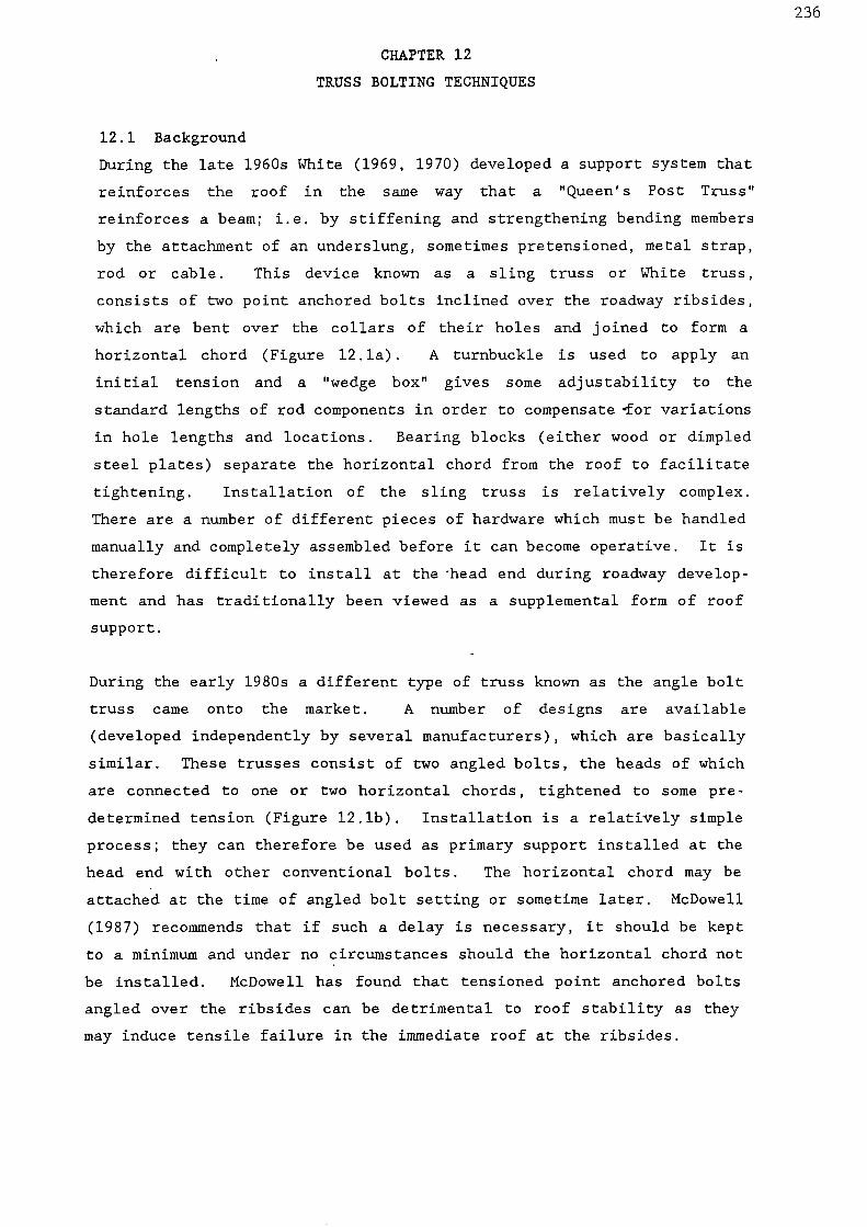
236
CHAPTER 12
TRUSS BOLTING TECHNIQUES
12.1 Background
During the late 1960s White (1969, 1970) developed a support system that
reinforces the roof in the same way that a "Queen's Post Truss"
reinforces a beam; i.e. by stiffening and strengthening bending members
by the attachment of an underslung, sometimes pretensioned, metal strap,
rod or cable. This device known as a sling truss or White truss,
consists of two point anchored bolts inclined over the roadway ribsides,
which are bent over the collars of their holes and joined to form a
horizontal chord (Figure 12.1a). A turnbuckle is used to apply an
initial tension and a "wedge box" gives some adjustability to the
standard lengths of rod components in order to compensate for variations
in hole lengths and locations. Bearing blocks (either wood or dimpled
steel plates) separate the horizontal chord from the roof to facilitate
tightening. Installation of the sling truss is relatively complex.
There are a number of different pieces of hardware which must be handled
manually and completely assembled before it can become operative. It is
therefore difficult to install at the head end during roadway develop-
ment and has traditionally been viewed as a supplemental form of roof
support.
During the early 1980s a different type of truss known as the angle bolt
truss came onto the market. A number of designs are available
(developed independently by several manufacturers), which are basically
similar. These trusses consist of two angled bolts, the heads of which
are connected to one or two horizontal chords, tightened to some pre-
determined tension (Figure 12.1b). Installation is a relatively simple
process; they can therefore be used as primary support installed at the
head end with other conventional bolts. The horizontal chord may be
attached at the time of angled bolt setting or sometime later. McDowell
(1987) recommends that if such a delay is necessary, it should be kept
to a minimum and under no circumstances should the horizontal chord not
be installed. McDowell has found that tensioned point anchored bolts
angled over the ribsides can be detrimental to roof stability as they
may induce tensile failure in the immediate roof at the ribsides.

ThreadedStud bolt Support
plateWoodenblock Coupling roof bolt
Turnbuckle
impasi.7====s MK.
45°
Resin PointAnchor
Angle Bolt
seki,F i at.
-=:
1.1= - - -
3.-2M1-nnn-n 4,111
Horizontal Extension Rod
Bearing Bracket..7.•n•n•nn••
237
Pointanchor
a. Sling type
b. Angle bolt type
Figure 12.1 Truss bolt systems.

238
12.2 Scale Model Studies
An attempt was made to simulate a sling type truss in a scale model
roadway. The model strata configuration used is given in Appendix la.
The chords were simulated by steel wire which was point anchored in a
section of electrical terminal block at the top of the angled holes.
The truss was tensioned by means of an extension spring (Figure 12.2)
stretched to simulate an applied tension of 50 kN (a force scale factor
of 1.14 x 10 -5 determined by dimensional analysis was used). The spring
was then covered with cyanoacrylate adhesive to prevent further
extension or relaxation. Two additional full column anchored bolts with
a 1.8 in equivalent length were installed in the centre of the rOadway.
The rows were set at an equivalent of 1 m centres.
The model was loaded hydrostatically. Figure 12.3 is a plot of per-
centage roof lowering against applied pressure, comparing the truss
bolted model with a model roadway supported by full column anchored
bolts with an identical configuration (Appendix 2d). The truss bolted
model suffered slightly less roof lowering at low applied pressures. At
a pressure of 0.56 MPa the roof began to deform and fracture due to
failure of the cyanoacrylate surrounding the spring. Therefore to
assist in establishing the effect of truss bolting under high stress
conditions the model truss will require some modification or redesign.
12.3 Limits Of Behaviour
Mangelsdorf (1986) has summarized his analysis of the support mechanisms
of the two truss bolt types. This has been reproduced below:
"The contribution of the truss to roof stability is a pair ofuplift forces at intermediate points between the ribs (Figure12.4). These forces (R) have vertical components equal to thevertical components of the inclined chord tensions. The horizontalcomponents of the uplift forces depend on the relative magnitudesof the horizontal chord tension and the horizontal components ofthe inclined chord tensions and on the extent of friction and/orbearing present. In the sling truss the horizontal component ofuplift is governed entirely by friction (Mangelsdorf 1980a) and atnormal friction levels is always towards the centre of the entry.In the angle-bolt truss the horizontal chord tension at instal-lation can be controlled to produce a near vertical uplift,although some inclination towards the centre of the entry may bedesirable as it may be offset later by increased inclined chordtension if the roof begins to work (Mangelsdorf 1982). Except inthe case of bed separation forming a very shallow roof beam, thehorizontal components of the uplift forces probably have a neg-ligible net direct influence on the support of the roof. It is thevertical uplift that is of primary importance.
Mangelsdorf (1980a) concluded that the transfer of tension fromthe horizontal chord to the inclined ones, or vice-versa, is mainlydue to frictional slippage of the bearing blocks. The contribution

Figure 12.2 Scale model of sling type truss bolt system

cr)cu• 'Cl,
r---+cu.H
• c• c
-a.f-13 S-1
04-)
UOD 0
CO
a)
• 1--13 0
-01 UCOO r-11-I 1-1
CO.1-1 -a4-4 4-)
O 3
cn(4-4 4-1o
a) am
Cl)CO cn
O 0sW .4
u
a) a)a. a.
0C1
Cl) CIDco a
•r-1OD 1-1• C/3
"1=1CU CU3 4-1O CI
r-1
L64 EO .r1O C13
4-1• 0
• 0O (l)
-r14-) $.4(0 (0
ECOO
u
a..
0
240
(%) DNivamo ri aoou

241
of friction to the installation and working life of trusses isdemonstrated in Figures 12.4. The lower and upper bounds of T/Hratio occur when the bearing block is slipping away and toward therib, respectively. Installation of the sling truss (Figure 12.4a)follows the path 0-1 with slipping of the bearing block or chordmaterial away from the rib as the horizontal chord is tightened.If, for some reason, H were then reduced without a correspondingdecrease in T, the truss would follow the path 1-2 until slippingbegan in the opposite direction, 2-3. If, on the other hand, theroof began to work causing an increase in T, the truss would followpath 1-4 until slipping began, 4-5.In angle bolt trusses (Figure 12.4b) a similar though not
identical postion prevails. Installation begins with tensioning ofthe angle bolt, path 0-1. The neck of the bolt bears against thecollar of the hole on the side nearest the rib. When the horiz-ontal chord is attached and tightened, the truss follows path 1-2.If it stops at 2 and then the roof begins to work, it will followthe path 2-3, and no slipping of the bearing bracket in eitherdirection takes place. If tightening follows the path 1-2-4-5,then some slipping occurs between 4 and 5. Subsequent loading willthen follow 5-6-7-8.In both systems tightening of the horizontal chord has a direct
effect on the tension of the inclined chord only if slipping takesplace. The ratio T/H remains essentially constant as does thedirection of the resultant uplift force R. Without slipping, suchtightening only changes the horizontal component of R. Thus,during tightening of the horizontal chord, either the magnitude ordirection of R will be changed, but not both.On the other hand, during loading, when the initial effect is an
increase in the inclined chord tension, R changes in both magnitudeand direction if slipping does not occur. Changes in H during thisincrease in R are generally quite small and are due to minor localdeformations in and around the bearing bracket or block and tobending strain in the roof surface which is also quite small exceptin very shallow roof beams. If slipping does occur, only themagnitude of R changes."
12.4 Optimum Design Of Roof Truss Installations
White (1967) assumed that compression stresses in the rock radiated from
the anchors and bearing blocks along lines corresponding to the members
of a conventional truss (Figure 12.5). A later analysis (Cox and White
1977) suggested that either suspension or reinforced rock arch action
occuring below a pressure or ground arch, may account for the behaviour
of trusses.
Scientists , at the Central Mining Research Station in India have produced
a statical analysis of the sling truss (Raju et al 1972, Sheorey et al
1973). The notation used in this analysis is given in Figure 12.6.
Resolving the forces along and perpendicular to the direction of applied
tension (T) and taking moments about the point where the truss touches
the borehole edge (B), gives:
T - ihR2 - Rising - Pcosa — 0R2 + Ricosa - Psina 0
R2(a + L) + mR2b - Tb 0

242
•.••••n
CO
\v—I
0
7:3
Cr)
a)
aco
Cat4-1
Cr)a)cr)cn
4.J
00S-1
0
0•
4-1
171
0
Ca1-)
Cn
CO
S-1
00
Ca
.H
'1=1
a)
1 Hog paupui uo.suel
I • oa peuuoui u uo!sual

'
r '" 1 1
' I i '
...00........,... .,.. ,...,....... ...,..... --,-.....,e,-,....,.., 'rel.? .... •-•.-ii-r-r 7 (-0*Fr "Tr7 TrTr
,,,,,,-- . ,..-.• .C...‘,.--, i ' i •-,,,,,---, --.�1.•:::.;,:•:‘, ,--
s-,. •'-i.,Ae.'`..`',` . \ ' \ ''''.
'tekftV7
• 0,4r,•••4
1111131�44.
• 4.
kiT,,4414,
.440,
Tension in Ihe steel rodsproduces Compression inOil Shaded urrO.
243
Figure 12.5 Assumed pressure distribution for a fully active slingtruss.
Figure 12.6 Statics of a roof truss (after Sheorey et al 1973).

244
Solving these equations simultaneously with respect to T, gives:P T [(a + L)cosa + bsina]
pb + a + L
Ri T [(a + L)sina + bcosa]pb + a + L
R2= Tb
pb + a + LIf the bearing block is positioned close to the borehole mouth so that
the truss does not touch the roof rock, eliminating a reaction at the
mouth of the hole (Ri — 0), then:
T - pR2 PcosaR2 — PsinaP=
cosa + psinaR2=
p + cosaa tan
a+ L
Where P — load on the anchorage of the boltT — tensioning load on the truss
Ri — reaction at the mouth of the holeR2 — reaction at the block
L — distance from the block to the hole2a — width of blockb — thickness of the blockp — coefficient of friction between the block and the roof rocka — angle of inclination of the hole
Several assumptions have been made in this analysis, namely that:
(i) the truss chord follows an arch in the vicinity of the borehole
mouth, in practice angular kinks occur where the truss contacts the
rock and the bearing block;
(ii) friction occurs at the block but not at the borehole mouth and only
one magnitude of friction coefficient was considered;
(iii) no displacement occurs at the borehole mouth or above the bearing
blocks.
The analysis also takes no account of:
(i) any reaction perpendicular to the rod at the anchorage point;
(ii) any movement about this point;
(iii) the rigidity of the steel used.
Hodkin (1975) has produced a more detailed analysis taking these factors
into account but continuing to make the same assumptions. The
improvement in accuracy obtained is relatively small, so for practical
purposes the Indian analysis is generally sufficient.
Neall et al (1976, 1978, 1981) have carried out photoelastic model
studies with scaled trusses based on the beam reinforcement concept. The

245
study concluded that the optimum angle for inclined chord installation is
between 45 0 and 60 0 . This was confirmed by Khair (1983). Neall et al
also found that more effective support could be achieved by moving the
holes closer towards one another; but only at the expense of longer holes
if the anchorage over the rib is to be maintained. These tests were
carried out using only one roof span and only one truss span; there was
also considerable scatter of the data.
According to Seegmiller (1980), in a rectangular roadway with a width to
height ratio of 2 and roof rock with a Poisson's ratio of 0.25, the
tensile-compressive equivalence points occur approximately at a distance
of 3/10 of the roof span from the centre of the span toward the rib
(Figure 12.7). Seegmiller recommends that a truss bolt system should be
placed to maximize the support force in the tensile zone while still
maintaining effective anchorage in the roof. The optimum position of the
angled bolt would be at the point where the stresses change from tensile
to compressive. This translation point will be a function of the roof
span and opening height. In roadways with width to height ratios between
2 and 3, the preferred angled bolt location would be at the edge of the
central 60 to 65% of the opening.
Locotos (1987) recommends that the distance from the rib to the angled
bolt hole collar should be 1/5 the entry width, and should not exceed
1.2 m. Locotos uses the following formula to determine the angled bolt
length (Lrb ) :
Lrb /2[(r - s) + 1.5]2where r — distance from centre line to hole location
s — half maximium entry widthThis ensures that the bolt is anchored 0.45 m into the ribside pillar.
Mangelsdorf (1985a, 1987a) has shown that by minimizing bending strain
energy it is possible to optimize inclined chord location and tensions
for roof trusses.
To Determine Bolt Angle (9):
(i) Calculate angle bolt tension (fi)2T/wL
where T — installed chord tensionL — width of roadwayw — load acting on roof truss system
(ii) Calculate aspect ratio (9/A)
where A — ratio of free anchor length to roadway widtht/L
t — free anchor length of angled bolt

246
5
0117. 4
cc3
2
01
0=
COMPeeSSIVETENSILE
Figure 12.7 Approximate boundary stress conditions in a rectangularopening (after Seegmiller 1986).
60
50
40
30
-0
20
10
0.5
.4
.3
.2
1
1
I I II
t Ill 1
1
104 0.6 0.8 1 2
3/X
4 6
Figure 12.8 Optimum slope for angle bolts based on bending strainenergy (after Mangelsdorf 1987a).

247
(iii) Consult Figure 12.8 to find optimum slope for angled bolts (0).
To Determine Position Of Mouth Of Angled Bolt Hole From Rib (a):
(i) Calculate the ratio (a) of the distance from the rib to the
position of the angled hole (a) to the roadway width (L)
a a/L
Therefore
a — aL
12.5 Monitoring
Electrical strain gauges attached to the chords are probably the most
direct means of measuring chord tensions, although this will become
expensive if a large number of trusses are to be observed.
Mangelsdorf (1980b, 1983, 1985b) has developed a portable, battery
operated instrument which measures the natural frequency of vibration of
the horizontal chord. It is then possible to calculate the chord tension
from a calibration formula. Further evaluation and development of this
technique is currently being undertaken by staff at the USBM Spokane
Research Center.
12.6 Application Of Sling Type Trusses
A number of articles were published during the late 1960s and through the
1970s reporting successes of sling type truss installations (Anon 1969;
Kegel 1969; Kmetz 1970; Raju et al 1972; Mallicoat 1978; Beadnall 1978;
NCB 1978; NCB 1980; Round 1979; Mangelsdorf 1979a). Tensioning of sling
trusses has been known to lift the roof strata clear off wooden standing
support installed in roadways (Kmetz 1969; Raju et al 1972).
A decline in the use of these trusses occurred towards the end of the
1970s due to a lack of proper installation equipment, the relative
expense of the hardware, a few explained and unexplained failures, and
the emergence of resin rock bolting as a cheaper and faster alternative
support for difficult roof conditions.
The most recent sling truss installation in the UK was at Thoresby
Colliery in 1985 for 103's retreat face which worked the Parkgate Seam at
a depth of 750 m. The main gate was supported by flat topped supports
4.90 x 2.61 m (152 x 127 mm section) set at 1 m intervals with nine heavy
duty tubular struts per setting. The roadway was driven some 6 m away
from the disused 101's loader gate. In the vicinity of 103's, the

248
Parkgate Seam is overlain by approximately 1 m of weak laminated planty
mudstone which grades into a stronger fine poorly laminated siltstone,
containing ironstone nodules, lenses and bands.
Although standards of work were very good it was found necessary to
install wooden middle legs along the length of the roadway. Before
production had commenced some of the roof beams became deformed. This
was probably the result of an inadequate size of pillar between the
roadway and 101's workings.
Before face retreat had commenced, sling type truss bolts were installed
in two sections of the main gate in addition to the existing steel
standing supports. The inclined chords were 2.44 m long, angled at 450
over the ribsides and anchored with resin. Fourteen trusses were set in
each section between the steel work. The installation was problematical
as the roof was completely sheeted over with corregated lagging.
Monitoring stations were located in a truss bolted section and a section
with standing support only, in order to establish the effect of truss
bolting on roadway stability as the retreating face approached. The
closures and support loading measured (Figure 12.9a and b) showed that no
significant benefits were gained from truss bolting; considerable roadway
closure and support loading occurred in both sections. The truss bolts
were not able to prevent roof rock beam buckling and displacement due to
mining induced stress from the front abutment of 103's and the ribside
abutment of 101's faces.
12.7 Application Of Single Bar Angle Bolt Trusses: Tensioned At Blocks
It was stated earlier that a number of different designs of angled bar
trusses have been produced. The most successful of these are single bar
trusses with a low profile against the roof, a strong bearing block and
flexibility/tolerence on placement of the angled holes. The induced and
horizontal chords must be in the same plane, otherwise rotation of the
block will occur during tensioning and loading, which will lead to
tearing of the bracket and bar threads.
Two popular designs were observed in use at the Jane Mine in
Pennsylvania, USA. The mine is working the Lower Freeport Seam by room
and pillar mining at a depth of 70 to 140 m and with a mineable section
of 1.75 m. Overlying the seam is a dark grey mudstone with sandstone
laminae and layers which vary from a few millimeters to 350 mm in

Z•..:g
50
-,O 40
.4
30E-
O 20a..a.• 10(40
o150 050100 25
- 800 ....e,...,
- 700 >
....- 600 -t.'
>n..'
- 500 -n
- 400 t-0cA
- 300 C
- 200 r-1
- -2- '- 100
,........
0
--.---s-- Vertical closure---0---0-- Horizontal closure-1----1-- Standing support loading
8007:1e.
.- 7 0 0 Z
=600
>.500 .....:
n400
C)
- 300 CID
N
200 rfl
100
0
2.‘-'4".• 50 -CI-•!CO 40 -
)..430 -
4O 20 -P.1P.I• 10 '
(ID
0
249
DISTANCE OUTBYE OF 103's RETREATING FACE
a. Section without truss bolts
150 100 50 25
0
DISTANCE OUTBYE OF 103's RETREATING FACE
b. Section with truss bolts as an additional support
Figure 12.9 Convergence and support loading recorded in 103's main gate,
Thoresby Colliery.

250thickness. Areas of the mine with a high proportion of these laminae and
layers tend to suffer roof stability problems.
Limited success was achieved in controlling unstable roof by the use of
timber, 152 mm section I-beams, 3 m long coupled resin grouted bolts and
point anchored resin grouted expansion shell bolts used in combinations.
In addition the main drivages were altered to a more favourable
direction. However, mining progress was slow and major roof falls
usually 6 to 7.5 m high were still occurring.
The first truss system to be installed in the mine was produced by Pattin
Manufacturing Co. It consists of a coupled bar which is connected to the
inclined chords at a three-hole block and U-bolt (Figure 12.10). The use
of this system in the mine has been described by Barish (1985a, 1985b).
The 152 x 152 x 8 mm bearing plates tended to distort and were being
pulled into the roof. The plate size was increased to a 203 x 203 x
19 mm plate; the additional bearing surface against the roof alleviated
this problem.
Due to the large number of moveable parts inherent in the U-bolt system,
a simpler truss marketed by Jennmar Corp. is now being employed at the
mine. It has cast ductile iron blocks with a bearing surface of 0.042 m2
(Figure 12.11) which are quick to install and can withstand loads in
excess of 200 kN. The smaller number of moveable parts means that less
friction is encountered during the tensioning operation. Consequently
the Jennmar system only requires 237 Nm of torque to achieve a tension of
63 kN whereas the Pattin system requires 271 Nm of torque to achieve
62 kN tension.
The trusses are installed in-cycle at the head end with two 1.8 m
vertical point anchored grouted expansion shell bolts at 0.9 to 1.5 m
centres depending on ground conditions. The 2.1 m long, 19 mm diameter
angled bolts are also fixed by a dual resin/expansion shell anchor with a
minimum grout length of 0.6 m. The angled bolt hole is drilled at 450,
0.6 to 0.9 m from the ribside.
Truss bolting has made a tremendous difference to the mine. Management
maintain that the mine would not have been able to remain competitive
without them. The use of beams, wooden cross bars and support legs has
been eliminated. In addition to improved strata control, ventilation and
transportation expenses, fewer accidents are now occurring as the mine

U bolt Couper
cOosa),===C:14.,+—o/ 5
..Val-15. 1/, a 10. - CD
1/, ICAVY ICC 10:T3vtITN MAX .411-n1.5
TO COuelal
4-1/2.
MIME'
1111111A1111
251
1.83 m lcng bolts
Figure 12.10 Pattin truss installed at Jane Mine.
Figure 12.11 Jennmar truss installed at Jane Mine.

252
workers no longer handle large amounts of extremely heavy, bulky
material.
12.8 Application Of Single Bar Angle Bolt Trusses: Wedge-Box Tensioned
The Birmingham Bolt Co., in association with Peabody Coal Co. have
developed an angle bolt truss system. The stages of development from the
sling truss to the hydraulically tensioned angled bolt truss currently in
use was observed at Peabody's Camp No.2 Mine in Kentucky, USA. The mine
works the Kentucky No.9 Seam by room and pillar mining. The entries are
6.1 m wide and 1.7 m high, totally in-seam. The workings lie at a depth
of between 120 and 140 m. The pillars are at 21 to 24 m centres, this
varies depending on the overburden.
The immediate roof consists of a dark grey mudstone which gradually
weathers and becomes unstable. The installation of truss bolts has
reduced this instability problem in the belt and track entries. Two
vertical 1.8 m long resin point anchored bolts are installed across the
roadway with each truss setting (i.e. at 1.5 m intervals). The inclined
chords are 2.44 m long, bendable and point anchored with a 0.9 m grout
length. The inclined hole collars are positioned 1.2 m from the ribside.
The turnbuckle/pipe wrench tensioned sling type truss initially used was
replaced by a hydraulically tensioned sling truss with a modified wedge
box (Figure 12.12). The development of the hydraulic torque tensioning
wrench for truss bolting has been described by Bollier (1982). The tool
is capable of applying a uniform tension in every truss, reducing
installation time, reducing difficulties in tensioning a truss and
providing a method of testing the installed load. The sling has a total
length of 8.2 m. If one side of this truss is heavily loaded, the
bearing block tends to slip and transfer load to the other side; this is
an advantage over the angled bolt truss. However, bearing block slip
during .tensioning became a problem, consequently a modified plate was
used with a notch to grip the roof and prevent slip.
The first angled bolt truss to be installed in the mine had a rigid angle
of 45 0 only, the bolt being fixed to the bearing block by a cotter pin.
The rigid angle gives obvious limitations to bolt installation; strain
induced in the angled bolts caused a few to break just above the flange.
Thus a flexible angled bolt truss was developed. The bolts consist of a
19 mm diameter rod made from high strength Grade 75 steel. The holes are

253
drilled in two stages; initially with a 38.1 mm or 41.3 mm bit, then a
34.5 mm bit. This type of truss can be installed extremely rapidly.
When the angled bolts have been anchored, one of the two sections of the
cross bar is inserted into each bearing block (the bars have a T-shaped
end to hold it in place, i.e. no nuts are required to secure the cross
bar to the blocks). A screw coupler is fixed to the cross bar at one
end. Both sections of the cross bar are then inserted into a wedge-box.
A nut is screwed onto the threaded rod and then 200 to 230 Mm of torque
is applied with a hydraulic torque wrench. The wrench is equipped with
an adjustable automatic pressure relief valve, allowing the device to be
pre-set to any desired torque or tension range. The wedge-box gives
450 mm of flexibility in angle hole location. The only failure of this
type of truss to-date is a fracture at the T-head of one bar during
installation.
12.9 Application Of Double Bar Angle Bolt Trusses
Angle bolt trusses with two cross bars which are tensioned at the blocks
have recently come onto the market (Figure 12.13). These bolts are
generally used under high loading conditions.
A post-development installation of a double tie angle bolt truss system
has been successful in preventing excessive roof lowering in a gateroad
serving a retreating longwall face at Bailey Mine, Pennsylvania, USA
(Locotos 1987). The mine is working the 1.5 m thick Pittsburgh Seam with
150 m long panels. Three or four entries serve each end of the faces.
The entries are 5.5 m wide and between 1.7 and 2.0 m high. The seam is
overlain by 0.3 to 0.45 m of draw slate, 0.3 m of roof coal and 1.8 to
2.1 m of slickenslided laminated mudstone. Above these beds there is a
massive sandstone.
The primary support for the entries consists of rows of four 19 mm
diameter, 2.44 m long fully resin grouted rock bolts installed in a 25 mm
diameter hole through a 5.2 m long (76 x 203 mm section) wooden plank at
1.2 m centres.
Truss bolts were installed at least 20 m in front of a face line which
resulted in a considerable improvement in the face end conditions.
Initially some of the angled bolt brackets failed. Recent modifications
have strengthened the plate and solved this problem.
Mangelsdorf (1987b) has expressed doubts concerning the necessity for

1•114011
-
Figure 12.12 Truss wedge tensioner (after Bollier 1982).
/ROOF BOLT
TRUSS BRACKET
HORIZONTAL TIE Roo -,4
.../—RESIN ANCHORAGE
_...ClowtooMWA
254
Figure 12.13 Double bar angle bolt truss.

255
double cross bars. He maintains that the tension in the angled bolts is
always greater than in the horizontal chord, therefore unless the
individual ties are significantly weaker than the angled bolts, there is
no need for double ties. In addition, considerable care must be taken
when installing double tie bar trusses; in order to avoid uneven
tensioning and rotation of the brackets, each bar must be tightened and
then retightened during the installation process. Also the additional
steel, hardware and installation time increases the cost of these
systems.
12.10 Recent Developments
A four-way truss bracket for use in the centre of double bar angle bolt
trusses has been devised by Seegmiller (1987). The trusses are designed
for support of mine intersections (Figure 12.14) or to provide additional
support along the length of an entry (Figure 12.15).
The successful use of this truss system in three-way and four-way
junctions at Deserado Mine in Colorado, USA, has been described by Adams
(1987). The central bracket is installed initially and the adjoining tie
bars are then tensioned in rotation to avoid excessive side loading on
the central vertical bolt.
A trial has recently been initiated involving the post development truss
bolt reinforcement of the tail gate of K14's retreat face in the Brass
Thill Seam at Ellington Colliery. This is the first use of angle bolt
trusses in the UK. Trusses (both single and double tie bar types) have
been installed in the 5.5 to 6.1 m wide roadway between existing standing
support (consisting of wooden legs and steel RSJs 127 x 114 mm cross
members at 1 m intervals). It is intended to monitor the performance of
these trusses during face retreat.

256
,wAYINTERSECTIONS
II
II
Figure 12.14 Intersection truss (after Seegmiller 1987).
Figure 12.15 Continuous entry truss (after Seegmiller 1987).

257
CHAPTER 13
EXTENDED GROUND SUPPORT
13.1 Background
Extended ground support refers to long anchorages installed in an
excavation to stabilize large volumes of rock. This type of support
permits reinforcement of rock failure occurring at greater distances
from the opening than standard rock bolts. Applications are generally
limited to locations of high potential instability such as weak strata
at depth, fault zones and junctions.
Extended ground support can be achieved by a variety of devices ranging
in complexity from simple coupled bolts and cable bolts to sophisticated
rock anchors. They can be fully bonded or have a tensioned free length.
The use of extended ground support in the form of coupled bolts for
floor reinforcement has been discussed in Chapter 11. Rock anchors are
expensive and their use in underground excavations is limited to civil
engineering projects. Cable bolts consist of high tensile steel cables
which are usually fully bonded with injected inorganic grout. Some
typical cable bolts are illustrated in Figure 13.1.
13.2 Axial Loading Characteristics Of Cable Bolts
Axial loading characteristics of various types of cable bolt stands are
currently under evaluation at the USBM Spokane Reseach Center (Goris and
Conway 1987). Pull tests have been conducted on sections of cable
embedded in 254 mm of cement grout. After 28 days, all the cables tested
could support maximium loads of at least 77.8 kN and showed good
residual load carrying capacity.
Epoxy coated strands with embedded grit showed an increased load
carrying capacity of approximately 31% over conventional strands (Figure
13.2a). Epoxy coated strands were originally produced for use in pre-
stressed concrete members. The 0.76 mm thick coat provides corrosion
resistance while the embedded grit increases frictional resistance.
During the tests the bond between the coating and the strand remained
intact. The increase in the load carrying capacity of the epoxy
coating, together with its chemical resistance, makes this type of
strand very attractive for long-term use in cable bolt support systems.
However, the cost of the epoxy coated strand is approximately twice that
of bare strand.

258
cnCl)
6- - 0 45CL) CL E .o c
.E
_C 73
2al '
u) co.cti.7 .o 'a)
(7," 7:j °- E -...--. < ET) 75 co 0Z
.=CI> 0 co (1) c E.L._ -0 ..., cd o -0 __z -0
cr) a) 1/4,;-;.-E-3 s E
c CD • — LC1-) -Cicti a).73— E5 o
N. ._, co u) E --0 E 0- -0c o 0
cn CD Q)0t.- CD
. ai 0.9 (1) (DoL._ c\J 13 d- CZ 2 Eo_ cc
-0 _ct _c -CI-0 0
• 01 0°E
-a •
NJ C ZE .-- -FD
T T
. (7 2 t2 8 E -- -a _c --- L._ ._ 0 '-. o
NEE c c.) cz a) c. /5 o crCl) CD
l()2 15-CD 0 a)
6 Z c\ic) Eci) ..c ) _in o Eg -
- o E -o -a c 4-. 0D
1:3 ir) ' 0 c .— a) c) 0 10 Ec •c7i El/ 0 -0 00 coas a 0 Lis E 2
(11 .-- E 0 in
-,71 cCci)
.
•Ti; 0) cu 73 a. ›..,
73
-0 (r) CD0) Ow ID E 0 ca) a)a) . —c E o) c N'i
cp (1) -C (.1) Cr.ce E 77: E
z
c
,..,-- o
C.o U)
CLI - — ' (n—o _Y
c .—-0 a) 2; .Z -0 03 a)
o'-' (-) ,.._ 1.n N
%-. CI)- --
0al L- -5
C-n- 22 _1(1) 4=4-- a ci.: 2 Ea .. cz *(7) .. _c
Cd
6

259
The resistance to pull out developed by a grouted strand is due
initially to the mechanical interlock along the grout-strand interface.
Once slippage begins, pull out resistance is due to friction along this
interface. One method of increasing pull out resistance is to add a
bearing surface inside the grout column perpendicular to the axis of the
strand, thereby transferring the load between the strand and the grout
by compression of the grout. This can be accomplished in various ways,
such as attaching a stressing anchor to the strand or by pressing a
thick wall sleeve onto the strand. One such device in use is referred
to as a steel button. The buttons are generally 25 to 32 mm in diameter
and 38 to 45 mm long. Preliminary tests reported by Cons and Conway
(1987) have shown that buttons have potential for increasing the load
carrying capacity of cable bolts over conventional strands by as much as
219%. Although it appears that the location of the button within the
grout column will greatly influence the pull out resistance of the
system (Figure 13.2b). It must therefore be ensured that the buttons
are placed in the proper location i.e. at least 50 mm from the back end
of the hole and any discontinuity. This is obviously a difficult task
and consequently could be a major disadvantage to their use.
A recent development for the Australian mining industry is the birdcage
cable bolt. Nodes are made along a cable strand by separating the seven
wires of a conventional strand, rotating the outer six wires slightly
and then recombining the wires to form an open strand where the surface
area of all the wires comes in contact with the grout.
The behaviour of this bolt under load is influenced by many factors, an
important one being the location of the node with respect to rock
discontinuities. Cons and Conway (1987) have reported two pull tests
on birdcage bolts: Series I with an antinode located at the top of the
embedded length and Series II with a node located at the top of the
embedded length (Figure 13.2c). The load-displacement curve for the two
series are similar in shape (Figure 13.2d); however, the average maximum
load achieved by the Series II samples is approximately 24% lower than
for Series I. There was a loss of grout column on the Series II cables
in the region "A" on Figure 13.2c because the wires in this region were
deflected toward the centre due to tensile load. The grout surrounding
the wires became highly fractured and offered little or no resistance to
pull. This phenomenon did not occur with Series I samples. The two
main peaks in the Series I load-displacement curve correlates with the

250
200 KEY102-mm
150 embedment _
< 1 00
— 51—mm
embedment _0 Conventional
50
KEY— Series I-- Series II— Conventional
Series Series//
Pipe
560 mm
180 mm
254 mm
Birdcagestrand
Pipe j unction—
Node—Anti — node—
Series II
after testing
Region A
180 mm
57 mm
260
100
Z 75
0 50
0—J 25
25 50 75 100 125 150 175
DISPLACEMENT, mm
I 1 1 I I
o 25 50 75 100 125 150
DISPLACEMENT, mm
a. Results for epoxy-coated strand b. Results for samples with steelbuttons
c. Samples with birdcage strand
175
150
Z 125
_100
< 75
50
25
0 25 50 75 100 125 150 175
DISPLACEMENT, mm
d. Results for birdcage strand
Figure 13.2 Cable bolt pull tests (after Goris & Conway 1987).

261
spacing of the nodes. To date, the test data accumulated shows that the
maximum load carrying capacity of the birdcage bolt was between 47% and
94% higher than that of bolts with a conventional strand.
The grout used in the above tests was made from Type I cement and had a
water-cement ratio of 0.45 to 1.0. It has become apparent from a study
of this grout that water bleeding by capillary action will result in
collection of water at the top of the hole. Depths of water measured
were approximately 25 mm per 300 mm of grout (Brady 1987). Water
bleeding is therefore an important consideration when designing cable
bolt lengths.
13.3 Cable Bolt Applications
Principal applications of cable bolts in the past have been for metal-
iferrous mining in cut-and-fill, open stoping and block caving
operations. Details of cable bolts used in some of these mines are
given in Table 13.1.
Cable bolts have been installed in junctions and longwall gateroads of
some Australian coal mines. The first of these trials was successfully
completed at Tahmoor Colliery, New South Wales, in 1983. This technique
is still in the development stage but it is considered by some
Australian strata control engineers to be especially useful in areas of
high stress.
Singh et al (1986) describe a method of depillaring in a 6.5 to 8 m
thick seam at New Chirimiri Ponri Mine, India. Cable bolts with a
diameter of 22 mm were anchored with injected cement grout through
approximately 3.5 m of roof coal to at least 1.5 m within the sandstone
roof. The roof coal was blasted down, leaving 1.5 m of bolt which
maintained a stable roof during coal gathering operations. This system
improved recovery by up to 70%.
13.4 Swellex Long Rock Bolt
According to the manufacturers (Atlas Copco 1985) flexible Swellex bolts
up to 9 m long can be installed in head-rooms as low as 2.75 m. The
standard Swellex is described in detail in Section 14.3. Long Swellex
bolts are highly cost competitive compared with other extended ground
support systems. They are cheaper than coupled rebars, do not require
grouting and are quickly installed. The manufacturers quote an under-

262
MINE METHOD CABLE DIAMETER
(mm)
CABLES PER HOLE HOLE DIAMETER
(mm)
LENGTH
(m)
REFERENCES
New Broken Hitt,
Australia
Cut & Fill 15.2_
2 65 20 Hunt & Askew
(1977)
Con, Canada Cut & Fill ' 15.9 2 57 9 - 21 Cassidy (1980)
Tsumeb, Namibia Cut & Fill 24.0 1 57 21 Stheeman (1982)
Myra, Canada Cut & Fill • 15.9 2 51 15 Walker (1986)
MaLmberget,
Sweden
Open Stoping 36.0 1 N/K 15 - 25 Setlden (1983)
Kotatahi, Fintand Open Stoping 15.2 2 41 - 64 6 - 50 Lappalainen et al
(1983)
San Manuel, USA Block Caving 15.2 1 38 10 - 23 Stevens et al
(1987)
i
Table 13.1 Details of cable bolts used in metalliferrous mining.

263
ground installation of a 7.3 m long Swellex bolt where the drilling for
the 38 mm diameter hole was 8 minutes and it took two men just 3 minutes
to insert and inflate the bolt.
To date, applications of these bolts have primarily been limited to the
reinforcement of drifts ending in open stopes, where the change to large
diameter blast holes has created stability problems. At Westcliffe
Colliery, Australia, 7.3 m long Swellex bolts have been used in a fall
recovery operation to secure the front wall and as forepoles from the
tailgate (Pugh et al 1987).
13.5 Extended Ground Support Design
There is no reliable quantitative design method available to determine
the optimum spacing of extended ground support systems because the
distribution of loading along the anchorages cannot be accurately
predicted. Consequently bolt spacing is generally chosen empirically.
The Finnish, Outokumpu Oy Mining Company use finite and boundary element
methods of calculation qualitatively for cable bolting to locate the
most critical zones to be reinforced.

264
CHAPTER 14
ALTERNATIVE ROCK BOLTING SYSTEMS
14.1 Background
During the last fifteen years several different rock bolting systems
have been devised including yielding bolts, friction bolts and a number
of systems utilizing a variety of types of rod and anchorage. A few of
these have found applications in mine roadway support systems.
The so called "friction rock bolts" (eg Split Set and Swellex) are
widely used in hardrock mining operations. If these bolts are to be
classified together a better descriptive term would be "full column
mechanical anchored bolts" as all other types of rock bolt also offer
some form of frictional resistance.
14.2 Yielding Rock Bolts
The stiffness of grouted rock bolt systems offers good restraint to
slowly increasing stresses. Where rapid stress changes occur at a
fracture plane in a bolted strata zone or where a weak bed in pre-
dominately strong bolted strata is undergoing rapid failure, elastic
rupture of the grout and steel may take place. Under these circum-
stances a yielding bolt may be beneficial to relieve these stresses and
then take up strength once more in a new state of equilibrium.
Some simple concepts of yielding bolts designed to cope with excessive
rock deformation resulting from seismic activity in the South African
mining industry are illustrated in Figure 14.1.
A yielding bolt developed by the USBM (Conway et al 1975, 1977) did not
prove entirely successful. The yielding effect was achieved by a smooth
bore die fitted to a bolt at the borehole opening. Consequently, it was
not very effective with fully grouted rebar when the bolt was stressed
deeper in the borehole (Reuther and Hermulhein 1985).
Some yielding bolt concepts have been developed for use in the German
coal mining industry (Grotowsky 1981; Baur and Brune 1984; Gotze 1986;
Stephan 1987). The "kombi anker" is one such device (Figure 14.2) which
has a high load-bearing peak but is also highly ductile; i.e. it
combines the function of a rigid bolt with that of a tensile or yielding
bolt. The ductile inner core of these bolts is pre-tensioned against an

a) Kinked Car
b) Soft point anchor
Yieldmggmw
Yielding piece
600600
—400400
I.
2001L 200
00 100 200 300Traction Path (mm)
Abutment
100 200
300Shear Path (me)
265
Before
Afterdiscontinuity
discontinuityseparation separation
al Straightened bar
N Anchorage point displaced
N Grout/bar debonded toallow bar stretch
Figure 14.1 Some concepts of yielding rock bolts (after Moore &Noyons 1986).
150 Steel sleeve Rod core
Figure 14.2 Load bearing and deformation behaviour of a kombl boitwith a length of yield of 150 mm (after Stephan 1198-n,

266outer sleeve, the extent of which determines the load bearing peak of
the bolt. The core and sleeve act together to prevent initial rock
deformation. At high stresses, the outer sleeve tears off and the
section of core that protrudes into the roadway is drawn into the
borehole, permitting considerable axial and shear deformation without
failure.
The debondable bolt (Daws 1978, 1980b) has similarities to the kombi
anker. A core of high strength steel, threaded at one end and with a
cylindrical block at the other, is surrounded by a series of high
density polyethylene sleeves. The sleeves debond under load, permitting
controlled deformation to occur
14.3 Split Set Rock Bolts
The Split Set rock bolt was invented by J.J. Scott in 1973, developed by
Ingersoll-Rand Co. and introduced into the US mining industry in 1977.
The bolt is manufactured from a 2.3 mm thick hot rolled low alloy steel
sheet that is formed into a tube with a 16 mm diameter longitudinal
slot. The tubes are cut to specific lengths; a taper is shaped at one
end and a ring flange is welded to the other end to support the bearing
plate. During installation the bolt is driven into a slightly under-
sized borehole. The slot permits compression of the tube but does not
close completely so that a radial force is applied against the rock
along its contact length (Figure 14.3). -Split Sets are available with
nominal outer tube diameters of 33 mm, 39 mm and 46 mm. Standard Split
Set lengths range between 0.9 m and 3.7 m.
Split Set bolts require precussive or vibrating insertion equipment.
The anchorage obtained during installation is dependent on the degree of
interference. This is defined by Scott (1976) as "the difference in
diameter between the manufactured Split Set and the borehole in which it
is placed. It also includes anchorage obtained due to the frictional
coefficient, borehole deviation, borehole rifling, broken ground etc".
According to the manufacturer, an initial anchorage of between 30-60 kN
for the 33 and 39 mm bolts, and 50-90 kN for the 46 mm bolt should be
achieved. The drilling parameters required to attain this will vary
from site to site and should be determined by a series of pull tests.
The tests should be carried out on bolts installed in holes drilled with
bits 1 to 5 mm smaller than the outer diameter of the Split Set. Each
hole must be at least 50 mm longer than the bolt. The sensitivity of

267Split Set performance to hole diameter can be a major draw back with
this system.
Scott (1978, 1980a) states that Split Sets act over their entire contact
length and thus prevent the formation of any large stress concentrations
to creep or bleed off with time. However, the method of insertion will
cause the Split Set to take the shape of the smallest diameter of the
borehole which in certain circumstances could limit the percentage of
good contact. In fractured or laminated strata, the loosening of rock
fragments inside the hole during bolt installation may impede borehole
wall contact. Poisalo (1983) overcored some Split Sets and found these
bolts to be only partly in contact with the borehole. This character-
istic will result in variable pull test results and tend to make the
bolts flexible and deformable.
In addition to the radial forces, an axial confinement load is also
produced during installation. Plate loads of 30-40 kN have been
recorded (Scott 1980b; Chaiko and Scott 1977).
The yieldable aspects of Split Set bolts, without loss of restraint
against the rock, are emphasized by the manufacturers (Bronder 1986).
Pull tests have shown that the load-bearing capacity of Split Sets can
increase with time (Scott 1976; Chaiko and Scott 1977; Scott 1977; Scott
and Jackson 1977; Scott 1980; Croizat et al 1982; Liangkui and Shendou
1983; Scott 1983). The increase in anchorage is due to slight corrosion
of the bolt surface and a higher radial tension caused by deformation of
the surrounding strata. The tests also indicate that the bolt is
capable of sliding as a unit within the borehole as bed separation
occurs, without losing anchorage along its contact length. Failure of
the bolt end ring can occur with continued roof dilation causing plate
contact to be lost. Ring detachment will give an early warning of a
potential roof failure.
Shear tests carried out by Haas et al (1978) have concluded that Split
Sets are capable of withstanding large deformations while still
resisting shearing.
The use of Split Sets in coal mining has been limited to date, although
a monitoring programme at a trial in an Australian Colliery found that
they provided a comparable support to resin anchored roof bolts
(Richmond and Hebblewhite 1980).

Figure 14.3 Split Set bolt.
VECTORS INDICATE SPuT SET ANDPLATE FORCES AGAINST ROCK
ROOF PLATE
RETAINING RING.
268
Washer Plate
Water •Injection Hole
Figure 14.4 Swellex bolt.
269
14.4 Swellex Rock Bolts
The Swellex rock bolt (also called "Webster Rockfast") has been
developed by Atlas Copco. The bolt is manufactured from a steel tube
2 mm thick with a 41 mm outer diameter that is cold rolled and reshaped
to form a folded profile 25.5 mm in diameter. Short support sleeves
(bushings) are pressed onto the ends and sealed by welding. The bottom
bushing is more sturdy and flanged to retain a bearing plate. The bolt
is installed in a borehole by injecting water from a high pressure pump
(at 20-30 MPa) into a small hole drilled in the lower bushing. The
water expands the bolt so that it conforms to the profile of the hole
(Figure 14.4). Only 2 L of water are required per 1.8 m bolt length.
During the swelling process the bolt shortens along its vertical axis
and pulls the bearing plate against the rock surface, exerting an axial
load of up to 15 kN. When the water injection chuck is held manually
difficulties can be encountered in keeping the plate tight to the rock
to obtain pre-tension (Oram 1986). The pump automatically stops at a
pre-set pressure and the water drains out of the bolt. During Swellex
trials for a face salvage operation at Kellingley Colliery, 38 mm drill
bits were found to be producing over sized holes in weak strata at the
mouth of the hole. The installed bolt ends appeared to be almost fully
expanded which may have resulted in a reduction of the residual pressure
between the bolt and the hole wall. Expansion of the bolt end outside
the borehole can loosen pieces of rock at the borehole'mouth. This can
be prevented by fitting a sleeve to the bolt end (Brask and Hamrin
1983). There is a possibility that a high water pressure may initiate
cracks along the borehole in rocks of low tensile strength. This is
believed to have occured during Swellex field trials at Rufford Colliery
(Proctor 1986). Wijk and Skogberg (1982) recommend that the water
pressure should be less than four times the uniaxial compressive
strength of the rock.
Destructive pull tests on correctly installed Swellex bolts generally
result in failure of the bolt at the pull collar. The bolts have an
ultimate pull strength of 110-120 kN. This can be obtained with contact
lengths of between 0.4 and 1.0 m depending on the rock type and instal-
lation conditions. Laboratory tensile testing carried out by Ivanovic
and Richmond (1984) found a small sample of Swellex bolts to have a
yield load of 97 kN and a mimimum mean failure load of 119 kN.
To determine the pull out resistance of a Swellex bolt, a pipe must be
placed on the bolt to reduce the free length to about 0.4 m. To

270
compensate for the creasing effect at the free length ends a correction
must be made to determine the effective length:
Effective length (m) — Free Length (m) - 0.1 in
The optimum borehole diameter and setting pressure at each installation
site can be determined by a series of simple pull out resistance tests.
Tests carried out by Atlas Copco (1982a, 1982b, 1983a, 1983b, 1983c) and
independent research bodies (Myrvang and Hanssen 1983; Ivanovic and
Richmond 1984; Tadolini 1986) have found that for most types of strata
the greatest pull out resistance was achieved by bolts set at 28-30 MPa
and in 36-40 mm diameter holes.
The bolt can be adapted to a variety of ground conditions by altering
the inflation pressure. At the Mount Isa base metal mine (Australia)
the standard setting pressure is 30 MPa. In areas prone to major
convergence this is reduced to 24 MPa in order to •reduce the support
stiffness and consequently improve the yielding characteristics (Morland
and Thompson 1985).
Corrosion of the lower bushing prior to installation can create an
insufficient sealing between the chuck and the bolt preventing the
required setting pressure being achieved. Corroded bushings tend to
decrease the life of the 0-ring chuck seals (Myrvang 1983; Oram 1986;
Schmid 1986). However, seal replacement is a relatively quick and
simple operation.
The Swellex bolt has a shear resistance ranging from 75 to 125 kN
(Ivanovic and Richmond 1984; Redaelli 1984, 1985) which indicates that
these bolts are capable of resisting a certain amount of lateral
movement. Laboratory shear tests on Swellex bolts carried out by Ludvig
(1983) concluded that the shear resistance is independent of the
position of the fold inside the tube with respect to the direction of
shearing and that bolts installed in a 38 mm diameter hole perpendicular
to a shear surface will undergo 30 mm of displacement before failure.
Through comparative shear tests on steel bolts, Ludvig also established
that a Swellex bolt has a similar shear strength to a 14 mm diameter
massive steel bolt. According to Moore (1983) in areas where lateral
movement is not sufficient to deform the bolt, its axial restraint
capabilities will be relatively low compared to a fully grouted rock
bolt.

271
14.5 Alternative Rock Bolt Systems Developed By The US Bureau Of Mines
Several alternative rock bolt systems have been developed by the USBM or
under USBM awarded contracts. The majority of these systems currently
remain in the experimental stages. They include a helical bolt that
exhibits both plastic and elastic behaviour (Babcock 1978, 1980);
pumpable bolts suitable for use in deviating holes of any length
(Habberstad et al 1973; Thompson et al 1974, 1975, 1984; Solomon and
Rich 1983; Rich and Solomon 1986) and self drilling rock bolts to
eliminate the procedure of extracting the drill rod and inserting the
bolt (Engineers International 1979).

272
CHAPTER 15
ROCK BOLTING ACCESSORIES AND EQUIPMENT
15.1 End Plates, Straps And Roof Bars
A variety of rock bolt end plates are available in a range of strengths,
shapes, thicknesses and dimensions. The choice of a particular plate
will be determined by the 'magnitude of the load applied and the nature
of the strata immediately surrounding the excavation.
End plates are an essential part of point anchored rock bolt systems to
distribute the load from the bolt to the rock surface. The principal
function of end plates attached to full column anchored bolts is widely
regarded as a means of controlling surface spalling because generated
loads are controlled along the bolt axis and interbed slips (Coates & Yu
1970, Haas et al 1974, Sinou and Dejean 1980, BMC 1986, Stillborg 1986).
However, Tadolini and Ulrich (1986) have measured the load on end plates
attached to untensioned fully grouted bolts that are subjected to large
amounts of load, indicating that the plate may be an important part of
the support system.
Steel straps, may be installed under bolt end plates to link up adjacent
bolts and anchor them together in order to support the immediate strata.
They commonly range from 2.5 to 10 mm thick and 100 to 300 mm wide.
Holes along the strap act as a template for positioning the rock bolts.
Straps are frequently very effective especially in friable strata but
are relatively expensive and difficult to install particularly in fully
mechanized setting operations. Sinou and Dejean (1980) have reported a
coal mine application where the breakage of bolts in shear occurred dUe
to considerable differential movement of bolt heads linked by the same
steel strap.
The additional support provided by steel girders bolted to the roof
compared with thin mild steel straps has been evaluated through scale
model tests. Two models were tested; the first simulating 3 x 280 mm
steel straps and the second simulating 65 x 110 mm steel girders. Both
models were constructed with the strata configuration shown in Appendix
la and rock bolt pattern illustrated in Appendix 2d. The model with the
bolted roof girders was more effective at controlling roof deformation
and could withstand hydrostatically applied pressures of 0.7 MPa without
failure; whereas the roof of the model with thin steel straps failed

273
with an inverted V-type fracture pattern between 0.6 and 0.65 MPa and
suffered substantial roof lowering as a result (Figure 15.1).
15.2 Lining Materials
Linings prevent the spalling of loose rock fragments and can have the
effect of confining rock surrounding an opening thus contributing to the
support system. Wire mesh, either in the form of chain link netting or
weldmesh sheets, is the most commonly used liner in rock bolted
roadways.
A more substantial lining is achieved by the early application of layers
of sprayed concrete which not only prevents rock spalling and provides
confinement but also protects the rock and the bolts from the humidity
of the ventilating air. The use of sprayed concrete in conjunction with
rock bolts is particularly common in coal mines in West Germany and the
Far East (Noche 1978; Feistkorn 1985; Zischinsky 1987; Lee et al 1987).
There are two processes for placing sprayed concrete, wet and dry. In
the wet process all the ingredients are previously mixed together except
the accelerator which is added in a liquid state through the nozzel at
the point of placement. In the dry process all the ingredients
including acceleration in dry form but not water are mixed just before
placement by pneumatic projection. Water is introduced into the nozzel_
immediatly before spraying. The strength, shrinkage and creep
properties of sprayed concrete can be improved by the addition of steel
fibres to the mix (Poad et al 1975; Ryan 1975; Barfoot 1984; Masson
1985; Rose 1986).
Gotze (1977) maintains that a sprayed concrete surround can only with-
stand a relative roof movement of 2-3% of the extracted height. Cracks
forming in the lining (once this degree of deformation has been
exceeded) will give an indication of the need to introduce additional
support.
15.3 Drilling And Installation Equipment
A detailed evaluation and assessment of the various types of drilling is
outside the scope of this thesis. However, it is important to
appreciate the limitations of the different equipment available as it
can impose severe constraints on the rock bolt support configuration
that can be installed in a roadway. There are four main categories of
drilling equipment suitable for roadway rock bolting operations:

•
0 0 0 0 0 o 0•—I CV
r,
274
a)
Cl)a)
-tc
a.) ••r,
0:=•.'Ca.ca
.6J 4-1
0
00 (1)t-1
(1)
(n$-n
ca -c)o
oo
f--1
-1-14-1 CL)
C0
LH
• I-I.0
0 •1-1
ooal a..0cCll0 (0S-1
0. CDa)
ca
cnca
•000
S-1
▪
•1:1a) a)3 4-)O (0
3-I
L64 EO-I-1O (1)••n
L1-1
• 0.r-I
• 0O (1)
•H •r-IS-4
(0(0•r-i 04$-n Eca o
u
(%) ONIllaAA01 LTOMI

275(a) Portable
(b) Heading machine mounted
(c) Roof support mounted
(d) Mobile
Examples of equipment from each of these categories are illustrated in
Figure 15.2.
Portable drills are either fixed to a mast of a free standing twin-
tyred carriage, mounted on a single telescopic leg or hand held. The
free standing type were widely used in the UK during the 1970s and early
1980s. The compressed air leg mounted drills have recently become very
popular following their successful use in the Australian mining
industry. Portable units are relatively inexpensive and highly
manoeuverable (particularly the leg mounted type), although they are
generally unsuited for drilling roof over 3 m high as the drills tend
to become unstable. The mast type drills often have remotely operated
control units but the leg type require the driller to be standing
adjacent to the machine during operation. Both types must be manually
positioned. Consequently, at sites where bolts are installed at the
head end it is difficult for operators to avoid standing under
unsupported ground (even if only for a very short period of time). This
is obviously hazardous if the roof strata is friable or has a low stand-
up time. Hand held drills are generally limited to ribside bolting
applications.
Heading machine mounted bolting modules are either fixed to a roadheader
boom or in the case of dintheaders and in-seam/continuous miners are
located behind the cutting unit. Boom mounted devices are generally
capable of drilling most roof bolt patterns at the immediate head end
although the arm may be a nuisance during cutting operations. Units
mounted at the rear of the cutting machine lack manoeuverability but the
use of multiple units will permit the drilling of most rock bolt
positions and orientations. These devices cannot be used to install
bolts at the immediate head end and are therefore most suited to rapid
drivage applications where the roof has been proven to undergo minimal
early deflection and bed separation.
Roof support mounted drills have only recently been developed and
consequently little operational experience has been gained. One such
device consists of twin drills suspended from a monorail which is fixed
to free standing steel supports. This equipment is therefore only

276
a. Portable
b. Heading machine mounted
I
c. Roof support mounted
d. Mobile
Figure 15.2 Examples of rock bolt drilling equipment.

277
suitable for use with dual rock bolt/steel work support systems.
Retraction of the rig allows unrestricted access to the heading machine.
In addition the operator can stand under erected steel supports while
bolts are installed at the immediate head end.
Mobile bolting machines range in size from small compact units to large,
expensive "drilling jumbos". In relatively wide roadways the smaller
units can pass in front of the heading machine. Applications of large
drills are generally limited to bore-and-fire operations, particularly
where the rig can be used for both shot and bolt hole drilling.
Full mechanisation of the bolting operation is possible using a turret
which has all the tools required for the complete bolting cycle on a
single rotary assembly. The operator remains under supported ground at
all times and does not come into close contact with grouting materials.
Rapid high quality installations are frequently possible with this type
of equipment.
Clearly no one type of drill is suitable for all applications and there
is still a considerable amount of development required to improve
equipment performance and reliability. Additional research should be
undertaken to determine the design of drill bits most suited to each
drilling rig to give optimum performance in different strata.

278
CHAPTER 16
GENERAL COMMENTS, CONCLUSIONS AND RECOMMENDATIONS FOR FURTHER RESEARCH
The optimum rock bolt support configuration for a coal mine roadway
depends upon the relationship between geological conditions, in situ
stress and excavation dimensions. Detailed geotechnical investigation
and monitoring of specific rock bolt installation sites, in conjunction
with scale model studies, will help to establish the precise nature of
these complex relationships and consequently lead to the development of
safer and more economical roadway support systems.
A detailed site investigation is essential when designing a rock bolt
support configuration for an underground opening. A geotechnical
assessment of a potential rock bolt installation site must be undertaken
by experienced personnel who are familiar with all the types of
geological anomalies and discontinuity configurations likely to effect
the stability of a mine roadway in coal measures strata.
Preliminary investigations in the Deep Hard/Piper Seam to the east of
Mansfield have shown that the position of parting planes and the
presence of water, faulting and adjacent/superjacent workings can cause
roadway stability problems. Provided adequate instrumentation is
installed during mining operations and geotechnical mapping is
continued, these potential hazards may be located, assessed and the
appropriate support installed.
Many of the elements that constitute the New Austrian Tunnelling Method
philosophy are very applicable to Coal mine roadway drivage and support.
Measurement of strata deformation and support system loadings will
provide valuable information on the effectiveness of the rock bolt
support system employed. This data can then be used to determine the
optimum support and excavation parameters.
Established empirical and analytical design methods should only be used
to obtain general guidelines concerning rock bolt parameters and should
never be used in isolation. Many of these design methods are simplistic
and frequently do not consider critical factors effecting the stability
of mine roadways (e.g. in situ stress).

279
The British Coal HQTD roadway model rig has proved to be a valuable tool
to assist in the design of rock bolted mine roadways. The modelling
technique, originally developed 25 years ago, has been improved so that
it is now possible to obtain semi-quantitative as well as qualitative
information concerning the factors influencing the closure of specific
underground roadways.
Qualitative scale model studies simulating support systems in a 4.75 m
wide, 2.54 m high, rectangular roadway with moderately strong laminated
roof strata, indicate that:
(a) Stress concentrations that develop in strata surrounding a roadway
are influenced by the magnitude and orientation of the in situ
stress field which will determine the mode of strata failure.
(b) Commonly used roof bolt support systems are significantly better at
maintaining roof stability than steel standing support under high
horizontal and hydrostatic stress fields. Differences in the
capacity of the two support systems is not so marked in a high
vertical stress field or where the roof strata is relatively weak.
(c) The position and inclination of roof bolts is a very important
factor influencing the critical load that a roadway roof can
withstand before the onset of failure.
(d) The practice of inclining the outer bolts in a pattern over the
roadway ribsides is probably not worthwhile in areas affected by
anisotropic stress fields with a high lateral component and in
hydrostatic stress fields of low magnitude.
(e) The stability of roadways driven in strata with a high hydrostatic
in situ stress field or roadways subjected to a stress field with a
high vertical component can be significantly improved by inclining
the shoulder roof bolts over the roadway ribsides.
(f) Where geological conditions are favourable and the magnitude of the
in situ stress field is low or moderate, relatively short bolts may
be capable of providing adequate roof support.

280
Laboratory scale model studies and field investigations both indicate
that roof and floor bolting are more effective at increasing the
stability of a roadway driven in moderately strong strata than in weaker
rock (particularly when subjected to high loading conditions).
To gain the maximum benefit from rock bolt support systems the bolts
should be installed prior to the commencement of significant roadway
deformation.
The use of roof bolts in addition to steel standing supports has been
shown to bring about reductions in roadway support costs by permitting
the use of smaller section RSJs and an increase in the spacing between
the steel work.
There is currently a trend to increase the number of retreat faces in
British coal mines. Rock bolting is particularly suited to the support
of retreat drivages and in some circumstances could be capable of acting
as the sole means of support prior to face retreat. Partial extraction
operations are generally not subjected to severe mining induced
stresses, consequently a number of such sites could possibly also be
supported by rock bolt systems alone.
Attention must be paid to safety at all times. Personnel involved in
the installation of rock bolts must receive adequate training and
supervision to ensure effective strata control. Poor quality instal-
lation or insufficient monitoring of rock bolt support systems could
lead to catastrophic failure of large sections of mine roadways.
The widespread introduction of rock bolting in British coal mines could
possibly result in a decrease in the number of dangerous incidents
recorded through a reduction in the number of accidents caused by the
transport and setting of heavy steel supports.
The mechanisms of rock bolt reinforcement appear to be relatively
complex, affecting the deformation characteristics of the entire
underground excavation. A number of roadway monitoring investigations
have concluded that the introduction of roof bolting in a roadway can
result in a reduction in floor heave and conversely floor bolting can
bring about a reduction in roof lowering. Rock bolting systems may
therefore be capable of initiating the redistribution of unfavourable
stress concentrations.
281
Full column resin grouted rock bolts are suited to a wide variety of
strata and mining conditions. However, other types of rock bolt
reinforcement systems have their special applications.
Inorganic grouts can provide a viable low cost alternative to polyester
resin, especially where high or variable temperatures could effect the
setting characteristics of resin grouts.
Angle bolt trusses have been shown to be very effective in the support
of unstable roof strata in some United States mines and may be equally
effective in the support of some British coal mine roadways, partic-
ularly in low stress conditions (e.g. shallow partial extraction
workings). The use of truss bolts may also permit the adoption of a
rectangular roadway profile in certain cases where previously an arch
shape has been essential.
Point anchored rock bolts are commonly used in the USA, although they
have limited applications in the UK due to the generally weaker roof
rock and higher in situ stress conditions. In circumstances where the
use of point anchored bolts are viable (e.g. for the suspension of a
weak layer from an overlying competent bed), point anchored grouted
expansion shell rock bolts can provide a relatively high capacity
anchorage.
End plates of adequate strength are essential for the operation of point
anchored rock bolts and also form an important part of fully grouted
rock bolt support systems. Bolting steel straps or girders to the
roadway roof may improve the capacity of certain rock bolt support
systems as well as act as a template for the bolt pattern. Lining
materials are also capable of improving rock bolt support systems,
particularly in friable strata.
Further research is recommended in the following areas:
(a) Accumulation of information from monitored rock bolted sites to
form a data base which can then be used to develop the basis of an
empirical design approach for rock bolted 'British coal mine
roadways.

282
(b) Studies of the influence of geological anomalies, structures and
strata weatherability on the effectiveness of rock bolt support
systems.
(c) Accurate measurement of the orientation and magnitude of stress
components in British coal mines and the development of a simple
means of identifying the stress state in a mine roadway.
(d) Studies of mine drifts or other major drivages with excavation and
support procedures based on the New Austrian Tunnelling Method.
(e) Development of an accurate and reliable multi-point rock bolt load
measuring device to assist in the design of rock bolt
configurations at specific mine sites.
(f) Mine studies to determine whether any benefits will gained from the
development of rock bolt supported multiple entry drivages in
British mining conditions.
(g) Continuation of scale model studies to determine the effect of
different rock bolt support configurations on the stability of
various types of mine roadway in a range of strata and stress
conditions.
(h) Mine studies to establish under which circumstances the practice of
inclining bolts over the roadway ribsides is beneficial and to
verify scale model observations (detailed above) concerning
inclined bolting.
Mine studies to evaluate circumstances where it is beneficial to
use 19 or 20 mm rather than 25 mm diameter rebar.
Laboratory and field point anchorage pull tests to evaluate the
most suitable grout for specific mining conditions (i.e. in
different strata types, at a range of temperatures and water in-
flow rates etc).
(k) Detailed mine studies in a variety of underground conditions to
determine under which circumstances pre-tensioning of full column
resin grouted rock bolts can be achieved and if it has a
significant effect on roadway stability.

283 '
(1) Mine studies to evaluate the effect of forms of extended ground
support on the stability of roadways where strata deformation
extends some distance into the surrounding rock mass.
(m) Mine studies to determine circumstances where the use of Swellex
bolts, Split Sets, trusses, yielding bolts and point anchored bolts
might be beneficial compared with full column grouted bolts.
(n) Mine studies to determine the most effective type of strapping and
lining materials used in conjunction with rock bolt support systems
in a variety of roadway conditions.
(o) Studies of methods for improving bolt installation rates, ensuring
that a high degree of safety is maintained at all times.
(p) Studies to determine the design of drill bits most suited to each
type of drilling rig to give optimum performance in different
strata.

284
ACKNOWLEDGEMENTS
The author would like to thank British Coal for sponsoring this research
project. The advice and assistance of Dave Bigby, Alan Bloor, Chris
Morris, Brian Mosley, John Sharp and other staff from British Coal HQTD
Rock Mechanics Branch is gratefully acknowledged.
Sincere thanks are also due to Clarke Mangelsdorf (University of
Pittsburgh), Guy McDowell (Peabody Coal Co.), Zeke Serbousek (USBM), Ray
Stateham (USBM) and Nevil Tomlin (University of Newcastle upon Tyne).

285
REFERENCES
Adams, C.I. 1987. A study of roof bolting in the USA. Unpublishedreport. 47pp.
Adams, G.R. & Jager, A.J. 1980. Petroscopic observations of rockfracturing ahead of stope faces in deep-level gold mines. J. SouthAfr. IMM. V.8, No.6, p.204-209.
Adcock, W.J. 1955. Roof bolting. Its application in the East MidlandsDivision. Iron & Coal Trades Rev. p.425-433.
Adcock, W.J. & Wright, A. 1957/58. Further progress with stratabolting. Trans. IME, V.117, p.185-206.
Adcock, W.J. 1959. Strata control and support development - a survey ofmining engineering. Industrial Newspapers Ltd, London.
Agarwal, R.K. & Boshkov, S. 1970. Theory and practice gap closes inrock mechanics. Min. Engng, V.22, No.2, p.74-76.
Airey, E.M. 1974. The derivation and numerical solution of equationsrelating to stresses around mining roadways. Ph.D. Thesis,University of Surrey.
Albers, H.J., Gallhoff, U. & Jagsch, D. 1982. The effect of workingson the New Austrian Tunnelling Method. Gluckauf, V.118, No.16, Eng.Transl. p.327-331.
Albers, H.J. 1985. Conventional supports and the New AustrianTunnelling Method. Gluckauf, V.121, No.11, p.833-839. Eng. Transl.p.250-252.
Altounyan, P.F.R. 1986. Single point rock bolt extensometer user guide.British Coal HQTD Rock Mech. Branch, 8pp.
Altounyan, P.F.R. 1987. Pillar size analysis for A Block AllertonBywater Colliery. British Coal HQTD report, 6pp.
Anderson, J.G.C., Arthur, L.J. & Powell, D.B. 1977. The engineeringgeology of the Dinorwic underground complex. Conf. on Rock Engng,Newcastle Upon Tyne, p.491-510.
Anon. 1969. Roof trusses on trial at Crown Mine. Coal Min. & Proc.V.6, No.6, p.64-65.
Anon. 1984. Investigating in Sweden's zinc mine. World Min. Equip.Jan.
Armstrong, T.L. 1976. Scale model studies of strata movement aroundmine roadways: Resin dowel reinforcement of gateroad and pack floors.Unpublished notes & test results.
Arnall-Wickman. 1986. Publicity Literature.
Atlas Copco. 1982a. Monitoring rock movement. Swellex Tech. Bull.No.9, 4pp.

286Atlas Copco.
3PP.1982b. Test summary - Canada. Swellex Tech. Bull. No.3,
Atlas Copco. 1982c. Test summary - USA. Swellex Tech. Bull. No.2, 2pp.
Atlas Copco.lpp.
1983a. Test summary - Sweden. Swellex Tech. Bull. No.10,
Atlas Copco. 1983b. Swellex pull tests at Udden Mine in Sweden.Swellex Tech. Bull. No.20, 2pp.
Atlas Copco. 1983c. Operator's instructions for Swellex pull testequipment. Company Literature. 4pp.
Atlas Copco. 1985a. Underground rock stabilization with longer-than-tunnel-height Swellex bolts. Publicity Literature. lpp.
Atlas Copco. 1985b. Swellex in new applications. Swellex Tech. Bull.No.40, 5pp.
Atrott, G. 1972. The application of the New Austrian tunnelconstruction method to the construction of the underground railway inFrankfurt/Main. Baumasche & Bautechnik, No.2, p.65-71. -
Aughenbaugh, N.B. & Bruzewski, R.F. 1976. Humidity effects on coal mineroof stability. USBM OFR 5-78, 164pp.
Auriol, P. 1972. Roadway planning and maintenance and layout ofworkings. Proc. 5th Int. Strata Control Conf. 9pp.
Azuar, J. & Panet, M. 1980. Shear behaviour of passive steel in rockmasses. Rock Bolting. Ed de la revue Industri Minerale, p.85-90.
Babcock, C.O. 1977. Sensitive vibrating wire rock bolt load gage.Trans. AIME, V.262, No.4, p.293-299. -
Babcock, C.O. 1978. Flexible helical rock bolt. USBM RI 8300r, 26pp.
Babcock, C.O. 1980. Plastic-elastic helical roof bolt. Proc. 21st USSymp. on Rock Mech. p.769-779.
Babenderde, S. 1980. Application of the New Austrian Tunnelling Methodfor metro construction in the Federal Republic of Germany.Eurotunnel ; 80, IMM, London p.54-58.
Bains, A.S. 1978. Experience with floor reinforcements at Birch CoppiceColliery. Min. Eng. V.137, No.201, p.515-526.
Barfoot, J. 1984. Sprayed fibrous concrete for tunnel support. Tunn. &Tunnlg, July, p.58-59.
Barish, K. 1985a. Mine controls bad roof with trusses bolted on cycle.Coal Age, V.90, No.5, p.62-66.
Barish, K. 1985b. Truss bolting on cycle in Jane Mine Lower FreeportSeam. Proc. 4th Con!. on Ground Control in Min. p.1-10.
Barns, E.L. 1971. Rock bolt testing. Proc. Symp. on Rock Bolting,Wollongong, 9pp.


288Bieniawski, Z.T. 1973. Engineering classification of jointed rock.
Trans. S. Air. Instn Civ. Engrs, V.15, P.335-344.
Bieniawski, Z.T. 1974. Geomechanics Classification of rock masses andits application in tunnelling. Proc. 3rd Cong. ISRM, V.2A, p.27-32.
Bieniawski, Z.T. 1976. Rock mass classification in rock engineering.Proc. Symp. Exploration for Rock Engng, Johanesburg, V.1, p.97-106.
Bieniawski, Z.T. 1979. The Geomechanics Classification in rockengineering applications. Proc. 4th Cong. ISRM, V.1, p.41-48.
Bieniawski, Z.T., Rafia, F. & Newman, D.A. 1980. Ground controlinvestigations for the assessment of roof conditions. Proc. 21st US
.Symp. Rock Mech. p.691-700.
Bieniawski, Z.T. 1984. Rock mechanics design in mining and tunneling.Balkema: Boston. 272pp.
Bieniawski, Z.T. 1987. Strata control in mineral engineering. Balkema:Rotterdam. 211pp.
Bikerman, & Mahtab, 1986. Proc. Min. Latin Amer. Conf. Santiago.
Bischoff, J.A. & Smart, J.D. 1975. A method of computing a rockreinforcement system which is structurally equivalent to an internalsupport system. Proc. 16th US Symp. Rock Mech. p.175-184.
Bjornfot, F. & Stephansson, O. 1983. Interaction of grouted rock boltsand hard rock masses at variable loading in a test drift of theKiirunavaara Mine, Sweden. Proc. Int. Symp. Rock Bolting, Abisko.
Bjurstrom, S. 1974. Shear strength of hard rock joints reinforced bygrouted untensioned bolts. Proc. 3rd Cong. ISRM, V.2B, p.1194-1199.
Blevins, C.T. & Dopp, D. 1985. Ground control experiences in a highhorizontal stress field at Inland Steel Coal Mine No.2. Proc. 4thConf. Ground Control in Min. p.227-233.
Bloor, A.S. 1980. Scale model studies of strata movement around mineroadways: reproducibility of model strata strengths and effects ofpack width and composition on roadway closure. NCB MRDE InternalReport No.80/40, lOpp.
Bloor, A.S. 1985. British Coal HQTD. Personal communication.
Bloor, A.S. 1987. Pillar stress measurement at Allerton Bywater.British Coal HQTD report in preparation.
Bobeck, G.E. & Clifton D.F. 1973. Cause and prevention of failure offreshly exposed shale and shale materials in mine openings. USBM OFR31-74, 116pp.
Bohnlein, A. 1981. Rock bolting in square section roadways at EnsdorfColliery. Gluckauf, V.117, No.17, p.1101-1103. Eng. Transl. p.496-497.
Boldt, H. & Fritz, W. 1980. Experience with rock bolting as the supportmethod in a gateroad. Gluckauf, V.116, No.2, p.51-57. Eng. Transl.p.20-23.

289
Bollier, C.W. 1982. Hydraulic tensioning of a Birmingham roof truss.Proc. 2nd Conf. Ground Control in Min. p.104-107.
Bolstad, D.D., Hill, J.R.M. & Karhnak, J.M. 1983. US Bureau of Minesrock bolting research. Proc. Int. Symp. Rock Bolting, Abisko, p.313-320.
Bourbonnais, J. 1985. New developments in rock testing and monitoringequipment for tunnelling projects. Proc. 5th Canadian TunnellingConf. p.23-26.
Brady, T. 1987. USBM Spokane Research Center. Personal communication.
Brask, C.G. & Hamrin, H. 1983. New type of rock bolt simplifies rockreinforcement procedures. Altas Copco, 17pp.
Breckels, I.M. 1978. A study of the distribution and magnitude ofstrata loading around mine roadways and tunnels. Ph.D. Thesis,University of Nottingham.
Brest Van Kempen, C.J.H., Maleki, H.N. & Hardy, M.P. 1986. Field testsof uniformly tensioned roof bolts. USBM Final report contractH0222008 158pp.
British Mining Consultants 1986. Guidelines for the application of rockbolt reinforcement for systematic roadway support. Report forBritish Coal Western Area. 3Opp.
BS 4449 1978. Hot rolled steel bars for the reinforcement of concrete.British Standards Institution.
Bronder, D.S. 1986. Ingersoll Rand Co. Personal communication.
Brook, N. 1977. Model studies of mine roadway deformation. Min. Eng.April, p.375-384.
Brown, E.T. & Hoek E. 1978. Trends in relationships between measured in-situ stresses and depth. Int. J. Rock Mech. & Min. Sci. V.15, p.211-215.
Brown, E.T. 1981. Putting the NATM into perspective. Tunn. & TunnlgNov. p.13-17.
Brown, E.T., Bray, J.W., Landanyi, B. & Hoek, E. 1983. Ground responsecurves for rock tunnels. J. Geotech. Engng. V.109, No.1, p.15-31.
Bullock, M. 1968. Floor bolting in the Doubles Seam at GranvilleColliery. Colliery Guard. Aug. p.571-573. •
Bywater, S. & Fuller, P.G. 1983. Cable bolt support of lead stopehanging walls at Mount Isa Mines Ltd. Proc. Int. Symp. on RockBolting, Abisko.
Carr, F. 1971. Recent developments in strata bolting in National CoalBoard mines in the UK. Proc. Symp. on Rock Bolting, Wollongong,2Opp.
Carr, F. 1972. Strata reinforcement. Proc. 5th Int. Strata ControlCon!. Preprint No.10, llpp.

290Cassidy, K. 1980. Implementation of a cable bolting program at Con
Mine. Proc. 13th Canadian Symp. Rock Mech. p.67-72.
Celtite Selfix Ltd 1983. Strata reinforcement for the UK miningindustry. Publicity Literature, 14pp.
Chaiko, W.M. & Scott, J.J. 1977. Roof support experience with frictionrock stabilizers. Min. Cong. J. V.63, No.3, p.36-41.
Charlesworth, T.J. & Stokes, H. 1970. Roof support at WhitwellColliery. Paper presented to Chesterfield and District MiningSociety. 28th Nov. 4Opp.
Chase, F.E. & Sames, G.P. 1983. Kettlebottoms: their relation to mineroof support. USBM RI 8785, 18pp.
Chase, F.E. 1985. Clay veins: theit physical characteristics,prediction and support. Proc. 4th Conf. on Ground Control in Min.p.212-219.
Chekan, G.J. & Babich, D.R. 1982. Investigation of longwall gateroadroof support at Powhatan No.4 Mine. USBM RI 8628, 9pp.
Clarke, A.M. 1963. A contribution to the understanding of washouts,swalleys, splits and other seam variations and the amelioration oftheir effects on mining in South Durham. Min. Eng. V.122, p.667-706.
Coates, C.D. 1987. Initial experience in No.7 Seam - Snowdown Colliery.Min. Eng. May, p.674-681.
Coates, D.F. & Yu, Y.S. 1970. Three dimensional stress distributionsaround a cylindrical hole and anchor. Proc. 2nd Cong. ISRM, p.175-181.
Coates, D.J., Cater, P.G. & Smith, I.M. 1977. Inclined drilling for theKielder Tunnels. Q. J. Eng. Geol. V.10, p.195-205.
Commercial Plastics Special Products Ltd. 1981. Publicity Literature,6pp.
Conway, J.P., Dar, S.M. & Stears, J.H. 1975. Laboratory studies ofyielding rock bolts. USBM IC 8058.
Conway, J.P., Cox, D.J. & Gooch, A.E. 1977. Yielding rock bolt holdspromise for future ground control applications. Min. Engng, V.29,No.4, p.53-55.
Coulthard, M.A., Crotty, J.M. & Fabjanczyk, M.W. 1983. Comparison offield measurements and numerical analysis of a major fault in a minepillar. Proc. 5th Cong. ISRM, p.D53-D60.
Cox, R.M. 1974. Why some bolted mine roofs fail. Trans. SME-AIME,V.256, June, p.167-171.
Cox, R.M. & White, C.C. 1977. Design and application of mine roof trusssystem. Proc. 6th Int. Strata Control Conf.
Croizat, G., Lauret, G. & Meyer, J.L. 1982. Split Set friction rockstabilizer and its use in French mining operations. IndustrieMinerale, V.64, No.12, p.653-662.

291
Culver, R.S. & Jorstad, T. 1967. Fracturing around a rock bolt anchor.Proc. 9th US Symp. Rock Mech. p.222-234.
Cummings, R.A., Singh, M.M., Sharp, S.E. & Laurito, A.W. 1981. Controlof shale roof deterioration with air tempering. Vo1.1: Field andlaboratory investigations. USBM OFR 41(1)-82, 164pp. Vol.2:Annotated bibliography. USBM OFR 41(2)-82, 64pp.
Cummings, R.A., Singh, M.M. & Moebs N.N. 1983. Effect of atmosphericmoisture on the deterioration of roof shales. Min. Engng, V.35,No.3, p.243-245.
Cyrul, T. 1985. A low-cost ring dynamometer for monitoring theperformance of rock bolts. Geotech. Test. J. V.8, No.1, p.30-36.
Daly, W. & Abramson, L. 1986. Mt Lebanon Tunnel uses NATM American-style. Tunn. & Tunnlg, Jan. p.35-38.
Davis, R. 1978. A catalogue of strength properties of some coal measurerocks. NCB MRDE Report 72. 5pp.
Davis, R. 1981. A catalogue of strength properties of some coal measurerocks. NCB MRDE Report 98. 5pp.
Davis, R.L. 1979. Split Set rock bolt analysis. Int. J. Rock Mech.Min. Sci. V.16, No.1, p.1-10.
Daws, G. 1975. A study of the stability of mine roadways driven insolid ground. Ph.D. Thesis, University of Nottingham, 122pp.
Daws, G. 1977. A method of designing a rock bolting scheme which isstructurally equivalent to a standing support system. Celtite SelfixLtd publication.
Daws, G. 1978. Resin anchors. Civil Engng, Oct. p.71-75 & Dec. p61-63.
Daws, G. 1980a. Calculations for rock bolting scheme - Bullcliffe WoodColliery, Celtite (Selfix) Ltd., Report to N.C.B.
Daws, G. 1980b. The design and installation of rock anchors in granitegneiss for foundation stabilization. Proc. Int. Conf. on StructuralFoundations on Rock, Sydney, V.1, p.105-108.
Daws, G. 1986a. The design of rock bolting systems for the coal miningindustry. Proc. Int. Symp. Underground Min. Sci & Tech., Nottingham..
Daws, G. 1986b. Coal mine roof bolting - the state of the art. Min.Methods ' 86 Symp., Harrogate, p.279-286.
Deere, D.U. 1964. Technical description of rock cores for engineeringpurposes. Rock Mech. & Engng Geol., V.1, No.1, p.17-22.
Deere, D.U., Peck, R.B., Parker, H.W., Monsees, J.F. & Schmidt, B. 1970.Design of tunnel support systems. Highway Res. Rec. No.339, p.26-33.
Dejean, M. & Raffoux, J.F. 1976. Mining drifts and tunnels: role ofrock bolting and parameters in its selection. Tunnelling '76 Conf.,London, p.321-327.

292Dejean, M. & Raffoux, J.F. 1980a. The determining of roof bolting
parameters. Rock Bolting. Ed de la revue Industri Minerale, p.141-152.
Dejean, M. & Raffoux, J.F. 1980b. Monitoring of rock bolteffectiveness. Rock Bolting. Ed de la revue Industri Minerale,p.153-164.
Dejean, M. & Raffoux, J.F. 1983. Rock bolting in France - a keynotelecture. Proc. Int. Symp. on Rock Bolting, Abisko, p.269-284.
Dhar, B.B., Ratan, S., Reddi, H. & Mehta, R. 1983. Laboratory study forthe design of optimum rock bolting in bedded strata. Proc. Int.Symp. on Rock Bolting, Abisko, p.219-223.
Douglas, T.H. & Arthur, L.J. 1983. Guide to the use of rockreinforcement in underground excavations. CIRIA Report N101, 74pp.
Dunham, R.K. 1973. Some aspects of resin anchored rock bolting. Tunn.& Tunnlg, V.5, July.
Dunham, R.K. 1974. Field testing of resin anchored rock bolts.Colliery Guard., V.222, NO.5, p.146-151.
Egger, P. & Gindroz, C. 1979. Anchored tunnels with small overburden.Comparative study on physical and mathematical models. Proc. 4thCong. ISRM, V.2, p.121-130.
Ellenberger, J.L. 1979. Slickenslide occurrence in coal mine roof ofthe Valley Camp No.3 Mine near Wheeling, W.VA. USBM RI 8365, 17pp.
Elliott, R.E. 1965. Swilleys in the coal measures of Nottinghamshireinterpreted as palaeo-river courses. Mercian Geologist, V.1, p.133-142.
Engineers International Inc. 1979. Development and testing of self-drilling roof bolts. USBM Report: Contract H0272022, 225pp.
European Coal & Steel Community (ECSC) 1980. Analysis of factorsaffecting the method, shape and reliability, and extent of mineroadways in relation to their duty. Report on Research Project 6220-AB/8/806, 13pp.
Evans, W.H. 1960. Roof bolting and stabilization of natural arches onroadways. Colliery Engng.
Everling, G. 1982. Models for strata control and support dimensioning:successes and present achievements. Gluckauf, V.118, No.1, p.16-23.Eng. Transl. p.9-12.
Ewan, V.J., West, G. & Temporal, J. 1983. Variation in measuring rockjoints for tunnelling. Tunn. & Tunnlg, April, p.15-18.
Fairhurst, C. & Singh, B. 1974. Roof bolting in horizontally laminatedrock. Engng. Min. J., V.175, No.2, p.80-90. -
Farmer, I.W. 1975. Stress distribution along a resin grouted rockanchor. Int. J. Rock Mech. Min. Sci., V.12, p.347-351.

293
Farmer, I.W. & Shelton, P.D. 1978. Rock bolt support of undergroundstructures - design and performance studies. Proc. Conf. on Geotech.Engng., New Delhi.
Farmer, I.W. & Shelton, P.D. 1980. Factors that affect underground rockbolt reinforcement systems design. Trans. IMM., V.89, April, p.A68-A83.
Feistkorm, E. 1985. State of the art in shotcreting. Gluckauf, V.121,No.2, p.126-133. Eng. Transl. p.48-51. -
Finch, M.E. 1987. Assessment of "PC Bolting": a rock bolting designprogram from Cerchar. British Coal HQTD Rock Mech. Branch Tech.Memo. No.(87)4.
Fish, E.L., Turnbull, L.A. & Toenges, A.L. 1944. A study of summer airconditioning with water sprays to prevent roof falls at the BeachBottom Coal Mine, West Virginia. USBM RI 3775, 2Opp.
Fitzsimmons, J.R., Stateham, R.M. & Radcliffe, D.E. 1979. Flexible,fibreoptic stratascope for mining applications. USBM RI 8345, 12pp.
Fraley, J.E. 1984. Inorganic grouts for roof bolting. USBM IC 8973,p.138-145.
Fraley, J.E. & Serbousek, M.O. 1987. Bolt anchorage with gypsum-plasterwater capsule cartridges. USBM RI 9067, 23pp.
Franklin, J.A. & Woodfield, P.F. 1971. Comparison of a polyester resinand mechanical rock bolt anchor. Trans. IMM, July, p.A91-A100.
Frazer & Jones 1987. Mine roof supports anchors. Publicity Literature,6pp.
Freeman, T.J. 1978. Behaviour of fully bonded rock bolts in the Kielderexperimental tunnel. Tunn. & Tunnlg, V.10, No.5, p.37-40.
Gale, W.J. & Fabjanczyk, M.W. 1985. In situ measurement to determineroof stability and bolt performance and its implication to thestability of mine roadways. Proc 21st Int. Symp. on Safety in MinesResearch Institutes.
Gale, W.J. 1986. Design considerations for reinforcement of coal mineroadways in the Illawarra Coal Measures. Proc. Symp. on GroundMovement & Control Related to Coal Min. AusIMM, p.82-92.
Gale, W.J. & Fabjanczyk, M.W. 1986. Application of field measurementtechniques to the design of roof reinforcement systems forunderground coal mines. Proc. 13th Cong. of Council IMM, Singapore,p.135-141.
Gale, W.J. 1987. Australian Research Industry Research Laboratories_Personal communication.
Gale, W.J. & Blackwood, R.L. 1987. Stress distributions and rockfailure around coal mine roadways. Int J. Rock Mech. Min. Sci.No.3, p.165-173.
Geodynamik AB 1986. Publicity Literature.

295Haas, C.J., Clarke, G.B. & Nitzsche, R.N. 1974. An investigation of the
interaction of rock and types of rock bolts for selected loadingconditions. USBM OFR 2-77, 342pp.
Haas, C.J. 1976. Shear resistance of rock bolts. Trans. SME-AIME,
V.260, No.1, p.32-40.
Haas, C.J., Davis, R.L., Keith, H.D. & Patrick, W.C. 1978. Aninvestigation of the interaction of rock and types of rock bolts forselected loading conditions. USBM OFR 29-79, 287pp..
Haas, C.J. 1981. Analysis of rock bolting to prevent shear movement infractured ground. Min. Engng, V.33, No.6, p.698-704.
Habberstad, J., Waide, C. & Simpson, R. 1973. The pumpable rock bolt.A new roof control concept. Engng Min. J., V.174, No.8, p.76-79.
Hansagi, I. 1965. Numerical determination of the mechanical propertiesof rock and rock masses. Int. J. Rock Mech. Min. Sol., V.2, p.219-223.
Hansagi, I. 1974. A method of determining the degree of fissuration ofrock. Int. J. Rock Mech. Min. Sc., V.11, p.379-388.
Hansen, J.S. & Gerdemann S.J. 1985. Pull and creep tests on gypsum-bonded roof bolts. USBM RI 8937, 36pp.
Hartman, I. & Greenwald, H.P. 1941. Effects of changes in moisture andtemperature on mine roof.l. Report on strata overlying thePittsburgh Coal Bed USBM RI 3588, 4Opp.
Haynes, C.D. 1975. Effects of temperature and humidity variations onthe stability of coal mine roof rocks. USBM OFR 8-77 385pp.
Herget, G. 1982. TV borehole inspection and testing of roof strata.Proc. 2nd Conf. on Ground Control in Min., p.209-213.
Hill, J.L. 1986. Cutter roof failure: an overview of the causes andmethods for control. USBM IC 9094, 27pp.
Hind, J.G. 1959/1960. Some experiences in roadway support. Min. Eng.V.119, p.613-626.
Hirst, P. 1987. British Coal HQTD. Personal communication.
Hobbs, D.W. 1965. Scale model studies of strata movement around mineroadways: apparatus, technique and some preliminary results. NCBMRDE Report No.2276 (Int. J. Rock Mech. Min. Sci., 1965 V.3, p.101-127).
Hobbs, D.W. 1966. Scale model studies of strata movement around mineroadways: the effect of slotting the rib. NCB MRDE Report No.2297(Int. J. Rock Mech. Min. Sci., 1968 V.5, p.245-251).
Hobbs, D.W. 1967a. Scale model studies of strata movement around mineroadways: the dependence of roadway closure upon rock strength. NCBMRDE Report No.2311 (Int. J. Rock Mech. Min. Sci., 1968 V.5, p.219-235).

296Hobbs, D.W. 1967b. Scale model studies of strata movement around mine
roadways: the effect of dinting. NCB MRDE Report No.2312 (Int. J.Rock Mech. Min. Sc., 1968 V.5, p.237-244).
Hobbs, D.W. 1968a. Scale model studies of strata movement around mineroadways: roadway shape and size. NCB MRDE Report No.2325 (Int. J.Rock Mech. Min. Sc., 1968 V.6, p.365-404).
Hobbs, D.W. 1968b. Scale model studies of strata movement around mineroadways: circular roadways. NCB MRDE Report No.2326.
Hobbs, D.W. 1968c. Scale model studies of strata movement around mineroadways: quality of roadway profile, support spacing and packmaterial. NCB MRDE Report No.2336 (Int. J. Rock Mech. Min. Sc.,1969 V.6, p.405-414).
Hobbs, D.W. 1968d. Scale model studies of strata movement around mineroadways: ribside support. NCB MRDE Report No.2343 (Int. J. RockMech. Min. Sci., 1970 V.7, p.183-192).
Hodgkinsdon, D.R. 1971. A study of mine roadway deformation. Ph.D. .Thesis, University of Nottingham, 352pp.
Hodkin, D.L. 1975. An investigation into the support of mine roadwaysby means of roof trusses at Ellington Colliery. M.Sc. ThesisUniversity of Newcastle upon Tyne.
Hoek, E. & Brown, E.T. 1982. Underground excavations in rock. IMM,London.
Hunt, R.E.B. & Askew, J.E. 1977. Installation and design guidelines forcable dowel ground support at ZC/NBHC. Proc. Underground Oper. Conf.Aus.IMM, Broken Hill, p.133-122.
Hunter, J.W. 1986. The effect of water on the performance of capsuleresins for strata reinforcement. British Coal HQTD Test ReportNo.MT(86)164, 8pp.
Hylbert, D.K. 1978. The classification, evaluation and projection ofcoal mine roof rocks in advance of mining. Min. Engng, Dec. p.1667-1676.
International Society for Rock Mechanics (ISRM) 1981. Rock character-ization testing and monitoring: Suggested methods. Ed E.T. Brown.Permagon Press, 211pp.
International Society for Rock Mechanics (ISRM) 1985. Suggested methodfor rock anchorage testing. Int. J. Rock Mech. Min. Sci. V.22, No.2,p.71-84.
International Society for Rock Mechanics (ISRM) 1987. Suggested methodsfor rock stress determination. Int. J. Rock Mech. Min. Sci. V.24,No.1, p.53-73.
Isaac, A.K. & Livesey, D.B. 1975. Strata mechanics in the South WalesCoalfield. Min. Eng. Aug/Sept. 1975. p.609-619.
Ivanovic, D. & Richmond, A. 1984. Underground coal mine roof controlresearch: technical evaluation of Swellex roof bolts. ACIRL ReportNo.84-4, 45pp.

297Jacobi, 0. 1976. Praxis der geibirgsbeherrschung. Verlag Gluckauf.
Jacobi, 0. 1981. Praxis der geibirgsbeherrschung. Verlag Gluckauf.
Jeffery, R.I. 1986. Rock bolting in M25's development roads. BritishCoal HQTD Geological Dept. report, 7pp.
Jeremic, M.L. 1980. Rupturing criteria of coal bearing strata, W.Canada. Modern Geol., V.7, p.191-199.
John, M. 1980. Investigation and design for the Arlberg Expressway. Tunnel. Tunn. & Tunnlg, April p.46-51, May p.54-57, June p.45-50,
July p.66-68.
Johnson, G. 1973. Strata reinforcement of the floor of the ParkgateSeam in the gateroads and S.W. drivages in the vicinity of 30's face.NCB MRDE Rock & Coal Mechanics Branch Visit Report No.(73)36, 2pp.
Jones, M.B. 1986. Examining the bond between anchor and rock. Tunn. &Tunnlg, V.18, No.11, p.55-58.
Kammer, W. 1977. Die ausbauplanung duch vorausberechnung derendkonvergenz in abbaustrecken. Gluckauf, V.113, p.746-748.
Kammer, W. 1980. Calculation of convergence and support systemsplanning in gateroads by means of an EDP programme. Gluckauf, V.116,No.5, p.200-205. Eng. Transl. p.91-94.
Karabin, G.J. & Debevec, W.J. 1976. Comparative evaluation ofconventional and resin bolting systems. MSHA IR 1033, 22pp.
Karabin, G.J. & Hoch, M.T. 1979. An operational analysis of pointresin anchored bolting systems. MSHA IR 1100, 14pp.
Keck, G. Experiences with strata bolting and roadside packs atNiederberg Colliery. Gluckauf, V.117, No.17, p.1104-1107, EnglishTransl. p.498-499.
Kegel, W.G. 1969. Roof truss installations. Min. Cong. J., V.55, No.7,p.22-27.
Kendorski, F.S., Cummings, R.A., Bieniawski, Z.T. & Skinner, E.R. 1983.A rock mass classification scheme for the planning of caving minedrift supports. Proc. Conf. on Rapid Excavation & Tunnlg, V.1,p.191-223.
Kennedy-Skipton, H. 1987. Nobel's Explosives Company Ltd. Personalcommunication.
Khair, A.W. 1983. Physical and analytical modelling of the behaviour oftruss bolted mine roofs. Int. Symp. on Rock Bolting, Abisko, p.125-142.
Kmetz, W.J. 1970. Roof trusses support problem strata. Coal Age, Jan.p.64-68.
Knight, D. 1979. Rock mechanics/geotechnical investigations theirapplication to the mining industry. Colliery Guard. March p.162-169,May p.212-220.

298.Krishna, R. 1974. A study of floor deformation in mine roadways. Ph.D.
Thesis, University of Nottingham.
Kwitowski, A.J. & Wade, L.V. 1980. Reinforcement mechanisms ofuntensioned full column resin bolts. USBM RI 8439, 37pp.
Lang, T.A. 1958. Rock bolting speeds Snowy Mountains Project. CivilEngng, Feb. p.40-42.
Lang, T.A. 1961. Theory and practice of rock bolting. Trans. AIMM &Pet. Engs, V.220, p.333-348.
Lang, T.A. 1972. Rock reinforcement. Bull. Assoc. Eng. Geol., V.9,No.3, p.215-239.
Lang, T.A., Bischoff, J.A. & Wagner, P.L.A. 1979. Program plan fordetermining optimum roof bolt tension theory and application of rockreinforcement systems in coal mines. Report to USBM.
Lang, T.A. & Bischoff, J.A. 1981. Research study of coal mine rockreinforcement. USBM OFR 72-82, 277pp.
Lang, T.A. & Bischoff, J.A. 1982. Stabilization of rock excavationsusing rock reinforcement. Proc. 23rd US Symp. on Rock Mech. p.935-944.
Lang, T.A. & Bischoff, J.A. 1984. Stability of reinforced rockstructures. Proc. ISRM Symp. on Design & Performance of UndergroundExcavations, Cambridge, p.11-18.
Langland, R.T. 1977. Experimental investigation of room and pillar coalmining in the eastern United States. Proc. Int. Symp. on FieldMeasurements in Rock Mech., Zurich, p.949-967.
Lappalainen, P., Pulkkinen, J. & Kuparinen,-J. 1984. Use of steelstrands in cable bolting and rock bolting. Proc. Int. Symp. on RockBolting, Abisko, p.557-562.
Laubscher, D.H. & Taylor, H.W. 1976. The importance of geomechanicsclassification of jointed rock masses in mining operations. Proc.Symp. on Exploration for Rock Engng, Johannesberg, V.1.
Laubscher, D.Hsystems in
. 1984. Design aspects and effectiveness of supportdifferent mining conditions. Trans. IMM, V.93, p.A70-A81.
Lawrence, D.roadways:report No.
1972. Scale model studies of strata movement around mineeffects of horizontal and vertical pressure. NCB MRDE30 (Int. J. Rock Mech. Min. Sci. 1973, V.10, p.173-182).
Lawrence, D. & Silvester, G.V. 1972. Scale model studies of stratamovement around mine roadways: floor dowelling.. Unpublished notesand test results.
Ledvina, C.T. 1986. Geologic mapping can boost productivity, safetyunderground. Coal Age, April, p.54-61.
Lee, K.W., Kim, B.Y., Kim, H.Y. & Lee, C.H. 1987. Tunnellingexperiences with NATM in a Korean colliery. Int. Symp. on Coal Min.& Safety, Soel, p.431-438.

299
Liangkui, C. & Shendou, F. 1983. Mechanism and strengthening effect ofsplit set bolts. Proc. Int. Symp. on Rock Bolting, Abisko, p.429-437.
Locotos, F.M. 1987. Personal communication.
Lorentzen, A.J. & Moore, R.K. 1984. Strata reinforcement - history,techniques and material development. Colliery Guard., V.232, No.2,p.45-53.
Ludvig, B. 1983. Shear tests on rock bolts. Proc. Int. Symp. on RockBolting., Abisko, p.113-123.
Lumetzberger, F. 1982. In-seam drivages with selective roadheaders anda combined rock bolts and wiremesh support system. Gluckauf, V.118,No.9, p.452-455. English Transl. p.170-172.
Mahtab, M.A., Bolstad, D.D. & Pulse, R.R. 1973. Determination ofattitudes of joints surveyed with a borescope in inclined boreholes.USBM IC 8615, 12pp.
Mahyera, A. & Jones, A.H. 1985. A novel system for automaticinstallation of cement grouted roof bolts. Proc. 4th Con!. GroundControl in Min., p.11-17.
Mahyera, A. & Jones, A.H. 1986. A novel roof bolting system for coalmines. Proc. Int. Symp. on Underground Min. Sci. & Tech.,Nottingham.
Mahyera, A. 1987. Terra Tek Inc. Personal communication.
Maidl, B. 1984. Handbuch des Tunnel und Stollenbaus. Bd.1:Konstruction und Bauverfahren. Essen: Gluckauf.
Maiweg, N. 1981. Rock bolt and porch set systems at Lohberg Colliery.Gluckauf, V.117, No.17, p.1099-1101. Eng. Transl. p.495-496.
Maleki, H.N., Hardy, M.P. & Brest van Kempen, C.J.H. 1985. Evaluationof roof bolt tension measuring techniques. Proc. 26th US Symp. onRock Mech., p.425-437.
Mallicoat, W.R. 1978. Truss bolting with point resin anchorage. Min.Cong. J., V.64, No.6, p.47-50.
Mallory, R. 1981a. Floor reinforcement trials at Birch CoppiceColliery. Pt 1: 28's tail gate. NCB MRDE Internal Report No.81/48,8pp
Mallory, R. 1981b. Floor reinforcement trials at Birch CoppiceColliery. Pt 2: 46's tail gate. NCB MRDE Internal Report No.81/49,6pp.
Mallory, R. 1984. Strata reinforcement in the Lower Fenton Seam atBullcliffe Wood Colliery. NCB MRDE Rock Mech. Branch Tech. Memo.No. (84)17.
Mangelsdorf, C.P. 1979a. Evaluation of roof trusses, phase 1. USBM OFR56-82, 109pp.
,Mangelsdorf, C.P. 1979b. Recent progress in roof truss technology.
Proc. 1st Con!. on Ground Control Problems. p.118-123.

300
Mangelsdorf, C.P. 1980. Role of friction in roof truss behaviour.Trans. AIME. V.268, p.1869-1879.
Mangelsdorf, C.P. 1985a. Design of a roof truss bolting plan for BearMine. Proc. 4th Coal. on Ground Control in Min. p.11-17.
Mangelsdorf, C.P. 1985b. Use of frequency of vibration to determine thetension in the horizontal chord of a roof truss. Min. Engng. p.1148-1150.
Mangelsdorf, C.P. 1986. Roof trusses. Contribution to Coal Mine GroundControl, 2nd Ed. By S.S. Peng, p.390-398.
Mangelsdorf, C.P. 1987a. Optimum design of roof truss installationsbased on bending strain energy. Proc. 28th US Symp. on Rock Mech.p.1115-1122.
Mangelsdorf, C.P. 1987b. University of Pittsburgh. Personalcommunication.
Martin, D. 1987. Dry run for Washington Metro gives NATM an Americanboost. Tunn. & Tunnlg, May, p.16-18.
Masson, C. 1985. Use of steel fibre shotcrete to line stonedrifts.Gluckauf, V.121, No.2, p.145-148.
Mattila, G. & Boyd, R. 1985. New method allows for anchorage check forrock bolts. Min. Engng, April, p.320-322.
. McCabe, K.W. & Pascoe, W. 1978. Sandstone channels: their influence onroof control in coal mines. MSHA IR 1096, 24pp.
McCoy, A.E., Vnenk, L. & Hargraves, A.J. 1971. Rotary boring and resinbolting at Metropolitan Colliery. Proc. Coal. on Rock Bolting,Wollongong, 16pp.
McCullock, C.M., Diamond, W.P., Bench, B.M. & Duel, M. 1974. Cleats inbituminous coalbeds. USBM RI 7910, 19pp.
McDowell, G. 1987. Peabody Coal Corp. Personal communication.
Merritt, A.H. 1972. Geologic prediction for underground excavations.Proc. 1st N. Am. Rapid Excavation & Tunnlg Coal., p.115-132.
Mills, L.J. 1985. Retreat vs advancing mining faces. Colliery Guard.June, p.247-249.
Moebs, N.N. 1984. Geologic structures in ground control. USBM IC 8973,p.4-14.
Moebs, N.N. & Stateham, R.M. 1986. Coal mine roof instabilitycategories and causes. USBM IC 9076, 15pp.
Moore, J.F.A. 1967. Trials with Roc-Loc resin grouted floor bolts atBirch Coppice Colliery. NCB Central Engineering Establishment ReportNo.FT 760, 19pp.
Moore, R.K. 1983. Developments in rock bolting technology. Tunn. &Tunnlg, V.15, No.6, p.85-88.

301Moore, R.K. 1986. Ground control techniques. World Min. Equip. Nov.
p.22-24.
Morland, R.L. & Thompson, J. 1985. Development in ground supportpractices at Mount Isa Mine (Australia). Atlas Copco Tech. Bull.No.43, 4pp.
Morrow, R.E. 1981. New easy-to-use mine roof support system reducesbolt bleed-off and anchor movement. CIM Bull. V.74 No.831, p.137-138.
Mosley, J.T.B. 1974. Manton Colliery 30's return gate. NCB MRDEInterim Report, 7pp.
Mosley, J.T.B. 1986a British Coal HQTD, Personal communication.
Mosley, J.T.B. 1986b. Roadway stability in the No.7 Seam. British CoalHQTD Rock Mech. Branch Visit Report No.(86)14, 4pp.
Moulder, G.R. 1983. Ultrasonic stress transfer: a direct test of rockbolt integrity. USBM OFR 31-84.
Muller, L. 1978. Removing misconceptions on the New Austrian TunnellingMethod. Tunn. & Tunnlg, V.10, No.8, p.29-32.
Muller, S. 1987. Austrian road tunnel supported by water-expanded bolt.Tunn. & Tunnlg, March, p.35-36.
Mullins, D.R. 1985. Physical modelling of underground support systems.Univ. of Leeds Min. Ass. Hag., p.36-41.
Murphy, J.M., Whittaker, B.M. & Blades, M.J. 1972. Strata bolting.Colliery Guard., V.220, No.7, p.317-321.
Myrvang, A. & Hanssen, T.H. 1983. Experiences with friction rock boltsin Norway. Proc. Int. Symp. on Rock Bolting, Abisko, p.419-423.
National Coal Board (NCB) 1977. NCB cone indentor. MRDE Handbook No.5.
National Coal Board (NCB) 1978. Truss bolting at Park Mill Colliery,Barnsley Area. NCB HQ Min. Dept. Production & ProductivityDirectorate, Broadsheet No.30, lOpp.
National Coal Board (NCB) 1980. Castlehill Mine - truss bolting. NCBScotish Area Min. Dept. Mechanisation Strata Control Branch Report,5PP.
National Coal Board (NCB) 1984. Procedures in coal mining geology. NCBMining Dept. Publication. 241pp.
National Coal Board (NCB) 1986. Bolts, plates and accessories forstrata reinforcement. NCB Specification 131, 32pp.
Neall, G.M., Haycocks, C., Townsend, J.M. & Johnson, L.P. 1976.Influence of some critical design parameters on roof truss supportcapacity. - A preliminary report. Proc. 17th US Symp. on Rock Mech.,p.5E21-5E26.
Neall, G.M., Haycocks, C., Townsend, J.M. & Johnson, L.P. 1978.Optimizing roof truss installations with body-loaded photoelasticmodels. Min. Ehgng, June, p.660-666.


303
Dram, J.S. 1987. Observations and measurements related to roof boltinstallation in S3's main gate in the Red Vein Seam at Betws Mine,South Wales. British Coal HQTD Rock Mech. Branch Interim Report,4pp.
Oldengott, M. 1979. Floor bolting in a gateroad. Gluckauf, V.115,No.14, p.688-692. Eng. Transl. p.320-323.
Ounanian, D.W. & Cardenas, R.L. 1986. The design, construction and minetesting of a device for installing cement-grouted roof bolts. FinalReport USBM Contract No.H0202027, 130pp.
Panek, L.A. 1955. Analysis of roof bolting systems based on modelstudies. Min. Engng, Oct.
Panek, L.A. 1956a. Theory of model testing as applied to roof bolting.USBM RI 5154, llpp.
Panek, L.A. 1956b. Design of bolting systems to reinforce bedded mineroof. USBM RI 5155, 16pp.
Panek, L.A. 1956c. Principles of reinforcing bedded mine roofs withbolts. USBM RI 5156, 26pp.
Panek, L.A. 1962. Combined effects of friction and suspension inbolting bedded mine roof. USBM RI 6139, 31pp.
Panek, L.A. 1964. Design for bolting stratified roof. Trans. SME-AIME,V.229, No.2, p.113-119.
Parker, J. 1973/1974. Practical rock mechanics for the miner. Eng.Min. J., Six Part Series.
Parsons, E.W. & Osen, L. 1969. Load loss from rock bolt anchor creep.USBM RI 7220, 26pp.
Patrick, W.C. & Haas, C.J. 1980. Strata separations and loads ongrouted bolts in coal mine roofs. Proc. 21st US Symp. on Rock Mech.,p.757-768.
Peerlkamp, P. & Watt, K.L. 1971. Chemicals for bolt anchorages. Proc.Symp. on Rock Bolting, Wollongong, Paper No.3.
Pelissier, P. 1980. Face-ends. Min. Eng., Dec. p.381-386.
Pells, P.J. 1974. The behaviour of fully bonded rock bolts. Proc. 3rdCong. ISRM, V.2, p.B1212-B1217.
Peng, S.S. 1986. Coal mine ground control: 2nd Ed, J. Wiley & Sons,491pp.
Perard Torque Tension Ltd. 1985. Publicity Literature.
Pettibone, H.C., Dar, S.M. & Smelser, T.W. 1985. Modelling of coal mineroof reinforcement. Proc. 26th US Symp. on Rock Mech., p.1273-1280.
Phillips, F.C. 1971. The use of stereographic projection in structuralgeology. 3rd Ed, E. Arnold, London.

304
Piteau, D.R. 1970. Geological factors significant to the stability ofslopes cut in rock. Proc. Symp. on Planning Open Pit Mines,Johannesburg, p.33-35.
Poad, M.E., Serbousek, M.O. & Cons, J. 1975. Engineering properties offibre-reinforced and polymer impregnated shotcrete. USBM RI 8001,25pp.
Poitsalo, S. 1983. Strengthening efficiency of different rock bolts.Proc. Int. Synp. on Rock Bolting, Abisko, p.459-464.
Potts, E.L.J. 1955. The practical application of scientific measurementto problems in strata control. Iron & Coal Trades Rev., V.421,p.1169-1179.
Potts, E.L.J. 1957/1958. Further progress in the scientific approach tostrata control. Trans. IME, V.117, p.203-219.
Precht, K. 1979. Grouting rock bolts using a perforated sleeve. Tunn.& Tunnlg, V.11, No.8, p.54-56.
Priest, S.D. & Hudson, J.A. 1976. Discontinuity spacings in rock. Int.J. Rock Mech. Min. Sci., V.13, p.135-148.
Priest, S.D. & Hudson, J.A. 1981. Estimation of discontinuity spacingand trace length using scanline surveys. Int. J. Rock Mech. Min.Sc., V.18, p.183-197.
Proctor, R. 1986. British Coal Rufford Colliery. Personalcommunication.
Rabcewicz, L.V. 1964/1965. The New Austrian Tunnelling Method. WaterPower, Nov. p.453-457, Dec. p.511-515, Jan. p.19-24.
Rabcewicz, L.V. & Golsen, J. 1974. Application of the NATM to theunderground works at Tarbela. Water Power, V.26, No.9, p.314-321,No.10, p.330-335.
Radcliffe, D.E. & Stateham, R.M. 1978. Effects of time between exposureand support on mine roof stability, Bear Coal Mine, Somerset, Colo.USBM RI 8298, 13pp.
Radcliffe, D.E. & Stateham, R.M. 1980. Stress distribution around resingrouted bolts. USBM RI 8440, 39pp.
Raffoux, J.S., Sinou, P. & Tincelin, E. 1970. Bolting in adits orgalleries. Rev. Industrial Min., V.52, No.12, p.795-814.
Raffoux, J.S. 1971. Resin bonded bolting in French coal mines. Proc.Symp. on Rock Bolting, Wollongong, 18pp.
Raistrict, A. & Marshall, C.E. 1939. The nature and origin of coal andcoal seams. The English Universities Press Ltd, London, 282pp.
Raju, N.M., Verma, B.P. & Singh, B. 1972. A new method of groutingbolts for roof support. Can. IMM Bull., V.65, No.721, p.37-40.
Raju, N.M., Ali, S.V., Sheorey, P.R., Verma, B.P. & Singh, B. 1972.Experimentation of roof truss in a coal mine. Proc. Symp. on RockMech., Dhabad, p.220-227.

305Redaelli, L.L. 1985. Roof bolting in coal mines with evaluation of
Swellex. Atlas Copco Tech. Bull. No.46, 51pp.
Redaelli, L.L. 1986. Design of rock bolting underground with evaluationof Swellex. Atlas Copco Tech. Bull. No.58, 15pp.
Reuther, E.U. & Hermuelheim, W. 1985. Rock bolting in the US hard coalmining industry. Gluckauf, V.121, No.9, p.677-681. Eng. Transl.p.216-218.
Rich, T.R. & Solomon, B.A. 1986. Design, fabricate and test a pumpablebolt system. USBM Report: contract H0222077, 72pp.
Richmond, A.J. & Hebblewhite, B.K. 1980. An assessment of theinstallation and performance of split set roof bolts at HuntleyColliery. ACIRL Published Report No.80-10.
Roberts, A. & Hawkes, I. 1963. The application of photoelastic devicesfor 'measuring strata pressures and support loads. Mine & QuarryEngng., July, p.298-308.
Roberts, A. & Hawkes, I. 1965. Optical load measurement techniques onmine support systems. Colliery Guard., Aug., p.240-250.
Roberts, M. 1980. New roof bolt passes US tests. Coal Age, V.85, No.7,p.122-127.
Rocha, M. & Barrow, M. 1971. Some applications of the new integralsampling method in rock masses. Proc. ISRM Symp. on Rock Fracture,Nancy, Paper 1-21, 12pp.
Roko, R.O. & Daemen, J.J.K. 1983. A laboratory study of boltreinforcement influence on beam building, beam failure and arching inbedded mine roof. Proc. Int. Symp. on Rock Bolting, Abisko, p.205-217.
Rose, D. 1986. Steel-fibre reinforced shotcrete for tunnel linings.Tunn. & Tunnlg, May, p.39-44.
Round, C. 1979. Retreat mining with integrated dirt stowing. Min. Eng.Dec. p.495-505.
Ryan, T. 1975. Steel fibres in gunite - an appraisal. Tunn. & Tunnlg,July, p.74-75.
St John, C.M. & Van Dillen, D.E. 1983. Rock bolts: a new numericalrepresentation and its application to tunnel design. Proc. 24th USSymp. on Rock Mech., p.13-25.
Sames, G.P. 1985. Coal mine air tempering: effectiveness, design androof support. USBM RI 8955, 2Opp.
Schmid, W. 1986. Swollen rockbolts secure Alpine road tunnel. Tunn. &Tunnlg, July, p.32-34.
Schuermann, F. 1960. Measures against the relaxation of movementsoccurring in roadway walls. Wissenschaftler beimSteinkolenbergbeauverein in Essen.

306
Schuermann, F. 1978. Improving roadway condition by closer adaptationto the load bearing ring. Gluckauf, V.114, No.11, p.463-468. Eng.Transl. p.242-245.
Scott, J.J. 1976. Friction rock stabilizers a new reinforcement method.Proc. 17th US Symp. on Rock Mech., p.242-249.
Scott, J.J. 1977. Friction rock stabilizers - a different approach toground support. Min. Engng, July, p.59-62.
Scott, J.J. & Jackson, D. 1977. Continuous miner and friction boltsplay key roles in Highlands move underground. Engng Min. J., Dec.p.61-67.
Scott, J.J. 1978. Friction rock stabilizers how and why they work.Proc. 19th US Symp. on Rock Mech., p.492-496.
Scott, J.J. 1980a. A new innovatiOn in rock support - friction rockstabilizers. Gluckauf, V.116, No.3, p.112-116. Eng. Transl. p.50-52.
Scott, J.J. 1980b. Interior rock reinforcement. Engng Min. J., V.181,No.9, p.79-91.
Scott, J.J. 1983. Friction rock stabilizer impact upon anchor designand ground control practices. Proc. Int. Symp. on Rock Bolting,Abisko, p.407-417.
Seegmiller, B.L. 1986. Seegmiller truss bolt system - design andinstallation. Publicity Literature, lOpp.
Seegmiller, B.L. 1987. Seegmiller intersection truss system -Seegmiller continuous entry truss system. Publicity Literature.
Sellden, H. 1983. Cable bolting in Fabian ore body, Malmberget. Proc.Int. Symp. on Rock Bolting, Abisko.
Sen, G.C. 1959. Strata bolting in South Wales. Colliery Engng, p.247-250.
Serbousek, M.O. & Bolstad, D.D. 1981. Inorganic cement grouted boltsystem. Proc. 1st Con!. on Ground Control in Min., p.137-140.
Serbousek, M.O. & Signer, S.P. 1985. Load transfer mechanics in fullyrouted roof bolts. Proc. 4th Conf. on Ground Control in Min., p.32-
40.
Serbousek, M.O. 1987. USBM Spokane Research Center. Personalcommunication.
Serbousek, M.O. & Signer, S.P. 1987. Linear load transfer mechanics offully grouted roof bolts. Final draft of unpublished USBM Report ofInvestigation.
Shelton, P.D. 1980. PhD. Thesis University of Newcastle upon Tyne.
Sheorey, P.R., Verma, B.P. & Singh, B. 1973. An analysis of the rooftruss. J. Mines, Metals & Fuels, Aug. p.233-236.
Shepherd, J. & Fisher, N.I. 1978. Faults and their effect on coal mineroof failure and mining rate. A case study in a New South WalesColliery. Min. Engng, Sept. p.1325-1334.

307Shepherd, J., Humphreys, D.R., Rixon, L.K. & Creasey, J.W. 1984.
Geotechnical investigations of roadway rib instability during minedevelopment at Harrow Creek Trial Colliery, Queensland. Proc. 5thAustralian Tunnlg Conf., Sydney, p.6-19.
Shepherd, J., Rixon, L.K. & Walton, K.P. 1986. Borescope techniques forassisting colliery roof control. AusIMM, Ground Movement & ControlRelated to Coal Min. Symp., p.32-40.
Shi, G.H. & Goodman, R.E. 1983. Keyblock bolting. Proc. Int. Symp. onRock Bolting, Abisko, p.143-167.
Sikora, W. & Kidybinski, A. 1977. Roof stability evaluation for properchoice of roadway supports. Proc. 6th Int. Strata Control Conf.,Banff.
Silvester, G.V. 1975. Scale model studies of strata movement aroundmine roadways: roof dowelling. NCB MRDE Report No.57.
Silvester, G.V. 1982. Strata reinforcement in the Barnsley Area. Proc.Symp. on Strata Mech., Newcastle upon Tyne, p.82-91.
Simpson, R.E. 1978. Cartridge for grouting an anchor element in a holeof a support structure. US Pat.4,096,944.
Simpson, R.E., Fraley, J.E. & Cox, D.J. 1980. Inorganic cement for mineroof bolt grouting. USBM RI 8494, 32pp.
Simpson, R.E. 1980. New methods of grounting roof bolts with hydrauliccement. Gluckauf, V.116, No.23, p.1243-1245. Eng. Transl. p.491-492.
Singh, B. 1986. Status of research on roof supports in board and pillarworkings. Central Mining Research Station Report, Dhanbad, India42pp.
-Singh, M.M. 1978. Effectiveness of inclined roof bolts in coal mines.
USBM OFR 40-80, 115pp.
Singh, R.N. & Buddery, P.S. 1983. Assessment of the efficiency of roofbolt anchorage based on laboratory and field experimentation. Proc.Int. Symp. on Rack Bolting, Abisko, p.445-457.
Singh, T.N., Gupta, R.N., Dubey, B.K., Verma, B.P. & Singh, B. 1986.Cable bolted slicing of thick seam standing on pillars. J. Mines,Metals & Fuels, July, p.350-358.
Sinou, P. & Dejean, M. 1980. Types of rods for strata bolting,accessories and setting equipment. Rock Bolting. Ed de la revueIndustri Minerale.
Smith, C.S. 1978. Clog-free inorganic grout emplacement gun. USPat.4,116,368.
Smith, R.J. & Pearson, G.M. 1961. Tensional behavior of floor bolts inadvancing longwall faces. Min. Cong. J. Nov. p.74-77.
Snyder, V.W., Gerdeen, J.C. & Wiezelahn, G.L. 1979. Factors governingthe effectiveness of roof bolting systems using fully grouted andnontensioned bolts. Proc. 20th US Symp. on Rock Mech., p.607-614.

308Snyder, V.W., & Krohn, R.L. 1982. An experimental study of beam
building mechanisms using fully grouted bolts in bedded mine rock.Proc. Symp. on Strata Mech., Newcastle upon Tyne, p.234-236.
Solomon, B.A. & Rich, T.R. 1983. Chemical modification of pumpable boltresin. USBM Report on contract H0282012, 173pp.
Spaun, G. & Jagsch, D. 1983. Tunnelling with the New AustrianTunnelling Method in a 1100 m deep German coal mine. Proc. 5th Cong.ISRM.
Stateham, R.M. & Sun, M. 1976. Temperature investigations on resinanchored bolts; USBM RI 8178, 29pp.
Stateham, R.M. & Radcliffe, D.E. 1978. Humidity: A cyclic effect incoal mine roof stability. USBM RI 8291, 19pp.
Stateham, R.M. 1982. Roof bolt bond tester, a device for nondestructivetesting of grouted bolts. Proc. 2nd Conf. on Ground Control in Min.,p.183-187.
Stateham, R.M. 1987. USBM Denver Research Center. Personalcommunication.
Stears, J.H. 1965. Evaluation of a penetrometer for measuring roof boltanchorage. USBM RI 6646, 23pp.
Stephan, P. 1987. Extending the scope of application of rock bolting,and new developments. Gluckauf, V.123, No.9, p.538-543. Eng.Transl. p.262-264.
Stevens, C.R., Sanbak, L.A. & Hunter, J.J. 1987. LHD production anddesign modifications at the San Manuel Mine. Proc. 28th US Symp. onRock Mech., p.1175-1185.
Stheeman, W.H. 1982. A practical solution to cable bolting problems atthe Tsumeb Mine. CIM Bull., V.75, Feb., p.65-77.
Stillborg, B. 1986. Professional users handbook for rock bolting.Trans Tech Publ., 145pp.
Stimpson, B. 1983. Influence of rock bolt location on the reinforcementof horizontally bedded roofs by full column grouted bolts. Proc.Int. Symp. on Rock Bolting, Abisko, p.195-204.
Su, W.H, & Peng, S.S. 1987. Cutter roof and its causes. Min. Sci. &Tech., V.4, p.113-132.
Sykes, G. 1987. Allerton Bywater 56's partial extraction . BritishCoal North Yorks. Area Interim Reports, Jan., Feb., March.
Szlavin, J. 1971. Relationships between some physical properties ofstone determined by laboratory tests. NCB MRDE Report No.19.
Tadolini, S.C. 1986. Anchorage capacities in thick coal roofs. USBM IC9058, 13pp.
Tadolini, S.C. & Ulrich, B.F. 1986. Evaluation of bearing platesinstalled on full column resin grouted bolts. USBM RI 9044, 12pp.

309
Tamames, B.C. 1983. Fourteen years of experience on rock bolting inSpain. Proc. Int. Symp. on Rock Bolting, Abisko, p.295-311.
Taylor, R.K. & Spears, D.A. 1970. The breakdown of British coal measurerocks. Int. J. Rock Mech. Min. Sci., V.7, p.481-501.
Terzaghi, K. 1943. Theorectial Soil Mechanics. J. Wiley, New York, Art20.
Terzaghi, K. 1946. Rock defects and loads on tunnel supports. In RockTunnelling With Steel Supports. Eds: Proctor R.V. & White T.L.(Youngstown, Ohio: The Commercial Shearing & Stamping Co.) p.17-99.
Terzaghi, K. 1965. Sources of error in joint surveys. Geotechnique,V.15, p.287-304.
Thiel, P.S. 1964. Recent developments in roof bolting and roof boltinstallation procedure. CIM Bull., V.57, N.630, p.1050-1062_
Thomas, E. 1962. Stabilization of rock by bolting. Rev. Engng Geol.,Geol. Soc Amer., V.1, p.257-279.
Thomas, L.J. 1966a. Rock movement around roadways at BabbingtonColliery. Colliery Guard. 15 April, p.475-481 & 22 April, p.507-510.
Thomas, L.J. 1966b. A strata introscope. Colliery Guard., V.212,No.5477, p.447-450.
Thompson, R.R., Habberstad, J.L. & Bates, R.C. 1974. Pumpable polymericbolts. Proc. 3rd Cong. ISRM, V.2, p.B1223-B1228.
Thompson, R.R. & Bates, R.C. 1975. Field testing the pumpable polymericroof bolt. Proc. 1st Symp. on Underground Min., V.2, p.80-89.
Thompson, R.R. 1984. Development of epoxy-grouts and pumpable bolts.In: Mine Ground Control., USBM IC 8973, p.126-128.
Thurner, H.F. 1979. Non-destructive test method for rock bolts. Proc.4th Cong. ISRM, V.3, p.254-255.
Thurner, H.F. 1983. Detection of invisible faults on rock bolts in-situ. Proc. Int. Symp. on Rock Bolting, Abisko, p.477-480.
Tifft, R.D. 1987. Cyprus Coal Co. Personal communication.
Tilman, M.M., Jolly, A.F. & Neumeier, L.A. 1984. Corrosion of frictionrock stabilizers in selected uranium and copper mine waters. USBM RI8904, 23pp.
Tilman, M.M., Jolly, A.F. & Neumeier, L.A. 1985. Corrosion of roof boltsteels in Missouri lead and iron mine waters. USBM IC 9055, 9pp.
Tinchon, L. 1980. An example of quadrangular section strata bolting in agateroad. Rock Bolting Ed de la revue Industri Minerale, p.29-31.
Ting, F.T.C. 1977. Origin and spacing of cleats in coal beds. Trans.ASME, Nov p.624-626.
Tully, D.M. 1984. The use and effectiveness of remedial measures forunstable rock slopes. M.Sc. Dissertation, Queen Mary College,University of London, 352pp.

310
Tully, D.M. 1985. Instrumentation of shaft inset at North Selby.Report to NCB MRDE, 2pp.
Unal, E. 1983. Design guidelines and roof control standards for coalmine roofs. Ph.D. Thesis, The Pennsylvania State University.
US Army Corps Of Engineers 1980. Engineering and design: rockreinforcement. Engineer manual EM1110-1-2907. Available from theOffice of Chief Engineer, Washington D.C.
US Government 1977. Coal mine health and safety act. Code of federalregulations. V.30.
University College Cardiff 1987. Special report on strata bolting in S3maingate. Dept. of Mining, Geological and Minerals Engng, 51pp.
University Of Nottingham 1983. Support and closure of main drivagesDept. of Mining Engng, 151pp.
University Of Nottingham 1985. Strata loading of mine roadway supports.Dept. of Mining Engng, 280pp.
Unrug, K.F. 1986. Monitoring of the performance of mechanical roofbolts in an Appalachian coal mine. Proc. Underground Min. Sci. &Tech. Symp., Nottingham.
Venkateswarlu, V., Sinha, A. & Raju, N.M. 1983. Prediction of roofconditions through geotechnical studies - an approach. J. Mines,Metals & Fuels, March, p.94-100.
Wade, L.V. 1977. Investigation of full column resin rock boltreinforcement mechanisms. Proc 6th Int. Strata Control Con!., Banff.
Walker, S. 1986. Westmin's H-W, where mining methods meet. Int. Min.,Nov. p.32-41.
Wallis, S. 1986. Greeks grapple with NATM. Tunn.19.
Wallis, S. 1987. First NATM contract in Britaindrifts. Tunn. & Tunnlg, Sept. p.42-44.
Walton, R.J. & Fuller, P.G. 1980. Investigationroof during mining at Nattai North Colliery.Geomech. report GCM 24, 53pp.
& Tunnlg, Sept. p.17-
guarantees water tight
of a bolted coal mineCSIRO Div. Applied
Wang, F.D., Zink, G., Wolgamott, J. & Maxwell, B. 1976. Test ofinorganic replacement for resins. USBM OFR 59-78, 84pp.
Ward, W.H., Coats, D.J. & Tedd, P. 1976. Performance of tunnel supportsystems in the Four Fathom Mudstone. Proc. Tunnlg '76 Con!., London,p.329-340.
Weidmann Ltd 1986. Fibreglass rock bolts. Publicity Literature. 13pp.
Wester, A. 1971. Floor reinforcement in roads and gates. Gluckauf, 29April. NCB Transl. No.A2901.
White, C.C. 1967. In situ mine roof trusses combining rock compressionwith steel tension members. Proc. Coal Min. Inst. Amer.

311
White, C.C. 1969. Mine roof support system. US Patent No.3,427,811.
White, C.C. 1970. Mine roof support system. US Patent No.3,505,824.
White, C.C. 1982. Development cooperation between operator andmanufacturer - point anchor resin bolts. Proc. 2nd Conf. GroundControl in Min. p.198 - 201.
Whittaker, B.N. & Hodgkinson, D.R. 1971. Reinforcement of weak strata.Min. Eng., V.130, p.595-609.
Whittaker, B.N. & Singh, R.N. 1980. The estimation of strata loading ata ripping lip. University of Nottingham, Report to N.C.B.
Whittaker, B.N. & Scoblef M.J. 1980. Rock mechanics instrumentation inunderground ironstone mining in the UK. Proc. 13th Canadian RockMech. Symp., p.111 - 116.
Wijk, G. & Skoberg, B.O. 1982. The Swellex rock bolting system. Proc.14th Canadian Rock Mech. Symp., p.106 - 115.
Williamson, I.A. 1967. Coal Mining Geology. Oxford Univ. Press, 266pp.
Wilson, A.H. 1972. Research into the determination of pillar size.Min. Eng., No.141, p.409-430.
Wilson, A.H. 1977. The stability of tunnels in soft rock at depth.Rock Engng, University of Newcastle upon Tyne.
Wilson, A.H. 1980. The stability of underground workings in the softrocks of the coal measures. Ph.D. Thesis, University of Nottingham,188pp. (Int. J. Min. Engng, V.1, No.2, p.91-187.)
Wright, F.D. 1974. Lateral thrust, bedding and jointing in roofstability calculations. USBM IC 8630. -
Yagi, Y. 1978. Application of the NATM to the Nakayama Tunnel.Tunnelling In Difficult Ground. Ed: I. Kitamura, Pergamon Press,Oxford, p.193-197.
Zadeh, A.M.H. 1982. Support characteristics of underground miningexcavations with special reference to rock reinforcement techniques.Ph.D. Thesis, University of Nottingham, 359pp.
Zillessen, C. 1978. New Austrian tunnel construction methods assupports for shaft cavities. BAG Lippe, T.2.2. NCB MRDE Transl.No.541.
Zischinsky, U. 1987. Bolting-shotcreting linings in large minestructures. Gluckauf, V.123, No. 9, p.552-556. Eng. Transl. p.272-274.

312
, APPENDIX 1
SCALE MODEL STRATA CONFIGURATIONS
Showing:Postion of laminationsConstituent proportionsPosition and shape of modelled roadway

_
(11IlifI II90 80 70 60 50Percentage Sand
313
la Qualitative series.

-
Millie90 80 70 60 50Percentage Sand
lb. Sherwood Colliery - Deep Hard/Piper partial extraction.
314

315
it IIIIIF90 80 70 60 50Percentage Sand
lc Mansfield Colliery - 202's gateroad.

1n1.
[
I
316
1111 Iliii90 80 70 60 50Percentage Sand
id Snowdown Colliery - l's main gate.

317
.1111Mn11.1,
r
n11n11
•
il III It I'
I. 1
.11Mmi.,
90 80 70 60 50Percentage Sand
le Rufford Colliery - 206's main gaLe.

I90 80 70 60 50Percentage Sand
i
-\
318
if Welbeck Colliery - 88's gateroad.

319
r-r-
_
11 teli I 190 80 70 60 50Percentage Sand
lg Penallta Colliery - M25's main gate.

320
1II it tli 4
90 80 70 60 50Percentage Sand
lh Margam Prospect.

4
2b.
2c.
321
L
2a.
• • • •
• • • •
• • • •
• • • •
• • • •
• • •
• • • •
• • • • •
• • • •
• • • •

322
APPENDIX 2
SUPPORT CONFIGURATIONS FOR MODELLED ROADWAYS

2d.
323
•
•
•
•
• •
• •
• •
•
•2f.
2e.

324
//
/
//
//
• • •
• • • •
• •
• • •
• •
2g.
2h.
Copyright © 2022 FDOKUMEN


![NUREG-75/087, [2:4] Chpt 4 - 7, "Standard Review Plan for ...](https://static.fdokumen.com/doc/165x107/631f39ec4573ad0c3e02f61b/nureg-75087-24-chpt-4-7-standard-review-plan-for-.jpg)

