Solid particle erosion of HVOF sprayed WC-Co/NiCrFeSiB coatings
9
Wear 269 (2010) 197–205 Contents lists available at ScienceDirect Wear journal homepage: www.elsevier.com/locate/wear Solid particle erosion of HVOF sprayed WC-Co/NiCrFeSiB coatings M.R. Ramesh a,∗ , S. Prakash b , S.K. Nath b , Pawan Kumar Sapra b , B. Venkataraman c a Department of Mechanical Engineering, Reva Institute of Technology and Management, Kattigenahalli, Yelahanka, Bangalore 560 064, India b Metallurgical and Materials Engineering Department, Indian Institute of Technology Roorkee, Roorkee 247 667, India c Defence Metallurgical Research Laboratory, Hyderabad, India article info Article history: Received 15 August 2009 Received in revised form 16 March 2010 Accepted 17 March 2010 Available online 27 March 2010 Keywords: Thermal spray coatings HVOF Solid particle erosion Cermets Surface analysis Power generation abstract It is a well-known fact that materials that consist of both brittle and ductile constituents can show erosion behavior in either a ductile or a brittle manner. The high-velocity oxy-fuel (HVOF) sprayed WC- Co/NiCrFeSiB coatings on GrA1 boiler tube steel exhibit composite ductile and brittle modes of erosion under angular silica sand erodent of size 125–180 m impacted at 40 m/s. The HVOF spraying leads to a high retention of WC in the coating matrix accompanied with lower porosity. The as-sprayed as well as eroded coatings have been characterized using scanning electron microscope and optical profilometer. © 2010 Elsevier B.V. All rights reserved. 1. Introduction Erosive wear is caused in the solid bodies by the action of slid- ing or impact of solids, liquids, gases or a combination of these [1]. Manifestations of solid particle erosion in service usually include thinning of components, a macroscopic scooping appearance fol- lowing the gas/particle flow field, surface roughening, lack of the directional grooving characteristic of abrasion and in some but not all cases, the formation of ripple patterns on metals [2]. Solid particle erosion is an important material degradation mechanism encountered in a number of engineering systems such as thermal power plants, aircraft gas turbine engines, pneumatic bulk trans- port systems, coal liquefaction/gasification plants and ore or coal slurry pipe lines [3,4]. Power plants are one of the major industries suffering from severe corrosion and erosion problems resulting in the substan- tial losses. Erosion results from impact of particulates, such as coal ash, dolomite and unburned carbon particles on the sur- face of heated boiler tubes. It is generally believed that the most erosive species in the fly ash are quartz, which is a crys- talline form of SiO 2 and mullite. More than one quarter of all the boiler tube failures worldwide are caused by fly ash erosion [5,6]. ∗ Corresponding author. Tel.: +91 9480540801; fax: +91 080 2847 8534. E-mail address: mr [email protected] (M.R. Ramesh). Generally speaking, coatings can be regarded as materials with greater resistance to the significant surface degradation process. Coatings provide a way of extending the limits of use of materi- als at the upper end of their performance capabilities, by allowing the mechanical properties of the substrate materials to be main- tained while protecting them against wear or corrosion [7]. An advantage of coatings is that they are relatively cheap and they can be applied insitu. There are many coating deposition tech- niques available, and choosing the best process depends on the functional requirements, adaptability of the coating material to the technique intended, level of adhesion required (size, shape, and metallurgy of the substrate), and availability and cost of the equipment. In general, widely used techniques to obtain coat- ings on boiler tubes are weld overlay, diffusion coatings, thermal spraying and laser cladding. The most important drawbacks of dif- fusion coatings are that they are thin and cannot be produced on-site or repaired. In comparison with diffusion coatings, ther- mal sprayed coatings do not require such a high temperature of the base metal that would impair the mechanical or microstruc- tural properties. In the case of weld overlay, there is increasing concern that repeated weld overlay application to the same tube area may result in embrittlement of the old overlay and lead to cracks that could propagate into the overlayed tube. Because of aforementioned shortcomings in diffusion and weld overlay coat- ings, attention is increasingly being focused on thermal sprayed coatings [6,8–10]. The high-velocity oxy-fuel (HVOF) process belongs to the fam- ily of thermal spraying techniques, and is widely used in many 0043-1648/$ – see front matter © 2010 Elsevier B.V. All rights reserved. doi:10.1016/j.wear.2010.03.019
-
Upload
independent -
Category
Documents
-
view
2 -
download
0
Transcript of Solid particle erosion of HVOF sprayed WC-Co/NiCrFeSiB coatings
S
Ma
b
c
a
ARRAA
KTHSCSP
1
iMtldnpepps
stcfmtt[
0d
Wear 269 (2010) 197–205
Contents lists available at ScienceDirect
Wear
journa l homepage: www.e lsev ier .com/ locate /wear
olid particle erosion of HVOF sprayed WC-Co/NiCrFeSiB coatings
.R. Ramesha,∗, S. Prakashb, S.K. Nathb, Pawan Kumar Saprab, B. Venkataramanc
Department of Mechanical Engineering, Reva Institute of Technology and Management, Kattigenahalli, Yelahanka, Bangalore 560 064, IndiaMetallurgical and Materials Engineering Department, Indian Institute of Technology Roorkee, Roorkee 247 667, IndiaDefence Metallurgical Research Laboratory, Hyderabad, India
r t i c l e i n f o
rticle history:eceived 15 August 2009eceived in revised form 16 March 2010ccepted 17 March 2010vailable online 27 March 2010
a b s t r a c t
It is a well-known fact that materials that consist of both brittle and ductile constituents can showerosion behavior in either a ductile or a brittle manner. The high-velocity oxy-fuel (HVOF) sprayed WC-Co/NiCrFeSiB coatings on GrA1 boiler tube steel exhibit composite ductile and brittle modes of erosionunder angular silica sand erodent of size 125–180 �m impacted at 40 m/s. The HVOF spraying leadsto a high retention of WC in the coating matrix accompanied with lower porosity. The as-sprayed
eywords:hermal spray coatingsVOFolid particle erosionermets
as well as eroded coatings have been characterized using scanning electron microscope and opticalprofilometer.
© 2010 Elsevier B.V. All rights reserved.
urface analysisower generation
. Introduction
Erosive wear is caused in the solid bodies by the action of slid-ng or impact of solids, liquids, gases or a combination of these [1].
anifestations of solid particle erosion in service usually includehinning of components, a macroscopic scooping appearance fol-owing the gas/particle flow field, surface roughening, lack of theirectional grooving characteristic of abrasion and in some butot all cases, the formation of ripple patterns on metals [2]. Solidarticle erosion is an important material degradation mechanismncountered in a number of engineering systems such as thermalower plants, aircraft gas turbine engines, pneumatic bulk trans-ort systems, coal liquefaction/gasification plants and ore or coallurry pipe lines [3,4].
Power plants are one of the major industries suffering fromevere corrosion and erosion problems resulting in the substan-ial losses. Erosion results from impact of particulates, such asoal ash, dolomite and unburned carbon particles on the sur-ace of heated boiler tubes. It is generally believed that the
ost erosive species in the fly ash are quartz, which is a crys-
alline form of SiO2 and mullite. More than one quarter of allhe boiler tube failures worldwide are caused by fly ash erosion5,6].∗ Corresponding author. Tel.: +91 9480540801; fax: +91 080 2847 8534.E-mail address: mr [email protected] (M.R. Ramesh).
043-1648/$ – see front matter © 2010 Elsevier B.V. All rights reserved.oi:10.1016/j.wear.2010.03.019
Generally speaking, coatings can be regarded as materials withgreater resistance to the significant surface degradation process.Coatings provide a way of extending the limits of use of materi-als at the upper end of their performance capabilities, by allowingthe mechanical properties of the substrate materials to be main-tained while protecting them against wear or corrosion [7]. Anadvantage of coatings is that they are relatively cheap and theycan be applied insitu. There are many coating deposition tech-niques available, and choosing the best process depends on thefunctional requirements, adaptability of the coating material tothe technique intended, level of adhesion required (size, shape,and metallurgy of the substrate), and availability and cost of theequipment. In general, widely used techniques to obtain coat-ings on boiler tubes are weld overlay, diffusion coatings, thermalspraying and laser cladding. The most important drawbacks of dif-fusion coatings are that they are thin and cannot be producedon-site or repaired. In comparison with diffusion coatings, ther-mal sprayed coatings do not require such a high temperature ofthe base metal that would impair the mechanical or microstruc-tural properties. In the case of weld overlay, there is increasingconcern that repeated weld overlay application to the same tubearea may result in embrittlement of the old overlay and lead tocracks that could propagate into the overlayed tube. Because of
aforementioned shortcomings in diffusion and weld overlay coat-ings, attention is increasingly being focused on thermal sprayedcoatings [6,8–10].The high-velocity oxy-fuel (HVOF) process belongs to the fam-ily of thermal spraying techniques, and is widely used in many

1 Wear 269 (2010) 197–205
iwfiaob
cTtasaCcrpNTiioss
Wcpp
2
2
api3igd
(swlsgasiw
98 M.R. Ramesh et al. /
ndustries to protect the components against erosion, corrosion andear. Particle degradation and open porosity are the two important
actors that affect corrosion and erosion resistance. HVOF process-ng did not degrade significantly the composition of the consumablend has been shown to produce coatings with low porosity, lowxide content, better density, better coating cohesive strength andond strength than many thermal spray processes [11,12].
Ni based coatings are used in applications when wear resistanceombined with oxidation or hot corrosion resistance is required.he largely employed Ni based powder belongs to the Ni–B–Si sys-em with the addition of other alloying elements [13,14]. Wang etl. [15] and Kulu and Pihl [16] reported that the wear resistance ofelf-fluxing alloys (NiCrFeSiB) coatings can be greatly increased bydding refractory carbides such as WC, VC, WC-Co, TiC, B13C2 andrC to the metallic matrix. WC-Co coatings are often used in appli-ations that require abrasive wear resistance. The presence of thisefractory metal strengthener is quite necessary for the mechanicalroperties. Kim et al. [17] observed that the coating of 35% WC withiCrBSiC show the best quality in terms of hardness and porosity.he increase of the WC content from 0 to 35% increases the coat-ng hardness. There is a toughening effect and general hardnessncrease without significant brittleness increase. Further increasef the WC content makes the hardness decrease. This is due to aharp increase of the porosity and pore size that generates hightress concentration.
In the present investigation, the combination of Ni-alloy withC-Co has been HVOF sprayed on boiler tube steel. The deposited
oatings are characterized based on microstructures and physicalroperties and further evaluated for its performance under solidarticle erosion conditions.
. Experimental procedure
.1. Substrate material and development of coating
Low carbon steel ASTM-SA210 grade A1 (GrA1) which is useds material for boiler tubes in some coal fired thermal powerlants in northern part of India has been used as a substrate
n the study. The specimens with approximate dimensions of0 mm × 30 mm × 5 mm were cut from the tubes for erosion stud-
es. Samples were grinded with SiC papers down to 180 grit andrit-blasted with Al2O3 (Grit 45) before being HVOF sprayed toevelop better adhesion between the substrate and the coating.
The composite coating powder of 35%WC-Co/NiCrFeSiB29.2W–4.2Co–9.4Cr–47.6Ni–1.9B–2.8Si–2.8Fe–2C) was used topray to deposit coatings using HVOF process. HVOF sprayingas carried out using a HIPOJET 2100 equipment (M/S Metal-
izing Equipment Co. Pvt. Ltd., Jodhpur, India), which utilize theupersonic jet generated by the combustion of liquid petroleumas (LPG) and oxygen mixture. LPG fuel gas is cheap and readily
vailable as compared to other fuels used for HVOF spraying. Thepraying parameters employed during HVOF deposition are listedn Table 1. All the process parameters, including the spray distanceere kept constant throughout the coating process.
Table 1Spray parameters employed for HVOF spray process.
Oxygen flow rate 250 l/minFuel (LPG) flow rate 60 l/minAir-flow rate 700 l/minSpray distance 200 mmPowder feed rate 26 g/minFuel pressure 588 kPaOxygen pressure 883 kPaAir pressure 588 kPa
Fig. 1. Schematic view of an air jet erosion test rig.
2.2. Powder and coating characterization techniques
The surface and cross-section of the coated samples were wheelcloth polished for metallurgical examination. Zeiss Axiovert 200MAT inverted optical microscope, fitted with image analyzing soft-ware Zeiss Axiovision Release 4.1 was used for optical microscopy.Porosity and average coating thickness was measured with thisimage analyzing software. Surface roughness of the coatings wasrecorded with WYKO NT1100 Optical Profilometer using VeecoVision 32 software. Vickers microhardness measurements (Leitz’shardness tester) using 2.94 N were performed in order to assessthe hardness across the coating and to ascertain substrate plas-tic strain hardening promoted by the high-velocity projection. Thepowder and coatings were both investigated by X-ray diffractionusing Bruker AXS D-8 diffractometer with Cu target and surfacemorphology using Joel scanning microscope (JSM-840A) with EDAXattachment (Link ISIS).
2.3. Erosion studies
Room temperature erosion test was carried out using air jet ero-sion test rig (Fig. 1) as per ASTM G76-02 standard at the DefenceMetallurgical Research Laboratory, Hyderabad, India. The erosionstudies were performed on uncoated as well as coated samples forthe purpose of comparison. The erosion test conditions utilized inthe present study are listed in Table 2. The velocity of the erod-ing particles was determined by a rotating double-disc method asdescribed by Ruff and Ives [18]. The sample was first cleaned in ace-tone using an ultrasonic cleaner, dried and then weighed using anelectronic balance with least count of 0.01 mg. The sample was thenfixed to the sample holder of the erosion test rig and eroded withsilica sand at the predetermined particle feed rate, impact velocityand impact angle for a period of about 5 min. The sample was then
removed, cleaned in acetone and dried and weighed to determinethe weight loss. This weight loss normalised by the mass of the sil-ica particles causing the weight loss (i.e., testing time × particle feedrate) was then computed as the dimensionless incremental erosionrate. The above procedure was repeated till the incremental erosion
M.R. Ramesh et al. / Wear 269 (2010) 197–205 199
Table 2Erosion test conditions.
Erodent material Silica sand (angular)Erodent size (�m) 125–180Erodent average hardness 880 HVParticle velocity (m/s) 40Erodent feed rate (g/min) 5Impact angle (◦) 30 and 90Test temperature Room temperatureTest time (min) Cycles of 5 min
rdoswm
3
3
uItto
3
sictpctedts
Sample size (mm) 30 × 30 × 5Nozzle diameter (mm) 4.5Stand off distance (mm) 10
ate attained a constant value independent of the mass of the ero-ent particles or, equivalently, of testing time. This constant valuef the incremental erosion rate was defined as the steady state ero-ion rate. The incremental erosion rate was converted into volumeear rate to take into account the different densities of the coatingaterial and the substrate.
. Results and discussion
.1. Morphology of coating powders
The morphology of the coating powders has been evaluatedsing the scanning electron microscopy which is shown in Fig. 2.
t is found from this figure that the WC-Co/NiCrFeSiB powder par-icles have spherical morphology. The nominal size distribution ofhe coating powder as provided by the manufacturer is in the rangef −45 to +15 �m.
.2. Phase constitution of powder and coatings
The X-ray diffraction patterns for the surfaces of the HVOFprayed WC-Co/NiCrFeSiB coating and the initial powder are shownn Fig. 3. The as-sprayed coatings exhibit almost similar peaks asompared to that of the powder indicating negligible change inheir phase composition after spraying. The XRD patterns for theowder and coating have �-Ni solid solution, WC and Co as a prin-ipal phase. The surface of the WC-Co/NiCrFeSiB coating also showshe presence of weak intensity peaks indexed to W C phase. Gen-
2rally, the formation of W2C phase is regarded as a product ofecarburization in the thermal spraying. During the HVOF spraying,he flame temperature is usually less than 3000 ◦C, and the particlepeed can reach up to 800–1000 m/s. Therefore, the time of powderFig. 2. Scanning electron micrograph of WC-Co/NiCrFeSiB powder.
Fig. 3. X-ray diffraction patterns for powder and the as-sprayed coating.
exposed to air is so short that the decomposition and decarburiza-tion of WC are not serious. The HVOF spraying parameter adoptedresulted in high retention of WC in the matrix.
3.3. Coating structure and properties
The maximum value of porosity measured along the cross-sectional area using image analyzer software, found to be less than0.5%. The lower value of porosity obtained for the HVOF sprayedcoatings may be related to higher kinetic energies of powder par-ticles and to the melting behavior exhibited by the particles. Thepartially melted particles form an almost porosity-free coatingwhen they reach the substrate at high velocity. The measuredvalues of the porosities are in good agreement with the find-ings of Miranda and Ramalho [19] and Vicenzi et al. [20] for theHVOF sprayed composite coatings with nickel-based self-fluxingalloy and a WC hard phase. The average thickness of the coatingdeposited on the steel substrate was found to be 290 �m. For theHVOF sprayed nickel-based coating, the typical coating thicknessesare in the range of 250–300 �m as suggested by Nicholls [21] andSidhu [22]. The average surface roughness value Ra of the coatingis 7 �m.
The microhardness values are measured across thecoating–substrate interface, as compiled in Fig. 4. The averagevalue of microhardness found to be 1223 HV0.3 with a standarddeviation of 46. The higher value of hardness might be due to agood cohesive strength accompanied with lower porosity of thecoating obtained by the process parameter adopted for the HVOFspraying in the present study. The microhardness of the coating hasbeen found to vary with the distance from the coating–substrateinterface. This significant variation in the microhardness along thethickness of the coatings might be due to the distribution of theWC hard phase in nickel alloy matrix. Furthermore, a considerableincrease in the microhardness values is measured on the substrateregion closer to the coating. This increased hardness might be par-tially due to the high speed impact of the coating particles duringthe HVOF projection and partially due to the work hardening effectof the sandblasting of the substrate prior to the coating process. A
similar trend of increased hardness in the austenitic and ferriticsteel substrates during the HVOF coating has been discussed bySundararajan et al. [23] and Hidalgo et al. [24].The scanning electron micrographs showing surface and cross-sectional morphologies along with the EDAX composition analysis,

200 M.R. Ramesh et al. / Wear 2
Fs
aap(sBrrwavsocaT
compared to WC-Co/NiCrFeSiB coated steel under similar test con-
ig. 4. Microhardness profiles of WC-Co/NiCrFeSiB coated steel along the cross-ection.
t the selected points on the as-sprayed WC-Co/NiCrFeSiB coating iss shown in Figs. 5 and 6. The composition analysis of the light greyhases observed on the surface of the WC-Co/NiCrFeSiB coatingsFig. 5) shows higher amount of tungsten and cobalt, which repre-ents the distribution of carbides in the coating. The cross-sectionalSE image (Fig. 6) of the coating shows the layered structure whicheflects the building of coating thickness due to deposition andesolidification of molten or semi-molten droplets. The coatingsere deposited on stationary substrate by moving the HVOF gun
nd the required thickness of the coatings has been achieved byarying a number of passes. Hence each layer of the coating isupposed to represent one pass of the particle deposited over the
ther. The EDAX composition analyses at different points along theross-section show WC + Co aggregates enveloped by the nickellloy particles. Point 4 and point 6 represent WC + Co rich splats.he impacted WC + Co grains roughly oriented parallel to the sub-Fig. 5. SEM/EDAX analysis on surface of the as-sprayed coating showi
69 (2010) 197–205
strate surface. Point 5 and point 3 contain relatively higher amountof Ni with a minor content of Cr, Si and Fe. The point 2 indicatescoating–substrate interface.
3.4. Erosion rate as a function of impingement angle
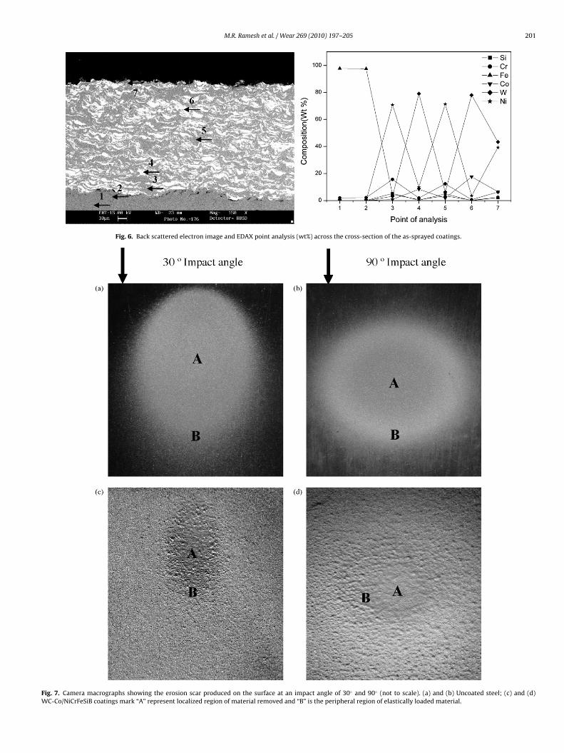
The photographs showing the erosion scar produced on theeroded surface at different impact angles of 30◦ and 90◦ are shownin Fig. 7. The centre portion of the eroded scar represents localizedregion of material removal which is surrounded by region of elas-tically loaded material. The erosion rate curves along with the barchart indicating the volumetric steady state wear loss are shown inFigs. 8 and 9. The steady state volume erosion rate of the uncoatedGrA1 steel at 30◦ impingement is higher than that at 90◦ which isa characteristic behavior of the ductile materials, where materialremoval takes place predominantly by plastic deformation. In gen-eral, the incremental erosion rate curves follow the same forms asthat for the ductile steels at 90◦, having a low initial rate, reaching apeak after 50 g of impacting particles and, subsequently, reaching asteady state erosion rate which is considerably lower than the peakrate [25–27]. WC-Co/NiCrFeSiB coatings exemplify brittle behavioras a function of impact angle, where it exhibit higher wear rate at90◦ impact angle. However the difference in magnitude of steadystate erosion rates at 30◦ and 90◦ impact angles is marginal and liesin a narrow range and hence it may not be conclusive in predict-ing the ductile or brittle nature of the coating. Hutchings [26] andSundararajan and Roy [4] reported that the angular dependence oferosion is not a characteristic of the material alone, but dependsalso on the conditions of erosion and hence suggest that the termsbrittle and ductile in the context of erosion should therefore beused with caution. This leads to the further detailed microscopicanalysis.
The uncoated GrA1 steels exhibit lower erosive loss when
ditions. This may be due to the embedment of silica particles intothe surface, which might bestow some shielding effect against fur-ther material loss. It is well established that the ratio of hardnessof the erodent particles (Hp) to the target hardness (Ht), has a con-
ng elemental composition (wt%) and spectra at selected points.
M.R. Ramesh et al. / Wear 269 (2010) 197–205 201
Fig. 6. Back scattered electron image and EDAX point analysis (wt%) across the cross-section of the as-sprayed coatings.
Fig. 7. Camera macrographs showing the erosion scar produced on the surface at an impact angle of 30◦ and 90◦ (not to scale). (a) and (b) Uncoated steel; (c) and (d)WC-Co/NiCrFeSiB coatings mark “A” represent localized region of material removed and “B” is the peripheral region of elastically loaded material.
202 M.R. Ramesh et al. / Wear 269 (2010) 197–205
Fe
tpoicpc
Fm
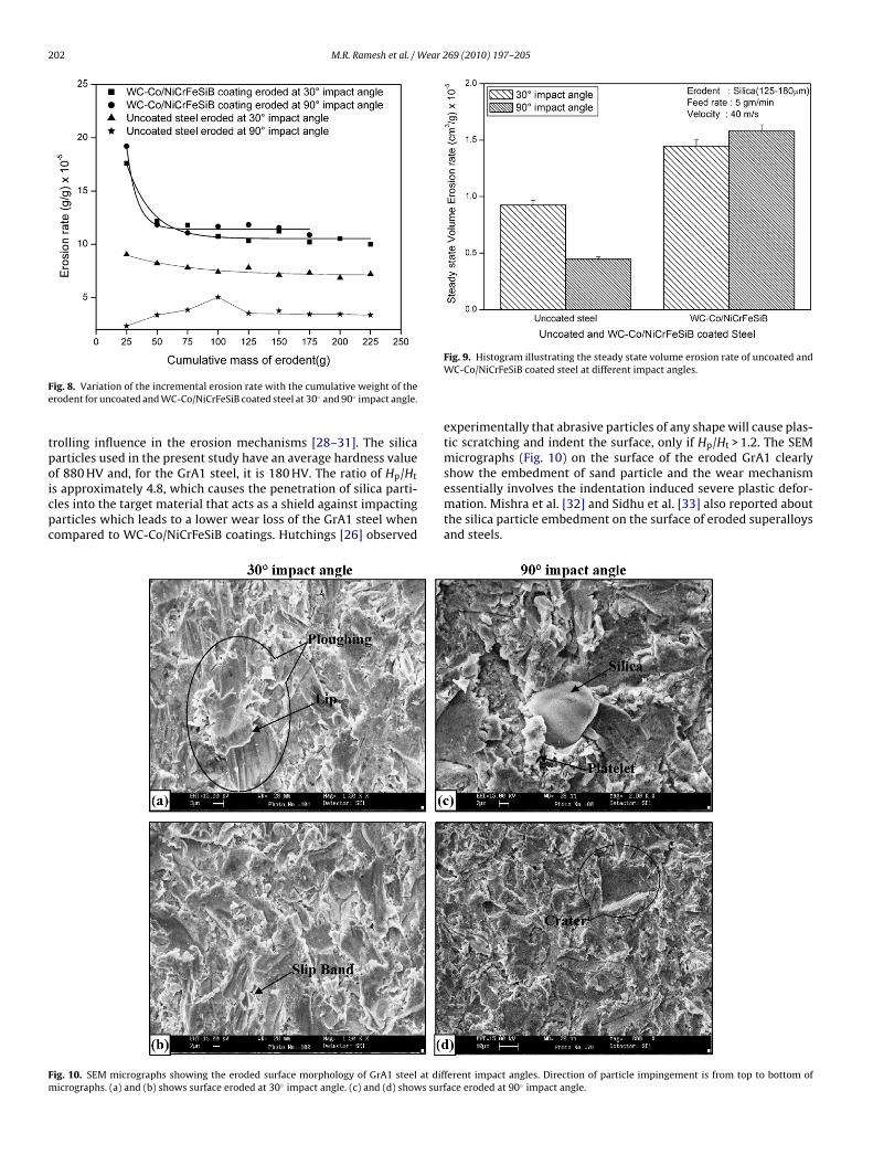
ig. 8. Variation of the incremental erosion rate with the cumulative weight of therodent for uncoated and WC-Co/NiCrFeSiB coated steel at 30◦ and 90◦ impact angle.
rolling influence in the erosion mechanisms [28–31]. The silicaarticles used in the present study have an average hardness valuef 880 HV and, for the GrA1 steel, it is 180 HV. The ratio of Hp/Ht
s approximately 4.8, which causes the penetration of silica parti-les into the target material that acts as a shield against impactingarticles which leads to a lower wear loss of the GrA1 steel whenompared to WC-Co/NiCrFeSiB coatings. Hutchings [26] observed
ig. 10. SEM micrographs showing the eroded surface morphology of GrA1 steel at dificrographs. (a) and (b) shows surface eroded at 30◦ impact angle. (c) and (d) shows surf
Fig. 9. Histogram illustrating the steady state volume erosion rate of uncoated andWC-Co/NiCrFeSiB coated steel at different impact angles.
experimentally that abrasive particles of any shape will cause plas-tic scratching and indent the surface, only if Hp/Ht > 1.2. The SEMmicrographs (Fig. 10) on the surface of the eroded GrA1 clearlyshow the embedment of sand particle and the wear mechanismessentially involves the indentation induced severe plastic defor-
mation. Mishra et al. [32] and Sidhu et al. [33] also reported aboutthe silica particle embedment on the surface of eroded superalloysand steels.ferent impact angles. Direction of particle impingement is from top to bottom oface eroded at 90◦ impact angle.

M.R. Ramesh et al. / Wear 269 (2010) 197–205 203
F al ana
3
awmi
ig. 11. SEM micrographs showing the surface morphology and EDAX composition
.5. Erosion mechanism
The WC-Co/NiCrFeSiB coating eroded at 30◦ impact angle showssurface morphology (Fig. 11) with number of grooves and lipshich indicated the material removal by ploughing and cuttingechanism. Material loss is in the form of platelets by repeated
mpact of erodent. It is apparent from the micrograph that groove
lysis at some points on WC-Co/NiCrFeSiB coated steels eroded at 30◦ impact angle.
might have formed predominantly in the softer binder region, leadsto dislocation of hard WC particles. The grooves in the binder
region act as failure initiating concentrators and small carbidegrains crumble off uncrushed, whereas the main mechanism oflarge grains failure is by chipping [29]. The magnified micrograph(Fig. 11b) shows an evidence of carbide particle pull out. The EDAXanalysis at point 1, confirms the particle as tungsten carbide and
204 M.R. Ramesh et al. / Wear 269 (2010) 197–205
Fig. 12. SEM micrographs showing the surface morphology of WC-Co/NiCrFeSiB coated steels eroded at 90◦ impact angle. Note crater and lips in (a) and groove formed dueto carbide pull out in (b).
F iCrFe
aoCre
pso
Fa
ig. 13. SEM micrographs across the cross-section of the eroded region of WC-Co/N
nalysis at point 2 represents nickel rich binder matrix. Similarbservations of carbide pull out from the WC-Co, WC-Co-Cr andr3C2-20NiCr coating surface at shallow angle of impact have beeneported by Hawthorne et al. [34], Feng and Ball [35] and Murthy
t al. [25].The coating eroded at 90◦ impact angle showed a surface mor-hology (Fig. 12) with a numerous crater formed by impactingilica erodent. The groove marked in Fig. 12b shows the evidencef carbide particle pull out and gross spalling of the coating. Craters
ig. 14. 3D optical profile from the centre of an eroded WC-Co/NiCrFeSiB coating which snd (b) eroded at 90◦ impact angle.
SiB coatings. (a) Eroded at 30◦ impact angle and (b) eroded at 90◦ impact angle.
formed are surrounded by lips suggesting strain localization whichis common feature in ductile erosion mode. Such ductile extru-sion of material might have predominantly occurred in the softernickel-based metallic binder matrix.
There are indications of subsurface cracks in the cross-sectionalview as shown in Fig. 13. The crater and hillocks observed on thesurface indicated the material removal by eroding silica particles.3D optical profile (Fig. 14) of eroded coating at shallow impactangle shows material removal from the binder matrix. Channel
hows depth profiles (scanned area: 591 × 449 �m). (a) Eroded at 30◦ impact angle

ear 2
lroer
cteddaeb
4
(
(
(
(
R
[
[
[
[
[
[
[
[
[
[
[
[[
[
[
[
[
[
[
[
[
[
[
[
[
M.R. Ramesh et al. / W
ike regions observed, indicate the regions of exaggerated materialemoval from the surface. Wider crater of 11.3 �m deep has beenbserved at normal impact. The surface roughness of the coatingroded at 30◦ and 90◦ impact angle is found to be 2.85 and 3.84 �m,espectively.
Consequently the morphology of the eroded surface indicatesraters, grooves formed in binder matrix characterized by lips atheir rim, platelet formation and carbide particle pull out as thexisting erosion mechanism. These mechanisms signify compositeuctile and brittle modes of erosion, although the brittle mode isominant. Hussainova et al. [29], Feng and Ball [35] and Kulu etl. [36] also observed combination of ductile and brittle mode ofrosion with WC-Co hard metals and coatings and titanium carbidease cermets.
. Conclusions
1) High-velocity oxy-fuel thermal spraying with oxygen and liquidpetroleum gas as the fuel gases has been used successfully todeposit WC-Co/NiCrFeSiB alloy coatings on boiler tube steels.LPG fuel gas is cheap and readily available as compared toother fuels used for HVOF spraying. Under the given sprayparameters, seemingly dense laminar structured coating withan average thickness of 290 �m and average porosity of 0.5% hasbeen achieved. The higher cohesive strength accompanied withlower porosity of the coating deposited resulted in hardnessvalue of 1223 HV.
2) WC-Co/NiCrFeSiB coatings show retention of higher amountof WC in matrix with a minor amount of W2C brittle phase.Decomposition and decarburization of the coating powder arenegligible due to higher particle speed and chosen parametersin HVOF spraying.
3) The erosion resistance of WC-Co/NiCrFeSiB coating may beattributed to composite ductile and brittle modes of materialremoval, although brittle mode is dominant. The morphologyof the eroded surface points out craters, groove formation inbinder matrix, lips and platelet formation, and carbide particlepull out as the existing erosion mechanism.
4) Substrate GrA1 steel exhibits lower steady state volume erosionrate in comparison to HVOF sprayed WC-Co/NiCrFeSIB coat-ings under similar test conditions. The higher hardness ratiobetween silica erodent particle and substrate steel might havecaused the penetration of silica particles into the surface whichbestow some shielding effect against impacting particles andindentation induced severe plastic deformation leads to lowererosion loss.
eferences
[1] C.S. Ramesh, S.K. Seshadri, K.J. Iyer, A survey of aspects of wear of metals, IndianJ. Technol. 29 (1991) 179–185.
[2] J.R. Davis, Surface engineering for corrosion and wear resistance, ASM Int.(2001) 61–62.
[3] G. Sundararajan, The solid particle erosion of metallic materials: the rational-ization of the influence of material variables, Wear 186–187 (1995) 129–144.
[4] T. Sundararajan, M. Roy, Solid particle erosion behavior of metallic materials atroom and elevated temperatures, Tribol. Int. 30 (1997) 339–359.
[5] S.C. Stultz, J.B. Kitto (Eds.), Steam: Its Generation and Use, Babcock and Wilcox,Barberton, OH, 1992.
[
[
69 (2010) 197–205 205
[6] M.A. Uusitalo, P.M.J. Vuoristo, T.A. Mantyla, High temperature corrosion of coat-ings and boiler steels in oxidizing chlorine-containing atmosphere, Mater. Sci.Eng. A: Struct. 346 (2003) 168–177.
[7] P.S. Sidky, M.G. Hocking, Review of inorganic coatings and coating processesfor reducing wear and corrosion, Brit. Corros. J. 34 (1999) 171–183.
[8] M.A. Uusitalo, P.M.J. Vuoristo, T.A. Mantyla, High temperature corrosion of coat-ings and boiler steels in reducing chlorine-containing atmosphere, Surf. Coat.Technol. 161 (2002) 275–285.
[9] P.M. Rogers, I.M. Hutchings, J.A. Little, Coatings and surface treatments for pro-tection against low-velocity erosion–corrosion in fluidized beds, Wear 186/187(1995) 238–246.
10] N.G. Solomon, Erosion-resistant coatings for fluidised bed boilers, Mater. Per-form. 37 (1998) 38–43.
11] K.R. Luer, J.N. DuPont, A.R. Marder, High temperature sulfidation of Fe3Al ther-mal spray coatings at 600 ◦C, Corrosion 56 (2000) 189–198.
12] M. Mohanty, R.W. Smith, M. De Bonte, J.P. Celis, E. Lugscheider, Sliding wearbehavior of thermally sprayed 75/25 Cr3C2/NiCr wear resistant coatings, Wear198 (1996) 251–266.
13] J.M. Miguel, J.M. Guilemany, S. Vizcaino, Tribological study of NiCrBSi coatingobtained by different processes, Tribol. Int. 36 (2003) 181–187.
14] P.L. Hurricks, Some aspects of the metallurgy and wear resistance of surfacecoatings, Wear 22 (1972) 291–320.
15] H. Wang, W. Xia, Y. Jin, A study on abrasive resistance of Ni-based coatings witha WC hard phase, Wear 195 (1996) 47–52.
16] P. Kulu, T. Pihl, Selection criteria for wear resistance powder coatings underextreme erosive wear conditions, J. Therm. Spray Technol. 11 (2002) 517–522.
17] H.-J. Kim, S.-Y. Hwang, C.-H. Lee, P. Juvanon, Assessment of wear performanceof flame sprayed and fused Ni-based coatings, Surf. Coat. Technol. 172 (2003)262–269.
18] A.W. Ruff, L.K. Ives, Measurement of solid particle velocity in erosive wear,Wear 35 (1975) 195–199.
19] J.C. Miranda, A. Ramalho, Abrasion resistance of thermal sprayed compositecoatings with a nickel alloy matrix and a WC hard phase. Effect of depositiontechnique and re-melting, Tribol. Lett. 11 (2001) 37–48.
20] J. Vicenzi, D.L. Villanova, M.D. Lima, A.S. Takimi, C.M. Marques, C.P. Bergmann,HVOF-coatings against high temperature erosion (∼300 ◦C) by coal fly ash inthermoelectric power plant, Mater. Des. 27 (2006) 236–242.
21] J.R. Nicholls, Designing oxidation-resistant coatings, JOM 52 (2000) 28–35.22] B.S. Sidhu, Studies on the role of coatings in improving resistance to hot corro-
sion and degradation, Ph.D. Thesis, Met. & Mat. Engg. Dept., Indian Institute ofTechnology Roorkee, Roorkee, 2003.
23] T. Sundararajan, S. Kuroda, F. Abe, Steam oxidation studies on 50Ni–50Cr HVOFcoatings on 9Cr–1Mo steel: change in structure and morphology across thecoating/substrate interface, Mater. Trans. 45 (2004) 1299–1305.
24] H.V. Hidalgo, F.J.B. Varela, A.C. Menéndez, S.P. Martínez, Influence of thethermal-spray procedure on the properties of a nickel–chromium coating, J.Mater. Sci. 37 (2002) 649–654.
25] J.K.N. Murthy, D.S. Rao, B. Venkataraman, Effect of grinding on the erosionbehavior of a WC–Co–Cr coating deposited by HVOF and detonation gun sprayprocesses, Wear 249 (2001) 592–600.
26] I.M. Hutchings, Tribology: Friction and Wear of Engineering Materials, EdwardArnold Publication, 1992.
27] A. Levy, G. Hickey, Erosion of corrosion-resistant surface treatments on alloysteels, Wear 108 (1986) 61–79.
28] S. Lathabai, M. Ottmüller, I. Fernandez, Solid particle erosion behaviour of ther-mal sprayed ceramic, metallic and polymer coatings, Wear 221 (1998) 93–108.
29] I. Hussainova, J. Kübarsepp, I. Shcheglov, Investigation of impact of solid parti-cles against hard metal and cermet targets, Tribol. Int. 32 (1999) 337–344.
30] P.H. Shipway, L.M. Hutchings, The role of particle properties in the erosion ofbrittle materials, Wear 193 (1996) 105–113.
31] J.A. Hearley, J.A. Little, A.J. Sturgeon, The erosion behaviour of NiAl intermetalliccoatings produced by high velocity oxy-fuel thermal spraying, Wear 233–235(1999) 328–333.
32] S.B. Mishra, S. Prakash, K. Chandra, Studies on erosion behavior of plasmasprayed coatings on a Ni-based superalloy, Wear 260 (2006) 422–432.
33] S.H. Singh, S.B. Singh, S. Prakash, Solid particle erosion of HVOF sprayed NiCrand Stellite-6 coatings, Surf. Coat. Technol. 202 (2007) 232–238.
34] H.M. Hawthorne, B. Arsenault, J.P. Immarigeon, J.G. Legoux, V.R. Parameswaran,
Comparison of slurry and dry erosion behaviour of some HVOF thermal sprayedcoatings, Wear 225–229 (1999) 825–834.35] Z. Feng, A. Ball, The erosion of four materials using seven erodents—towards anunderstanding, Wear 233–235 (1999) 674–684.
36] P. Kulu, I. Hussainova, R. Veinthal, Solid particle erosion of thermal sprayedcoatings, Wear 258 (2005) 488–496.