Wear resistance and wear mechanisms of WC–12%Co thermal sprayed coatings in three-body abrasion
13
Ž . Wear 233–235 1999 575–587 www.elsevier.comrlocaterwear Wear resistance and wear mechanisms of WC–12%Co thermal sprayed coatings in three-body abrasion Antonio Cesar Bozzi, Jose Daniel Biasoli de Mello ) ˆ ´ ´ Laboratorio de Tribologia e Materiais, Departamento de Ciencias Fısicas, UniÕersidade Federal de Uberlandia, Uberlandia, M.G., Brazil ´ ˆ ´ ˆ ˆ Abstract In this study, the three-body abrasion resistance of AISI 1020 annealed steel samples coated with WC–12%Co coatings produced by the Jet Kote w thermal spray process was evaluated. The tests were performed using SiO , Al O and SiC as abrasives and five levels of 2 2 3 stress ranging from 0.10 to 0.60 MPa. By measuring the weight loss, the wear rate was evaluated after reaching the steady state of wear. Characterisation of the abrasives was performed using an image analyser and scanning electron microscopy. The microstructure and wear mechanisms of the coatings were characterised by scanning electron microscopy. The relationship between stress and wear rate was found to be dependant on abrasive type; this is due to different degrees of fragmentation of the abrasive. The effect of stress on the wear rate depended on the nature of the abrasive due to the fragmentation process of the abrasives. The results indicated that abrasion resistance and predominant wear mechanisms were strongly dependent on abrasive hardness. In tests using SiO abrasive a combination of 2 micropolishing associated with gradual degradation of the lamellae was the predominant wear mechanism. Plastic deformation by microploughing and microcutting were the predominant wear mechanism in tests with Al O abrasive. In tests with SiC abrasive, 2 3 interlamellar brittle fracture was the predominant mechanism. q 1999 Elsevier Science S.A. All rights reserved. Keywords: WC–12%Co; Three-body abrasion; Abrasive wear; AISI 1020 1. Introduction Wear is defined as the progressive removal of material from surface due to mechanical movement andror chemi- cal processes. Among the various wear mechanisms, abra- sive wear — detachment of material from surfaces in relative motion, caused by protrusions andror hard parti- cles between the opposing surfaces or fixed in one of them — is the most important one due to its destructive charac- Ž ter and its high occurrence frequency 50% of total wear . wx failure 1. Its control and minimisation depends essentially on the appropriate selection of materials. With this objective, one usually uses polyphasic materials formed by one hard phase with characteristics close to those of ceramic materi- wx als, cemented by a ductile matrix 2 . An increasingly popular alternative to the use of wear resistant bulk materials is surface engineering to produce materials that are wear resistant, with the objective of wx maximising the benefitrcost relationship 3 . The surface ) Corresponding author. Tel.: q44-1223-334503; fax: q44-1223- 334567; E-mail: [email protected] engineer aims to produce composite materials where the substrate and the coating or surface modification provide superior performance to that which would be obtained by each of the parts individually. The performance obtained is always a combination of various physical, chemical, me- chanical, metallurgical and thermal properties of the sub- strate and coating. In this context, the use of high velocity Ž . oxy-fuel HVOF thermal sprayed WC–Co deposits looks promising for wear protection due to the excellent combi- w x nation of mechanical properties of this cermet 3,4 . HVOF spraying is one of many processes used for spraying coatings with tribological properties. In this pro- cess the combustion reactions between oxygen and a fuel, like propylene, projects particles at high temperature and high velocity towards the substrate. The coatings produced have low porosity, high adhe- sion to the substrate and low oxide content due to the high w x velocities used 5,6 . Recently various versions of the high velocity combus- tion thermal spray process have been marketed, such as Jet Kote w . In this process, the continual internal combustion of a gas mixture of high pressure oxygen with fuel such as hydrogen, propane and propylene produces gases that are 0043-1648r99r$ - see front matter q 1999 Elsevier Science S.A. All rights reserved. Ž . PII: S0043-1648 99 00206-9
Transcript of Wear resistance and wear mechanisms of WC–12%Co thermal sprayed coatings in three-body abrasion
Ž .Wear 233–235 1999 575–587www.elsevier.comrlocaterwear
Wear resistance and wear mechanisms of WC–12%Co thermal sprayedcoatings in three-body abrasion
Antonio Cesar Bozzi, Jose Daniel Biasoli de Mello )ˆ ´ ´Laboratorio de Tribologia e Materiais, Departamento de Ciencias Fısicas, UniÕersidade Federal de Uberlandia, Uberlandia, M.G., Brazil´ ˆ ´ ˆ ˆ
Abstract
In this study, the three-body abrasion resistance of AISI 1020 annealed steel samples coated with WC–12%Co coatings produced bythe Jet Kotew thermal spray process was evaluated. The tests were performed using SiO , Al O and SiC as abrasives and five levels of2 2 3
stress ranging from 0.10 to 0.60 MPa. By measuring the weight loss, the wear rate was evaluated after reaching the steady state of wear.Characterisation of the abrasives was performed using an image analyser and scanning electron microscopy. The microstructure and wearmechanisms of the coatings were characterised by scanning electron microscopy. The relationship between stress and wear rate was foundto be dependant on abrasive type; this is due to different degrees of fragmentation of the abrasive. The effect of stress on the wear ratedepended on the nature of the abrasive due to the fragmentation process of the abrasives. The results indicated that abrasion resistance andpredominant wear mechanisms were strongly dependent on abrasive hardness. In tests using SiO abrasive a combination of2
micropolishing associated with gradual degradation of the lamellae was the predominant wear mechanism. Plastic deformation bymicroploughing and microcutting were the predominant wear mechanism in tests with Al O abrasive. In tests with SiC abrasive,2 3
interlamellar brittle fracture was the predominant mechanism. q 1999 Elsevier Science S.A. All rights reserved.
Keywords: WC–12%Co; Three-body abrasion; Abrasive wear; AISI 1020
1. Introduction
Wear is defined as the progressive removal of materialfrom surface due to mechanical movement andror chemi-cal processes. Among the various wear mechanisms, abra-sive wear — detachment of material from surfaces inrelative motion, caused by protrusions andror hard parti-cles between the opposing surfaces or fixed in one of them— is the most important one due to its destructive charac-
Žter and its high occurrence frequency 50% of total wear. w xfailure 1 .
Its control and minimisation depends essentially on theappropriate selection of materials. With this objective, oneusually uses polyphasic materials formed by one hardphase with characteristics close to those of ceramic materi-
w xals, cemented by a ductile matrix 2 .An increasingly popular alternative to the use of wear
resistant bulk materials is surface engineering to producematerials that are wear resistant, with the objective of
w xmaximising the benefitrcost relationship 3 . The surface
) Corresponding author. Tel.: q44-1223-334503; fax: q44-1223-334567; E-mail: [email protected]
engineer aims to produce composite materials where thesubstrate and the coating or surface modification providesuperior performance to that which would be obtained byeach of the parts individually. The performance obtained isalways a combination of various physical, chemical, me-chanical, metallurgical and thermal properties of the sub-strate and coating. In this context, the use of high velocity
Ž .oxy-fuel HVOF thermal sprayed WC–Co deposits lookspromising for wear protection due to the excellent combi-
w xnation of mechanical properties of this cermet 3,4 .HVOF spraying is one of many processes used for
spraying coatings with tribological properties. In this pro-cess the combustion reactions between oxygen and a fuel,like propylene, projects particles at high temperature andhigh velocity towards the substrate.
The coatings produced have low porosity, high adhe-sion to the substrate and low oxide content due to the high
w xvelocities used 5,6 .Recently various versions of the high velocity combus-
tion thermal spray process have been marketed, such as JetKotew. In this process, the continual internal combustionof a gas mixture of high pressure oxygen with fuel such ashydrogen, propane and propylene produces gases that are
0043-1648r99r$ - see front matter q 1999 Elsevier Science S.A. All rights reserved.Ž .PII: S0043-1648 99 00206-9

( )A.C. Bozzi, J.D.B. de MellorWear 233–235 1999 575–587576
accelerated as they are forced through a reduced section.This promotes a significant velocity increase, allowing the
w xgas to reach hypersonic velocities 5,7,8 . The initial gasvelocity and temperature are reported to be close to 1300
w xmrs and 30008C respectively 5 .The coating is formed by particles of liquid andror
mushy materials that strike against the substrate wherethey form thin platelets called lamellae or ‘‘splats’’, whichcover the surface irregularities. The lamellae cool rapidly,with rates that can reach 106 K sy1 depending on the
w xthermal spray process used, and solidify 6 .The solidification front moves progressively through the
lamellae and away from the substrate, which acts as theheat sink. The extent of particle flattening during sprayingdepends on factors such as degree of particle melting,liquid viscosity and wettability. Other particles that areprojected over the already deposited material acquire thesame lamellar shape, forming anisotropic structures paral-lel to the interface. The result of such a depositing process,which is repeated millions of times, is a coating with a
w xstructure of splats, voids and oxides 6 .The properties and performance of WC–Co coatings are
attributed to a complex function of: size, shape and distri-bution of carbides, hardness and toughness of matrix,carbon and cobalt matrix content, among others. Previousinvestigations of the causal relationship between deposi-tion process parameters, microstructure and wear perfor-mance have shown that to reach the best output the coatingshould have high WC content finely dispersed and no ´
phase, or Co W C type carbide like for example Co W Cx y z 6 6w xand Co W C 8–10 .3 3
This depends essentially on minimising oxidation anddissolution of WC during spraying, which is a function ofthe powder characteristics, flame temperature and particlevelocity.
The carbon from carbides can form oxy-carbides and itcan diffuse into the matrix or react with cobalt and tung-sten promoting the formation of amorphous phases that arehard and brittle. This change to the matrix has a significanteffect on the coating performance. Although this decarbur-
w xization can be reduced, it cannot be eliminated 8,9 .These reactions have a negative effect on coating prop-
erties, mainly for wear applications and they increase asthe flame temperature and particle dwell time increase. Incomparison with the plasma spray process, the HVOFprocess allows lower particle dwell time and lower flametemperature, which results in lower WC degradation dur-
Ž .ing coating and consequently lower W C, W C,O , W and2 2
´ phase content as well as lower matrix carbon contentw x8,10 .
To minimise porosity and obtain good adhesion, theWC–Co feed stock should completely cover the substratebeing coated. This situation is promoted by totally meltingthe particles during spraying. Unfortunately, the sprayparameters that produce good particle melting also pro-
w xmote WC decarburization 10 .
The processing, properties and applications of thesecoatings have been extensively studied. However, there islittle information in the literature about their wear be-haviour, especially in relation to abrasive processes. Fur-thermore, most published works do not analyse their be-haviour in different tribo-environments. Therefore, thisinvestigation focuses on three-body abrasion of WC–CoHVOF coatings with three abrasive medias to better under-stand their tribological behaviour, especially the wearmechanisms in operation.
2. Experimental procedure
2.5 mm thick AISI 1020 steel panels were sand blastedwith coarse alumina and coated by the Jet Kotew process.The deposition parameters are shown in Table 1.
Cylindrical samples were machined by ultrasonic abra-w xsion in coupons, approximately 5.4 mm in diameter 11 .
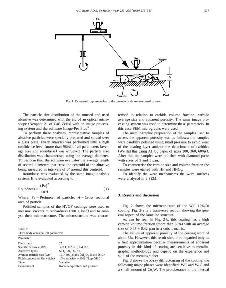
The wear test was performed in a non-standardisedw xthree-body abrasometer 12 . The abrasometer is shown
schematically in Fig. 1, where Dfd.In this configuration three samples were placed inside
small 6 mm diameter holes in a plate, 90 mm from itscentre and 1208 apart. The plate with the sample’s group ispressed by dead weight against a carbon steel disc andplaced inside a cylinder that rotates freely according to itsfriction against the disc. The testing parameters are shownin Table 2.
Lapping oil was used as the medium of abrasive trans-port. The samples were tested in the as-sprayed condition.Before each test, the samples were ultrasonically cleaned,for 5 min in trycloro-ethylene, for another 5 min intryclo-ethylene and finally for 5 min in acetone. All sam-ples were then dried for 30 s.
To evaluate the wear rate, defined as the mass loss perunit of time per unit of cross-sectional area, the test wasinterrupted. The samples were weighed with precision of10y5 g. The wear rate was determined when the ‘‘perma-nent wear regime’’ was reached. For this, the wear ratewas measured as a function of time to a point where it didnot vary significantly. The wear rate was calculated as anaverage of at least 18 results for each condition.
Table 1Jet Kotew process parameters
Parameter
Ž .Powder type JK 112, Stellite WC–Co, 12%CoŽ .Powder size a 325
Fuel PropyleneŽ .O pressure KPa 5172
Ž .Propylene pressure KPa 414Ž .Powder feed rate grs 0.67
Ž .Spray distance m 0.12
( )A.C. Bozzi, J.D.B. de MellorWear 233–235 1999 575–587 577
Fig. 1. Esquematic representation of the three-body abrasometer used in tests.
The particle size distribution of the unused and usedabrasive was determined with the aid of an optical micro-
Ž .scope Neophot 21 of Carl Zeiss with an image process-ing system and the software Image-Pro Plusw.
To perform these analyses, representative samples ofabrasive particles were specially prepared and spread overa glass plate. Every analysis was performed until a high
Ž . Žconfidence level more than 98% of all parameters aver-.age size and roundness was achieved. The particle size
distribution was characterised using the average diameter.To perform this, the software evaluates the average lengthof several diameters that cross the centroid of the abrasivebeing measured in intervals of 58 around this centroid.
Roundness was evaluated by the same image analysissystem. It is evaluated according to:
2PaŽ .Roundnesss 1Ž .
4p A
Where: PasPerimeter of particle; AsCross sectionalarea of particle.
Polished samples of the HVOF coatings were used toŽ .measure Vickers microhardness 300 g load and to anal-
yse their microstructure. The microstructure was charac-
Table 2Three-body abrasion test parameters
Parameter
Ž .Disc rpm 25Ž .Specific Stresses MPa f0.1; 0.2; 0.3; 0.4; 0.6
Abrasives types SiO , Al O , SiC2 2 3Ž . Ž . Ž . Ž .Average particle size mm 191 SiO ; 260 Al O ; 248 SiC2 2 3
Ž .Fluid composition in weight 10% abrasive q90% ‘‘Lap-Oil C’’Time VariableEnvironment Room temperature and pressure
terised in relation to carbide volume fraction, carbideaverage size and apparent porosity. The same image pro-cessing system was used to determine these parameters. Inthis case SEM micrographs were used.
The metallographic preparation of the samples used toaccess the apparent porosity was as follows: the sampleswere carefully polished using small pressure to avoid wearof the coating layer andror the detachment of carbidesŽ .We did this using Al O paper of sizes 180, 360, 600a .2 3
After this the samples were polished with diamond pastewith sizes of 3 and 1 mm.
To characterise the carbide size and volume fraction thesamples were etched with HF and HNO .3
To identify the wear mechanisms the worn surfaceswere analysed in a SEM.
3. Results and discussion
Fig. 2 shows the microstructure of the WC–12%Cocoating. Fig. 2-a is a transverse section showing the gen-eral aspect of the lamellae structure.
As can be seen in Fig. 2-b, this coating has a highŽ .carbide volume fraction more than 85% with an average
size of 0.95"0.42 mm in a cobalt matrix.The values of apparent porosity of the coating were of
about 3%. However, this result should be regarded only asa first approximation because measurements of apparentporosity in this kind of coating are sensitive to metallo-graphic methodology and depend on the experience andskill of the metalographer.
Fig. 3 shows the X-ray diffractogram of the coating; thefollowing major phases were identified: WC and W C and2
a small amount of Co W. The protuberance in the interval3

( )A.C. Bozzi, J.D.B. de MellorWear 233–235 1999 575–587578
Fig. 2. Microstructure of WC–12%Co coating. a — Transverse section. b — after etching with HFrHNO . SEM, Secondary electron image.3
between 308 and 508 in 2u is attributed to the amor-Ž .phousrnanocrystaline nature of the binder phase Co .
This amorphization is often found in these coatings due tow xits high velocity of solidification 13 .
The coatings hardness was 1190"221 HV and that30
of the substrate was 125"11 HV .30
The test time to which the samples were depended onwear rate in each tribological condition. To reach thestable regime in less severe conditions many hours oftesting were necessary while in more severe conditions thestable regime was reached in a minute or less. In everycase, at the end of each test at least 100 mm of coating wasleft.
Fig. 4 shows typical evolution of the wear rate as afunction of abrasion time, where significant variation inmass loss can be noticed. This is a characteristic of theinitial break-in regime and it depends essentially on theplanarity, roughness and uniformity of the sample surface
Fig. 3. X-ray diffractogram of the coating.
to be tested. However, after break-in, the variation ob-served in the next regime, called here the ‘‘permanent’’regime, is still very high, significantly higher than that
w xobserved for three-body abrasion of other materials 2,14 .
Fig. 4. Evolution of the wear rate with testing time, showing the initialand ‘‘permanent’’ regime. a — Abrasive: SiO , stresss0.19 MPa. b —2
Abrasive: SiC, stresss0.40 MPa.
( )A.C. Bozzi, J.D.B. de MellorWear 233–235 1999 575–587 579
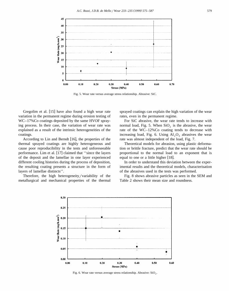
Fig. 5. Wear rate versus average stress relationship. Abrasive: SiC.
w xGregolim et al. 15 have also found a high wear ratevariation in the permanent regime during erosion testing ofWC–17%Co coatings deposited by the same HVOF spray-ing process. In their case, the variation of wear rate wasexplained as a result of the intrinsic heterogeneities of thecoatings.
w xAccording to Lin and Berndt 16 , the properties of thethermal sprayed coatings are highly heterogeneous andcause poor reproducibility in the tests and unforeseeable
w xperformance. Lim et al. 17 claimed that ‘‘since the layersof the deposit and the lamellae in one layer experienceddifferent cooling histories during the process of deposition,the resulting coating presents a structure in the form oflayers of lamellae distincts’’.
Therefore, the high heterogeneityrvariability of themetallurgical and mechanical properties of the thermal
sprayed coatings can explain the high variation of the wearrates, even in the permanent regime.
For SiC abrasive, the wear rate tends to increase withnormal load, Fig. 5. When SiO is the abrasive, the wear2
rate of the WC–12%Co coating tends to decrease withincreasing load, Fig. 6. Using Al O abrasives the wear2 3
rate was almost independent of the load, Fig. 7.Theoretical models for abrasion, using plastic deforma-
tion or brittle fracture, predict that the wear rate should beproportional to the normal load to an exponent that is
w xequal to one or a little higher 18 .In order to understand this deviation between the exper-
imental results and the theoretical models, characterisationof the abrasives used in the tests was performed.
Fig. 8 shows abrasive particles as seen in the SEM andTable 2 shows their mean size and roundness.
Fig. 6. Wear rate versus average stress relationship. Abrasive: SiO .2

( )A.C. Bozzi, J.D.B. de MellorWear 233–235 1999 575–587580
Fig. 7. Wear rate versus average stress relationship. Abrasive: Al O .2 3
Fig. 8. Abrasive grains before and after abrasion testing with stresss0.59 MPa.

( )A.C. Bozzi, J.D.B. de MellorWear 233–235 1999 575–587 581
In the initial state the alumina and silicon carbideparticles have similar average particle sizes, while thequartz particles are smaller. Nevertheless, their mean size,before and after the wear tests, are higher than that re-ported as the critical size for the occurrence of the ‘‘size
w xeffect’’ in abrasive wear 18,22 . It is reasonable to sup-pose that, in this case, the effect of the size of the abrasiveparticles on the wear rate is very low.
ŽAfter abrasion testing at the highest stress f0.59.MPa , the quartz particles fragmented 38%, the alumina
particles 16% and the silicon carbide about 4%.The roundness of the particles was close to unity for all
the abrasives used and they did not significantly changeduring testing.
From the literature, the fracture toughness, K , ofIC
SiO , Al O and SiC is 1.0, 4.9 and 4.6 MPa m1r2,2 2 3w xrespectively 19 . Since the K values give an indicationIC
of the tendency of a material to crack under a givencondition, one expects the quartz to fragment more readilythan Al O and SiC during the tests.2 3
The duration of the tests to which the abrasives weresubjected also had an effect on particle fragmentationsince, in the higher stress conditions, SiO was used over a2
five hour time period while Al O and SiC were used for2 3
only 30 and 5 min, respectively.Therefore, this duration of the tests can explain the
higher fragmentation of the Al O in relation to SiC,2 3
despite their almost identical values of K .IC
In addition, other parameters may also be involvedsince cracking of the abrasives depends on the tribologicalparameters of the counterface.
w xAccording to Eyre 1 particle fragmentation and theaccumulation of debris between abrasive particles areamong the causes of a non-linear wear rate versus loadbehaviour in abrasive wear.
The deviation on the wear rate versus load behaviourcan be explained by the process of fragmentation of theabrasive particles. This fragmentation results in a decreaseof the effective load carrying capability on the abrasive.The decrease in particle size increases the number ofparticles per unit area of the wearing surface, and at aconstant load, the stress on the individual particle de-creases, resulting in shallower scratches, with fewer inden-tations and cracks. In the present case, there is strongevidence for the fragmentation effect, which was signifi-cant for SiO and Al O . In these cases the wear rate2 2 3
decreased and did not vary with load. For the SiC abrasivethe load effect occurred as expected, i.e., the wear rateincreased with load.
w xAccording to Avery 20 , wear rate is very sensitive toabrasive characteristics like chemical composition, struc-ture, shape, size and angularity. Even though the shapeeffect is very important, it is not properly understood. Theparticle shape can have significant influence on the wearmechanisms and will determine if the particles will be ableto roll or to slide during three-body abrasion. Particles withan angular shape can generate wear rates ten times higher
w xthan the rounded ones 18,20 . However, it is difficult todefine and measure angularity, and as a result, roundnessof the abrasive particle is used here instead.
Despite the fact that the roundness–wear rate correla-w xtion has been successfully performed in another work 18 ,
the latter only gives a measure of how much the shapedeviates from a sphere, and therefore there is still need todevelop a more sensitive measurement of particle angular-
w xity 21 . In this work, differences in the roundness of theabrasive particles before and after testing were minor, andthe shape effect was assumed to be negligible.
ŽFig. 9 combines Figs. 5–7, and shows the wear rates in.logarithmic scale for the different abrasives used. On
Fig. 9. Wear rate as a function of abrasive.

( )A.C. Bozzi, J.D.B. de MellorWear 233–235 1999 575–587582
Table 3a. Mean size and roundness of unworn abrasives and after test with stressf0.59 MPa
Ž . Ž .Abrasive Parameter Before test After test Variation % Test time min
Ž .SiO Average diameter mm 191"58 118"40 38.20 3302
Roundness 1.04"0.15 1.01"0.07 2.88 –Ž .Al O Average diameter mm 260"47 217"55 16.40 262 3
Roundness 1.05"0.25 1.03"0.15 1.90 –Ž .SiC Average diameter mm 248"42 236"44 4.52 5
Roundness 1.08"0.23 1.04"0.18 3.70 –
b. Abrasive hardness and relative hardness
Ž . Ž .Abrasive Hardness HV Relative hardness H rH30 A M
SiO f1000 0.842
Al O 1800 1.512 3
SiC 2600 2.80
changing from SiO to Al O there was an order of2 2 3
magnitude increase in the wear rate. A similar changeoccurred on moving from Al O to SiC. This is due to the2 3
relative hardness of the coating with respect to the abrasivehardness.
The relative hardness of the abrasive to that of theŽ .material H rH has considerable influence on the mea-A M
w xsured wear rate 18,22 . Table 3 shows the abrasiveshardness and the H rH ratio.A M
Experimental results concerning the abrasive wear ofheterogeneous materials show that, abrasion under condi-tions where H rH -0.9 is ‘‘mild’’ while under condi-A M
tions where H rH )1.5 the abrasion is consideredA M
‘‘severe’’. In between these two values there is a transition
w xfrom ‘‘mild’’ to ‘‘severe’’ 22 . This explains the bigincrease in the wear rate when the abrasive is changedfrom SiO to Al O , the wear conditions change from2 2 3
‘‘mild’’ to ‘‘severe’’. However, the H rH change fromA M
SiC to Al O , according the mildrsevere rational, does2 3
not explain the results in Fig. 9, where one would expect alinear increase in the wear rate with increasing abrasivehardness. This is because this reasoning is valid only whenthe wear is dominated by plastic deformation mechanisms,and in changing from Al O to SiC, the material removal2 3
mechanism probably changes.w xBarbezat et al. 4 have also found a strong dependence
on the nature of the abrasive on the wear rates of WC–12%Co coatings deposited by HVOF process. In their
Fig. 10. Detail of the worn surface of the coating after tests with SiO . a — Stresss0.10 MPa. b — Stresss0.57 MPa.2

( )A.C. Bozzi, J.D.B. de MellorWear 233–235 1999 575–587 583
Ž .two-body abrasion pin-on-disc tests, wear rates changedby more than one order of magnitude in changing theabrasive from SiO to Al O and from Al O to SiC.2 2 3 2 3
This order of magnitude difference in the wear rates asfunction of the abrasive used is a strong indication thatdifferent predominant wear mechanisms are acting in eachcase.
When using SiO abrasives, the relative hardness2
H rH is 0.84, and therefore the abrasive cannot createA M
groovesrscratches or indentations on the surface. In this
case, the most usual wear mechanisms are adhesion orw xcontact fatigue 22 .
w xAccording to Desay et al. 23 , there are some mecha-nisms of abrasive wear that can act in cobalt-based alloysmade by powder metallurgy such as the detachment of thecarbides and formation of large pits followed by themicrocracking of the edges of carbides.
Another mechanism that could be acting in this case isw xbinder extrusion; according to Larsen-Basse 24 , this acts
mainly in the ‘‘mild’’ regime for cemented carbides.
Fig. 11. Detail of sequence of the material removal process in tests with SiO abrasives. a — Stresss0.10 MPa. b — Stresss0.57 MPa. c —2
Stresss0.10 MPa.

( )A.C. Bozzi, J.D.B. de MellorWear 233–235 1999 575–587584
w xThe mechanism proposed by Larsen-Basse 24 can beexplained in this way: the binder is forced to move outsidethe surface of the material by the stress of compression ofthe abrasive particles, due to the fact that the hard phasesŽ .WC, W C deform only slightly. Thus, almost all defor-2
mation occurs in the softer and more ductile matrix. Thehard phase has only a small displacement from the normaland tangential stress applied by the abrasive particles.Multiple and repeated contacts of the abrasive particles arerequired before a significant amount of material can beremoved; this cyclic loading results in an extrusion of thematrix between the hard phase particles. After this re-moval, microcracking andror detachment of hard phaseoccurs when the support and compressive loading of thematrix are no longer present.
Although WC–Co coatings deposited by thermal sprayprocesses have several differences from cemented carbidesŽ .lamellar structure, a greater porosity, etc. , they also havesome very similar characteristics: carbide average sizes areinto the range of micrometers, hard phases in the softmatrix, etc. Thus, it is possible that the wear mechanism ofbinder extrusion also acts on WC–Co thermal sprayed
w xcoatings, as claimed by Bahadur and Yang 25 . In thepresent study, however, no evidence of this mechanism
Ž .was found. The XRD spectrum of the coating Fig. 3 donot show the presence of Cobalt since it wasamorphizedrnanocrystalized. As the matrix has beenamorphizedrnanocrystalized, it is brittle and prevents thebinder extrusion mechanisms from acting.
Fig. 10 shows, in more detail, the worn surfaces aftertests with SiO . It is interesting to observe in these figures2
the absence of groovesrscratches and indentations whichoccur in process governed by plastic deformation. In addi-tion, no evidence of brittle fracture processes could beidentified. In the high stress condition it appears that apolishing process is acting as indicated by the presence of
Ž .various smooth areas, Fig. 10 b . As the stress is reducedŽ .less smooth areas occur, Fig. 10 a . As mentioned previ-
ously increasing the stress results in increased fragmenta-tion of the abrasive which leads to a greater number ofabrasive particles in action and therefore a lower effectiveload acting resulting in a larger polished area.
Near these polished areas rougher areas can be seen,where a process of gradual material removal mechanismsis clearly visible, Fig. 11.
Ž .The removal of individual carbide particles pull outandror small agglomerates of carbides and matrix causesthe detachment of fragments from lamellae. The pull out ofindividual carbide particles andror of agglomerates ofcarbides and matrix result in the formation of fragments
Ž . Ž .from the lamellae, Fig. 11 a and b , which finally detachŽ .themselves, producing the wear, Fig. 11 c .
The process of thermal spraying causes a heterogeneityof structure and topography, with such features as cracks
Ž .and porosity which act as nucleation sites. Fig. 12 .Our suggestion is that, in this tribological situation, the
predominant wear mechanism is a combination of micropolishing and gradual degradation of the lamellae from thepre existent microcracks and porosity, leading to the for-mation of wear debris.
Fig. 13 shows the worn surfaces tested with Al O2 3Ž .abrasives. In Fig. 13 a several grooves and scratches can
Fig. 12. Typical aspect of the surface of the WC–12%Co coating in the as-sprayed condition. a — Aspect General. b — Detail.
( )A.C. Bozzi, J.D.B. de MellorWear 233–235 1999 575–587 585
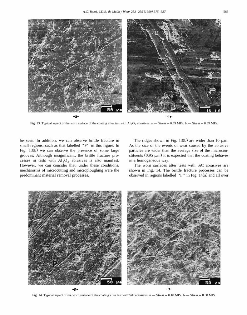
Fig. 13. Typical aspect of the worn surface of the coating after test with Al O abrasives. a — Stresss0.59 MPa. b — Stresss0.59 MPa.2 3
be seen. In addition, we can observe brittle fracture insmall regions, such as that labelled ‘‘F’’ in this figure. In
Ž .Fig. 13 b we can observe the presence of some largegrooves. Although insignificant, the brittle fracture pro-cesses in tests with Al O abrasives is also manifest.2 3
However, we can consider that, under these conditions,mechanisms of microcutting and microploughing were thepredominant material removal processes.
Ž .The ridges shown in Fig. 13 b are wider than 10 mm.As the size of the events of wear caused by the abrasiveparticles are wider than the average size of the microcon-
Ž .stituents 0.95 mm it is expected that the coating behavesin a homogeneous way.
The worn surfaces after tests with SiC abrasives areshown in Fig. 14. The brittle fracture processes can be
Ž .observed in regions labelled ‘‘F’’ in Fig. 14 a and all over
Fig. 14. Typical aspect of the worn surface of the coating after test with SiC abrasives. a — Stresss0.10 MPa. b — Stresss0.58 MPa.
( )A.C. Bozzi, J.D.B. de MellorWear 233–235 1999 575–587586
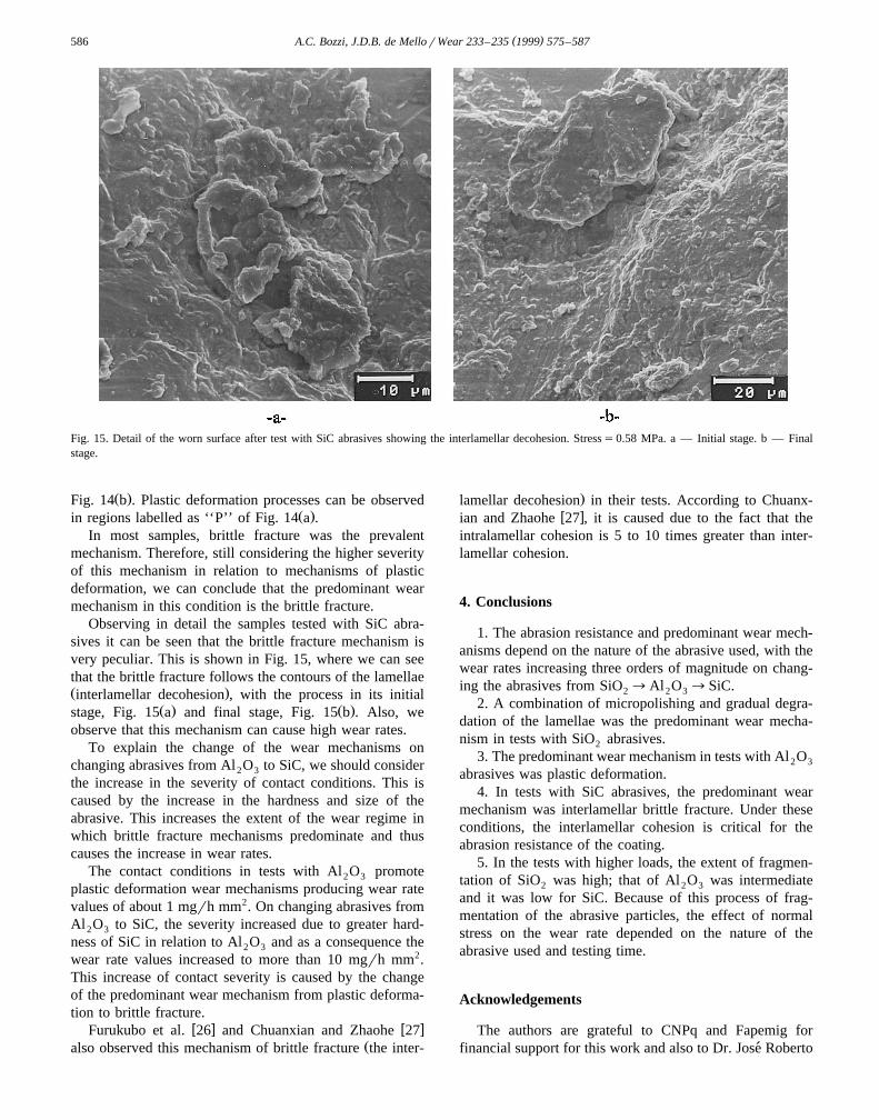
Fig. 15. Detail of the worn surface after test with SiC abrasives showing the interlamellar decohesion. Stresss0.58 MPa. a — Initial stage. b — Finalstage.
Ž .Fig. 14 b . Plastic deformation processes can be observedŽ .in regions labelled as ‘‘P’’ of Fig. 14 a .
In most samples, brittle fracture was the prevalentmechanism. Therefore, still considering the higher severityof this mechanism in relation to mechanisms of plasticdeformation, we can conclude that the predominant wearmechanism in this condition is the brittle fracture.
Observing in detail the samples tested with SiC abra-sives it can be seen that the brittle fracture mechanism isvery peculiar. This is shown in Fig. 15, where we can seethat the brittle fracture follows the contours of the lamellaeŽ .interlamellar decohesion , with the process in its initial
Ž . Ž .stage, Fig. 15 a and final stage, Fig. 15 b . Also, weobserve that this mechanism can cause high wear rates.
To explain the change of the wear mechanisms onchanging abrasives from Al O to SiC, we should consider2 3
the increase in the severity of contact conditions. This iscaused by the increase in the hardness and size of theabrasive. This increases the extent of the wear regime inwhich brittle fracture mechanisms predominate and thuscauses the increase in wear rates.
The contact conditions in tests with Al O promote2 3
plastic deformation wear mechanisms producing wear ratevalues of about 1 mgrh mm2. On changing abrasives fromAl O to SiC, the severity increased due to greater hard-2 3
ness of SiC in relation to Al O and as a consequence the2 3
wear rate values increased to more than 10 mgrh mm2.This increase of contact severity is caused by the changeof the predominant wear mechanism from plastic deforma-tion to brittle fracture.
w x w xFurukubo et al. 26 and Chuanxian and Zhaohe 27Žalso observed this mechanism of brittle fracture the inter-
.lamellar decohesion in their tests. According to Chuanx-w xian and Zhaohe 27 , it is caused due to the fact that the
intralamellar cohesion is 5 to 10 times greater than inter-lamellar cohesion.
4. Conclusions
1. The abrasion resistance and predominant wear mech-anisms depend on the nature of the abrasive used, with thewear rates increasing three orders of magnitude on chang-ing the abrasives from SiO ™Al O ™SiC.2 2 3
2. A combination of micropolishing and gradual degra-dation of the lamellae was the predominant wear mecha-nism in tests with SiO abrasives.2
3. The predominant wear mechanism in tests with Al O2 3
abrasives was plastic deformation.4. In tests with SiC abrasives, the predominant wear
mechanism was interlamellar brittle fracture. Under theseconditions, the interlamellar cohesion is critical for theabrasion resistance of the coating.
5. In the tests with higher loads, the extent of fragmen-tation of SiO was high; that of Al O was intermediate2 2 3
and it was low for SiC. Because of this process of frag-mentation of the abrasive particles, the effect of normalstress on the wear rate depended on the nature of theabrasive used and testing time.
Acknowledgements
The authors are grateful to CNPq and Fapemig forfinancial support for this work and also to Dr. Jose Roberto´

( )A.C. Bozzi, J.D.B. de MellorWear 233–235 1999 575–587 587
Tavares Branco at CETEC, Belo Horizonte, Brazil, forkindly providing the WC–Co coatings. Thanks are alsodue to Rob Trezona, University of Cambridge, UK, for hishelpful comments and correction of the manuscript.
References
w x1 T.S. Eyre, Proc. of the II Seminario Sobre Materiais Resistentes ao´Desgaste, Uberlandia, 1991, 263–292.ˆ
w x2 S.A. Santana, J.D.B. de Mello, Proc. of the III Seminario Brasileiro´de Materiais Resistentes ao Desgaste, Fortaleza, 1994, 147–156.
w x3 A.C. Bozzi, J.R.T.Branco, Proc. of the III Seminario Brasileiro de´Materiais Resistentes ao Desgaste, Fortaleza, 1994, 221–240.
w x Ž .4 G. Barbezat et al., Wear 162-134 1993 529-537.w x5 D.S. Rickerby, A. Matthews, Advanced Surface Coatings: A Hand-
book of Surface Engineering, Blackie & Limited, Glasgow, 1991,368 pp.
w x6 M.M. Lima et al., Proc. of the LI Congresso Anual da ABM, PortoAlegre, 1996, 145–158.
w x7 W.J. Jarosinsky et al., Proc. of the National Thermal Spray Confer-ence, Anaheim, CA, 1993, 153–157.
w x8 T. Kraak et al., Proc. of the International Thermal Spray Conference,Orlando, 1992, 153–158.
w x9 J.E. Nerz et al., Proc. of the Fourth National Thermal Spray Confer-ence, Pittsburgh, 1991, 115–120.
w x10 W.J. Lenling et al., Proc. of the Third National Thermal SprayConference, Long Beach, 1990, 227–232.
´w x11 A.A. Raslan, J.D.B. de Mello, Proc. of the XIII Cbecimat, Aguas deLindoia, 1996, 461–464.´
w x12 S.D. Franco et al., Proc. of the I Seminario de Materiais Resistentes´ao Desgaste, Sao Paulo, 1989, 29–45.˜
w x13 P. Vuoristo et al., Proc. of the National Thermal Spray Conference,Anaheim, 1993, 173–178.
w x Ž .14 H.L. Costa et al., Wear 203–204 1997 626–632.w x15 J.A.R. Gregolim et al., Proc. of the III Seminario Brasileiro de´
Materiais Resistentes ao Desgaste, Fortaleza, 1994, 21–40.w x Ž .16 C.K. Lin, C.C. Berndt, Journal of Thermal Spray Technology 1 3
Ž .1994 75–104.w x Ž .17 L.C. Lim et al., Surface and Coatings Technology 82 1996 151–
161.w x18 I.M. Hutchings, Tribology: Friction and Wear of Engineering Mate-
rials, CRC Press, Boca Raton, 1992, 273 pp.w x19 B. Bhushan, B.K. Gupta, Handbook of Tribology, McGraw-Hill,
1991, 561 pp.w x20 H.S. Avery, Proc. Int. Conf. On Wear of Materials, 1977, 148–157.w x Ž .21 M.A. Verspui et al., Wear 199 1996 122–126.w x22 K.H. Zum Gahr, Microstructure and Wear of Materials, Amsterdam,
Elsevier, New York, 1987, 590 pp.w x23 V.M. Desay et al., Proc. Int. Conf. On Wear of Materials, 1983,
32–37.w x24 J. Larsen-Basse, Binder Extrusion of Sliding Wear of WC–Co
Alloys, Proc. Int. Conf. On Wear of Materials, 1977, pp. 39–44.w x Ž .25 S. Bahadur, C. Yang, Wear 196 1996 156–163.w x26 K. Furukubo et al., Proc. of the International Thermal Spray Confer-
ence, Orlando, 1992, 705–709.w x27 D. Chuanxian, T. Zhaohe, Proc. of the International Thermal Spray
Conference, Orlando, 1992, 673–677.