EROSION CONTROL BEST MANAGEMENT PRACTICES ...
107
ORANGE COUNTY STORMWATER PROGRAM EROSION CONTROL BEST MANAGEMENT PRACTICES (BMP) FIELD EVALUATION January 2007 A cooperative project between the County of Orange, Orange County Flood Control District and the incorporated cities of Orange County
-
Upload
khangminh22 -
Category
Documents
-
view
4 -
download
0
Transcript of EROSION CONTROL BEST MANAGEMENT PRACTICES ...

ORANGE COUNTY STORMWATER PROGRAM
EROSION CONTROL BEST MANAGEMENT PRACTICES (BMP)
FIELD EVALUATION
January 2007
A cooperative project between the County of Orange, Orange County Flood Control District and the incorporated cities of Orange County

EROSION CONTROL BMP FIELD EVALUATION
Orange County Storm Water Program i January 2007 Erosion Control BMP Field Evaluation
Acknowledgements
The assistance provided by the following individuals and firms in the conduct of this study is gratefully acknowledged: • Mr. Scot Scialpi, The Irvine Company: for providing the use of several lots in the Shady
Canyon development for this study, contractor coordination, and technical advice.
• Mr. Bill Martin, The Irvine Company: for additional assistance with contractor
coordination. • Mr. Andy Iturriria, Terra Novo Inc.:
(www.earthguard.com) for providing erosion control products and labor for the initial installation as well as technical advice.
This report, along with the companion study proposal (RBF, 2003), fulfill requirement XII.A.8 of the NPDES municipal stormwater permit for the County of Orange and local jurisdiction Permittees (Order No. R8-2002-0010) issued by the Santa Ana Regional Water Quality Control Board in 2002.

EROSION CONTROL BMP FIELD EVALUATION
Orange County Storm Water Program ii January 2007 Erosion Control BMP Field Evaluation
Table of Contents Acknowledgements ...................................................................................................................................i
1 Introduction .................................................................................................................................. 1
1.1 BACKGROUND................................................................................................................................. 1 1.2 PURPOSE .......................................................................................................................................... 1 1.3 SCOPE OF WORK ............................................................................................................................. 1
2 Field Evaluation Method............................................................................................................ 2
2.1 TEST SITE SELECTION...................................................................................................................... 2 2.2 TEST SITE DESIGN ........................................................................................................................... 5 2.3 SELECTION OF EROSION CONTROLS .............................................................................................. 5
2.3.1 ULTRATACK .......................................................................................................................... 8 2.3.2 EARTHGUARD....................................................................................................................... 8 2.3.3 EARTHGUARD FIBER MATRIX (FM)..................................................................................... 9 2.3.4 LANDSCAPING MULCH ........................................................................................................ 9
2.4 TEST PLOT PREPARATION .............................................................................................................. 9 2.5 MONITORING ................................................................................................................................ 11 2.6 TEST PLOT MAINTENANCE .......................................................................................................... 11
3 Findings ....................................................................................................................................... 13
3.1 STORM EVENT DATA .................................................................................................................... 13 3.2 VISUAL MONITORING RESULTS ................................................................................................... 14
3.2.1 LOT 15 – 2% (FLAT) SLOPE ................................................................................................ 14 3.2.2 LOT 14 – 5% (MILD) SLOPE................................................................................................ 15 3.2.3 SLOPE AREA – ABOUT 50% SLOPE..................................................................................... 17
4 Conclusion................................................................................................................................... 19
4.1 EROSION CONTROL PERFORMANCE............................................................................................ 19 4.2 RECOMMENDATION...................................................................................................................... 20 4.3 NEXT STEPS ................................................................................................................................... 23
5 References ................................................................................................................................... 24

EROSION CONTROL BMP FIELD EVALUATION
Orange County Storm Water Program iii January 2007 Erosion Control BMP Field Evaluation
Appendices Appendix A: Erosion Control Study Approval Letter from the Santa Ana Regional Board Appendix B: Lot 15 (Flat Slope) Time-Series Photo Progressions Appendix C: Lot 14 (Mild Slope) Time-Series Photo Progressions Appendix D: Slope Area Time-Series Photo Progressions Appendix E: Erosion Control Application Guidance
List of Figures Figure 1. Orange County Soils Map. ...................................................................................................... 2 Figure 2. Test Site (Shady Canyon) Vicinity Map................................................................................. 3 Figure 3. Test Site Lot Locations (aerial view). ..................................................................................... 4 Figure 4. Test Site Lot Locations (before site preparation).................................................................. 5 Figure 5. Test Plot Layout. ....................................................................................................................... 7 Figure 6. Sample Test Plot Signage....................................................................................................... 10 Figure 7. Rain Gauge Setup ................................................................................................................... 12 Figure 8. Monthly Rainfall Accumulation........................................................................................... 13
List of Tables Table 1. Summary of Erosion Control Practices Evaluated ................................................................ 8 Table 2. Summary of Test Plot Erosion Control Application Rates ................................................. 10 Table 3. Observed Performance of Erosion Control Measures......................................................... 20 Table 4. Erosion Control Recommendation and Information........................................................... 22

EROSION CONTROL BMP FIELD EVALUATION
Orange County Storm Water Program 1 January 2007 Erosion Control BMP Field Evaluation
1 Introduction 1.1 Background The NPDES municipal stormwater permit for the County of Orange and local jurisdiction Permittees (Order No. R8-2002-0010) issued by the Santa Ana Regional Water Quality Control Board in 2002 required the Permittees to submit a proposal for a study to evaluate the effectiveness of a group of selected BMPs for controlling erosion during new development (construction). In accordance with Section XII.A.8 of the Permit, the Permittees submitted a study proposal in November 2003 (available at www.ocwatersheds.com). After some refinement of the study scope with Regional Board staff, the modified study was approved by the Regional Board Executive Officer in late October 2004 (refer to Appendix A for approval letter). Although the Permit required only that the field study be completed by the end of the current Permit term (2007), the Permittees had already begun preparations to conduct the study during the 2004-2005 rainy season, therefore the field study was conducted from October 2004 through early May 2005. This report documents the results of the field study. 1.2 Purpose The requirement to conduct an erosion control evaluation was included in the NPDES permit due to Regional Board staff concerns that these controls were not being implemented appropriately at construction sites. Specifically, while Regional Board staff found, through their construction site inspections, that there was generally good understanding and implementation of permanent or long-term erosion controls, they were concerned with what staff thought to be a relatively lower level of appropriate implementation of short-term erosion controls (less than one year duration). The purpose of this study was to evaluate the performance of selected erosion control Best Management Practices (BMPs) to identify those that are more suitable for relatively short durations and that are routinely encountered during active construction operations. This report documents the results of the field study and includes guidance developed because of the study.
1.3 Scope of Work
In November 2003, the Permittees submitted a detailed erosion control study proposal, which discussed the study approach and methodology, as well as other previous related research. Key activities conducted during the 2004-2005 field study included:
Selecting and preparing the test site, and installing storm event monitoring equipment; Selecting and applying the erosion controls to be tested at the test site plots; Monitoring the test plots throughout the 2004-2005 wet season; and Preparing this initial report to document the field evaluation results.

EROSION CONTROL BMP FIELD EVALUATION
Orange County Storm Water Program 2 January 2007 Erosion Control BMP Field Evaluation
2 Field Evaluation Method 2.1 Test Site Selection There were two key criteria for selection of the field test site. The first was to identify a site that had a soil type typical to that of a large portion of the County, to ensure that the study results obtained would be applicable to the largest possible area. The second was to find a site with both steep slopes (about 2 horizontal to 1 vertical, or 2:1) and “flat” pad areas (slopes less than 10:1). The County has a wide variety of soil types, with sandy soils prevalent in the lowland areas, especially in the area north of the current channel of the Santa Ana River in Orange County, while clayey soils are more prevalent in the hills and upland areas (refer to Figure 1). The lowland, valley areas are more highly developed; therefore, less construction activity is occurring in these areas. Since the main areas of development are now occurring in the uplands, such as the Ladera Ranch development east of Mission Viejo or the Santiago Hills development east of the City of Orange, a test site with clayey (Type C or D) soils was needed for the field study.
Figure 1. Orange County Soils Map.

EROSION CONTROL BMP FIELD EVALUATION
Orange County Storm Water Program 3 January 2007 Erosion Control BMP Field Evaluation
Grading for new development projects involves creating slopes of various gradients, although steeper slopes of 50% (2 : 1) between building pads and very mild slopes of less than 5% (20:1) for flat pad areas are common. While the primary focus of this field evaluation was to assess erosion control performance on flat/very mildly-sloped pads, the test site also needed steeper slopes to accommodate Regional Board staff’s desire to evaluate erosion control performance on a steeper nearby “reference” slope. To minimize the time and expense required to obtain suitable land and create the required test slope conditions, the test site also needed to be located within an ongoing new development construction project. To provide a test site that met the above criteria, The Irvine Company offered the use of several lots within its Shady Canyon development for this field evaluation. Shady Canyon is a developing upscale residential area nestled in a secluded canyon between Interstate 405 and State Route 73 in the City of Irvine (Figure 2). The Irvine Company finished the construction of streets/utilities infrastructure and grading of slopes and pads in the Shady Canyon development, and provided the use of Lots 14 and 15 on Needlegrass Street for the flat pad test plots, as well as a steep slope near the end lot on Spike Moss Court for the slope test plots (Figures 3 and 4). These lots were considered representative of typical new development construction areas within the County, met the test site selection criteria, and needed only minor grading to prepare them for use in this field evaluation.
Figure 2. Test Site (Shady Canyon) Vicinity Map.
STUDY SITE

EROSION CONTROL BMP FIELD EVALUATION
Orange County Storm Water Program 4 January 2007 Erosion Control BMP Field Evaluation
Figure 3. Test Site Lot Locations (aerial view).
EROSION CONTROL BMP FIELD EVALUATION
Orange County Storm Water Program 5 January 2007 Erosion Control BMP Field Evaluation
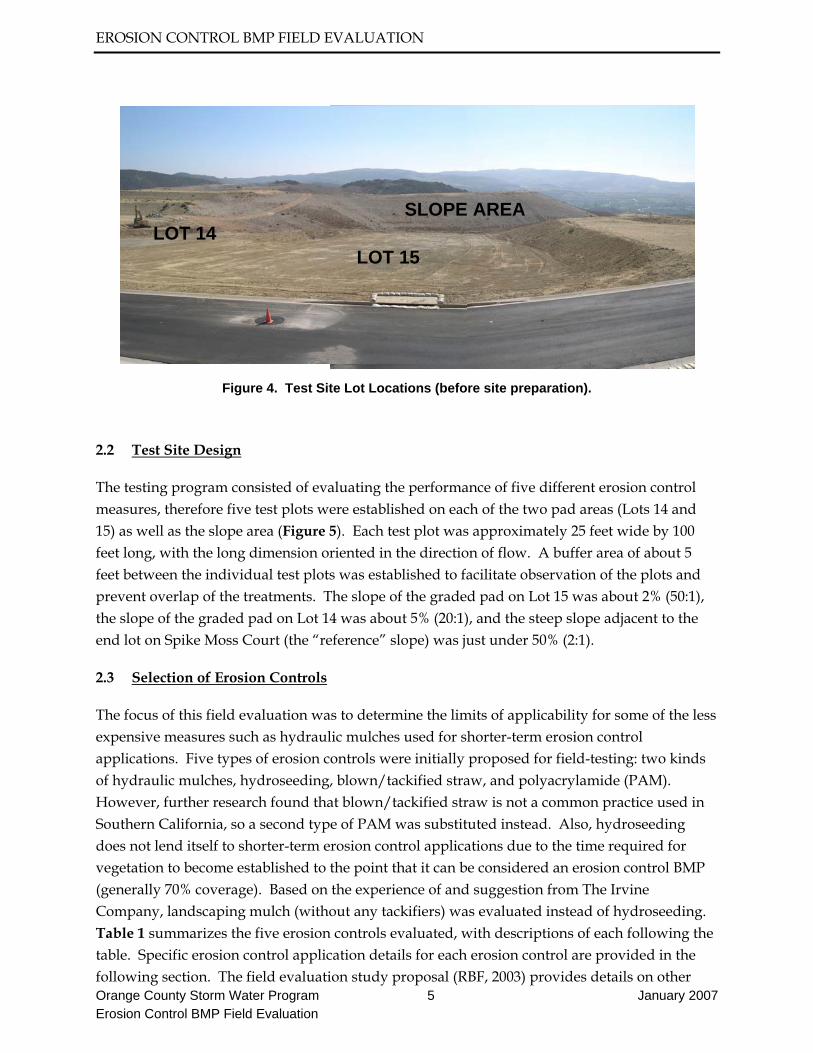
Figure 4. Test Site Lot Locations (before site preparation).
2.2 Test Site Design
The testing program consisted of evaluating the performance of five different erosion control measures, therefore five test plots were established on each of the two pad areas (Lots 14 and 15) as well as the slope area (Figure 5). Each test plot was approximately 25 feet wide by 100 feet long, with the long dimension oriented in the direction of flow. A buffer area of about 5 feet between the individual test plots was established to facilitate observation of the plots and prevent overlap of the treatments. The slope of the graded pad on Lot 15 was about 2% (50:1), the slope of the graded pad on Lot 14 was about 5% (20:1), and the steep slope adjacent to the end lot on Spike Moss Court (the “reference” slope) was just under 50% (2:1).
2.3 Selection of Erosion Controls
The focus of this field evaluation was to determine the limits of applicability for some of the less expensive measures such as hydraulic mulches used for shorter-term erosion control applications. Five types of erosion controls were initially proposed for field-testing: two kinds of hydraulic mulches, hydroseeding, blown/tackified straw, and polyacrylamide (PAM). However, further research found that blown/tackified straw is not a common practice used in Southern California, so a second type of PAM was substituted instead. Also, hydroseeding does not lend itself to shorter-term erosion control applications due to the time required for vegetation to become established to the point that it can be considered an erosion control BMP (generally 70% coverage). Based on the experience of and suggestion from The Irvine Company, landscaping mulch (without any tackifiers) was evaluated instead of hydroseeding. Table 1 summarizes the five erosion controls evaluated, with descriptions of each following the table. Specific erosion control application details for each erosion control are provided in the following section. The field evaluation study proposal (RBF, 2003) provides details on other
LOT 14 LOT 15
SLOPE AREA

EROSION CONTROL BMP FIELD EVALUATION
Orange County Storm Water Program 6 January 2007 Erosion Control BMP Field Evaluation
erosion controls considered but not selected for this evaluation. Except for landscaping mulch, erosion control products listed in Table 1 and labor for the initial installation of these controls were donated by Terra Novo, Inc. of Bakersfield, CA. Disclaimer: The intent of this study was not to evaluate the performance of or to make recommendations on any specific proprietary product. Use of erosion control products listed in Table 1 for this study does not constitute a recommendation or approval for use of any specific proprietary product by the County of Orange and incorporated cities.

EROSION CONTROL BMP FIELD EVALUATION
Orange County Storm Water Program 7 January 2007 Erosion Control BMP Field Evaluation
Figure 5. Test Plot Layout.
EROSION CONTROL BMP FIELD EVALUATION
Orange County Storm Water Program 8 January 2007 Erosion Control BMP Field Evaluation
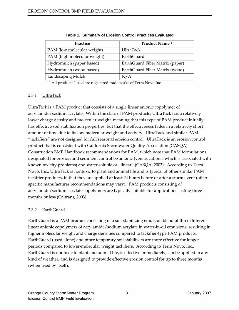
Table 1. Summary of Erosion Control Practices Evaluated
Practice Product Name 1 PAM (low molecular weight) UltraTack PAM (high molecular weight) EarthGuard Hydromulch (paper based) EarthGuard Fiber Matrix (paper) Hydromulch (wood based) EarthGuard Fiber Matrix (wood) Landscaping Mulch N/A
1 All products listed are registered trademarks of Terra Novo Inc. 2.3.1 UltraTack UltraTack is a PAM product that consists of a single linear anionic copolymer of acrylamide/sodium acrylate. Within the class of PAM products, UltraTack has a relatively lower charge density and molecular weight, meaning that this type of PAM product initially has effective soil stabilization properties, but that the effectiveness fades in a relatively short amount of time due to its low molecular weight and activity. UltraTack and similar PAM “tackifiers” are not designed for full seasonal erosion control. UltraTack is an erosion control product that is consistent with California Stormwater Quality Association (CASQA) Construction BMP Handbook recommendations for PAM, which note that PAM formulations designated for erosion and sediment control be anionic (versus cationic which is associated with known toxicity problems) and water soluble or “linear” (CASQA, 2003). According to Terra Novo, Inc., UltraTack is nontoxic to plant and animal life and is typical of other similar PAM tackifier products, in that they are applied at least 24 hours before or after a storm event (other specific manufacturer recommendations may vary). PAM products consisting of acrylamide/sodium acrylate copolymers are typically suitable for applications lasting three months or less (Caltrans, 2003). 2.3.2 EarthGuard EarthGuard is a PAM product consisting of a soil-stabilizing emulsion blend of three different linear anionic copolymers of acrylamide/sodium acrylate in water-in-oil emulsions, resulting in higher molecular weight and charge densities compared to tackifier-type PAM products. EarthGuard (used alone) and other temporary soil stabilizers are more effective for longer periods compared to lower-molecular weight tackifiers. According to Terra Novo, Inc., EarthGuard is nontoxic to plant and animal life, is effective immediately, can be applied in any kind of weather, and is designed to provide effective erosion control for up to three months (when used by itself).

EROSION CONTROL BMP FIELD EVALUATION
Orange County Storm Water Program 9 January 2007 Erosion Control BMP Field Evaluation
2.3.3 EarthGuard Fiber Matrix (FM) According to Terra Novo Inc., EarthGuard Fiber Matrix (FM) combines EarthGuard and fiber to form a matrix for full seasonal erosion control. EarthGuard FM uses the immediate erosion inhibiting/soil stabilizing characteristics of the EarthGuard soil stabilizing liquid emulsion along with the raindrop impact resistance of a fiber/mulch. Although not done for this study, seed mix could also be added for plant and sod establishment if needed for a particular application. For this study, two types of EarthGuard FM were used; one consisting of 100% recycled paper mulch and the other wood fiber mulch. 2.3.4 Landscaping Mulch The wood mulch tested for this study was a typical landscaping mulch made of shredded wood mulch and bark. Wood mulching helps reduce soil erosion by protecting bare soil from rainfall impact, increasing infiltration, and reducing runoff. 2.4 Test Plot Preparation The test plots were prepared in early and mid-October. In early October, minor grading was conducted on the two pad areas to ensure a more uniform slope among the different test plots and to ensure that surface runoff from the test plots was directed into existing sedimentation basins on each test pad. The slope test area was prepared by raking to provide a uniform surface, and to remove existing sparse vegetation (weeds) and a previous (prior year) erosion control application from the slope test plot areas. Each test plot was then marked with a small sign to identify the specific type of control applied on that test plot (see Figure 6 for sample signage).

EROSION CONTROL BMP FIELD EVALUATION
Orange County Storm Water Program 10 January 2007 Erosion Control BMP Field Evaluation
Figure 6. Sample Test Plot Signage.
In mid-October, Terra Novo, Inc. staff made the initial application of erosion controls on all test plots, except for the landscaping mulch (this was not applied until December due to scheduling issues). The application rates, based on Terra Novo’s recommendations, are summarized in Table 2. The landscaping mulch was intended to be applied to a thickness of about 2 to 3 inches per the CASQA Construction BMP Handbook guideline for wood mulch. However, the actual installation resulted in a thickness of about 5 inches, or roughly twice the CASQA guideline.
Table 2. Summary of Test Plot Erosion Control Application Rates
Location Product Application Rate UltraTack Only 5 pounds/acre EarthGuard Only 4 gallons/acre
EarthGuard FM (wood) 4 gallons/acre EG; 1,000 pounds wood fiber
Lots 14 and 15 test plots
EarthGuard FM (paper) 4 gallons/acre EG; 1,000 pounds paper fiber 1
UltraTack Only 5 pounds/acre EarthGuard Only 8 gallons/acre
EarthGuard FM (wood) 8 gallons/acre EG; 2,000 pounds wood fiber
Slope Area test plots
EarthGuard FM (paper) 8 gallons/acre EG; 2,000 pounds paper fiber
1 This is for the Lot 15 application. The Lot 14 application rate was increased to 1,500 pounds/acre fiber because the Lot 15 application coverage appeared too light.

EROSION CONTROL BMP FIELD EVALUATION
Orange County Storm Water Program 11 January 2007 Erosion Control BMP Field Evaluation
2.5 Monitoring
Each of the test plots was observed over the course of the 2004-2005 wet season, defined in the regional NPDES stormwater permit as the period from October 1 through the following April 30. Per direction from Regional Board staff, observations of the performance of each type of control were made before and after forecast rain events (and every 24-hour period for extended rain events), consistent with site inspection requirements of the California Statewide Construction General NPDES Permit. In addition, routine observations were made once every month. The condition of each test plot and the location and mechanism of any failures were documented, along with evidence of erosion, such as rills/gullies and unraveling of erosion control materials. Weathering or wearing of materials, if evident, were also noted. To obtain reasonably accurate rainfall amounts at the site, an 8-inch tipping bucket rain gauge with a data logger was installed at the site on Lot 15 (Figure 7). Since the data logger provided time stamps along with rainfall amounts, storm event frequencies could be calculated.
2.6 Test Plot Maintenance
The selected erosion controls (except mulch) were applied on October 14, 2004. These controls for all test plots were re-applied on December 27, 2004, at which time the wood mulch was also applied. All controls (except the wood mulch) were re-applied to the test plots once more on March 22, 2005. The controls were re-applied when it appeared that the coverage of the materials was becoming low, which was particularly evident for the paper-based hydromulch. Since the study was based on visual observations of the materials, the materials were reapplied when the lack of coverage for some, but not necessarily all, test plots made visual observations/comparisons difficult. However, the re-application of erosion controls does not mean that catastrophic failure (i.e. significant evidence of erosion such as extensive rilling, gullies etc.) was observed on the test plots. The wholesale re-application of controls (except wood mulch, which only had one application) effectively resulted in a series of three separate test periods of two to three months in duration.

EROSION CONTROL BMP FIELD EVALUATION
Orange County Storm Water Program 12 January 2007 Erosion Control BMP Field Evaluation
Figure 7. Rain Gauge Setup

EROSION CONTROL BMP FIELD EVALUATION
Orange County Storm Water Program 13 January 2007 Erosion Control BMP Field Evaluation
3 Findings 3.1 Storm Event Data Storm event rainfall was measured via an on-site rain gauge, as discussed previously. The 2004-2005 water year, within which this study was conducted, was one of the wettest on record. At the study site, 29.57 inches of rainfall were recorded from October 1, 2004 through April 30, 2005. This compares well with the 30.01 inches recorded over the same period at the County’s nearby Tustin-Irvine Ranch rain gauge station. The total season rainfall measured at the study site was over twice the average annual rainfall for the area, based on the 108-year record of the Tustin-Irvine Ranch station. The monthly rainfall measured at the site is depicted in Figure 8, which shows that the highest rainfall amounts were recorded in the months of October, January and February.
Monthly Rainfall Accumulation
7.47
1.13
3.32
7.28
8.24
1.00 1.13
0.0
1.0
2.0
3.0
4.0
5.0
6.0
7.0
8.0
9.0
October November December January February March April
Rai
nfal
l (in
ches
)
At Erosion Control Study SiteOct. 2004 - Apr. 2005
Figure 8. Monthly Rainfall Accumulation
In addition to high rainfall totals, the 2004-2005 storm season included high-intensity storm events. Calculated rainfall intensities ranged from less than 0.1 inches per hour up to 2.4 inches per hour. There were several storms with rainfall intensities corresponding to 2-year and 5-year storm event frequencies. In October 2004, two storms late in the month had calculated rainfall

EROSION CONTROL BMP FIELD EVALUATION
Orange County Storm Water Program 14 January 2007 Erosion Control BMP Field Evaluation
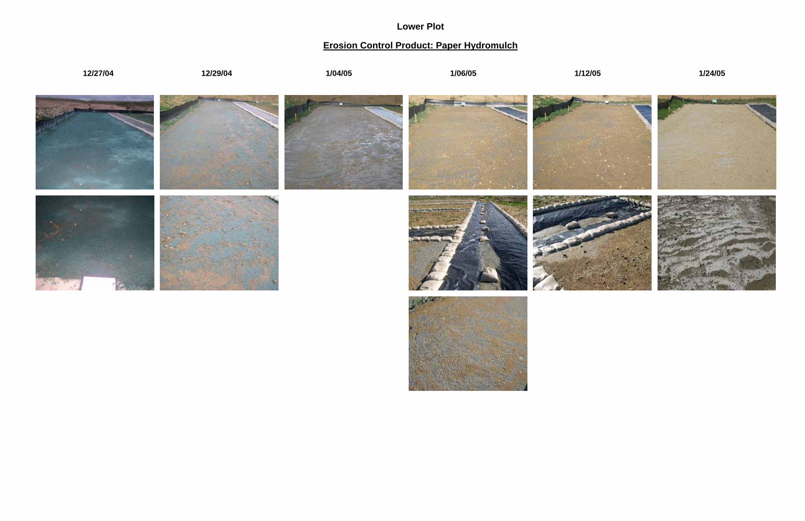
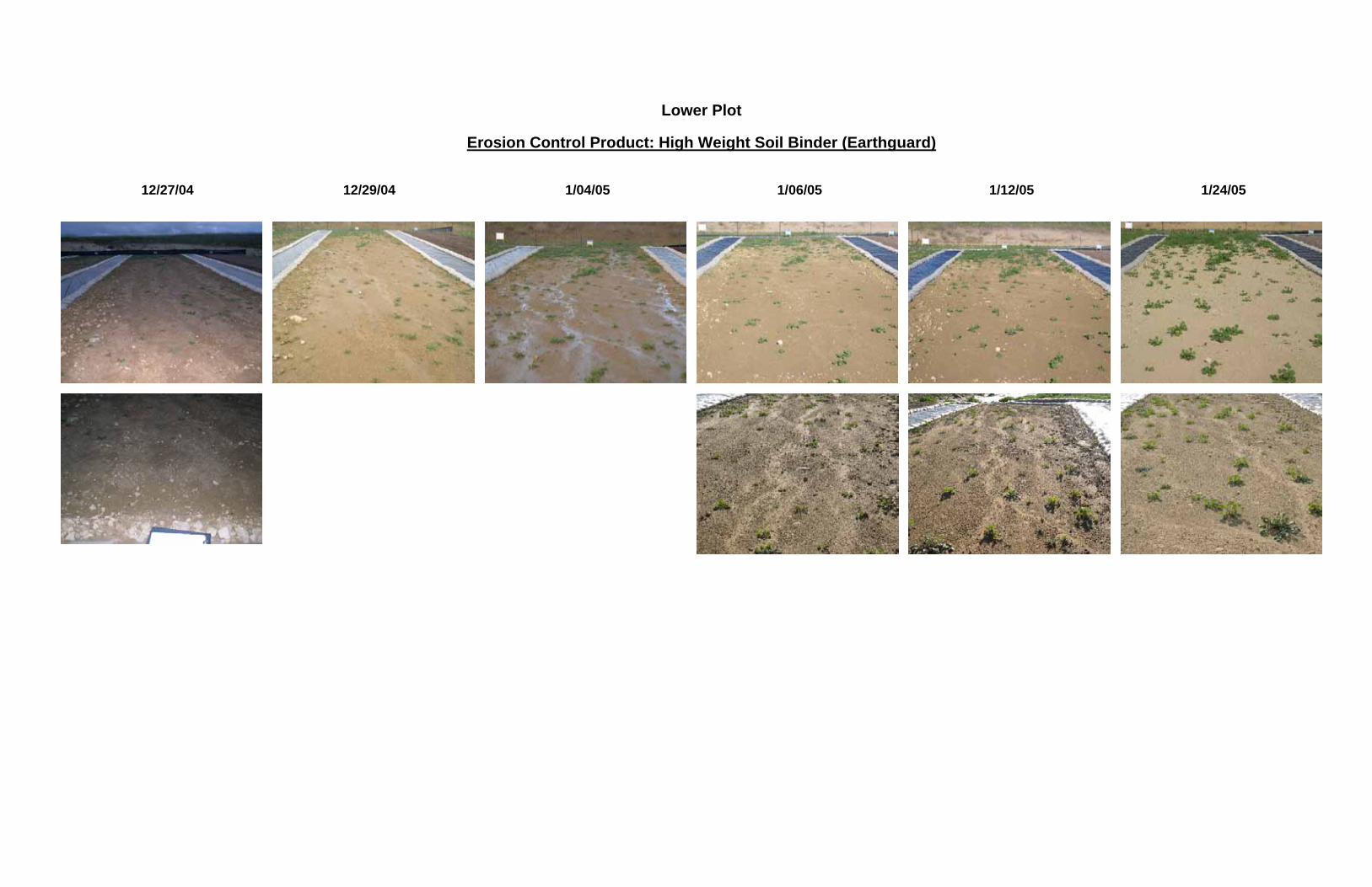
intensities that corresponded to 100-year and 25-year storm event frequencies. It also interesting to note that the 7.47 inches of rainfall recorded for the month of October fell during only the last two weeks of that month. Similarly, over 7 inches of rain fell during the first two weeks of January 2005, and almost 3 inches of rain fell during the last three days of December 2004. However, these storms had lower calculated rainfall intensities than the October events, with a corresponding 2-year storm event frequency for the late December 2004 storm and two events with a 2-year frequency and one event with a 5-year frequency for the early January 2005 storms. 3.2 Visual Monitoring Results The following subsections summarize the observations made during the field study. The observations made during the second application of erosion controls are the most illustrative, and therefore provide the primary basis for the following summary. This is because the period covering the second application received the most rainfall, and all of the erosion control materials for all test plots were installed during this second period. 3.2.1 Lot 15 – 2% (Flat) Slope This section summarizes observations for the test plots on Lot 15, which was the essentially flat pad. Appendix B provides time-series photo progressions for selected dates during this period for the controls summarized below. Low-Weight PAM An application of this control was made on December 27, 2004. By December 29, after two inches of rain had fallen at the site, minor rills were observed, starting about 30 feet from the upper end of the plot and extending the rest of the length of the test plot. After another 2 inches of rain by January 4, more rills were evident, and they started to form at only 10 feet from the top of the test plot. By January 12, almost 10 inches of rain had fallen since the application of this control, and multiple heavy rills were observed on the test plot. In addition, sediment deposits were observed at the lower end of the test plot behind (upstream side) of the gravel bag berm that marked the end of the test plot. After almost 12 inches of rain, multiple significant rills extended the length of the test plot. The vegetation cover was about 5% on the test plot at the time of erosion control application, which increased to about 40-50% before a reapplication of controls. High-Weight PAM This control appeared to behave just as the low-weight PAM, in that the progression, number and extent of rills appeared the same for both of these controls. In fact, some accumulation of sediment at the lower end of this test plot was observed before that on the low-weight test plot.

EROSION CONTROL BMP FIELD EVALUATION
Orange County Storm Water Program 15 January 2007 Erosion Control BMP Field Evaluation
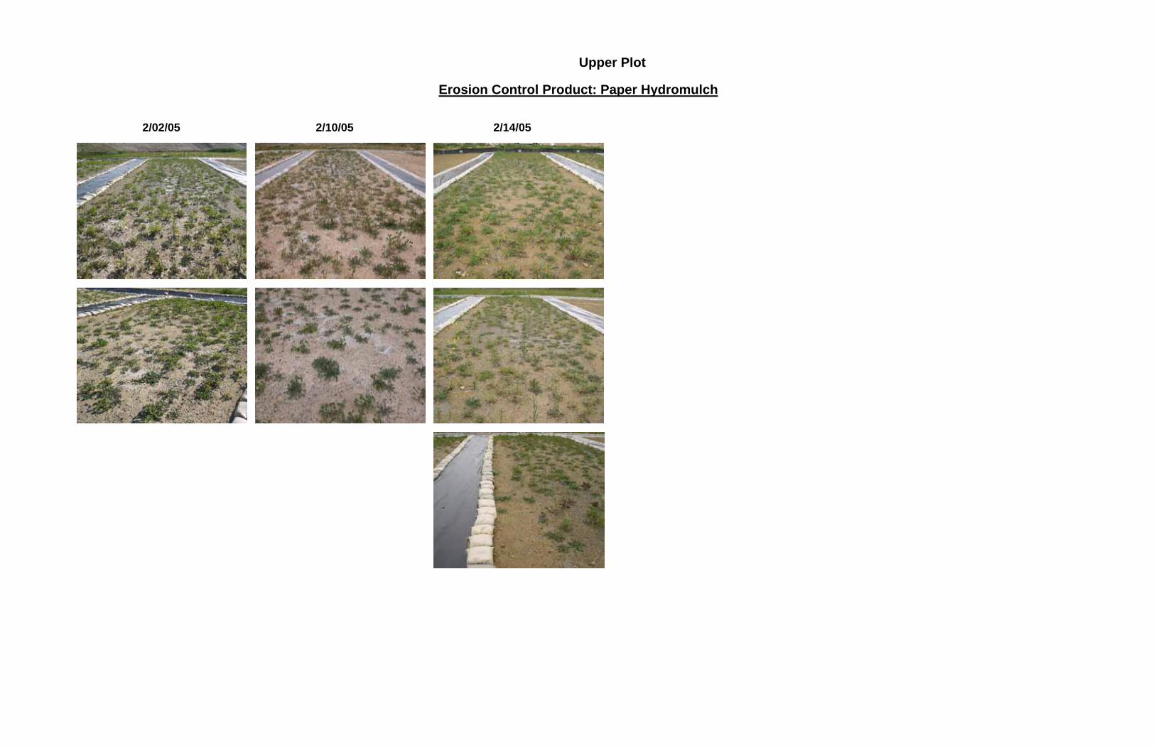
However, there was no gravel bag barrier on one side of this test plot, which may have allowed run-on to this test plot that was not experienced by the low-weight test plot. There was no vegetation cover on this plot throughout this test period. However, this may be related more to the fact that this plot had been entirely covered with plastic sheet up until the start of this test, rather than a result of the erosion control application (note that vegetation did appear on the other high-weight PAM test plots). Paper-Based Hydromulch The application of this control provided 100% coverage of the test plot, but this was reduced to about 50% after 2 inches of rain. After 4 inches of rain, there appeared to be about 30% coverage of the paper mulch, and “waves” of the paper mulch were observed, indicating definite movement of the material. Minor rilling at the edge of the test plot was observed after almost 10 inches of rain. Although difficult to see in the photos, about 25% coverage was observed even after almost 12 inches of rain, although rilling became more pronounced. There was no significant evidence of sediment build up at the lower end of the test plot. The vegetation cover was about 5% on the test plot at the time of erosion control application, which increased to about 30-40% before a reapplication of controls. Wood-Based Hydromulch The application of this control provided 100% coverage of the test plot, which was reduced to about 75% after 2 inches of rain. After 4 inches of rain, there appeared to be about 70% coverage of the wood mulch, and some “waves” of the wood mulch were observed, indicating definite movement of the material. About 50% coverage was observed after almost 12 inches of rain, and the first sign of minor rilling was observed on one side of this test plot. There was no significant evidence of sediment build up at the lower end of the test plot. The vegetation cover was about 5% on the test plot at the time of erosion control application, which increased to about 20% before a reapplication of controls. Wood Mulch This test plot remained 100% covered with the wood mulch throughout the test period, and there was no evidence of movement or migration of the mulch, or evidence of any erosion on the test plot. While vegetation did appear on the other test plots, the wood mulch application prevented any vegetation from appearing. 3.2.2 Lot 14 – 5% (Mild) Slope This section summarizes observations for the test plots on Lot 14, which was the mildly sloping pad. Appendix C provides time-series photo progressions for selected dates during this period for the controls summarized below.

EROSION CONTROL BMP FIELD EVALUATION
Orange County Storm Water Program 16 January 2007 Erosion Control BMP Field Evaluation
Low-Weight PAM An application of this control was made on December 27, 2004. After two inches of rain had fallen at the site, rilling was observed to start at about 20 feet from the upper end of the plot, extending almost the remaining length of the test plot. After another 2 inches of rain by January 4, additional rills were evident, and the initial rills became more pronounced. By January 12, almost 10 inches of rain had fallen since the application of this control, and multiple heavy rills were observed on the test plot. In addition, sediment deposits were observed at the lower end of the test plot behind (upstream side) of the gravel bag berm that marked the end of the test plot. After almost 12 inches of rain, multiple significant rills extended the length of the test plot. The vegetation cover was about 5% on the test plot at the time of erosion control application, which increased to about 60% before a reapplication of controls. High-Weight PAM This control appeared to behave similar to the low-weight PAM, in that the progression, number and extent of rills appeared generally the same for both of these controls, except that rilling started further down the test plot than for the low-weight PAM, and the rills did not become quite as pronounced as for the low-weight PAM. Sediment accumulation at the lower end of the test plot behind the gravel bag berm was not observed. The vegetation cover was less than 5% on this test plot at the time of erosion control application, which increased to about 30% before a reapplication of controls. Paper-Based Hydromulch The application of this control provided near 100% coverage of the test plot, but some areas of slightly “thin” coverage were observed. The coverage was reduced to about 75% after 2 inches of rain, at which point “waves” of the paper mulch were observed, indicating movement of the material. In addition, a single rill was observed in the test plot. After 5 inches of rain, the coverage appeared the same, but additional small rills were observed. After almost 10 inches of rain, the coverage was reduced to 50%, and mulch material was observed in the collection ditch at the base of the test plot. Coverage was reduced to about 40% after almost 12 inches of rain, although rilling became more pronounced, especially on one side of the test plot. Still, there was no evidence of sediment build up at the lower end of the test plot. There was no vegetation cover on this plot throughout this test period, as this test plot had been entirely covered with plastic sheet up until the start of this test. Wood-Based Hydromulch The application of this control provided near 100% coverage of the test plot, but some areas of slightly “thin” coverage were observed. After 2 inches of rain, the coverage was reduced to about 80%, but no discernable evidence of erosion. After 4 inches of rain, there appeared to be

EROSION CONTROL BMP FIELD EVALUATION
Orange County Storm Water Program 17 January 2007 Erosion Control BMP Field Evaluation
about 70% coverage of the wood mulch, and some “waves” of the wood mulch were observed. There appeared to be denser material coverage in the center of the test plot and thinner coverage on the sides. Even after about 12 inches of rain, there appeared to be 70% material coverage, although the first indication of a significant rilling was observed. There was no significant evidence of sediment build up at the lower end of the test plot. The vegetation cover was about 5% on the test plot at the time of erosion control application, which increased to about 30-40% before a reapplication of controls. Wood Mulch This test plot remained 100% covered with the wood mulch throughout the test period, and there was no evidence of movement or migration of the mulch, or evidence of any erosion on the test plot. While vegetation did appear on the other test plots, the wood mulch application generally prevented vegetation from appearing, except for a handful of small weeds. 3.2.3 Slope Area – About 50% Slope This section summarizes observations for the test plots on the slope area, which had an almost 50% slope. Appendix D provides time-series photo progressions for selected dates during this period for the controls summarized below. Low-Weight PAM An application of this control was made on December 27, 2004. After two inches of rain had fallen at the site, rilling was observed to start at about 20 feet from the upper end of the plot, extending the remaining length of the test plot. After another 2 inches of rain by January 4, additional rills were evident, and the initial rills became more pronounced. After almost 10 inches of rain had fallen, a single deep rill developed on one side of the test plot, with additional shallow rills throughout. After almost 12 inches of rain, multiple significant rills extended the length of the test plot. There was very little vegetation cover (less than 5%) on the test plot at the time of erosion control application, which increased only slightly during the test period. High-Weight PAM This control appeared to perform not as well as the low-weight PAM, in that the progression, number and extent of rills appeared to be slightly greater than that for the low-weight PAM. After 2 inches of rain, there was less rilling than that for the low-weight PAM. However, from that point on there appeared to be greater rilling on this plot than the low-weight PAM plot. There was minimal vegetation cover on this plot for the entire duration of this test period.

EROSION CONTROL BMP FIELD EVALUATION
Orange County Storm Water Program 18 January 2007 Erosion Control BMP Field Evaluation
Paper-Based Hydromulch The application of this control provided 100% coverage of the test plot, which was slightly reduced to about 95% coverage after 2 inches of rain. Some minor rilling was also noted near the bottom of the test plot, and “pockets” or depressions were noted, but no significant movement of material was observed. After 5 inches of rain, the coverage was reduced to about 90%. After 10 inches of rain, coverage reduced to about 85% and small rills appeared closer to the top of the test slope. There was no significant vegetation cover on this plot throughout this test period. Wood-Based Hydromulch The application of this control provided 100% coverage of the test plot at the start of the test period. After 10 inches of rain, there still appeared to be about 90% coverage on the slope. Rills did appear, but were generally smaller and less numerous than for the paper hydromulch plot. There was no significant vegetation cover on this plot throughout this test period. Wood Mulch This test plot remained 100% covered with the wood mulch throughout the test period, and there was no evidence of movement or migration of the mulch, or evidence of any erosion on the test plot. Although the test plot photos may suggest material movement as evidenced by the appearance of mounds and depressions, these were caused laborers who periodically walked over the test plot. While vegetation did appear on the other test plots, the wood mulch application generally prevented vegetation from appearing, except for a handful of small weeds.

EROSION CONTROL BMP FIELD EVALUATION
Orange County Storm Water Program 19 January 2007 Erosion Control BMP Field Evaluation
4 Conclusion
4.1 Erosion Control Performance
The relative performance of the selected erosion controls was evaluated qualitatively using the results of the visual monitoring summarized in the previous section. Generally, the five different controls appeared to prevent significant signs of erosion. Based on the observations, however, the different controls did appear to have different life spans, in terms of rainfall amount, for which they appeared to be effective. To establish a basis of comparison for this qualitative study, an erosion control application was deemed to have “failed” when rilling or similar evidence of erosion became visually apparent. The controls performed generally as would be expected, namely that the hydromulches provided effective erosion control for a longer period than the PAM-only test plots. For example, the start of rilling was observed in the PAM test plots after about 2 inches of rain, whereas an equivalent level of rilling was not observed to start in the hydromulch plots until at least 5 inches of rain (for the paper hydromulch on the mildly-sloped pad) and 12 inches of rain (for the wood hydromulch on the mildly-sloped pad). An exception was the wood landscaping mulch (without binder), which performed better than expected on all test plots. This is likely because of the thick application of this control as noted previously. Another exception was with the high-weight PAM on the slope test plot, which appeared to perform worse than the low-weight PAM. Why this was the case is unclear. An inadvertent error may have occurred in applying this control, since the high-weight PAM appeared to perform better than the low-weight PAM during the other test periods. Generally, there did not appear to be a significant difference between the performance of the controls on the flat pad and the mildly-sloping pad, except for the paper hydromulch, which showed evidence of erosion much sooner than for the wood hydromulch on the mildly-sloped pad and slope test plots. That is, the duration that each control (except the paper hydromulch) was effective during the rainfall was very similar between the two test areas. The controls on the slope test plots appeared to perform comparable to the mild/flat test plots for a given duration (observed rainfall amount), although it is important to note that the application rates for the slope test plots were generally twice that of the other test plots, in accordance with manufacturer recommendations and consistent with CASQA guidelines. The observed performance of the erosion controls is summarized in Table 3. Most of the controls did not appear to hinder growth of vegetation. Although seed mix was not added to the controls, new vegetation was observed during the study on all test plots, except for the landscaping mulch plots. At a thickness of about 4-5 inches, the landscaping mulch allowed only a stray weed or two on each test plot.

EROSION CONTROL BMP FIELD EVALUATION
Orange County Storm Water Program 20 January 2007 Erosion Control BMP Field Evaluation
Table 3. Observed Performance of Erosion Control Measures
% Material coverage at incipient failure
Rainfall amount at incipient failure (inches)
Time to incipient failure (days) EC Control
Flat Mild Slope Flat Mild Slope Flat Mild Slope PAM (low weight) N/A1 2 2 2 2 2 2 PAM (high weight) N/A1 2 2 2 2 2 2 Paper Hydromulch 30 75 90 10 5 5 29 9 9 Wood Hydromulch 50 70 90 12 12 10 50 50 19 Landscape Mulch 1002 122 502
1. PAM products were clear, therefore amount of material coverage remaining could not be observed. 2. Landscaping mulch did not fail, and had 100% coverage with no evidence of erosion at the end of the test
period (note that this control was applied at almost 2X the CASQA recommended rate). Based on the findings of this study and other literature, erosion control application guidance was developed and is included in Appendix E. The application guidance included in Appendix E was developed to provide application information based on the findings of this study but also to provide more user-friendly guidance for application of a wide range of erosion control measures.
4.2 Recommendation
The intent of this study was to determine the limits of applicability, primarily based on duration of effectiveness, for selected erosion controls primarily for shorter durations (up to one year). The high amount of rainfall experienced during the study did not allow the opportunity to observe the longevity of the selected controls, in that the effects of weathering/exposure could not be isolated. However, the duration of effectiveness could be tied to the amounts of rainfall experienced at the site during the study. Therefore, based on the observed relative performance of the five controls, an initial recommendation for the use of these controls is summarized in Table 4, where the recommended use for the various controls is a function of the slope and amount of rain expected. Note that while the initial recommendation presented in Table 4 appears to be the same for flat and sloped areas, the application rate for erosion controls on the slope is twice that for the flat areas. Table 4 also includes additional information about the erosion controls that were tested including appropriate site applications, application methods, inspection requirements, and costs. In addition to the controls listed in Table 4 that were evaluated under this study, the County should also allow and encourage use of similar erosion control BMPs such as geotextiles, mats/blankets and plastic sheets. In addition, for disturbed areas that will remain inactive for a year or more, the County should require that seed be added to the hydromulch to establish vegetation for longer-term erosion control. Hydroseeding alone may not be used unless there is sufficient time for vegetation to become established (uniform vegetative coverage of at least 70% of the disturbed area) by October 15. In future erosion control field evaluations landscaping mulch should be applied to a thickness of about 2 to 3

EROSION CONTROL BMP FIELD EVALUATION
Orange County Storm Water Program 21 January 2007 Erosion Control BMP Field Evaluation
inches per the CASQA Construction BMP Handbook guideline for wood mulch. Finally, in addition to landscaping mulch (i.e., without binders), the County should consider allowing the use of similar materials such as yard/green waste, wood waste and compost, as this would promote recycling of these materials.

EROSION CONTROL BMP FIELD EVALUATION
Orange County Storm Water Program 22 January 2007 Erosion Control BMP Field Evaluation
Table 4. Erosion Control Recommendation and Information
Amount Rain / Duration 1
EC Control Flat Area (slope of
5% or less)
Slope Area (slope greater
than 5%)
Appropriate Site Applications Application Methods Inspection
Requirements Costs
PAM (low weight)
1”; 1 storm
Not recommended
Temporary, single storm event; cohesive soils; slope length<500 feet
Dissolve in water, 20 lbs. per 2000 gallons, per acre
After each rain event $1.30 -$5.50/lb (material cost only)
PAM (high weight)
< 2”; 2+ storm 1”; 2+ storm
Temporary, two storm events; cohesive soils; slope length<500 feet
Dissolve in water, 20 lbs. per 2000 gallons, per acre
After each rain event $1.30 -$5.50/lb (material cost only)
Wood Hydromulch 2
<12”; 1 season <12”; 1 season
Steep slopes, steeper than 3:1; high erosion potential slopes; slopes where anchored mulch is needed; disturbed areas where plants slow to develop; stockpiles; slopes adjacent to ESAs
3,000 lb/acre to 4,000 lb/acre based on the manufacturer’s recommendation, 12-24 hours to dry and become effective
Prior to forecast rain, daily during extended rain events, after rain events, weekly during the rainy season, and at two-week intervals during the nonrainy season (nrs)
$6,000 per acre
Landscape Mulch 3
< 12”; 1 season < 12”; 1 season
Flat areas, steep slopes, cohesive soils
Distribute by hand or use pneumatic methods, 2-3-inch depth (thickness) per CASQA guidance
Prior to forecast rain, daily during extended rain events, after rain events, weekly during the rainy season, and at two-week intervals nrs
$4,000 per acre
1 When used per manufacturer recommendations. 2 When used with a high-weight binder. Hydromulch consisting only of paper fiber is not recommended. Wood hydromulch may not contain more than 25% paper fiber. 3 Tested at about 5-inch depth (thickness).

EROSION CONTROL BMP FIELD EVALUATION
Orange County Storm Water Program 23 January 2007 Erosion Control BMP Field Evaluation
4.3 Next Steps
This report was prepared to document the conduct and results of the erosion control study, and to assist the Orange County Stormwater Program in developing a formal preference and/or requirements for use of certain types of erosion controls, along with better field guidance for these preferred erosion control BMPs. Table 4 above is structured as a possible format that the County and Permittees may wish to use for identifying their preferred BMPs for erosion control. However, the next step will be for the Stormwater Permittees, including the NPDES Technical Advisory Committee, to decide how to best structure a preference for certain erosion controls in compliance with the Regional Board requirement to do so.
EROSION CONTROL BMP FIELD EVALUATION
Orange County Storm Water Program 24 January 2007 Erosion Control BMP Field Evaluation
5 References California Regional Water Quality Control Board Santa Ana Region, Order No. R8-2002-0010,
NPDES No. CAS618030. California Storm Water Quality Association (CASQA), 2003. Stormwater Best Management
Practice (BMP) Handbook – Construction, Menlo Park, CA. Caltrans, 2000. District 7 Erosion Control Pilot Study, Report CTSW-RT-00-012, California
Department of Transportation, Sacramento, CA. Caltrans, 2003. Temporary Soil Stabilization Guide, July 2003, California Department of
Transportation, Sacramento, CA. RBF Consulting, 2003. Erosion Control BMP Effectiveness Study, Orange County, CA.

Appendix A:
Erosion Control Study Approval Letter from the Santa Ana Regional Board


Appendix B:
Lot 15 (Flat Slope) Time-Series Photo Progressions

Upper Plot
Erosion Control Product: Wood Hydromulch
12/27/04 12/29/04 1/04/05 1/06/05 1/12/05 1/24/05

Upper Plot
Erosion Control Product: Wood Hydromulch 2/02/05 2/10/05 2/14/05

Upper Plot
Erosion Control Product: Paper Hydromulch
12/27/04 12/29/04 1/04/05 1/06/05 1/12/05 1/24/05
Upper Plot
Erosion Control Product: Paper Hydromulch 2/02/05 2/10/05 2/14/05

Upper Plot
Erosion Control Product: High Weight Soil Binder (Earthguard)
12/27/04 12/29/04 1/04/05 1/06/05 1/12/05 1/24/05

Upper Plot
Erosion Control Product: High Weight Soil Binder (Earthguard) 2/02/05 2/10/05 2/14/05
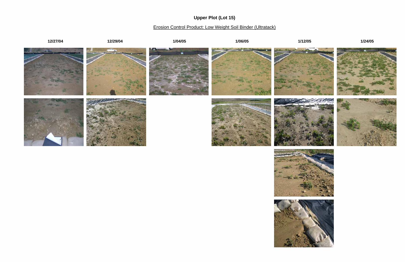
Upper Plot (Lot 15)
Erosion Control Product: Low Weight Soil Binder (Ultratack)
12/27/04 12/29/04 1/04/05 1/06/05 1/12/05 1/24/05
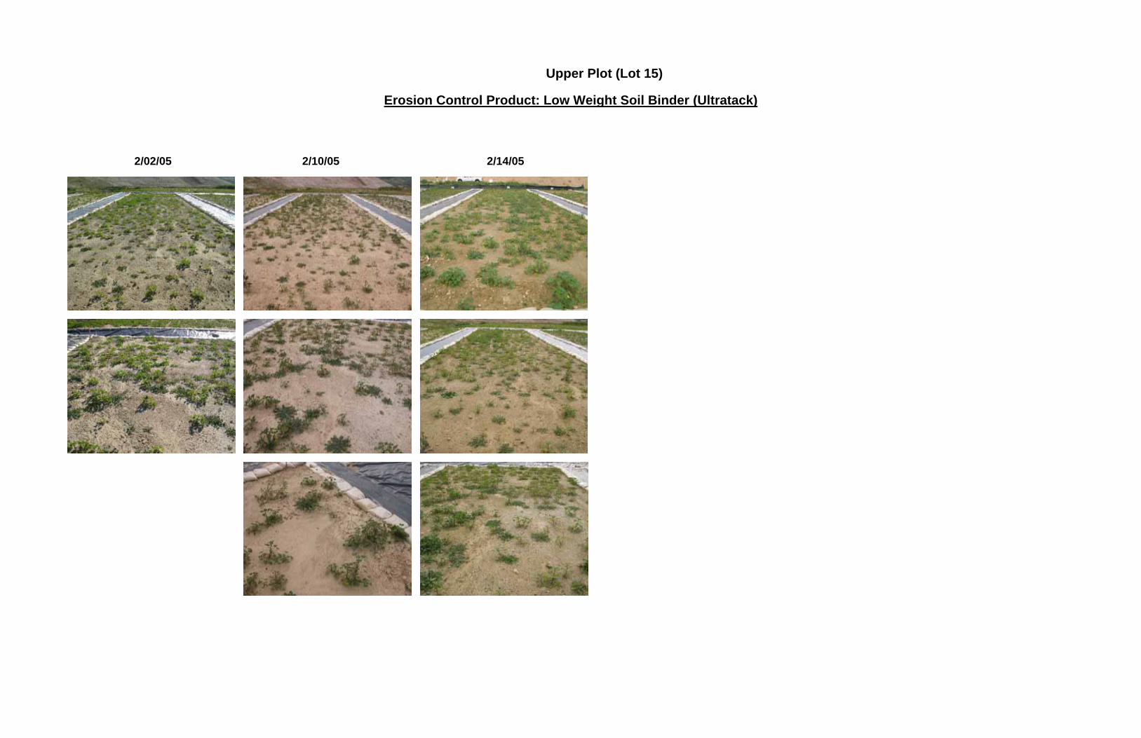
Upper Plot (Lot 15)
Erosion Control Product: Low Weight Soil Binder (Ultratack) 2/02/05 2/10/05 2/14/05

Upper Plot
Erosion Control Product: Wood Mulch 12/27/04 1/12/05 2/2/05 2/14/05

Appendix C:
Lot 14 (Mild Slope) Time-Series Photo Progressions

Lower Plot
Erosion Control Product: Wood Hydromulch
12/27/04 12/29/04 1/04/05 1/06/05 1/12/05 1/24/05

Lower Plot
Erosion Control Product: Wood Hydromulch 2/2/05 2/10/05 2/14/05
Lower Plot
Erosion Control Product: Paper Hydromulch
12/27/04 12/29/04 1/04/05 1/06/05 1/12/05 1/24/05

Lower Plot
Erosion Control Product: Paper Hydromulch 2/2/05 2/10/05 2/14/05
Lower Plot
Erosion Control Product: High Weight Soil Binder (Earthguard)
12/27/04 12/29/04 1/04/05 1/06/05 1/12/05 1/24/05

Lower Plot
Erosion Control Product: High Weight Soil Binder (Earthguard) 2/2/05 2/10/04 2/14/04
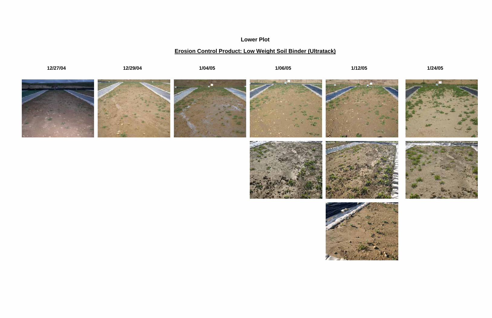
Lower Plot
Erosion Control Product: Low Weight Soil Binder (Ultratack)
12/27/04 12/29/04 1/04/05 1/06/05 1/12/05 1/24/05

Lower Plot
Erosion Control Product: Low Weight Soil Binder (Ultratack) 2/2/05 2/10/04 2/14/04

Lower Plot
Erosion Control Product: Wood Mulch
12/27/04 1/12/05
2/2/05 2/14/05

Appendix D:
Slope Area Time-Series Photo Progressions

Upper Plot
Erosion Control Product: Wood Mulch 12/27/04 1/12/05 1/24/05 2/2/05

Slope Plot
Erosion Control Product: Wood Hydromulch
12/27/04 12/29/04 1/04/05 1/06/05 1/12/05 1/24/05

Slope Plot
Erosion Control Product: Paper Hydromulch
12/27/04 12/29/04 1/04/05 1/06/05 1/12/05 1/24/05

Slope Plot
Erosion Control Product: Paper Hydromulch 2/02/05 2/10/05

Slope Plot
Erosion Control Product: High Weight Soil Binder (Earthguard)
12/27/04 12/29/04 1/04/05 1/06/05 1/12/05 1/24/05

Slope Plot
Erosion Control Product: High Weight Soil Binder (Earthguard) 2/02/05 2/10/05

Slope Plot
Erosion Control Product: Low Weight Soil Binder (Ultratack)
12/27/04 12/29/04 1/04/05 1/06/05 1/12/05 1/24/05

Slope Plot
Erosion Control Product: Low Weight Soil Binder (Ultratack) 2/02/05 2/10/05

Slope Plot
Erosion Control Product: Wood Hydromulch
2/02/05 2/10/05

Appendix E:
Erosion Control Application Guidance

ORANGE COUNTY STORMWATER PROGRAM
Erosion Control Made Simple:
Factsheets for Conditions Commonly Encountered in Southern California
September 2006
A cooperative project between the County of Orange, Orange County Flood Control District and the incorporated cities of Orange County.

Prepared by:
RBF Consulting 14725 Alton Parkway
Irvine, CA 92618
TABLE OF CONTENTS 1 OVERVIEW - WHAT YOU NEED TO SELECT EROSION PROTECTION ................................. 5
1.1 Technical Parameters ..................................................................................................................... 5 1.2 Cost.................................................................................................................................................. 5
2.0 EROSION PROTECTION ................................................................................................................... 6 2.1 Factors Affecting Erosion on Your Site .................................................................................... 6 2.1.1 Slope Length ............................................................................................................................. 6 2.1.2 Slope Steepness......................................................................................................................... 6 2.1.3 Length of Time Protection is Needed........................................................................................ 6 2.1.4 Soil Type ................................................................................................................................... 6 2.2 Erosion Protection Selection .................................................................................................... 7 2.5 Final Selection.......................................................................................................................... 7 2.5.1 Important Product Specifications ............................................................................................. 7
REFERENCES ............................................................................................................................................... 8 CHANNEL STABILIZATION ................................................................................................................... 9
DESCRIPTION OF PROBLEM ......................................................................................................................... 9 APPROPRIATE APPLICATIONS...................................................................................................................... 9 LIMITATIONS............................................................................................................................................... 9 MATERIAL SELECTION.............................................................................................................................. 10 INSTALLATION .......................................................................................................................................... 13 INSPECTION AND MAINTENANCE .............................................................................................................. 15
DRY SEASON STABILIZATION............................................................................................................ 16 DESCRIPTION OF PROBLEM ....................................................................................................................... 16 MEASURES TO REDUCE DUST ON CONSTRUCTION SITES .......................................................................... 16 APPROPRIATE APPLICATIONS FOR SOIL BINDERS ..................................................................................... 19 LIMITATIONS............................................................................................................................................. 19 IMPLEMENTATION..................................................................................................................................... 20
General Considerations....................................................................................................................... 20 Selecting a Dust Control Measure....................................................................................................... 20
APPLICATION OF SOIL BINDERS ................................................................................................................ 29 Soil Binders.......................................................................................................................................... 29 Water ................................................................................................................................................... 29
COSTS ....................................................................................................................................................... 30 INSPECTION AND MAINTENANCE .............................................................................................................. 30 REFERENCES ............................................................................................................................................. 30
SINGLE RAIN EVENT STABILIZATION ............................................................................................ 31 DESCRIPTION OF PROBLEM ....................................................................................................................... 31 APPROPRIATE APPLICATIONS.................................................................................................................... 31 LIMITATIONS............................................................................................................................................. 32 MATERIAL SELECTION.............................................................................................................................. 32 APPLICATION ............................................................................................................................................ 32 INSPECTION AND MAINTENANCE .............................................................................................................. 33
WET SEASON SITE STABILIZATION (COHESIVE SOILS)............................................................ 34 DESCRIPTION OF PROBLEM ....................................................................................................................... 34 APPROPRIATE APPLICATIONS.................................................................................................................... 34 LIMITATIONS............................................................................................................................................. 34 MATERIAL SELECTION.............................................................................................................................. 34 INSTALLATION .......................................................................................................................................... 35 INSPECTION AND MAINTENANCE .............................................................................................................. 35

WET SEASON SITE STABILIZATION (NON-COHESIVE SOILS) ................................................. 37 DESCRIPTION OF PROBLEM ....................................................................................................................... 37 APPROPRIATE APPLICATIONS.................................................................................................................... 37 LIMITATIONS............................................................................................................................................. 38 MATERIAL SELECTION.............................................................................................................................. 38 INSTALLATION .......................................................................................................................................... 40 INSPECTION AND MAINTENANCE .............................................................................................................. 42
PERMANENT STABILIZATION ........................................................................................................... 43 DESCRIPTION OF PROBLEM ....................................................................................................................... 43 APPROPRIATE APPLICATIONS.................................................................................................................... 43 LIMITATIONS............................................................................................................................................. 44 MATERIAL SELECTION.............................................................................................................................. 44 INSTALLATION .......................................................................................................................................... 44 INSPECTION AND MAINTENANCE .............................................................................................................. 46
1 Overview - What You Need to Select Erosion Protection
Erosion protection for a construction site is required as a part of the State General Construction Permit. The permit requires that permitees, at a minimum, “…implement an effective combination of erosion and sediment control on all disturbed areas during the rainy season.” Further, the permit requires that the discharger, “…must consider the full range of erosion control BMPs. The discharger must consider any additional site-specific and seasonal conditions when selecting and implementing appropriate BMPs.” The general purpose of this fact sheet is to ensure that your construction site is in compliance with the General Permit and Orange County requirements. There are many erosion control products available, from spray-on applications to blankets and matting. Product pricing and installation cost also varies widely. Selecting the most appropriate erosion control product with consideration to minimizing cost is the goal of this fact sheet. Your site will not be in compliance with the General Permit if you do not have erosion protection for all exposed areas when a rain event occurs. You are responsible for ensuring erosion protection regardless of the time of year, day of the week, phase of work or site conditions. The permit requires a general schedule for erosion control applications to demonstrate that a plan of attack has been developed and that you will be ready for the next rainfall.
1.1 Technical Parameters The rate of erosion for a given plot of land is affected by rainfall intensity, the soil type, the land slope and slope length, and the erosion protection. All erosion control products will prevent erosion, but will vary in their effectiveness based on the factors that influence erosion, and the amount of time that erosion protection is required. For example, the same erosion control product would not be used on an embankment stockpile (temporary) as would be used on a final graded slope (permanent). These fact sheets will help you select an appropriate erosion control measure for your site based on the site specific conditions.
1.2 Cost Cost is a primary driver in the selection of an erosion control product. Erosion control will have to be applied many times throughout the life of the construction project. Therefore, it is important to select the most economical product that will provide the required protection for the needed lifespan. The cost of erosion control products applied to an acre of land can vary from a few hundred dollars per acre to over ten thousand dollars per acre. It can be tempting to select the most inexpensive product regardless of site conditions, assuming that the General Permit is satisfied by ‘doing something’. Technology, and regulatory oversight have both become more sophisticated in recent years making the

‘do something’ strategy obsolete. Contemporary site compliance is achieved using a well planned strategy and careful implementation.
2.0 Erosion Protection
2.1 Factors Affecting Erosion on Your Site There are several factors that affect erosion on a construction site. Some of these factors will be more important than others in selecting an erosion control product. The first three factors are by far the most important, and for practical purposes, equally important.
2.1.1 Slope Length The length of the slope, or surface that the runoff flows over is important since the amount of erosion is proportional to the velocity of the water. Generally the more water (depth) that flows over a surface, the greater its velocity. Erosion can be reduced by reducing slope length. Plans often call for terrace drains in engineered slopes to reduce the slope length. During construction, slope length can be reduced by using fiber rolls. For the purposes of these fact sheets, the longer the slope, the more robust the erosion protection must be.
2.1.2 Slope Steepness The gradient of the slope will also impact the velocity of the runoff flowing over the surface. A steeper slope will have higher runoff velocities and greater erosion. There is little that can be done to reduce slope steepness in the field. Track walking is a way to slow flow velocity without changing the overall gradient of the slope. In general however, the steeper the slope, the more robust the erosion protection must be.
2.1.3 Length of Time Protection is Needed Some erosion control materials, such as PAM, have a limited useful life and will not stand up to surface traffic. Generally, an erosion control products can be segregated into three broad categories with respect to useful lifespan:
1. Single storm event 2. One rainy season 3. Permanent stabilization
The price of erosion control products increases with the product life span. The cost of a binder with a life span of a single rain event is about $400 per acre. The cost of permanent stabilization can range as high as $50,000 per acre for a bonded synthetic fiber product.
2.1.4 Soil Type Each soil type has an inherent erosion potential that varies with the specific soil structure. This potential is a function of the permeability, particle size distribution and amount of organic matter present. Undisturbed soils have a greater resistance to erosion than disturbed soils. Unless site soils are highly resistant to erosion, this parameter is generally not important enough to consider in the selection of an erosion

control product. An estimate of the erosion potential of the site soils should be provided in the geotechnical investigation.
2.2 Erosion Protection Selection Each of the erosion control fact sheets describes a situation typically encountered during the construction process. The appropriate fact sheet for your situation is based on the length of time that protection is needed (single storm event, rainy season, or permanent) and the steepness of the slope. A ‘short list’ of suitable products is identified and instructions are provided for installation and any special considerations that might be appropriate are described. This short list of materials should be refined using the following procedure: • Manufacturer should be consulted (as appropriate) for opinion as to the application
for the specific situation • Product availability should be checked, including installation and curing times • Most robust product should be selected (least technical application and curing
requirements) • Product with the least cost that meets above requirements should be selected The fact sheets will generally identify the product that will meet ‘best conventional technology’ standard requirements for the least cost. Final costing of the selected alternatives, as well as investigation of specific installation requirements will be the responsibility of the user. Information in the fact sheets will provide guidance for sites with highly erosion-resistant soils; otherwise, soil erosion potential is not a critical decision factor.
2.5 Final Selection Once the list of products has been narrowed to a few candidates, the final selection should be made, all other things being equal, based on price. If the product does not perform well following installation, an alternative product should be selected when similar conditions are encountered in the future.
2.5.1 Important Product Specifications When applying erosion control products, reviewing the product specifications and installation guidelines are critical to ensure performance. Below is a suggested checklist: Hydraulic Mulches (including BFM)
• Require 24 hours curing time prior to rain to be effective • Surface should be roughened prior to installation (punch type roller)
Hydroseed
• Roughen area prior to application • Do not apply if there is not a likelihood of rain within 1 month of application • Apply blanket of straw over hydroseed to protect seeds and retain moisture • Use the minimum amount of fertilizer recommended by the manufacturer

• Hydroseed is not a temporary erosion control Soil Binders
• Soil binders are for temporary stabilization only • Require a minimum curing time of 24 - 48 hours to be effective • Can not take surface traffic • A sampling/analysis plan must be instituted if soil binders are used since they may
be a source of non-visible pollutants • Soil should not be compacted if possible prior to application • Soil binders that are know to be toxic may not be used • Area should be pre-wet prior to binder application
Straw Mulch
• Straw must be punched or bound together with a tackifier • Do not use in windy areas • Punching is ineffective with very sandy soils • Straw should be from wheat, rice or barley • Straw is flammable and can be a fire hazard, consider other materials during fire
season • Roughen surface with roller prior to installation
Geotextiles
• Suitable for steep slopes • Do not roughen surface, compacted, smooth surfaces are best • Fabric must come into contact with soil on a consistent basis or erosion under the
mat will occur • Synthetic mats may not remain in place as a permanent measure since they do not
degrade, biodegradable rolled products are preferred such as jute, wood, straws or coconut fiber. An exception is in channels, where the mat may remain as a permanent lining to stabilize vegetation.
References CASQA, 2003, Stormwater Best Management Practice Handbook: Construction, Menlo Park, CA.
TTI, 2001, Field Performance Testing of Selected Erosion Control Products Final Performance Analysis through the 2001 Evaluation Cycle, Texas A&M University. (http://www.dot.state.tx.us/insdtdot/orgchart/cmd/erosion/contents.htm)

Channel Stabilization
Description of Problem Many construction projects include the construction of natural channels to temporarily control runoff during the construction phase or as permanent conveyance systems for the completed development. These channels are often highly unstable and require immediate stabilization. They can be stabilized with the use of sod at mild slopes or there are a variety of mats and blankets that are recommended or have been tested for stabilization of natural channels. These mats are made of natural or synthetic material, which are used to temporarily or permanently stabilize soil, help establish vegetation, and protect soil from erosion by wind or water.
The objective of this section is to describe how to select and install the appropriate channel stabilization material for your site. This information is based on guidance provided in the CASQA Construction BMP Manual (2003) and supplemented by other sources.
Appropriate Applications Mattings are also used on newly constructed channels and stream banks where moving water at velocities between 3 fps and 6 fps are likely to wash out new vegetation. Erosion control matting should be considered when the soils are fine-grained and potentially erosive. These measures should be considered in the following situations.
• Channels with flows exceeding 1.0 m/s (3.3 ft/s).
• Channels intended to be vegetated.
Limitations • Properly installed mats and blankets provide excellent erosion control but do so at
relatively high cost. This high cost typically limits the use of these materials to areas of concentrated channel flow and steep slopes.
• Installation is critical and requires experienced contractors. The contractor should install the matting material in such a manner that continuous contact between the material and the soil occurs, otherwise the material will not stabilize the soil strengths and uses vary; the manufacturers specifications should be followed.
• May delay seed germination, due to reduction in soil temperature.
• Installation requires experienced contractor to ensure soil stabilization and erosion protection.

Material Selection The selection of the proper channel lining material is based on the ability of the material to resist the shear stress applied to the channel bottom and walls by the overlying water, and by its ability to allow vegetation establishment to further stabilize the channel. Shear stress for straight channels is calculated as:
τ = γRSf Where: τ = sheer stress (lbs/ft2 or Pa) γ = specific weight of water (about 62.2 lbs/ft3 or 9780 N/m3) R = hydraulic radius (cross-sectional area/wetted perimeter) Sf = channel slope In general, trapezoidal channels less than 10 feet wide and with slopes of below 2% experience sheer stresses of less than 2 lb/ft2. Increasing the slope to about 5% results in sheer stresses of about 4 lb/ft2. These stresses are greater where channels change direction. The Texas Department of Transportation has funded the testing of a variety of materials for channel stabilization at the Texas Transportation Institute and has developed an approved product list that is available on their website (http://www.dot.state.tx.us/insdtdot/orgchart/cmd/erosion/contents.htm). Approval requires the ability to promote vegetation growth and withstand sheer stresses applied in a test channel. The current approved product list is shown below, but other equivalent products would be acceptable as well.

TxDOT APPROVED PRODUCT LIST for CHANNEL LINING Effective Date: October 4, 2001
Type E - Shear Stress Range 0 - 96 Pascal (0 - 2 Pounds Per Square Foot): Contech TRM C-45 Contech C-35 Contech C50 Contech Coconut/Poly Fiber Mat Contech Coconut Mat w/Kraft Net Curlex II Stitched Curlex III Stitched Curlex® Channel Enforcer 1 Curlex® Channel Enforcer II Earth-Lock Earth-Lock II ECS High Impact Excelsior ECS Standard Excelsior ECS High Velocity Straw Mat Enkamat 7018 Enkamat 7020 Enkamat Composite 30 Enviromat Geotech TechMat™ CP 3-D Geotech TechMat™ CKN Greenfix CFO 72RR Greenstreak Pec-Mat
Koirmat 700 Landlok® BonTerra C2 Landlok® BonTerra® CP2 Landlok® BonTerra® EcoNet™ ENC2 Landlok® BonTerra SFBLandlok® BonTerra SFB12 Landlok TRM 435 Landlok TRM 450 Landlok TRM 1050 Landlok TRM 1060 Maccaferri MX287 Miramat TM8 Multimat 100 North American Green C125 BN North American Green C350 Three Phase North American Green SC150 BN North American Green S350 North American Green® P350 North American Green S150 PyramatWebtec Terraguard 44P Webtec Terraguard 45P Xcel PP-5
Type F - Shear Stress Range 0 - 192 Pascal (0 - 4 Pounds Per Square Foot): Curlex II Stitched Curlex III Stitched Curlex® Channel Enforcer 1 Curlex® Channel Enforcer II Contech C50 Contech TRM C-45 Contech C-35 Contech Coconut/Poly Fiber Mat Contech Coconut Mat w/Kraft Net Earth-Lock Earth-Lock II ECS High Impact Excelsior ECS High Velocity Straw Mat ECS Standard Excelsior Enkamat 7018 Enkamat Composite 30 Enviromat Geotech TechMat™ CP 3-D Geotech TechMat™ CKN Greenfix CFO 72RR Greenstreak Pec-Mat Koirmat 700
Landlok® BonTerra C2 Landlok® BonTerra® CP2 Landlok® BonTerra® EcoNet™ ENC2 Landlok BonTerra SFBLandlok BonTerra SFB12 Landlok TRM 435 Landlok TRM 450 Landlok TRM 1050 Landlok TRM 1060 Maccaferri MX287 Miramat TM8 Multimat 100 North American Green C125 BN North American Green C350 Three Phase North American Green SC150 BN North American Green S350 North American Green® P350 North American Green S150 PyramatWebtec Terraguard 44P Webtec Terraguard 45P Xcel PP-5

Type G - Shear Stress Range 0 - 287 Pascal (0 - 6 Pounds Per Square Foot): Contech TRM C-45 Contech C-35 Contech C50 Contech Coconut/Poly Fiber Mat Curlex III Stitched Curlex® Channel Enforcer II Earth-Lock Earth-Lock II Enkamat 7018 Enkamat Composite 30 Geotech TechMat™ CP 3-D Greenstreak Pec-Mat Koirmat 700
Landlok® BonTerra® CP2 Landlok® BonTerra SFBLandlok® BonTerra SFB12 Landlok TRM 1050 Landlok TRM 1060 Landlok TRM 435 Landlok TRM 450 North American Green C350 Three Phase North American Green S350 North American Green® P350 PyramatWebtec Terraguard 44P Webtec Terraguard 45P
Type H - Shear Stress Range 0 - 383 Pascal (0 - 8 Pounds Per Square Foot): Contech TRM C-45 Contech C-35 Contech C50 Contech Coconut/Poly Fiber Mat Curlex III Stitched Geotech TechMat™ CP 3-D Landlok® BonTerra SFB12 Landlok TRM 435 Landlok TRM 450 Landlok TRM 1050 Landlok TRM 1060 North American Green C350 Three Phase North American Green S350 North American Green® P350 PyramatWebtec Terraguard 44P Webtec Terraguard 45P

Installation Site Preparation
• Proper site preparation is essential to ensure complete contact of the blanket or matting with the soil.
• Grade and shape the area of installation.
• Remove all rocks, clods, vegetation or other obstructions so that the installed blankets or mats will have complete, direct contact with the soil.
• Prepare seedbed by loosening 50 mm (2 in) to 75 mm (3 in) of topsoil.
Seeding Seed the area before blanket installation for erosion control and revegetation. Seeding after mat installation is often specified for turf reinforcement application. When seeding prior to blanket installation, all check slots and other areas disturbed during installation must be re-seeded. Where soil filling is specified, seed the matting and the entire disturbed area after installation and prior to filling the mat with soil.
Fertilize and seed in accordance with seeding specifications or other types of landscaping plans. When using jute matting on a seeded area, apply approximately half the seed before laying the mat and the remainder after laying the mat. The protective matting can be laid over areas where grass has been planted and the seedlings have emerged. Where vines or other ground covers are to be planted, lay the protective matting first and then plant through matting according to design of planting.
Erosion Stops Erosion stops are made of glass fiber strips, excelsior matting strips or tight-folded jute matting blanket or strips for use on steep, highly erodible watercourses. The stops are placed in narrow trenches six to twelve inches deep across the channel and left flush with the soil surface. They are to cover the full cross section of designed flow.
General Guidance • Before laying the matting, all erosion stops should be installed and the friable
seedbed made free from clods, rocks, and roots. The surface upon which the separation fabric will be placed should be compacted and finished according to the requirements of the manufacturer’s recommendations.
• Most matting comes with the manufacturer’s recommendations for installation. Most channels will require multiple widths of matting, and the matting should be unrolled starting at the upper end of the channel, allowing a four-inch overlap of mattings along the center of the channel. To secure, bury the top ends of the matting in narrow trench, a minimum of six inches deep. Back fill trench and tamp firmly to conform to channel cross section. Secure with a row of staples about four inches down slope from the trench with staples twelve inches apart.
• Where matting crosses erosion stops, reinforce with a double row of staples at six inch spacing, using a staggered pattern on either side of the erosion stop. When

the matting is overlapped, the discharge end of the matting liner should be similarly secured with a double row of staples.
• Mechanical or manual lay down equipment should be capable of handling full rolls of fabric, and laying the fabric smoothly, without wrinkles or folds. The equipment should meet the fabric manufacturer’s recommendations or equivalent standards.
Detailed Guidance Always consult the manufacturer's recommendations for installation. In general, these will be as follows:
• Dig initial anchor trench 300 mm (12 in) deep and 150 mm (6 in) wide across the channel at the lower end of the project area.
• Excavate intermittent check slots, 150 mm (6 in) deep and 150 mm (6 in) wide across the channel at 8 m to 10 m (25 ft to 30 ft) intervals along the channels.
• Cut longitudinal channel anchor slots 100 mm (4 in) deep and 100 mm (4 in) wide along each side of the installation to bury edges of matting, whenever possible extend matting 50 mm (2 in) to 75 mm (3 in) above the crest of the channel side slopes.
• Beginning at the downstream end and in the center of the channel, place the initial end of the first roll in the anchor trench and secure with fastening devices at 300 mm (12 in) intervals. Note: matting will initially be upside down in anchor trench.
• In the same manner, position adjacent rolls in anchor trench, overlapping the preceding roll a minimum of 75 mm (3 in).
• Secure these initial ends of mats with anchors at 300 mm (12 in) intervals, backfill and compact soil.
• Unroll center strip of matting upstream. Stop at next check slot or terminal anchor trench. Unroll adjacent mats upstream in similar fashion, maintaining a 75 mm (3 in) overlap.
• Fold and secure all rolls of matting snugly into all transverse check slots. Lay mat in the bottom of the slot then fold back against itself. Anchor through both layers of mat at 300 mm (12 in) intervals, then backfill and compact soil. Continue rolling all mat widths upstream to the next check slot or terminal anchor trench.
• Alternate method for non-critical installations: Place two rows of anchors on 150 mm (6 in) centers at 8 m (25 ft) to 10 m (30 ft) intervals in lieu of excavated check slots.
• Shingle-lap spliced ends by a minimum of 300 mm (12 in) apart on 300 mm (12 in) intervals.
• Place edges of outside mats in previously excavated longitudinal slots, anchor using prescribed staple pattern, backfill and compact soil.

• Anchor, fill and compact upstream end of mat in a 300 mm (12 in) by 150 mm (6 in) terminal trench.
• Secure mat to ground surface using U-shaped wire staples, geotextile pins, or wooden stakes.
• Seed and fill turf reinforcement matting with soil, if specified.
Anchoring • U-shaped wire staples should be used to anchor mats and blankets to the ground
surface.
• Staples shall be made of 3.05 mm steel wire and shall be U-shaped with 200-mm legs and 50-mm crown. Wire staples shall be minimum of 11 gauge.
• Wire staples shall be driven flush to the soil surface.
Inspection and Maintenance Maintenance items for channel stabilization include:
• All blankets and mats should be inspected periodically after installation.
• Installation shall be inspected after significant rain storms to check for erosion and undermining. Any failures should be repaired immediately.
• If washout or breakage occurs, re-install the material after repairing the damage to the channel.
• Make sure matting is uniformly in contact with the soil.
• Check that all the lap joints are secure.
• Check that staples are flush with the ground.
• Check that disturbed areas are seeded.

Dry Season Stabilization
Description of Problem Stabilization of construction projects during the dry season is common component of SWPPP. One of the main of objectives of this practice is to prevent wind erosion and deposition of sediment on adjacent properties. Wind erosion or dust control consists of various management practices including applying water or other chemicals as necessary to prevent or alleviate dust nuisance generated by construction activities. Covering small stockpiles or areas is an alternative to applying water or other dust palliatives. Water application is an obvious and common solution to wind erosion problems, so this fact sheet focuses various on other measures and materials, such as soil binders, that are appropriate for application on bare soils. Soil binders consist of applying and maintaining polymeric or lignin sulfonate soil stabilizers or emulsions. Soil binders typically provide dust, wind and soil stabilization (erosion control) benefits.
Measures to Reduce Dust on Construction Sites Tables 1 through 6 contain descriptions of various alternatives for dust control based on the type of the activity occurring at the site. These alternatives, which were developed by the Pima County AZ, DEQ, include the use of water, chemical stabilizers, and other measures as appropriate.
Table 1 Land Clearing Activities
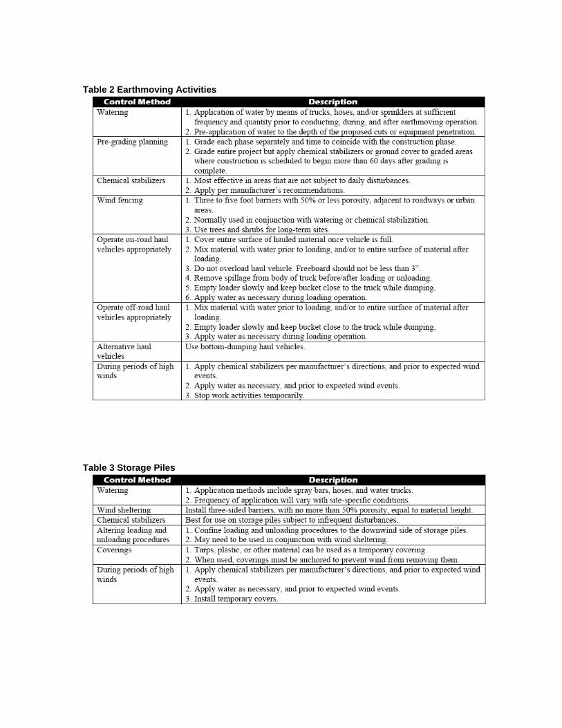
Table 2 Earthmoving Activities
Table 3 Storage Piles
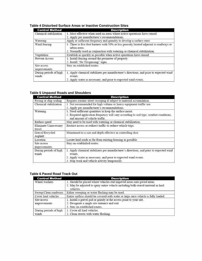
Table 4 Disturbed Surface Areas or Inactive Construction Sites
Table 5 Unpaved Roads and Shoulders
Table 6 Paved Road Track Out

Appropriate Applications for Soil Binders The use of soil binders is quite common for dust control on construction sites; however, they must be appropriate for conditions on the site and be properly applied. Because soil binders can often be incorporated into the work, they may be a good choice for areas where grading activities will soon resume. Soil binders are suitable during the following construction activities:
• Construction vehicle traffic on unpaved roads
• Drilling and blasting activities
• Sediment tracking onto paved roads
• Soils and debris storage piles
• Batch drop from front-end loaders
• Areas with unstabilized soil
• Final grading/site stabilization
Limitations • Soil binders are temporary in nature and may need reapplication.
• Soil binders require a minimum curing time until fully effective, as prescribed by the manufacturer, which may be 24 hours or longer.
• Soil binders will generally experience spot failures during heavy rainfall events. If runoff penetrates the soil at the top of a slope treated with a soil binder, it is likely that the runoff will undercut the stabilized soil layer and discharge at a point further down slope.
• Soil binders do not hold up to pedestrian or vehicular traffic across treated areas.
• Soil binders may not penetrate soil surfaces made up primarily of silt and clay, particularly when compacted.
• Some soil binders may not perform well with low relative humidity. Under
• Rainy conditions, some agents may become slippery or leach out of the soil.
• May not cure if low temperatures occur within 24 hours of application

Implementation
General Considerations • Regional soil types will dictate appropriate soil binders to be used.
• If a soil binder is selected, it must be environmentally benign (non-toxic to plant and animal life), easy to apply, easy to maintain, economical, and shall not stain paved or painted surfaces.
• Measures implemented should be compatible with existing vegetation.
• Performance of dust control measures depends on temperature, humidity, and traffic across treated areas.
Selecting a Dust Control Measure Factors to consider when selecting a measure include the following:
• Suitability to situation – If a soil binder will be applied; if it needs a high resistance to leaching or abrasion, and whether it needs to be compatible with any existing vegetation. Determine the length of time soil stabilization will be needed, and if the soil binder will be placed in an area where it will degrade rapidly. In general, slope steepness is not a discriminating factor for the listed soil binders
• Soil types and surface materials - Fines and moisture content are key properties of surface materials. Consider a soil binder's ability to penetrate, likelihood of leaching, and ability to form a surface crust on the surface materials.
• Frequency of application - The frequency of application can be affected by sub grade conditions, surface type, climate, and maintenance schedule. Frequent applications could lead to high costs. Application frequency may be minimized if the soil binder has good penetration, low evaporation, and good longevity. Consider also that frequent application will require frequent equipment clean up.
Suggested products for various soil types and traffic volumes are described in Table 7. This table describes the appropriate soil types and traffic levels for various products. The properties of each of these binders is described in detail in Table 8, while contact information for manufacturer’s of these products is provided in Table 9.

Table 7 Product Selection Chart

Table 8 Properties and Uses of Various Soil Binders
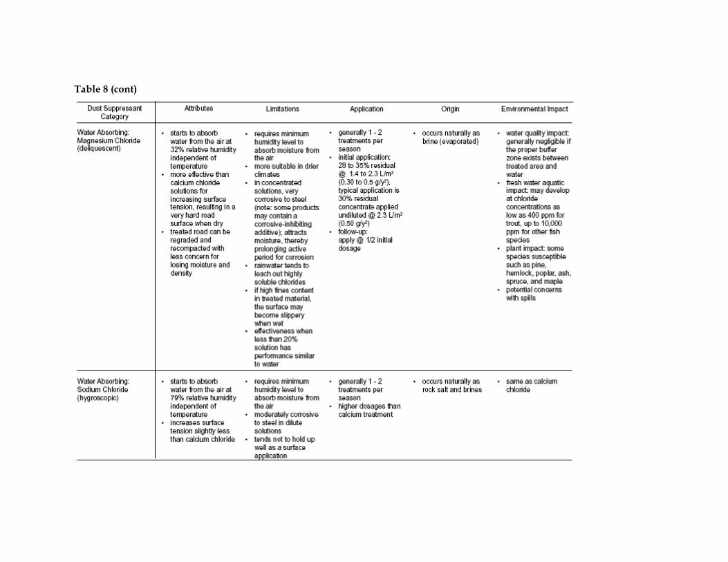
Table 8 (cont)

Table 8 (cont)

Table 8 (cont)

Table 8 (cont)

Table 9 Manufacturer’s of Soil Binders

Table 9 (cont)

Application of Soil Binders
Soil Binders After selecting an appropriate soil binder, the untreated soil surface must be prepared before applying the soil binder. The untreated soil surface must contain sufficient moisture to assist the agent in achieving uniform distribution. In general, the following steps shall be followed:
• Follow manufacturer’s recommendations for application rates, pre-wetting of application area, and cleaning of equipment after use.
• Prior to application, roughen embankment and fill areas. Track walking shall only be used where rolling is impractical.
• Consider the drying time for the selected soil binder and apply with sufficient time before anticipated rainfall. Soil binders shall not be applied during or immediately before rainfall.
• Avoid over-spray onto the traveled way, sidewalks, lined drainage channels, sound walls, and existing vegetation.
• Soil binders shall not be applied to frozen soil, areas with standing water, under freezing or rainy conditions, or when the temperature is below 4oC (40oF) during the curing period.
• More than one treatment is often necessary, although the second treatment may be diluted or have a lower application rate.
• Generally, soil binders require a minimum curing time of 24 hours before they are fully effective. Refer to manufacturer's instructions for specific cure time; and-
• For liquid agents:
- Crown or slope ground to avoid ponding.
- Uniformly pre-wet ground at 0.14 to 1.4 l/m2 (0.03 to 0.3 gal/yd2) or according to manufacturer’s recommendations.
- Apply solution under pressure. Overlap solution 150 to 300 mm (6 to 12 in).
- Allow treated area to cure for the time recommended by the manufacturer; typically, at least 24 hours.
- Apply second treatment before first treatment becomes ineffective, using 50% application rate.
- In low humidities, reactivate chemicals by re-wetting with water at 0.5 to 0.9 l/m2 (0.1 to 0.2 gal/yd2).
Water • Water should be applied by means of pressure-type distributors or pipelines
equipped with a spray system or hoses and nozzles that will ensure even distribution.

• Unless water is applied by means of pipelines, at least one mobile unit should be available at all times to apply water or dust palliative to the project.
• If reclaimed waste water is used, the sources and discharge must meet California Department of Health Services water reclamation criteria and the Regional Water Quality Control Board requirements. Non-potable water should not be conveyed in tanks or drain pipes that will be used to convey potable water and there should be no connection between potable and non-potable supplies. Non-potable tanks, pipes, and other conveyances should be marked, “NON-POTABLE WATER - DO NOT DRINK.”
Costs Installation costs for water and chemical dust suppression are low, but annual costs may be quite high since these measures are effective for only a few hours to a few days.
Inspection and Maintenance • Inspect and verify that activity-based BMPs are in place prior to the commencement
of associated activities. While activities associated with the BMP are under way, inspect at two-week intervals in the dry season to verify continued BMP implementation.
• Check areas protected to ensure coverage.
• Most dust control measures require frequent, often daily, or multiple times per day attention.
References Best Management Practices and Erosion Control Manual for Construction Sites, Flood Control District of Maricopa County, Arizona, September 1992.
California Air Pollution Control Laws, California Air Resources Board, 1992.
Caltrans, Standard Specifications, Sections 10, “Dust Control”; Section 17, “Watering”; and Section 18, “Dust Palliative”.
Prospects for Attaining the State Ambient Air Quality Standards for Suspended Particulate Matter (PM10), Visibility Reducing Particles, Sulfates, Lead, and Hydrogen Sulfide, California Air Resources Board, April 1991.
Stormwater Quality Handbooks Construction Site Best Management Practices (BMPs) Manual, State of California Department of Transportation (Caltrans), November 2000.

Single Rain Event Stabilization
Description of Problem During the course of construction projects temporary stabilization is often needed during the wet season on portions of the site where grading and other activities are still occurring. The objective of this sheet is to provide guidance on the selection of measures that are cost effective to prevent erosion during a single event in an area with non-cohesive soils, when construction will resume when weather conditions permit.
Appropriate Applications One of the most cost effective materials for very short term erosion control on fairly flat slopes is polyacrylamide (PAM). PAM is a chemical that can be applied to disturbed oils at construction sites to reduce erosion and improve settling of suspended sediment. PAM increases the soil’s available pore volume, thus increasing infiltration and reducing the quantity of stormwater runoff that can cause erosion. Suspended sediments from PAM treated soils exhibit increased flocculation over untreated soils. The increased flocculation aids in their deposition, thus reducing stormwater runoff turbidity and improving water quality. The appropriate applications are defined by the length of the slope, the type of soil and the length of time that erosion protection is desired.
• Use for temporary erosion control for single storm event when construction activities will resume when weather permits
• Works best on the cohesive soils found in the upland areas of Orange County
• Slopes of less than 5%
• Length of slope less than 150 feet.

Limitations • PAM shall not be directly applied to water or allowed to enter a water body.
• Do not use PAM on a slope that flows into a water body without passing through a sediment trap or sediment basin.
• PAM will work when applied to saturated soil but is not as effective as applications to dry or damp soil.
• A sampling and analysis plan must be incorporated into the SWPPP as PAM may be considered to be a source of non-visible pollutants.
Material Selection
• On slopes greater than 5% only high molecular weight PAM should be used.
• On slopes of less than 5% either low or high molecular weight PAM is appropriate.
• Some PAMs are more toxic and carcinogenic than others. Only the most environmentally safe PAM products should be used.
• The specific PAM copolymer formulation must be anionic. Cationic PAM shall not be used in any application because of known aquatic toxicity problems. Only the highest drinking water grade PAM, certified for compliance with ANSI/NSF Standard 60 for drinking water treatment, will be used for soil applications.
• PAM designated for erosion and sediment control should be “water soluble” or “linear” or “non-cross linked”.
• High molecular weight PAM performs slightly better for erosion control.
Application PAM may be applied in dissolved form with water, or it may be applied in dry, granular, or powered form. The preferred application method is the dissolved form.
PAM is to be applied at a rate of 20 pounds of PAM per 2000 gallons water per 1 acre of bare soil. Table 10 can be used to determine the PAM and water application rate for a disturbed soil area.
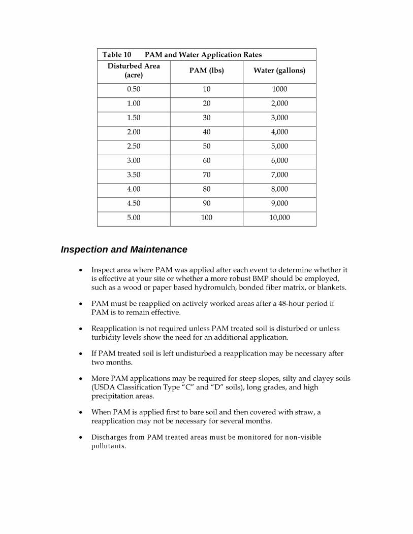
Table 10 PAM and Water Application Rates Disturbed Area
(acre) PAM (lbs) Water (gallons)
0.50 10 1000
1.00 20 2,000
1.50 30 3,000
2.00 40 4,000
2.50 50 5,000
3.00 60 6,000
3.50 70 7,000
4.00 80 8,000
4.50 90 9,000
5.00 100 10,000
Inspection and Maintenance
• Inspect area where PAM was applied after each event to determine whether it is effective at your site or whether a more robust BMP should be employed, such as a wood or paper based hydromulch, bonded fiber matrix, or blankets.
• PAM must be reapplied on actively worked areas after a 48-hour period if PAM is to remain effective.
• Reapplication is not required unless PAM treated soil is disturbed or unless turbidity levels show the need for an additional application.
• If PAM treated soil is left undisturbed a reapplication may be necessary after two months.
• More PAM applications may be required for steep slopes, silty and clayey soils (USDA Classification Type “C” and “D” soils), long grades, and high precipitation areas.
• When PAM is applied first to bare soil and then covered with straw, a reapplication may not be necessary for several months.
• Discharges from PAM treated areas must be monitored for non-visible pollutants.

Wet Season Site Stabilization (Cohesive Soils)
Description of Problem This situation occurs when an area has been disturbed and no construction activity is planned for the duration of the wet season, but these activities will be resumed after an extended period of inactivity. An example of this situation includes the construction of home pads and associated grading, but where there no home construction is planned in the near term.
Appropriate Applications There are a variety of measures that can be implemented to reduce erosion for an entire wet season. Research in Orange County has identified hydraulic wood mulch and landscape mulch as two lost cost alternatives for both flat and steeply sloped areas with cohesive soils. Wood mulching consist of applying a mixture of shredded wood mulch, bark or compost to disturbed soils. The primary function of wood mulching is to reduce erosion by protecting bare soil from rainfall impact, increasing infiltration, and reducing runoff.
Hydraulic mulch consists of applying a mixture of shredded wood fiber or a hydraulic matrix, and a stabilizing emulsion or tackifier with hydro-mulching equipment, which temporarily protects exposed soil from erosion by raindrop impact or wind. Hydraulic mulch is suitable for soil disturbed areas requiring temporary protection until permanent stabilization is established, and disturbed areas that will be re-disturbed following an extended period of inactivity.
Limitations Wood fiber hydraulic mulches are generally short lived and need 24 hours to dry before rainfall occurs to be effective. May require a second application in order to remain effective during a wetter than normal year.
Wood mulch may introduce unwanted species and is not suitable for areas exposed to concentrated flows since it will float away. In addition, it may need to be removed prior to further earthwork.
Material Selection Hydraulic matrices include a mixture of wood fiber and acrylic polymer or other tackifier as binder. Apply as a liquid slurry using a hydraulic application machine (i.e., hydro seeder) at the following minimum rates, or as specified by the manufacturer to achieve complete coverage of the target area: 2,000 to 4,000 lb/acre wood fiber mulch, and 5 to 10% (by weight) of tackifier (acrylic copolymer, guar, psyllium, etc.)
There are many types of mulches. Selection of the appropriate type of mulch should be based on the type of application, site conditions, and compatibility with planned or future uses.

Installation Hydraulic Mulches
• Prior to application, roughen embankment and fill areas by rolling with a crimping or punching type roller or by track walking. Track walking shall only be used where other methods are impractical.
• To be effective, hydraulic matrices require 24 hours to dry before rainfall occurs.
• Avoid mulch over spray onto roads, sidewalks, drainage channels, existing vegetation, etc.
• Paper based hydraulic mulches alone shall not be used for erosion control.
Wood Mulch
Prior to application, after existing vegetation has been removed, roughen embankment and fill areas by rolling with a device such as a punching type roller or by track walking. The construction application procedures for mulches vary significantly depending upon the type of mulching method specified. Two methods are highlighted here:
• Green Material: This type of mulch is produced by the recycling of vegetation trimmings such as grass, shredded shrubs, and trees. Methods of application are generally by hand although pneumatic methods are available.
- Green material can be used as a temporary ground cover with or without seeding.
- The green material should be evenly distributed on site to a depth of not more than 2 in.
• Shredded Wood: Suitable for ground cover in ornamental or revegetated plantings.
- Shredded wood/bark is conditionally suitable. See note under limitations.
- Distribute by hand or use pneumatic methods.
- Evenly distribute the mulch across the soil surface to a depth of 2 to 3 in.
• Avoid mulch placement onto roads, sidewalks, drainage channels, existing vegetation, etc.
Inspection and Maintenance
• Inspect BMPs prior to forecast rain, daily during extended rain events, after rain events, weekly during the rainy season, and at two-week intervals during the non-rainy season.

• Areas where erosion is evident shall be repaired and BMPs re-applied as soon as possible. Care should be exercised to minimize the damage to protected areas while making repairs, as any area damaged will require re-application of BMPs.
• Maintain an unbroken, temporary mulched ground cover throughout the period of construction when the soils are not being reworked.
• Regardless of the mulching technique selected, the key consideration in inspection and maintenance is that the mulch needs to last long enough to achieve erosion control objectives. If the mulch is applied as a stand alone erosion control method over disturbed areas (without seed), it should last the length of time the site will remain barren or until final re-grading and revegetation.
• Where vegetation is not the ultimate cover, such as ornamental and landscape applications of bark or wood chips, inspection and maintenance should focus on longevity and integrity of the mulch.
• Reapply mulch when bare earth becomes visible.

Wet Season Site Stabilization (Non-Cohesive Soils)
Description of Problem This situation occurs when an area with non-cohesive soils has been disturbed and no construction activity is planned for the duration of the wet season, but these activities will be resumed after an extended period of inactivity. An example of this situation includes the construction of home pads and associated grading, but where there no home construction is planned in the near term. Areas where the soils are not cohesive, such as some areas adjacent to SR 73, will need more robust measures, especially in areas with slopes greater than 5%. These measures include bonded fiber matrices, geotextiles and mats.
Appropriate Applications Bonded fiber matrix (BFM) is a hydraulically applied system of fibers and adhesives that upon drying forms an erosion resistant blanket that promotes vegetation, and prevents soil erosion. BFMs are typically applied at rates from 3,000 lb/acre to 4,000 lb/acre based on the manufacturer’s recommendation. A biodegradable BFM is composed of materials that are 100% biodegradable. The binder in the BFM should also be biodegradable and should not dissolve or disperse upon re-wetting. Typically, biodegradable BFMs should not be applied immediately before, during or immediately after rainfall if the soil is saturated. Depending on the product, BFMs typically require 12 to 24 hours to dry and become effective.
Geotextiles and mats are commonly applied on short, steep slopes where erosion hazard is high and vegetation will be slow to establish. Mattings are also used on stream banks where moving water at velocities between 3 ft/s and 6 ft/s are likely to wash out new vegetation, and in areas where the soil surface is disturbed and where existing vegetation has been removed. Matting may also be used when seeding cannot occur (e.g., late season construction and/or the arrival of an early rain season). Erosion control matting should be considered when the soils are fine grained and potentially erosive. These measures should be considered in the following situations.
• Steep slopes, generally steeper than 3:1 (H:V)
• Slopes where the erosion potential is high
• Slopes and disturbed soils where mulch must be anchored
• Disturbed areas where plants are slow to develop
• Stockpiles
• Slopes adjacent to water bodies of Environmentally Sensitive Areas (ESAs)

Limitations Bonded Fiber Matrix Bonded fiber matrixes are one of the most effective erosion control measures. The main limitation to the use of BFM is their cost, which can exceed $6,000 per acre. Geotextiles and Mats
• Properly installed mattings provide excellent erosion control but do so at relatively high cost. This high cost typically limits the use of mattings to areas of concentrated channel flow and steep slopes.
• Installation is critical and requires experienced contractors. The contractor should install the matting material in such a manner that continuous contact between the material and the soil occurs.
• Geotextiles and Mats may delay seed germination, due to reduction in soil temperature.
• Blankets and mats are generally not suitable for excessively rocky sites or areas where the final vegetation will be mowed (since staples and netting can catch in mowers).
• Blankets and mats must be removed and disposed of prior to application of permanent soil stabilization measures.
• Geotextiles and mats have maximum flow rate limitations; consult the manufacturer for proper selection.
• Not suitable for areas that have heavy foot traffic (tripping hazard) – e.g., pad areas around buildings under construction.
Material Selection Geotextiles
• Material should be a woven polypropylene fabric with minimum thickness of 0.06 in., minimum width of 12 ft and should have minimum tensile strength of 150 lbs (warp), 80 lbs (fill) in conformance with the requirements in ASTM Designation: D 4632. The permittivity of the fabric should be approximately 0.07 sec–1 in conformance with the requirements in ASTM Designation: D4491. The fabric should have an ultraviolet (UV) stability of 70 percent in conformance with the requirements in ASTM designation: D4355. Geotextile blankets must be secured in place with wire staples or sandbags and by keying into tops of slopes to prevent infiltration of surface waters under geotextile. Staples should be made of minimum 11 gauge steel wire and should be U-shaped with 8 in. legs and 2 in. crown.
• Geotextiles may be reused if they are suitable for the use intended.

Erosion Control Blankets/Mats • Biodegradable rolled erosion control products (RECPs) are typically composed of
jute fibers, curled wood fibers, straw, coconut fiber, or a combination of these materials. In order for an RECP to be considered 100% biodegradable, the netting, sewing or adhesive system that holds the biodegradable mulch fibers together must also be biodegradable.
- Jute is a natural fiber that is made into a yarn that is loosely woven into a biodegradable mesh. It is designed to be used in conjunction with vegetation and has longevity of approximately one year. The material is supplied in rolled strips, which should be secured to the soil with U-shaped staples or stakes in accordance with manufacturers’ recommendations.
- Excelsior (curled wood fiber) blanket material should consist of machine produced mats of curled wood excelsior with 80 percent of the fiber 6 in. or longer. The excelsior blanket should be of consistent thickness. The wood fiber must be evenly distributed over the entire area of the blanket. The top surface of the blanket should be covered with a photodegradable extruded plastic mesh. The blanket should be smolder resistant without the use of chemical additives and should be non-toxic and non-injurious to plant and animal life. Excelsior blankets should be furnished in rolled strips, a minimum of 48 in. wide, and should have an average weight of 0.8 lb/yd2, ±10 percent, at the time of manufacture. Excelsior blankets must be secured in place with wire staples. Staples should be made of minimum 11 gauge steel wire and should be U-shaped with 8 in. legs and 2 in. crown.
- Straw blanket should be machine produced mats of straw with a lightweight biodegradable netting top layer. The straw should be attached to the netting with biodegradable thread or glue strips. The straw blanket should be of consistent thickness. The straw should be evenly distributed over the entire area of the blanket. Straw blanket should be furnished in rolled strips a minimum of 6.5 ft wide, a minimum of 80 ft long and a minimum of 0.5 lb/yd2. Straw blankets must be secured in place with wire staples. Staples should be made of minimum 11 gauge steel wire and should be U-shaped with 8 in. legs and 2 in. crown.
- Wood fiber blanket is composed of biodegradable fiber mulch with extruded plastic netting held together with adhesives. The material is designed to enhance re-vegetation. The material is furnished in rolled strips, which must be secured to the ground with U-shaped staples or stakes in accordance with manufacturers’ recommendations.
- Coconut fiber blanket should be a machine produced mat of 100 percent coconut fiber with biodegradable netting on the top and bottom. The coconut fiber should be attached to the netting with biodegradable thread or glue strips. The coconut fiber blanket should be of consistent thickness. The coconut fiber should be evenly distributed over the entire area of the blanket. Coconut fiber blanket should be furnished in rolled strips with a minimum of 6.5 ft wide, a minimum of 80 ft. long and a minimum of 0.5 lb/yd2. Coconut fiber blankets

must be secured in place with wire staples. Staples should be made of minimum 11 gauge steel wire and should be U-shaped with 8 in. legs and 2 in. crown.
- Coconut fiber mesh is a thin permeable membrane made from coconut or corn fiber that is spun into a yarn and woven into a biodegradable mat. It is designed to be used in conjunction with vegetation and typically has longevity of several years. The material is supplied in rolled strips, which must be secured to the soil with U-shaped staples or stakes in accordance with manufacturers’ recommendations.
- Straw coconut fiber blanket should be machine produced mats of 70 percent straw and 30 percent coconut fiber with a biodegradable netting top layer and a biodegradable bottom net. The straw and coconut fiber should be attached to the netting with biodegradable thread or glue strips. The straw coconut fiber blanket should be of consistent thickness. The straw and coconut fiber should be evenly distributed over the entire area of the blanket. Straw coconut fiber blanket should be furnished in rolled strips a minimum of 6.5 ft wide, a minimum of 80 ft long and a minimum of 0.5 lb/yd2. Straw coconut fiber blankets must be secured in place with wire staples. Staples should be made of minimum 11 gauge steel wire and should be U-shaped with 8 in. legs and 2 in. crown.
Installation Bonded Fiber Matrix
• Prior to application, roughen embankment and fill areas by rolling with a crimping or punching type roller or by track walking. Track walking shall only be used where other methods are impractical.
• To be effective, hydraulic matrices require 24 hours to dry before rainfall occurs.
• Avoid mulch over spray onto roads, sidewalks, drainage channels, existing vegetation, etc.
Geotextiles and Mats Site Preparation Proper site preparation is essential to ensure complete contact of the blanket or
matting with the soil.
Grade and shape the area of installation.
Remove all rocks, clods, vegetation or other obstructions so that the installed blankets or mats will have complete, direct contact with the soil.
Prepare seedbed by loosening 2 to 3 in. of topsoil.

Seeding Seed the area before blanket installation for erosion control and revegetation. Seeding after mat installation is often specified for turf reinforcement application. When seeding prior to blanket installation, all check slots and other areas disturbed during installation must be re-seeded. Where soil filling is specified, seed the matting and the entire disturbed area after installation and prior to filling the mat with soil.
Fertilize and seed in accordance with seeding specifications or other types of landscaping plans. When using jute matting on a seeded area, apply approximately half the seed before laying the mat and the remainder after laying the mat. The protective matting can be laid over areas where grass has been planted and the seedlings have emerged. Where vines or other ground covers are to be planted, lay the protective matting first and then plant through matting according to design of planting.
Laying and Securing Matting • Before laying the matting, the friable seedbed is made free from clods, rocks, and
roots. The surface should be compacted and finished according to the requirements of the manufacturer’s recommendations.
• Mechanical or manual lay down equipment should be capable of handling full rolls of fabric and laying the fabric smoothly without wrinkles or folds. The equipment should meet the fabric manufacturer’s recommendations or equivalent standards.
Anchoring • U-shaped wire staples, metal geotextile stake pins, or triangular wooden stakes can
be used to anchor mats and blankets to the ground surface.
• Wire staples should be made of minimum 11 gauge steel wire and should be U-shaped with 8 in. legs and 2 in. crown.
• Metal stake pins should be 0.188 in. diameter steel with a 1.5 in. steel washer at the head of the pin, and 8 in. in length.
• Wire staples and metal stakes should be driven flush to the soil surface.
Installation on Slopes Installation should be in accordance with the manufacturer's recommendations. In general, these will be as follows:
• Begin at the top of the slope and anchor the blanket in a 6 in. deep by 6 in. wide trench. Backfill trench and tamp earth firmly.
• Unroll blanket down slope in the direction of water flow.
• Overlap the edges of adjacent parallel rolls 2 to 3 in. and staple every 3 ft.
• When blankets must be spliced, place blankets end over end (shingle style) with 6 in. overlap. Staple through overlapped area, approximately 12 in. apart.
• Lay blankets loosely and maintain direct contact with the soil. Do not stretch.

• Staple blankets sufficiently to anchor blanket and maintain contact with the soil. Staples should be placed down the center and staggered with the staples placed along the edges. Steep slopes, 1:1 (H:V) to 2:1 (H:V), require a minimum of 2 staples/yd2. Moderate slopes, 2:1 (H:V) to 3:1 (H:V), require a minimum of 1 ½ staples/yd2.
Inspection and Maintenance • Inspect BMPs prior to forecast rain, daily during extended rain events, after rain
events, weekly during the rainy season, and at two-week intervals during the non-rainy season.
• Inspect BMPs subject to non-stormwater discharges daily while non-stormwater discharges occur.
• Areas where erosion is evident shall be repaired and BMPs reapplied as soon as possible. Care should be exercised to minimize the damage to protected areas while making repairs, as any area damaged will require reapplication of BMPs.
• If washout or breakage occurs, re-install the material after repairing the damage to the slope.
Geotextiles and Mats
• Make sure matting is uniformly in contact with the soil.
• Check that all the lap joints are secure.
• Check that staples are flush with the ground.
• Check that disturbed areas are seeded.

Permanent Stabilization
Description of Problem This fact sheet describes measures to achieve final stabilization on a site, once land disturbing activities have been completed. This is normally achieved through establishment of vegetation on areas where bare soils are present. Many construction projects operate under the Construction General Permit, so they must achieve a vegetation coverage equal to at least 70% of the predevelopment level in order to submit a Notice of Termination.
Appropriate Applications Installation of sod is one method of final stabilization that is appropriate for disturbed areas which require immediate vegetative covers, or where sodding is preferred to other means of grass establishment. Locations particularly suited to stabilization with sod are waterways carrying intermittent flow, areas around drop inlets or in grassed swales, and residential or commercial lawns where quick use or aesthetics are factors.
The advantages of properly installed sod include:
• Immediate erosion control. • An instant green surface with no dust or mud. • Nearly year-round establishment capability. • Less chance of failure than seed. • Freedom from weeds. • Quick use of the sodded surface. • The option of buying a quality-controlled product with predictable results.
It is initially more costly to install sod than to seed. However, this cost is justified in places where sod can perform better than seed in controlling erosion. In swales and waterways where concentrated flow will occur, properly pegged sod is preferable to seed because there is no lag time between installation and the time when the channel is protected by vegetation. Drop inlets, which will be placed in grassed areas, can be kept free of sediment, and the grade immediately around the inlet can be maintained, by framing the inlet with sod strips. Sod can be laid during times of the year when seeded grass may fail, so long as there is adequate water available for irrigation in the early weeks. Ground preparation and proper maintenance are as important with sod as with seed. Sod is composed of living plants and those plants must receive adequate care in order to provide vegetative stabilization on a disturbed area.

In areas that are not landscaped, vegetation is commonly established through hydroseeding. This includes the use of a hydraulic mulch, such as a bonded fiber matrix or wood based mulch, or geotextiles on slopes greater than about 3:1 to hold the soil in place until the vegetation becomes established. Vegetation establishment occurs more rapidly when the site is irrigated.
Limitations The main limitation to the use of sod is its relatively high cost and the need for perpetual irrigation to support this type of vegetation. The main limitation to hydroseeding is the length to time necessary for vegetation establishment. In addition, hydroseeding may be used alone only when there is sufficient time in the season to ensure adequate vegetation establishment and coverage to provide adequate erosion control. Otherwise, hydroseeding must be used in conjunction with mulching (i.e., straw mulch).
Material Selection Sod Selection
• Sod should be machine cut at a uniform soil thickness of ¾ inch (± ¼ inch) at the time of cutting. This thickness should exclude shoot growth and thatch.
• Pieces of sod should be cut to the supplier’s standard width and length, with a maximum allowable deviation in any dimension of 5%. Torn or uneven pads should not be acceptable.
• Standard size sections of sod should be strong enough to support their own weight and retain their size and shape when suspended from a firm grasp on one end of the section.
• Sod should be harvested, delivered, and installed within a period of 36 hours.
Hydroseeding
The local office of the U.S.D.A. Natural Resources Conservation Service (NRCS) is an excellent source of information on appropriate seed mixes. All seeds shall be in conformance with the California State Seed Law of the Department of Agriculture. Each seed bag shall be delivered to the site sealed and clearly marked as to species, purity, percent germination, dealer's guarantee, and dates of test. The container shall be labeled to clearly reflect the amount of Pure Live Seed (PLS) contained.
Installation Sod Installation

• Prior to soil preparation, areas to be sodded should be brought to final grade in accordance with the approved plan.
• The surface should be cleared of all trash, debris and of all roots, brush, wire, grade stakes and other objects that would interfere with planting, fertilizing or maintenance operations.
• Fertilize according to soil tests. Fertilizer needs can be determined by a soil testing laboratory or regional recommendations can be made by county agricultural extension agents. Fertilizer should be worked into the soil to a depth of 3 inches with a disc, springtooth harrow or other suitable equipment. On sloping land, the final harrowing or discing operation should be on the contour.
• Sod should not be cut or laid in excessively wet or dry weather. Sod also should not be laid on soil surfaces that are frozen.
• During periods of high temperature, the soil should be lightly irrigated immediately prior to laying the sod, to cool the soil and reduce root burning and dieback.
• The first row of sod should be laid in a straight line with subsequent rows placed parallel to and butting tightly against each other. Lateral joints should be staggered to promote more uniform growth and strength. Care should be exercised to ensure that sod is not stretched or overlapped and that all joints are butted tight in order to prevent voids which would cause drying of the roots.
• On slopes 3:1 or greater, or wherever erosion may be a problem, sod should be laid with staggered joints and secured by stapling or other approved methods. Sod should be installed with the length perpendicular to the slope (on the contour).
• As sodding of clearly defined areas is completed, sod should be rolled or tamped to provide firm contact between roots and soil.
• After rolling, sod should be irrigated to a depth sufficient that the underside of the sod pad and the soil 4 inches below the sod is thoroughly wet.
• Until such time a good root system becomes developed, in the absence of adequate rainfall, watering should be performed as often as necessary to maintain moist soil to a depth of at least 4 inches.

• The first mowing should not be attempted until the sod is firmly rooted, usually 2-3 weeks. Not more than one third of the grass leaf should be removed at any one cutting.
Hydroseeding The following steps shall be followed for implementation:
• Hydroseeding can be accomplished using a multiple step or one step process. The multiple step process ensures maximum direct contact of the seeds to soil. When the one step process is used to apply the mixture of fiber, seed, etc., the seed rate shall be increased to compensate for all seeds not having direct contact with the soil.
• Prior to application, roughen the area to be seeded with the furrows trending along the contours.
• Apply a straw mulch to keep seeds in place and to moderate soil moisture and temperature until the seeds germinate and grow.
• Commercial fertilizer shall conform to the requirements of the California Food and Agricultural Code. Fertilizer shall be pelleted or granular form.
• Follow up applications shall be made as needed to cover weak spots and to maintain adequate soil protection.
• Avoid over spray onto roads, sidewalks, drainage channels, existing vegetation, etc.
• All legume seed shall be pellet inoculated. Inoculant sources shall be species specific and shall be applied at a rate of 2 lb of inoculant per 100 lb seed.
Inspection and Maintenance Sod Maintenance
• Vegetation will normally require at least weekly irrigation to become established except in the wet season.
• Sod should be inspected weekly and after each rain event to locate and repair any damage.
• Damage from storms or normal construction activities such as tire ruts or disturbance of swale stabilization should be repaired as soon as practical.