CA Datacom Best Practices Guide
55
Best Practices Guide Version 14.02 CA Datacom®
-
Upload
khangminh22 -
Category
Documents
-
view
3 -
download
0
Transcript of CA Datacom Best Practices Guide
Best Practices Guide Version 14.02
CA Datacom®

This Documentation, which includes embedded help systems and electronically distributed materials (hereinafter referred to as the “Documentation”), is for your informational purposes only and is subject to change or withdrawal by CA at any time.
This Documentation may not be copied, transferred, reproduced, disclosed, modified or duplicated, in whole or in part, without the prior written consent of CA. This Documentation is confidential and proprietary information of CA and may not be disclosed by you or used for any purpose other than as may be permitted in (i) a separate agreement between you and CA governing your use of the CA software to which the Documentation relates; or (ii) a separate confidentiality agreement between you and CA.
Notwithstanding the foregoing, if you are a licensed user of the software product(s) addressed in the Documentation, you may print or otherwise make available a reasonable number of copies of the Documentation for internal use by you and your employees in connection with that software, provided that all CA copyright notices and legends are affixed to each reproduced copy.
The right to print or otherwise make available copies of the Documentation is limited to the period during which the applicable license for such software remains in full force and effect. Should the license terminate for any reason, it is your responsibility to certify in writing to CA that all copies and partial copies of the Documentation have been returned to CA or destroyed.
TO THE EXTENT PERMITTED BY APPLICABLE LAW, CA PROVIDES THIS DOCUMENTATION “AS IS” WITHOUT WARRANTY OF ANY KIND, INCLUDING WITHOUT LIMITATION, ANY IMPLIED WARRANTIES OF MERCHANTABILITY, FITNESS FOR A PARTICULAR PURPOSE, OR NONINFRINGEMENT. IN NO EVENT WILL CA BE LIABLE TO YOU OR ANY THIRD PARTY FOR ANY LOSS OR DAMAGE, DIRECT OR INDIRECT, FROM THE USE OF THIS DOCUMENTATION, INCLUDING WITHOUT LIMITATION, LOST PROFITS, LOST INVESTMENT, BUSINESS INTERRUPTION, GOODWILL, OR LOST DATA, EVEN IF CA IS EXPRESSLY ADVISED IN ADVANCE OF THE POSSIBILITY OF SUCH LOSS OR DAMAGE.
The use of any software product referenced in the Documentation is governed by the applicable license agreement and such license agreement is not modified in any way by the terms of this notice.
The manufacturer of this Documentation is CA.
Provided with “Restricted Rights.” Use, duplication or disclosure by the United States Government is subject to the restrictions set forth in FAR Sections 12.212, 52.227-14, and 52.227-19(c)(1) - (2) and DFARS Section 252.227-7014(b)(3), as applicable, or their successors.
Copyright © 2015 CA. All rights reserved. All trademarks, trade names, service marks, and logos referenced herein belong to their respective companies.

CA Product References
This document references the following CA Technologies products:
■ CA Datacom®/DB
■ CA Datacom® Datadictionary™
■ CA Datacom® Fast Restore
■ CA Datacom® Presspack
■ CA Datacom® Server
■ CA Datacom® SQL
■ CA Dataquery™ for CA Datacom® (CA Dataquery)
■ CA ACF2™
■ CA Common Services
■ CA Explore® Performance Management for z/VSE (CA Explore PM for z/VSE)
■ CA Mainframe Software Manager™ (CA CSM)
■ CA SYSVIEW® Performance Management CA Datacom® Option (CA SYSVIEW PM CA Datacom Option)
■ CA Top Secret®
■ CA Vantage™ Storage Resource Manager (CA Vantage SRM)

Contact CA Technologies
Contact CA Support
For your convenience, CA Technologies provides one site where you can access the information that you need for your Home Office, Small Business, and Enterprise CA Technologies products. At http://ca.com/support, you can access the following resources:
■ Online and telephone contact information for technical assistance and customer services
■ Information about user communities and forums
■ Product and documentation downloads
■ CA Support policies and guidelines
■ Other helpful resources appropriate for your product
Providing Feedback About Product Documentation
If you have comments or questions about CA Technologies product documentation, you can send a message to [email protected].
To provide feedback about CA Technologies product documentation, complete our short customer survey which is available on the CA Support website at http://ca.com/docs.
Best Practices Guide Process
These best practices are based on customer experience reported through interviews with development, technical support, and technical services. Therefore, many of these best practices are a collaborative effort stemming from customer feedback.
To continue to build on this process, we encourage you to share common themes of product use that might benefit other users. Please consider sharing your best practices with us.
To share your best practices, contact us at [email protected] and preface your email subject line with "Best Practices for product name" so that we can easily identify and categorize them.
Contents 5
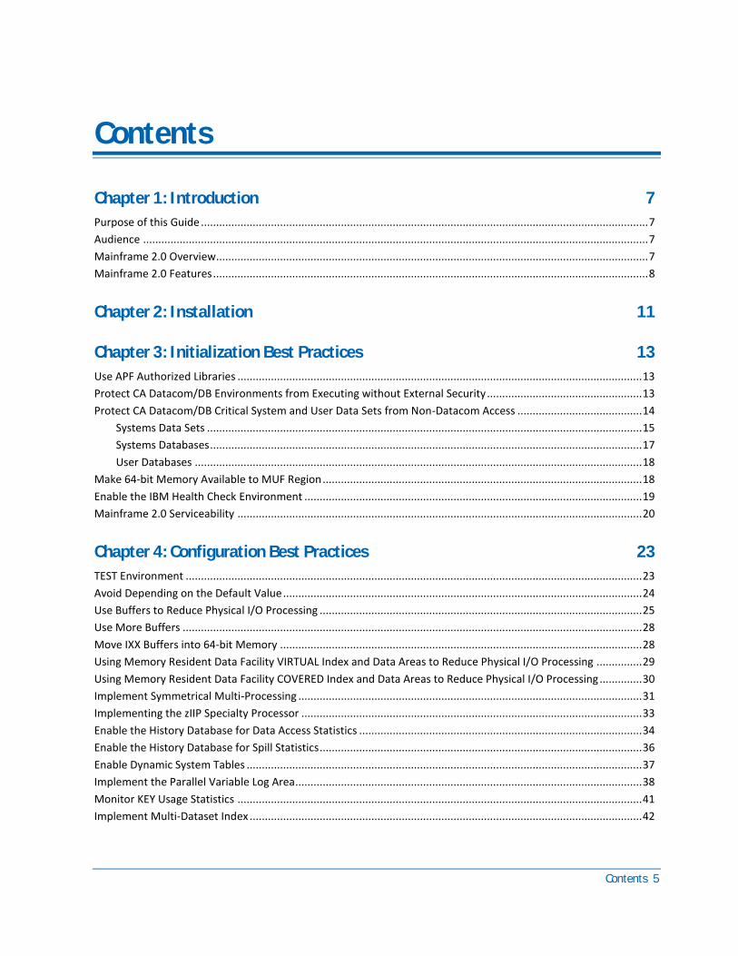
Contents
Chapter 1: Introduction 7
Purpose of this Guide ................................................................................................................................................... 7
Audience ...................................................................................................................................................................... 7
Mainframe 2.0 Overview.............................................................................................................................................. 7
Mainframe 2.0 Features ............................................................................................................................................... 8
Chapter 2: Installation 11
Chapter 3: Initialization Best Practices 13
Use APF Authorized Libraries ..................................................................................................................................... 13
Protect CA Datacom/DB Environments from Executing without External Security ................................................... 13
Protect CA Datacom/DB Critical System and User Data Sets from Non-Datacom Access ......................................... 14
Systems Data Sets ............................................................................................................................................... 15
Systems Databases .............................................................................................................................................. 17
User Databases ................................................................................................................................................... 18
Make 64-bit Memory Available to MUF Region ......................................................................................................... 18
Enable the IBM Health Check Environment ............................................................................................................... 19
Mainframe 2.0 Serviceability ..................................................................................................................................... 20
Chapter 4: Configuration Best Practices 23
TEST Environment ...................................................................................................................................................... 23
Avoid Depending on the Default Value ...................................................................................................................... 24
Use Buffers to Reduce Physical I/O Processing .......................................................................................................... 25
Use More Buffers ....................................................................................................................................................... 28
Move IXX Buffers into 64-bit Memory ....................................................................................................................... 28
Using Memory Resident Data Facility VIRTUAL Index and Data Areas to Reduce Physical I/O Processing ............... 29
Using Memory Resident Data Facility COVERED Index and Data Areas to Reduce Physical I/O Processing .............. 30
Implement Symmetrical Multi-Processing ................................................................................................................. 31
Implementing the zIIP Specialty Processor ................................................................................................................ 33
Enable the History Database for Data Access Statistics ............................................................................................. 34
Enable the History Database for Spill Statistics .......................................................................................................... 36
Enable Dynamic System Tables .................................................................................................................................. 37
Implement the Parallel Variable Log Area.................................................................................................................. 38
Monitor KEY Usage Statistics ..................................................................................................................................... 41
Implement Multi-Dataset Index ................................................................................................................................. 42
6 Best Practices Guide
Chapter 5: CA Datacom/DB DBUTLTY Configuration 45
Enlarging the DBUTLTY DBMSTLST Buffer Specifications ........................................................................................... 45
Overriding DBUTLTY DBMSTLST Buffer Specifications at Execution Time ................................................................. 46
Always Specify SORT= in DBUTLTY LOAD and RETIX Functions .................................................................................. 47
Utilize RETIX MINIMAL to Rebuild Indexes................................................................................................................. 48
Chapter 6: Simplify Mode 49
Chapter 7: CA Datacom AutoScope Toolset 51
Enable the AutoCollect Databases and Functionality for Performance Monitoring and Tuning ............................... 51
Enable the AutoStatus Database and Function for Problem Determination and Alert Processing ........................... 52
Use the AutoInfo Tool for Problem Documentation and Support Interaction ........................................................... 54
Index 55

Chapter 1: Introduction 7
Chapter 1: Introduction
This section contains the following topics:
Purpose of this Guide (see page 7) Audience (see page 7) Mainframe 2.0 Overview (see page 7) Mainframe 2.0 Features (see page 8)
Purpose of this Guide
The guide provides a brief introduction to the CA Technologies mainframe management strategy and features, and describes the best practices for installing and configuring CA Datacom.
Audience
The intended audience of this guide is systems programmers and administrators who install, configure, deploy, and maintain CA Datacom.
Mainframe 2.0 Overview
Mainframe 2.0 is our strategy for providing leadership in the mainframe operating environment. We intend to lead the mainframe marketplace for customer experience, Out-Tasking solutions, and solution innovation. After listening to customer needs and requirements to keep the mainframe operating environment viable and cost-effective, we are providing new tools to simplify usage and to energize this operating environment for years to come.
CA Mainframe Software Manager™ (CA MSM) is an important step in realizing the Mainframe 2.0 strategy. CA MSM simplifies and standardizes the delivery, installation, and maintenance of mainframe products on z/OS systems. CA MSM has a browser-based user interface (UI) with a modern look and feel for managing those solutions. As products adopt Mainframe 2.0 features and CA MSM services, you can acquire, install, and manage your software in a common way.
CA MSM provides software acquisition and installation that make it easier for you to obtain and install CA mainframe products, and apply the recommended maintenance. The services within CA MSM enable you to manage your software easily based on industry accepted best practices. The common browser-based UI makes the look and feel of the environment friendly and familiar.
Mainframe 2.0 Features
8 Best Practices Guide
We follow the IBM z/OS packaging standards using SMP/E, with some additional CA qualities of service added, to make installation simple and consistent. Additionally, through the synchronization of product releases and the use of common test environments, we will declare a yearly mainframe software stack that includes many new releases with enhanced functionality. This stack is certified for interoperability across the CA mainframe product portfolio and the base IBM z/OS product stack.
Mainframe 2.0 Features
Mainframe 2.0 has the following main features:
CA Mainframe Software Manager (CA MSM)
Delivers simplified acquisition, installation, and deployment capabilities using a common z/OS-based web application delivered through a browser-based UI. CA MSM includes the following services:
Product Acquisition Service (PAS)
Facilitates the acquisition of our mainframe products and services, including product base installation packages and program temporary fixes (PTFs). This service integrates the inventory of products available on your system with CA Support, providing a seamless environment for managing and downloading software and fixes onto your system.
Software Installation Service (SIS)
Facilitates the installation and maintenance of our mainframe products in the software inventory of the driving system. This service enables you to browse and manage the software inventory using a web interface, and automates tasks for products that use SMP/E to manage installation. You can browse downloaded software packages, and browse and manage one or more consolidated software inventories (CSIs) on the driving system.
Software Deployment Service (SDS)
Facilitates the deployment of CA Technologies mainframe products from the software inventory of the driving system. This service enables you to deploy installed products that are policy-driven with a set of appropriate transport mechanisms across a known topology. The enterprise system topology can include shared DASD environments, networked environments, and z/OS systems. Policies represent a combination of metadata input and user-supplied input. Metadata input identifies the component parts of a product. User-supplied input identifies the deployment criteria, such as where it goes and what it is named.
Electronic Software Delivery (ESD)
Enables you to get our products from an FTP server. We have improved this process so that you no longer need to build a tape to install the product.
Mainframe 2.0 Features
Chapter 1: Introduction 9
Best Practices Management
Integrates with IBM Health Checker for z/OS to verify that deployed software follows our best practices. The health checks continually monitor the system and software to provide feedback on whether the software continues to be configured optimally.
Best Practices Guide
Provides best practices for product installation and configuration.
Note: For additional information about the CA Mainframe 2.0 initiative, see http://ca.com//mainframe2.


Chapter 2: Installation 11
Chapter 2: Installation
Use CA MSM to acquire, install, and maintain CA Datacom.
Business Value
CA MSM provides a web interface, which works with ESD and standardized installation, to provide a common way to manage CA mainframe products. You can use it to download and install CA Datacom.
CA MSM lets you download product and maintenance releases over the Internet directly to your system from the CA Support Online website. After you use CA MSM to download your product or maintenance, you use the same interface to install the downloaded software packages using SMP/E.
More Information:
■ For more information about CA MSM, see the CA Mainframe Software Manager Guide.
■ For more information about product installation, see the CA Datacom Installation and Maintenance Guide.

Chapter 3: Initialization Best Practices 13
Chapter 3: Initialization Best Practices
Use APF Authorized Libraries
Previously, we recommended that you APF Authorize the CA Datacom execution (load) libraries. Authorized libraries are required for running CA Datacom Version 14.0.
Business Value
Many of the most critical CA Datacom functions require that an APF Authorized library be enabled. These functions include Data Sharing, Access Anywhere (XCF), and SRB mode (zIIP exploitation). APF Authorized libraries provide the Multi-User Facility (MUF) with the ability to manage the system functions needed to run successfully. DBUTLTY is required to run authorized but can execute some functions not being authorized. The reason this exists is because of user job streams that use JOBLIB that includes DBUTLTY executions. These need to be corrected to have STEPLIB for DBUTLTY to allow authorization.
Protect CA Datacom/DB Environments from Executing without External Security
To protect against a CA Datacom/DB environment executing without external security controls, install CA Datacom external security facilities that interface directly with CA ACF2, CA Top Secret, and IBMs RACF.
Business Value
Utilizing the external security interface greatly increases your ability to secure and protect your data. While internal product security and application security can be used, there are exposed areas that are not controlled in most cases.
Protect CA Datacom/DB Critical System and User Data Sets from Non-Datacom Access
14 Best Practices Guide
Additional Considerations
The CA Datacom/DB external security interface allows you to secure data resources according to the security ID of the user, the path the user is using (batch, CICS, CA Datacom Server, and CA Dataquery for Datacom), and the language API that is being used (RAAT, SAAT and SQL).
This security model greatly enhances the security administrator’s ability to create a security profile that matches exactly what a user needs.
In addition, the external security interface can be used to control product level functions such as CA Datacom Datadictionary administration, DBUTLTY processing, and many other product functions provided by CA Datacom.
Protect CA Datacom/DB Critical System and User Data Sets from Non-Datacom Access
Secure the CA Datacom/DB critical system and user data sets to protect against an accidental or planned intrusion. These data sets are both non-database “system” data sets and those data sets that house system and user databases. Certain system data sets can contain customer data in a readable form.
The CA Datacom/DB external security interface can protect access to the system data sets, systems database data sets, and user database data sets. It does not protect against direct data set access using tools such as IEBGENER or IEBCOPY.
Business Value
Using external security data set protection for these data sets increases your ability to secure and protect your database environment from inadvertent or planned intrusion.

Protect CA Datacom/DB Critical System and User Data Sets from Non-Datacom Access
Chapter 3: Initialization Best Practices 15
Systems Data Sets
Each system data set is commonly referred to by its z/OS DDNAME. The actual data set name is dependent on the options chosen during installation. Many data set protections are available when running with the DBSIDPR module (DBSYSID Macro) keyword SIMPLIFY MODE=YES than when it is set to NO.
The following is a list of the critical system data sets that must be protected:
CXX
Contains the definitions of all databases accessible in this CA Datacom environment.
■ Required to do any function in CA Datacom
■ Contains condensed metadata about the CA Datacom/DB databases
■ Should be externally secured
■ Must be fully accessible to the user ID used to submit the MUF startup
■ Must be fully accessible to user IDs of users who want to execute any DBUTLTY functions opening the CXX
LXX
Contains user transaction data (including data rows) used to support transaction back out and database restart (after a failure).
■ Required to start the MUF
■ Contains user data from CA Datacom/DB databases
■ Should be externally secured
■ Must be fully accessible to the user ID used to submit the MUF startup
■ Must be fully accessible to the user ID used to execute any DBUTLTY function that empties or reports on the contents of the LXX
FXX
Contains user transaction data (not including data rows) used to support fast database restart (after a failure).
■ Required to start the MUF
■ Can contain user data from CA Datacom/DB databases
■ Should be externally secured
■ Must be fully accessible to the user ID used to submit the MUF startup
■ Must be fully accessible to the user ID used to execute the DBUTLTY function that empties the contents of the FXX
Protect CA Datacom/DB Critical System and User Data Sets from Non-Datacom Access
16 Best Practices Guide
RXX
Contains user transaction data (including data rows) used to support database recovery from a backup after a data loss.
■ Typically not required to start the MUF. For more information, see LOGRCV=YES in the CA Datacom/DB Database and Systems Administration Guide.
■ Contains user data from CA Datacom/DB databases
■ Should be externally secured
■ Must be fully accessible to the user ID used to submit the MUF startup with LOGRCV=YES specified
■ Must be fully accessible to the user ID used to execute the DBUTLTY function to spill LXX records to the RXX
■ Must be read accessible to the user ID used to execute any DBUTLTY function that reports on the contents of the RXX
The external security administrator should be very careful in granting access to the LXX and RXX data sets as user data rows from any table in the environment can appear on the data set. This data set should be as secure as the highest secured table in the environment.
Access to the CXX and FXX is typically not as secure. However, any inadvertent damage to the CXX could completely shut down the CA Datacom environment.
Protect CA Datacom/DB Critical System and User Data Sets from Non-Datacom Access
Chapter 3: Initialization Best Practices 17
Systems Databases
Each system database is commonly referred to by its functional purpose and by its assigned database ID (DBID). There is one or more index areas and one or more data areas for each database. Each of these areas has one associated z/OS data set. To refer to the data sets making up the database, we typically use the z/OS DDNAME. The actual data set name is dependent on the options chosen during installation.
Critical system databases should be protected and have specific access rights, such as the following examples:
CA Datacom Datadictionary
■ Database 0002
■ Index data set, IXX002
■ Data area data set, DD1002
Contains the metadata definitions of all databases accessible in this CA Datacom environment.
■ Required to populate information into the CXX and the DDD database (see Database 0015)
■ Should be externally secured
– Must be fully accessible to the user ID used to submit the MUF startup
– Must be fully accessible to user IDs used to execute DBUTLTY functions against this database
Data Definition Directory - DDD
■ Database 0015
■ Index data set, IXX015
■ Data area data set, DDD015, MSG015, and SIT015
Contains the SQL metadata definitions of all databases that are SQL accessible in this CA Datacom environment.
■ Should be externally secured
– Must be fully accessible to the user ID used to submit the MUF startup
– Must be fully accessible to user IDs used to execute DBUTLTY functions against this database
Make 64-bit Memory Available to MUF Region
18 Best Practices Guide
User Databases
Each user database is commonly referred to by its functional purpose and by its assigned database ID (DBID). There are one or more index areas and one or more data areas for each database. Each of these areas has one associated z/OS data set. To refer to the data sets making up the database, we typically use the z/OS DDNAME. The actual data set name is dependent on the site.
For the AD site, user databases refer to the databases that have been implemented to support the CA product that is using the AD environment. The CA product documentation lists the user databases that are being installed.
User database data set protection depends on the data contents of the tables in that data set (data area) and should be externally secured as follows:
■ Must be fully accessible to the user ID used to submit the MUF startup
■ Must be fully accessible to user IDs used to execute DBUTLTY functions against this database
The user database index data sets, Index Area (IXX) and Index Area (Inn),, contain index entries that are constructed from data values on the table rows in the data areas of that database. These index entries are typically compressed and would be hard to read outside the CA Datacom environment. It is possible to decipher the index blocks in the IXX and Inn and retrieve a secured data item such as an account number.
For this reason, the IXX and Inn should be externally secured at the same level as the highest secured data table in the database as follows:
■ Must be fully accessible to the user ID used to submit the MUF startup
■ Must be fully accessible to user IDs used to execute DBUTLTY functions against this database
Make 64-bit Memory Available to MUF Region
Verify that your MUF batch job or started task allows the use of 64-bit memory.
Business Value
The 64-bit memory feature provides additional significant memory to z/OS regions making memory-resident processing much more available. Using memory-resident processing can greatly reduce physical I/O within the database region and can reduce CPU usage.
The Memory Resident Data Facility was enhanced to attempt to place VIRTUAL and COVERED areas into 64-bit memory. If the memory allocation does not fit in 64-bit memory, the MRDF allocations are placed into 31-bit data spaces.

Enable the IBM Health Check Environment
Chapter 3: Initialization Best Practices 19
MRDF COVERED data sets can significantly improve MUF request processing. For example, one user site employed MRDF COVERED processing on several high-use data sets. They were able to document a 40 percent reduction in I/O which delivered a 15 percent reduction in CPU consumption per request.
Additional Considerations
The 64-bit memory option is specified in the region parameter in your JCL. However, your site can have certain limitations on 64-bit memory set across your LPAR. Before implementing the change to add 64-bit memory, consult with your systems programming team.
Enable the IBM Health Check Environment
CA Datacom delivers IBM standard health checks for the CA Datacom environment. Each health check provides a description of the health check, any negative findings, and text that describes the mitigation plan to correct the problem.
Business Value
The CA Datacom health checks alert you to situations that can have a negative effect on the CA Datacom environment. In some cases, these effects can go unnoticed. The purpose of the health check is to alert you before damage is done and possibly avoid a CA Datacom outage.
For example, CA Datacom/DB Version 14.0 includes a health check that monitors the high-water mark of concurrent tasks in use. If the concurrent tasks in use get within a selected percentage of available tasks, you are notified. A MUF outage is required to change the number of available tasks. Health check gives you an early warning and allows you to expand the task number at the next regularly scheduled MUF cycle.
For more information, see the CA Datacom/DB Database and System Administration Guide.
Mainframe 2.0 Serviceability
20 Best Practices Guide
Mainframe 2.0 Serviceability
CA Datacom always attempts to connect to OPS/MVS when running in z/OS. It sets the STATE of a specific instance to one of four states.
■ STARTING indicates the MUF has determined it to be starting and is the only one doing so with the specific MUF name.
■ UP is the point where it starts accepting requests.
■ STOPPING indicates that an EOJ is committed.
■ DOWN occurs just before it releases its hold on the MUF name.
Note: If you are using CA Datacom/DB, the short product name for CA Datacom MUF is CADTCMDB. If you are using CA Datacom/AD, it is CADTCMAD. If you are using CA Datacom MSM, it is CADCMMSM.
Business Value
Standardizing CA product active and heartbeat events enhances Mainframe 2.0 serviceability. Approximately every 2 minutes, MUF issues an OPS/MVS heartbeat notification. A status of NORMAL and reason of blank is provided for all conditions other than the following special cases:
■ A status of PROBLEM and a reason of TERMINATION IN PROCESS if the MUF has recognized that it is failing and in the process of being terminated.
■ A status of NORMAL and a reason of EOJ REQUESTED, NOT COMMITTED if an EOJ has been requested but is not yet committed to occur. This is the time that an EOJOFF is allowed.
■ A status of NORMAL and a reason of EOJ COMMITTED if an EOJ has been requested and is now committed to occur. An EOJOFF is no longer valid.
Considerations
To fit common standards, it has no state change relating to EOJ requested but not committed. This is rare and subject to removing the EOJ. If an error is generated with the OPS/MVS communication, the following message is issued and then the error is ignored by MUF:
DB00284W - CA OPS/MVS API error return code nn, reason code nn
An OPS/MVS heartbeat message can occur such as:
OPSLOGSV CAHEARTBT DBDVM
applid:CADTCMDB
version: 14.0

Mainframe 2.0 Serviceability
Chapter 3: Initialization Best Practices 21
level:DBDVM01
status: Normal
reason:
In this message, DBDVM0 is the MUF job name, CADTCMDB is the short product name, 14.0 is the version, DBDVM01 is the MUF name, and NORMAL is the status.
For more information about messages, see the CA Datacom/DB Message Reference Guide.

Chapter 4: Configuration Best Practices 23
Chapter 4: Configuration Best Practices
Most of the CA Datacom configuration options are implemented through the Multi-User Facility (MUF) startup options. These options provide a wide variety of flexibility for each individual CA Datacom environment.
The CA Datacom/DB Database and System Administration Guide provides detailed descriptions of every startup option and each of their parameters. Study the startup options and your respective parameters.
TEST Environment
Familiarize yourself with the TEST environment as it is critical for certifying each of the MUF startup option settings before implementation in the PROD environment.
Business Value
This practice allows you to familiarize yourself with the startup options, their parameters, and their overall affect on the TEST environment before attempting the change in the PROD environment. This practice also helps to protect the PROD environment from the unexpected effects from a MUF option change and can avoid unplanned MUF outages.
Additional Considerations
While most sites have a TEST system, there can be a reluctance to set the TEST system options at the same level as the PROD environment. This is especially true for startup options controlling resource consumption (such as buffers or the Memory Resident Data Facility).
Test all significant changes in the TEST system before being applied in the PROD MUF.
Avoid Depending on the Default Value
24 Best Practices Guide
Avoid Depending on the Default Value
It is critical that you understand the default value of each option and its implications. Most options have either true defaults or implied defaults. Where possible, consider specifying all of the primary options and their parameter values to avoid relying on default values.
Business Value
Specifying each parameter provides you with two specific advantages.
■ Coding every parameter - you have taken the time to review each option and parameter selection and match it to the requirements for your site.
■ Specifying the options - you protect your site from a possible default value change in a future release.
Additional Considerations
In most cases, CA attempts to make changes to default values only with major releases of the product. The release documentation contains significant notice of any changes to default values.
There is very little difference between a true default and an implied default. Typically, a true default occurs when a startup option is specified and one or more of its parameters is left unspecified so that the system assigns a default value for that parameter.
An implied default occurs when certain startup options are not specified and the system assigns a value. The CA Datacom/DB Database and System Administration Guide presents each option and its parameters. The guide shows the default values if the option is not specified. In cases where a specific parameter is not specified, the guide may state that if this option or parameter is not specified the following action or value is assigned.
Use Buffers to Reduce Physical I/O Processing
Chapter 4: Configuration Best Practices 25
Use Buffers to Reduce Physical I/O Processing
The primary function of a CA Datacom/DB database system is to store large volumes of tables and rows while providing quick data access and update capabilities. The primary vehicle for this process is the CA Datacom MUF buffer pools. The various buffer pools in the MUF allow CA Datacom to maintain a quantity of user data and index rows in memory. These buffers hold multiple updates and provide data access for multiple MUF tasks at the same time.
Business Value
Specifying sufficient buffer pools allows CA Datacom to do memory processing which can greatly reduce physical I/O processing. Typically, physical I/O processing is considerably slower and requires more CPU usage than accessing data in memory. By specifying reasonable buffer pools, you can reduce I/O processing, improve both MUF responses, and reduce CPU consumption by the MUF. For each of the main buffer pool specifications, we provide recommendations in the following sections.
Additional Considerations
The CA Datacom/DB Database and System Administration Guide contains a chapter on optimizing CA Datacom/DB performance. This chapter discusses various techniques on how to monitor and tune the various CA Datacom buffer pools. Review this information and other resources (such as the CA Datacom webcasts) to understand how to monitor and tune buffer specifications.
CXX buffers
Used to retrieve and hold CXX database definitions and other environmental information into MUF memory. CXX buffers are also used when database definitions need to be rewritten to the CXX from MUF memory. With the introductions of optimized databases and MUF run unit assignments, the amount of CXX I/O has greatly diminished. However, the CXX buffer pool is still needed.
CXX buffers are specified in the following MUF startup option:
SYSPOOL cxxno,ixxno,dxxno,ixxbfrsize
Begin with 20 for the cxxno value. Monitor the amount of CXX I/O using the Dynamic System Tables or the PXX Summary report. If the I/O seems to be a significant amount of the total MUF I/O, you can adjust the cxxno value upward.
IXX buffers
Used to retrieve and hold Index Area (IXX) information into MUF memory. The IXX buffer pool is used to manage the high-level index information portion (IXX blocks) of the IXX data sets for all databases open in the MUF environment. IXX buffers are also used when index information needs to be rewritten to the IXX data set from MUF memory. Many factors affect the index buffers ability to keep data resident in memory. Typically the site needs enough IXX buffers to keep the active portions of the index in memory without over allocating memory for these buffers.
Use Buffers to Reduce Physical I/O Processing
26 Best Practices Guide
IXX buffers are specified in the following MUF startup option:
SYSPOOL cxxno,ixxno,dxxno,ixxbfrsize
Sites vary widely on the amount and size of the indexes in the environment. It is hard to select a value without doing an amount of performance monitoring and tuning. Begin with a value of 2000 for IXXNO. Monitor the amount of IXX I/O (using Dynamic System Tables or PXX Summary report). If the I/O seems to be a significant amount of the total MUF I/O, you can adjust the value upward as needed.
DXX buffers
Used to retrieve and hold low-level index block (DXX) information into MUF memory. The DXX buffer pool is used to manage the low-level index information portion of the IXX data sets for all databases open in the MUF environment. DXX buffers are also used when index information needs to be rewritten to the IXX data set from MUF memory. Many factors affect the index buffers ability to keep data resident in memory. Typically, you need enough DXX buffers to keep the active portions of the index in memory without over allocating memory for these buffers.
DXX buffers are specified in the following MUF startup option:
SYSPOOL cxxno,ixxno,dxxno,ixxbfrsize
Sites vary widely on the amount and size of the indexes in the environment. It is hard to select a value without doing an amount of performance monitoring and tuning. Begin with 5000 for the dxxno value. Monitor the amount of IXX I/O using the Dynamic System Tables or the PXX Summary report. If the I/O seems to be a significant amount of the total MUF I/O, you can adjust the value upward as needed.
IXX buffer size
Determines the size of each IXX and DXX buffer. For most sites, the default size of 4096 should provide a reasonable value.
If you changed the default block size of one or more of your index areas to a size larger than 4096, change this parameter value to the size of the largest index block size in use.
Using a larger buffer size increases the amount of memory used by each IXX and DXX buffer. For certain sites with large indexes (that is, a large number of key values or large key values), increasing the index buffer size may help overall index performance.
IXX buffer size is specified in the following MUF startup option:
SYSPOOL cxxno,ixxno,dxxno,ixxbfrsize
Sites can vary on the size of the indexes in the environment. It is hard to select a value without doing an amount of performance monitoring and tuning. Begin with 4096 for the ixxbfrsize value. Monitor the amount of IXX I/O using the Dynamic System Tables or the PXX Summary report. If the I/O seems to be a significant amount of the total MUF I/O, you can adjust the value upward as needed.
Use Buffers to Reduce Physical I/O Processing
Chapter 4: Configuration Best Practices 27
DATANO buffers
Used to specify the data buffer pool. The data buffer pool is the primary pool used to retrieve and hold data row information into MUF memory. The DATANO buffer pool must be specified. If the DATANO buffer pool is the only pool that is used, it needs a buffer size that is as large as the largest data area block size. The DATANO buffers manage the data block information for all data areas that have a block size that is equal or smaller than the DATANO buffer size.
Many factors affect the data buffers ability to keep data resident in memory. Typically you need enough DATANO buffers to keep a significant amount of the active portions of the data rows in memory without over allocating memory for these buffers.
DATANO size and length and the number of DATANO buffers are specified in the following MUF startup option:
DATAPOOL dataln,datano,data2ln,data2no
Sites vary widely on the amount and size of the data blocks in the environment. It is hard to select a value without doing an amount of performance monitoring and tuning. Begin with 10000 for the datano value. Monitor the amount of data I/O using the Dynamic System Tables or the PXX Summary report. If the I/O seems to be a significant amount of the total MUF I/O, you can adjust the value upward as needed.
DATA2NO buffers
Used to specify the secondary data buffer pool. The DATA2 buffer pool is the secondary pool used to retrieve and hold data row information into MUF memory. The DATA2NO buffer pool is optional. DATA2NO buffers must be larger than the DATANO buffers. If a data block size is larger than the DATANO buffer size, it is handled using the DATA2NO buffer pool. If DATA2NO is specified, it needs a buffer size that is as large as the largest data area block size. Only specify the DATA2NO buffer pool if your site has varying data block sizes and having a second data buffer pool can be used to manage the larger data block sizes.
Many factors affect the data buffers ability to keep data resident in memory. You need enough DATA2NO buffers to keep a significant amount of the active portions of the data blocks that are larger than DATANO buffer size in memory without over allocating memory for these buffers.
DATA2NO size and length and the number of DATA2NO buffers are specified in the following MUF startup option:
DATAPOOL dataln,datano,data2ln,data2no
Sites vary widely on the amount and size of the data blocks in the environment. It is hard to select a value without doing an amount of performance monitoring and tuning. Sites need to review the existing data tables and what their block sizes are. Then establish a measurement I/O for each data block size. If there is reasonable need for two data buffer pools, you can specify the optional DATA2NO buffer pool.
Use More Buffers
28 Best Practices Guide
An alternative implementation is to set the data block size for certain data sets to a large size so that they can be assigned to the DATA2NO buffer pool.
Note: The DBMSTLST module determines the size and number of index and data buffers used by the DBUTLTY program. Verify that any change to the index or data buffer sizes in the MUF is also reflected in the DBMSTLST. For more information, see the section on DBMSTLST in the DBUTLTY section of this guide.
Use More Buffers
CA Datacom Version 14.0 delivers an enhanced buffer recognition hashing algorithm. This enhanced technique significantly reduces the amount of CPU needed for managing large amounts of buffers. This improvement increases the value of having data blocks in memory as opposed to doing physical I/O.
Business Value
Specifying additional buffers does not significantly increase the CPU processing needed for managing the buffers, but having additional buffers can reduce physical I/O which also reduces CPU consumption.
Additional Considerations
The CA Datacom/DB Database and System Administration Guide contains a chapter on optimizing CA Datacom/DB performance. This chapter discusses various techniques on how to monitor and tune the various CA Datacom/DB buffer pools. Review this information and other resources (such as the CA Datacom webcasts) to understand how to monitor and tune buffer specifications.
Move IXX Buffers into 64-bit Memory
CA Datacom Version 14.0 allows the IXX buffer pool to be moved from 31-bit memory to 64-bit memory. In most z/OS sites, 31-bit memory is a limited resource while there is significant memory availability in 64 bit.
Business Value
Moving the IXX buffer pool to 64-bit memory frees up 31-bit storage that can be used to improve other MUF processes such as allocation of additional DXX and data buffers.
Using Memory Resident Data Facility VIRTUAL Index and Data Areas to Reduce Physical I/O Processing
Chapter 4: Configuration Best Practices 29
Additional Considerations
The SYSPOOL startup option at Version 12.0 has a parameter that is used to specify whether 31-bit or 64-bit memory is used to house the IXX buffers.
SYSPOOL cxxno,ixxno,dxxno,ixxbfrsize,31or64
The IXX buffer location defaults to 31-bit memory.
For sites that have 64-bit memory available, we recommend that the IXX buffers be moved to 64-bit memory:
SYSPOOL cxxno,ixxno,dxxno,ixxbfrsize,64
The CA Datacom/DB Database and System Administration Guide contains a chapter on optimizing CA Datacom/DB performance. This chapter discusses techniques on how to monitor and tune the various CA Datacom/DB buffer pools. Review this information and other resources (such as the CA Datacom webcasts) to understand how to monitor and tune buffer specifications.
Using Memory Resident Data Facility VIRTUAL Index and Data Areas to Reduce Physical I/O Processing
The primary function of a CA Datacom/DB database system is to store large volumes of tables and rows while providing quick data access and update capabilities. A unique technique for the CA Datacom site is the ability to make certain data tables completely memory-resident, using the Memory Resident Data Facility (MRDF). That is, the areas in the database are created in memory when the VIRTUAL specification is encountered. The areas in memory are created as an empty Index or data areas. All activity is processed only in memory tables, completely removing all I/O. The VIRTUAL definition can be done at MUF startup (recommended) or can be added while MUF is active for databases that are currently not open to MUF. All index or data information is lost when the MUF abends. Only use VIRTUAL specifications for index and data entries that are considered temporary in nature. These are system work data sets. Few CA Datacom/DB databases qualify for this type of processing. When specifying a database as VIRTUAL, all Index and data areas must reside in VIRTUAL storage.
Business Value
By specifying certain temporary databases as VIRTUAL, you completely remove the physical I/O for those databases. By removing the physical I/O for a database, the response time for requests in that database is improved and the overall I/O is reduced. Reductions in physical I/O can also include reductions in CPU usage.
Using Memory Resident Data Facility COVERED Index and Data Areas to Reduce Physical I/O Processing
30 Best Practices Guide
Additional Considerations
The CA Datacom system includes two system databases that are good choices for MRDF VIRTUAL databases:
■ The CBS Index database (DBID 006) contains a single Index Area that is used to house temporary indexes created to support CBS (SAAT) requests. Most clients that use the CBS Index find that adding it as a VIRTUAL database improves performance.
■ The TTM database (DBID 017) contains an Index Area and a data area used to house temporary tables created to support SQL requests. Most clients that use SQL requests that use the TTM database find that adding it as a VIRTUAL database improves performance.
Using Memory Resident Data Facility COVERED Index and Data Areas to Reduce Physical I/O Processing
The primary function of a CA Datacom/DB database system is the ability to store large volumes of tables and rows while providing quick data access and updates capabilities. A unique technique for the CA Datacom site is the ability to make certain data tables memory-resident. The area is copied into memory as the blocks are read (that is, physical I/O) for normal processing. Subsequent read processing that would typically require the area block to be reacquired by physical I/O can be copied back from the block that was stored in the COVERED memory.
Unlike VIRTUAL databases, COVERED databases use memory to save blocks and replace future physical read I/Os, but all updates to the database are still done to the Index and data areas. The memory is allocated when the COVERED specification is encountered. The area in memory is created and as blocks are accessed they are copied into the memory area. The COVERED definition can be done at MUF startup (recommended) or can be added while MUF is active for databases that are currently not open to MUF. All updates to index or data information is protected by logging and recovery.
Unlike VIRTUAL, the COVERED specification can help any data and index processing where a database has significant physical read activity. In addition, the COVERED specification can be done for the specific Index or data area, allowing you to target only the high-read physical I/O data sets.
Business Value
By specifying certain high-read databases (specifically the Index and data areas) as COVERED, you can remove significant amounts of physical read I/O for that database. By removing a significant amount of the physical I/O for the database, the response time for those database requests is improved and the overall I/O reduced. Reductions in physical I/O can also include reductions in CPU usage.
Implement Symmetrical Multi-Processing
Chapter 4: Configuration Best Practices 31
Additional Considerations
For AD sites, the CA Products that are using the AD repository can recommend that a specific index or data area be COVERED to improve processing performance.
In most sites, there are Index or data areas that have high physical read I/O content. Focus on these areas. To look for particular areas that are candidates, review the PXX summary statistics or the MUF_AREA_STATS dynamic systems table to find the areas with high-read I/O.
Implement Symmetrical Multi-Processing
The CA Datacom MUF can use multiple TCBs in parallel to do user request processing. This multiple TCB ability allows sites that have a significant MUF workload to spread that workload across multiple available processors or engines, that is, GP CPUs.
In standard SMP mode, the MUF automatically has one main task TCB where MUF internal processing occurs. This main task TCB is also used to process user requests. In addition to the main task TCB, you can specify a number of additional TCBs that can be started when needed. In this SMP environment, when additional work is available to be processed and the main task TCB is already busy with work, the additional TCB is started as needed to process the latent demand.
Business Value
The user site with heavy MUF workloads can use this feature to spread the MUF workload across multiple TCBs which are able to use multiple processors or engines to complete the workload. While this mode does not typically reduce the total GP CPU consumed, it improves the request processing elapsed time and users’ response from the MUF.
The CA Datacom SMP implementation does not allow a specific user request to use more than one TCB. By having multiple TCBs available, a poorly constructed query that is keeping a TCB busy, does not stop other better performance requests from processing on the other TCBs. This protects sites from seeing major performance degradation when these heavy queries are processing.

Implement Symmetrical Multi-Processing
32 Best Practices Guide
Additional Considerations
Sites with minimal MUF workloads, should not use SMP processing because it incurs additional overhead required for parallel task locking that is not going to be useful unless multiple task processing is occurring. Also sites having only one available processor or engine would not typically benefit from SMP processing.
SMP processing is implemented in the MUF by specifying the startup option SMPTASK.
SMPTASK maxtcb,currenttcb,readytorun
maxtcb
Sets the high-water mark for additional TCBs that can be added to do request processing.
currenttcb
Sets the current number of additional TCBs that can be added to do request processing when the amount of demand is present. The MUF adds TCBs as the workload backlog increases until it has reached the value set in currenttcb.
readytorun
Sets the amount of workload backload that is needed before an additional TCB is started. A workload backload is basically a request that is ready to run (that is, ready to be processed) that the MUF has not processed because it is busy on another request.
For example, a readytorun of 4, waits until there are four requests that are ready to run and are not currently being processed before it starts the additional TCB (TCB2). The workload backlog would have to grow to 8 readytorun requests before another TCB is started (TCB3). This continues until the number of additional TCBs equal the value set in currenttcb. Once the workload backlog drops back to zero, the additional TCBs are freed. If the workload backload redevelops again, the TCB add-on process repeats.
Console adjustments
The user can dynamically adjust the currenttcb number and the readytorun number using the MUF console commands SMPTASK and SMPTASKR.
For more information about using SMP processing, see the CA Datacom/DB Database and System Administration Guide.

Implementing the zIIP Specialty Processor
Chapter 4: Configuration Best Practices 33
Implementing the zIIP Specialty Processor
The zIIP Specialty Processor, a CPU engine, introduced by IBM for the z9 and z10 hardware systems, can be added to a hardware box without increasing the MIPS rating of that hardware operating environment. Many software license fees are based on the MIPS rating of the hardware, but the specialty processor allows you to increase the processing power of the hardware without increasing the MIPS rating and therefore without increasing the MIPS-based license fees.
Unlike its predecessors, the IFL and the zAAP processor, the zIIP processor allows certain existing z/OS workloads to be executed on the zIIP processor. For these workloads to execute on the zIIP processor, they must be executed as a Work Load Managed (WLM) Enclave SRB.
The SMP processing covered in the section titled Implement Symmetrical Multi-Processing can be changed from a main task TCB with additional TCBs for request processing to a main task TCB and WLM Enclave SRB/TCB pair for request processing. This enhancement allows portions of the existing CA Datacom workloads to be available for off-loading to available zIIP processors. The TCB of the SRB/TCB pair is used to process those parts of the workload not available for execution on the SRB.
Business Value
For sites with zIIP processors, this ability allows you to offload portions of the MUF workload to the zIIP processor which could free up the General Purpose (GP) processors for other workloads. By freeing up GP processors, you can run additional workloads or possibly delay a planned increase to the GP processor capacity.
Additional Considerations
Sites with minimal MUF workloads should not use SRB processing as it incurs additional overhead required for parallel task locking that is not going to be useful unless multiple task processing is occurring.
Sites that do not have a zIIP processor would not typically benefit from WLM Enclave SRB processing.
Enable the History Database for Data Access Statistics
34 Best Practices Guide
WLM Enclave SRB processing is implemented in the MUF by specifying the startup option SMPTASK with the additional tcborsrb parameter.
SMPTASK maxtcb,currenttcb,readytorun,tcborsrb
tcborsrb
Defaults to TCB which is the standard processing mode for r11 (and before). Changing the specification to SRB tells the MUF to convert from multiple TCB processing to the WLM Enclave SRB/TCB pair processing.
For sites that want the MUF to take advantage of zIIP processors, but want to limit the amount of the workload that is offloaded, the MUF startup option ZIIP_USER_LIMIT can be specified. Typically this limit would only be implemented for test systems where you want to use zIIP processors for some processing but also keep the test systems from putting a significant load on the zIIP processor.
For more information about using zIIP processing, see the CA Datacom/DB Database and System Administration Guide.
If you want to estimate the amount of workload that could be offloaded even though you do not have an available zIIP processor, you should implement the SMPTASK parameter with the SRB specification. Even though the SRBs are not dispatched to a zIIP processor, the MUF provides statistics on the amount of workload that would have been dispatched if the zIIP was available.
Enable the History Database for Data Access Statistics
The History Database table CADTCM_HISTORY_ADS, provides a persistent record of data area access. It provides a snapshot of logical read and physical activity read for each area that has been opened since the MUF started up. These statistics can be used to determine how much sequential access is being done per data area. By reviewing these statistics, you can analyze data access trends and determine if the data area is experiencing a decline in the ratio of logical processing requests to physical I/Os. In most cases, a non-sequential data access is not affected by the data order, and its logical requests per physical I/O ratio remains the same.
However, in some cases, sequential data access processing can be negatively affected when the data rows get out of order. Typically, such a decline in important sequential processing applications could indicate the need for a data area or database level reorganization.

Enable the History Database for Data Access Statistics
Chapter 4: Configuration Best Practices 35
Business Value
In many cases, sites run regularly scheduled data reorganizations to reorder the physical sequence of the data. For a data area or database to be physically reorganized, it must be taken offline from user access.
A site also runs these data reorganizations on a regularly scheduled basis. However, in today’s 24 hours a day, 7 days a week environment, the times that data can be offline from users is greatly diminishing.
By using the History Database table CADTCM_HISTORY_ADS, you can monitor data area processing trends and determine if and when offline data reorganization is needed.
Additional Considerations
The History Database should be defined automatically in any system that has been installed or upgraded without it. Before starting the History Database, verify that the index and data areas have been allocated, initialized and loaded null.
The MUF startup option HISTORY must be added to the MUF startup to enable the statistical collection.
HISTORY dbid
dbid
Provides the database ID for the History Database. The standard implementation uses DBID 1007 for the History Database.
The statistics are normally collected once a day at midnight (24:00:00). If you want to change the time of the once-a-day collection, you can specify the MUF startup option HISTORY_END_HOUR to change the hour of the collection.
There is no automated deletion of the statistics records collected in the CADTCM_HISTORY_ADS table. Determine when and how to remove the statistical records.
For more information about using the History Database, see the CA Datacom/DB Database and System Administration Guide.
Enable the History Database for Spill Statistics
36 Best Practices Guide
Enable the History Database for Spill Statistics
The History Database table CADTCM_HISTORY_SPL provides a persistent record of DBUTLTY SPILL executions. Detailed information is provided about each of the spills of the Log Area (LXX) to the Recovery File (RXX). This information can be used to determine the contents of each recovery file.
This information can be helpful when you find that you have a damaged database and need to recover the database from a previous backup. Once the backup is reloaded to the database, the database is at the point in time of the backup.
The spill history records help you to determine what RXX files are necessary to run a DBUTLTY forward recovery to bring the restored database forward in time.
Business Value
Typically when database damage occurs, and the user must restore a backup and do forward recovery, time-to-recover is of great importance. Unfortunately, the need to recover quickly can add additional pressure to the job of creating the recovery JCL.
If only one of the RXX files is missed or if the RXX files are specified in the wrong order, the forward recovery can fail and cause the user to restore the backup and run the recovery a second time.
By having the CADTCM_HISTORY_SPL table available, you can quickly determine all of the RXX files that have been created since the backup in question was created. Verify that these RXX files are provided in the correct sequence to the forward recovery process. This information not only speeds the job of creating the recovery JCL, but also improves the accuracy of the JCL creation.
Additional Considerations
The History Database automatically contains the additional CADTCM_HISTORY_SPL table in any system that has been installed or upgraded to the r12 level. This new table shares the same data area (A01) as the other History Database table CADTCM_HISTORY_ADS. Verify that the Index and data areas have been allocated, initialized and loaded null before starting the History Database.

Enable Dynamic System Tables
Chapter 4: Configuration Best Practices 37
The MUF startup option HISTORY must be added to the MUF startup to enable the statistical collection.
HISTORY dbid
dbid
Provides the database ID for the History Database. The standard implementation uses DBID 1007 for the History Database.
The spill statistics are created each time a DBUTLTY SPILL process is executed in a MUF environment with the LOGRCV=NO option specified.
For more information about using the History Database, see the CA Datacom/DB Database and System Administration Guide.
Enable Dynamic System Tables
The Dynamic System Tables (DST) Database is a set of virtual tables that do not reside in any permanent database. The purpose of the DST is to provide you with a unique ability to gather various system and database information dynamically from the MUF on a demand basis.
There is no cost to having the DST database available. The only CPU cost is encountered when you request information. In many cases, the cost is minimal.
Even though the information is not stored permanently, you can save the information in several ways.
DSTs also provide the interface to CA SYSVIEW PM CA Datacom Option, CA Vantage SRM, CA Explore PM for z/VSE, and several other CA products.
Business Value
The DST database is the basis for the key performance monitoring tool CA SYSVIEW PM for CA Datacom Option and the AutoScope toolset.
The DST database adds no overhead to the environment, but provides you with many significant benefits. For example, while the CXXRPT only reports information about tables row counts as of the last time it was refreshed on the CXX data set, a simple query from DSTs gives the count as of the time of the query.
Most of the information can be retrieved in programmatic fashion with simple SQL statements. The information can be easily captured for you to use into your own environment.
Implement the Parallel Variable Log Area
38 Best Practices Guide
Additional Considerations
The MUF startup option SYSTEMDBID must be added to the MUF startup to enable the DST availability.
SYSTEMDBID dbid
dbid
Provides the database ID for the DST database. We recommend that you use database ID 1000.
The DST database does not require a physical data set be allocated for its Index and data areas.
The CA Datacom/DB Database and System Administration Guide contains additional information about the using the Dynamic System Tables Database.
Implement the Parallel Variable Log Area
The Parallel Variable Log facility provides you with three key enhancements over the standard fixed block architecture LXX.
For sites where the LXX data set is DASD replicated (that is, mirrored) across long distances, the replication software has had some difficulties when replicating the fixed block LXX. The problem stems around the CA Datacom requirement to rewrite the current log block every time a COMMIT is issued. With today’s systems using the large block sizes for the LXX (1/2 or 1/3 track), the number of times and the frequency a specific physical log block can be rewritten in the process of verifying the commit point can be significant. The high frequency rewrites of the same physical block can cause some significant delay in the replication process. With the parallel variable log, you can set the LXX block size to be variable, 4 K to 32 K. This allows the system to create more and smaller physical blocks on the LXX data set. Having more and smaller blocks reduces the number of rewrites that occur and removes some of the delay experienced by the replication process.
The second benefit of the parallel variable log is the ability to specify multiple buffers to hold active log processing. In a system using fixed block logging, there is a single log buffer that is created to match the size of the physical data block on the LXX. When the log buffer fills and the next log record will not fit in the current buffer, the log buffer is written to the matching log block one last time. After the I/O completes, the log buffer is emptied and processing continues. During this process, any update activity in the system must wait because its matching log record cannot be placed into the single log buffer. This created a brief pause in all update processing.
Implement the Parallel Variable Log Area
Chapter 4: Configuration Best Practices 39
For sites implementing the parallel variable log, there is an ability to specify multiple log buffers, the default is 8. Since multiple buffers are available, there is an ability to asynchronously I/O a full buffer while allowing update processing to continue by writing their log records into the next available log buffer. Only when all log buffers are full and awaiting an I/O would a pause occur (that is, similar to the fixed block full buffer pause). Because you can specify additional log buffers (up to 99), you can almost completely eliminate the pauses.
The final benefit is the combination of the multiple log buffers and the CA Datacom ability to do multiple block I/Os. For years, CA Datacom has done multi-block I/Os when processing data buffers to and from the data areas. With the parallel variable log, this same technique has been introduced allowing a single I/O to write multiple log buffers in sequence to their respective physical DASD blocks, which greatly reduces the number of physical I/Os necessary to process the log buffers to DASD.
Regardless of which method of logging is used, either fixed block or variable block, the DBUTLTY SPILL process and all downstream processing of the RXX data sets remains the same. There should be no user processing affected by the change in log processing.
Business Value
Any site implementing DASD replication (that is, mirroring) will find that a LXX data set on a busy CA Datacom system will be using a significant amount of the replication resources. In many cases, the systems overall response time will be based on how fast the replication processing can handle the LXX data set. For these sites, the parallel variable log will provide significant relief.
If you do not have DASD replication processing, you will find that the parallel variable log with a maximum block size can greatly reduce the amount of LXX I/Os which saves CPU usage, and you will also find that maintenance requests (that is, the adds, updates, deletes) will have a faster elapsed processing time due to the removal of the log buffer full “pauses”.
It has been shown that any site with significant CA Datacom processing will benefit from using the parallel variable log.
Additional Considerations
The specification on which type of log processing is used is decided when the LXX data set is initialized using the DBUTLTY INIT AREA=LXX function.
Implement the Parallel Variable Log Area
40 Best Practices Guide
The MUF must be down to initialize the LXX data set and any data left on the LXX will be lost. You must take care to:
1. Stop all processing in the MUF.
■ COMM CLOSE all DBIDs
■ ACCESS OFF all DBIDs
2. Spill the contents of the LXX to the RXX.
■ Verify that the date/time in the console message of the last LXX record spilled to the RXX corresponds with the time of the process beginning.
■ If the date/time is from an earlier time, research if this is correct. Verify that the databases are all closed and access is set to off.
3. Shut down the MUF.
4. Run the DBUTLTY INIT AREA=LXX function:
DBUTLTY INIT AREA=LXX,BLKSIZE=32760,VARIABLE=YES
The BLKSIZE must be set to 32760 when VARIABLE is set to YES.
The number of MUF log buffers created for the parallel variable log system defaults to 8. To increase or decrease the amount of parallel log buffers, you can specify the X_LOG_AHEAD_BLKS MUF startup option. The maximum value is 99. You can determine the number of MUF log buffers that have been in use for a given MUF execution by querying the Dynamic System Table MUF_LOGGING or by reviewing the MUF EOJ report.
For sites that are using DASD replication, the MUF startup option X_LOG_MINIMUM_BLK can be used to set the minimum variable block size used to create a LXX physical block. Specifying a small number allows MUF to create many small LXX blocks and greatly diminishes the amount of physical block rewrites. However, using a small value would also significantly reduce DASD utilization due to the overhead of having many small blocks versus a couple of large blocks. For sites not doing DASD replication, this value should be left at the maximum of 32760.
More Information
■ For more information about using the DBUTLTY to initialize the LXX, see the CA Datacom/DB DBUTLTY Reference Guide.
■ For more information about using the parallel variable log file, see the CA Datacom/DB Database and System Administration Guide.
Monitor KEY Usage Statistics
Chapter 4: Configuration Best Practices 41
Monitor KEY Usage Statistics
The CA Datacom system allows multiple indexes or keys to be created for each CA Datacom table. Keys are added to the table’s definitions to improve data access capabilities.
Each key on a given table has three specific costs:
■ Each add or delete of a row, requires that all keys on the table must be added or deleted for the matching row. In addition, an update request against a specific row can cause key values to be updated if a data column or columns used to build the key have been changed.
■ For each key and its unique key-values, there is a storage requirement in the IXX data set.
■ There is a more subjective cost of having many keys in a given IXX data set that is based on the number of binary levels that is required to house all of the key values for a given database. Each key that is defined, adds to the amount of index blocks that must be maintained. These index blocks are part of CA Datacom binary b-tree+ index structure. The more index blocks you have, the more likely that you have a multiple level index tree structure. The more levels in the index, the more logical processing that every indexed process (for the entire database) must take to find the requested data row.
The Dynamic System Table DIR_KEY provides a count of accesses by RAAT (USES_RAAT), SAAT (USES_SAAT) and SQL (USES_SQL). These counts show key usage since the last time the IXX was rebuilt.
You can monitor these key usage statistics and determine if specific keys exist that no longer are being used. Consider removing these keys.
In addition, you can review keys that have limited or light use. You can determine which programs are using these keys and, if possible, change the program to other keys on the table and remove the lightly used keys.
Business Value
Reducing the number of unused keys (per table) reduces the processing (CPU usage and I/O) needed to add or delete rows and saves IXX data set space. In addition, reducing the number of keys in the IXX can have a positive effect on the index processing levels.

Implement Multi-Dataset Index
42 Best Practices Guide
Additional Considerations
For a lightly used key, you can set up the CA Datacom/DB Accounting Facility to collect the names of the programs or transaction that are using the key. This could aid in determining if the lightly used key could be removed and the programs changed to another existing key.
For more information about using the Dynamic System Tables database, see the CA Datacom/DB Dynamic System Tables Reference Guide.
Implement Multi-Dataset Index
This best practice is associated with two of the preceding best practices.
In the previous section on using MRDF COVERED Index and data areas to reduce physical I/O processing, we discussed the use of MRDF COVERED data sets to keep Index Areas memory-resident to improve performance and reduce physical I/O. One of the constraints on MRDF processing is the limit of 9 GB of 64-bit memory per Index Area (or 2 GB, if using 31-bit memory). Many of the largest database Index Areas may exceed the 9 GB limit. In these cases, you can choose to cover part of the IXX to gain performance. However, there is no way to tell MRDF to only cover the high-use keys.
In the previous section on monitoring KEY usage statistics, we described methods that you can use to monitor which keys are heavily used and which keys are lightly used.
The Multi-Dataset Index allows you to spread the database index across multiple data sets. The database must still have an IXX data set which houses all CA Datacom internal index entries, such as the free space index, URI index, and the default storage location for all user-specified table indexes (keys).
In addition to the IXX, you can specify additional Inn data sets, where the nn is a number between 01 and 99. The Inn data sets are initialized like the IXX and can be selectively used to house user-specified keys.
Three specific user benefits are provided:
■ It allows large index areas to be spread across multiple data sets. Because there are multiple data sets, each data set has a subset of the index blocks that were housed in the global IXX. The internal binary b-tree+ structures have fewer blocks to manage, and therefore can have fewer levels and be more efficient to process.
■ Since you can selectively move only certain indexes (keys) to one of these new data sets, you can separate heavy use indexes from lightly used indexes for performance reasons.
Implement Multi-Dataset Index
Chapter 4: Configuration Best Practices 43
■ Since there are multiple data sets, any failure on a given data set can be recovered by running an index rebuild on only the failed data set’s key IDs. More information is provided in the sections describing the DBUTLTY RETIX function.
Once you use the key usage statistics to determine what keys can be moved to the additional Inn data sets, monitor the multiple index data sets to determine which of the data sets have the heaviest read I/O activity. Since the Inn data sets most likely are smaller in size, it makes it easier for you to employ the MRDF COVERED option on the high-use index data sets and get an overall better return for the memory allocated.
Business Value
The multiple data sets can be used to segment large index data sets by key ID. This segmentation provides three significant advantages:
■ Since there are multiple data sets, and a data set that is lost or damaged can be recreated separately, the database outage is greatly reduced.
■ Multiple data sets have smaller subsets of blocks which should provide an improved efficiency of processing.
■ By separating high-use keys to their own data sets, the CA Datacom MRDF processing is used to significantly improve the processing for those high-use keys.
Additional Considerations
To implement a Multi-Data Set Index, use the CA Datacom Datadictionary to change the definitions for the selected keys to select your alternate Inn data set. When you are finished, catalog the database definition to the CXX. The CXX definition shows the new alternate Inn area or areas. Allocate the Inn data set and then run a DBUTLTY INIT AREA=Inn function. Once these additional areas are created and initialized, reload the database table or recreate the index areas using DBUTLTY RETIX.
A given key ID can only be directed to the IXX or to an Inn data set.
More Information
■ For more information about the DBUTLTY INIT and RETIX functions, see the CA Datacom/DB DBUTLTY Guide.
■ For more information about making theCA Datacom Datadictionary changes to the key definitions, see the CA Datacom Datadictionary guides

Chapter 5: CA Datacom/DB DBUTLTY Configuration 45
Chapter 5: CA Datacom/DB DBUTLTY Configuration
The CA Datacom/DB DBUTLTY program provides the majority of database utility functions for the CA Datacom environment. Over 30 different database utility functions can be executed using the DBUTLTY program.
Enlarging the DBUTLTY DBMSTLST Buffer Specifications
During installation of CA Datacom, a default DBMSTLST module is assembled. This default assemble determines the various buffers that are allocated for use when running DBUTLTY. For many of the important database functions performed by DBUTLTY, the buffers specified by DBMSTLST determine the performance metrics of the DBUTLTY execution, such as, elapsed time, I/Os, and CPU usage.
The default buffer allocations for DBMSTLST are quite small to keep the amount of 31-bit space that is necessary to execute the DBUTLTY program at a minimum. However, in most sites today, there is adequate 31-bit memory available and, using these small default allocations is wasting resources and slowing performance of the DBUTLTY functions.
The following are the default buffer allocations for DBMSTLST:
CXXNO=10
DATANO=15
DXXNO=16
IXXNO=8
During various testing, we have determined that different DBUTLTY functions perform better with additional buffers specifications. You can experiment with having different copies of the DBMSTLST module stored in different user libraries. Then, at DBUTLTY execution time, use the library with the DBMSTLST that performs best for that utility function.
For most sites, the multiple DBMSTLST module approach is too complicated and time consuming. While the amount of buffers needed by each DBUTLTY function varies, consider the following as a minimal number of buffers in DBTMLST :
CXXNO=10
DATANO=128
DXXNO=64
IXXNO=32

Overriding DBUTLTY DBMSTLST Buffer Specifications at Execution Time
46 Best Practices Guide
For sites with available space, some additional performance can be gained with the following slightly higher buffers numbers:
CXXNO=10
DATANO=256
DXXNO=512
IXXNO=256
After a new installation process, immediately rerun the install job that builds the DBMSTLST module and specify the expanded buffer setting you select.
Business Value
Having the additional buffer sizes when not needed does not slow the processing of the utility. However, having the additional buffers for the functions that need them could greatly improve processing time and resource consumption for DBUTLTY.
Additional Considerations
Certain DBUTLTY functions, such as BACKUP, EXTRACT, and REORG, allow the specification of the SEQBUFS= in the DBUTLTY control cards. For these utility functions, specifying a value for SEQBUFS overrides the number of buffers specified in the DBMSTLST DATANO parameter. In z/OS sites, if the SEQBUFS is not specified, the value is set to 128. The BACKUP, EXTRACT, and REORG functions are guaranteed to have at least 128 data buffers for their processing.
Overriding DBUTLTY DBMSTLST Buffer Specifications at Execution Time
As discussed in the previous section, the default DBUTLTY DBMSTLST module does not specify enough buffers for large DBUTLTY executions. The previous section provided recommendations for changes to the DBMSTLST settings to provide a more substantial set of buffers.
However, this approach lacks some flexibility for certain utility operations where more buffers could aid in speeding up the processing. For example, during a DBUTLTY RECOVERY=FORWARD operation having a much larger number of IXX, DXX, and data buffers could significantly improve the recovery time and shorten the time it takes to rebuild a database after a failure. However, for other utilities such as a normal backup or extract, these additional buffers may not be beneficial.
For these special cases, the DBUTLTY SET command can be used to override the buffer settings for a given DBUTLTY execution. Once the SET command has been issued, the selected buffer allocation remains in effect until the DBUTLTY execution ends or another SET command is encountered.
Always Specify SORT= in DBUTLTY LOAD and RETIX Functions
Chapter 5: CA Datacom/DB DBUTLTY Configuration 47
Business Value
Using the SET command can allow you to experiment with the number of buffers needed to support long-running DBUTLTY jobs. In some cases, the ability to add additional buffers to speed recovery or other processing can be critical to sites that have experienced a database outage.
Additional Considerations
The DBUTLTY SET function uses a freeform text processor to pass various commands and settings from the JCL stream to the DBUTLTY program. Providing buffer specifications is just one of the overrides that this function can provide to the DBUTLTY program, as shown in the following example:
SET OPTION1=’DATANO=9999;DXXNO=9999;IXXNO=999’
The SET function shows you how to override data buffers to 9999, DXX buffers to 9999 and IXX buffers to 999.
Do not to set the buffers numbers so high that the DBUTLTY 31-bit memory size exceeds the size of the region’s available 31-bit memory. For DBUTLTY functions that also include a sort, some planning must be done to help ensure ample room for the sort’s 31-bit memory requirements.
Always Specify SORT= in DBUTLTY LOAD and RETIX Functions
Many DBUTLTY functions, such as RETIX at the database level, require the SORT option to be specified. However, there are many older area level LOAD or RETIX jobs that are still running at user sites that do not have the SORT= parameter specified.
Running the functions without the SORT option can greatly reduce the performance of the utility and in some cases can create index areas that are not as efficient as they could be.
Business Value
Using the SORT= parameter on LOAD and RETIX functions improves the performance of the job execution and provides the most efficient Index Area possible.
Additional Considerations
SORT=0 is the same as not specifying the SORT parameter. Specify a sort value that is near the amount of key values (that is, keys per table times rows per table) that are processed.
If you do not know the amount of key-values specify a reasonably high number such as 999999 for small to medium tables and 999999999 for large tables.

Utilize RETIX MINIMAL to Rebuild Indexes
48 Best Practices Guide
Utilize RETIX MINIMAL to Rebuild Indexes
The DBUTLTY RETIX function is used to rebuild a disabled, that is, not loaded, or damaged Index Area. This process accesses the data rows and rebuilds each of the index entries.
Typically, index entries become disabled when the database description has been changed and a change to the keys definition, the columns (fields), was made.
Rebuilding the Index Area is typically faster than reloading the data, which includes rebuilding the Index Area. For large database indexes, this could still be a significant time consuming effort.
The CA Datacom/DB has been updated to track what key IDs in the index are disabled, not loaded, or are invalid for some reason. You can now run the DBUTLTY RETIX function with the MINIMAL=YES parameter. This tells the DBUTLTY to only rebuild the invalid index entries.
Business Value
Using the RETIX with MINIMAL=YES can significant reduce the time it takes to rebuild a damaged or invalid index and greatly reduces the time it takes to get a database back online.
Additional Considerations
With multiple data set indexes, the RETIX function needs to be executed against each of the IXX and Inn data sets that have a disabled key ID. RETIX MINIMAL=YES is valid for multiple data set indexes.

Chapter 6: Simplify Mode 49
Chapter 6: Simplify Mode
Utilize RETIX MINIMAL to Rebuild Indexes
50 Best Practices Guide
The purpose of the DBSYSID Macro parameter SIMPLIFY_MODE=YES is to specify the use of Simplify mode. Simplify mode makes using CA Datacom easier and frees Database Administrator (DBA) resources for other matters, particularly in special situations. Simplify mode protects data sets by making it harder for users to accidentally overlay important information, a situation that would require substantial Database Administrator effort to correct. Therefore, we recommend that if possible you use CA Datacom/DB in the Simplify mode. Depending on your environments, there should be no (or only minimal) problems using the Simplify mode. It is possible that some of the rules and requirements associated with using the Simplify mode could require some effort to set up. Some effort could be required to learn how to use Simplify mode, and some elements of the environment could require changes. That is why Simplify is an option instead of a requirement.
Note: Simplify mode is required for CA Datacom/AD but optional, though recommended, for CA Datacom/DB.
Business Value
A DBA’s time is becoming more valuable as time goes on. Handling special cases can be time consuming. Using the Simplify mode assumes a DBA has the time required to learn and use this new option. The process takes less time for an experienced DBA than for a new one. Because a new DBA has no history or knowledge of what is needed, there is also the possibility that while learning, they could make the problem worse before getting the help needed to correct any errors that were unintentionally made.
The Simplify Mode would prevent the lack of 24x7 MUF availability due to some of the following user errors.
CXX overlay
■ Initializing a CXX while MUF is enabled or a LOAD of a CXX backup
■ DBUTLTY executing, such as loading a user database that requires many hours and is incomplete
■ Accidentally using the CXX as the output of a DBUTLTY function, such as BACKUP AREA=DD1,DBID=2,DDNAME=CXX or AUTOINFO DDNAME=CXX
■ RESET of the CXX and allowing parallel execution of DBUTLTY functions that are in conflict
LXX overlay
■ Initializing a LXX while MUF is enabled
■ Accidentally using the same LXX for different multiple MUF executions
Index or data area overlay
■ Using a test CXX environment but pointing to production data sets and overlaying production
Chapter 7: CA Datacom AutoScope Toolset 51
Chapter 7: CA Datacom AutoScope Toolset
In AutoScope, we have delivered a new set of tools for the Database Administrator. These tools provide a wide variety of functionality to assist the DBA in managing the CA Datacom environment.
The AutoInfo tool has been designed to assist the AD user in collecting and documenting information about the site's AD repository and its current configuration.
Enable the AutoCollect Databases and Functionality for Performance Monitoring and Tuning
The AutoCollect databases provide a persistent repository for various environmental and statistical information extracted from the MUF Dynamic System Tables.
In addition to providing a repository for the DST information, the AutoCollect functions provide simple ways to create performance measurements and resource utilization based on pre-determined time schedules. Using AutoCollect, you can capture usage information based on processing schedules such as prime shift, overnight, and weekends.
In addition to collecting the statistics and calculating the usage amounts (known as the Deltas), the AutoCollect tool automatically calculates various business value measurements such as database request process per CPU second, database requests per elapsed second, and database requests per physical I/O. With the business value measurements, AutoCollect also generates a business value details table that has a large number of common SYSPROG ratios used to measure the CA Datacom environment.
The overhead to collect the information is minimal. The work to process the statistics in usable Deltas and present the information has a relatively small resource footprint. The management process can also be offloaded to a non production MUF for processing to remove any load from the production systems.
Enable the AutoStatus Database and Function for Problem Determination and Alert Processing
52 Best Practices Guide
While most users have a variety of home grown tools to measure performance, the AutoCollect system provides a standard implementation that every z/OS CA Datacom site can use.
Business Value
AutoCollect provides a straightforward simple process to collect statistics and generate performance metrics that can be compared from one MUF to another or even one site to another.
AutoCollect measurements can be used to locate opportunities for tuning to produce improved performance, as well as provide the means to verify the effect of any change. This includes not just tuning changes, but also changes such as new software in the operating system, CICS, CA Datacom releases, and more, and new hardware such as CPU, DASD, and memory. You can also use it to track processing growth due to increased transactions, as well as processing growth due to application changes.
Additional Considerations
For the AutoCollect function to work, you must have the Dynamic System Tables Database enabled.
All of the AutoCollect processes are executed using the CA Datacom/DB DBUTLTY AUTOCOLL function. For more information on this function, see the CA Datacom/DB DBUTLTY Guide.
For detailed implementation and usage information as well as recommended implementation scenarios, see the newly created CA Datacom/DB AutoScope User Guide.
Enable the AutoStatus Database and Function for Problem Determination and Alert Processing
The AutoStatus Database provides a persistent repository for active task information extracted from the MUF Dynamic System Tables Database.
In addition to providing a repository for the task information, the AutoStatus function provides a simple way to iteratively collect the active task information for one or more MUFs on the same LPAR. The information can be collated by collection timestamp allowing you to see all MUF activity on a given LPAR in one place.
This information can be used for debugging problems that occurred in the past, such as a user calls in that processing was slow this morning around 8 a.m. but seems okay now. Can you tell what was happening this morning?
Enable the AutoStatus Database and Function for Problem Determination and Alert Processing
Chapter 7: CA Datacom AutoScope Toolset 53
In addition, you can write your own post processors to review the AutoStatus snapshots, detect if there are any response issues, and, if detected, generate automated alerts. For example, a site using AutoStatus never noticed that at certain times CICS transactions would hang for a minute or two and then resume. Users noticed the problem, but never complained. Their AutoStatus alert system caught the fact that periodically batch jobs would run that locked data rows for a few minutes. Each time they ran, they held records needed by CICS transactions, which caused the CICS transactions to wait for exclusive control. Once the batch jobs were detected, a small program fix was done and the CICS delays disappeared.
The task status information can be used to look for many different conditions that could be affecting MUF performance.
The overhead to collect the information is minimal. The work to process the task activity statistics has a relatively small resource footprint. In addition, the management process can be offloaded to a non-production MUF for processing to remove any load from the production systems.
While most users have a variety of home grown tools to measure performance, the AutoStatus system provides a standard implementation that every z/OS Datacom site can use.
Business Value
AutoStatus provides a straightforward simple process to collect active task statistics from all MUFs on an LPAR and store them as a one point in time snapshot. This information can be used to do after the fact problem analysis and well as interactive alert processing.
Using this functionality can improve the DBAs control of a given system without increasing their workload.
Additional Considerations
For the AutoStatus function to work, you must have the Dynamic System Tables Database enabled.
The AutoStatus function is executed using the CA Datacom/DB DBUTLTY AUTOSTAT function. For more information about this function, see the CA Datacom/DB DBUTLTY Guide.
For detailed implementation, usage information, and recommended implementation scenarios, see the newly created CA Datacom/DB AutoScope User Guide.
Use the AutoInfo Tool for Problem Documentation and Support Interaction
54 Best Practices Guide
Use the AutoInfo Tool for Problem Documentation and Support Interaction
The AutoInfo function provides a simple way for you to collect all of the environmental information for a selected MUF in one simple report.
In addition to providing a report for the user, AutoInfo can also create a simple sequential data set that can be transported to CA Support. Upon reception, CA Support can convert the sequential data set into a working spreadsheet that provides the Support technician with the MUF environmental information.
AutoInfo can be used to reduce the amount of work a DBA must go through to document a given MUF environment. This is useful when working with a CA Support technician on a CA Datacom issue. It is also useful as a documentation tool, where you can save environmental information for a set of MUFs in case later research is needed.
Business Value
AutoInfo provides a simple process to quickly collect MUF environmental information reducing the amount of time needed to document a support issue.
Using this functionality, you can improve the DBAs control of a given system and help to reduce their workload.
Additional Considerations
For the AutoInfo process to provide the maximum amount of information, you must have the Dynamic System Tables Database enabled.
The AutoInfo function is executed using the CA Datacom/DB DBUTLTY AUTOINFO function. For more information about this function, see the CA Datacom/DB DBUTLTY Guide.
For detailed implementation, usage information, and recommended implementation scenarios, see the newly created CA Datacom/DB AutoScope User Guide.
Index 55
Index
A
audience for this guide • 7 AutoScope toolset • 51
B
buffer pools • 25
C
certifying MUF settings with TEST • 23 configuring CA Datacom options • 23 COVERED index • 30
D
DBUTLTY RETIX • 48 DEFAULT usage • 24
F
features of Mainframe 2.0 best practices management • 8 ESD • 8 MSM • 8 PAS • 8 SAS • 8
K
KEY usage statistics • 41
L
Log Area history • 36
M
Mainframe 2.0 defined • 7 memory availability • 18 memory for MUF regions • 18 MF 2.0 • 7 monitoring KEY usage statistics • 41 MRDF • 29, 30 Multi-Dataset Index • 42
O
overview of Mainframe 2.0 • 7
P
parallel TCBs • 31 problem and alert processing • 52 protecting critical system and user data sets • 14 protecting user database data sets • 18
R
rebuild indexes with RETIX • 48 recovery file history • 36 reducing I/O processing • 25 RETIX MINIMAL • 48 running the SORT option • 47
S
securing CA Datacom/DB access • 13 securing Index areas • 18 Simplify mode • 49 SORT= • 47 Spill statistics • 36 strategy for Mainframe 2.0 • 7 symmetrical multi-processing • 31
T
TEST • 23
U
understanding DEFAULT values • 24
V
VIRTUAL index • 29