lateral-torsional buckling of beams elastically restrained ...
Upload
khangminh22Category
view
0download
0
Missouri University of Science and Technology Missouri University of Science and Technology
Scholars' Mine Scholars' Mine
International Specialty Conference on Cold-Formed Steel Structures
(2006) - 18th International Specialty Conference on Cold-Formed Steel Structures
Oct 26th, 12:00 AM
Distortional Buckling of Simple Lipped Channel in Bending Distortional Buckling of Simple Lipped Channel in Bending
Carlos Eduardo Javaroni
Roberto Martins Goncalves
Follow this and additional works at: https://scholarsmine.mst.edu/isccss
Part of the Structural Engineering Commons
Recommended Citation Recommended Citation Javaroni, Carlos Eduardo and Goncalves, Roberto Martins, "Distortional Buckling of Simple Lipped Channel in Bending" (2006). International Specialty Conference on Cold-Formed Steel Structures. 1. https://scholarsmine.mst.edu/isccss/18iccfss/18iccfss-session2/1
This Article - Conference proceedings is brought to you for free and open access by Scholars' Mine. It has been accepted for inclusion in International Specialty Conference on Cold-Formed Steel Structures by an authorized administrator of Scholars' Mine. This work is protected by U. S. Copyright Law. Unauthorized use including reproduction for redistribution requires the permission of the copyright holder. For more information, please contact [email protected].
brought to you by COREView metadata, citation and similar papers at core.ac.uk
provided by Missouri University of Science and Technology (Missouri S&T): Scholars' Mine
133
Eighteenth International Specialty Conference on Cold-Formed Steel Structures Orlando, Florida, U.S.A, October 26 & 27, 2006
Distortional Buckling of Simple Lipped Channel in Bending – Results of the Experimental Analysis versus Direct Strength
Methods
Carlos Eduardo Javaroni1 and Roberto Martins Gonçalves2 Abstract Cold-formed steel members are subject to failure caused by buckling, normally under loads smaller than those corresponding to partial or total yielding of the cross section. The buckling of members in bending can be classified as local or global, and the occurrence of one or the other type is expected by the members’ geometric characteristics and by the constraints and load conditions. One of the local instability modes that can characterize a member’s failure is distortional buckling of the cross section occurring on its own plane and involving lateral displacements and rotations. This paper presents and discusses the procedures and results obtained from experimental tests of cold-formed steel members under bending. Forty-eight beams were carried out on members in simple lipped channel, in pairs, with 6-meter spans and loads applied by concentrated forces at every 1/3 of the span. The thickness, width and dimensions of the stiffeners were chosen so that the instability by distortion buckling of the cross section was the principal failure mode expected. The experimental results are compared with the obtained results by using the direct strength method.
1 Doctor of Science, Professor at the Civil Engineering Department - UNESP, Bauru campus. E-mail: [email protected] 2 Associate Professor, Structure Department, Engineering School of São Carlos, University of São Paulo. E-mail: [email protected]
134
Introduction Significant advances have been achieved in cold-formed steel member applications in steel structures in Brazil, allied with intensified research all over the country. The combined efforts from the country’s steel mills and from educational and research institutions have contributed immeasurably to these advances. Design procedures for the problem of structural member instability have become more complex. From this standpoint, steel members can be subject to one of two kinds of instability: local buckling or global buckling. Global buckling occurs in the members and classic examples of this phenomenon are Euler’s buckling of columns and lateral torsional buckling of beams. The failure mode of local buckling occurs in the individual plate elements of the cross section, usually involving bars with a relatively small slenderness. This type of failure may be characterized by local or by distortional buckling. Local buckling occurs in the member’s plate component element with displacements from the normal direction of its plane. The critical load for this element can be determined by the effective width concept. Distortional buckling is characterized by distortion of the bar’s cross section, translation and rotation, and the obtainment of the critical values for this failure mode is even more complex, particularly if associated with cross sections whose geometries are also complex. Schafer and Pekoz (1998) presented a method for determining the strength of cold-formed steel members, the Method of the Direct Resistance. This method simplifies the calculation of the strength in opposite the complex mathematical solution for the buckling problems by using the effective section proprieties. The Direct Strength Method is a rational analysis and it is based on the strength curves by using the elastic critical buckling of the members to consider the post-buckling reserve. This paper presents the experimental results obtained from bending tests on cold-formed steel simple lipped channels, in which the predominant failure
135
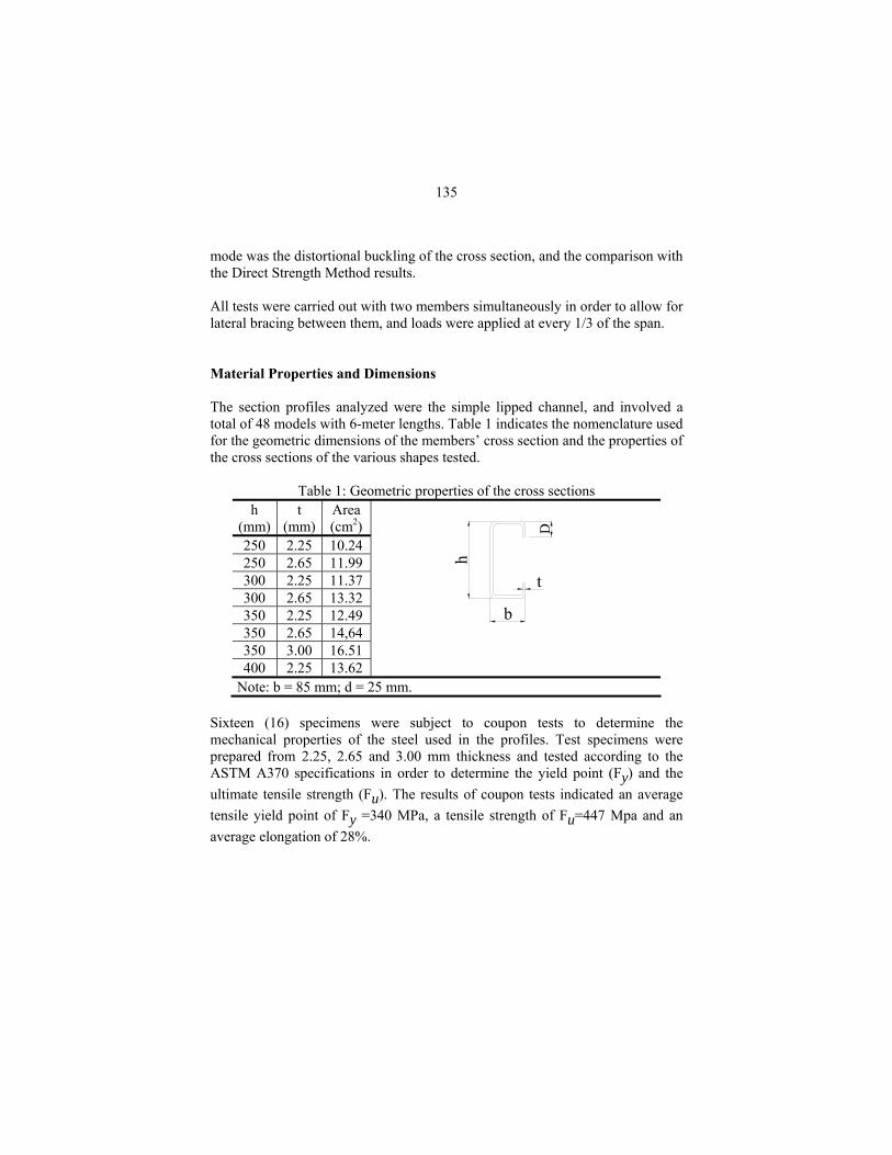
mode was the distortional buckling of the cross section, and the comparison with the Direct Strength Method results. All tests were carried out with two members simultaneously in order to allow for lateral bracing between them, and loads were applied at every 1/3 of the span. Material Properties and Dimensions The section profiles analyzed were the simple lipped channel, and involved a total of 48 models with 6-meter lengths. Table 1 indicates the nomenclature used for the geometric dimensions of the members’ cross section and the properties of the cross sections of the various shapes tested.
Table 1: Geometric properties of the cross sections h
(mm) t
(mm) Area (cm2)
250 2.25 10.24 250 2.65 11.99 300 2.25 11.37 300 2.65 13.32 350 2.25 12.49 350 2.65 14,64 350 3.00 16.51 400 2.25 13.62
b
h
t
D
Note: b = 85 mm; d = 25 mm. Sixteen (16) specimens were subject to coupon tests to determine the mechanical properties of the steel used in the profiles. Test specimens were prepared from 2.25, 2.65 and 3.00 mm thickness and tested according to the ASTM A370 specifications in order to determine the yield point (Fy) and the ultimate tensile strength (Fu). The results of coupon tests indicated an average tensile yield point of Fy =340 MPa, a tensile strength of Fu=447 Mpa and an average elongation of 28%.
136
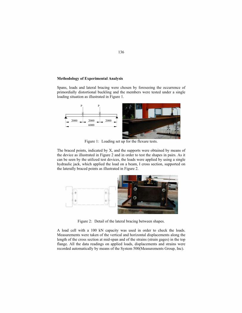
Methodology of Experimental Analysis Spans, loads and lateral bracing were chosen by foreseeing the occurrence of primordially distortional buckling and the members were tested under a single loading situation as illustrated in Figure 1.
20006000
2000 2000
PP
Figure 1: Loading set up for the flexure tests. The braced points, indicated by X, and the supports were obtained by means of the device as illustrated in Figure 2 and in order to test the shapes in pairs. As it can be seen by the utilized test devices, the loads were applied by using a single hydraulic jack, which applied the load on a beam, I cross section, supported on the laterally braced points as illustrated in Figure 2.
Figure 2: Detail of the lateral bracing between shapes. A load cell with a 100 kN capacity was used in order to check the loads. Measurements were taken of the vertical and horizontal displacements along the length of the cross section at mid-span and of the strains (strain gages) in the top flange. All the data readings on applied loads, displacements and strains were recorded automatically by means of the System 500(Measurements Group, Inc).
137
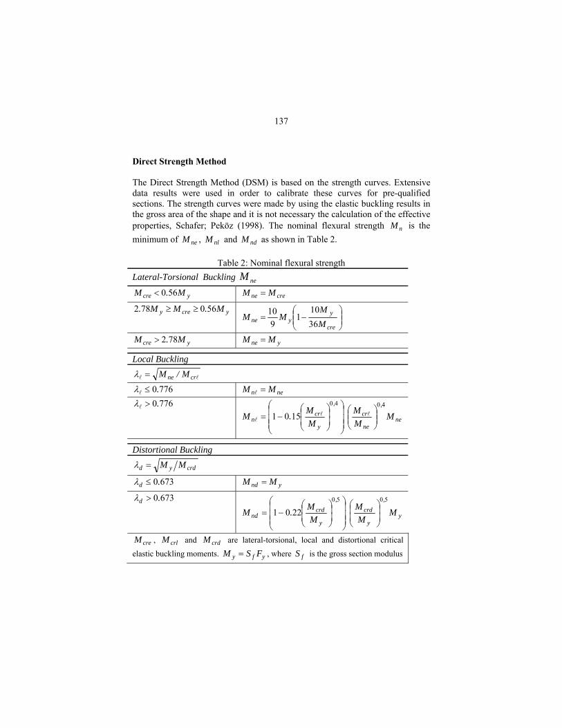
Direct Strength Method The Direct Strength Method (DSM) is based on the strength curves. Extensive data results were used in order to calibrate these curves for pre-qualified sections. The strength curves were made by using the elastic buckling results in the gross area of the shape and it is not necessary the calculation of the effective properties, Schafer; Peköz (1998). The nominal flexural strength nM is the minimum of neM , nlM and ndM as shown in Table 2.
Table 2: Nominal flexural strength Lateral-Torsional Buckling neM
ycre M.M 560< crene MM =
ycrey M.MM. 560782 ≥≥ ⎟⎟⎠
⎞⎜⎜⎝
⎛−=
cre
yyne M
MMM
3610
19
10
ycre M.M 782> yne MM =
Local Buckling
crne M/M=λ 7760.≤λ nen MM = 7760.>λ
ne
,
ne
cr,
y
crn M
MM
MM.M
4040
1501 ⎟⎟⎠
⎞⎜⎜⎝
⎛
⎟⎟⎟
⎠
⎞
⎜⎜⎜
⎝
⎛
⎟⎟⎠
⎞⎜⎜⎝
⎛−=
Distortional Buckling
crdyd MM=λ
6730.d ≤λ ynd MM =
6730.d >λ
y
,
y
crd,
y
crdnd M
MM
MM.M
5050
2201 ⎟⎟⎠
⎞⎜⎜⎝
⎛
⎟⎟⎟
⎠
⎞
⎜⎜⎜
⎝
⎛
⎟⎟⎠
⎞⎜⎜⎝
⎛−=
creM , crlM and crdM are lateral-torsional, local and distortional critical
elastic buckling moments. yfy FSM = , where fS is the gross section modulus

138
Test Results Table 3 shows the results of the ultimate load (Pultimate) obtained in all the tested sets and the ultimate moment (Multimate), which correspond to the measured value of Pultimate multiplied by two meters, based on the loading set up used in these tests.
Table 3: Results obtained in the tests Set C section
(hxbxdxt in mm)Pultimate (kN) Mean
Value (kN)Multimate (kNm)
1 250x85x25x2.25 8.85 2 250x85x25x2.25 13.18 3 250x85x25x2.25 11.41 11.14 22.29 4 250x85x25x2.65 13.45 5 250x85x25x2.65 13.65 6 250x85x25x2.65 15.25 14.12 28.23 7 300x85x25x2.25 Lost 8 300x85x25x2.25 15.88 9 300x85x25x2.25 16.10 15.99 31.98
10 300x85x25x2.65 Lost 11 300x85x25x2.65 17.38 12 300x85x25x2.65 17.08 17.23 34.46 13 350x85x25x2.25 16.73 14 350x85x25x2.25 18.28 15 350x85x25x2.25 16.48 17.16 34.32 16 350x85x25x2.65 16.53 17 350x85x25x2.65 Lost 18 350x85x25x2.65 16.78 16.66 33.32 19 350x85x25x3.00 23.15 20 350x85x25x3.00 23.40 21 350x85x25x3.00 23.23 23.26 46.52 22 400x85x25x2.25 17.90 23 400x85x25x2.25 18.60 24 400x85x25x2.25 18.77 18.42 36.84
139
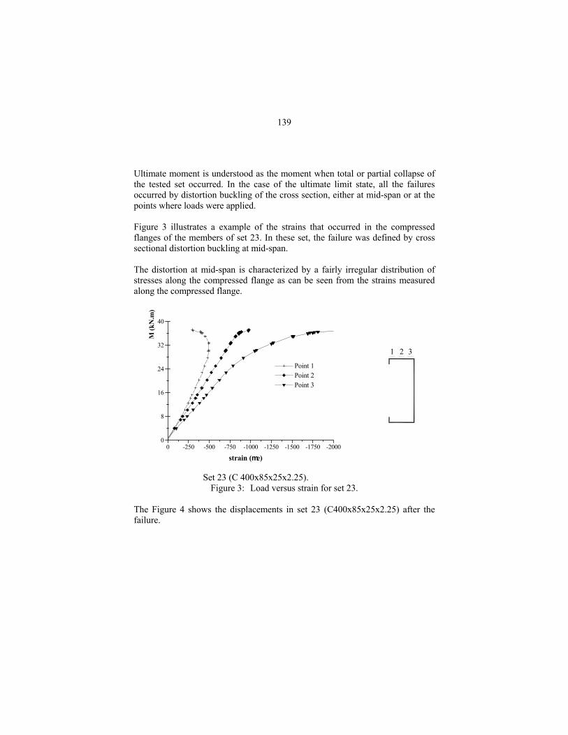
Ultimate moment is understood as the moment when total or partial collapse of the tested set occurred. In the case of the ultimate limit state, all the failures occurred by distortion buckling of the cross section, either at mid-span or at the points where loads were applied. Figure 3 illustrates a example of the strains that occurred in the compressed flanges of the members of set 23. In these set, the failure was defined by cross sectional distortion buckling at mid-span. The distortion at mid-span is characterized by a fairly irregular distribution of stresses along the compressed flange as can be seen from the strains measured along the compressed flange.
0
8
16
24
32
40
0 -250 -500 -750 -1000 -1250 -1500 -1750 -2000
M
(kN
.m)
Point 1 Point 2 Point 3
strain (me)
1 2 3
Set 23 (C 400x85x25x2.25). Figure 3: Load versus strain for set 23.
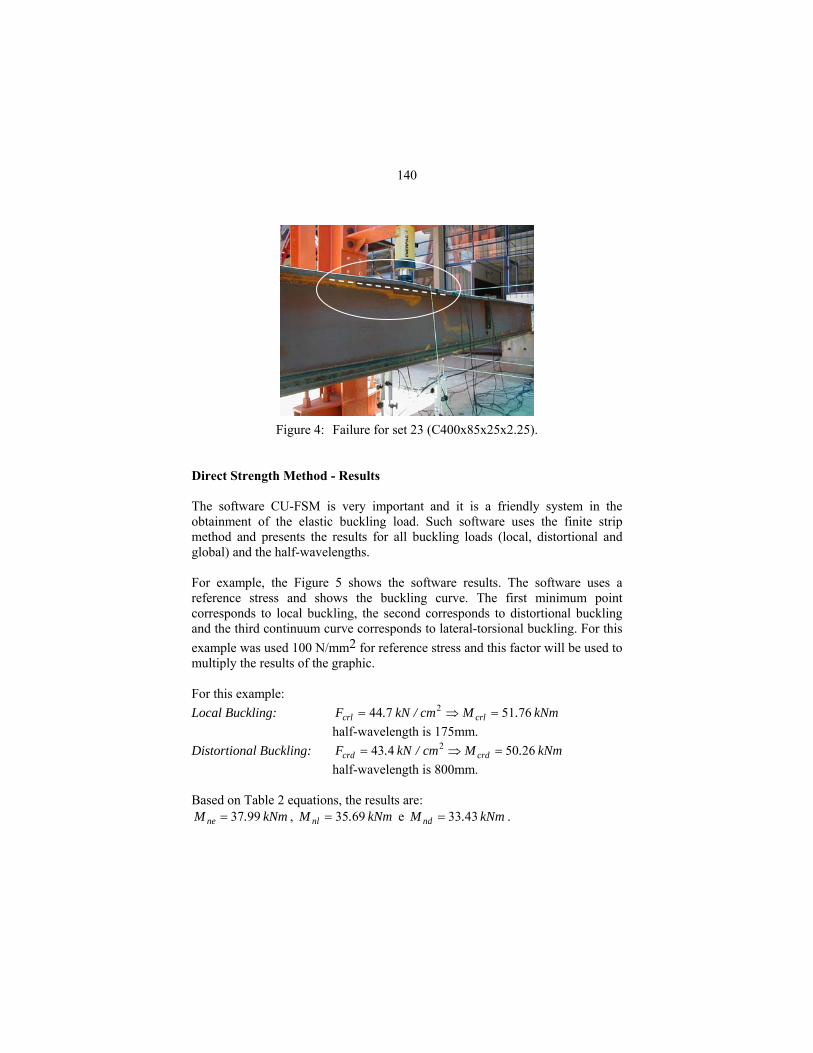
The Figure 4 shows the displacements in set 23 (C400x85x25x2.25) after the failure.
140
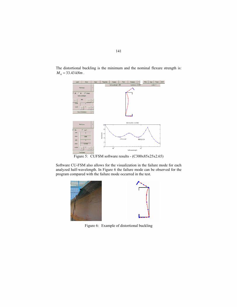
Figure 4: Failure for set 23 (C400x85x25x2.25). Direct Strength Method - Results The software CU-FSM is very important and it is a friendly system in the obtainment of the elastic buckling load. Such software uses the finite strip method and presents the results for all buckling loads (local, distortional and global) and the half-wavelengths. For example, the Figure 5 shows the software results. The software uses a reference stress and shows the buckling curve. The first minimum point corresponds to local buckling, the second corresponds to distortional buckling and the third continuum curve corresponds to lateral-torsional buckling. For this example was used 100 N/mm2 for reference stress and this factor will be used to multiply the results of the graphic. For this example: Local Buckling: kNm .Mcm/kN .F crlcrl 7651744 2 =⇒= half-wavelength is 175mm. Distortional Buckling: kNm .Mcm/kN .F crdcrd 2650443 2 =⇒= half-wavelength is 800mm. Based on Table 2 equations, the results are:
kNm .M ne 9937= , kNm .M nl 6935= e kNm .M nd 4333= .
141
The distortional buckling is the minimum and the nominal flexure strength is: kNm .M n 4333= .
Figure 5: CUFSM software results - (C300x85x25x2.65)
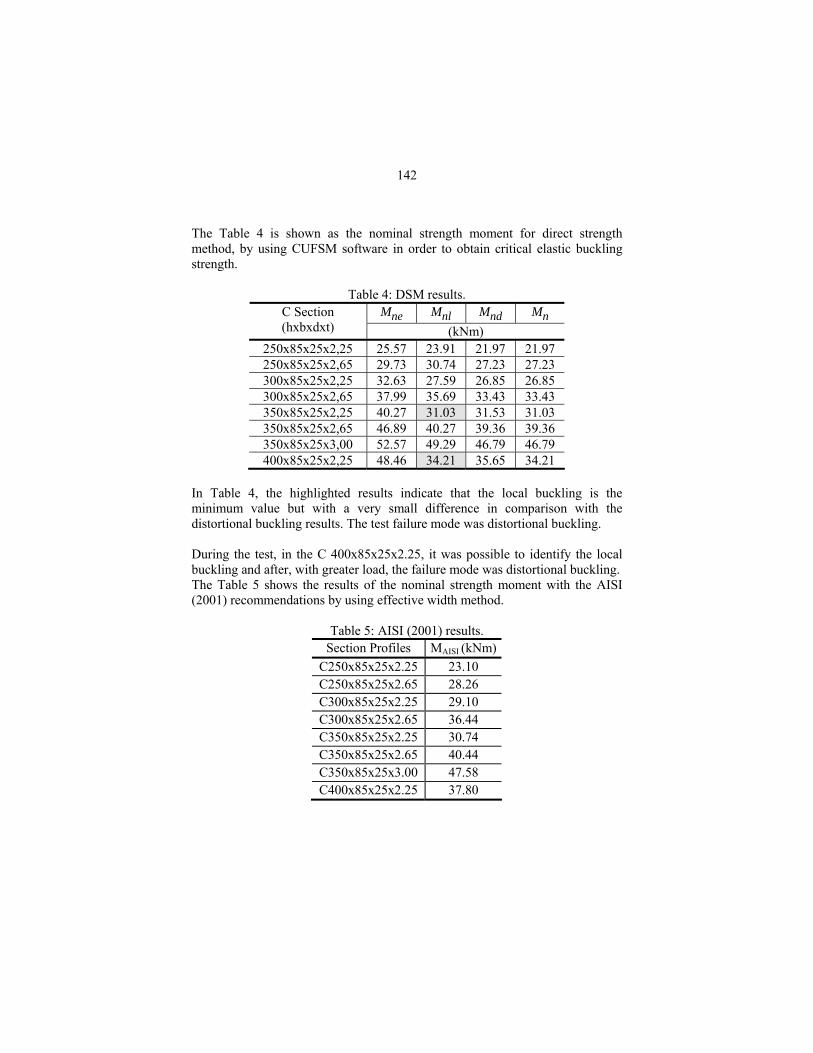
Software CU-FSM also allows for the visualization in the failure mode for each analyzed half-wavelength. In Figure 6 the failure mode can be observed for the program compared with the failure mode occurred in the test.
Figure 6: Example of distortional buckling
142
The Table 4 is shown as the nominal strength moment for direct strength method, by using CUFSM software in order to obtain critical elastic buckling strength.
Table 4: DSM results. Mne Mnl Mnd Mn C Section
(hxbxdxt) (kNm) 250x85x25x2,25 25.57 23.91 21.97 21.97 250x85x25x2,65 29.73 30.74 27.23 27.23 300x85x25x2,25 32.63 27.59 26.85 26.85 300x85x25x2,65 37.99 35.69 33.43 33.43 350x85x25x2,25 40.27 31.03 31.53 31.03 350x85x25x2,65 46.89 40.27 39.36 39.36 350x85x25x3,00 52.57 49.29 46.79 46.79 400x85x25x2,25 48.46 34.21 35.65 34.21
In Table 4, the highlighted results indicate that the local buckling is the minimum value but with a very small difference in comparison with the distortional buckling results. The test failure mode was distortional buckling. During the test, in the C 400x85x25x2.25, it was possible to identify the local buckling and after, with greater load, the failure mode was distortional buckling. The Table 5 shows the results of the nominal strength moment with the AISI (2001) recommendations by using effective width method.
Table 5: AISI (2001) results. Section Profiles MAISI (kNm)
C250x85x25x2.25 23.10 C250x85x25x2.65 28.26 C300x85x25x2.25 29.10 C300x85x25x2.65 36.44 C350x85x25x2.25 30.74 C350x85x25x2.65 40.44 C350x85x25x3.00 47.58 C400x85x25x2.25 37.80
143
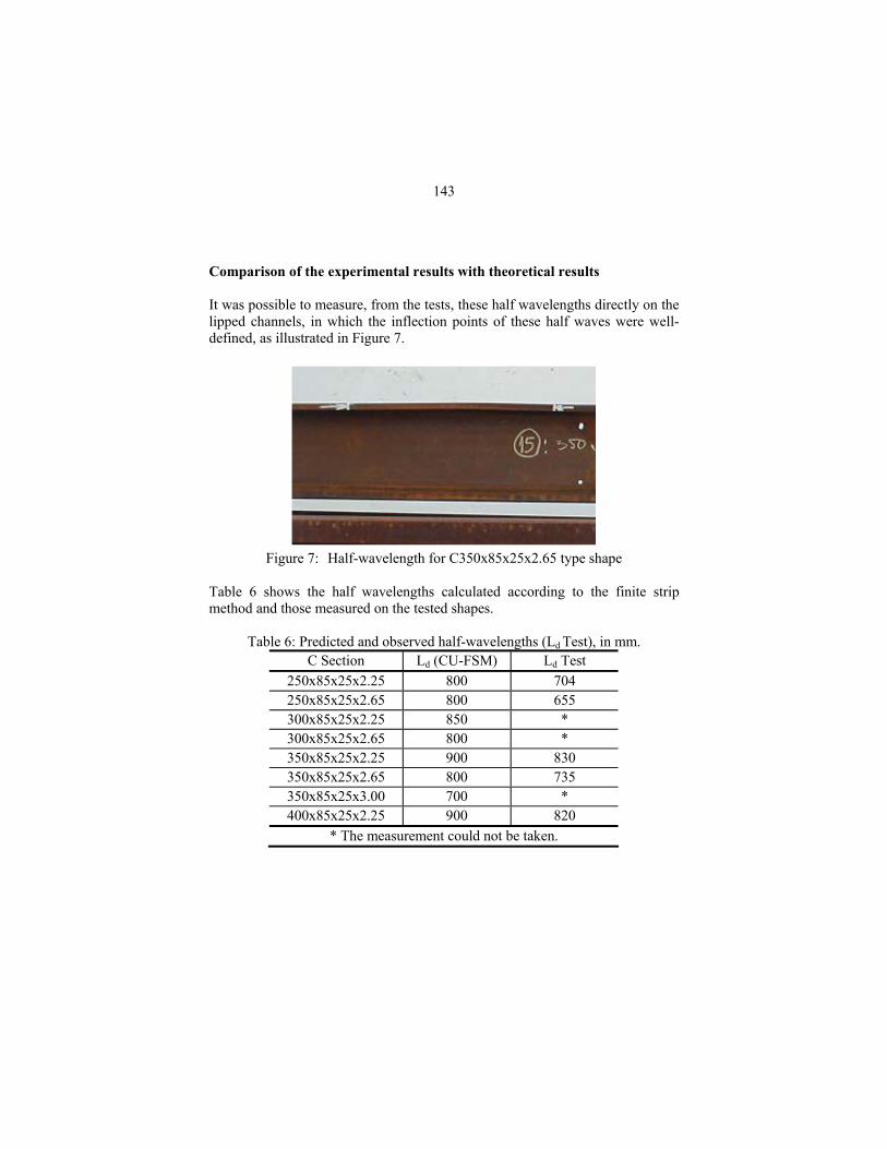
Comparison of the experimental results with theoretical results It was possible to measure, from the tests, these half wavelengths directly on the lipped channels, in which the inflection points of these half waves were well-defined, as illustrated in Figure 7.
Figure 7: Half-wavelength for C350x85x25x2.65 type shape
Table 6 shows the half wavelengths calculated according to the finite strip method and those measured on the tested shapes.
Table 6: Predicted and observed half-wavelengths (Ld Test), in mm. C Section Ld (CU-FSM) Ld Test
250x85x25x2.25 800 704 250x85x25x2.65 800 655 300x85x25x2.25 850 * 300x85x25x2.65 800 * 350x85x25x2.25 900 830 350x85x25x2.65 800 735 350x85x25x3.00 700 * 400x85x25x2.25 900 820
* The measurement could not be taken.
144
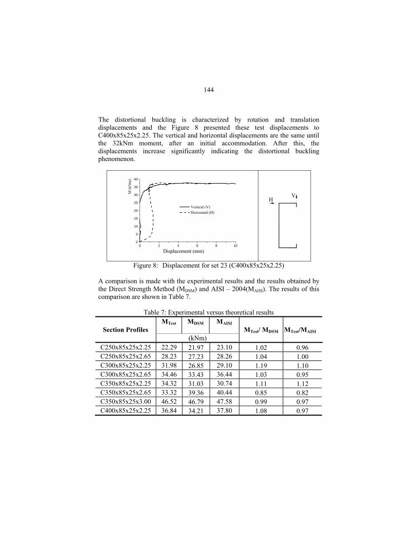
The distortional buckling is characterized by rotation and translation displacements and the Figure 8 presented these test displacements to C400x85x25x2.25. The vertical and horizontal displacements are the same until the 32kNm moment, after an initial accommodation. After this, the displacements increase significantly indicating the distortional buckling phenomenon.
0
5
10
15
20
25
30
35
40
0 2 4 6 8 10
Vertical (V) Horizontal (H)
Displacement (mm)
M (k
Nm
)
VH
Figure 8: Displacement for set 23 (C400x85x25x2.25) A comparison is made with the experimental results and the results obtained by the Direct Strength Method (MDSM) and AISI – 2004(MAISI). The results of this comparison are shown in Table 7.
Table 7: Experimental versus theoretical results MTest MDSM MAISI
MTest/MAISI
Section Profiles (kNm)
MTest/ MDSM
C250x85x25x2.25 22.29 21.97 23.10 1.02 0.96 C250x85x25x2.65 28.23 27.23 28.26 1.04 1.00 C300x85x25x2.25 31.98 26.85 29.10 1.19 1.10 C300x85x25x2.65 34.46 33.43 36.44 1.03 0.95 C350x85x25x2.25 34.32 31.03 30.74 1.11 1.12 C350x85x25x2.65 33.32 39.36 40.44 0.85 0.82 C350x85x25x3.00 46.52 46.79 47.58 0.99 0.97 C400x85x25x2.25 36.84 34.21 37.80 1.08 0.97
145
The experimental, Direct Strength Method and AISI results indicate a good correlation, except to the C300x85x25x2.25 with low value of MDSM and of C350x85x25x2.65, with low value to tests results. All the other results presented a good correlation. Conclusions The main objective of this paper was to study the distortional buckling in the cold-formed steel shapes caused by bending and to compare the test results with Direct Strength Method.
1- The failure mode of distortion buckling by cross section was perfectly characterized in all tests.
2- Non-uniform distribution of stresses along the flange was also evidenced, Figure 3, and characterized by the distortional buckling.
3- During the test for the C400x85x25x2.25, we can observe the local buckling of the web and after the distortional buckling occurred. This indicated that the strength of local and distortional buckling is very similar.
4- The current results are very good in comparison with the results according to AISI recommendation and the Direct Strength Method. The importance of this method in the buckling analysis is confirmed and highlighted by its very easy application, in comparison with traditional methods.
Acknowledgment
The authors are grateful for the financial support provided by FAPESP and CAPES.
146
References AMERICAN IRON AND STEEL INSTITUTE (2001). ) Cold formed steel design manual. AISI, Washington. AMERICAN IRON AND STEEL INSTITUTE (2004). Appendix 1 – Design of cold-formed steel structural members using the direct strength method. Washington, (http://www.ce.jhu.edu/bschafer/). GONÇALVES, R. M. ; JAVARONI, C. E. ; MALITE, M. . Experimental analysis of cold-formed steel channel and lipped-channel profiles connected to roof panel: R-factor analysis. In: LaBOUBE, R.A.; YU, W.-W.. (Org.). Recent research and developments in cold-formed steel design and construction. Rolla, 2002, v. 1, p. 523-535. SCHAFER, B. W. (1999) CU-FSM Users manual v1.0d. Cornell University. SCHAFER, B. W.; PEKÖZ, T.; (1998) Direct strength prediction of cold-formed steel member using numerical elastic buckling solutions. In: Fourteenth International Specialty Conference on Cold-Formed Steel Structures – Design and Construction. St. Louis, Missouri, USA. Proceedings. HANCOCK, G. J.; KWON, Y.B.; BERNARD, E.S. (1994) Strength design curves for thin-walled sections undergoing distortional buckling. Journal of Constructional Steel Research, v.31, p.169-186. HANCOCK, G., Murray, T.M., Ellifritt, D.S., (2001), Cold-Formed Steel Structures to the AISI Specification. Marcell-Dekker, New York. YU, W.W. (2000) Cold-Formed Steel Design. John Wiley& Sons, Inc.
Copyright © 2022 FDOKUMEN


![05-03ChapGere[1] | Bending | Beam (Structure) - xdocs.net](https://static.fdokumen.com/doc/165x107/6323c1d9be5419ea700ebf89/05-03chapgere1-bending-beam-structure-xdocsnet.jpg)