LOCAL BUCKLING AND SHIFT OF EFFECTIVE CENTROID ...
14
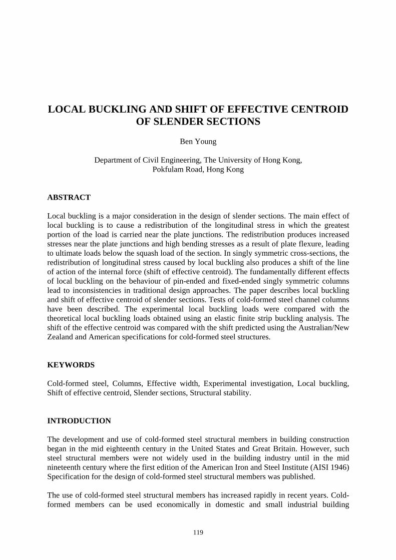
119 LOCAL BUCKLING AND SHIFT OF EFFECTIVE CENTROID OF SLENDER SECTIONS Ben Young Department of Civil Engineering, The University of Hong Kong, Pokfulam Road, Hong Kong ABSTRACT Local buckling is a major consideration in the design of slender sections. The main effect of local buckling is to cause a redistribution of the longitudinal stress in which the greatest portion of the load is carried near the plate junctions. The redistribution produces increased stresses near the plate junctions and high bending stresses as a result of plate flexure, leading to ultimate loads below the squash load of the section. In singly symmetric cross-sections, the redistribution of longitudinal stress caused by local buckling also produces a shift of the line of action of the internal force (shift of effective centroid). The fundamentally different effects of local buckling on the behaviour of pin-ended and fixed-ended singly symmetric columns lead to inconsistencies in traditional design approaches. The paper describes local buckling and shift of effective centroid of slender sections. Tests of cold-formed steel channel columns have been described. The experimental local buckling loads were compared with the theoretical local buckling loads obtained using an elastic finite strip buckling analysis. The shift of the effective centroid was compared with the shift predicted using the Australian/New Zealand and American specifications for cold-formed steel structures. KEYWORDS Cold-formed steel, Columns, Effective width, Experimental investigation, Local buckling, Shift of effective centroid, Slender sections, Structural stability. INTRODUCTION The development and use of cold-formed steel structural members in building construction began in the mid eighteenth century in the United States and Great Britain. However, such steel structural members were not widely used in the building industry until in the mid nineteenth century where the first edition of the American Iron and Steel Institute (AISI 1946) Specification for the design of cold-formed steel structural members was published. The use of cold-formed steel structural members has increased rapidly in recent years. Cold- formed members can be used economically in domestic and small industrial building
-
Upload
khangminh22 -
Category
Documents
-
view
0 -
download
0
Transcript of LOCAL BUCKLING AND SHIFT OF EFFECTIVE CENTROID ...
119
LOCAL BUCKLING AND SHIFT OF EFFECTIVE CENTROID OF SLENDER SECTIONS
Ben Young
Department of Civil Engineering, The University of Hong Kong,
Pokfulam Road, Hong Kong
ABSTRACT Local buckling is a major consideration in the design of slender sections. The main effect of local buckling is to cause a redistribution of the longitudinal stress in which the greatest portion of the load is carried near the plate junctions. The redistribution produces increased stresses near the plate junctions and high bending stresses as a result of plate flexure, leading to ultimate loads below the squash load of the section. In singly symmetric cross-sections, the redistribution of longitudinal stress caused by local buckling also produces a shift of the line of action of the internal force (shift of effective centroid). The fundamentally different effects of local buckling on the behaviour of pin-ended and fixed-ended singly symmetric columns lead to inconsistencies in traditional design approaches. The paper describes local buckling and shift of effective centroid of slender sections. Tests of cold-formed steel channel columns have been described. The experimental local buckling loads were compared with the theoretical local buckling loads obtained using an elastic finite strip buckling analysis. The shift of the effective centroid was compared with the shift predicted using the Australian/New Zealand and American specifications for cold-formed steel structures. KEYWORDS Cold-formed steel, Columns, Effective width, Experimental investigation, Local buckling, Shift of effective centroid, Slender sections, Structural stability. INTRODUCTION The development and use of cold-formed steel structural members in building construction began in the mid eighteenth century in the United States and Great Britain. However, such steel structural members were not widely used in the building industry until in the mid nineteenth century where the first edition of the American Iron and Steel Institute (AISI 1946) Specification for the design of cold-formed steel structural members was published. The use of cold-formed steel structural members has increased rapidly in recent years. Cold-formed members can be used economically in domestic and small industrial building

120
construction and other light gauge structures. As compared to thicker hot-rolled members, cold-formed members provide enhanced strength to weight ratio and ease of construction. The manufacturing process of fabricating cold-formed members usually involves brake-pressing and roll-forming of steel sheets and strip to produce a wide range cross-section shapes. Cold-formed sections are normally thinner than hot-rolled sections and have a different forming process. Therefore, the buckling and material behaviour can be quite different. Cold-formed columns commonly fail in two distinct modes of buckling, they are local buckling and overall buckling. Interaction of these two modes may occur in some cases. Both local and overall instability represent common causes of structural failure. Distortional buckling is also one of the modes of failure for some sections. As a consequence, structural instability has grown into a major research area, where both analytical and experimental investigation have been undertaken to overcome the difficulties of the design of cold-formed steel structural members. Local buckling plays an important role in the design of slender sections. There is a fundamental different on the behaviour of pin-ended and fixed-ended locally buckled singly symmetric columns. This is due to the shift of effective centroid of singly symmetric slender sections. The purpose of this paper is to describe the local buckling and the shift of effective centroid of slender sections. The concept of effective width and effective width equations are also described. The experimental local buckling loads were compared with the theoretical local buckling loads of cold-formed steel channel columns. The local, distortional and overall buckling of the channel columns are presented. The shift of effective centroid of singly and doubly symmetric cross-sections is also described in this paper. The shift of the effective centroid of the channel columns was compared with the shift predicted using the Australian/New Zealand (Aust/NZ 1996) Standard for cold-formed steel structures and the American Iron and Steel Institute (AISI 1996) Specification for the design of cold-formed steel structural members. LOCAL BUCKLING General Local buckling involves deformation of the component plate elements of the section, with the plate junctions remaining straight as shown in Fig. 1, and is associated with a half-wavelength which compares with the depth of the section. Fig. 2 shows a plain channel subjected to pure compression. A photograph of a locally buckled cold-formed plain channel column compressed between fixed ends is shown in Fig. 3. The effect of local buckling plays an important role in the design of slender sections. One of the effects is that it reduces the flexural rigidity of the section and hence the member strength.

121
Figure 1: Local buckling modes of typical cross-sections in compression
Figure 2: Locally buckled plain channel in compression
Figure 3: Interaction of local and overall buckling of cold-formed steel plain channel column Concept of Effective Width and Effective Width Equations A common design procedure to determine the section strength of slender section is to use the concept of effective widths. The concept was first proposed by von Kàrmàn et al. (1932). It was introduced following the realization that local buckling of plate elements causes a concentration of the longitudinal stress near the supporting edges of a plate element. Stiffened

122
element is supported longitudinally along two edges as shown in Fig. 4a. For unstiffened element, it is only supported longitudinally along one edge, as shown in Fig 4b.
(a) Stiffened element (b) Unstiffened element
Figure 4: Stiffened and unstiffened elements von Kàrmàn suggested that the actual stress distribution at the central portion of a stiffened plate could only support very little stress, but the edge portions were capable of supporting considerable stress. Hence, for uniformly compressed element, the actual stress distribution may be replaced by two effective portions (be/2) near the supporting edges of a stiffened element, as shown in Fig. 5a. Similarly, the actual stress distribution may be replaced by one effective portion (be) near the supporting edge of an unstiffened element, as shown in Fig. 5b.
b b
bebe be
SimplySupported
SimplySupported
Idealised StressDistribution
Actual StressDistribution
Actual StressDistribution
Design Stress f
FreeEdge
/2/2
( *)
(a) Stiffened element (b) Unstiffened element
Figure 5: Stress redistribution on uniformly compressed elements after local buckling and
effective widths (be) von Kàrmàn et al. (1932) proposed the ultimate plate strength (Pu) expression as follows,

123
2tEfCtfbP yyeu == (1)
where C is an empirical constant which depended upon the Poisson ratio and the longitudinal support conditions, E is the Young’s modulus of elasticity, fy is the yield stress and t is the plate thickness. However, the effective width formula by von Kàrmàn is only valid for perfect plates. Geometric imperfections and residual stresses exist in real plates, which caused by fabrication process. Consequently, it is required to account for the reduction in strength from these imperfections. Winter has proposed and later verified experimentally (1947 and 1968) an effective width formula for stiffened compression elements, which based on a series of tests on folded thin-walled sections. The verified original formula by Winter is as follows,
⎥⎥⎦
⎤
⎢⎢⎣
⎡⎟⎠⎞
⎜⎝⎛−=
∗∗ f
Ebt
f
Etbe 415.019.1 (2)
which can be rearranged to the following expression,
⎥⎥⎦
⎤
⎢⎢⎣
⎡−=
∗∗ fp
fp
bb crcre 22.01 (3)
where f * is the design stress and pcr is the critical elastic buckling stress of a plate. Equation (3) is called the Winter effective width formula, which is a modification of von Kàrmàn formula. The term within the bracket of Eqn. (3) is to account for the effects of imperfections. The equation can be simplified to the following expression,
⎪⎪
⎩
⎪⎪
⎨
⎧
>λ≤λ
⎟⎠⎞
⎜⎝⎛
λ−
≤λ
=
673.0when0.1
22.01
673.0when1
bbe (4)
where λ is the slenderness ratio , which is determined as follows,
Ef
tb
K
∗⎟⎠⎞
⎜⎝⎛=λ
052.1 (5)
where K is the plate buckling coefficient. The buckling coefficient (K) is a function of the longitudinal edge support conditions. Equation (4) becomes widely known expression and it is used extensively in many cold-formed steel specifications today. Summary of Test Program

124
The test program described in Young (1997) and Young and Rasmussen (1998a and 1998b) provided experimental ultimate loads for cold-formed plain and lipped channel columns compressed between fixed ends and pinned ends. All test specimens were fabricated by brake-pressing from high strength zinc-coated Grade G450 with nominal yield stress of 450MPa structural steel sheet. The test program comprised four different cross-section geometries. Two series of plain channels and two series of lipped channels were tested, having a nominal thickness of 1.5mm and a nominal width of the web of 96mm for all channels. The nominal width of the lip of both lipped channels was 12mm. The flange width was either 36mm or 48mm and was the only variable in the cross-section geometry. Accordingly, the four test series were labelled P36, P48, L36 and L48 where “P” and “L” refer to “plain” and “lipped” channel respectively. The specimens were mainly tested between fixed ends at various column lengths. However, some of the specimens were tested between pinned ends using the same effective lengths as those for the fixed-ended specimens. The shortest specimen lengths complied with the SSRC guidelines (Galambos 1998) for stub column lengths, while the longest produced ley/ry ratios of approximately 130, 110, 110 and 100 for Series P36, P48, L36 and L48 respectively, where ley is the effective length for buckling about the minor y-axis and ry is the radius of gyration about the y-axis. The measured cross-section dimensions of each specimen are detailed in Young and Rasmussen (1998a and 1998b). The material properties determined from the coupon tests are summarized in Table 1. The table contains the nominal 0.2% tensile proof stress (σ0.2), the measured static 0.2% (σ0.2) and 0.5% (σ0.5) tensile proof stresses, the tensile strength (σu) as well as the Young’s modulus (E) and the elongation after fracture (ε) based on a gauge length of 50mm. The stress-strain curves obtained from the coupon tests are detailed in Young and Rasmussen (1998a and 1998b). The details of the residual stress measurements, local and overall geometric imperfections of the test specimens, and the procedure of the column tests are given in Young and Rasmussen (1998a and 1998b).
TABLE 1 NOMINAL AND MEASURED MATERIAL PROPERTIES
Local Buckling Load The experimental local buckling loads (NlExp) of the Series P36 and P48 specimens under uniform compression were determined for all fixed-ended tests, except for the long specimens whose ultimate loads were lower than the elastic local buckling load of the section. The experimental local buckling load (NlExp) was determined by plotting the load (N) against the square of a local buckling deformation and subsequently fitting a line through the test points in the post local buckling region. The intercept with the load axis resulting from the line fitted in this region was assumed to be the experimental buckling load (Venkataramaiah and Roorda
Test series Nominal Measured σ0.2 E σ0.2 σ0.5 σu ε (MPa) (GPa) (MPa) (MPa) (MPa) (%)
P36 450 210 550 560 570 10 P48 450 210 510 525 540 11 L36 450 210 515 525 540 11 L48 450 200 550 560 570 10

125
1982). The larger of the web deformation and the average of the deformations at the free edge of the flanges at mid-length was used for the plots. The mean and standard deviation (S.D.) of the experimental local buckling loads for all specimens of each series are given in Table 2.
TABLE 2 EXPERIMENTAL AND THEORETICAL LOCAL BUCKLING LOADS
The theoretical elastic local buckle half-wavelength (l) and elastic local buckling load (NlTh) were obtained using a finite strip buckling analysis (Hancock 1978). The results are also given in Table 2. The average measured cross-section dimensions of the fixed-ended specimens for each series as well as the measured values of the base metal thickness and Young’s modulus were used to determine the theoretical results. It follows from the table that the mean ratio of the experimental local buckling load to the theoretical local buckling load (NlExp / NlTh) was 1.00 and 0.98 for test Series P36 and P48 respectively and that the standard deviations (S.D.) of the same ratios were 0.01 and 0.00 respectively. The theoretical and experimental local buckling loads were very close with a maximum difference of 0.7kN (1.6%) and 0.5kN (1.4%) for Series P36 and P48 respectively. This result indicates that the finite strip buckling analysis was in excellent agreement with the experimental local buckling loads. BUCKLING MODES FOR COMPRESSION MEMBERS In designing cold-formed steel compression members, it is important to recognize the different buckling modes. Four buckling modes were encountered in the tests: • Local buckling • Distortional buckling • Overall flexural buckling • Overall flexural-torsional buckling A finite strip buckling analysis was used to investigate the possible buckling modes for Series P36, P48, L36 and L48. The computer program THIN-WALL (Papangelis and Hancock 1995) was used to generate plots of buckling stress versus buckle half-wavelength, as shown in Figs 6a, 6b, 6c and 6d for Series P36, P48, L36 and L48 respectively. The average values of the measured cross-section dimensions of the fixed-ended test specimens and the measured material properties were used in the analysis. The corner radii (ri) were negligible as a result of the brake-pressing fabrication procedure and were not modelled in the analysis. The residual stresses were also ignored. In the buckling analysis, the plain and lipped channels were subjected to uniform compression. For the plain channels, the minimum local buckling stresses of 176.7MPa and 128.1MPa occurred at half-wavelengths of 110mm and 130mm corresponding for Series P36 and P48 respectively, as shown in Figs 6a and 6b. At long half-wavelengths, flexural-torsional
Test series Experimental Theoretical Comparison NlExp NlTh l NlExp / NlTh Mean S.D. Mean S.D. (kN) (kN) (mm)
P36 43.4 0.36 43.6 110 1.00 0.01 P48 35.4 0.17 36.1 130 0.98 0.00
Note: 1 kip = 4.45kN; S.D. = Standard Deviation.

126
buckling occurred up to 3455mm, corresponding to a buckling stress of 43.4MPa, beyond which flexural buckling occurred, as shown in Fig 6b for Series P48. Flexural buckling always occurred at long half-wavelengths for Series P36, as shown in Fig 6a. The results of the buckling analysis of the lipped Series L36 channels are shown in Fig. 6c. The local buckling stress of 251.9MPa and the distortional buckling stress of 390.1MPa occurred at half-wavelengths of 75mm and 315mm respectively. Due to the local buckling stress was lower than the distortional buckling stress, the lipped channel section was likely to undergo local buckling before distortional buckling at intermediate column lengths. At long half-wavelengths, flexural-torsional buckling occurred up to 1920mm corresponding to a buckling stress of 106.5MPa, beyond which flexural buckling occurred. The results for Series L48 (which had wider flanges than the Series L36) followed a similar trend, the local buckling stress of 231.3MPa and the distortional buckling stress of 311.0MPa occurred at half-wavelengths of 75mm and 380mm respectively. At long half-wavelengths, flexural-torsional buckling occurred up to 4645mm corresponding buckling stress of 30.2MPa, beyond which flexural buckling occurred.
Figure 6a: Finite strip buckling analysis for compression member of Series P36
Figure 6b: Finite strip buckling analysis for compression member of Series P48
10 100 1000 100000
80
160
240
320
720
800
Buck
ling
Stre
ss(M
Pa)
Buckle Half-Wavelength (mm)20 50 200 500 2000 5000
400
480
560
640
= 2.1x10 MPaν = 0.3
36
= 176.7MPaol
110mm
f
96
5
LocalBuckling
FlexuralBuckling
E
10 100 1000 100000
80
160
240
320
400
480
560
640
720
800
Buck
ling
Stre
ss(M
Pa)
Buckle Half-Wavelength (mm)20 50 200 500 2000 5000
96
482.1x10 MPa
ν = 0.3
5
= 128.1MPaol
130mm
f
LocalBuckling
E =
(43.4MPa)
Flexural-torsionalBuckling
FlexuralBuckling
3455mm
t = 1.5 mm
t = 1.5 mm

127
Figure 6c: Finite strip buckling analysis for compression member of Series L36
Figure 6d: Finite strip buckling analysis for compression member of Series L48
SHIFT OF EFFECTIVE CENTROID
General The fundamentally different effects of local buckling on the behaviour of pin-ended and fixed-ended singly symmetric columns lead to inconsistencies in traditional design approaches. In the major codes of practice for cold-formed steel structures, full or partial rotational end restraints are accounted for solely by using effective lengths. Furthermore, the design strength of singly symmetric columns is reduced irrespective of the end support conditions to account for bending induced in pin-ended columns by the shift of the line of action of the internal force (shift of effective centroid). This procedure is not rational for fixed-ended singly symmetric columns, which may remain straight after local buckling. Singly Symmetric Cross-section
10 100 1000 100000
80
160
240
320
400
480
560
640
720
800
Buck
ling
Stre
ss(M
Pa)
Buckle Half-Wavelength (mm)20 50 200 500 2000 5000
96
362.1x10 MPa
ν = 0.3
5
75mm
12
315mm
LocalBuckling
DistortionalBuckling
f
odf = 390.1MPa
= 251.9MPaol
E =
(106.5MPa)
FlexuralBuckling
Flexural-torsionalBuckling
1920mm
10 100 1000 100000
80
160
240
320
400
480
560
640
720
800
Buck
ling
Stre
ss(M
Pa)
Buckle Half-Wavelength (mm)20 50 200 500 2000 5000
96
48
2.0x10 MPaν = 0.3
= 231.3MPaol
75mm
12
380mm
LocalBuckling
DistortionalBuckling
f
5 Flexural-torsionalBuckling
E =
odf = 311.0MPa
4645mm (30.2MPa)
FlexuralBuckling
t = 1.5 mm
t = 1.5 mm

128
Cold-formed members are cold-rolled or brake-pressed into structural shapes. As a result, open cold-formed sections are usually singly-, point- or non-symmetric. The most common types of cross-section are singly-symmetric plain and lipped channels and point-symmetric plain and lipped Z-sections. The boundary conditions for singly symmetric columns are important in the design of thin-walled columns. Local buckling of singly symmetric columns, such as channel sections, may cause overall bending of the column depending on whether the section is compressed between pinned or fixed ends. A uniformly compressed channel section undergoes a shift in the line of action of the internal force when the section locally buckles, as demonstrated in Fig 7. Rhodes and Harvey (1977) explained that the shift results from the asymmetric redistribution of longitudinal stress following the development of local buckling deformations, and leads to an eccentricity of the applied load in pin-ended channels. Hence, local buckling of pin-ended channel columns induces overall bending, as shown in Fig. 8. However, this phenomenon does not occur in fixed-ended channel columns as showed by analytical (Rasmussen and Hancock 1993) and experimental (Young and Rasmussen 1999a) studies. In this case, the shift in the line of action of the internal force is balanced by a shift in the line of action of the external force, and consequently local buckling does not induce overall bending, as shown in Fig. 9. Thus, the behaviour of pin-ended and fixed-ended singly symmetric columns is fundamentally different.
Before local buckling After local bucklingEffective widthrepresentation
G eom etric centro idEffective centroid
Figure 7: Stress redistribution of singly symmetric section under uniform compression with effective width representation

129
Figure 8: Locally buckled pin-ended channel column
Figure 9: Locally buckled fixed-ended channel column Doubly Symmetric Cross-section In locally buckled doubly symmetric columns, the redistribution of longitudinal stress does not cause a shift in the line of action of the internal force because of the section symmetry, as shown in Fig. 10. Therefore, local buckling of doubly symmetric columns does not induce overall bending, regardless of the support conditions. The behaviour of locally buckled singly symmetric columns compressed between fixed ends is similar to that of locally buckled doubly symmetric columns compressed between fixed or pinned ends.

130
Before local buckling After local buckling
G eom etric centro idEffective centroid
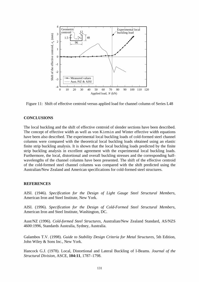
Figure 10: Stress redistribution of doubly symmetric section under uniform compression Measurement of Shift of Effective Centroid The shift of the effective centroid of channel columns has been experimentally investigated by Young and Rasmussen (1999b). Special fixed-ended bearings were used to measure the shift of the effective centroid of the channel column of Series L48 having column length of 1000mm. The details of the fixed-ended bearings are given in Young and Rasmussen (2003). The experimental shift (eS) of the line of action of the applied load (N), calculated as the ratio of the measured minor axis end moment divided by the measured applied load is shown in Fig. 11. The shift is compared with the shift predicted using the Australian/New Zealand Standard (Aust/NZ 1996) and the American Iron and Steel Institute Specification (AISI 1996) for cold-formed steel structures. It follows that the predicted shift was initially toward the lip (positive values of eS) but changed at a load of approximately 52kN to shift toward the web, contrary to the measured shift. At ultimate load, the measured shift was 2.7mm toward the lips while the predicted shift was 2.0mm toward the web. Young and Rasmussen (1998b) showed the inaccuracy of the predicted shift leads to abnormalities in the design strength curves for lipped channel columns. Young and Rasmussen (1999b) proposed simple modifications to the effective width design rules in the American Iron and Steel Institute Specification (AISI 1996) for cold-formed steel structures. The proposed effective width design rules provide good agreement between the experimental and the predicted shifts of the effective centroid for lipped channels. The modifications are shown to produce more accurate design strengths for lipped channel columns.
131
0 10 20 30 40 50 60 70 80 90 100 110 120-4
-3
-2
-1
0
1
2
3
4
e s(m
m)
N (kN)
es
9648
12Geometriccentroid
1.5
Experimental localbuckling load
Measured valuesAust./NZ & AISI
Applied load,
Shift
ofth
eef
fect
ive
cent
roid
,
Figure 11: Shift of effective centroid versus applied load for channel column of Series L48
CONCLUSIONS The local buckling and the shift of effective centroid of slender sections have been described. The concept of effective width as well as von Kàrmàn and Winter effective width equations have been also described. The experimental local buckling loads of cold-formed steel channel columns were compared with the theoretical local buckling loads obtained using an elastic finite strip buckling analysis. It is shown that the local buckling loads predicted by the finite strip buckling analysis in excellent agreement with the experimental local buckling loads. Furthermore, the local, distortional and overall buckling stresses and the corresponding half-wavelengths of the channel columns have been presented. The shift of the effective centroid of the cold-formed steel channel columns was compared with the shift predicted using the Australian/New Zealand and American specifications for cold-formed steel structures. REFERENCES AISI. (1946). Specification for the Design of Light Gauge Steel Structural Members, American Iron and Steel Institute, New York. AISI. (1996). Specification for the Design of Cold-Formed Steel Structural Members, American Iron and Steel Institute, Washington, DC. Aust/NZ (1996). Cold-formed Steel Structures, Australian/New Zealand Standard, AS/NZS 4600:1996, Standards Australia, Sydney, Australia. Galambos T.V. (1998). Guide to Stability Design Criteria for Metal Structures, 5th Edition, John Wiley & Sons Inc., New York. Hancock G.J. (1978). Local, Distortional and Lateral Buckling of I-Beams. Journal of the Structural Division, ASCE, 104:11, 1787–1798.

132
Kàrmàn T. von, Sechler E.E. and Donnell L.H. (1932). The Strength of Thin Plates in Compression. Transactions, Applied Mechanics Division, ASME, 54, APM 54–5, 53–57. Papangelis J.P. and Hancock G.J. (1995). Computer Analysis of Thin-Walled Structural Members. Computers and Structures, 56:1, 157–176. Rasmussen K.J.R. and Hancock G.J. (1993). The Flexural Behaviour of Fixed-ended Channel Section Columns. Thin-Walled Structures, 17:1, 45–63. Rhodes J. and Harvey J.M. (1977). Interaction Behaviour of Plain Channel Columns under Concentric or Eccentric Loading. Proceedings of the Second International Colloquium on the Stability of Steel Structures, Liege, 439–444. Venkataramaiah K.R. and Roorda J. (1982). Analysis of Local Plate Buckling Experimental Data. Proceedings of the Sixth International Specialty Conference on Cold-Formed Steel Structures, St. Louis, Missouri, 45–74. Winter G. (1947). Strength of Thin Steel Compression Flanges. Transactions, ASCE, 112, 527–554. Winter G. (1968). Thin-Walled Structures-Theoretical Solutions and Test Results. Preliminary Publications of the Eighth Congress, International Association for Bridge and Structural Engineering (IABSE), 101–112. Young B. (1997). The Behaviour and Design of Cold-Formed Channel Columns, PhD Thesis, Vol. 1 & 2, Department of Civil Engineering, University of Sydney, Australia. Young B. and Rasmussen K.J.R. (1998a). Tests of Fixed-Ended Plain Channel Columns. Journal of Structural Engineering, ASCE, 124:2, 131–139. Young B. and Rasmussen K.J.R. (1998b). Design of Lipped Channel Columns. Journal of Structural Engineering, ASCE, 124:2, 140–148. Young B. and Rasmussen K.J.R. (1999a). Behaviour of Cold-formed Singly Symmetric Columns. Thin-Walled Structures, 33:2, 83–102. Young B. and Rasmussen K.J.R. (1999b). Shift of Effective Centroid of Channel Columns. Journal of Structural Engineering, ASCE, 125:5, 524–531. Young B. and Rasmussen K.J.R. (2003). Measurement Techniques in the Testing of Thin-walled Structural Members. Experimental Mechanics, 43:1, 32–38.