Thermal Performance of a cylindrical heat pipe using nano fluids
Upload
khangminh22Category
view
0download
0
한국기계가공학회지 제 권 제 호, 20 , 1 , pp. 7 15(2021.01) ISSN 1598-6721(Print)
Journal of the Korean Society of Manufacturing Process Engineers, Vol. 20, No. 1, pp. 7~15(2021.01) ISSN 2288-0771(Online)
����������������������������������������������������������������������������������������������������������������
https://doi.org/10.14775/ksmpe.2021.20.01.007
Copyright The Korean Society of Manufacturing Process Engineers. This is an Open-Access article distributed under the terms of the Creative Commons Attribution-Noncommercial 3.0 License(CC BY-NC 3.0 http://creativecommons.org/licenses/by-nc/3.0) which permits unrestricted non-commercial use, distribution, and reproduction in any medium, provided the original work is properly cited.
1. Introduction
Among the displacement behaviors of structures,
buckling is the one that most affects safety and
reliability. The buckling point, which is critical for
determining the safety and instability of a structure,
is used as a reference in designs. Thus, research
into it has been conducted over a long period by
many researchers[1-5].
Because cylindrical structures are essential
elements in designing aircraft and other industrial
structures, many analyses have been conducted and
articles published on buckling behavior related to
these structures. Andre et al.[6] explored
post-buckling phenomena, while Shahsiah et al.[7]
investigated buckling due to thermal effects and
Foroutan et al.[8] conducted a study on dynamic
buckling. Buckling analysis is largely divided into
nonlinear and linear. Nonlinear buckling analysis
typically uses nonlinear analysis methods such as
displacement control and arc-length[9] to analyze
buckling and post-buckling behavior. On the other
# Corresponding Author : [email protected]
Tel: +82-54-820-5677, Fax: +82-54-820-6379
Thermal Impact Evaluation on Buckling of Cylindrical
Structures Using Shell Elements
Hee-Keun Cho*,#
*School of Mechanical Engineering Education, Andong National Univ.
쉘요소를 활용한 원통형 조물의 좌 에 대한 열적 영향평가
조희근*,#
*립안동대학 계 육과
(Received 28 September 2020; received in revised form 10 November 2020; accepted 14 November 2020)
ABSTRACT
Buckling of cylindrical structures has been extensively researched, because it is an important phenomenon
to be considered in structural design. However, the evaluation of thermal effects on the buckling of
cylindrical structures has been insufficient; therefore, this study evaluates this thermal effect using shell
elements. In addition, the thermal effect on the buckling of temperature-dependent nonlinear materials was
evaluated. Nonlinear and linear buckling analyses were performed using the arc-length method to investigate
the behavioral characteristics of a cylindrical structure. The basic theory of the linear buckling analysis of a
cylindrical structure subjected to thermal stress was derived and presented by applying the thermal stress
basic theory.
Keywords : Shell Element 쉘요소( ), Structure Design 조설계( ), Finite Element Method(유한요소법), Buckling 좌( )
- 7 -

Hee-Keun Cho 한국기계가공학회지 제 권 제 호: 20 , 1
����������������������������������������������������������������������������������������������������������������
hand, linear buckling analysis is used to calculate
the unstable buckling point with an initial stress
state that is defined based on the vibration mode of
the structure. The theoretical background and
analysis results of buckling have been clearly
formulated, with the latter also being very reliable.
Based on the existing theoretical background, the
effect of buckling when a thermal load is applied
was investigated in this study. In other words, a
theoretical formulation was derived to identify the
critical point for buckling of a structure subjected to
thermal stress (initial stress) due to temperature rise
and its effect evaluated on a cylindrical shell
structure. In addition, the post-buckling behavior was
calculated by using the arc-length method to clearly
identify the nonlinear buckling behavior
characteristics of the cylindrical structure, and the
results of this analysis were compared with those of
the linear buckling analysis with discussion of the
differences.
2. Formulation for the Finite Element
Analysis (FEA)
2.1 Equilibrium Equation of Degenerated
Shell Element
One of the most utilized elements in analyzing
3D structures is the shell element. The shell element
can efficiently represent displacements from actions
such as bending, shearing, and tension when the
number of nodes per element is relatively small. In
particular, a shell element having only one node in
the thickness direction is called a degenerated shell
element. Fig. 1 shows the basic shell elements that
are conventionally used.
The formulation of shell elements is clearly
defined and has three displacements and three
rotational degrees of freedom for each node. This
displacement and rotation can be quantitatively
represented as
Fig. 1 4-noded shell element configuration
(1)
Here, the displacements at time , , and
can be represented as in Equation (2).
(2)
(3)
Substituting Equation (1) into Equations (2) and
(3) leads to Equation (4) as follows:
(4)
(5)
(6)
Subsequently, Equation (4) is used to calculate
the total displacement. To perform the calculation
using Equation (5), it must first be expressed in the
form of a direction cosine with respect to the
vertical direction of the shell surface. The vertical
vector to the tangent vector of the shell represented
by and
is . The following relationship
is established between the tangent vector and the
vertical vector of the shell,
- 8 -

Thermal Impact Evaluation on Buckling of Cylindrical Structures Using Shell Elements
한국기계가공학회지 제 권 제 호: 20 , 1
����������������������������������������������������������������������������������������������������������������
×
× (7)
× (8)
(9)
where and represent the angles of rotation
around the tangent vectors and
,
respectively. The displacement at each calculation
step represented as an incremental formula is as
shown in Equation (10). The displacement and
rotation angle calculated in the iterative calculation
are the data used to calculate the new tangent and
vertical vectors in the next step.
(10)
The vertical vector updated by displacement and
rotation is as follows.
(11)
The form of the final equation used for the
displacement calculation in the total Lagrangian
nonlinear equilibrium equation of shell elements is
shown in Equation (12).
(12)
Here,
(13)
(14)
2.2 Nonlinear Analysis by Applying the
Arc-Length Method
Buckling is accompanied by snap-through and
snap-back phenomena. When these occur, an
incremental nonlinear numerical analysis method is
required to clearly calculate the force-displacement
relationship behavior of the structure. The arc-length
method can be effectively applied in buckling
analysis when snap-back occurs. The analysis was
performed by using both the arc-length method and
the displacement control method. In the arc-length
method, the load factor for the incremental
calculation is used to find a solution through a
numerical analysis method, as shown in Fig. 2.
If the number of iterations is , the step is
and the load factor is , which can be expressed as
the following nonlinear equilibrium equation.
(15)
Representing Equation (15) as an incremental
equation becomes Equation (16).
(16)
Displacement for each iteration can be obtained
by combining the displacement of parts and .
Fig. 2 Arc-length procedure[10]
- 9 -

Hee-Keun Cho 한국기계가공학회지 제 권 제 호: 20 , 1
����������������������������������������������������������������������������������������������������������������
(17)
(18)
The vector for the th iterative calculation
connecting the previous and current steps at an
arbitrary point is defined as follows.
(19)
2.3 The Buckling Equation
Linear buckling analysis of a structure is often
referred to as eigenvalue buckling analysis because
the buckling load is calculated via numerical
analysis. The stiffness matrix constructed in the
geometrically nonlinear analysis of a structure is
divided into a part for elastic energy and a stiffness
matrix by geometric nonlinearity. The geometrically
nonlinear stiffness matrix is proportional to the load
that the structure can support[10].
(20)
This equation can summarize displacement as
follows.
(21)
Because the displacement is not zero in Equation
(21), there is no inverse of the stiffness matrix
when assuming an unstable state when buckling
occurs, i.e. the critical point at which the
displacement becomes infinite and divergent. The
relational expression that satisfies this is Equation
(22).
det
= (22)
In this case, refers to the buckling load factor
(BLF) obtained through the eigenvalue analysis.
2.4 Thermal Stress FEA
A material that alternately expands and contracts
due to heat generates thermal stress according to
temperature change. Thermal strain, , induces by
thermal stress, as represented in the following
equation.
(23)
The thermal stress resulting from is shown as
in Equation (24).
(24)
Thermal stress is applied after conversion into a
load in the nonlinear equilibrium equation. The load
equation due to this thermal stress is Equation (25).
×
- 10 -

Thermal Impact Evaluation on Buckling of Cylindrical Structures Using Shell Elements
한국기계가공학회지 제 권 제 호: 20 , 1
����������������������������������������������������������������������������������������������������������������
The total Lagrangian large displacement nonlinear
equilibrium equation when considering thermal stress
is as follows:
(26)
3. Buckling of the Cylindrical Shell
3.1 Geometry and FEA Modeling
Fig. 3 shows the basic model concept of the
cylindrical shell structure. Various boundary
conditions are applied to part of the cylindrical
structure through a geometric model, and the
analysis was performed. In this analysis, the
temperature boundary condition was set so that the
same temperature acts on the entire structure. For
the buckling analysis of the cylindrical shell, the
model shown in Fig. 4 was explored. A simply
supported boundary condition was given at the edge
of the cylindrical shell having a radius of
, a length of , and thickness
of . The Young's modulus (), Poisson
ratio (), and thermal expansion coefficient ()
values of a material change linearly with
temperature, as reported in Table 1. The FEA model
for the cylindrical shell was prepared by using the
four-node shell elements described in Section 2.1.
The number of elements used was 1,152 and the
number of nodes was 1,225.
Fig. 3 Cylindrical shell concept and temperature B.C.
Fig. 4 Cylindrical shell model for buckling analysis
Temperature( )
Properties 22 150
E(MPa) 210,000 170,000
0.3 0.26
22.0 17.0
Table 1 Material properties
The effect of temperature (thermal stress) on the
buckling phenomenon of a cylindrical shell was
evaluated in this study. The reference temperature at
which the thermal stress becomes zero was 22 . ℃
The change in behavior of thermal stress on
buckling was calculated at three temperatures: 50,
100, and 150 °C. In this case, the temperature
boundary condition was that the same temperature
acts on the entire structure. In the case of the
cylindrical shell shown in Fig. 4, even when the
same temperature condition was applied to the entire
structure, the distribution of the stress varies
depending on the location because the geometry is
curve-shaped. In other words, the maximum thermal
stress occurred at the central part of the panel
because thermal stress is induced by thermal
expansion.
3.2 Thermal Stress and Nonlinear Buckling
Analysis
The temperature at which the thermal stress was
zero is 22 °C, as reported in the previous section.
Prior to the buckling analysis, the respective thermal
stresses at 50, 100, and 150 were as shown in℃
- 11 -

Hee-Keun Cho 한국기계가공학회지 제 권 제 호: 20 , 1
����������������������������������������������������������������������������������������������������������������
(a)
(b)
(c)
Fig. 5 Thermal stress distribution: (a) 50 , (b) 10℃
0 , (c) 150℃ ℃
Fig. 5. Thermal stress is generated by thermal
expansion, and thermal expansion is internally
converted into thermal load before the final
calculation. At the center, the maximum thermal
stress was 59.5 Mpa at 50°C, 148 MPa at 100°C,
and 242 MPa at 150°C. Due to the nature of the
boundary conditions constrained by a simple support,
the displacement due to thermal expansion directly
increased the thermal stress, resulting in a
considerably high level of stress distribution.
Nonlinear buckling analysis was performed to
evaluate the effect of thermal stress on cylindrical
shell buckling. Based on the load-displacement
relationship at 22 , which is the temperature at ℃
which thermal stress does not act, the
load-displacement relationships at 50, 100, and 150 ℃
are shown in Fig. 6. As the temperature increased,
Fig. 6 Displacement vs. load curves for individual
temperature conditions
Temperature( )
Displacement(mm)
Buckling load(N)
22 1.33 1,106.3
50 1.24 1,154.7
100 1.08 1,199.5
150 1.03 1,241.6
Table 2 Nonlinear buckling load analysis results
according to temperature
the magnitude of the thermal stress became higher
and the buckling load rose. Table 2 reports the
specific temperature, vertical displacement, and
buckling load when buckling occurred. At room
temperature (22 ), buckling occurred when the ℃
vertical displacement was 1.33 mm, with a buckling
load of 1,106 N. On the other hand, the
displacement was 1.03 mm at 150 , with a ℃
buckling load of 1,241N, which was around 12.2%
higher than the load at room temperature. As shown
in Fig. 6, the force was applied in the reverse
direction after the critical point of the first buckling
had passed. When the force in the reverse direction
passed through the second critical point again, the
direction of the force was reversed. The
displacement and reaction load of the second critical
point compared to the first critical point showed
significant changes according to temperature. This is
a geometrical nonlinear behavioral characteristic that
should be particularly noted when designing a
- 12 -
Thermal Impact Evaluation on Buckling of Cylindrical Structures Using Shell Elements
한국기계가공학회지 제 권 제 호: 20 , 1
����������������������������������������������������������������������������������������������������������������
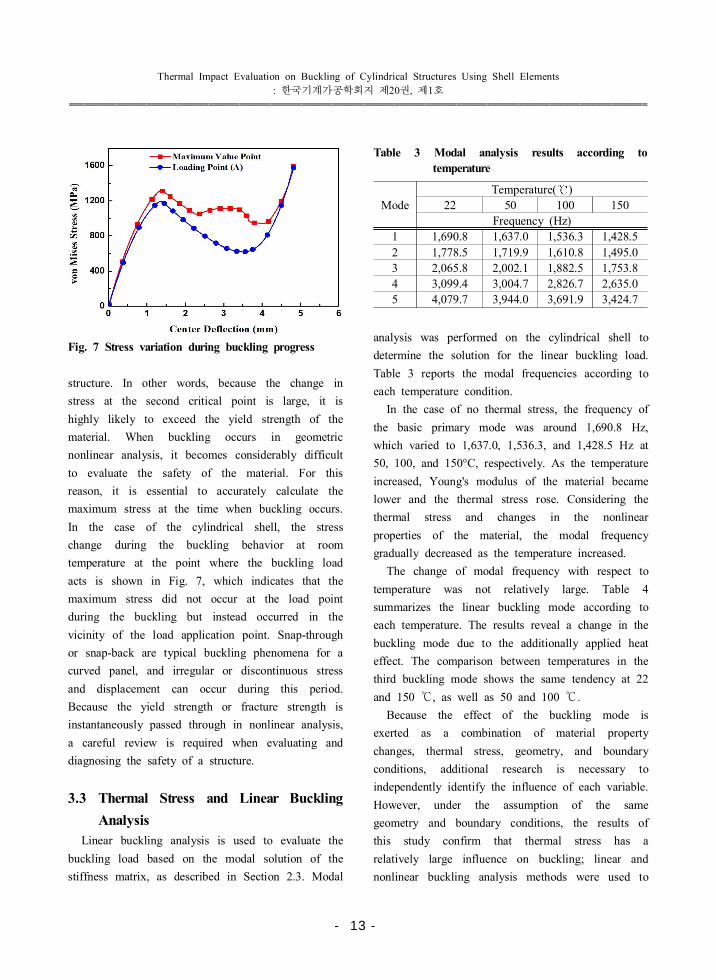
Fig. 7 Stress variation during buckling progress
structure. In other words, because the change in
stress at the second critical point is large, it is
highly likely to exceed the yield strength of the
material. When buckling occurs in geometric
nonlinear analysis, it becomes considerably difficult
to evaluate the safety of the material. For this
reason, it is essential to accurately calculate the
maximum stress at the time when buckling occurs.
In the case of the cylindrical shell, the stress
change during the buckling behavior at room
temperature at the point where the buckling load
acts is shown in Fig. 7, which indicates that the
maximum stress did not occur at the load point
during the buckling but instead occurred in the
vicinity of the load application point. Snap-through
or snap-back are typical buckling phenomena for a
curved panel, and irregular or discontinuous stress
and displacement can occur during this period.
Because the yield strength or fracture strength is
instantaneously passed through in nonlinear analysis,
a careful review is required when evaluating and
diagnosing the safety of a structure.
3.3 Thermal Stress and Linear Buckling
Analysis
Linear buckling analysis is used to evaluate the
buckling load based on the modal solution of the
stiffness matrix, as described in Section 2.3. Modal
Mode
Temperature( )
22 50 100 150
Frequency (Hz)
1 1,690.8 1,637.0 1,536.3 1,428.5
2 1,778.5 1,719.9 1,610.8 1,495.0
3 2,065.8 2,002.1 1,882.5 1,753.8
4 3,099.4 3,004.7 2,826.7 2,635.0
5 4,079.7 3,944.0 3,691.9 3,424.7
Table 3 Modal analysis results according to
temperature
analysis was performed on the cylindrical shell to
determine the solution for the linear buckling load.
Table 3 reports the modal frequencies according to
each temperature condition.
In the case of no thermal stress, the frequency of
the basic primary mode was around 1,690.8 Hz,
which varied to 1,637.0, 1,536.3, and 1,428.5 Hz at
50, 100, and 150°C, respectively. As the temperature
increased, Young's modulus of the material became
lower and the thermal stress rose. Considering the
thermal stress and changes in the nonlinear
properties of the material, the modal frequency
gradually decreased as the temperature increased.
The change of modal frequency with respect to
temperature was not relatively large. Table 4
summarizes the linear buckling mode according to
each temperature. The results reveal a change in the
buckling mode due to the additionally applied heat
effect. The comparison between temperatures in the
third buckling mode shows the same tendency at 22
and 150 , as well as 50 and 100 .℃ ℃
Because the effect of the buckling mode is
exerted as a combination of material property
changes, thermal stress, geometry, and boundary
conditions, additional research is necessary to
independently identify the influence of each variable.
However, under the assumption of the same
geometry and boundary conditions, the results of
this study confirm that thermal stress has a
relatively large influence on buckling; linear and
nonlinear buckling analysis methods were used to
- 13 -

Hee-Keun Cho 한국기계가공학회지 제 권 제 호: 20 , 1
����������������������������������������������������������������������������������������������������������������
Bucklingmode
Temperature
22 50
1
2
3
Bucklingmode 100 150
1
2
3
Table 4 Eigen buckling mode according to temperature
evaluate the influence. Table 5 summarizes changes
in the buckling load due to the thermal effect in
the linear buckling analysis. These provided the
results of calculating BLF mentioned in Section
2.3 for each variable. The linear buckling load is a
value calculated based on the mode and frequency
solution from the modal analysis.
Calculating the buckling load was achieved by
analyzing it after applying a one-unit load to point
A in the shape presented in Fig. 3. Thus, for no
thermal stress, the value of buckling load becomes
equivalent to BLF . Under thermal stress, the
effect of thermal stress increases by a multiple of
Temperature( )
22 50 100 150
Mode Buckling Load Multiplier ()
1 1,918.2 24.6 9.7 6.6
2 4,267.5 54.3 21.5 14.6
3 6,389.0 91.1 36.4 24.6
4 7,221.3 92.1 36.5 24.8
5 7,802.5 98.7 39.2 26.5
Table 5 Eigen buckling load analysis results
according to temperature
BLF because the buckling load value is obtained by
multiplying the thermal stress and the stress value
of the unit load. This can be verified by the fact
that the BLF at 50 was 24.6, which is ℃
significantly lower than 1,928.2 with no thermal
effect. Due to the cylindrical shell`s geometry, the
higher the temperature, the lower the BLF. What is
important here is that a lower BLF does not
necessarily result in a lower overall buckling load
because the value given at prestress is a
combination of thermal stress and concentrated load
rather than a single concentrated load.
The calculations of buckling load without thermal
stress are 1,106.3 N from the nonlinear static
numerical analysis (Table 2) and 1,918.2 N from
the linear buckling analysis (Table 5); this difference
can be attributed to the theoretical background of
the numerical analysis. The actual behavior was in
good agreement with the nonlinear static numerical
analysis. In particular, as the geometrical
nonlinearity became stronger in structures such as
cylindrical shells, the difference between the results
of the two analyses became higher. Because the
stiffness matrix of the material changed rapidly as
the structure deformed, the nonlinear static numerical
analysis, which involves calculations while
continuously updating the stiffness matrix, more
accurately represents the actual phenomenon. On the
other hand, because the buckling load is calculated
using the initial stiffness matrix in the case of
linear buckling analysis, the calculated and actual
- 14 -

Thermal Impact Evaluation on Buckling of Cylindrical Structures Using Shell Elements
한국기계가공학회지 제 권 제 호: 20 , 1
����������������������������������������������������������������������������������������������������������������
buckling load values were significantly different.
However, linear buckling analysis is highly accurate
for geometrical structures that are essentially linear.
4. Conclusions
In this study, the buckling phenomenon of a
cylindrical structure was analyzed by using
four-node shell elements. The results of a numerical
analysis regarding the effect of the change in
thermal stress on the buckling load due to
increasing temperature were presented. Furthermore,
it was confirmed that the thermal stress sensitively
affects the buckling behavior of the analyzed
cylindrical shell. In addition, through the analysis of
buckling and post-buckling phenomena by applying
the arc-length method and displacement control, the
exact displacement under buckling and the load in
each case were explicitly calculated according to the
change in thermal stress.
By clearly identifying the relationship between
thermal stress and buckling when designing a
structure where actual buckling occurs, the results of
this study can be used as key basic data for reliable
structural designs.
Acknowledgments
This work was supported by a Research Grant of
Andong National University.
References
1. Cho, H. K., “The Effects of Composite Laminate
Layups on Nonlinear Buckling Behavior Using a
Degenerated Shell Element,” Journal of the
Korean Society of Manufacturing Process
Engineers, Vol. 15, No. 1, pp. 50-60, 2016.
2. Thornton, E. A., “Thermal Buckling of Plates and
Shells,” Applied Mechanics Review, Vol. 46, No.
10, pp 485-506, 1993.
3. Izhak, S., “Cylindrical Buckling Load of
Laminated Columns,” Journal of Engineering
Mechanics, Vol. 115, No. 3, pp. 659-661, 1989.
4. Batterman, S. C., “Tangent Modulus Theory for
Cylindrical Shells: Buckling Under Increasing
Load,” International Journal of Solids and
Structures, Vol. 3, No. 4, pp. 501-512, 1967.
5. Hieu, P. T. and Hoang, V. T.,
“Thermomechanical Postbuckling of
Pressure-loaded CNT-Reinforced Composite
Cylindrical Shells under Tangential Edge
Constraints and Various Temperature Conditions,”
Polymer Composites, Vol. 41, No. 1, pp.
244-257, 2020.
6. Andre, M. and Nuno, D. S., “Modal analysis and
Imperfection Sensitivity of the Post-buckling
Behaviour of Cylindrical Steel Panels under
In-plane Bending,” Engineering Structures, Vol.
207, No. 15, 2020.
7. Shahsiah, R. and Esiami, M. R., “Thermal
Buckling of Functionally Graded Cylindrical
Shell,” Journal of Thermal Stress, Vol. 26, No.
3, pp. 277-294, 2011.
8. Foroutan, K., Shaterzadeh, A. and Ahmadi, H.,
“Nonlinear Static and Dynamic Hygrothermal
Buckling Analysis of Imperfect Functionally
Graded Porous Cylindrical Shells,” Applied
Mathematical Modeling, Vol. 77, pp. 539-553,
2020.
9. Zhu, J. F. and Chu, X. T., “An Improved
Arc-length Method and Application in the
Post-buckling Analysis for Composite Structures,”
Applied Mathematics and Mechanics, Vol. 23, pp.
1081-1088, 2002.
10. Hughes, T. J. R. and Liu, W. K., “Nonlinear
Finite Element Analysis of Shells: Part I.
Three-Dimensional Shells,” Computer Methods in
Applied Mechanics and Engineering, Vol. 26, No.
3, pp. 331-362, 1981.
- 15 -
Copyright © 2022 FDOKUMEN